


INSTALLATION AND USE MANUAL
DE CHIRICO
Index
page
1
INTRODUCTION....................................................................................................................................2
1. WARNINGS AND WARRANTY CONDITIONS .....................................................................................3
1.1. SAFETY WARNINGS........................................................................................................................3
1.2. GUARANTEE CONDITIONS ..............................................................................................................3
1.2.1. Exclusions................................................................................................................................3
2. DE CHIRICO CLADDING WITH FIREPLACE STOVE FORMA PURO115...............................................5
3. ASSEMBLY OF DE CHIRICO CLADDING.............................................................................................6
3.1. COMPONENTS OF DE CHIRICO CLADDING .......................................................................................6
3.2. PHASE 1 - POSITIONING OF FIREPLACE STOVE FORMA PURO115......................................................7
3.3. PHASE 2 – ASSEMBLY OF DE CHIRICO EDGE-COVER PROFILE (element 1)........................................8
3.4. PHASE 3 - ASSEMBLY OF RH SIDE AND LH SIDE (elements 2 and 3) ..................................................9
3.5. PHASE 4 - ASSEMBLY OF HOOD SUPPORT (element 4)....................................................................10
3.6. PHASE 5 – PREPARATION OF WALL FOR RECESSED INSTALLATION.................................................11
3.7. PHASE 6 - ASSEMBLY OF FRAME SUPPORT (element 5)...................................................................12
3.8. PHASE 7 – ASSEMBLY OF DE CHIRICO FRAME (element 6).............................................................14
3.9. TECHNICAL TERMS GLOSSARY OF THE PICTURES ..........................................................................15
Index Technical service – all rights reserved by mcz spa
Reproduction prohibited

INSTALLATION AND USE MANUAL
DE CHIRICO
INTRODUCTION
Dear Customer,
thank you for choosing a MCZ product and in particular the De Chirico
cladding Forma Puro 115.
We are sure that, by using it, you will appreciate the quality of an
accurately designed and tested product. Our goal is to combine
technology with easy of use and, above all, safety.
For optimal functioning of the De Chirico cladding and to fully
enjoy the heat and sense of well being that will spread
throughout your home, we suggest that you carefully read this
use and maintenance manual before using the product for the
first time; please contact your dealer should you require
assistance in resolving any doubts or problems.
Congratulations on your choice and remember, the fireplace stove
MUST NEVER be used by children who should always be kept at a
safe distance!
Introduction
page
2
Revisions to the publication
In order to improve the product, the Manufacturer reserves the right to
modify and update this publication without prior notice.
Reproduction, even partial, of this manual without the Manufacturer's
authorisation is prohibited.
Manual preservation.
• Please take care of this manual and keep it in a place that can be
quickly and easily reached.
• If this manual should be lost or destroyed, or if it is in poor
condition, request a copy from your dealer or directly from the
manufacturer, providing product identification data.
Introduction Technical service – all rights reserved by mcz spa
Reproduction prohibited

INSTALLATION AND USE MANUAL
DE CHIRICO
1. WARNINGS AND WARRANTY CONDITIONS
1.1. SAFETY WARNINGS
• Check the conditions of the surface that will support the
weight of the stove. If it is made of flammable material
(such as wood, carpet, or plastic) provide suitable
insulation.
• The user is fully liable for improper product use,
releasing MCZ from any civil or penal liabilities.
• Any tampering with the fireplace stove, or use of nonoriginal spare parts, may be hazardous to the user and
releases MCZ from any civil or penal liability.
• Incorrect installation or poor maintenance (not
compliant with the provisions of this manual) may cause
damages to persons, animals or property. MCZ is not
civilly or criminally liable in these cases.
Chapter 1
page
3
1.2. GUARANTEE CONDITIONS
MCZ guarantees the product, with the exception for the elements
subject to normal wear listed below, for two years from the date of
purchase that is proven by a document that indicates the dealer's name
and date of sale, if the completed warranty certificate was returned
within 8 days and if the product was installed and inspected by a
specialised installation technician and according to the detailed
instructions indicated in the instruction manual supplied with the
product.
The warranty includes the free replacement or repair of parts
recognised as factory defective.
1.2.1. Exclusions
The guarantee does not cover any part that may be defective
due to negligence or careless use, incorrect maintenance,
installation non compliant with that specified by MCZ.
MCZ refuses to accept any responsibility for any damage which may be
caused, directly or indirectly, by persons, animals or things as a result
of the failure to observe all the provisions set forth in the instruction
booklet, especially those concerning warnings on the subject of
installation, use and maintenance of the appliance.
In the event of product inefficiency, please contact your dealer and/or
area importer.
Damages caused by transport and handling are not covered by the
guarantee.
Exclusively refer to the supplied manual for product installation and
use.
The guarantee will be invalidated in the event of damage caused by
tampering with the appliance, atmospheric agents, natural disasters,
Chapter 1 Technical service – all rights reserved by mcz spa
Reproduction prohibited

INSTALLATION AND USE MANUAL
DE CHIRICO
electrical discharges, fire and lack of, or incorrect, maintenance in
terms of the manufacturer's instructions.
REQUEST FOR SERVICE
Requests for service must be addressed to the dealer
who shall forward the request to the MCZ technical
assistance service.
MCZ is not liable in the event the product and any
other accessory is improperly used or modified
without authorisation.
Only original MCZ spare parts must be used for all
replacements.
Chapter 1
page
4
Chapter 1 Technical service – all rights reserved by mcz spa
Reproduction prohibited
INSTALLATION AND USE MANUAL
DE CHIRICO
Chapter 2
page
5
2. DE CHIRICO CLADDING WITH FIREPLACE STOVE FORMA PURO115
The De Chirico model is a recessed cladding, i.e. the fireplace stove is recessed into the wall. Therefore it is
necessary to build a counter-wall that protrudes from the perimeter wall. The depth of the wall to be constructed
is at your discretion provided you comply with all safety distances for the fireplace stove. For this purpose please
refer to the
Manual for Installation and Use
N.B. THE WALL CONSTRUCTED DURING OPERATION WHERE THE DE CHIRICO FRAME IS FASTENED
MUST BE EQUIPPED WITH STEEL UPRIGHTS, PLACED VERTICALLY AS SHOWN IN PHASE 5.
of Forma Puro115.
1870
484164
812
VARIABILE
SICUREZZA
DISTANZA DI
MURO PERIMETRALE MURO PERIMETRALE
1870
50
Chapter 2 Technical service – all rights reserved by mcz spa
Reproduction prohibited

INSTALLATION AND USE MANUAL
DE CHIRICO
3. ASSEMBLY OF DE CHIRICO CLADDING
3.1. COMPONENTS OF DE CHIRICO CLADDING
Chapter 3
page
6
COMPONENTE
PROFILO COPRIB.DE CHIRICO
SPALLA DX
SPALLA SX
SUPPORTO CAPPA
SUPPORTO CORNICE
CORNICE DE CHIRICO
N.
1
1
1
1
1
1
VITERIA IN DOTAZIONE
VITE PER CARTONG. 3,9X35
VITE M6X25 BRUNITA
VITE AUTOPERF.PANEL.4.2X16
VITE PH-HB 3.5X9.5 BRUNITA
N.
12
6
4
2
Chapter 3 Technical service – all rights reserved by mcz spa
Reproduction prohibited

INSTALLATION AND USE MANUAL
DE CHIRICO
3.2. PHASE 1 - POSITIONING OF FIREPLACE STOVE FORMA PURO115
Chapter 3
page
7
Position Forma Puro115 as set forth in the respective
Manual for Installation and Use
(see “Safe
Distance"). Raise the unit to the desired height with respect to the floor. Concerning this, refer to the figure in
chapter 2, which indicates the extension of the De Chirico frame from under the edge-cover profile towards the
floor (164 mm). The frame does not require the machine, Forma Puro115, to be at any certain distance from the
floor. This is at your discretion, provided you comply with the minimum space for the cladding. A second
adjustment of the unit (minor variations), if necessary, is made during assembly of the cladding.
After positioning and installing the unit Forma Puro115 in accordance with the instructions in the respective
Manual for Installation and Use
, run a quick test for proper operation. If the test is successful, you can install
the De Chirico cladding.
PROFILO
COPRIBORDO
VARIABILE
NON <170 MM
DISTANZA
DI SICUREZZA
PAVIMENTO
BASE APPOGGIO
FORMA PURO
Chapter 3 Technical service – all rights reserved by mcz spa
Reproduction prohibited

INSTALLATION AND USE MANUAL
DE CHIRICO
Chapter 3
page
8
3.3. PHASE 2 – ASSEMBLY OF DE CHIRICO EDGE-COVER PROFILE (element 1)
Replace the edge-cover profile of Forma Puro 115 with the De Chirico edge-cover profile (element 1). Use the
same screws and the same holes.
PROFILO
COPRIBORDO
FORMA PURO115
PROFILO
COPRIBORDO
DE CHIRICO
Chapter 3 Technical service – all rights reserved by mcz spa
Reproduction prohibited

INSTALLATION AND USE MANUAL
DE CHIRICO
3.4. PHASE 3 - ASSEMBLY OF RH SIDE AND LH SIDE (elements 2 and 3)
Chapter 3
page
9
Fasten the right side (element 2) and the left side (element 3) to Forma Puro115 using the 4 self-tapping screws.
Panel. 4.2x16 (2 screws per side). Use the holes in the side of the unit.
Chapter 3 Technical service – all rights reserved by mcz spa
Reproduction prohibited

INSTALLATION AND USE MANUAL
DE CHIRICO
Chapter 3
page
10
3.5. PHASE 4 - ASSEMBLY OF HOOD SUPPORT (element 4)
Set the hood support on the sides (elements 2 and 3) so that the side tabs of element 4 are located in the inner
part (not visible) of elements 2 and 3. Fasten the hood support using the 2 screws PH-AB 3.5x9.5 provided.
When assembly is complete, the structure composed of De Chirico edge-cover profile - sides - hood support must
be rigid and firmly attached to the fireplace stove Forma Puro115.
ALETTA
LATERALE
A FILO
Chapter 3 Technical service – all rights reserved by mcz spa
Reproduction prohibited

INSTALLATION AND USE MANUAL
DE CHIRICO
Chapter 3
page
11
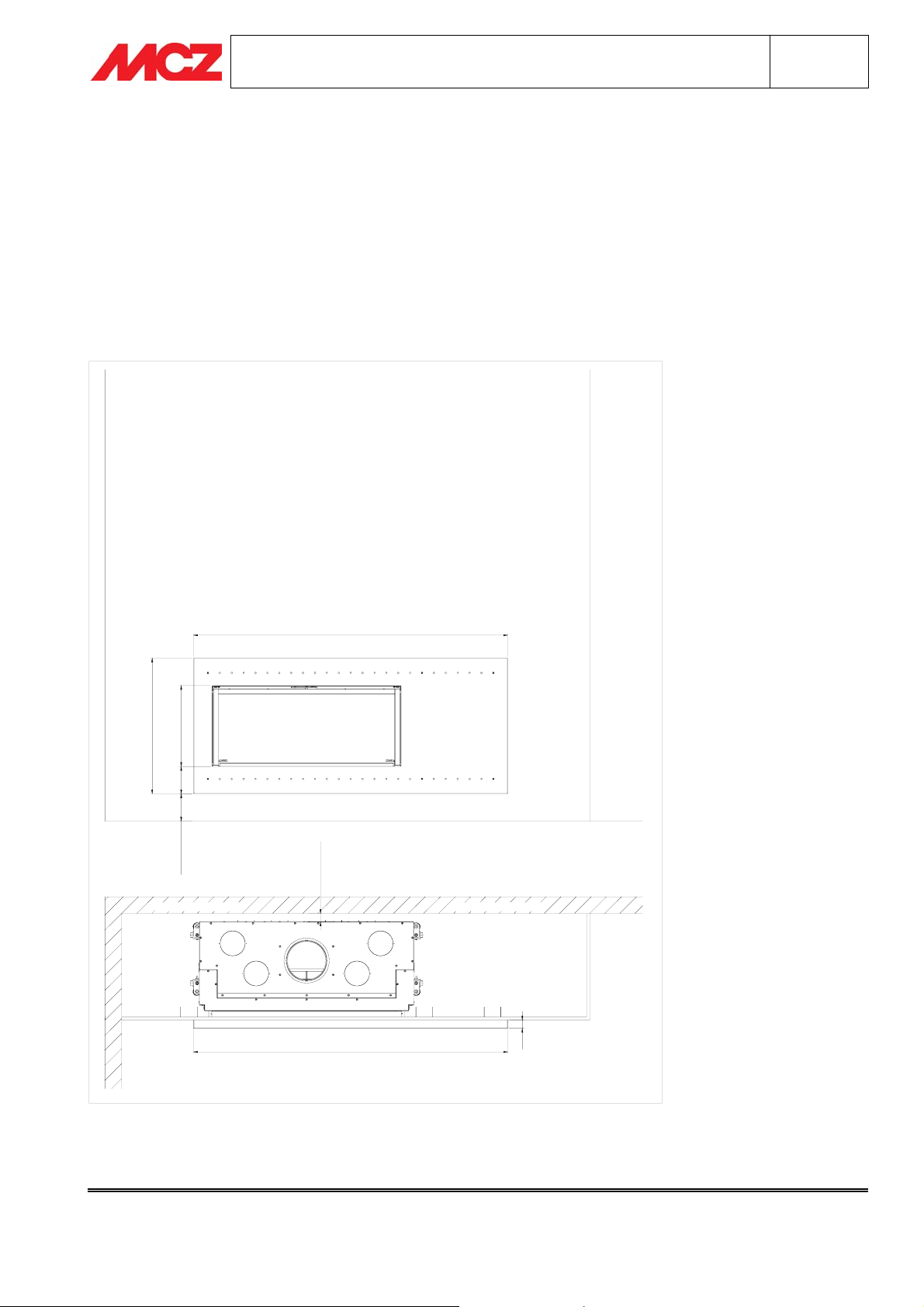
3.6. PHASE 5 – PREPARATION OF WALL FOR RECESSED INSTALLATION
The wall for recessed installation must be made during installation using fireproof material (such as fireproof
plasterboard). It must also be load-bearing and equipped with metal vertical uprights that rest on the floor.
Make an opening in the front of the wall for recessed installation measuring W=1240 mm and H=580 mm. The
distance of the hole from the floor depends on the height of the fire bed (see paragraph 3.2
of Fireplace Stove Forma Puro115
and figure below). Reinforce the wall by placing two metal uprights flush with
the hole (one for each side) and one at a distance (centre of upright) of about 530 mm to the right of the hole
(looking at the wall for recessed installation from the centre of the room).
With the wall for recessed installation prepared as instructed, the De Chirico frame is fastened to the steel
elements.
Position the wall so that the axis of opening is aligned with the axis of the fireplace stove and so that it is
indented by 4 mm with respect to the external surface of the hood support (flush with the sides: see figures).
Pase1 – Positioning
MONTANTE
FILO FORO
1240
= =
MONTANTE
FILO FORO
MONTANTE
530
580
PARETE
4
PROFILO
COPRIBORDO
SUPPORTO
CAPPA
Insulate the wall for recessed insulation from the heat of the fireplace stove. The hood support is deep enough
to provide an air space between the unit and the wall where you can insert insulation, such as insulating panels
or fibre ceramic mat.
Chapter 3 Technical service – all rights reserved by mcz spa
Reproduction prohibited

INSTALLATION AND USE MANUAL
DE CHIRICO
Chapter 3
page
12
3.7. PHASE 6 - ASSEMBLY OF FRAME SUPPORT (element 5)
Place the frame support (element 5) with the opening aligned with Forma Puro115, 10 mm from the hood
support,10 mm from each side and 20 mm from the edge-cover profile (see figure).
Fasten the frame support to the wall using the plasterboard screws provided (12) and using the holes that are
already present. If the wall has been constructed as per paragraph
steel uprights.
3.6. Phase 5
, the screws will be located at the
Chapter 3 Technical service – all rights reserved by mcz spa
Reproduction prohibited

INSTALLATION AND USE MANUAL
DE CHIRICO
Chapter 3
page
13
SPALLA
10
SUPPORTO
CORNICE
10
MONTANTE
MONTANTE
SPALLA
10
17
PROFILO
COPRIBORDO
SPAZIO PER
ISOLANTE
Chapter 3 Technical service – all rights reserved by mcz spa
Reproduction prohibited

INSTALLATION AND USE MANUAL
DE CHIRICO
Chapter 3
page
14
3.8. PHASE 7 – ASSEMBLY OF DE CHIRICO FRAME (element 6)
Position the De Chirico frame so that the six bushes in the frame support fit into the six bushes in the inner part
(not visible) of element 6. Push the Cornice De Chirico frame until it is next to the wall and fasten it using the six
screws M6X25. When assembly is complete, the De Chirico frame must be stable. Close firmly against the wall
and against the structure composed of the De Chirico edge cover profile-sides-hood support.
N.B. USE CARE IN HANDLING THE RUST-EFFECT PAINTED DE CHIRICO FRAME. DAMAGE FROM
SCRATCHES TO THIS SURFACE ARE DIFFICULT TO REPAIR.
Chapter 3 Technical service – all rights reserved by mcz spa
Reproduction prohibited

INSTALLATION AND USE MANUAL
DE CHIRICO
3.9. TECHNICAL TERMS GLOSSARY OF THE PICTURES
PAGE 5 PAGE 5
MURO PERIMETRALE PERIMETER WALL
VARIABILE VARIABLE
DISTANZA DI SICUREZZA SAFETY DISTANCE
PAGE 6 PAGE 6
COMPONENTE COMPONENT
PROFILO COPRIBORDO EDGE-COVER PROFILE
SPALLA DX RH SIDE
SPALLA SX LH SIDE
SUPPORTO CAPPA HOOD SUPPORT
SUPPORTO CORNICE FRAME SUPPORT
CORNICE DE CHIRICO DE CHIRICO FRAME
VITERIA IN DOTAZIONE NUTS AND BOLTS PROVIDED
VITE PER CARTONGESSO SCREW FOR PLASTERBOARD
VITE M6X25 BRUNITA SCREW M6X25 BURNISHED
VITE AUTOPERFORANTE PANEL 4,2X16 PANEL SELF-TAPPING SCREW 4.2X16
VITE PH-HB 3,5X9,5 BRUNITA SCREW PH-HB 3.5X9.5 BURNISHED
PAGE 7 PAGE 7
PROFILO COPRIBORDO EDGE-COVER PROFILE
VARIABILE <170 MM VARIABLE <170 MM
PAVIMENTO FLOOR
DISTANZA DI SICUREZZA SAFETY DISTANCE
BASE APPOGGIO FORMA PURO SUPPORT BASE FORMA PURO
PAGE 8 PAGE 8
PROFILO COPRIBORDO FORMA PURO115 EDGE-COVER PROFILE FORMA PURO115
PROFILO COPRIBORDO DE CHIRICO EDGE-COVER PROFILE DE CHIRICO
PAGE 10 PAGE 10
ALETTA LATERALE SIDE TAB
A FILO FLUSH
PAGE 11 PAGE 11
MONTANTE FILO FORO STEEL UPRIGHT FLUSH WITH HOLE
MONTANTE UPRIGHT
PROFILO COPRIBORDO EDGE-COVER PROFILE
PARETE WALL
SUPPORTO CAPPA HOOD SUPPORT
Glossary
page
15
Glossary Technical service – all rights reserved by mcz spa
Reproduction prohibited

INSTALLATION AND USE MANUAL
DE CHIRICO
PAGE 13 PAGE 13
SUPPORTO CORNICE FRAME SUPPORT
MONTANTE UPRIGHT
SPALLA SIDE
PROFILO COPRIBORDO EDGE-COVER PROFILE
SPAZIO PER ISOLANTE SPACE FOR INSULATION
Glossary
page
16
Glossary Technical service – all rights reserved by mcz spa
Reproduction prohibited
 Loading...