

MCZ Club AIR User Manual
8901166500
EN
INSTALLATION AND USE
MANUAL

PELLET STOVES
Chapter 1
INSTALLATION AND USE MANUAL
page 2
Introduction
Technical service - Rights reserved MCZ Group S.p.A. - Reproduction prohibited
INTRODUCTION .................................................................................................................................... 4
1. WARNINGS AND GUARANTEE CONDITIONS ..................................................................................... 5
1.1. SAFETY INSTRUCTIONS .................................................................................................................... 5
1.2. OPERATING WARNINGS .................................................................................................................... 6
1.3. IMPORTANT INFORMATION FOR CORRECT DISPOSAL OF THE PRODUCT IN ACCORDANCE WITH EC
DIRECTIVE 2002/96/EC ............................................................................................................................... 7
1.4. GUARANTEE CONDITIONS ................................................................................................................ 7
1.4.1. Limitations ................................................................................................................................. 8
1.4.2. Exclusions .................................................................................................................................. 8
2. THEORETICAL NOTIONS FOR INSTALLATION ................................................................................... 9
2.1. PELLETS ........................................................................................................................................... 9
2.2. PRECAUTIONS FOR INSTALLATION ................................................................................................. 10
2.3. OPERATING AREA ........................................................................................................................... 11
2.4. CONNECTION TO THE EXTERNAL AIR INTAKE ................................................................................. 12
2.5. CONNECTION OF SMOKE DISCHARGE PIPE ...................................................................................... 12
2.6. CONNECTION TO THE FLUE PIPE .................................................................................................... 14
2.7. CONNECTION TO AN EXTERNAL FLUE WITH INSULATED OR DOUBLE-WALL PIPE .............................. 14
2.8. CONNECTION TO THE FLUE PIPE .................................................................................................... 14
2.9. OPERATING PROBLEMS CAUSED BY DRAUGHT DEFECTS IN THE FLUE .............................................. 15
3. INSTALLATION AND ASSEMBLY ...................................................................................................... 16
3.1. DRAWINGS AND TECHNICAL CHARACTERISTICS.............................................................................. 16
3.1.1. Dimensions CLUB mod. AIR – COMFORT AIR ............................................................................. 16
3.1.2. Dimensions SUITE mod. AIR – COMFORT AIR ............................................................................ 16
3.1.3. Dimensions MUSA mod. AIR- COMFORT AIR .............................................................................. 17
3.1.4. Dimensions TOBA mod. AIR-COMFORT AIR ............................................................................... 17
3.1.5. Dimensions SAGAR mod. AIR .................................................................................................... 18
3.1.6. Dimensions NIMA mod. COMFORT AIR ...................................................................................... 19
3.1.7. Technical characteristics ........................................................................................................... 20
3.2. PREPARATION AND UNPACK ING .................................................................................................... 22
3.3. CONNECTIONS OF HOT AIR DUCTS FOR SUITE/CLUB/MUSA/NIMA AND TOBA COMFORT AIR MODEL. 25
3.4. INSTALLATION OF CERAMIC CLADDING FOR SUITE AND CLUB ......................................................... 26
3.4.1. Assembly of the lower panel – Suite and Club Stoves ................................................................. 26
3.4.2. Installation of side tiles ............................................................................................................. 27
3.4.3. Installation of ceramic top ........................................................................................................ 27
3.4.4. Assembly of sides on the MUSA stove ........................................................................................ 28
3.4.5. Assembly of ceramic side tiles onto NIMA stove ......................................................................... 29
3.4.6. Assembling the frontal/side panel and top on the Toba stove ...................................................... 30
3.4.7. Assembling side panels and top on the Sagar stove .................................................................... 33
3.5. INSTALLATION OF AIR FILTER ........................................................................................................ 35
3.6. OPENING/CLOSING OF ATHOS STOVE DOOR ................................................................................... 35
3.7. MAKING THE ELECTRICAL CONNECTIONS ....................................................................................... 35
4. OPERATION ..................................................................................................................................... 36
4.1. PRE-LIGHTING WARNINGS .............................................................................................................. 36
4.2. PRE-LIGHTING CHECK .................................................................................................................... 37
4.2.1. Note on first ignition ................................................................................................................. 37
4.3. LOADING THE PELLETS ................................................................................................................... 37
5. LCD REMOTE CONTROL ................................................................................................................... 38
5.1. Characteristics of the remote control ................................................................................................ 38
5.2. Graphic appearance ........................................................................................................................ 38
5.3. Operation of the remote control ....................................................................................................... 39
5.3.1. General rules ........................................................................................................................... 39
5.4. Initial settings ................................................................................................................................. 39
5.4.1. Adjusting the time .................................................................................................................... 39

PELLET STOVES
Chapter 1
INSTALLATION AND USE MANUAL
page 3
Introduction
Technical service - Rights reserved MCZ Group S.p.A. - Reproduction prohibited
5.4.2. °C – °F setting. ........................................................................................................................ 39
5.5. Setting the operating mode ............................................................................................................. 39
5.5.1. MANUAL mode (indicated by MAN) ............................................................................................ 39
5.5.2. AUTOMATIC mode (indicated by AUTO) .................................................................................... 39
5.5.3. TIMER mode (indicated by TIMER) ............................................................................................ 40
5.5.4. ECO mode (indicated by ECO ) ................................................................................................. 40
5.6. Various settings .............................................................................................................................. 41
5.6.1. Room ventilation ...................................................................................................................... 41
5.6.2. Sleep function .......................................................................................................................... 41
5.7. TIMER settings ............................................................................................................................... 42
5.7.1. TIMER time frame display ......................................................................................................... 42
5.7.2. Modifying the TIMER time frames ............................................................................................. 42
5.7.3. Enabling the TIMER-ECO time frames ........................................................................................ 42
6. EMERGENCY PANEL ......................................................................................................................... 43
6.1. Start-up/shutdown from emergency panel ........................................................................................ 44
6.2. SYNCHRONIZATION OF REMOTE CONTROL ..................................................................................... 44
7. SAFETY DEVICES AND ALARMS ....................................................................................................... 45
7.1. SAFETY DEVICES ............................................................................................................................ 45
7.2. ALARM SIGNALLING ........................................................................................................................ 46
7.3. Exiting alarm condition .................................................................................................................... 48
7.3.1. Mechanical shutdown of the stove ............................................................................................. 48
8. MAINTENANCE AND CLEANING ....................................................................................................... 49
8.1. DAILY AND WEEKLY CLEANING BY THE USER .................................................................................. 49
8.1.1. Before each lighting ................................................................................................................. 49
8.1.2. Check every 2/3 days ............................................................................................................... 49
8.1.3. Cleaning the glass .................................................................................................................... 50
8.1.4. Cleaning of the air filter ............................................................................................................ 50
8.2. PERIODIC CLEANING BY A SPECIALISED TECHNICIAN ..................................................................... 51
8.2.1. Cleaning of the heat exchanger ................................................................................................. 51
8.2.1.1.
8.2.1.2.
8.2.1.3.
8.2.1.4.
8.2.1.5.
8.2.1.6.
8.2.1.7.
Musa stove (steel sides) COMFORT AIR version
................................................................... 51
Suite and Club stove (ceramic sides) COMFORT AIR version
Nima Stove Version COMFORT AIR
Suite and Club stove (ceramic sides) AIR version
Sagar Stove Version AIR
Toba Stove AIR Version
.................................................................................................... 57
..................................................................................................... 58
Toba Stove COMFORT AIR Version
..................................................................................... 55
................................................................. 56
..................................................................................... 59
................................................. 53
8.2.2. CLEANING THE LOWER COMPARTMENT .................................................................................... 60
8.2.3. Shutting the stove down (end of season) ................................................................................... 60
8.2.4. Check of internal components ................................................................................................... 60
9. PROBLEMS / CAUSES / SOLUTIONS ................................................................................................ 62
10. ELECTRICAL DIAGRAMS ................................................................................................................ 64
PELLET STOVES
Chapter 1
INSTALLATION AND USE MANUAL
page 4
Introduction
Technical service - Rights reserved MCZ Group S.p.A. - Reproduction prohibited
ATTENTION
This warning sign indicates that the message to which it
refers should be carefully read and understood, because
failure to comply with what these notices say can cause
serious damage to the stove and put the user's safety at
risk.
INFORMATION
This symbol is used to highlight information which is
important for proper stove operation. Failure to comply with
these provisions will compromise use of the stove and its
operation will not be satisfactory.
OPERATING SEQUENCES:
Indicates a sequence of buttons to be pushed to access
menus or to make adjustments.
MANUAL
Indicates that you should carefully read this manual or the
related instructions.
INTRODUCTION
Dear Customer,
We wish to thank you for choosing an MCZ product, specifically a stove
of the MCZ pellet line.
In order to get the best performance from your stove and to
enjoy to the full the warmth and the sense of well-being which
the flame will diffuse through the home, we recommend that
you read this booklet carefully before lighting the stove for the
first time.
While thanking you again, may we remind you that the stove MUST
NOT be used by children, and that they must always be kept at a safe
distance from it!
Revisions to the publication
In order to improve the product, to keep this publication up to date the
manufacturer reserves the right to make modifications without any
advance notice. Any reproduction, even in part, of this manual without
the consent of the manufacturer is prohibited.
Care of the manual and how to consult it
Take good care of this manual and keep it in a place which can
easily and quickly be reached.
If this manual should be lost or destroyed, or if it is in poor
condition, ask for a copy from your retailer or directly from the
manufacturer, providing product identification data.
Information which is essential or that requires special attention is
shown in bold text.
Italic text
is used to call your attention to other paragraphs in the
manual or for any additional clarifications.
SYMBOLS USED IN THE MANUAL
PELLET STOVES
Chapter 1
INSTALLATION AND USE MANUAL
page 5
Warnings and guarantee conciliations
Technical service - Rights reserved MCZ Group S.p.A. - Reproduction prohibited
Installation of the stove, making the electrical
connections, checking its operation, and
maintenance are all tasks which should be carried
out by qualified and authorised personnel.
Install the stove in accordance with the
regulations in force in your local area, region and
country.
This apparatus cannot be used by people
(including children with limited physical, sensorial
or mental abilities or with little experience and
know-how unless they have been viewed or
instructed on the use of the apparatus by the
person responsible for its safety.
For the correct use of the stove and of the electronic
apparatus connected to it, and to prevent accidents, the
instructions given in this booklet must always be
followed.
Use, adjustment and programming must be carried out
by adults. Errors or incorrect settings may cause
hazardous conditions and/or poor operation.
Before beginning any operation, the user, or whoever is
preparing to operate on the stove, must have read and
understood the entire contents of this instruction
booklet.
The stove is to be used only for its intended purpose.
Any other use is to be considered improper and
therefore hazardous.
Do not use the stove for standing on or as any kind of
support.
Do not put clothes to dry on the stove Any clothes
hangers and suchlike must be kept a suitable distance
from the stove. Danger of fire.
All responsibility for improper use is taken entirely by the
user and such use relieves MCZ of any civil or criminal
responsibility.
Any kind of tampering or unauthorised substitution of
non-original spare parts can be hazardous for the safety
of the operator and relieves MCZ of any civil or criminal
responsibility.
Most of the surfaces of the stove are extremely hot (the
door, the handle, the glass, smoke discharge pipes etc.).
Avoid coming into contact with these parts, therefore,
without adequate protective clothing or suitable
implements, such as gloves with thermal protection or
implements which keep the hands cool.
Under no circumstances should the stove be run
with the door open or the glass broken.
Do not touch the stove with wet hands, in view of the
fact that it is an electrical appliance. Always disconnect
the supply cable before doing anything to the unit.
1. WARNINGS AND GUARANTEE CONDITIONS
1.1. SAFETY INSTRUCTIONS
PELLET STOVES
Chapter 1
INSTALLATION AND USE MANUAL
page 6
Warnings and guarantee conciliations
Technical service - Rights reserved MCZ Group S.p.A. - Reproduction prohibited
Before carrying out any cleaning or maintenance
operation, make sure in advance that the stove is
disconnected from the mains electricity supply, by
turning off the main switch located on the back of the
stove, or by unplugging the supply cable.
If there is a fire in the flue pipe, extinguish the stove,
disconnect it from the power supply and never open the
door. Then contact the competent authorities.
The stove must be electrically connected to a system
equipped with an effective earth conductor.
The system must be of adequate rated capacity for the
stated electrical power of the stove.
Incorrect installation or faulty maintenance (not
conforming to the requirements set out in this booklet)
can cause harm to people, animals or property. In such
cases MCZ is absolved from any civil or criminal
responsibility.
Shut the stove down in the event of a breakdown or
bad running.
Pellets must not be fed manually into the burner.
Accumulated unburnt pellets in the burner after
repeated failed ignitions must be removed before
lighting.
Do not wash the inside of the stove with water.
Do not wash the stove with water. The water could get
inside the unit and damage the electrical insulation and
cause electric shocks.
Do not expose your own body to hot air for extended
periods. Do not overheat the room you are in and
where the stove is installed. This could cause injuries
and health problems.
Do not expose plants or animals directly to a current of
hot air. There could be harmful effects on them
Do not put any fuels in the hopper but wood pellets.
Install the stove in a location with adequate means of
fire-prevention and equipped with all services such as
power supply (air and electricity) and fume discharge.
If the stove and the ceramic cladding are in storage, it
should be in a place that is free of damp, and they
should not be exposed to extremes of temperature.
It is inadvisable to base the stove directly on the floor,
and if the floor is made of flammable material, it must
be suitably insulated.
Do not light the stove with flammable materials if the
ignition system breaks down.
1.2. OPERATING WARNINGS
PELLET STOVES
Chapter 1
INSTALLATION AND USE MANUAL
page 7
Warnings and guarantee conciliations
Technical service - Rights reserved MCZ Group S.p.A. - Reproduction prohibited
INFORMATION
In case of any problems, get in touch with your dealer, or a
qualified engineer authorised by MCZ, and if a repair is
necessary, insist on the use of original spare parts.
Use only the fuel recommended by MCZ (for Italy pellets
with a diameter of 6 mm and for other European
countries with a diameter of 6-8 mm) and provided only
with an automatic supply system.
Periodically check and clean the smoke outlet ducts
(connection to the flue pipe).
Accumulated unburnt pellets in the burner after
repeated failed ignitions must be removed before
lighting.
The pellet stove is not a cooking appliance.
Always keep the cover of the fuel hopper closed.
Keep this instruction manual carefully because it must
stay with the stove throughout its working life. If the
stove is sold or transferred to another user, always make
sure that the booklet goes with the product.
If it gets lost, ask MCZ or your authorised dealer for
another copy.
MCZ guarantees the stove, excluding the components
which are subject to normal, for a period of two years
from the date of purchase, as proved by a supporting
document which gives the name of the vendor and the date
on which the sale took place. The guarantee is conditional
on the guarantee certificate being filled in and returned
within 8 days, and requires that the product be installed and
tested by a specialised installer, according to the detailed
instructions given in the instruction booklet supplied with the
product.
1.3. IMPORTANT INFORMATION FOR CORRECT
DISPOSAL OF THE PRODUCT IN ACCORDANCE WITH
EC DIRECTIVE 2002/96/EC
.
At the end of its working life, the product must not be disposed of as
urban waste.
It must be taken to a special local authority differentiated waste
collection centre or to a dealer providing this service.
Disposing of a appliance separately avoids possible negative
consequences for the environment and health deriving from
inappropriate disposal and enables the constituent materials to be
recovered to obtain significant savings in energy and resources.
As a reminder of the need to dispose of appliances separately, the
product is marked with a crossed-out wheeled dustbin.
1.4. GUARANTEE CONDITIONS
PELLET STOVES
Chapter 1
INSTALLATION AND USE MANUAL
page 8
Warnings and guarantee conciliations
Technical service - Rights reserved MCZ Group S.p.A. - Reproduction prohibited
The term 'guarantee' is to be understood to denote the freeof-charge replacement or repair of parts recognised to
have been defective at the start by reason of
manufacturing defects.
CLAIMS UNDER THE GUARANTEE
the request for action under the guarantee must be
addressed to the retailer, who will forward the claim
to MCZ's technical assistance service.
MCZ refuses to accept any responsibility in the event
that the stove or any other accessory have been
improperly used or modified without authorisation.
For all replacement of parts, only original MCZ spare
parts must be used.
1.4.1. Limitations
The above guarantee does not cover components relating to electrical
and electronic parts, or fans, on which the guarantee period is 1 year
from the purchase of the product, documented as specified above. The
guarantee does not cover parts subject to normal wear such as gaskets,
glass, and any parts with can be removed from the firebox.
The replacement parts will be guaranteed for the remainder of the
guarantee period starting from the date of purchase of the product.
1.4.2. Exclusions
Variations in colour in the painted or ceramic parts, and crackling of the
glaze on the ceramics, do not constitute grounds for a claim under the
guarantee, as they are natural characteristics of the material and of the
use of the product.
The guarantee does not cover any parts which may be found to be
faulty as a result of negligence or carelessness in use, or of incorrect
maintenance, or of installation not complying with MCZ's specification
(see the relevant chapters in this user manual).
MCZ refuses to accept any responsibility for any damage which may be
caused, directly or indirectly, by persons, animals or things in
consequence of the failure to observe all the prescriptions laid down in
the instruction booklet, especially those concerning warnings on the
subject of installation, use and maintenance of the appliance.
If the product does not perform correctly, contact your local retailer
and/or importer.
Damage caused by transport and/or handling is excluded from the
guarantee.
For installation and use of the product, reference must be made
exclusively to the booklet supplied.
The guarantee will be invalidated in the event of damage caused by
tampering with the appliance, atmospheric agents, natural disasters,
electrical discharges, fire, defects in the electrical system, and caused
by lack of, or incorrect, maintenance in terms of the manufacturer's
instructions.
PELLET STOVES
Chapter 2
INSTALLATION AND USE MANUAL
page 9
Theoretical notions for installation
Technical service - Rights reserved MCZ Group S.p.A. - Reproduction prohibited
The poorer the quality of the fuel, the more
frequently will intervention be necessary for cleaning
the internal parts, such as the grate and the
combustion chamber.
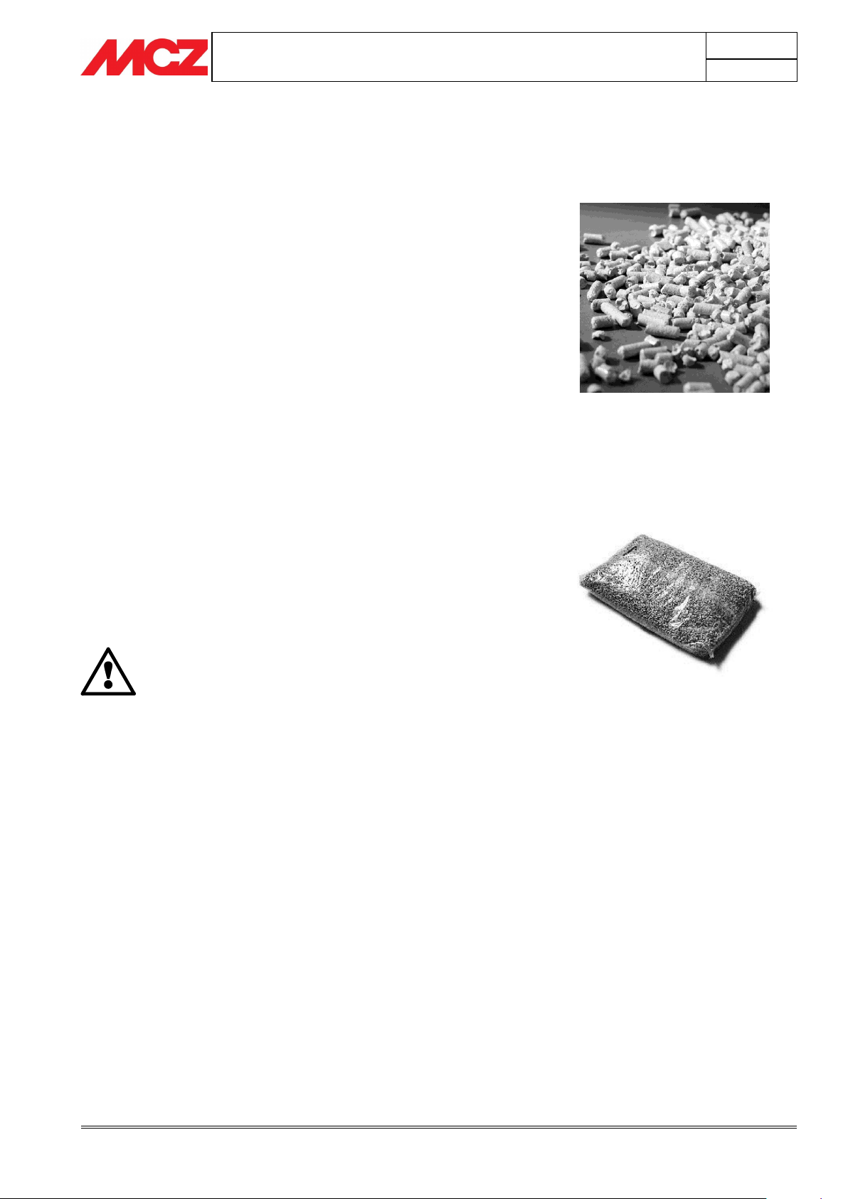
Fuel pellets
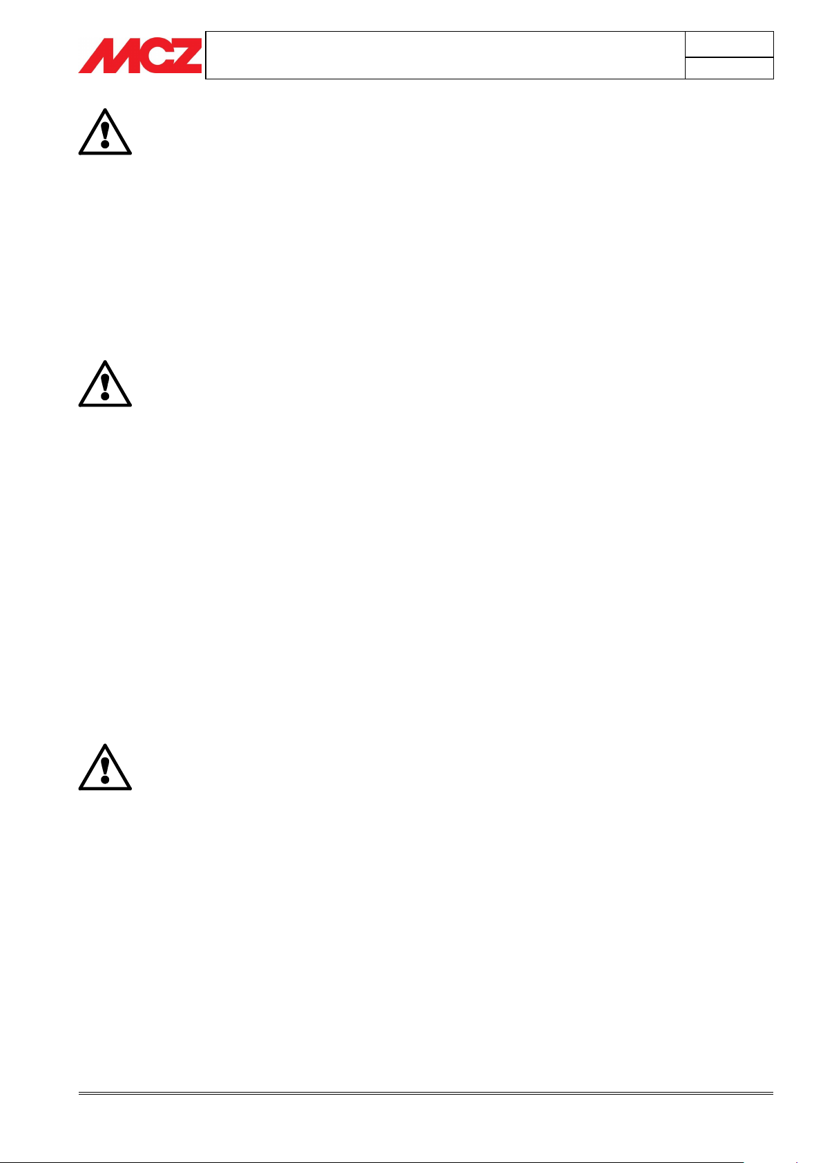
15 Kg sack of fuel
2. THEORETICAL NOTIONS FOR INSTALLATION
2.1. PELLETS
Wood pellets are manufactured by hot-extruding compressed sawdust which
is produced during the working of natural dried wood. The compactness of the
material comes from the lignin which is contained in the wood itself, and
allows the production of pellets without the use of glues or binders.
The market offers different types of pellet with characteristics which
vary depending on what mixture of woods is used. The diameter varies
between 6 mm and 8 mm, with a standard length in the range 5 mm to
30 mm. Good quality pellets have a density which varies between 600
kg/m3 and 750 kg/m3, with a moisture content which varies from 5%
to 8% by weight.
Besides being an ecological fuel (exploiting timber residues to the
maximum and achieving cleaner combustion than is possible with fossil
fuels), pellets also have technical advantages. While good-quality timber
has a calorific power of 4.4 kW/kg (with 15% moisture, therefore after
about 18 months' seasoning), the equivalent figure for pellets is 4.9
kW/kg.
To ensure good combustion, the pellets must be stored in an area that
is free of humidity and protected from dirt. The pellets are usually
supplied in 15 kg. sacks, so storing them is very convenient.
Good quality pellets ensure good combustion, thus lowering the
emission of harmful agents into the atmosphere.
The main certifications of quality for pellets in the European market are
DINplus and Ö-Norm M7135; these ensure respect of:
Calorific power: 4,9 kW/kg
Water content: max 10% of weight
Percentage of ashes: max 0,5% of weight
Diameter: 5 – 6mm
Length: max 30mm
Contents: 100% untreated wood, with no added bonding
substances (bark percentage 5% max)
Packaging: in sacks made from ecologically compatible or
biologically decomposing material
PELLET STOVES
Chapter 2
INSTALLATION AND USE MANUAL
page 10
Theoretical notions for installation
Technical service - Rights reserved MCZ Group S.p.A. - Reproduction prohibited
MCZ strongly recommends using certified fuel in its
stoves (DINplus e Ö-Norm M7135).
The use of fuel of inferior quality or not conforming
to the specification given above compromises the
running of your stove and can therefore lead to the
termination of the guarantee and of the
manufacturer's responsibility for the product.
MCZ pellet stoves run exclusively on pellets with a
diameter of 6 mm (only for Italy) and 6-8 mm
(European countries) with lengths that go from 5
mm to 30 mm.
IMPORTANT!
Installation and assembly of the stove must be
carried out by qualified personnel.
IMPORTANT!
The stove must be connected to a flue pipe or a
vertical duct which can discharge the fumes at the
highest point of the building.
The fumes are however derived from the combustion
of wood products, and if they come into contact with
or close to walls, they can make dirty marks.
Also take care because the fumes are very hot but
almost invisible, and can cause burns on contact.
The holes for the passage of the smoke pipe and for
the intake of air from outside should be made before
positioning the stove unit.
2.2. PRECAUTIONS FOR INSTALLATION
The stove must be installed in a suitable position to allow the normal
operations of opening and ordinary maintenance.
The site must be:
capable of providing the environmental conditions for operation
equipped with power supply 230V 50 Hz
capable of taking an adequate system for smoke discharge
provided with external ventilation
provided with an earth connection complying with CEI 64-8
The stove must be connected to a flue pipe or an internal or
external vertical duct conforming to current standards UNI
7129 - 7131 9615.
The stove must be positioned in such a way that the electrical
plug is accessible.
PELLET STOVES
Chapter 2
INSTALLATION AND USE MANUAL
page 11
Theoretical notions for installation
Technical service - Rights reserved MCZ Group S.p.A. - Reproduction prohibited
It is not permissible to install the stove in bedrooms,
bathrooms or showers, or in a room where another
heating appliance is installed (fireplace, stove etc.)
which does not have its own independent air intake.
Locating the stove in a room with an explosive
atmosphere is prohibited.
The floor of the room where the stove is to be
installed must be strong enough to take its weight.
If the floor is wooden, we recommend the use of a
floor guard in compliance with the applicable
standards in force in the country of installation.
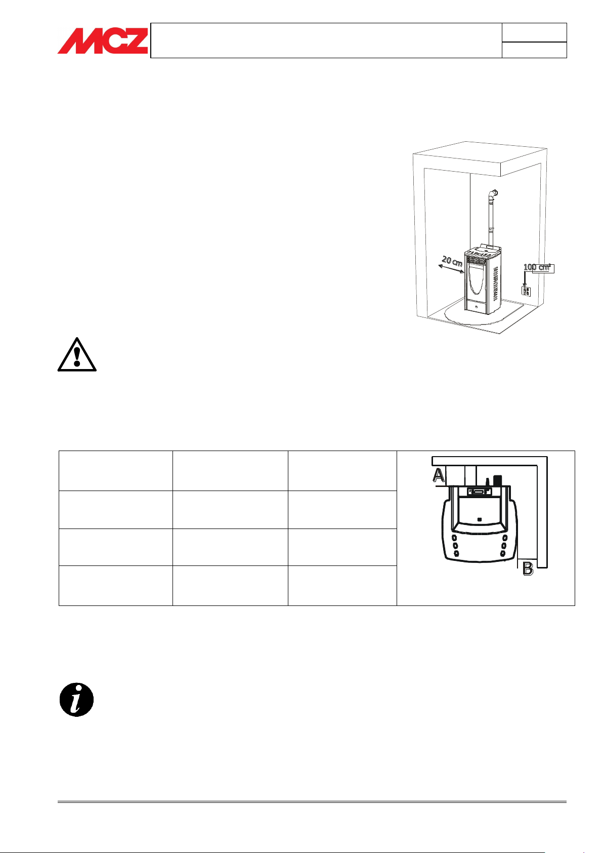
Example of pellet stove installation
SUITE/CLUB/MUSA/
NIMA/TOBA
Non-flammable
walls
Flammable walls
Air version
A=5cm
B=5cm
A=5cm
B=10cm
Comfort Air version
with diffuser
A=15cm
B=15cm
A=20cm
B=20cm
Ducted Comfort Air
version
A=5cm
B=15cm
A=5cm
B=20cm
2.3. OPERATING AREA
For proper functioning and a good temperature distribution, the stove
should be positioned in a location where it is able to take in the air
necessary for combustion of the pellets (about 40 m3/h must be
available), as laid down in the standard governing the installation and
in accordance with local national standards.
The volume of the room must not be less than 30 m3.
The air must come in through permanent openings made in walls (in
proximity to the stove) which give onto the outside, with a minimum
cross-section area of 100 cm2.
These openings must be made in such a way that it is not possible for
them to be obstructed in any way.
Alternatively, the air can be taken from rooms adjacent to the one
which needs ventilating, as long as they are provided with an air intake
from the outside, and are not used as bedrooms or bathrooms, and
provided there is no fire risk such as there is for example in garages,
woodsheds, and storerooms, with particular reference to what is laid
down in current standards.
If the room contains objects which are believed to be particularly
delicate, such as drapes, sofas and other furniture, their distance from
the stove should be considerably increased.
PELLET STOVES
Chapter 2
INSTALLATION AND USE MANUAL
page 12
Theoretical notions for installation
Technical service - Rights reserved MCZ Group S.p.A. - Reproduction prohibited
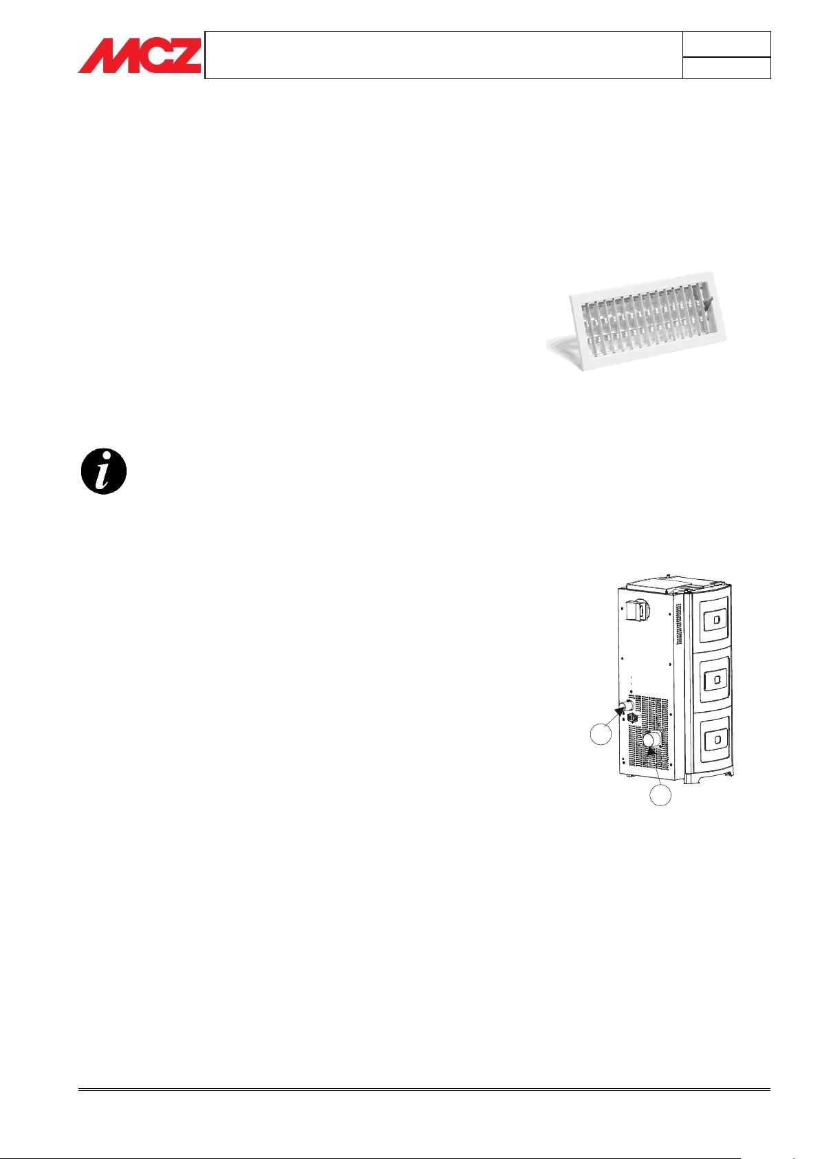
1
2
It is not compulsory to connect the air intake directly
with the stove (so that it draws air directly from
outside), but it is essential at all events to ensure an
airflow of 50 cubic metres per hour by the use of a
hole of the dimensions given.
See standard UNI 10683.
Rear view of a pellet stove
1) Smoke outlet
2) Combustion air intake
2.4. CONNECTION TO THE EXTERNAL AIR INTAKE
It is essential that at least as much air must be able to flow into the
room where the stove is installed as is required for proper combustion
in the appliance and for the ventilation of the room. This can be
effected by means of permanent openings in the walls of the room to
be ventilated, which give onto the outside, or by single or collective
ventilation ducts.
For this purpose, on the external wall near the stove, a hole must be
made with a minimum free cross-section of 100 cm². (equivalent to a
round hole of 12 cm diameter or a square hole 10x10 cm), protected by
a grille on the inside and the outside.
The air intake must also:
communicate directly with the room where the stove is installed
be protected by a grille, metal mesh or suitable guard, as long as
this does not reduce the area below the minimum.
be positioned in such a way as to be impossible to obstruct
2.5. CONNECTION OF SMOKE DISCHARGE PIPE
When making the hole for the passage of the smoke discharge pipe, it
is necessary to take into account the possible presence of flammable
materials. If the hole has to pass through a wall made of wood or
thermolabile material, THE FITTER MUST under all circumstances
observe the minimum safe distance from all combustible materials
(value stated on the pipe certification label) and provide any additional
insulation using appropriate materials (thickness 1.35cm with minimum
thermal conductivity of 0.07 W/m°K).
The same is true if the stove pipe must run through vertical or
horizontal stretches passing in proximity (min.20cm) to the heatsensitive wall
As an alternative we recommend the use of insulated pipe, which can
also be used on the outside to avoid condensation.
The combustion chamber works in low pressure. The smoke duct for
the discharge of fumes will also be under low pressure when connected
to an efficient flue pipe as directed.
PELLET STOVES
Chapter 2
INSTALLATION AND USE MANUAL
page 13
Theoretical notions for installation
Technical service - Rights reserved MCZ Group S.p.A. - Reproduction prohibited
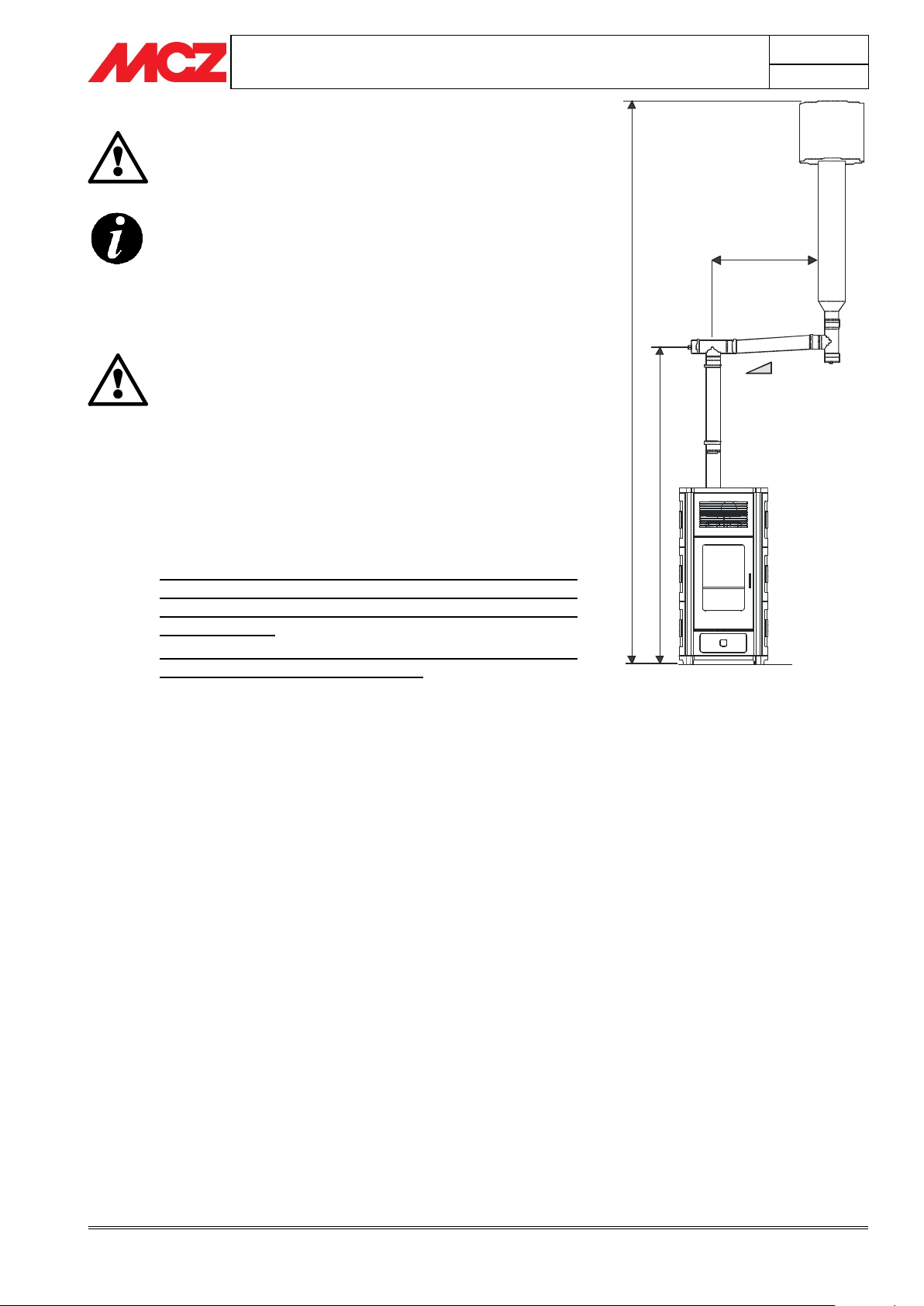
3-5 %
2 - 3 mt. MAX
H
>
4
m
t
.
H
>
1
,
5
m
t
.
Pipes and unions with suitable gaskets must always
be used, to guarantee a hermetic seal.
All sections of the smoke duct must be inspectable and
removable to enable periodic internal cleaning. Tee
connectors with inspection caps should be used.
IMPORTANT!
All 90 degree changes of direction in the flue pipe
must be fitted with suitable tee connectors to allow
the possibility of inspection. (see accessories for
pellet stove)
It is absolutely prohibited to fit a grille on the end of
the discharge pipe, because it could lead to poor
running of the stove.
FOR CONNECTION TO THE FLUE PIPE, NOT MORE
THAN 2-3 METRES OF HORIZONTAL PIPE MUST BE
USED AND NOT MORE THAN THREE 90° CURVES
MUST BE USED
IT IS ALSO ADVISABLE NOT TO EXCEED 6 METRES IN
LENGTH WITH THE PIPE Ø 80 mm
Example of pellet stove installation
Position the stove bearing in mind all the instructions and considerations
above.
PELLET STOVES
Chapter 2
INSTALLATION AND USE MANUAL
page 14
Theoretical notions for installation
Technical service - Rights reserved MCZ Group S.p.A. - Reproduction prohibited
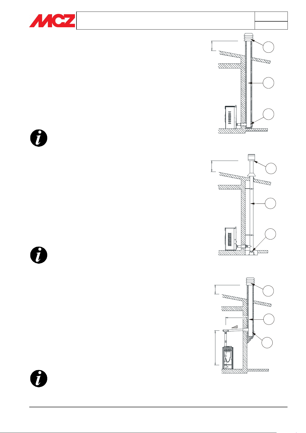
This type of connection ensures the evacuation of the
fumes even in the event of a temporary power cut.
This type of connection ensures the evacuation of the
fumes even in the event of a temporary power cut.
This type of connection ensures the evacuation of the
fumes even in the event of a temporary power cut.
0,5 mt.
1
2
3
1) Windproof cowl
2) Flue pipe
3) Inspection
0,5 mt.
2
1
3
1) Windproof cowl
2) Flue pipe
3) Inspection
3-5 %
2 - 3 mt. MAX
0,5 mt.
H
>
1
,
5
m
t
.
3
2
1
1) Windproof cowl
2) Flue pipe
3) Inspection
2.6. CONNECTION TO THE FLUE PIPE
The flue pipe must have internal dimensions not larger than 20 x 20 cm,
or diameter 20 cm. In the event of larger dimensions, or of the flue
pipe being in poor condition (for example cracks, poor insulation, etc.),
it is advisable to fit a stainless steel pipe of suitable diameter inside the
flue pipe throughout its length, right up to the top.
Check with suitable instruments that there is a minimum draught of 10 Pa.
At the bottom of the flue pipe, provide an inspection cap to allow
periodic checking and cleaning, which must be done annually.
Make a gas-tight connection to the flue pipe, using pipes and
connectors as recommended by us.
You must ensure that a windproof cowl should be fitted which complies
with the standards in force.
2.7. CONNECTION TO AN EXTERNAL FLUE WITH
INSULATED OR DOUBLE-WALL PIPE
The external fluepipe must have internal dimensions of minimum 10x10
cm or 10 cm diameter, and maximum 20x20 cm or 20 cm diameter.
Check with suitable instruments that there is a minimum draught of 10 Pa.
The only type of pipe which is permissible is insulated (double-walled)
stainless steel, smooth on the inside, fixed to the wall. Flexible stainless
steel pipe must not be used. At the bottom of the flue pipe, provide an
inspection cap to allow periodic checking and cleaning, which must be
done annually. Make a gas-tight connection to the flue pipe, using
pipes and connectors as recommended by us.
You must ensure that a windproof cowl should be fitted which complies
with the standards in force.
2.8. CONNECTION TO THE FLUE PIPE
For proper functioning, the connecting pipe between the stove and the
chimney or flue duct must have a slope of not less than 3% in the
horizontal stretches, the length of which must not exceed 2/3
metres, and the vertical distance between one tee connector and
another (change of direction) must not be less than 1.5m.
Check with suitable instruments that there is a minimum draught of 10 Pa.
At the bottom of the flue pipe, provide an inspection cap to allow
periodic checking and cleaning, which must be done annually.
Make a gas-tight connection to the flue pipe, using pipes and
connectors as recommended by us.
You must ensure that a windproof cowl should be fitted which complies
with the standards in force.
PELLET STOVES
Chapter 2
INSTALLATION AND USE MANUAL
page 15
Theoretical notions for installation
Technical service - Rights reserved MCZ Group S.p.A. - Reproduction prohibited
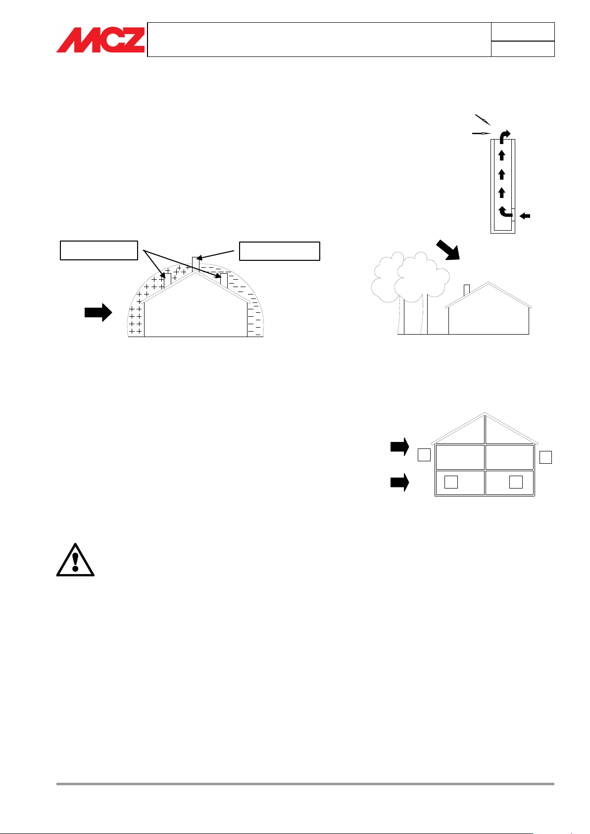
IMPORTANT!
The operation of the pellet stove is noticeably
sensitive to the conformation and position of the flue
which is adopted.
Hazardous conditions can only be overcome by
suitable setting-up of the stove carried out by
qualified MCZ personnel.
1
2 3
4
E.g. Crosswind 2: 8 m/sec
Depression of 30Pa
E.g. Downdraft at 45° of
8m/sec. Overpressure of 17
Pa
1-2 = High-pressure zones
3-4 = Low-pressure zones
WIND
Least favourable points
Most favourable position
WIND
Downdraft
High-pressure zone
Low-pressure zone
2.9. OPERATING PROBLEMS CAUSED BY DRAUGHT
DEFECTS IN THE FLUE
Of all the weather and geographical conditions which affect the
operation of a flue pipe (rain, fog, snow, altitude a.s.l., exposure to
sunlight, direction of facing), the wind is unquestionably the most
decisive. In fact, along with thermal depression caused by the
difference in temperature inside and outside of the chimney, there is
another type of depression or over-pressure: dynamic pressure caused
by the wind. An updraft always increases depression and hence
draught. A crosswind increases depression provided the cowl has been
installed properly. A downdraft always decreases depression, at times
inverting it.
Besides the direction and force of the wind, the position of the flue and
the cowl with respect to the roof of the building and the surrounding
landscape is important.
The wind also influences the operation of the chimney indirectly by
creating high-pressure and low-pressure zones, not only outside the
building but inside as well. In rooms directly exposed to the wind (2),
an indoor high-pressure area can be created which can augment the
draught in stoves and fireplaces, but it can be counteracted by the
external high pressure if the cowl is situated on the side exposed to the
wind (1). On the other hand, in the rooms on the opposite side from
the direction of the wind (3), a dynamic depression can be created
which competes with the natural thermal depression developed by the
chimney, but this can be compensated for (sometimes) by locating the
flue on the opposite side from the direction of the wind (4).

PELLET STOVES
Chapter 3
INSTALLATION AND USE MANUAL
page 16
Installation and assembly
Technical service - Rights reserved MCZ Group S.p.A. - Reproduction prohibited
1
0
0
9
2
5
9
226
187
4
3
9
60
6
0
413
1
1
4
9
6
0
3
0
578
5
5
8
7
3
6
3
Ø48
Ø80
323
1
4
0
COLD AIR INLET
COMFORT AIR
HOT AIR OUTLET
1
1
4
9
323
1
0
0
9
2
5
9
413
226
187
4
3
9
60
6
0
6
0
30
5
5
8
578
7
1
6
3
Ø48
Ø80
1
4
0
COMFORT AIR
HOT AIR OUTLET
3. INSTALLATION AND ASSEMBLY
3.1. DRAWINGS AND TECHNICAL CHARACTERISTICS
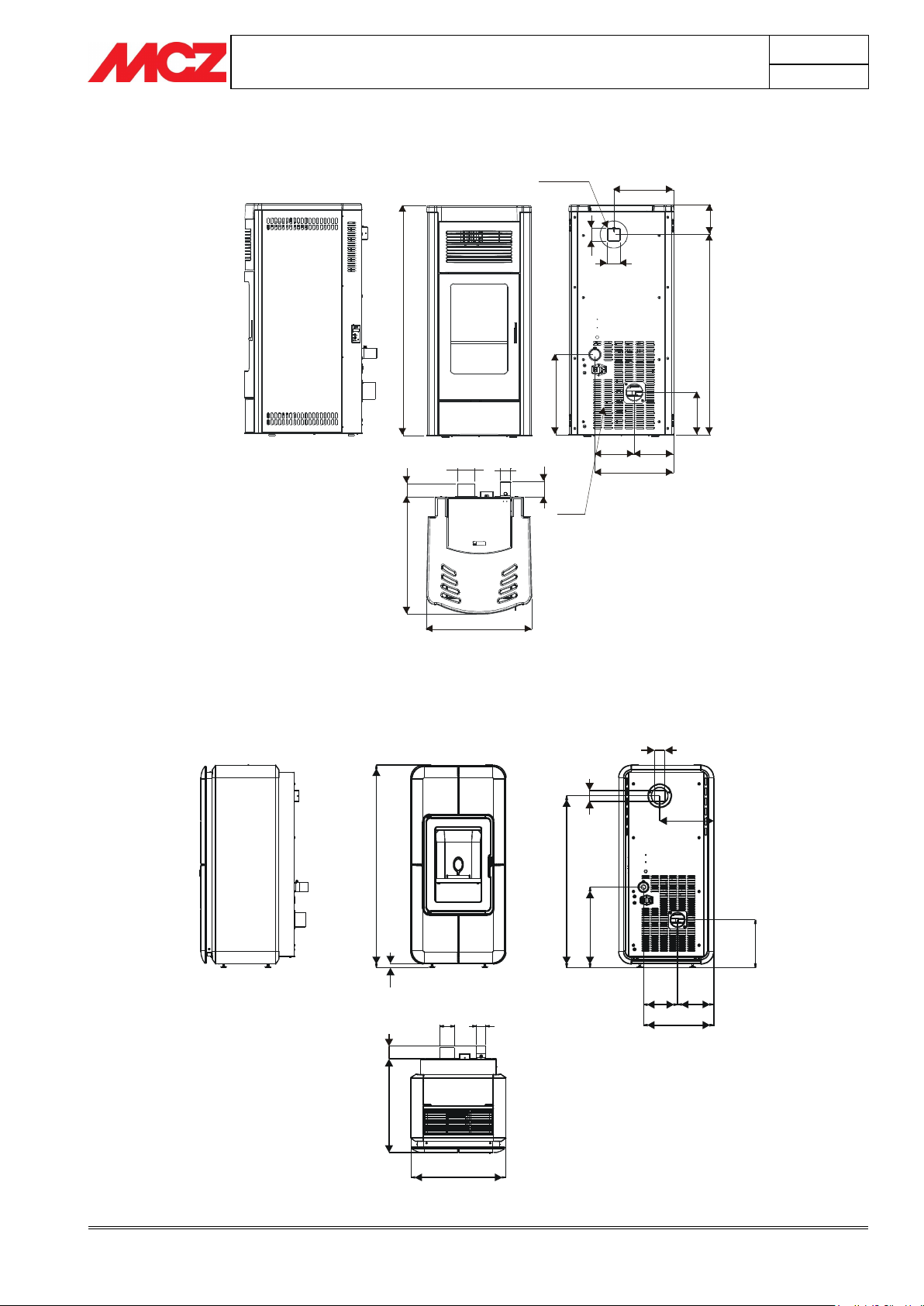
3.1.1. Dimensions CLUB mod. AIR – COMFORT AIR
3.1.2. Dimensions SUITE mod. AIR – COMFORT AIR
PELLET STOVES
Chapter 3
INSTALLATION AND USE MANUAL
page 17
Installation and assembly
Technical service - Rights reserved MCZ Group S.p.A. - Reproduction prohibited
1
0
9
3
9
5
2
2
0
2
284
60
6
0
373
186
187
3
8
2
502
5
5
9
6
3
Ø80
Ø48
7
3
1
4
1
COLD AIR INLET
COMFORT AIR
HOT AIR OUTLET
1
1
1
0
2
0
2
6
2
387
200
187
4
4
2
9
4
2
60
298
6
0
523
5
1
4
7
0
Ø80
Ø48
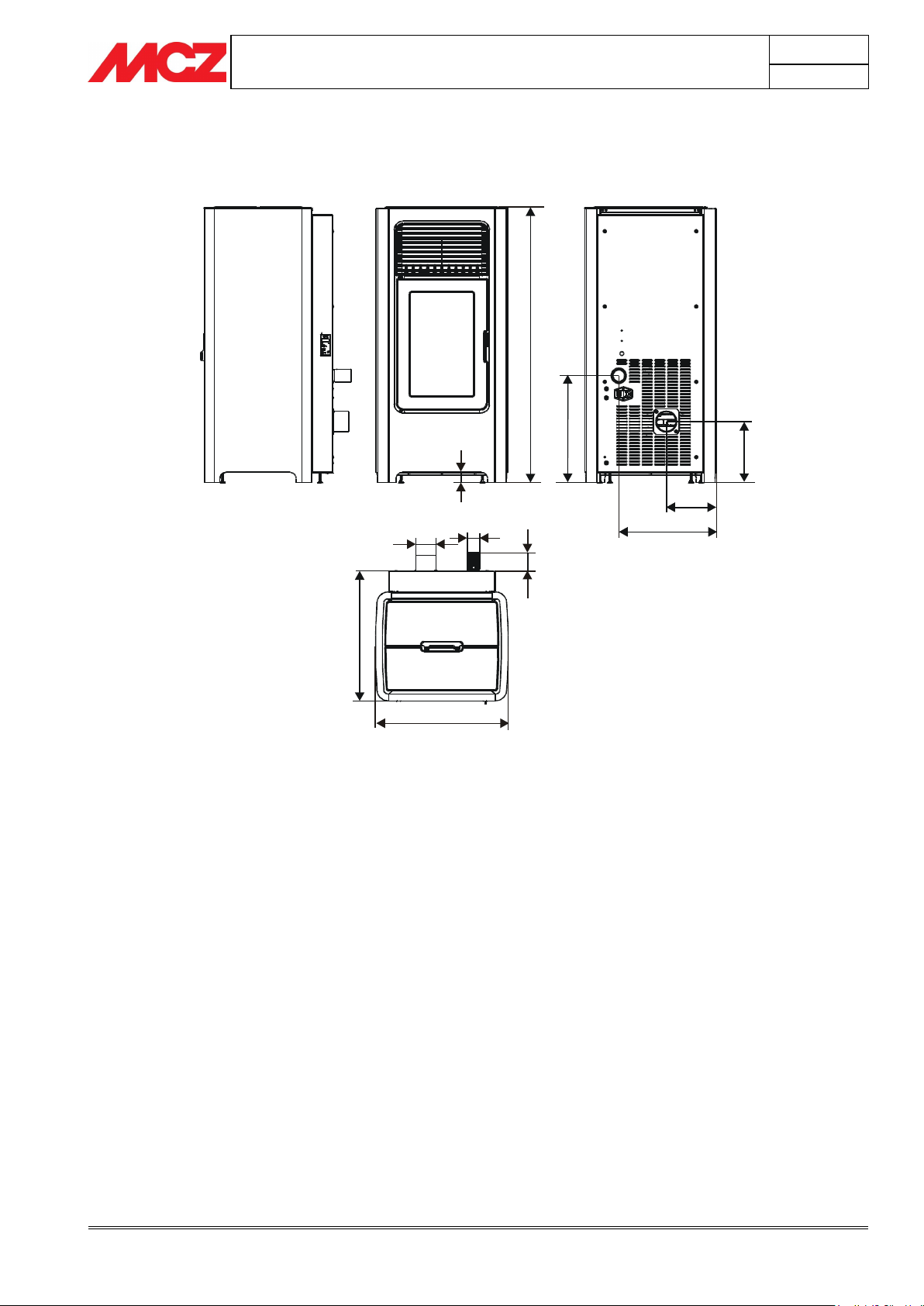
3.1.3. Dimensions MUSA mod. AIR- COMFORT AIR
3.1.4. Dimensions TOBA mod. AIR-COMFORT AIR
PELLET STOVES
Chapter 3
INSTALLATION AND USE MANUAL
page 18
Installation and assembly
Technical service - Rights reserved MCZ Group S.p.A. - Reproduction prohibited
384
197
2
4
1
4
2
1
40
1
0
8
1
522
5
1
1
7
0
Ø80
Ø48
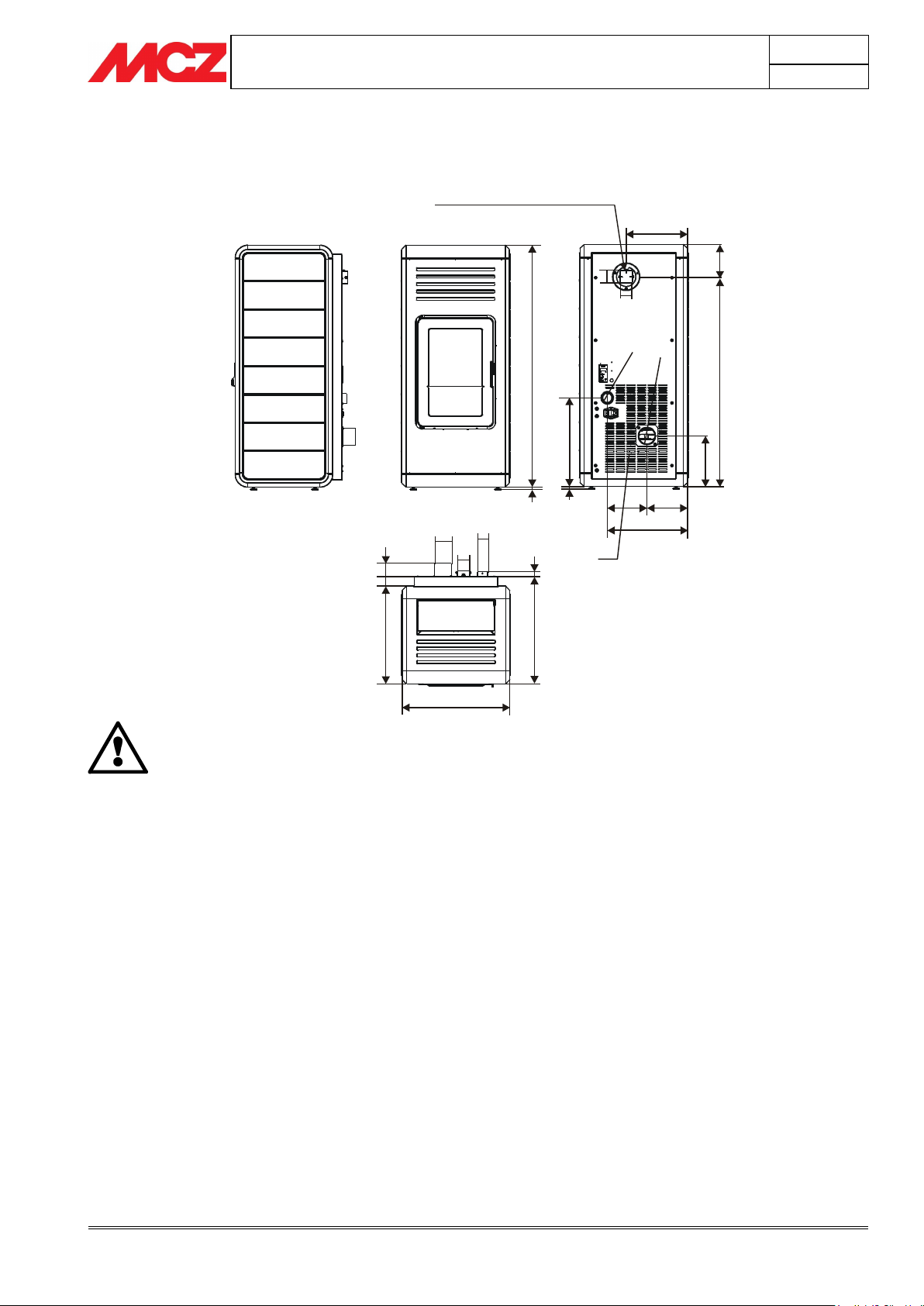
3.1.5. Dimensions SAGAR mod. AIR
PELLET STOVES
Chapter 3
INSTALLATION AND USE MANUAL
page 19
Installation and assembly
Technical service - Rights reserved MCZ Group S.p.A. - Reproduction prohibited
1
1
4
0
1
2
293
4
1
8
1
2
187 195
382
9
8
8
1
5
2
2
3
8
5
0
4
515
2
3
4
6
0
4
4
6
4
Ø80
Ø48
60
Ø
4
8
Ø
8
0
6
0
60
COMFORT AIR
HOT AIR OUTLET
COLD AIR INLET
IMPORTANT!
The hole in CLUB, SUITE, MUSA, NIMA and TOBA
stoves for hot air outlet, located at the top to the rear
of the stove, is only present for the COMFORT AIR
model.
3.1.6. Dimensions NIMA mod. COMFORT AIR

PELLET STOVES
Chapter 3
INSTALLATION AND USE MANUAL
page 20
Installation and assembly
Technical service - Rights reserved MCZ Group S.p.A. - Reproduction prohibited
Technical characteristics
CLUB – SUITE – MUSA Mod. AIR
(Max) nominal output power
9,5 kW (8170 kcal/h)
Minimum output power
2,4 kW (2064 kcal/h)
Yield at maximum
91,7%
Yield at minimum
94,1%
Temperature of exhaust smoke at maximum
180°C
Temperature of exhaust smoke at minimum
100°C
Particulate/OGC / Nox (13%O2)
22 mg/Nm3 - 5 mg/Nm3 - 123 mg/Nm3
CO at 13%O
²
at minimum and maximum
0,025 – 0,014%
CO2 at minimum and maximum
5,7% - 8,7%
Mass of smoke
7,7 g/sec
Recommended draught at Max power
0,10 mbar – 10 Pa
Recommended draught at Min power
0,05 mbar – 5 Pa
Hopper capacity
44 litri
Fuel pellet type
Pellet diametro 6-8 mm. Con pezzatura 5/30 mm.
Pellet consumption per hour
Min~0,6 kg/h* Max~2,0 kg/h*
Operating time between re-fuelling
Al min~48 h* Al max~15 h*
Heatable volume m3
204/40-233/35-272/30 **
Combustion air inlet
External diameter 50 mm.
Smoke outlet
External diameter 80 mm.
Nominal electrical power (EN 60335-1).
Max. 420 W – Med. 80 W
Power supply frequency and voltage
230 Volt / 50 Hz
Net weight
160 Kg.
Weight with packaging
170 Kg.
Technical characteristics
CLUB – SUITE – MUSA - NIMA Mod. COMFORT AIR
(Max) nominal output power
11,5 kW (9890 kcal/h)
Minimum output power
2,4 kW (2064 kcal/h)
Yield at maximum
90,2%
Yield at minimum
94,1%
Temperature of exhaust smoke at maximum
190°C
Temperature of exhaust smoke at minimum
130°C
Particulate/OGC / Nox (13%O2)
20 mg/Nm3 - 8 mg/Nm3 - 133 mg/Nm3
CO at 13%O
²
at minimum and maximum
0,025 – 0,013%
CO2 at minimum and maximum
5,7% - 8,6%
Mass of smoke
9,9 g/sec
Recommended draught at Max power
0,10 mbar – 10 Pa
Recommended draught at Min power
0,05 mbar – 5 Pa
Hopper capacity
44 litri
Fuel pellet type
Pellet diametro 6-8 mm. Con pezzatura 5/30 mm.
Pellet consumption per hour
Min~0,6 kg/h* Max~2,2 kg/h*
Operating time between re-fuelling
Al min~48 h* Al max~13 h*
Heatable volume m3
247/40-283/35-330/30 **
Combustion air inlet
External diameter 50 mm.
Smoke outlet
External diameter 80 mm.
Nominal electrical power (EN 60335-1).
Max. 420 W – Med. 100 W
Power supply frequency and voltage
230 Volt / 50 Hz
Net weight
160 Kg.
Weight with packaging
170 Kg.
3.1.7. Technical characteristics
* Data that may vary depending on the type of pellets used.
**Heatable volume based on the requested power per m3 (respectively 40-35-30 Kcal/h per m3)
Tested according to EN 14785 accordance with Directive 89/106/EEC (Construction Products).
PELLET STOVES
Chapter 3
INSTALLATION AND USE MANUAL
page 21
Installation and assembly
Technical service - Rights reserved MCZ Group S.p.A. - Reproduction prohibited
Technical characteristics
SAGAR – TOBA Mod. AIR
(Max) nominal output power
8 kW (6880 kcal/h)
Minimum output power
2.4 kW (2064 kcal/h)
Yield at maximum
91,7 %
Yield at minimum
94,1 %
Temperature of exhaust smoke at maximum
170°C
Temperature of exhaust smoke at minimum
100°C
Particulate/OGC / Nox (13%O2)
22 mg/Nm3 - 6 mg/Nm3 - 121 mg/Nm3
CO at 13%O
²
at minimum and maximum
0.025 — 0.014%
CO2 at minimum and maximum
5,7% – 8,7%
Mass of smoke
6,6 g/sec
Recommended draught at Max power
0,10 mbar – 10 Pa
Recommended draught at Min power
0,05 mbar – 5 Pa
Hopper capacity
37 litri
Fuel pellet type
Pellet diametro 6-8 mm. Con pezzatura 5/30 mm
Pellet consumption per hour
Min ~ 0,6 kg/h * Max. ~ 1,8 kg/h *
Operating time between re-fuelling
Al min ~ 40 h * Al max. ~ 13 h *
Heatable volume m3
172/40 – 196/35 – 229/30 **
Combustion air inlet
External diameter 50 mm.
Smoke outlet
External diameter 80 mm.
Nominal electrical power (EN 60335-1).
Max. 420 W – Med. 80 W
Power supply frequency and voltage
230 Volt / 50 Hz
Net weight
140 Kg.
Weight with packaging
150 Kg.
Technical characteristics
TOBA Mod. COMFORT AIR
(Max) nominal output power
8 kW (6880 kcal/h)
Minimum output power
2.4 kW (2064 kcal/h)
Yield at maximum
91,7 %
Yield at minimum
94,1 %
Temperature of exhaust smoke at maximum
170°C
Temperature of exhaust smoke at minimum
100°C
Particulate/OGC / Nox (13%O2)
22 mg/Nm3 - 5 mg/Nm3 - 123 mg/Nm3
CO at 13%O
²
at minimum and maximum
0.025 — 0.014%
CO2 at minimum and maximum
5,7% – 8,7%
Mass of smoke
6,6 g/sec
Recommended draught at Max power
0,10 mbar – 10 Pa
Recommended draught at Min power
0,05 mbar – 5 Pa
Hopper capacity
35 litri
Fuel pellet type
Pellet diametro 6-8 mm. Con pezzatura 5/30 mm
Pellet consumption per hour
Min ~ 0,6 kg/h * Max. ~ 1,8 kg/h *
Operating time between re-fuelling
Al min ~ 40 h * Al max. ~ 13 h *
Heatable volume m3
172/40 – 197/35 – 229/30 **
Combustion air inlet
External diameter 50 mm.
Smoke outlet
External diameter 80 mm.
Nominal electrical power (EN 60335-1).
Max. 420 W – Med. 80 W
Power supply frequency and voltage
230 Volt / 50 Hz
Net weight
140 Kg.
Weight with packaging
150 Kg.
* Data that may vary depending on the type of pellets used.
**Heatable volume based on the requested power per m3 (respectively 40-35-30 Kcal/h per m3)
Tested according to EN 14785 accordance with Directive 89/106/EEC (Construction Products).
 Loading...