


MANUAL FOR USE AND
INSTALLATION
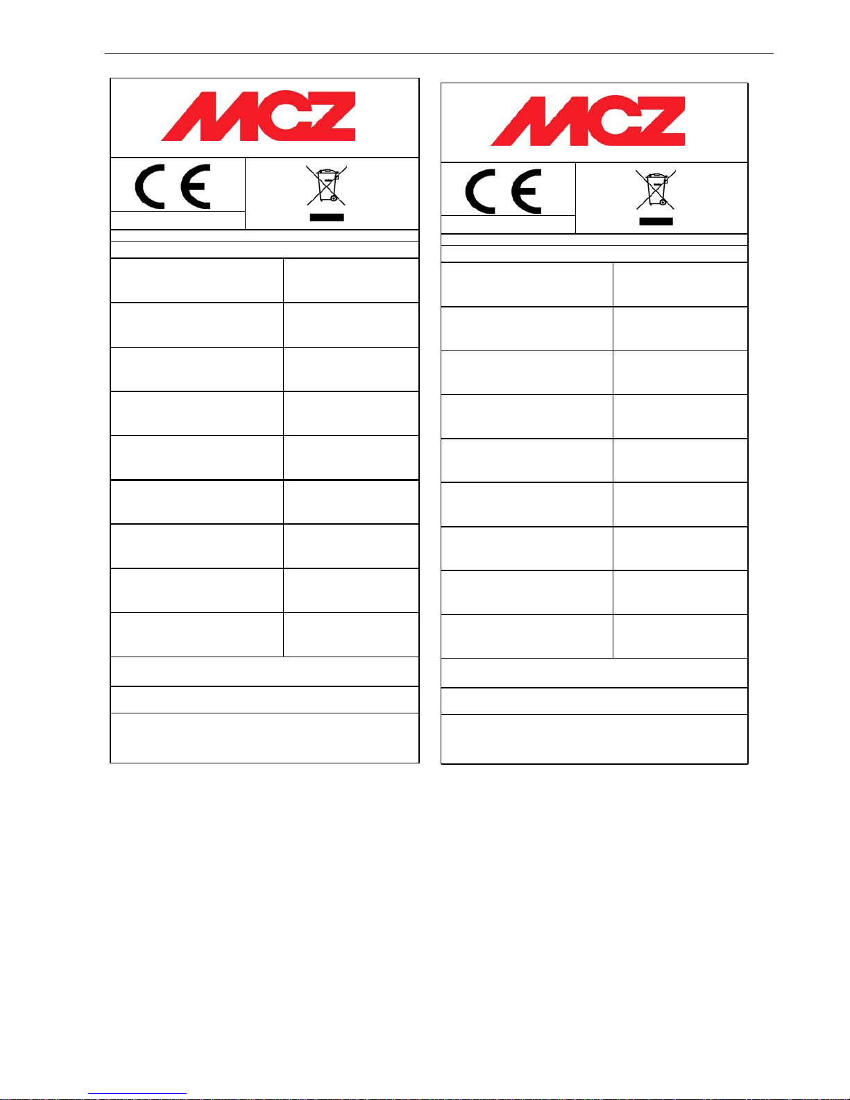
EN 14785 - 2006
Potencia nominal (agua - aire):
Potência nominal (água - ar):
Nominal heat output (water - air):
Brændværdi (vand - luft):
Emisión CO
(
al 13% de O2):
Emissão CO (13% de O2):
CO emission (at 13% O2)
CO emission (ved 13% O2):
Eficiencia:
Eficiencia:
Efficiency:
Virkningsgrad:
Temperadura humos:
Tempretura dos fumos:
Flue gas temperature:
Røggastemperatur:
Presión máxima de agua:
Pressão máxima da água:
Permissible max. water pressure:
Max. vandtryk :
A
sorbimiento electr ico max:
Max. elektrisk effekt:
Tensión de funcionamiento:
Tensão electrica funcionamento:
Rated volta
g
e:
Netspænding:
Distan cia s de segu r ida d (ret ro):
Distancia de segurança (trasiera):
Safety clarence distance (back):
Sikkerhedsafstand (bag):
Dis tan ci a s de seguridad (lat e r al es ):
Distancia de segurança (lat eral):
Safety clarence distance (side):
Sikkerhedsafstand (side):
Utilizar sólo con combu st ib les ad a ptados. Utiliza r somente combustivel adaqu ado . Use
only recommended fuels. Anvend kun anbefalede brændsler.
Leer y seguir las instrucciones! Leia atentamente e siga as instruções!
Leggere e seguire le istruzioni! Read and follow the operating
instructions! Følg fabrikantens brugervejledning!
COD: 89008010
230 V - 50 Hz.
200 mm
100 mm
Producto confor m e a la in s talació n de tubos mú ltiples. Produto co nfor m e pa r a
instalação em condutas multiplas. Appliance suitable for installation in a shared flue.
Appa rat e t kan bruges i e n r øggassaml eledning.
0,017%
0,045%
P max
P min
91,0%
94,0%
190 °C
2,5 bar
300 W
Potência electrica absorbida:
Max. electrical power supply:
MCZ S.p.A. - Via G.Oberdan 86, I - 33074 Vigonovo (PN) Italy.
07
Art. 15a B -V G - VKF AEAI
ATHOS HYDRO
Max 14,0kW (10,4kW - 3,6kW)
Min 4,0k W ( 1,4 k W - 2,6k W )
P max
P min
EN 14785 - 2006
Potencia nominal (agua - aire):
Potência nominal (água - ar ):
Nominal heat output (water - air):
Brændværdi (vand - luft):
Emisión CO
(
al 13% de O2):
Emissão CO (13% de O2):
CO emission (at 13% O2)
CO emission (ved 13% O2):
Eficiencia:
Eficiencia:
Efficiency:
Virkningsgrad:
Temperadura humos:
Tempretura dos fumos:
Flue gas tem pe ra tur e :
Røggastemperatur:
Presión máxima de agua:
Pres sã o máxim a da águ a :
Permissible max. water pressure:
Max . va n d tr yk :
Asorbimiento electrico max:
Max. elektrisk effekt:
Tensión de funcionamiento:
Tensão electrica funcionamento:
Rated volta
g
e:
Netspænding:
Distancias de seguridad (retro):
Distancia de segurança (trasiera):
Safety clarence distance (back):
Sikkerhedsafstand (bag):
Distancias de seguridad (laterales):
Distancia de segurança (lateral):
Safety clarence distance (side) :
Sikkerhedsafstand (side):
Max 23,7kW (16,2kW - 7,5kW)
Min 6,2 k W (3, 7k W - 2,5 k W)
MCZ S.p.A. - Via G.Oberdan 86, I - 33074 Vigonovo (PN) Italy.
07
Potência electrica absorbida:
500 mm
Leer y seguir las instrucciones! Leia atentamente e siga as instruções!
Leggere e segu ire le istruzi oni! R e ad and follow the operating
instructions! Følg fabrikantens brugervejledning!
Max. electr ical power supply :
320 W
COD: 89009025 00
Producto conforme a la instalación de tubos múltiples. Produto conforme para
instalação em condutas multiplas. Appliance suitable for installation in a shared flue.
Apparatet kan bruges i en røggassamleledning.
Utilizar sólo con combustibles adaptados. Utilizar somente combustivel adaquado. Use
only recommended fuels. Anvend kun anbefalede brændsler.
Art. 15a B-VG - VKF AEAI
230 V - 50 Hz.
200 mm
Polar / Nova / Athos Power HYDRO
250 °C
2,5 bar
P max
P min
0,019%
0,055%
P max
P min
92,0%
93,0%

PELLET STOVES Chapter 1
INSTALLATION AND USE MANUAL
page
3
Introduction Technical service - Rights reserved MCZ S.p.A. - Reproduction prohibited
INTRODUCTION ....................................................................................................................................5
1. WARNINGS AND GUARANTEE CONDITIONS ....................................................................................7
1.1. SAFETY INSTRUCTIONS..................................................................................................................7
1.2. OPERATING WARNINGS..................................................................................................................8
1.3. GUARANTEE CONDITIONS ..............................................................................................................9
1.3.1. Limitations...............................................................................................................................9
1.3.2. Exceptions...............................................................................................................................9
2. THEORETICAL NOTIONS FOR INSTALLATION................................................................................11
2.1. PELLETS ......................................................................................................................................11
2.2. OPERATING AREA.........................................................................................................................13
2.3. PRECAUTIONS..............................................................................................................................14
2.4. CONNECTION TO THE EXTERNAL AIR INTAKE................................................................................14
2.5. CONNECTION OF SMOKE DISCHARGE PIPE....................................................................................15
2.6. CONNECTION TO THE FLUE PIPE...................................................................................................16
2.7. CONNECTION TO AN EXTERNAL FLUE WITH INSULATED OR DOUBLE-WALL PIPE.............................16
2.8. CONNECTION TO FLUE PIPE OR SMOKE DUCT ...............................................................................16
2.9. OPERATING PROBLEMS CAUSED BY DRAUGHT DEFECTS IN THE FLUE.............................................17
2.10. PLUMBING CONNECTION...........................................................................................................18
3. INSTALLATION AND ASSEMBLY .....................................................................................................19
3.1. DRAWINGS and TECHNICAL CHARACTERISTICS.............................................................................19
3.1.1. Dimensions of POLAR-NOVA in HYDRO version with no kit for the production of domestic hot water
19
3.1.2. Dimensions of POLAR-NOVA in HYDRO version with kit for the production of domestic hot water..19
3.1.3. Dimensions of ATHOS POWER in HYDRO version with no kit for the production of domestic hot
water 20
3.1.4. Dimensions of ATHOS POWER in HYDRO version with kit for the production of domestic hot water
20
3.1.5. ATHOS HYDRO Dimensions.....................................................................................................21
3.1.6. TECHNICAL CHARACTERISTICS...............................................................................................21
3.2. PREPARATION AND UNPACKING....................................................................................................23
3.3. INSTALLATION OF CERAMIC CLADDING FOR POLAR AND NOVA......................................................24
3.3.1. Installation of upper panel ......................................................................................................24
3.3.2. Installation of lower panel.......................................................................................................24
3.3.3. Installation of side tiles...........................................................................................................24
3.3.4. Removal of sides on the ATHOS stove......................................................................................25
3.3.5. Installation of ceramic top.......................................................................................................26
3.4. PLUMBING SYSTEM CONNECTION .................................................................................................26
3.4.1. Connections to the system......................................................................................................28
3.4.2. System filling .........................................................................................................................28
3.4.3. Water characteristics..............................................................................................................28
3.5. EXAMPLE INSTALLATION DIAGRAMS .............................................................................................29
3.5.1. Heating installation diagram Heating system installation diagram without water kit (POLAR-NOVA-
ATHOS POWER)..................................................................................................................................30
3.5.2. Heating installation diagram with domestic hot water kit (POLAR–NOVA-ATHOS POWER).............30
3.5.3. Diagram for installation combined with external boiler (POLAR-NOVA-ATHOS POWER).................31
3.5.4. Heating installation diagram in combination with a boiler (POLAR-NOVA-ATHOS-ATHOS POWER).31
3.5.5. Heating installation in combination with a storage tank (POLAR-NOVA-ATHOS-ATHOS POWER)....32
3.6. OPENING/CLOSING OF ATHOS STOVE DOOR..................................................................................32
3.7. MAKING THE ELECTRICAL CONNECTIONS.....................................................................................32
4. OPERATION.....................................................................................................................................33
4.1. PRE-LIGHTING WARNINGS............................................................................................................33
4.2. PRE-LIGHTING CHECK ..................................................................................................................34
4.3. LOADING THE PELLETS.................................................................................................................34
4.4. CONTROL PANEL..........................................................................................................................34

PELLET STOVES Chapter 1
INSTALLATION AND USE MANUAL
page
4
Introduction Technical service - Rights reserved MCZ S.p.A. - Reproduction prohibited
4.5. SETTINGS TO CARRY OUT BEFORE FIRST LIGHTING......................................................................35
4.5.1. SETTING CURRENT TIME........................................................................................................35
4.6. SELECTION OF RECIPE .................................................................................................................35
4.6.1. OPERATIONS FOR IDENTIFICATION OF THE RECIPE:...............................................................35
4.6.1.1. Identification of type of pellet...........................................................................................36
4.6.2. Procedure for recipe selection .................................................................................................36
4.6.3. Memorization of recipe on stove.............................................................................................. 36
4.7. CONTROL OF WATER TEMPERATURE IN BOILER ............................................................................37
4.8. FIRST LIGHTING ..........................................................................................................................37
4.8.1. Lighting the stove...................................................................................................................37
4.8.2. Extinguishing the stove...........................................................................................................38
4.9. VIEW OF THE FLAMES ..................................................................................................................38
4.9.1. The shape .............................................................................................................................38
4.9.2. The colour.............................................................................................................................39
4.9.3. The character ........................................................................................................................39
4.10. OPERATION..............................................................................................................................39
4.10.1. Operating concept...............................................................................................................39
4.10.2. Operating modes ................................................................................................................40
4.10.2.1. Internal thermostat - Position of internal room sensor........................................................41
4.10.2.2. Operation by means of external thermostat.......................................................................41
4.10.2.3. Connection of external thermostat....................................................................................41
4.10.3. Setting of ECO-STOP mode..................................................................................................41
4.10.3.1.
Activation /de-activation of ECO-STOP mode
..................................................................... 43
4.10.3.2. OPERATION TO BE CARRIED OUT BY THE INSTALLER.......................................................43
4.10.4. Programmed mode (with timer) ........................................................................................... 43
4.10.4.1.
Start day (code on display UT 01)
..................................................................................... 43
4.10.4.2.
Clock (code on display UT 02 and UT 03)
.......................................................................... 44
4.10.4.3.
Programme
..................................................................................................................... 45
4.11. EXAMPLE OF PROGRAMMING.....................................................................................................47
4.12. SAFETY DEVICES.......................................................................................................................49
4.12.1. Alarm signalling ..................................................................................................................51
4.12.2. Other signals on the display.................................................................................................52
4.12.3. Lockout of the stove............................................................................................................52
4.12.3.1.
Boiler bulb thermostat
..................................................................................................... 52
4.12.3.2.
Pellet hopper safety thermostat
........................................................................................ 53
4.12.3.3.
Smoke expulsion
............................................................................................................. 53
4.13. SHUTTING THE STOVE DOWN ...................................................................................................53
4.14. DOMESTIC WATER PRODUCTION KIT (optional) For POLAR-NOVA-ATHOS POWER stoves only.......54
5. MAINTENANCE AND CLEANING ......................................................................................................55
5.1. CLEANING TO BE PERFORMED BY THE USER..................................................................................55
5.1.1. Cleaning prior to each lighting.................................................................................................55
5.1.2. Check every 2/3 days .............................................................................................................55
5.1.3. Cleaning the glass..................................................................................................................55
5.1.4. Cleaning the heat exchanger and the pipe unit .........................................................................56
5.1.5. Cleaning of stainless steel and satin-finish surfaces...................................................................56
5.1.6. Cleaning of painted parts........................................................................................................56
5.2. CLEANING TO BE PERFORMED BY SPECIALIZED TECHNICIAN..........................................................57
5.2.1. Cleaning of the heat exchanger...............................................................................................57
5.2.2. Shutting the stove down (end of season) .................................................................................57
5.3. CHECK OF INTERNAL COMPONENTS..............................................................................................58
6. PROBLEMS / CAUSES / SOLUTIONS ...............................................................................................59
7. ELECTRICAL DIAGRAMS .................................................................................................................62
7.1. ELECTRICAL DIAGRAM OF POLAR-NOVA-ATHOS POWER Hydro WITH NO DOMESTIC HOT WATER KIT
62
7.2. ELECTRICAL DIAGRAM OF POLAR-NOVA-ATHOS POWER Hydro WITH DOMESTIC HOT WATER KIT....63
7.3. WIRING DIAGRAM for ATHOS Hydro without DOMESTIC HOT WATER KIT........................................64

PELLET STOVES Chapter 1
INSTALLATION AND USE MANUAL
page
5
Introduction Technical service - Rights reserved MCZ S.p.A. - Reproduction prohibited
INTRODUCTION
Dear Customer,
We would like to thank you for selecting MCZ products, and particularly
for choosing one of the MCZ Pellet range.
We are convinced that as you use it, you will appreciate the quality of
the MCZ pellet line, which is the result of careful planning and
meticulous testing. Our aim is to combine technological complexity with
simplicity of use and, above all, with safety.
In order to get the best performance from your stove and to
enjoy to the fullest the warmth and the sense of well-being
which the flame will spread through the home, we recommend
that you read this booklet carefully before lighting the stove
for the first time.
Once you have learnt the basics, you will be able manage to best
advantage the various levels of power and the potential for presetting,
and you will also pick up a few little hints about cleaning and setting.
While thanking you again, may we remind you that the stove MUST
NOT be used by children, and that they must always be kept at a safe
distance from it!
Revisions to the publication
In order to improve the product, to keep this publication up to date the
manufacturer reserves the right to make modifications without any
advance notice.
Any reproduction, even in part, of this manual without the consent of
the manufacturer is prohibited.
Care of the manual
• Take good care of this manual and keep it in a place which can
easily and quickly be reached.
• If this manual should be lost or destroyed, or if it is in poor
condition, ask for a copy from your retailer or directly from the
manufacturer, providing product identification data.
How to read the manual
• Information which is essential or that requires special attention is
shown in bold text.
•
“Italic text”
is used to direct the user's attention to explanatory
figures, or to ask the user to refer to other sections of the manual
for a more detailed explanation.
• NOTE: a NOTE provides the reader with additional information on
a specific topic.
PELLET STOVES Chapter 1
INSTALLATION AND USE MANUAL
page
6
Introduction Technical service - Rights reserved MCZ S.p.A. - Reproduction prohibited
These symbols indicate specific messages included
in this booklet
ATTENTION:
This warning sign, used at various points in this booklet,
indicates that the message to which it refers should be
carefully read and understood, because failure to comply
with what these notices say can cause serious
damage to the stove and put the user's safety at risk.
INFORMATION:
This symbol is intended to highlight information important
for the proper functioning of the stove. Failure to comply
with what these notices say will compromise the use of the
stove and is likely to result in unsatisfactory operation.
OPERATING SEQUENCES:
Indicates a sequence of buttons to be pushed to access
menus or to make adjustments.
SEE MESSAGES:
This symbol instructs the user to see the messages shown
on the control display.
PELLET STOVES Chapter 1
INSTALLATION AND USE MANUAL
page
7
Warnings and guarantee conciliations Technical service - Rights reserved MCZ S.p.A. - Reproduction prohibited
1. WARNINGS AND GUARANTEE CONDITIONS
1.1. SAFETY INSTRUCTIONS
• Installation of the stove, making the electrical
and plumbing connections, checking its
operation, and maintenance are all tasks which
should be carried out ONLY by qualified and
authorised personnel.
• Install the stove in accordance with the
regulations in force in your local area, region and
country.
• For the correct use of the stove and of the electronic
apparatus connected to it, and to prevent accidents, the
instructions given in this booklet must always be
followed.
• In addition, adjustment and regulation must be carried
out by adults. Errors or incorrect settings can give rise
to hazardous conditions and/or bad running.
• Before beginning any operation, the user, or whoever is
preparing to operate on the stove, must have read and
understood the entire contents of this instruction
booklet.
• The stove is to be used only for its intended purpose.
Any other use is to be considered improper and
therefore hazardous.
• Do not use the stove for standing on or as any kind of
support.
• Do not put clothes to dry on the stove Any clothes
hangers and the like must be kept a suitable distance
from the stove. Danger of fire.
• All responsibility for improper use is taken entirely by
the user. Such use relieves MCZ of any civil or criminal
responsibility.
• Any kind of tampering or unauthorised substitution of
non-original spare parts can be hazardous for the safety
of the operator and relieves MCZ of any civil or criminal
responsibility.
• Most of the surfaces of the stove are extremely
hot (the door, the handle, the glass, smoke
discharge pipes etc.). Avoid coming into contact
with these parts, therefore, without adequate
protective clothing or suitable implements, such
as gloves with thermal protection or implements
which keep the hands cool.
• Carefully explain this hazard to elderly people, disabled
people and particularly to all children, keeping them
away from the stove while it is in operation.
• Under no circumstances should the stove be
operated with the door open or the glass broken.
• Do not touch the stove with wet hands, in view of the
fact that it is an electrical appliance. Always disconnect
the supply cable before doing anything to the unit.
• Before carrying out any cleaning or maintenance

PELLET STOVES Chapter 1
INSTALLATION AND USE MANUAL
page
8
Warnings and guarantee conciliations Technical service - Rights reserved MCZ S.p.A. - Reproduction prohibited
operation, make sure in advance that the stove is
disconnected from the mains electricity supply, by
turning off the main switch located on the back of the
stove, or by unplugging the supply cable.
• The stove must be connected to an electrical system
which is equipped with an earth conductor, as set forth
in directives 73/23 EEC and 93/98 EEC.
• The system must be of adequate rated capacity for the
stated electrical power of the stove.
• Incorrect installation or faulty maintenance (not
conforming to the requirements set out in this booklet)
can cause harm to people, animals or property. In such
cases MCZ is relieved of any civil or criminal
responsibility.
1.2. OPERATING WARNINGS
• Shut the stove down in the event of a breakdown or
bad running.
• Pellets must not be fed manually into the burner.
• Accumulated unburnt pellets in the burner after
repeated failed ignitions must be removed
before lighting.
• Do not wash the inside of the stove with water.
• Do not wash the stove with water. The water could get
inside the unit and damage the electrical insulation and
cause electric shocks.
• Do not expose your body to hot air for extended
periods. Do not overheat the room you are in and
where the stove is installed. This could cause injuries
and health problems.
• Do not expose plants or animals directly to a current of
hot air. Both plants and animals could be harmed by it.
• Do not put anything in the hopper other than wood
pellets.
• Install the stove in a location which is suitable for for
fire protection, and equipped with all services such as
air and electricity supply and provision for discharging
combustion gases.
• If there is a fire in the flue pipe, extinguish the stove,
disconnect it from the power supply and never open
the door. Then contact the competent authorities.
• If the stove and the ceramic cladding are in storage, it
should be in a place that is free of damp, and they
should not be exposed to extremes of temperature.
• It is inadvisable to base the stove directly on the floor,
and if the floor is made of flammable material, it must
be suitably insulated.
• Do not light the stove with flammable materials if the
ignition system breaks down.

PELLET STOVES Chapter 1
INSTALLATION AND USE MANUAL
page
9
Warnings and guarantee conciliations Technical service - Rights reserved MCZ S.p.A. - Reproduction prohibited
INFORMATION
• In case of any problems, get in touch with your dealer,
or qualified personnel authorised by MCZ. If repair is
necessary, insist on the use of original spare parts.
• Use only the fuel recommended by MCZ (for Italy pellets
with a diameter of 6 mm and for other European
countries with a diameter of 6-8 mm) and provided only
with an automatic supply system.
• Periodically check and clean the smoke outlet ducts
(connection to the flue pipe).
• Accumulated unburnt pellets in the burner after
repeated failed ignitions must be removed before
lighting.
• The pellet stove is not a cooking appliance.
• Always keep the cover of the fuel hopper closed.
• Keep this instruction manual carefully because it must
stay with the stove throughout its working life. If the
stove is sold or transferred to another user, always
make sure that the booklet goes with the product.
• If it gets lost, ask MCZ or your authorised dealer for
another copy.
1.3. GUARANTEE CONDITIONS
MCZ guarantees the stove, excluding the components
which are subject to normal wear, for a period of two
years from the date of purchase, as proved by a supporting
document which gives the name of the vendor and the date
on which the sale took place. The guarantee is conditional
on the guarantee certificate being filled in and returned
within 8 days, and requires that the product be installed
and tested by a specialised installer, according to the
detailed instructions given in the instruction booklet
supplied with the product.
The term 'guarantee' is to be understood to denote the
free-of-charge replacement or repair of parts recognised
to have been defective at the start by reason of
manufacturing defects.
1.3.1. Limitations
The above guarantee does not cover components relating to electrical
and electronic parts, or fans, on which the guarantee period is 1 year
from the purchase of the product, documented as specified above. The
guarantee does not cover parts subject to normal wear such as
gaskets, glass, and any parts with can be removed from the firebox.
The replacement parts will be guaranteed for the remainder of the
guarantee period starting from the date of purchase of the product.
1.3.2. Exceptions
Variations in colour in the painted or ceramic parts, and crackling of the
glaze on the ceramics, do not constitute grounds for a claim under the
guarantee, as they are natural characteristics of the material and of the
use of the product.
PELLET STOVES Chapter 1
INSTALLATION AND USE MANUAL
page
10
Warnings and guarantee conciliations Technical service - Rights reserved MCZ S.p.A. - Reproduction prohibited
The guarantee does not cover any parts which may be found to be
faulty as a result of negligence or carelessness in use, or of incorrect
maintenance, or of installation not complying with MCZ's specification
(see the relevant chapters in this user manual).
MCZ refuses to accept any responsibility for any damage which may be
caused, directly or indirectly, by persons, animals or things as a result
of the failure to observe all the prescriptions laid down in the
instruction booklet, especially those concerning warnings on the subject
of installation, use and maintenance of the appliance.
If the product does not perform correctly, contact your local retailer
and/or importer.
Damage caused by transport and/or handling is excluded from the
guarantee.
For installation and use of the product, reference must be made
exclusively to the booklet supplied.
The guarantee will be invalidated in the event of damage caused by
tampering with the appliance, atmospheric agents, natural disasters,
electrical discharges, fire, defects in the electrical system, and lack of,
or incorrect, maintenance in terms of the manufacturer's instructions.
CLAIMS UNDER THE GUARANTEE
The request for action under the guarantee must be
addressed to the retailer, who will forward the claim
to MCZ's technical assistance service.
MCZ DECLARES THAT THE STOVE WHICH YOU HAVE
PURCHASED COMPLIES WITH EEC DIRECTIVE
89/336 AND 72/23 AND SUBSEQUENT
AMENDMENTS.
MCZ shall not be held liable if the stove or any other
accessory have been improperly used or modified
without authorisation.
For all replacement of parts, only original MCZ spare
parts must be used.
PELLET STOVES Chapter 2
INSTALLATION AND USE MANUAL
page
11
Theoretical notions for installation Technical service - Rights reserved MCZ S.p.A. - Reproduction prohibited
2. THEORETICAL NOTIONS FOR INSTALLATION
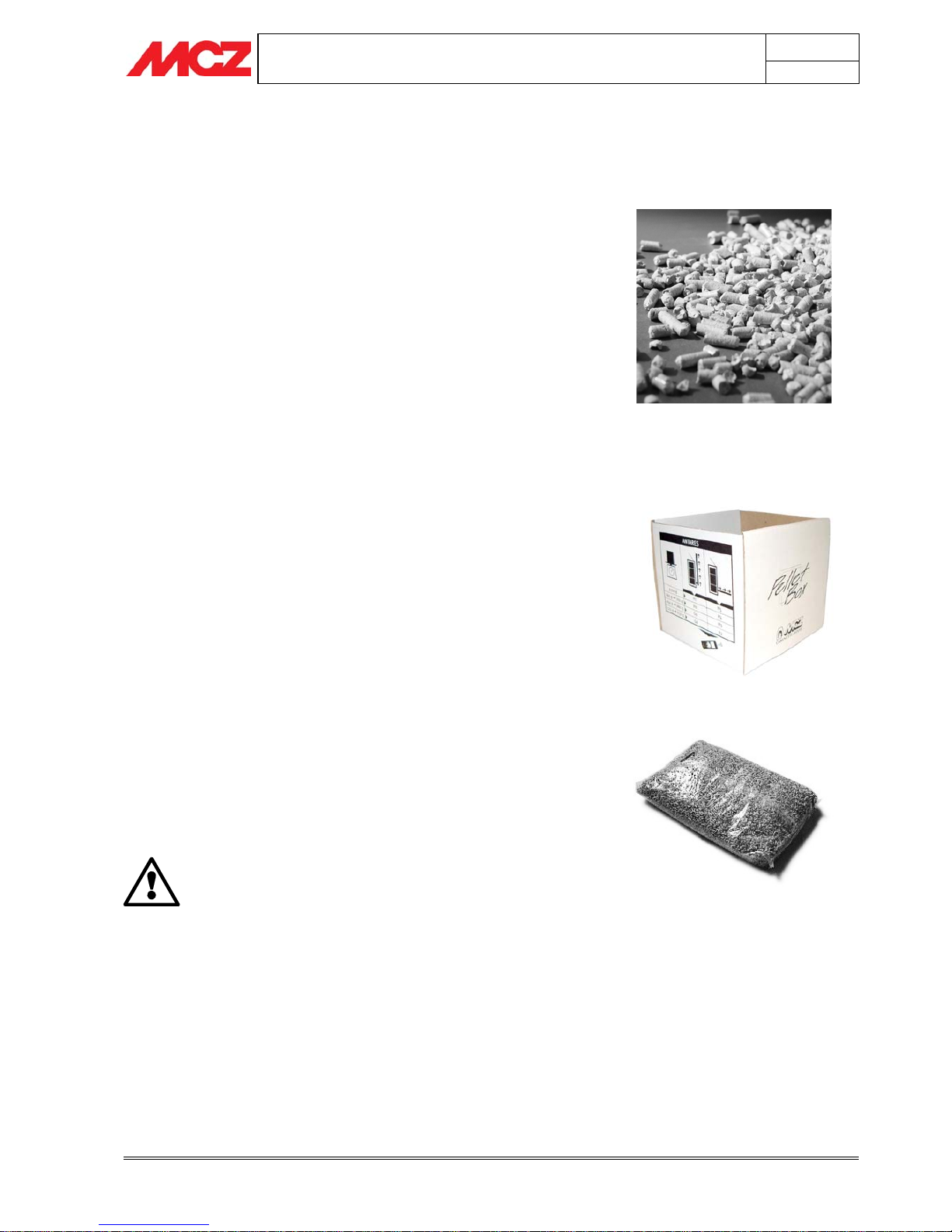
2.1. PELLETS
Wood pellets are manufactured by hot-extruding compressed sawdust
which is produced during the working of natural dried wood. The
compactness of the material comes from the lignin which is contained
in the wood itself, and allows the production of pellets without the use
of glues or binders.
The market offers different types of pellet with characteristics which
vary depending on what mixture of woods is used. The diameter varies
between 6 mm and 8 mm, with a standard length in the range 5 mm to
30 mm. Good quality pellets have a density which varies between 550
kg/m
3
to over 700 kg/m3, with a moisture content which varies from
5% to 8% by weight.
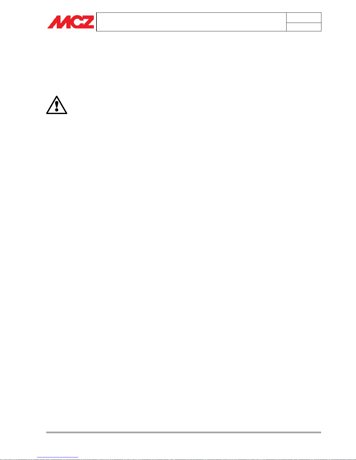
With the aim of guaranteeing the stated rate of fuel
consumption per hour and ensuring optimum combustion, MCZ
has devised a patented method which allows the identification
and cataloguing of any type of pellet with a 6 mm and 8 mm
diameter, in terms of its specific gravity and particle size.
By using the special PelletBox® and following the procedure set out in
the paragraph on lighting the stove, the user can determine the correct
settings for configuring the stove.
Besides being an ecological fuel (exploiting timber residues to the
maximum and achieving cleaner combustion than is possible with fossil
fuels), pellets also have technical advantages. While good-quality
timber has a calorific power of 4.4 kW/kg (with 15% moisture, after
about 18 months' seasoning), the equivalent figure for pellets is 5.3
kW/kg.
To ensure good combustion, the pellets must be stored in an area that
is free of humidity and protected from dirt. The pellets are usually
supplied in 15 kg. sacks, so storing them is very convenient.
Good quality pellets ensure good combustion, thus lowering the
emission of harmful agents into the atmosphere.
The poorer the quality of the fuel, the more
frequently will intervention be necessary for cleaning
the internal parts, such as the grate and the
combustion chamber.
The pellets must be produced from pure wood which has not been
treated chemically.
The standards DIN 51731 and ONORM M 7135 certify a high-quality
pellet with the following characteristics:
9 Calorific power: 5.3 kW/kg
9 Density: 700 kg/m
3
9 Water content: max 8% of weight
9 Percentage of ashes: max 1% of weight
Figure 1 - Pellet fuel
Figure 2 - PelletBox®
Figure 3 - Sack of fuel, 15 kg
PELLET STOVES Chapter 2
INSTALLATION AND USE MANUAL
page
12
Theoretical notions for installation Technical service - Rights reserved MCZ S.p.A. - Reproduction prohibited
9 Diameter: 6 – 6.5mm
9 Length: max 30mm
9 Contents: 100% untreated wood, with no added bonding
substances (bark percentage 5% max)
9 Packaging: in sacks made from ecologically compatible or
biologically decomposing material
MCZ strongly recommends using certified fuel in its
stoves.
The use of fuel of inferior quality or not conforming
to the specification given above compromises the
running of your stove and can therefore lead to the
termination of the guarantee and of the
manufacturer's responsibility for the product.
MCZ pellet stoves run exclusively on pellets with a
diameter of 6 mm (only for Italy) and 6-8 mm
(European countries) with lengths that go from 5
mm to 30 mm.
PELLET STOVES Chapter 2
INSTALLATION AND USE MANUAL
page
13
Theoretical notions for installation Technical service - Rights reserved MCZ S.p.A. - Reproduction prohibited
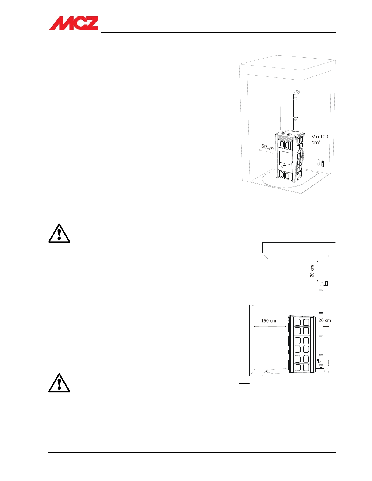
2.2. OPERATING AREA
For proper functioning and good temperature distribution, the stove
should be positioned in a location where it is able to take in the air
necessary for combustion of the pellets (about 40 m
3
/h must be
available), as set forth in the standard governing the installation and in
accordance with local national standards.
The volume of the room must not be less than 30 m
3
.
The air must come in through permanent openings made in walls (in
proximity to the stove) which give onto the outside, with a minimum
cross-section area of 100 cm
2
.
These openings must be made in such a way that it is not possible for
them to be obstructed in any way.
Alternatively, the air can be taken from rooms adjacent to the one
which needs ventilating, as long as they are provided with an air intake
from the outside, and are not used as bedrooms or bathrooms, and
provided there is no fire risk such as there is for example in garages,
woodsheds, and storerooms, with strict compliance with the provisions
of current standards.
It is not permissible to install the stove in bedrooms,
bathrooms or showers, or in a room where another
heating appliance is installed (fireplace, stove etc.)
which does not have its own independent air intake.
Locating the stove in a room with an explosive
atmosphere is prohibited.
The floor of the room where the stove is to be
installed must be strong enough to support its
weight.
If the walls are not flammable, position the stove with a clearance to
the rear of at least 10 cm.
In the case of walls made of flammable material, maintain a minimum
clearance to the rear of 20 cm, a clearance to the sides of 50 cm, and a
clearance to the front of 150 cm. If the room contains objects which
are believed to be particularly delicate, such as curtains, sofas and
other furniture, their distance from the stove should be considerably
increased.
If the flooring is made of wood, provide a floor
protection surface in compliance with current
national standards.
Figure 4 - Example of installation with Polar stove
Figure 5 - Example of installation with Polar stove
PELLET STOVES Chapter 2
INSTALLATION AND USE MANUAL
page
14
Theoretical notions for installation Technical service - Rights reserved MCZ S.p.A. - Reproduction prohibited
2.3. PRECAUTIONS
IMPORTANT!
Installation and assembly of the stove must be
carried out by qualified personnel.
The stove must be installed in a suitable position to allow the normal
operations of opening and ordinary maintenance.
The site must be:
• capable of providing the environmental conditions for operation
• equipped with power supply 230V 50 Hz (EN73-23)
• capable of taking an adequate system for smoke discharge
• provided with external ventilation
• provided with an earth connection complying with CEI 64-8
The stove must be connected to a flue pipe or an internal or
external vertical duct conforming to current standards UNI
7129 - 7131 9615.
The stove must be positioned in such a way that the electrical
plug is accessible.
IMPORTANT!
The stove must be connected to a flue pipe or a
vertical duct which can discharge the fumes at the
highest point of the building.
The fumes are however derived from the combustion
of wood products, and if they come into contact with
or close to walls, they can make dirty marks.
Also take care because the fumes are very hot but
almost invisible, and can cause burns on contact.
The holes for the passage of the smoke pipe and for
the intake of air from outside should be made before
positioning the stove unit.
2.4. CONNECTION TO THE EXTERNAL AIR INTAKE
It is essential that at least as much air must be able to flow into the
room where the stove is installed as is required for proper combustion
in the appliance and for the ventilation of the room. This can be
effected by means of permanent openings in the walls of the room to
be ventilated, which give onto the outside, or by single or collective
ventilation conduits.
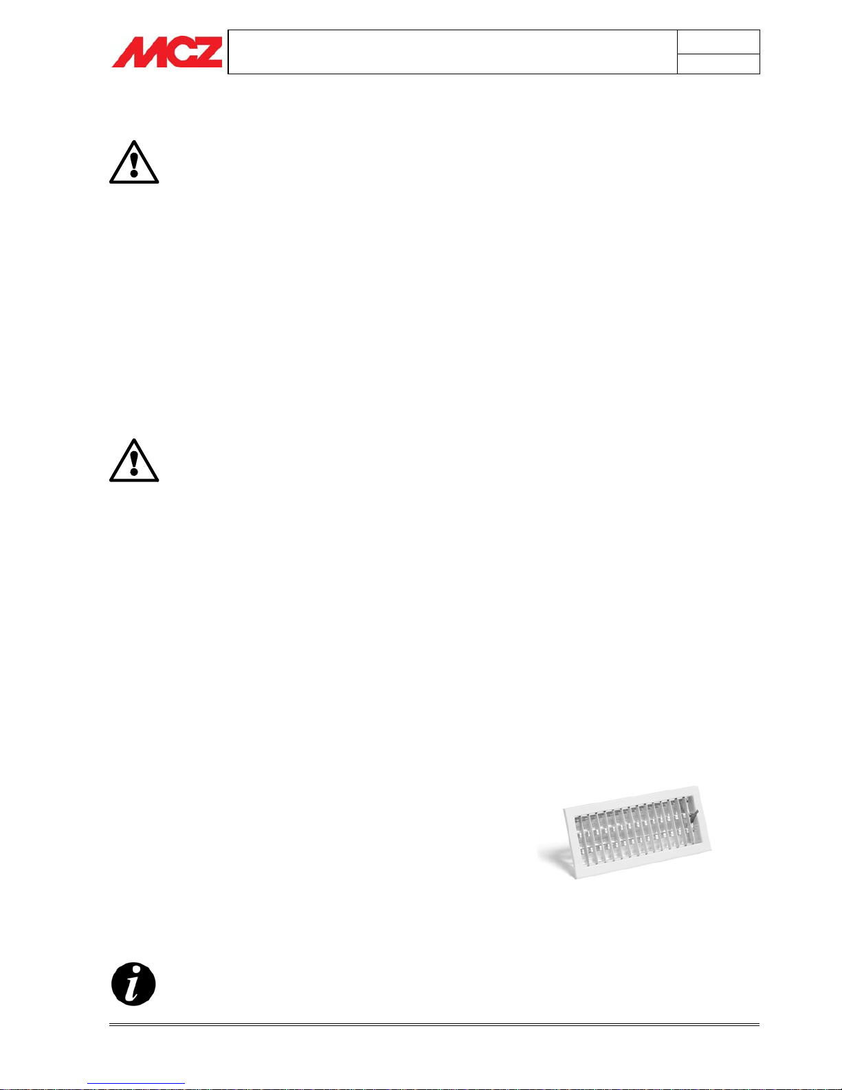
For this purpose, on the external wall near the stove, a hole must be
made with a minimum free cross-section of 100 cm². (equivalent to a
round hole of 12 cm diameter or a square hole 10x10 cm), protected by
a grille on the inside and the outside.
The air intake must also:
• communicate directly with the room where the stove is installed
• be protected by a grille, metal mesh or suitable guard, as long as
this does not reduce the cross-section below the minimum.
• be positioned in such a way as to be impossible to obstruct
It is not compulsory to connect the air inlet of the
stove directly with the exterior, but an air flow must
be guaranteed of at least 50 m³/h. Refer to current
standards.
Figure 6 – Air intake grille
PELLET STOVES Chapter 2
INSTALLATION AND USE MANUAL
page
15
Theoretical notions for installation Technical service - Rights reserved MCZ S.p.A. - Reproduction prohibited
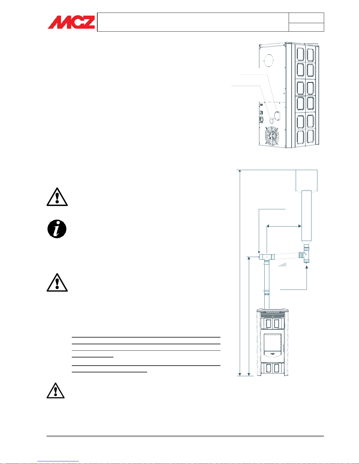
2.5. CONNECTION OF SMOKE DISCHARGE PIPE
When making the hole for the passage of the smoke discharge pipe, it
is necessary to take into account the possible presence of flammable
materials. If the hole will be going through a wall made of wood or any
other material which is sensitive to heat, the INSTALLER MUST first
of all use the special wall union (diam. 13cm minimum) and properly
insulate the pipe of the stove that passes through it, using adequate
insulation materials (thickness 1.3 - 5cm with minimum thermal
conductivity of 0.07 W/m°K).
The same is true if the stove pipe must run through vertical or
horizontal stretches passing in proximity (min. 20cm) to the heatsensitive wall.
As an alternative we recommend the use of insulated pipe, which can
also be used on the outside to avoid condensation.
The combustion chamber works in low pressure. The smoke duct for
the discharge of fumes will also be under low pressure when connected
to an efficient flue pipe as directed.
Pipes and unions with suitable gaskets must always
be used, to guarantee a hermetic seal.
All sections of the smoke duct must be inspectable and
removable to enable periodic internal cleaning. Tee
connectors with inspection caps should be used.
Position the stove bearing in mind all the instructions and
considerations above.
IMPORTANT!
All 90 degree changes of direction in the flue pipe
must be fitted with suitable tee connectors to allow
the possibility of inspection (see the pellet stove
accessory list).
It is absolutely prohibited to fit a grille on the end of
the smoke discharge pipe, because it could lead to
poor operation of the stove.
FOR CONNECTION TO THE FLUE PIPE, NOT MORE
THAN 2-3 METRES OF HORIZONTAL PIPE MUST BE
USED AND NOT MORE THAN THREE 90° CURVES
MUST BE USED
NOT ADVISABLE TO EXCEED A LENGTH OF 6 LINEAR
METRES OF PIPE Ø 80 mm.
THE DIRECT DISCHARGE OF THE
COMBUSTION PRODUCTS MUST BE
PROVIDED ON THE ROOF, AND THE SMOKE
DUCT MUST SATISFY THE SPECIFICATIONS
PROVIDED FOR BY CURRENT LAWS AND
STANDARDS ON THE SUBJECT (UNI 10683)
Figure 7 – Back of POLAR/NOVA stove
Figure 8 – Example of installation of POLAR/NOVA stove
Air intake
Smoke outlet
3-5 %
2 - 3 mt. MAX
Ispection cover
M
i
n
1
,
5
-
2
m
t
H
e
i
g
h
t
g
r
e
a
t
e
r
t
h
e
n
4
m
t
.
Ispection cover
PELLET STOVES Chapter 2
INSTALLATION AND USE MANUAL
page
16
Theoretical notions for installation Technical service - Rights reserved MCZ S.p.A. - Reproduction prohibited
Ispezione
Condotto
esterno
isolato
0,5 mt.
3-5 %
2 - 3 mt. MAX
Minimo 1,5 - 2 mt.
Ispezione
0, 5 mt.
Canna fumaria
Comignolo
antivento
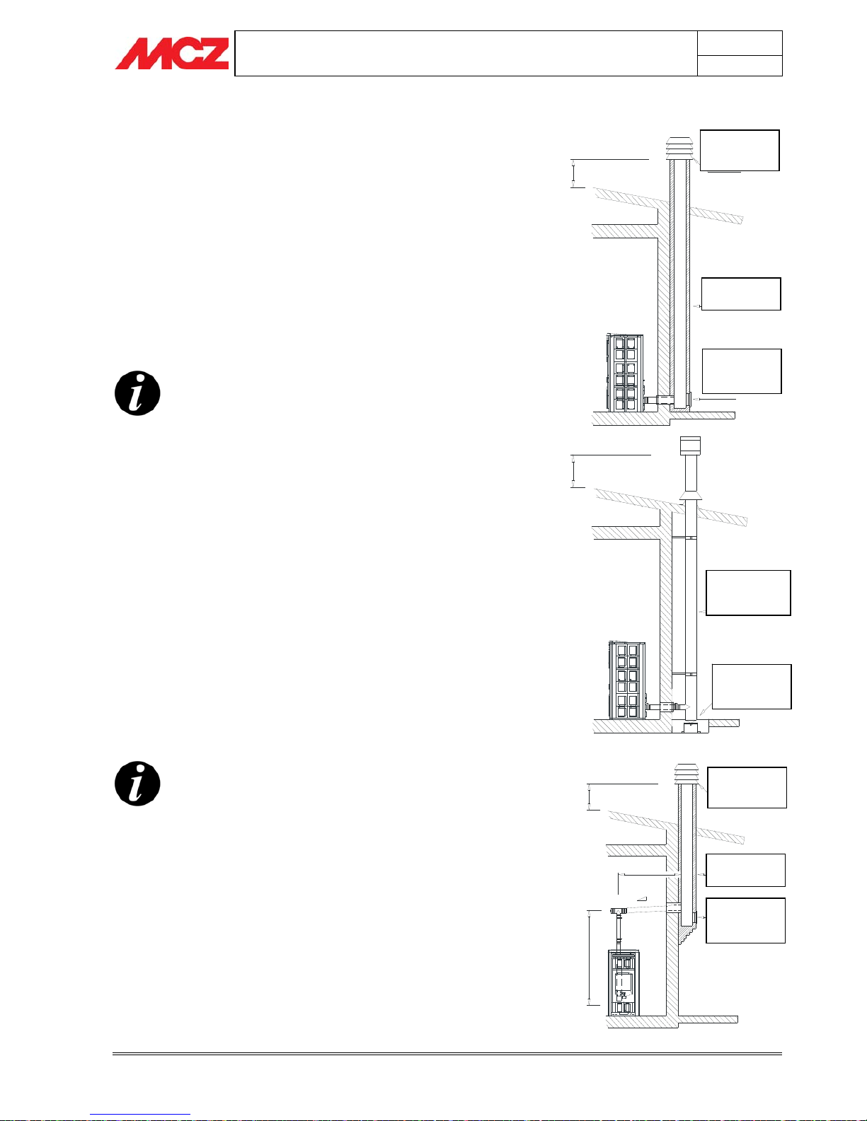
2.6. CONNECTION TO THE FLUE PIPE
The flue pipe must have internal dimensions not larger than 20 x 20
cm, or diameter 20 cm. In the event of larger dimensions, or of the flue
pipe being in poor condition (for example cracks, poor insulation, etc.),
it is advisable to fit a stainless steel pipe of suitable diameter inside the
flue pipe throughout its length, right up to the top.
Figure 9
Check with suitable instruments that there is a minimum draught of 10 Pa.
At the bottom of the flue pipe, provide an inspection cap to allow
periodic checking and cleaning, which must be done annually.
Make a gas-tight connection to the flue pipe, using pipes and
connectors as recommended by us.
You must ensure that a windproof cowl is fitted which complies with
current standards.
This type of connection ensures the evacuation of the
fumes even in the event of a temporary power
outage.
2.7. CONNECTION TO AN EXTERNAL FLUE WITH
INSULATED OR DOUBLE-WALL PIPE
The external fluepipe must have internal dimensions of minimum 10x10
cm or 10 cm diameter, and maximum 20x20 cm or 20 cm diameter.
Check with suitable instruments that there is a minimum draught of 10 Pa.
Figure 10
The only type of pipe which is permissible is insulated (double-walled)
stainless steel, smooth on the inside, fixed to the wall. Flexible stainless
steel pipe must not be used.
At the bottom of the flue pipe, provide an inspection cap to allow
periodic checking and cleaning, which must be done annually.
Make a gas-tight connection to the flue pipe, using pipes and
connectors as recommended by us.
You must ensure that a windproof cowl should be fitted which complies
with the standards in force.
This type of connection ensures the evacuation of the
fumes even in the event of a temporary power cut.
2.8. CONNECTION TO FLUE PIPE OR SMOKE DUCT
For proper operation, the connection between the stove and the flue
pipe or smoke duct must have a slope of not more than 3%. The length
of the horizontal segment must not exceed 2/3 m. and the vertical
distance between one tee connector and another (change of direction)
must not be less than 1.5m.
Check with suitable instruments that there is a minimum draught of 10 Pa.
Figure 11
At the bottom of the flue pipe, provide an inspection cap to allow
periodic checking and cleaning, which must be done annually.
Figure 9
Figure 10
Figure 11
Canna fumaria
Comignolo
antivento
Ispezione
0,5 mt.
Windproof
cowl
Flue pipe
Inspection
cover
Inspection
cover
Insulated
external pipe
Inspection
cover
Flue pipe
Windproof
cowl
PELLET STOVES Chapter 2
INSTALLATION AND USE MANUAL
page
17
Theoretical notions for installation Technical service - Rights reserved MCZ S.p.A. - Reproduction prohibited
Make a gas-tight connection to the flue pipe, using pipes and
connectors as recommended by us.
You must ensure that a windproof cowl is fitted which complies with
current standards.
This type of connection ensures the evacuation of the
fumes even in the event of a temporary power cut.
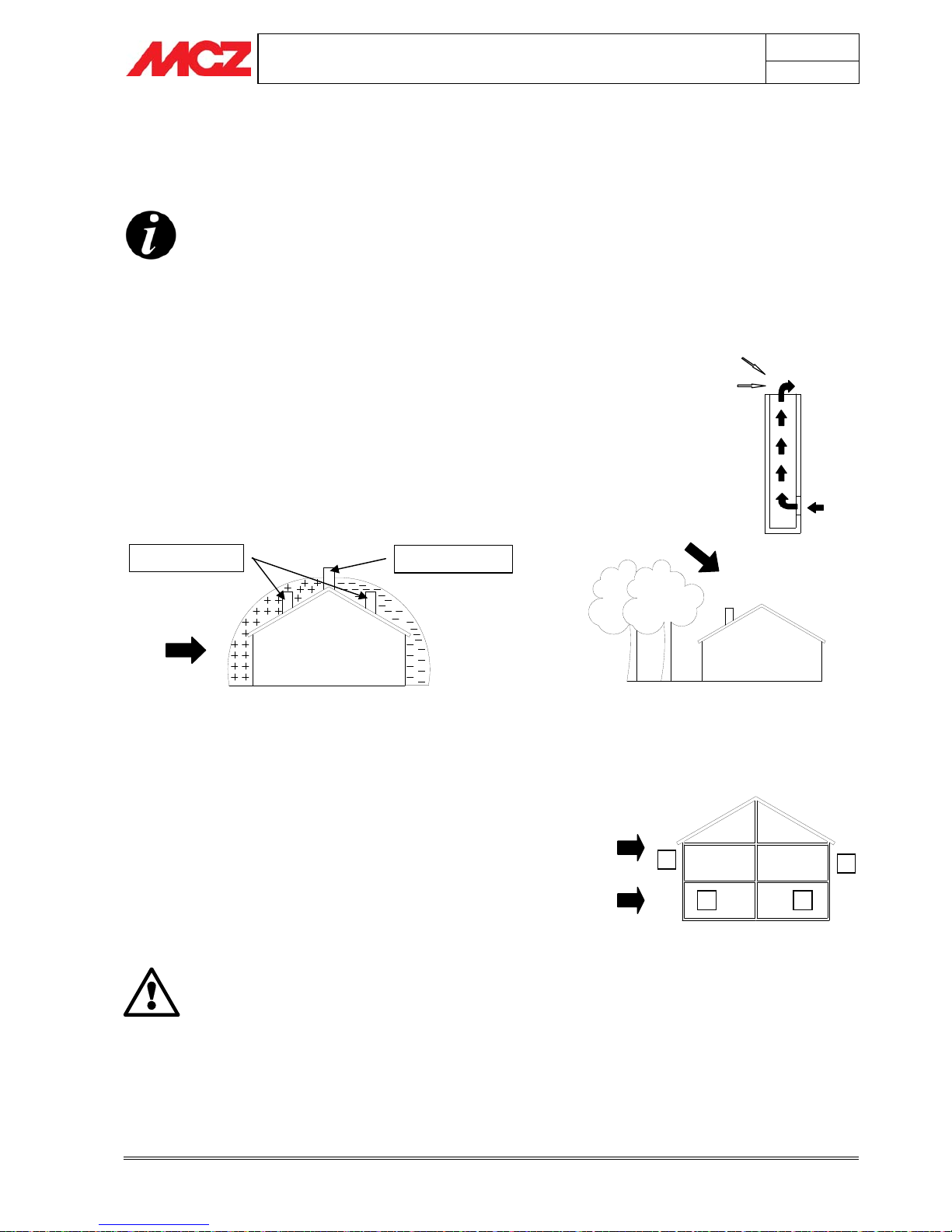
2.9. OPERATING PROBLEMS CAUSED BY DRAUGHT
DEFECTS IN THE FLUE
Of all the weather and geographical conditions which affect the
operation of a flue pipe (rain, fog, snow, altitude a.s.l., exposure to
sunlight, direction of facing), the wind is unquestionably the most
decisive. In fact, along with thermal depression caused by the
difference in temperature inside and outside of the chimney, there is
another type of depression or over-pressure: dynamic pressure caused
by the wind. An updraft always increases depression and hence
draught. A crosswind increases depression provided the cowl has been
installed properly. A downdraft always decreases depression, at times
inverting it.
Besides the direction and force of the wind, the position of the flue and
the cowl with respect to the roof of the building and the surrounding
landscape is important.
The wind also influences the operation of the chimney indirectly by
creating high-pressure and low-pressure zones, not only outside the
building but inside as well. In rooms directly exposed to the wind (2),
an indoor high-pressure area can be created which can augment the
draught in stoves and fireplaces, but it can be counteracted by the
external high pressure if the cowl is situated on the side exposed to the
wind (1). On the other hand, in the rooms on the opposite side from
the direction of the wind (3), a dynamic depression can be created
which competes with the natural thermal depression developed by the
chimney, but this can be compensated for (sometimes) by locating the
flue on the opposite side from the direction of the wind (4).
IMPORTANT!
The operation of the pellet stove is noticeabl
y
sensitive to the conformation and position of the flue
which is adopted.
Hazardous conditions can only be overcome by
suitable setting-up of the stove carried out by
qualified MCZ personnel.
1
2 3
4
E.g. Crosswind 2: 8 m/sec:
Depression of 30Pa
E.g. Downdraft at 45° of 8m/sec.
Overpressure of 17 Pa
1-2 = High-pressure zones
3-4 = Low-pressure zones
WIND
Least favourable points
Most favourable position
WIND
Downdraft
High-pressure
Low-pressure zone
PELLET STOVES Chapter 2
INSTALLATION AND USE MANUAL
page
18
Theoretical notions for installation Technical service - Rights reserved MCZ S.p.A. - Reproduction prohibited
2.10. PLUMBING CONNECTION
IMPORTANT!
The connection of the stove to the plumbing system
must be carried out ONLY
by specialized personnel
who are capable of carrying out installation properly,
in compliance with current standards in the country
of installation.
If installation of the stove will involve interaction
with another, pre-existing system complete with
heating equipment (gas boiler, methane boiler, fuel
oil boiler, etc.), it is even more advisable to call in
qualified personnel, who subsequently will be
responsible for conformity of the system with current
applicable law.
MCZ will not be held responsible for damage to
persons or things in the event of failed or incorrect
operation if the aforementioned warnings are not
complied with.
For connection of the plumbing system to the stove, the user should
refer to chapter 3, INSTALLATION AND ASSEMBLY; specifically,
paragraph 3.4, CONNECTION TO PLUMBING SYSTEM
PELLET STOVES Chapter 3
INSTALLATION AND USE MANUAL
page
19
Installation and assembly Technical service - Rights reserved MCZ S.p.A. - Reproduction prohibited
3. INSTALLATION AND ASSEMBLY
3.1. DRAWINGS and TECHNICAL CHARACTERISTICS
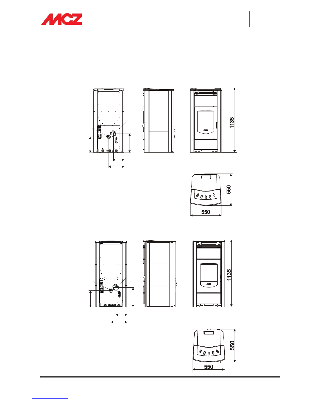
3.1.1. Dimensions of POLAR-NOVA in HYDRO version with no kit for the
production of domestic hot water
192
275
334
281
Ø80
Ø48
3.1.2. Dimensions of POLAR-NOVA in HYDRO version with kit for the production
of domestic hot water
192
275
334
281
Ø80
Ø48
PELLET STOVES Chapter 3
INSTALLATION AND USE MANUAL
page
20
Installation and assembly Technical service - Rights reserved MCZ S.p.A. - Reproduction prohibited
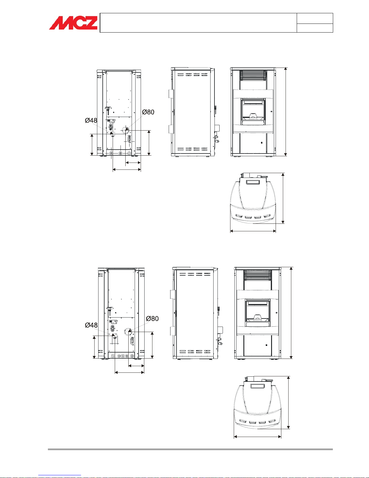
1120
578
643
198
364
281
330
1120
578
643
198
364
330
281
3.1.3. Dimensions of ATHOS POWER in HYDRO version with no kit for the
production of domestic hot water
3.1.4. Dimensions of ATHOS POWER in HYDRO version with kit for the
production of domestic hot water
 Loading...