

Pellet stoves
Installation and use
manual

Contents
Introduction
Preface
Symbols used
Chapter 1 Information
1.1 Guarantee conditions
1.2 Safety ins tructions
1.3 Operating instructions
1.4 Safety devic es
1.5 Operating principle
1.6 The pellets
1.7 Models of stove VEGA-ASTRA-AURORA-ANTARES
1.8 Technical characteristics
Chapter 2 Installation
2.1 Working environment
2.2 Preparation
2.3 Installation and fitting
2.4 Connection to the external air intake
2.5 Connection to the flue
2.6 Connection to an external fluepipe in insulated or double-walled pipe
2.7 Connection to a chimney or flue duct
2.8 Operating problems caused by draught defects in the flue
2.9 Fitting the ceramic cladding
Page
4
5
6
7
8
9
10
12
13
14
15
15
17
18
18
19
20
Chapter 3 Use of the stove
3.1 Checks to make before lighting the stove
3.2 Loading the pellets
3.3 Instructions and advice on first lighting
3.4 Control panel
3.5 Managing the stove with the LCD remote control
3.6 Settings to carry out before first lighting
3.7 Setting the current time
3.8 Selecting the display language
3.9 Selecting the recipe according to the type of pellet used
3.10 How to display and program the selected recipe
3.11 Manual operation: lighting the stove using the control panel or the remote
3.12 Automatic operation with the digital room thermostat
3.13 Passing from manual operation to automatic
3.14 Passing from automatic operation to manual
3.15 Automatic operation with the timer-thermostat
3.16 Programming the timer-thermostat
3.17 Operation of the stove using the external thermostat
3.18 Connecting the external thermostat
3.19 Watching the flame
3.20 Alarm signals
3.21 Other messages
3.22 Lockout of the stove
3.23 Shutting the stove down
3.24 Locking the keyboard on the control panel and the LCD remote
24
24
25
26
27
28
28
28
27
30
31
32
32
32
33
34
36
36
37
38
39
39
40
40
1

Chapter 4 Maintenance
4.1 Periodical cleaning and checks
4.2 Cleaning the glass
4.3 Monthly check
4.4 Check to be carried out every 2 or 3 months
4.5 Non-scheduled maintenance
4.6 Shutting the stove down (end of season)
4.7 Replacing the batteries in the remote control
4.8 Replacing the fuse in the main switch
4.9 Checking the internal components
4.10 Maintenance summary
41
41
42
42
42
43
43
43
44
44
Chapter 5 Electrical system
5.1 Electrical system 45
5.2 Maintenance and/or replacement of the electronic boards 46
Chapter 6 Useful t i ps in case o f problems dur i n g operation 47
Chapter 7 Accessories for pellet stoves 50
Chapter 8 Spare parts for pellet stoves 51
Chapter 9 Memo for the installer 56
Chapter 10 Summary of main instructions 58
2
Introduction
Preface
Dear Customer,
We would like to thank you for the preference which you have decided to bestow on MCZ
products, and particularly for choosing one of the MCZ Pellet range. We are convinced that as
you use it, you will appreciate the quality of the product, which is the fruit of careful planning and
meticulous testing. Our object is to combine technological complexity with simplicity of use, and,
above all, with safety.
In order to get the best performance from your stove and to enjoy to the full the warmth
and the sense of well-being which the flame will diffuse through the home, we recommend
that you read this booklet carefully before lighting the stove for the first time.
Once you have learnt the basics, you will be able manage to best advantage the various levels of
power and the potential for presetting, and you will also pick up a few little hints about cleaning
and setting.
While thanking you again, may we remind you that the stove MUST NOT be used by children, and
that they must always be kept at a safe distance from it!
Symbols used
Warning and safety notice
This warning sign, used at various points in this booklet, indicates that the message to
which it refers should be carefully read and understood, because failure to comply with
what these notices say can cause serious damage to the stove and put the user's safety
at risk.
Information
This symbol is intended to highlight information important for the proper functioning of the
stove. Failure to comply with what these notices say will compromise the use of the stove
and is likely ro result in unsatisfactory operation.
3
Information

1.1 Guarantee conditions
MCZ guarantees the stove, excluding the components listed below which are subject to normal
wear and tear, for a period of two years from the date of purchase, as proved by a supporting
document which gives the name of the vendor and the date on which the sale took place. The
guarantee is conditional on the guarantee certificate being filled in and returned within 8 days, and
requires that the product be installed and tested by a specialised installer, according to the
detailed instructions given in the instruction booklet supplied with the product.
The term 'guarantee' is to be understood to denote the free-of-charge replacement or repair of
parts recognised to have been defective at the start by reason of manufacturing defects.
Limitations
The above guarantee does not cover components relating to electrical and electronic parts, or
fans, on which the guarantee periood is 1 year from the purchase of the product, documented as
specified above. The guarantee also does not cover parts subject to normal wear and tear:
gaskets, glass, and all the removable parts of the firebox.
The replacement parts will be guaranteed for the remainder of the guarantee period starting from
the date of purchase of the product.
Exclusions
Variations in colour in the painted or ceramic parts, and crackling of the glaze on the ceramics, do
not constitute grounds for a claim under the guarantee, as they are natural characteristics of the
material and of the use of the product.
The guarantee does not cover any parts which may be found to be faulty as a result of negligence
or carelessness in use, or of incorrect maintenance, or of installation not complying with MCZ's
specification (see the relevant chapters in this user manual).
MCZ refuses to accept any responsibility for any damage which may be caused, directly or
indirectly, by persons, animals or things in consequence of the failure to observe all the
prescriptions laid down in the instruction booklet, especially those concerning warnings on the
subject of installation, use and maintenance of the appliance.
In the event of failure of the product, the staff of the technical assistance department will arrange
for its repair in the shortest time possible from the request, always provided that no claim shall
arise from the period in which th product cannot be used.
Damage caused by transport and/or handling is excluded from the guarantee.
For installation and use of the product, reference must be made exclusively to the booklet
supplied.
The guarantee will be invalidated in the event of damage caused by tampering with the appliance,
atmospheric agents, natural disasters, electrical discharges, fire, defects in the electrical system,
and lack of, or incorrect, maintenancein terms of the manufacturer's instructions.
CLAIMS UNDER THE GUARANTEE:
the request for action under the guarantee must be addressed to the retai l er, who will forward the claim to MCZ's technical assistance service.
MCZ refuses to accept any responsibility in the event that the stove or any other accessory
have been improperly used or modified without authorisation.
For all replacement of parts, only original MCZ spare parts must be used.
MCZ DECLARES THAT THE STOVE WHICH YOU HAVE
PURCHASED COMPLIES WITH EEC DIRECTIVE 89/336
and 72/23 and SUCCESSIVE AMENDMENTS
Information
4
1.2 Safety instructions
Installation of the stove, making the electrical connections, checking its operation, and
maintenance are all tasks which should be carried out by qualified and authorised
personnel.
Install the stove in accordance with the regulations in force in your local area, region and
country.
For the correct use of the stove and of the electronic apparatus connected to it, and to prevent
accidents, the instructions given in this booklet must always be followed.
In addition, adjustment and regulation must be carried out by adults. Errors or incorrect settings
can give rise to hazardous conditions and/or bad running.
Before beginning any operation, the user, or whoever is preparing to operate on the stove, must
have read and understood the entire contents of this instruction booklet.
The stove must be used only for the purpose for which it is intended. Any other use must be
considered improper and therefore dangerous.
Do not use the stove for standing on or as any kind of support.
Do not put washing to dry on the stove. Any clotheshorses and suchlike must be kept a suitable
distance from the stove. – Danger of fire.
All responsibilty for improper use is taken entirely by the user and such use relieves MCZ of any
civil or criminal responsibility.
Any kind of tampering or unauthorised substitution of non-original spare parts can be hazardous
for the safety of the operator and relieves MCZ of any civil or criminal responsibility.
Most of the surfaces of the stove are extremely hot (the door, the handle, the glass, smoke
discharge pipes etc.). Avoid coming into contact with these parts, therefore, without adequate
protective clothing or suitable implements, such as gloves with thermal protection or implements
which leave the hands cool.
Carefully explain this hazard to elderly people, disabled people and particularly to all children,
keeping them away from the stove while it is running.
On no account should the stove be run with the door open or the glass broken.
Do not touch the stove with wet hands, in view of the fact that it is an electrical appliance. Always
disconnect the supply cable before doing anything to the unit.
Before carrying out any cleaning or maintenance operation, make sure in advance that the the
stove is disconnected from the mains electricity supply, by turning off the main switch located on
the back of the stove, or by unplugging the supply cable.
The stove must be connected to an electrical system which is equipped with an earth conductor,
as laid down in diectives 73/23 EEC and 93/98 EEC.
The system must be of adequate rated capacity for the stated electrical power of the stove.
Incorrect installation or faulty maintenance (not conforming to the requirements set out in this
booklet) can cause harm to people, animals or property. In such cases MCZ is absolved from any
civil or criminal responsibility.
5
Information

1.3 Operating instructions
In case of any problems, get in touch with your dealer, or a qualified engineer authorised by
MCZ, and if a repair is necessary, insist on the use of original spare parts.
Shut the stove down in the event of a breakdown or bad running.
Use only the fuel specified by MCZ (6 mm diameter pellets. The fuel must be supplied to the stove
only by the automatic feed system.
Pellets must not be fed manually into the burner.
Periodically check and clean the smoke outlet ducts (connection to the flue pipe).
The accumulation of unburnt pellets in the burner after repeated "ignition failures" must be removed before lighting.
Do not wash the inside of the stove with water.
Do not use water for washing the stove. The water could get inside the unit and damage the
electrical insulation and cause electric shocks.
The pellet stove is not a cooking appliance.
Do not expose your own body to hot air for extended periods. Do not overheat the room which
you are occupying, where the stove is installed. This could cause physical damage and also give
rise to health problems.
Do not expose plants or animals directly to a current of hot air. Both plants and animals could be
harmed by it.
Do not put anything in the hopper other than wood pellets.
Always keep the the cover of the fuel hopper closed.
Keep this instruction manual carefully because it must stay with the stove throughout its working
life. If the stove is sold or transferred to another user, always make sure that the booklet goes with
the product.
If it gets lost, ask MCZ or your authorised dealer for another copy.
Instal the stove in a location which is suitable for firefighting, and equipped with all services such
as air and electricity supply and provision for discharging combustion gases.
If the stove and the ceramic cladding are in storage, it should be in a place that is free of damp,
and they should not be exposed to extremes of temperature.
It is inadvisable to base the stove directly on the floor, and if the floor is made of flammable
material, it must be suitably insulated.
Do not light the stove with flammable materials if the ignition system breaks down.
Information
6
1.4 Safety devices
The stove is fitted with the following safety devices:
PRESSURE SWITCH
Monitors pressure in the smoke duct. It is designed to shut down the pellet feed screw in the
event of an obstructed flue or significant back-pressure (from the wind).
SMOKE TEMPERATURE SENSOR
Monitors the temperature of the smoke, and gives permission for startup or shuts the stove down
when the smoke temperature falls below the preset value.
FUEL HOPPER TEMPERATURE SENSOR.
If the temperature exceeds the preset safety level, it immediately shuts down the running of the
stove, and has to be reset manually before the stove will restart. Take care when carrying out the
operation of resetting it, because if the stove locks out a second time, it will be necessary to call
the technical assistance centre.
ELECTRICAL SAFETY
The stove is protected against violent surges of current by the main fuse, which is located on the
control panel at the rear of the stove. Other fuses to protect the electronic boards (main board and
heat-exchanger board) are to be found on the boards themselves.
FAILURE OF THE SMOKE EXTRACTION FAN
If the fan stops, the electronic board shuts off the supply of pellets in good time, and an alarm
message is displayed.
BREAKDOWN OF THE REDUCTION MOTOR
If the reduction motor stops, the stove continues to function until it has cooled down to the
minimum level.
TEMPORARY POWER OUTAGE
After a brief interruption of the electrical power, the stove relights automatically.
FAILURE TO LIGHT
If during the lighting stagea flame does not start, the stove automatically makes a further attempt
to light.
TAMPERING WITH THE SAFETY DEVICES IS PROHIBITED
It is only after eliminating the cause which gave rise to the intervention of the safety system,
that it is possible to relight the stove and thus reset the automatic operation of the sensor.
Attention !
If the stove is not used as described in this instructi on booklet, the ma nufacturer refu ses to
accept any responsibility for damage to pers ons and prop erty that may arise. The ma nufacturer
furthermore refuses to accept responsibility for damage to persons and property arising from
the failure to observe all the rules contained in the manual and in particul ar:
• Failure when carrying out works of maintenance, cleaning and repair to adopt all
necessary measures and precautions.
• Tampering with the safety devices.
• Removing the safety devices.
• Failure to connect the stove to an efficient system for the discharge of smoke.
• Failure to check in advance that the room where the stove is to be installed is
adequately ventilated.
7
Information
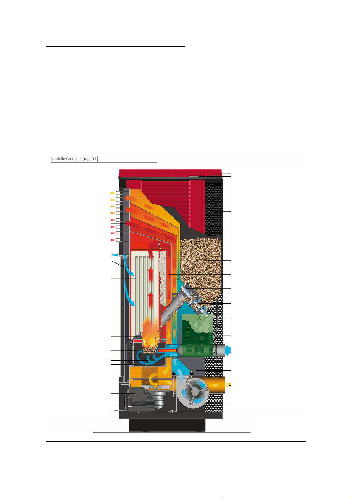
1.5 Operating principle
The pellets are picked up from the hopper on board the stove and transported by a feed screw.
They are then introduced into the combustion chamber and fall directly into the stainless steel
grate.
The quantity of pellets introduced into the grate and the corresponding air of combustion are
predetermined, programmed and controlled by an electronic board.
In the lighting phase, the electronic board activates the smoke extraction fan and the ceramic
sparkplug, which heats up and causes the fuel to ignite at a temperature of about 200°C. After
about 20 minutes, the lighting phase is complete, and the control unit puts the stove into operating
mode.
In this phase, on the basis of the instructions which we provide via the infrared remote (5 power
levels), the electronic board regulates the exact relationship between quantity of fuel, combustion
air and convection air, and provides continuous monitoring of all the components connected to it,
indicating if necessary the presence of any operating problems and stopping the process.
16 Ceramic cladding
1 Door for loading pellets
2 Pellet compartment sensor
3 Outlet for convection warm air
4 Outlet for forced warm air
5 Deflector grille
6 Air for cleaning glass
7 Combustion chamber in Alutec
8 Door with glass (750° C)
9 Grate in stainless steel
10 Secondary combustion air
11 Primary combustion air
12 Central ash drawer
13 Side ash drawer
14 Smoke extractor
15 Door opening handle
17 Control panel
18 Rear closing panel
19 Pellet hopper
20 Heat exchange chamber
21 Pellet feeder
22 Pellet feed Archimedes screw
23 Pellet conduit
24 Electronic control board
25 Combustion air intake Ø 50
26 Smoke sensor
27 Smoke outlet Ø 80
28 Warm air fan
Information
Cross-section of
Antares stove
8
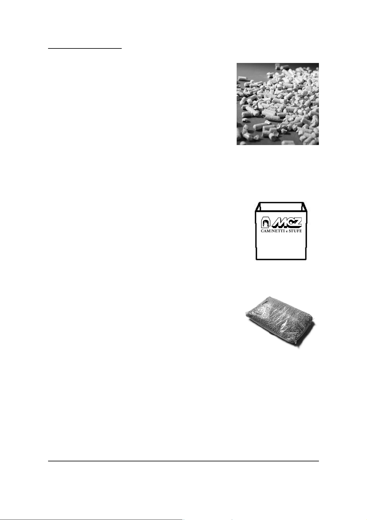
1.6 The pellets
Wood pellets are manufactured by hot-extruding compressed
sawdust which is produced during the working of natural dried
wood. The compactness of the material comes from the lignin
which is contained in the wood itself, and allows the production
of pellets without the use of glues or binders.
The market offers different types of pellet with characteristics
which vary depending on what mixture of woods is used. The
diameter varies between 6 mm and 8 mm, with a standard length
in the range 5 mm to 30 mm. Good quality pellets have a density
which varies between 550 kg/m
content which varies from 5% tp 8% by weight.
With the aim of guaranteeing the stated rate of fuel consumption per hour and ensuring
optimum combustion, MCZ has devised a patented method which allows the identification
and cataloguing of any type of pellet with a 6 mm diameter, in terms of its specific gravity
and particle size.
By using the special measuring container and following the procedure
set out in the paragraph on lighting the stove, the user can determine
the correct settings for configuring the stove.
Besides being an ecological fuel (exploiting timber residues to the
maximum and achieving cleaner combustion than is possible with
fossil fuels), pellets also have technical advantages. While goodquality timber has a calorific power of 4.4 kW/kg (with 15% moisture,
therefore after about 18 months' seasoning), the equivalent figure for
pellets is 5.3 kW/kg.
To ensure good combustion, the pellets must be stored in an area that
is free of damp, and protected from dirt. Pellets are supplied in 15 kg
bags, so they are very convenient to store.
Good quality pellets ensure good combustion, thus lowering the
emission of harmful agents into the atmosphere.
The poorer the quality of the fuel, the more frequently will
intervention be necessary for cleaning the internal parts, such as
the grate and the combustion chamber.
The pellets must be produced from pure wood which has not been
treated chemically.
The standards DIN 51731 and ONORM M 7135 certify a high-quality
pellet with the following characteristics:
Calorific power: 5.3 kW/kg
Density: 700 kg/m
3
Moisture content: 8% max by weight
Ash percentage: 1% max by weight
Diameter: 6-6.5 mm
Length: 30 mm max
Content: 100% untreated wood, with no added bonding substances (bark percentage 5% max)
Packaging: in bags made from ecologically compatible or biodegradable material
MCZ emphatically recommends using certified fuel in its stoves.
The use of fuel of inferior quality or not conforming to the specification given above
compromises the running of your stove and can therefore lead to the termination of the
guarantee and of the manufacturer's responsibility for the product.
Vega, Astra,Aurora and Antares stoves run exclusively on pellets with a diameter of 6 mm
and a length rage from 5 mm to a maximum 30 mm.
3
and 700 kg/m3, with a moisture
Pellet measuring
container
15 kg bags of pellets
9
Information
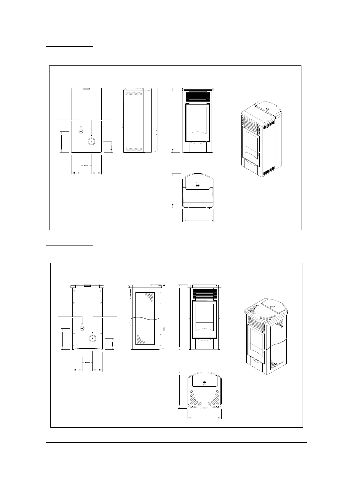
1.7 Vega
d.50 d.80
1000
325
162
154 154
Astra
d.50 d.80
172
530
470
1010
325
162
154
154
Technical characteristics
172
570
520
10
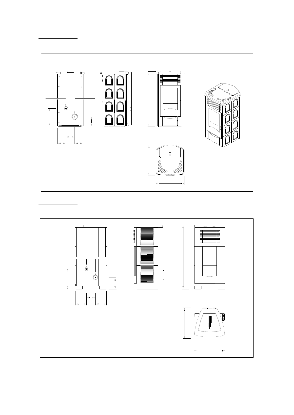
Aurora
d.50
325
162
154
Antares
d.80
1010 570
172
154
520
11
d.50 d.80
366
162
204 204
1160
214
540
570
Technical characteristics
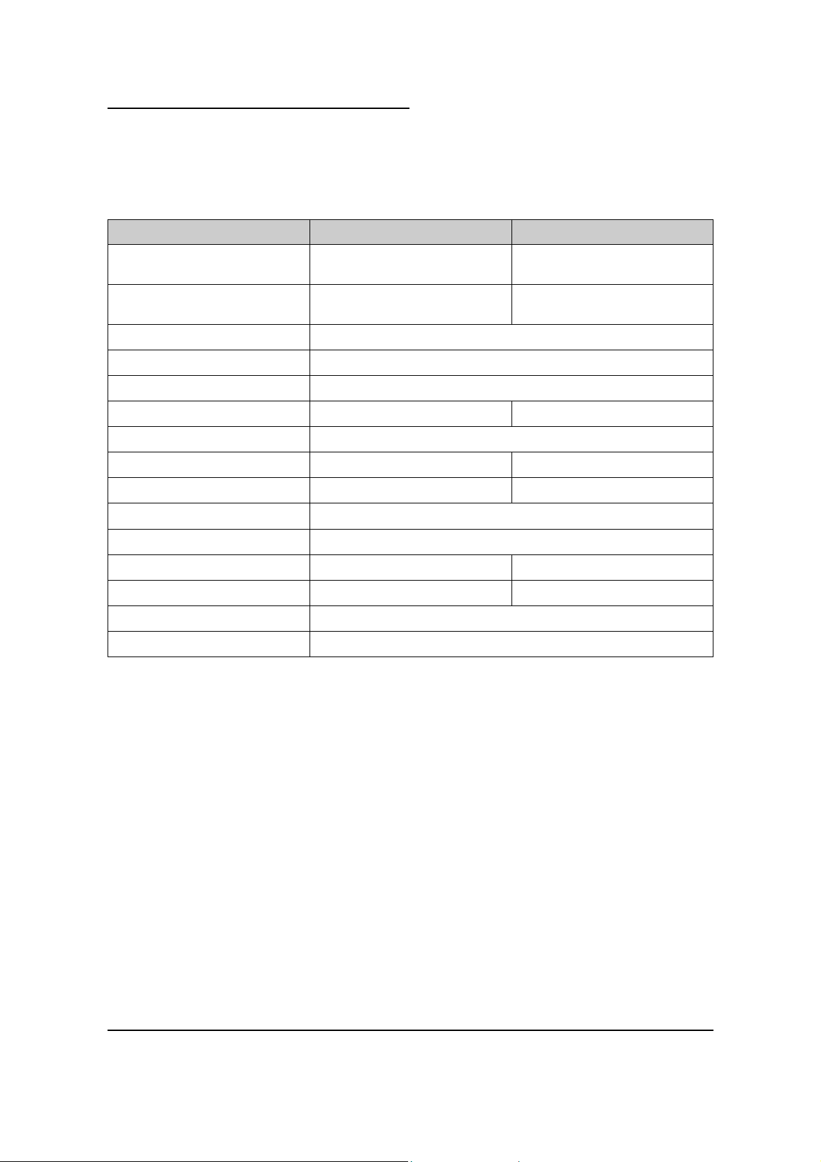
1.8 Technical characteristics
Technical characteristics Vega - Astra - Aurora Antares
Overall thermal power
ITALY
Overall thermal power
DIN
Efficiency
Smoke temperature 120 / 215 °C
Minimum draught
Hopper capacity 23 litres 43 litres
Fuel pellet type Pellet diameter 6 mm. Length range 5-30 mm
Pellet consumption per hour Min 0.6 KG/h Max. 2 KG/h Min 0.7 KG/h Max. 2.2 KG/h
Runtime between feeds Min 27 h Max. 8 h Min 48 h Max. 16 h
Combustion air inlet External diameter 50 mm.
Smoke outlet External diameter 80 mm.
Nett weight 100 Kg. 145 Kg.
Weight with packaging 120 Kg. 170 Kg.
Installed electric power 130 W run. 380 W startup.
Supply voltage 230 V 50 Hz.
8.5 KW / 7310 kcal 9.9KW / 8500 kcal
2,5 KW / 2150 kcal 2.9 KW / 2500 kcal
78 / 81 %
0.1 mbar—10 Pa
Technical characteristics
12
2.1 Working environment
For proper functioning and a good temperature distribution, the stove should be positioned in a location where
it is able to take in the air necessary for combustion of the pellets (about 40 m
down in the standard governing the installation (UNI - CIG 7129, 7131 and subsequent updates).
The volume of the room must not be less than 30 m
The air must come in through permanent openings made in walls (in proximity to the stove) which give onto
the outside, with a minimum cross-section area of 100 cm
3
.
2
.
3
/h must be available) ,as laid
These openings must be made in such a way that it is not possible for them to be obstructed in any way.
Alternatively, the air may be drawn from rooms next door to the room which needs ventilation, provided that
these rooms have an air intake from outdoors and are not used as bedrooms or bathrooms and provided
there is no fire risk such as there is for example in garages, woodsheds, and storerooms. The provisions of
standards UNI 7129 and 7131 and subsequent amendments absolutely must be respected.
It is not permissible to install the stove in bedrooms, bathrooms or showers, or in
a room where another heating appliance is installed (fireplace, stove etc.) which
does not have its own independent air intake.
Locating the stove in a room with an explosive atmosphere is prohibited.
The floor of the room where the stove is to be installed must be strong enough to take its
weight.
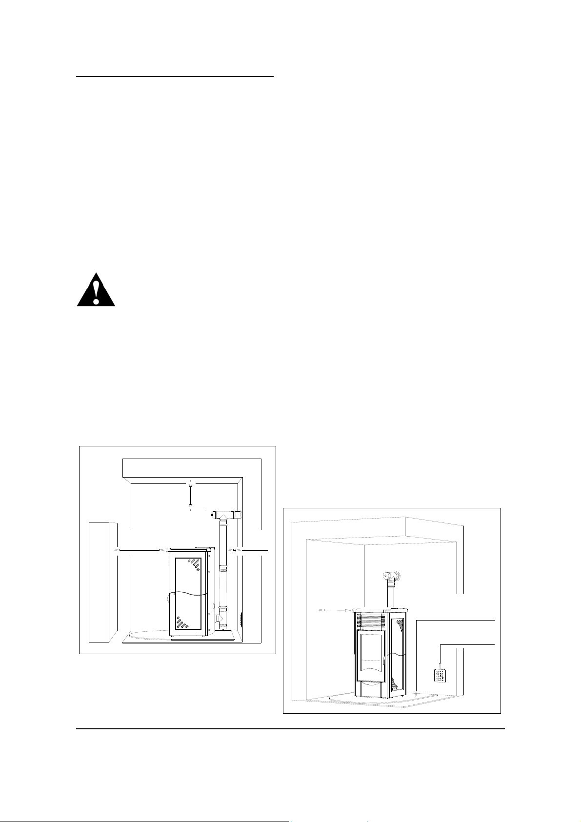
If the walls are not flammable, position the stove with a clearance to the rear of at least 10 cm.
In the case of walls made of flammable material, maintain a minimum clearance to the rear of 20
cm, a clearance to the sides of 50 cm, and a clearance to the front of 150 cm. If the room
contains objects which are believed to be particularly delicate, such as hangings, sofas and other
furniture, their distance from the stove should be considerably increased.
If the floor is made of wood, fit the floor protection plate.
20 cm
150 cm
20 cm
Clearance distances between the stove and
flammable walls (all measurements to be taken
from the outside surface of the appliance).
13
50 cm
Floor protection plate
Min.100 cm²
Installation
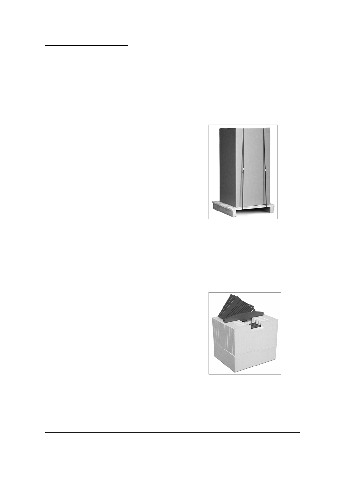
2.2 Preparation
The Vega stove is delivered in a single package.
Astra, Aurora, and Antares stoves are delivered in two
packages:
The first contains the stove unit Fig.1
The second contains the ceramic cladding.Fig.2
Open the packaging, take off the bands, remove the
stove unit from the pallet and position it in the chosen
location, taking care that its position complies with the
above instructions.
The main stove unit must always be moved in an
upright position and a trolley must always be used.
Take particular care to see that the door and its glass
are protected from mechanical impact which could
damage them.
Moving the product must always be done with care.
If possible, unpack the stove in the area where it is
going to be installed.
The materials which make up the packaging are not
toxic or harmful, so no special procedures for disposal
by required.
Their storage, disposal or possible recycling are
therefore the responsibility of the final user, in
compliance with current legislation on the subject.
Do not store the stove unit or its cladding without their
packaging.
Fig.1
Installation
Fig.2
14
2.3 Installation and fitting
Installation and assembly of the stove must be carried out by a qualified engineer.
The stove must be installed in a suitable position to allow the normal operations of opening and
ordinary maintenance.
The site must be:
• capable of providing the environmental conditions for operation
• provided with a suitable electricity supply: 230-240 V 50 Hz (EN73-23)
• capable of taking an adequate system for smoke discharge
• provided with external ventilation
• provided with an earth connection complying with CEI 64-8
The stove must be connected to a flue pipe or an internal or external vertical conduit
conforming to the standards UNI 7129 - 7131 – 9615.
The stove must be positioned in such a way that the electrical plug is accessible.
IMPORTANT !
The stove must be connected to a flue pipe or a vertical conduit which can
discharge the fumes at the highest point of the building.
The fumes are however derived from the combustion of wood products, and if
they come into contact with or close to walls, they can make dirty marks.
Also take care because the fumes are very hot but almost invisible, and can cause burns
on contact.
The holes for the passage of the smoke pipe and for the intake of air from outside should
be made before positioning the stove unit.
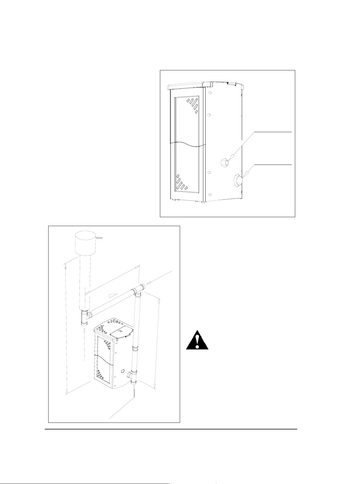
2.4 Connection to the external air intake
It is essential that at least as much air must be able to flow into the room where the stove is
installed as is required for proper combustion in the appliance and for the ventilation of the room.
This can be effected by means of permanent openings in the walls of the room to be ventilated,
which give onto the outside, or by single or collective ventilation conduits.
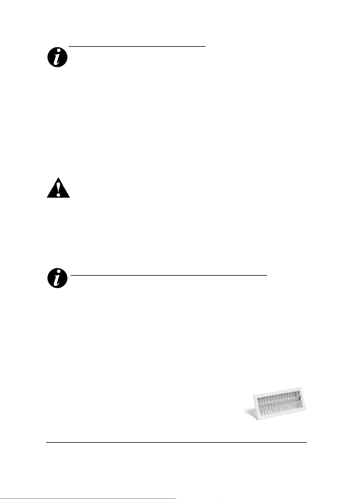
For this purpose, make a hole right through an external wall in proximity to the stove, with a
minimum free section of 100 cm² (equivalent to a round hole of 12 cm diameter or a square hole
10x10 cm), protected by a grille on the inside and the outside.
The air intake must:
• communicate directly with the room where the stove is installed
• be protected by a grille, metal mesh or suitable guard, as long as this does not reduce the
area below the minimum.
• be positioned in such a way as to be impossible to
obstruct
It is not compulsory to connect the air intake directly with the
stove (so that it draws air directly from outside), but it is essential
at all events to ensure an airflow of 50 cubic metres per hour by
the use of a hole of the dimensions given.
See standard UNI 10683 REV.
15
Grille for external air intake
Installation
When making the hole for the passage of
the smoke discharge pipe, it is necessary
to take into account the possible
presence of flammable materials. If the
hole will be going through a wall made of
wood or any other material which is
sensitive to heat, the INSTALLER MUST
first of all use the special wall union
(diam.13cm minimum) and properly
insulate the pipe of the stove that passes
through it, using adequate insulation
materials (thickness1.3—5cm with
minimum thermal conductivity of 0.07 W/
m°K).
The same is true if the stove pipe must
run through vertical or horizontal
stretches passing in proximity (min.20cm)
to the heat-sensitive wall
As an alternative we recommend the use
of insulated pipe, which can also be used
on the outside to avoid condensation.
Combustion air
intake ø 50
Smoke
outlet ø 80
Inspection
Height greater than 4 metres
cover
Smoke duct
m
u
m
i
x
a
M
t
n
e
i
d
a
r
G
o
i
t
c
e
p
s
r
n
e
I
v
o
c
Pipes and unions with suitable gaskets
s
e
r
t
e
m
3
-
2
%
5
-
3
n
I
n
o
i
t
c
e
p
s
r
e
v
o
c
must always be used, to guarantee a
hermetic seal.
All sections of the smoke duct must be
inspectable and removable to enable
periodic internal cleaning. Tee connectors
with inspection caps should be used.
Position the stove bearing in mind all the
instructions and considerations above.
Important
All 90 degree changes of direction in
the flue pipe must be fitted with
suitable tee connectors to allow the
n
i
M
u
m
i
1
m
s
e
r
t
e
m
2
5
.
possibility of inspection (see the pellet
stove accessory list).
n
It is absolutely unacceptable to fit a
grille on the end of the discharge pipe,
because it could lead to poor running
of the stove.
Installation
16
Lining up the
smoke outlet and
the connecting
pipe
Fig.3 Fig.4
If the stove needs to be connected to a discharge pipe which goes through the rear wall (to
connect up with the flue), take the greatest care to make sure that the joint is not stressed. Use
the four adjustable feet (Fig. 3) to get the stove correctly levelled so that the smoke outlet is lined
up with the connecting pipe. If the smoke outlet of the stove is forced or used improperly to
lift it or position it, the operation of the stove can be damaged irreparably. (Fig. 4)
Some typical examples of correct installation are illustrated below.
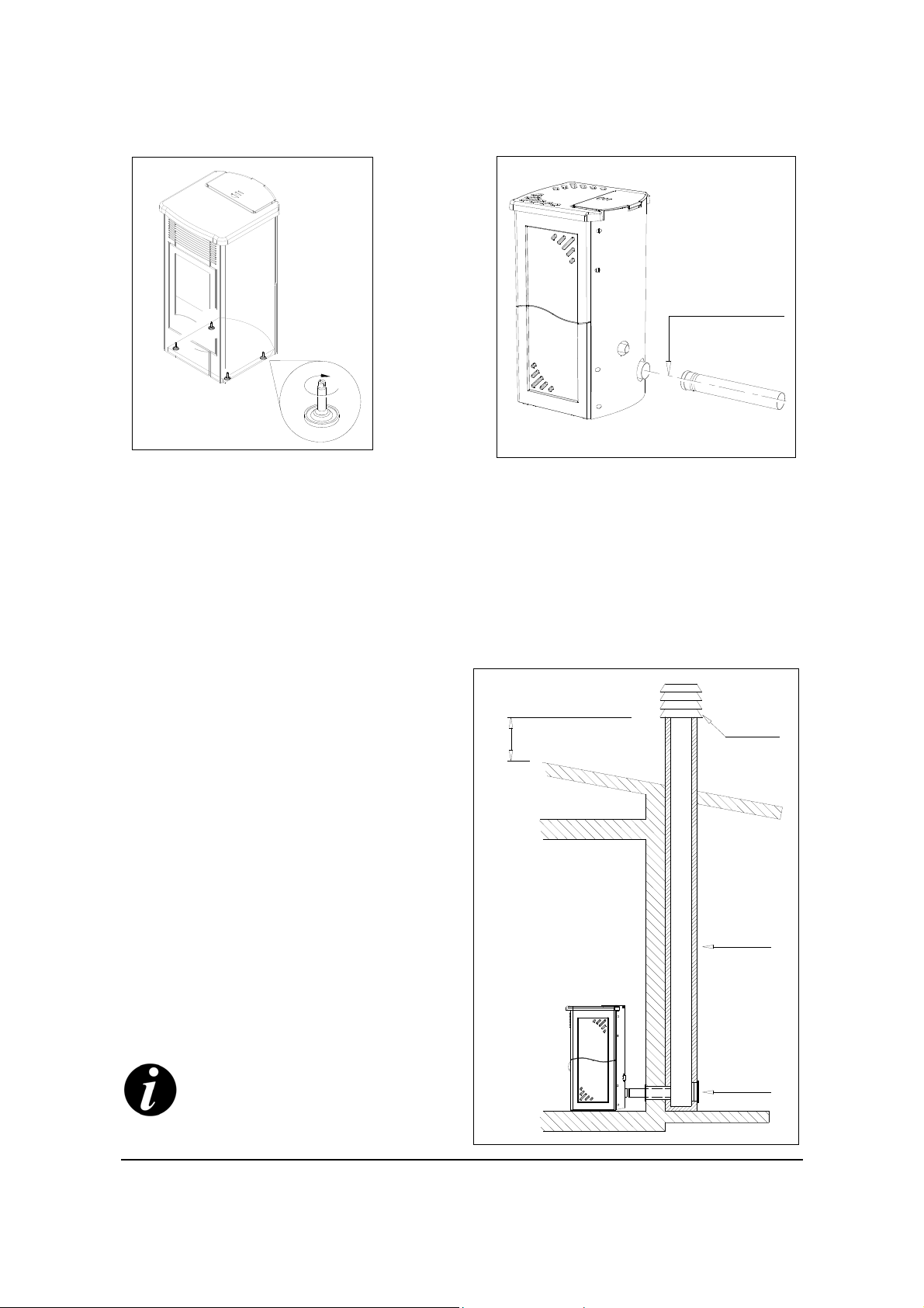
2.5 Connection to the flue
The flue of must have internal dimensions not
larger than 20x20 cm or diameter 20 cm. In the
case of a flue with larger dimensions or in poor
condition (e.g. cracks, poor insulation etc.), it is
advisable to line the flue with a stainless steel
pipe of suitable diameter for its entire length,
right up to the top (Fig 5).
Check with suitable instruments that there is a
minimum draught of 12 Pa.
At the bottom of the flue pipe, provide an
inspection cap to allow periodic checking and
cleaning, which must be done annually.
Make a gas-tight connection to the flue pipe,
using pipes and connectors as recommended
by us.
It is imperative that a windproof cowl should be
fitted which complies with the standards in
force (UNI 7129 - 7130 - 9615).
This type of connection ensures the
evacuation of the fumes even in the
event of a temporary power cut.
Fig.5
50 cm
Windproof
cowl
Flue
Inspection
cover
17
Installation
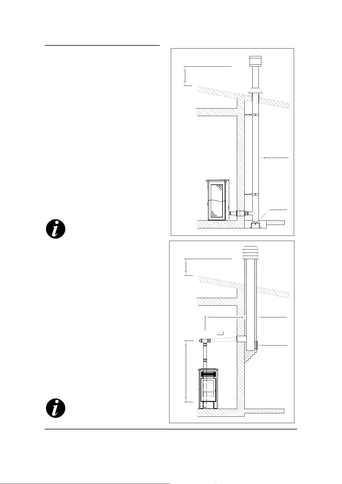
2.6 Connection to an
external fluepipe in insulated
or double-walled pipe
The external fluepipe must have internal dimensions
of minimum 10x10 cm or 10 cm diameter, and
maximum 20x20 cm or 20 cm diameter.
Check with suitable instruments that there is a
minimum draught of 12 Pa. (Fig. 6)
The only type of pipe which is permissible is
insulated (double-walled) stainless steel, smooth on
the inside, fixed to the wall. Flexible stainless steel
pipe must not be used.
At the bottom of the flue pipe, provide an inspection
cap to allow periodic checking and cleaning, whi ch
must be done annually.
Make a gas-tight connection to the flue pipe, using
pipes and connectors as recommended by us.
It is imperative that a windproof cowl should be fitted
which complies with the standards in force (UNI
7129 - 7130 - 9615).
This type of connection ensures the
evacuation of the fumes even in the
event of a temporary power cut.
50 cm
Fig.6
Insulated
external
pipe
Inspection
cover
2.7 Connection to a
chimney or flue duct
For proper functioning, the connecting pipe between
the stove and the chimney or flue duct must have a
slope of not less than 3%. The length of the
horizontal stretch must not exceed 2/3 metres, and
the vertical distance between one tee connector
and another (change of direction) must not be less
than 1.5m.
Check with suitable instruments that there is a
minimum draught of 12 Pa. (Fig. 7)
At the bottom of the flue pipe, provide an inspection
cap to allow periodic checking and cleaning,
which must be done annually.
Make a gas-tight connection to the flue pipe, using
pipes and connectors as recommended by us.
It is imperative that a windproof cowl should be fitted
which complies with the standards in force (UNI
7129 - 7130 - 9615).
This type of connection ensures the
evacuation of the fumes even in the
event of a temporary power cut.
50 cm
Max 2-3 metres
Gradient
3-5%
Min 1.5-2 metres
Flue pipe
Inspection
cover
Fig.7
Installation
18

2.8 Operating problems caused by draught defects in the
flue
Example 1: 8 m/sec wind blowing
downwards at 45°
Example 2: 8 m/sec wind
blowing horizontally
Depression of 30Pa
Least favourable points
Wind
Among all the meteorogical and geographical factors
which influence the operation of a flue (rain, fog, snow,
altitude above sea level, amount of sunlight, exposure to
different compass directions), the wind is certainly the one
which has most effect. Besides the thermal depression
brought about by the difference in temperature between
the inside and outside of the flue, there exists another kind
of depression (and overpressure): the dynamic pressure
induced by the wind. A rising wind always has the effect of
increasing the depression and therefore the draught. A
horizontal wind increases the depression if the cowl is
correctly installed. A descending wind always has the
effect of reducing the depression and sometimes of
reversing it.
Most favourable position
Trees/hills/other buildings
Descending wind
High-pressure zone Low-pressure zone
Besides the direction and force of the wind, the position of the flue and the cowl with respect to
the roof of the building and the surrounding landscape is important. The wind also influences the
operation of the chimney indirectly by creating high-pressure and low-pressure zones, not only
outside the building but inside as well. In rooms directly exposed to the wind (2), an indoor highpressure area can be created which can augment the draught in stoves and fireplaces, but it can
be counteracted by the external high pressure if the cowl is situated on the side exposed to the
wind (1). On the other hand, in the rooms on the opposite side from the direction of the wind (3), a
dynamic depression can be created which competes with the natural thermal depression
developed by the chimney, but this can be compensated for (sometimes) by locating the flue on
the opposite side from the direction of the wind (4)
1-2 High-pressure zones
3-4 Low-pressure zones
Wind
1
The operation of the pellet stove is noticeably
sensitive to the conformation and position of
4
the flue which is adopted.
2 3
Hazardous conditions can only be overcome
by suitable setting-up of the stove carried out
by qualified MCZ personnel.
19
Installation

2.9 Fitting the ceramic cladding on
Astra-Aurora-Antares
ORIENTATION OF THE CERAMICS
After positioning the stove in the chosen location, level up the stove body by means of the
adjustable feet fitted to the base. Carry on with fitting the ceramic cladding only after making the
connection to the flue pipe or the vertical smoke duct as described above.
The ANTARES stove has panels of identical design which can be fitted on the right-hand or the lefthand side, and either way up.
The AURORA stove, however, has panels of identical design which must go in fixed positions (fig. 8).
The ASTRA stove has panels (with different designs) with different layouts for the two sides (fig. 9).
HANDLE THE
5°
CERAMIC PANELS
WITH GREAT CARE
2°
1°
Fig. 8 Aurora stove
Recommended fitting sequence:
• Left-hand side
• Right-hand side
• Top
4°
3°
A T ALL TIMES
2°
1°
5°
4°
3°
Installation
Fig. 9 Astra stove
20

FITTING THE CERAMIC CLADDING
After reading the previous paragraph entitled "Orientation of the ceramics", scrupulously follow the
stages described below.
Take a panel from the pack (following the fitting sequence recommended on the previous page)
and move it to the side of the stove where it is to be fitted (fig. 10 ). Locate the panel so that the
fixed retaining hooks (A) at the front of the stove engage in the rebate in the panel as indicated in
fig. 11.
At the rear of the panel, engage the moveable hooks (B) in the appropriate rebate in the panel.
Using a screwdriver, tighten the screws in the hooks, but not all the way, so as to lock the panel
(fig 12). Check that the panel is secure and aligned with the other panels, bearing in mind that
THE PANELS MUST NEVER BE RIGIDLY FIXED.
Fit the top by resting it on the 4 rubbers (K) fitted to the frame.
K
K
B
A
Fig. 11 Procedure
for ASTRAAURORA-
Fig. 12
21
Fig. 10
Installation

K
Installation of steatite cladding
Support
K
Support
Screws
Screws
Steatite
plate
Always start laying the plates starting from the lower ones.
Orienting it as shown in the diagram below, insert a plate so that the 4 screws attached to it will be
located in the housings of the supports fastened to the stove.
Repeat this operation for the remaining plates and complete by resting the top on the four rubbers
(K) of the structure.
Straight end
Orient the diagram as shown in
the diagram alongside.
The curved joint between the
plates is in the centreline of the
side.
The lower and upper ends are
Curved joint
straight.
Installation
Straight end
22

VARIATION FOR ANTARES
Remove the two screws from the pellet compartment cover, take it off and position the ceramic
top (fig. 13).
Refit the cover and tighten it finally (fig. 14).
Fig. 13
HANDLE THE
CERAMIC PANELS
WITH GREAT CARE
A T ALL TIMES
Electrical connection
Connect the supply cable first at the rear of
the stove and then to an electrical outlet on
the wall. Fig.15
The main switch located on the rear of the
stove should be switched on only when you
want to light the stove. If you do not intend
to use the stove, it is advisable to keep it
switched off.
If the stove is going to be out of use for a
considerable period, it is advisable to
remove the connecting cable from the
Fig. 14
Fig. 15
Installation
23

3.1
Checks to make before lighting the stove
Check that all the safety conditions described
above have been met.
Make sure you have read and completely
understood the contents of this instruction booklet.
Remove from the pellet hopper the cardboard box
containing the general instructions, and any
materials which could burn (various instructions
and stickers).
Check that the central ash-drawer (A) on the Astra-
Vega-Aurora, or the two ash-drawers on the
Antares, is/are correctly positioned and properly
closed.
Check that the grate (B) and its flame shield are
correctly positioned.
Check that the perforated upper deflector (C),
inside the combustion chamber, is positioned
correctly (fig. 16).
After long periods of disuse, remove from the
hopper (using a vacuum cleaner with an
extension) any remains of pellets which
have lain there for some time, since they may
have absorbed moisture, which changes their
original characteristics and makes them
unsuitable for burning.
Check that the electrical connection is correct
(230 V 50 Hz), and turn on the main switch
located on the rear panel of the stove.
Check that on the control panel the display is
lit up with the alternating message OFF /
CURRENT TIME.
C B
Fig.16
A A A
3.2 Loading the pellets
The pellets are loaded through the top of the
stove, by opening the cover. Pour the pellets
into the hopper, up to a maximum of 34 kg
(more than two bags). ( 2 bags for the
Antares and about 23 kg, which is well over 1
bag, for the Vega-Astra-Aurora). See fig. 17.
Do not remove the protective grille from
inside the hopper. When loading pellets,
avoid the bag coming into contact with
hot surfaces.
24
Fig.17
Use of the stove

3.3 Instructions and advice on first lighting
Avoid touching the stove during the initial lighting, since the paint is hardening at this stage.
Touching the paint could make the steel surface show through.
If necessary, touch up the paint with the aerosol spray in the original colour (see the section
"Accessories for pellet stoves").
It is good practice to provide plenty of ventilation during the initial lighting, as the stove will give off
fumes and smell of paint.
Do not remain close to the stove, and, once again, ventilate the room well. The fumes and the
smell of paint will disappear after about an hour of operation, but remember that they are not
harmful to health.
The stove will be subject to expansion and contraction during the stages of lighting and cooling
down, and may therefore make slight creaking noises. This phenomenon is absolutely normal, the
structure being made of sheet steel, and must not be considered a fault.
It is extremely important to be sure not to take the stove to full heat straight away, but to bring it
gradually up to temperature as if it were a car.
If in 'Manual' mode, use the lower heating levels (1st, 2nd, 3rd). On subsequent lightings, you will
be able to enjoy the full heating power available (including 4th and 5th levels), but remember not
to keep the stove running on full power for more than 60-90 minutes. In this way you will avoid
damage to the ceramic panels, the welds and the steel structure.
The first time the stove is lit, leave it in 'Manual' mode and
use only moderate power settings, such as 'Manual 1',
'Manual 2' and 'Manual 3'.
Do not demand full heating performance straight away!
Try to become familiar with the commands transmitted by the control panel and the LCD remote
control. Try to memorise visually the messages which the stove is sending you via its remote
displays (on the control panel and the remote control).
'Manual 1', 'Manual 2' and 'Manual 3' are captions which appear only on the LCD remote control.
Use of the stove
25

3.4 Control panel
Let us get to know the functions of the control panel.
The control panel replicates perfectly the functions of the LCD remote control.
In the tutorial which follows, we examine the control panel in particular, because its display only
partially shows the messages addressed to the user.
8
7
2
1
6
9
3
4
10
Transmitter and receiver
8
3
2
1
4
5
5
KEY 1= Scroll down through menu / decrease set temperature
KEY 2= Increase set temperature / programming functions
KEY 3= Increase stove power level / programming functions
KEY 4= Decrease stove power level / Scroll down through menu
KEY 5= Stove lighting / shutdown
LED 6= General alarm (see specification)
LED 7= Timer-thermostat active
DISPLAY 8= Displays all messages
LED 9= Cycle where the screw delivers pellets
LED 10= Operation in MANUAL mode
LED 11= Sparkplug in operation
26
Control panel on board
the stove
11
LCD remote control
Use of the stove

3.5 Managing the stove with the LCD
To use the remote control for purposes of programming or operation, take up a position within
the area indicated in the diagram below and point the remote at the stove. If there is an
obstacle which prevents the signal from the remote reaching the stove (a piece of furniture, for
example), the unit will not work.
In some situations the maximum range of communication is 6 metres.
Stove seen
from above
1m 1m 2m 2m 3m 3m
0m
IMPORTANT !
1m
2m
To be sure of optimum
3m
reception, always position
yourself centrally, pointing
the remote control
towards the stove.
Points to remember about the remote control
• Never expose the remote control to direct sunlight.
• Dust deposited on the transmitter or receiver could reduce its sensitivity. Dust
should be removed with a damp cloth.
• The communication signal may not work if there is a fluorescent light in the room with
electronic starting (e.g. inverter-type lamps). In this event, consult your dealer.
• If you find that the remote control activates another appliance, move the other appliance
somewhere else, or consult your dealer.
• Do not drop the remote control, or get it wet.
• The remote must not be left near sources of heat, and it must be kept out of the reach of
children.
The remote control is set up with the energy-saving option active, which means that if it is
not operated for an hour, the display automatically switches off. Press any key to restart it.
Warnings about the battery
• If you are expecting the remote not to be used for a long time, remove the battery.
• When the display screen (8) of the remote control becomes hard to read, and reception
of the signals becomes difficult, replace the battery with a new one.
T h e b a t t e r y s u p p l i ed with the remote is intended only for the initial use of the stove.
• The usable life of the battery could be less than expected, depending on the date of manufacture
of the stove.
The expected operating life of the 9v battery fitted to the remote control is about 2000 hours (90 days).
Use of the stove
27

3.6 Settings to carry out before
first lighting
Set the main switch on the rear of the stove to position (1).
The display (8) on the control panel will show the alternating message OFF / CURRENT TIME.
If the time shown is not correct, it can be reset by the procedure described below.
It is worth remembering that the internal clock is only used when programming the weekly
schedule using the TIMER function (see the relevant chapter).An incorrectly-set clock therefore
does not in any way impair the operation of the stove.
3.7 SETTING THE CURRENT TIME
Press keys 2-3-3 in sequence.
Display will show UT02 and the hour. Use key 1 or 2 to
decrease/increase the hour.
To confirm the hour selected and move on to selection of the
minute, press key 3. Display will show UT03.
Use key 1 or 2 to decrease/increase the minute (increments
of 1 minute).
To confirm the minutes selected and exit from setting the
clock, returning to standby mode, press 4-4-4.
3.8 SELECTING THE DISPLAY LANGUAGE
The remote control has Italian already set.
For English press the following keys simultaneously: 1-5
Press key 2.
To confirm and exit press in sequence 3-3-3
For German press the following keys simultaneously: 1-5
Press keys 2-2 in sequence.
To confirm and exit press in sequence 3-3-3
The remote LCD displays the language which is being selected.
00:
08:
:00
:10
08:10
3.9 SELECTING THE RECIPE
This is an evaluation criterion exclusive to MCZ which allows the user to identify
the type of pellet which is available and as a result to select the optimum settings
for the stove. This avoids excessive fuel consumption, ensures that the expected
volume of heat is available and that the appliance is protected from damage.
SELECTION OF THE RECIPE IS AN OPERATION WHICH SHOULD BE CARRIED OUT ON
FIRST INSTALLATION AND WHENEVER THE TYPE OF PELLET CHANGES (for example if
you change supplier or become aware visually of differences in the colour or particle size)
28
Use of the stove

Procedure for recipe selection
Requirements:
• Scales (measuring up to 4 kg) with graduations down to 10 g
• MCZ pellet measuring container supplied with stove
• A batten
• Pellets
• Type of installation (horizontal or vertical smoke outlet) must
have been chosen.
Fill the measure generously with pellets without compacting it (i.e.
without banging the measure on the table or pressing the pellets down
with the hands) – fig. 18.
Rest the batten (or ruler, blade or pencil) on the top edge of the
container and level the material by scraping off the excess – figs. 19
and 20.
Weigh the total (container + pellets) and note the weight.
Take the measure, empty it, and look at the table designed for the
selection of the recipe – fig. 21.
In the left-hand column, marked 'Weight', identify which row contains
the weight which was noted earlier.
Following the row across to the right, you will see two numbers which,
depending on the type of installation of the stove (with smoke outlet
predominantly vertical or horizontal) will allow you to select the
optimum recipe for the type of pellet being used.
Example:
Let us suppose that we decide to
Fig.21
install the stove in the
configuration with a vertical flue
pipe and that the weight of the
measure including pellets is 680
grams.
First of all, let's identify the model
of stove that we are dealing with
(e.g. ASTRA), then let's look at
the corresponding table located
on the face of the measure and
we observe that in the column
"Weighted" the 680 g are
included in the line titled “from
660 to 700”.
Staying on this line, on the right
we identify the message “G2”
which corresponds to the column
which has a s a symbol a stove
with a vertical smoke flue.
The recipe with which the stove
will be programmed is G2.
Fig.18
Fig.19
Fig.20
Use of the stove
29

3.10 HOW TO DISPLAY AND PROGRAM THE SELECTED RECIPE
Press keys 3 and 4 simultaneously.
The display shows the recipe currently selected.
Alternatively, if the display shows the symbol ' — ‘, it indicates that no recipe is currently selected.
To exit from the menu without making changes, press key 3 or key 4 or wait 120 seconds without
pressing a key.
The procedure for selecting the recipe is active only
when the stove is not lit.
To set or modify a recipe, the procedure is as follows:
Press keys 3 and 4 simultaneously.
Press key 1 or key 2 to search for the parameter relating to the required recipe according to the
following table:
Parameter Display Model of stove
G0 RECIPE VEGA-ASTRA-AURORA
G1 RECIPE VEGA-ASTRA-AURORA
G2 RECIPE VEGA-ASTRA-AURORA
G3 RECIPE VEGA-ASTRA-AURORA
G4 RECIPE VEGA-ASTRA-AURORA
G5 RECIPE VEGA-ASTRA-AURORA
G6 RECIPE VEGA-ASTRA-AURORA
G7 RECIPE VEGA-ASTRA-AURORA
G8 RECIPE ANTARES
G9 RECIPE ANTARES
H0 RECIPE ANTARES
H1 RECIPE ANTARES
H2 RECIPE ANTARES
H3 RECIPE ANTARES
H4 RECIPE ANTARES
H5 RECIPE ANTARES
Example of message displayed on the remote control:
G1 / SET / RECIPE 2 indicates that we have a stove model VEGA, ASTRA or AURORA and have
chosen a setting for a 'lightweight' pellet with smoke outlet predominantly vertical.
H4 / SET / RECIPE 7 indicates that we have an ANTARES stove and have chosen a setting for a
'heavy' pellet with smoke outlet predominantly horizontal.
N.B.
On some models, the
message “Recipe” may
appear as “Ric”
To make the change active, hold key 5 down for several seconds.
All VEGA-ASTRA-AURORA stoves are default set to recipe G1
The ANTARES stove is set to recipe G9.
30
Use of the stove

3.11 Lighting the stove using the
….Lighting and shutdown are
performed by the user
control panel or the remote
To start the stove, press Key 5 for several seconds.
After a few moments, the stove goes into a state of adjustment and then, when the message
“Charge pellet” appears, the stage of loading pellets and lighting starts. This stage will last for 15
minutes on average.
If during this phase the flame does not appear and hence the ignition procedure is not completed,
the display (8) shows the message "No ignition alarm". In this case shut down the stove by
pressing the push button (5). The display (8) will show the message “Off / current time”.
Remove any pellets from the burner and repeat ignition by pressing push button (5) for a few
seconds.
If the lighting stage is carried out correctly, after about 10 minutes the message "Fire regulate"
appears on the display (8), which is characteristic of the phase in which combustion is being
established and regularised.
At the end of this phase, the stove goes into normal working mode and shows on the
display (8) the ambient temperature and the reference power level "On 3", while the LED
(10) indicates the operating mode MANUAL.
This base criterion (medium power level, On 3 and manual operation), has been selected to give
the user the opportunity to optimise heating and also check fuel consumption. Remem ber that for
correct use of the stove in manual mode, the programmer or timer must be out of circuit (LED 7
must be off).
At this point the user, if so desired, can select a different power program among the five stored in
memory, by means of Keys 3 and 4.
Pressing Key 3 increases the heating power and consequently the fuel consumption.
Pressing Key 4 has the opposite effect.
Every change in the power level is accompanied by an audible 'beep'.
When the power setting is altered, the hot air ventilation automatically alters as well.
It is advisable to inspect the contents of the hopper from time to time, to avoid the fire going out
for lack of fuel.
ATTENTION !
If, while the stove is running, conditions occur which modify the the normal state of
operation, the general alarm LED (6) lights up, accompanied by an audible 'beep' (see the
paragraph on "Lockout of the stove"), and the stove reacts by starting the process
of complete shutdown.
In the event of an electrical power-cut, the stove goes through a cooling-do wn
stage and later automatically relights itself.
Note:
The phrase 'subsequent lightings' is intended to refer to lightings in which the feed screw is full of
pellets. In these cases, the burner must be cleaned of the residues of previous combustion every
time the stove is relit.
Use of the stove
31

3.12 Automatic operation with the
….Lighting and shutdown are
performed by the user
digital room thermostat
It is possible to regulate the power of the stove automatically, using the digital thermostat which is already
set up in the electronic control unit.
In order to regulate the stove when it is operating in this mode, it is necessary to set the thermostat to the
desired temperature, which must be within the range 10°C to 40°C (for example, 20°C).The thermostat
manages the operation of the stove, switching in smart fashion between the available power levels (1-5).
Example:
If the ambient temperature reported by the local sensor positioned on the stove is 15°C and the
temperature set on the thermostat is 20°C, the stove moves (by predetermined stages) up to 5th power
level, and on achieving its target of 20°C, it switches back down through 4th, 3rd and 2nd power levels to
finish at 1st power level.
It must be remembered however that the temperature keyed into the thermostat is only
indicative, and it is up to the user to find the correct setting in the location where the stove is
installed (for example, to achieve 20°C in the room, it may be necessary to set the thermostat on
the stove to 25°C).
In this mode, lighting and shutdown are performed by the user, by pressing Key 5 for several
seconds.
On lighting, however, the stove reverts to the MANUAL mode "Manual 3". If you want the
operation of the stove to be controlled by the digital thermostat, you need to reset the mode to
AUTOMATIC.
The only mode in which the stove will light and shut down independently at preset times is "Automatic
operation with the timer-thermostat".
3.13 Moving from manual operation
….Starting with a cold stove
to automatic
Press the following keys in sequence:
1-1 The message "Set/manual" scrolls up, and the next step is to select the temperature to input
into the thermostat, still using Keys 1 and 2. Once the correct figure is showing, wait for about 6
seconds and the stove will automatically record the parameter that has been set.
Manual Set 25°C
20°C
3.14 Moving from automatic
Set 08:10 Off
…. Starting with a cold stove
operation to manual
Press the following keys in sequence:
2-......several times in order to bring the temperature on the room thermostat, shown on the display
(8), above 40°C. At that moment the message "Manual" will appear, and after about 6 seconds, it will
be possible to select at will the desired thermal power level (from 1 to 5 if the stove is in operation).
Set 40°C
32
Manual
08:10 Off
Use of the stove

3.15 Automatic operation with the
…. Lighting and shutdown are
performed by the stove itself
timer-thermostat
The timer-thermostat function is used to program the automatic lighting and shutdown of the stove
and the setting of the desired ambient temperature over the course of the week.
• First, set the temperature of the digital thermometer (see "Moving from manual operation to
automatic").
• Next, decide on a series of heating programs on the basis of your own needs.
A heating program consists essentially of three parameters:
Lighting time
Shutdown time
Days to which the program applies / does not apply
On MCZ stoves, up to four daily programs can be set up.
Use the example given below to help you construct your own table, then move on to the
programming of the timer-thermostat.
0.00 1.00 2.00 3.00 4.00 5.00 6.00 7.00 8.00 9.00 10.00 11.00 12.00 13.00 14.00 15.00 16.00 17.00 18.00 19.00 20.00 21.00 22.0 0 23.00 24.00
Monday
Tuesday
Wednesday
Thursday
Friday
Saturday
Sunday
0.00 1.00 2.00 3.00 4.00 5.00 6.00 7.00 8.00 9.00 10.00 11.00 12.00 13.00 14.00 15.00 16.00 17.00 18.00 19.00 20.00 21.00 22.0 0 23.00 24.00
2
2
2
2
2
3 1
3 1
3 1
3 1
3 1
4
4
In this example, it will be seen that on Monday to Friday, programs 1, 2 and 3 are active, whereas
on Saturday and Sunday only program 4 is active.
Program 1:lighting 06.00; shutdown 08.00
Program 2:lighting 11.00; shutdown 13.00
Program 3:lighting 16.00; shutdown 21.00
Program 4:lighting 06.00; shutdown 21.00
0.00 1.00 2.00 3.00 4.00 5.00 6.00 7.00 8.00 9.00 10.00 11.00 12.00 13.00 14.00 15.00 16.00 17.00 18.00 19.00 20.00 21.00 22.00 23.00 24.00
Monday
Tuesday
Wednasday
Thursday
Friday
Saturday
Sunday
0.00 1.00 2.00 3.00 4.00 5.00 6.00 7.00 8.00 9.00 10.00 11.00 12.00 13.00 14.00 15.00 16.00 17.00 18.00 19.00 20.00 21.00 22.00 23.00 24.00
Use of the stove
33

3.16 Programming the timerthermostat
SELECTION OF THE CURRENT TIME AND DAY OF THE WEEK
If the setting of the current time has not already been carried out , see the paragraph "Setting the
current time" on page 27, and then move on to the selection of the day of the week.
The LED (7) on the control panel is off.
SELECTION OF THE CURRENT DAY OF THE WEEK
Press Keys 2-3 in sequence.
Next to the code UT01, the word "Off" will appear, and this indicates that the timer is not active.
Use Keys 1 and 2 to set the current day of the week, remembering that:
On the display (8) Meaning
Mon Monday
Tue Tuedsay
Wed Wednesday
Thu Thursday
Fri Friday
Sat Saturday
Sun Monday
Example:
If today is Monday, set the display (8) to show the label Mon or DAY1
If today is Thursday, set the display (8) to show the label Thu or DAY4
Press Key 3 to confirm and move on.
Press Key 3 again until the display (8) shows the code UT 05 , which signifies lighting time for the
1st program. Alternating with UT 05 the message "6.00" appears: use Keys 1 and 2 to set the
desired time (with increments of 10 minutes). When lighting time (for program 1) has been set,
press Key 3, and on the display (8), alternating with the code UT 06, will appear the shutdown
time. This too can be adjusted by means of Keys 1 and 2 (with increments of 10 minutes).
When this has been done, press Key 3 once again, and at this point we have to decide which
days of the week Program 1 should apply to.
On the display (8) appears the message "Off 1", which indicates that on Monday the timer is off,
and therefore the stove will not light and shut down automatically. If at this point we press Key 1,
the message will change from "Off 1" to "On 1", and this signifies that programming on Monday
is activated. If you want to make Program 1 active for other days as well, select the days
concerned by means of Key 2, and use Key 1 to activate "On" or deactivate "Off" in the
programming.
After doing this, move on by pressing Key 3 and you come (with the code UT 08) to the lighting
time for Program 2. To carry out all the programming, all that is necessary is to repeat the steps
just described, making use of help from the TIMER SUMMARY TABLE.
To review the settings just made, press Key 2, and the days and the processes assigned to them
will be displayed.
To exit from programming (after setting the parameter UT 16), press Key 3 to return to working
mode.
On the display (8) Meaning
DAY1 Monday
DAY2 Tuedsay
DAY3 Wednesday
DAY4 Thursday
DAY5 Friday
DAY6 Saturday
DAY7 Monday
34
Use of the stove

Programming the timer
Initial display shows the word
OFF in all fields
Code Message on display Function Key sequence
UT 01 OFF Activating timer; use Keys 1
and 2 to change the current
To move on to the next
function press Key 3
day
UT 02 OFF Setting the hour Keys 1-2 to adjust
Key 3 to confirm
UT 03 OFF Setting the minutes Keys 1-2 to adjust
Key 3 to confirm
UT 05 OFF Stove lighting time
PROGRAM 1
UT 06 OFF Stove shutdown time
PROGRAM 1
UT 07 OFF Days active
PROGRAM 1
UT 08 OFF Stove lighting time
PROGRAM 2
UT 09 OFF Stove shutdown time
PROGRAM 2
UT 10 OFF Days active
PROGRAM 2
UT 11 OFF Stove lighting time
PROGRAM 3
Keys 1-2 to adjust
Key 3 to confirm
Keys 1-2 to adjust
Key 3 to confirm
Key 2 to scroll through days.
Key 1 for ON/OFF
Keys 1-2 to adjust
Key 3 to confirm
Keys 1-2 to adjust
Key 3 to confirm
Key 2 to scroll through days.
Key 1 for ON/OFF
Keys 1-2 to adjust
Key 3 to confirm
UT 12 OFF Stove shutdown time
PROGRAM 3
UT 13 OFF Days active
PROGRAM 3
UT 14 OFF Stove lighting time
PROGRAM 4
UT 15 OFF Stove shutdown time
PROGRAM 4
UT 16 OFF Days active
PROGRAM 4
Keys 1-2 to adjust
Key 3 to confirm
Key 2 to scroll through days.
Key 1 for ON/OFF
Keys 1-2 to adjust
Key 3 to confirm
Keys 1-2 to adjust
Key 3 to confirm
Key 2 to scroll through days.
Key 1 for ON/OFF
ATTENTION !
Code UT 04 is not used for programming the timer. It is reserved for the exclusive
use of the installer or qualified MCZ technician via an access key. When scrolling
through the menu, always skip this code.
All the programs lighting times (see UT05-UT08-UT11-UT14) must be included between a
minimum of 0:00 and a maximum of 23:40.
All the programs shutdown times (see UT06-UT09-UT12-UT15) must be later than the
corresponding lighting time and must have a maximum time of 23:50.
If UT05 is Then UT06 is between
7:30 7:40 and 23:50
17:00 17:10 and 23:50
If UT05 is Then UT06 is between
21:20 21:30 and 23:50
23:40 23:50
See the example below
Use of the stove
35

3.17 Operation of the stove using the
external thermostat
The stove can also be controlled as regards temperature by an external room thermostat. If this is
fitted in a mean position with respect to the area in which the stove is installed, it ensures a closer
correlation between the heating temperature requested from the stove and the temperature it
effectively delivers. In other words, it will not be necessary to take an average between the
temperature read by the ambient sensor mounted on the stove (e.g. 15°C) and the temperature you
want to reach (e.g. 20°C) for inputting into the digital internal thermostat. (See the paragraph
"Automatic operation with the digital room thermostat").
Without the external room thermostat Fig.22
1-Temperature read by the ambient sensor –e.g.15°C
2-Temperature set on the digital thermostat on
board the stove –e.g. 25°C
3-Effective temperature reported in mean position –
e.g. 20°C
3
2
1
Fig.22
With the external room thermostat Fig.23
1- Temperature read by the ambient sensor –e.g.15°C
2-Temperature set on the external wall thermostat
–e.g. 20°C
3-Effective temperature reported in mean position –
e.g. 20°C
3.18 Connecting the
external thermostat
Connect the cable coming from the
wall-mounted thermostat to the MCZ
connector port supplied with the
stove.
The electronic board automatically
detects the presence of the external
thermostat, which takes precedence
over the one on board the stove. In
the case of programmed operation,
the phases of "lighting" and
"shutdown" will be controlled by the
internal timer fitted on board the
stove.
Thermostat cable
In this mode of operation,
the stove's digital internal
thermostat needs to be set
to the minimum
temperature possible –e.g.10°C.
See p. 31.
2 3
1
Fig.23
Connector supplied
Rear
panel
36
Use of the stove

3.19 Watching the flame
In order to achieve good running for the stove, you need to know how to "read" the flame. The
characteristics to which the user needs to pay attention are essentially:
• The shape
• The colour
• The character
The shape
In proper combustion, the flame should have a tapering form, with a "lively" character. It should be
as wide as the grate from which it radiates, with the point tending to the vertical, or flattened towards
the back surface in Alutec70 of the combustion chamber. You should get the sensation that the flame
is "drawn" upwards, so that it does not spill forwards towards the glass of the door –Fig.…
Conversely, a flame which swells outwards at the base beyond the dimensions of the grate, whith a
"thin"character, with a point that appears "aimless", which beats against the glass, could be a
symptom of bad setting as regards loading of the fuel and/or extraction of the fumes, or could indicate
that the flue is obstructed or that there are down-draughts which impede the proper evacuation of the
smoke.
In this case there will ALWAYS be running problems. Call on the services of specialised personnel or
the expertise of MCZ technical staff.
The colour
The colour is in some ways linked to the shape of the flame. a colour which varies from orange to
yellow, with dark tips to the flame, is liable to be a swollen flame (as described above), lacking in
oxygen or at least indicative of faulty combustion. As the colour changes towards light yellow - white,
the shape of the flame alters, becoming thinner and showing the presence of higher levels of oxygen.
The character is connected with the shape of the flame.
Proper combustion
Shape: tapering, vertical, compact
Character: lively
Colour: yellow - light yellow - white
Use of the stove
Poor combustion
Shape: swollen, overflowing, not compact
Character: tenuous, feeble
Colour: orange - yellow
37

3.20 Alarm signals
In the event that a running problem occurs, as the stove is equipped with a computerised
monitoring system, it informs the user via the display of the nature of the fault and where it has
occurred.
The following table summarises the principal alarms which may be indicated.
Message on the display (8) Type of problem Solution
ALAR DEP FAIL
ALARM PRESSURE
ALAR FAN FAIL
ALARM FAN FAIL
ALAR SOND FUMI
ALARM SMOKE PROBE
ALAR NO ACC
ALARM NO IGNITION
ALAR NO FIRE
ALARM NO FIRE
ALAR FAIL SIC
ALARM THERMIC
Smoke extraction is low
because of obstruction of the
flue or back-pressure
The smoke fan is jammed / fan
speed too low
Smoke sensor short circuit Replace smoke sensor
Occurs on first failed attempt at
lighting
Occurs when the stove goes
out and when the temperature
of the smoke sensor is below
the preset threshold.
The temperature of the pellet
hopper is above the preset
threshold ( 80-110°C )
Check and clean the WHOLE
flue system
Replace the smoke fan
Wait for the stove to restart
automatically. Check the level
of pellets in the hopper. Check/
replace the ignition sparkplug.
Derives from a failure to light –
see above.
Heat exchanger not working.
No voltage at exchanger.
Check the parameters of the
recipe used. Re-arm the
resettable thermostat.
38
Use of the stove

3.21 Other messages
“COOL FIRE”
Generally appears at the cooling stage following a shutdown caused by an electrical power-cut.
“MODULATION”
Appears when the conditions set on the local / remote room thermostat are satisfied. In these
conditions, the stove modulates its power level from maximum to minimum. If the message is
accompanied by "HOT SMOKE", it means that the temperature of the smoke is above the safety
threshold preset as default. The stove is trying to cool down by changing to minimum power level
and increasing the speed of the heat-exchanger to maximum. Once this objective is reached, it
returns to the "ON" phase.
“STOP FIRE”
This is a phase which is repeated periodically every hour and has the function of cleaning the
grate of unburnt residues of pellets, which, when the stove is in operation, are deposited on the
bottom of the grate near the passages for combustion air. For 30 seconds the smoke-extracting
fan goes at maximum revs, thus purging the grate and ensuring free passage for the combustion
air through its dedicated airways.
3.22 Lockout of the stove
The following things can cause the stove to lock out:
• Overheating of the stove body
• High pressure in the outlet fumes (as read by the
pressure switch) and therefore possible obstruction of
the smoke discharge system or external back-
pressure.
The lockout is indicated by the LED (6) lighting up,
accompanied by an audible "beep".
In this situation the shutdown cycle is automatically activated.
Once this process has started, any operation which is an
attempt to reset the system is useless.
The cause of the lockout is shown on the display (8).
When the stove is cold:
If the message "Alarm hot pel" appears, it will be necessary
to unscrew the cover of the thermostatic sensor fitted to the
back of the stove and press the red button to reset it. Refit
the protective cover. Fig.24-25
If the message "Alarm pressure" appears, it will be
necessary to check that the WHOLE flue system, including
the combustion chamber, is clean and free of all obstruction
(it is recommended that this operation be conducted by a
specialist MCZ technician).
Only after the cause of the blockage has been
permanently eliminated can a fresh attempt to
relight the stove be made.
Fig.24
Fig.25
Use of the stove
39

3.23 Shutting the stove down
The stove can be shut down at any time and in whatever state it is in.
Never shut the stove down by cutting off the electricity supply:
Always leave it to complete the shutdown cycle, otherwise damage could be
caused to the structure, and also problems with lighting in the future.
To shut the stove down, press Key (5) on the control panel or the remote control, for
several seconds.
On the display (8) the message "Off" will appear. At this moment the shutdown cycle begins, in
which the pellet loading screw stops, while the smoke extractor and the hot air exchanger remain
on until the temperature of the stove has fallen sufficiently.
The real stopping of the stove only occurs 20 - 30 minutes later, and at all events not before the
smoke temperature falls below 50 °C.
This occurs to allow the combustion fumes to be ducted into the flue pipe by means of the
extractor.
It also means that there is total recovery of the heat yielded by combustion to the structure of the
stove.
3.24 Locking the keyboard on the control panel and
the LCD remote
This is a safety feature which MCZ provides, so that once the optimum settings for operation have
been found, no-one (children particularly) can accidentally or deliberately change the parameters
which have been set.
It is activated/deactivated by the following sequence of keystrokes. Remember that only key (5)
must be pressed for several seconds:
1-4-5 (Not more than one second must be taken in moving from 1 to 4)
The message "Keyboard locked" will appear
To unlock it, repeat the process just described.
In the case of an electrical power-cut, the keyboard lock is not memorised, and when the power
comes back, the locking procedure will have to be repeated (if it is still considered appropriate).
The keyboard lock can be activated or deactivated at any time, and in whatever operating position
the stove is in.
40
Use of the stove

4.1 Periodical cleaning and checks
ATTENTION !
All operations of cleaning all parts
must be carried out with the stove
completely cold and with the
electric plug pulled out.
The stove does not need much maintenance if
used with certified quality pellets. The necessity
for maintenance increases with use and
depending on the performance requested of it.
Fig.26
Cleaning to be dealt with by
user
Before EVERY LIGHTING, use the special tool
to clean the grate of ash and any incrustation
which could obstruct the passage of air (Fig.
26).
Clean the perforated upper inner deflector in
the same way (Fig. 27).
CHECK EVERY 2/3 DAYS
Clean and empty the ash drawers, watching out
for hot ash (Fig.28-29).
If the ash is completely cold, it is possible to
use a vacuum-cleaner to remove it, in which case
a machine of the wet-and-dry canister type
should be used, suitable for picking up particles
of a fair size.
Experience, and the quality of the pellets used,
will determine the frequency of cleaning.
It is however advisable not to let it exceed 2 or 3
days.
When the job is completed, re-close the ash
drawers, making sure that they are properly shut.
4.2 Cleaning the
glass
For cleaning the ceramic glass, the use of a dry
brush is recommended, or if it is very dirty, the
special spray detergent, applying a small
quantity then cleaning with a cloth. Fig.30
Attention
Be careful not to spray the product
on the painted parts.
Fig.27
Fig.28
Fig.29
Fig.30
Maintenance
41

Cleaning to be dealt with by
specialized technicia
4.3 Monthly check
Still with the stove cold, open the door below the grate
(Fig. 31) and with a vacuum cleaner remove the ash and
soot accumulated in the heat exchanger. Remove the
cleaning plugs from the smoke discharge pipe and clean it
thoroughly.
4.4 Check to be carried out every
2 or 3 months or as required
Remove the two central side panels in ceramic, RH and
LH, open the two corresponding caps and also the door
below the grate, and with a small brush and a vacuum
cleaner, clean all the accumulated ash and soot. Fig.32
These simple but useful operations ensure increased
longevity for the appliance and also help to increase the
efficiency of combustion while also drastically reducing
pollution.
These maintenance operations must be carried out by
a specialised technician.
Fig.31
Fig.32
4.5 Non-scheduled maintenance
and general cleaning
Clean the smoke discharge system, especially in the area
of the tee connectors and of any horizontal stretches of
pipe.
For information refer to a chimney sweep. Fig.33-34
ATTENTION: for your safety, the frequency of
cleaning the smoke discharge system must be
determined on the basis of the use to which
the stove is put.
Check the seal of the gaskets in ceramic fibre which are
fitted to the door of the stove and on the BURNER ASH
COLLECTING DRAWER.
If necessary order new gaskets from your dealer as
replacements.
At the end of the season it is necessary to clean the
compartment under the grate and the heat exchanger
inside it.
This general cleaning should be carried out at the end of
the season in order to facilitate the general removal of all
residues of combustion, without waiting too long, because
with time and humidity these residues can become
compacted.
Fig.33
Fig.34
42
Maintenance

4.6 Shutting the stove down (end of
season)
At the end of season, before placing the stove in
storage, we recommend completely removing
pellets from the hopper with the use of a vacuum
cleaner with an extension.
In the period when the stove is out of use it
must be disconnected from the electricity
mains. For greater safety, especially
if there are children around, we
recommend removing the supply
cable from the rear of the stove.
If the stove is removed form its place of
installation (during the warm seasons) it MUST
be placed in a location that is protected from
atmospheric agents.
When the batteries supplied with the remote control
Fig.35
4.7 Replacing the batteries
in the remote control
are discharged, they must be replaced with those of
the same format (n.2 AA 1.5V). Generally this
operation must be carried out at the start of every
season (and at all events after 2000 hours). Remove
the cover from the remote, take out the batteries and
insert the new ones, taking care not to twist the wires
of the battery connector (Fig. 36). Dispose of the
dead batteries in accordance with current local
regulations.
If pressing the the main switch (located on the
4.8 Replacing the fuse in the
main switch
back of the stove) does not make the control
panel display light up, it could mean that the
service fuse needs replacing.
ATTENTION: disconnect the electricity supply
cable.
On the rear of the stove there is a fuse holding
compartment which is located underneath the
supply socket. With a screwdriver open the cover
of the fuse holding compartment, and replace
the fuse if necessary (3.15 AT delayed type).
Fig.37
Push the electric plug back in, and press the
main switch.
If the problem persists, or if the fuse blows again,
call our technical assistance centre.
Maintenance
Fig.36
Fig.37
43

4.9 Checking the internal components
Checking the internal electromechanical components must only be done by qualified
personnel with technical knowledge relating to combustion and electricity. If necessary ,
refer to authorised MCZ technical assistance centres. We recommend that an annual
maintenance service is carried out, preferably under a programmed service contract. The
essential part of this service is a visual and functional check on the following components:
Reduction motor
Smoke expulsion fan
Smoke sensor
Heat-exchanger fan
Ignition sparkplug
Resettable pellet thermostat
Room temperature sensor
Pressure switch
Main board
Silenced board for heat-exchanger
Fuses protecting panel - main board - silenced board
Wiring
The following is a summary of the checks and/or maintenance tasks which are indispensable for
the correct operation of the stove.
4.10 Maintenance summary
Parts / interval 1 day 2-3 days 30 days 60-90 days 1 year
Burner ●
Perforated deflector ●
Ash drawer ●
Glass ●
Lower exchanger ●
Complete
exchanger
Smoke duct ●
Door and ash
drawer gasket
Internal parts ●
Flue pipe ●
●
●
Remote control
battery
44
●
Maintenance

5.1 Electrical / functional diagram
Electrical system
Programming / external room thermostat
45

5.2 Maintenance and/or replacement
of the electronic boards
ATTENTION !
This operation must be carried out exclusively by
a specialised technician, with the stove
completely cold and the electric plug pulled out.
If it is thought that one or both of the electronic boards
could be defective or require maintenance, proceed
with their removal.
Remove the rear protective panel. Fig. 38
The main board A is identifiable because it is
enclosed in a PVC container, whereas the board
which controls the exchanger B is protected on one
side by the corner support for the boards and on the
other by the reduction motor.
For safety reasons the steps which are necessary to
get to these boards are omitted, leaving it to the
knowledge of the installer to decide what needs to be
done and what is the most suitable way to go about it.
Send the defective or damaged board to MCZ Spa.
Fig.38
46
LIVE ELECTRIC
CABLES
DISCONNECT THE
230V SUPPLY CABLE
BEFORE CARRYING
OUT ANY OPERATION
ON THE ELECTRONIC
BOARDS
A B
Electrical system

6-Useful tips in case of problems during the operation of
your pellet stove
ATTENTION: All repairs must be carried out exclusively by a
specialised technician, with the stove completely cold and the
electric plug pulled out.
PROBLEM
Pellets not being fed
into the combustion
chamber.
The fire goes out or
the stove stops
automatically.
The stove runs for a
few minutes and then
goes out.
Pellets build up in
grate, door glass gets
dirty and flame is
weak.
POSSIBLE CAUSES REMEDY
1. Pellet hopper empty
2. Reducing motor for screw feed
faulty
3. Defective electronic board
4. Screw feed blocked
1. Pellet hopper empty
2. Pellets not being fed in.
3. Intervention of pellet
temperature sensor
1. Door not closed properly or
gaskets worn.
2. Unsuitable pellets.
1. Low pellet feed rate
1. Combustion chamber dirty.
1. Smoke outlet obstructed
2. Pressure switch broken or
defective
3. Smoke extraction motor failed
1. Lighting cycle not completed
2. Temporary failure of electricity
supply
3. Smoke duct obstructed
4. Temperature sensors defective
or broken
5. Sparkplug failure
1. Insufficient combustion air.
1. Pellets dump or unsuitable
2. Smoke extractor motor broken
5. Refill pellet hopper
6. Replace reducing motor
7. Replace electronic board
8. Unblock the screw feed and clean
the hopper
4. Refill pellet hopper
5. See previous problems
6. Let the stove cool down completely,
reset the thermostat till lockout ceases,
relight stove; if problem persists,
contact technical assistance.
7. Close the door or replace the
gaskets with original spare parts.
1. Changed to a type of pellet
recommended by the manufacturer
2. Have the fuel feed rate checked
by technical assistance.
3. Clean the combustion chamber,
following instructions in the manual.
Clean the smoke duct.
4. Replace the pressure switch
5. Check the motor and replace if
necessary.
6. Re-run lighting cycle.
7. See previous instruction.
1. Clean smoke duct.
2. Check and replace sensors as
necessary
1. Check and replace sparkplug if
necessary.
1. Clean the grate and check that all
the airways are clear. Carry out a
general cleaning of the combustion
chamber and the smoke duct.
Check that the entry of air is not
obstructed.
Check the state of the door
gaskets
2. Change the type of pellets
3. Check the motor and replace if
necessary
47

PROBLEM
The smoke extraction motor
does not work.
The convection air fan runs
continuously.
Remote control does not
work.
In the automatic position the
stove always runs at full
power.
The stove does not run. 1. Lack of electricity supply.
POSSIBLE CAUSE REMEDY
1. No electrical supply to the
stove.
1. The motor is broken.
1. Defective electronic board
2. Control panel broken.
1. Temperature sensor
defective or broken.
2. Fan broken.
1. Remote control batterie flat.
2. Remote control broken.
1. Room thermostat set to
maximum.
2. Temperature sensor
defective.
3. Control panel defective or
broken.
1. Pellet sensor in lockout.
1. Fuse blown.
2. Pressure switch broken
(lockout indicated).
3. Smoke outlet or duct
blocked.
1. Check the supply voltage and
the protection fuse.
2. Check the motor and
capacitor and replace if
necessary.
3. Replace electronic board.
4. Replace the control panel.
3. Check the operation of the
sensor and replace if
necessary.
4. Check the operation of the
motor and replace if
necessary.
3. Replace batteries.
4. Replace remote control.
4. Reset the thermostat
temperature.
5. Check the operation of the
sensor and replace if
necessary.
6. Check the panel and replace if
necessary.
4. Check that the electric socket is
plugged in and that the main
switch is in position “I”.
5. Clear lockout by resetting the
rear thermostat, replace the
thermostat if it happens
again.
6. Replace the fuse.
7. Replace the pressure switch.
8. Clean the smoke outlet and/or
smoke duct.
The operations marked in bold type must be
carried out by specialised MCZ personnel.
The manufacturer refuses to accept any
responsibility and the guarantee lapses if this
condition is not respected.
48

7-Accessories for pellet stoves
Bends and accessories in black-painted steel (ø 8 cm)
Straight pipe Ø 8cm L=25cm code160153
Straight pipe Ø 8cm L=50cm code160154
Straight pipe Ø 8cm L=100cm code160155
Bend 90° Ø 8cm code160161
Bend 45° Ø 8cm code160162
Tee Ø 8cm code160089
Wall flange Ø 8cm code160157
Gasket code120194
Windproof cowl Ø 8 cm
code160156
Pipe bracket Ø 8 cm code120144
49

Floor protection plate in steel painted
black anthracite code140139
Floor protection plate in tempered
glass code170147
External thermostat code160265
Bag of pellets code160159
Glass cleaning spray code180012
Touchup paint BLACK
code180042
Touchup paint GREY
code180041
50

8-Spare parts for pellet stoves
Heat-exchanger code160224
Main board Astra-Aurora-Vega-Antares
code160238
Exchanger board silenced
code160241
Remote control LCD code160245
Command panel code160242
Smoke fan code160234
51

Pellet thermostat code160194
Smoke sensor code160239
Room temperature sensor code160240
Reduction motor code160233
Ignition sparkplug code120660
Pressure switch code160230
Main switch code160193
52
Supply cable code160246

Expansion module IR Antares code160261
Expansion module IR A-A-V code160263
Serial connector for thermostat code160262
Remote control glass code160264
53

8-Spare parts for pellet stoves
2
1
3 4
5
6
7
54
8

12
13
Ceramics for Antares stove
10
11
Ceramics for Astra stove
17
18
14
12
15
16
Ceramics for Aurora stove
Ceramics for Vega stove
55

POSITION CODE DESCRIPTION PCS
1 120104
L=2mt
Door gasket ASTRA-AURORA-ANTARESVEGA
1
2 170158 Glass ASTRA-AURORA-VEGA 1
2 170154 Glass ANTARES 1
3 3650032 Side refractory A-A-A-V 2
4 3650031 Rear refractory A-A-A-V 1
5 3640135G Perforated deflector A-A-A-V 1
6 3660031 Cast iron back A-A-A-V 1
7 3640131 Heat shield A-A-A-V 1
8 120102
Ash drawer gasket ASTRA-AURORA-VEGA 1
L=0.4mt
9 120524 Ash drawer gasket ANTARES 2
10 125075
125076
125077
125078
11 125079
125080
125081
125082
12 125122
125123
125124
13 125110
125111
125112
14 125114
125115
125116
15 125118
125119
125120
Ceramic top cream white
Ceramic top brick red
Ceramic top bordeaux
Ceramic top air force blue
Panel cream white
Panel brick red
Panel bordeaux
Panel air force blue
Ceramic top bordeaux
Ceramic top cream white
Ceramic top pale yellow
Panel RH bordeaux
Panel RH cream white
Panel RH pale yellow
Panel LH bordeaux
Panel LH cream white
Panel LH pale yellow
Panel bordeaux
Panel cream white
Panel pale yellow
16 125083 Top black
17 125138 Top in steatite Astra
18 125139 Panel in steatite Astra
56

9-Memo for the installer
The table below is for the installer to note variations in settings carried out with a view to
optimising the running of the stove.
The user MUST keep this sheet, since it contains information that will be useful for later
maintenance.
Date Installer Parameter No.
Technical menu
Recipe Was Become
57

10-Summary of main instructions and operating rules
Fuel type: 6 mm diameter pellets, tested according to ONORM M 7135.
The stove must be installed by an authorised MCZ technician, following the instructions contained
in this booklet.
Consult local regulations and respect safety distances from flammable materials.
SELECTION OF RECIPE
This is an operation which must be performed on first installation and each time the type of pellet
is changed. If possible, purchase only one type of pellet from your dealer of choice.
Determine the recipe according to the procedures set out in para. 3.9 on page 27, and set the
stove as set out in para. 3.10 on page 29.
LIGHTING
To light the stove, press Key (5) for several seconds.
After approx. ten minutes the message appears on display (8) "Fire regulate", which indicates the
phase of stabilisation and regularisation of combustion.
When this phase is over, the stove moves to working mode, showing on display (8) the
ambient temperature and the reference power level "3", while LED (10) indicates operating
mode "MANUAL".
Use Keys (3) and (4) to regulate the thermal power of the stove and the hot air ventilation.
SHUTDOWN
To shut down the stove, press Key (5) for several seconds.
On display (8) the message "Off" will appear and from that moment the stove automatically begins
the shutdown cycle.
WARNINGS
• When the stove is running, keep children away from it and do not touch the appliance
without suitable protection (e.g. the gloves supplied), as contact with the skin could cause
burns.
• Keep furniture and flammable materials at the proper distance.
• DO NOT OVERHEAT THE STOVE, OR RATHER AVOID KEEPING IT AT MAXIMUM
POWER FOR MORE THAN 60-90 MINUTES.
• Check and clean frequently the internal components, the connecting pipe and the flue (see
chapter 4.1 of this booklet). In certain conditions of use, an accumulation of ash can occur.
• Do not put anything in the hopper but wood pellets.
• Do not use your bare hands for removing pellets from the hopper.
• Do not touch the stove with wet hands, as it is in fact an electrical appliance. Always unplug
the electrical supply cable before doing any work on the stove.
• Do not open the firedoor when the stove is running.
58

Notes
59

MCZ Spa
via Oberdan,86
33070 Vigonovo di Fontanafredda (PN) Italy
Telefono: 0434/599599 r.a.
Fax: 0434/599598
Internet:www.mcz.it
E-mail:mcz@mcz.it
Code 89030367 Rev.10/2004 Printed
 Loading...