


INSTALLATION AND USE MANUAL
Contents
page
1
INTRODUCTION....................................................................................................................................3
1. WARNINGS AND WARRANTY CONDITIONS.....................................................................................4
1.1. SAFETY WARNINGS ........................................................................................................................4
1.2. OPERATING WARNINGS..................................................................................................................4
1.3. WARRANTY CONDITIONS................................................................................................................4
1.3.1. Restrictions..............................................................................................................................4
1.3.2. Exclusions................................................................................................................................5
2. INSTALLATION CONCEPTS ACCORDING TO UNI 10683...................................................................6
2.1. OPERATING AREA...........................................................................................................................6
2.2. PRECAUTIONS................................................................................................................................6
2.3. EXTERNAL AIR OUTLET...................................................................................................................7
2.4. CONNECTION TO THE FLUE PIPE.....................................................................................................8
2.5. CHIMNEY FLUE...............................................................................................................................8
2.5.1. Examples of chimney flues ......................................................................................................10
2.6. CHIMNEY POT ..............................................................................................................................11
3. DIMENSIONS AND TECHNICAL SPECIFICATIONS..........................................................................12
3.1. SMARTBOX ..................................................................................................................................12
3.2. CLIMASYSTEM..............................................................................................................................13
3.3. SUPERCLIMA ................................................................................................................................15
4. INSTALLATION AND ASSEMBLY .....................................................................................................17
4.1. PREPARATION AND UNPACKING....................................................................................................17
4.2. MAKING THE ELECTRICAL CONNECTIONS ...................................................................................... 17
4.3. GENERAL ASSEMBLY RULES ..........................................................................................................18
4.4. ASSEMBLY OF THE INSERTS (all models)........................................................................................18
4.5. CONNECTION TO THE CHIMNEY FLUE (all models) ......................................................................... 18
4.5.1. Direct connection between insert and flue pipe .........................................................................18
4.5.2. Connection using the telescopic connection ..............................................................................19
4.6. PARTICULARITIES OF THE SUPERCLIMA MODEL.............................................................................19
4.6.1. Superclima as a self-supporting structure .................................................................................19
4.6.2. Insertion of Superclima in a firebox..........................................................................................19
4.7. HOT AIR OUTLET KIT ASSEMBLY for CLIMASYSTEM and SMARTBOX................................................21
4.8. HOT AIR OUTLET KIT ASSEMBLY SUPERCLIMA...............................................................................21
4.9. FORCED VENTILATION KIT ASSEMBLY for SUPERCLIMA .................................................................. 22
4.10. PERFORATED COMPENSATION FRAME KIT ASSEMBLY .................................................................24
4.11. COMPENSATION FRAME ASSEMBLY ............................................................................................24
4.12. BEAM PROTECTION KIT ASSEMBLY ............................................................................................24
4.13. SUMMARY DIAGRAM FOR IDEAL CONNECTION OF THE INSERTS..................................................25
5. OPERATION.....................................................................................................................................27
5.1. PRE-LIGHTING WARNINGS............................................................................................................27
5.2. FUEL............................................................................................................................................27
5.3. USE OF THE INSERT .....................................................................................................................28
5.3.1. LOADING THE FUEL ...............................................................................................................28
5.3.2. COMBUSTION CONTROL.........................................................................................................28
5.3.3. FIRST LIGHTING....................................................................................................................29
5.4. FORCED VENTILATION OPERATION for the SMARTBOX MODELS .....................................................30
5.4.1. Manual operation ...................................................................................................................30
5.4.2. Automatic operation ...............................................................................................................30
5.5. SMARTBOX F80 VN NATURAL VENTILATION...................................................................................31
5.6. FORCED VENTILATION OPERATION for the CLIMASYSTEM MODELS.................................................31
5.7. FORCED VENTILATION OPERATION for the SUPERCLIMA MODELS...................................................31
5.7.1. FC 715 control unit operation ..................................................................................................31
5.7.1.1. Radio remote control........................................................................................................32
5.7.1.2. Switching on and off ........................................................................................................32
Contents Technical service - MCZS.p.A. all rights reserved - Reproduction prohibited

INSTALLATION AND USE MANUAL
Contents
page
2
5.7.1.3.
Manual mode ..................................................................................................................32
5.7.1.4. Automatic mode ..............................................................................................................32
5.7.1.5. Other functions of the FC 715 control unit..........................................................................33
5.7.1.6. Setting the transmission code of the radio remote control ...................................................33
5.8. EMERGENCY TREATMENT .............................................................................................................34
6. MAINTENANCE AND CLEANING......................................................................................................36
6.1. CLEANING TO BE PERFORMED BY THE USER..................................................................................36
6.1.1. Cleaning the glass ..................................................................................................................36
6.1.2. Cleaning upper calorite deflectors ............................................................................................36
6.1.3. Cleaning out the ashes ...........................................................................................................36
6.1.4. Cleaning of stainless steel and satin-finish surfaces ...................................................................36
6.1.5. Cleaning of painted parts ........................................................................................................36
6.1.6. Cleaning and characteristics of marble and potstone cladding. ...................................................37
6.1.7. Cleaning the chimney flue .......................................................................................................37
6.2. CLEANING BY SPECIALISED PERSONNEL........................................................................................37
Contents Technical service - MCZS.p.A. all rights reserved - Reproduction prohibited
INSTALLATION AND USE MANUAL
INTRODUCTION
Dear customer,
We would like to thank you for choosing MCZ
products. We are sure that, with use, you will
appreciate the quality of an attentively designed and
tested product. Our goal is to combine technology
with easy use and, above all, safety.
For best operation of the product and to fully
enjoy the heat and sense of well being it will
spread throughout your home, we suggest you
carefully read this booklet before use; please
contact your retailer for full assistance in
resolving any doubts or problems.
Congratulations on your choice and remember, the
product MUST NEVER be used by children who
should always be kept at a safe distance!
Introduction
page
3
CAUTION:
This warning symbol found at various
points in the manual indicates that the
user should carefully read and understand
the message to which it refers since
neglecting to follow these
instructions could cause serious
product damage or injury to the user.
INFORMATION:
This symbol emphasizes important
information for good operation. Failure to
observe these instructions could jeopardize
product use and cause unsatisfactory
operation.
Revisions to the publication
In order to improve the product, the Manufacturer
reserves the right to modify and update this
publication without prior notice.
Reproduction, even partial, of this manual without the
Manufacturer's authorisation is prohibited.
Manual preservation.
• Please preserve this manual and keep it handy.
• If this manual should be lost or destroyed, or if it
is in poor condition, ask for a copy from your
retailer or directly from the manufacturer,
providing product identification data.
How to read the manual
• An essential item or an item that requires special
attention is printed in “bold face”.
“Italics”
•
illustrations or check other manual sections that
may provide more in-depth explanations.
• NOTE: the “NOTE” provides the reader with
additional information on the subject.
These symbols mark specific messages in this
booklet
are used to invite the user to review the
Introduction Technical service - MCZS.p.A. all rights reserved - Reproduction prohibited

INSTALLATION AND USE MANUAL
1. WARNINGS AND WARRANTY
CONDITIONS
Chapter 1
page
may cause injury to persons or animals or
damage to property. MCZ is not civilly or
criminally liable in these cases.
4
1.1. SAFETY WARNINGS
• Only qualified or authorised personnel should
install, check and maintain the product.
• Install the product according to current local,
regional or state regulations.
• For correct product and accessory use and to
prevent accidents, always follow the instructions
in this booklet.
• Before beginning any operation, the user, or
whoever is working on the product, must have
read and understood the entire contents of this
instruction booklet.
• The appliance must only be used as intended. Any
other use is considered improper and therefore
hazardous.
• Do not use the product as a ladder or support
surface.
• Do not dry clothing on the appliance. Any drying
racks or similar devices must be kept at a suitable
distance from the product. Fire hazard.
• Assess the static conditions of the surface that
will hold the product's weight and adequately
insulate if made of flammable material (i.e. wood,
carpet, plastic).
• Avoid installation in rooms with B type gas
devices, hoods with or without exhaust, heat
pumps, collective ventilation conduits.
• Avoid installing several operating chimney flues in
the same room or the vicinity of a stair well and
make sure there is no equipment in adjacent and
communicating rooms whose simultaneous use
would cause a depression.
• The user is fully liable for improper product use,
releasing MCZ from any civil or criminal liabilities.
• Any tampering or unauthorised non-original part
replacement may be hazardous to the user and
releases MCZ from any civil or criminal liability as
well as terminates the warranty.
• Surface parts are very hot (door, handle, glass,
smoke outlet pipe, etc.). Therefore, avoid direct
contact with these parts unless wearing protective
clothing or specific means such as, for example,
heat protective gloves or "cold" activation devices.
• Carefully explain this hazard to elderly people,
disabled people and particularly to all children,
keeping them away from the product while it is in
operation.
• Incorrect installation or poor maintenance (non-
compliance with that indicated in this manual)
1.2. OPERATING WARNINGS
• Do not use the product in the event of failure or
poor operation.
• Install the appliance in rooms that meet fire
safety standards and are equipped with all the air
intake and smoke exhaust services.
• Do not start fires with flammable materials.
INFORMATION:
• For any problem, please contact your retailer or
MCZ qualified and authorised personnel and
always request original spare parts for repairs.
• Only use the fuel stated by MCZ.
• Check and periodically clean the smoke exhaust
duct as foreseen by current regulations in the
country of installation.
• Carefully preserve this instruction manual since it
should be kept with the product for its entire
working life. If the product is sold or transferred
to another user, make sure the manual
accompanies the product.
• If lost, please request a copy from an authorised
retailer or from MCZ.
1.3. WARRANTY CONDITIONS
MCZ guarantees the product, except for the
elements subject to normal wear listed below, for
two years from the date of purchase proven by a
document that indicates the retailer's name and date
of sale, if the completed warranty certificate was
returned within 8 days and if the product was
installed and inspected by a specialised installation
technician and according to the detailed instructions
indicated in the instruction manual supplied with the
product.
The warranty includes the free replacement or repair
of parts recognised as factory defective.
1.3.1. Restrictions
The warranty does not cover parts subject to normal
wear such as: gaskets, glass, and all removable
firebox parts.
Replaced parts will be guaranteed for the remaining
warranty period from the date of product purchase.
Warnings and warranty conditions Technical service - MCZS.p.A. all rights reserved - Reproduction prohibited
INSTALLATION AND USE MANUAL
Specifically, glass is guaranteed
from the moment the MCZ
installation technician certifies its
integrity when installation is
completed.
1.3.2. Exclusions
The warranty does not cover any part that may
be defective due to negligence or careless use,
incorrect maintenance or installation which is
non-compliant with that specified by MCZ (see
relevant chapters in this manual).
MCZ is not liable for any damages, direct or indirect,
to persons, animals or property consequent to the
failure to observe all the instructions indicated in this
manual, especially concerning the installation, use
and maintenance warnings.
In the event of product inefficiency, please contact
your retailer and/or area importer.
Damages caused by transport and handling are not
covered by the warranty.
Exclusively refer to the supplied manual for product
installation and use.
The warranty is null and void in the event of damages
due to tampering, weather, natural calamities,
lightening, fire, defective electrical and hydraulic
systems and the lack or incorrect maintenance as per
the manufacturer's instructions.
SERVICE REQUESTS
Service requests must be addressed
to the retailer who shall forward the
request to MCZ technical assistance.
MCZ is not liable in the event the
product and any other accessory is
improperly used or modified without
authorisation.
Only original MCZ spare parts must
be used for all replacements.
Chapter 1
page
5
Warnings and warranty conditions Technical service - MCZS.p.A. all rights reserved - Reproduction prohibited
INSTALLATION AND USE MANUAL
2. INSTALLATION CONCEPTS ACCORDING TO UNI 10683
2.1. OPERATING AREA
For good operation and good heat distribution, the appliance should be
positioned in a place where the air required for combustion can flow (at
least 60 m
current regulations in the country of installation.
The room volume must not be less than 60 m
Air must enter through permanent openings on the walls (near the
product) that open outdoors with a minimum section of 150 cm
These openings (air vents) must be made so as not to be obstructed in
any way.
Air can also be taken from adjacent rooms as long as these are
equipped with outdoor air vents and are not bedrooms or bathrooms or
rooms where fire hazards exist such as garages, wood sheds or
flammable material warehouses, strictly observing that stated in current
regulations.
3
/h must be available) according to installation standards and
3
.
2
.
• The product may not be installed in bedrooms,
bathrooms and where another heating appliance
is installed without autonomous air flow
(chimney, stove, etc.).
• Placing the appliance in explosive environments
is prohibited.
• The floor of the room where the product is to be
installed must be strong enough to support its
weight.
• In the event of wood floors, install a protective
covering in accordance with current regulations
in the country of installation.
• If walls are not flammable, install the product at
least 5 cm. from the walls.
Chapter 2
page
6
2.2. PRECAUTIONS
The product must be installed in a suitable location that permits routine
opening and maintenance operations.
The room must be:
• set for room operating conditions
• equipped with an adequate smoke exhaust system
• equipped with outdoor ventilation
Theoretical concepts for installation Technical service - MCZS.p.A. all rights reserved - Reproduction prohibited
INSTALLATION AND USE MANUAL
IMPORTANT!
• The installation and assembly must be carried
out by qualified personnel.
• The product must be connected to a chimney flue
or other vertical conduit that can discharge
smoke at the highest point of the house in
compliance with current standards.
• Smoke is generated from burning wood and,
therefore, may dirty adjacent or nearby walls.
• Before installing the product, drill a hole for the
external air outlet.
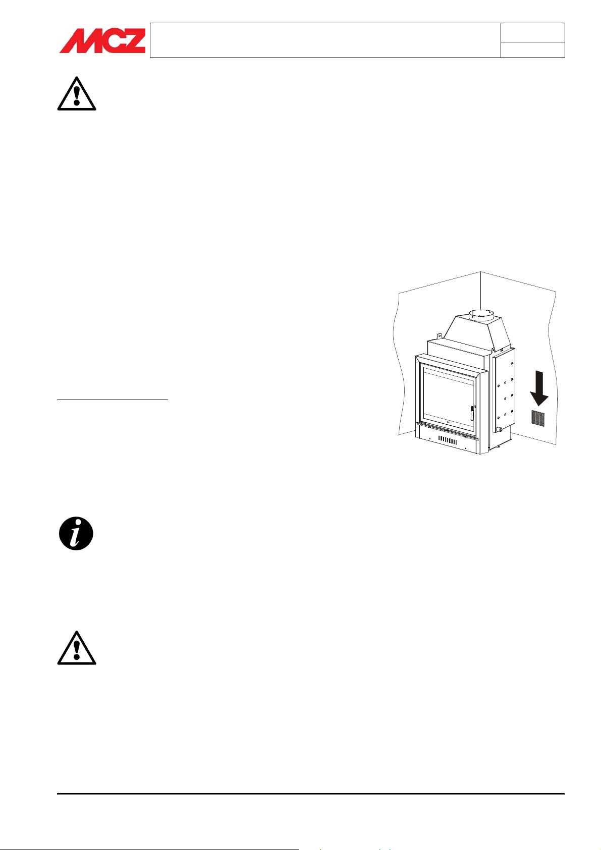
2.3. EXTERNAL AIR OUTLET
The room where the product is installed must have at least as much air
flow as required by the normal combustion of the appliance and normal
room ventilation. This may occur through permanent openings in the
room walls that lead directly outdoors or to ventilated rooms according
to UNI 10683 REV.
For this purpose, drill a hole on an exterior wall with a minimum free
section of 150 cm² (a 15 cm diameter hole or a 10x15cm rectangle),
protected by an indoor and outdoor grille.
The air intake must also:
• directly communicate with the installation room;
• be protected by a grille, made of metallic anti-insect mesh or a
suitable protection as long as it does not reduce the minimum
section:
• be installed so as to avoid obstruction;
• in the event of conduits, up to 3.5 ml, increase the section by
about 5%, while for larger sizes increase it by 15%.
Remember that the ventilation grilles always have a cm
useful section on one side. When selecting the grille and
hole dimensions, make sure the useful grille section is
greater than or equal to the section required by MCZ for
product operation.
2
Chapter 2
page
7
Connecting the air intake directly to the product is not
mandatory but the aforesaid section must guarantee about
50 m³/h of air. See standard UNI10683 REV.
IMPORTANT!
Air flow may also be obtained from a room adjacent
to the installation room as long as this flow occurs
freely through permanent openings that
communicate directly with the outdoors; avoid air
intakes connecting with heating units, garages,
kitchens or bathrooms.
Theoretical concepts for installation Technical service - MCZS.p.A. all rights reserved - Reproduction prohibited
INSTALLATION AND USE MANUAL
2.4. CONNECTION TO THE FLUE PIPE
Chapter 2
page
8
The connection to the flue pipe is a very important element. The
connection must be made with great care and attention, because it will
be very difficult to correct any construction anomalies or errors without
damaging the hood. The connection is also made in a part of the
fireplace where temperatures are very high, and thus it is important to
use heat-resistant materials that are also resistant to the acidity of the
fumes produced by combustion.
Before beginning work it is necessary to pay attention to the following
points:
• The connecting pipe must have a maximum slope of 45
degrees. This is to avoid excessive deposit of condensation
produced in the initial phases of lighting the fireplace heating
system and/or the excessive accumulation of creosote. It also
avoids slowing down the evacuation of fumes.
• The connections must be metallic in aluminium-clad
steel with minimum thickness 20/10 or in stainless
steel 316 with minimum thickness 10/10. The use of
flexible pipes in stainless steel or aluminium is
prohibited because it compromises the safety of the
connection itself. Flexible pipes are liable to split or
crack, causing leakage of smoke.
• The components making up the connecting pipe must be
perfectly sealed.
• The joint to the flue pipe must not be too long (to avoid
obstructions), nor too short (to avoid smoke leakage).
If metal connecting pipes are used, it is essential
that they be insulated with suitable material such as
ceramic fibre matting in order to avoid deterioration
of the walls and the decorative hood.
IMPORTANT!
Any increase in the section of the connecting pipe
must be made immediately above the hood of the
insert and not part-way along the flue pipe.
Flue pipe
Hood grille
Max 45°
Flue gas
connection
Ceramic fibre
insulation
Example of insert connection
2.5. CHIMNEY FLUE
The chimney flue is a fundamental element in discharging smoke
and therefore must have the following requisites:
• It must be waterproof and thermally insulated.
• It must be made with suitable heat-resistant materials that are
also resistant to combustion products and any condensation.
• It must have a vertical slope with axis deviations not over 45°
and without narrowing.
• It must meet the requisites indicated in the technical table for
the internal chimney section and height.
• It must preferably have a circular interior section.
• If pre-existent and previously operative, it must be clean.
Theoretical concepts for installation Technical service - MCZS.p.A. all rights reserved - Reproduction prohibited
Illustration of a correctly constructed
chimney flue with a chamber and sealed
door for solid combustion product collection
and discharge at the foot of the external
ascending segment.

INSTALLATION AND USE MANUAL
Chapter 2
page
9
The chimney flue is of primary importance for the
correct operation and safety of your insert.
Theoretical concepts for installation Technical service - MCZS.p.A. all rights reserved - Reproduction prohibited
INSTALLATION AND USE MANUAL
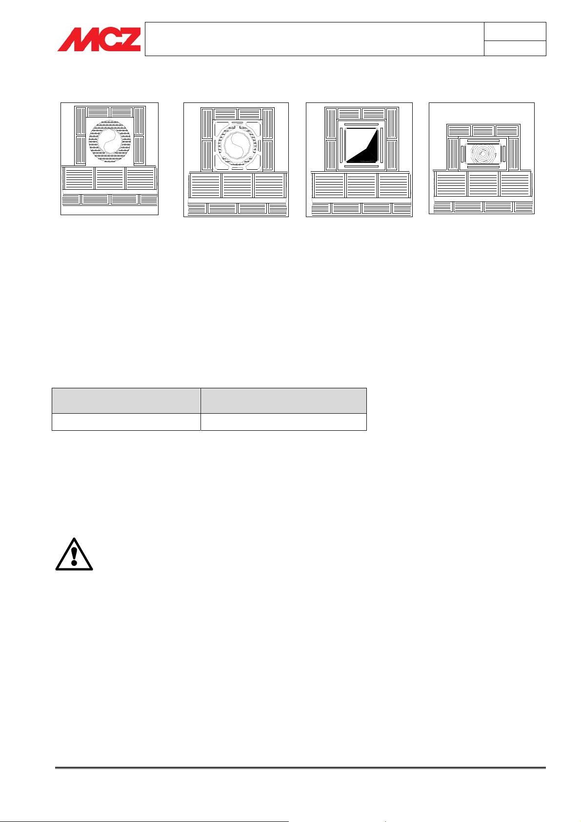
2.5.1. Examples of chimney flues
Chapter 2
page
10
AISI 304 stainless steel chimney
flue with dual chamber insulated
with ceramic wool or equivalent
resistant to 400°C.
EXCELLENT
Refractory chimney flue with
dual insulated chamber and
external concrete sleeve and
lightweight clay type
honeycomb material.
GOOD
Traditional square section clay
chimney flue with insulating
hollow inserts.
AVERAGE
Square or rectangular section chimney flues must have rounded
internal corners with radius not less than 20mm. For the rectangular
section, the ratio between internal dimensions must be ≤1.5.
The recommended section for a chimney flue according to its length is
listed in the table below:
Height (m) Section (cm²)
3 mt or more
400 (20x20 cm or ∅ 20 cm)
N.B. Too small or too large a section reduces draught and insulation.
For special sections or section or travel variations, functional smoke
exhaust inspections must be conducted as per UNI 9615.
The smoke conduit should be equipped with a solid material collection
chamber at the mouth of the smoke conduit to be easily opened with
an airtight door.
IMPORTANT!
If you have any doubts about your chimney flue
performance or if its dimensions are different from
those recommended, we highly advise you have an
authorised MCZ technician inspect and measure
chimney flue performance (micromanometer
measurements).
MCZ s.p.a. is not liable for poor product operation if
attributable to the use of a poorly dimensioned
chimney flue or installation of the same which fails
to meet the listed requirements.
Avoid chimney flues with
internal rectangular sections
whose larger side is double the
smaller such as 20x40 or
15x30.
POOR
Theoretical concepts for installation Technical service - MCZS.p.A. all rights reserved - Reproduction prohibited
INSTALLATION AND USE MANUAL
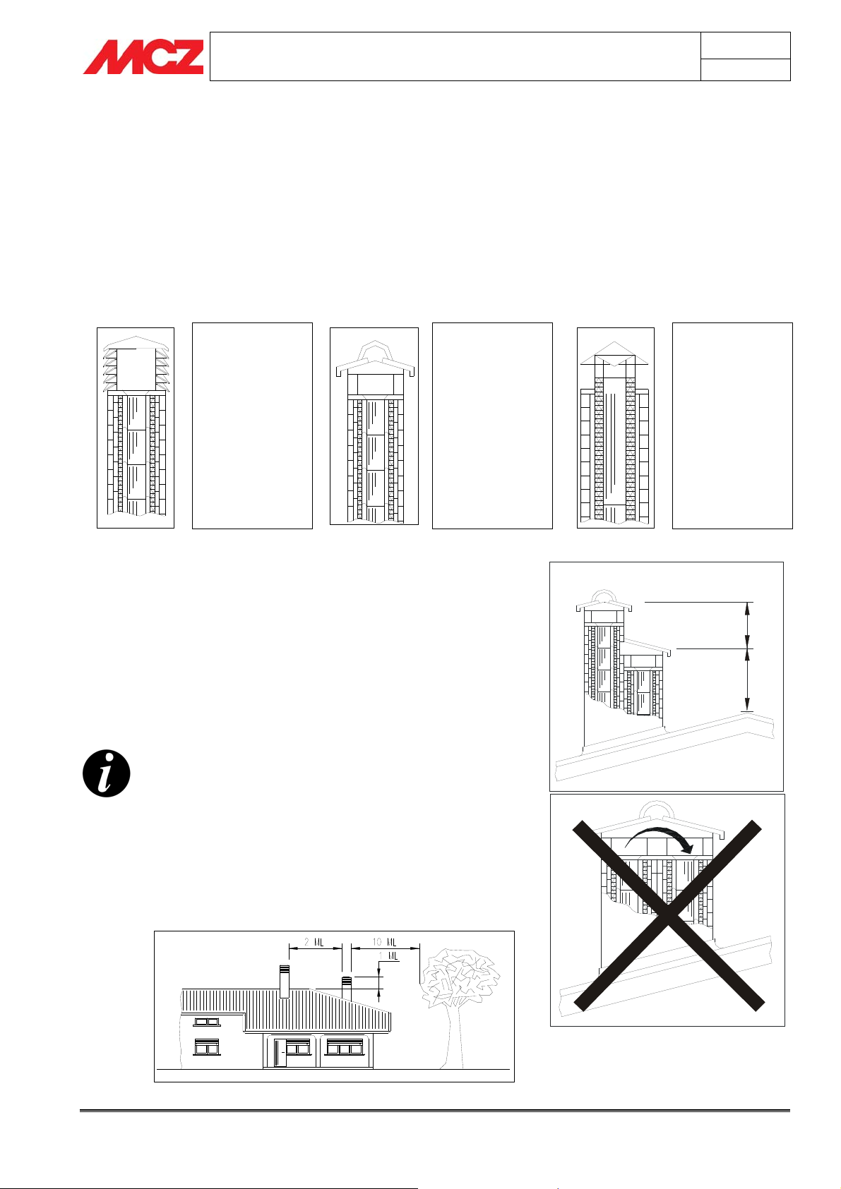
2.6. CHIMNEY POT
If underestimated, it is a terminal impediment to correct "chimney
system" operations.
Chimney flue draught is also a function of its chimney pot.
Therefore, if hand made, its four exhaust sections must correspond to
more than twice the internal section of the chimney flue.
Having to exceed the peak of the roof, the chimney pot will be
exposed to wind from all directions, thus an industrial type is
recommended.
Industrial chimney
pot with overlapping
prefabricated
elements.
Permits excellent
smoke exhaust.
Traditional hand
made chimney pot.
The right exhaust
section must be at
least twice the
internal section of
the chimney flue,
2.5 times is ideal.
Chapter 2
page
11
Steel chimney pot
for chimney flue with
internal smoke
deflector cone.
Permits excellent
smoke exhaust.
Chimney pots must meet the following requirements:
• It must have an internal section equal to that of the chimney.
• It must have a useful outlet section not less than twice that of
the internal section of the chimney flue.
• It must be built to prevent rain, snow and any foreign object
from getting into the chimney flue.
• It must be installed so as to guarantee suitable smoke
dispersion and, in any case, out of the reflux area where
counter-pressure formation is probable.
For paired chimney flues, the chimney pot for solid
combustion or the one for the upper floor must be at
least 50cm higher than the other to avoid pressure
transfers between paired flues.
The chimney pot must not have obstacles within 10 mt
such as walls, roof pitches or trees. Otherwise, raise it
at least 1 mt above the obstacle and, in the event of
other nearby chimney pots, keep them at least 2 mt
apart. In any case the chimney pot must exceed the
peak of the roof by at least 1mt.
t
m
5
,
0
t
m
1
Theoretical concepts for installation Technical service - MCZS.p.A. all rights reserved - Reproduction prohibited
0
INSTALLATION AND USE MANUAL
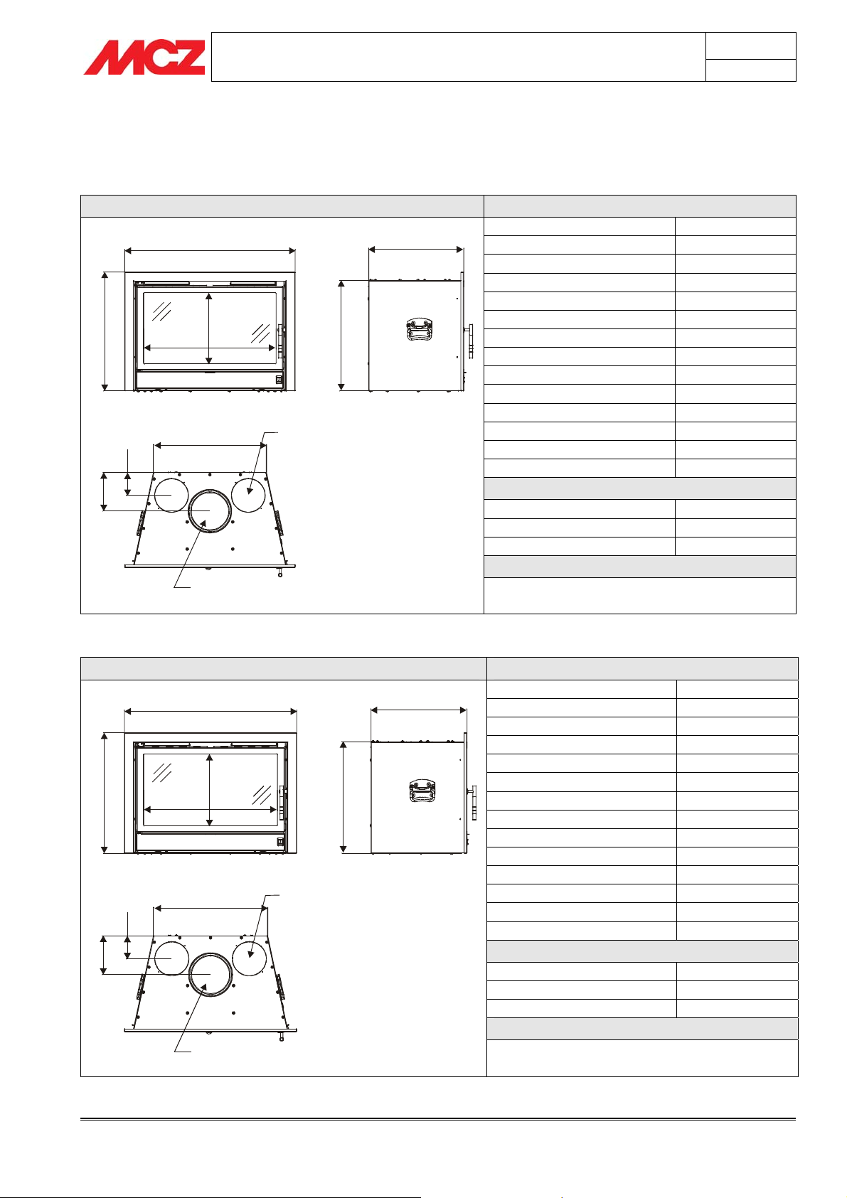
3. DIMENSIONS AND TECHNICAL SPECIFICATIONS
3.1. SMARTBOX
SmartBox F70 Technical specifications
Fuel type Wood - Chips
756
5
587
1
3
0
9
4
8
2
5
USCITA ARIA
1
500
0
1
1
7
1
CALDA Ø15 0
USCITA FUMI Ø 18
SmartBox F80 VN - VF Technical specifications
856
5
687
1
4
0
2
5
8
6
5
USCITA ARIA
0
578
0
1
1
7
1
CALDA Ø150
USCITA FUMI Ø 180
420
470
Hourly consumption 3.2 kg/h – 2.2 kg/h
Maximum thermal power kW 8.7 Kcal 7482
Minimum thermal power -
Efficiency 65%
Heatable volume * 187/40-214/35-249/30
Minimum draught 12 Pa / 0.12 mbar
Smoke temperature 400°C
Smoke outlet Ø 16 cm
Firebox dimensions 500x420
Net weight 100 Kg
External combustion air outlet cm² 150
CO2 emission in smoke (13 %O2) 0,22%
Mass throughput of smoke 13.55 g/s
Chimney flue
Up to 5 mt 20x30 cm Ø22
Between 5 and 7 mt. 20x20 cm Ø20
Over 7 mt 18x18 cm Ø18
Note
The insert is an intermittent combustion device
* Data may vary according to the fuel used
Fuel type Wood - Chips
Hourly consumption 3.2 kg/h – 2.2 kg/h
Maximum thermal power kW 8.7 Kcal 7482
Minimum thermal power -
Efficiency 65%
Heatable volume * 187/40-214/35-249/30
Minimum draught 12 Pa / 0.12 mbar
Smoke temperature 400°C
Smoke outlet Ø 16 cm
Firebox dimensions 578x470
Net weight 100 Kg
External combustion air outlet cm² 150
CO2 emission in smoke (13 %O2) 0,22%
Mass throughput of smoke 13.55 g/s
Chimney flue
Up to 5 mt 20x30 cm Ø22
Between 5 and 7 mt. 20x20 cm Ø20
Over 7 mt 18x18 cm Ø18
Note
The insert is an intermittent combustion device
* Data may vary according to the fuel used
Chapter 3
page
12
Technical features and technical specifications Technical service – MCZ S.p.A. all rights reserved - Reproduction prohibited

INSTALLATION AND USE MANUAL
Chapter 3
page
13
3.2. CLIMASYSTEM
Climasystem F60 Technical specifications
Fuel type Wood - Chips
Hourly consumption 2.4 kg/h – 1.6 kg/h
Maximum thermal power kW 6.5 Kcal 5590
Minimum thermal power -
Efficiency 63%
Heatable volume * 140/40-160/35–186/30
Minimum draught 12 Pa / 0.12 mbar
Smoke temperature 330°C
Smoke outlet Ø 16 cm
Firebox dimensions 495x365
Net weight 100 Kg
External combustion air outlet cm² 150
CO2 emission in smoke (13 %O2) 0,20%
Mass throughput of smoke 11.2 g/s
Chimney flue
Up to 5 mt 20x30 cm Ø22
Between 5 and 7 mt. 20x20 cm Ø20
Over 7 mt 18x18 cm Ø18
Note
The insert is an intermittent combustion device
* Data may vary according to the fuel used
Climasystem 60 RH-LH Technical specifications
Fuel type Wood - Chips
Hourly consumption 2.4 kg/h – 1.6 kg/h
Maximum thermal power kW 6.5 Kcal 5590
Minimum thermal power -
Efficiency 63%
Heatable volume * 140/40-160/35-186/30
Minimum draught 12 Pa / 0.12 mbar
Smoke temperature 330°C
Smoke outlet Ø 16 cm
Firebox dimensions 495x365
Net weight 100 Kg
External combustion air outlet cm² 150
CO2 emission in smoke (13 %O2) 0,20%
Mass throughput of smoke 11.2 g/s
Chimney flue
Up to 5 mt 20x30 cm Ø22
Between 5 and 7 mt. 20x20 cm Ø20
Over 7 mt 18x18 cm Ø18
Note
The insert is an intermittent combustion device
* Data may vary according to the fuel used
Technical features and technical specifications Technical service – MCZ S.p.A. all rights reserved - Reproduction prohibited

INSTALLATION AND USE MANUAL
Climasystem F70 Technical specifications
Fuel type Wood - Chips
Hourly consumption 2.9 kg/h – 2 kg/h
Maximum thermal power kW 8.5 Kcal 7310
Minimum thermal power -
Efficiency 67%
Heatable volume * 140/40-160/35-186/30
Minimum draught 12 Pa / 0.12 mbar
Smoke temperature 340°C
Smoke outlet Ø 16 cm
Firebox dimensions 560x485
Net weight 140 Kg
External combustion air outlet cm² 150
CO2 emission in smoke (13 %O2) 0,19%
Mass throughput of smoke 11.8 g/s
Chimney flue
Up to 5 mt 20x30 cm Ø22
Between 5 and 7 mt. 20x20 cm Ø20
Over 7 mt 18x18 cm Ø18
Note
The insert is an intermittent combustion device
* Data may vary according to the fuel used
Climasystem 70 RH-LH Technical specifications
Fuel type Wood - Chips
Hourly consumption 2.9 kg/h – 2 kg/h
Maximum thermal power kW 8.5 Kcal 7310
Minimum thermal power -
Efficiency 67%
Heatable volume * 140/40-160/35-186/30
Minimum draught 12 Pa / 0.12 mbar
Smoke temperature 340°C
Smoke outlet Ø 16 cm
Firebox dimensions 560x485
Net weight 140 Kg
External combustion air outlet cm² 150
CO2 emission in smoke (13 %O2) 0,19%
Mass throughput of smoke 11.8 g/s
Chimney flue
Up to 5 mt 20x30 cm Ø22
Between 5 and 7 mt. 20x20 cm Ø20
Over 7 mt 18x18 cm Ø18
Note
The insert is an intermittent combustion device
* Data may vary according to the fuel used
Chapter 3
page
14
Technical features and technical specifications Technical service – MCZ S.p.A. all rights reserved - Reproduction prohibited

INSTALLATION AND USE MANUAL
Climasystem E70 Technical specifications
Fuel type Wood - Chips
Hourly consumption 2.9 kg/h – 2 kg/h
Maximum thermal power kW 8.5 Kcal 7310
Minimum thermal power -
Efficiency 67%
Heatable volume * 140/40-160/35-186/30
Minimum draught 12 Pa / 0.12 mbar
Smoke temperature 340°C
Smoke outlet Ø 16 cm
Firebox dimensions 560x485
Net weight 145 Kg
External combustion air outlet cm² 150
CO2 emission in smoke (13 %O2) 0,19%
Mass throughput of smoke 11.8 g/s
Chimney flue
Up to 5 mt 20x30 cm Ø22
Between 5 and 7 mt. 20x20 cm Ø20
Over 7 mt 18x18 cm Ø18
Note
The insert is an intermittent combustion device
* Data may vary according to the fuel used
Chapter 3
page
15
3.3. SUPERCLIMA
Superclima F70 Technical specifications
695 450
8
9
4
8
6
6
0
7
1
212,5212,5 270
5
,
7
6
1
0
6
1
Ø
0
0
1
Ø
265
Fuel type Wood - Chips
Hourly consumption 3.1 kg/h – 2.1 kg/h
Nominal thermal power kW 9 Kcal 7740
Efficiency 66,5%
Heatable volume* 194/40-221/35-258/30
Minimum draught 12 Pa / 0.12 mbar
Smoke temperature 350°C
Smoke outlet Ø 16 cm
Firebox dimensions 59x35 H31.5 cm
Net weight 140 Kg
External combustion air outlet cm² 150
CO emission in smoke (13 %O2) 0,12%
Mass throughput of smoke 13.6 g/s
Chimney flue
Up to 5 mt 20x30 cm Ø22
Between 5 and 7 mt. 20x20 cm Ø20
Over 7 mt 18x18 cm Ø18
Note
The appliance is an intermittent combustion device.
* Data may vary according to the fuel used
Technical features and technical specifications Technical service – MCZ S.p.A. all rights reserved - Reproduction prohibited

INSTALLATION AND USE MANUAL
Superclima F80 Technical specifications
795 500
0
0
6
0
7
7
0
7
1
262,5262,5 270
5
,
7
6
1
0
6
1
Ø
0
0
1
Ø
265
Fuel type Wood - Chips
Hourly consumption 3.5 kg/h – 2.4 kg/h
Nominal thermal power kW 10 Kcal 8600
Efficiency 66,5%
Heatable volume * 215/40-246/35-287/30
Minimum draught 12 Pa / 0.12 mbar
Smoke temperature 360°C
Smoke outlet Ø 16 cm
Firebox dimensions 69x40 H40 cm
Net weight 150 Kg
External combustion air outlet cm² 150
CO emission in smoke (13 %O2) 0,12%
Mass throughput of smoke 13.6 g/s
Chimney flue
Up to 5 mt 20x30 cm Ø22
Between 5 and 7 mt. 20x20 cm Ø20
Over 7 mt 18x18 cm Ø18
Note
The appliance is an intermittent combustion device.
* Data may vary according to the fuel used
Chapter 3
page
16
Technical features and technical specifications Technical service – MCZ S.p.A. all rights reserved - Reproduction prohibited

INSTALLATION AND USE MANUAL
4. Installation and assembly
IMPORTANT!
The insert must be installed and connected to the
chimney flue by specialised technicians or skilled
personnel so that every local or national regulation is
met and, in any case, in accordance with the
standard UNI 10683 REV.
When the insert is unpacked, make sure all parts are in perfect
working order and check for damages due to transport. If the
insert is being installed in a place with difficult access, it is possible to
lighten the weight by removing the internal components which make up
the firebox. Remember to correctly reassemble all elements.
Any disassembly and assembly of internal parts
must, however, be carried out by skilled and
authorised personnel.
MCZ will not be held liable for any breakage in the
event the aforesaid warning is not observed.
Chapter 4
page
17
4.1. PREPARATION AND UNPACKING
Open the packaging, take off the bands, remove the insert from the
pallet and position it in the chosen location, taking care that its position
fully complies with the instructions.
The insert must always be kept in a vertical position during handling,
using the appropriate handles located on the sides. Be careful that the
door and its glass are protected from impacts that could jeopardise
their integrity. In any case, the product must always be handled with
care. If possible, unpack the insert in the area where it is to be
installed.
The materials which make up the packaging are not toxic or harmful,
so no special disposal procedures are required.
The end user must store, dispose of or recycle packaging material in
accordance with current regulations.
4.2. MAKING THE ELECTRICAL CONNECTIONS
Before positioning the insert, a 230V - 50 Hz electrical power outlet
must be prepared near the insert in order to connect the electrical cable
that powers the fans.
The power outlet must be equipped with an earth connection.
The wiring must be carried out by first cutting off the
electricity supply in the home.
When preparing the connection of the electrical cable
provided with the insert, be very careful not to crush
the cable while inserting the product. This could
cause short circuits that can damage the entire
electrical system.
Packaging example
Installation and assembly Technical service – MCZ S.p.A. all rights reserved - Reproduction prohibited

INSTALLATION AND USE MANUAL
4.3. GENERAL ASSEMBLY RULES
The insert can either be inserted on existing fireboxes or inserted as an
autonomous firebox thanks to its self-supporting structure.
If the insert is positioned in an existing firebox,
check that the dimensions of the firebox are
compatible for insertion.
If the insert is positioned over a floor or close to
walls made of flammable materials, these surfaces
should be suitably insulated in a safe manner.
The Superclima model has special requirements for
positioning and assembly. The installer should refer
to section 4.5
4.4. ASSEMBLY OF THE INSERTS (all models)
To facilitate insertion of the insert, especially on an irregular existing
firebox surface, the optional INSERTION GUIDE FRAME can be
used, while the flue gas connection can be made using the optional
.
TELESCOPIC CONNECTION
the SmartBox model.
For this operation just fix the frame (A) to the firebox surface using the
plugs (D) provided and, if necessary, use shims to level the frame.
Together with the insertion guide it is recommended to also use the
telescopic connection (B) that can be screwed onto the insertion guide
using the anchorings (C) and allows to make the connection to the
chimney flue before inserting the product
The "Insertion guide" and "Telescopic connection"
accessories are not available for the Smartbox
model.
These accessories are not available for
(see section 4.5.2)
Chapter 4
page
18
B
C
A
D
Insertion guide positioning and telescopic
connection
4.5. CONNECTION TO THE CHIMNEY FLUE (all models)
We recommend connecting the insert to the chimney flue using pipes
and bends in aluminium-clad steel, capable of withstanding the high
temperatures reached in that section of pipe and resisting corrosion
from the fumes. These connecting pipes are available on request in
various sizes (see MCZ accessories), and they simplify installation since
they are assembled by fitting one into another.
Flexible pipes in steel or aluminium cannot be used
to connect the insert to the chimney flue as they are
prohibited by current regulations.
4.5.1. Direct connection between insert and flue
pipe
Drill and disassemble the existing clay hood and engage the elements
in the chimney flue, being careful not to exceed the 45° inclination and
to correctly carry out any infilling necessary in order to prevent soot or
ashes of the chimney flue from settling above the insert.
(Figure 3)
Infill of direct flue gas connection
Installation and assembly Technical service – MCZ S.p.A. all rights reserved - Reproduction prohibited

A
INSTALLATION AND USE MANUAL
4.5.2. Connection using the telescopic connection
To simplify assembly of the insert it is possible to use the telescopic
connection, an optional accessory that MCZ makes available to its
installers and that allows to easily install the flue gas connection and
the SmartBox.
The telescopic connection can be fixed to the top part of the prehood
ring and, thanks to this accessory, the smoke outlet of the insert is
precisely determined and it is possible to freely create the entire
connection to the chimney flue without being obstructed by the volume
of the machine.
Once the connection has been completed, seal the section between the
pipe and entrance with refractory mortar or ceramic fibre. This
operation requires great care, and the seal must be airtight
since any passage of air may compromise the draught.
Any increase in the section of the connecting pipe
must start immediately above the hood of the
fireplace and not part-way along the flue pipe
section
When the installation is complete, the connecting
pipe must be insulated with ceramic fibre or other
material capable of withstanding temperatures of at
least 600 °C.
When the infilling operations are finished and the product is inserted,
just extract the upper deflector from inside the fire mouth of the
SmartBox, insert your hand inside the smoke outlet of the insert, turn
the handle inside the telescopic connection and pull downwards. The
telescopic connection will descend perfectly to the smoke outlet of the
SmartBox, thus completing the connection to the chimney flue.
(figure 4)
Infill of flue gas connection
Chapter 4
page
19
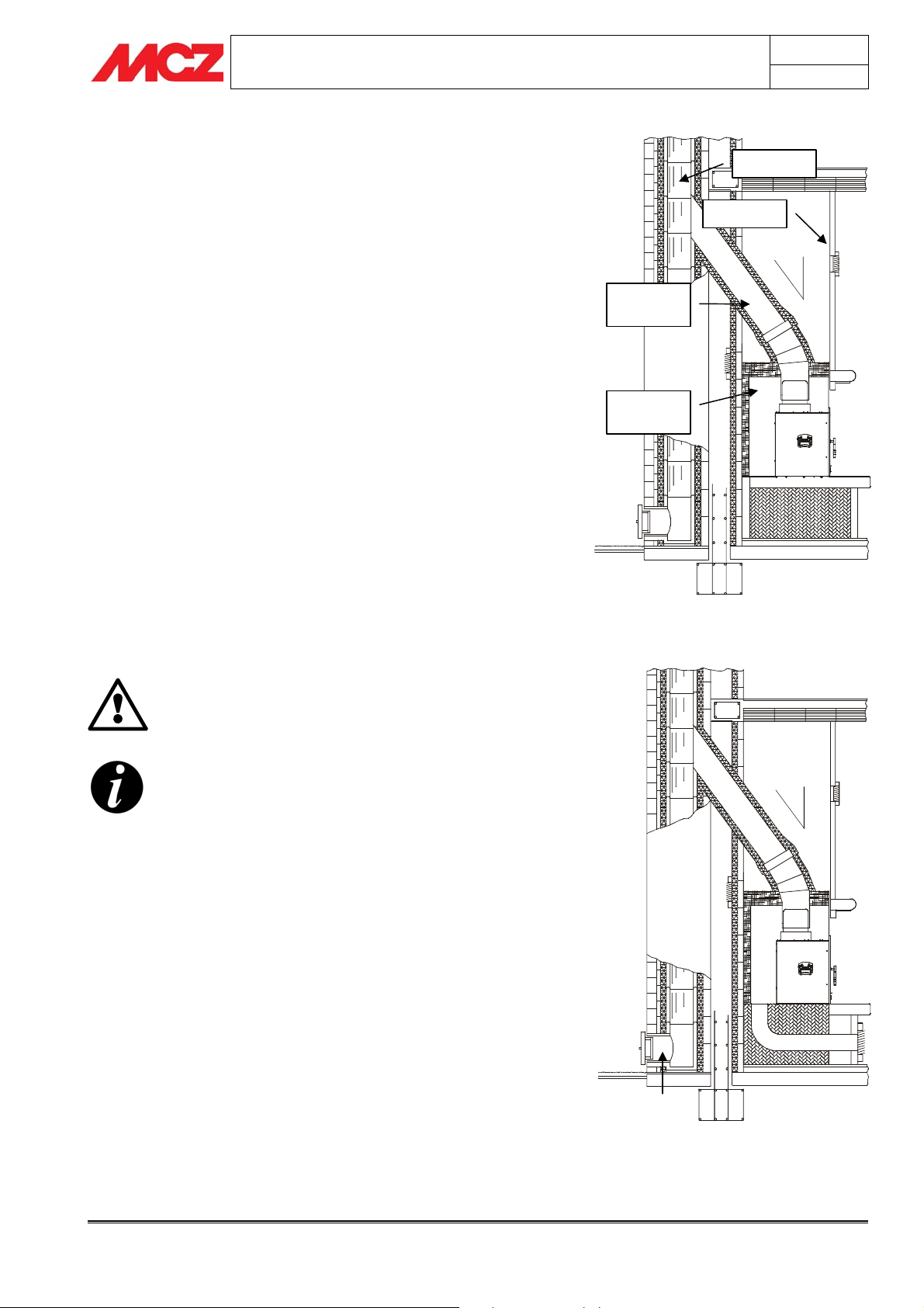
4.6. PARTICULARITIES OF THE SUPERCLIMA MODEL
Unlike the SmartBox and ClimaSystem inserts, the Superclima has a
compartment (M) located under the insert that contains the fan. This
compartment can be used as a support if cladding is built around the
self-supporting structure of the insert, or it must be inserted on the fire
bed of the firebox if Superclima is used to recover an old fireplace.
4.6.1. Superclima as a self-supporting structure
For those who are building the entire fireplace structure around the
Superclima or have an existing fire mouth available which is large
enough to allow full-height assembly of the insert, the two front
support brackets (B), provided in the package, can be used to balance
the structure which rests only on the fan compartment box.
For installation, unscrew the two front screws (A), attach the supports
(B) as shown in the figure and screw the screws (A) back on.
Otherwise, for those who are unable to use this installation procedure,
proceed as described in the following section.
4.6.2. Insertion of Superclima in a firebox
To install Superclima inside a firebox, first of all you must disassemble
the motor housing (M) and all the internal components
according to diagram 1 and create the compartment to hold this
A
B
Installation and assembly Technical service – MCZ S.p.A. all rights reserved - Reproduction prohibited

component, enlarging the existing ash pit of the firebox or creating it
by drilling the fire bed.
The motor housing has the dimensions: L 270 x H 170 x D 265
You must also provide space for the connection of the two air ducts
with 100 mm diameter, to be connected to the flanges (P) of the motor
housing. Insert the motor housing (M) inside the hole that has been
made in the old fire bed of the firebox.
Now, during this phase, make the air duct connections for the fan by
connecting one end of the flexible piping to the flanges (P) and the
other to the air intakes prepared previously (see next page).
Make a hole as well for the passage of the electrical wiring (N-H) that
connects the control unit (Q) to the motor and the thermostatic probe.
A compartment distant from the hot body of the insert must also
be provided to house the control unit so that it can be accessed for any
maintenance
(see the “Ventilation assembly kit” section).
INSTALLATION AND USE MANUAL
L
M
Chapter 4
page
20
P
B
D
A
C
DIAGRAM 1 - Superclima internal components disassembly and assembly
Internal components disassembly/assembly procedures:
1. Extract the cast iron fire beds A
2. Take out the removable bottom C by unscrewing the screws B
3. Remove the deflector E by unscrewing the two screws D
4. Disconnect the probe cable H, unscrew the two nuts F and
extract the motor support G
5. Disconnect the fan motor cable N (mark the position of the
connectors) and
6. Unscrew the screws L that fasten the motor housing and
remove the housing.
7. To reassemble Superclima, repeat the operations in the reverse
order from 6 to 1.
Connect the air ducts as follows:
One of the two outside the home so that it can draw in fresh clean air
and the other inside the room where the insert is being installed. This
procedure allows for proper mixing of the air inside the installation
room and better cooling of the insert structure.
F
E
G
H
N
P
M
Q
Installation and assembly Technical service – MCZ S.p.A. all rights reserved - Reproduction prohibited

For those who do not have the possibility to perform this type of
connection, it is in any case required to connect both air ducts
regardless of whether they are both connected to the exterior or the
interior. Depending on the choice of connection, the operating
temperature will be slightly higher or lower than average, but this does
not compromise correct operation.
When the installation of the fan compartment box and air ducts is
finished, proceed to the next phases for connection of the chimney flue
and the ventilation kit.
All the ventilation components can be assembled
from inside the fire mouth of the insert except the
motor housing which, however, we have already
installed beforehand.
INSTALLATION AND USE MANUAL
(Figure 1)
4.7. HOT AIR OUTLET KIT ASSEMBLY for
CLIMASYSTEM and SMARTBOX
If it is desired to use additional fan-assisted air outlets, we can attach
one or two HOT AIR OUTLET KITs (optional)
assemble the hot air ducts, it is necessary to break through the semi-
sheared plugs (A), screw on the flanges (B) and insert the flexible
pipes (D) fastening them with the appropriate pipe clamps (E). At the
opposite end of the flexible piping, attach the adjustable air outlets (C)
which will later be fixed to the decorative hood.
It is advisable to:
• Position the hot air outlets at a height of at least 2 mt. above
the floor so that the hot air does not flow directly onto people.
• Insulate the air duct pipes.
• Do not exceed 1.5 mt of ducting for each outlet.
• It is advisable to insulate the ducting pipes to avoid the
vibrations transmitted by the fans and forced air and to
keep the outcoming air warmer.
The front hot air outlet cannot be excluded even
though in the SmartBox model, by manually turning
the fins located above the fire door, it is possible to
direct more hot air through the top outlet pipes and
the hood outlets.
(figure 5).
To
E
C
Hot air outlet kit assembly
Chapter 4
page
21
D
B
A
D
4.8. HOT AIR OUTLET KIT ASSEMBLY SUPERCLIMA
E
If it is desired to use additional fan-assisted air outlets, we can attach
one or two HOT AIR OUTLET KITs (optional).
To assemble the hot air ducts, it is necessary to break through the
semi-sheared plugs (A), screw on the flanges (B) and insert the
flexible pipes (D) fastening them with the appropriate pipe clamps (E).
At the opposite end of the flexible piping, attach the adjustable air
outlets (C) which will later be fixed to the decorative hood.
Installation and assembly Technical service – MCZ S.p.A. all rights reserved - Reproduction prohibited
C
F
B
A

It is advisable to:
• Position the hot air outlets at a height of at least 2 mt. above
the floor so that the hot air does not flow directly onto people.
• Insulate the air duct pipes.
• Do not exceed 1.5 mt of ducting for each outlet.
The Superclima model also provides the possibility to install appropriate
buffers (F), which deflect the air flow to convey it inside the duct
piping. We recommend those using the air ducts to assemble these
flow deflectors for improved air flow to the outlets.
To install the buffers, they must be inserted in the appropriate
openings (G) after removing the semi-sheared plugs, and then blocked
with the appropriate screws provided.
Installation of the buffers allows to divide the air flow, sending about
70% towards the air ducts and 30% towards the front hot air outlet
grille.
The front hot air outlet cannot be completely
obstructed since it is necessary to cool the front part
of the structure.
It is also advisable to insulate the ducting pipes to
avoid the vibrations transmitted by the fans and
forced air.
INSTALLATION AND USE MANUAL
G
F
Chapter 4
page
22
4.9. FORCED VENTILATION KIT ASSEMBLY for SUPERCLIMA
THE COMPANY IS NOT LIABLE FOR DAMAGES DUE
TO INCORRECT CONNECTIONS OR IMPROPER USE
OF THE DEVICE.
The Superclima insert is supplied with a forced ventilation kit including:
(1) Radio control complete with internal battery
(2) Fan cable with plug and terminals
(3) Power supply cable with plug and socket
(4) FC700 or FC715 control unit with built-in radio receiver
3
(5) Centrifugal fan 300m
(6) Probe cable with rapid coupling connector and thermostat (MODEL FC700) or
(7) Probe cable with rapid coupling connector and thermostat (MODEL FC715)
/h 220v-50Hz
Installation and assembly Technical service – MCZ S.p.A. all rights reserved - Reproduction prohibited

INSTALLATION AND USE MANUAL
Chapter 4
page
23
4
Forced ventilation kit
3
6
Yellow-green
Brown
Blue
Once all the installation phases have been completed for the connection
to the chimney flue, the compensation kit (if applicable) and the beam
protection kit, it is now possible to definitively insert Superclima inside
the firebox.
The insert, however, has all its internal parts disassembled so it is
necessary to reassemble them properly, beginning with the ventilation
(figure 5),
kit
1. Connect the electrical cable (2) coming from the control unit to
2. Connect the electrical cable of the thermostatic probe (6) to
3. Probe connection for the FC715 control unit
4. Insert the fan motor (5) in the motor housing and connect the
5. Connect the control unit (4), located externally as specified in
Installation and assembly Technical service – MCZ S.p.A. all rights reserved - Reproduction prohibited
1
following the steps below:
the fan motor, as illustrated in
the cable coming from the control unit
Insert the probe M complete with support screws
(D+F+G+H+L) in the hole E following the procedure below:
(figure 7).
Screw the probe setscrew L onto the probe support G
without tightening, placing the bushing H in between.
Insert the entire probe support G+H+L in the hole E, inserting
the washer F beforehand and blocking the assembly with the
nut D from the side opposite the support.
Insert the probe M in the hole of the probe setscrew L
completely and gently tighten the screw L.
air ducts to the flanges.
section 4.2.2, to the home power distribution network and make
sure that the red LED located on the control unit turns on.
2
figure 5
(figure 5)
Probe assembly for the FC715 control unit
5
D
E
F
G
H
L
M

INSTALLATION AND USE MANUAL
CAUTION !!
• The control unit must be positioned in an accessible
location far from the insert
(see section 4.2.2)
to allow any
necessary maintenance or replacement of the internal fuse.
• The equipment must be powered with a voltage of 220 V
at 50 Hz and the power outlet must be accessible and
complete with an earth connection.
• Make sure that the cables do not come into contact with
the hot metal parts of the structure, as they could melt
and short circuit the electrical system.
• The equipment must be connected to a bipolar switch
complete with fuses.
Example of control unit positioning
Once the assembly of the ventilation kit is completed,
reassemble the fire bed and the internal components
according to the diagram and description of figure 1 on page
17.
4.10. PERFORATED COMPENSATION FRAME KIT
ASSEMBLY
Chapter 4
page
24
If there is a space of more than 1 cm between the insert and the
existing firebox, the appropriate compensation frame kit can be
installed which uses a frame in perforated aluminium-clad steel to fill
the cavity between the insert and the firebox.
The MCZ compensation frame has a standard width of 10 cm, while
the length is determined by the perimeter of the product being
installed.
Before inserting the unit, it is necessary to measure the exact
dimensions of the frames, cut them if necessary with sheet metal
scissors if they are too large and fix them with the appropriate selftapping screws in the holes already arranged on the outer sides and
roof of the Superclima insert.
Only after the compensation kit has been sized and assembled can the
insert be definitively inserted inside the firebox.
4.11. COMPENSATION FRAME ASSEMBLY
The SmartBox and SuperClima models (not available for the
ClimaSystem) also provide the possibility to assemble an exterior
finishing frame that covers all four sides of the product.
This (optional) frame is assembled only after the installation and
cladding are complete, and it anchors directly to the insert structure.
This frame is designed to finish and cover the crack that is formed
between the metal structure of the unit and the wall.
To assemble the frame, just open the fire door, fit the frame as shown
in the figure and use the four screws provided to fix it onto the stiles of
the structure, inside the profile of the door.
Compensation kit assembly
4.12. BEAM PROTECTION KIT ASSEMBLY
If there is a beam made of wood or other combustible material above
the hot air outlet opening, it is absolutely necessary to protect it
Installation and assembly Technical service – MCZ S.p.A. all rights reserved - Reproduction prohibited
Compensation frame assembly

g
INSTALLATION AND USE MANUAL
with the BEAM PROTECTION KIT (optional) or with panels made of
insulating material (Ex: calorite).
To attach the protection, fix the panel to the beam using the
appropriate wood screws provided.
(figure 7)
4.13. SUMMARY DIAGRAM FOR IDEAL CONNECTION
OF THE INSERTS
The installation described below is ideal for inserts assembled on old or
new fireplaces; the insert must never be walled up but kept 5mm
detached from any masonry surface since it needs to be able to expand
when it is hot; furthermore, if it is walled up there is a significant drop
(30÷40%) in the thermal efficiency because the heat is not allowed out
completely but only in part.
Insulate the structure thorou
parts in wood or flammable material nearby.
SMOKE CONNECTION
hly only if there are
Beam protection kit assembly
Chapter 4
page
25
*TOP INSULATION
N
O
I
T
A
L
U
S
N
I
R
A
E
R
*
)
E
G
N
A
H
T
C
C
X
U
E
D
E
R
I
H
A
T
N
R
O
O
I
F
T
L
C
U
E
F
V
E
N
S
O
U
C
(
BEAM
BEAM
INSULATION
CONVECTION
AIR OUTLET
VENTILATION
AIR OUTLET
COMBUSTION AIR INLET
VENTILATION AIR INLET
*
CALORITE
INSULATION
CONVECTION AIR INLET
*Insulation is possible with rigid panels in CALORITE
or similar insulating material.
COMPENSATION KIT
CONVECTION
AIR INLET
Installation and assembly Technical service – MCZ S.p.A. all rights reserved - Reproduction prohibited
SUPPORT IN MASONRY OR SIMILAR MATERIAL

INSTALLATION AND USE MANUAL
Chapter 4
page
26
Installation and assembly Technical service – MCZ S.p.A. all rights reserved - Reproduction prohibited

INSTALLATION AND USE MANUAL
5. OPERATION
5.1. PRE-LIGHTING WARNINGS
Make sure you have read and completely understood the contents of
this instruction booklet.
Remove all accessories and supplies which might burn (various
instructions and adhesive labels) from the firebox and door.
Remove the stickers from the ceramic glass or the high temperature
could melt them and irreparably damage the glass. In this case, the
MCZ warranty does not cover the glass.
Avoid touching the product the first time it is used since its
paint completes drying and hardens during the first lighting.
If you touch the paint, you may expose the steel surface.
It is good practice to provide plenty of ventilation in the room
during the initial lighting, as the product will give off a small
amount of smoke and smell of paint.
If necessary, touch up the paint with aerosol spray in the
original colour. (see the section "Accessories for fireplace
stoves and inserts").
Do not remain near the product and, as previously mentioned, ventilate
the room. The smoke and the smell of paint will vanish after about one
hour of operation. There are no health risks involved.
The structure will be subject to expansion and
contraction during the lighting and cooling down
stages, and may therefore make slight creaking
noises.
This phenomenon is absolutely normal, the structure
being made of sheet steel, and must not be
considered a fault.
Chapter 5
page
27
It is extremely important to be sure not to take the
product to full heat straight away, but to bring it
gradually up to temperature.
This avoids damages to seals and the steel structure.
Do not demand full heating
performance straight away!
5.2. FUEL
FUEL: Wood
To obtain the maximum performance from your product, it is of primary
importance to use wood with suitable characteristics.
It is possible to use firewood such as oak, beech, ash, robinia or
ilex, or manmade logs from compressed wood without added resins.
These have a high calorific value and must be used with
caution to avoid overheating which could damage the product.
Operation Technical service – MCZ S.p.A. all rights reserved - Reproduction prohibited

INSTALLATION AND USE MANUAL
Fuels such as poplar, pine, lime and chestnut have a low calorific value,
being soft woods, soft in the sense of being pulpy, and they do not
burn long. For all listed types, the humidity contained in them is a
fundamental factor.
A high percentage of moisture produces condensation in the
smoke duct causing an alteration in the draught and
generating smoke and a significant deposit of soot in the
firebox, on the glass of the door and in the flue pipe with a
possible risk of a chimney fire later on. It also causes a
considerable overall drop in efficiency.
The use of damp or treated wood emits a higher quantity of
smoke than normal that can dirty glass faster. Also the low
performance of the chimney flue can jeopardise glass
cleanliness since smoke remains in the combustion chamber
longer than normal.
Do not use treated fuels (such as painted or varnished
wood) or unsuitable materials (such as plastics and
derivatives), which could release toxic or polluting
substances.
Do not burn rubbish.
The gases produced by combustion based on the use
of unsuitable fuels cause damage to the product and
the chimney flue; they cause pollution and can
significantly compromise your health.
Chapter 5
page
28
Wood drying
time (i.e. beech)
Freshly cut 50 /
3 months 40 2410
6 months 35 2700
9 months 30 2900
12 months 25 3150
15 months 20 3400
18 months 15 3710
21 months 10 3980
humidity
%
Heat
power
Kcal/h
5.3. USE OF THE INSERT
5.3.1. LOADING THE FUEL
To load fuel, simply open the door by rotating/lifting the handle and
pulling the door open.
During use, the metal parts and the glass reach high temperatures, so
it is necessary to use the special thermal glove supplied.
During combustion, the combustion chamber door must remain
closed.
Loading quantities of fuel over those indicated in the
technical sheets for each single product is prohibited.
Excessive quantities of fuel in the combustion
chamber could damage and deform the firebox and
structure.
MCZ is not liable for any damages caused by
overloaded fuel or the use of fuel that does not meet
specifications.
5.3.2. COMBUSTION CONTROL
PRIMARY AIR
The insert is equipped with primary air emission from the part
underneath that guarantees proper combustion. Moving the lever
towards the base of the arrow provides total opening with a more rapid
combustion, while moving the lever towards the point of the arrow
provides partial closure with slower combustion.
Operation Technical service – MCZ S.p.A. all rights reserved - Reproduction prohibited

INSTALLATION AND USE MANUAL
SECONDARY AIR
The top part of the product provides emission of so-called secondary air
that produces post-combustion, increasing efficiency while reducing
polluting elements and helping to keep the glass clean. The same lever
used to adjust the primary air is used to proportionally dose the
secondary air in a calibrated manner, allowing the final user to enjoy
excellent combustion regulation.
5.3.3. FIRST LIGHTING
It is advisable to approach the first lighting with caution, using
good-quality, well-seasoned wood.
The combustion air entrance must be fully open.
Once combustion has started, normal-sized pieces of wood may be
added.
The flame must have as far as possible a smooth and laminar flow.
When reloading, the fire door should be opened slowly to avoid
blowbacks of smoke into the room.
Proceed as follows:
• Place a small amount of balled paper in the firebox.
• Cover the paper with a small quantity of twigs and a few
pieces of wood.
• Fully open the combustion air regulator.
• Light the paper and, if necessary, keep the door open for
several minutes until the combustion chamber and chimney
flue are heated.
• When the twigs are burning, the door can be closed.
As the fire burns, add wood. Never overload the product with wood
(see technical specifications in the table).
As soon as the flames have died down and a bed of embers has
formed, load the insert normally.
Small loads of wood are preferable to large ones for
combustion.
We recommend that this fuel loading method be used even during
subsequent product use.
To obtain nominal power, place the load of wood indicated
in the technical specifications table in the combustion
chamber (
hour. When the fire dies down, load the firebox again.
chapter 3
). The insert autonomy is about one
MIN
MAX
Chapter 5
page
29
Caution !
• Do not use volatile or flammable substances
(petrol, alcohol, etc.) for lighting the fire.
• Do not use fuels which could release toxic
substances or pollutants.
• Do not put the fire out by throwing water on it.
• Check the external-internal air intakes and the
chimney flue at least once a year, arranging for
them to be cleaned.
• During use, the metal parts and the glass reach
Operation Technical service – MCZ S.p.A. all rights reserved - Reproduction prohibited

INSTALLATION AND USE MANUAL
high temperatures. For all loading, adjustment or
ash cleaning operations, use the insulated glove
provided.
• Never leave children unattended near the insert
when it is in use.
• The risk of burns from contact with hot surfaces
is very high.
• In the event of poor weather conditions for
insert use (low pressure, moderate
temperatures, wind) back draught may occur in
the chimney flue. If this occurs, use a small
quantity of paper to heat the chimney flue and
restore normal draught. Afterwards, proceed
with normal product lighting.
5.4. FORCED VENTILATION OPERATION for the
SMARTBOX MODELS
The insert is equipped with two internal fans for forced propagation of
the air inside the cavities of the product. The fans are internally
mounted on the lower part of the insert structure.
The flow of hot air created by these fans is very slight in order
to keep the temperature of the air coming out of the outlet
very high and promote convection heating.
Using the control button located on the lower front panel
is possible to select the desired operation mode:
• Button on I = MANUAL operation
• Button on II = AUTOMATIC operation.
IT IS NOT POSSIBLE TO SWITCH THE VENTILATION
OFF IF THE INSERT IS ON; this is to prevent high
temperatures from damaging the structure.
(figure 10),
it
Fan control button.
Chapter 5
page
30
5.4.1. Manual operation
When the switch is positioned on I, the fans are always on, regardless
of whether or not there is a fire inside the mouth of the insert.
To switch the ventilation off, when the fire is out
, the switch must be
positioned on II; in fact, in this case the internal probe, if it is not at
temperature (~50°C), will not allow operation of the fans.
5.4.2. Automatic operation
When the switch is positioned on II the fans switch on/off exclusively
when the temperature of the probe is higher/lower than
50/60°C.
Operation Technical service – MCZ S.p.A. all rights reserved - Reproduction prohibited
SmartBox panel setscrews

INSTALLATION AND USE MANUAL
The probe has a high setting because it is designed to operate as a
probe for switching off the ventilation rather than a probe for
lighting. In fact, it is more convenient that the fans switch off
automatically when you are not near the insert rather than at the
beginning when it is still carrying out the initial lighting.
The temperature probe is located behind the On button; it is easily
accessible and can be checked by disassembling the front panel
(SmartBox) or taking off the fan box (Climasystem) by first removing
the screws that secure it.
To check that the probe works properly, position the button
on II, heat the probe with a hair dryer and wait for the fans
to switch off. In this manner you can check that the probe is
intact.
Never perform this check by subjecting the probe
directly to open flames (cigarette lighter, matches,
etc.) since this could irreparably damage the probe.
If the reaction times of the probe are too long, then you should check
why the structure takes a long time to increase its temperature.
Normally this phenomenon is caused by unsuitable wood or wood with
a low heat yield (see section
“4.10 Choice of fuel”
) or because the
performance of the chimney flue does not allow suitable discharge of
the fumes and a correct combustion.
Chapter 5
page
Climasystem ventilation box setscrew
31
5.5. SMARTBOX F80 VN NATURAL VENTILATION
The insert can also operate by natural convection, which means that
the flow of hot air can pass through the entire structure even without
the aid of fans. The Smartbox F80VN maintains as a hot air outlet the
two fins located above the fire door
(figure 6)
from which a natural air
flow will emerge at high temperatures that will be uniformly dispersed
throughout the room.
5.6. FORCED VENTILATION OPERATION for the CLIMASYSTEM MODELS
The only substantial difference between the ventilation of the
Climasystem and that of the Smartbox is represented by the fact that
the Climasystem model has three fans which are more powerful and
that the button has three positions instead of two.
The operating concept, on the other hand, is the same for the
two models.
• Position I = MANUAL operation
• Position 0 = OFF
• Button on II = AUTOMATIC operation.
5.7. FORCED VENTILATION OPERATION for the SUPERCLIMA MODELS
5.7.1. FC 715 control unit operation
The device allows the speed of the fan, which is controlled by the radio
remote control, to be regulated in one of two modes:
Operation Technical service – MCZ S.p.A. all rights reserved - Reproduction prohibited

INSTALLATION AND USE MANUAL
MANUAL The fan (5) runs at the set speed regardless of the
probe.
AUTOMATIC The fan (5) runs at the set speed with the consent of
the probe.
5.7.1.1. Radio remote control
The radio remote control has 4 buttons with which it is possible to
perform the following operations:
• On/off (blue button)
• Change operation mode from manual to automatic and vice
versa (red button)
• Variation of the 4 speeds of the fan (yellow buttons)
5.7.1.2. Switching on and off
SWITCHING ON: Prolonged pressure on the blue button of the
radio remote control switches on the fan at the
first speed in MANUAL mode. The control unit
emits one short beep that identifies the1
speed in manual mode.
SWITCHING OFF: Prolonged pressure on the blue button of the
radio remote control puts the device in STAND-
BY, which is signalled by 1 very long beep,
and stops the fan.
st
Chapter 5
page
32
5.7.1.3. Manual mode
In a predefined manner at the switch-on using the ON/OFF button or
through a simple click on the red MAN/AUT button, the system goes
into MANUAL mode. This mode can be recognized by the fact that all
the sound signals emitted by the control unit in this state are
short beeps and the fan is always on, regardless of the
temperature.
The yellow buttons + and - can be used to increase/decrease the fan
speed from the 1
responds with a number of beeps corresponding to the selected speed:
st
to the 4th speed and vice versa. The control unit
1st Speed = 1 short BEEP
nd
Speed = 2 short BEEPS
2
rd
Speed = 3 short BEEPS
3
th
Speed = 4 short BEEPS
4
Regardless of whether the insert is on or off, the ventilation switches
on and emits air according to the set speed.
5.7.1.4. Automatic mode
Once the ventilation has been switched on in manual mode, simply
pressing the red MAN/AUT button cause the device to go into
AUTOMATIC mode. This mode can be recognized by the fact that all
the sound signals emitted by the control unit in this state are
long beeps.
Operation Technical service – MCZ S.p.A. all rights reserved - Reproduction prohibited

INSTALLATION AND USE MANUAL
The yellow buttons + and - can be used to increase/decrease the fan
speed from the 1
responds with a number of beeps corresponding to the selected speed:
st
to the 4th speed and vice versa. The control unit
1st Speed = 1 long BEEP
nd
Speed = 2 long BEEPS
2
rd
Speed = 3 long BEEPS
3
th
Speed = 4 long BEEPS
4
The switching on and off of the ventilation is determined exclusively by
the temperature of the thermostatic probe.
AUTOMATIC SWITCH-ON BY THE PROBE:
If the temperature detected by the probe is above 45°C, the fan
switches on at the set speed (1
st
speed) and an internal timer is
activated which begins to count down a period of 40 minutes. This 40minute period is called the “
heating phase"
.
After the 40-minute period has passed, if the temperature of the probe
is above 65°C, this means that the internal temperature is rising
because the insert is in full operation and consequently the fan must
remain on. If instead the 40-minute period has passed and the probe
has not reached 65°C, this means that fire operation is low and thus
the ventilation should switch off.
If the user changes the speed while the system is between 45°C to
65°C, this is interpreted as the desire to ventilate and thus the system
returns to the
heating phase ,
resetting the timer to 40 minutes and
starting the countdown.
AUTOMATIC SWITCH-OFF BY THE PROBE:
If the temperature probe drops below 65°C, the ventilation switches
off.
Chapter 5
page
33
5.7.1.5. Other functions of the FC 715 control unit
• STAND-BY: The fan is off because the blue ON/OFF button of
the radio remote control has been pressed. This shutdown is
signalled by one long beep.
ON
OFF
MAN
AUT
• SAFETY: In the STAND-BY state, if the temperature exceeds
the value of 150°C, the fan is activated at speed 1 and the
system goes into AUTOMATIC mode. The ventilation continues
until the temperature drops below 65°C.
• STATUS RECOVERY: The system automatically stores the last
power set by the user in the non-volatile memory , allowing the
user to continue at this speed after a power failure.
BATTERY COMPART MENT
5.7.1.6. Setting the transmission code of the radio
AND SWITCH
remote control
The radio remote control and the control unit are set with a neutral
code that immediately allows control of the ventilation kit operation
before completion of the cladding.
It may become necessary, however, to change this code and thus the
transmission frequency in the event another fireplace heating system is
present nearby (ex.: a neighbour has one) or if other signal
interference creates transmission problems.
Operation Technical service – MCZ S.p.A. all rights reserved - Reproduction prohibited

INSTALLATION AND USE MANUAL
Chapter 5
page
34
Follow this procedure to personalize the code:
• Disconnect the control unit plug from the power outlet
Switch inside the battery compartment of the
radio remote control
• Open the battery compartment of the radio remote control by
operating on the door in the direction of the arrow
(figure 10)
• Raise any one or more of the 10 white keys as shown in the
example in
figure 11
• Close the radio remote control
• Press and hold pressed the red button of the radio remote
control and simultaneously reconnect the plug to the power
outlet.
• After a maximum time of 15 seconds, one prolonged beep or a
series of beeps in sequence will confirm the successful
connection between the radio remote control and the control
unit with the new code.
5.8. EMERGENCY TREATMENT
If for any reason the fire needs to be suddenly and quickly put out or a
fire in the chimney flue needs to be put out, proceed as follows:
• If time allows, remove the embers and ashes, using a metal
container.
• Put the fire out rapidly by means of a dry carbon dioxide (CO
extinguisher.
Operation Technical service – MCZ S.p.A. all rights reserved - Reproduction prohibited
)
2

INSTALLATION AND USE MANUAL
Chapter 5
page
35
Operation Technical service – MCZ S.p.A. all rights reserved - Reproduction prohibited

INSTALLATION AND USE MANUAL
6. MAINTENANCE AND CLEANING
CAUTION!
All cleaning operations of all parts should be
conducted when the product is off and completely
cold.
6.1. CLEANING TO BE PERFORMED BY THE USER
6.1.1. Cleaning the glass
Specific products can be used to clean the glass (see our pricelist), a
cloth dampened with water and ammonia or a bit of white ash and a
newspaper. Any soot and dirt accumulations take longer to clean.
CAUTION!
Do not spray the product on the painted parts or on
the gaskets of the door (ceramic fibre cord)
The ceramic glass installed on MCZ products are resistant to
temperatures of up to 750°C and are tested and inspected
before and after assembly to check for cracks, bubbles and
holes.
The glass, although highly resistant to elevated
temperatures, is a fragile element, and thus the door should
be handled with care without slamming or forcing it. Glass,
since it is not elastic, can break.
This type of glass does not burst or shatter but if it should
break, due to the above, it will only crack.
Chapter 6
page
36
6.1.2. Cleaning upper calorite deflectors
These do not require particular care. With prolonged use, however, the
effective but porous material of which the deflectors inside the firebox
are made can wear out or become damaged. They should be replaced
only when their thickness is reduced by half or they break.
6.1.3. Cleaning out the ashes
This operation should be performed with the insert off. Adequate ash
drawer cleaning is also recommended for correct combustion.
Ashes which are still hot must not be dumped outside in an
uncontrolled manner or put in the dustbin. Leave them to cool
down in the open air in a metal container.
6.1.4. Cleaning of stainless steel and satin-finish surfaces
Normally these surfaces do not need to be treated, but if they do,
avoid cleaning them with abrasive materials. For surfaces in stainless
and satin brushed steel, we recommend cleaning with a paper towel or
a clean dry cloth moistened with a detergent based on non-ionic
surfactants ( < 5%). A spray glass cleaner may be used.
6.1.5. Cleaning of painted parts
Do not clean the painted parts with wet rags when the unit is in
operation or hot in order to prevent thermal shock to the paint which
Maintenance and cleaning Technical service - MCZS.p.A. all rights reserved - Reproduction prohibited

INSTALLATION AND USE MANUAL
may cause it to detach. Do not use abrasive or aggressive products or
materials.
Clean with damp cotton or paper towels.
The silicone paints used to paint MCZ products have first-rate
technical properties that make them resistant to very high
temperatures.
There is, however, a physical limit (380°-400°) beyond which
the paint begins to loose its characteristics and fade or (over
450°) vitrify; it may then flake and detach from the steel
surface. If these effects are noticed, it means temperatures
have been reached that are well above those at which the
product should properly operate. Therefore, you should use
the amount of fuel specified in the technical tables.
6.1.6. Cleaning and characteristics of marble and
potstone cladding.
Potstone and marble are natural materials taken from
blocks of stone and then worked. Therefore, veins,
colour variations or other characteristics are natural
parts of the stone and should not be considered
defects.
It is important to clean the cladding carefully and
with the correct products. Cleaning incorrectly may
stain or damage the finish of the stone or marble.
Cleaning these materials is a very important and delicate process. It
must be done using specific products for treating stone/marble.
Carefully follow the instructions on the packages of the special products
used for cleaning. Generally, you should always use water-based
materials and a soft cotton cloth.
Chapter 6
page
37
6.1.7. Cleaning the chimney flue
Mechanical cleaning of the chimney flue is recommended at least once
a year. Excessive deposits of unburned solid material can cause
problems with the evacuation of smoke, and produces the risk of
chimney fires.
6.2. CLEANING BY SPECIALISED PERSONNEL
CAUTION:
The frequency with which the product is cleaned
should be determined based on the type of use that is
made of the product and the type of installation.
MCZ suggests relying on an authorised service centre
for end-of-season cleaning and maintenance, which
will carry out all of the previously mentioned work
and make a general check of the appliance's
components.
Maintenance and cleaning Technical service - MCZS.p.A. all rights reserved - Reproduction prohibited
 Loading...