

Page 1
INVERTER WALL MOUNTED SPLIT TYPE
AIR CONDITIONER (G Series)
INSTALLATION MANUAL
Group: INVERTER
Part Number: A08014078756
Date: FEBRUARY 2005
IM-WMXG-0205-McQuay
© 2005 McQuay International
Page 2
i
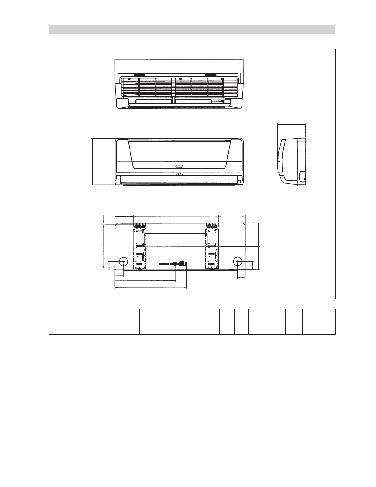
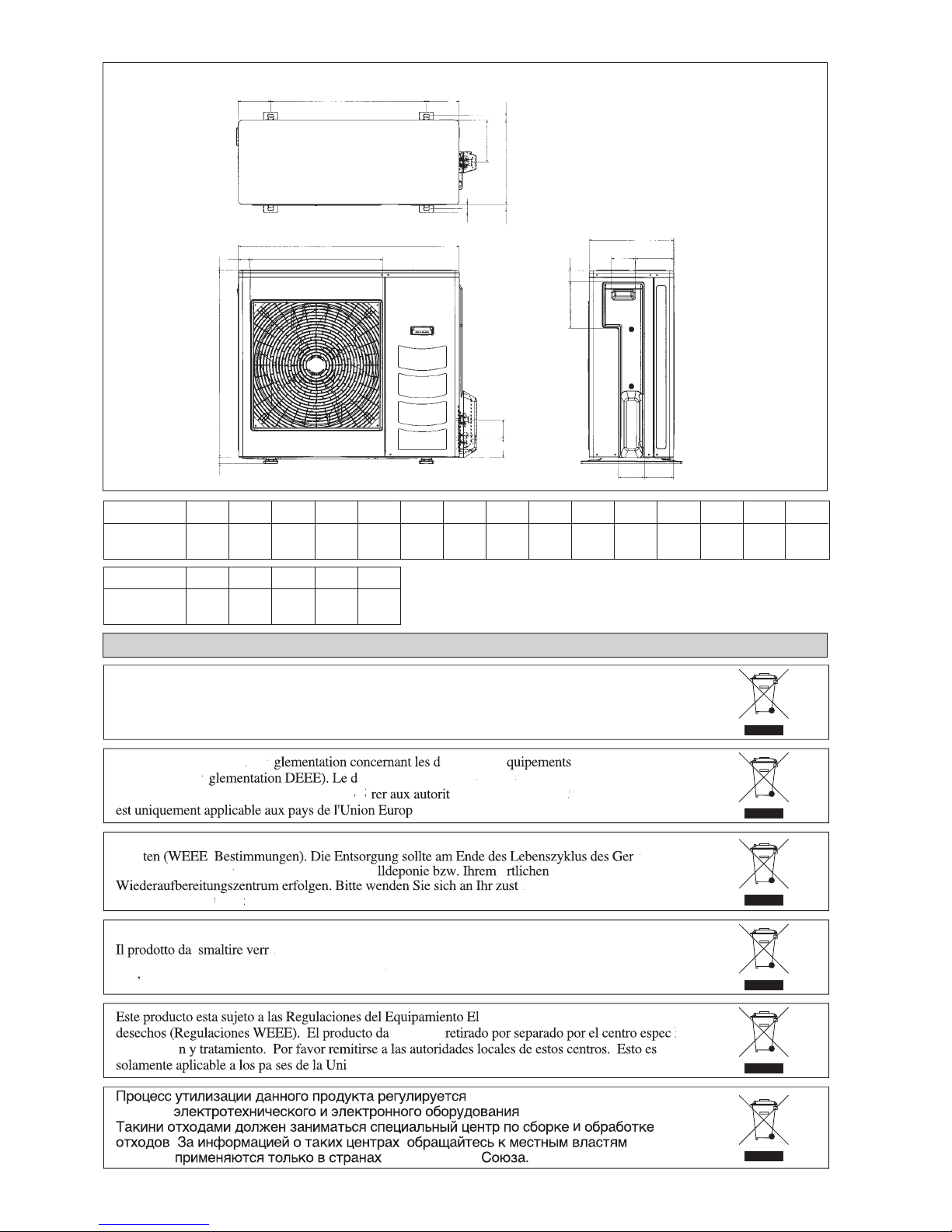
All dimensions are in mm / (in)
Indoor Unit (MWMXG Series)
OUTLINE AND DIMENSIONS
INSTALLATION
PLATE
Dimension A B C D E F G H I J K L M N O
10 / 15G / GR 899 260 198 590 246 185 124 8 56 50 419 495 50 128 132
(35,4) (10,2) (7,8) (23,2) (9,7) (7,3) (4,9) (0,3) (2,2) (2,0) (16,5) (19,5) (2,0) (5,1) (5,2)
A
B
FRONT VIEW
TOP VIEW
C
SIDE VIEW
D
F
G
E
H
O
N
I
I
J
K
L
M
Page 3
ii
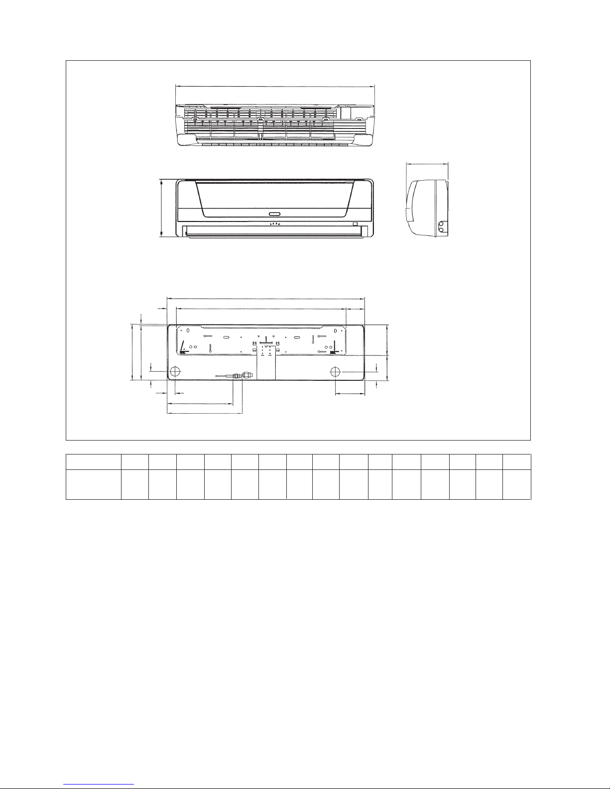
Indoor Unit (MWMXG Series)
All dimensions are in mm / (in)
Dimension
20 / 25G / GR
I
48
(1,9)
H
8
(0,3)
G
51
(2,0)
F
99
(3,9)
E
294
(11,6)
D
912
(35,9)
C
220
(8,6)
B
310
(12,2)
A
1060
(41,7)
O
160
(6,3)
N
138
(5,4)
M
160
(6,3)
L
403
(15,9)
K
354
(13,9)
J
43
(1,7)
FRONT VIEW
TOP VIEW
SIDE VIEW
INSTALLATION
PLATE
A
B
C
A
B
D
F
G
M
H
I
I
O
N
M
K
L
J
CENTER LINE
Page 4
iii
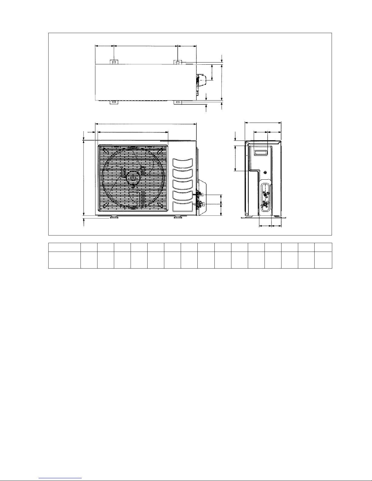
Outdoor Unit (MLCX Series)
All dimensions are in mm / (in)
Dimension A B C D E F G H I J K L M N O
10 / 15C / CR 700 521 250 485 175 36 95 93 86 68 441 130 111 15 18
(27,5) (20,5) (9,8) (19,1) (6,8) (1,4) (3,7) (3,6) (3,3) (2,6) (17,3) (5,1) (4,3) (0,5) (0,7)
3
(0,1)
B
EF
NCN
KLL
M
30
(1,2)
A
D
19
(0,7)
C
GH
I
J
O
80
(3,1)
65
(2,6)
Page 5
iv
Dimension A B C D E F G H I J K L M N O
20 / 25C / CR 855 730 328 513 182 44 93 149 101 113 603 126 164 17 47
(33,7) (28,7) (12,9) (20,2) (7,2) (1,7) (3,7) (5,9) (4,0) (4,4) (23,7) (5,0) (6,4) (0,7) (1,9)
Dimension P Q R S T
20 / 25C / CR 32 3 23 73 75
(1,3) (0,1) (0,9) (2,9) (3,0)
NOTICE
This product is subjected to Waste of Electrical and Electronic Equipment Regulations (WEE
E
Regulations). The waste product shall be separately collected by specific collection and treatment centre
.
P
lease refer to local authorithy for these centres. This is only applicable to European Union countries
.
Ce produit est soumis
à
la r
é
é
chets des
é
é
lectriques e
t
é
lectroniques (r
é
é
chet doit
ê
tre collect
é
s
é
parém
ent par un centre de collect
e
et de traitement s
p
é
cifique. Veuillez vous r
ééé
s locales pour conna
tre ces centres. Ceci
é
enne
.
Questo prodottoè soggetto alle disposizioni RAEE (Rifiuti di apparecchiature elettriche ed elettroniche)
.
à
ritirato da un centro incaricato del ritiro e smaltimento. Per conoscere il
n
ome del centro pertinente, contattare le autori
t
à
locali. Questa disposizione
è
valida solamente i paes
i
dell
U.E.
é
ctrico y Electrnico en materia d
e
ado ser
fico
de colecc
i
n
Europea
.
Dieses Produkt unterliegt den Bestimmungen zur Entsorgung von elektrischen und elektronische
n
er
tes
ü
ll bei Ihrer rtlichen
M
ü
ndiges Abfall-Amt. Dieser
Hinweis gilt nur f
nder der Europ
ischen Union
.
правиламип
о
у
тилизаци
и
отходо
в
(WEEE Regulations).
т
и
правил
а
Европейског
о
B
A
Q
R
ST
DO
KLL
CN
P
M
N
FE
C
GH
IJ
All dimensions are in mm / (in)
Page 6

1-1
English
This manual provides the procedures of installation to ensure a safe and good standard of operation for the air
conditioner unit.
Special adjustment may be necessary to suit local requirements.
Before using your air conditioner, please read this instruction manual carefully and keep it for future reference.
INSTALLATION MANUAL
INVERTER WALL MOUNTED SPLIT TYPE AIR CONDITIONER
COOLING ONLY
R22
WMX20G/MWMX020G
SLV20B/MLCV020B
R410A
5WMX10G/M5WMX010G
5SLX10C/M5LCX010C
5WMX15G/M5WMX015G
5SLX15C/M5LCX015C
5WMX20G/M5WMX020G
5SLX20C/M5LCX020C
5WMX25G/M5WMX025G
5SLX25C/M5LCX025C
Part No.: A08014078756
HEAT PUMP
R410A
5WMX10GR / M5WMX010GR
5SLX10CR / M5LCX010CR
5WMX15GR / M5WMX015GR
5SLX15CR / M5LCX015CR
5WMX20GR / M5WMX020GR
5SLX20CR / M5LCX020CR
5WMX25GR / M5WMX025GR
5SLX25CR / M5LCX025CR
IM-WMXG-0205 (1)-McQuay
Page 7

1-2
CONTENTS
Before installing the air conditioner unit, please read the following safety precautions carefully.
SAFETY PRECAUTIONS
- Outline And Dimensions page i-iv
- Safety Precautions page 2
- Installation Diagram page 3
- Installation Of The Outdoor Unit page 3
- Installation Of The Indoor Unit page 4
- Refrigerant Piping page 5
- Electrical Wiring Connection page 6
- Special Precautions When Dealing
with R410A Unit page 6
- Vacuuming and Charging page 7
- Indicator Lights page 8
- Air Conditioner Unit Operation page 9
- Operating Range page 9
- Electrostatic Filter page 10
- Auto Random Re-Start Function page 10
- Service And Maintenance page 11
- Troubleshooting page 12
! Caution
Please take note of the following important points when installing.
• Do not install the unit where leakage of flammable gas may occur.
If gas leaks and accumulates around the unit, it may cause fire ignition.
• Ensure that the drainage piping is connected properly.
If the drainage piping is not connected properly, it may cause water leakage.
• Do not overcharge the unit.
This unit is factory pre-charged. Overcharge will cause over-current or damage to the compressor.
• Ensure that the units panel is closed after service or installation.
Unsecured panels will cause the unit to operate noisily.
• Sharp edges and coil surfaces are potential locations which may cause injury hazards. Avoid from
being in contact with these places.
! Warning
• Installation and maintenance should be performed by qualified persons who are familiar with local code and
regulation, and experienced with this type of appliance.
• All field wiring must be installed in accordance with the national wiring regulation.
• Ensure that the rated voltage of the unit corresponds to that of the name plate before commencing wiring work
according to the wiring diagram.
• The unit must be GROUNDED to prevent possible hazards due to insulation failure.
• All electrical wiring must not touch the refrigerant piping, compressor or any moving parts of the fan motors.
• Confirm that the unit has been switched OFF before installing or servicing the unit.
Page 8

1-3
English
INSTALLATION DIAGRAM
Indoor Unit
Refrigerant Piping
Air Discharge
Nozzle
Air Intake
Drain Hose
Signal Receiver
Indicator
Lights
Air Intake
Grille
Back Housing
ON/OFF Switch
Front Frame
Air Filter
Outdoor Unit
Dimension A B C D
Minimum Distance, 300 1000 300 500
mm (in) (11.8) (39.4) (11.8) (19.7)
INSTALLATION OF THE OUTDOOR UNIT
The outdoor unit must be installed in such a way, so as to
prevent short circuit of the hot discharged air or obstruction to the smooth air flow. Please follow the installation
clearances shown in the figure. Select the coolest possible
place where intake air temperature is not greater than the
outside air temperature (maximum 45°C).
Installation clearances
Note: If there is any obstacle higher than 2m, or if there is
any obstruction at the upper part of the unit, please allow
more space than the figure indicated in the above table.
Condensed Water Disposal of Outdoor Unit
(Heat Pump Unit Only)
• There are 2 holes on the base of Outdoor Unit for
condensed water to flow out. Insert the drain elbow to
one of the holes.
• To install the drain elbow, first insert one portion of the
hook to the base (portion A), then pull the drain elbow
in the direction shown by the arrow while inserting the
other portion to the base. After installation, check to
ensure that the drain elbow clings to base firmly.
• If the unit is installed in a snowy and chilly area, condensed water may freeze in the base. In such case,
please remove plug at the bottom of unit to smooth the
drainage.
Obstacle
Return Air
Service Access
Obstacle
Obstacle
Return Air
Discharge Air
Obstacle
Please remove side
plate when connecting the piping and
connecting cord
PUSH & PULL UP
BASE
A
DRAIN
ELBOW
DRAIN
ELBOW
PLUG
A
B
C
D
Page 9

1-4
INSTALLATION OF THE INDOOR UNIT
The indoor unit must be installed in such a way so as to
prevent short circuit of the cool discharged air with the hot
return air. Please follow the installation clearance shown in
the figure. Do not place the indoor unit where there could
be direct sunlight shining on it. Also, this location must be
suitable for piping and drainage, and be away from doors
or windows.
Routing Of Piping
Remove the screw holding the front panel.
Maintenance &
Servicing Space
Air Flow
Direction
Higher Than
Eye Level
The refrigerant piping can be routed to the unit in a
number of ways (left or right from the back of the unit), by
using the cut-out holes on the casing of the unit (see figure).
Bend the pipes carefully to the required position in order to
align it with the holes. For the right hand and rear side out,
hold the bottom of the piping and then position it to the
required direction (see figure). The condensation drain hose
can be taped to the pipes.
Correct
1
2
3
4
5
Piping Routing
Right & Rear Side Routing
Drain hose
Fix with vinyl tape
Unit piping
50.0 mm 50.0 mm
50.0 mm
Hole With Cone Drill
Indoor Side
Outdoor Side
Mounting Installation Plate
Ensure that the wall is strong enough to withstand the weight
of the unit. Otherwise, it is necessary to reinforce the wall
with plates, beams or pillars.
Use the level gauge for horizontal mounting, and fix it with
4 suitable screws.
In case the rear piping draws out, drill a hole 65mm in diameter with a cone drill, slightly lower on the outside wall
(see figure).
Mount The Unit Onto The Installation Plate
Hook the indoor unit onto the upper portion of the
installation plate (Engage the two hooks at the rear top of
the indoor unit with the upper edge of the installation plate).
Ensure that the hooks are properly seated on the
installation plate by moving it to the left and right.
Water Drainage Piping
The indoor drain pipe must be in a downward gradient for
smooth drainage. Avoid situations that are likely to cause
water to leak.
End
Dipped
Into
Water
Water
Leaking
Water
Leaking
Water
Leaking
Wrong
Wrong
Wrong
Drain
Water Drainage
Screw position in the wall
Ø 65.0 mm Hole in the wall
1. Hook the unit onto the installation plate.
Screw position in the wall
72.0
Centre Line
Ø 65.0 mm Hole in the wall
Water
Retention
Page 10

1-5
English
Piping Length & Elevation
If the pipe is too long, both the capacity and reliability of
the unit will drop. As the number of bends increases,
resistance to the flow of refrigerant system increases, thus
lowering cooling capacity. As a result, the compressor may
become defective. Always choose the shortest path and
follow the recommendations as tabulated below:
REFRIGERANT PIPING
Outdoor Unit
Indoor Unit
Ø Tube, D A (mm)
Inch mm Imperial Rigid
1/4" 6.35 1.3 0.7
3/8" 9.52 1.6 1.0
1/2" 12.70 1.9 1.3
5/8" 15.88 2.2 1.7
3/4" 19.05 2.5 2.0
Piping Connection To The Units
• Align the center of the piping and tighten the flare nut
sufficiently with fingers.
• Finally, tighten the flare nut with the torque wrench until
the wrench clicks.
Pipe Size mm / (in) Torque Nm / (ft - lb)
6.35 (1/4) 18 (13.3)
9.53 (3/8) 42 (31.0)
12.7 (1/2) 55 (40.6)
15.88 (5/8) 65 (48.0)
19.05 (3/4) 78 (57.6)
Indoor Piping
Flare Nut
Flared Tube
Flare Joint
Spanar
Torque Wrench
Cutting Copper Tube
1/4t
Remove Burr Indoor
Copper Tube
Swaging Block
Piping Works
• Do not use contaminated or damaged copper tubing. Do
not remove plastic, rubber plugs and brass nuts from the
valves, fittings, tubings and coils until you are ready to
connect suction or liquid line into valves or fittings.
• If any brazing work is required, ensure that the nitrogen
gas is passed through coil and joints while the brazing
work is being done. This will eliminate soot formation on
the inside walls of the copper tubings.
• Cut the connection pipe with a pipe cutter.
• Remove burrs from cut edges of the pipes with remover.
Hold the end of the pipe downwards to prevent metal chips
from entering the pipe.
• Insert the flare nuts, mounted on the connection parts of
both the indoor unit and outdoor unit onto the copper pipes.
• Flare the pipe with extra length above the flaring tool as
shown in the table.
• The flared edge must be even and not cracked or scratched.
Remark: The refrigerant pre-charged in the outdoor unit
is for piping length up to 7.62 m/25 ft.
Model
Maximum length, m (ft), L
Max. elevation, m (ft), H
Max. number of (90º) bends
Liquid pipe size
Gas pipe size
10 15 20 25
12 (39) 12 (39) 15 (49) 15 (49)
5 (16.4) 5 (16.4) 8 (26.2) 8 (26.2)
10 10 10 10
1/4" 1/4" 1/4" 1/4"
3/8" 1/2" 1/2" 5/8"
Page 11

1-6
1
2
3
N
L
2
1
3
ELECTRICAL WIRING CONNECTION
Inverter Cooling / Heat Pump Unit
IMPORTANT : * The figures shown in the table are for information purpose only. They should be checked and selected
to comply with the local/national codes of regulations. This is also subject to the type of
installation and conductors used.
* If the length of the cable is more than 2m, use cable with bigger
size.
• All wires must be firmly connected.
• All wires must not touch the refrigerant piping,
compressor or any moving parts of the fan motor.
• The connecting wires between the indoor unit and the
outdoor unit must be clamped on the wire clamps as
shown in the figure.
• The power supply cord must be equivalent to H05RN-F
(245IEC57) which is the minimum requirement.
Wire Clamp
Interconnection
Cable
Power Supply
Cable
Model
Voltage range
Power supply cable size* mm
2
Number of wire
Interconnection cable size* mm
2
Number of wire
Recommended time delay fuse A
220V-240V/ 1Ph/ 50Hz +
10/15
1.5
3
1.5
4
15
20/25
2.5
3
2.5
4
20
There must be a double pole
switch with a minimum 3mm
contact gap and fuse/circuit
breaker as recommended in
the fixed installation circuit.
!
Indoor Unit
Terminal Block
Outdoor Unit
Terminal Block
Power Supply
Cable
SPECIAL PRECAUTIONS WHEN DEALING WITH R410A UNIT
R410A is a new HFC refrigerant which does not damage
the ozone layer. The working pressure of this new refrigerant is 1.6 times higher than conventional refrigerant (R22),
thus proper installation / servicing is essential.
• Never use refrigerant other than R410A in an air conditioner which designed to operate with R410A.
• POE oil is used as lubricant for R410A compressor,
which is different from the mineral oil used for R22 compressor. During installation or servicing, extra precaution must be taken not to expose the R410A system too
long to moist air. Residual POE oil in the piping and
components can absorb moisture from the air.
• To prevent mischarging, the diameter of the service port
on the flare valve is different from that of R22.
• Use tools and materials exclusively for refrigerant
R410A. Tools exclusively for R410A are manifold valve,
charging hose, pressure gauge, gas leak detector, flare
tools, torque wrench, vacuum pump and refrigerant cylinder.
• As an R410A air conditioner incurs higher pressure than
R22 units, it is essential to choose the copper pipes correctly. Never use copper pipes thinner than 0.8mm even
though they are available in the market.
• If the refrigerant gas leakage occurs during installation /
servicing, be sure to ventilate fully. If the refrigerant gas
comes into contact with fire, highly hazardous gas may
be produced.
• When installing or removing an air conditioner, do not
allow air or moisture to remain in the refrigerant cycle.
Page 12

1-7
English
VACUUMING AND CHARGING
Purging the piping and the indoor unit
Except for the outdoor unit which is pre-charged with
refrigerant, the indoor unit and the refrigerant
connection pipes must be air-purged because the air
containing moisture that remains in the refrigerant cycle may
cause malfunction of the compressor.
• Remove the caps from the valve and the service port.
• Connect the center of the charging gauge to the vacuum
pump.
• Connect the charging gauge to the service port of the
3-way valve.
• Start the vacuum pump. Evacuate for approximately
30 minutes. The evacuation time varies with different
vacuum pump capacity. Confirm that the charging gauge
needle has moved towards -760mmHg.
Caution
• If the gauge needle does not move to -760mmHg, be
sure to check for gas leaks (using the refrigerant
detector) at flare type connection of the indoor and outdoor unit and repair the leak before proceeding to the
next step.
• Close the valve of the charging gauge and stop the
vacuum pump.
• On the outdoor unit, open the suction valve (3 way) and
liquid valve (2 way) (in anti-clockwise direction) with
4mm key for hexagon sacked screw.
Service Port
Outdoor Unit 3 ways valve
Flare nut
Refrigerant Piping
Allen key
Suction
valve
Discharge
Valve
Indoor Unit
Outdoor Unit
Liquid side
Gas side
Vacuum
pump
Open
Close
Close
Close
Hi
Low
Model
10 / 15G
10 / 15GR
20G
20GR
25G
25GR
10m/32.8ft 12m/39.4ft 15m/49.2ft
35 65 –
50 90 –
35 65 110
60 110 185
90 165 280
120 220 370
Additional charge in gram (For R22 models)
Model
10 / 15G
10 / 15GR
20G
20GR
25G
25GR
10m/32.8ft 12m/39.4ft 15m/49.2ft
35 60 –
45 80 –
35 60 100
55 100 165
80 150 265
110 200 335
Additional charge in gram (For R410A models)
Additional charge
The refrigerant is pre-charged in the outdoor unit. If the
piping length is less than 7.62m (25ft), then additional charge
after vacuuming is not necessary. If the piping length is more
than 7.62m (25ft), then use the additional charge valve as
indicated in the table.
Open
Open
Suction
Valve
Discharge Valve
Indoor Unit
Outdoor Unit
Liquid side
Gas side
Check
Valve
Close
Hi
Low
Charge operation
This operation must be done by using a gas cylinder and a
precise weighing machine. The additional charge is toppedup into the outdoor unit using the suction valve via the service port.
• Remove the service port cap.
• Connect the low pressure side of the charging gauge to
the suction service port center of the cylinder tank and
close the high pressure side of the gauge. Purge the air
from the service hose.
• Start the air conditioner unit.
• Open the gas cylinder and low pressure charging valve.
• When the required refrigerant quantity is pumped into
the unit, close the low pressure side and the gas cylinder
valve.
• Disconnect the service hose from service port. Put back
the service port cap.
Page 13

1-8
IR signal receiver
When an infrared remote control operating signal has
been transmitted, the signal receiver on the indoor unit
will make a <beep> sound to confirm acceptance of the
signal transmission.
Cooling unit / Heat Pump unit
The table shows the LED indicator lights for the air conditioner unit under normal operation and fault conditions.
The LED indicator lights are located at the middle of the air
conditioner unit.
The heat pump units are equipped with an “auto” mode
sensor whereby it will provide reasonable room temperature
by switching automatically to either “cool” or “heat”
mode according to the temperature set by the user.
INDICATOR LIGHTS
LED indicator lights
IR Receiver
LED Indicator Lights for Cooling Unit / Heat Pump
Unit
Sleep Mode Cool Timer Ionizer/NTP
Inverter Unit (MWMX-G)
LED Indicator Lights : Normal Operation And Fault Conditions For Cooling / Heat Pump Unit
Normal Operation / Fault Indication Action
Cool mode –
Heat mode –
Auto mode in Cooling/Heating operation –
Timer on –
Sleep mode on –
Ionizer on –
Fan mode on –
Dry mode on –
Defrost operation –
Indoor temperature sensor loose / short Call your dealer
Coil temperature sensor loose / short Call your dealer
Outdoor temperature sensor loose / short Call your dealer
Compressor overload protection Call your dealer
IPM / PFC error Call your dealer
Outdoor total current trip / DC peak Call your dealer
Compressor overheat / Gas leak Call your dealer
Indoor fan feedback error Call your dealer
Communication error between indoor
and outdoor
Call your dealer
COOL/HEAT
(GREEN/RED)
Orange
Red
Green
ON
ON or OFF Blinking
Red
Green
Green
Green
Green
Page 14

1-9
English
OPERATING RANGE
Heat Pump Unit
Cooling unit
Temperature Ts °C / °F Th °C / °F
Minimum indoor
19.0 / 66.2 14.0 / 57.2
temperature
Maximum indoor
32.0 / 89.6 23.0 / 73.4
temperature
Minimum outdoor
19.4 / 66.9 –
temperature
Maximum outdoor
46.0 / 114.8 –
temperature
AIR CONDITIONER UNIT OPERATION
Dry mode
• When the air humidity is high, the unit can operate in
dry mode. Press <MODE> button and choose <DRY>.
• If the room temperature is 2°C/3.6°F higher than the set
temperature, the air conditioner will operate under
cooling mode until it reaches within the 2°C/3.6°F range
of difference compared to the set temperature before it
converts to dry mode.
• If the room temperature is within the 2°C/3.6°F range
of difference compared to the set temperature, it will
directly operate under dry mode.
• The unit will operate at LOW speed under dry mode.
Heat mode (for heat pump unit only)
• When the unit is switched on from cold start or
defrosting cycle, the indoor fan will start to operate only
after the coil reaches the desired temperature.
• When the set temperature is achieved, the indoor fan
will operate until the coil cannot provide anymore
additional heat.
Horizontal Air Flow Control
• For more effective air circulation, you can manually
adjust the air discharge grille to the left or right.
• During cool mode operation and dry mode operation,
do not direct the air discharge louver downwards for too
long. If operating continues in this way, condensation
may occur on the louver, thus resulting in water
drippings.
Overheating protection (for heat pump unit only)
• In case the internal and/or the external temperature is
too high, or that the filter is dirty and clogged up, the
refrigerant may be overheated. The compressor will cut
out when the condensing temperature reaches 62°C/
143.6°F.
Temperature Ts °C / °F Th °C / °F
Minimum indoor
16.0 / 60.8 –
temperature
Maximum indoor
30.0 / 86.0 –
temperature
Minimum outdoor
-8.0 / 17.6 -9.0 / 15.8
temperature
Maximum outdoor
24.0 / 75.2 18.0 / 64.4
temperature
Ts: Dry bulb temperature. Th: Wet bulb temperature.
Horizontal
Cooling
25˚C / 77˚F
Frost prevention
• When the air filter is dirty, the evaporating temperature
will decrease and eventually cause frosting.
• The LED light will blink to indicate that the filter is
dirty. If the evaporating temperature reaches -1°C/33.8°F,
the unit will trip and defrost.
Fan speed and rated cooling capacity
• The rated cooling capacity is provided at the maximum
fan speed.
• The cooling capacity is lower when the unit is operating
at MEDIUM and LOW fan speed.
Turbo function
• If higher cooling or heating is required during operation,
press “Turbo” button on the remote control to increase
the cooling or heating capacity to maximum.
• This function will operate for 15 minutes before it resume
to the actual setting.
• The fan noise may be higher if the unit operates in “Turbo”
mode.
Page 15

1-10
DUAL ACTION ELECTROSTATIC AIR PURIFYING
AND DEODORIZING FILTER MEDIA AND FILTER FRAME
ACTION 1ELECTROSTATIC AIR PURIFYING FILTER
Removes microscopic dust, smoke and small invisible
particles to keep the room air clean with pre-charged
electrostatic polypropylene filter.
ELECTROSTATIC FILTER
ACTION 2DEODORIZING FILTER
Removes unwanted smells and odors in the air and keeps
the room air fresh with activated carbon filter.
! Caution
1. The electrostatic air purifying and deodorizing filter
should be replaced once every 6 months or when the
filter changes color to brownish, whichever is sooner.
2. Used dusty filters should be disposed and shouldn't be
reused, even if it has been cleaned and washed.
3. The filter is a consumable part which you can purchase
from your air conditioner dealer.
4. Use the new filter immediately once it has been taken
out from its sealed packing. Do not unpack the new
filter too early before it is actually used as this may
decrease its deodorizing effect.
HOW TO INSTALL
Open the
front frame
grille.
Slide out the original
filters.
Slide back the original
filter.
Insert the dual action
electrostatic and
deodorizing filters
into the slot.
AUTO RANDOM RE-START FUNCTION
If there is a power cut when the unit is operating, it will automatically resume the same operating mode when the power is
restored.
! Caution
Before turning off the power supply, set the remote controller’s ON/OFF switch to the “OFF” position to prevent the
nuisance tripping of the unit.
If this is not done, the unit’s fans will start turning automatically when power resumes, posing a hazard to service
personnel or the user.
Page 16

1-11
English
SERVICE AND MAINTENANCE
Maintenance Procedures
1. Remove any dust adhering to the filter by using a vacuum cleaner or wash
in lukewarm water (below 40°C/104°F) with a neutral cleaning detergent.
2. Rinse the filter well and dry before placing it back onto the unit.
3. Do not use gasoline, volatile substances or chemicals to clean the filter.
1. Clean any dirt or dust on the grille or panel by wiping it with a soft cloth
soaked in lukewarm water (below 40°C/104°F) and a neutral detergent
solution.
2. Do not use gasoline, volatile substances or chemicals to clean the
indoor unit.
Period
At least once
every 2 weeks.
More frequently if
necessary.
At least once
every 2 weeks.
More frequently if
necessary.
Service Parts
Indoor air filter
Indoor unit
1 Off the unit.
2 Unscrew the air discharge housing.
3 Flip open the air discharge housing.
4 Clean the blower.
5 Close the air discharge housing and tighten it with screw.
! Warning
• Disconnect from the main power supply before servicing the air conditioner unit.
• DO NOT pull out the power cord when the power is ON. This may cause serious electrical shocks which may result
in fire hazards.
! Caution
Do not operate any heating apparatus too close to the air conditioner unit. This may cause the plastic
panel to melt or deform as a result of the excessive heat.
Page 17

1-12
When The Unit Is Not To Be Used For An Extended Long Period Of Time
Operate the unit for 2 hours
with the following setting.
Operating mode : cool
Temperature : 30°C/86°F
Remove the power plug.
If you are using an independent
electric circuit for your unit,
cut off the circuit.
Remove the batteries in the
remote control.
If any malfunction of the air conditioner unit is noted, immediately switch off the power supply to the unit.
Check the following fault conditions and causes for some simple troubleshooting tips.
TROUBLESHOOTING
Causes / Action
- Protection against frequent starting. Wait for 3 to 4 minutes for
the compressor to start operating.
- Power failure, or the fuse needs to be replaced.
- The power plug is disconnected.
- It is possible that your delay timer has been set incorrectly.
- If the fault persist after all these verifications, please
contact the air conditioner unit installer.
- The air filter is dirty.
- The doors or windows are open.
- The air suction and discharge are clogged.
- The regulated temperature is not high enough.
- Odours may be caused by cigarettes, smoke particles, perfume
etc. which might have adhered onto the coil.
- This is caused by air humidity after an extended long period of
operation.
- The set temperature is too low, increase the temperature setting
and operate the unit at high fan speed.
- Switch off unit and call dealer.
- Refrigerant fluid flowing into the evaporator coil.
Fault
1. The compressor does not operate 3 minutes after the air
conditioner unit is started.
2. The air conditioner unit does not operate.
3. The air flow is too low.
4. Discharge air flow has bad odour.
5. Condensation on the front air grille of the indoor unit.
6. Water flowing out from the air conditioner unit.
7. Hissing air flow sound from the air conditioner unit during
operation.
If the fault persists, please call your local dealer / serviceman.
Page 18

• In the event that there is any conflict in the interpretation of this manual and any translation of the same in any language,
the English version of this manual shall prevail.
• The manufacturer reserves the right to revise any of the specification and design contain herein at any time without prior
notification.
• En cas de désaccord sur l’interprétation de ce manuel ou une de ses traductions, la version anglaise fera autorité.
• Le fabriquant se réserve le droit de modifier à tout moment et sans préavis la conception et les caractéristiques techniques
des appareils présentés dans ce manuel.
• Im Falle einer widersprüchlichen Auslegung der vorliegenden Anleitung bzw. einer ihrer Übersetzungen gilt die Ausführung
in Englisch.
• Änderungen von Design und technischen Merkmalen der in dieser Anleitung beschriebenen Geräte bleiben dem Hersteller
jederzeit vorbehalten.
• Nel caso ci fossero conflitti nell’interpretazione di questo manuale o delle sue stesse traduzioni in altre lingue, la versione
in lingua inglese prevale.
• Il fabbricante mantiene il diritto di cambiare qualsiasi specificazione e disegno contenuti qui senza precedente notifica.
• En caso de conflicto en la interpretación de este manual, y en su traducción a cualquier idioma, prevalecerá la versión
inglesa.
• El fabricante se reserva el derecho a modificar cualquiera de las especificaciones y diseños contenidos en el presente
manual en cualquier momento y sin notificación previa.
• В случае противоречия перевода данного руководства с другими переводами одного и того же текста,
английский вариант рассматривается как приоритетный.
• Завод-изготовитель оставляет за собой право изменять характеристики и конструкцию в любое время
без предварительного уведомления.
 Loading...