

Page 1
Installation & Maintenance Data IM 447-7
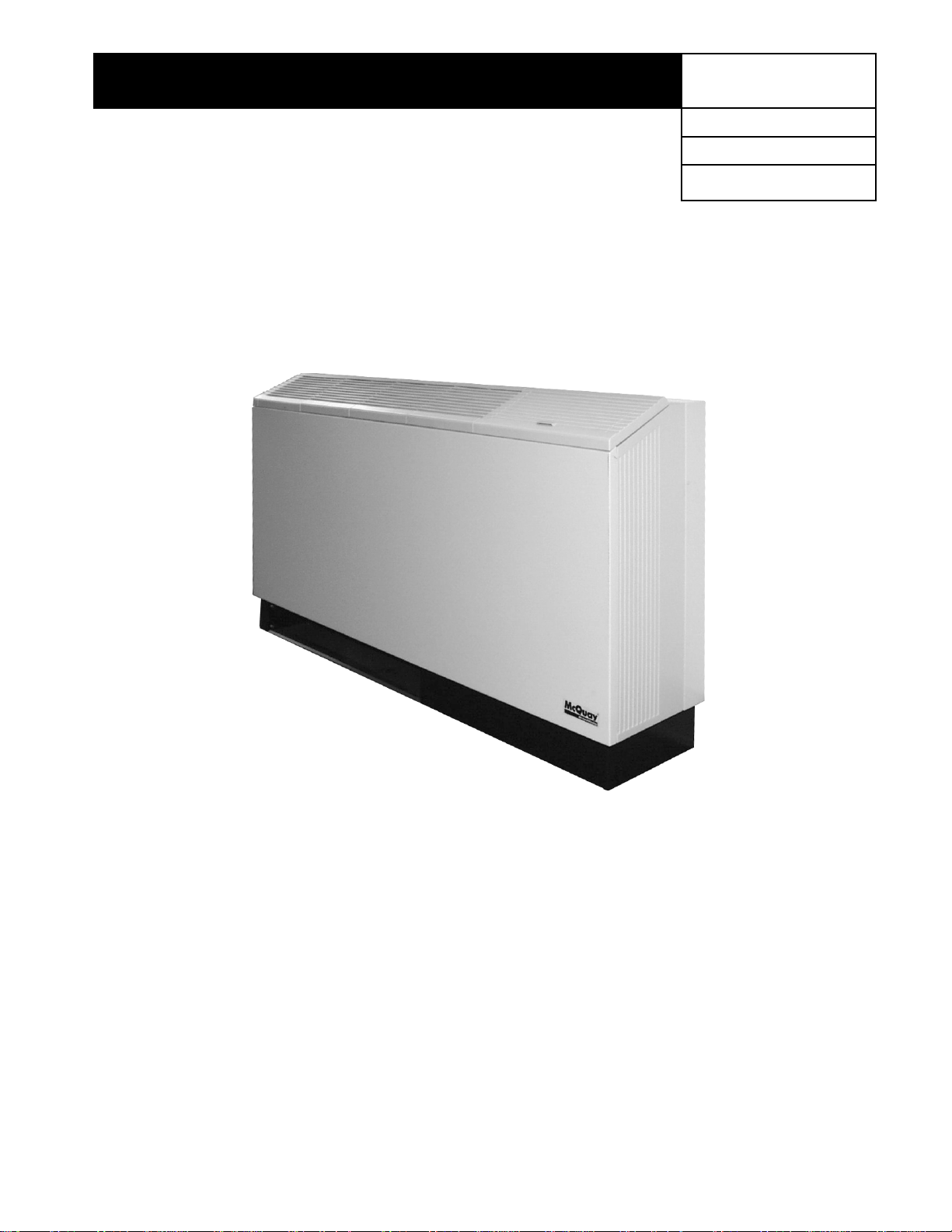
Installation & Maintenance Data
Console Water Source Heat Pump
Group: WSHP
Part Number: 107225601
Date: October 2004
Contents
Model Nomenclature . . . . . . . . . . . . . . . . . . . . . . . . . . . . . 2
Checking for Damage . . . . . . . . . . . . . . . . . . . . . . . . . . . . 3
Installation . . . . . . . . . . . . . . . . . . . . . . . . . . . . . . . . . . . . 3,4
Electrical Connections . . . . . . . . . . . . . . . . . . . . . . . . . . . 5
Cabinet Power Connections . . . . . . . . . . . . . . . . . . . . . . . 5
Water Connections . . . . . . . . . . . . . . . . . . . . . . . . . . . . . . 6
Piping . . . . . . . . . . . . . . . . . . . . . . . . . . . . . . . . . . . . . . . . 7
Cleaning & Flushing System . . . . . . . . . . . . . . . . . . . . . . . 7
Operating Limits . . . . . . . . . . . . . . . . . . . . . . . . . . . . . . . . 8
Electrical Data . . . . . . . . . . . . . . . . . . . . . . . . . . . . . . . . . . 8
©2004 McQuay International
Unit Operation . . . . . . . . . . . . . . . . . . . . . . . . . . . . . . . . . . 8
Wiring Diagrams – Mark IV/AC-Units . . . . . . . . . . . . . . 9,10
Control Options . . . . . . . . . . . . . . . . . . . . . . . . . . . . . . . . 11
Thermostats – Mark IV/AC-Units . . . . . . . . . . . . . . . . . . 12
Pump Restart Relay . . . . . . . . . . . . . . . . . . . . . . . . . . . . 13
MicroTech Control Units . . . . . . . . . . . . . . . . . . . . . . . 14,15
Field Installed Options . . . . . . . . . . . . . . . . . . . . . . . . . . 16
Optional Outside Air Damper . . . . . . . . . . . . . . . . . . . . . 18
Troubleshooting . . . . . . . . . . . . . . . . . . . . . . . . . . . . . . 18,19
Maintenance . . . . . . . . . . . . . . . . . . . . . . . . . . . . . . . . . . 19
IM-447 / Page 1
Page 2

Product Category
W = WSHP
Product Identifier
See box below
Model Nomenclature
NOTE: For illustration purposes only. Not all options available with all models.
Please consult a McQuay Sales Representative for specific availability.
McQuay WSHP Product Nomenclature
W WDA 1 009 E Z
Design Series
1 = A Design
2 = B Design
3 = C Design
4 = D Design
5 = E Design
Nominal Capacity
007 = 7,000
009 = 9,000
012 = 12,000
015 = 15,000
019 = 19,000
McQuay WSHP Product Identifiers
WDA = Flat Top Wall mtd./DDC Controls/Low Sill
WDB = Slope Top Wall mtd./DDC Controls/Low Sill
WDD = Slope Top Wall mtd./DDC Controls/Low Sill/Chassis Only
WDE = Slope Top Wall mtd./DDC Controls/Low Sill/Chassis Only
WDF = Flat Top Wall mtd./DDC Controls/High Sill
WDG = Flat Top Wall mtd./DDC Controls/High Sill/Less Board
WDH = Slope Top Wall mtd./DDC Controls/High Sill/Less Board
WDS = Slope Top Wall mtd./DDC Controls/High Sill
WLA = Slope Top Wall mtd./Mark IV/High Sill/Low Limit, NSB & Override
WLB = Flat Top Wall mtd./Mark IV/Low Sill/Low Limit, NSB & Override
WLC = Slope Top Wall mtd./Mark IV/Low Sill/Low Limit, NSB & Override
WLL = Flat Top Wall mtd./Mark IV/High Sill/Low Limit, NSB & Override
Coil Options
(None)
Voltage
A = 115-60-1
E = 208/230-60-1
J = 265-60-1
M = 230-50-1
WMA = Slope Top Wall mtd./Mark IV/Low Sill
WMB = Flat Top Wall mtd./Mark IV/Low Sill
WMC = Flat Top Wall mtd./Mark IV/High Sill/Chassis Only
WMD = Flat Top Wall mtd./Mark IV/Low Sill/Chassis Only
WME = Flat Top Wall mtd./Mark IV/High Sill/European Spec.
WMF = Flat Top Wall mtd./Mark IV/High Sill
WMG = Slope Top Wall mtd./Mark IV/High Sill/Chassis Only
WMH = Slope Top Wall mtd./Mark IV/Low Sill/Chassis Only
WMJ = Flat Top Wall mtd./Mark IV/Low Sill/European Spec.
WMK = Flat Top Wall mtd./Mark IV/High Sill/Chassis Only/European Spec.
WML = Flat Top Wall mtd./Mark IV/Low Sill/Chassis Only/European Spec.
The information in this catalog supersedes and replaces previous (bulletins) with regards to McQuay Terminal Air Conditioning products.
Illustrations cover the general appearance of McQuay products at the time of publication and McQuay reserves the right to make changes in
Page 2 / IM 447
©McQuay Incorporated 2004
design and construction at anytime without notice.
Page 3

Checking for Damage
Upon receipt of the equipment, check carton for visible
damage. Make a notation on the shipper’s delivery ticket
before signing. If there is any evidence of rough handling, the
cartons should be opened at once to check for concealed
damage. If any damage is found, notify the carrier within 48
hours to establish your claim, and request their inspection
and a report. The Warranty Claims Department should then
be contacted.
Do not stand or transport the machines on end. For storing,
each carton is marked with “up” arrows.
In the event that elevator transfer makes upended
positioning unavoidable, absolutely insure that the machine
is in the normal upright position for at least 24 hours
before operating.
Temporary storage at the jobsite must be indoors, completely
sheltered from rain, snow, etc. High or low temperatures
naturally associated with weather patterns will not harm the
conditioners. Excessively high temperatures of 140˚F (60˚C)
may deteriorate certain plastic materials and cause permanent
damage. In addition, the solid-state circuit boards may
experience operation problems.
Note: Care should be taken when handling this equipment.
Rough handling can create damage to internal electrical and
refrigeration components.
Installation
Installation and maintenance are to be performed by qualified personnel who are familiar with local codes and
regulations, and experienced with this type of equipment. Caution: Sharp edges and coil surfaces are a potential injury
hazard. Avoid contact with them.
General:
1. Units must be installed in accordance with all applicable codes.
2. To prevent damage, this equipment should not be
operated for supplementary heating and cooling during
the construction period.
3. Inspect the carton for any specific tagging numbers
indicated by McQuay International per a request from
the installing contractor. At this time, the voltage, capacity
and model should be checked against the plans.
4. Check the unit size against the plans to be sure that the
unit will be installed in the correct location.
5. Units should be kept in shipping carton until installed.
At the time the unit is to be placed in its final position –
and only then – should the carton be removed. Retain
the carton and cut away one side and bottom. Take the
remaining portion of the carton and place it over the
unit. This will insure the unit is protected from paint
spotting, dirt, dust and lint that can affect proper unit
operation, and will also prevent needless cleaning
adding to installation cost.
6. The installing contractor will find it beneficial to confer
with other contractors; i.e., plumbing, electrical, pipe
fitters, etc., before installing any conditioners.
7. Remove the front panel by removing a screw on each
side of the cabinet at the subbase.
8. All piping and electrical wiring should be flexible so
that vibrations are not transmitted to the building
structure. Ensure all electrical connections are in place
and tight.
9. Locate the unit in an area that allows easy removal or
accessibility for service personnel to perform maintenance and repair.
10. If units are placed on a concrete floor, it is recommended that the floor be free from all construction
debris that may add to the operating noise level of the
unit. It may be advisable to place a portion of rubber
matting under the unit to prevent distortion and/or
vibration.
Unit Location
1. Console water source heat pumps are designed to be
installed in a controlled environment.
2. All units are to be installed against a wall.
3. Each unit should be located on the architectural plans.
The supply, return, and condensation piping should be
located accordingly, making sure the piping will fit into
the confines of the subbase and cabinet.
Installing the Unit
1. Consult job blueprints for unit location. Clean area
where unit is to be installed, removing all construction
dirt and debris.
2. Remove unit from shipping carton and save the carton.
Remove the front panel by removing a screw on each
end of the cabinet. Lift the cabinet up, forward and off.
3. Each chassis is mounted to cabinet backwrap and
subbase assembly by six screws for shipment. Remove four screws, two on each side of the chassis at
the subbase.
4. Position cabinet backwrap and subbase against the
wall where unit is to be installed. Ensure adequate
room exists for piping and electrical connection in the
subbase by checking the connection end of the subbase.
5. Using a carpenter’s square and level, make sure unit is
level and that it is at a 90-degree angle with the wall
and floor. (Note: If the floor and wall are not at right
angles, it may be necessary to shim the subbase to
insure proper installation. McQuay International will not
accept responsibility for units that may need to be
shimmed. Poor or inadequate installation could create
noisy unit operation.)
6. The cabinet backwrap has slots on the back flange to
mount the assembly to the wall. It is the contractor’s
responsibility to select the correct fastener for each unit.
7. After securing the subbase and backwrap assembly in
place, insert the chassis if it has been removed. Next,
the electrical connection should be made.
IM-447 / Page 3
Page 4
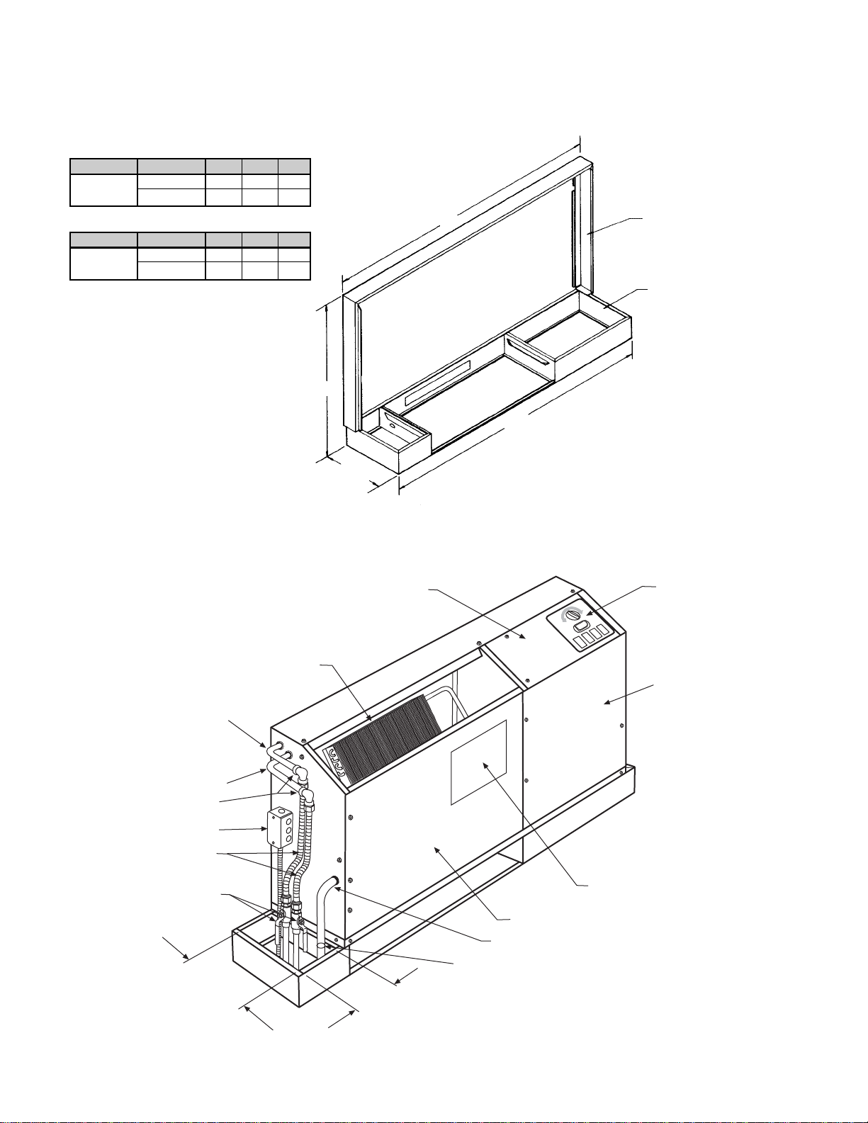
Figure 1. Cabinet backwrap &-subbase
*Total unit is 103/4" (273mm) deep. The cabinet extends beyond
the subbase
Dimensions in inches
Dimensions in mm
1
/4" (6mm) in the back and 1/2" (14mm) in the front.
Unit Type Unit Size A B C
Standard 007 – 012 46 45 25
Height 015 – 019 54 53 25
Unit Type Unit Size A B C
Standard 007 – 012 1168 1143 635
Height 015 – 019 1372 1346 635
C
10.0"*
(245mm)
A
Backwrap
Subbase
B
Figure 2. Chassis (Left-hand slope top unit shown)
Control Diagram
Air Coil
Water Return
Water Supply
All Pipe Fittings Are
To Be Field Installed
Junction Box
Flexible Hoses
Ball Valves
Electric Conduit
9.0"
(229mm)
(127mm)
5.0"
Condensate Line–14"
(356mm) Clear Vinyl
Hose Clamp
Wiring Diagram
Fan/Coil Section Access Panel
Escutcheon
Plate
Compressor/
Control Box
Access Cover
Page 4 / IM 447
Page 5
Electrical Connections
Standard Electrical Connection
Each chassis comes with a junction box mounted on the
side of the chassis and contains the field electrical connection.
Note: If electrical wiring or conduit comes through the
floor, all wires or conduit should be sealed at this point. It
will prevent any condensation or water leakage that may
occur due to lack of preventive maintenance. Each unit has
an internal condensate trap but will require cleaning.
Note: We suggest wiring coming through the wall should
also be sealed to stop cold air infiltration through the wall
cavity which could affect unit thermostat operation.
Remove the junction box cover, selecting the proper
knockout and remove it. Install a strain relief and pass the
wires through the strain relief into the junction box making
the connection and reinstall the junction box cover.
Note: Check the local code concerning correct electrical connection.
Cord & plug electrical connection (field installed)
Cord connected equipment comes with a box and appropriate
voltage receptacle. However, a disconnect switch and fuses
can also be provided in the box. As an option, the box
comes factory mounted on the backwrap and is ready to be
field wired to the incoming power. The box is mounted on
the same side as the piping.
It is the responsibility of the installing contractor to make
the proper electrical connection to the electrical box, using
the same method as described in the standard electrical
connection. See Figures 3 and 4.
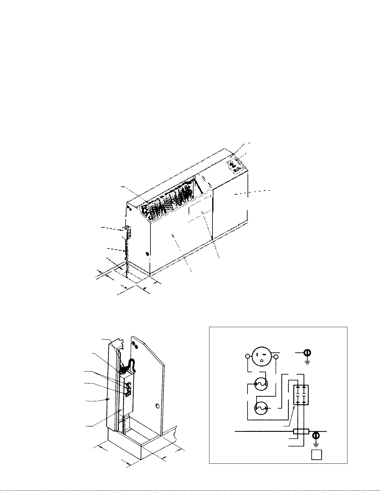
Figure 3. Standard electrical connection – Junction box
Air Coil
Junction Box
Electrical Conduit
Floor
1.0"*
(25mm)
*1.0" (25mm) from inside
surface of wall
9.0"
(229mm)
5.0"
(127mm)
Figure 4. Cord & Plug Connection (Field Installed)
Power Cord
Receptacle Plug
Control Box
Escutcheon Plate
Compressor Cover
Wiring Diagram
Fan Motor Cover
Cabinet Power Connection
(Field Installed)
Receptacle, Fuses & Disconnect Switch
(Requires plug cord on chassis.)
RECEPTACLE
GR/YE
Fuse Holder
Switch
Backwrap
Fuse Disconnect Box
10.0"
(254mm)
5.00"
(127mm)
PK
Fuse
WH
Disconnect Switch
BK
PK
WH
BK
Fuse
BK
WH or RD
Fused Disconnect Box
Wire Diagram 61408101
REV
0
IM-447 / Page 5
Page 6
Water Connections
All piping connections should be made using good plumbing
practices and in accordance with any and all local codes
that may apply. Note: It will be helpful to read the “Piping”
section on page eight.
Unit Piping Connection
Each heat pump is supplied with extended copper tubing on
the water-to-refrigerant coil and
connections are for both the supply and return water connections.
Note: Valves – Shut off Combination Balancing Valves,
Hoses – Supply Return, Condensate Drain Hose and 90°
Elbows are all factory available as accessories, (to be
mounted in the field by others).
1
/2" (12.7mm) OD tubing. The
Shutoff/Balancing Valve
Each heat pump requires a shutoff valve on both the supply
and return lines for easy serviceability and removal if it
becomes necessary.
We suggest using our combination shutoff/balancing
valves installed in the field between the contractor’s piping
and the heat pump unit. The valve installed on the return line
acts as a balancing valve to adjust the proper water flow.
Each shutoff/balancing valve has
1
/2" FPT ⳯ 1/2" FPT
threaded connections.
Suggested Hose Kit Installation
Field installed piping can be brought up from the floor or
through the wall. Note: Make sure the pipes fit the confines
of the piping compartment of the heat pump unit. See Figure 5.
Attach the field installed combination shut/off balancing
valve to the building water supply and return piping. Next
add the female pipe adapter connection to unit supply and
return coil connection by sweating them in place using silver
solder.
Next, using the specified hose kit, screw the fixed end
into the shut-off/balancing valve. Remove the
1
/2" adapter
from the other end of the hose. Insert the adapter into the
female fitting. Using two crescent wrenches, one to hold the pipe
connection and the second to tighten the adapter, insert the
swivel end of the hose on the adapter and tighten. This
completes the hose connection to standard heat pump equipment.
Adding Motorized & Valve Assemblies
All console water source heat pumps can be field installed
with a motorized valve. All valves are mounted on the return
line of each unit. All valve assemblies terminate with
1
/2"-NPT threaded connections and will also accommodate factory supplied hose kits. When installing the hose
kits on valve assemblies, use the same method as outlined
in “Suggested Hose Kit Installation” above.
Note: All plumbing connections are made the same way
whether or not the unit has valve packages. Whether or not
you utilize our hose kits and shutoff/balancing valve all
piping connections will have to conform with all local piping
and building codes. The ability to remove the unit in order to
perform repairs is imperative.
Condensate Hose Connection
Each unit is supplied with a 3/4" (19mm) I.D. clear vinyl
condensate hose internally trapped within the chassis. The
hose extends 14" (356mm) out of the chassis within the
piping compartment to reach the floor or the back wall.
Field condensate piping must enter within the confines of
the cabinet (back wall or floor) similar to the supply and
return piping. Slide the vinyl hose over the condensate pipe
and clamp it.
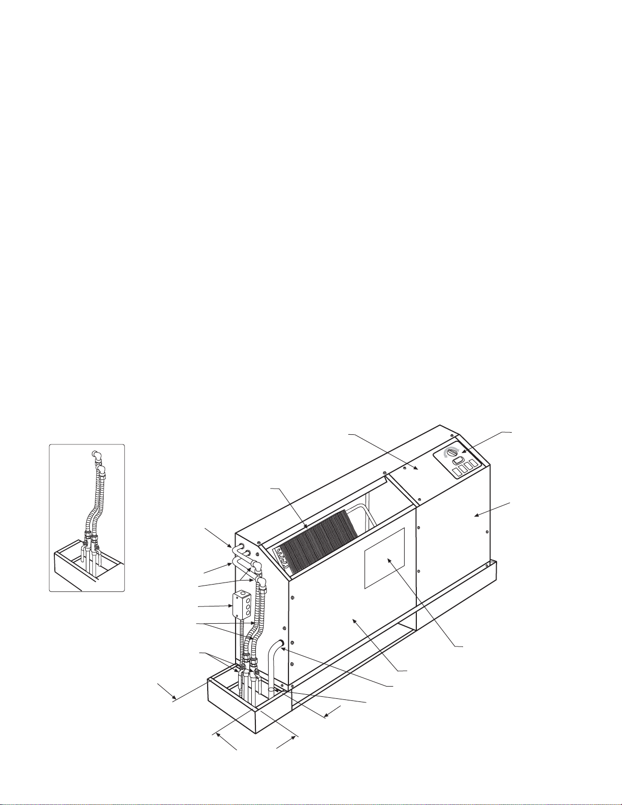
NOTE: Valves,
(shut-off combination
balancing valves),
Hoses, (supply and
return, condensate
drain hose), also 90°
elbows are all factory
available as accessories, to be mounted
in the field by others.
Water Return
Water Supply
All Pipe Fittings Are
To Be Field Installed
Junction Box
Flexible Hoses
Ball Valves
9.0"
(229mm)
Air Coil
Control Box
5.0"
(127mm)
Escutcheon
Plate
Compressor/Control
Box Access Cover
Wiring Diagram
Fan/Coil Section Access Panel
Condensate Line–14" (356mm) Clear Vinyl
Hose Clamp
Page 6 / IM 447
Page 7

Piping
1. All units are recommended to be connected to supply
and return piping in a two-pipe reverse return configuration.
A reverse return system is inherently self-balancing and
requires only trim balancing where multiple quantities of
units with different flow and pressure drop characteristics
are connected to the same loop. A simple way to check
for proper water balance is to take a differential temperature
reading across the water connections when in the
cooling mode. To insure proper water flow, the differential
should be 10˚F to 14˚F (-5˚C to -8˚C).
A direct return system may also be made to work
acceptably, but proper water flow balancing is more
difficult to achieve and maintain.
2. The piping can be steel, copper or PVC, but must
comply with local codes.
3. Supply and return runouts are usually connected to the
unit by short lengths of high pressure flexible hose
which are sound attenuators for both unit operating
noise and hydraulic pumping noise. Note: When using
the flex hose connections you must add a 90° elbow
kit, for making the connection. This elbow is sweat on
one end – female 1/2” FPT on the other end. McQuay
Part No. 106066402. One end of the hose should have
a swivel fitting to facilitate removal for service. Hard
piping can also be brought directly to the unit, although it is not recommended since additional noise
may be generated. See Figure 5 for typical piping
setup.
4. Some flexible hose threaded fittings are supplied with
sealant compound. If not, apply Teflon tape to assure a
tight seal.
5. Supply and return shutoff valves are required at each
conditioner. The return valve is used for balancing and
should have a “memory stop” so that it can always be
closed off, but can only be re-opened to the proper
position for the flow required.
6. No unit should be connected to the supply and return
piping until the water system has been cleaned and
flushed completely. After the cleaning and flushing has
taken place, the initial connection should have all valves
wide open in preparation for water system flushing.
7. Condensate piping can be steel, copper, or PVC. Each
unit is supplied with a clear vinyl condensate hose.
8. Units are internally trapped. Copper or PVC condensate
lines can be used. A means of disconnection must be
furnished to facilitate chassis removal.
9. No point of the drain system may be above the drain
pan of any unit.
10. Automatic flow control devices must not be installed
prior to system cleaning and flushing.
11. A high point of the piping system must be vented.
12. Check local code for the need for electric fittings.
Cleaning and Flushing System
1. Prior to first operation of any conditioner, the water
circulating system must be cleaned and flushed of all
construction dirt and debris.
If the conditioners are equipped with water shutoff
valves, either electric or pressure operated, the supply
and return runouts must be connected together at each
conditioner location. This will prevent the introduction of
dirt into the unit. Additionally, pressure operated valves
only open when the compressor is operating.
Figure 6.
Temporary Connection for Flushing System Piping
Swivel
Adapter
1
/2 MPT x 37
Flare JIC
Supply
Valve
2. The system should be filled at the city water makeup
connection with all air vents open. After filling, vents
should be closed.
The contractor should start main circulator with
pressure reducing valve makeup open. Vents should be
checked in sequence to bleed off any trapped air to
assure circulation through all components of the system.
Power to the heat rejector unit should be off, and
the supplementary heat control set at 80˚F (27˚C).
While circulating water, the contractor should
check and repair any leaks in the piping. Drains at the
lowest point(s) in the system should be opened for
initial flush and blowdown, making sure city water fill
1
/2" (13mm)
I.D. Hose
1
/2" (13mm) MPT
Steel Fitting
Return Valve
Floor Line
valves are set to make up water at the same rate.
Check the pressure gauge at pump suction, and
manually adjust the makeup to hold the same positive
steady pressure, both before and after opening the
drain valves. Flush should continue for at least two
hours, or longer if required, to see clear, clean drain water.
3. Supplemental heater and circulator pump should be shut
off. All drains and vents should be opened to completely
drain down the system. Short circuited supply and return
runouts should now be connected to the conditioner
supply and return connections. Teflon tape is recommended versus pipe dope for pipe thread connections.
Use no sealers at the swivel flare connections of hoses.
4. Trisodium phosphate was formerly recommended as a
cleaning agent during flushing. However, many states
and localities ban the introduction of phosphates into
their sewage systems. The current recommendation is
to simply flush longer with 80˚F (27˚C) water.
5. Refill the system with clean water. Test and treat as
required to leave the water slightly alkaline (pH 7.5 to
8.5). The specified percentage of antifreeze may also
be added at this time. Use commercial grade anti-
freeze designed for HVAC systems only. Do not use
automotive grade antifreeze.
6. Set the system control and alarm panel heat add
setpoint to 70˚F (21˚C) and heat rejection setpoint to
85˚F (29˚C). Supply power to all motors and start the
circulating pumps. After full flow has been established
through all components, including the heat rejector
(regardless of season), and air vented and loop
temperatures stabilized, each of the conditioners will
be ready for check, test, and start-up and for air and
water balancing.
7. It is not McQuay International’s policy to make recommendations on water treatment. The general contractor
or owner should contact a local water treatment company
regarding water treatment. However, this topic is critical
and care should be taken to make sure it is done properly
to prevent problems related to flow. A fouled closed loop
water system will lead to premature component failure.
IM-447 / Page 7
Page 8

Operating Limits
Environment
This equipment is designed for indoor installation only.
Sheltered locations such as attics, garages, etc., generally
will not provide sufficient protection against extremes in
temperature and/or humidity, and equipment performance,
reliability, and service may be adversely affected.
Additional Information
Units are designed to start and operate with entering air at
40˚F (4˚C), with entering water at 70˚F (21˚C), with both air
and water at the flow rates used in the ARI-Standard 320-86
rating test, for initial start-up in winter.
Note: This is not a normal or continuous condition. It is
assumed that such a start-up is for the purpose of bringing
the building space to occupancy temperature.
Electrical Data
Air and Water Limits
Cooling Heating
Min. Ent. Air ➀ ➁ 65˚F (18˚C) 55˚F (14˚C)
Normal Ent. Air. db/wb 80/67˚F (27/19˚C) 70˚F (21˚C)
Max. Ent. Air ➀ ➁ 90˚F (32˚C) 80˚F (27˚C)
Water Enthalpy
Cooling Heating
Min. Ent. Air ➀ ➁ 60˚F (16˚C) 55˚F (14˚C)
Normal Ent. Air. db/wb 85˚F (29˚C) 70˚F (21˚C)
Max. Ent. Air ➀ ➁ 110˚F (43˚C) 90˚F (32˚C)
➀ At ARI flow rate.
➁ Maximum and minimum values may not be combined. If one value is
at maximum or minimum, the other two conditions may not exceed
the normal condition for standard units.
General
1. Be sure the available power is the same voltage and
phase as that shown on the unit serial plate. Line and
voltage wiring must be done in accordance with
local codes or the National Electrical Code, whichever is applicable.
2. Apply correct line voltage to the unit. A disconnect
switch near the unit is required by code. Power to the
unit must be sized correctly and have dual element
(Class RK5) fuses or HACR circuit breaker for branch
circuit overcurrent protection. See the nameplate for
correct ratings.
Unit Operation
General
Note: At start-up of unit, ensure that temperature, flow rate
and voltage are within specified limits required for proper
unit operation. Each unit has its own control or remote
control, utilizing an internal thermostat (unit mounted) and
touch-pad selector switch or a wall mounted thermostat
(remote control units).
Mark IV/AC-Control Units
Each unit has a Mark IV/AC version printed circuit board. Its
control is available in unit mounted or remote wall thermostat.
The low voltage output from the low voltage terminal strip
on the control board is always 24 volts AC. Terminals F and
V on the low voltage terminal strip supply 24 volts
DC-power.
Continuous Fan: Units are factory wired for continuous
operation. When power is applied and the start switch is
depressed, the fan will run.
Cooling or Heating – Auto Operation: Rotate the thermostat
knob to either warmer or cooler. Select fan speed. Depress
the start button. Unit will start within 0 to 32 seconds.
Lockout Circuit: Each unit has its own lockout circuit to
lock out compressor operation when an abnormal condition
should appear. During unit operation, the compressor will be
automatically turned off due to one of the two safety
openings. High pressure is set at 400 psi (2760 kPa) and low
temperature switch is set at 28˚F (-2˚C). Condensate overflow and brownout protection are also included.
3. All 208-230V single phase units are factory wired for 208
volt operation unless specified for 230 volts.
Operating Voltages:
115/60/1 . . . . . . . . . . . . . . . 104 volts min.; 127 volts max.
208-230/60/1 . . . . . . . . . . . 197 volts min.; 253 volts max.
265/60/1 . . . . . . . . . . . . . . . 238 volts min.; 292 volts max.
230/50/1 . . . . . . . . . . . . . . . 197 volts min.; 253 volts max.
Note: Voltages listed are to show voltage range. However, units operating
with overvoltage or undervoltage for extended periods of time will experience
premature component failure.
Cooling or Heating – Manual Operation: Rotate the
thermostat knob to either warmer or cooler. Select fan
speed, depress the heat or cool button, and unit will start
within 0 to 32 seconds.
The Mark IV/AC-circuit board system has built-in features
such as random start, compressor time delay, night setback,
load shed, shutdown, condensate overflow protection, defrost
cycle, brownout, and LED/fault outputs. Figure 7 shows the
LED and fault output sequences. The 24 volt low voltage
terminal strip is set so R-G energizes the fan. R-Y1 energizes
the fan and compressor and reversing valve for heating
operation.
The reversing valve is set up to be energized in the
heating mode. The circuit board has a fan interlock circuit to
energize the fan whenever the compressor is on.
The Mark IV/AC control board has a lockout circuit to
stop compressor operation if any one of its safeties opens
(high pressure or low temperature). If the low temperature
thermostat opens, the unit will go into the cooling mode for
60 seconds to defrost any slush in the water-to-refrigerant
heat exchanger. After 60 seconds, the compressor is locked
out. If the condensate sensor detects a filled drain pan, the
compressor operation will be suspended only in the cooling
mode. The unit is reset by opening and closing the disconnect
switch on the main power supply to the unit in the event the
unit compressor operation has been suspended due to low
temperature (freezestat) switch, or high pressure switch.
The Mark IV/AC control circuit has a fault output signal to
an LED on a wall thermostat. Figure 7, Page 9, shows in which
function the fault output is “on” (sending a signal to the LED).
Page 8 / IM 447
Page 9

Figure 7.
Indication
Yellow Green Red Output
LED’s
Normal Mode Off On Off Off
High Pressure Fault Off Off Flash On
Low Temperature Fault* Flash Off Off On
Condensate Overflow On Dim Off On
Brown-out Off Flash Off On
Load Shed Off Off On Off
Unoccupied Mode On On Off Off
Unit Shutdown Off Flash Off On
Note: It will require removal of the front panel and control box cover in order
to view the PC board.
*In heating mode only.
Fault
Typical Wiring Diagrams for
Units with Mark IV/AC Controls
60 Hertz Mark IV MCO Boilerless Constant Fan
Component Layout
1. Tap-Touch Switch
2. Thermostat
3. Terminal Block
4. PC Board
5. Transformer
6. Boilerless Relay
7. Shutdown Relay
8. Auxiliary Relay
9. Heater Relay
10. Water Reg Valve Relay
11. Low Limit Thermostat
12. Night Setback Thermostat
13. Override Switch
14. Terminal Board 1
15. Terminal Board 2
16. Stop/Start Switch
17. Standby Electric Heat Switch
18. Boilerless Fan Relay
>> Plug Connection
TB Terminal Block
ACO Automatic Change Over
MCO Manual Change Over
BR Boilerless Relay
HR Heater Relay
55
6
4
11
Notes
1. Terminal block on PC board
provides 24 VAC at terminals
C and R. All other terminals are
24 VDC output.
2. All temperature and pressure
switches are normally closed.
3. Component layout is typical,
some components shown may
not be used.
4. Field supplied relays installed
on the unit terminals W1, W2,
Y1, Y2 and G may introduce
electrical noise. Never install
relay coils in series with the
inputs.
9
10
RD (009)
1
16
13
2
18
3
12
8
7
BL
(012, 019)
BL6
(009, 012, 019)
BL7
(009, 012, 019)
BL70
14
15
17
OR
11
L1
BK
OR13
RD (007, 012, 015)
OR (019) BL(009)
BK (009, 012, 019)
RD1
RD1
(007, 015)
BFR
BL70
RD8
HI
L1
OR4
MCO Thermostat
TB
HR
BL (007, 015)
BK1
BK1
BL7
RD9
(009)
LO Temp
BK2
HI Press
BR
Stop/Start Switch
RD8
LO
BK RD
BL1
2
1
3
(Not used on all sizes)
WH3
Condensate
BK3
OR12
BR
BK2
BL2
MCO
4-Button
Switch
C
W
L2 L3
OR1
Optional Cordset
Switch
BK10
WH1
Compressor
Fan
Motor
Transformer
WH 115V
RD 208V
OR 230V
BR 265V
BL
OR4
Sensor
Common
Mark IV
PC Board
RD3
BK3
WH2
BR1
HP HP LT LT COF
W
OG
2
WH1
OR15
BR
BR5
RD
H
Ribbed Lead
Limit
Heater
WH2
R
S
WH3
WH
BR
Capacitor
BR
24VAC
Splice Connector
L1
Fan
RV RV V C
W
Y
FELUAPV C
1
1
GR9
BL9
2
1
BR
3
Standby Electric
Heat Switch
RD
Boilerless
Thermostat
BL3 BL2 BL1OR3OR2OR1RD4
BR1 BR3
Capacitor
BR2 BR2
GN/YE
BK
YE
BL70
GN/YE
(Heat Pump Only)
C
o
m
Valve Solenoid
p
BK11
R
BK4
BK5
WH4
HR
R
OR9
OR9
BL10
BL5
BL10
BR
BFR
BL9
GY9
WH9
BL11WH5
Terminal Board 2
BK
BR
IM-447 / Page 9
RD 208/230V
WH 115/265V
Reversing
S
BK12
OR14
BR4
BL5
BR4
OR9
Common
L2
TB
OR2
BR
C
P
U
L
E
Page 10

Typical Wiring Diagrams for
Units with Mark IV/AC Controls
50 Hertz Mark IV MCO Boilerless Constant Fan
Component Layout
1. Tap-Touch Switch
2. Thermostat
3. Terminal Block
4. PC Board
5. Transformer
6. Boilerless Relay
7. Shutdown Relay
8. Auxiliary Relay
9. Heater Relay
10. Water Reg Valve Relay
11. Low Limit Thermostat
12. Night Setback Thermostat
13. Override Switch
14. Terminal Board 1
15. Terminal Board 2
16. Stop/Start Switch
17. Standby Electric Heat Switch
>> Plug Connection
TB Terminal Block
ACO Automatic Change Over
MCO Manual Change Over
BR Boilerless Relay
HR Heater Relay
10
55
6
4
11
Notes
1. Terminal block on PC board
provides 24 VAC at terminals
C and R. All other terminals are
24 VDC output.
2. All temperature and pressure
switches are normally closed.
3. Component layout is typical,
some components shown may
not be used.
4. Field supplied relays installed
on the unit terminals W1, W2,
Y1, Y2 and G may introduce
electrical noise. Never install
relay coils in series with the
inputs.
RD (013)
OR (016)
RD1 BK1
RD1 BK1
9
BL (013)
BK (016)
7
Fan
Motor
(size
013-016)
GN/YE
1
16
13
2
3
12
8
WH
Optional Cordset
Common
Reversing
S
BK12
BR
OR14
Solenoid
BR4
BR4
OR9
BR
L2
BL 230V 50 Hz
TB
OR2
Valv e
BR
C
P
U
L
E
BL5
L1
BK
TB
OR13
HR
GN/YE
WH1
GN/YE
Resistor
(size 004-010 only)
BR
Cap
BR
RD1
RD
(008)
RD1
RD1
RD1
(004-006)
14
15
17
OR
11
BK1
BK1
BK1
BK1
BK1
BK1
(008-010)
BL70
BK1
HI
L1
OR4
BK
LO Temp
BK2
HI Press
BR
OR11
WH1
Stop/Start Switch
RD1
LO
BK RD
BL1
2
1
3
Condensate
BK3
OR12
BR
BK2
BL2
4-Button
Switch
C
W
L2 L3
OR1
WH3
Sensor
MCO
OR4
BK3
WH2
BR1
H
MCO Thermostat
Compressor
Fan
Motor
(size
004-010)
OR
Common
Mark IV
PC Board
RD3
HP HP LT LT COF
OG
RD
Ribbed Lead
Limit
Switch
Heater
(Not used on all sizes)
R
S
BR
Capacitor
BR
Transformer
24VAC
BL
Splice Connector
Fan
W
W
Y
FELUAPV C
2
1
1
OR15
BR
BR5
BR
Standby Electric
Heat Switch
RD
BK10
WH2
WH3
WH
YE
L1
RV RV V C
GR9
BL9
2
1
3
BL3 BL2 BL1OR3OR2OR1RD4
BR1 BR3
Capacitor
BR2 BR2
BK
GN/YE
BL70
GN/YE
C
o
m
p
R
BK4
WH4
R
OR9
GY9
BK
Boilerless
Thermostat
(Heat Pump Only)
BK11
BR
BK5
HR
OR9
WH9
Terminal Board 2
WH5
BR
Page 10 / IM 447
Page 11

Motorized Valve & Relay for Unit Sizes 007 to 019
Wired as shown below the motorized valve will open on a call
for compressor operation. Valves for unit sizes 007 to 019 are
1
⁄2˝ power-open spring-return. Other thermostat combinations may be used. Valve and auxiliary relay are purchased
separately.
Motorized Valve Relay (P/N 859004354)
(P/N Valve N/O 106071401) (P/N Valve N/C 106071301)
Note: The wiring shown below can only be used when the “P”
terminal is not being used as a pump restart signal to other
equipment. If the “P” terminal must be used as a pump restart signal
to other equipment, then wire the auxiliary relay’s yellow wire to
“Y1”, white wire to “W1”, and orange wire to “C”, then the valve will
open on a call for occupied heating or cooling from the thermostat.
BL6
GN7
Normally Open Valve
Pins-Female
Valve
Elbow
Water Tube Extension
Conduit, Fitting Bushing
Plug (1) required
Use Upper
Knockout
Water Flow
Normally Closed Valve
Pins-Female
Valve
Plug (1) required
Conduit, Fitting
Bushing
Conduit
Motorized
Valve
Control Options on Mark IV/AC Units
Auxilliary Relay (P/N 106059701)
WSHP Mark IV/AC Board Low Voltage Terminal Strip
Operation: In this example
the auxiliary relay contacts
can be used to indicate a
fault condition. With the
auxiliary relay connected
as shown, the normally
open contacts will close
during a fault condition.
The auxiliary relay is designed to interface external equipment
with the Mark IV/AC board. The auxiliary relay has been provided with the components necessary to protect from electrical
damage that may occur to the Mark IV/AC board when using
standard off-the-self relays. The auxiliary relay can be used to
provide fault signals, unit operation signals, or to provide a
means for remote equipment to control the Mark IV/AC board.
The orange, yellow, and white connections are short flying leads
pre-attached to the board. The diagrams shown are some
connection examples.
BL6
BL9
BL8
PC Board
Terminal Strip
Motorized Valve
Control Relay
OR
YE
WH
Notes:
1. Use soft solder process on water tubing outside of chassis.
2. Route wires along with power leads.
3. Left hand installation shown - right hand installation is “mirror”
opposite.
4. Motorized valve (511) to be parallel to the end panel.
5. Copper to be washed prior to soldering.
6. Route conduit so it does not interfere with manual operation of
motorized valve.
BL9
BL8
GN7
6 3 1
Receptical
WSHP Mark IV/AC Board Low Voltage Terminal Strip
Operation: In this example
the auxiliary relay contacts
can be used to signal
WSHP fan operation to
another device. In this
example when the
thermostat energizes the
“G” terminal the auxiliary
relay normally open
contacts will close.
Programmable Electronic Thermostat
WSHP Mark IV/AC Board Low Voltage Terminal Strip
Thermostat Terminals
WSHP Mark IV/AC Board Low Voltage Terminal Strip
Operation: In this example
the auxiliary relay is used
to interface other control
devices to the Mark IV/AC
board. Using the Orange (-)
and White (+) wires, and
24vac or 24vdc, another
device could be used to
start and stop the WSHP
heating sequence.
P/N 105570901
Includes Thermostat and Wall Plate
(Honeywell P/N T8624D2111)
IM-447 / Page 11
Page 12

Thermostat Connection Diagrams
Mark IV/AC Units – Unit Sizes 007 to 060
Manual Changeover Thermostat (P/N 106069001)
WSHP Mark IV/AC Board Low Voltage Terminal Strip
P/N 106069001
Includes Thermostat and Subbase
(Honeywell P/N T834C2416)
Thermostat Terminals
Standard Automatic & Manual Changeover Thermostat (P/N 105570701)
WSHP Mark IV/AC Board Low Voltage Terminal Strip
Thermostat Terminals
Fan Switch: Auto / On
System Switch: Heat / Off / Cool
P/N 105570701
Includes Thermostat and Subbase
(Honeywell P/N’s T874A1598 and Q674E1460)
Fan Switch: Auto / On
System Switch: Off / Heat / Auto / Cool
Deluxe Automatic Changeover Thermostat (P/N 105571003)
WSHP Mark IV/AC Board Low Voltage Terminal Strip
P/N 105571003
Includes Thermostat and Subbase
(Honeywell P/N’s T874C1869 and Q674C1579)
Thermostat Terminals
Note: Thermostat provides a fixed 13°F differential between W1 and W2.
Fan Switch: Auto / On / Tenant Override
System Switch: Off / Auto
Non-Programmable Electronic Thermostat (P/N 105570801)
WSHP Mark IV/AC Board Low Voltage Terminal Strip
Operation: The units Mark IV/AC board
will be in the occupied mode,
monitoring terminals W1 and Y1 and
ignoring terminal W2, when the time
clock contacts are open. The Mark IV/
AC board will be in the unoccupied
mode, monitoring terminal W2 and
ignoring terminals W1 and Y1, when the
time clock contacts are closed. No
cooling is allowed during the
unoccupied mode. The tenant override
feature of the thermostat allows the
occupant to force a 2-hour override of
unoccupied mode. During this override
period the W1 and Y1 terminals are
monitored and the W2 terminal is
ignored (same as occupied).
Page 12 / IM 447
P/N 105570801
Includes Thermostat and Wall Plate
(Honeywell P/N T8524D1064)
Thermostat Terminals
Page 13

Pump Restart Relay Kit P/N 061419001
Used as an option with the Mark IV/AC board, the pump
restart relay kit provides a means to alert the loop water
controller that water flow is required by a WSHP so that the
system pump can be started. This option is typically used in
installations where the pump may be shut off when there is
no need for water flow (i.e. temperature OK, etc.). Typically
only one pump restart relay kit is required per installation as
up to 200 Mark IV/AC boards can be “daisy-chained” together.
The Mark IV/AC “P” terminal is used to determine WSHP
compressor operation. Wired as shown below, when compressor operation is required, the Mark IV/AC “P” terminal
Wiring when Installed within the LWC Panel
will change state causing a contact closure between terminal
58 and 64 signaling the loop water control (LWC) panel to
restart the loop pump if Off.
The pump restart relay kit is typically mounted within one
WSHP or within the LWC panel, whichever is more convenient, diagrams are provided below for each location. To
install the relay, remove the cover on the double-faced tape
provided on the relay and attach the relay either to the inside
of the LWC panel (adjacent to circuit breaker CB1 and
terminal block TB3) or in the WSHP control box (in a convenient location), then wire as shown below.
Wiring when Installed within a WSHP Control Box
WSHP Mark IV/AC Board Low Voltage Terminal Strip
Pump
Restart
Relay
Daisy chain to other
Mark IV/AC board “P”
and “C” terminals
Loop
Water
Controller
Terminals
IM-447 / Page 13
Page 14

Up to 3 units (P/N 056794201)
WSHP Mark IV/AC Board Low Voltage Terminal Strip
TB3
Multiple
Unit Control
Panel
TB4
TB2
TB1
WSHP Mark IV/AC Board Low Voltage Terminal Strip
WSHP Mark IV/AC Board Low Voltage Terminal Strip
P/N 105570801
Includes Thermostat and Wall Plate
(Honeywell P/N T8524D1064)
Up to 2 units (P/N 106059801)
WSHP Mark IV/AC Board Low Voltage Terminal Strip
OW2GW1Y1 F E L U A P V R C
Multiple Unit
Control
Panel
GWY CL
GW1Y1R Rc C
Thermostat Terminals
R
Y
G
W
L
WSHP Mark IV/AC Board Low Voltage Terminal Strip
OW2GW1Y1 F E L U A P V R C
P/N 105570801
Includes Thermostat and Wall Plate
(Honeywell P/N T8524D1064)
Multiple Unit Control
This multiple unit control board is an accessory used when you
need to control up to 3-units from a single thermostat. The
board is typically mounted in the unit control box closest to the
thermostat. A maximum of 2 boards may be used together if up
to 6-units must be connected and controlled from a single
thermostat.
This version of the board uses VAC relays and should not be
used in combination with any other accessories or equipment
that require VDC connections to the “G”, “W1”, or “Y1” terminals (i.e. Boilerless System Kit).
The multiple unit control board provides the components necessary to protect the Mark IV/AC board from electrical damage
that may occur when using standard off-the-self relays.
Do not use the unoccupied (U-terminal) feature with the multiple
unit control board.
This multiple unit control board is an accessory used when you
need to control up to 2-units from a single thermostat. The
board is typically mounted in the unit control box closest to the
thermostat. The “G”, “W”, “Y”, “C”, and “L” connections are
short flying leads pre-attached to the board. A maximum of 3
boards may be used together if up to 4-units must be connected
and controlled from a single thermostat.
This version of the board uses VDC relays and should not be
used in combination with any other accessories or equipment
that require VAC connections to the “G”, “W1”, or “Y1” terminals
(i.e. Boilerless System Kit). Do not use the unoccupied (Uterminal) feature with the multiple unit control board.
The multiple unit control board provides the components necessary to protect the Mark IV/AC board from electrical damage
that may occur when using standard off-the-self relays.
The multiple unit control feature is for remote wall thermostat
operation.
Page 14 / IM 447
Page 15

MicroTech Network Control System
Each Console Heat Pump Unit is available with a MicroTech
Unit Controller. The unit controller is a factory mounted,
preprogrammed and pre-tested stand-alone microprocessor
capable of communicating to a local personal computer
through the MicroTech Network Master Panel.
The MicroTech control system includes unit-mounted
return air; discharge air and leaving water temperature
sensors; tenant setpoint adjustment knob and an optional
tenant override button; and the capability of replacing the
return air sensor with a wall-mounted room sensor.
The MicroTech Network Control System is a fully
distributed, direct digital control (DDC) system which allows
the owner to control and monitor water source heat pump
units and auxiliary equipment through a personal computer
to maintain comfort conditions.
The PC has the ability to communicate with each heat
pump unit and with the entire system through two dedicated
conductors, twisted and shielded, in a “daisy chained”
format. Each controller utilizes EEPROM microprocessor
technology, retaining programmable setpoint parameters and
control logic. Each controller may operate as stand-alone,
independent of the network communications and will:
• Control heating and cooling from a return air sensor.
• Provide fan and compressor operation.
• Monitor all safety controls.
• Monitor discharge air temperature.
• Monitor leaving water temperature.
• Provide status of all vital unit functions.
• Provide optional control output.
The MS-DOS compatible software package allows the
operator to interface with each unit controller into the entire
network. Parameters within each controller are factory set
but can be changed from the PC. All control sequencing,
stop/start and safety monitoring is displayed on the PC
screen with the following unique values and parameters for
each unit:
• Return air, discharge air and entering water temperatures.
• Compressor, fan and reversing valve status.
• High pressure, low temperature, brownout and drain pan status.
• Occupied and unoccupied heat and cool setpoints.
• Auto/manual and occupied/unoccupied fan control.
• Mode, fault, system, schedule and setpoint operation.
• Compressor starts and fan run hours.
• Load shed level and tenant override.
In addition, the following unique operation and
maintenance parameters can be displayed for each unit:
• Leaving water temperature
• Return air temperature setpoint adjustment
• Adaptive optimal start
• Occupied/unoccupied (on/cycle) fan mode
• Room temperature warning
• Filter changes from fan hours
• Compressor management: On/off differential, maximum
off time, maximum cycle
Time schedules can be graphically displayed showing start/
stop times for each day of the week and holidays. Up to 16
holiday dates and duration cycles can be set for a total of
240 possible holiday dates. Each heat pump can be assigned
to a different time schedule and any number of heat pumps
can be assigned to the same time schedule.
Group summary screens are available to display various
parameters for 12 units. Screens are grouped to cover major
groups such as temperatures, setpoints and status.
Control and monitoring of the entire water source heat
pump system through the MicroTech Network includes the
MicroTech Loop Water Controller and Application Specific
Controllers complete with graphic displays.
Wall-mounted room sensors are available to control the
heating and cooling operation of each MicroTech Unit
Controller. These include a basic room sensor with optimal
override, LED status and tenant setpoint adjustment.
For remote access, a Modem Access Unit allows a remote
PC to call the MicroTech Network through phone lines as
well as allowing the MicroTech Network to dial predefined
phone numbers.
Network graphic
Supply
Return
MicroTech
Loop Water Controller
Heat Pump
MicroTech
Network Master Panel
Personal
Computer
Heat Pump Heat Pump Heat Pump
Communications To
Additional Units
IM-447 / Page 15
Page 16

Field Installed Options on Microtech 2000 Units
MicroTech 2000 units can provide up to 4-outputs, that can
be configured for any of the following output control signals:
1) Scheduled Output
When using a Network Master Panel (NMP) these outputs
can be assigned to one of 32 available schedules. The
output will energize when the assigned schedule is occupied and de-energize when in unoccupied. These outputs
could be used to control lights, etc.
2) Auxiliary Heat (Skin Heat)
When using a Loop Water Controller (LWC) the MicroTech
2000 receives loop water temperature information from
the LWC and will use the Auxiliary Heat output for heating
when loop water temperature is inappropriate for heat
pump heating. These outputs provide a signal that can be
used to control a remote electric heater. The output will
energize on a call for electric heat and de-energize when
not required.
3) Fresh Air Damper
These outputs provide a signal that can be used to control
a remote fresh air damper. The output will energize when
the unit fan is energized and de-energize when the unit
fan is de-energized.
4) Motorized Water Valve
These outputs provide control for a motorized water valve
that can be used to stop or divert flow away from the
WSHP when compressor operation is not needed. The
output will be energized when compressor operation is
required.
If more than one of the above control signals is required on
a single WSHP, the MicroTech 2000 Auxiliary board
(073312701) must be used and these additional output
control signals will be connected to the Auxiliary board. The
Auxiliary board is provided in all 2-circuit units. 1-circuit units
can provide up to 4-outputs while 2-circuit units only have 3outputs available. The 4
th
control signal output shown in the
diagrams below is not available on 2-circuit units.
If the Auxiliary board is added in the field to provide additional
outputs it will need to be mounted within the WSHP control
box so that J1 on the Auxiliary board can be connected to J6
on the MicroTech 2000 board without exceeding a maximum
wire length of 10”.
Also, each output is by default configured to “none” and
must be field set to one of the four signal types listed above
using the Monitor software, cable, and a PC communicating
to the unit through an MCG panel.
1st Control Signal Output 2nd Control Signal Output
Terminals Located on
(Located externally on the WSHP chassis)
3rd Control Signal Output 4th Control Signal Output
Terminals Located on
MicroTech 2000 Auxiliary Board
Terminal Boards
Pilot Duty Relay
(by others)
24VAC
J7
24VAC
Pilot Duty Relay
(by others)
MicroTech 2000 Auxiliary Board
J6
24VAC
Pilot Duty Relay
(by others)
Use contacts as
needed for option
Terminals Located on
MicroTech 2000 Auxiliary Board
J10
24VAC
Pilot Duty Relay
(by others)
Page 16 / IM 447
Use contacts as
needed for option
Use contacts as
needed for option
Page 17

60 Hertz
Legend
Symbol Description Setpoint
CAPCapacitor
CRD Cordset (OPT)
CS Condensate Sensor
HP Sw itch - High Pressure
HTRHeater - Electric
MMotor - Fan
M1 Motor - Compressor
PCSController - MicroTech
PO11 Potentiometer - Tenant Set Point
R1 Relay Compressor
R4 Relay - Fan
R12 Relay - Electric Heat
RES2 Resistor - Tenant Set Point
RV Reversing Valve
S1 Sensor - Return Air
S2 Sensor - Discharge Air
S5 Sensor - Water Out
SW1 Switch - Start/Stop
SW2 Switch - Hi/Low Fan Speed
SW3 Switch - Tenant Override
T4 Thermostat - Low Limit 38˚ F
TB1 Terminal Block - Communications
TB2 Terminal Block - Remote Signal
TB3 Terminal Block - Line Voltage
TB4 Terminal Block - Low Voltage
X1 Transformer
Transorb
>> Plug Connection
TB Terminal Block
ACO Automatic Change Over
MCO Manual Change Over
BR Boilerless Relay
HR Heater Relay
Shielded Cable
Optional Wiring
HTR
CAP
BR BR
M
OH1
OR3
GN/YE
GN/YE
BL3
50 Hertz
Legend
Symbol Description Setpoint
CAPCapacitor
CRD Cordset (OPT)
CS Condensate Sensor
HP Switch - High Pressure
HTRHeater - Electric
MMotor - Fan
M1 Motor - Compressor
PCSController - MicroTech
PO11 Potentiometer - Tenant Set Point
R1 Relay Compressor
R4 Relay - Fan
R12 Relay - Electric Heat
RES2 Resistor - Tenant Set Point
RV Reversing Valve
S1 Sensor - Return Air
S2 Sensor - Discharge Air
S5 Sensor - Water Out
SW1 Switch - Start/Stop
SW2 Switch - Hi/Low Fan Speed
SW3 Switch - Tennant Override
T4 Thermostat - Low Limit 38˚ F
TB1 Terminal Block - Communications
TB2 Terminal Block - Remote Signal
TB3 Terminal Block - Line Voltage
TB4 Terminal Block - Low Voltage
X1 Transformer
Transorb
>> Plug Connection
TB Terminal Block
ACO Automatic Change Over
MCO Manual Change Over
BR Boilerless Relay
HR Heater Relay
Shielded Cable
Optional Wiring
CAP
BR
BR
WH
Fan
Motor
RD(013)
(Size
OR(016)
013 -
016)
BL(013)
BK(016)
GN/YE
CAP
HTR
BR
BR
Fan
Motor
(Size
004 -
010)
OH1
OR3
GN/YE
BL3
WH
RD(007-015)
OR(019)
BL(007,015)
BK(009,012,019)
BL(009,012,019)
BL3
OR3
6
5
4
WH
Resistor
BK
BK1
BK1
(008-
(004-
010)
006)
GN/YE
BL3
OR3
CAP
WH3
BK10
(Not Req’d on
all sizes)
CAP
BK10
(Not Req’d on
all sizes)
RD
BK
WH2
WH3
BR1
HP
RV
6
5
4
3
2
1
WH2
HP
6
5
4
2
1
R
S
C
M1
15 POS AMP
WH1
BR
BR
BK11
BR
BK12
BR
BK2
T4
BK3
6 POS AMP
SIDE PANEL
BR2
RD1
BK1
BL6
(009,012,019)
BL2
OR2
BR1
R
S
C
M1
BK11
RV
BK12
BK2
T4
6 POS AMP
SIDE PANEL
BL2
OR2
6
10
5
14
15
12
11
13
10
3
8
1
4
5
2
21
(009,
7
012,
019)
9
BL1
OR1
4
6
GN/YE
15 POS AMP
5
WH1
14
BR
15
BR
BR
12
BR
11
13
BK3
10
BR2
3
1
RD1
BK1
2
9
BL1
OR1
4
Field
Connections
G N L1
CRD
Ribbed
Lead
8
10
BL1
8
GN/YE
GND
17
37
9
7
33
31
30
26
25
17
16
R12
BA
R12
9
6
(007,
(015)
21
SW3
RES2
TB4
BK
13
BK
YE
62
73
20
R12
7
4
1
4
CS
BL
POT1
SW1
1
2
TB3-1
16
YE
51
9
7
24
RD 208/230V
WH 115/265V
BK
GN/YE
TB3-4
12
R1
24
R1
1
26
25
27
J4
12
11
13
14
Condensate
Lo Temp Sig
Lo Press Sig
Lo Temp Src
PCB
Microtech
Controller
69
70
S1
Field
Connections
G N L1
79
80
11
3
29
31
30
32
9
8
7
10
RV Out
RV Com
Hi Press Sig
Lo Press Src
WH 115V
RD 208V
OR 230V
BR 265V
R4
2
1
35
33
34
6
4
5
Fan Com
Comp Out
Comp Com
Remote DI Src
1
J1
BK
SW2
BK
RD
6
4
R4
3
S5
S2
36
2
3
1
24V AC
Fan Out
37
24V Gnd
Spare Relay No
Spare Relay NC
Remote DI Sig
Spare Relay Com
2
3
4
5
73
64
X1
YE
2
5
1
20
55
56
J5
11
Com
Discharge Air
Rm Sensor LED
Rm Sensor In
Rm Sensor Com
Tenant Override
9
7
6
8
62
65
63
13
BL
21
(007,
015)
YE
WH
54
53
9
8
7
10
OC Com
Aux Module
Water Out In
Water Out Com
Discharge Air In
24V AC Com
Lon Talk
Lon Talk
J2
11
10
12
67
66
TB1
12345
36
51
RD
GN
BL
OR
BK
6
2
3
5
4
Aux Module Rcv
Aux Module OC +
Aux Module Sel 1
Aux Module Sel 2
Aux Module Clk
68
67
J2
1
52
2
1
2
3
4
5
6
7
J1
Red
Tape
End
J6
1
Aux Module Xmt
E
L
U
P
C
TB2
(Optional)
Auxiliary Module
CRD
Ribbed
Lead
8
POT1
10
BL1
GND
37
CS
69
2
1
SW1
70
7
62
10
GN/YE
8
GN/YE
17
9
7
33
31
30
26
25
8
4
5
17
R12
73
A
B
16
R12
9
6
RES2
TB4
13
BK BL
SW3
BK
YE
RD 208/230V
WH 115/265V
BK
GN/YE
79
80
TB3-1
TB3-4
16
YE
51
12
R1
9
2
7
24
J4
11
42
3
1
R1
29
31
26
30
25
27
9
8
12
11
10
13
14
RV Com
Condensate
Hi Press Sig
Lo Temp Sig
Lo Press Sig
Lo Press Src
Lo Temp Src
PCB
Microtech
Controller
S1
33 35
32
6
7
RV Out
Comp Com
J1
OR 230V
RD 208V
BK
R4
4
1
R4
34
36
2
4
3
5
24V AC
Fan Out
Fan Com
Comp Out
Spare Relay NC
Remote DI Src
Remote DI Sig
2
3
1
73
Transformer
SW2
BK
RD
6
3
S5
S2
1
J5
37
24V Gnd
Spare Relay No
Rm Sensor LED
Spare Relay Com
Tenant Override
7
4
5
6
62
63
64
13
YE
2
5
1
4
54
55
56
11
10
Com
Discharge Air
Water Out Com
Discharge Air In
Rm Sensor In
Rm Sensor Com
Lon Talk
Lon Talk
9
8
11
10
65
BL
YE
WH
53
9
8
7
OC Com
Aux Module
Water Out In
24V AC Com
J2
12
66
TB1
12345
51
RD
GN
BL
OR
6
3
5
4
Aux Module OC +
Aux Module Sel 1
Aux Module Clk
Aux Module Sel 2
68
67
67
36
J2
52
1
2
1
2
3
4
5
6
7
Red
J1
Tape
End
BK
J6
2
1
Aux Module Rcv
Aux Module Xmt
E
L
U
P
C
TB2
(Optional)
Auxiliary Module
IM-447 / Page 17
Page 18

Field Installed Optional Outside Air Damper
10.75"
(273mm)
1
DE
Unit Size A B C C
004 - 012 46 (1168) 45 (1143) 21.09 (536) 11.38 (289) 12.53 (318) 2.25 (57)
013 - 019 54 (1372) 53 (1346) 22.25 (565) 22.25 (565) 12.53 (318) 2.25 (57)
Caution:
1. To prevent infiltration of ambient
conditions, it is the responsibility of
the contractor to assure that factory
installed gasketing matches up with
the wall opening, or that additional
material is used to assure a positive seal.
2. Cold Weather Operation: Console
water source heat pumps may expe-
25.00"
(635mm)
Room Air
rience erratic operation during cold
ambient conditions with the outside
air damper in the open position. See
Manual Damper
Control Shown
“Operating Limits,” page 9, for
guidelines.
3. Note: Illustrations not to scale
A
Filter
Floor
Gasket
Rear Inlet
Typical Installation
A
Exterior
Wall
Brick Vent
Outside Air
Gasket
.62"
(16mm)
1
C
D
.50" (13mm)
B
Gasket
2.25" (57mm) Opening
.50" (13mm)
Front View - Left Hand Piping
Back Panel With Outside Air Damper Inlet
Troubleshooting
Should a major problem develop, refer to the following
information for possible cause and corrective steps.
Neither fan nor compressor runs:
1. The fuse may be blown or the circuit breaker is open.
Check electrical circuits and motor windings for
shorts or grounds. Investigate for possible overloading.
Replace fuse or reset circuit breakers after fault is
corrected.
2. Wires may be loose or broken. Replace or tighten.
3. Supply voltage may be too low. Check it with the
power company.
4. Control system may be faulty. Check thermostat for
correct wiring and check 24 volt transformer for burnout.
Fan operates but compressor does not:
1. Check capacitor.
2. Wires may be loose or broken. Replace or tighten.
3. The high pressure may have tripped due to:
a. Fouled or plugged condenser.
b. Lack of or no condenser water.
Gasket
.50" (13mm)
.62"
(16mm)
D
B
C
Front View - Right Hand Piping
Back Panel With Outside Air Damper Inlet
c. Too warm condenser water.
d. Not enough airflow over the coil due to dirty filters.
e. Coil or fan motor failure.
4. The low temperature switch may have tripped due to:
a. Fouled or plugged condenser.
b. Lack of or no condenser water.
c. Too cold condenser water.
d. Not enough airflow over the coil due to dirty filters.
e. Coil or fan motor failure.
5. Check thermostat setting, calibration and wiring.
6. The compressor overload protection is open. If the
compressor dome is extremely hot, the overload will
not reset until cooled down. If the overload is external,
replace it. If the overload is internal, replace the
compressor.
7. The internal winding of the compressor motor may be
grounded to the compressor shell. If so, replace the
compressor.
8. The compressor winding may be open. Check continuity
with ohmmeter. If the winding is open, replace the
compressor.
Page 18 / IM 447
Page 19

Compressor attempts to start but doesn’t:
1. Check capacitor.
2. Check for defective compressor by making resistance
check on winding.
3. Check run capacitor.
Compressor runs in short cycle:
1. Check thermostat mounting and location.
2. Check all relays, relaying and contacts.
3. Check run capacitor.
4. Check high pressure switch.
5. Check low temperature switch.
6. See if reversing valve has not fully shifted to either side.
Insufficient cooling or heating:
1. Check thermostat for improper location.
2. Airflow may be insufficient. Check and clean the filter.
3. The reversing valve may be defective, creating a
bypass of refrigerant. If the unit will not heat, check
the reversing valve coil.
4. Check capillary tubes for possible restriction of
refrigerant flow.
5. Check for restriction in water flow.
Insufficient water flow through condenser:
1. Check to see that valves are open all the way.
2. Check for air in lines.
3. Check circulating pump.
Water drips from conditioner:
1. Check for plugged condensate drain.
2. Check for dirty filter.
3. Check to see if condensate drain runs uphill.
4. See if blower motor is up to speed.
5. Check for loose or mispositioned blower.
6. Are drains properly trapped?
Noisy unit operation:
1. Check for fan wheel hitting the housing. Adjust for
clearance.
2. Check for bent fan wheel. Replace if damaged.
3. Check for loose fan wheel on shaft. Tighten.
4. Make sure compressor is floating free on its isolator mounts.
5. Check for tubing touching compressor or other surface. Readjust tubing by bending slightly.
6. Check screws on all panels. Tighten.
7. Check for chattering or humming in the contactor
relays due to low voltage or a defective holding coil.
Replace component.
8. Check water balance to unit for proper water flow rate.
Maintenance
1. Filter changes are required at the regular intervals.
The time period between changes will depend upon
the project requirements. Some applications such as
motels, produce a lot of lint from carpeting and linen
changes, and will require more frequent filter
changes. It is suggested that the filter be checked at
60 day intervals for the first year until experience is
acquired. If light cannot be seen through the filter
when held up to sunlight or a bright light, it should be
changed. A more critical standard may be desirable.
2. The condensate drain pan should be checked annually
and cleaned and flushed as required. Note: Mark IV/
AC equipment has a condensate overflow control device.
In cooling, if compressor will not operate, it may be
due to unit compressor lockout on condensate overflow.
3. Recording of performance measurement of volt amps
and water temperature differences (both heating and
cooling) is recommended. A comparison of logged
data with start-up and other annual data is useful as
an indicator of general equipment condition.
4. Periodic lockouts almost always are caused by air or
water problems. The lockout (shutdown) of the conditioner is a normal protective result. Check for dirt in
the water system, water flow rates, water temperature,
airflow rates (may be dirty filter), and air temperatures.
If the lockout occurs in the morning following a return
from night setback, entering air below machine limits
may be the cause.
5. When checking unit operation, it is important to
gather the correct information.
a. Take voltage reading.
b. Amp reading in both cooling and heating mode
operation.
c. Water temperature difference in both cooling and
heating mode.
d. Air temperature difference in both cooling and
heating mode. Air termperature difference in
cooling mode should include both wet and dry
bulb temperatures.
6. Also record model, catalog, and serial numbers.
IM-447 / Page 19
Page 20

This document contains the most current product information as of this printing. For the most up-to-date
product information, please go to www.mcquay.com.
®
©2004 McQuay International • www.mcquay.com • 800-432-1342 IM 447-7 (10/04)
 Loading...