

Page 1
Installation and Maintenance Manual IM 1033-3
Group: Chillers
Part Number: 331499601
Date: July 2012
Supersedes: May 2012
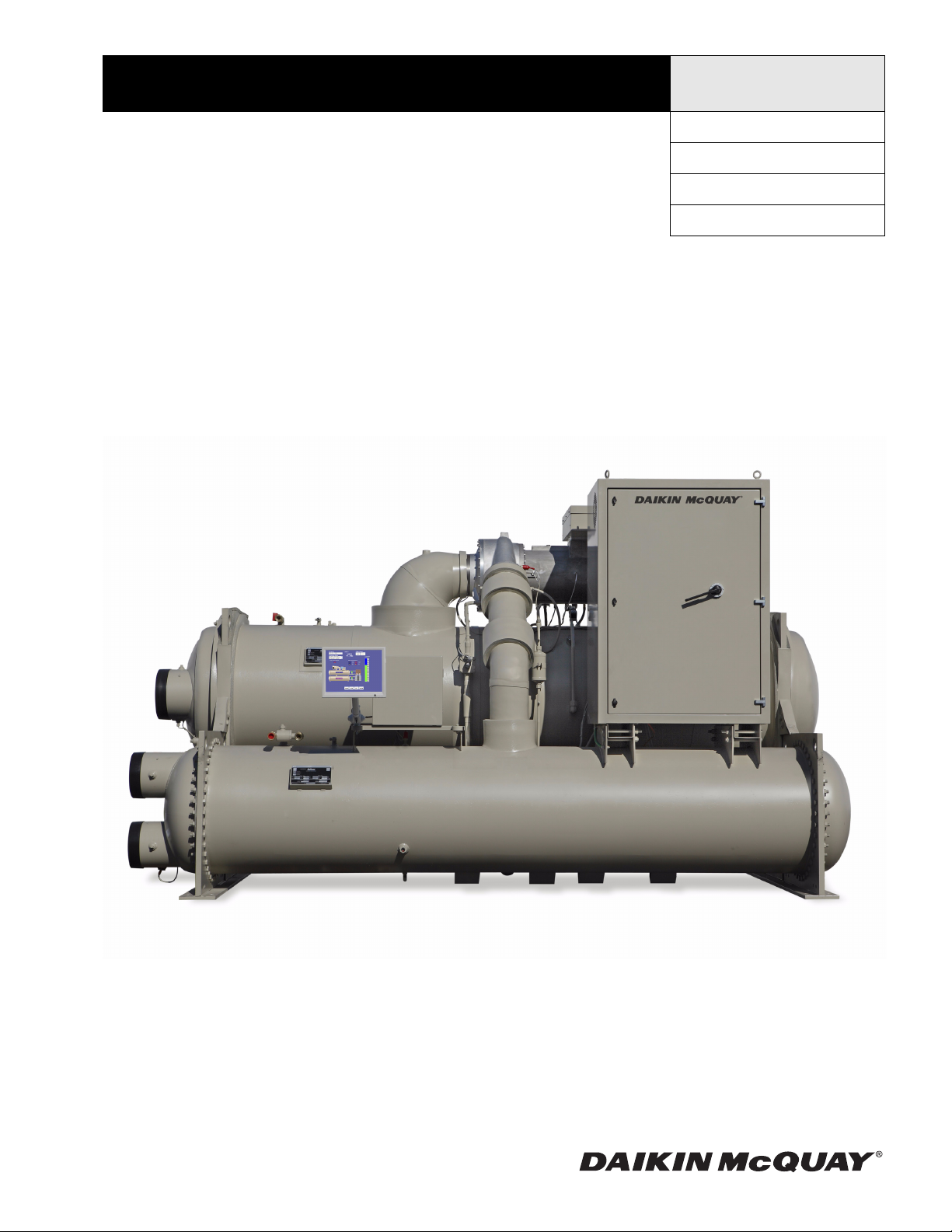
MagnitudeMagnetic Bearing Centrifugal Chillers
Model WME
400 to 700 tons (1400 to 2461 kW)
3/60/460-575
R-134a
© 2012 McQuay International
Page 2
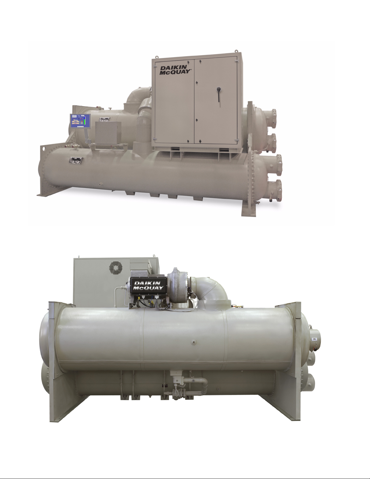
Note: The unit shown is for the default configuration; your unit may be configured differently. Refer to your selection for configuration.
Page 3
Contents
©2012 McQuay International. Illustrations and data cover the Daikin McQuay product at the time of publication and we reserve
the right to make changes in design and construction at anytime without notice. ™® The following are trademarks or registered
trademarks of their respective companies: BACnet from ASHRAE; L
ONMARK, LonTalk, LONWORKS, and the LONMARK logo are
managed, granted and used by L
ONMARK International under a license granted by Echelon Corporation; Modbus from Schneider
Electric; MicroTech E, Open Choices from McQuay International; LEED from the U.S. Green Building Council.
. . . . . . . . . . . . . . . . . . . . . . . . . . . . . . . . . . . . . . . 2
Introduction . . . . . . . . . . . . . . . . . . . . . . . . . . . . . . . 4
Installation . . . . . . . . . . . . . . . . . . . . . . . . . . . . . . . . 5
Installation . . . . . . . . . . . . . . . . . . . . . . . . . . . . 5
System Water Volume . . . . . . . . . . . . . . . . . . . 5
Water Piping . . . . . . . . . . . . . . . . . . . . . . . . . . 7
Relief Valves . . . . . . . . . . . . . . . . . . . . . . . . . . 9
Chiller Identification. . . . . . . . . . . . . . . . . . . . . . . . 11
Electrical Data . . . . . . . . . . . . . . . . . . . . . . . . . . . . 13
Electrical Notes . . . . . . . . . . . . . . . . . . . . . . . 14
Field Wiring Diagram . . . . . . . . . . . . . . . . . . . . . . . 15
Dimension Drawings . . . . . . . . . . . . . . . . . . . . . . . 16
Safety labels used in this manual:
Cautions indicate potentially hazardous situations, which can result in personal injury or equipment
damage if not avoided.
Warnings indicate potentially hazardous situations, which can result in property damage, severe
personal injury, or death if not avoided.
Dangers indicate a hazardous situation which will result in death or serious injury if not avoided.
Standard Head Connection Dimensions . . . . 27
Marine Water Box Dimensions . . . . . . . . . . . 28
Optional External Harmonic Filter Dimensions 29
Physical Data & Weights. . . . . . . . . . . . . . . . . . . . 31
Lifting and Mounting Weights . . . . . . . . . . . . 31
Physical Data - Evaporator . . . . . . . . . . . . . . 32
Physical Data - Condenser . . . . . . . . . . . . . . 32
Refrigeration Diagram . . . . . . . . . . . . . . . . . . . . . . 33
Optional External Harmonic Filter . . . . . . . . . . . . 34
Optional External Harmonic Filter . . . . . . . . . 34
Startup, Operation, and Storage . . . . . . . . . . . . . 37
Long Term Storage . . . . . . . . . . . . . . . . . . . . 39
CAUTION
WARNING
DANGER
Page 4
Introduction
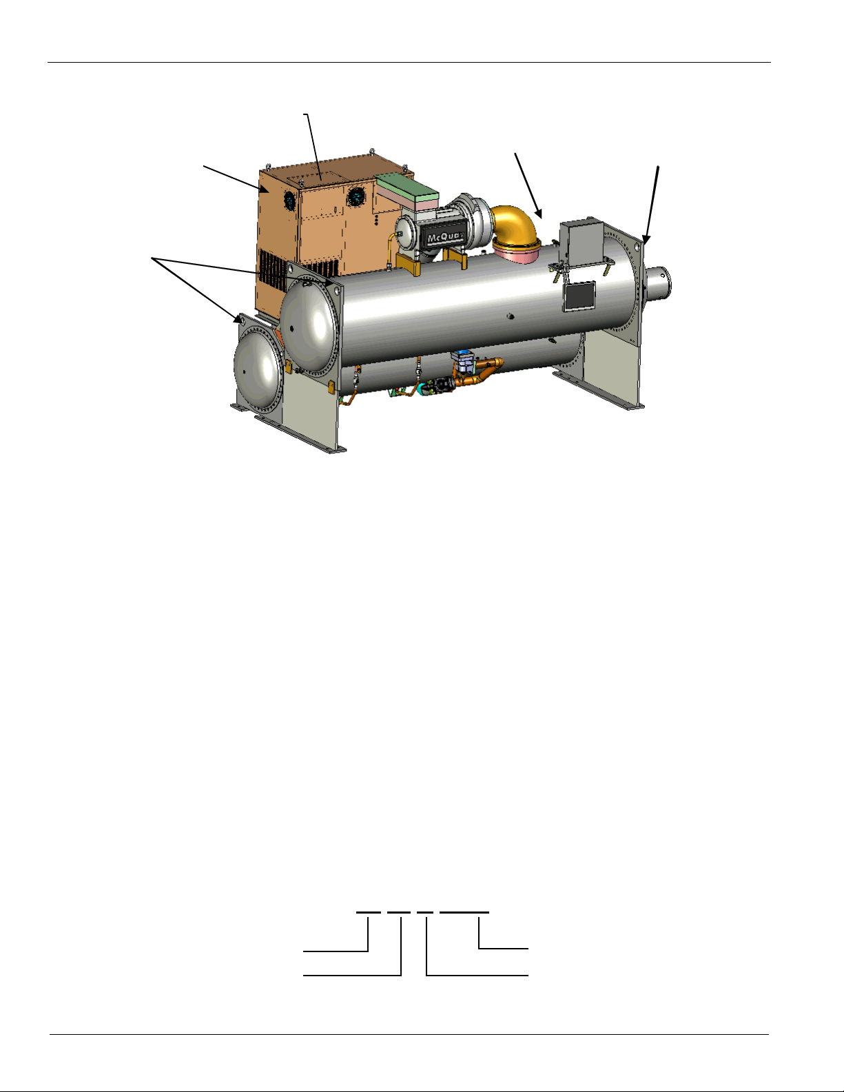
Lifting Points
Lifting P oint
Lifting Point (Outside
Corner Hidden)
VFD Power
Panel
Power Cable Entry
Note: This drawing is for general reference only. Refer to dimension drawings for actual location of components.
W M E 0500
Water-cooled
Magnetic Bearing
Vintage
Chiller Model
Introduction
Figure 1: Required Lifting Arrangement
General Description
Daikin McQuay Magnitude model WME frictionless
centrifugal chillers are complete, self-contained, automatically
controlled fluid chilling units. Each unit is completely
assembled and factory tested before shipment. Model WME is
cooling-only.
Each Magnitude Model WME unit features one compressor
connected to a condenser and evaporator. The chillers use
refrigerant R-134a to reduce the size and weight of the
package compared to negative pressure refrigerants and since
R-134a operates at a positive pressure over the entire operation
range, no purge system is required. The controls are pre-wired,
adjusted and tested. Only normal field connections such as
piping, electrical and interlocks, etc. are required, thereby
simplifying installation and increasing reliability. Most
necessary equipment protections and operating controls are
factory-installed in the control panel.
The chillers are designed for indoor, non-freezing locations. If
indoor freezing temperatures are possible, special procedures
Figure 2: Nomenclature
described in this manual must be followed to drain the unit.
Outdoor locations require a special weatherproof design. For
WME chillers selected with optional Retrofit Knockdown,
refer to IM Knockdown, available on www.daikinmcquay.com
for detailed dimensions and installation instructions.
Application
The procedures presented in this manual apply to standard
Model WME chillers. Refer to the Operating Manual, OMM
1034 for detailed information about chiller operation and the
MicroTech-E unit controller.
All Daikin McQuay centrifugal chillers are factory tested prior
to shipment and must be initially started at the job site by a
factory trained McQuay service technician. Failure to follow
this startup procedure can affect the equipment warranty.
The standard limited warranty on this equipment covers parts
that prove defective in material or workmanship. Specific
details of this warranty can be found in the warranty statement
furnished with the equipment.
4 IM 1033-3
Page 5
Installation
Installation
Installation
Receiving and Handling
The unit should be inspected immediately after receipt for
possible damage.
All Daikin McQuay centrifugal water chillers are shipped FOB
factory and all claims for handling and shipping damage are
the responsibility of the consignee.
Insulation corners from the evaporator's rigging hole locations
are shipped loose and should be glued in place after the unit is
finally placed. Neoprene vibration pads are also shipped loose.
Check that these items have been delivered with the unit.
If so equipped, leave the shipping skid in place until the unit is
in its final position. This will aid in handling the equipment.
Extreme care must be used when rigging the equipment to
prevent damage to the control panels or refrigerant piping. See
the certified dimension drawings included in the job submittal
for the center of gravity of the unit. Consult the local Daikin
McQuay sales office for assistance if the drawings are not
available.
The unit can be lifted by fastening the rigging hooks to the
four outside corners of the unit where the rigging eyes are
located. Lengthwise and crossway spreader bars must be used
between the rigging lines to prevent damage to the control
panels, piping and especially the large Variable Frequency
Drive (VFD) power panel located at one end of the unit. See
Figure 1, page 4.
outside edge of the feet. Most Model WME units have six
mounting feet although only the outer four are required. Six
pads are shipped and the installer can place pads under the
middle feet if desired.
Mounting
Make sure that the floor or structural support is adequate to
support the full operating weight of the unit.
It is usually not necessary to bolt the unit to the mounting slab
or framework; but should this be desirable, 1 1/8" (28.5 mm)
mounting holes are provided in the unit support at the four
corners.
CAUTION
Note: Units are shipped with refrigerant valves closed to isolate
the refrigerant for shipment. Valves must remain closed until
start-up by the McQuay technician.
Nameplates
There are several identification nameplates on the chiller:
"The unit nameplate is located on the side of the VFD panel.
This plate also lists the unit refrigerant charge, electrical data
and the unit model number and serial number, which should be
used when communicating with McQuay International.
"Vessel nameplates are located on the evaporator and
condenser. Along with other information, they have a National
Board Number (NB) and serial number, either of which
identifies the vessel (but not the entire unit).
Location and Mounting
The unit must be mounted on a level concrete or steel base and
must be located to provide service clearance at one end of the
unit for possible removal of evaporator tubes and/or condenser
tubes. The length of the vessel should be allowed at one end
for this purpose. Doors or removable wall sections can be
utilized for tube clearance. Evaporator and condenser tubes are
rolled into the tube sheets to permit replacement if necessary.
Minimum clearance at all other points, including the top, is 3
feet (1 meter) unless greater clearance is required by other
codes or job conditions. The National Electric Code (NEC)
can require four feet or more clearance in and around electrical
components and must be checked.
Location
The WME chillers are intended only for installation in an
indoor or weather protected area consistent with the NEMA 1
rating on the chiller, controls, and electrical panels. Equipment
room temperature for operating and standby conditions is 40°F
to 122°F (4.4°C to 50°C).
Vibration Pads
The shipped-loose neoprene vibration pads should be located
under the corners of the unit (unless the job specifications state
otherwise). They are installed to be flush with the sides and
"A compressor nameplate is located on the compressor itself
and contains identification numbers.
System Water Volume
All chilled water systems need adequate time to recognize a
load change, respond to that load change and stabilize, without
undesirable short cycling of the compressors or loss of control.
In air conditioning systems, the potential for short cycling
usually exists when the building load falls below the minimum
chiller plant capacity or on close-coupled systems with very
small water volumes.
Some of the things the designer should consider when looking
at water volume are the minimum cooling load, the minimum
chiller plant capacity during the low load period and the
desired cycle time for the compressors.
Assuming that there are no sudden load changes and that the
chiller plant has reasonable turndown, a rule of thumb of
"gallons of water volume equal to two to three times the
chilled water gpm flow rate" is often used.
A properly designed storage tank should be added if the
system components do not provide sufficient water volume.
Note: Water volumes can be found in the Physical Data tables
on page 27.
IM 1033-3 5
Page 6
Installation
30
35
40
45
50
55
60
65
0 102030405060708090100
ECWT (°F)
Percent Load
46°F LChW T
44°F LChW T
42°F LChW T
Bypass,MildWeatherOperation
Bypass,MildWeatherOperation
Condenser Water Temperature
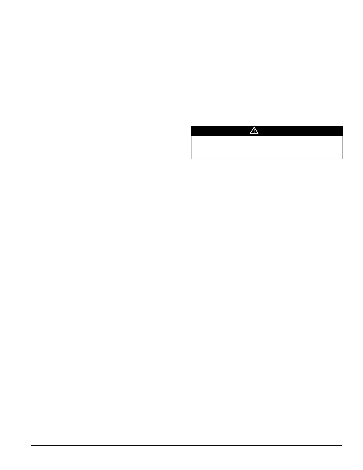
Figure 3: MODEL WME Minimum Entering Condenser
Water Temperature (EXV) (10 F Range at Full Load)
When the ambient wet bulb temperature is lower than design,
the entering condenser water temperature of Magnitude model
WME chillers can be lowered to improve chiller performance.
Chillers can start with entering condenser water temperatures
as low as 40°F (4.4°C). For short periods of time during
startup, the entering condenser water temperature can even be
lower than the leaving chilled water temperature.
Magnitude model WME chillers are equipped with electronic
expansion valves (EXV) and will run with entering condenser
water temperatures as low as shown in Figure 2 or as
calculated from the following equation on which the curves are
based:
MECWT = 5.25+(LWT)-0.75*DTFL*(PLD/100)+14 *(PLD/100)2
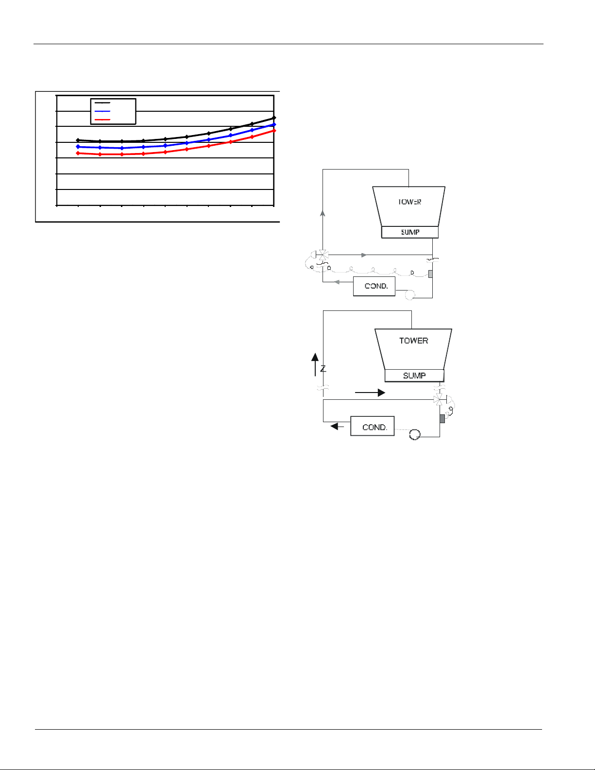
Figure 4 illustrates two temperature-actuated tower bypass
arrangements. The "Cold Weather" scheme provides better
startup under cold ambient air temperature conditions. The
bypass valve and piping are indoors and thus warmer, allowing
for warmer water to be immediately available to the condenser.
The check valve may be required to prevent air at the pump
inlet.
Figure 4: Possible Bypass Arrangements
Where:
MECWT = Min entering condenser water temperature
LWT = Leaving chilled water temperature
DTFL = Chilled Water Delta-T at full load
PLD = The percent chiller load point to be checked
For example; at 44°F LWT, 10°F Delta-T at full load, and 50%
full load operation, the entering condenser water temperature
could be as low as 49°F. This provides excellent operation
with water-side economizer systems.
Depending on local climatic conditions, using the lowest
possible entering condenser water temperature may be more
costly in total system power consumed than the expected
savings in chiller power would suggest, due to the excessive
fan power required.
In this scenario, cooling tower fans would continue to operate
at 100% capacity at low wet bulb temperatures. The trade-off
between better chiller efficiency and fan power should be
analyzed for best overall system efficiency. McQuay's Energy
Analyzer program can optimize the chiller/tower operation for
specific buildings in specific locales.
Even with tower fan control, some form of water flow control,
such as tower bypass, is recommended.
6 IM 1033-3
Condenser water temperature control
The standard MicroTech controller is capable of three stages of
tower fan control plus an analog control of either a three-way
tower-bypass valve or variable speed tower-fan motor. Stages
are controlled from condenser-water temperature. The threeway valve can be controlled to a different water temperature or
track the current tower stage. This allows optimum chilled
water plant performance based upon specific job requirements.
Pumps
The condenser water pump(s) must be cycled off when the last
compressor of the system cycles off. This will keep cold
condenser water from migrating refrigerant to the condenser.
Cold liquid refrigerant in the condenser can make start-up
difficult. In addition, turning off the condenser water pump(s)
when the chillers are not operating will conserve energy.
Include thermometers and pressure gauges at the chiller inlet
and outlet connections and install air vents at the high points of
piping. Where noise and vibration are critical and the unit is
Page 7
Installation
mounted on spring isolators, flexible piping and conduit
connections are necessary.
Variable Fluid Flow Rates and Tube Velocities
Many chiller system control and energy optimization strategies
require significant changes in evaporator and condenser water
flow rates. The Magnitude model WME chiller line is
particularly well suited to take full advantage of these energy
saving opportunities provided that the maximum and
minimum fluid flow rates are taken into consideration for a
specific application. The sales engineer has the flexibility to
use different combinations of shell size, number of tubes, and
pass arrangements to select the optimum chiller for each
specific application.
Both excessively high and excessively low fluid flow rates
should be avoided. Excessively high fluid flow rates and
correspondingly high tube velocities will result in high fluid
pressure drops, high pumping power, and potentially tube
corrosion and or tube corrosion damage. Excessively low fluid
flow rates and correspondingly low velocities should also be
avoided as they will result in poor heat transfer, high
compressor power, sedimentation and tube fouling.
Excessively high and low tube velocities can be particularly
problematic and damaging in open loop systems.
Rates of Fluid Flow Change
If it is decided to vary the evaporator water flow rate the rate
of change should not exceed 50% per minute and should not
exceed the minimum or maximum velocity limits as
determined by the Daikin McQuay chiller software program.
Vibration Mounting
The Magnitude model WME chillers are almost vibration-free.
Consequently, floor mounted spring isolators are not usually
required. Rubber mounting pads are shipped with each unit. It
is wise to continue to use piping flexible connectors to reduce
sound transmitted into the pipe and to allow for expansion and
contraction.
A properly designed storage tank should be added if the
system components do not provide sufficient water volume.
System Analysis
The McQuay Energy Analyzer program is an excellent tool to
investigate the entire system efficiency, quickly and accurately.
It is especially good at comparing different system types and
operating parameters. Contact your local Daikin McQuay sales
office for assistance on your particular application.
Water Piping
Vessel Drains at Start-up
Unit vessels are drained of water in the factory and are shipped
with the drain plugs in the heads removed and stored in the
control panel or with open ball valves in the drain hole. Be
sure to replace plugs or close the valves prior to filling the
vessel with fluid.
Evaporator and Condenser Water Piping
All evaporators and condensers come standard with ANSI/
AWWA C-606 grooved nozzles (also suitable for welding), or
optional flange connections. The installing contractor must
provide matching mechanical connections or transitions of the
size and type required.
CAUTION
If welding is to be performed on the mechanical or flange
connections, remove temperature sensors and thermal
dispersion flow switch from the nozzles to prevent damage to
those components. Also properly ground the unit or severe
damage to the MicroTech E unit controller can occur.
Water pressure gauge connection taps and gauges must be
provided in the field piping at the inlet and outlet connections
of both vessels for measuring the water pressure drops. The
pressure drops and flow rates for the various evaporators and
condensers are job specific and the original job documentation
can be consulted for this information.
System Water Volume
All chilled water systems need adequate time to recognize a
load change, respond to that load change and stabilize, without
undesirable short cycling of the compressors or loss of control.
In air conditioning systems, the potential for short cycling
usually exists when the building load falls below the minimum
chiller plant capacity or on close-coupled systems with very
small water volumes.
Some of the things the designer should consider when looking
Be sure that water inlet and outlet connections match certified
drawings and stenciled nozzle markings. The condenser is
connected with the coolest water entering at the bottom to
maximize subcooling.
CAUTION
When common piping is used for both heating and cooling
modes, care must be taken to provide that water flowing
through the evaporator cannot exceed 110°F which can cause
the relief valve to discharge refrigerant or damage controls.
at water volume are the minimum cooling load, the minimum
chiller plant capacity during the low load period and the
desired cycle time for the compressors.
The piping must be supported to eliminate weight and strain on
the fittings and connections. Piping must also be adequately
insulated. If a pump strainer is not close to a vessel, a
Assuming that there are no sudden load changes and that the
chiller plant has reasonable turndown, a rule of thumb of
cleanable 20-mesh water strainer must be installed in the water
inlet line. Sufficient shutoff valves must be installed to permit
"gallons of water volume equal to two to three times the
chilled water gpm flow rate" is often used.
IM 1033-3 7
Page 8
Installation
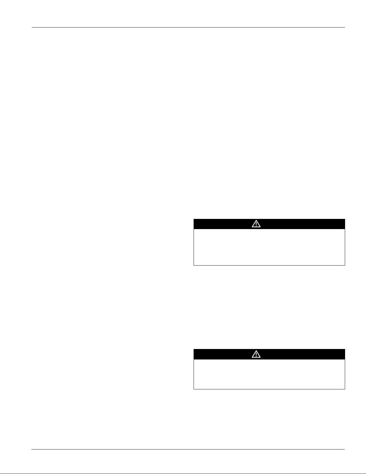
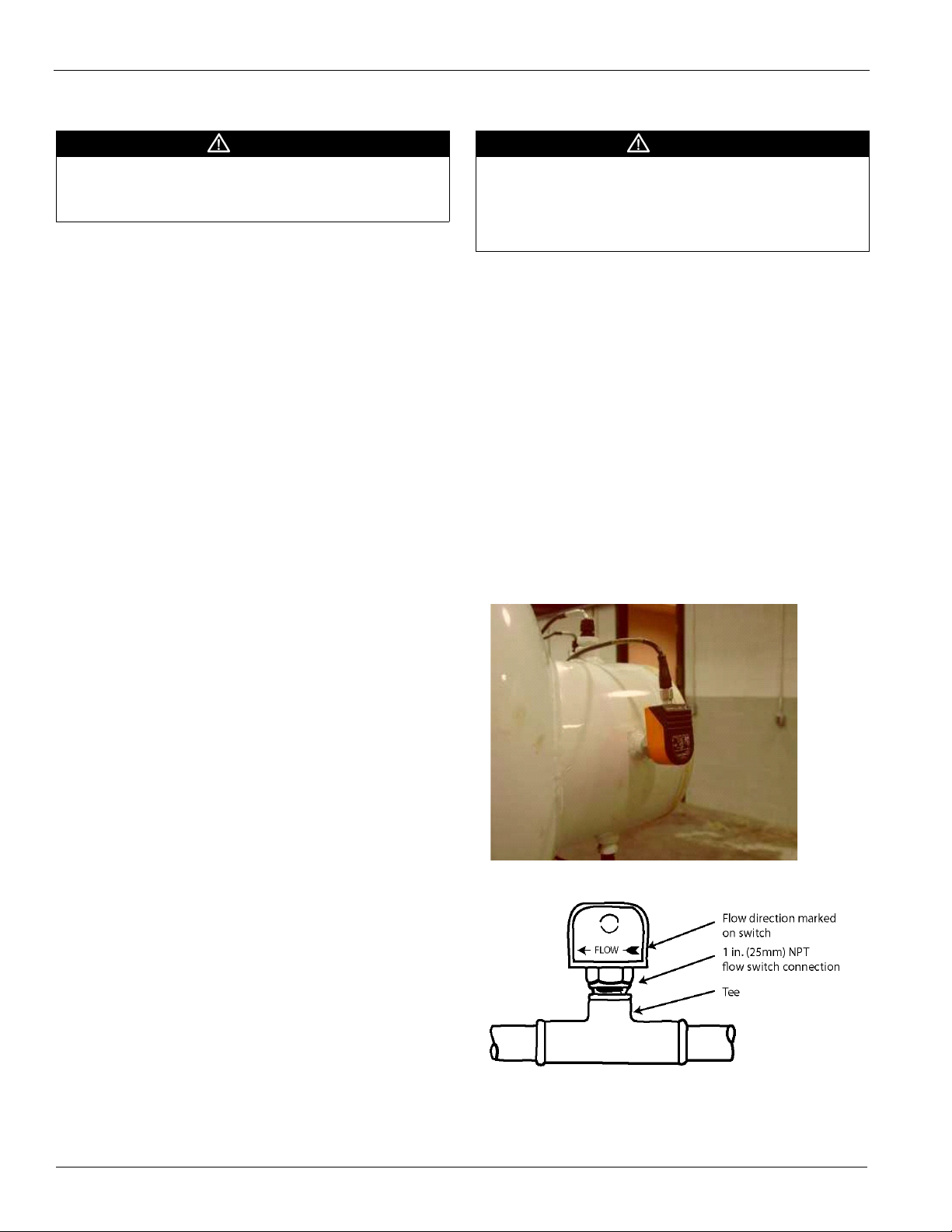
FactoryMountedFlowSwitch
Paddle‐typeFlowSwitch
draining the water from the evaporator or condenser without
draining the complete system.
CAUTION
Freeze Notice: Neither the evaporator nor the condenser is
self-draining; Both must be blown out to help avoid damage
from freezing.
The piping should also include thermometers at the inlet and
outlet connections and air vents at the high points.
The water heads can be interchanged (end for end) so that the
water connections can be made at either end of the unit. If this
is done, new head gaskets must be used and control sensors
relocated.
In cases where the water pump noise can be objectionable,
vibration isolation sections are recommended at both the inlet
and outlet of the pump. In most cases, it will not be necessary
to provide vibration eliminator sections in the condenser inlet
and outlet water lines. But they can be required where noise
and vibration are critical.
Mechanical Clamped Couplings
Use the following steps when installing clamped couplings:
1.Check for smooth pipe between the pipe end and the groove.
Remove any indentations, projections, or weld seams. Failure
to do this can result in a leaking joint.
bleed-off is operating. Atmospheric air contains many
contaminants, which increases the need for water treatment.
CAUTION
The use of untreated water will result in corrosion, erosion,
slime buildup, scaling, or algae formation. Water treatment
service must be used. McQuay International is not responsible
for damage or faulty operation from untreated or improperly
treated water.
Special care must be taken when utilizing open system water
that is usually not treated (such as lakes, rivers, and ponds).
Special tube and water head material may be required to
reduce damage from corrosion.
Flow Switches
Factory-mounted thermal dispersion flow switches are
provided as standard..
An additional paddle-type flow switch can be installed in the
vessel outlet piping as an added precaution to signal the
presence of adequate water flow to the vessels before the unit
can start. They also serve to shut down the unit in the event
that water flow is interrupted to guard against evaporator
freeze-up or excessive discharge pressure. They are not
necessary for unit operation.
Figure 5: Flow Switch Options
2.Apply a thin coat of Victaulic or silicon lubricant to the
gasket lips and exterior.
3.Position the gasket over the pipe end without overhanging
the pipe.
4.Join the pipes together and slide the gasket into position,
centering it between the groves.
5.Install the housing halves over the gasket, making sure that
the housing' keys engage the groves on both pipes.
6.Install the bolts and thread the nuts on hand tight. Make sure
that the oval heads of the bolts seat properly in the bolt holes.
7.Tighten the nuts evenly by alternating sides until metal to
metal contact is made on the housing bolt pads. Make sure that
the housing keys completely engage the pipe grooves.
Tower Filtering and Treatment
Owners and operators must be aware that if the unit is
operating with a cooling tower, cleaning and flushing the
cooling tower is required. Make sure tower blow-down or
If field-mounted flow switches (normally paddle-type) are
being used, electrical connections in the Unit Control Panel
must be made per the field wiring diagram on page 14. The
8 IM 1033-3
Page 9
Installation
normally open contacts of the flow switch must be wired
between the terminals. Flow switch contact quality must be
separate conduit from any high voltage conductors (115 VAC
and higher).
suitable for 24 VAC, low current (16ma). Wire switches in
Pipe Size (NOTE)
Min.
Adjst.
Max.
Adjst.
Note 1: A segmented 3-inch paddle (1, 2, and 3 inches) is furnished mounted, plus a 6-inch paddle loose.
Note 2: Flow rates for a 2-inch paddle trimmed to fit the pipe.
Note 3: Flow rates for a 3-inch paddle trimmed to fit the pipe.
Note 4: Flow rates for a 3-inch paddle.
Note 5: Flow rates for a 6-inch paddle
Note 6: There is no data for pipe sizes above 8-inch. A switch minimum setting should provide protection against no flow and close well before design flow is
Flow
No Flow
Flow
No Flow
reached.
Freeze Notice: Neither the evaporator nor the condenser is
self-draining; Both must be blown out to help avoid damage
from freezing.
inch 1 1/4 1 1/2 2 2 1/2 3 4 5 6 8
mm 32 (2) 38 (2) 51 63 (3) 76 102 (4) 127 (4) 153 (4) 204 (5)
gpm
Lpm
gpm
Lpm
gpm
Lpm
gpm
Lpm
5.8 7.5 13.7 18.0 27.5 65.0 125.0 190.0 205.0
1.3 1.7 3.1 4.1 6.2 14.8 28.4 43.2 46.6
3.7 5.0 9.5 12.5 19.0 50.0 101.0 158.0 170.0
0.8 1.1 2.2 2.8 4.3 11.4 22.9 35.9 38.6
13.3 19.2 29.0 34.5 53.0 128.0 245.0 375.0 415.0
3.0 4.4 6.6 7.8 12.0 29.1 55.6 85.2 94.3
12.5 18.0 27.0 32.0 50.0 122.0 235.0 360.0 400.0
2.8 4.1 6.1 7.3 11.4 27.7 53.4 81.8 90.8
CAUTION
Field Insulation Guide
Factory insulation is an available option (0.75" or 1.5"). If
field insulated, the following components should be insulated
to prevent condensation on Magnitude model WME chillers.
The piping should also include thermometers at the inlet and
outlet connections and air vents at the high points.
The water heads can be interchanged (end for end) so that the
water connections can be made at either end of the unit. If this
is done, new head gaskets must be used and control sensors
relocated.
In cases where the water pump noise can be objectionable,
vibration isolation sections are recommended at both the inlet
and outlet of the pump. In most cases, it will not be necessary
to provide vibration eliminator sections in the condenser inlet
and outlet water lines. But they can be required where noise
and vibration are critical.
System Pumps
Operation of the chilled water pump can be to:
1 Cycle the pump with the unit enable
2 Operate continuously
3 Start automatically by a remote source
The cooling tower pump must cycle with the compressor. The
holding coil of the cooling tower pump motor starter must be
rated at 115 volts, 60 Hz, with a maximum volt-amperage
rating of 100. A control relay is required if the voltageamperage rating is exceeded. See the Field Wiring Diagram or
in the cover of control panel for proper connections.
Table 1: Insulation Guide
Evaporator
Motor Cooling
Stator cooling Evaporator Tube
Notes:
1 The discharge line can also be insulated for sound reduction, as an option.
2 The compressor body does not require insulation.
3 Insulation quantity: E3612=129 sq.ft. (12 m
Evaporator Water
Suction Elbow
2
), E3012=115 sq ft. (11 m2).
Expansion valve
VFD cooling
Relief Valves
Figure 6: Typical Vent Piping
All interlock contacts must be rated for no less than 10
inductive amps. The alarm circuit provided in the control
center utilizes 115-volts AC. The alarm used must not draw
more than 10 volt amperes.
IM 1033-3 9
Page 10
Installation
D
Common
DD D
n
1
2
2
22
05
....
.
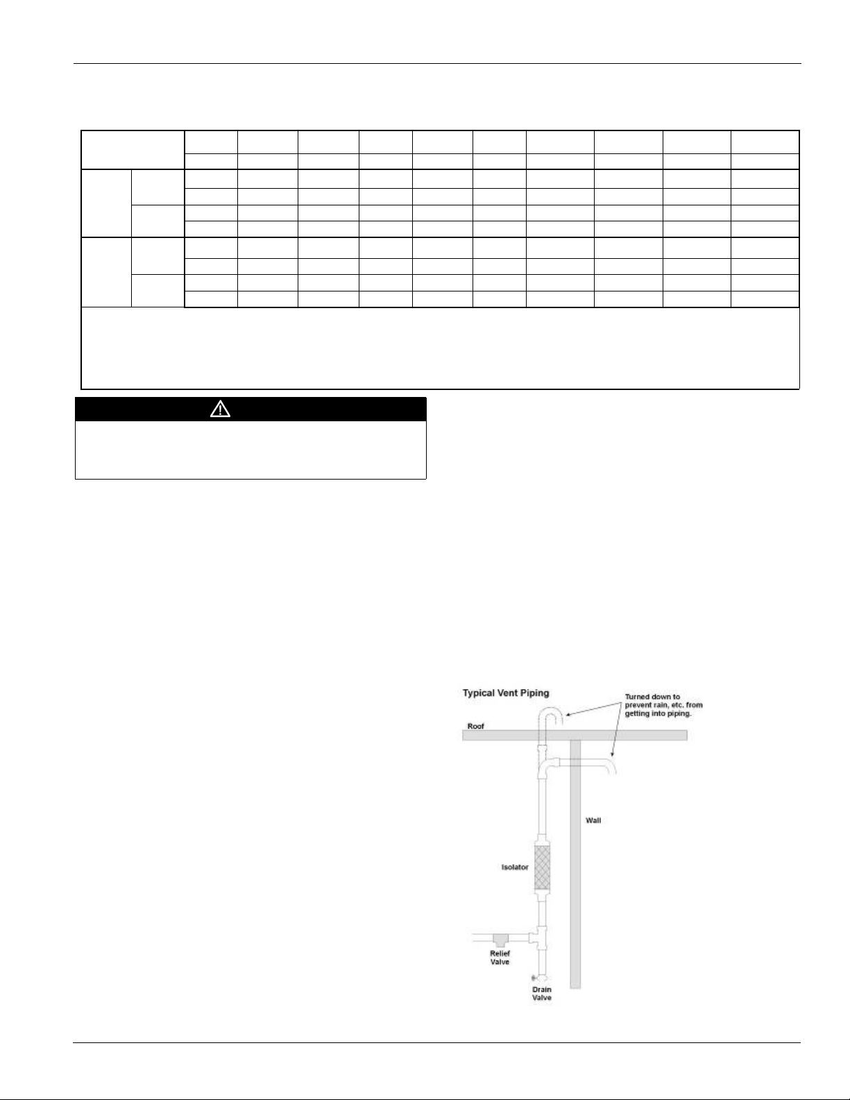
As a safety precaution and to meet code requirements, each
chiller is equipped with pressure relief valves located on the
condenser and evaporator vessels for the purpose of relieving
excessive refrigerant pressure (caused by equipment
malfunction, fire, etc.) to the atmosphere. Most codes require
that relief valves be vented to the outside of a building, and
this is a desirable practice for all installations. Relief piping
connections to the relief valves must have flexible connectors.
Whenever vent piping is installed, the lines must be run in
accordance with local code requirements; where local codes do
not apply, the latest issue of ANSI/ASHRAE Standard 15 code
recommendations must be followed.
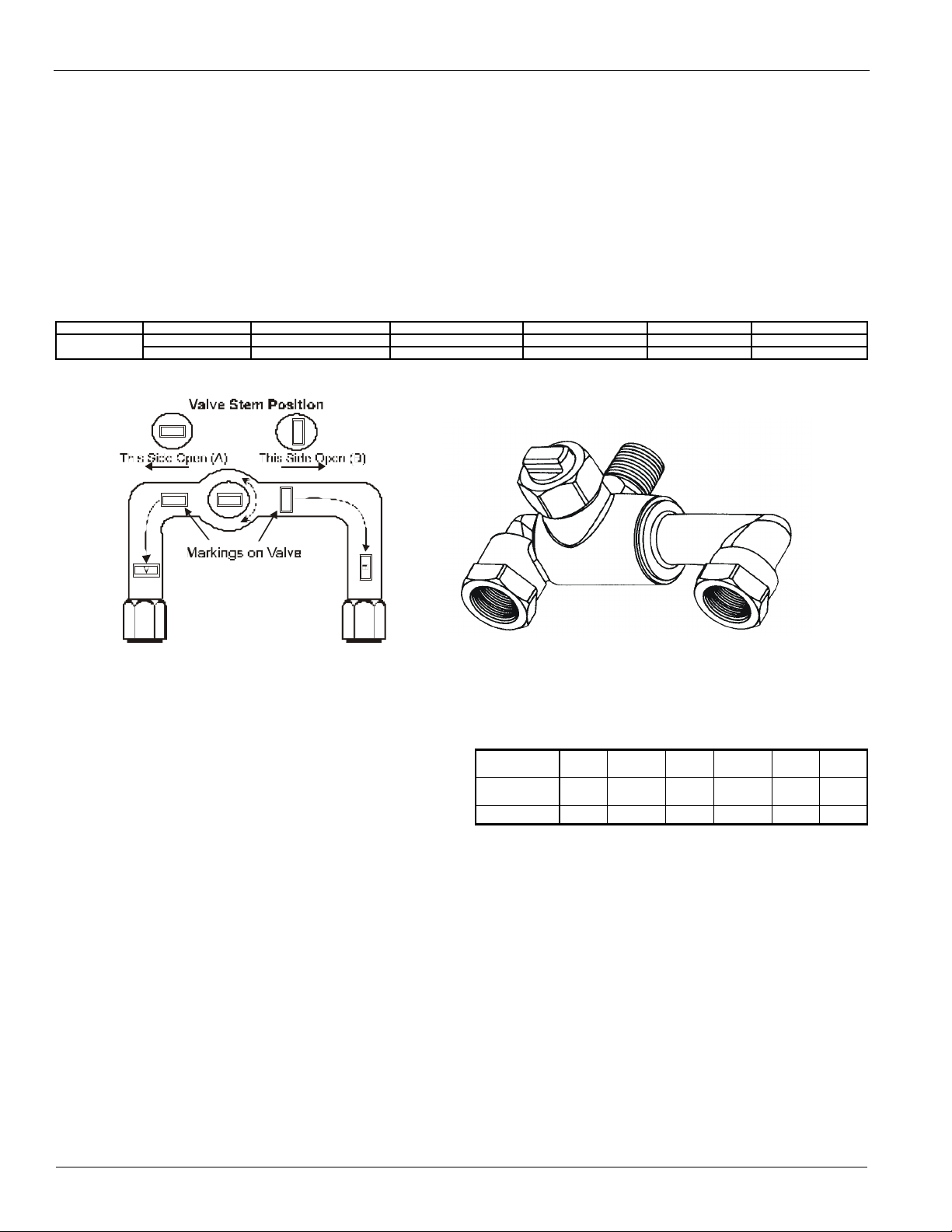
Condensers have two relief valves as a set with a three-way
valve separating the two valves (large condensers will have
two such sets). One valve remains active at all times and the
second valve acts as a standby.
Note: Remove plastic shipping plugs (if installed) from the
inside of the valves prior to making pipe connections.
Table 2: Relief Valve Data
Model Relief Valve Location Pressure Setting Discharge Cap. Conn. Size No. of Valves
WME
Figure 7: Condenser 3-Way Valve
Evaporator Top of Evaporator 200 psi 75.5 lb air/min 1 in. FPT 1
Condenser Top of Condenser 200 psi 75.5 lb air/min 1 in. FPT 2
Refrigerant Vent Piping
Twin relief valves mounted on a transfer valve are used on the
condenser so that one relief valve can be shut off and removed,
leaving the other in operation. Only one of the two is in
operation at any time.
Vent piping is sized for only one valve of the set since only one
can be in operation at a time. In no case would a combination
of evaporator and condenser sizes require more refrigerant
than the pumpdown capacity of the condenser. Condenser
pumpdown capacities are based on the current ANSI/
ASHRAE Standard 15 that recommends 90% full at 90°F
(32°C). To convert values to the older AHRI standard,
multiply pumpdown capacity by 0.888.
Sizing Vent Piping (ASHRAE Method)
Relief valve pipe sizing is based on the discharge capacity for
the given evaporator or condenser and the length of piping to
be run. Discharge capacity for R-134a vessels is calculated
using a complicated equation that accounts for equivalent
length of pipe, valve capacity, Moody friction factor, pipe ID,
outlet pressure and back pressure. The formula, and tables
derived from it, are contained in ASHRAE Standard 15-2001.
Using the ASHRAE formula and basing calculations on the
225 psi design yields a conservative pipe size, which is
summarized in Tabl e 3. The table gives the pipe size required
per relief valve. When valves are piped together, the common
piping must follow the rules set out in the following paragraph
on common piping.
Table 3: Relief Valve Piping Sizes
Equivalent
length (ft)
Pipe Size inch
(NPT)
Moody Factor 0.0209 0.0202 0.0190 0.0182 0.0173 0.0163
2.2 18.5 105.8 296.7 973.6 4117.4
1 1/4 1 1/2 2 2 1/2 3 4
NOTE: A 1-inch pipe is too small for the flow from the valves.
A pipe increaser must always be installed at the valve outlet.
Common Relief Valve Piping
According to ASHRAE Standard 15, the pipe size cannot be
less than the relief valve outlet size. The discharge from more
than one relief valve can be run into a common header, the
area of which cannot be less than the sum of the areas of the
connected pipes. For further details, refer to ASHRAE
Standard 15. The common header can be calculated by the
formula:
The above information is a guide only. Consult local codes
and/or latest version of ASHRAE Standard 15 for sizing data.
10 IM 1033-3
Page 11
Chiller Identification
ater-Cooled C
Unit Size
Single Circuit
Motor Code
M2 – Standard
M3 –
Low THD (WME0500)
Voltage Code, 3/60/480
A – 3/60/ 440V
R – 3/ 60/460V
S – 3/60/480V
Sound Package
Evap: Size, dia (in)
-length (ft)
Evap Tubes: B=Count, E=Type
Evap Heads: 2=Pass, R=Right, A=Conn, Type
Evap Design Press: Ref=200 psi
Waterside: C4=150 psi C5 =300 psi
Leaving Water Temp (x 10)
NOT USED
Cond: Size, dia (in) length (ft)
Cond. Tubes: Type and Count
Heads: 2=Pass, R=Right, A=Conn, Type
Evap Tube Sheet and Head Material
Refrigerant
Compressor Revision
WME 0500S S M2 S S AAB E3612 BE 2RA C4 440 CC Y A C3012 BYLL 2RA C4 1050 CC Y A A 134
1 2 3 4 5 6 7 8 9 10 11 12 13 14 15 16 17 18 19 20 21 22 23 24 25
Passes: 1, 2, 3
Handednesss: R-Right; L-Left
Connection: A-Victaulic; B- Flanged; C/E-Marine Waterbox
Evaporator Revision
Passes: 1, 2, 3
Handednesss: R-Right; L-Left
Connection: A-Victaulic; B- Flanged; C/E-Marine Waterbox
Cond Design Press: Ref=200 psi
Waterside: C4=150 psi C5 =300 psi
Max. Leaving Water Temp F (x 10)
Cond. Tube Sheet and Head Material
NOT USED
Compressor Revision
ASME Pressure Vessel Code
M4 –
Low THD (WME0700)
t#$%wFWBQPSBUPSUVCFT
t&'(wFWBQPSBUPSUVCFT
t+,..JYFEFWBQPSBUPSUVCFT
If code begins with:
t-/1wFWBQPSBUPSUVCFT
t"#$wFWBQPSBUPSUVCFT
If code begins with:
Figure 8: Magnitude Code String Chiller Identification
Chiller Identification
W
IM 1033-3 11
hiller
Page 12

Chiller Identification
080 E1 YY EAYYY MBYYYYYY YYYY YY B 1 4 B Y Y 5 1 B A 0500 U Y H Y Y Y Y 2 B
26 27 28 29 30 31 32 33 34 35 36 37 38 39 40 41 42 43 44 45 46 47 48 49 50 51 52
Refrigerant Weight
Expansion Valve
NOT USED
Controls: MicroTech-E
BAS Card:
MB = Modbus; LY = LONworks; BM= Bacnet
NOT USED
Shell and Head Insulation:
H_ = 3/4” Insulation
3_ = 1.5” Insulation
YY = None
Flow Switch (standard)
Standard Finish
Crating:
4=Shipping Bag/Wood Skid (std.)
Refrigerant:
A - Full Charge
B/N - Holding Charge
Special
Future
Knockdown:
Y-None
1-Type I
2- Type II
3- Type III
Standard/Certied/Witness Test Option
ARI/ETL/CETL Listing
Unit Revision
Chiller Startup (Std on Domestic)
Extended Warranty
Refrigeration Tons
Standard 1st Year Warranty
Future
Future
Future
Future
Refrigerant Warranty
Delayed Start Warranty
Figure 9: Magnitude Code String Chiller Identification
12 IM 1033-3
Page 13
Electrical Data
Wiring, fuse and wire size must be in accordance with the
National Electric Code (NEC).
Important: Voltage unbalance not to exceed 2% with a
resultant current unbalance of 6 to 10 times the voltage
unbalance per NEMA MG-1, 1998 Standard. This is an
important restriction that must be adhered to.
Power Wiring
Power entrance is on top of the enclosure. Remove cover plate
when making hole to avoid entrance of foreign material into
the enclosure.
Power connection lug size is 3/0 AWG - 500kcmil, three
conductors per phase
The ground connection is a stand-off adjacent to the circuit
breaker, marked "MGND". Field provide a 3/8-16 x ¾ in.
screw with a flat washer and lock washer and appropriate "O"
terminal.
CAUTION
Qualified and licensed electricians must perform wiring.
Shock hazard exists.
Electrical Data
CAUTION
Connections to terminals must be made with copper lugs and
copper wire..
Use only copper supply wires with ampacity based on 75°C
conductor rating. (Exception: for equipment rated over 2000
volts, 90°C or 105°C rated conductors should be used).
The VFD nameplate will indicate the RLA setting required in
the MicroTech-E controller. The RLA setting is for the VFD
output amps not the input amps. Follow name plate values for
output RLA.
Power Factor Correction Capacitors
Do not use power factor correction capacitors with WME
chillers. They can cause harmful electrical resonance in the
system. Correction capacitors are not necessary since VFDs
inherently maintain high power factors.
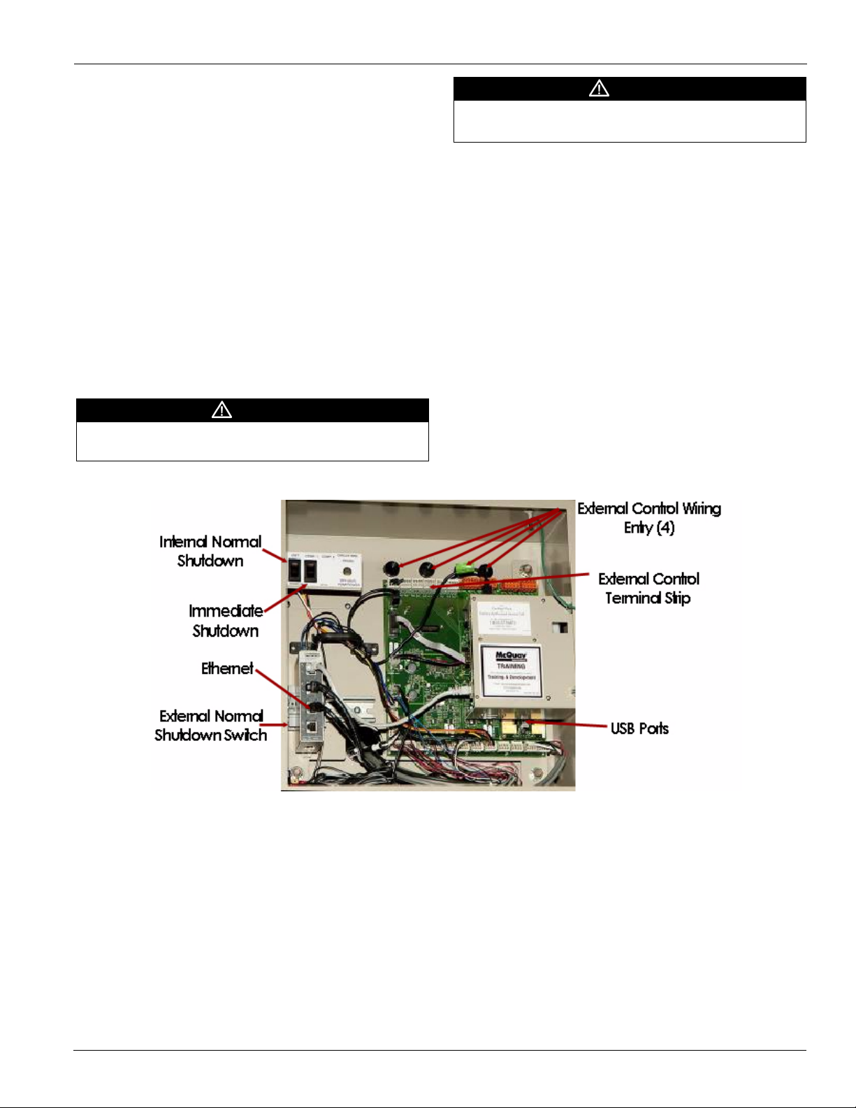
Control Wiring
The control circuit power on Magnitude model WME chillers
is supplied by the unit-mounted VFD.
Figure 10: Unit Control Panel
IM 1033-3 13
Page 14

Electrical Data
Electrical Notes
1 Units are available for 460 or 440 to 480 VAC at 60 Hz.
2 Wiring, fuse and wire size must be in accordance with
the National Electric Code (NEC).
3 Important: Voltage unbalance not to exceed 2%.
Power Wiring
Use only copper supply wires with ampacity based on 75°C
conductor rating. Connections to terminals must be made with
copper lugs and copper wire.
Lug size range is: (3) 3/0 AWG - 500 kc mil.
Power Factor Correction Capacitors
Do not use power factor correction capacitors with(WME
chillers. Doing so can cause harmful electrical resonance in the
system. Correction capacitors are not necessary since VFDs
inherently maintain high power factors
Short Circuit Current Ratings
The standard short circuit rating is 35kA for 460 V. Optional
high short circuit current ratings are available for 65kA, and
100kA with a matching circuit breaker.
The optional circuit breaker must be sized to meet these
ratings.
3-Phase vs. 6-phase Motors
WME 500 motors are designated as M2 or M3.
• "M2 motors are standard 3-phase and the VFD performs
similar to a 6-pulse drive.
• "M3 motors are 6-phase (connected to a 3-phase power
supply) and the VFD performs similar to a 12-pulse drive.
They provide increased protection against harmonic
distortion, but are not required on most applications.
Notes for field wiring diagram
1 All line-side wiring must be in accordance with the NEC
and be made with copper wire and copper lugs only.
2 A customer furnished 24 to 240 Vac power for alarm
relay coil may be connected at J18. Maximum rating of
the alarm relay coil is 25 VA.
3 Remote on/off control of unit can be accomplished by
connecting a set of isolated dry contacts at J25.
4 If field supplied pressure differential flow switches are
used, they must be installed across the vessel and not the
pump. They must provide isolated dry contacts at J27.
5 An optional customer supplied 25 VA maximum coil
rated, chilled water pump relay (one or two) may be
wired as shown. This option will cycle the chilled water
pump in response to chiller demand.
6 The condenser water pump must cycle with the unit. A
customer supplied 25 VA maximum coil rated,
condenser water pump relay (one or two) must be wired
as shown. Units used in a free-cooling application must
have condenser water above 50°F before starting.
7 Optional customer supplied 25 VA maximum coil rated
cooling tower fan relays may be wired as shown. This
option will cycle the cooling tower fans as prescribed by
the tower control set points.
8 External 4-20mA signals can be wired to J23 for leaving
(chilled) water reset and to J26 for demand limit.
WME 700 motors are 6-phase and designated as M4. The VFD
performs similar to a 12-pulse drive.
14 IM 1033-3
Page 15

Field Wiring Diagram
Figure 11: Field Wiring Diagram
Field Wiring Diagram
IM 1033-3 15
Page 16

Dimension Drawings
Minimum 14’ Clearance for tube removal
TOP VIEW
Minimum 3’ Clearance
Minimum 3’ Clearance on all sides and top of chiller; Minimum 14’ clearance on one side for tube removal.
Minimum 3’ Clearance
Minimum 3’ Clearance
Dimension Drawings
Drawing Notes
1 All dimensions are in inches [millimeters] unless noted
otherwise.
2 Final connections must allow for 0.5 inch +/- (12.7mm)
manufacturing tolerances.
3 1.00-inch FPT [25.4 mm] evaporator and condenser
relief valves must be piped per ANSI / ASHRAE 15.
Number of relief valves is 1 per evaporator and 2 per
condenser.
4 .375 inch [9 mm] suction nozzle relief valve must be
piped per ANSI / ASHRAE 15.
5 MinimumClearances (See Figure 12):
• Installation layout should be designed by qualified personnel familiar with local codes.
• Allow a minimum of 3 ft. on all for sides and the top
sides of chiller to allow for service access.
• Provide a minimum of 3 ft. clearance in front of chiller
starter panel or according to NEC or local codes.
• Provide a minimum of 14 ft. clearance on one end of the
chiller for tube removal.
6 Electric Panels- Most codes require 48 inches (1219 mm)
clearance in front of control boxes and electrical panels.
Check codes for your location.
7 3.25-inch [83mm] diameter lifting holes are provided.
See installation manual IM 1033 (available on
www.daikinmcquay.com) for lifting instructions.
8 All water connections are given in standard U.S. pipe
sizes. Standard connections are suitable for welding or
victaulic couplings.
Figure 12: Minimum Clearances
9 Unit shown has standard right-hand water connections.
Left-hand connections are available for either vessel. For
right hand evaporator the inlet and outlet nozzles are
reversed. ANSI-flanged connections are available upon
request. When using ANSI-flanged connections add 0.5
inch [13 mm] to each flanged end.
10 Dimensions shown are for units (evaporator / condenser)
with standard design pressures. The waterside design
pressure is 150 PSI {1034 kPa}. Consult the factory for
unit dimensions with higher design pressures.
11 The unit vibration isolator pads are provided for field
installation and when fully loaded are 0.250 inches [6
mm] thick.
12 These values are for units with standard wall thickness
copper tubing only.
13 The shipping skid adds 4.00 inches [105 mm] to the
overall unit height.
14 If main power wiring is brought up through the floor, this
wiring must be outside the envelope of the unit.
15 The unit is shipped with an operating charge of
refrigerant.
16 Optional marine water box connections are available
upon request.
17 To determine the evaporator and condenser tube size,
compare the Code Item Report generated by the selection
program with Figure 3, page 8. Code items 9 and 17 will
give the evaporator and condenser tube sizes,
respectively.
18 When equipped with the factory-mounted harmonic filter
WME 500 units with the M2 motor have the two-door
power panel as shown in Figure 14 and Figure 16.
16 IM 1033-3
Page 17

Dimension Drawings
5.3
133
145.4
3694
5.3
133
170.4
EVAP. (UNIT OVERALL)
4329
169.0
COND.
4292
36.6
COND.
RELIEF
VALVE
931
68.3
EVAP.
RELIEF
VALVE
1734
3
3
5, 8, 9
5, 8, 9
5, 8, 9
FRONT VIEW
X
Y
COND
EVAP
UNIT
CONT.
BOX
6
60.5
VHD
HEIGHT
1537
19.3
489
47.0
1195
69.0
1753
77.0
UNIT O/A
1956
96.8
UNIT
O/A
2460
13.8
349
52.3
1327
68.5
1741
2.5
63
5
5, 11,13
RIGHT VIEW
Z
Y
17.0
433
3.1
80
7.6
193
46.9
1192
13.7
348
148.2
3764
3
3
TOP VIEW
O.I.T.S.
X
Z
LB
LF
RF
RB
148.2
3764
16.0
406
7.2
183
40.3
1023
1.4
TYP.
35
40.1
1019
92.7
2356
4.0
TYP.
102
25.5
646
8.0
TYP.
203
1.13
TYP.
MTG
HOLE
29
77.0
1956
5.1
129
UNIT CONT.
BOX
6, 14
ENVELOPE OF UNIT
14
MOUNTING FEET
X
Z
TOP VIEW
ALL DIMENSIONS ARE IN DECIMAL
INCHES AND [MILLIMETERS]
333904501
DRAWING NUMBER00REV.
This information is accurate at time of
printing. McQuay reserves the right to
change design, specication and product
data without notice. Purchaser must
determine that the equipment is t and
sucient for the job specications. No
change to this data may be made unless
approved in writing by McQuay. McQuay's
Limited Product Warranty applies to all
McQuay equipment.
WME0500 M2: 440V (60Hz), 460V (60Hz),
480V (60Hz)
Figure 13: WME0500 - E3612/C3012 - 2-pass - M2 Standard Motor (60Hz - 440/460/480V) (See page 16 for drawing notes.)
IM 1033-3 17
Page 18

Dimension Drawings
5.3
133
145.4
3694
5.3
133
170.4
EVAP. (UNIT OVERALL)
4329
169.0
COND.
4292
36.6
COND.
RELIEF
VALVE
931
68.3
EVAP.
RELIEF
VALVE
1734
3
3
5, 8, 9
5, 8, 9
5, 8, 9
FRONT VIEW
X
Y
COND
EVAP
UNIT
CONT.
BOX
19.3
489
47.0
1195
69.0
1753
77.0
UNIT O/A
1956
13.8
349
52.3
1327
68.5
1741
2.5
63
60.0
VFD
HEIGHT
1523
96.3
UNIT
O/A
2446
5
5, 11,13
RIGHT VIEW
Z
Y
17.0
433
3.1
80
7.6
193
46.9
1192
13.7
348
148.2
3764
3
3
TOP VIEW
O.I.T.S.
X
Z
LB
LF
RF
RB
148.2
3764
16.0
406
7.2
183
1.4
35
40.1
1019
83.5
2122
4.0
TYP.
102
27.8
707
8.0
TYP.
203
1.13
TYP.
MTG
HOLE
29
77.0
1956
5.1
129
54.0
1372
UNIT CONT.
BOX
6, 14
ENVELOPE OF UNIT
14
MOUNTING FEET
X
Z
TOP VIEW
6
333904601
DRAWING NUMBER00REV.
ALL DIMENSIONS ARE IN DECIMAL
INCHES AND [MILLIMETERS]
WME0500 M2: 380V (50Hz), 400V (50Hz),
415V (50Hz), 380V (60Hz),
575V (60Hz).
WME0500 M3: 380V (50Hz), 400V (50Hz),
415V (50Hz), 380V (60Hz),
440V (60Hz), 460V (60Hz),
480V (60Hz), 575V (60Hz).
This information is accurate at time of
printing. McQuay reserves the right to
change design, specication and product
data without notice. Purchaser must
determine that the equipment is t and
sucient for the job specications. No
change to this data may be made unless
approved in writing by McQuay. McQuay's
Limited Product Warranty applies to all
McQuay equipment.
Figure 14: WME0500 - E3612/C3012 - 2-pass - M2 Standard Motor (50Hz 380/400/415V - 60Hz 380/575V)
WME0500 - E3612/C3012 - 2-pass - M3 Low THD Motor (50Hz 380/400/415V - 60Hz 380/440/460/480/575V)
WME0500 - E3612/C3012 - 2-pass - M2 Standard Motor (60Hz 380/460V) with Factory-mounted Harmonic Filter
(See page 16 for drawing notes.)
18 IM 1033-3
Page 19

32.6
COND
RELIEF
VALVES
829
61.1
EVAP
RELIEF
VALVE
1551
5.3
133
164.6
COND.
4181
145.4
3694
5.3
133
169.0
EVAP. UNIT OVERALL
4292
5, 8, 9
5, 8, 9
3
3
5, 8, 9
Y
X
FRONT VIEW
UNIT
CONT.
BOX
58.0
1473
68.4
UNIT O/A
1737
42.8
1087
92.9
UNIT
O/A
2359
48.6
1235
15.6
397
61.8
1568
66.0
1676
17.3
438
60.5
VFD
HEIGHT
1537
2.5
63
5,11,13
5
Z
Y
SIDE VIEW
148.2
3764
13.7
348
38.9
989
5.1
130
17.0
433
3.1
80
3
3
X
Z
TOP VIEW
O.I.T.S.
LB
LF
RF
RB
66.0
1676
1.4
35
40.1
1019
16.0
406
7.2
183
4.0
TYP.
102
8.0
TYP.
203
148.2
3764
1.13
TYP.
MTG.
HOLE
29
21.0
533
92.7
2356
40.3
1023
25.4
645
2.6
65
148.2
3764
X
Z
TOP VIEW
UNIT CONT.
BOX
ENVELOPE OF UNIT
MOUNTING FEET
6
6, 14
14
ALL DIMENSIONS ARE IN DECIMAL
INCHES AND [MILLIMETERS]
333904101
DRAWING NUMBER00REV.
WME0500 M2: 440V (60Hz), 460V (60Hz),
480V (60Hz)
This information is accurate at time
of printing. McQuay reserves the
right to change design, specication
and product data without notice.
Purchaser must determine that the
equipment is t and sucient for the
job specications. No change to this
data may be made unless approved
in writing by McQuay. McQuay's
Limited Product Warranty applies to
all McQuay equipment.
Dimension Drawings
Figure 15: WME0500 - E3012/C2612 -2-pass, M2 Standard Motor (60 Hz 440/460/480V) (See page 16 for drawing notes.)
IM 1033-3 19
Page 20

Dimension Drawings
32.6
COND
RELIEF
VALVES
829
61.1
EVAP
RELIEF
VALVE
1551
5.3
133
164.6
COND.
4181
145.4
3694
5.3
133
169.0
EVAP.(UNIT OVERALL)
4292
5, 8, 9
5, 8, 9
3
3
5, 8, 9
FRONT VIEW
Y
X
UNIT
CONT.
BOX
58.0
1473
70.7
UNIT OVALL
1796
42.8
1087
61.8
1568
66.0
1676
17.3
438
60.0
VFD
HEIGHT
1523
51.0
1294
18.0
456
92.3
UNIT
O/A
2345
2.5
63
5,11,13
5
SIDE VIEW
Y
Z
148.2
3764
13.7
348
38.9
989
5.1
130
17.0
433
3.1
80
3
3
TOP VIEW
LB
LF
RF
RB
O.I.T.S.
X
Z
66.0
1676
1.4
TYP.
35
40.1
1019
16.0
406
7.2
183
30.1
764
83.5
2122
54.0
1372
4.0
TYP.
102
23.4
594
8.0
TYP.
203
148.2
3764
2.6
65
148.2
3764
1.13
TYP.
MTG.
HOLE
29
TOP VIEW
ENVELOPE OF UNIT
MOUNTING FEET
UNIT CONT.
BOX
X
Z
14
6, 14
6
ALL DIMENSIONS ARE IN DECIMAL
INCHES AND [MILLIMETERS]
333904201
DRAWING NUMBER00REV.
This information is accurate at time
of printing. McQuay reserves the
right to change design, specication
and product data without notice.
Purchaser must determine that the
equipment is t and sucient for the
job specications. No change to this
data may be made unless approved
in writing by McQuay. McQuay's
Limited Product Warranty applies to
all McQuay equipment.
WME0500 M2: 380V (50Hz), 400V (50Hz),
415V (50Hz), 380V (60Hz),
575V (60Hz).
WME0500 M3: 380V (50Hz), 400V (50Hz),
415V (50Hz), 380V (60Hz),
440V (60Hz), 460V (60Hz),
480V (60Hz), 575V (60Hz).
Figure 16: WME0500 - E3012/C2612 - 2-pass M2 Standard Motor (50Hz 380/400/415V) (60Hz 380/575V)
WME0500 - E3012/C2612 - 2-pass M3 Low THD Motor (50Hz 380/400/415) (60Hz 380/440/460/480/575V)
WME0500 - E3012/C2612 - 2-pass M2 Standard Motor (50Hz 380/400/460V) with Factory-mounted Harmonic Filter
(See page 16 for drawing notes.)
20 IM 1033-3
Page 21

Dimension Drawings
5.3
133
145.4
3694
169.0
CONDENSER
4292
36.6
COND
RELIEF
VALVE
931
61.8
EVAP
RELIEF
VALVE
1570
5.3
133
169.0
EVAP. UNIT OVERALL
4292
3
3
5, 8, 9
5, 8, 9
5, 8, 9
FRONT VIEW
X
Y
COND
EVAP
UNIT
CONT.
BOX
63.0
1600
71.0
UNIT OVERALL
1803
49.2
1249
13.7
347
43.6
1107
62.5
1589
19.3
489
96.8
UNIT
O/A
2460
60.5
VFD
HEIGHT
1537
2.5
63
5
5,11,13
RIGHT VIEW
Z
Y
7.6
193
43.9
1116
17.0
433
3.1
80
13.7
348
148.2
3764
3
3
RB
RF
LF
LR
TOP VIEW
O.I.T.S.
X
Z
71.0
1803
148.2
3764
8.0
TYP.
203
1.4
TYP.
35
40.1
1019
16.0
406
7.2
183
5.1
129
4.0
TYP.
102
92.7
2356
40.3
1023
25.5
646
1.13
TYP.
MTG.
HOLE
29
25.4
645
UNIT CONT.
BOX
6, 14
ENVELOPE OF UNIT
14
MOUNTING FEET
X
Z
TOP VIEW
6
ALL DIMENSIONS ARE IN DECIMAL
INCHES AND [MILLIMETERS]
333904301
DRAWING NUMBER00REV.
This information is accurate at time
of printing. McQuay reserves the
right to change design, specication
and product data without notice.
Purchaser must determine that the
equipment is t and sucient for the
job specications. No change to this
data may be made unless approved
in writing by McQuay. McQuay's
Limited Product Warranty applies to
all McQuay equipment.
WME0500 M2: 440V (60Hz), 460V (60Hz),
480V (60Hz)
Figure 17: WME0500 - E30C30 - 2 pass, M2 Standard Motor (60Hz 440/460/480V ( See page 16 for drawing notes.)
IM 1033-3 21
Page 22

Dimension Drawings
Figure 18: WME500 E3012/C3012, M2 Motor (50 HWMEz, 380-415V / 60Hz, 380-575V)
WME500 E3012/C3012, M3 Motor (50 Hz, 400-415 / (60 Hz, 380-575V)
WME500 E3012/C3012, M2 Motor with Internal Harmonic Filter (60 Hz, 380-460V)
22 IM 1033-3
Page 23

Dimension Drawings
Figure 19: Model WME0700 - E3612/C3012 - 2-pass, M4 motor, 3/4” tubes (To determine tube size, see note 17 on page 16)
148.2
46.9
1192
LB
4.0
101
13.7
348
3764
3
RB
68.3
1736
EVAP
RELIEF
VALVE
Z
LF
16.8
427
X
3
36.7
3
931
COND
RELIEF
VALVES
Y
16.0
406
VICTAULIC 150 PSI WATERSIDE
EVAP.
COND.
X
EVAPORATOR HEAD 2-PASS
O.I.T.S.
6.2
157
169.0
4292
170.4
4329
CONTR.
UNIT
BOX
COND.
4,6,7
TOP VIEW
EVAP. (UNIT OVERALL)
4,6,7
VFD
145.4
3694
M4
5.3
133
4,6,7
3
5.3
133
FRONT VIEW
C
L
NOM.
TYP.
C
L
9.8
248
INLET
6,7
9.8
248
OUTLET
RF
2.5
63
60.0
1523
VFD
HEIGHT
96.3
2446
UNIT O.A.
4,9,11
19.3
489
4.0
Y
102
REF.
Z
12.0
305
16.0
406
CONDENSER HEAD 2-PASS
VICTAULIC 150 PSI WATERSIDE
UNIT O.A.
77.3
1962
52.3
1327
13.8
349
77.0
1956
RIGHT VIEW
C
L
6,7
4
69.0
1753
68.5
1741
47.0
1195
10.0
[254]
NOM.
C
L
TYP.
8.1
207
OUTLET
8.1
207
INLET
148.2
3764
ENVELOPE OF UNIT
12
TYP.
8.0
203
1.13
29
MNTG. HOLE
TYP.
MOUNTING FEET
77.0
1956
4.0
102
TYP.
Z
1.4
35
TYP.
X
40.1
1019
5.1
129
UNIT CONTR.
84.2
2139
7.2
183
30.1
16.0
406
764
BOX
4
M4
VFD
4,12,13
54.0
1372
27.8
707
*333564404002*
WME700 - E3612 BE 2RA C3012 BLYY 2RA M4 150PSI
WME0700 E36C30 Right-hand 3/4” tubes
This information is accurate at time of printing. McQuay reserves
the right to change design, specication and product data without
notice. Purchaser must determine that the equipment is t and
sucient for the job specications. No change to this data may be
made unless approved in writing by McQuay. McQuay's Limited
Product Warranty applies to all McQuay equipment.
IM 1033-3 23
Page 24

Dimension Drawings
170.4
EVAP. (UNIT OVERALL)
4329
68.3
EVAP
RELIEF
VALVE
1736
36.7
COND
RELIEF
VALVES
931
169.0
COND.
4292
5.3
133
145.4
3694
5.3
133
FRONT VIEW
4,6,7
UNIT
CONTR.
BOX
COND.
EVAP.
M4
VFD
3
3
4,6,7
4,6,7
X
Y
69.0
1753
77.0
1956
19.3
489
96.3
UNIT O.A.
2446
60.0
VFD
HEIGHT
1523
47.0
1195
52.3
1327
13.8
349
2.5
63
4.0
REF.
102
77.3
UNIT O.A.
1962
68.5
1741
RIGHT VIEW
4
Y
Z
4,9,11
148.2
3764
16.8
427
6.2
157
46.9
1192
4.0
101
13.7
348
TOP VIEW
Z
LF
O.I.T.S.
RF
RB
LB
3
3
X
333564401
WME700 - E3612 EG 2RA C3012 EBYY 2RA M4 150PSI
8.1
OUTLET
207
8.1
INLET
207
TYP.
10.0
[254]
NOM.
C
L
C
L
16.0
406
77.0
1956
148.2
3764
8.0
TYP.
203
1.13
MOUNTING. HOLE
TYP.
29
27.8
707
1.4
TYP.
35
5.1
129
7.2
183
30.1
764
84.2
2139
54.0
1372
40.1
1019
16.0
406
4.0
TYP.
102
ENVELOPE OF UNIT
12
X
Z
4
4,12,13
UNIT CONTR.
BOX
M4
VFD
TYP.
12.0
[305]
NOM.
9.8
OUTLET
248
9.8
INLET
248
C
L
C
L
16.0
406
6,7
CONDENSER HEAD 2-PASS
VICTAULIC 150 PSI WATERSIDE
6,7
EVAPORATOR HEAD 2-PASS
VICTAULIC 150 PSI WATERSIDE
This information is accurate at time of printing. McQuay reserves
the right to change design, specication and product data without
notice. Purchaser must determine that the equipment is t and
sucient for the job specications. No change to this data may be
made unless approved in writing by McQuay. McQuay's Limited
Product Warranty applies to all McQuay equipment.
MOUNTING FEET
Figure 20: Model WME0700 - E3612/C3012 - 2-pass, M4 motor, 1” tubes (To determine tube size, see note 17 on page 16)
24 IM 1033-3
Page 25

Dimension Drawings
74.1
EVAP
RELIEF
VALVE
1882
42.7
COND
RELIEF
VALVES
1084
170.4
COND.
4329
5.3
133
5.3
133
145.4
3694
170.4
EVAP. (UNIT OVERALL)
4329
FRONT VIEW
UNIT
CONTR.
BOX
COND.
EVAP.
M4
VFD
3
4,6,7
4,6,7
4,6,7
3
22.3
565
102.3
UNIT O.A.
2599
60.0
VFD
HEIGHT
1523
74.3
1887
16.8
425
2.5
63
79.2
UNIT O.A.
2012
4.0
REF.
102
75.0
1905
83.0
2108
52.8
1341
58.3
1480
RIGHT VIEW
4
4,9,11
6.2
157
13.7
348
148.2
3764
16.8
427
7.0
178
52.9
1345
TOP VIEW
LF
O.I.T.S.
RF
RB
LB
3
3
Z
X
X
Y
Y
Z
333564504
WME700 - E3612 BE 2RA C3612 BLYY 2RA M4 150PSI
148.2
3764
6.9
176
7.2
183
30.1
764
84.2
2139
54.0
1372
40.1
1019
16.0
406
1.13
MOUNTING HOLE
TYP.
29
31.9
810
8.0
TYP.
203
1.4
TYP.
35
83.0
2108
4.0
102
ENVELOPE OF UNIT
12
4
4,12,13
UNIT CONTR.
BOX
M4
VFD
TYP.
12.0
[305]
NOM.
9.8
OUTLET
248
9.8
INLET
248
C
L
C
L
16.0
406
TYP.
12.0
[305]
NOM.
9.8
INLET
248
9.8
OUTLET
248
C
L
C
L
16.0
406
6,7
CONDENSER HEAD 2-PASS
VICTAULIC 150 PSI WATERSIDE
6,7
EVAPORATOR HEAD 2-PASS
VICTAULIC 150 PSI WATERSIDE
This information is accurate at time of printing. McQuay reserves
the right to change design, specication and product data without
notice. Purchaser must determine that the equipment is t and
sucient for the job specications. No change to this data may be
made unless approved in writing by McQuay. McQuay's Limited
Product Warranty applies to all McQuay equipment.
MOUNTING FEET
Z
X
Figure 21: Model WME0700 - E3612/C3612 - 2-pass, M4 motor, 3/4” tubes (To determine tube size, see note 17 on page 16)
IM 1033-3 25
Page 26

Dimension Drawings
170.4
EVAP. (UNIT OVERALL)
4329
74.1
EVAP
RELIEF
VALVE
1882
42.7
COND
RELIEF
VALVES
1084
170.4
COND.
4329
5.3
133
5.3
133
145.4
3694
FRONT VIEW
4,6,7
UNIT
CONTR.
BOX
COND.
EVAP.
M4
VFD
3
3
4,6,7
4,6,7
22.3
565
102.3
UNIT O.A.
2599
60.0
VFD
HEIGHT
1523
52.8
1341
74.3
1887
58.3
1480
16.8
425
2.5
63
79.2
UNIT O.A.
2012
4.0
REF.
102
75.0
1905
83.0
2108
RIGHT VIEW
4
4,9,11
6.2
157
13.7
348
148.2
3764
16.8
427
7.0
178
52.9
1345
TOP VIEW
LF
O.I.T.S.
RF
RB
LB
3
3
Z
X
X
Y
Y
Z
333564501
WME700 - E3612 EG 2RA C3612 EBYY 2RA M4 150PSI
148.2
3764
6.9
176
7.2
183
30.1
764
84.2
2139
54.0
1372
40.1
1019
16.0
406
1.13
MOUNTING HOLE
TYP.
29
31.9
810
8.0
TYP.
203
1.4
TYP.
35
83.0
2108
4.0
102
ENVELOPE OF UNIT
12
4
4,12,13
UNIT CONTR.
BOX
M4
VFD
9.8
OUTLET
248
9.8
INLET
248
TYP.
12.0
[305]
NOM.
C
L
C
L
16.0
406
TYP.
12.0
[305]
NOM.
9.8
OUTLET
248
9.8
INLET
248
C
L
C
L
16.0
406
6,7
CONDENSER HEAD 2-PASS
VICTAULIC 150 PSI WATERSIDE
6,7
EVAPORATOR HEAD 2-PASS
VICTAULIC 150 PSI WATERSIDE
This information is accurate at time of printing. McQuay reserves
the right to change design, specication and product data without
notice. Purchaser must determine that the equipment is t and
sucient for the job specications. No change to this data may be
made unless approved in writing by McQuay. McQuay's Limited
Product Warranty applies to all McQuay equipment.
MOUNTING FEET
Z
X
Figure 22: Model WME0700 - E3612/C3612 - 2-pass, M4 motor, 1” tubes (To determine tube size, see note 17 on page 16)
26 IM 1033-3
Page 27

Standard Head Connection Dimensions
ON "ZZ" BOLT CIRCLE
"XX" HOLES, "YY" DIAMETER
TYPICAL 150 CLASS ANSI
FLANGE CONNECTION
NOTE: FLANGE BOLT HOLES MUST STRADDLE
VERTICAL CENTERLINE ON CONNECTIONS
WW
VV
EVAPORATOR, 1 PASS
ALL UNITS
AA
*BB
FF TYP.
EVAPORATOR, 2 PASS
UNITS WITH 3/4" TUBING
OUT
IN
*BB
*GG
AA
FF TYP.
EVAPORATOR, 3 PASS
UNITS WITH 3/4" TUBING
OUT
IN
OUTLET HEAD POSITION
ON OPPOSITE END OF UNIT
*BB
AA
CONDENSER, 1 PASS
ALL UNITS
AA
*BB
FF TYP.
CONDENSER, 2 PASS
ALL UNITS
OUT
IN
AA
*BB
*GG
FF TYP.
CONDENSER, 3 PASS
ALL UNITS
IN
OUT
OUTLET HEAD POSITION ON
OPPOSITE END OF UNIT
AA
*BB
STANDARD RETURN DISHED HEAD
FOR EVAPORATOR AND CONDENSER
UU
FF TYP.
EVAPORATOR, 2 PASS
UNITS WITH 1" & MIX TUBING
IN
OUT
AA
*BB
*GG
EVAPORATOR DISHED HEAD SELECTION
NOTE: * - ADD .500 INCH FOR FLANGED CONNECTION
(SEE DETAIL LOWER LEFT)
NOTE: * - ADD .500 INCH FOR FLANGED CONNECTION
(SEE DETAIL LOWER LEFT)
RIGHT END REPRESENTATIVE VIEW
( TYPICAL OF ALL STACKS WITH 2 PASS
HEADS & 3/4" EVAP TUBING )
CONDENSER DISHED HEAD SELECTION
Figure 23: Standard Dished Head Connection Dimensions (Victaulic and Flanged)
Dimension Drawings
Table 4: Standard Dished Head Connection Dimensions - Victaulic Connections
Diamete
r
Evap AA BB AA BB FF GG AA BB FF UU
E30 14.00 16.00 10.75 16.00 8.13 16.00 6.63 16.00 10.19 9.78
E36 16.00 16.00 12.75 16.00 9.75 16.00 8.63 16.00 11.81 11.26
Cond AA BB AA BB FF GG AA BB FF UU
C26 10.75 13.00 8.63 13.00 7.07 13.00 6.63 13.00 8.07 8.38
C30 14.00 16.00 10.75 16.00 8.13 16.00 6.63 16.00 10.19 9.78
C36 16.00 16.00 12.75 16.00 9.75 16.00 8.63 16.00 11.81 11.26
Table 5: Standard Dished Head Connection Dimensions - Flanged Connections
Diamete
r
Evap AA BB AA BB FF GG AA BB FF UU
E30 14.00 16.50 10.75 16.50 8.13 16.50 6.63 16.50 10.19 9.78
E36 16.00 16.50 12.75 16.50 9.75 16.50 8.63 16.50 11.81 11.26
Cond AA BB AA BB FF GG AA BB FF UU
C26 10.75 13.50 8.63 13.50 7.07 13.50 6.63 13.50 8.07 8.38
C30 14.00 16.50 10.75 16.50 8.13 16.50 6.63 16.50 10.19 9.78
C36 16.00 16.50 12.75 16.50 9.75 16.50 8.63 16.50 11.81 11.26
Table 6: 150 Class ANSI Flange Connection Dimensions (Detail from Figure 23)
Nozzle
Dia.
6.63 11.00 1.56 8.00 0.88 9.50
8.63 13.50 1.75 8.00 0.88 11.75
10.75 16.00 1.94 12.00 1.00 14.25
12.75 19.00 2.19 12.00 1.00 17.00
14.00 21.00 2.25 12.00 1.12 18.75
16.00 23.50 2.50 16.00 1.12 21.25
IM 1033-3 27
1 PASS 2 PASS 3 PASS
1 PASS 2 PASS 3 PASS
VV WW XX YY ZZ
Drawing & Dimension Notes:
1 Dimensions in inches.
2 Flanges are ANSI raised face. Mating flanges by others.
3 Some condensers with flanges can have staggered connections due to flange interference. Consult
factory.
4 Flanges add 0.5 inches to the distance from the vertical centerline to the flange face compared to
Victaulic.
Return
Head
Return
Head
Page 28

Dimension Drawings
ON "ZZ" BOLT CIRCLE
"XX" HOLES, "YY" DIAMETER
TYPICAL 150 CLASS ANSI
FLANGE CONNECTION
NOTE: FLANGE BOLT HOLES MUST STRADDLE
VERTICAL CENTERLINE ON CONNECTIONS
WW
VV
STANDARD RETURN HEAD FOR
EVAPORATOR AND CONDENSER
UU
*BBB
AAA
EVAPORATOR, 1 PASS
ALL UNITS
*BBB
*GGG
FFF TYP.
AAA
EVAPORATOR, 2 PASS
UNITS WITH 3/4" TUBING
AAA
*BBB
FFF
EVAPORATOR, 3 PASS
UNITS WITH 3/4" TUBING
OUTLET HEAD POSITION
ON OPPOSITE END OF UNIT
EEE
DDD
CCC
DDD
EEE
CCC
OUT
IN
EEE
DDD
CCC
IN
TYP.
FFF
AAA
*GGG
*BBB
EVAPORATOR, 2 PASS
UNITS WITH 1" & MIX TUBING
EEE
DDD
CCC
OUT
IN
*BBB
AAA
CONDENSER, 1 PASS
*GGG
*BBB
TYP.
FFF
AAA
CONDENSER, 2 PASS
AAA
TYP.
FFF
*BBB
CONDENSER, 3 PASS
OUTLET HEAD POSITION
ON OPPOSITE END OF UNIT
EEE
DDD
CCC
EEE
DDD
CCC
IN
OUT
EEE
DDD
CCC
IN
NOTE: * - ADD .500 INCH FOR FLANGED CONNECTION
(SEE DETAIL LOWER LEFT)
EVAPORATOR MARINE WATER BOX SELECTION
CONDENSER MARINE WATER BOX SELECTION
NOTE: * - ADD .500 INCH FOR FLANGED CONNECTION
(SEE DETAIL LOWER LEFT)
RIGHT END REPRESENTATIVE VIEW
( TYPICAL OF ALL STACKS WITH 2 PASS
HEADS & 3/4" EVAP TUBES )
Note: On certain models connection dimensions may vary; some models will have rear-facing MWB connections. Consult your
Item Drawings for unit-specific configuration and dimensions.
Marine Water Box Dimensions
Marine water boxes with removable end covers are an available option on all evaporator and condenser sizes.
Figure 24: Marine Water Box Dimensions with Victaulic or Flanged Connections
Table 7: Marine Waterbox Dimensions - Victaulic Connections
Diameter 1 PASS 2 PASS 3 PASS
Evap AAA BBB CCC DDD EEE AAA BBB CCC DDD EEE FFF GGG AAA BBB CCC DDD EEE FFF UU
E30 14.00 21.00 27.75 26.50 13.25 10.75 21.00 27.75 26.50 13.25 8.13 21.00 6.63 21.00 27.75 26.50 13.25 10.19 9.78
E36 16.00 24.00 43.50 42.00 21.00 12.75 24.00 29.50 28.00 14.00 9.75 24.00 8.63 24.00 29.50 28.00 14.00 11.81 11.26
Cond AAA BBB CCC DDD EEE AAA BBB CCC DDD EEE FFF GGG AAA BBB CCC DDD EEE FFF UU
C26 10.75 19.00 21.25 20.00 10.00 8.63 19.00 21.25 20.00 10.00 7.07 19.00 6.63 19.00 21.25 20.00 10.00 8.07 8.38
C30 14.00 21.00 27.75 26.50 13.25 10.75 21.00 27.75 26.50 13.25 8.13 21.00 6.63 21.00 27.75 26.50 13.25 10.19 9.78
C36 16.00 24.00 43.50 42.00 21.00 12.75 24.00 29.50 28.00 14.00 9.75 24.00 8.63 24.00 29.50 28.00 14.00 11.81 11.26
Table 8: Marine Waterbox Dimensions - Flanged Connections
Diamete
r
Evap AAA BBB CCC DDD EEE AAA BBB CCC DDD EEE FFF GGG AAA BBB CCC DDD EEE FFF UU
E30 14.00 21.50 27.75 26.50 13.25 10.75 21.50 27.75 26.50 13.25 8.13 21.50 6.63 21.50 27.75 26.50 13.25 10.19 9.78
E36 16.00 24.50 43.50 42.00 21.00 12.75 24.50 29.50 28.00 14.00 9.75 24.50 8.63 24.50 29.50 28.00 14.00 11.81 11.26
Cond AAA BBB CCC DDD EEE AAA BBB CCC DDD EEE FFF GGG AAA BBB CCC DDD EEE FFF UU
1 PASS 2 PASS 3 PASS
C26 10.75 19.50 21.25 20.00 10.00 8.63 19.50 21.25 20.00 10.00 7.07 19.50 6.63 19.50 21.25 20.00 10.00 8.07 8.38
C30 14.00 21.50 27.75 26.50 13.25 10.75 21.50 27.75 26.50 13.25 8.13 21.50 6.63 21.50 27.75 26.50 13.25 10.19 9.78
C36 16.00 24.50 43.50 42.00 21.00 12.75 24.50 29.50 28.00 14.00 9.75 24.50 8.63 24.50 29.50 28.00 14.00 11.81 11.26
Table 9: 150 Class ANSI Flange Connection Dimensions (Detail from Figure 24)
Nozzle
Dia.
6.63 11.00 1.56 8.00 0.88 9.50
8.63 13.50 1.75 8.00 0.88 11.75
10.75 16.00 1.94 12.00 1.00 14.25
12.75 19.00 2.19 12.00 1.00 17.00
14.00 21.00 2.25 12.00 1.12 18.75
16.00 23.50 2.50 16.00 1.12 21.25
28 IM 1033-3
VV WW XX YY ZZ
Drawing & Dimension Notes:
1 Dimensions in inches.
2 Flanges are ANSI raised face. Mating flanges by others.
3 Some condensers with flanges can have staggered connections due to flange interference. Consult
factory.
4 Flanges add 0.5 inches to the distance from the vertical centerline to the flange face compared to
Victaulic.
Return
Head
Return
Head
Page 29

Optional External Harmonic Filter Dimensions
Cable
Entry/Exit
(Both Sides)
Figure 25: Model AUHF 300, 350, 400, Free Standing, 460Volt, Harmonic Filter
Dimension Drawings
Table 10: Model AUHF Dimensions from Figure 25
MODEL ABCDEFGHJKLWEIGHT
AUHF 300-460V
AUHF 350-460V
AUHF 400-460V
(mm)
in.
(mm)
in.
(mm)
26.2
(664)
32.0
(813)
32.0
(813)
25.0
(636)
29.5
(749)
29.5
(749)
45.0
(1143)
51.5
(1308)
51.5
(1308)
21.2
(538)
25.6
(651)
25.6
(651)
19.0
(483)
23.5
(597)
23.5
(597)
21.0
(533)
25.5
(648)
25.5
(648)
21.5
(546)
23.5
(597)
23.5
(597)
23.3
(591)
25.2
(641)
25.2
(641)
4.0
(102)
6.4
(164)
6.4
(164)
21.5
(546)
23.5
(597)
23.5
(597)
19.0
(483)
23.5
(597)
23.5
(597)
in.
Notes:
1 Requires front access only.
2 Allow 6-inches at rear for ventilation.
IM 1033-3 29
585 lbs
266 kg
800 lbs
363 kg
946 lbs
429 kg
Page 30

Dimension Drawings
Cable
Entry/Exit
(Both Sides)
Figure 26: Model ATL 300, 350, 400, Free Standing, 600Volt, Auto Transformer Harmonic Filter
Table 11: Model ATL Dimensions & Weights, 60Hz; 380V, 440V, 600V, from Figure 26
MODEL A B C D E F G H J K L WEIGHT
ATL 3 0 0
ATL 350V
ATL 400V
in.
(mm)
in.
(mm)
in.
(mm)
39.5
(1004)
44.0
(1119)
44.0
(1119)
34.1
(867)
38.0
(965)
38.0
(965)
59.0
(1499)
66.0
(1676)
66.0
(1676)
29.8
(756)
33.7
(855)
33.7
(855)
32.0
(813)
36.0
(914)
36.0
(914)
34.0
(864)
38.0
(965)
38.0
(965)
24.0
(610)
26..0
(660)
26..0
(660)
26.1
(663)
28.1
(714)
28.1
(714)
6.6
(167)
6.6
(167)
6.6
(167)
24.0
(610)
26.0
(660)
26.0
(660)
32.0
(813)
36.0
(914)
36.0
(914)
1690 lbs
(767 kg)
1890 lbs
(857 kg)
2210 lbs
(1002 kg)
Table 12: Model ATL Dimensions & Weights, 50Hz, 380/400Vfrom Figure 26
MODEL A B C D E F G H J K L WEIGHT
ATL 300
ATL 350
ATL 400
in.
(mm)
in.
(mm)
in.
(mm)
44.0
(1119)
44.0
(1119)
44.0
(1119)
38.0
(965)
38.0
(965)
38.0
(965)
66.0
(1676)
66.0
(1676)
66.0
(1676)
33.7
(855)
33.7
(855)
33.7
(855)
36.0
(914)
36.0
(914)
36.0
(914)
38.0
(965)
38.0
(965)
38.0
(965)
26..0
(660)
26.0
(660)
26..0
(660)
28.1
(714)
28.1
(714)
28.1
(714)
6.6
(167)
6.6
(167)
6.6
(167)
26.0
(660)
26.0
(660)
26.0
(660)
36.0
(914)
36.0
(914)
36.0
(914)
1900 lbs
(862 kg)
2318 lbs
(1052 kg)
2475 lbs
(1122 kg)
Notes:
1 Requires front access only.
2 Allow 6-inches at rear for ventilation.
30 IM 1033-3
Page 31

Physical Data & Weights
LB LF RB RF Total X Y Z
2682 3380 3263 4113 13438 79.8 35.1 25.7
(1217) (1533) (1480) (1866) (6095) (2028) (891) (652)
2652 3667 3472 4801 14592 82.5 36.6 24.3
(1203) (1663) (1575) (2178) (6619) (2094) (929) (618)
2953 3769 3546 4527 14795 79.4 34.7 27.7
(1339) (1710) (1609) (2053) (6711) (2016) (881) (703)
2948 4031 3789 5182 15950 81.8 36.4 26.6
(1337) (1829) (1719) (2350) (7235) (2078) (924) (676)
3537 4314 4149 5060 17060 80.7 38.1 29.9
(1604) (1957) (1882) (2295) (7738) (2050) (969) (760)
3519 4591 4385 5721 18216 80.7 38.1 29.9
(1596) (2082) (1989) (2595) (8263) (2050) (969) (760)
3635 4598 4543 5746 18522 80.8 39.4 30.5
(1649) (2086) (2061) (2606) (8401) (2052) (1000) ( 774)
4102 5370 4995 6539 21006 79.9 40.2 32.5
(1861) (2436) (2266) (2966) (9528) (2028) (1022) ( 825)
LB LF RB RF Total X Y Z
3263 3896 3902 4660 15721 79.2 34.8 26.4
(1480) (1767) (1770) (2114) (7131) (2012) (883) (671)
3228 4189 4117 5343 16877 81.5 36.1 25.2
(1464) (1900) (1867) (2424) (7655) (2071) (916) (641)
3612 4446 4272 5257 17587 78.8 34.2 28.2
(1638) (2017) (1938) (2385) (7977) (2001) (868) (717)
3604 4712 4518 5908 18742 80.9 35.6 27.3
(1635) (2137) (2049) (2680) (8501) (2055) (905) (693)
4437 5077 5132 5872 20518 78.0 36.7 32.2
(2013) (2303) (2328) (2663) (9307) (1981) (933) (817)
4412 5359 5374 6527 21672 79.9 37.9 31.2
(2001) (2431) (2438) (2961) (9830) (2028) (962) (791)
4529 5366 5532 6553 21980 80.0 38.9 31.6
(2054) (2434) (2509) (2972) (9970) (2031) (989) (802)
5150 6461 6130 7691 25432 79.0 39.7 33.3
(2336) (2931) (2781) (3489) (11536) ( 2007) (1008) (845)
700 E3612/C3012 M 4
700 E3612/C3612 M 4
500 E3612/C3012 M 2
500 E3612/C3012 M 3
500 E3012/C3012 M 2
500 E3012/C3012 M 3
500 E3012/C2612 M 3
WM E M odel V ess el M ode ls M oto r C o de
M o unt ing (Ope rating) Weight , lbs (k g) Ce nte r o f Gra vity in. (mm)
500 E3012/C2612 M 2
700 E3612/C3012 M 4
700 E3612/C3612 M 4
500 E3612/C3012 M 3
500 E3612/C3012 M 2
500 E3012/C3012 M 2
500 E3012/C3012 M 3
500 E3012/C2612 M 3
WM E M odel V ess el M ode ls M oto r C o de
Lifting (Shipping) We ight, lbs (kg) Center o f G rav ity in. (m m)
500 E3012/C2612 M 2
Physical Data & Weights
Lifting and Mounting Weights
Figure 27: Corner Identification
NOTES:
1 The block shown above is the mounting footprint, not the entire unit footprint.
2 Lifting holes in the top of the tube sheets are 3.25-inch (83 mm) diameter.
3 Mounting holes in the feet are 1.125-inch diameter.
4 Weights are based on standard configuration; actual weight may vary based on options selected. Consult Certified Drawing.
Table 13: Lifting and Mounting Weights and Centes of Gravity
IM 1033-3 31
Page 32

Physical Data & Weights
Lifting Point s
Lifting P oint
Lifting Point (Ou tside
Corner Hidden)
VFD Power
Panel
Power Cable Ent ry
Note: This drawing is for general reference only.
Refer to dimension drawings for location of components.
Figure 28: Lifting Points - See Installation Manual IM 1033 for handling information.
Physical Data - Evaporator
Refrigerant-side maximum working pressure is 200psig.
Water-side is 150 psi (1034 kPa) with 300 psi (2068 kPa)
available as an option. Approximate total square footage of
insulation surface required for individual packaged chillers is
tabulated by evaporator code and can be found below. The
Table 14: Evaporator Physical Data
WME Model
Evaporator
Model
Tube
Length
suction elbow and compressor also require insulation. Factoryinstalled insulation on cold surfaces, ¾ or 1 ½ inch thick is an
available option.
Evaporator Water
Volume, gal (L)
Insulation Area
sq. ft. (m
2
)
Number of Relief
Val ves
0500 E3012 12 ft. 147 (555) 115 (11) 1
0500 E3612 12 ft. 191 (723) 129 (12) 1
0700 E3612 12 ft. 214 (809) 129 (12) 1
Note: Refrigerant charge will depend on a number of variables. Actual charge will be shown on the unit nameplate.
Note: Water capacity is based on standard tube configuration and standard dished heads, and may change depending on your configuration.
Consult Certified Drawing.
Physical Data - Condenser
With positive pressure systems, the pressure variance with
temperature is always predictable and the vessel design and
pressure relief protection are based upon pure refrigerant
characteristics. R-134a requires ASME vessel design,
inspection and testing and uses spring-loaded pressure relief
Table 15: Condenser Physical Data
Condenser
Model
WMC Model
0500 C2612 12 ft. 1656 (751) 111 (419) 2
0500 C3012 12 ft. 2148 (975) 144 (545) 2
0700 C3012 12 ft. 2060 (934) 214 (808) 2
0700 C3612 12 ft. 2814 (1276) 337 (1276) 2
Note: Condenser pumpdown capacity based on 90% full at 90F.
Note: Water capacity based on standard configuration and standard heads, and may change depending on your configuration. Consult Certified
Drawing.
Note: See Relief Valves section of IM 1033 (available on www.daikinmcquay.com) for additional information.
Tub e
Length
Maximum Pumpdown
Capacity lb. (kg)
valves. When an over-pressure condition occurs, spring-loaded
relief valves purge only that quantity of refrigerant required to
reduce system pressure to the valve’s set pressure, and then
close.Refrigerant-side design pressure is 200 psi; Water-side
design is 150 psi with 300 psi available as an option. .
Water Volume
gal. (L)
Number of
Relief Valves
32 IM 1033-3
Page 33

Refrigeration Diagram
Liquid Injection
Motor Stator Cooling
Rotor Cooling
Stepper
Motor
Valve
Controlled By
Compressor Controller
Rotor Liquid Injection
Electronic
Expansion
Valve
Controlled By Chiller
Controller
Check
Valve
Manual Shut Off Valve
T
VFD
controller
T
Filter Dryer
Strainer
Strainer
Solenoid Valve
Controlled By
Compressor Controller
Solenoid Valve
Controlled By
Compressor Controller
Strainer
T
P
T
HPS
T
Suction
Discharge
Motor
Evaporator
Condenser
Compressor
REV 2
Feb20, 2008
Liquid
Line
T
= Temperature Sensor
P
= Pressure Sensor
1
2
5
4
3
1
= Reference number
P
P
T
T
HPS
= High Pressure Switch
6
Orifice
6 Phase
configuration
shown.
3 Phase version
will have 1 heat
sink and 1
refrigerant circuit
Figure 29: Refrigeration Diagram
Refrigeration Diagram
IM 1033-3 33
Page 34

Optional External Harmonic Filter
AUHF 350 In & Out
ATL 3 00 In & Out
ATL 3 50 In
AT L 400 In & Ou t
AUHF 400 In & Out
Optional External Harmonic Filter
The optional harmonic filter is also available factory mounted,
which requires no field installation. This section pertains to the
remote, field installed option.
Optional External Harmonic Filter
There are two types of optional harmonic filters:
• Model AUHF for 460 volt applications
• Model ALT for 600 volt applications (includes auto-
transformer)
Both models require only field setting and connection to the
incoming chiller supply power and output wiring to the chiller
electrical panel.
Inspection
The harmonic filter should be inspected for any damage
incurred during shipment. Conduct an internal inspection
before energizing looking for loose or broken connectors,
damaged parts, cracked insulators, dirt and moisture.
Handling
The harmonic filter should be thoroughly protected against the
entrance of dust, rain or snow when handled outdoors.
It is usually convenient to locate the harmonic filter as close to
the chiller as possible.
Wiring
All wiring must meet national and local electrical codes. Use
only copper connectors.
Wiring between the harmonic filter and the chiller unit is the
same size as the power supply to the unit.
Input terminals are A1, B1, C1 and output terminals are A2,
B2, and C2.
Figure 1: Filter Terminals
AUHF 300 In & Out
When lifting the unit, the lifting cables should be held apart by
a spreader to avoid bending the lifting lugs or other parts of the
structure. The unit may be skidded or moved on rollers but
care must be taken not to damage the base or tip it over. When
rollers are used, skids must be used to distribute the stress over
the base.
Grounding
Consideration must be given to equipment grounding (case
and core) and must be made in accordance with all applicable
electrical codes. Grounding lugs are located in the lower left
side of the filter enclosure.
Location
Location of the harmonic filter should be indoors and made
with consideration given to accessibility, ventilation and
atmospheric conditions. It requires front access and at least 6
in. (155mm) clearance at the rear ventilation openings. In
enclosed rooms, minimum air circulation of 100 cfm per
kilowatt of transformer loss should be provided.
Installation locations should be free of contaminants including
dust, fertilizer, excessive moisture, corrosive gases, flammable
materials or chemical fumes. Filtered air may be considered to
reduce maintenance where air born contaminants are a
problem. Enclosures are NEMA 3R and intended for indoor
use.
Figure 2: Power Wiring
AT L 350 Out
Do not stack units or install above heat producing equipment.
34 IM 1033-3
Page 35

Harmonic Filter Dimensions & Weights
Figure 3: AUHF 300, 350, 400, Free Standing, 460 Volt
Optional External Harmonic Filter
Table 1: AUHF 300, 350, 400, Free Standing, 460 Volt
MODEL A B C D E F G H J K L WEIGHT
AUHF 300-460V
AUHF 350-460V
AUHF 400-460V
(mm)
in.
(mm)
in.
(mm)
26.2
(664)
32.0
(813)
32.0
(813)
25.0
(636)
29.5
(749)
29.5
(749)
45.0
(1143)
51.5
(1308)
51.5
(1308)
21.2
(538)
25.6
(651)
25.6
(651)
19.0
(483)
23.5
(597)
23.5
(597)
21.0
(533)
25.5
(648)
25.5
(648)
21.5
(546)
23.5
(597)
23.5
(597)
23.3
(591)
25.2
(641)
25.2
(641)
4.0
(102)
6.4
(164)
6.4
(164)
21.5
(546)
23.5
(597)
23.5
(597)
(483)
(597)
(597)
in.
Note 1: Requires front access only.
Note 2: Allow 6-inches at rear for ventilation.
19.0
23.5
23.5
585 lbs
266 kg
800 lbs
363 kg
946 lbs
429 kg
IM 1033-3 35
Page 36

Optional External Harmonic Filter
Figure 4: ATL 300, 350, 400, Free Standing, with Auto Transformer
Table 2: ATL 300, 350, 400, Free Standing, with Auto Transformer Weights and Dimensions, 60 Hz; 380V, 440V, 600V
MODEL ABCDEFGHJKLWEIGHT
39.5
(1004
)
44.0
(1119)
44.0
(1119)
34.1
(867)
38.0
(965)
38.0
(965)
59.0
(1499)
66.0
(1676)
66.0
(1676)
29.8
(756)
33.7
(855)
33.7
(855)
32.0
(813)
36.0
(914)
36.0
(914)
34.0
(864)
38.0
(965)
38.0
(965)
24.0
(610)
26..0
(660)
26..0
(660)
26.1
(663)
28.1
(714)
28.1
(714)
6.6
(167)
6.6
(167)
6.6
(167)
24.0
(610)
26.0
(660)
26.0
(660)
32.0
(813)
36.0
(914)
36.0
(914)
1690 lbs
(767 kg)
1890 lbs
(857 kg)
2210 lbs
(1002 kg)
ATL 300
ATL 350
ATL 400
in.
(mm)
in.
(mm)
in.
(mm)
Note 1: Requires front access only.
Note 2: Allow 6-inches at rear for ventilation.
Table 3: ATL 300, 350, 400, Free Standing, with Auto Transformer Weights and Dimensions, 50Hz, 380/400V
MODEL ABCDEFGHJKLWEIGHT
ATL 300
ATL 350
ATL 400
in.
(mm)
in.
(mm)
in.
(mm)
44.0
(1119)
44.0
(1119)
44.0
(1119)
38.0
(965)
38.0
(965)
38.0
(965)
66.0
(1676)
66.0
(1676)
66.0
(1676)
33.7
(855)
33.7
(855)
33.7
(855)
36.0
(914)
36.0
(914)
36.0
(914)
38.0
(965)
38.0
(965)
38.0
(965)
26..0
(660)
26.0
(660)
26..0
(660)
28.1
(714)
28.1
(714)
28.1
(714)
6.6
(167)
6.6
(167)
6.6
(167)
26.0
(660)
26.0
(660)
26.0
(660)
36.0
(914)
36.0
(914)
36.0
(914)
1900 lbs
(862 kg)
2318 lbs
(1052 kg)
2475 lbs
(1122 kg)
Note 1: Requires front access only.
Note 2: Allow 6-inches at rear for ventilation.
36 IM 1033-3
Page 37

Startup, Operation, and Storage
Prestart System Checklist
Yes No N/A
Chilled Water Piping complete
Water system filled, vented ............................................................
Pumps installed, (rotation checked), strainers cleaned ..................
Controls (3-way, face and bypass dampers, bypass valves, etc.) operable
Water system operated and flow balanced to meet unit design requirements
Condenser Water (*)
Cooling tower flushed, filled and vented ......................................
Pumps installed, (rotation checked), strainers cleaned .................
Controls (3-way, bypass valves, etc.) operable .............................
Water system operated and flow balanced to meet unit requirements
Electrical
Power leads connected ...................................................................
Control interlock wiring complete and complies with specifications
Pump starters and interlock wired .................................................
Cooling tower fans and controls wired .........................................
Wiring complies with National Electrical Code and local codes ..
Condenser pump starting relay (CWR) installed and wired .........
Miscellaneous
Relief valve piping complete ........................................................
Thermowells, thermometers, gauges, control wells, controls, etc., installed
Minimum system load of 80% of machine capacity available for testing
and adjusting controls ...................................................................
Job Name/Location _______________________________________________________
Daikin McQuay Order Number__________________________
Date __________
Signature ________________________________
Note: This checklist must be completed and sent to the local McQuay service location two
weeks prior to start-up.
Startup, Operation, and Stor age
Figure 5: Prestart System Checklist
IM 1033-3 37
Page 38

Startup, Operation, and Storage
Operation
Operator Responsibilities
It is important that the operator become familiar with the
equipment and the system before attempting to operate the
chiller. In addition to reading this manual, the operator should
study operation manual OM 1034 available at
www.daikinmcquay.com and the control diagram furnished
with the unit before starting, operating, or shutting it down.
During the initial startup of the chiller the McQuay technician
will be available to answer any questions and instruct in the
proper operating procedures.
It is recommended that the operator maintain an operating log
for each individual chiller unit. In addition, a separate
maintenance log should be kept of the periodic maintenance
and servicing activities.
This Daikin McQuay centrifugal chiller represents a
substantial investment and deserves the attention and care
normally given to keep this equipment in good working order.
If the operator encounters abnormal or unusual operating
conditions, it is recommended that a McQuay service
technician be consulted.
McQuay International conducts training for centrifugal
operators at its factory Training Center in Staunton, Virginia,
several times a year. These sessions are structured to provide
basic classroom instruction and include hands-on operating
and troubleshooting exercises. For further information, contact
your Daikin McQuay representative.
Standby Power
It is essential that any centrifugal chiller connected to standby
power come to a complete stop on grid power and then be
restarted with the standby power. Attempting to switch from
regular grid line power to auxiliary power while the
compressor is running can result in extreme transient torque
that will severely damage the compressor.
MicroTech E Control
Figure 6: MicroTech E Control Panel
All chillers are equipped with the Daikin McQuay MicroTech
E control system consisting of:
• Operator 15-inch color touchscreen interface panel
(shown at the left).
• Unit Control Panel containing the MicroTech E controller, USB interface and miscellaneous switches and field
connection terminals.
• Compressor Controller in the compressor housing, containing the bearing controls and I/O points for the compressor.
• VFD power panel containing various drive components
and incoming power connections.
Note: Detailed information on the operation of the MicroTech E
control is contained in OMM 1034.
CAUTION
Attempting to switch from regular grid line power to auxiliary
power while the compressor is running can result in extreme
transient torque that will severely damage the compressor
38 IM 1033-3
Page 39

Startup, Operation, and Storage
Long Term Storage
This information applies to new units being stored waiting for
startup or to existing units that may be inoperative for an
extended period of time.
The chiller must be stored in a dry location indoors and
protected from any damage or sources of corrosion. A
McQuay service representative must perform an inspection
and leak test of the unit on minimum quarterly schedule, to be
paid by the owner or contractor. McQuay International will not
be responsible for any refrigerant loss during the storage time
or repairs to unit during period of storage, or while moving the
unit from original location to a storage facility and back to any
new installation location.
The following tasks must be performed:
1 As discussed above, the first and foremost task is to leak
test the unit when it is in its final storage location. If any
leaks exist, repair them immediately. After the unit is
stored, perform a periodic leak test.
2 It is possible that the unit could be bumped, hit or
otherwise damaged while in storage; so in addition to
leak testing, a visual overall inspection should be done.
3 If there is concern about the possibilities of damage and
loss of charge during storage, the customer can pay to
have the charge removed and stored in recovery
cylinders. If this is done, pressurize it to about 20 psi
with nitrogen .Monitor and maintain the pressure. Install
a pressure gauge that can easily be read or tie in a
remotely alarm that can be monitored if pressure
reduces. This is desirable if the unit is stored with
refrigerant or with a nitrogen holding charge.
4 If the unit has been shipped and not yet installed, keep it
pumped down (as shipped from the factory) with all
refrigerant valves closed and capped.
5 Clean and dry the unit and look for any chipped paint.
Touch up as required to prevent rust.
6 If the storage area is subject to a high humidity, consider
a shrink wrap or water resistant covering of some sort.
Desiccants must be placed inside electrical panels and
starters (mounted or shipped loose) and be renewed as
recommended by manufacturer.
7 The operator touchscreen monitor, which is shipped
loose, should be stored in a secure dry area. They are
subject to pilferage.
8 Regardless of the temperature of the storage area, make
sure all vessel tubes are drained and blown dry of any
water to prevent the minerals in standing water, plus
oxygen present, causing tube pitting.
9 Restart by McQuay service technicians will be required
and paid to McQuay International by the owner or
contractor. It is prudent to take photos when the unit is
stored to show that the conditions of storage have been
met. Also document all inspection reports and abnormal
conditions found. If the unit has been in operation, the
run-time hours and number of starts must be documented
prior to storage, along with the date the unit was taken
out of operation. The extended warranty coverage can be
suspended during the storage period-not to exceed 30
months. The remaining warranty time will restart once
unit is reinstalled and officially re-commissioned by
McQuay Factory Service.
IM 1033-3 39
Page 40

Startup, Operation, and Storage
40 IM 1033-3
Page 41

Page 42

Daikin McQuay Training and Development
Now that you have made an investment in modern, efficient Daikin McQuay equipment, its care should be a high
priority. For training information on all Daikin McQuay products, please visit www.daikinmcquay.com/training, or
call 540-248-9646 to speak with the Training Department.
Warranty
All Daikin McQuay equipment is sold pursuant to its standard terms and conditions of sale, including Limited
Product Warranty. Consult your local McQuay Representative for warranty details. Refer to Form 933-43285Y. To
find your local Daikin McQuay Representative, go to www.daikinmcquay.com.
This document contains the most current product information as of this printing. For the most up-to-date product
information, please go to www.daikinmcquay.com.
© 2012 McQuay International • www.daikinmcquay.com • 800-432-1342 07/12
 Loading...