

Page 1
Installation and Maintenance Manual
IM 993-1
Magnitude
Modbus
®
Communication Module
TM
Chiller Unit Controller
Group: Controls
Part Number: IM 993
Date: July 2010
Supercedes: IM 993
Magnitude Frictionless Centrifugal Chiller, Single-Compressor Model WME
Use this manual to physically install the Modbus Communication Module into the chiller unit controller
and connect the chiller unit controller to your network. Use the appropriate McQuay Engineering Data
(ED), known as the Protocol Information document, to integrate the unit into your network. The Protocol
Information document contains addressing details, protocol information, and a list of the data points
available to the network. See the Reference Documents section of this manual for details. Magnitude
Chiller control integration literature is available from your local McQuay International sales
representative and www.mcquay
© 2010 McQuay International
NOTICE
.com.
Page 2

Table of Contents
Figures .................................................................................................................................................. 2
Revision History ...................................................................................................................................3
Reference Documents........................................................................................................................... 3
Limited Warranty.................................................................................................................................. 3
General Information..............................................................................................................4
Description ............................................................................................................................ 5
Description............................................................................................................................................ 5
Application........................................................................................................................................ 5
Component Data ............................................................................................................................... 5
Light Emitting Diodes (LEDs).......................................................................................................... 6
Modbus Network Connector............................................................................................................. 7
J8 Jumper.......................................................................................................................................... 7
Installation............................................................................................................................. 8
Contents of the Modbus Communication Module Kit.......................................................................... 8
Installing a new Modbus Communication Module............................................................................... 8
Replacing an Existing Modbus Communication Module..................................................................... 9
Integration............................................................................................................................ 10
Connecting to the Network................................................................................................................. 10
Modbus Network Topology............................................................................................................ 10
Configuring the Modbus Communication Module............................................................................. 10
Modbus Addressing........................................................................................................................ 10
Configuring the Modbus Communication Module using the OITS Display.................................. 10
Configurable Parameters................................................................................................................. 12
Service Information.............................................................................................................13
Test Procedures................................................................................................................................... 13
Parts List............................................................................................................................................. 13
Installation Kit ................................................................................................................................ 13
Figures
Figure 1. Modbus Communication Module Attached to the Magnitude Chiller I/O Backplane.......... 5
Figure 2. Modbus Communication Module Major Components.......................................................... 6
Figure 3. OITS Display of Network Parameters – BAS1................................................................... 11
Figure 4. OITS Display of Network Parameters – BAS2................................................................... 12
2 IM 993-1
Page 3

Revision History
IM 993 April 2010 Initial release.
IM 993-1 July 2010 Changed kit part number in Parts List.
Reference Documents
Number Company Title Source
ED 15118 McQuay International
OM 1034 McQuay International Magnitude Frictionless Centrifugal Chiller
- Modbus Modbus over Serial Line Specification &
Limited Warranty
Consult your local McQuay Representative for warranty details. Refer to Form 933-43285Y. To find
your local McQuay Representative, go to www.mcquay.com
Notice
Copyright © 2010 McQuay International, Minneapolis MN. All rights reserved throughout the
world.
McQuay International reserves the right to change any information contained herein without prior
notice. The user is responsible for determining whether this software is appropriate for his or her
application.
™ ® The following are trademarks or registered trademarks of their respective companies. Modbus
from Schneider Electric, Inc.; Windows from Microsoft Corporation; Daikin McQuay, Magnitude
and MicroTech from McQuay International.
.
Protocol Information for Magnitude Chiller Unit
Controllers, Modbus Networks
Operation and Maintenance Manual
Implementation Guide v1.0
.
www.mcquay.com
www.mcquay.com
www.Modbus.org
3 IM 993-1
Page 4

General Information
This manual contains the information you need to install the Modbus® Communication Module on a
Magnitude™ Chiller Unit Controller, incorporate it into the Modbus network, and maintain it.
Dangers indicate a hazardous situation that will result in death or serious injury if not
avoided.
Warnings indicate potentially hazardous situations, which can result in property damage,
severe personal injury, or death if not avoided.
Cautions indicate potentially hazardous situations, which can result in personal injury or
equipment damage if not avoided.
Electric shock hazard. Can cause personal injury or equipment damage.
This equipment must be properly grounded. Only personnel knowledgeable in the
operation of the equipment being controlled must perform connections and service to the
Magnitude Chiller Unit Controller.
Static sensitive components. Can cause equipment damage.
Discharge any static electrical charge by touching the bare metal inside the control panel
before performing any service work. Never unplug cables, circuit board terminal blocks,
or power plugs while power is applied to the panel.
This equipment generates, uses and can radiate radio frequency energy and, if not
installed and used in accordance with this instruction manual, may cause interference to
radio communications. It has been tested and found to comply with the limits for a Class
A digital device, pursuant to part 15 of the FCC rules. These limits are designed to
provide reasonable protection against harmful interference when the equipment is
operated in a commercial environment. Operation of this equipment in a residential area
is likely to cause harmful interference in which case the user will be required to correct
the interference at his or her own expense. McQuay International disclaims any
liability resulting from any interference or for the correction thereof.
!
DANGER
!
WARNING
!
CAUTION
! WARNING
!
CAUTION
NOTICE
4 IM 993-1
Page 5

Description
Description
The Modbus Communication Module incorporates a Magnitude Chiller Unit Controller into a
Modbus local area network (LAN). The Modbus Communication Module is a printed circuit board
that attaches to the upper left section of the Magnitude Chiller’s main unit controller circuit board
This area is labeled “BAS Interface Board” The main unit controller circuit board itself is labeled
“Chiller I/O Backplane” and will be referred to as such for the remainder of this document.
Application
The Modbus Communication Module connects the unit controller to a building automation system
(BAS) on a Modbus local area network. It is the interface for the exchange of Modbus objects
between the network and the unit controller. Refer to the Mag nitude Chiller Operation Manual, OM
1034, for user interface details. For a complete list of available Modbus points, refer to the
Magnitude Chiller Unit Controller - Modbus Protocol Document, ED15118 (all literature available
on www.mcquay.com).
Component Data
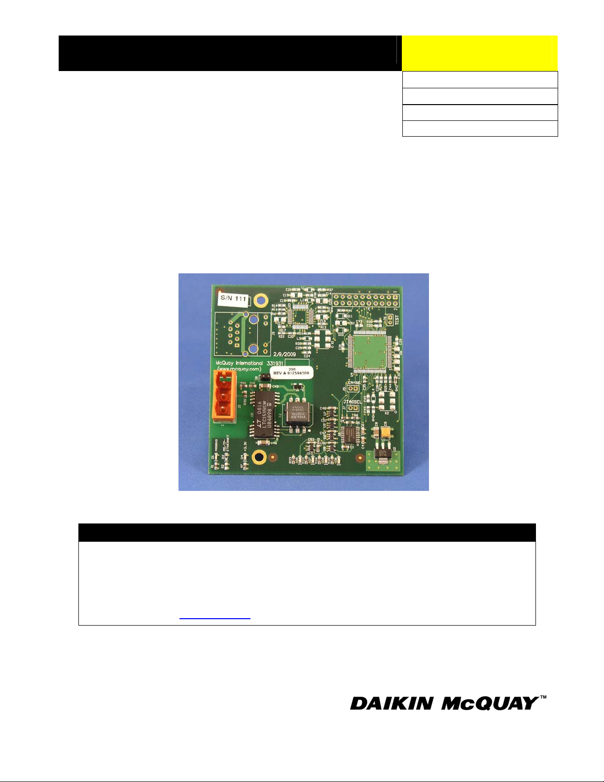
Figure 1 shows the Modbus Communication Module, located on the far left-hand side of the image
below. Figure 2 shows the important features of the Modbus Communication Module, which include
the LED locations and network connection.
Figure 1. Modbus Communication Module Attached to the Magnitude Chiller I/O Backplane
Modbus communication
module (attached)
5 IM 993-1
Page 6

D1
D4
J8 Jumper
D5
D7
D9
D8
Figure 2. Modbus Communication Module Major Components
Network Connector
Common
+
-
Light Emitting Diodes (LEDs)
The Modbus Communication Module has six LEDs to indicate communication activity and data
transmission status. These indicators are visible when the communication module is connected to the
Magnitude Chiller I/O Backplane and the unit is powered o n. See Figure 2 for LED locations and
Table 1 for a description of LED activity.
Table 1. Description of LED Activity
LED Color Meaning
D1 Green Communication module supports a Modbus network. If
present, this LED will always be lit when 5VDC power
(supplied from the chiller unit controller) is present.
D4 Yellow Indicates local 3.3 VDC power is present.
D5 Yellow Flashes when the communication module transmits data to
the chiller unit controller.
D7 Green Flashes when the communication module receives data from
the chiller unit controller.
D8 Green Flashes when the communication module receives data from
the Modbus network.
D9 Yellow Flashes when the communication module transmits data to
the Modbus network.
6 IM 993-1
Page 7

Modbus Network Connector
An RS-485 connector connects the Modbus Communication Module to the Modbus network and has
three pins: + ,
-, and Common. See Figure 2 for location.
J8 Jumper
The Modbus Communication Module has a built-in terminating resistor labeled “J8” on the circuit
board. The communication module ships with the jumper installed, providing 120 Ohms of end-ofline resistance to the network. Typically, a network is terminated at each end of each segment.
However, it is the responsibility of the system installer/integrator to recommend whether or not to
terminate a device within the network. If the device does not require terminating resistance, or if an
external terminating resistor is used, the jumper on J8 should be removed. See Figure 2 for location.
7 IM 993-1
Page 8

Installation
The following section describes how to field install a new Modbus Communication Module or
replace an existing Modbus Communication Module on the Magnitude Chiller I/O backplane (i.e.
unit controller main circuit board) so that it can be incorporated into the Modbus network.
!
CAUTION
Electrostatic discharge hazard. Can cause equipment damage.
This equipment contains sensitive electronic components that may be damaged by
electrostatic discharge from your hands. Before you handle a communications module, you
need to touch a grounded object, such as the metal enclosure, in order to discharge the
electrostatic potential in your body.
Contents of the Modbus Communication Module Kit
The following is the list of items included in the field-installed kit:
The Modbus Communication Module
Network connector (attached to communication module)
Two screws
Installation Manual (IM 993)
Installing a new Modbus Communication Module
Follow these steps to install a new Modbus Communication Module on the Magnitude Chiller I/O
backplane.
! WARNING
Electric shock hazard. Can cause personal injury or equipment damage.
This equipment must be properly grounded. Only personnel knowledgeable in the operation of the
equipment being controlled must perform connections and service to the unit controller.
1. Remove power from the Magnitude Chiller Unit Controller.
2. Connect the Modbus Communication Module to the upper left corner of the chiller I/O
backplane, in the area labeled BAS Interface Board (see Figure 1). Carefully align the holes on
the communication module with the two standoffs attached to the chiller I/O backplane.
!
CAUTION
Carefully align the holes on the communication module with the standoffs on the chiller
I/O backplane
Powering up the controller with the communication module installed upside down can cause
damage to the communication module.
3. Using the two screws that came with the communication module kit, attach the communication
module to the standoffs located on the chiller I/O backplane.
4. Connect the communication module to the network (see Figure 2 for location of network
connection).
5. Apply power to the unit controller.
8 IM 993-1
Page 9

Replacing an Existing Modbus Communication Module
Follow these steps to remove an existing Modbus Communication Module from the chiller I/O
backplane and replace it with a new Modbus Communication Module.
! WARNING
Electric shock hazard. Can cause personal injury or equipment damage.
This equipment must be properly grounded. Only personnel knowledgeable in the operation of the
equipment being controlled must perform connections and service to the Magnitude Chiller Unit
Controller.
1. Remove power from the unit controller.
2. Locate the communication module. It is situated at the upper left corner of the chiller I/O
3. Remove the network cable connector from the communication module.
4. Remove the two screws holding the communication module in place.
5. Grasp the communication module and carefully pull it from the chiller I/O backplane.
6. Install the new communication module (see Steps 1-3 from previous section).
7. Re-attach the two screws to secure the communication module to the chiller I/O backplane.
8. Insert the network cable connector into the communication module.
9. Apply power to the unit controller.
backplane (see Figure 1).
9 IM 993-1
Page 10

Integration
Once the Modbus Communication Module has been properly installed on the unit controller, it is
then possible to integrate the unit controller into a building auto mation system (BAS) via the Modbus
network. The configuration process is described in the following section.
Connecting to the Network
Modbus Network Topology
Standard Modbus network rules apply. The network is a daisy-chain of devices, including all slaves
and the master. The Magnitude Chiller Unit Controller with corresponding communication module is
considered a slave, and as such, can only respond to requests. The Modbus standard recommends
that the network be terminated on each end with the characteristic impedance of the network (about
120 ohms). It is the responsibility of the system installer/integrator to determine whether or not to
terminate a device within the network.
The Modbus Communication Module has a built-in terminating resistor labeled “J8” on the circuit
board. The communication module ships with the jumper installed, providing 120 Ohms of end-ofline resistance to the network (see Figure 2). If the unit controller is not an end-of-line device, or if
the installer is providing an external terminating resistor, the jumper on J8 should be removed.
Follow the guidelines stated in the Modbus specifications (see Reference Documents section for
details).
Configuring the Modbus Communication Module
The Modbus Communication Module can be configured using the Magnitude chiller unit controller
Operator Interface Touch Screen (OITS) display. The unit is ready to operate after you have
configured the parameter values of the unit controller for your particular network. Refer to the
Magnitude Chiller Operation and Maintenance Manual (OM 1034) for default values and unit
controller OITS operating instructions. Refer to McQuay Protocol Document ED 15118 for
descriptions of all the available Modbus variables.
Figures 3 and 4 show the chiller unit controller OITS display screens with the corresponding network
parameters available for configuration. These two screens (BAS1 and BAS2) are accessed by
clicking on the BAS button at the top of the right-hand column .
Modbus Addressing
The Network Address of the Magnitude chiller unit controller must be set via the unit controller
OITS display. The Modbus network address and data transmission rate (Baud Rate) is only available
in the OITS display.
Note: Refer to the Magnitude Chiller Operation and Maintenance Manual (OM 1034) for details
regarding accessing and using the unit controller OITS display.
Configuring the Modbus Communication Module using the OITS Display
1. Open the Magnitude chiller unit controller OITS display screen.
2. Press the SET button, located at the bottom of the screen.
3. Press the BAS button from the top of the column on the right-hand side of the screen.
4. Press the 1 button, located to the right of the BAS Network Protocol field. The BAS Network
Protocol field should now be highlighted (see Figure 3).
5. Press the Change button.
6. If prompted, enter the password 100 and press Enter. Otherwise, proceed to step 7.
7. Press the Change button.
8. Select Modbus from the drop-down menu.
10 IM 993-1
Page 11

9. Press the Enter button.
10. Press the BAS button to access BAS Screen 2 (BAS2).
11. Set the Modbus Network Address (or ident number) within the valid range of 1-247. See Figure
3.
12. Set the desired baud rate for the unit controller (see next section, Setting the Modbus Data
Transmission Rate, for details).
13. Modify the remaining Modbus parameters as necessary. See Table 2 for a complete list.
14. Cycle power to the unit controller.
Setting the Modbus Data Transmission Rate
Modbus baud rate options (in bps) include: 2400, 4800, 9600 and 19200. The factory default baud
rate is 19200 bps. Follow the steps below to change the baud rate for desired network speed via the
OITS display:
1. If you are at the BAS2 screen, proceed to Step 4 (see Figure 4).
2. If you are on the BAS1 screen, press the BAS button and proceed to Step 4.
3. Press the SET button once and then press the BAS button twice.
4. Press the 8 button, located to the right of the MODBUS-Baud Rate field. The MODBUS-
Baud Rate field should now be highlighted.
5. Press the Change button.
6. If prompted, enter the password 100 and press Enter. Otherwise, proceed to step 6.
7. Press the Change button.
8. Press the desired baud rate from the drop-down menu.
9. Press the Enter button.
10. Cycle power to the unit controller.
Figure 3. OITS Display of Network Parameters – BAS1
11 IM 993-1
Page 12

Figure 4. OITS Display of Network Parameters – BAS2
Configurable Parameters
Table 2 defines the Modbus Communication Module network parameters that are configurable via
the unit controller OITS display. Additional parameters are configurable from the Building
Automation System (BAS). For a complete list of available Modbus points, refer to the Magnitude
Chiller Unit Controller - Modbus Protocol Document, ED15118 (available on www.mcquay.com).
At a minimum, you must set the following before establishing network communication between the
unit controller and the BAS:
1. BAS Network Protocol
2. Network Address (ident number)
3. Verify the correct baud rate and change if necessary
Additional Modbus network parameters are shown below in Table 2.
Table 2. Network Configuration Menu
Parameter Value (Range)/Definition Initial Value/Note
BAS Network Protocol None-Modbus-LONWORKS-BACnet IP-
BACnet Ethernet-BACnet MS/TP/This
point defines the protocol being used.
Modbus - Baud Rate 1200-2400-4800-9600-19200/Data
transfer speed (bps).
Modbus – Network Address 1-247/The Modbus Address of the
communication module.
Modbus – English / Metric English-Metric/Defines whether the data
passed from the controller is passed in
English or Metric units.
None/Set this value to Modbus. Cycle
power to the unit controller after changing
this parameter.
19200/Cycle power to the unit controller
after changing this parameter.
1/This must be unique throughout the entire
Modbus network.
English/Changes to this parameter take
effect immediately in the unit controller.
Note: If unit controller application software requires uploading in the field, the network
configuration parameters revert to their default values. Please contact the Technical
Response Center at 877-349-7782 for assistance with upgrading unit controller application
software.
12 IM 993-1
Page 13

Service Information
Test Procedures
If you can control the unit from the OITS display, but you are not able to communicate with unit via
the network, follows these steps:
Check the network wiring
Check the network parameters and verify that they are correct and that there are no
duplicate devices on the network
Verify BAS Network Protocol is set correctly. Cycle power after changing this parameter.
Check communications (see Table 1 for description of communication module LED
activity).
If the Modbus Communication Module still does not respond, contact the McQuay Controls
Customer Support Group at 866-4MCQUAY (866-462-7829).
Parts List
Installation Kit
Description Part Number
Modbus Communication Module kit (kit includes communication
module, two screws, and Installation Manual, IM 993)
332356903
This document contains the most current product information as of this printing. For the most current product
information, please go to www.mcquay.com
Terms and Conditions of Sale and Limited Product Warranty.
13 IM 993-1
. All McQuay equipment is sold pursuant to McQuay’s Standard
 Loading...