

Page 1
Installation Manua l
Supersedes: February 2012
STARTER
COMPRESSOR
OIL PUMP
UNIT
CONTROLLER
EVAPORATOR
CONDENSER
SUPPORT
IM 1128-1
WSC, WME and WMC-B Centrifugal Chillers
Reassembly of Knockdown Shi pm e nts
Group: Chiller
Part Number: 331375601
Effective: April 2012
REV: 01
Page 2
!
DANGER
!
WARNING
!
CAUTION
Table of Contents
WSC Chiller Introduction ............................................................................... 3
Type I Reassembly ............................................................................................ 5
Type II Reassembly ........................................................................................ 14
Unit Photographs ................................................................................................................. 26
Type III Reassembly ....................................................................................... 28
Field Insulation Guide ................................................................................... 29
Dimensions and Weights ................................................................................ 31
Type I ................................................................................................................................... 31
Type II ................................................................................................................................. 33
Shipping Lists ................................................................................................. 38
WMC-B Introduction ..................................................................................... 42
Type IV Disassembly-Reassembly....................................................................................... 43
Ty pe V Disassembly-Reassembly ........................................................................................ 43
WME Introduction ......................................................................................... 51
Type I Reassembly .......................................................................................... 52
Type II Reassembly ........................................................................................ 53
Type III Reassembly ....................................................................................... 56
Knockdown Dimensions ...................................................................................................... 57
Piping Removal ................................................................................................................... 58
Compressor Removal and Re-Attachment ........................................................................... 63
Compressor Removal and Re-Attachment ........................................................................... 64
Recognize Safety Symbols, Words, and Labels
The following label is used in this manual to indicate immediate or potential hazards. It is the
responsibility of the owner and i nst all er t o read a nd comply with all safet y information and inst ruct ions
accompanying these symbols. Improper installation, operation and maintenance can void the warranty.
Dangers indicate a hazardous situation which will result in death or serious injury if not
avoided.
Warnings indicate potentially hazardous situations, which can result in property damage,
severe personal injury, or death if not avoided.
Cautions indicate potentially hazardous situations, which can result in personal injury or
equipment damage if not avoided.
©2012 McQuay International. Illustrations and data cover the McQuay International product at the time of publication and we
reserve the right to make changes in design and construction at anytime without notice.
™® The following are trademarks or registered trademarks of their respective companies: Magnitude, MicroTech E, from
McQuay Internation al, Victaulic from Victaulic Company
2 Field Installation Procedure IM 1128-1
Page 3

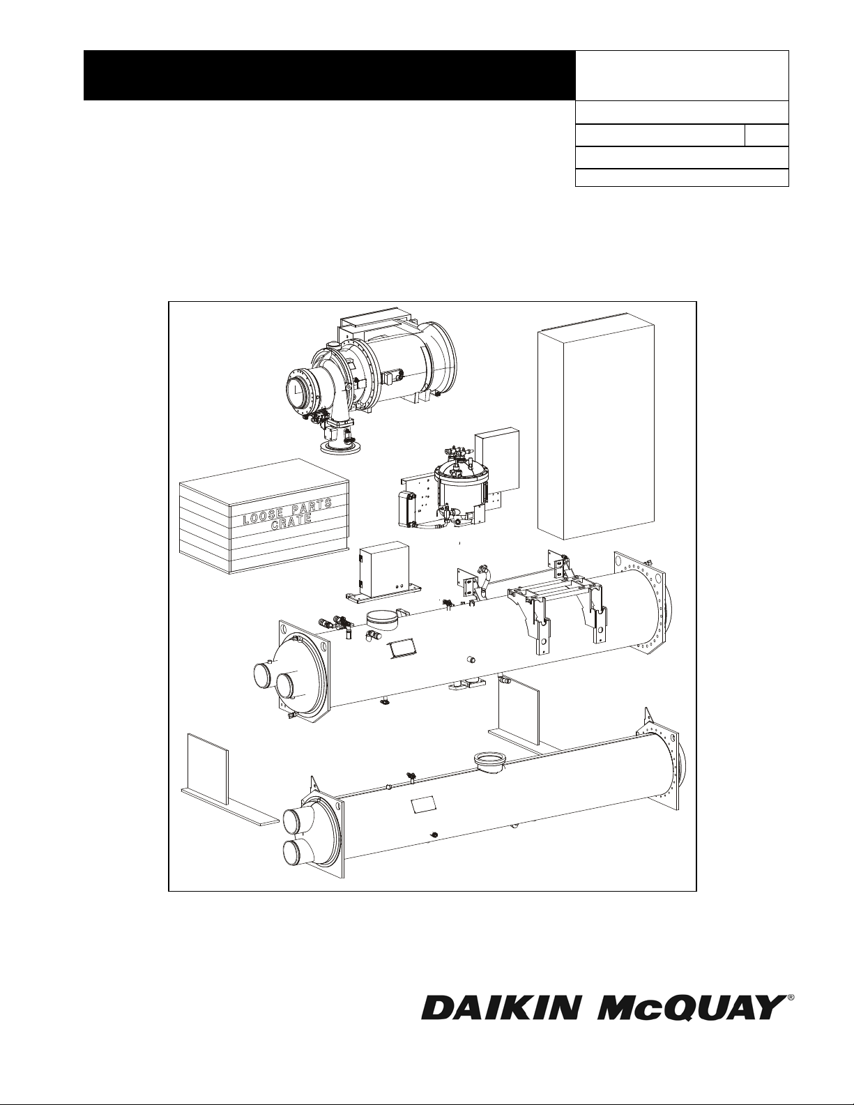
WSC Chiller Introduction
It is estimated that fifty percent of retrofit applications require partial or complete disassembly of the
chiller. Daikin McQuay offers three solutions to the disassembly and reassembly effort on Model
WSC, single compressor centrifugal chillers.
TYPE I: The compressor is removed and put on a skid. All associated wiring and piping possible will
remain on the vessel stack. The remaining loose parts will be packaged in a separate crate.
1. Block-offs will cover all openings on the compressor and vessels.
2. The compressor and vessels will receive a 5-psi helium holding charge.
3. The compressor will not be insulated at the factory. An insulation kit will be shipped with the unit.
4. The starter will ship loose. Bracket and cable kit to be included for unit-mounted starters and/or
cableway for mini-cabinet starters.
5. The evaporator will be insulated at the factory.
6. Refrigerant will not be shipped with the unit and must be secured locally and furnished and
installed by the installer.
7. Lubricant will be shipped in containers from the factory for field installation.
8. All field piping connections will be Victaulic, O-ring face seal or copper brazing.
9. All free piping ends will be capped.
10. Touch-up paint will be included.
11. The unit will undergo the rigorous, full Daikin McQuay test program at the factory.
12. Contact local McQuay Factory Service for pricing and scheduling of required installation
supervision.
TYPE II: The compressor with its terminal box is removed and placed on a skid. The condenser,
evaporator, oil pump, oil cooler and tube sheet supports will remain connected only by their attachment
bolts, ready for field disassembly and reassembly in the building. All wiring and piping that
interconnects the components will be removed. The loose parts will be packaged in a separate crate.
1. Block-offs will cover all openings on the compressor and vessels.
2. The compressor and vessels have a 5-psi helium holding charge.
3. The compressor will not be insulated at the factory. An insulation kit will be shipped with the unit
and will also include a container of adhesive.
4. Only the evaporator shell will be factory insulated. Loose insulation will be shipped for the
suction line and remaining surface areas.
5. The starter will ship loose.
6. Refrigerant will not be shipped with the unit and must be secured locally and furnished and
installed by the installer.
7. Lubricant will be shipped in containers from the factory for field installation.
8. All field piping connections will be Victaulic, flanged, O-ring face seal or copper brazing.
9. Bracket and cable kit will be included for all unit-mounted starters and/or cableway for mini-
cabinet starters.
10. All free piping ends will be capped.
11. Touch-up paint and stick-on wire ties will be included.
12. A bolted bracket instead of a weld will mount the oil pump.
13. The discharge piping assembly will have a bolted flange connection (instead of welded) at the
condenser. This assembly will ship loose.
14. Piping that remains attached to a component will be supported if it is not rigid.
15. The chiller will not be run-tested at the factory but the compressor, oil pump assembly and heat
exchangers will be tested as sub-assemblies.
IM 1128-1 Field Installation Procedure 3
Page 4
16. The control panels are shipped separately but have all sensors wired in, labeled and tied up.
Matching labels will exist at the sensor connection on the unit.
17. Contact local McQuay Factory Service for pricing and scheduling of required installation
supervision.
TYPE III: The uni t ships fully assembled and is field ready to knockdown. Included are the vessel
bolt-on connection brackets, the discharge stack bolt-on flanges at the condenser and the bolt-on oil
pump assembly.
1. The unit is shipped fully charged with refrigerant and lubricant.
2. The unit will be factory insulated and painted.
3. All electrical and sensor wiring will be fastened as usual.
4. The starter will ship per order instructions.
5. Touch up paint and stick-on wire ties will be included.
6. This unit will be fully tested at the factory.
7. Labels will be provided with the instructions to mark piping, electrical wiring and sensor wiring.
NOTE: If disassembly involves breaking any refrigerant connection, the refrigerant charge must be
pumped down and isolated in the condenser.
Typical WSC Centrifugal Chiller
4 Field Installation Procedure IM 1128-1
Page 5

Type I Reassembly
!
WARNING
Description
TYPE I: The compressor with its terminal box is removed and placed on a skid as a separate package.
The suction piping is removed and shipped loose. All other piping will be disconnected from the
compressor and remain attached to the vessel stack, where possible. Wiring and sensors to the
compressor will be disconnect ed, rolled up and tied to the control pane ls. The remaining loose parts
will be packaged in a separate crate.
1. Block-offs will cover all openings on the compressor and vessels.
2. The compressor and vessels will receive a 5-psi helium holding charge.
3. The compressor will not be insulated at the factory. An insulation kit will be shipped with the unit
and will also include a container of adhesive.
4. The unit vessel stack will be insulated at the factory.
5. This unit will be tested with a full refrigerant charge at the factory and the charge will be removed
after testing.
6. Refrigerant will not be shipped with the unit and must be secured locally and furnished and
installed by the installer.
7. Bracket and cable kit will be included for all unit-mounted starters and/or cableway for mini-
cabinet starters.
8. All free piping ends will be capped.
9. Touch-up paint and stick-on wire ties will be included.
10. Lubricant will be shipped in containers from the factory.
11. The starter will ship loose.
12. All field piping connections will be Victaulic, flanged, O-ring face seal or copper brazing.
13. The unit control panel and compressor control panel will be attached to the unit with loose sensor
wires tied up behind the panel.
Reassembly Steps
NOTE: Additional instructions may be shown on the assembly drawings.
1. Mount the compressor on the stack. Be careful to avoid damaging lines already mounted on the unit.
Mounting bolts, washers and nuts are shipped loose. Leave the mounting bolts loose until the suction
and discharge lines are installed and aligned.
During assembly, bolts holding block-off plates (motor cooling connection, for example), are used for
reassembly of the component. See Figure 1 or Figure 2 for the location and description of the blockoffs.
2. Do not remove block-offs until ready to install piping. The compressor and vessels have a Schrader
valve on their block-off plates to be used for relieving the helium holding charge.
Remove compressor and vessel holding charge through the Schrader valve in the block-off plates
before attempting to loosen any fittings on them. Failure to do so can cause severe bodily injury.
3. Install the suction and discharge piping (see Figure 3). Before tightening the Victaulic couplings,
position the suction and discharge piping so that the compressor can be aligned to give the best fit-up.
When this is achieved, secure the compressor mounting bolts and proceed with installing the Victaulic
couplings using a light coating of Victaulic lubrication.
IM 1128-1 Field Installation Procedure 5
Page 6

4. Install the liquid injection line (see Figure 4). The liquid injection line is attached to the condenser
and has shipping straps securing it to the evaporator and condenser. It, and the compressor, each have
a block-off. Note that any given injection line may be configured somewhat differently than shown on
the drawing.
5. Install the motor cooling line (see Figure 5) using the same procedure as the liquid injection line.
6. Install the motor drain line (see Figure 6) using the same procedure as the liquid injection line.
7. Piping for the optional hot gas bypass is shipped mounted on the unit except for models WSC100,
WSC113 and WSC126 with vessel stacks sizes E36C30, E36C36, E42C36, E42C42, E48C42 and
E48C48. These units have the piping assembly shipped loose for field mounting. See Figure 7.
8. Install the compressor lubrication lines. There are four lines as shown in Figure 8:
a. Thrust pump return, injects lubricant from the compressor thrust pump (thrust bearing) into
the lubricant supply line.
b. Oil drain, drains lubricant from the compressor to the sump.
c. Vent line, vents refrigerant from the sump back to the compressor suction.
d. Oil supply, supplies lubricant from the pump in the sump to the compressor.
There is a variety of fitting types employed on the oil lines. Reconnect the compression fittings, bolt
on the flanges using new gaskets furnished, and re-sweat the sweat connections.
9. Install the four-way solenoid on the compressor suction housing.
10. Install compressor wiring using Figure 9 (including notes) as a guide. Figure 9 shows connections for
both Type I and Type II arrangements. Only the connections listed below are required to be made for
Type I. The wire end that has been disconnected, and its attachment point on the compressor, will
each have a label attached (VC for the vane close switch, for example) for matching purposes.
a. Guardistor, G1 (and G2 on some units), terminal box located on side of motor housing.
b. Compressor heaters, CP1 (and CP2 on some units), located on the bottom of the compressor.
c. Vane load/unload solenoids, SA and SB, located on the four-way solenoid assembly.
d. Vane close switch, VC, located on compressor next to the discharge housing.
e. Vane open switch, VO, located on suction end of compressor.
f. High pressure switch, HPS, located on compressor discharge nozzle.
11. If the unit has been ordered with a starter or VFD as unit mounted, brackets for mounting it and
interconnection cables to the compressor motor will be included as ship loose items. Control wiring as
shown in Figure 9 and Figure 13 (field wiring diagram), will also be required. The field wiring
diagram located on the control panel door should also be consulted as it will be current. If the unit has
a free standing starter, use normal field procedures for mounting and wiring.
Normal procedure of leak testing, triple evacuation, and charging with refrigerant and lubricant must
be followed prior to the start up procedure.
12. Insulate the compressor motor, suction line, and other miscellaneous areas with the included insulation
and adhesive after leak testing. See Field Insulation Guide on page 29.
This completes the reassembly procedure.
6 Field Installation Procedure IM 1128-1
Page 7
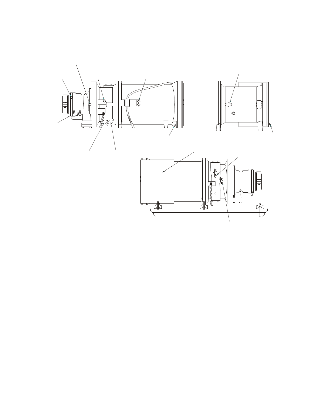
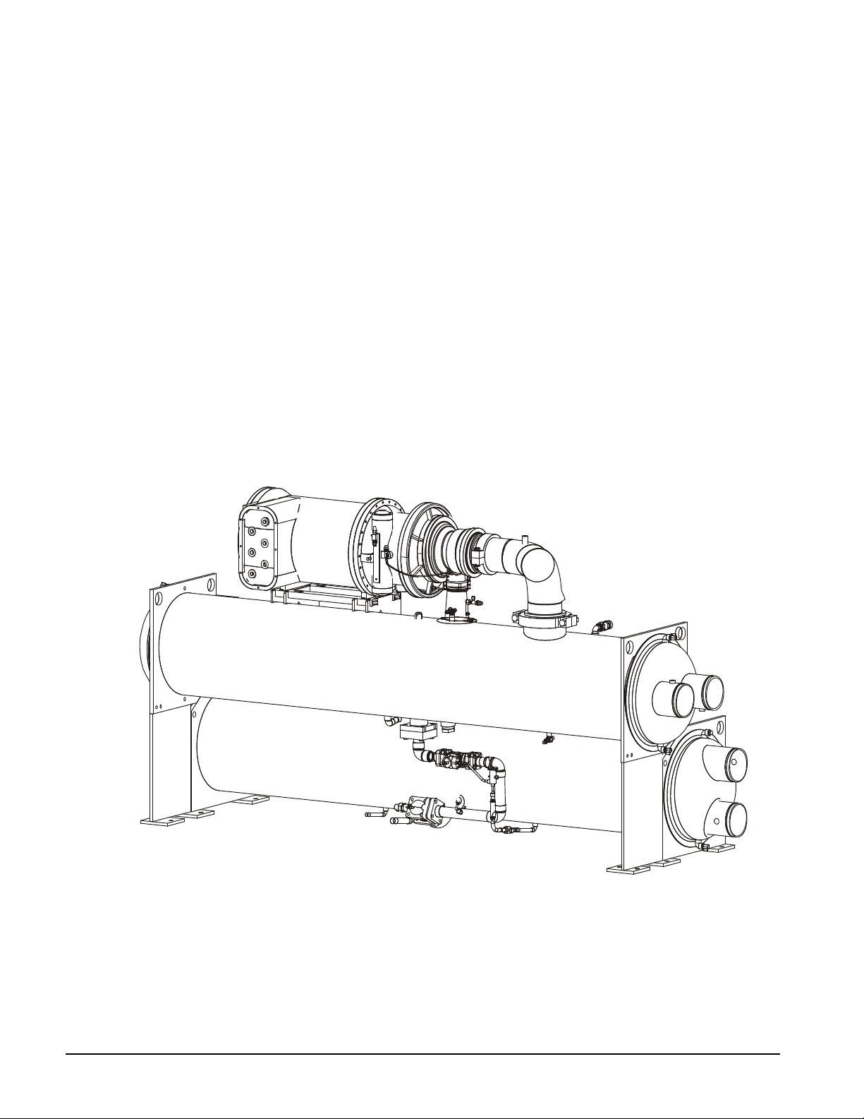
Figure 1, WSC 063 - 087 Compressor Connections
RIGHT VIEW
R331311301C0100
15" MTR. HSG.
LEFT VIEW
(20" MTR.HSG.)
MOTOR COOLING
REFRIGERANT
FROM COND. BTM
OIL LINE VENT
FROM TOP FRONT
OF OIL PUMP
ATT ACH TAG TO ONE
TERMINAL INSIDE BOX
4-WAY SOLENOID VALVE
LIQUID
INJECTION
FROM COND. BTM.
OIL THRUST RETURN
TO OIL LINE TEE
OIL DRAIN
TO TOP BACK
OF OIL PUMP
MOTOR DRAIN
TO EVAP BOTTOM
MOTOR DRAIN
OIL OUT TO SA AND SB
SOLENOID VALVES AND
MOTOR DRAIN
TO EVAP BOTTOM
MOTOR COOLING
FROM COND. BTM.
OIL SUPPLY
FROM OIL COOLER
Notes:
1. New O-rings and gaskets are in a plastic bag.
2. Compressor is charged with 5-psi of helium.
IM 1128-1 Field Installation Procedure 7
Page 8
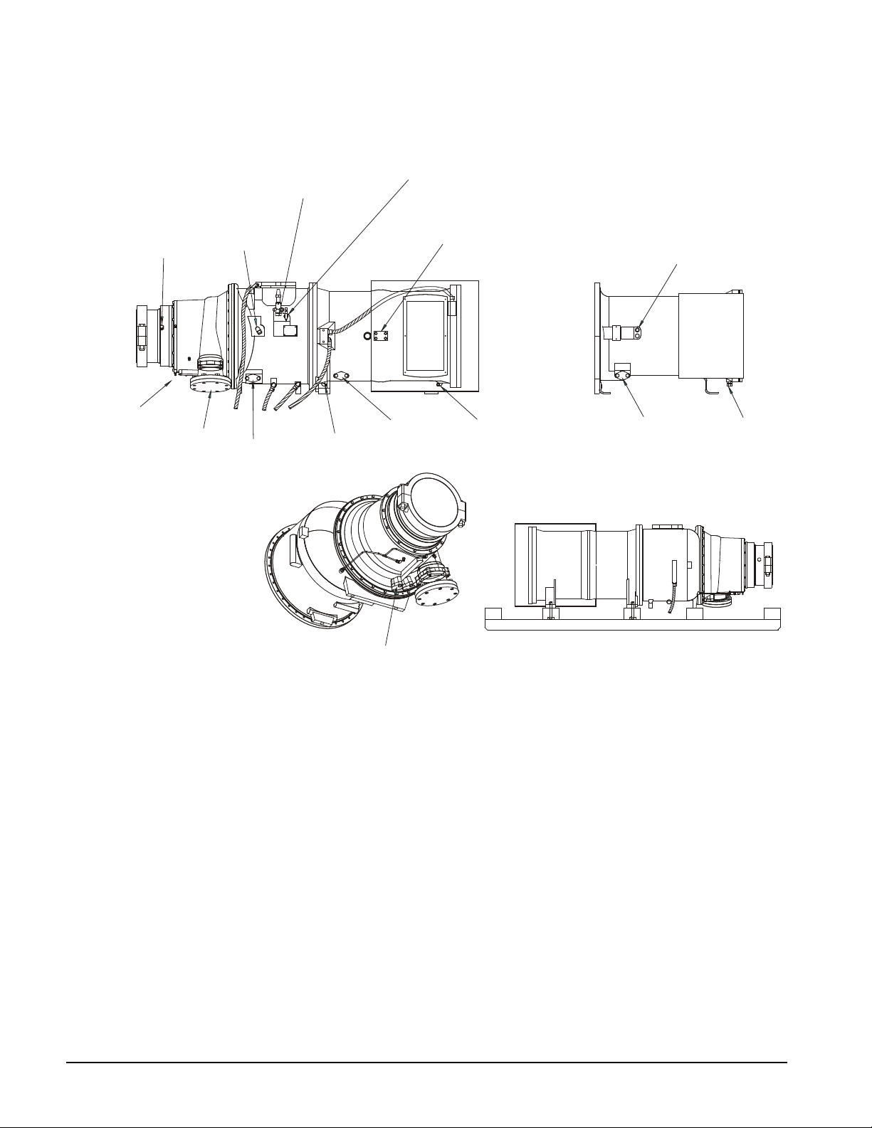
Figure 2, WSC 100-126 Compressor Connections
LEFT VIEW
(22" MTR. HSG.)
20" MTR. HSG.
RIGHT VIEW
BOTTOM VIEW
OIL VENT
OIL SUPPLY
MOTOR COOLING
OIL DRAIN
DISCHARGE
BLOCKOFF
REF. DRAIN
REF.DRAIN
REF. DRAIN
MOTOR COOLING
MOTOR DRAIN
MOTOR DRAIN
LIQUID INJECTION
UNSWEAT LINE AND
SHUT VALVE
FROM TOP FRT.
OF OIL PUMP
FROM CONDENSER
BOTTOM
TO TOP BACK
OF OIL PUMP
TO EVAP.
BOTTOM
TO EVAP.
BOTTOM
TO EVAP.
BOTTOM
TO EVAP.
BOTTOM
TO EVAP.
BOTTOM
FROM COND.
BOTTOM
FROM COND. BOTTOM
4 WAY SOLENOID VALVE
OIL THRUST
RETURN TO
OIL LINE TEE
TO OIL COOLER
R331311301D0200
OIL OUT TO SA AND SB
SOLENOID VAL VES AND
OIL PRESSURE TRANSDUCER
Notes:
1. New O-rings and gaskets are in a plastic bag.
2. Compressor is charged with 5-psi of helium.
8 Field Installation Procedure IM 1128-1
Page 9
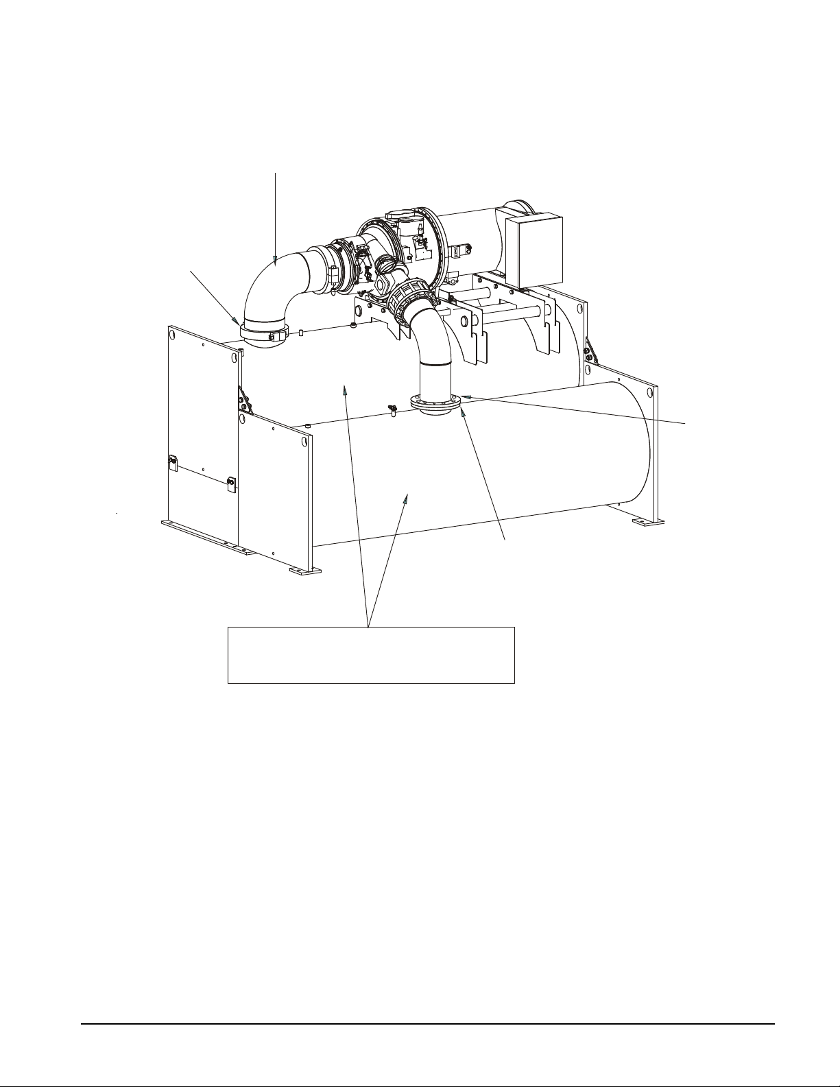
Figure 3, Suction and Discharge Piping
R331311308C0100
BOLT-ON
BLOCKOFF PLATE
TYPE II
UNITS RECEIVE
SLIP-ON ASME
FLANGES
TYPES II & III
TYPES I & II
TYPES I & II
VICTAULIC
BLOCKOFF PLATE
INSTALL SUCTION
PIPING
EVAPORATOR AND CONDENSER ARE EVACUATED
AND CHARGED WITH 30 PSI OF HELIUM.
TYPES I & II
IM 1128-1 Field Installation Procedure 9
Page 10
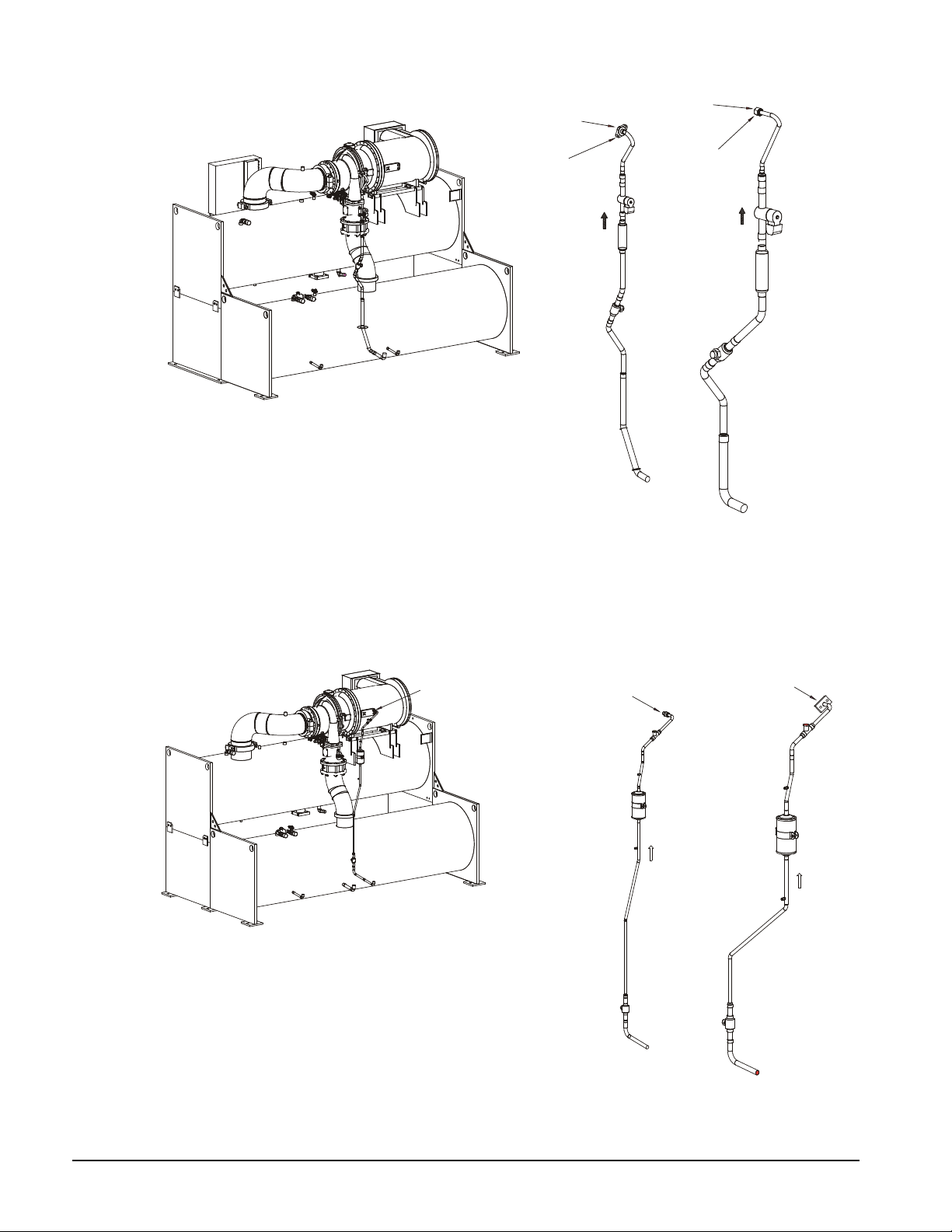
Figure 4, Liquid Injecti on Li nes
MECHANICAL
TORQUE TO
58 FT/LBS
R331311304C0100
MECHANICAL
BREAK POINT
MECHANICAL
BREAK POINT
MOTOR COOLING LINES
(NOT ALL VARIA TIONS SHOWN)
TYPE I
BLOCKOFF
TYPE I
BLOCKOFF
BREAK POINT
TYPE I
BLOCKOFF
R331311303C0100
MECHANICAL
BREAK POINT
TYPE I
BLOCKOFF
LIQUID INJECTION LINES
(NOT ALL VARIATIONS SHOWN)
NOTE:
The liquid injection line (above) and the motor c ooling line (below) are attached to the condenser and have
shipping straps securing them to the evaporator and condenser. The lines and the compressor, each have blockoff plates, resulting in extra bolts.
Figure 5, Motor Cooling Lines
10 Field Installation Procedure IM 1128-1
Page 11
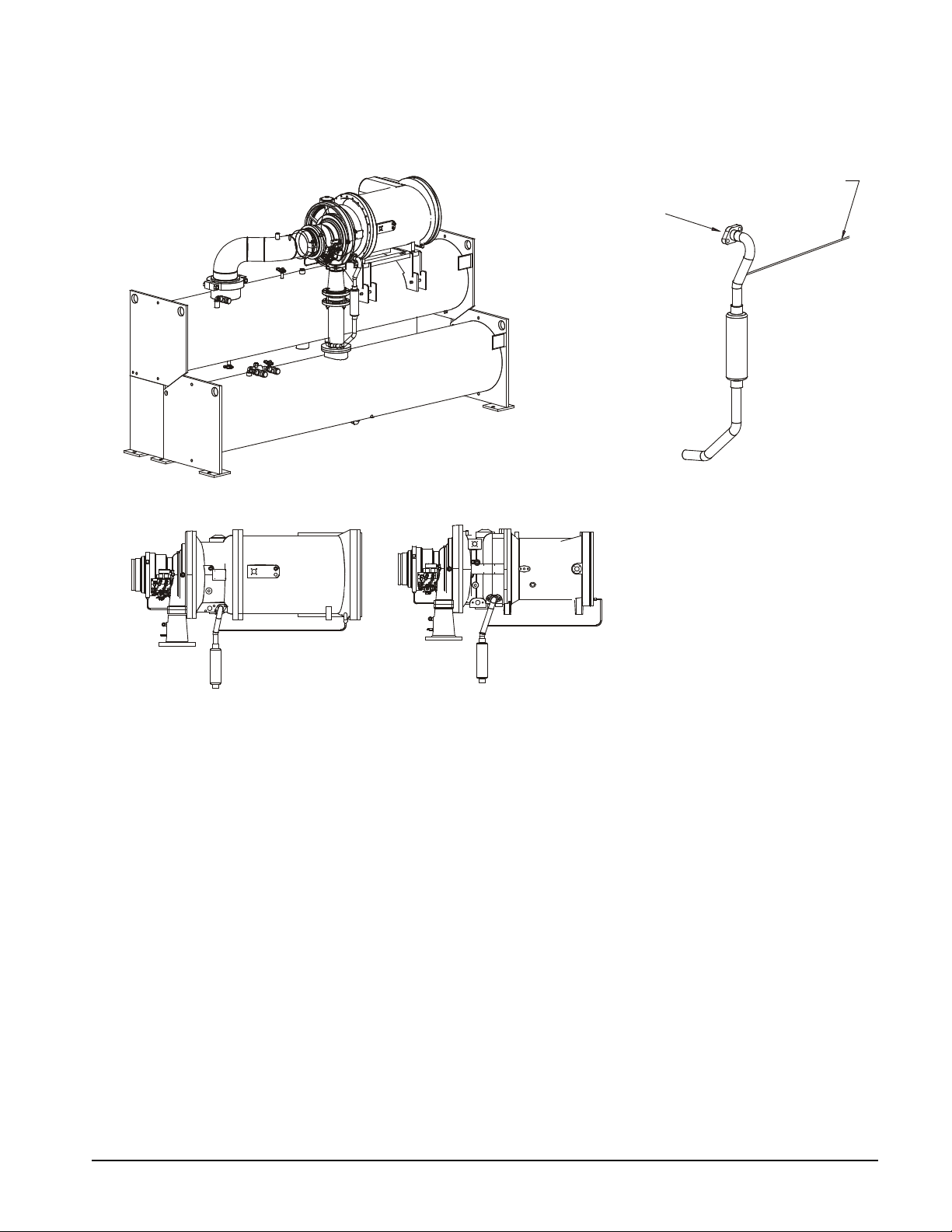
Figure 6, Motor Drain Line
R331311305C0100
20" MOTOR REF. DRAIN
CONNECTION
(REAR VIEW)
15" MOTOR REF. DRAIN
CONNECTION
(REAR VIEW)
MOTOR HOUSING
DRAIN LINE
MOTOR DRAIN LINE
(NOT ALL VARIATIONS SHOWN)
MECHANICAL
BREAK POINT
IM 1128-1 Field Installation Procedure 11
Page 12
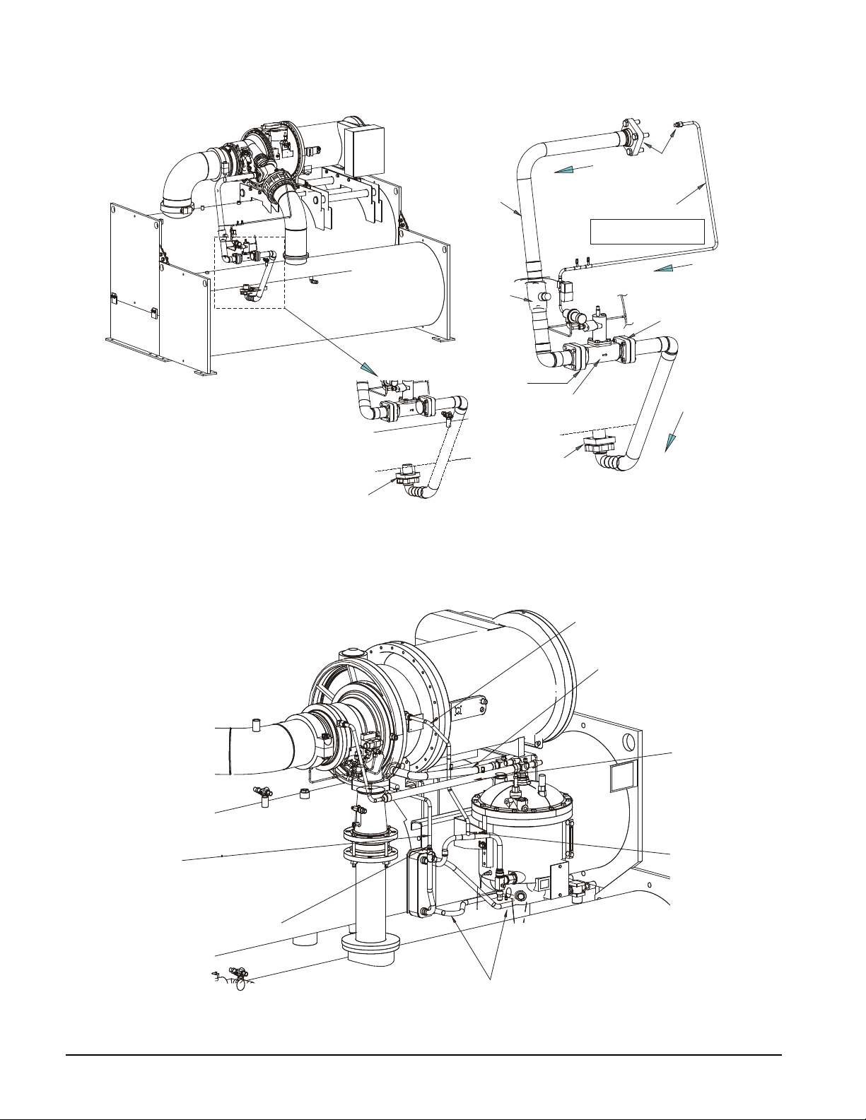
Figure 7, Optional Hot Gas Bypass Piping
R331311307C0100
HOT GAS
BYPASS
LINE
HOT GAS
BYPASS
PILOT
LINE
SHUT OFF
VALVE
EXPANSION
VALVE
CONNECTION TO
DISCHARGE NOZZLE
E
V
A
P
O
R
A
T
OR
B
O
TT
O
M
MECHANICAL
BREAK POINTS
MECHANICAL
BREAK POINT
MECHANICAL
BREAK POINT
MECHANICAL
BREAK POINT
FLOW
FLOW
FLOW
NOTE: THIS LINE IS NOT ALWAYS
PRESENT. SOME UNITS HAVE
ELECTRONIC VAL V ES.
BLOCKOFF
TYPE II UNITS
INSTALL HOT GAS PIPING
TYPE I UNITS
INSTALL HOT GAS PIPING ON WSC MODELS
100, 113, & 126 WITH STACK SIZES
E36C30, E36C36, E42C36, E42C42,
E48C42, E48C48
R331311302C0200
OIL VENT
OF THRUST RETURN LINE
OIL SUPPLY
RESWEAT LINE
ABOVE REDUCER
RESWEAT LINE
ABOVE TEE
TYPES I & II
TYPES I & II
INSTALL T OP PORTION
TYPES I AND II
INSTALL
INSTALL WATER LINES
TYPE II
INSTALL TOP PORTION
OF LINE
TYPES I & II
TYPES I AND II
INSTALL
OIL DRAIN
Figure 8, Oil and Water Lines
12 Field Installation Procedure IM 1128-1
Page 13
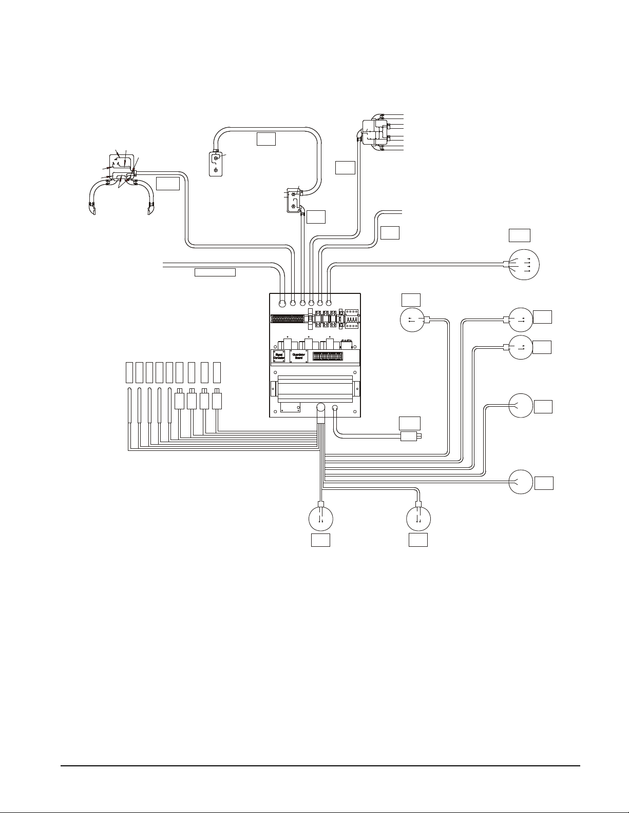
Figure 9, Electrical and Sensors, Compr essor Contr ol Box and Connections
R331311501C0100
N7
N7
155
155
155
154
GUARDISTOR
CONNECT LEAD 155
TO TERMINAL IF 2nd
BOX IS NOT USED.
2nd TERMINAL BOX
USED ON SELECTED
MOTORS.
HIGH
PRESSURE
SWITCH
E9
E7
NUMBER OF HEATERS MAY VARY
DUE TO COMPRESSOR SIZE.
JUNCTION BOX NOT ON ALL UNITS.
SECOND HEATER CABLE FROM COMPR.
ON WSC063-087 ONLY.
}
3
2
1
E4
E6
05
0708
E5
OIL PUMP
HEATERS
{TO STARTER
COMPRESSOR
HEATERS
CS04
CS05
CS07
CS09
CS10
CS06
CS03
CS02
CS01
HOT GAS
SOLENOID
LIQ. INJ.
SOLENOID
OPTION
135
136
133
134
141
142
139
140
132
131
137
138
OIL COOLER
SOLENOID
VANE CONTROL
SOLENOIDS
VANE
CLOSE
SWITCH
146
145
VANE
OPEN
SWITCH
103
104
VFD SPEED
SIGNAL
102
101
(ON VFD ONLY)
LI
HG
VO
VC
SA
SB
OC
VFD
LEAVING EVAP WATER TEMP.
OIL FEED TEMP.
COMPR. DISCHARGE TEMP.
COMPR. SUCTION TEMP.
OIL SUMP TEMP.
COND. PRESS. SENSOR
EVAP. PRESS. SENSOR
OIL FEED PRESS. SENSOR
OIL SUMP PRESS. SENSOR
VANE
LOAD
VANE
UNLOAD
JUNCTION BOX ON COMPRESSOR
MOUNTING BRACKET NEAR THE
SUCTION PIPE.
OPH
G2
G1
CP1
CP2
HPS
COMPRESSOR CONTROL BOX
CCB POWER
10 LEADS 4 LEADS
(ON COMPRESSOR)
(ON VFD)
(ON SUPPLY
WATER LINE)
(ON COMPR.
FRONT)
(ON COMPR. NEXT
TO DISCHARGE)
(ON COMPR.
FRONT)
(ON HOT
GAS LINE)
(ON LIQUID
INJ. LINE)
(ON DISCHARGE
NOZZLE)
Note:
1. Reference compressor controller schematic for detailed wiring connections.
IM 1128-1 Field Installation Procedure 13
Page 14
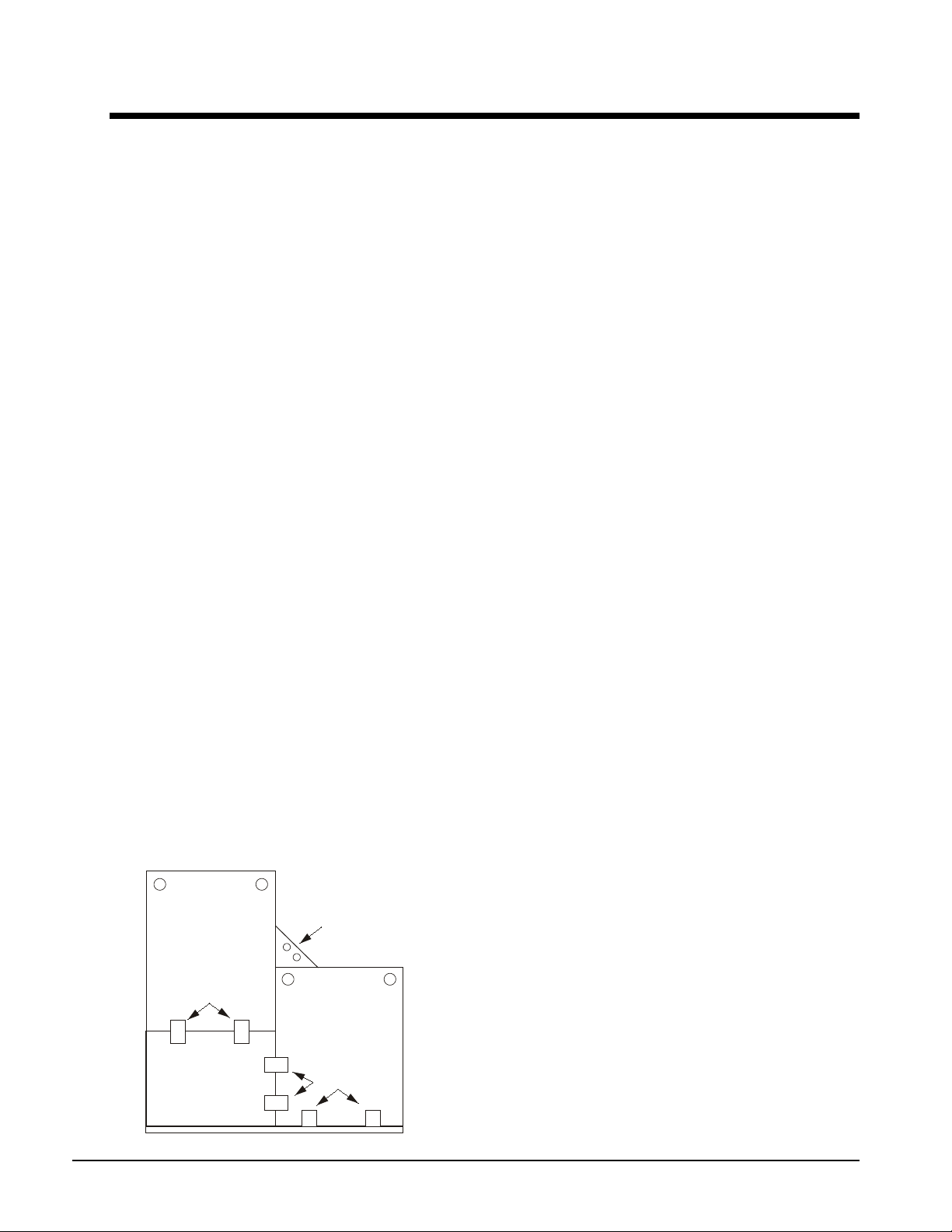
EVAPORATOR
TUBE SHEET
TUBE SHEET
SUPPORT
PLATE
CONDENSER
TUBE SHEET
BOLTED
BOLTED
WELDED
TWO ANGLE PLATES,
ONE WELDED TO EVAP.
ONE WELDED TO COND.
THEN BOLTED TOGETHER.
Type II Reassembly
Description
TYPE II: The compressor with its terminal box is removed and shipped on a skid. The condenser,
evaporator, oil sump, oil cooler and tube sheet support plates will remain connected only by their
attachment bolts, ready for field disassembly on site and subsequent r eassembly in the building. All
wiring and piping that interconnects the components will have been removed and will require
reinstallation. The loose parts will be packaged in a separate crate.
1. Block-offs will cover all openings on the compressor and vessels.
2. The compressor and vessels will receive a 5-psi helium holding charge.
3. The compressor will not be insulated at the factory. An insulation kit will be shipped with the unit
and will also include a container of adhesive.
4. Only the evaporator shell will be factory insulated. Loose insulation will be shipped for the
remaining surface areas.
5. The starter will ship loose.
6. The refrigerant will be field supplied.
7. All field piping connections will be Victaulic, flanged, O-ring face seal or copper brazing.
8. Bracket and cable kit will be included for all unit-mounted starters and/or cableway for mini-cabs.
9. All free piping ends will be capped.
10. Touch-up paint and stick-on wire ties will be included.
11. A bolted bracket instead of a weld will mount the oil pump.
12. The discharge piping assembly will have a bolted flange connection (instead of welded) at the
condenser. This assembly will ship loose.
13. Piping that remains attached to a component will be supported if it is not rigid.
14. The chiller will not be run-tested at the factory but the compressor, oil pump assembly and heat
exchangers will be tested as sub-assemblies.
15. The control panels are shipped separately but have all sensors wired in, labeled and tied up.
Matching labels will exist at the sensor connection to the unit.
Reassembly Steps
NOTE: Additional instructions may be shown on the assembly drawings.
The Type II arrangement is shipped with the evaporator, condenser, tube sheet support plate, oil cooler
and oil sump bolted together. This provides structural support during transit and also allows several
options for disassembly.
Figure 10, Component Disassembly
In most cases for narrow entry, the condenser will be
separated by unbolting it from the evaporator angle
bracket and from the tube sheet support plate. This
leaves the evaporator and the support plate that has
the mounting foot extended under where the
condenser used to be. Therefore, the evaporator is
usually unbolted from the two support plates, which
can then be easily handled by themselves.
14 Field Installation Procedure IM 1128-1
Page 15

!
WARNING
Remove compressor and vessel holding charge through the Schrader valve in the block-off plates
before attempting to loosen any fittings on them. Failure to do so can cause severe bodily injury.
1. Disassemble the unit to the e xtent required by the site conditions. Rig the components to their final
location and reassemble them using the fasteners that came with the unit.
2. The compressor and its suction and discha rge piping should be installed on the stack before any other
lines are attached. Mount t he compressor on the stack. Mounting bolts, washers and nuts are shipped
loose. Leave the mounting bolts loose until the suction and discharge lines are in place and aligned.
Install the suction and discharge piping. Before tightening the Victaulic couplings, position the suction
and discharge piping so that the compressor can be aligned to give the best fit-up. When this is
achieved, secure the compressor mounting bolts and proceed with installing the Victaulics using a light
coating of Victaulic lubricant. See Figure 3.
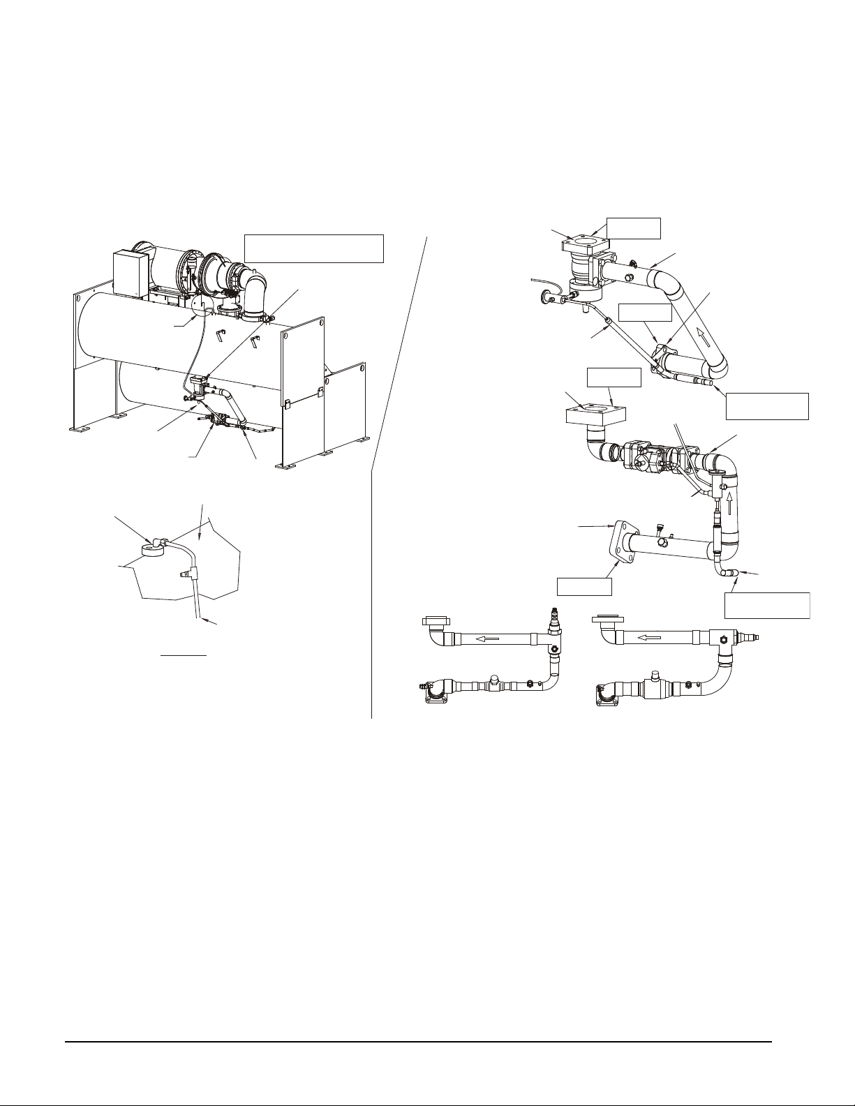
3. Install the liquid line using Figure 11 as a guide. Commonly used arrangements are illustrated. The
bottom two arrangements illustrate lines with electronic valves used on some size units. Due to the
variety of vessel combinations available, variation on specific units will occur.
4. Install the motor cooling line using Figure 5 as a guide.
5. Install the liquid injection line (see Figure 4). Note that any given injection line may be configured
somewhat differently than shown on the drawing.
6. If the oil cool er and oi l sump have been removed on the job site, reinsta ll them using the fasteners tha t
came on the unit. See Figure 12 for piping between the cooler and sump and the cooling water pi ping.
See Figure 8 for the balance of the four oil lines connected to the compressor. There are a variety of
fitting types employed on the oil lines. Reconnect the compression fit tings, bolt on the flanges using
new gaskets/O-rings furnished, and re-sweat the sweat connections.
Due to the wide variety of model arrangements, some or all of the oil piping may be shipped loose.
When possible, the cooler and sump will be shipped mounted to their back plate with as much piping
remaining as possible.
7. Install the four-way solenoid valve assembly on the compressor suction housing.
8. Install the two control panels; the compressor panel is mounted adjacent to the oil sump and the unit
panel is on top of the evaporator. Wire and sensor leads have been disconnected at their terminus and
labeled. They remain connected at the panels and rolled up. Their destinations have matching labels,
which simplifies the installation. Compressor panel sensor labels are prefixed with CS, unit panel labels
with US. Use the following drawings as a guide for installing wiring and sensors:
Compressor panel detail ........................................Figure 18
Unit panel wiring and connections ........................Figure 15
Unit panel detail .....................................................Figure 19
Unit panel sensor locations ....................................Figure 16 and Figure 17
Flow switch wiring detail ......................................Figure 20
9. If the unit has been ordered with a starter or VFD as unit mounted, brackets for mounting it and
interconnection cables to the compressor motor will be i ncluded as shi p loose ite ms. Control wiring as
shown in Figure 9 will also be required. If the unit has a free-standing starter, use normal field
procedures for mounting and wiring.
Normal procedure of leak testing, triple evacuation, and charging with refrigerant and lubricant must be
followed prior to the start up procedure.
IM 1128-1 Field Installation Procedure 15
Page 16
10. Insulate the compressor, suction line, and other miscellaneous areas with the included insulation and
SHOWN IS E36/C36 STACK
WITH 20-INCH MOTOR
R331311306C0100
VIEW B
SEE VIEW B
TOP OF
EVAPORATOR
FROM PILOT
TX VALVE
EVAPORATOR
CONNECTION
CONDENSER
SHUTOFF VALVE
CONNECTION
TO TOP OF
EVAPORATOR
TO TOP OF
EVAPORATOR
EVAPORATOR
CONNECTION
CONDENSER
SHUTOFF VALVE
CONNECTION
FLOW
FLOW
PLUG
EVAP. BLOCKOFF
LIQUID LINES
(NOT ALL
VARIATIONS
SHOWN)
LIQUID
LINES
FLOW
FLOW
(VIEW 'B')
(VIEW 'B')
LIQUID LINE
LIQUID LINE
PILOT LINE
PILOT LINE
RESWEAT PILOT LINE
ABOVE THE SHUTOFF
VALVE
RESWEAT PILOT LINE
ABOVE THE SHUTOFF
VALVE
PILOT LINE
SHUT OFF
VALVE
MECHANICAL
BREAK POINT
MECHANICAL
BREAK POINT
MECHANICAL
BREAK POINT
MECHANICAL
BREAK POINT
CONDENSER
SHUTOFF
VALVE
TYPE II
KNOCKDOWN
ONLY
glue after leak testing. See Field Insulation Guide on page 29.
This completes the reassembly procedure.
Figure 11, Liquid Line Inst allation
NOTE: The bottom two liquid lines show the typical arrangement with electronic expansion valves. Liquid flow can be
in different directions depending on the valve size.
16 Field Installation Procedure IM 1128-1
Page 17
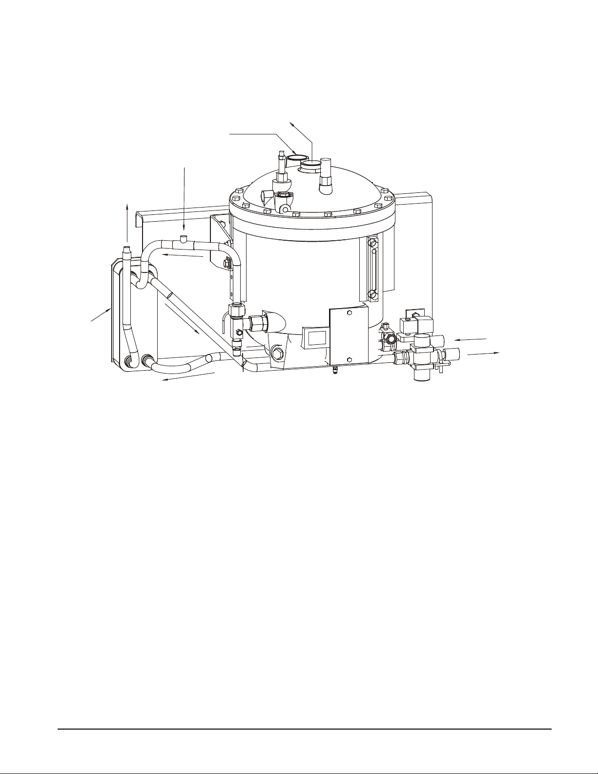
Figure 12, 16 Inch Oil Sump / O il Cooler Assembly
R331311302C0100
F
L
O
W
FLOW
F
LO
W
F
LO
W
PR
E
S
SU
R
E
E
Q
U
A
LI
Z
A
T
I
O
N
PLUG
PLUG
OIL
COOLER
OIL VENT LINE
OIL DRAIN LINE
THRUST RETURN
OIL LINE
FLOW
OIL SUPPLY TO
VALVE ON COMP.
FLOW
FLOW
OIL
SUPPLY
WATER
RETURN
OW
L
F
WATER
SUPPLY
DUE TO DIFFERENT PIPE ROUTINGS
SOME OR ALL PIPING SHOWN MAY
BE SHIPPED LOOSE
ER
T
A
W
Y
PPL
SU
N
R
U
T
E
R
ER
T
A
W
Notes:
1. Piping arrangements will vary according to specific model.
2. Oil sump is shipped without oil on Type I and Type II knockdown units.
3. Type III knockdown units are shipped with oil.
IM 1128-1 Field Installation Procedure 17
Page 18
80
CP2
CP1
H
O
A
C4
H
A
O
C3
H
A
O
79
78
77
74
73
54
CF
86
EF
86
C
25
1
2
11
11
12
22
1
2
6
11
12
22
NOTE 2
NOTE 2
(115V) (24V)
25
55
70
H
A
O
H
A
O
H
O
A
C
H
O
A
C
H
O
A
C
C2
C1
T3-S
PE
L1
L2
CP2
CP1
24
23(5A)
24(5)
23
3
4
3
4
76
75
PE
85
86
81
84
A
82(NO)
83(NC)
POWER
EP2
EP1
L1 L2 L3
GND
T4 T5 T6
T1 T2 T3
T4 T5 T6T1 T2 T3
T1 T2 T3
T3T1 T2
U V W
T4 T3 T5T1 T6 T2
T1 T2 T3
T4 T3 T5T1 T6 T2
GND
LESS
THAN
30V
OR
24VA C
53
71
71
52
1-10 VDC
1-10 VDC
MICROTECH CONTROL
BOX TERMINALS
* COOLING
TOWER
FOURTH
STAGE
STARTER
* COOLING
TOWER
THIRD
STAGE
STARTER
* COOLING
TOWER
SECOND
STAGE
STARTER
* COOLING
TOWER
FIRST
STAGE
STARTER
COOLING TOWER
BYPASS VALVE
COOLING TOWER VFD
ALARM RELAY
(NOTE 4)
MICROTECH
COMPRESSOR CONTROL
BOX TERMINALS
CTB1
-LOAD-
COMPRESSOR
MOTOR
STARTER
(NOTE 1)
115 VAC
STARTER LOAD SIDE TERMINBALS
VFD
STARTER LOAD SIDE TERMINBALS
WYE -DELTA
STARTER LOAD SIDE TERMINBALS
SOLID STATE
STARTER LOAD SIDE TERMINBALS
MEDIUM AND HIGH VOLTAGE
COMPRESSOR TERMINALS
COMPRESSOR TERMINALS
COMPRESSOR TERMINALS
COMPRESSOR TERMINALS
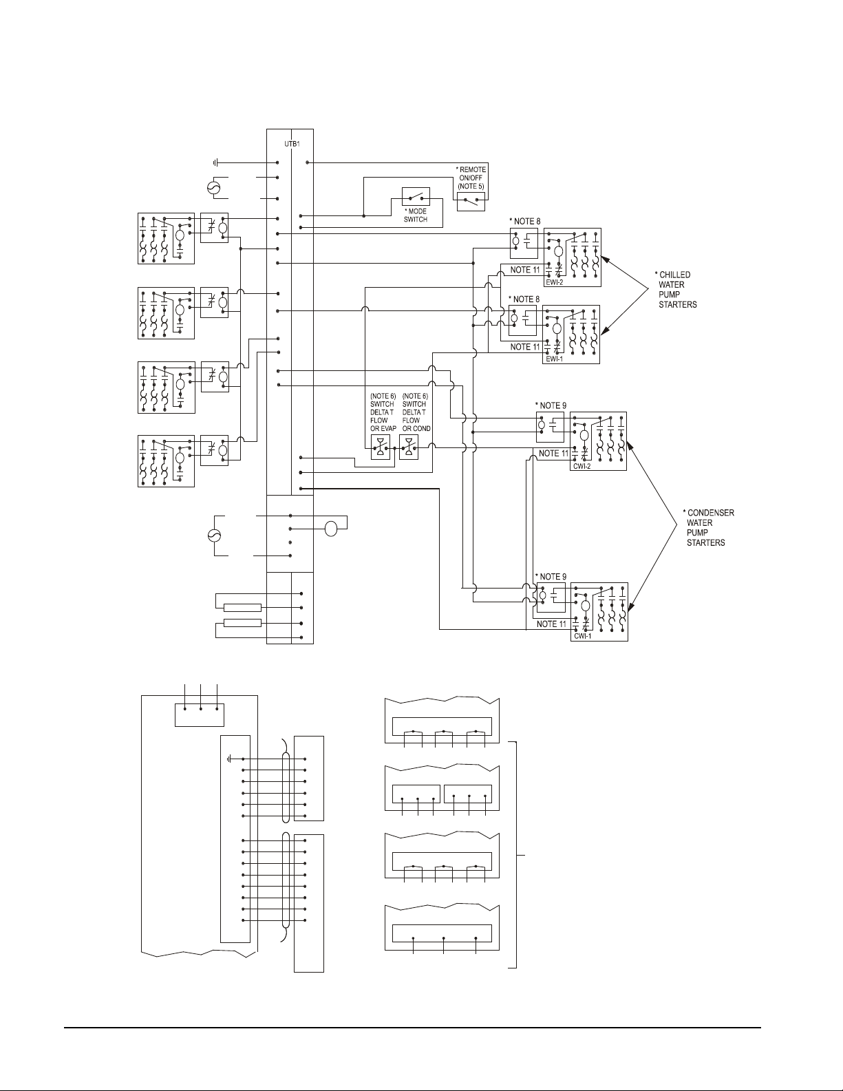
NOTE 12
- FOR DC VOLTAGE AND 4-20 MA
CONNECTIONS (SEE NOTE 3)
- FOR DETAILS OF CONTROL REFER
TO UNIT CONTROL SCHEMATIC
330342103
- COMPRESSOR CONTROL
SCHEMATIC 330342203
- LEGEND: 330343003
* FIELD SUPPLIED ITEM
* NOTE 7
* NOTE 10
* NOTE 10
* NOTE 10
* NOTE 10
330387901-0A
COMMON
NEUTRAL
POWER
Figure 13, Typical Field Connection Diagram, WSC Unit
18 Field Installation Procedure IM 1128-1
Page 19
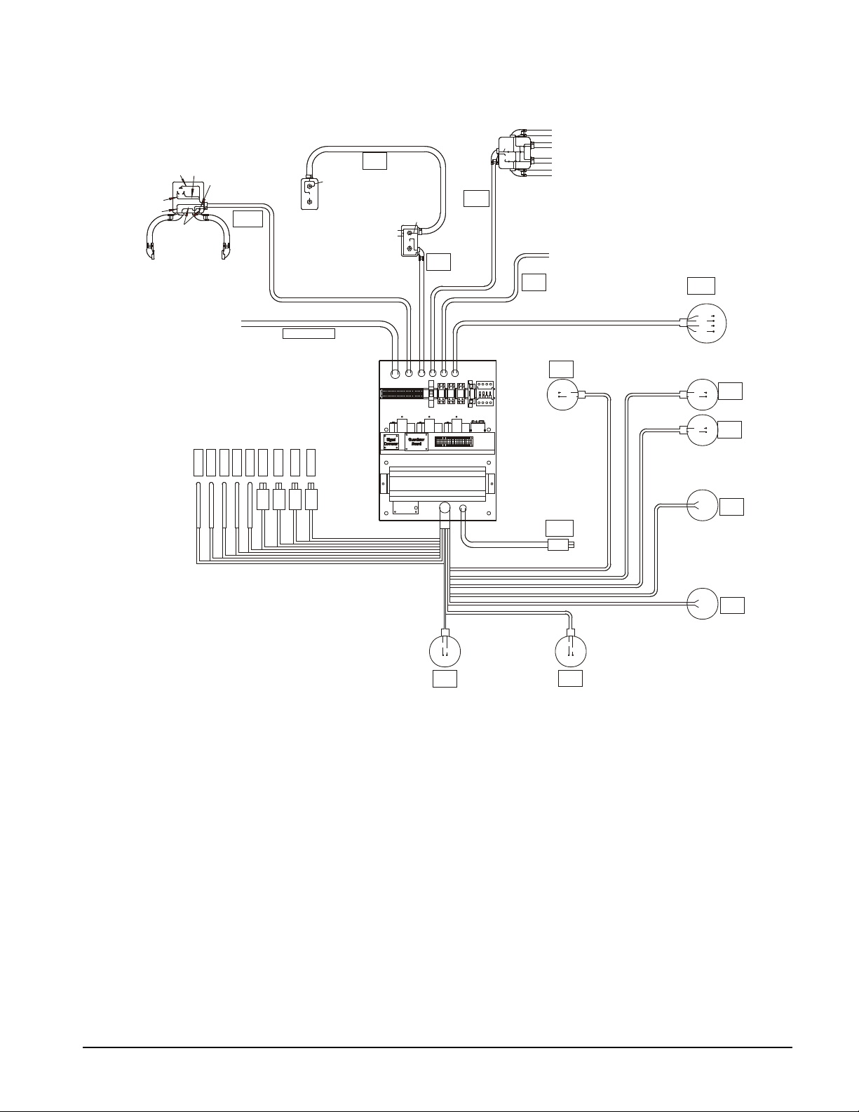
Figure 14, Compressor Control Panel Elect rical and Sensor Connections
R331311501C0100
N7
N7
155
155
155
154
GUARDISTOR
CONNECT LEAD 155
TO TERMINAL IF 2nd
BOX IS NOT USED.
2nd TERMINAL BOX
USED ON SELECTED
MOTORS.
HIGH
PRESSURE
SWITCH
E9
E7
NUMBER OF HEATERS MAY VARY
DUE TO COMPRESSOR SIZE.
JUNCTION BOX NOT ON ALL UNITS.
SECOND HEATER CABLE FROM COMPR.
ON WSC063-087 ONLY.
}
3
2
1
E4
E6
05
0708
E5
OIL PUMP
HEATERS
{TO STARTER
COMPRESSOR
HEATERS
CS04
CS05
CS07
CS09
CS10
CS06
CS03
CS02
CS01
HOT GAS
SOLENOID
LIQ. INJ.
SOLENOID
OPTION
135
136
133
134
141
142
139
140
132
131
137
138
OIL COOLER
SOLENOID
VANE CONTROL
SOLENOIDS
VANE
CLOSE
SWITCH
146
145
VANE
OPEN
SWITCH
103
104
VFD SPEED
SIGNAL
102
101
(ON VFD ONLY)
LI
HG
VO
VC
SA
SB
OC
VFD
LEAVING EVAP WATER TEMP.
OIL FEED TEMP.
COMPR. DISCHARGE TEMP.
COMPR. SUCTION TEMP.
OIL SUMP TEMP.
COND. PRESS. SENSOR
EVAP. PRESS. SENSOR
OIL FEED PRESS. SENSOR
OIL SUMP PRESS. SENSOR
VANE
LOAD
VANE
UNLOAD
JUNCTION BOX ON COMPRESSOR
MOUNTING BRACKET NEAR THE
SUCTION PIPE.
OPH
G2
G1
CP1
CP2
HPS
COMPRESSOR CONTROL BOX
CCB POWER
10 LEADS 4 LEADS
(ON COMPRESSOR)
(ON VFD)
(ON SUPPLY
WATER LINE)
(ON COMPR.
FRONT)
(ON COMPR. NEXT
TO DISCHARGE)
(ON COMPR.
FRONT)
(ON HOT
GAS LINE)
(ON LIQUID
INJ. LINE)
(ON DISCHARGE
NOZZLE)
Note:
Refer to the compressor controller schematic for detailed wiring connections.
IM 1128-1 Field Installation Procedure 19
Page 20
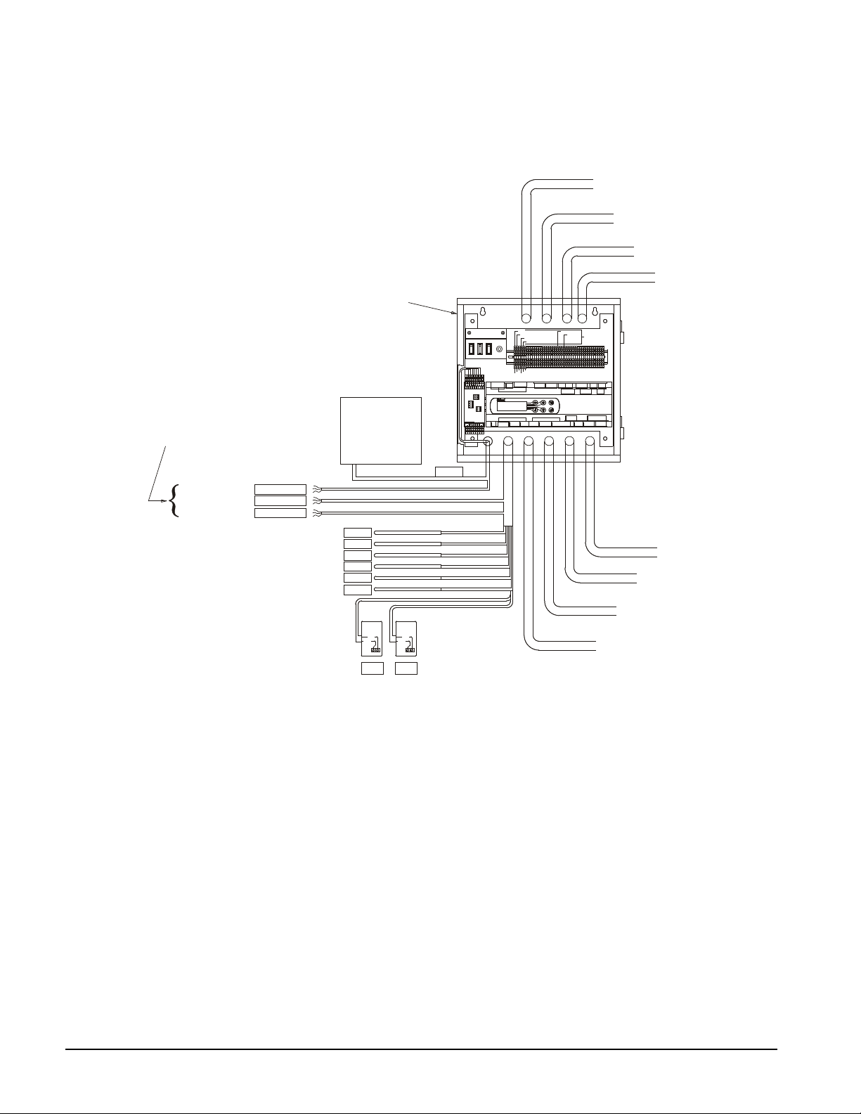
Figure 15, Unit Controller El ect r i cal and Sensor Connections
R331311502C0100
REFERENCE THE UNIT CONTROLLER SCHEMATIC
FOR DETAILED WIRING CONNECTIONS
US03
US04
US05
US09
US10
UNIT CONTROL BOX
US02
515253545556575859606162637070707171717273747576777879808182838485868686PE
PE
R
MICROTECH II
TM
AIR CONDITIONING
J11
J12
J13
J14
J15
J1
J2
B1B2B3
GND
+VDC
J3
B4
BC4B5BC5
J4 J5
J6
J19
J20
Y5Y6B9
BC9
B10
BC10
ID17
ID18
IDC17
J16
J17 J18
J21 J22
J23
SERIAL CARDPRINTER CARD
EXPANSION MEMORY
J7 J8
UNIT COMP 1 COMP 2
CIRCUIT BKR.
ON-(IN)
OFF-(OUT)
PUMP/TOWER
OPERATOR
INTERFACE
PANEL
}
}
}
}
COND. GPM SENSOR
(FIELD OPTION)
EVAP. GPM SENSOR
(FIELD OPTION)
TOWER BYPASS/TOWER VFD
(FIELD OPTION)
WATER RESET/REMOTE START-STOP/
MODE/DEMAND LIMIT
(FIELD OPTION)
}
}
}
}
WATER PUMPS
(FIELD INSTALLED)
TOWER STAGING
(FIELD INSTALLED)
ALARMS
(FIELD INSTALLED)
POWER
(FIELD INSTALLED)
J3
J4
J5
J6
UTB1
CONTROLLER
pCO2
152
C.
N.O.
151
N.O.
C.
149
150
EF
CF
149,151
150
152
249,251
250
252
T3S1
T3S2
EF1
CF1
EF2
CF2
EF BLACK
CF BLACK
EF WHITE
CF WHITE
EF & CF BROWN
EF & CF BLUE
MASS FLOW
SENSOR OPTION
EVAPORATOR
FLOW SWITCH
CONDENSER
FLOW SWITCH
7 LEADS
ENTERING EVAP. WATER TEMP.
ENTERING COND. WATER TEMP.
LEAVING COND. WATER TEMP.
LIQUID LINE TEMP .
ENTERING HEAT RECOVERY
LEAVING HEAT RECOVERY
(OPTIONAL)
(OPTIONAL)
OIP
UC POWER
FS POWER
pLAN
UNIT CONTROLLER
FLOW SWITCH
CONNECT THESE LEADS
TO THE COMPRESSOR
CONTROL BOX
COMMUNICATION
TYPE II KNOCKDOWN ONLY
20 Field Installation Procedure IM 1128-1
Page 21
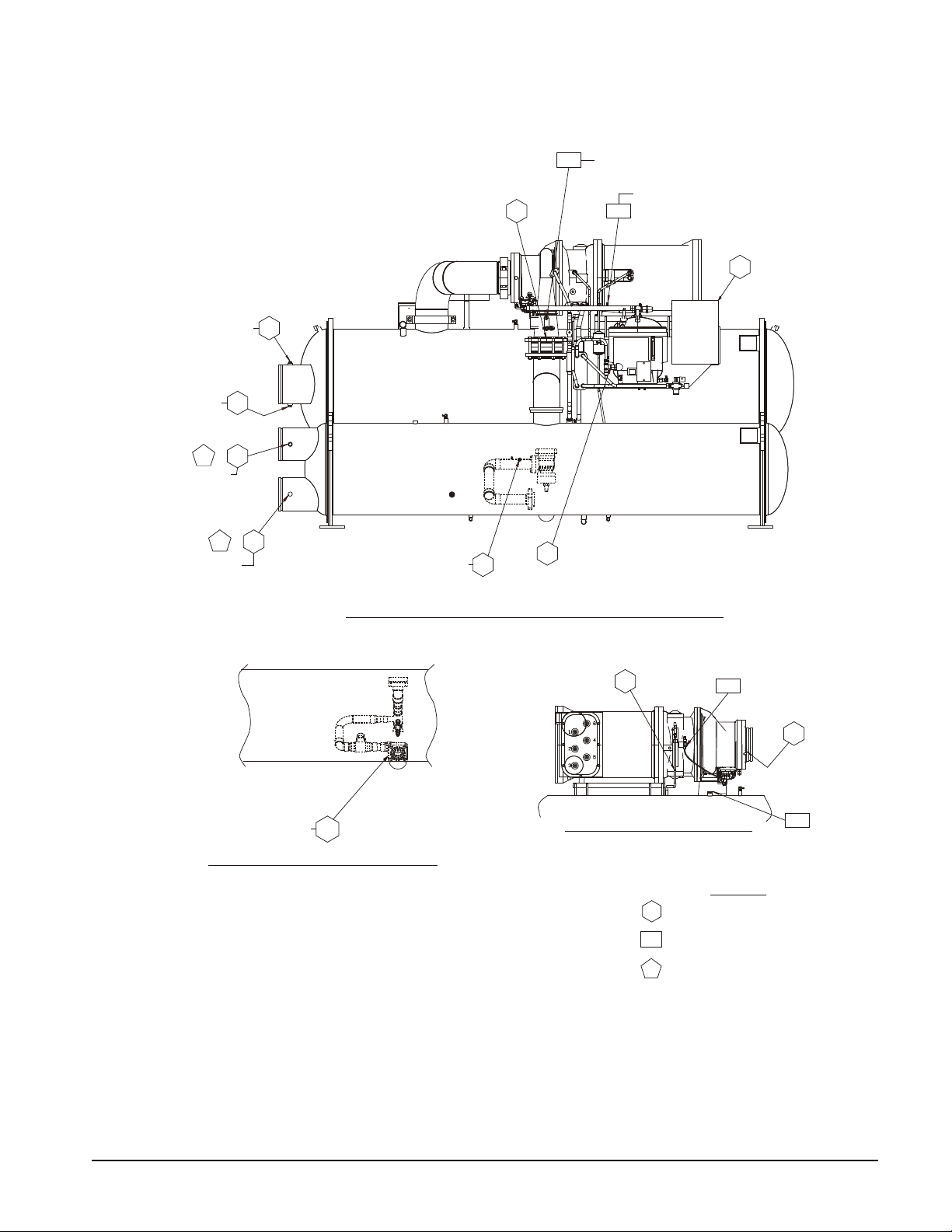
Figure 16, Unit Electrical and Sensor Locat i ons
R3313115
CS10
US04
CS05
US05
CS04
CS09
CS02
CS03
&
&
EVAPORATOR
STANDARD PRESSURE TRANSDUCER
STANDARD TEMPE RATURE SENSOR
OPTIONAL TEMPERATURE SENSOR
SEE DETAIL A
SEE DETAIL C
SEE DETAIL E
SEE DETAIL D
SEE DETAIL D
SEE DETAIL D
SEE DETAIL F
CS01
US02
US10
US09
US03
CS07
CS06
CS08
FRONT VIEW AT COMPRESSOR
FIELD
OPTION
US05
SEE DETAIL E
EVAPORATOR
WITH ELECTRONIC EXPANSION VALVE
REAR VIEW SHOWN WITH PILOT OPERATED EXPANSION VALVE
LEGEND
SEE DETAIL B
SEE
DETAIL D
Note: See Figure 17 for reference detail drawings.
IM 1128-1 Field Installation Procedure 21
Page 22

Figure 17, Unit Sensor Location Detail s
R331311503C0200
DETAIL "C"
TUBE
CS09
DETAIL "D"
US02
DETAIL "E"
US05
US03 US04 CS10
US10US09
CS05
CS05
DETAIL "F”
SUCTION NOZZLE END
OF COMPRESSOR
SENSOR/H.P. SWITCH LOCATION
STANDARD UNIT W/O HOT GAS
CS06
CS06
USE A VAL VE CORE
W/ THIS DEVICE
USE A VAL VE CORE
W/ THIS DEVICE
CS01
VALVE CORE
CONNECTION.
MUST BE IN
DETAIL "A"
ONE
PLACE
ONLY
UNIT WITH HOT GAS
DETAIL 'B'
SENSOR
NUMBER
DESCRIPTION
US03
US04
US05
US02
EVAP. LEAVING W ATER TEMP.
EVAP. ENTERING WATER TEMP.
CS01
CS02
COND. ENTERING WATER TEMP .
US09
COND. LEAVING WATER TEMP.
US10
EVAP. REFRIGERANT PRESSURE
COND. REFRIGERANT PRESSURE
LIQUID LINE TEMPERATURE
CS03
CS06
CS04
COMP. DISCHARGE TEMP.
OIL FEED TEMPERATURE
OIL SUMP TEMPERATURE
OIL SUMP PRESSURE
OIL FEED GAUGE PRESSURE
% COMPRESSOR AMPS (STARTER)
ENT. HEA T RECOVERY TEMP.
LVG. HEAT RECOVER Y T EMP.
SENSOR
NUMBER
DESCRIPTION
CS05
CS07
COMP SUCTION TEMPERATURE
CS08
CS09
CS10
UNIT CONTROL SENSORS
COMPRESSOR CONTROL SENSORS
HIGH PRESSURE SWITCH
DO NOT USE A VALVE
CORE WITH THIS DEVICE
HIGH PRESSURE SWITCH
DO NOT USE A VALVE
CORE WITH THIS DEVICE
DISCHARGE PRESSURE
TRANSDUCER
DISCHARGE PRESSURE
TRANSDUCER
22 Field Installation Procedure IM 1128-1
Page 23

Figure 18, Compressor Control Box
IM 1128-1 Field Installation Procedure 23
Page 24

Figure 19, Unit Control Box
24 Field Installation Procedure IM 1128-1
Page 25

Figure 20, Flow Switch Wiring
IM 1128-1 Field Installation Procedure 25
Page 26

Unit Photographs
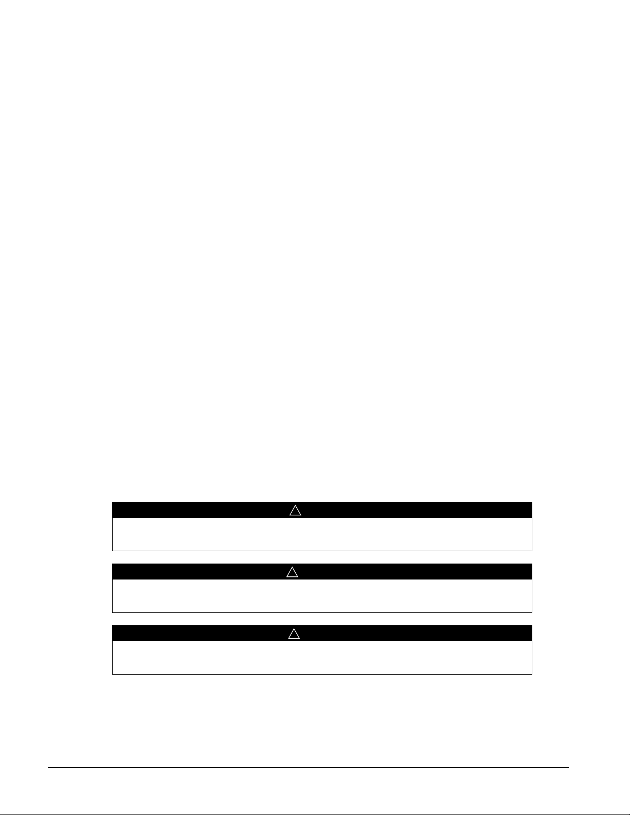
Figure 21, WSC 087, Photo
Figure 22, WSC 100, Photo
26 Field Installation Procedure IM 1128-1
Page 27
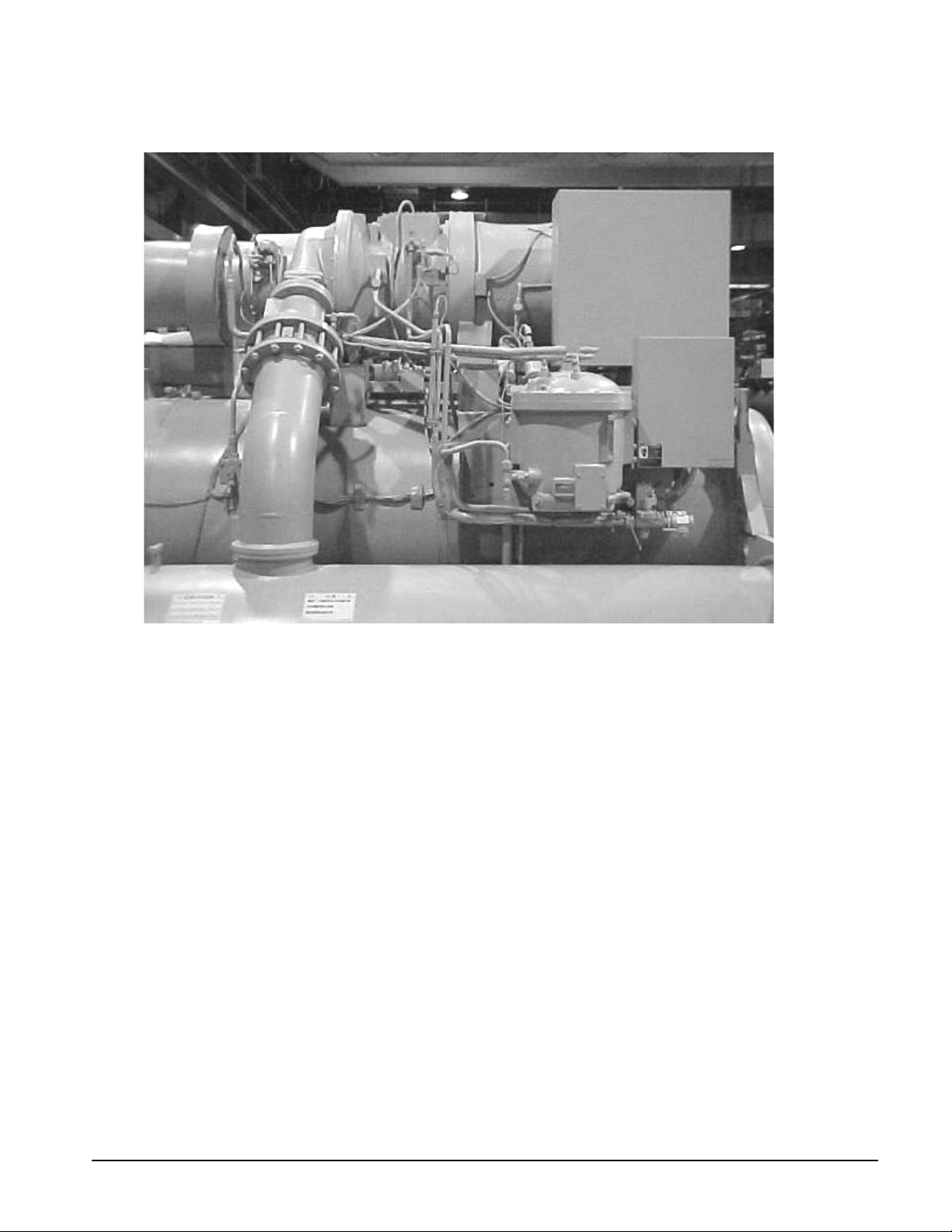
Figure 23, WSC 126, Photo
IM 1128-1 Field Installation Procedure 27
Page 28

Type III Reassembly
Description
TYPE III: The uni t ships fully assembled and is field ready to knockdown. Included are the vessel
bolt-on connection brackets, the discharge stack bolt-on flanges at the condenser and the bolt-on oil
pump assembly.
1. The unit is shipped fully charged with refrigerant and lubricant.
2. The unit will be factory insulated and painted.
3. All electrical and sensor wiring will be fastened as usual.
4. The starter will ship per order instructions.
5. Touch up paint and stick on wire ties will be included.
6. This unit will be fully tested at the factory.
7. Labels will be provided with the instructions to mark piping, electrical wiring and sensor wiring.
Reassembly Steps
Type III units offer a variety of disassembly opportunities. In some cases the condenser and tube
support plate are removed to meet narrow entrance requirements. Sometimes the compressor and unit
control panel are removed for low height situations. Other possibilities exist.
Therefore it is difficult to prescribe step-by-step procedures. Various secti ons of this manual can be
used where applicable, bearing in mind that the unit is fully charged with refrigerant and lubricant.
28 Field Installation Procedure IM 1128-1
Page 29
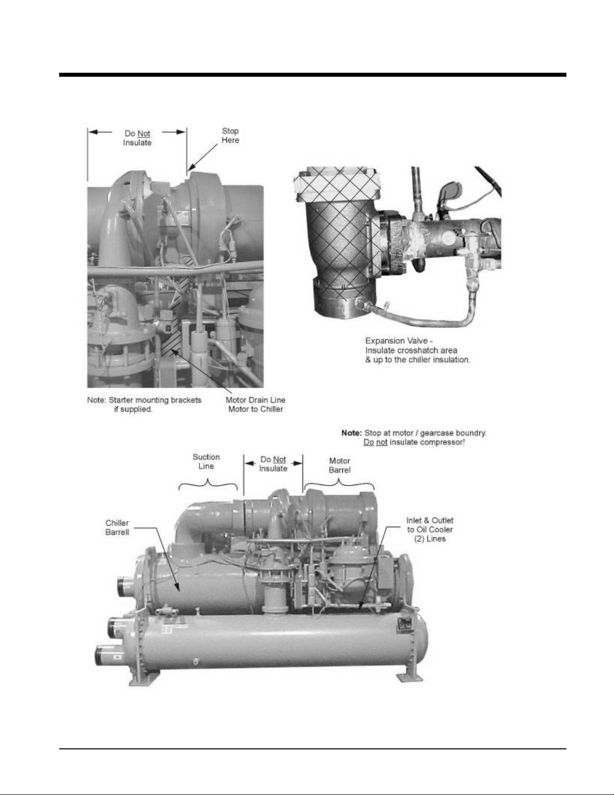
Field Insulation Guide
Figure 24, Insulation Requirem ent s
IM 1128-1 Field Installation Procedure 29
Page 30

30 Field Installation Procedure IM 1128-1
Page 31

Dimensions and Weights
Type I
The following table gives the dimensions and weight of the chiller with the compressor and starter/VFD
removed and the dimensions and weight of the shipped-loose compressor.
Table 1, Type I, Dimensions & Weights
Unit Size Vessel Code
063 E2009 / C1809 57.1 (1450.6) 61.6 (1564.4) 5212 (2366) 44.0 (1118.6) 25.1 (638.3) 2000 (908)
063 E2209 / C2009 57. 1 (1450.6) 64.0 (1624.8) 5919 (2687) 44.0 (1118.6) 25.1 (638.3) 2000 (908)
063 E2209 / C2209 57. 1 (1450.6) 64.0 (1624.8) 6216 (2882) 44.0 (1118.6) 25.1 (638.3) 2000 (908)
063 E2609 / C2209 57. 1 (1450.6) 67.5 (1715.0) 7048 (3200) 44.0 (1118.6) 25.1 (638.3) 2000 (908))
063 E2609 / C2609 57. 1 (1450.6) 73.1 (1857.8) 7784 (3534) 44.0 (1118.6) 25.1 (638.3) 2000 (908)
063 E3009 / C2609 56. 8 (1441.7) 75.7 (1922.0) 9692 (4400) 44.0 (1118.6) 25.1 (638.3) 2000 (908)
063 E2012 / C1812 57. 1 (1450.6) 61.6 (1564.4) 6084 (2762) 44.0 (1118.6) 25.1 (638.3) 2000 (908)
063 E2212 / C2012 57. 1 (1450.6) 64.0 (1624.8) 6982 (3170) 44.0 (1118.6) 25.1 (638.3) 2000 (908))
063 E2212 / C2212 57. 1 (1450. 6) 64. 0 (1624. 8) 7357 (3340) 44.0 (1118.6) 25.1 (638. 3) 2000 (908)
063 E2612 / C2212 57. 1 (1450.6) 67.5 (1715.0) 8377 (3803) 44.0 (1118.6) 25.1 (638.3) 2000 (908)
063 E2612 / C2612 57. 1 (1450.6) 73.1 (1857.8) 9294 (4219) 44.0 (1118.6) 25.1 (638.3) 2000 (908)
063 E3012 / C2612 56. 8 (1441.7) 75.7 (1922.0) 10703 (4859) 44.0 (1118.6) 25.1 (638.3) 2000 (908)
079 E2209 / C2209 50. 2 (1274.6) 62.3 (1581.7) 6940 (3151) 43.6 (1108.2) 25.1 (638.3) 3200 (1452)
079 E2609 / C2209 52. 7 (1338.3) 63.9 (1622.8) 7780 (3532) 43.6 (1108.2) 25.1 (638.3) 3200 (1452)
079 E2609 / C2609 52. 7 (1338.3) 69.5 (1765.6) 8516 (3866) 43.6 (1108.2) 25.1 (638.3) 3200 (1452)
079 E3009 / C2609 57. 1 (1449.8) 74.0 (1878.6) 9692 (4400) 43.6 (1108.2) 25.1 (638.3) 3200 (1452)
079 E3009 / C3009 59. 0 (1499.4) 79.4 (2016.8) 10876 (4938) 43.6 (1108.2) 25.1 (638.3) 3200 (1452)
079 E3609 / C3009 74. 7 (1896.1) 78.8 (2001.0) 12713 (5772) 43.6 (1108.2) 25.1 (638.3) 3200 (1452)
079 E2212 / C2212 50. 2 (1274.6) 62.3 (1581.7) 8081 (3669) 43.6 (1108.2) 25.1 (638.3) 3200 (1452)
079 E2612 / C2212 52. 7 (1338.3) 63.9 (1622.8) 9109 (4135) 43.6 (1108.2) 25.1 (638.3) 3200 (1452)
079 E2612 / C2612 52. 7 (1338.3) 69.5 (1765.6) 10026 (4552 43.6 (1108.2) 25.1 (638. 3) 3200 (1452)
079 E3012 / C2612 57.1 (1449.8) 74.0 (1878.6) 11435 (5191) 43.6 (1108.2) 25.1 (638.3) 3200 (1452)
079 E3012 / C3012 59. 0 (1499.4) 79.4 (2016.8) 12919 (5865) 43.6 (1108.2) 25.1 (638.3) 3200 (1452)
079 E3612 / C3012 74. 7 (1896.1) 78.8 (2001.0) 15140 (6874) 43.6 (1108.2) 25.1 (638.3) 3200 (1452)
Unit Width Unit Height Unit Weight Width Height Weight
Chiller w/o Comp. Compressor
Continued on next page.
IM 1128-1 Field Installation Procedure 31
Page 32

Type 1, Dimensions & Weights, Continued
Unit
Size
087 E2609 / C2209 52.7 (1338.3) 65.2 (1656.3) 7780 (3532) 43.6 (1108.2) 25.1 (638.3) 3200 (1452)
087 E2609 / C2609 52.7 (1338.3) 70.8 (1799.1) 8516 (3866) 43.6 (1108.2) 25.1 (638.3) 3200 (1452)
087 E3009 / C2609 57.1 (1449.8) 68.8 (1746.5) 9692 (4400) 43.6 (1108.2) 25.1 (638.3) 3200 (1452)
087 E3009 I C3009 59.5 (1510.5) 78.7 (1998.0) 10876 (4938) 43.6 (1108.2) 25.1 (638.3) 3200 (1452)
087 E3609 / C3009 74.7 (1896.1) 78.8 (2001.0) 12713 (5772) 43.6 (1108.2) 25.1 (638.3) 3200 (1452)
087 E2612 / C2212 52.7 (1338.3) 65.2 (1656.3) 9109 (4135) 43.6 (1108.2) 25.1 (638.3) 3200 (1452)
087 E2612 / C2612 52.7 (1338.3) 70.8 (1799.1) 10029 (4553) 43.6 (1108.2) 25.1 (638.3) 3200 (1452)
087 E3012 / C2612 57.1 (1449.8) 68.8 (1746.5) 11435 (5191) 43.6 (1108.2) 25.1 (638.3) 3200 (1452)
087 E3012 / C3012 59.5 (1510.5) 78.7 (1998.0) 12918 (5865) 43.6 (1108.2) 25.1 (638.3) 3200 (1452)
087 E3612 / C3012 74.7 (1896.1) 78.8 (2001.0) 15139 (6873) 43.6 (1108.2) 25.1 (638.3) 3200 (1452)
087 E3612 / C3612 80.7 (2049.3) 89.2 (2264.4) 17384 (7892) 43.6 (1108.2) 25.1 (638.3) 3200 (1452)
100 E3012 / C3012 67.4 (1712.2) 76.5 (1943.1) 13397 (6082) 44.0 (1117.9) 31.5 (800.1) 6000 (2724)
100 E3612 / C3012 77.2 (1961.6) 77.6 (1971.5) 15587 (7076) 44.0 (1117.9) 31.5 (800.1) 6000 (2724)
100 E3612 / C3612 83.2 (2114.0) 77.6 (1971.5) 17826 (8093) 44.0 (1117.9) 31.5 (800.1) 6000 (2724)
100 E4212 / C3612 86.2 (2190.5) 76.4 (1940.8) 20487 (9301) 44.0 (1117.9) 31.5 (800.1) 6000 (2724)
100 E4212 / C4212 92.2 (2342.9) 86.7 (2202.7) 23298 (10577) 44.0 (1117.9) 31.5 (800.1) 6000 (2724)
100 E4812 / C4212 98. 2 (2495.3) 90.6 (2300.2) 26024 (11815) 44.0 (1117.9) 31.5 (800.1) 6000 (2724)
113 E3012 / C3012 67.4 (1712.2) 76.5 (1943.1) 13397 (6082) 44.0 (1117.9) 31.5 (800.1) 6000 (2724)
113 E3612 / C3012 77.2 (1961.6) 77.6 (1971.5) 15578 (7072) 44.0 (1117.9) 31.5 (800.1) 6000 (2724)
113 E3612 / C3612 83.2 (2114.0) 77.6 (1971.5) 17826 (8093) 44.0 (1117.9) 31.5 (800.1) 6000 (2724)
113 E4212 / C3612 86.2 (2190.5) 76.4 (1940.8) 20457 (9287) 44.0 (1117.9) 31.5 (800.1) 6000 (2724)
113 E4212 / C4212 92.2 (2342.9) 86.7 (2202.7) 23298 (10577) 44.0 (1117.9) 31.5 (800.1) 6000 (2724)
113 E4812 / C4212 98.2 (2495.3) 90.6 (2300.2) 26024 (11815) 44.0 (1117.9) 31.5 (800.1) 6000 (2724)
113 E4812 / C4812 104.2 (2647.7) 90.6 (2300.2) 29016 (13173) 44.0 (1117.9) 31.5 (800.1) 6000 (2724)
126 E3612 / C3012 77.2 (1961.6) 77.6 (1971.5) 15680 (7119) 44.0 (1117.9) 31.5 (800.1) 6000 (2724)
126 E3612 / C3612 83.2 (2114.0) 77.6 (1971.5) 17826 (8093) 44.0 (1117.9) 31.5 (800.1) 6000 (2724)
126 E4212 / C3612 86.2 (2190.5) 76.4 (1940.8) 20457 (9287) 44.0 (1117.9) 31.5 (800.1) 6000 (2724)
126 E4212 / C4212 92.2 (2342.9) 86.7 (2202.7) 23298 (10577) 44.0 (1117.9) 31.5 (800.1) 6000 (2724)
126 E4812 / C4212 98.2 (2495.3) 90.6 (2300.2) 26024 (11815) 44.0 (1117.9) 31.5 (800.1) 6000 (2724)
126 E4812 / C4812 104.2 (2647.7) 90.6 (2300.2) 29016 (13173) 44.0 (1117.9) 31.5 (800.1) 6000 (2724)
Notes:
1. The overall vessel length can vary depending on the s pec i fied tube length and pass arrangement. Consult the Daikin McQuay
2. Allow plus / minus 1 inc h (24.5mm) for factory manufacturing tolerance.
3. All dimensions are s hown in inc hes (mm). All weights are shown in lbs (kg).
Vessel Code
certified submittal drawings, or unit dimensions in Catalog WSCWDC-4 for specific ves sel lengths.
Unit Width Unit Height Unit Weight Width Height Weight
Chiller w/o Comp. Compressor
32 Field Installation Procedure IM 1128-1
Page 33

Type II
Width
Height
The following tables give the dimensions and weights of the various components as shipped.
Table,2 Type II Dimensions & Weights
Unit
Size
063 E2009 / C1809
063 E2209 / C2009
063 E2209 / C2209
063 E2609 / C2209
063 E2609 / C2609
063 E3009 / C2609
063 E2012 / C1812
063 E2212 / C2012
063 E2212 / C2212
063 E2612 / C2212
063 E2612 / C2612
063 E3012 / C2612
079 E2209 / C2209
079 E2609 / C2209
079 E2609 / C2609
079 E3009 / C2609
079 E3009 / C3009
079 E3609 / C3009
079 E2212 / C2212
079 E2612 / C2212
079 E2612 / C2612
079 E3012 / C2612
079 E3012 / C3012
079 E3612 / C3012
Vessel Code
Cond.
Width
31.8
(806.5)
30.5
(774.2)
30.5
(774.2)
30.5
(774.2)
36.0
(914.9)
36.0
(914.9)
31.8
(806.5)
30.5
(774.2)
30.5
(774.2)
30.5
(774.2)
36.0
(914.9)
36.0
(914.9)
30.5
(775.2)
30.5
(775.2)
30.5
(775.2)
36.0
(914.9)
41.4
(1052.3)
41.9
(1063.5)
30.5
(775.2)
30.5
(775.2)
30.5
(775.2)
36.0
(914.9)
41.4
(1052.3)
41.9
(1063.5)
Table continued on next p age.
Cond.
Height
36.8
(933.5)
36.8
(933.5)
36.8
(933.5)
36.8
(933.5)
42.3
(1073.2)
42.3
(1073.2)
36.8
(933.5)
36.8
(933.5)
36.8
(933.5)
36.8
(933.5)
42.3
(1073.2)
42.3
(1073.2)
33.1
(841.0)
35.9
(911.4)
39.3
(997.0)
39.3
(997.0)
45.8
(1162.1)
45.8
(1162.1)
33.1
(841.0)
35.9
(911.4)
39.3
(997.0)
39.3
(997.0)
45.8
(1162.1)
45.8
(1162.1)
Front &
Back
Support
8.0 (203.2)
8.0 (203.2)
8.0 (203.2)
8.0 (203.2)
8.0 (203.2)
8.0 (203.2)
8.0 (203.2)
8.0 (203.2)
8.0 (203.2)
8.0 (203.2)
8.0 (203.2)
8.0 (203.2)
8.0 (203.2)
8.0 (203.2)
8.0 (203.2)
8.0 (203.2)
8.0 (203.2)
8.0 (203.2)
8.0 (203.2)
8.0 (203.2)
8.0 (203.2)
8.0 (203.2)
8.0 (203.2)
8.0 (203.2)
Front &
Back
Support
22.9
(580.9)
22.9
(580.9)
22.1
(561.8)
22.1
(561.8)
27.7
(704.6)
27.0
(685.5)
22.9
(580.9)
22.9
(580.9)
22.1
(561.8)
22.1
(561.8)
27.7
(704.6)
27.0
(685.5)
20.6
(522.0)
20.6
(522.0)
26.2
(665.0)
25.4
(645.2)
30.9
(783.8)
25.5
(648.7)
20.6
(522.0)
20.6
(522.0)
26.2
(665.0)
25.4
(645.2)
30.9
(783.8)
25.5
(648.7)
Evaporator
Width
34.6
(877.8)
34.6
(877.8)
34.6
(877.8)
39.2
(996.7)
39.2
(996.7)
42.6
(1081.0)
34.6
(877.8)
34.6
(877.8)
34.6
(877.8)
39.2
(996.7)
39.2
(996.7)
42.6
(1081.0)
32.8
(834.1)
36.7
(933.2)
36.7
(933.2)
40.1
(1017.8)
42.6
(1081.0)
48.1
(1222.2)
32.8
(834.1)
36.7
(933.2)
36.7
(933.2)
40.1
(1017.8)
42.6
(1081.0)
48.1
(1222.2)
Evaporator
Height
28.8
(731.3)
35.4
(899.9)
35.4
(899.9)
35.9
(912.6)
35.9
(912.6)
37.3
(948.4)
28.8
(731.3)
35.4
(899.9)
35.4
(899.9)
35.9
(912.6)
35.9
(912.6)
37.3
(948.4)
31.5
(799.8)
33.2
(842.3)
33.2
(842.3)
37.3
(948.4)
37.3
(948.4)
43.7
(1109.7)
31.5
(799.8)
33.2
(842.3)
33.2
(842.3)
37.3
(948.4)
37.3
(948.4)
43.7
(1109.7)
Compressor
Width
44.0
(1118.6)
44.0
(1118.6)
44.0
(1118.6)
44.0
(1118.6)
44.0
(1118.6)
44.0
(1118.6)
44.0
(1118.6)
44.0
(1118.6)
44.0
(1118.6)
44.0
(1118.6)
44.0
(1118.6)
44.0
(1118.6)
43.6
(1108.2)
43.6
(1108.2)
43.6
(1108.2)
43.6
(1108.2)
43.6
(1108.2)
43.6
(1108.2)
43.6
(1108.2)
43.6
(1108.2)
43.6
(1108.2)
43.6
(1108.2)
43.6
(1108.2)
43.6
(1108.2)
Compressor
Height
25.1
(638.3)
25.1
(638.3)
25.1
(638.3)
25.1
(638.3)
25.1
(638.3)
25.1
(638.3)
25.1
(638.3)
25.1
(638.3)
25.1
(638.3)
25.1
(638.3)
25.1
(638.3)
25.1
(638.3)
25.1
(638.3)
25.1
(638.3)
25.1
(638.3)
25.1
(638.3)
25.1
(638.3)
25.1
(638.3)
25.1
(638.3)
25.1
(638.3)
25.1
(638.3)
25.1
(638.3)
25.1
(638.3)
25.1
(638.3)
IM 1128-1 Field Installation Procedure 33
Page 34

Type II Dimensions & Weights, Continued
Width
Height
Unit
Size
Vessel Code
Cond.
Width
Cond.
Height
Front &
Back
Support
Front &
Back
Support
Evaporator
Width
Evaporator
Height
Compressor
Width
Compressor
Height
087 E2609 / C2209 30.5 (775.2) 36.8 (933.5) 8.0 (203.2) 20.6 (522.0)
087 E2609 / C2609 36.0 (914.9) 41.8 (1060.5) 8.0 (203.2) 26.2 (665.0)
087 E3009 / C2609 36.0 (914.9) 41.8 (1060.5) 8.0 (203.2) 25.4 (645.2)
087 E3009 / C3009 41.9 (1063.5) 45.8 (1162.1) 8.0 (203.2) 30.9 (783.8)
087 E3609 / C3009 41.9 (1063.5) 45.8 (1162.1) 8.0 (203.2) 25.5 (648.7)
087 E2612 / C2612 36.0 (914.9) 41.8 (1060.5) 8.0 (203.2) 26.2 (665.0)
087 E3012 / C2612 36.0 (914.9) 41.8 (1060.5) 8.0 (203.2) 25.4 (645.2)
087 E3012 / C3012 41.9 (1063.5) 45.8 (1162.1) 8.0 (203.2) 30.9 (783.8)
087 E3612 / C3012 41.9 (1063.5) 45.8 (1162.1) 8.0 (203.2) 25.5 (648.7)
087 E3612 / C3612 46.2 (1173.2) 51.8 (1314.5) 8.0 (203.2) 35.9 (912.1)
100 E3012 / C3012 41.0 (1041.9) 46.2 (1172.7) 8.0 (203.2) 28.6 (725.4)
100 E3612 / C3012 41.0 (1041.9) 46.2 (1172.7) 8.0 (203.2) 24.4 (619.5)
100 E3612 / C3612 45.3 (1151.4) 52.1 (1322.3) 8.0 (203.2) 24.4 (619.5)
100 E4212 / C3612 45.3 (1151.4) 52.1 (1322.3) 8.0 (203.2) 18.6 (473.5)
100 E4212 / C4212 49.6 (1260.1) 57.6 (1462.0) 8.0 (203.2) 21.4 (543.3)
100 E4812 / C4212 49.6 (1260.1) 57.6 (1462.0) 8.0 (203.2) 19.6 (498.9)
113 E3012 / C3012 41.0 (1041.9) 46.2 (1172.7) 8.0 (203.2) 28.6 (725.4)
113 E3612 / C3012 41.0 (1041.9) 46.2 (1172.7) 8.0 (203.2) 24.4 (619.5)
113 E3612 / C3612 45.3 (1151.4) 52.1 (1322.3) 8.0 (203.2) 24.4 (619.5)
113 E4212 / C3612 45.3 (1151.4) 52.1 (1322.3) 8.0 (203.2) 18.6 (473.5)
113 E4212 / C4212 49.6 (1260.1) 57.6 (1462.0) 8.0 (203.2) 21.4 (543.3)
113 E4812 / C4212 49.6 (1260.1) 57.6 (1462.0) 8.0 (203.2) 19.6 (498.9)
113 E4812 / C4812 53.9 (1369.1) 63.5 (1612.9) 8.0 (203.2) 19.6 (498.9)
Table continued on next p age.
39.2
(996.7)
39.2
(996.7)
42.6
(1081.3)
42.6
(1081.3)
48.1
(1222.2)
39.2
(996.7)
42.6
(1081.3)
42.6
(1081.3)
48.1
(1222.2)
48.1
(1222.2)
48.4
(1229.6)
52.1
(1324.1)
52.1
(1324.1)
54.4
(1382.5)
54.4
(1382.5)
60.1
(1527.0)
48.4
(1229.6)
52.1
(1324.1)
52.1
(1324.1)
54.4
(1382.5)
54.4
(1382.5)
60.1
(1527.0)
60.1
(1527.0)
35.9
(912.6)
35.9
(912.6)
37.3
(948.4)
37.3
(948.4)
43.7
(1109.7)
35.9
(912.6)
37.3
(948.4)
37.3
(948.4)
43.7
(1109.7)
43.7
(1109.7)
38.4
(974.6)
44.1
(1120.6)
44.1
(1120.6)
51.5
(1307.6)
51.5
(1307.6)
57.1
(1449.6)
38.4
(974.6)
44.1
(1120.6)
44.1
(1120.6)
51.5
(1307.6)
51.5
(1307.6)
57.1
(1449.6)
57.1
(1449.6)
43.6
(1108.2)
43.6
(1108.2)
43.6
(1108.2)
43.6
(1108.2)
43.6
(1108.2)
43.6
(1108.2)
43.6
(1108.2)
43.6
(1108.2)
43.6
(1108.2)
43.6
(1108.2)
44.0
(1117.9)
44.0
(1117.9)
44.0
(1117.9)
44.0
(1117.9)
44.0
(1117.9)
44.0
(1117.9)
44.0
(1117.9)
44.0
(1117.9)
44.0
(1117.9)
44.0
(1117.9)
44.0
(1117.9)
44.0
(1117.9)
44.0
(1117.9)
25.1
(638.3)
25.1
(638.3)
25.1
(638.3)
25.1
(638.3)
25.1
(638.3)
25.1
(638.3)
25.1
(638.3)
25.1
(638.3)
25.1
(638.3)
25.1
(638.3)
31.5
(800.1)
31.5
(800.1)
31.5
(800.1)
31.5
(800.1)
31.5
(800.1)
31.5
(800.1)
31.5
(800.1)
31.5
(800.1)
31.5
(800.1)
31.5
(800.1)
31.5
(800.1)
31.5
(800.1)
31.5
(800.1)
34 Field Installation Procedure IM 1128-1
Page 35

Type II Dimensions & Weights, Continued
Width
Height
Front &
Unit
Size
Vessel Code
Cond.
Width
Cond.
Height
Back
Support
Front &
Back
Support
Evaporator
Width
Evaporator
Height
Compressor
Width
Compressor
Height
126 E3612 / C3012 41.0 (1041.9) 46.2 (1172.7) 8.0 (203.2) 24.4 (619.5)
126 E3612 / C3612 45.3 (1151.4) 52.1 (1322.3) 8.0 (203.2) 24.4 (619.5)
126 E4212 / C3612 45.3 (1151.4) 52.1 (1322.3) 8.0 (203.2) 18.6 (473.5)
126 E4212 / C4212 49.6 (1260.1) 57.6 (1462.0) 8.0 (203.2) 21.4 (543.3)
126 E4812 / C4212 49.6 (1260.1) 57.6 (1462.0) 8.0 (203.2) 19.6 (498.9)
126 E4812 / C4812 53.9 (1369.1) 63.5 (1612.9) 8.0 (203.2) 19.6 (498.9)
Notes:
1. The overall vessel length can vary depending on t he specified tube length and pass arrangement. Consult the Daikin McQuay
certified submittal drawings, or unit dimensions in Catalog WSCWDC-4 for specific ves sel lengths.
2. Allow plus / minus 1 i nch (24.5mm) for fact ory manufacturing tolerance.
3. All dimensions are shown in inches (mm). A l l weights are shown in lbs (kg).
52.1
(1324.1)
52.1
(1324.1)
54.4
(1382.5)
54.4
(1382.5)
60.1
(1527.0)
60.1
(1527.0)
44.1
(1120.6)
44.1
(1120.6)
51.5
(1307.6)
51.5
(1307.6)
57.1
(1449.6)
57.1
(1449.6)
44.0
(1117.9)
44.0
(1117.9)
44.0
(1117.9)
44.0
(1117.9)
44.0
(1117.9)
44.0
(1117.9)
31.5
(800.1)
31.5
(800.1)
31.5
(800.1)
31.5
(800.1)
31.5
(800.1)
31.5
(800.1)
IM 1128-1 Field Installation Procedure 35
Page 36

Type II Dimensions & Weights, Continued
063
E2212 / C2012
20.8 (528.1)
30.6 (778.0)
2677 (1213)
3071 (1391)
3200 (1440)
11382 (5163)
079
E3012 / C3012
18.8 (476.5)
29.1 (739.6)
5333 (2416)
5075 (2299)
3200 (1440)
17319 (7856)
087
E2609 / C2209
19.8 (501.9)
26.7 (678.9)
2511 (1137)
3381 (1532)
3200 (1440)
12180 (5525)
087
E2609 / C2609
19.8 (501.9)
26.7 (678.9)
3210 (1454)
3381 (1532)
3200 (1440)
12916 (5859)
Unit
Size
063 E2009 / C1809 20.8 (528.1) 30.6 (778.0) 1835 (831) 2543 (1152) 3200 (1440) 9612 (4360)
063 E2209 / C2009 20.8 (528.1) 30.6 (778.0) 2230 (1010) 2708 (1227) 3200 (1440) 10319 (4681)
063 E2209 / C2209 20.8 (528.1) 30.6 (778.0) 2511 (1137) 2708 (1227) 3200 (1440) 10616 (4815)
063 E2609 / C2209 20.8 (528.1) 30.6 (778.0) 2511 (1137) 3381 (1532) 3200 (1440) 11448 (5193)
063 E2609 / C2609 20.8 (528.1) 30.6 (778.0) 3210 (1454) 3381 (1532) 3200 (1440) 12184 (5527)
063 E3009 / C2609 20.8 (528.1) 30.6 (778.0) 3210 (1454) 4397 (1992) 3200 (1440) 14092 (6392)
063 E2012 / C1812 20.8 (528.1) 30.6 (778.0) 2183 (989) 2862 (1296) 3200 (1440) 10484 (4756)
063 E2212 / C2212 20.8 (528.1) 30.6 (778.0) 3031 (1373) 3071 (1391) 3200 (1440) 11757 (5333)
063 E2612 / C2212 20.8 (528.1) 30.6 (778.0) 3031 (1373) 3880 (1758) 3200 (1440) 12777 (5796)
063 E2612 / C2612 20.8 (528.1) 30.6 (778.0) 3900 (1767) 3880 (1758) 3200 (1440) 13694 (6203)
063 E3012 / C2612 20.8 (528.1) 30.6 (778.0) 3900 (1767) 5075 (2299) 3200 (1440) 15103 (6851)
079 E2209 / C2209 18.8 (476.5) 29.1 (739.6) 2511 (1137) 2708 (1227) 3200 (1440) 11340 (5144)
079 E2609 / C2209 18.8 (476.5) 29.1 (739.6) 2511 (1137) 3381 (1532) 3200 (1440) 12180 (5525)
079 E2609 / C2609 18.8 (476.5) 29.1 (739.6) 3210 (1454) 3381 (1532) 3200 (1440) 12916 (5859)
079 E3009 / C2609 18.8 (476.5) 29.1 (739.6) 3210 (1454) 4397 (1992) 3200 (1440) 14092 (6392)
079 E3009 / C3009 18.8 (476.5) 29.1 (739.6) 4356 (1973) 4397 (1992) 3200 (1440) 15276 (6929)
079 E3609 / C3009 19.8 (501.9) 26.7 (678.9) 4356 (1973) 5882 (2665) 3200 (1440) 17113 (7762)
079 E2212 / C2212 18.8 (476.5) 29.1 (739.6) 3031 (1373) 3071 (1391) 3200 (1440) 12481 (5661)
079 E2612 / C2212 18.8 (476.5) 29.1 (739.6) 3031 (1373) 3880 (1758) 3200 (1440) 13509 (6128)
079 E2612 / C2612 18.8 (476.5) 29.1 (739.6) 3900 (1767) 3880 (1758) 3200 (1440) 14426 (6544)
079 E3012 / C2612 18.8 (476.5) 29.1 (739.6) 3900 (1767) 5075 (2299) 3200 (1440) 15835 (7183)
Vessel Code
Oil Pump
Width
Oil Pump
Height
Condenser
Weight
Evaporator
Weight
Compressor
Weight
Unit Shipping
Weight
079 E3612 / C3012 19.8 (501.9) 26.7 (678.9) 5333 (2416) 6840 (3099) 3200 (1440) 19539 (8863)
087 E3009 / C2609 19.8 (501.9) 26.7 (678.9) 3210 (1454) 4397 (1992) 3200 (1440) 14092 (6392)
087 E3009 / C3009 19.8 (501.9) 26.7 (678. 9) 4356 (1973) 4397 (1992) 3200 (1440) 15276 (6929)
087 E3609 / C3009 19.8 (501.9) 26.7 (678.9) 4356 (1973) 5882 (2665) 3200 (1440) 17113 (7762)
087 E2612 / C2212 19.8 (501.9) 26.7 (678.9) 3031 (1373) 3880 (1758) 3200 (1440) 13509 (6128)
087 E2612 / C2612 19.8 (501.9) 26.7 (678.9) 3900 (1767) 3880 (1758) 3200 (1440) 14426 (6544)
087 E3012 / C2612 19.8 (501.9) 26.7 (678.9) 3900 (1767) 5075 (2299) 3200 (1440) 15835 (7183)
087 E3012 / C3012 19.8 (501.9) 26.7 (678.9) 5333 (2416) 5075 (2299) 3200 (1440) 17318 (7855)
087 E3612 / C3012 19.8 (501.9) 26.7 (678.9) 5333 (2416) 6840 (3099) 3200 (1440) 19539 (8863)
087 E3612 / C3612 19.8 (501.9) 26.7 (678.9) 7508 (3401) 6840 (3099) 3200 (1440) 21784 (9881)
Table continued on next page.
36 Field Installation Procedure IM 1128-1
Page 37

Type II Dimensions & Weights, Continued
100
E4212 / C4212
19.8 (501.9)
34.8 (884.4)
10267 (4651)
8922 (4042)
6000 (2700)
30498 (13834)
Unit
Size
100 E3012 / C3012 19.8 (501.9) 34.8 (884.4) 5333 (2416) 5075 (2299) 6000 (2700) 20597 (9343)
100 E3612 / C3012 19.8 (501.9) 34.8 (884.4) 5333 (2416) 6840 (3099) 6000 (2700) 22778 (10332)
100 E3612 / C3612 19.8 (501.9) 34.8 (884.4) 7508 (3401) 6840 (3099) 6000 (2700) 25026 (11352)
100 E4212 / C3612 19.8 (501.9) 34.8 (884.4) 7508 (3401) 8922 (4042) 6000 (2700) 27657 (13545)
100 E4812 / C4212 19.8 (501.9) 34.8 (884.4) 10267 (4651) 11125 (5040) 6000 (2700) 33224 (15070)
113 E3012 / C3012 19.8 (501.9) 34.8 (884.4) 5333 (2416) 5075 (2299) 6000 (2700) 20597 (9343)
113 E3612 / C3012 19.8 (501.9) 34.8 (884.4) 5333 (2416) 6840 (3099) 6000 (2700) 22778 (10332)
113 E3612 / C3612 19.8 (501.9) 34.8 (884.4) 7508 (3401) 6840 (3099) 6000 (2700) 25026 (11352)
113 E4212 / C3612 19.8 (501.9) 34.8 (884.4) 7508 (3401) 8922 (4042) 6000 (2700) 27657 (13545)
113 E4212 / C4212 19.8 (501.9) 34.8 (884.4) 10267 (4651) 8922 (4042) 6000 (2700) 30498 (13834)
113 E4812 / C4212 19.8 (501.9) 34.8 (884.4) 10267 (4651) 11125 (5040) 6000 (2700) 33224 (15070)
113 E4812 / C4812 19.8 (501.9) 34.8 (884.4) 13077 (5924) 11125 (5040) 6000 (2700) 36216 (16427)
126 E3612 / C3012 19.8 (501.9) 34.8 (884.4) 5333 (2416) 6840 (3099) 6000 (2700) 22880 (10378)
126 E3612 / C3612 19.8 (501.9) 34.8 (884.4) 7508 (3401) 6840 (3099) 6000 (2700) 25128 (11398)
126 E4212 / C3612 19.8 (501.9) 34.8 (884.4) 7508 (3401) 8922 (4042) 6000 (2700) 27657 (12545)
126 E4212 / C4212 19.8 (501.9) 34.8 (884.4) 10267 (4651) 8922 (4042) 6000 (2700) 30498 (13834)
126 E4812 / C4212 19.8 (501.9) 34.8 (884.4) 10267 (4651) 11125 (5040) 6000 (2700) 33224 (15070)
126 E4812 / C4812 19.8 (501.9) 34.8 (884.4) 13077 (5924) 11125 (5040) 6000 (2700) 36216 (16427)
Vessel Code
Notes:
1. The overall vessel length can vary depending on the specified tube length and pass arrangement. Consult the Daikin McQuay
certified submittal drawings, or unit dimensions in Catalog WSCWDC-4 for specific ves sel lengths.
2. The oil pump width is the dimension from front to back. The height is from the bottom of the sump to the top of the piping
connections. Transporti ng the oil pump is usually not an i s sue when compared to the vessels.
3. Allow plus / minus 1 inc h (24.5mm) for manufacturing tolerance.
4. All dimensions are s hown in inc hes (mm).
5. All weights are shown in lbs. (kg).
Oil Pump
Width
Oil Pump
Height
Condenser
Weight
Evaporator
Weight
Compressor
Weight
Unit Shipping
Weight
IM 1128-1 Field Installation Procedure 37
Page 38

Shipping Lists
LEAVE OR
LIQUID
INJECTION
BLOCK-OFF
AND SECURE
MOTOR
COOLING
BLOCK-OFF
AND SECURE
MOTOR
DRAIN
COMP. TO LARGE MOTOR
DRAIN
BLOCK-OFF
AND SECURE
REMOVE AND
CRATE
CRATE
REMOVE PART
REMOVE PART
REMOVE AND
CRATE
DWG.
TOUCH UP SPRAY PAINT
CANS
Daikin McQuay LONMARK
LABEL BAG
IN MANILLA ENVELOPE
IF UNIT
MOUNTED
PANEL
IF UNIT
MOUNTED
CONTROL BOX WATE R
HOSES
ASSY
Table 3, Type I WSC Knockdown Shipping List
LOOSE
LABEL DESCRIPTION
PARTS
FROM - TO REF. DWG.
QTY.
COPPER PIPE ASSY’S
HOT GAS
MOTOR
DRAIN
OIL DRAIN OIL PUMP DRAIN 1 COMP. TO OIL PUMP R331311302
OIL VENT OIL PUMP VENT 1 COMP. TO OIL PUMP R331311302
OIL RETURN OIL RETURN TUBE (THRUS T ) 1
OIL SUPPLY OIL SUPPLY TUBE 1 COMP. TO OIL COOLER BTM. R331311302
HOT GAS BYPASS
(OPTION)
LIQUID INJECTI ON N/A COND. BO T T O M TO CO MP R. R331311303
MOTOR COOLING N/A COND. TO MOTOR R331311304
MOTOR DRAIN (LARGE) N/A
MOTOR DRAIN (SMALL) N/A
1 DISCH. NOZZLE TO EVAP. BTM.
COMPRESSOR TO EVAP
BOTTOM
COMP. TO OIL PUMP TEE
(NEAR COOLER)
R331311307
R331311305
R331311305
R331311302
STEEL PIPE ASSY'S
FACTORY
NOTES
REMOVE PER
DWG.
BLOCK-OFF
AND SECURE
REMOVE AND
OF LINE AND
CRATE
OF LINE AND
CRATE
SUCTION LINE 1 COMP. TO EVAP. R331311308
DISCHARGE NOZZLE AND
CHECK VALVE
1 EA COMP. TO DISCHARGE PIPE R331311308
LEAVE OR
REMOVE PER
MISCELLANEOUS
073244408
001358000 W IRE TIES 50
070183501 WIRE TIE STICK-ON MOUNTS 25
LITERATURE AND SCHEMATIC
STARTER SHROUD 1 IF PRESENT
STARTER BRACKETS 2
TERMINAL SHROUD 1 IF PRESENT
ISOLATOR PADS 6
LCD SUPPORT A RM 1
POWER CABLES 3 OR 6
OPERATOR INTERFACE
COMPRESSOR 4 WAY VALVE
6
1
1
1
2
1
38 Field Installation Procedure IM 1128-1
Page 39
LABEL DESCRIPTION
COMPRESSOR INSULATION
KIT
O-RINGS AND GASKETS IN
PLASTIC BAG
QUANTITY
KNOCKDOWN RE FERENCE
DWG. PACKET
(OPTION)
CRATE
REMOVE PART
CRATE
REMOVE AND
CRATE
REMOVE PART
CRATE
MOTOR
DRAIN
COMPRESSOR TO EVAP
BOTTOM
BLOCK-OFF
AND SECURE
MOTOR
DRAIN
COMP. TO LARGE MOTOR
DRAIN
BLOCK-OFF
AND SECURE
REMOVE AND
REMOVE AND
REMOVE PART
CRATE
REMOVE PART
CRATE
REMOVE AND
CRATE
REMOVE AND
CRATE
WATER
RETURN
OIL COOLER TO FIELD
CONNECTION
REMOVE AND
CRATE
WATER
SUPPLY
OIL COOLER TO FIELD
CONNECTION
REMOVE AND
CRATE
LOOSE
PARTS
QTY.
FROM - TO REF. DWG.
FACTORY
NOTES
735030433 OIL CONTAINERS (5 GAL. EA.) X
000986000 I NSULATION GLUE (1 GAL.) 1
074646106 PRESSTITE THERMAL MASTIC
070217402 V-740 THERMAL COMPOUND 2
1
1
SEE BOM FOR
2
1
MAJOR COMPONENTS
COMPRESSOR W/ SKID 1
STARTER W/ SKID 1
WSC UNIT S TACK 1
Table 4, Type II WSC Knockdown Shipping List
LOOSE
LABEL DESCRIPTION
HOT GAS
HOT GAS BYPASS
PARTS
FROM - TO REF. DWG. NOTES
QTY.
COPPER PIPE ASSY'S
1 DISCH. NOZZLE TO EVAP. BTM.
R331311307
REMOVE AND
LIQUID
INJECTION
LIQUID LINE LIQUID LINE 1 COND. BTM. TO EVAP. BTM R331311306
MOTOR
COOLING
OIL DRAIN OIL PUMP DRAIN 1 COMP. TO OIL PUMP R331311302
OIL VENT OIL PUMP VENT 1 COMP. TO OIL PUMP R331311302
OIL RETURN OIL RETURN TUBE (THRUST) 1
OIL SUPPLY OIL SUPPLY TUBE 1 COMP. TO OIL COOLER BTM. R331311302
PILOT LINE PILOT - 1/4" FLEX TUBE 1 LIQ. LINE TO TOP OF EVAP. R331311306
PILOT LINE PILOT VALVE LINE 1 COND. BTM. TO EXP. VALVE R331311306
LIQUID INJECTI ON 1 COND. BOTTOM TO COMPR. R331311303
MOTOR COOLING 1 COND. TO MOTOR R331311304
MOTOR DRAIN (LARGE) N/A
MOTOR DRAIN (SMALL) N/A
COMP. TO OIL PUMP TEE
(NEAR COOLER)
WATER RE T URN 1
WATER SUPPLY 1
R331311305
R331311305
R331311302
R331311302
R331311302
OF LINE &
OF LINE &
CRATE
CRATE
OF LINE AND
OF LINE AND
IM 1128-1 Field Installation Procedure 39
Page 40

LABEL DESCRIPTION
COMPRESSOR TO
EVAPORATOR
REMOVE AND
CRATE
COMPRESSOR TO
CONDENSER
REMOVE AND
CRATE
REMOVE AND
CRATE
REMOVE AND
CRATE
TOUCH- UP SPRAY PAINT
CANS
LABEL BAG
IN MANILLA ENVELOPE
IF UNIT
MOUNTED
PANEL
IF UNIT
MOUNTED
CONTROL BOX WATE R
HOSES
COMPRESSOR 4 WAY VALVE
ASSY
COMPRESSOR INSULATION
KIT
SHEET INSULATION (HEADS,
BRACKETS ETC.)
SEE BOM FOR
QUANTITY
O-RINGS AND GASKETS IN
PLASTIC BAG
SEE BOM FOR
QUANTITY
KNOCKDOWN RE FERENCE
DWG. PACKET
LOOSE
PARTS
QTY.
STEEL PIPE ASSY'S
FROM - TO REF. DWG.
FACTORY
NOTES
SUCTION LINE 1
DISCHARGE LINE 1
DISCHARGE NOZZ LE 1 IN DI SCHARGE LINE R331311308
CHECK VALVE 1 IN DISCHARGE LINE R331311308
R331311308
R331311308
LOOSE
LABEL DESCRIPTION
PARTS
FROM - TO REF. DWG. NOTES
QTY.
MISCELLANEOUS
PART NO.
073244408
001358000 WIRE TIES 100
070183501 WIRE TIE STICK-ON MOUNTS 50
STARTE R SHROUD 1 IF PRESENT
STARTER BRACKETS 2
Daikin McQuay LONMARK
LITERATURE AND SCHEMATIC
12
1
1
TERMI NAL SHROUD 1 IF PRESENT
ISOLATOR PADS 6
LCD SUPPORT ARM 1
POWER CABLES 3 OR 6
735030433 OIL CONTAINERS (5 GAL. EA.) X
000986000 INSULAT I O N G LUE (1 GAL.) 1
074646106 PRESSTITE THERMAL MASTIC
070217402 V-740 THERMAL COMPOUND 2
OPERATOR INTERFACE
1
2
1
1
X SQ. FT.
1
2
1
Continued on the next page.
40 Field Installation Procedure IM 1128-1
Page 41

LABEL DESCRIPTION
CANS
McQUAY LONMARK LABEL
BAG
LITERATURE AND SCHEMATIC
IN MANILLA ENVELOPE
IF UNIT
LOOSE
OPERATOR INTERFACE
PANEL
IF UNIT
MOUNTED
CONTROL BOX WATE R
IF UNIT
KNOCKDOWN RE FERENCE
IF SHIPPED
LOOSE
LOOSE
PARTS
QTY.
FROM - TO REF. DWG.
FACTORY
NOTES
MAJOR COMPONENTS
COMPRESSOR 1
STARTER 1
COMPRESSO R CO NT ROL B O X
UNIT CONTROL BOX 1
WSC UNIT STACK 1
1
Table 5, Type III WSC Knockdown Shipping List
LOOSE
LABEL DESCRIPTION
PART NO.
073244408
001358000 W IRE TIES 50
070183501 WIRE TIE STICK-ON MOUNTS 25
TOUCH-UP SPRAY PAINT
PARTS
FROM - TO REF. DWG. NOTES
QTY.
MISCELLANEOUS
6
STARTER BRACKETS 2
ISOLATOR PADS 6
LCD SUPPORT ARM 1
POWER CABLES 3 OR 6
331311601 ELEC. AND PIPING LABELS 1
HOSES
DWG. PACKET
1
1
MOUNTED &
SHIPPED
1
2
1
MOUNTED
MAJOR COMPONENTS
STARTER 1
WS C UNIT 1
IM 1128-1 Field Installation Procedure 41
Page 42

WMC-B Introduction
Compressor(s)
& Panels
Separate
Vessels
!
WARNING
It is estimated that fifty percent of retrofit applications require partial or complete disassembly of the
chiller. Daikin McQuay offers two solutions to the disassembly and reassembly effort on WMC
chillers.
WMC chillers are relatively easy to disassembly due to the small compressor size and the absence of a
lubrication system with its attendant components and piping.
TYPE IV Knockdown: The compressor(s), control panel, compressor power panel(s) are removed at
the factory and put on skids. The stripped vessel stack is shipped as a single piece. Discharge and
suction piping, liquid line and t he compressor cooling line(s) are removed and crated. All associated
wiring and piping possible will remain on the vessel stack.
1. Block-offs will cover all openings on the compressor and vessels.
2. The compressor and vessels will receive a 5-psi helium holding charge.
3. The suction line(s) is not insulated at the factory. An insulation kit will be shipped with the unit.
4. The evaporator will be insulated at the factory.
5. Refrigerant will not be shipped with the unit and must be secured locally and furnished and
installed by the installer.
6. All field piping connections will be flanged or copper brazing.
7. All free piping ends will be capped.
8. Touch-up paint will be included.
9. The unit will undergo the rigorous, full McQuay test program at the factory.
10. Contact local McQuay Factory Service for pricing and scheduling of required installation
supervision.
TYPE V Knockdown: The unit ships fully assembled, tested and is ready for field knockdown. This
option allows components to be removed as required at the site. The unit dimension drawing gives
sufficient dimensions to determine what should be removed. Approximate reduction in unit size for
Type IV knockdown is shown below
Table 6, Dimension Reduction
WMC Model
145/150
250/290
400
Compressor(s)
-7” ht. -19” ht. 0 30 ” max. width
-7” ht. -20” ht. 0 39 ” max. width
-12” ht. -18” ht. 0 45 ” max. width
Remove
Panels Only
1. The unit is shipped fully charged with refrigerant. Pump down or remove refrigerant before
breaking any refrigerant connection.
2. The unit will be factory insulated and painted.
3. All electrical and sensor wiring will be fastened as usual.
4. Touch up paint and stick-on wire ties will be included.
5. This unit will be fully tested at the factory.
6. Labels will be provided with the instructions to mark piping, electrical wiring and sensor wiring.
Prior to un-sweating any connection in the field, verify that there is no pressure or charge in
lines. Failure to do so can result in property damage, severe personal injury, or death.
42 Field Installation Procedure IM 1128-1
Page 43

Type IV Disassembly-Reassembly
!
WARNING
Disassembly
Type IV Knockdown units are shipped disassembled except for the vessel stack and are shipped less
refrigerant, If the stack size or weight dictates further disassembly, the vessels can be separated by
disconnecting any interconnecting wiring and tubing and then unbolting them. The vessels and compressors
have a helium holding charge that must be released prior to attempting to open any connection.
Reassembly
1. Reassemble the vessel stack, if disassembled, and reconnect any wiring and tubing.
2. Mount the compressor(s) on the stack. Be careful to avoid damaging lines already mounted on the unit.
Mounting bolts, washers and nuts are shipped loose. Leave the mounting bolts loose until the suction and
discharge lines are installed and aligned.
During assembly, bolts holding block off plates (suction connection, for example), are used for reassembly
of the component. See Figure 25 for the location and description of the block offs.
3. Do not remove block offs until ready to install piping. The compressor and vessels have a Schrader valve
on their block off plates to be used for relieving the helium holding charge.
Remove compressor, piping or vessel holding charge through the Schrader valve in the block off plates
before attempting to loosen any fittings on them. Failure to do so can cause severe bodily injury.
4. Install the suction and discharge line(s). See Figure 30. Tighten bolts after the entire line has been
installed and aligned. Insulate the suction line with the insulation and glue provided.
5. Install the liquid line and motor cooling lines. See Figure 31 and Figure 32.
6. Install control panel and compressor power panels by bolting to the horizontal support members.
7. If the unit has single-point power, connect the power leads from the terminal box under the control panel
to each power panel line side connection.
8. Connect any loose wiring.
9. Pressure (leak) test, evacuate, and charge with field supplied R-134a using standard refrigeration practice.
Type V Disassembly-Reassembly
Type V units are designed for a wide range of disassembly and the degree of knockdown varies. Use
instructions and drawings from Type IV Disassembly-Reassembly instructions above. Observe the following
recommendations.
1. The chiller is shipped with the full refrigerant charge that must be pumped down into the condenser or
removed before breaking any refrigerant connection. Before attempting any disassembly, assume the
condenser isolation valves may have leaked and that any component of the chiller may be pressurized with
refrigerant. Exert the proper precautions with this caveat in mind.
2. Check that power has been removed from the unit. Before disconnecting any wire, it is prudent to label its
function and connection point to facilitate reconnection.
3. The refrigerant charge must be removed from the unit if the vessels are to be separated.
4. Some insulation repair and touch-up painting may be required.
5. See Type IV instructions for reassembly of components.
IM 1128-1 Field Installation Procedure 43
Page 44

Table 7, Component Weight
WMC-B
Model
145S 282 375 125 E2209 2490 C2009 2142
145D
150D
250D
290D
400D
Compressor
262 310 125 E2209 2490 C2009 2142
262 310 125 E2212 2857 C2012 2615
282 375 125 E2609 3259 C2209 2392
282 375 125 E2612 3812 C2212 2942
282 375 125 E3012 5075 C2612 3900
Power Panel
(Front End
Box)
Control
Panel
NOTES:
1. All weights in pounds.
2. “S” models have one compressor; “D” models have two compressors.
Evaporator Condenser
Model Weight Model Weight
Table 8, Component Dimensions
WMC-B
Model
145S 32 x 22 x 18 17 x 40 x 67 9 x 19 x 33 2209 135 x 28 x 29 2009 128 x 36 x 33 135 x 36 x 60
145D
150D
250D
290D
400D 32 x 22 x 18 17 x 40 x 67 9 x 19 x 33 3012 169 x 36 x 36 2612 165 x44 x 36 169 x 44 x 72
Compressor
32 x 18 x 18 17 x 40 x 67
32 x 18 x 18 17 x 40 x 67
32 x 22 x 18 17 x 40 x 67
32 x 22 x 18 17 x 40 x 67
Depth x Width x Height Length x Width x Height
Power Panel
(Front End
Box)
Control
Panel
9 x 19 x 33 2209 135 x 28 x 29 2009 128 x 36 x 33 135 x 36 x 60
9 x 19 x 33 2212 170 x 28 x 29 2012 164 x 36 x 33 170 x 36 x 60
9 x 19 x 33 2609 130 x 32 x 33 2209 135 x 38 x 33 135 x 38 x 63
9 x 19 x 33 2612 165 x 32 x 33 2212 170 x 38 x 33 170 x 38 x 63
Evaporator Condenser
Model Model
Stack
NOTES:
1. All dimensions in inches.
2. Dimensions include protuberances suc h as mounting brackets and disconnect handles.
44 Field Installation Procedure IM 1128-1
Page 45

Figure 25, Type IV, Compressor Block Offs
Figure 26, Type IV, Parts in Crates, WMC 145S (Single Compressor),
IM 1128-1 Field Installation Procedure 45
Page 46

Figure 27, Type IV, Parts in Crates, (Dual Compressor)
NOTES:
1. See previous page for WMC 145S crate
2. Crate 2 will have two sets of suction and discharge lines..
46 Field Installation Procedure IM 1128-1
Page 47

Figure 28, Type IV, Bare Vessel Stack
Evaporator
Condenser
Figure 29, Part Load Bypass Valve (PLBV)
This part stays with
discharge line
Flange
Connection
PLBV
This part stays
on evaporator
Liquid line
connection
The drawing shows the PLBV piping for one circuit.
IM 1128-1 Field Installation Procedure 47
Page 48
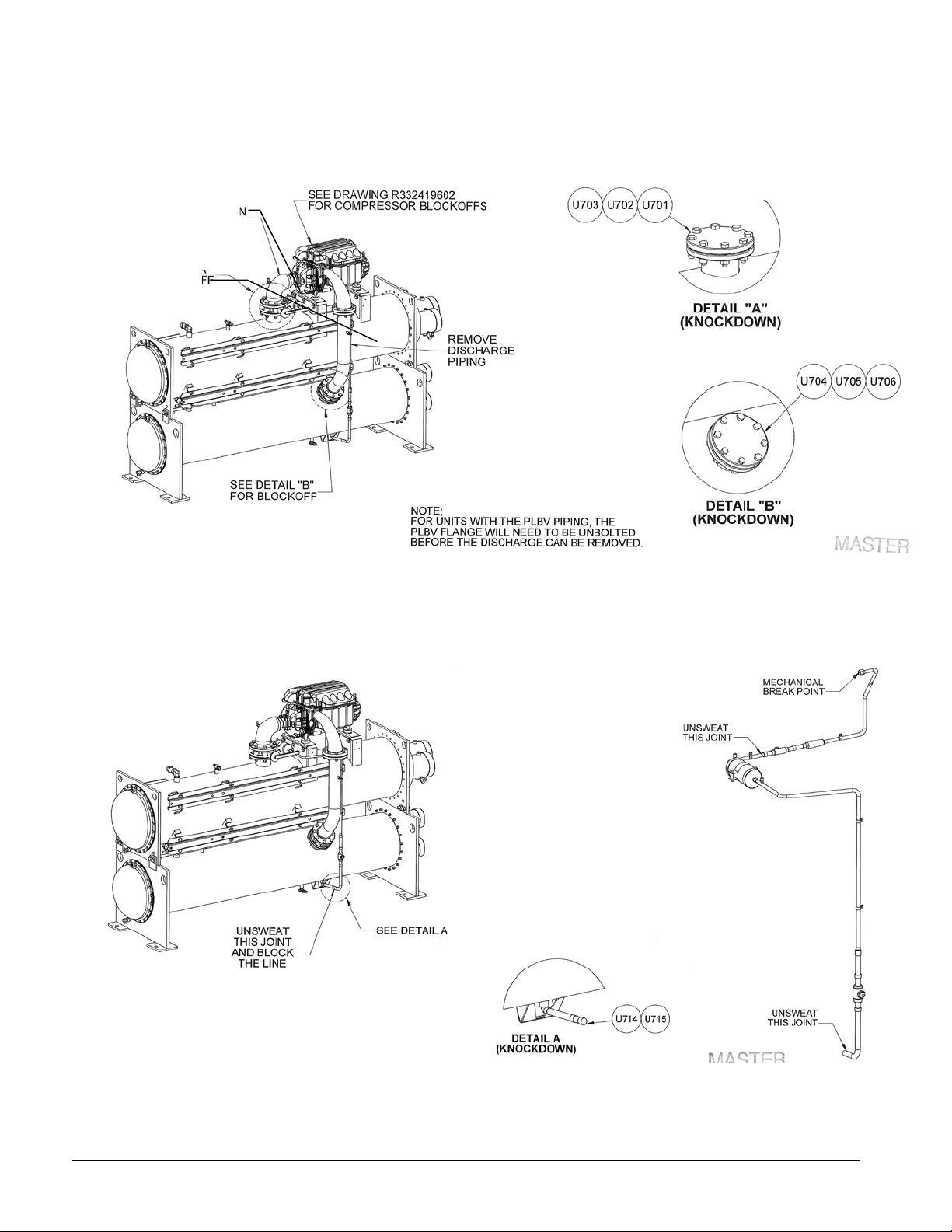
Discharge Line (2)
Figure 30, Type IV, Suction and Discharge Line Removal
Suction Line (2)
Figure 31, Type IV, Motor Cooling Line Removal
48 Field Installation Procedure IM 1128-1
Page 49

Figure 32, Type IV, Liquid Line Removal
Figure 33, Type V, Liquid line Removal
IM 1128-1 Field Installation Procedure 49
Page 50
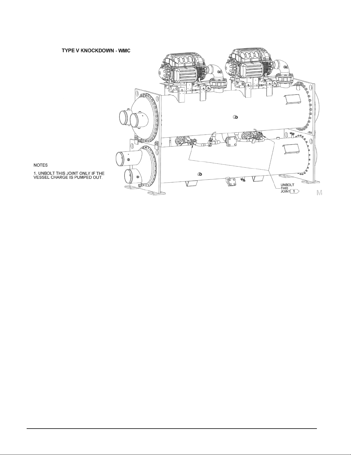
Figure 34, Type V, Vessel Separation
50 Field Installation Procedure IM 1128-1
Page 51

WME Introduction
It is estimated that fifty percent of retrofit applications require partial or complete disassembly of the
chiller. Daikin McQuay offers three solutions to the disassembly and reassembly effort on Model
WME, magnetic bearing compressor chillers.
TYPE I ... Type I provides a moderate amount of disassembly. The compressor, suction and discharge
piping, and compressor VFD power panel are removed and put on a skid. The touchscreen and
mounting arm will ship in a separate container. All associated wiring and piping will remain attached if
possible. The remaining loose parts will be packaged in a separate crate.
1. Block-offs will cover all openings on the compressor and vessels.
2. The compressor and vessels will receive a 5 psi helium holding charge.
3. The compressor will not be insulated at the factory. An insulation kit will be shipped with the unit.
4. The compressor and VFD power panel will ship loose.
5. The control panel will ship separately and have all sensors wired in, labeled and tied up. Matching label
will exist on the sensor locations.
6. The vessel stack will be insulated at the factory.
7. Suction piping insulation and glue will be shipped with the unit for field installation.
8. Refrigerant will not be shipped with the unit and must be furnished and installed by the installer.
9. All field-piping connections will be grooved mechanical couplings, O-ring face seal or copper brazing.
10. Touch-up paint and stick-on wire ties will be included.
11. The unit will undergo the rigorous, full McQuay run-test program at the factory.
12. Contact local McQuay Factory Service for price quotation and scheduling.
TYPE II ... Type II provides a total knockdown of the unit. The compressor and VFD power panel are
removed and put on a skid. The touchscreen and mounting arm will ship in a separate container. The
condenser, evaporator, and tube sheet supports will remain connected only by the attachment bolts for
easy disassembly at the job site. All wiring and piping that interconnects the components will be
removed. The remaining loose parts will be packaged in a separate crate.
1. Block-offs will cover all openings on the compressor and vessels.
2. The compressor and vessels will receive a 5 psi helium holding charge.
3. The compressor will not be insulated at the factory. An insulation kit will be shipped with the
unit.
4. Only the evaporator shell will be factory insulated. Loose insulation and glue will be shipped for
the remaining surface areas.
5. The compressor and VFD power panel will ship loose.
6. Refrigerant will be field supplied and installed.
7. All field-piping connections will be grooved mechanical couplings, O-ring face seal or copper
brazing.
8. Touch-up paint and stick-on wire ties will be included.
9. The discharge piping and suction elbow will be shipped loose in a separate crate.
10. The unit will undergo the rigorous, full Daikin McQuay run-test program at the factory.
11. Contact local McQuay Factory Service for price quotation and scheduling.
Type III ... The units are shipped fully assembled, factory charged, run-tested, insulated and painted;
ready for disassembly at the job site. Included are the vessel bolt-on connection brackets, discharge line
bolt-on flanges at the condenser. Touch-up paint and stick-on wire ties will be included. Site
disassembly and reassembly must be supervised by McQuay startup personnel. Contact local McQuay
Factory Service for price quotation and scheduling.
IM 1128-1 Field Installation Procedure 51
Page 52

Type I Reassembly
!
WARNING
TYPE I ... Type I provides a moderate amount of disassembly. The compressor, suction and discharge
piping, and compressor VFD power panel are removed and put on a skid. The touchscreen and
mounting arm will ship in a separate container. All associated wiring and piping will remain attached if
possible. The remaining loose parts will be packaged in a separate crate.
1. Block-offs will cover all openings on the compressor and vessels.
2. The compressor and vessels will receive a 5 psi helium holding charge.
3. The compressor will not be insulated at the factory. An insulation kit will be shipped with the unit.
4. The compressor and VFD power panel will ship loose.
5. The control panel will ship separately and have all sensors wired in, labeled and tied up. Matching label will
exist on the sensor locations.
6. The vessel stack will be insulated at the factory.
7. Suction piping insulation and glue will be shipped with the unit for field installation.
8. Refrigerant will not be shipped with the unit and must be furnished and installed by the installer.
9. All field-piping connections will be grooved mechanical couplings, O-ring face seal or copper brazing.
10. Touch-up paint and stick-on wire ties will be included.
11. The unit will undergo the rigorous, full Daikin McQuay run-test program at the factory.
12. Contact local McQuay Factory Service for price quotation and scheduling.
Reassembly Steps
NOTE: Additional instructions may be shown on the assembly drawings.
1. Mount the compressor on the stack. Be careful to avoid damaging lines already mounted on the
unit. Mounting bolts, washers and nuts are shipped loose. Leave the mounting bolts loose until the
suction and discharge lines are installed and aligned.
During assembly, bolts holding block-off plates (motor cooling connection, for example), are used
for reassembly of the component. See Figure 1 or Figure 2 for the location and description of the
block-offs.
2. Do not remove block-offs until ready to install piping. The compressor and vessels have a Schrader
valve on their block-off plates to be used for relieving the helium holding charge.
Remove compressor and vessel holding charge through the Schrader valve in the block-off plates
before attempting to loosen any fittings on them. Failure to do so can cause severe bodily injury.
3. Install the suction and discharge piping (see Figure 3). Before tightening the Victaulic couplings,
position the suction and discharge piping so that the compressor can be aligned to give the best fitup. When this is achieved, secure the compressor mounting bolts and proceed with installing the
Victaulics using a light coating of Victaulic lubrication.
4. Install the liquid injection line The liquid injection line is attached to the condenser and has
shipping straps securing it to the evaporator and condenser. It, and the compressor, each have a
block-off.
5. Install the motor cooling line using the same procedure as the liquid injection line.
6. Install the motor drain line (see Figure 6) using the same procedure as the liquid injection line.
52 Field Installation Procedure IM 1128-1
Page 53

7. Install compressor wiring. The wire end that has been disconnected, and its attachment point on the
compressor, will each have a label attached (VC for the vane close switch, for example) for
matching purposes.
• Guardistor, G1 (and G2 on some units), terminal box located on side of motor housing.
• Vane load/unload solenoids, SA and SB, located on the four-way solenoid assembly.
• Vane close switch, VC, located on compressor next to the discharge housing.
• Vane open switch, VO, located on suction end of compressor.
• High pressure switch, HPS, located on compressor discharge nozzle.
8. Mount the VFD power panel on the brackets in the front of the unit and interconnect to the
compressor motor using the cables provided. Control wiring will also be required. The field wiring
diagram located on the control panel door should also be consulted.
9. Normal procedure of leak testing, triple evacuation, and charging with refrigerant and lubricant
must be followed prior to the start up procedure.
10. After leak testing, insulate the compressor motor, suction line, and other miscellaneous areas with
the included insulation and adhesive. The following components should be insulated:
Evaporator Evaporator water heads Expansion valve
Motor cooling lines Suction elbow VFD cooling line
Stator cooling line Evaporator tube sheets
This completes the reassembly procedure.
Type II Reassembly
TYPE II ... Type II provides a total knockdown of the unit. The compressor and VFD power panel
are removed and put on a skid. The touchscreen and mounting arm will ship in a separate container.
The condenser, evaporator, and tube sheet supports will remain connected only by the attachment
bolts for easy disassembly at the job site. All wiring and piping that interconnects the components
will be removed. The remaining loose parts will be packaged in a separate crate.
1. Block-offs will cover all openings on the compressor and vessels.
2. The compressor and vessels will receive a 5 psi helium holding charge.
3. A compressor insulation kit will be shipped with the unit.
4. Only the evaporator shell will be factory insulated. Loose insulation and glue will be shipped
for the remaining surface areas.
5. The compressor and VFD power panel will ship loose.
6. Refrigerant will be field supplied and installed.
7. All field-piping connections will be grooved mechanical couplings, O-ring face seal or copper
brazing.
8. Touch-up paint and stick-on wire ties will be included.
9. The discharge piping and suction elbow will be shipped loose in a separate crate.
10. The unit will undergo the rigorous, full Daikin McQuay run-test program at the factory.
11. Contact local McQuay Factory Service for price quotation and scheduling.
IM 1128-1 Field Installation Procedure 53
Page 54

EVAPORATOR
TUBE SHEET
TUBE SHEET
SUPPORT
PLATE
CONDENSER
TUBE SHEET
BOLTED
BOLTED
WELDED
TWO ANGLE PLATES,
ONE WELDED TO EVAP.
ONE WELDED TO COND.
THEN BOLTED TOGETHER.
Reassembly Steps
!
WARNING
NOTE: Additional instructions may be shown on the assembly drawings.
The Type II arrangement is shipped with the evaporator, condenser, tube and sheet support plate bolt ed
together. This provides structural support during transit and also allows several options for
disassembly.
Figure 35, Component Disassembly
In most cases for narrow entry, the condenser will be
separated by unbolting it from the evaporator angle
bracket and from the tube sheet support plate. This
leaves the evaporator and the support plate that has
the mounting foot extended under where the
condenser used to be. Therefore, the evaporator is
usually unbolted from the two support plates, which
can then be more easily handled by themselves.
Remove compressor and vessel holding charge through the Schrader valve in the block-off plates
before attempting to loosen any fittings on them. Failure to do so can cause severe bodily injury.
11. Disassemble the unit to the e xtent required by the site conditions. Rig the components to their final
location and reassemble them using the fasteners that came with the unit.
12. The compressor and its suction and discharge piping should be installed on the stack before any other
lines are attached. Mount t he compressor on the stack. Mounting bolts, washers and nuts are shipped
loose. Leave the mounting bolts l oose until the suction and discharge lines are in place and aligned.
Install the suction and discharge piping. Before tightening the grooved mechanical couplings, position
the suction and discharge piping so that the compressor can be aligned to give the best fit-up. When this
is achieved, secure the compressor mounting bolts and proceed with inst alling the grooved mechanical
using a light coating of lubricant. See Figure 3.
13. Install the liquid line using Figure 11 as a guide. Due to the variety of vessel combinations available,
variation on specific units will occur.
14. Install the motor cooling line using Figure 5 as a guide.
15. Install the liquid injection line (see Figure 4). Note that any given injection line may be configured
somewhat differently than shown on the drawing.
16. Install the four-way solenoid valve assembly on the compressor suction housing.
17. Install the control panel; the unit panel is on top of the condenser. Wire and sensor leads have been
disconnected at their terminus and labele d. They remain connected at the panel and rolled up. Their
destinations have matching labels, which simplifies the installation. :
54 Field Installation Procedure IM 1128-1
Compressor panel detail ........................................ Figure 18
Unit panel wiring and connections ........................ Figure 15
Page 55

Unit panel detail .....................................................Figure 19
Unit panel sensor locations ....................................Figure 16 and Figure 17
Flow switch wiring detail ......................................Figure 20
18. The VFD as unit mounted on the condenser with brackets for mounting it and interconnection cables to
the compressor motor. Control wiring as shown in Figure 9 will also be required.
Normal procedure of leak testing, triple evacuation, and charging with refrigerant and lubricant must be
followed prior to the start up procedure.
19. Insulate the compressor, suction line, and other miscellaneous areas with the included insulation and
glue after leak testing. See Field Insulation Guide on page 29.
This completes the reassembly procedure.
IM 1128-1 Field Installation Procedure 55
Page 56

Type III Reassembly
!
DANGER
!
CAUTION
!
CAUTION
in.
mm
lbs
kg
E3612 Evaporator
171 x 48 x 44
4329 x 1222 x 1120
6840
3099
Control Panel
17 x 7 x 17
432 x 178 x 432
75
33
Description
TYPE III: T he unit ships fully assembled and charged and is field ready to knockdown as required
after refrigerant is pumped down or removed. Included are the vessel bolt-on connection brackets and
the discharge stack bolt-on flanges at the condenser.
1. The unit is shipped fully charged with refrigerant.
2. The unit will be factory insulated and painted.
3. All electrical and sensor wiring will be fastened as usual.
4. The VFD will be installed.
5. Touch up paint and stick on wire ties will be included.
6. This unit will be fully tested at the factory.
7. Labels will be provided with the instructions to mark piping, electrical wiring and sensor wiring.
Reassembly Steps
Type III units offer a variety of disassembly opportunities. In some cases the condenser and tube
support plate are removed to meet narrow entrance requirements. The compressor and VFD power
panel may be removed for low height situations. Other possibilities exist.
Therefore it is difficult to prescribe step-by-step procedures. Various secti ons of this manual can be
used where applicable, bearing in mind that the unit is fully charged with refrigerant.
Prior to un-sweating any connection in the field, verify there is no pressure or charge in the
component or lines. Failure to do so can cause severe injury or dearth.
Avoid applying excessive heat to valve seats when brazing or removing lines. Use cooling on valve
components. Failure to do so will cause valve damage.
Cover any opening to prevent foreign objects from entering. Failure to do so can cause equipment
damage.
Table 9, Major Component Dimensions and Weights
Chiller
WME 500
WME 700
Component
E3012 Evaporator 169 x 43 x 38 4292 x 1081 x 955 5075 2299
C2612 Condenser 165 x 36 x43 4181 x 915 x 1080 3900 1767
C3012 Condenser 169 x 42 x 46 4292 x 1065 x 1170 5333 2416
Compressor 35 x 45 x 20 889 x 1143 x 508 750 340
M2 VFD Power Panel 41 x 21 x 61 1035 x 533 x 1545 1850 804
M3 VFD Power Panel 54 x 24 x 60 1370 x 610 x 1523 2750 1197
Control Panel 17 x 7 x 17 432 x 178 x 432 75 33
E3612 Evaporator 171 x 48 x 44 4329 x 1222 x 1120 6840 3099
C3012 Condenser 169 x 42 x 46 4292 x 1065 x 1170 5333 2416
C3612 Condenser 173 x 48 x 52 4394 x 1219 x 1321 7508 3401
Compressor 35 x 46 x 28 889 x 1168 x 711 770 350
M4 VFD Power Panel 54 x 24 x 60 1370 x 610 x 1523 2750 1197
Dimensions L x W x H Dry Weight
56 Field Installation Procedure IM 1128-1
Page 57

Knockdown Dimensions
in (mm)
in (mm)
in (mm)
in (mm)
in (mm)
in (mm)
Line , Suction Elbow Removed (Note 2)
Panels, Raceway, Compressor Removed
Panels, Raceway, Removed
(2510)
(2662)
B
C
A
Figure 36, WME 0500 Chiller Height with Components Removed
WME 500 WME 700
Vessel Size/ Motor Code >>
E3012
C2612
M2
E3012
C2612
M3
E3612
C3012
M2
E3612
C3012
M3
E3612
C3012
M4
E3612
C3612
M4
A To Top of Compressor Brackets
Panels, Raceway, Compressor, Discharge
B To Top of Discharge Flange
C To Top of Compressor
Total Unit height, No Components Removed
NOTES:
1. See specific unit dimension drawing for balance of dimensions.
2. The compressor mounting bracket is higher than the top of the evaporat or tube sheet. This
knockdown arrangement is the lowest unit height without separating the vessels.
62.0
(1575)
68.4
(1737)
85.5
(2171)
95.3
(2421)
62.0
(1575)
68.4
(1737)
85.5
(2171)
94.8
(2408)
69.8
(1773)
76.2
(1935)
91.3
(2319)
99.3
(2522)
69.8
(1773)
76.2
(1935)
91.3
(2319)
98.8
(2510)
69.8
(17730
81.0
(2058)
92.5
(2350)
98.8
75.6
(1920)
86.7
(2203)
98.3
(2497)
104.8
IM 1128-1 Field Installation Procedure 57
Page 58
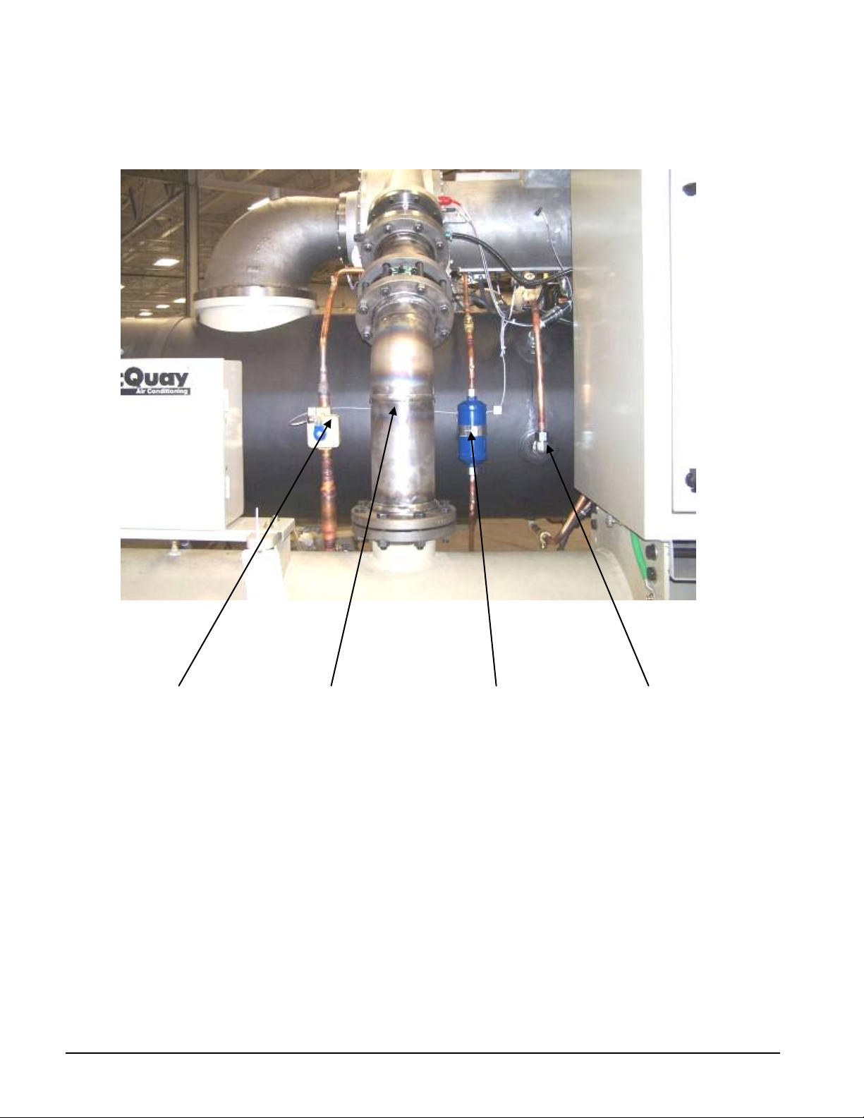
Piping Removal
Valve
Figure 37, Refrigerant Piping to Compressor
Liquid
Injection
Supply
Discharge
Line and
Check
Stator
Cooling
Supply
Stator
Cooling
Return
58 Field Installation Procedure IM 1128-1
Page 59
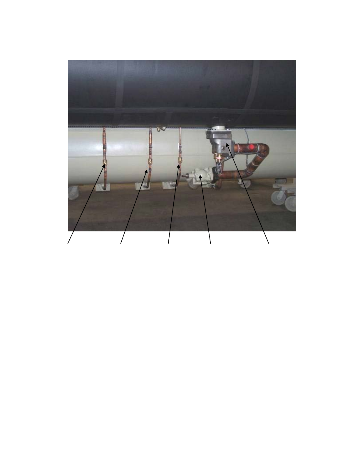
Figure 38, Refrigerant Pipi ng f r om Condenser
VFD Cooling
Supply,
Connected to
VFD Panel
Rotor
Cooling
Supply
Stator
Cooling
Supply
King
Valve
Expansion Valve
with Liquid
Injection S upply
Line Behind
IM 1128-1 Field Installation Procedure 59
Page 60

Figure 39, Refrigerant Connections at Compressor
Stator
Cooling
Supply
Rotor
Cooling
Return
Rotor Cooling
Supply
Figure 40, Electric Connections at Com pressor
Power
300Vdc
Voltage and
Logic
Ethernet Low
Compressor
Wire Harness
60 Field Installation Procedure IM 1128-1
Page 61

Figure 41, Liquid Injecti on Pi pi ng
Figure 42, Stator Cooling Piping
IM 1128-1 Field Installation Procedure 61
Page 62
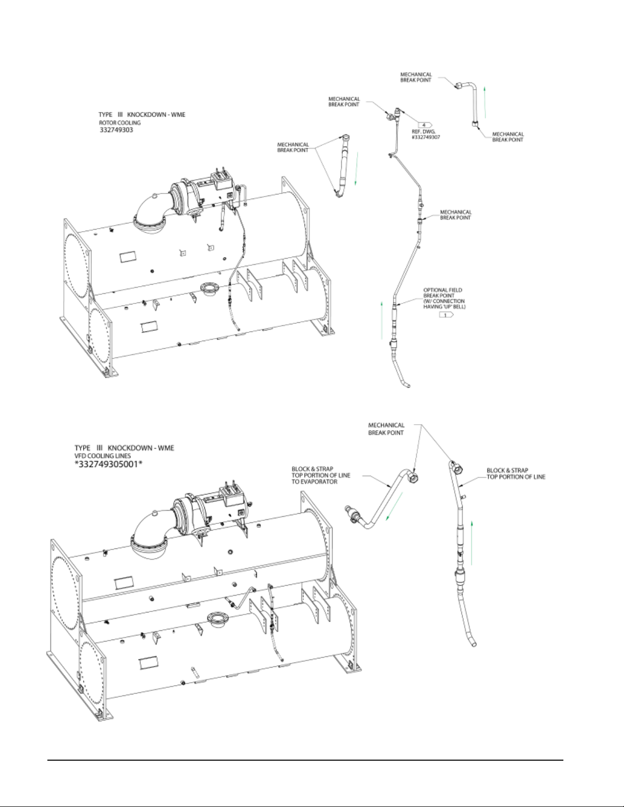
Figure 43, Rotor Cooling Lines
Figure 44, VFD Cooling Piping
62 Field Installation Procedure IM 1128-1
Page 63

Compressor Removal and Re-Attachment
Figure 45, Compressor Removal/Re-Att achm ent , View #1
Figure 46, Compressor Removal/Re-Attachm ent , View #2
IM 1128-1 Field Installation Procedure 63
Page 64
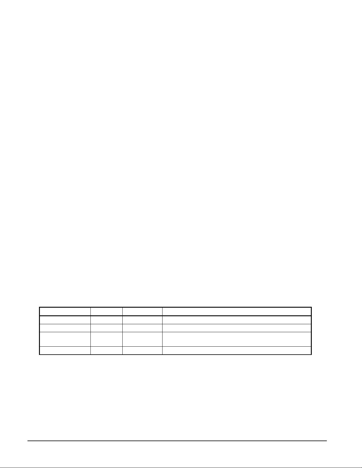
Part No.
Quantity
Description
Unit Location
350233017
1
“O” Ring
Between suction nozzle and evaporator outlet flange
pipe flange(Note 1)
735073620
1
“O” Ring
Between the compressor volute and the discharge nozzle.
Compressor Removal and Re-Attachment
Removal Preparation
1. Close the king valve at condenser liquid line outlet.
2. Close all other related shut-off valves.
3. Pump the refrigerant charge down into the condenser.
4. Ensure that the charge has been removed from the compressor and evaporator and that the discharge
check valve is holding the charge in the condenser.
5. Loosen and remove bolts on either side of the compressor discharge nozzle (see Figure 46, flag #1).
Compressor Removal
1. Loosen and remove bolts on either side of the cast suction elbow (see Figure 45, flag #2).
2. Remove rotor cooling return line on the underside of the compressor motor housing along with both
rotor cooling supply lines per Figure 43 noted as "mechanical break points”, and Figure 39,
3. Remove (2) DIN connectors from the solenoid coils (see flag #3 on Figure 41 and Figure 42).
4. Remove rotor stepping valve control wire ( see flag #4 on Figure 43).The wire ties will have to be cut
away during this process.
5. The following wires coming from the VFD will need to be removed (Figure 40):
- 300v dc power supply ( yellow cable )
- 25 pin "D" shell connector
- power leads on the top of the motor housing
- Ethernet cable coming from the unit control box
6. Remove the wireway box assembly from the compressor to the back of the VFD.
7. Loosen the (4) bolts from the compressor's bottom mounting feet see Figure 45, flag #5). Do not
loosen or remove bolts securing the compressor brackets as height is pre-set from the factory.
8. Mount a 1/2-13 swivel lifting eye to the front tapped lif ti ng hole on the compressor motor housing. (see
Figure 45, flag #6). The compressor weight is 1000 lbs.
Compressor Re-Attachment
The following gaskets and “O” rings required for compressor reassembly are shipped loose:
Table 10, WME 500 Type III Knockdown “O” Rings and Gaskets
070194992 1 “O” Ring Between suction nozzle and compressor inlet connection
070199039 1 Gasket
Notes:
1. There are four identical gaskets for the discharge pipe, all are not used.
2. Blank-off plates not shown but may be required for extended aperture opening. The discharge nozzle is the short
section of pipe with fittings between the compressor volute and the discharge pipe.
1. Set the suction elbow back on top of the evaporator and install the screws loosely at the evaporator
flange, being sure to inspect the O-rings for damage and replace if needed.
Between compressor discharge nozzle and upper discharge
2. Set compressor on mounting brackets and install the (4) mounting bolts loosely. Install the gasket at
check valve and insert bolts through the spool piece.
64 Field Installation Procedure IM 1128-1
Page 65

3. Install (12) bolts at elbow to compressor and torque to 25 ft-lbs; do not over-tighten.
4. Install (18) bolts at evaporator flange to the suction line and torque to 62 ft-lbs; do not over-tighten.
5. Torque the (8) bolts to the spool piece at the check valve to 205 ft-lbs.
6. Re-install the wireway between the compressor and the VFD.
7. Re-attach all associated power wiring & Ethernet cable.
8. Evacuate the evaporator and VFD cooling lines to 300 microns for one hour.
9. Open all valves.
10. Perform refrigerant leak check to ensure all connections and fittings are securely fastened.
IM 1128-1 Field Installation Procedure 65
Page 66

66 Field Installation Procedure IM 1128-1
Page 67

Page 68

McQuay International Training and Development
Now that you have made an investment in modern, efficient Daikin McQuay equipment, its care should
be a high priority. For training information on all Daikin McQuay HVAC products, please visit us at
www.daikinmcquay.com and click on training, or call 540-248-9646 to speak to the Training
Department.
Warranty
All Daikin McQuay equipment is sold pursuant to McQuay International standard terms and conditions
of sale, including Limited Product Warranty. Consult your local Daikin McQuay Representative for
warranty details. To find your local Daikin McQuay Representative, go to www.daikinmcquay.com.
This document contains the most current product information as of this printing. For the most up-todate product information, please go to www.daikinmcquay.com.
2012 McQuay International • (800) 432-1342 • www.daikinmcquay.com
IM 1128-1 (4/12)
 Loading...