

Page 1
Installation and Maintenance Manual
IMM WMC-2
Group: Chiller
Part Number: 331374601
Effective: November 2007
Supersedes: August 2007
Water-Cooled Centrifugal Chiller
With Oil-Free Magnetic Bearing Compressors
Model WMC-145S to 290D (50/60 Hertz)
R-134a
Page 2
Table of Contents
Introduction...........................................3
................................................ 3 Nomenclature
Installation.............................................4
................................ 4 Receiving and Handling
Location and Mounting ........................5
.................................................. 5 Water Piping
.............................................. 8 Field Insulation
Physical Data and Weights
............................ 8
DimensionsError! Bookmark not defined.
Dimensions.............................................9
Pressure Drop Curves.........................16
Relief Valves.........................................17
Electrical Data.....................................19
............................................... 19 Power Wiring
WMC 145S, Single Compressor
System Pumps
.............................................. 25
.............................. 22 Single Point Connection
................. 20
........ 20 WMC 145D, 150D Dual Compressors
..... 21 WMC250D and 290D Dual Compressor
....................... 24 Use with On-Site Generators
................................... 25 VFD Line Harmonics
.................................. 28 Multiple Chiller Setup
............................. 30 Prestart System Checklist
Operation .............................................31
............................. 31 Operator Responsibilities
Compressor Operation
................................. 31
......................................... 31 Operating Limits:
................................... 32 MicroTech II Control
Building Automation Systems ............33
Capacity Control System
............................................. 36 Surge and Stall
............................. 35
................... 36 Normal Unit Startup/Shutdown
.................... 37 Annual Unit Startup/Shutdown
Maintenance ........................................38
......................... 38 Pressure/Temperature Chart
Routine Maintenance
................................... 38
.......................................... 39 Repair of System
Maintenance Schedule ........................42
Service Programs ................................43
Operator Schools.................................43
Limited Warranty ...............................43
*
*Unit Controllers are LonMark certified with an optional LonWorks communication module.
Manufactured in an ISO Certified Facility
Document: Catalog WMC-4
Issue Date: August 2007
Replaces: Catalog WMC-2
©2007 McQuay International. Illustrations and data cover the McQuay International product at the time of publication and we reserve the
right to make changes in design and construction at anytime without notice. ™® The following are trademarks or registered trademarks of
their respective companies: BACnet from ASHRAE;
used by L
from AST ElectroFin Inc.; Modbus from Schneider Electric; FanTrol, MicroTech II, Open Choices, and SpeedTrol from McQuay
International.
ONMARK International under a license granted by Echelon Corporation; Compliant Scroll from Copeland Corporation; ElectroFin
LONMARK, LonTalk, LONWORKS, and the LONMARK logo are managed, granted and
2 Centrifugal Chillers IMM WMC-2
Page 3
Introduction
General Description
The McQuay Model WMC Centrifugal Water Chillers are complete, self-contained, automatically controlled,
fluid-chilling units featuring oil-free, magnetic bearing compressors. Each unit is completely assembled and
factory tested before shipment.
The WMC chillers are equipped with two compressors operating in parallel with a single evaporator and single
condenser. The model WMC 145S has a single compressor.
The chillers use refrigerant R-134a that operates at a positive pressure over the entire operation range, so no
purge system is required.
The controls are pre-wired, adjusted and tested. Only normal field connections such as water piping, relief valve
piping, electric power and control interlocks are required, thereby simplifying installation and increasing
reliability. Necessary equipment protection and operating controls are included.
All McQuay centrifugal chillers are factory-tested prior to shipment and must be commissioned by a factorytrained McQuay service technician. Failure to follow this startup procedure can affect the equipment warranty.
The standard limited warranty on this equipment covers parts that prove defective in material or workmanship.
Specific details of this warranty can be found in the warranty statement furnished with the equipment.
Cooling towers used with McQuay centrifugal chillers are normally selected for condenser water inlet water
temperatures between 75°F and 90°F (24°C and 32°C). Lower entering water temperatures are desirable from
the standpoint of energy reduction, but a minimum does exist. For recommendations on optimum entering water
temperature and cooling tower fan control, consult the “Condenser Water” section on page
7.
Nomenclature
W M C 290 D
Centrifugal Compressor
Dangers indicate a hazardous situation which will result in death or serious injury if not avoided.
Warnings indicate potentially hazardous situations, which can result in property damage, severe
Water-cooled
Magnetic Bearings
D=Dual Compressors
S=Single Compressor
Nominal Tons
HAZARD IDENTIFICATION INFORMATION
! DANGER
! WARNING
personal injury, or death if not avoided.
! CAUTION
Cautions indicate potentially hazardous situations, which can result in personal injury or
equipment damage if not avoided.
IMM WMC-2 Centrifugal Chillers 3
Page 4
Installation
t
Receiving and Handling
The unit should be inspected immediately after receipt for possible damage.
All McQuay centrifugal water chillers are shipped FOB factory and all claims for handling and shipping damage
are the responsibility of the consignee.
On units with factory-installed insulation, the insulation is removed from the vessel lifting hole (also used for
transportation tie-downs) locations and are shipped loose. They should be glued in place after the unit is finally
placed. Neoprene vibration pads are also shipped loose. Check that these items have been delivered with the
unit. They are usually placed in a control panel.
If so equipped, leave the shipping skid in place until the unit is in its final position. This will aid in handling the
equipment.
Extreme care must be used when rigging the unit to prevent damage to the control panels and refrigerant piping.
See the certified dimension drawings included in the job submittal for the center of gravity of the unit. If the
drawings are not available, consult the local McQuay sales office for assistance.
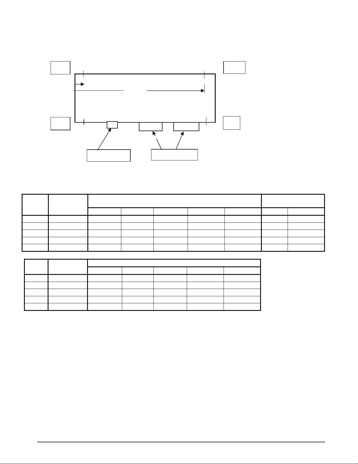
The unit can be lifted by fastening the rigging hooks to the four corners of the unit where the rigging eyes are
located (see
panels, piping and electrical panels.
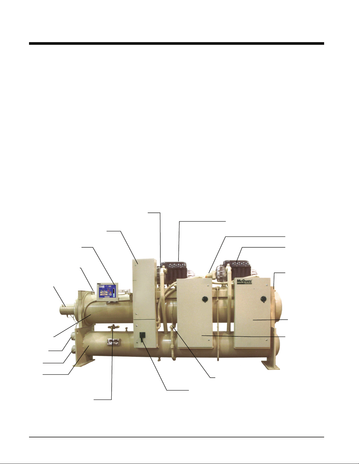
Figure 1, WMC-D, Major Component Locations
Figure 1). Spreader bars must be used between the rigging lines to prevent damage to the control
Combined Discharge
Check and Shutoff Valve
Control Panel
Compressor #1
Suction Shutoff Valve
Touch Screen, OITS
Evaporator Relief Valve
Outle
Evaporator
Outlet
Inlet
Condenser
Condenser
Relief Valves
Compressor #2 Operator Interface
Rigging Holes
Each Corner
Circuit #2
Power Panel
Circuit #1
Power Panel
Electronic Expansion Valve
Optional Single-Point
Power Block or
Disconnect Switch
4 Centrifugal Chillers IMM WMC-2
Page 5

Location and Mounting
Clearance
The unit must be mounted on a level concrete or steel base and must be located to provide service clearance at
one end of the unit for possible removal of evaporator and/or condenser tubes. Evaporator and condenser tubes
are rolled into the tube sheets to permit replacement if necessary. The length of the vessel should be allowed at
one end. Doors or removable wall sections can be utilized. Clearance at all sides, including the top, is 3 feet (1
meter). The U.S. National Electric Code (NEC) or local codes can require more clearance in and around
electrical components (4-feet in front of electrical panels) and must be checked for compliance.
Vibration Pads
The shipped-loose neoprene vibration pads (shipped in the power panels) should be located under the corners of
the unit (unless the job specifications state otherwise). They are installed to be flush with the sides and outside
edge of the feet.
Insulation Corners
Insulation corners that cover the rigging holes on the upper corners of the vessel end plates are shipped loose (in
the power panels) and should be installed with adhesive after the init is set in place.
Mounting
Make sure that the floor or structural support is adequate to support the full operating weight of the complete
unit.
It is not necessary to bolt the unit to the mounting slab or framework; but should this be desirable, 1-1/8" (28.5
mm) mounting holes are provided in the unit support at the four corners.
Note: Units are shipped with refrigerant valves closed to isolate the refrigerant in the unit condenser.
Valves must remain closed until start-up by the McQuay technician.
Nameplates
There are several identification nameplates on the chiller:
• The unit nameplate is located on the Unit Control Panel. It has a Model No. XXXX and Serial No. XXXX.
Both are unique to the unit and will identify it. These numbers should be used to identify the unit for service,
parts, or warranty questions. This plate also has the unit refrigerant charge.
• Vessel nameplates are located on the evaporator and condenser. Along with other information, they have a
National Board Number (NB) and a serial number, either of which identify the vessel (but not the entire
unit).
Water Piping
Vessel Drains at Start-up
The unit is tilted and drained of water in the factory and shipped with open drain valves in each head of the
evaporator and condenser. Be sure to close the valves prior to filling the vessel with fluid.
Evaporator and Condenser Water Piping
All evaporators and condensers come standard with groove-type nozzles for Victaulic couplings (also suitable for
welding), or optional flange connections. The installing contractor must provide matching mechanical
connections of the size and type required.
! CAUTION
Freeze Notice: Neither the evaporator nor the condenser is self-draining; both must be blown out
to help avoid damage from freezing temperatures.
IMM WMC-2 Centrifugal Chillers 5
Page 6
The piping should include thermometers at the inlet and outlet connections and air vents at the high points.
The water heads can be interchanged (end for end) so that the water connections can be made at either end of the
unit. If this is done, use new head gaskets and relocate the control sensors.
In cases where the water pump noise can be objectionable, vibration isolation sections are recommended at both
the inlet and outlet of the pump. In most cases, it will not be necessary to provide vibration eliminator sections in
the condenser inlet and outlet water lines. But they can be required where noise and vibration are critical.
Important Notes on Welding
If welding is to be performed on the mechanical or flange connections:
1. Remove the solid-state temperature sensor, thermostat bulbs and optional nozzle mounted flow switches (if so
equipped) from the wells to prevent damage to those components.
2. Properly ground the unit or severe damage to the MicroTech II® unit controller can occur.
Note: ASME certification will be revoked if welding is performed on a vessel shell or tube sheet.
Water pressure gauge connection taps and gauges must be provided in the field piping at the inlet and outlet
connections of both vessels for measuring the water pressure drop. The pressure drops and flow rates for the
various evaporators and condensers are job specific and the original job documentation can be consulted for this
information. Refer to the nameplate on the vessel shell for identification.
Connections
Be sure that water inlet and outlet connections match certified drawings and stenciled nozzle markings. The
condenser is connected with the coolest water entering at the bottom connection to maximize subcooling. The
evaporator outlet is on the side of the unit with the two power panels, regardless of which end the connections are
on. See
Figure 1.
! CAUTION
When common piping is used for both building heating and cooling modes, care must be taken to
provide that water flowing through the evaporator cannot exceed 110°F. Water this hot can cause the
relief valve to discharge refrigerant or damage controls.
Piping must be supported to eliminate weight and strain on the fittings and connections. Chilled water piping
must be adequately insulated. A cleanable 20-mesh water strainer must be installed in both water inlet lines.
Sufficient shutoff valves must be installed to permit draining the water from the evaporator or condenser without
draining the complete system.
Flow Switch
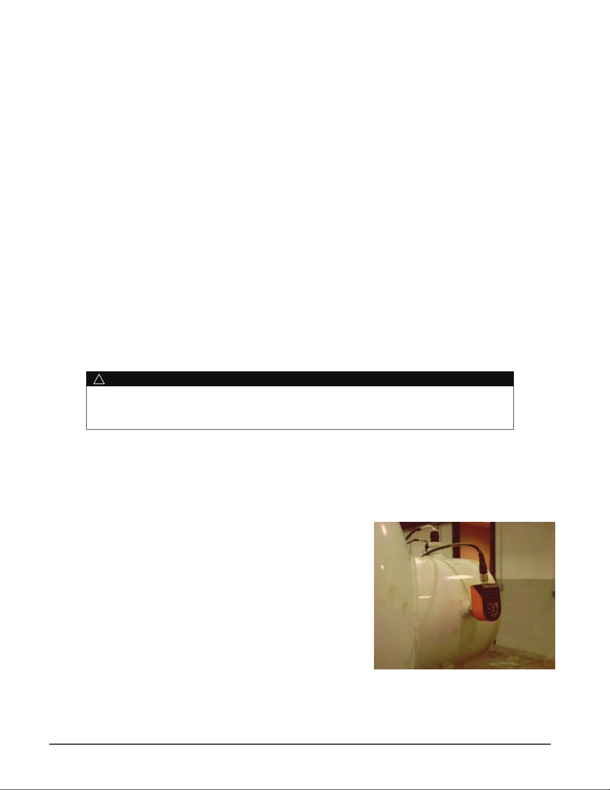
Figure 2, Unit-Mounted Flow Switch
Note: Chiller units must have flow switches for the evaporator and
condenser. McQuay furnishes factory-installed and wired, thermaltype flow switches as standard equipment on WMC chillers. Fieldinstalled and wired Delta-P switches can be used instead.
They prevent the unit from starting without sufficient water flow
through the vessels. They also serve to shut down the unit in the
event that water flow is interrupted to guard against evaporator
freeze-up or excessive discharge pressure.
Additionally, for a higher margin of protection, normally open
auxiliary contacts in the pump starters can be wired in series with
the flow switches as shown in the Field Wiring Diagram on page
23.
6 Centrifugal Chillers IMM WMC-2
Page 7
Cooling Towers
The condenser water flow rate must be checked to be sure that it conforms to the system design. A tower bypass
valve, controlled by the unit controller, is required to control the minimum condenser entering temperature.
Unless the system and chiller unit are specifically designed for them, condenser bypass or variable condenser
flow is not recommended, since low condenser flow rates can cause unstable operation and excessive tube
fouling.
Condenser Water Temperature
When the ambient wet bulb temperature is lower than design, the entering condenser water temperature can be
allowed to fall, improving chiller performance.
McQuay chillers will start with entering condenser water temperature as low as 55°F (12.8°C) providing the
chilled water temperature is below the condenser water temperature.
Depending on local climatic conditions, using the lowest possible entering condenser water temperature can be
more costly in total system power consumed than the expected savings in chiller power would suggest due to the
excessive fan power required.
To obtain lower than 55°F (12.8°C) entering condenser water temperature with a tower selected to produce 85°F
(29.4°C) water temperature at design ambient air temperatures, cooling tower fans must continue to operate at
100% capacity at low wet bulb temperatures. As chillers are selected for lower kW per ton, the cooling tower fan
motor power becomes a higher percentage of the peak load chiller power. The offsets of compressor power and
fan power must be examined. On the other hand, the low condenser water temperatures can be easy and
economical to achieve in mild climates with low wet bulb temperatures.
Even with tower fan control, some form of water flow control such as tower bypass must be used and controlled
by the chiller MicroTech II controller.
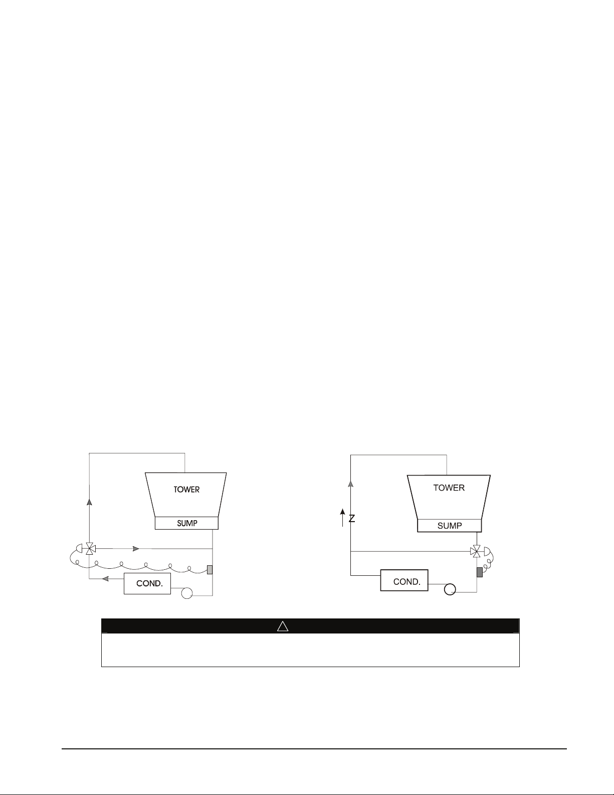
Figure 3 and Figure 4 illustrate two temperature-actuated tower bypass arrangements. The “Cold Weather”
scheme, Figure 4, provides better startup under cold ambient air temperature conditions. The check valve may be
required to prevent air at the pump inlet.
Figure 3, Tower Bypass, Mild Weather Operation
! CAUTION
Tower water treatment is essential for continued efficient and reliable unit operation. If not
available in-house, competent water treatment specialists should be contracted.
Figure 4, Tower Bypass, Cold Weather Operation
IMM WMC-2 Centrifugal Chillers 7
Page 8
Field Insulation
If the optional factory-installation of thermal insulation is not ordered, insulation should be field installed to
reduce heat loss and prevent condensation from forming. Insulation should cover the evaporator barrel, tube
sheet, and water heads, plus the suction line to the compressor flange and the compressor end bell opposite the
suction connection.
The optional factory-installed insulation of cold surfaces includes the evaporator and non-connection water
head, suction piping, compressor inlet, and motor housing.
Insulation is UL recognized (File # E55475). It is 3/4" thick ABS/PVC flexible foam with a skin. The K
factor is 0.28 at 75°F. Sheet insulation is fitted and cemented in place forming a vapor barrier, then painted
with a resilient epoxy finish that resists cracking.
The insulation complies to or has been tested in accordance with the following:
ASTM-C-177 ASTM-C-534 Type 2 UL 94-5V
ASTM-D-1056-91-2C1 ASTM E 84 MEA 186-86-M Vol. N
CAN/ULC S102-M88
Physical Data and Weights
Evaporator
Refrigerant-side design pressure is 200 psi (1380 kPa). Water-side is 150 psi (1034 kPa).
Approximate total square footage of insulation surface required for individual packaged chillers is tabulated by
evaporator code and can be found below. The suction elbow and compressor also require insulation.
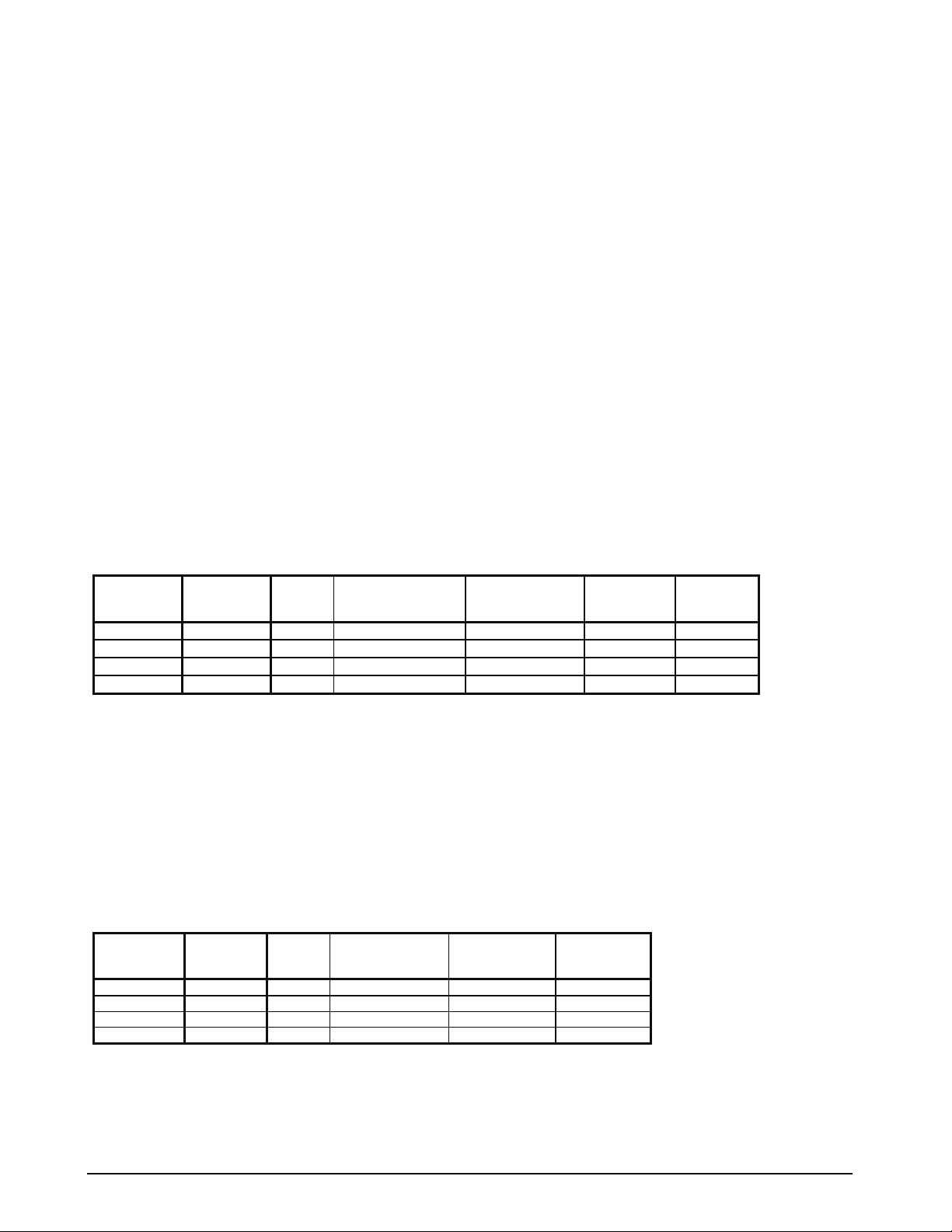
Table 1, Evaporator Physical Data
2
)
Number of
Relief
Valves
WMC Model
145S, 145D E2209
150D E2212
250D E2609
290D E2612
Notes:
1. Refrigerant charge is for the entire unit and is approximate since the actual charge will depend on other variables. Actual charge will
be shown on the unit nameplate.
2. Water capacity is based on standard tube configuration and standard dished heads.
Evaporator Tube
Code Length
9 ft. 590 (268) 38 (145) 66 (6.1) 1
12 ft. 790 (358) 45 (170) 90 (8.3) 1
9 ft. 850 (386) 61 (231) 76 (7.1) 1
12 ft. 1150 (522) 72 (273) 102 (9.4) 1
Maximum Unit
Refrigerant Charge
lb. (kg)
Evaporator
Water
Volume, gal (L)
Insulation
Area
sq. ft. (m
Condenser
With positive pressure systems, the pressure variance with temperature is always predictable, and the vessel
design and pressure relief protection are based upon pure refrigerant characteristics. R-134a requires ASME
vessel design, inspection and testing and uses spring-loaded pressure relief valves. When an over-pressure
condition occurs, spring-loaded relief valves purge only that quantity of refrigerant required to reduce the
pressure to the valve’s set pressure and then close.
Refrigerant-side design pressure is 200 psi (1380 kPa). Water-side design is 150 psi (1034 kPa).
Table 2, Condenser Physical Data
WMC Model
145S, 145D C2009
150D C2012
250D C2209
290D C2212
Notes:
1. Condenser pumpdown capacity based on 90% full at 90°F.
2. Water capacity based on standard configuration and standard heads and can be less with lower tube counts.
3. See Relief Valves section for additional information.
4. See page 8 for unit operating, shipping and corner weights.
Condenser
Code
Tube
Length
9 ft. 724 (328) 47 (147) 2
12 ft. 971 (440) 62 (236) 2
9 ft. 883 (401) 61 (231) 2
12 ft. 1174 (533) 72 (273) 2
Maximum
Pumpdown
Capacity lb. (kg)
Water
Volume
gal. (L)
Number of
Relief Valves
8 Centrifugal Chillers IMM WMC-2
Page 9
Dimensions
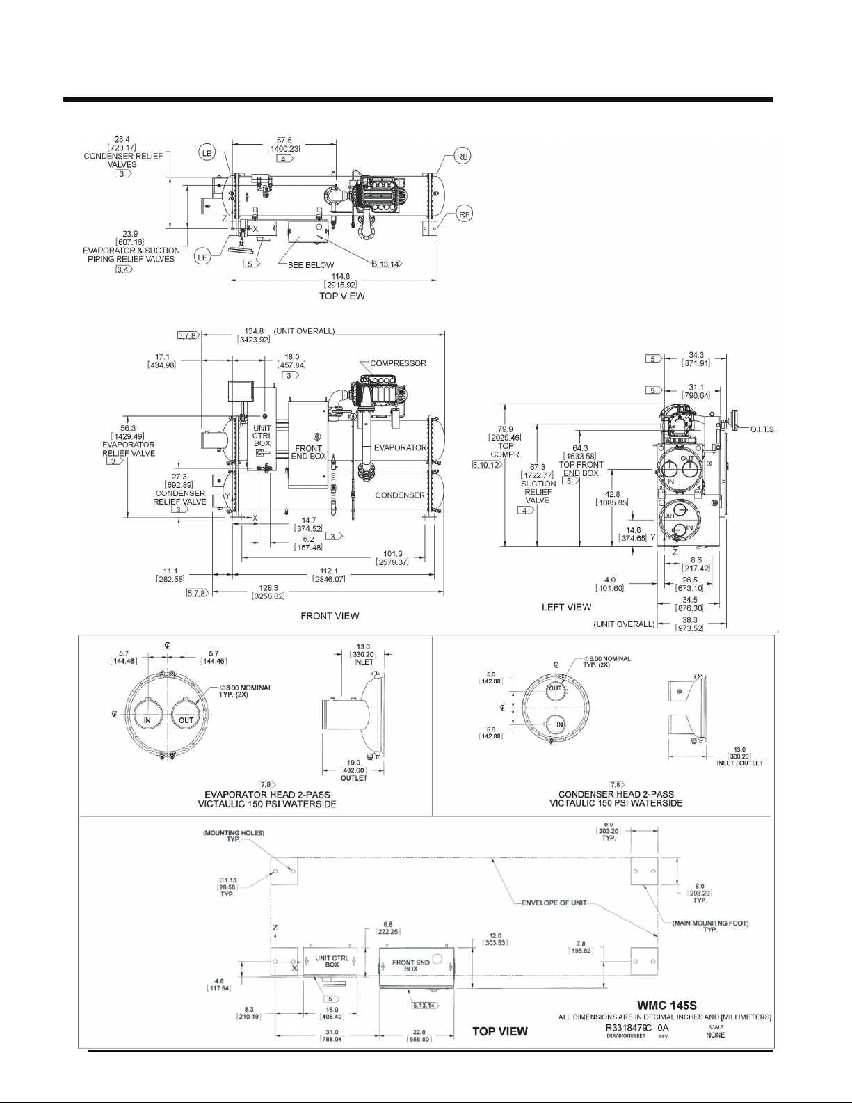
WMC 145SFigure 5, (NOTE: See page 14 for notes.)
IMM WMC-2 Centrifugal Chillers 9
Page 10
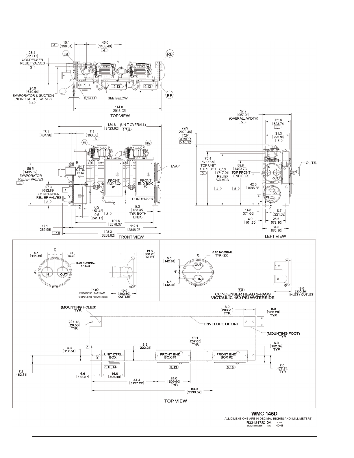
Figure 6, WMC 145D (See page 14 for notes.)
10 Centrifugal Chillers IMM WMC-2
Page 11
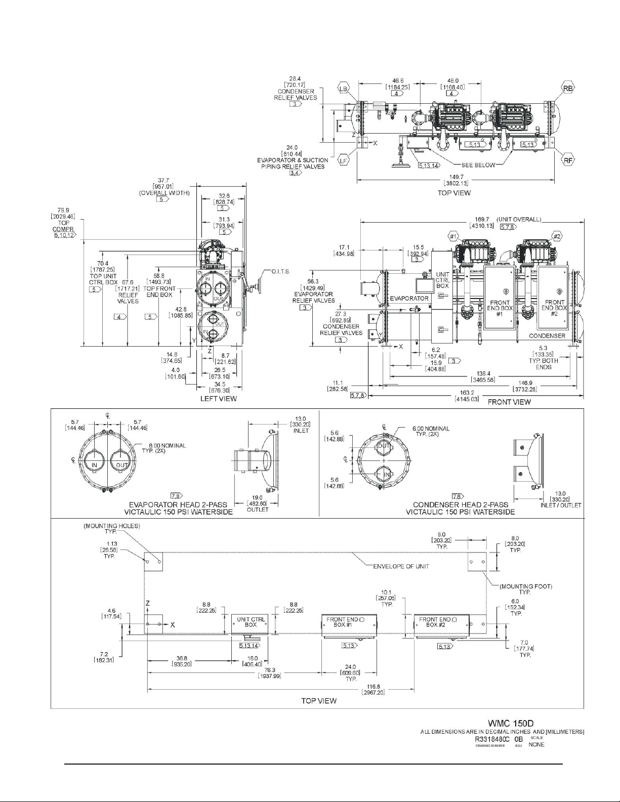
Figure 7, WMC 150D, 2-Pass Evaporator, 2-Pass Condenser ( See page 14 for notes.)
IMM WMC-2 Centrifugal Chillers 11
Page 12
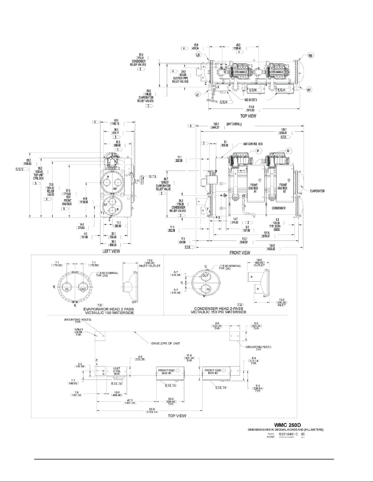
WM C 250DFigure 8, , 2-Pass Evaporator, 2-Pass Condenser
(NOTE: See page 14
for notes.)
12 Centrifugal Chillers IMM WMC-2
Page 13

Figure 9, WMC 290D, 2-Pass Evaporator, 2- Pass Condenser (See page 14 for notes.)
IMM WMC-2 Centrifugal Chillers 13
Page 14
Drawing Notes
NOTES:
1. All dimensions are in Inches and [Millimeters] unless noted otherwise.
2. Final connections must allow for .500 inch +/- [12.7mm] manufacturing tolerances.
3. 1.00-inch FPT [25.4 mm] evaporator and condenser relief valves must be piped per ANSI / ASHRAE 15.
Number of relief valves is 1 per evaporator and 2 per condenser.
4. .375 inch [9 mm] suction nozzle relief valve must be piped per ANSI / ASHRAE 15.
5. Clearances:
Ends, 108 inches (2743 mm) on WMC 145, WMC 150 with 9 foot tubes, and WMC 250
144 inches (3658 mm) on WMC 150 with 12 foot tubes and WMC 290
plus 36 inches (910) is required at either end of the tube sheet for tube maintenance. If
clearance is at the connection end, do not bloct tube access with piping, pumps, etc.
Sides 36 inches (914 mm) is recommended on all other sides and top for service clearance.
Electric Panels Most codes require 48 inches (1219 mm) clearance in front of the control boxes and electrical
panels.
6. 3.25-inch [83mm] diameter lifting holes are provided. See installation manual for lifting instructions.
7. All water connections are given in standard U.S. pipe sizes. Standard connections are suitable for welding or
victaulic couplings.
8. Unit shown has standard left-hand water connections. Right-hand connections are available for either vessel.
For right hand evaporator the inlet and outlet nozzles are reversed. ANSI-flanged connections are available upon
request. When using ANSI-flanged connections add .500 inch [13 mm] to each flanged end.
9. Dimensions shown are for units (evaporator / condenser) with standard design pressures. The refrigerant side
design pressure is 200 PSI {1380 kPa} and the waterside design pressure is 150 PSI {1034 kPa}. Consult the
factory for unit dimensions with higher design pressures.
10. The unit vibration isolator pads are provided for field installation. When fully loaded - .250 inches [6 mm]
thick.
11. These values are for units with standard wall thickness copper tubing only.
12. The shipping skid, when used, adds 4.00 inches [105 mm] to the overall unit height.
13. If main power wiring is brought up through the floor, this wiring must be outside the envelope of the unit.
14. Typical wiring connections to the compressor control box are multi-power wiring into the top of each box.
The unit control box has a lower section that contains a disconnect switch when the optional single-point
connection is selected and is the landing point for the power connection. Otherwise it is empty.
15. The unit is shipped with an operating charge of refrigerant.
16. Optional marine water box connections are available upon request.
Table 3, Overall Dimensions, 2-Pass Vessels
In. (mm)
Length
Width
Height
WMC 145S, WMC 145D WMC 150 WMC 250 WMC 290
Same End Opp. End Same End Opp. End Same End Opp. End Same End Opp. End
135 (3429) 141 (3581) 171 (4343) 177 (4496)
39 (991) 39 (991) 35 (889) 35 (889) 44 (1117) 44 (1117) 44 (1117) 44 (1117)
80 (2032) 80 (2032) 80 (2032) 80 (2032) 83 (2108) 83 (2108) 83 (2108) 83 (2108)
135 (3429)
141 (3581) 171 (4343) 177 (4496)
14 Centrifugal Chillers IMM WMC-2
Page 15
Mounting/Lifting Weights
V
V
Figure 10
LB RB
“A
“B”
LF
RF
Circuit #1
Circuit #2
Control Panel
Electric Panels
WMC
Model
145S
145D
150D
250D
290D
essel Models
(Size)
E2209/C2009 1238 (561) 1146 (520) 1565 (710) 1450 (6580 5399 (2449) 4.0 (102) 112.0 (2845)
E2209/C2209 1438 (652) 1440 (653) 1685 (765) 1688 (766) 6252 (2836) 4.0 (102) 112.0 (2845)
E2212/C2012 1619 (735) 1750 (794) 1927 (874) 2083 (945) 7380 (3347) 4.0 (102) 147.0 (3734)
E2609/C2209 1850 (839) 1829 (830) 1933 (877) 1911 (867) 7525 (3414) 4.0 (102) 112.0 (2845)
E2612/C2212 2793 (1242) 2105 (955) 3399 (1542) 2611 (1184) 10,953 (4923) 4.0 (102) 147.0 (3734)
LF RF LB RB Total “A” “B”
Shipping Weight, lbs (kg)
WMC
Model
145S
145D
150D
250D
290D
essel Models
(Size)
E2209/C2009 1346 (611) 1260 (572) 1811 (821) 1695 (769) 6113 (2773)
E2209/C2209 1518 (689) 1421 (645) 2042 (926) 1912 (867) 6894 (3127)
E2212/C2012 1756 (797) 1883 (854) 2222 (1008) 2382 (1080) 8242 (3739)
E2609/C2209 2015 (9140 1995 (905) 2236 (1544) 2213 (1004) 8459 (3837)
E2612/C2212 3022 (1371) 2401 (1090) 3901 (1770) 3099 (1406) 12422 (5635)
LF RF LB RB Total
Mounting (Operating) Weight, lbs (kg)
NOTES:
1. The block shown above is the mounting footprint, not the entire unit footprint.
2. Lifting holes in the top of the tube sheets are 3.25-inch diameter. Mounting holes in the feet are 1.125-inch
diameter.
Lifting Location
inch (mm)
IMM WMC-2 Centrifugal Chillers 15
Page 16

Pressure Drop Curves
Figure 11, WMC 150, Evaporator Pressure Drops
WMC Evap - Water Side Pressure Drop
90
80
70
60
50
EPD - ft
40
30
20
10
E2212-B 1 pass
E2212-B 2 pass
E2209-B 1 pass
E2209-B 2 pass
E2212-C 1 pass
E2212-C 2 pass
E2212-C 3 pass
E2209-C 1 pass
E2209-C 2 pass
E2209-C 3 pass
E2212-D 1 pass
E2212-D 2 pass
E2212-D 3 pass
E2209-D 1 pass
E2209-D 2 pass
E2209-D 3 pass
0
0 200 400 600 800 1000 1200 1400 1600 1800
EGPM - gpm
Figure 12, WMC 150, Condenser Pressure Drops
WMC Cond - Water Side Pressure Drop
60.0
50.0
40.0
30.0
CPD - ft
20.0
C2012-B 1 pass
C2012-B 2 pass
C2009-B 1 pass
C2009-B 2 pass
C2012-C 1 pass
C2012-C 2 pass
C2012-C 3 pass
C2009-C 1 pass
C2009-C 2 pass
C2009-C 3 pass
10.0
0.0
0 500 1000 1500 2000 2500
CGPM - gpm
16 Centrifugal Chillers IMM WMC-2
Page 17

Relief Valves
As a safety precaution and to meet code requirements, each
chiller is equipped with pressure relief valves located on the
condenser and evaporator for the purpose of relieving excessive
refrigerant pressure (caused by equipment malfunction, fire,
etc.) to the atmosphere. Most codes require that relief valves be
vented to the outside of a building and this is a desirable
practice for all installations. Relief piping connections to the
relief valves must have flexible connectors.
Note: Remove plastic shipping plugs (if installed) from the
inside of the valves prior to making pipe connections.
Whenever vent piping is installed, the lines must be run in
accordance with local code requirements; where local
codes do not apply, the latest issue of ANSI/ASHRAE
Standard 15 code recommendations must be followed.
Condensers have two relief valves as a set with a three-way
valve separating the two valves. One valve remains active at all
times and the second valve acts as a standby.
Figure 13, Condenser 3-Way Relief Valve
Refrigerant Vent Piping
Relief valve connection sizes are one-inch FPT and are in the quantity shown in Table 1 and Table 2 on page
8. Twin relief valves mounted on a transfer valve are used on the condenser so that one relief valve can be
shut off and removed, leaving the other in operation. Only one of the two is in operation at any time.
Vent piping is sized for only one valve of the set (but connected to both) since only one can be in operation at
a time. In no case would a combination of evaporator and condenser sizes require more refrigerant than the
pumpdown capacity of the condenser. Condenser pumpdown capacities are based on the current
ANSI/ASHRAE Standard 15 that recommend 90% full at 90°F (32°C). To convert values to the older ARI
standard, multiply pumpdown capacity by 0.888.
Sizing Vent Piping (ASHRAE Method)
Relief valve pipe sizing is based on the discharge capacity for the given evaporator or condenser and the length
of piping to be run. Discharge capacity for R-134a vessels is calculated using a complicated equation that
accounts for equivalent length of pipe, valve capacity, Moody friction factor, pipe ID, outlet pressure and back
pressure. The formula and tables are contained in ASHRAE Standard 15-2001.
The McQuay WMC centrifugal units have a relief valve setting of 200 psi.
IMM WMC-2 Centrifugal Chillers 17
Page 18
Using the ASHRAE formula and basing calculations on the 225 psi design yields a conservative pipe size,
which is summarized in Tab le 4. The table gives the pipe size required per relief valve. When valves are
piped together, the common piping must follow the rules set out in the following paragraph on common
piping.
Table 4. Relief Valve Piping Sizes
Equivalent length (ft) 2.2 18.5 105.8 296.7 973.6 4117.4
Pipe Size inch (NPT) 1 1/4 1 1/2 2 2 1/2 3 4
Moody Factor 0.0209 0.0202 0.0190 0.0182 0.0173 0.0163
NOTE: A 1-inch pipe is too small to handle these valves. A pipe increaser must always be installed at the valve outlet.
Common Piping
According to ASHRAE Standard 15, the pipe size cannot be less than the relief valve outlet size. The
discharge from more than one relief valve can be run into a common header, the area of which cannot be less
than the sum of the areas of the connected pipes. For further details, refer to ASHRAE Standard 15. The
common header can be calculated by the formula:
05
.
⎞
⎟
n
⎠
122
22
....
⎛
D
Common
⎜
DDD
=+
⎝
The above information is a guide only. Consult local codes and/or latest version of ASHRAE Standard 15 for
sizing data.
18 Centrifugal Chillers IMM WMC-2
Page 19
Electrical Data
Wiring, fuse and wire size must be in accordance
with the National Electric Code (NEC).
Important: The voltage to these units must be
within ±10% of nameplate voltage, and the
voltage unbalance between phases must not
exceed 2%. Since a 2% voltage unbalance will
cause a current unbalance of 6 to 10 times the
voltage unbalance per NEMA MG-1, 1998
Standard, it is most important that the unbalance
between phases be kept at a minimum.
Power Wiring
The standard power wiring connection to WMC
chillers is multi-point, i.e. a separate power supply
to each circuit’s terminal box. Single-point
connection to a terminal box, located under the
low voltage control panel, is available as an
option, in which case the individual circuit
breakers for each circuit are retained. The single
point connection is to a standard power block or
optional single unit disconnect switch.
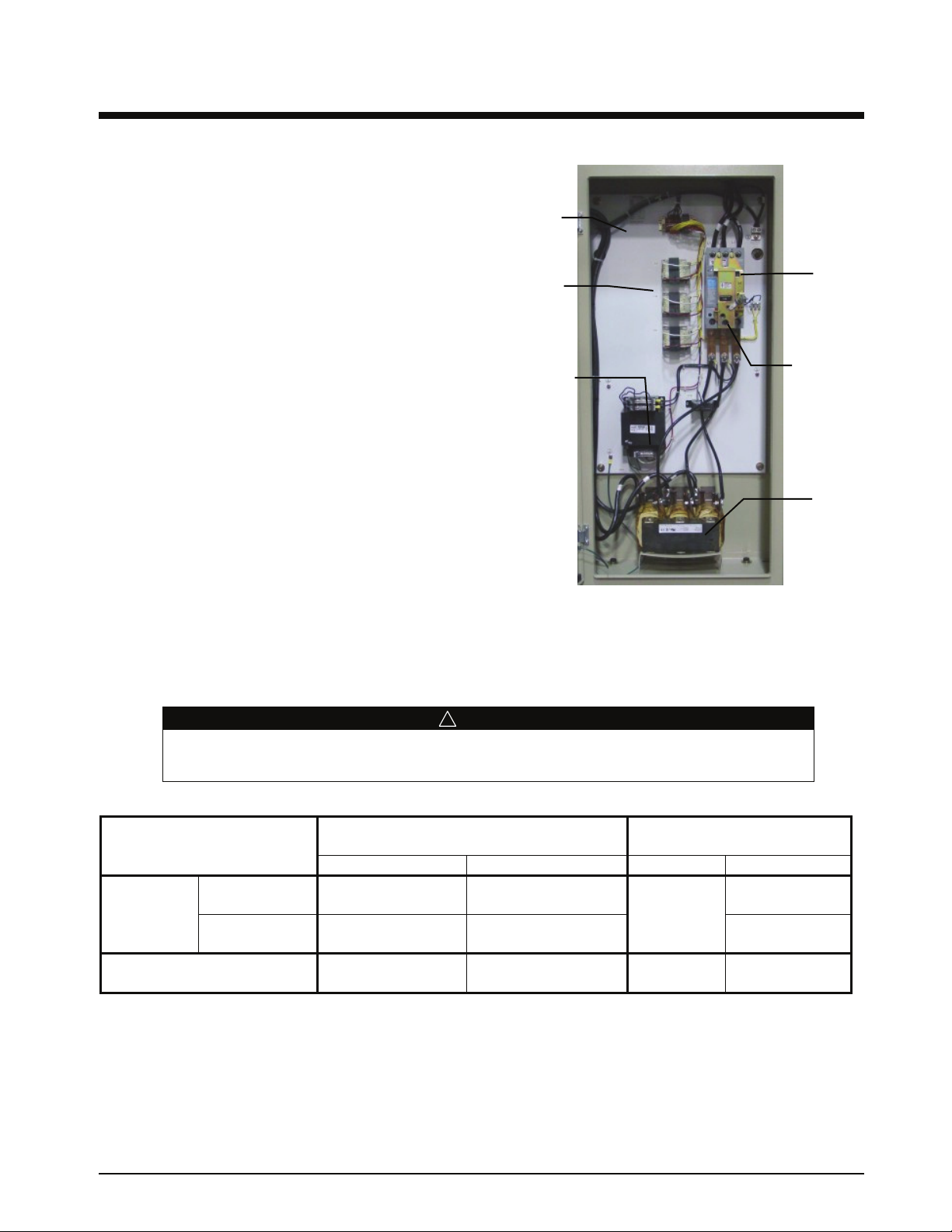
The electrical panel (as shown to the right)
contains the circuit breaker/ disconnect (standard
on both multi-point connection and single-point
connection), a line reactor, and a radio frequency
(RF) filter. The circuit breakers provide
compressor overload protection.
Proper phase sequence to the unit is not required as far as the unit operation is concerned. Correct motor
rotation is established by the chiller control system regardless of the connected phase sequence.
Figure 14, Electrical Panel, Multi-Point Connection
Power
Entry
(3) Controller
Transformers
120V-24V
Control Power
Transformer
480V-120V
Incoming
Lugs
Circuit
Breaker
Line
Reactors
! DANGER
Qualified and licensed electricians must perform wiring. An electrical shock hazard exists that can
cause severe injury or death.
Table 5, WMC Electrical Connections
Power Connection
Power Block Disconnect Power Block Disconnect
Single-point Standard Rated Standard Rated Molded
Single-point Not Available
Multi-point
NOTES
1. Bold type combination is standard offering, all other combinations are options.
2. Circuit breakers have through-the-door disconnect switch handle.
3. When HSCC rating is included, the entire two compressor electric boxes, and single-point box if ordered, are HSCC
rated. HSCCR at 460volts is 65 kA.
Terminal Box Power Block
Each Compressor Standard Rated Standard Rated HSCC Rated
Electric Box Circuit Breaker Circuit Breaker
Not Available
Standard Amp Rating
Case Disc. Switch
(2) Standard Rated
Circuit Breakers
High Short Circuit Current
Rating, HSCC
HSCC Rated
Circuit Breaker
Circuit Breaker
Not Available
(2) HSCC Rated
Circuit Breakers
IMM WMC-2 Centrifugal Chillers 19
Page 20

General Note: The RLA for use in the following tables is obtained by the selection of a specific unit by
McQuay. When shipped, a unit will bear the specific RLA, stamped on the nameplate, for the selected
operating conditions. The tables below are for 60 Hz, 460 volts and 50 Hz, 400 volts.
WMC 145S, Single Compressor
Table 6, Standard Single Point Connection,
1 Compressor Only
(Per Compressor)
79 to 80 Amps 110 97 to 100 3 3 GA 175 Amps
81 to 88 Amps 110 101 to 110 3 2 GA 175 Amps
89 to 92 Amps 110 111 to 115 3 2 GA 200 Amps
93 to 99 Amps 110 116 to 123 3 1 GA 200 Amps
100 Amps 110 125 3 1 GA 225 Amps
101 to 104 Amps 132 126 to 130 3 1 GA 225 Amps
105 to 111 Amps 132 131 to 138 3 1/0 225 Amps
112 to 120 Amps 132 140 to 150 3 1/0 250 Amps
121 to 133 Amps 154 151 to 166 3 2/0 250 Amps
134 to 140 Amps 154 167 to 175 3 2/0 300 Amps
*141 to 150 Amps 165 176 to 187 3 3/0 300 Amps
*50 Hz TT-400 Compressor only
LRA
Minimum Circuit
Ampacity (MCA)
Field Wire RLA
Quantity Wire GA
Max Fuse Size
Table 7, Disconnect Switch Size
RLA
79 to 100 Amps 175 Amps
101 to 150 Amps 225 Amps
NOTE: Disconnect Switch will also be a Circuit Breaker.
Single Point Connection
Disconnect Switch only
WMC 145D, 150D Dual Compressors
Multi-point Connection, Standard
Table 8, WMC 145D, 150D Electrical Data
(Per Compressor)
52 to 55 Amps 72 65 to 69 3 4 GA 110 Amps
56 to 65 Amps 72 70 to 82 3 4 GA 125 Amps
68 to 77 Amps 94 85 to 97 3 3 GA 150 Amps
78 to 85 Amps 94 98 to 107 3 2 GA 175 Amps
89 to 91 Amps 124 112 to 114 3 2 GA 200 Amps
92 to 103 Amps 124 115 to 129 3 1 GA 200 Amps
104 to 110 Amps 124 130 to 138 3 1/0 225 Amps
111 to 113 Amps 124 139 to 142 3 1/0 250 Amps
NOTES
1. Data is for each of two circuits – 1 compressor per circuit
2. See Notes on page 19.
LRA
Minimum Circuit
Ampacity (MCA)
Field Wire RLA
Quantity Wire GA
Max Fuse Size
20 Centrifugal Chillers IMM WMC-2
Page 21

Single-point Connection, Optional
Table 9, WMC 145D, 150D Electrical Data
(Per Compressor)
52 to 53 Amps 72 117 to 120 3 1 GA 150 Amps
54 to 57 Amps 72 122 to 129 3 1 GA 175 Amps
58 to 61 Amps 72 131 to 138 3 1/0 175 Amps
62 to 65 Amps 72 140 to 147 3 1/0 200 Amps
68 to 69 Amps 94 153 to 156 3 2/0 200 Amps
70 to 76 Amps 94 158 to 171 3 2/0 225 Amps
77 to 85 Amps 94 174 to 192 3 3/0 250 Amps
89 to 92 Amps 124 201 to 207 3 4/0 250 Amps
93 to 102 Amps 124 210 to 230 3 4/0 300 Amps
103 to 107 Amps 124 232 to 241 3 250 300 Amps
108 to 113 Amps 124 243 to 255 3 250 350 Amps
NOTE: Total Unit – 2 Compressors per Unit (RLA per Compressor)
LRA
Minimum Circuit
Ampacity (MCA)
Field Wire RLA
Quantity Wire GA
Max Fuse Size
Single Point and Multi-point Connection
Table 10, WMC 145D, 150D Single and Multi-Point Connections
RLA (Per Compressor)
52 to 65 Amps 100 Amps
68 to 85 Amps 150 Amps 335 Amps 400 Amps
89 to 113 Amps 175 Amps
NOTES:
1. Disconnect switch will also be a circuit breaker.
2. A circuit breaker is supplied in each circuit after the power block or molded case disconnect switch.
Disconnect Switch only
Single Point Connection Multi-Point Connection
Power Block Disconnect Switch
WMC250D and 290D Dual Compressor
Multi-Point Connection, Standard
(Per Compressor)
79 to 80 Amps 110 97 to 100 3 3 GA 175 Amps
81 to 88 Amps 110 101 to 110 3 2 GA 175 Amps
89 to 92 Amps 110 111 to 115 3 2 GA 200 Amps
93 to 99 Amps 110 116 to 123 3 1 GA 200 Amps
100 Amps 110 125 3 1 GA 225 Amps
101 to 104 Amps 132 126 to 130 3 1 GA 225 Amps
105 to 111 Amps 132 131 to 138 3 1/0 225 Amps
112 to 120 Amps 132 140 to 150 3 1/0 250 Amps
121 to 133 Amps 154 151 to 166 3 2/0 250 Amps
134 to 140 Amps 154 167 to 175 3 2/0 300 Amps
141 to 150 Amps )Note 1) 165 176 to 187 3 3/0 300 Amps
LRA
Minimum Circuit
Ampacity (MCA)
NOTES:
1. 50 Hz TT-400 Compressor only
2. Each Circuit – 1 Compressor per Circuit
Field Wire RLA
Quantity Wire GA
Max Fuse Size
IMM WMC-2 Centrifugal Chillers 21
Page 22

Single Point Connection, Optional
(Per Compressor)
79 to 88 Amps 110 176 to 199 3 4/0 250 Amps
89 to 92 Amps 110 201 to 208 3 250 MCM 250 Amps
93 to 100 Amps 110 210 to 226 3 250 MCM 300 Amps
101 to 107 Amps 132 228 to 241 3 250 MCM 300 Amps
108 to 113 Amps 132 244 to 255 3 250 MCM 350 Amps
114 to 120 Amps 132 257 to 271 3 300 MCM 350 Amps
121 to 123 Amps 154 273 to 277 3 300 MCM 350 Amps
124 to 126 Amps 154 280 to 284 3 300 MCM 400 Amps
127 to 137 Amps 154 286 to 309 3 350 MCM 400 Amps
138 Amps 154 311 3 400 MCM 400 Amps
139 to 140 Amps 154 313 to 316 3 400 MCM 450 Amps
141 to 148 Amps (Note 1) 165 318 to 334 3 400 MCM 450 Amps
149 to 150 Amps (Note 1) 165 336 to 338 3 500 MCM 450 Amps
LRA
Minimum Circuit
Ampacity (MCA)
NOTES:
1. 50 Hz TT-400 Compressor only
2. Total Unit – 2 Compressors per Unit (RLA Per Compressor)
Table 11, Single Point and Multi-point Connection
RLA
(Per Compressor)
79 to 100 Amps 175 Amps 335 Amps 250 Amps
101 to 150 Amps 225 Amps 380 Amps 400 Amps
NOTES:
1. Disconnect Switch will also be a Circuit Breaker.
2. Circuit Breaker in each circuit after Power Block or Molded Disconnect Switch.
Multi-Point Connection Single Point Connection
Disconnect Switch only Power Block Disconnect Switch
Field Wire RLA
Quantity Wire GA
Max Fuse Size
22 Centrifugal Chillers IMM WMC-2
Page 23
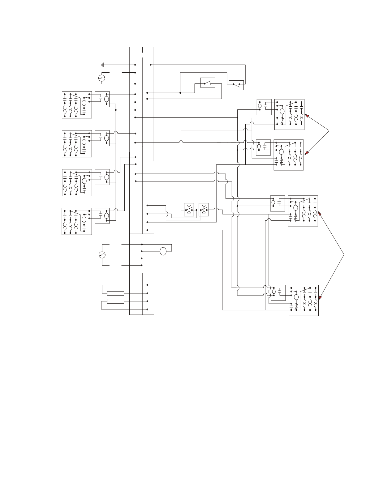
A
CROTECH CO
A
A
A
R
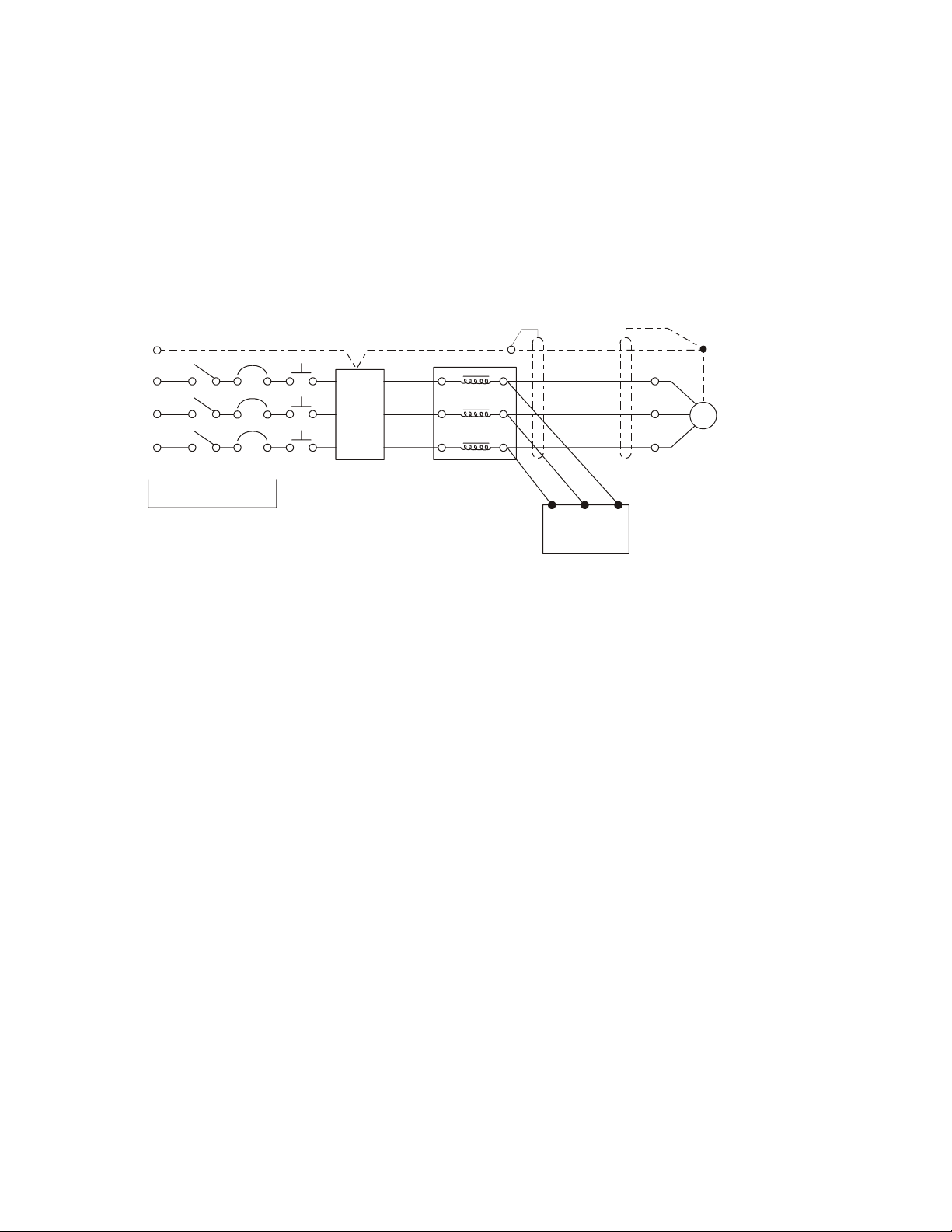
Figure 15, Field Wiring Diagram
O
O
O
O
NOTE 1 0
*
NOTE 1 0
*
*
NOTE 1 0
NOTE 1 0
*
GND
*
C4
C3
C2
C1
* C OOLING
TOWER
FOURTH
STAGE
STARTER
H
A
* C OOLING
TOWER
THI RD
STAGE
STARTER
H
A
* C OOLING
TOWER
SECOND
STAGE
STARTER
* C OOLING
TOWER
FIRST
STAGE
STARTER
H
A
H
A
PO WER
NOTE 7
NEUTRA L
COMMON
*
NOTE 4
PO WER
MI
BO X TERMIN ALS
(115V) (24V)
UTB1
PE
85
86
80
74
86
86
79
73
78
77
76
75
81
82(NO)
83(NC)
84
70
55
CF1
EF1
EF2
CF2
NTROL
54
A
(NOTE 6 )
SWI TCH
DELTA P
FLOW O R
EVAP.
* AL ARM RELAY
(NOTE 4 )
*
MODE SWITCH
(NOTE 6 )
SWI TCH
DELTA P
FLOW OR
COND.
* REMOTE
ON/OFF
(NOTE 5 )
*NOTE 8
EP2
NOTE 1 1
*
NOTE 8
EP1
NOTE 1 1
*
NOTE 9
NOTE 11
O
O
EWI- 1
H
EWI- 2
H
CP2
C
* CHILLED
WATER
PUMP
STARTERS
C
H
O
C
CWI-2
* CONDENSE
WATER
PUMP
STARTERS
*C OOLING TOWER BYPASS VALUE
*C OOLING TOWER VFD
0-10 VDC
0-10 VDC
52
71
71
53
NOTE 9
*
NOTE 11
CP1
H
O
C
CWI-1
Field Wiring Diagram Notes
1. Compressor terminal boxes are factory-mounted and wired. All line-side wiring must be in accordance with the NEC and be made
with copper wire and copper lugs only. Power wiring between the terminal box and compressor terminals is factory installed.
2. Minimum wire size for 115 VAC is 12 ga. for a maximum length of 50 feet. If greater than 50 feet refer to McQuay for
recommended wire size minimum. Wire size for 24 VAC is 18 ga. All wiring to be installed as NEC Class 1 wiring system. All
24 VAC wiring must be run in separate conduit from 115 VAC wiring. Wiring must be wired in accordance with NEC and
connection to be made with copper wire and copper lugs only.
3. Voltage unbalance not to exceed 2% with a resultant current unbalance of 6 to 10 times the voltage unbalance per NEMA MG-1,
1998 Standard.
4. A customer furnished 24 or 120 vac power for alarm relay coil may be connected between UTB1 terminals 84 power and 81
neutral of the control panel. For normally open contacts wire between 82 & 81. For normally closed wire between 83 & 81. The
alarm is operator programmable. Maximum rating of the alarm relay coil is 25VA.
5. Remote on/off control of unit can be accomplished by installing a set of dry contacts between terminals 70 and 54.
6. If field supplied pressure differential switches are used, they must be installed across the vessel and not the pump. They must be
suitable for 24 vac and low current application.
7. Customer supplied 115 VAC 20 amp power for optional evaporator and condenser water pump control power and tower fans is
supplied to unit control terminals (UTB1) 85 power / 86 neutral, PE equipment ground.
Page 24

8. Optional customer supplied 115 VAC, 25-VA maximum coil rated, chilled water pump relay (ep1 & 2) may be wired as shown.
This option will cycle the chilled water pump in response to chiller demand.
9. The condenser water pump must cycle with the unit. A customer supplied 115 VAC 25 VA maximum coil rated, condenser water
pump relay (CP1 & 2) is to be wired as shown. Units with free-cooling must have condenser water above 60°F before starting.
10. Optional customer supplied 115 VAC 25 VA maximum coil rated cooling tower fan relays (C1 - C2 standard, C3-C4 optional)
may be wired as shown. This option will cycle the cooling tower fans in order to maintain unit head pressure.
11. Auxiliary 24 VAC rated contacts in both the chilled water and condenser water pump starters must be wired as shown.
12. 4-20mA external signal for chilled water reset are wired to terminals 71 and 51 on the unit controller; load limit is wired to
terminals 71 and 58 on the unit controller.
13. Optional Control Inputs. The following 4-20 ma optional inputs are connected as shown:
• Demand Limit; Terminals 58 and 71 common
• Chilled Water Reset; Terminals 51 and 71 common
• Evaporator Water Flow; Terminals 59 and 71 common
• Condenser Water Flow; Terminals 60 and 71 common
14. Optional Control Power Source. 115 volt control power can be supplied from a separate circuit and fused at 20 amps inductive
load. Connection is to terminals 85 and 86 common.
15. 4-20 mA external signal for chilled water reset are wired to terminals 71 and 51 on the unit controller; load limit is wired to
terminals 71 and 58 on the unit controller.
Care must be taken when attaching leads to compressor terminals to assure proper sequencing and connection
torque.
Control Wiring
The control circuit on the McQuay centrifugal packaged chiller is designed for 115-volts. Control power is
supplied from a factory-wired transformer located in the electrical box.
Use with On-Site Generators
WMC chillers have their total tonnage divided between two compressors that start sequentially and they are
operated with variable frequency drives. These features make WMC chillers especially appropriate for use in
applications where they may be required to run with on-site electrical generators. This is particularly true when
the generators are used for temporary power when the utility power is lost.
Generator Sizing: Gas and diesel generators are sensitive to the compressor’s locked-rotor characteristics when
the chillers start up. Use the electrical data supplied with the performance output sheet, obtained from the
McQuay sales office, for generator sizing purposes. The chiller data sheet will show the RLA, which is for both
compressors. Refer to the electrical data on page 19 to determine the LRA, based on the RLA. It is important to
size the generator to handle the LRA at start up.
Starting/Stopping Procedure: The stopping of the chiller in the event of a power failure should be uneventful.
The chiller will sense a loss of voltage and the compressors will stop, coasting down using power generated from
their dynamic braking to maintain the bearing magnetic field. The stop signal will initiate a three-minute stop-tostart timer, effectively preventing compressor restart for three minutes. The timer is adjustable from three to
fifteen minutes, but the recommended default value is three minutes. This interval allows the generator sufficient
time to get up to speed and stabilize. The chiller will restart automatically when the start-to-start timer expires.
Transfer Back to Grid Power: Proper transfer from stand-by generator power back to grid power is essential to
avoid compressor damage.
! WARNING!
Stop the chiller before transferring supply power from the generator back to the utility power grid.
Transferring power while the chiller is running can cause severe compressor damage..
The necessary procedure for reconnecting power from the generator back to the utility grid is show below. These
procedures are not peculiar to McQuay units only, but should be observed for any chiller manufacturer.
24 Centrifugal Chillers IMM WMC-2
Page 25

1. Set the generator to always run five minutes longer than the unit start-to-start timer, which could be set from
15 to 60 minutes. The actual setting can be viewed on the operator interface panel on the Setpoint/Timer
screen.
2. Configure the transfer switch, provided with the generator, to automatically shut down the chiller before
transfer is made. This function can be accomplished through a BAS interface or with the “remote on/off”
wiring connection shown in
three-minute start-to-start timer will be in effect.
Chiller Control Power: For proper operation on standby power, the chiller control power must remain as
factory-wired from a unit-mounted transformer. Do not supply chiller control power from an external power
source because the chiller may not sense a loss of power and do a normal shutdown sequence.
Figure 15. A start signal can be given anytime after the stop signal since the
System Pumps
Operation of the chilled water pump can be to 1) cycle the pump with the compressor, 2) operate continuously, or
3) start automatically by a remote source.
The cooling tower pump must cycle with the machine. The holding coil of the cooling tower pump motor starter
must be rated at 115 volts, 60 Hz, with a maximum volt-amperage rating of 100. A control relay is required if the
voltage-amperage rating is exceeded. See the Field Wiring Diagram on page 23 or in the cover of control panel
for proper connections.
All interlock contacts must be rated for no less than 10 inductive amps. The alarm circuit provided in the control
center utilizes 115-volts AC. The alarms must not draw more than 10-volt amperes.
VFD Line Harmonics
Despite their many benefits, care must be taken when applying VFDs due to the effect of line harmonics on the
building electric system. VFDs cause distortion of the AC line because they are nonlinear loads, that is, they
don't draw sinusoidal current from the line. They draw their current from only the peaks of the AC line, thereby
flattening the top of the voltage waveform. Some other nonlinear loads are electronic ballasts and uninterruptible
power supplies.
Line harmonics and their associated distortion can be critical to ac-drives for three reasons:
1. Current harmonics can cause additional heating to transformers, conductors, and switchgear.
2. Voltage harmonics upset the smooth voltage sinusoidal waveform.
3. High-frequency components of voltage distortion can interfere with signals transmitted on the AC
line for some control systems.
th
The harmonics of concern are the 5
magnitude harmonics are usually not a problem.
Current Harmonics
An increase in reactive impedance in front of the VFD helps reduce the harmonic currents. Reactive impedance
can be added in the following ways:
1. Mount the drive far from the source transformer.
2. Add line reactors. They are standard equipment on WMC chillers.
3. Use an isolation transformer.
4. Use a harmonic filter.
, 7th, 11th, and 13th. Even harmonics, harmonics divisible by three, and high
Voltage Harmonics
Voltage distortion is caused by the flow of harmonic currents through a source impedance. A reduction in source
impedance to the point of common coupling (PCC) will result in a reduction in voltage harmonics. This can be
done in the following ways:
Page 26

1. Keep the PCC as far from the drives (close to the power source) as possible.
2. Increase the size (decrease the impedance) of the source transformer.
3. Increase the capacity (decrease the impedance) of the busway or cables from the source to the PCC.
4. Make sure that added reactance is "downstream" (closer to the VFD than the source) from the PCC.
Line Reactors
Five-percent line reactors are standard equipment on WMC chillers and located in each compressors power
panel. They are employed to improve the power factor by reducing the effects of harmonics.
Harmonic Filter
The harmonic filter is an option for field mounting and wiring outside of the power panel. It works in
conjunction with the line reactor to further minimize harmonic distortion. It is wired between the line reactor and
compressor. IEEE 519-1991 Standard defines acceptable limits.
See the WMC certified drawings for harmonic filter dimensions and wiring information.
EMI (Electro Magnetic Interference) and RFI (Radio Frequency Interference) Filter
This filter is a factory-installed option. The terms EMI and RFI are often used interchangeably. EMI is actually
any frequency of electrical noise, whereas RFI is a specific subset of electrical noise on the EMI spectrum. There
are two types of EMI. Conducted EMI is unwanted high frequencies that ride on the AC wave form.
EMI
Radiated EMI is similar to an unwanted radio broadcast being emitted from the power lines. There are many
pieces of equipment that can generate EMI, variable frequency drives included. In the case of variable frequency
drives, the electrical noise produced is primarily contained in the switching edges of the pulse width modulation
(PWM) controller.
As the technology of drives evolves, switching frequencies increase. These increases also increase the effective
edge frequencies produced, thereby increasing the amount of electrical noise.
The power line noise emissions associated with variable frequency and variable speed drives can cause
disturbances in nearby equipment. Typical disturbances include:
• Dimmer and ballast instability
• Lighting disturbances such as flashing
• Poor radio reception
• Poor television reception
• Instability of control systems
• Flow meter totalizing
• Flow metering fluctuation
• Computer system failures including the loss of data
• Thermostat control problems
• Radar disruption
• Sonar disruption
RFI
Three-phase filters are supplied as an option for factory mounting in the compressor power panels. They use a
combination of high frequency inductors and capacitors to reduce noise in the critical 150 kHz to 30 MHz
frequency range. The inductors act as open circuits and the capacitors act as short circuits at high frequencies
while allowing the lower power line frequencies to pass untouched. The filters assist with cost effective
compliance to Electro Magnetic Compatibility (EMC) directives, in a compact, efficient, light-weight design.
The high common mode and differential mode reduction in the critical 150kHz to 30MHz frequencies assures
that potential interference from AC drives is reduced or eliminated.
26 Centrifugal Chillers IMM WMC-2
Page 27
The filters are current-rated devices. In order to properly size a filter, it is necessary to know the operating
voltage and the input current rating of the drive. No derating or re-rating is necessary when applying the filter at
voltages that are less than or equal to the maximum voltage listed on the filter.
The IEEE 519-1991 Standard
The Institute of Electrical and Electronics Engineers (IEEE) has developed a standard that defines acceptable
limits of system current and voltage distortion. A simple form is available from McQuay that allows McQuay to
determine compliance with IEEE 519-1991.
Line reactors, isolation transformers, or phase-shifting transformers can be required on some installations.
Figure 16, Typical WMC Power Wiring
WMC Wiring
GND
Contactor
Optional
EMI
Filter
(1)
C
AC Input
Voltage
L1
L2
L3
Manual
Disconnect
Optional
Notes:
(1) Single hole, crimp type compression terminal required.
(2) Connect to filter circuit breaker lugs.
(3) Conductors to be sized for 125 minimum circuit ampacity.
Size 1 AWG, 75°C wire recommended.
Standard
Line
Reactor
(3)
(2) Hamonic
Filter with
Circuit Breaker
Page 28

Multiple Chiller Setup
WMC dual compressor units have their main control components factory wired to an internal network so that
the components can communicate with each other, within the chiller itself.
On multi-chiller WMC applications, two WMC chillers can be interconnected by simple field RS485
interconnecting wiring, the addition of an accessory communication isolation board(s) 485OPDR (McQuay P/N
330276202), and some MicroTech II control settings. The 485OPDR isolation board can be purchased with the
unit or separately, during or after chiller installation. Only one board is required required. WMC chillers cannot
be interconnected with WSC, WDC, or WCC chillers.
Communication Setup
Interconnecting MicroTech II pLAN RS485 wiring should be installed by the installing contractor prior to startup. The McQuay start-up technician will check the connections and make the necessary set point settings.
1. With no pLAN connections between chillers, disconnect chiller control power and set the DIP switches as
shown in Table 12.
2. With all manual switches off, turn on control power to each chiller and set each OITS address (see Note 2 on
page 28).
3. Verify correct nodes on each OITS Service Screen.
4. Connect chillers together (RS485 wiring) as shown in Figure 16. The first chiller in the connection can be
designated as Chiller A. The isolation board is attached to the DIN rail adjacent to the Chiller A unit
controller. The isolation board has a pigtail that is plugged into J10 on the controller. Most chillers will
already have a universal communication module (UCM) that connects the controller to the touchscreen
already plugged onto J10. If this is the case, plug the isolation module pigtail into the empty RJ11 pLAN
port on the UCM. This is equivalent to plugging into the unit controller directly.
Next, interconnecting wiring is needed between Chiller A and Chiller B.
Interconnection: Belden M9841 (RS 485 Spec Cable) is wired from the 485OPDR isolation board
(terminals A, B, and C) on Chiller A to the J11 port on the unit controller of Chiller B. At J11, the shield
connects to GND, the blue/white wire to the (+) connection, and the white/blue to the (-) connection.
Note that Chiller B does not have, or need, an isolation board.
5. Verify correct nodes on each OITS Service Screen.
Table 12, Address DIP Switch Settings for Controllers Using pLAN.
Chiller Comp 1 Comp 2 Unit
(1) Controller Controller Controller
A
B
NOTES:
1. Up to four single or dual compressors can be interconnected.
2. The Operator Interface Touch Screen (OITS) setting is not a DIP switch setting. The OITS address is selected by
selecting the ‘service’ set screen. Then, with the Technician level password active, select the ‘pLAN Comm’ button.
Buttons A(7), B(15), C(23), D(31) will appear in the middle of the screen, then select the letter for the OITS address for
the chiller that it is on. Then close the screen. Note that A is the default setting from the factory.
3. Six Binary Switches: Up is ‘On’, indicated by ‘1’. Down is ‘Off’, indicated by ‘0’
28 Centrifugal Chillers IMM WMC-2
1 2 5 6 7 8
100000 010000 101000 011000 111000 000100
9 10 13 14 15 16
100100 010100 101100 011100 111100 000010
Reserved
Operator
Interface (2)
.
Reserved
Page 29
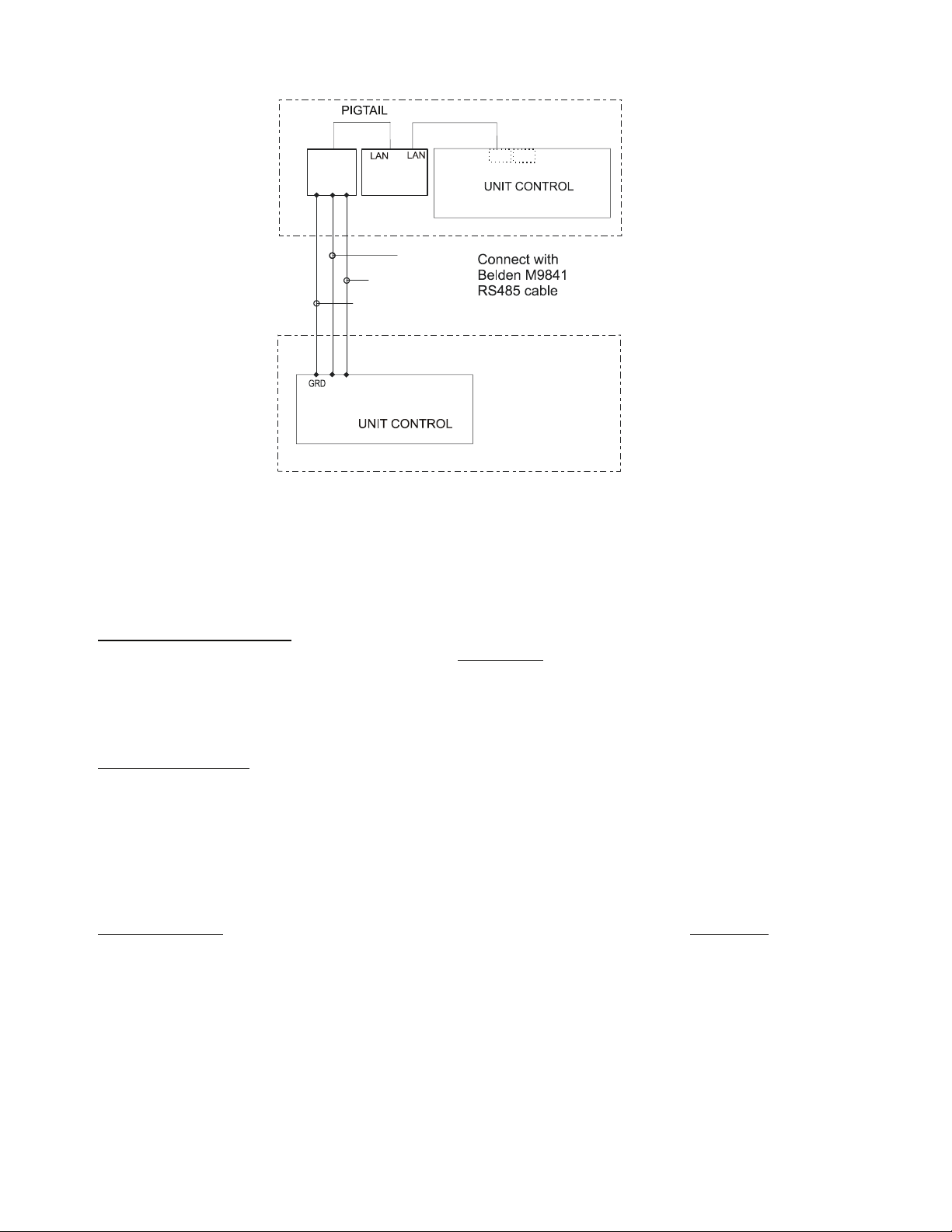
Figure 17, Communication Wiring
A
Chiller
J10
485
OPDR
C
P
P
B
UCM
A
BLU/WHT
WHT/BLU
SHIELD
J11
Chiller B
(-)
(+)
PORT
J11
MicroTech II Operator Interface Touch Screen (OITS) Settings
Settings for any type of linked multiple compressor operation must be made to the MicroTech II controller.
Settings on a dual compressor unit are made in the factory prior to shipment, but must be verified in the field
before startup. Settings for multiple chiller installations are set in the field on the Operator Interface Touch
Screen as follows:
Maximum Compressors ON – SETPOINTS - MODES screen, Selection #10 ‘= 2 for a dual, 4 for 2 duals, 3 for
three separate, single compressor chillers, etc. If all
compressors in the system are to be available as normal
running compressors, then the value entered in #10 should equal the total number of compressors. If any
compressors are for standby and not operated in normal rotation, they should not be included in the compressor
count in Selection #10. The Max Comp ON setting can be made in only one touchscreen, the system will
observe the highest number set on all chillers-it is a global setting.
Sequence and Staging – SETPOINTS - MODES screen, Selection #12 & #14; #11 & #13. Sequence sets the
sequence in which compressors will start. Setting one or more compressors to “1” evokes the automatic lead/lag
feature and is the normal setting. The compressor with least starts will start first and the compressor with
maximum hours will stop first, and so on. Units with higher numbers will stage on in sequence.
The Modes setpoints will do several different types of operation (Normal, Efficiency, Standby, etc.) as described
in the operating manual.
The same Modes setting must be replicated on each chiller in the system.
Nominal Capacity – SETPOINTS - MOTOR screen, Selection #14. The setting is the compressor design tons.
Compressors on dual units are always of equal capacity.
Page 30

Operating Sequence
For multiple-chiller, parallel operation, the MicroTech II controllers are tied together by a communications
network and stage and control compressor loading among the chillers. Each compressor, single or dual
compressor chiller, will stage on or off depending on the sequence number programmed into it. For example, if
all are set to “1”, the automatic lead/lag will be in effect.
When chiller #1 is fully loaded, the leaving chilled water temperature will rise slightly. When the Delta-T above
setpoint reaches the Staging Delta-T, the next chiller scheduled to start will receive a start signal and start its
pumps if they are set up to be controlled by the MicroTech II® controller. This procedure is repeated until all
chillers are running. The compressors will load-balance themselves.
If any of the chillers in the group are dual compressor, they will stage and load according to the staging
instructions.
See OM WMC (current edition) for a complete description of the various staging sequences available.
Prestart System Checklist
Yes No N/A
Chilled Water
Piping complete .......................................................................................
Water system filled, vented......................................................................
Pumps installed, (rotation checked), strainers cleaned ............................
Controls (3-way, face and bypass dampers, bypass valves, etc.) operable
Water system operated and flow balanced to meet unit design requirements
Condenser Water
Cooling tower flushed, filled and vented ................................................
Pumps installed, (rotation checked), strainers cleaned ...........................
Controls (3-way, bypass valves, etc.) operable .......................................
Water system operated and flow-balanced to meet unit requirements ....
Electrical
Power leads connected to the unit power panel(s) ..................................
All interlock wiring complete between control panel and complies with specifications
Pump starters and interlock wired ...........................................................
Cooling tower fans and controls wired ...................................................
Wiring complies with National Electrical Code and local codes ............
Condenser pump starting relay (CWR) installed and wired ...................
Miscellaneous
Relief valve piping complete ..................................................................
Thermometer wells, thermometers, gauges, control wells, controls, etc., installed
Minimum system load of 80% of machine capacity available for testing
and adjusting controls .............................................................................
Control wiring between multiple units, if applicable.........................................................
Note: This checklist must be completed and sent to the local McQuay Factory Service location two weeks prior
to start-up.
30 Centrifugal Chillers IMM WMC-2
Page 31

Operation
Operator Responsibilities
It is important that the operator become familiar with the equipment and the system before attempting to operate
the chiller.
During the initial startup of the chiller, the McQuay technician will be available to answer any questions and
instruct in the proper operating procedures.
It is recommended that the operator maintain an operating log for each individual chiller unit. In addition, a
separate maintenance log should be kept of the periodic maintenance and servicing activities.
Now that you have made an investment in modern, efficient McQuay equipment, its care and operation should be
a high priority. For training information on all McQuay HVAC products, please visit us at www.mcquay.com and
click on Training, or phone 540-248-0711 and ask for the Training Department. These sessions are structured to
provide basic classroom instruction and include hands-on operating and troubleshooting exercises.
Compressor Operation
The WMC compressors are two-stage. Suction gas enters the compressor through inlet guide vanes that can be
opened and closed to control refrigerant flow as the cooling load changes. The suction gas enters the first stage
impeller, is compressed, and travels through the vaned radial diffuser to the second stage impeller where
compression is completed. The gas travels to the condenser via the discharge volute, which converts any
remaining velocity pressure to static pressure.
Motor cooling is accomplished by utilizing the refrigerant effect of high-pressure liquid refrigerant from the
condenser expanded to a gas within the compressor. The refrigerant cools VFD heat sinks and the motor.
A five-axis magnetic bearing system supports the motor/compressor shaft, resisting radial and thrust forces. The
bearing control system uses shaft position feedback to continually adjust the bearing to keep the shaft in the
correct position. In the event of a power failure, the compressor motor acts as a generator and powers the bearing
support system during coastdown. There is also a system to gently de-levitate the shaft.
Many controls are mounted directly on the compressor where they monitor and control compressor operation.
These compressor controls are interfaced with the conventional MicroTech II controls to provide a complete
chiller control system.
Operating Limits:
Maximum standby ambient temperature, 130°F (55°C)
Minimum operating ambient temperature (standard), 35°F (2°C)
Leaving chilled water range, 38°F to 60°F (3°C to 15°C)
Maximum operating evaporator inlet fluid temperature, 66°F (19°C)
Maximum startup evaporator inlet fluid temperature, 90°F (32°C)
Maximum non-operating inlet fluid temperature, 100°F (38°C)
Minimum condenser water entering temperature (with condenser bypass), 55°F (12.8°C)
Maximum entering condenser water temperature, 105°F (40.6°C)
Maximum leaving condenser water temperature, 115°F (46.1°C)
Page 32

System Water Volume
It is important to have adequate water volume in the system to provide an opportunity for the chiller to sense a
load change, adjust to the change, and stabilize. As the expected load change becomes more rapid, a greater
water volume is needed. The system water volume is the total amount of water in the evaporator, air handling
products and associated piping. If the water volume is too low, operational problems can occur including rapid
compressor cycling, rapid loading and unloading of compressors, erratic refrigerant flow in the chiller, improper
motor cooling, shortened equipment life and other undesirable consequences.
Some of the things the designer should consider when looking at water volume are the minimum cooling load,
the minimum chiller plant capacity during the low load period and the desired cycle time for the compressors.
Assuming that there are no sudden load changes and that the chiller plant has reasonable turndown, a rule of
thumb of “gallons of water volume equal to two to three times the chilled water gpm flow rate” is often used.
For process applications where the cooling load can change rapidly, additional system water volume is needed. A
process example would be a quenching tank. The load would be very stable until the hot material is immersed in
the water tank. Then, the load would increase drastically. For this type of application, system volume may need
to be increased.
Since there are many other factors that can influence performance, systems may successfully operate below these
suggestions. However, as the water volume decreases below these suggestions, the possibility of problems
increases.
Variable Speed Pumping
Variable water flow involves inversely changing the water flow through the evaporator as the load changes.
McQuay chillers are designed for this duty provided that the rate of change in water flow is slow and the
minimum and maximum flow rates for the vessel, as shown in Figure 11 on page 16 are not exceeded.
The recommended maximum change in water flow is 10 percent of the allowable flow change per minute. Flow
is usually not reduced below 50 percent of design flow (provided vessel minimum flow rates are not exceeded).
For example, a 150-ton chiller might have chilled water flow of 360 gpm, reduced to 50 percent, would be 180
gpm. However, the minimum flow rate is 216 gpm, so the flow change would be 360 gpm minus 216 gpm, or
144 gpm. This means that the allowable flow rate change would be 10 percent of 144 or 14.4 gpm per minute.
MicroTech II Control
Figure 18, MicroTech II Control Panel
• Operator interface touchscreen panel (shown at the left). It
• Control Panel containing the MicroTech II
WMC chillers are equipped with the McQuay MicroTech II
control system consisting of:
contains a 15-inch Super VGA color screen.
unit controller, two
MicroTech II
compressor-mounted controls, and various switches and field
connection terminals.
Operating instructions for the MicroTech II controller are
contained in Operating Manual OM WMC-3.
compressor controllers with connections to the
32 Centrifugal Chillers IMM WMC-2
Page 33

Building Automation Systems
All MicroTech II controllers with Open Choices™ are capable of BAS communications, providing easy
integration and comprehensive monitoring, control, and two-way data exchange with open standard protocols
such as L
Open Choices™ Benefits
Easy to integrate into your building automation system of choice
••
Factory-installed and tested communication module
••
Comprehensive point list for system integration, equipment monitoring and alarm notification
••
Provides efficient equipment operation
••
Owner/designer can select the BAS that best meets building requirements
••
Comprehensive data exchange
••
Integration Made Easy
McQuay unit controllers strictly conform to the interoperability guidelines of the LONMARK ® Interoperability
Association and BACnet International. They have received L
communication module.
Protocol Options
The BAS communication module can be ordered with a chiller and factory-mounted or can be field-mounted at
any time after the chiller unit is installed.
onTalk®, Modbus® or BACnet®.
BACnet MS/TP
•
•
BACnet IP
•
•
BACnet Ethernet
•
•
L
ONWORKS® (FTT-10A)
•
•
Modbus RTU
•
•
ONMARK certification with optional LONWORKS
Table 13, Typical Data Point Availability
Typical Data Points
Active Setpoint R Cond EWT R Evap Water Pump Status R
Actual Capacity R Cond Flow Switch Status R Liquid Line Refrigerant Pressure R
Capacity Limit Output R Cond LWT R Liquid Line Refrigerant Temp R
Capacity Limit Setpoint W Cond Pump Run Hours R Maximum Send Time W
Chiller Enable W Cond Refrigerant Pressure R Minimum Send Time W
Chiller Limited R
Chiller Local/Remote R Cond Water Pump Status R Pump Select W
Chiller Mode Output R Cool Setpoint W Run Enabled R
Chiller Mode Setpoint W Current Alarm R
Chiller On/Off R Default Values W
Chiller Status R Evap EWT R
Compressor Discharge Temp R Evap Flow Switch Status R
Compressor Percent RLA R Evap LWT for Unit R
Compressor Run Hours R Evap LWT for Compressor R
Compressor Select W Evap Pump Run Hours R
Compressor Starts R Evap Refrigerant Pressure R
Compressor Suction Line
Temp
Note: Data points available are dependent upon options selected.
Cond Sat. Refrigerant
Temp
Evap Sat. Refrigerant
R
Temp
1
(W = Write, R = Read)
R Network Clear Alarm W
R
Connection to Chiller
Connection to the chiller for all BAS protocols will be at the unit controller. An interface card, depending on the
protocol being used, will have been factory installed in the unit controller if so ordered, or it can be field
installed.
Page 34

Protocols Supported
Table 14, Standard Protocol Data
Protocol Physical Layer Data Rate Controller Other
BACnet®/IP
BACnet MSTP RS485 (TBD)
LonTalk®
Modbus RTU RS-485 (TBD)
NOTE: For additional information on the protocol data available through the BACnet or LonTalk
communications modules, reference McQuay ED 15062, MicroTech II Chiller Unit Controller Protocol
Information.
Modbus - When selected, the ident number and baud can also be changed to suit the application.
ONWORKS – When selected, the ident number and baud rate setpoints are not available. Baud rate is locked at
L
4800.
BACnet – When selected, the ident number and baud rate setpoints are not available. Baud rate is locked at
19200.
The factory installed communication module kits on the MicroTech II™ controller are as follows:
• BACnet Kit P/N 350147404: BACnet/IP, BACnet MS/TP, or BACnet Ethernet
ONWORKS Kit P/N 350147401: LonTalk (FTT-10A)
• L
• Modbus RTU
If an interface module was ordered, one of the following BAS interface installation manuals was shipped with the
unit. If necessary, contact your local McQuay sales office for a replacement or obtain from www.mcquay.com.
Ethernet 10 Base-T 10 Megabits/sec Color graphics SBC Reference ED 15057: BACnet PICS
FTT-10A 78kbits/sec
2
pCO
Unit Controller
2
pCO
Unit Controller
2
pCO
Unit Controller
Reference ED 15057: BACnet PICS
LONMARK® Chiller Functional
Profile
• IM 735, L
ONWORKS® Communication Module Installation
• IM 736, BACnet® Communication Module Installation
• IM 743, Modbus® Communication Module Installation
34 Centrifugal Chillers IMM WMC-2
Page 35

SW1, Unit Switch
SW12, Circ #1 Switch
SW22, Circ #2 Switch
Control Circuit Breaker
Figure 19, Unit Control Panel
Unit Terminal Board
Unit Controller
Circuit # 1 Controller
Circuit #1 Terminal
Board, TB1
Circuit # 2 Controller
Circuit #2 Terminal
Board, TB2
MOD1, MOD2 Ground
Capacity Control System
The capacity of the chiller is controlled by:
1) Staging the compressors on and off;
2) By adjusting the capacity of each compressor by opening or closing the inlet vanes to control the
quantity of refrigerant entering the impeller; and,
3) Varying compressor speed to change capacity.
Page 36

The speed control and vane control work in conjunction. As load decreases, compressor speed is reduced as low
as possible but above the point where stall might begin. If further capacity reduction is required, the guide vanes
will close to whatever position is required to match the compressor capacity to the load.
Surge and Stall
Stall and surge are a characteristic of all centrifugal compressors. These conditions can occur at low load
conditions when the operating point moves to the left of the compressor surge line on the performance curve.
In surge, the discharge gas alternately flows backward and forward through the impeller reversing about every
two seconds. Increased noise, vibration and heat occur and motor current varies widely. Surge can damage a
compressor. The compressors are equipped with safety features that help prevent surge from occurring.
Another instability is stall or incipient surge, which occurs a little to the left, or before, the surge condition.
Discharge gas in the diffuser forms rotating stall pockets or cells. The compressor sound level will change and
the impeller starts to heat up. Motor current remains steady.
Normal Unit Startup/Shutdown
Startup and shutdown, other than seasonal shutdowns, are considered to be normal operation and the following
procedures apply (assuming that the equipment room temperature are above freezing). The procedures would be
used for a weekend shutdown, for example.
Note that the chiller is part of an entire building heating and cooling system that are usually unique to a particular
site. For example, the chilled water loop and chilled water pump can also be used for heating and therefore must
be operational year-around. The cooling tower can be used for other equipment besides the chiller and may have
to remain functional even though the chiller is not. The following procedures, therefore, must take the
peculiarities of the entire system into account.
Shutdown
If the unit is to be secured for several days, and is already off due to lack of load, the UNIT switch in the Unit
Control Panel (and the remote Start/Stop switch, if used) should be placed in the OFF position. If the chilled
water pump and cooling tower are not required for other purposes, they too can be turned off. If the pumps are
controlled by the WMC unit controller, they will shut down after the compressors.
If the chiller is running, the chilled water and condenser water pumps must remain on until the compressors are
stopped. This is true regardless of how the unit is turned off, whether by the local switches or through a remote
signal. The compressors go through a short shutdown sequence, shutting guide vanes and performing other
functions, before it finally stops. The pumps must remain on during this shutdown period.
Once the compressors and pumps have stopped, no further action is required other than opening disconnects, if
so desired.
Startup
Any disconnects that were opened must be closed. The chilled water pump and cooling tower should be turned
on and flow verified. The chiller can then be started by placing the UNIT switch (and the remote Start/Stop
switch, if used) in the ON position. There is no lube warm-up period required. The compressors go through a
starting sequence and may not start immediately. Once started, it is prudent to observe unit operation on the
operator interface screen for several minutes to check for normal functioning.
Start/Stop Switching
There are four ways to start/stop the chiller. Three are selected in SETPOINT\ MODE\SP3, the fourth way is
through panel-mounted switches:
1. Operator Interface Panel, (LOCAL) Home Screen 1 has AUTO and STOP buttons that are only active
when the unit is in "LOCAL CONTROL". This prevents the unit from being accidentally started or stopped
36 Centrifugal Chillers IMM WMC-2
Page 37

when it is under control from a remote switch or BAS. When these buttons are pressed, the unit will cycle
through its normal starting or stopping sequence, both compressors will be stopped and normal dual
compressor starting procedure will be in effect.
2. Remote SWITCH, Selecting SWITCH in SP3 will put the unit under the control of a remote switch that
must be wired into the control. See Field Wiring Diagram, page 23.
3. BAS, BAS input is field-wired into a communication module that is factory-installed on the unit controller.
4. Control Panel Switches
Three On/Off switches are located in the upper left corner of the main Control Panel, which is adjacent to the
operator interface panel, and have the following function:
•
UNIT shuts down the chiller through the normal shutdown cycle of unloading the compressors.
•
COMPRESSOR one switch for each compressor on the unit, executes an immediate shutdown without
the normal shutdown cycle.
• CIRCUIT BREAKER disconnects optional external power to system pumps and tower fans.
A fourth switch located on the left outside of the Unit Control Panel and labeled
SWITCH stops the compressor immediately. It is wired in series with the COMPRESSOR On/Off switches.
EMERGENCY STOP
Annual Unit Startup/Shutdown
Annual Shutdown
Where the chiller can be subject to freezing temperatures, the condenser and chiller must be drained of all water.
Dry air blown through the condenser will aid in forcing all water out. Removal of condenser heads is also
recommended. The condenser and evaporator are not self-draining and tubes must be blown out. Water
permitted to remain in the piping and vessels can rupture these parts if subjected to freezing temperature.
Forced circulation of antifreeze through the water circuits is one method of avoiding freeze up.
1. Take measures to prevent the shutoff valve in the water supply line from being accidentally turned on.
2. If a cooling tower is used and if the water pump will be exposed to freezing temperatures, be sure to remove
the pump drain plug and leave it out so any water that can accumulate will drain away.
3. Open the compressor disconnect switch. Set the manual COMPRESSOR and UNIT ON/OFF switches in
the Unit Control Panel to the OFF position.
4. Check for corrosion and clean and paint rusted surfaces.
5. Clean and flush water tower for all units operating on a water tower.
6. Remove condenser heads at least once a year to inspect the condenser tubes and clean if required.
Annual Startup
1. Check and tighten all electrical connections.
2. Replace the drain plug in the cooling tower pump if it was removed at shutdown time the previous season.
3. Install fuses in main disconnect switch (if removed).
4. Reconnect water lines and turn on supply water. Flush condenser and check for leaks.
Page 38
Maintenance
Wait 10 minutes after compressor shutdown before opening any compressor access panel.
°F PSIG °F PSIG °F PSIG °F PSIG
6 9.7 46 41.1 86 97.0 126 187.3
8 10.8 48 43.2 88 100.6 128 192.9
10 12.0 50 45.4 90 104.3 130 198.7
12 13.2 52 47.7 92 108.1 132 204.5
14 14.4 54 50.0 94 112.0 134 210.5
16 15.7 56 52.4 96 115.9 136 216.6
18 17.1 58 54.9 98 120.0 138 222.8
20 18.4 60 57.4 100 124.1 140 229.2
22 19.9 62 60.0 102 128.4 142 235.6
24 21.3 64 62.7 104 132.7 144 242.2
26 22.9 66 65.4 106 137.2 146 249.0
28 24.5 68 68.2 108 141.7 148 255.8
30 26.1 70 71.1 110 146.3 150 262.8
32 27.8 72 74.0 112 151.1 152 270.0
34 29.5 74 77.1 114 155.9 154 277.3
36 31.3 76 80.2 116 160.9 156 284.7
38 33.1 78 83.4 118 166.0 158 292.2
40 35.0 80 86.7 120 171.1 160 299.9
42 37.0 82 90.0 122 176.4 162 307.8
44 39.0 84 93.5 124 181.8 164 315.8
! DANGER
The DC link capacitors store enough energy to cause electrocution.
Pressure/Temperature Chart
R-134a Temperature Pressure Chart
Routine Maintenance
Refrigerant Cycle
Maintenance of the refrigerant cycle includes maintaining a log of the operating conditions and checking that the
unit has the proper refrigerant charge.
At every inspection, the suction, and discharge pressures should be noted and recorded, as well as condenser and
chiller water temperatures.
The suction line temperature at the compressor should be taken at least once a month. Subtracting the saturated
temperature equivalent of the suction pressure from this will give the suction superheat. Extreme changes in
subcooling and/or superheat over a period of time will indicate losses of refrigerant or possible deterioration or
malfunction of the expansion valve. The evaporator operates at 0º to 1º F (0.5º C) of superheat through most of
the load range. The refrigerant used for compressor cooling dumps at the compressor suction, where the suction
temperature sensor is located. This results in a warming of the suction gas and superheat readings of 4º to 5º F
(2º to 3º C).
The discharge superheat should be between 16º and 18º F (9º to 10º C) and remains fairly constant through most
of the load range.
Liquid subcooling is in the range of 8º to 9º F (4.5º to 5.0º C).
The MicroTech II operator interface touch-screen panel can display all superheat and subcooling temperatures.
38 Centrifugal Chillers IMM WMC-2
Page 39

Electrical System
Maintenance of the electrical system involves the general requirement of keeping contacts clean and connections
tight and checking on specific items as follows:
1. The compressor current draw should be checked and compared to nameplate RLA value. Normally, the
actual current will be lower, since the nameplate rating represents full load operation. Also check all pump and
fan motor amperages, and compare with nameplate ratings.
2. At least once a quarter, all equipment protection controls, except compressor overloads, should be made
to operate and their operating points checked. A control can shift its operating point as it ages, and this must be
detected so the controls can be adjusted or replaced. Pump interlocks and flow switches should be checked to be
sure they interrupt the control circuit when tripped.
Cleaning and Preserving
A common cause of service calls and equipment malfunction is dirt. This can be prevented with normal
maintenance. The system components most subject to dirt are:
1. Permanent or cleanable filters in the air handling equipment must be cleaned in accordance with the
manufacturer’s instructions; throwaway filters should be replaced. The frequency of this service will
vary with each installation.
2. Remove and clean strainers in the chilled water system and condenser water system at every inspection.
Water Treatment
Make sure tower blowdown or bleed-off is operating. Set up and use a good maintenance program to prevent
“liming up” of both tower and condenser. It should be recognized that atmospheric air contains many
contaminants that increase the need for proper water treatment. The use of untreated water can result in
corrosion, erosion, sliming, scaling or algae formation. It is recommended that the service of a reliable water
treatment company be used. McQuay International assumes no responsibility for the results of untreated or
improperly treated water.
Repair of System
Pressure Relief Valve Replacement
Current condenser designs use two relief valves separated by a three-way shutoff valve (one set). This threeway valve allows either relief valve to be shut off, but at no time can both be shut off. In the event one of the
relief valves are leaking in the two valve set, these procedures must be followed:
• • If the valve closest to the valve stem is leaking, back seat the three-way valve all the way, closing the
port to the leaking pressure relief valve. Remove and replace the faulty relief valve. The three-way
shutoff valve must remain either fully back seated or fully forward to normal operation. If the relief
valve farthest from the valve stem is leaking, front seat the three-way valve and replace the relief valve
as stated above.
The refrigerant must be pumped down into the condenser before the evaporator relief valve can be
removed.
Pumping Down
If it becomes necessary to pump the system down, extreme care must be used to avoid damage to the evaporator
from freezing. Always make sure that full water flow is maintained through the chiller and condenser while
pumping down. To pump the system down, close all liquid line valves. With all liquid line valves closed and
water flowing, start the compressor. Set the MicroTech II control to the manual load. The vanes must be open
while pumping down to avoid a surge or other damaging condition. Pump the unit down until the MicroTech II
controller cuts out at approximately 20 psig. It is possible that the unit might experience a mild surge condition
prior to cutout. If this should occur, immediately shut off the compressor. Use a portable condensing unit to
complete the pump down, condense the refrigerant, and pump it into the condenser or pumpout vessel using
approved procedures.
Page 40
Pressure Testing
No pressure testing is necessary unless some damage was incurred during shipment. Damage can be determined
by a visual inspection of the exterior piping, checking that no breakage occurred or fittings loosened. Service
gauges should show a positive pressure. If no pressure is evident on the gauges, a leak may have occurred,
discharging the entire refrigerant charge. In this case, the unit must be leak tested to determine the location of the
leak.
Leak Testing
In the case of loss of the entire refrigerant charge, the unit must be checked for leaks prior to charging the
complete system. This can be done by charging enough refrigerant into the system to build the pressure up to
approximately 10 psig (69 kPa) and adding sufficient dry nitrogen to bring the pressure up to a maximum of 125
psig (860 kPa). Leak test with an electronic leak detector. Halide leak detectors do not function with R-134a.
Water flow through the vessels must be maintained anytime refrigerant is added or removed from the system.
! WARNING
Do not use oxygen or a mixture of a refrigerant and air to build up pressure as an explosion can
occur causing serious personal injury.
If any leaks are found in welded or brazed joints, or it is necessary to replace a gasket, relieve the test pressure in
the system before proceeding. Brazing is required for copper joints.
After making any necessary repair, the system must be evacuated as described in the following section.
Evacuation
After it has been determined that there are no refrigerant leaks, the system must be evacuated using a vacuum
pump with a capacity that will reduce the vacuum to at least 1000 microns of mercury.
A mercury manometer or an electronic or other type of micron gauge must be connected at the farthest point
from the vacuum pump. For readings below 1000 microns, an electronic or other micron gauge must be used.
The triple evacuation method is recommended and is particularly helpful if the vacuum pump is unable to obtain
the desired 1 millimeter of vacuum. The system is first evacuated to approximately 29 inches of mercury. Dry
nitrogen is then added to the system to bring the pressure up to zero pounds.
Then the system is once again evacuated to approximately 29 inches of mercury. This is repeated three times.
The first pulldown will remove about 90% of the noncondensables, the second about 90% of that remaining from
the first pulldown and, after the third, only 1/10-1% noncondensables will remain.
Charging the System
McQuay water chillers are leak tested at the factory and shipped with the correct charge of refrigerant as
indicated on the unit nameplate. In the event the refrigerant charge was lost due to shipping damage, the system
should be charged as follows after first repairing the leaks and evacuating the system.
1. Connect the refrigerant drum to the gauge port on the liquid line shutoff valve and purge the charging line
between the refrigerant cylinder and the valve. Then open the valve to the mid-position.
2. Turn on both the cooling tower water pump and chilled water pump and allow water to circulate through
the condenser and the chiller. (It may be necessary to manually close the condenser pump starter.)
3. If the system is under a vacuum, stand the refrigerant drum with the connection up, and open the drum and
break the vacuum with refrigerant gas to a saturated pressure above freezing.
4. With a system gas pressure higher than the equivalent of a freezing temperature, invert the charging
cylinder and elevate the drum above the condenser. With the drum in this position, valves open, water
pumps operating, liquid refrigerant will flow into the condenser. Approximately 75% of the total
requirement estimated for the unit can be charged in this manner.
40 Centrifugal Chillers IMM WMC-2
Page 41

5. After 75% of the required charge has entered the condenser, reconnect the refrigerant drum and charging
line to the service valve on the bottom of the evaporator. Again purge the connecting line, stand the drum
with the connection up, and place the service valve in the open position.
! CAUTION
IMPORTANT: At this point, the charging procedure should be interrupted and
prestart checks made before attempting to complete refrigerant charge. The
compressor must not be started at this time.
(Preliminary check must first be completed.)
NOTE: It is of utmost importance that all local, national, and international regulations concerning the
handling and emission of refrigerants are observed.
Page 42

Maintenance Schedule
I. Compressor
A. Performance Evaluation (Log & Analysis) * O
B. Motor
• Ampere Balance (within 10%)
• Terminal Check (tight connections, porcelain clean)
• Motor Cooling (check temperature)
C. Vane Operation
• Compressor Loads:
Operate Manual Switch X
Record Motor Amps X
• Compressor Unloads:
Operate manual Switch X
Record Motor Amps X
• Vanes Will Hold (place manual switch in "hold")
Observe Water Temp and Record Amps X
D. Internal Compressor Check X
II. Controls
A. Operating Controls
• Check Settings and Operation
• Check Vane Control Setting and Operation
• Verify Motor Load Limit Control
• Verify Load Balance Operation
B. Protective Controls
• Test Operation of:
Alarm Relay X
Pump Interlocks X
III. Condenser
A. Performance Evaluation O
B. Test Water Quality X
C. Clean Condenser Tubes X
D. Eddy current Test - Tube Wall Thickness X
E. Seasonal Protection X
IV. Evaporator
A. Performance Evaluation (Log Conditions And Analysis) O
B. Test Water Quality X
C. Clean Evaporator Tubes (as required) X
D. Eddy current Test - Tube Wall thickness (as required) X
E. Seasonal Protection X
V. Expansion Valve
A. Performance Evaluation (Superheat Control) X
VI. Compressor - Chiller Unit
A. Performance Evaluation O
B. Leak Test:
• Compressor Fittings and Terminal
• Piping Fittings
• Vessel Relief Valves
C. Vibration Isolation Test X
D. General Appearance:
• Paint
• Insulation
VII. Electrical
A. Capacitors, Replace every 5 years from startup, include bus
bar. Consult McQuay for parts and instructions.
Key: O = Performed by in-house personnel X = Performed by McQuay Service personnel
X
X
X
X
X
X
X
X
X
X
X
X
42 Centrifugal Chillers IMM WMC-2
Page 43

Service Programs
It is important that an air conditioning system receive adequate maintenance if the full equipment life and full
system benefits are to be realized.
Maintenance should be an ongoing program from the time the system is initially started. A full inspection should
be made after 3 to 4 weeks of normal operation on a new installation and on a regular basis thereafter.
McQuay offers a variety of maintenance services through the local McQuay Factory Service office, its
worldwide service organization, and can tailor these services to suit the needs of the building owner. Most
popular among these services is the McQuay Comprehensive Maintenance Contract.
For further information concerning the many services available, contact your local McQuay Factory Service
office.
Operator Schools
Training courses for WMC Centrifugal Maintenance and Operation are held through the year at the McQuay
Training Center in Staunton, Virginia. The school duration is three and one-half days and includes instruction on
basic refrigeration, MicroTech II controllers, enhancing chiller efficiency and reliability, MicroTech II
troubleshooting, system components, and other related subjects. Further information can be found by visiting
www.mcquay.com and clicking on the Training link, or by calling McQuay at 540-248-0711 and ask for the
Training Department.
Warranty Statement
Limited Warranty
Consult your local McQuay Representative for warranty details. Refer to Form 933-43285Y. To find your local
McQuay Representative, go to www.mcquay.com.
Page 44

44 Centrifugal Chillers IMM WMC-2
Page 45

Page 46

This document contains the most current product information as of this printing. For the most up-todate product information, please go to www.mcquay.com.
All McQuay equipment is sold pursuant to McQuay’s Standard Terms and Conditions of Sale and
Limited Product Warranty.
(800) 432-1342 • www.mcquay.com IMM WMC-2, (11/07)
 Loading...