

Page 1
Product Manual
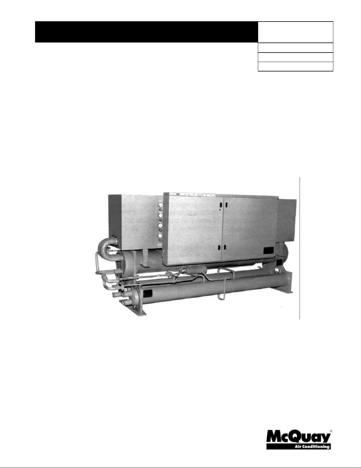
Reciprocating Chillers
WHR 017EW To WHR 210EW, Packaged Water-Cooled
WHR 017EA To WHR 210EA, Remote Condenser
17 to 210 Tons, 60 to 740 kW
R-22, R134a
60 Hz
PM WHR-2
Group: Chiller
Effective: May 2000
Supersedes: PM WHR-1
© 1997 McQuay International
Page 2

Table of Contents
Introduction......................................................................................................................................3
Features and Benefits.....................................................................................................................4
Design Advantages ..........................................................................................................................6
Temperature Control ......................................................................................................................9
Standard Control.......................................................................................................................9
Optional Control........................................................................................................................9
Optional Network Master Panel............................................................................................12
Optional Remote Monitoring and Sequence Panel............................................................12
Monitor software.....................................................................................................................13
Open Protocol..........................................................................................................................13
MicroTech BACdrop Gateway..........................................................................................13
Selection Procedure......................................................................................................................14
EW Water-Cooled, R-22.........................................................................................................14
EW Water-Cooled, R-134a.....................................................................................................15
EA Remote Condenser, R-22.................................................................................................15
EA Remote Condenser, R-134a .............................................................................................17
Selection Adjustment Factors .....................................................................................................17
Ethylene and Propylene Glycol Factors...............................................................................17
Evaporator and Condenser Delta-T Factors .......................................................................18
Fouling Factor..........................................................................................................................18
Performance Data..........................................................................................................................19
EW Water-Cooled...................................................................................................................19
Part Load Data (EW Only).....................................................................................................25
EA Remote Condenser...........................................................................................................26
Pressure Drop Curves..................................................................................................................30
Electrical Data................................................................................................................................33
Field Wiring Diagram..............................................................................................................44
Physical Data..................................................................................................................................45
EW Water-Cooled...................................................................................................................45
EA Remote Condenser...........................................................................................................50
Dimensional Data..........................................................................................................................53
EW Water-Cooled...................................................................................................................53
EA Remote Condenser...........................................................................................................57
Sound Data......................................................................................................................................61
Application Data.............................................................................................................................65
Optional Features..........................................................................................................................69
Optional Remote Monitoring and Sequencing Panel (RMS)............................................69
Product Specifications..................................................................................................................71
Water-Cooled, WHR 017 through 030.................................................................................71
Water-Cooled, WHR 040E through WHR 210E..................................................................75
Remote Condenser Chiller, WHR 017 through 030............................................................80
Remote Condenser Chiller, WHR 040E - WHR 210E..........................................................84
Our Facility is
"McQuay" is a registered trademark of McQuay International
"Illustrations cover the general appearance of McQuay International products at the time of publication and we
reserve the right to make changes in design and construction at anytime without notice"
1997 McQuay International
ARI Certification Applies to EW
Water-Cooled Units Only
2 WHR 017E - 210E Product Manual WHR-2
Page 3
Introduction
McQuay International offers a complete line of water-cooled chillers from 17 to 2500 tons (60
to 8800 kW) utilizing reciprocating and centrifugal compressors.
The WHR packaged reciprocating compressor chillers are a product of the McQuay
commitment to offer energy efficient equipment design. A design approach carefully
combining high quality compressors, efficient shell-and-tube heat exchangers, and state-ofthe-art controls into a unit of uncompromised operating efficiency and reliability.
Model WHR-EW are equipped with factory-mounted water-cooled condensers.
Model WHR-EA have no condensers mounted and are intended for use with remote
evaporative or air-cooled condensers. See McQuay catalog PM ACAQ for a complete line of
matching air-cooled condensers.
Efficiency
• WHR-EW are in compliance with ASHRAE 90.1
• Cross-circuit compressor unloading
• Liquid subcooling
• Copeland DISCUS compressor
• Maximum capacity reduction
ARI Standard 550/590-98 Certified
The ARI Certification Program does not include chillers with remote condensers.
Therefore, Model WHR-EA, Remote Condenser Chillers, ratings are not ARI certified.
Model WHR-EW, Water-Cooled Chillers are ARI certified.
Reliability
• Rugged compressor design
• Factory installed operating and safety controls
Flexibility
• Complete factory assembly
• 25 available sizes
• Factory installed options
Serviceability
• Semi-hermetic compressors
• Suction and discharge service valves
• Dual refrigerant circuits (WHR040 and above)
Full Factory Testing
• Assures trouble-free start-up and operation
Product Manual WHR-2 3
Page 4

Features and Benefits
Efficiency
WHR-EW Water-Cooled and WHR-EA Air-Cooled, (depending on remote condenser selection) meet
ASHRAE 90-1 efficiency levels - the world’s standard for chiller efficiency.
The “E” vintage WHR-EA reciprocating chillers offer some of the highest operating efficiencies
available today through the use of highly efficient components and efficiency oriented packaging.
Operating economy at reduced load is increased by operating each refrigerant circuit partially
unloaded, rather than one circuit off and the other circuit fully loaded. At unloaded conditions each
compressor will operate at lower compression ratios with substantial power savings.
Optional steps of capacity reduction are accomplished by the most efficient method of cylinder
unloading in the industry today.
To McQuay, operating economy means more than just energy efficiency. The WHR chillers reduce
operating costs not only through energy efficiency, but by offering high unit reliability, easy
serviceability, full factory testing and the backing of a factory trained sales, service and parts
organization.
Flexibility
The WHR chillers come in 25 sizes between 17 and 210 nominal tons (60 and 710 kW). The small
capacity increments provide a selection that will closely match the required job capacity.
The WHR water chillers come completely factory assembled, piped, wired, and shipped in one piece;
ready for water piping and wiring connections. The EA remote condenser models are ready for field
piping to the remote condenser. Single main supply power terminal block can be supplied by one field
installed main supply power disconnect switch.
Many optional features can been added to fit your needs. A unit mounted non-fused disconnect
switch eliminates the need for a field installed disconnect. Phase failure/reversal protection, high
return water unloading, and acoustical sound enclosures around compressor are all optional features
that can be factory installed.
Reliability
The McQuay WHR chillers use the most advanced and efficient reciprocating compressors in the
industry, the Copeland DISCUS valve compressors. These heavy-duty, industrial quality, semihermetic compressors are designed for R 22 or R-134a.
All WHR chillers are factory run tested to assure unit functionality. All safety and operating controls
are checked and calibrated. Chillers for remote condensers are connected to slave condensers for
testing purposes. This extensive testing assures trouble-free start-ups.
To protect the unit from abnormal operating conditions, a complete set of safety controls for each
circuit is used. Safety controls include compressor crankcase heater(s), freeze protection
pressurestats (manual reset), oil switches (manual rest), high pressure safety switches (manual reset),
and compressor motor overload protectors. Standard operating controls include time delay relays for
20-second sequence starting of compressors, manual pumpdown switches, low pressure controls,
compressor lead-lag switches (WHR-040EW-210EW) and chilled water temperature controller. All
controls and wiring are completely factory labeled for ease of service.
4 Product Manual WHR-2
Page 5
Serviceability
Semi-hermetic, 1750 rpm induction type motors are employed. The motors are refrigerant gas cooled.
A finned motor housing helps dissipate motor heat. Solid-state modules in the motor terminal box
respond to temperature sensors imbedded in all three motor windings to provide inherent thermal
overload protection for all run and start conditions.
Serviceable compressors offer reduced
maintenance costs because if problems
develop with components such as oil
pumps, unloaders, and pistons, they
can be serviced in the field without
replacing the compressor. Both suction
and discharge service valves are
provided to allow isolation of the
compressor from the refrigerant circuit.
All multiple compressor units utilize
two independent refrigerant circuits.
Dual refrigerant circuits permit
shutdown and routine maintenance and
service of one circuit while the second
circuit maintains system operation
where two or more compressors are
supplied.
Refrigerants
Models WHR 017 through WHR 210 utilize R-22 as the standard refrigerant. Models WHR 040
through WHR 210 can be furnished with R-134a refrigerant.
Full factory testing
Extensive quality control checks and individual performance tests assure that the units will meet the
requirements of the application and start-up and perform reliably. EA remote condenser models are
shipped with a holding charge of refrigerant, EW water-cooled units are shipped with a complete
operating charge.
Each unit is pressure tested, evacuated and charged with refrigerant for test purposes. Extensive
quality control checks and individual unit performance tests, at full load, ensure that each control is
properly adjusted and operates correctly. EA remote condenser models are connected to factory slave
condensers for testing. Each unit is then rechecked for refrigerant leakage.
Code Approvals
All WHRhb units are constructed and/or rated with the latest ANSI/ASHRAE 15 Safety Code,
National Electrical Code and ASME Boiler and Pressure Vessel Code. All models are ETL approved or
cETL listed.
Product Manual WHR-2 5
Page 6

Design Advantages
Unit Arrangements
The McQuay water chillers are completely factory assembled, piped, wired and shipped in one piece,
ready for field connection of refrigerant (EA models) and water piping. Each unit consists of motor
compressors, insulated DX cooler and centralized electrical control panel containing all necessary
safety and operating controls, and compressor starting controls. Arrangement “EW” units come
complete with water-cooled condensers with integral subcooler circuits. Arrangement “EA” units are
provided without condensers to allow for remote installation of air-cooled or evaporative condensing
equipment.
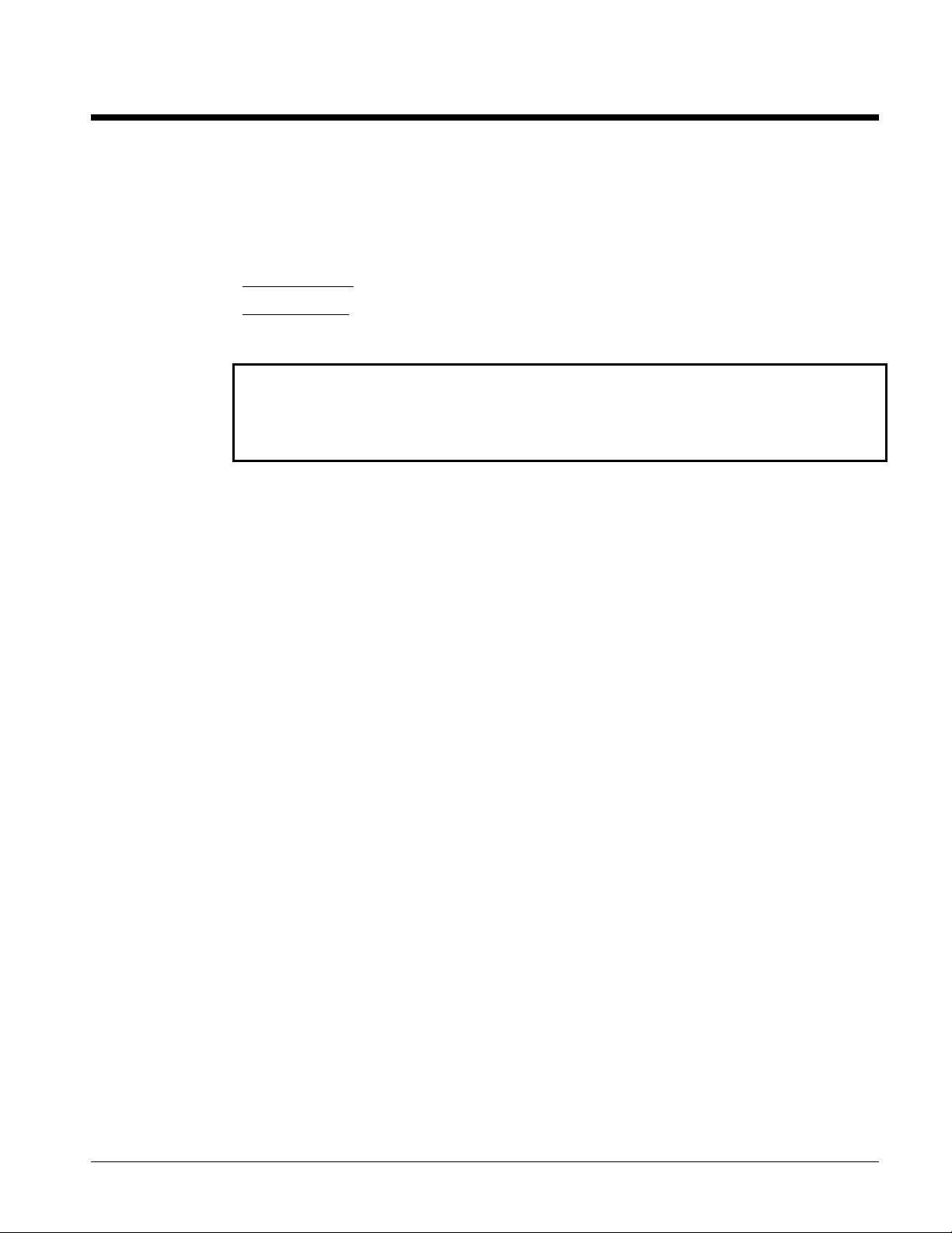
Compressors
WHR chillers use Copeland DISCUS semi-hermetic compressors. These compressors are designed
for R 22 and R-134a.
Semi-hermetic, 1750 rpm induction type motors are used. The motors are refrigerant gas cooled. Solidstate modules in the motor terminal box respond to temperature sensors imbedded in all three motor
windings, providing inherent thermal overload protection for all run and start conditions.
The compressor housing is constructed from close grained, high nickel content, alloy cast-iron with
no bolted joint between the motor and compressor. The housing includes a cast-iron cylinder head
and stator cover, and a crankcase oil sightglass. A suction strainer built into the compressor in the gas
stream between the suction service valve and the motor, filters out foreign and abrasive particles. An
internal relief valve relieves discharge pressure to the suction side for safety protection at high
compression ratios as required by ANSI/ASHRAE 15 Safety Code.
Main bearings are solid cast bronze insert type with oversized bearing area resulting in ultra-low
bearing loading.
The crankshaft is die-forged, high strength iron alloy with integral counterweights, statically and
dynamically balanced for smooth operation.
Connecting rods are lightweight aluminum with integral bearing surfaces on the crankshaft and piston
ends. Pistons are close grain cast iron with oil and compression rings. Piston pins are full floating
type for long life.
Compressors have a forced-feed lubrication system with positive oil displacement, a reversible oil
pump, and an operating oil charge. The pump feeds oil through rifle-drilled passages in the crankshaft
to all bearing surfaces. Magnetic plugs trap particles that enter the crankcase. The oil supply filters
through a large area oil strainer. During start-up, a crankcase heater minimizes oil being diluted by
refrigerant.
Factory Installed Liquid Line Components
Each refrigerant circuit has a filter-drier, liquid line sightglass/moisture indicator, solenoid valve,
manual liquid line shutoff valve and thermal expansion valve.
Short Circuit Protection
(WHR 017 through 030, WHR 095 through 210)
Each compressor is individually protected against short circuit and locked rotor conditions by factory
installed circuit breakers. Separate fusing protects the control circuit. WHR-040 through 090 can have
circuit breakers factory installed as an option.
6 Product Manual WHR-2
Page 7

Part Load Efficiencies
Part load efficiencies and Integrated Part Load Values (IPLV) for EW units are calculated according to
the requirements of the latest ARI Standard 550/590-98 and meet or exceed ASHRAE Efficiency
Standard 90.1. Since most air conditioning systems operate at less than design full load a majority of
the time, IPLV is an excellent method for comparing chillers' efficiencies.
Noise
All McQuay WHR chillers are equipped with hot gas discharge line mufflers in each refrigerant circuit
to reduce the overall sound levels. An optional insulated acoustical compressor enclosure to further
reduce sound levels is also available for most units. Sound level ratings are contained in the Sound
Rating section of this manual.
Unit Base
Designed for easy handling, the units are mounted on a compact, rugged formed steel base. Isolator
mounting holes are provided.
Electrical Control Center
Shipped with all operating and safety controls and motor starting equipment factory wired,
operationally tested, and ready for operation. All controls are centrally located in a hinged control
center with keylocked doors.
Part-winding starters are standard on 208/230 volt applications and available as a special on 460/575
volts. Across-the-line starters are standard on 380/460/575 volts.
A five-minute, solid-state lockout timer is provided to delay compressor restart after safety cutout or
power interruption, or under irregular cooling load demands. A lead lag switch is standard on all units
(WHR 040 – WHR 210) not incorporating the single circuit hot gas bypass option.
Evaporator
The evaporator is a direct expansion, shell-and-tube type with water flowing in the baffled shell side
and refrigerant flowing through the tubes.
The evaporator is constructed with a carbon steel shell and seamless high efficiency copper tubes,
roller expanded into heavy carbon steel tube sheets. Water baffles are polypropylene to resist
corrosion.
Refrigerant heads are carbon steel with multi-pass baffles to ensure oil return and are removable to
permit access to the tubes from either end. For water removal, 3/8" (10mm) vent and drain plugs are
provided on the top and bottom of the shell. Two 1/2” (12.7mm) couplings on each water nozzle allow
for easy field installation of sensor equipment.
The evaporator is wrapped with 3/4” (19.1mm) thick vinyl nitrate polymer sheet insulation. The
insulation has a K factor of 0.28 at 75°F (24°C). The insulation is fitted and cemented in place, then
painted with a resilient vinyl base paint to resist cracking.
The tube side maximum working pressure is 225 psig (1552kPa). The waterside working pressure is 175
psig (1206kPa). All evaporators are designed, constructed, inspected and stamped according to the
requirements of the ASME Boiler and Pressure Vessel Code.
Product Manual WHR-2 7
Page 8
Water-Cooled Condensers
All water-cooled condensers are cleanable shell and tube type with water in the tubes and refrigerant
in the shell. Each condenser is capable of holding the circuit pumpdown capacity. Independent
condensers serve the dual refrigerant circuits.
Each condenser is constructed with a carbon steel shell and seamless integrally finned high efficiency
copper tubes roller expanded into steel tubesheets. Water heads have vent and drain connections
and are removable. Also included is a liquid shutoff valve, purge valve, 450 psi (3104 kPa) relief valve
per ANSI/ASHRAE Pressure Vessel Code, Section VIII.
Water side working pressure is 225 psi (1550 kPa), refrigerant side is 450 psi (3104 kPa).
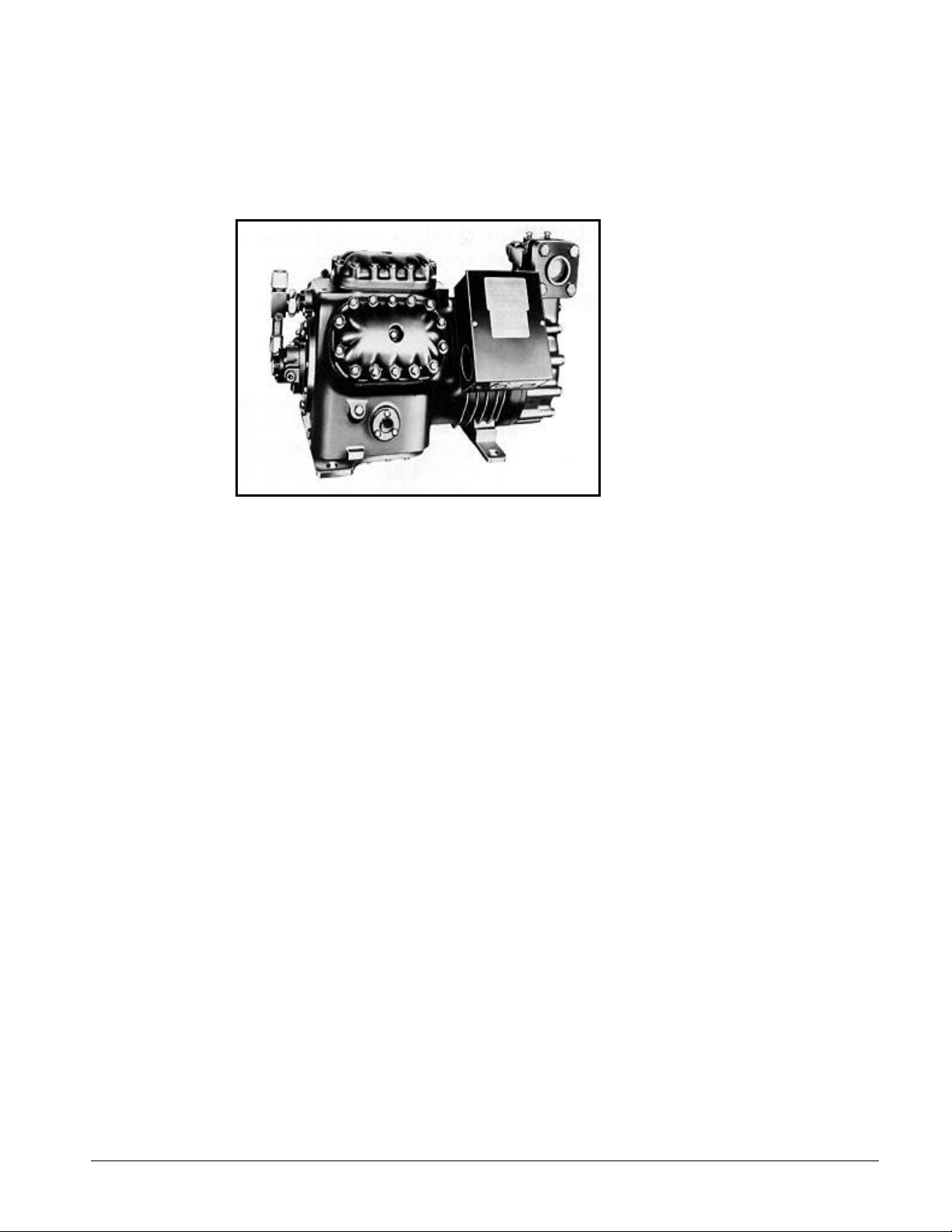
Air-Cooled Condensers
The WHR-EA chillers are designed for use with
properly sized and configured remote air-cooled or
evaporative condensers. The McQuay AC/AQ line of
air-cooled condensers are designed for use with these
chillers. The AC/AQ condensers are available with
single or double row vertical discharge fans and are
fully described and rated in Product Manual PM
ACAQ. They are packed with features offering
tangible benefits to owners.
• Complete range of capacities from 10 to 210 tons
• Circuits matched to WHR chillers
• Direct drive fan motors at 1140 and 830 RPM
• Patented floating tube design to eliminate tube sheet leaks
• High efficiency coil and fan motor design
• Internal baffles between all fan cells
• Weatherproof control panel with door mounted disconnect switch
• G90 painted galvanized steel cabinets
• Single point power connection
• Independent fusing and contactors for each fan motor
• Integral pre-piped subcooler circuit
8 Product Manual WHR-2
Page 9

Temperature Control
The McQuay WHR-040EW through 210EW water chillers are available with any one of three
different temperature controls to satisfy your requirements: 1) the standard microprocessor leaving
water controller, 1a) the same controller but with an indicator light package, and 2) the MicroTech
Controller.
Standard Control
WHR-017 - 030
A return water electromechanical temperature controller is supplied on the WHR-17 through 030
when supplied with two stages. Three stage units are supplied with a solid state, return water
temperature controller.
On Model EA units for remote condensers this controller is equipped with terminals from which the
first fan motor can be energized on compressor start. These sizes have a single refrigerant circuit.
WHR 040 - 210
The UNT-33 microprocessor leaving water temperature controller is standard on all units from size
040 to 210 and provides precise temperature control based on leaving water temperature. The
control is preset and calibrated and no other adjustment is required other than setpoint. There is a
60 second interstage On Delay between stages. Each stage incorporates minimum on and off timers
with a maximum cycle rate of six cycles per hour. Reset of supply water temperature can be
accomplished from outside air temperature, zone temperature or a signal from an EMS system.
Condenser fan control (Model EA)
Some means of controlling discharge pressure is required on condensers applied to the WHR-EA
remote condenser units. The McQuay AC/AQ air-cooled condensers can be equipped with
pressure activated fan cycling switches or with variable speed drives. Neither method requires
interconnecting wiring between the chiller and condenser.
Optional Control
Optional Zone Terminal for use with the UNT Control
Provides for onboard (or remotely wired) monitoring or adjusting of certain functions.
• Monitoring
• Monitor up to three setting or sensed values
• Monitor 18 different on/off inputs
• Monitor alarm status via a flashing alarm light and flashing symbol
• Adjusting, allows adjustment of any flashing set points, three at a time, typically set up so that
the relationship between values can be viewed simultaneously. For example:
• Display 1 = Lvg Water temp
• Display 2 = Lvg Water SP
• Display 3 = % Unit Load
Product Manual WHR-2 9
Page 10
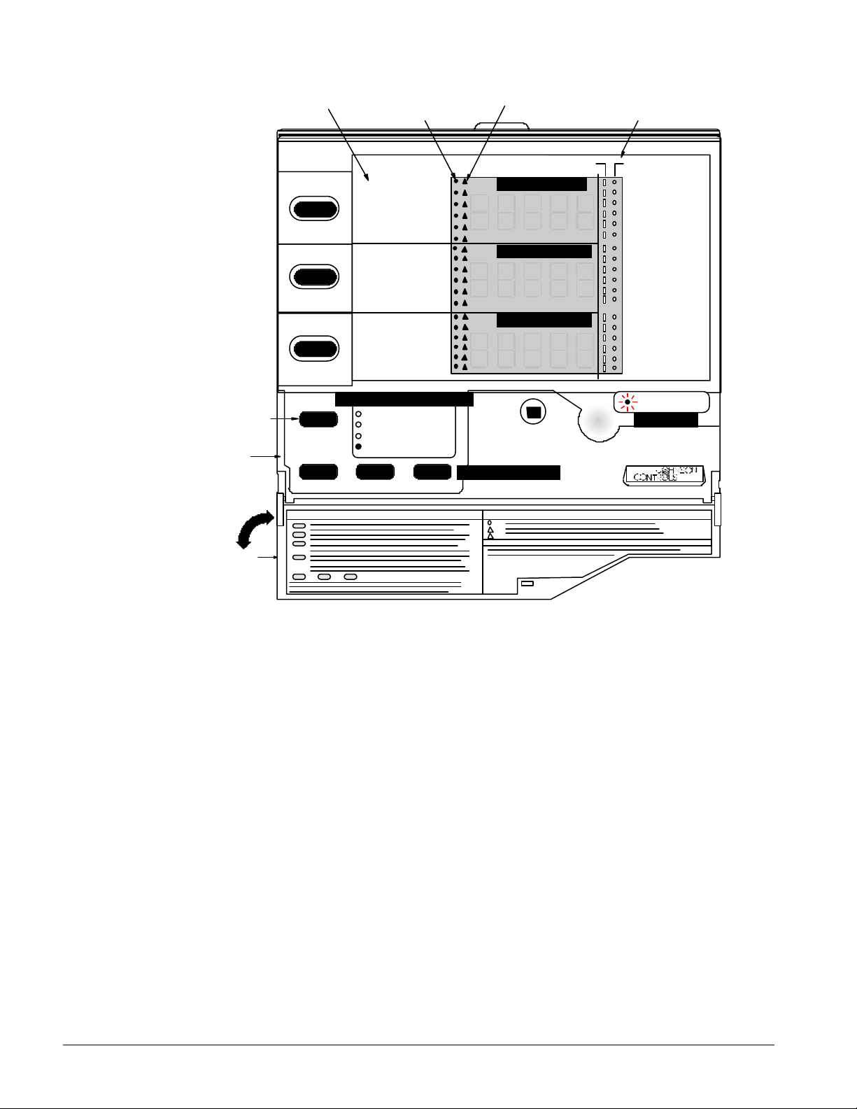
Figure 1, Zone Terminal Configuration
Display Item List
Display Indicator Dot
Warning Signal
On/Off Status
Display
Button 1
Mode
Selector
Button
Mode
Selector
Panel
Door
2
3
McQuay AGZ/AGR Global Chiller
Lvg Water Temp
Evap Pres #1
Evap Pres #2
OA/AI3 Input
OA/AI3 HiLimSP
OA/AI3 ResetSP
Lvg Water SP
LvgWtr RBnd SP
Contrl Band SP
Actual Lvg SP
Unoccpd Lvg SP
OA Lockout SP
% Unit Load
Lvg Low Lim SP
SoftSta Capcty
SoftStart Time
Cir #1 Starts
Cir #2 Starts
Opera ting Mode Indicator
MONITOR
ADJUST
TIME SCHEDULE
PASSWORD
ENTER
INSERT 10
Display Area 11
Display Area 21
Display Area 31
Up/Do wn Arrow K eys
ON OFF
Occupied
Flow Failure
OA Lockout
Cir#2Lead=On
Pmp/Stp #1=0
Pmp/Stp #2=0
Solenoid #1
Solenoid #2
Frzstat#1Alm
Frzstat#2Alm
MinLowPres#1
MinLowPres#2
Compressor 1
Compressor 2
Stage 3
Stage 4
Stage 5 Opt.
Stage 6 Opt.
Alarm Light
ALARM
AGZ-AGR
Optional MicroTech Chiller Controller
WHR-040 – 210 Only
The MicroTech reciprocating chiller controller surpasses all other microprocessor-based chiller
control systems available today. This powerful, user-friendly control system provides the flexibility
and performance needed for a stand-alone unit as well as multiple units tied into a network system.
MicroTech’s state-of-the-art design will not only permit your chiller to run more efficiently, but will
also simplify troubleshooting if a system failure occurs. Every MicroTech controller is programmed
and tested prior to shipment to ensure a trouble-free start-up.
Condenser fan control (Model EA)
Control of condenser fans is available through the MicroTech controller. The control steps
condenser fans or groups of fans based on discharge pressure. Field wiring is required between
the chiller and the remote condenser.
10 Product Manual WHR-2
Page 11

Operator-friendly
The 12-key, touch-sensitive, membrane keypad and 32-character display makes the MicroTech
system especially user-friendly. Inch-pound or SI units are optionally available.
The MicroTech menu structure is separated into three distinct categories, which provide the
operator or service technician with a full description of current unit status, control parameters, and
alarms. Security protection prevents unauthorized changing of the setpoints and control
parameters.
MicroTech continuously performs self-diagnostic checks, monitoring all system temperatures,
pressures and safeties, and will automatically shutdown a compressor, a refrigerant circuit of the
entire unit should a fault occur. The cause of the shutdown will be retained in memory and can be
easily displayed in plain English or metric units for operator review. The MicroTech chiller
controller can also retain and display the time the fault occurred and the operating conditions that
were present at the time of the fault, which is an extremely useful feature for troubleshooting. In
addition to displaying alarm diagnostics, the MicroTech chiller controller also provides the operator
with a warning of pre-alarm conditions.
Ice storage
The MicroTech control easily changes the leaving fluid setpoint via a remote signal to the
controller. The feature enables selection of chilled water or ice storage mode.
Enhanced chiller operating efficiencies
The MicroTech chiller controller offers many features to improve the operating efficiency of the
reciprocating chiller. In addition to monitoring water temperature and air temperatures, refrigerant
temperatures and pressures, and unit amperage, MicroTech also offers the following energy saving
features:
Programmable setpoints
The MicroTech chiller controller offers precise digital settings of the leaving chilled water
temperature setpoint and all other control parameters. This is extremely important in the setting of
safeties such as low leaving water temperature cutout, high pressure cutout, suction pressure
cutout, and freeze protection.
Compressor soft loading
Soft loading limits the number of cooling stages to prevent unnecessary electrical demand and
possible overshoot of the leaving chilled water temperature setpoint.
Demand limit control
Based on a 4-20mA DC signal, the controller will determine the maximum number of stages permitted
to operate, preventing additional demand charges during high usage periods.
Product Manual WHR-2 11
Page 12

Automatic circuit lead-lag
With the keypad, the operator can manually select either refrigerant circuit for the lead position or
the controller will automatically select the lead circuit based on the circuit with the fewest operating
hours.
Time clock, daily and holiday start/stop control
The operator can program daily start/stop schedules including weekends and up to fourteen
separate holidays without the need of an external time clock or EMS interface. If desired, an
external time clock can be used instead of the internal schedule.
Chilled water pump control
There is no need for an external time clock or EMS interface to control the pump start/stop
operation. The MicroTech chiller controller can accomplish this through a digital output. If an
alarm shuts down the chiller, the chilled water pump will remain on, providing any remaining cooling
to the loads.
Optional Network Master Panel
The MicroTech Network Master Panel (NMP) allows multiple reciprocating chiller controllers to be
incorporated into a building-wide network with other MicroTech units and auxiliary controllers. In
conjunction with a personal computer, it provides the building operator with the capability to
perform advanced equipment control and monitoring from a central or remote location. The
following features are provided by the optional NMP:
• Remote unit monitoring
• Advanced scheduling features
• Advanced alarm management features
• Global operator override
• Global unit shutdown input
• Demand metering
• Historical electrical data logging
Optional Remote Monitoring and Sequence Panel
One to three reciprocating chiller controllers can be incorporated into a network with the MicroTech
remote monitoring and sequencing (RMS) panel. The optional RMS panel provides the following
features:
• Remote chiller monitoring (up to 3)
• Automatic or manual chiller sequencing
• Automatic or manual lead-lag designation
• Common chiller scheduling
• Optimal start control
• Chilled water reset by outdoor air temperature or external 4-20 mA signal
• Chiller run time totalization by month, current year, and prior year
• Cooling degree-day totalization by month, current year, and prior year
The RMS panel is equipped with a keypad/display that is identical to the chiller controller’s
keypad/display. With a special keystroke combination, the RMS keypad/display can be interfaced
with any chiller controller. It then operates identical to the chiller-mounted keypad/display. Thus
the operator has full access to all networked chillers from a single remote location. Panel-mounted
LED’s clearly indicate which controller the RMS panel keypad/display is currently interfaced with.
12 Product Manual WHR-2
Page 13

Monitor software
When properly equipped with MicroTech Monitor software, a direct or remote connected PC can be
used for monitoring unit operation, changing setpoints, scheduling, trend logging, downloading
controller software, and diagnostics. For MicroTech network systems, the PC gives the operator
access to all unit and auxiliary controllers in the network. Specific controller or global data can be
displayed as desired. All keypad status information and control capability is available at the PC in a
full-screen format. Many additional unit control parameters, which are not available at the unit
controller’s keypad, are also available. Monitor software provides the following features:
• High resolution, unit-specific graphic representations
• One-touch function keys
• Multiple unit display screen
• Automatic screen refresher
• Help text
• Dial-up communications
• Alarm monitoring and management
• Scheduling
• Trend logging
• Downloading capability
• Multi-level password protection
• Controller Diagnostics
Open Protocol
MicroTech Open Protocol Master panel provides an interface between MicroTech unit controllers
and virtually all building automation systems (BAS). A protocol is a set of rules governing data
exchange between microprocessors, thereby permitting communications between unlike controllers.
As a result, building designers, owners and operators can obtain the advantages of McQuay
equipment, and the control versatility MicroTech has to offer. A low cost site license covering any
and all McQuay product is required.
MicroTech BACdrop Gateway
The McQuay BACdrop Gateway panel allows any BACnet based building automation system
(BAS) to communicate with MicroTech controllers. The panel translates between the standard
BACnet protocol (ANSI/ASHRAE 135-1995) and the MicroTech protocol. No modifications to the
MicroTech hardware or software are necessary. Since BACnet is a standard, public protocol no
license agreement is necessary.
Product Manual WHR-2 13
Page 14

Selection Procedure
EW Water-Cooled, R-22
1. Ratings are based and certified in accordance with ARI Standard 550/590-98.
2. Ratings in Table 5 through Table 10 may be interpolated for any chiller water temperature
between 40°F and 50°F (4.4°C and 10.0°C) but cannot be extrapolated.
3. Chilled water quantities - Ratings are based on a 10 degree F (5.6 degree C) chilled water range
(2.4 gpm/ton) and can be used for a delta-T range of 6 to 16 degrees F (3.3 to 8.8 degrees C) by
adjustments from Table 3.
4. Figure 2 through Figure 4 give the evaporator water pressure drop data. Water flow rates
should be maintained within these limits, which are based on minimum and maximum flow.
5. Ratings are based on 0.0001 fouling factor for the evaporator. For other fouling factors,
multiply ratings by evaporator factors from Table 3. For applications using a glycol solution,
see Table 1 and Table 2.
6. Ratings are based on condenser flow of 3 gpm/ton (10 degree F, 5.6 degree C delta-T) and
0.00025 fouling factor. Corrections for other conditions are in the following Application
Section.
Selection Procedure
Knowing the required chiller capacity in tons, the leaving water temperature and either the chilled
water temperature range (Delta T) or the flow, determine the unknown quantity using the formula:
= Tons
Knowing the required chiller capacity (tons), the entering condenser water temperature, and either
the condenser water temperature range-delta T, or the GPM, determine the unknown quantity using
the formula:
With the above data, the appropriate unit can be selected from Table 5 through Table 10. Pressure
drop for evaporators and condensers can be found in Figure 2 through Figure 4.
24
TDeltaGPM ×
=GPM Condenser
THR
×
=
.Cond TDelta500
aterRangeCondenserW
30Capacity Cooling Tons Nominal
×
Sample Selection
Given: Cool 165 GPM of water from 54°F to 44°F with condenser water available at 85°F.
Condenser water temperature rise to be 10 degrees. Fouling factor of 0.0001 in the evaporator and
0.00025 in the condenser.
Find:
A. WHR packaged water chiller selection
B. Compressor power input
C. Condenser water flow rate
D. Evaporator and condenser water pressure drop
14 Product Manual WHR-2
Page 15

Solution:
1. Chilled water range: 54°F - 44°F = 10°F (Temperature Difference).
2.
3. From Table 6, a model WHR-070EW has the capacity to meet the job requirement. For an
evaporator leaving water temperature of 44°F and condenser water entering temperature of
85°F with a 10 degree rise, the unit capacity rating table indicates:
Capacity: 70.5 Tons
Power: 62.4 kW
4. Determine condenser water from the following:
Condenser GPM =
5. From Figure 2 for the WHR-070EW, evaporator pressure drop at 165 GPM is 6.2 feet
6. From Figure 3, the condenser pressure drop at 210.6 GPM is 12.5 feet water.
×
=Capacity
24
Tons Cooling Capacity 30
Nominal Condenser Water Range
Range Water ChilledGPM
165 1024×
= 68.8 tons
×
30 tons70.5
= =
×
degrees 10
GPM 211
EW Water-Cooled, R-134a
Use the same selection procedures as with R-22 except multiply the values in the R-22 Performance
Tables as follows: Capacity x 0.68, Power x 0.65, EER x 1.05.
EA Remote Condenser, R-22
Selection Method
The performance of the WHR chillers is listed by LWT (leaving chilled water temperature) and by
Condensing Temperature. Tons, Power, and THR (Total Heat Rejection) are given. This data can
then be used to select any condenser from its own capacity data. For a McQuay AC/AQ air-cooled
condenser, use product manual PM ACAQ.
1. Ratings may be interpolated for any chiller water temperature between 42°F and 50°F but
cannot be extrapolated (contact factory for ratings outside this range).
2. Chilled water quantities - Ratings are based on a 10 degree F chilled water range and are
applicable from a minimum of 6 degrees F to a maximum of 16 degrees F differential between
entering and leaving chilled water temperatures.
3. Ratings are based on .00025 fouling factor for both condenser and evaporator. For other
fouling factors, multiply ratings by cooler factors from Table 3 and Table 4. For applications
using a glycol solution, see Table 1 and Table 2.
Selection Procedure
Normally the required chiller capacity in tons, the entering and leaving chilled water temperature
and flow and the design outdoor air temperature are known. Determine any unknown quantity
using the formula:
Tons = gpm x delta T / 24
Capacity data is in Table 12 and Table 13 for IP units and Table 14 and Table 15 for SI units. Rating
are based on:
• Leaving chilled water temperatures from 42°F to 50°F (6°C to 10°C) with a 10 degree delta-T.
Selections can be interpolated between these leaving temperatures but not extrapolated.
Product Manual WHR-2 15
Page 16

Correction factors for delta-Ts other than 10 degrees are in Table 3 and Table 4. Exceeding the
Delta-T range of 6 to 16 degrees will cause problems controlling unit unloading.
• Condensing temperatures (CT) from 105°F to 125°F (40°C to 55°C).
• Total Heat Rejection (THR) is given and used to select the condenser, whether it be a dry air-
cooled condenser or an evaporative condenser.
Several different size condensers can usually be matched to any given WHR-EA unit depending on
the condensing temperature that typically ranges from 20 to 30 degrees F above the design outdoor
temperature. Increasing condensing temperatures will reduce the chiller capacity, increase its power
consumption and result in a smaller condenser being required.
Normally a WHR-EA is selected to meet or exceed the required cooling capacity at some
condensing temperature and a condenser then selected with sufficient capacity to handle the heat
rejection with the selected temperature difference (TD, difference between design outdoor dry bulb
temperature and condensing temperature).
A more accurate solution can be achieved by plotting the capacity of the chiller and the condenser
as a function of the TD and observing the curves intersection that is the system balance point. An
example is shown in the following "Selection Example" section.
Sample Selections
Given: Required capacity of 100 tons cooling 240 gpm of water from 54°F to 44°F with 95°F design
dry bulb temperature. Evaporator fouling factor of .00025.
Find:
1. WHR water chiller and AC/AQ condenser selection
2. Compressor power input, chilled water pressure drop
Solution:
1) From Table 13, several WHR selections are possible:
a) WHR 110EA at 110°F CT; 102.5 tons, 107.3 kW, 1596.5 THR, 1.05 kW/ton
b) WHR 115EA at 115°F CT; 101.0 tons, 112.8 kW, 1597.3 THR, 1.12 kW/ton
c) WHR 120EA at 125°F CT; 103.4 tons, 135.1 kW, 1701.5 THR, 1.30 kW/ton
Note that the condensing temperature has significant influence on the chiller efficiency.
Progressing from a) to c) above will require smaller condensers, offset by larger, more
expensive chillers and lessening efficiency.
2) A condenser can be selected with the above information. For this example, a McQuay Model
ACAQ air-cooled condenser will be selected using selection procedures and data contained in
Product Manual PM ACAQ. A model ACD (double row of fans, standard fan speed) will be
used.
a) For the WHR 110EA at a TD of 15 degrees F (110°F - 95°F) no selection appears possible
based on the simple selection method. However, it is close and the graphical method may
give a solution.
b) For the WHR 115EA at a TD of 20 degrees, a Model 175A will do the service.
c) For the WHR 120 EA at a TD of 30 degrees, a Model 115A will do the service.
Selection c) will prove to be considerably lower in first cost but carries a 16 percent efficiency
penalty.
16 Product Manual WHR-2
Page 17
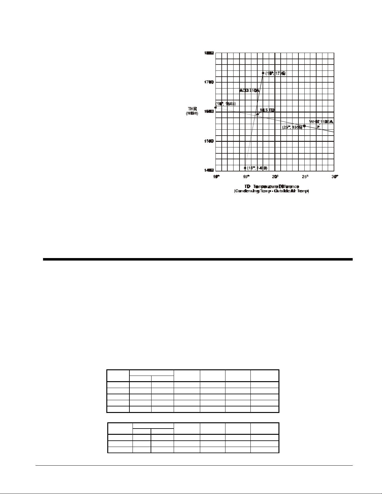
3) Graphical solution to Case a) is shown below.
d) The THR for the WHR
110EA is plotted using two
points; TD=10 degrees
(105°F-95°F) and TD=25
degrees (120°F-95°F).
e) The THR for the ACD 210A
is plotted using its capacity
at TD+15 degrees and
TD=18 degrees.
f) The curves intersect at
TD=16.5 degrees or 111.5°F
condensing temperature.
g) Extrapolating the WHR
capacity at 111.5°F gives
101.5 tons which will meet
the job requirements. It will
be the highest cost but
most efficient unit.
EA Remote Condenser, R-134a
Use the same selection procedures as with R-22 except multiply the values in the R-22 Performance
Tables as follows: Capacity x 0.68, Power x 0.65, EER x 1.05.
Selection Adjustment Factors
Ethylene and Propylene Glycol Factors
WHR units are designed to operate with a leaving chilled fluid temperature from 21°F (-6.1°C) to
60°F (16°C). Leaving chilled fluid temperatures below 40°F (4.6°C) result in suction temperatures at
or below the freezing point of water and a glycol solution is required. The use of glycol in the
evaporator will reduce the performance of the unit. The reduction in performance depends upon
the glycol concentration. This should be taken into consideration during initial system design.
McQuay encourages a minimum concentration of 25% be provided on all glycol applications.
Glycol concentrations below 25% are too diluted for long-term corrosion protection of ferrous
metals and corrosion inhibitors may need to be recalculated. Glycol in the condenser will have a
negligible effect on performance because glycol at higher temperatures will perform with
characteristics similar to water.
Table 1, Adjustment Factors for Ethylene Glycol
E.G
10 26 -3 0.991 0.966 1.013 1.070
20 18 -8 0.982 0.992 1.040 1.129
30 7 -14 0.972 0.986 1.074 1.181
40 -7 -22 0.961 0.976 1.121 1.263
50 -28 -33 0.946 0.966 1.178 1.308
Freeze PointPercent
°F °C
Table 2, Adjustment Factors for Propylene Glycol
P.G
10 26 -3 0.987 0.992 1.010 1.068
20 19 -7 0.975 0.985 1.028 1.147
30 9 -13 0.962 0.978 1.050 1.248
Freeze PointPercent
°F °C
Cap. Power Flow PD
Cap. Power GPM PD
Product Manual WHR-2 17
Page 18

40 -5 -21 0.946 0.971 1.078 1.366
NOTE: Glycol applications are not included in the ARI certification program.
Evaporator and Condenser Delta-T Factors
Performance tables are based on a 10°F (5°C) temperature difference through the evaporator and
condenser. A temperature difference other than 10°F (5°C) will result in unit performance being
different from what is shown. Adjustment factors for applications having temperature drops
between 6°F and 16°F (3.3°C to 8.9°C) can be found in Table 3 and Table 4.
Fouling Factor
Performance tables are based on water with a fouling factor of 0.0001 ft2 x hr x °F/BTU (0.0176 m2 x
°C/kW) in the evaporator and 0.00025 ft2 x hr x °F/BTU (0.044 m2 x °C/kW) in water-cooled
condensers according to ARI 550/590-98. As fouling is increased, performance decreases. See
Table 3 and Table 4 for performance with other fouling factors.
To ensure optimum unit operation, proper water treatment must be maintained. Scaling and dirt in a
system will vary significantly depending on local water conditions. Water treatment should be
based on characteristics of the area’s water. Improper or untreated water may lead to scale build up,
erosion and corrosion in both the condenser and evaporator. McQuay will not accept
responsibility for poorly or improperly treated water.
Table 3, Evaporator Adjustment Factors
Chilled Water
Delta-T
°F °C Cap. Power Cap. Power Cap. Power
6 3.3 0.992 0.995 0.985 0.993 0.962 0.986
8 4.4 0.995 0.997 0.988 0.995 0.965 0.988
10 5.6 1.000 1.000 0.993 0.998 0.970 0.991
12 6.7 1.005 1.002 0.998 1.000 0.975 0.993
14 6.8 1.010 1.005 1.003 1.003 0.980 0.996
16 8.9 1.014 1.007 1.007 1.005 0.984 0.998
0.0001 (0.0176) 0.00025 (0.044) 0.00075 (0.132)
Fouling Factor
Table 4, Condenser Adjustment Factors
Condenser
Water Delta-T
°° F °° C Cap. Power Cap. Power
6 3.3 1.003 0.999 0.984 1.035
8 4.4 1.002 1.000 0.982 1.037
10 5.5 1.000 1.000 0.980 1.038
12 6.6 0.984 0.973 0.977 1.042
14 7.7 0.976 0.960 0.963 1.067
16 8.8 0.968 0.946 0.948 1.092
0.00025 (0.044 0.00075 (0.132)
Fouling Factor
18 Product Manual WHR-2
Page 19
Performance Data
EW Water-Cooled
Table 5, WHR 017EW - WHR 060EW, 60 Hz, IP Units
WHR
017EW 44.0 19.1 11.8 18.3 18.2 13.2 15.6 17.7 13.9 14.4 16.7 15.4 12.4 15.7 16.7 10.7
020EW 44.0 23.4 15.7 17.1 22.3 17.5 14.6 21.7 18.4 13.5 20.5 20.3 11.6 19.3 22.1 10.1
025EW 44.0 29.2 19.8 17.0 27.8 22.1 14.5 27.0 23.3 13.4 25.5 25.7 11.5 24.0 28.0 10.0
030EW 44.0 32.6 22.0 17.1 31.0 24.5 14.6 30.2 25.8 13.5 28.5 28.5 11.6 26.8 31.0 10.1
040EW 44.0 41.6 27.2 17.8 39.3 30.2 15.1 38.0 31.7 14.0 35.9 34.6 12.1 33.7 37.6 10.4
045EW 44.0 48.2 30.9 18.2 45.5 34.3 15.4 44.0 36.0 14.3 41.6 39.3 12.4 39.1 42.7 10.7
050EW 44.0 56.4 38.7 17.0 53.3 43.0 14.5 51.5 45.1 13.4 48.7 49.3 11.6 45.7 53.5 10.0
060EW 44.0 64.1 42.0 17.8 60.5 46.7 15.1 58.5 49.0 14.0 55.3 53.6 12.1 51.9 58.1 10.4
Notes:
1. Bold box areas certified in accordance with ARI Standard 550/590-98.
2. Ratings based on HCFC-22, evaporator fouling of 0.0001, 2.4 gpm/ton; condenser fouling of 0.00025, 3 gpm/ton.
3. For 208V units multiply capacity and EER by 0.98.
4. Ratings are based on circuit #1 in lead position and circuit #2 in lag position.
5. Interpolation is allowed; extrapolation is not permitted. Consult McQuay for performance outside the ratings shown.
6. For LWT of 40°F and below please refer to Application Adjustment Factors section.
SIZE
LWT
(°F)
40.0 17.8 11.7 17.1 16.9 13.1 14.7 16.5 13.7 13.7 15.6 15.0 11.8 14.6 16.3 10.2
42.0 18.4 11.8 17.7 17.6 13.1 15.1 17.1 13.8 14.1 16.2 15.2 12.1 15.1 16.5 10.4
46.0 19.8 11.9 18.7 18.9 13.3 16.0 18.3 14.0 14.8 17.3 15.5 12.6 16.3 17.0 10.9
48.0 20.4 11.9 19.4 19.5 13.3 16.6 19.0 14.1 15.3 18.0 15.6 13.1 16.9 17.1 11.3
50.0 21.2 12.0 19.9 20.1 13.5 17.0 19.6 14.2 15.7 18.6 15.8 13.4 18.1 17.4 11.7
40.0 21.8 15.5 16.1 20.7 17.3 13.8 20.2 18.2 12.8 19.1 19.9 11.1 17.9 21.6 9.6
42.0 22.6 15.6 16.6 21.5 17.4 14.2 20.9 18.3 13.2 19.8 20.1 11.3 18.6 21.8 9.8
46.0 24.3 15.7 17.6 23.1 17.6 15.0 22.5 18.6 13.9 21.2 20.5 11.9 20.0 22.4 10.3
48.0 25.1 15.8 18.2 23.9 17.7 15.5 23.3 18.7 14.3 22.0 20.7 12.3 20.7 22.6 10.6
50.0 26.0 15.8 18.7 24.7 17.8 15.9 24.1 18.8 14.7 22.8 20.9 12.6 22.1 23.0 10.9
40.0 27.1 19.6 15.9 25.8 21.9 13.7 25.1 23.0 12.7 23.8 25.2 11.0 22.3 27.4 9.5
42.0 28.1 19.8 16.5 26.8 22.0 14.1 26.1 23.2 13.1 24.7 25.4 11.3 23.1 27.6 9.7
46.0 30.2 19.9 17.4 28.8 22.3 14.9 27.9 23.5 13.7 26.3 25.9 11.8 24.8 28.4 10.2
48.0 31.2 19.9 18.1 29.7 22.4 15.4 28.9 23.6 14.2 27.4 26.2 12.2 25.8 28.7 10.5
50.0 32.4 20.1 18.6 30.7 22.6 15.8 29.9 23.8 14.6 28.4 26.5 12.5 27.5 29.1 10.9
40.0 30.4 21.7 16.1 28.8 24.3 13.8 28.1 25.5 12.8 26.6 27.9 11.1 24.9 30.3 9.6
42.0 31.4 21.9 16.6 30.0 24.4 14.2 29.1 25.7 13.2 27.6 28.1 11.3 25.8 30.6 9.8
46.0 33.8 22.1 17.6 32.2 24.6 15.0 31.3 26.0 13.9 29.4 28.7 11.9 27.8 31.5 10.3
48.0 34.9 22.1 18.2 33.2 24.8 15.5 32.4 26.2 14.3 30.7 29.0 12.3 28.8 31.7 10.6
50.0 36.2 22.2 18.7 34.3 25.0 15.9 33.5 26.3 14.7 31.7 29.3 12.6 30.8 32.3 10.9
40.0 38.8 26.8 16.8 36.6 29.7 14.3 35.5 31.1 13.3 33.5 33.9 11.5 31.3 36.6 9.9
42.0 40.2 27.0 17.2 38.0 30.0 14.7 36.9 31.4 13.7 35.1 34.3 11.8 32.5 37.1 10.2
46.0 43.1 27.5 18.3 40.8 30.5 15.5 39.6 32.0 14.4 37.3 35.0 12.5 35.0 38.0 10.6
48.0 44.6 27.6 18.8 42.2 30.7 16.0 41.0 32.3 15.2 38.7 35.4 12.7 36.3 38.5 11.0
50.0 46.1 27.7 19.3 43.7 31.0 16.5 42.5 32.6 15.2 40.0 35.8 13.0 37.5 38.9 11.3
40.0 44.9 30.4 17.1 42.4 33.7 14.6 41.1 35.4 13.6 38.8 38.5 11.7 36.3 41.6 10.2
42.0 46.5 30.7 17.6 44.0 34.0 15.0 42.7 35.6 14.0 40.7 39.0 12.0 37.6 42.1 10.4
46.0 49.9 31.2 18.7 47.2 34.6 15.9 45.9 36.4 14.7 43.2 39.8 12.7 40.5 43.2 10.9
48.0 51.6 31.3 19.2 48.8 34.9 16.4 47.5 36.7 15.5 44.8 40.2 13.0 42.0 43.7 11.2
50.0 53.4 31.5 19.7 50.6 35.2 16.8 49.2 37.0 15.5 46.3 40.6 13.3 43.5 44.2 11.5
40.0 52.5 38.1 16.0 49.6 42.3 13.7 48.2 44.3 12.7 45.4 48.2 11.0 42.4 52.1 9.5
42.0 54.4 38.5 16.5 51.5 42.6 14.1 50.0 44.6 13.1 47.6 48.8 11.3 44.0 52.8 9.8
46.0 58.5 39.1 17.5 55.3 43.3 14.9 53.7 45.6 13.8 50.5 49.8 11.9 47.4 54.1 10.2
48.0 60.4 39.2 18.0 57.2 43.7 15.3 55.6 46.0 14.5 52.4 50.4 12.2 49.2 54.8 10.5
50.0 62.5 39.5 18.5 59.2 44.1 15.7 57.6 46.4 14.5 54.2 50.9 12.5 50.9 55.4 10.8
40.0 59.7 41.4 16.8 56.3 45.9 14.3 54.7 48.1 13.3 51.5 52.4 11.5 48.2 56.6 9.9
42.0 61.8 41.8 17.2 58.5 46.3 14.7 56.7 48.5 13.7 54.1 53.0 11.8 50.0 57.3 10.2
46.0 66.4 42.4 18.3 62.8 47.1 15.5 61.0 49.5 14.4 57.4 54.1 12.5 53.8 58.8 10.6
48.0 68.6 42.6 18.8 64.9 47.5 16.0 63.2 50.0 15.2 59.6 54.7 12.7 55.9 59.5 11.0
50.0 71.0 42.9 19.3 67.2 47.9 16.5 65.4 50.4 15.2 61.6 55.3 13.0 57.8 60.2 11.3
70°F 80°F 85°F 95°F 105°F
Cap. PWR Cap. PWR Cap. PWR Cap. PWR Cap. PWR
Tons kWi
EER
Tons kWi
Entering Condenser Water Temperature (10°F Delta T.)
EER
Tons kWi
EER
Tons kWi
EER
Tons kWi
EER
Product Manual WHR-2 19
Page 20
Table 6, WHR 070EW - WHR 120EW, 60 Hz, IP Units
WHR
LWT
SIZE
070EW 44.0 77.2 53.5 17.0 73.0 59.5 14.5 70.5 62.4 13.4 66.7 68.2 11.6 62.6 74.0 10.0
080EW 44.0 83.8 58.2 16.9 79.2 64.8 14.4 76.5 67.9 13.3 72.4 74.2 11.5 67.9 80.6 9.9
085EW 44.0 93.1 62.2 17.7 88.0 69.3 15.0 85.0 72.6 13.9 80.4 79.4 12.0 75.5 86.1 10.4
090EW 44.0 100.2 65.5 18.0 94.7 72.9 15.3 91.5 76.4 14.2 86.6 83.5 12.3 81.3 90.6 10.6
095EW 44.0 104.0 68.9 17.9 98.7 77.2 15.1 96.0 81.3 14.0 90.6 89.5 12.0 85.0 97.4 10.4
100EW 44.0 110.5 73.2 17.9 104.9 82.0 15.1 102.0 86.4 14.0 96.3 95.1 12.0 90.3 103.6 10.4
110EW 44.0 120.8 81.2 17.6 114.6 91.0 14.9 111.5 95.9 13.8 105.3 105.6 11.8 98.7 114.9 10.2
115EW 44.0 122.9 81.3 17.9 116.7 91.1 15.1 113.5 96.0 14.0 107.1 105.7 12.0 100.4 115.1 10.4
120EW 44.0 132.1 89.2 17.6 125.4 99.9 14.9 122.0 105.3 13.8 115.2 115.9 11.8 108.0 126.2 10.2
Notes:
1. Bold box areas certified in accordance with ARI Standard 550/590-98.
2. Ratings based on HCFC-22, evaporator fouling of 0.0001, 2.4 gpm/ton; condenser fouling of 0.00025, 3 gpm/ton.
3. For 208V units multiply capacity and EER by 0.98.
4. Ratings are based on circuit #1 in lead position and circuit #2 in lag position.
5. Interpolation is allowed; extrapolation is not permitted. Consult McQuay for performance outside the ratings shown.
6. For LWT of 40°F and below please refer to Application Adjustment Factors section.
(°F)
40.0 71.9 52.8 16.0 67.9 58.5 13.7 65.9 61.3 12.7 62.1 66.7 11.0 58.1 72.1 9.5
42.0 74.5 53.2 16.5 70.5 59.0 14.1 68.4 61.8 13.1 65.1 67.5 11.3 60.3 73.0 9.8
46.0 80.0 54.0 17.5 75.6 60.0 14.9 73.5 63.0 13.8 69.2 69.0 11.9 64.9 74.9 10.2
48.0 82.7 54.3 18.0 78.3 60.5 15.3 76.1 63.6 14.5 71.8 69.7 12.2 67.3 75.8 10.5
50.0 85.5 54.6 18.5 81.0 61.0 15.7 78.8 64.2 14.5 74.2 70.4 12.5 69.7 76.6 10.8
40.0 78.0 57.4 15.9 73.7 63.6 13.6 71.5 66.7 12.6 67.4 72.6 10.9 63.0 78.4 9.4
42.0 80.9 57.9 16.4 76.5 64.2 14.0 74.2 67.2 13.0 70.7 73.5 11.2 65.4 79.4 9.7
46.0 86.8 58.8 17.4 82.1 65.3 14.8 79.8 68.6 13.7 75.0 75.0 11.8 70.4 81.5 10.1
48.0 89.7 59.1 17.8 84.9 65.9 15.2 82.6 69.3 14.4 77.9 75.8 12.1 73.1 82.5 10.4
50.0 92.8 59.4 18.4 87.9 66.4 15.6 85.5 69.9 14.4 80.6 76.6 12.4 75.6 83.4 10.7
40.0 86.7 61.4 16.6 81.9 68.0 14.2 79.5 71.3 13.2 74.9 77.6 11.4 70.0 83.9 9.9
42.0 89.8 61.9 17.1 85.0 68.6 14.6 82.5 71.9 13.6 78.5 78.6 11.7 72.7 84.9 10.1
46.0 96.5 62.9 18.1 91.2 69.8 15.4 88.7 73.3 14.3 83.4 80.2 12.4 78.2 87.1 10.6
48.0 99.7 63.2 18.6 94.4 70.4 15.9 91.8 74.1 15.1 86.5 81.1 12.6 81.2 88.2 10.9
50.0 103.1 63.5 19.2 97.7 71.0 16.3 95.0 74.7 15.1 89.5 81.9 12.9 84.0 89.2 11.2
40.0 93.3 64.6 17.0 88.1 71.6 14.5 85.6 75.0 13.5 80.6 81.7 11.6 75.4 88.2 10.1
42.0 96.7 65.2 17.5 91.5 72.2 14.9 88.8 75.6 13.9 84.5 82.7 11.9 78.2 89.4 10.4
46.0 103.9 66.2 18.5 98.2 73.4 15.8 95.4 77.2 14.6 89.8 84.4 12.6 84.2 91.7 10.8
48.0 107.3 66.5 19.0 101.6 74.1 16.3 98.8 77.9 15.4 93.1 85.3 12.9 87.4 92.8 11.1
50.0 111.0 66.9 19.6 105.1 74.7 16.7 102.3 78.6 15.4 96.3 86.2 13.2 90.4 93.8 11.4
40.0 96.9 68.4 16.7 91.8 76.3 14.2 89.2 80.2 13.2 84.3 87.9 11.3 79.2 95.5 9.8
42.0 100.3 68.7 17.2 95.2 76.7 14.7 92.5 80.7 13.6 87.5 88.7 11.6 82.2 96.5 10.1
46.0 107.6 69.1 18.5 102.1 77.5 15.6 99.5 81.8 14.4 94.0 90.2 12.4 88.5 98.5 10.6
48.0 111.5 69.3 19.0 105.8 77.9 16.0 103.6 82.1 15.1 97.2 90.9 12.7 92.6 98.8 11.0
50.0 115.2 69.3 19.7 109.4 78.2 16.5 106.4 82.7 15.3 100.7 91.5 13.0 95.0 99.6 11.3
40.0 102.9 72.7 16.7 97.5 81.0 14.2 94.8 85.3 13.2 89.6 93.4 11.3 84.1 101.5 9.8
42.0 106.6 73.0 17.2 101.2 81.6 14.7 98.3 85.8 13.6 92.9 94.3 11.6 87.3 102.6 10.1
46.0 114.3 73.4 18.5 108.5 82.3 15.6 105.7 86.9 14.4 99.9 95.8 12.4 94.0 104.6 10.6
48.0 118.4 73.6 19.0 112.4 82.8 16.0 110.1 87.3 15.1 103.3 96.6 12.7 98.4 105.0 11.0
50.0 122.4 73.7 19.7 116.3 83.1 16.5 113.0 87.9 15.3 107.0 97.3 13.0 101.0 105.8 11.3
40.0 112.5 80.7 16.5 106.6 90.0 14.0 103.6 94.7 13.0 97.9 103.7 11.2 91.9 112.7 9.7
42.0 116.5 81.0 17.0 110.6 90.5 14.5 107.5 95.2 13.4 101.6 104.6 11.5 95.4 113.8 9.9
46.0 125.0 81.5 18.2 118.6 91.4 15.4 115.5 96.5 14.2 109.2 106.4 12.2 102.8 116.1 10.5
48.0 129.5 81.7 18.8 122.9 91.9 15.8 120.4 96.9 14.9 112.9 107.2 12.5 107.6 116.6 10.8
50.0 133.8 81.8 19.4 127.1 92.3 16.3 123.5 97.5 15.1 116.9 108.0 12.8 110.4 117.5 11.2
40.0 114.5 80.7 16.7 108.5 90.0 14.2 105.5 94.8 13.2 99.7 103.8 11.3 93.6 112.8 9.8
42.0 118.6 81.1 17.2 112.6 90.6 14.7 109.4 95.3 13.6 103.4 104.7 11.6 97.2 114.0 10.1
46.0 127.2 81.6 18.5 120.8 91.5 15.6 117.6 96.6 14.4 111.1 106.5 12.4 104.6 116.3 10.6
48.0 131.8 81.8 19.0 125.1 92.0 16.0 122.5 97.0 15.1 115.0 107.3 12.7 109.5 116.7 11.0
50.0 136.2 81.9 19.7 129.4 92.4 16.5 125.8 97.6 15.3 119.0 108.1 13.0 112.4 117.6 11.3
40.0 123.1 88.6 16.5 116.6 98.8 14.0 113.4 103.9 13.0 107.1 113.8 11.2 100.6 123.7 9.7
42.0 127.5 89.0 17.0 121.0 99.4 14.5 117.6 104.6 13.4 111.1 114.9 11.5 104.4 125.0 9.9
46.0 136.8 89.5 18.2 129.8 100.4 15.4 126.4 105.9 14.2 119.4 116.8 12.2 112.5 127.5 10.5
48.0 141.6 89.7 18.8 134.4 100.9 15.8 131.7 106.4 14.9 123.6 117.7 12.5 117.7 128.0 10.8
50.0 146.4 89.8 19.4 139.1 101.3 16.3 135.2 107.1 15.1 128.0 118.6 12.8 120.8 129.0 11.2
70°F 80°F 85°F 95°F 105°F
Cap. PWR Cap. PWR Cap. PWR Cap. PWR Cap. PWR
Tons kWi
EER
Tons kWi
Entering Condenser Water Temperature (10°F Delta T.)
EER
Tons kWi
EER
Tons kWi
EER
Tons kWi
EER
20 Product Manual WHR-2
Page 21
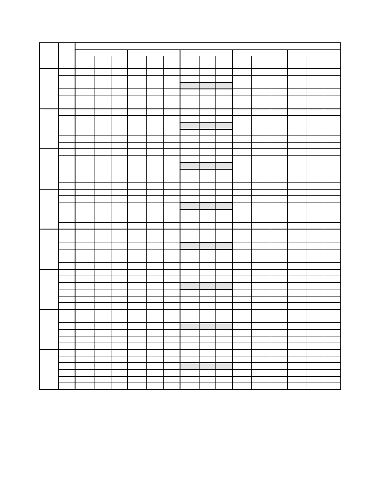
Table 7, WHR 130EW - WHR 210EW, 60 Hz, IP Units
Entering Condenser Water Temperature (10°F Delta T.)
WHR
LWT
SIZE
130EW
145EW
155EW
165EW
175EW
185EW
195EW
210EW
Notes:
1. Bold box areas certified in accordance with ARI Standard 550/590-98.
2. Ratings based on HCFC-22, evaporator fouling of 0.0001, 2.4 gpm/ton; condenser fouling of 0.00025, 3 gpm/ton.
3. For 208V units multiply capacity and EER by 0.98
4. Ratings are based on circuit #1 in lead position and circuit #2 in lag position.
5. Interpolation is allowed; extrapolation is not permitted. Consult McQuay for performance outside the ratings shown.
6. For LWT of 40°F and below please refer to Application Adjustment Factors section.
°F
40.0 133.2 98.4 16.0 126.2 109.7 13.6 122.7 115.5 12.6 115.9 126.5 10.9 108.8 137.5 9.4
42.0 137.9 98.9 16.5 130.9 110.4 14.1 127.2 116.2 13.0 120.3 127.6 11.1 113.0 138.9 9.6
44.0 143.0 99.1 17.1 135.7 111.0 14.5
46.0 148.0 99.5 17.7 140.4 111.5 14.9 136.8 117.7 13.8 129.2 129.8 11.9 121.7 141.7 10.2
48.0 153.3 99.7 18.2 145.5 112.1 15.3 142.5 118.2 14.5 133.7 130.8 12.1 127.4 142.2 10.5
50.0 158.4 99.8 18.8 150.5 112.6 15.8 146.3 119.0 14.7 138.4 131.7 12.5 130.7 143.3 10.9
40.0 145.3 101.8 17.0 137.7 113.6 14.4 133.8 119.5 13.3 126.4 130.9 11.5 118.7 142.3 9.9
42.0 150.5 102.3 17.5 142.8 114.3 14.9 138.8 120.3 13.8 131.2 132.1 11.8 123.3 143.7 10.2
44.0 156.0 102.6 18.1 148.0 114.9 15.3
46.0 161.4 102.9 18.7 153.2 115.4 15.8 149.2 121.8 14.6 141.0 134.3 12.6 132.8 146.7 10.8
48.0 167.2 103.2 19.3 158.7 116.0 16.3 155.4 122.3 15.3 145.9 135.4 12.9 139.0 147.2 11.1
50.0 172.8 103.3 20.0 164.2 116.5 16.8 159.6 123.2 15.5 151.0 136.4 13.2 142.6 148.3 11.5
40.0 151.9 109.9 16.4 143.9 122.6 13.9 139.9 129.0 12.9 132.1 141.3 11.1 124.1 153.6 9.6
42.0 157.3 110.4 16.9 149.3 123.4 14.4 145.1 129.8 13.3 137.1 142.6 11.4 128.8 155.1 9.9
44.0 163.0 110.7 17.5 154.7 124.0 14.8
46.0 168.7 111.1 18.1 160.1 124.6 15.3 155.9 131.5 14.1 147.3 144.9 12.1 138.8 158.3 10.4
48.0 174.7 111.4 18.6 165.9 125.2 15.7 162.5 132.0 14.8 152.5 146.1 12.4 145.2 158.9 10.8
50.0 180.6 111.5 19.2 171.6 125.7 16.2 166.8 132.9 15.0 157.8 147.2 12.7 149.0 160.1 11.1
40.0 164.5 118.8 16.5 155.8 132.5 14.0 151.5 139.5 13.0 143.1 152.7 11.2 134.4 166.0 9.7
42.0 170.3 119.4 17.0 161.7 133.4 14.5 157.1 140.3 13.4 148.5 154.2 11.5 139.5 167.7 9.9
44.0 176.5 119.7 17.6 167.6 134.1 14.9
46.0 182.7 120.1 18.2 173.4 134.7 15.4 168.9 142.1 14.2 159.6 156.7 12.2 150.3 171.1 10.5
48.0 189.2 120.4 18.8 179.6 135.4 15.8 176.0 142.7 14.9 165.1 158.0 12.5 157.3 171.8 10.8
50.0 195.6 120.5 19.4 185.8 135.9 16.3 180.6 143.7 15.1 171.0 159.1 12.8 161.4 173.1 11.2
40.0 178.6 130.3 16.3 169.2 145.3 13.8 164.5 152.9 12.8 155.4 167.4 11.0 145.9 182.0 9.5
42.0 185.0 130.9 16.7 175.6 146.2 14.3 170.6 153.8 13.2 161.2 169.0 11.3 151.5 183.9 9.8
44.0 191.7 131.2 17.3 182.0 147.0 14.7
46.0 198.4 131.7 18.0 188.3 147.6 15.2 183.4 155.8 14.0 173.3 171.8 12.0 163.2 187.6 10.3
48.0 205.5 132.0 18.5 195.1 148.4 15.6 191.1 156.4 14.7 179.3 173.2 12.3 170.8 188.3 10.7
50.0 212.4 132.1 19.1 201.8 149.0 16.0 196.1 157.5 14.9 185.6 174.4 12.6 175.2 189.8 11.0
40.0 186.7 130.4 17.0 176.9 145.4 14.4 172.0 153.0 13.3 162.4 167.6 11.5 152.5 182.1 9.9
42.0 193.3 131.0 17.5 183.5 146.3 14.9 178.3 153.9 13.8 168.5 169.1 11.8 158.4 184.0 10.2
44.0 200.4 131.3 18.1 190.2 147.1 15.3
46.0 207.4 131.8 18.7 196.8 147.7 15.8 191.7 155.9 14.6 181.1 171.9 12.6 170.6 187.7 10.8
48.0 214.8 132.1 19.3 203.9 148.5 16.3 199.7 156.6 15.3 187.4 173.3 12.9 178.5 188.4 11.1
50.0 222.0 132.2 20.0 210.9 149.1 16.8 205.0 157.6 15.5 194.0 174.5 13.2 183.2 189.9 11.5
40.0 198.8 141.4 16.7 188.3 157.7 14.2 183.1 165.9 13.2 173.0 181.7 11.3 162.4 197.5 9.8
42.0 205.9 142.0 17.2 195.4 158.7 14.7 189.9 166.9 13.6 179.5 183.4 11.6 168.6 199.5 10.1
44.0 213.4 142.4 17.9 202.5 159.5 15.1
46.0 220.8 142.9 18.5 209.6 160.2 15.6 204.1 169.1 14.4 192.9 186.4 12.4 181.6 203.6 10.6
48.0 228.7 143.2 19.0 217.1 161.0 16.0 212.7 169.8 15.1 199.6 187.9 12.7 190.1 204.3 11.0
50.0 236.4 143.4 19.7 224.6 161.7 16.5 218.3 171.0 15.3 206.6 189.3 13.0 195.0 205.9 11.3
40.0 212.9 150.7 16.8 201.7 168.1 14.3 196.1 176.9 13.3 185.3 193.7 11.4 174.0 210.6 9.9
42.0 220.5 151.4 17.3 209.3 169.2 14.8 203.4 177.9 13.7 192.2 195.5 11.7 180.6 212.7 10.2
44.0 228.5 151.8 18.0 216.9 170.1 15.2
46.0 236.5 152.3 18.6 224.5 170.8 15.7 218.6 180.3 14.5 206.6 198.7 12.5 194.5 217.0 10.7
48.0 245.0 152.7 19.2 232.5 171.7 16.1 227.8 181.0 15.2 213.7 200.3 12.8 203.6 217.8 11.1
50.0 253.2 152.9 19.8 240.5 172.4 16.6 233.8 182.2 15.4 221.3 201.8 13.1 208.9 219.5 11.4
70°F 80°F 85°F 95°F 105°F
Cap. PWR Cap. PWR Cap. PWR Cap. PWR Cap. PWR
Tons kWi
EER
Tons kWi
EER
Tons kWi
132.0 117.0 13.4
144.0 121.1 14.2
150.5 130.7 13.7
163.0 141.3 13.8
177.0 154.9 13.6
185.0 155.0 14.2
197.0 168.1 14.0
211.0 179.2 14.1
EER
Tons kWi
124.6 128.8 11.5 116.8 140.2 9.9
135.9 133.3 12.1 127.4 145.1 10.5
142.1 143.9 11.7 133.2 156.6 10.1
153.9 155.6 11.8 144.3 169.3 10.2
167.1 170.5 11.6 156.6 185.6 10.1
174.6 170.7 12.1 163.7 185.8 10.5
186.0 185.1 12.0 174.3 201.5 10.4
199.2 197.3 12.1 186.7 214.8 10.4
EER
Tons kWi
EER
Product Manual WHR-2 21
Page 22
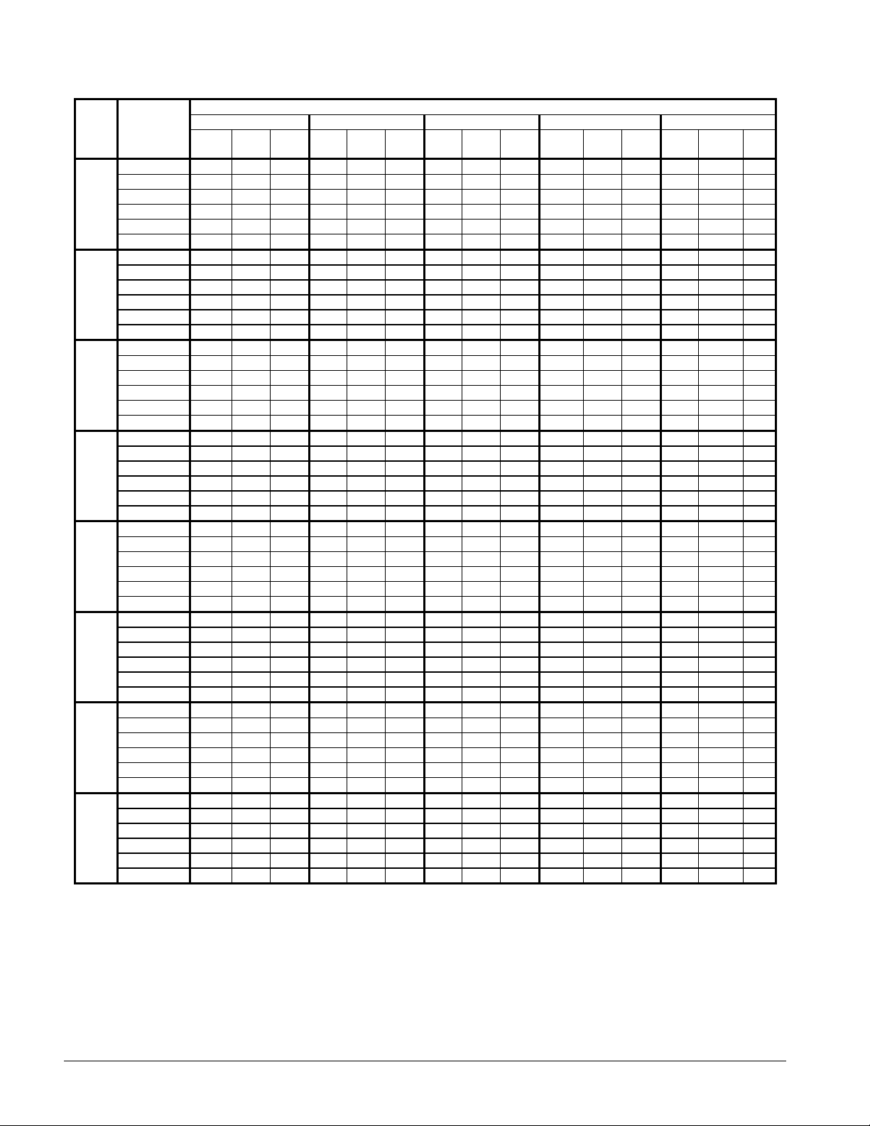
Table 8, WHR 017EW - WHR 060EW, 60 Hz, SI Units
Entering Condenser Water Temperature (°C)
WHR
SIZE
017EW
020EW
025EW
030EW
040EW
045EW
050EW
060EW
Notes:
1. Ratings based on HCFC-22, evaporator fouling of 0.0176, 0.043 L/s; condenser fouling of 0.044.
2. For 208V units multiply capacity and COP by 0.98.
3. Ratings are based on circuit #1 in lead position and circuit #2 in lag position.
4. Interpolation is allowed; extrapolation is not permitted. Consult McQuay for performance outside the ratings shown.
5. For LWT of 5°C and below please refer to Application Adjustment Factors section.
LWT
°C
5.0 (41.0°F) 64.5 11.4 5.1 61.7 12.7 4.5 58.5 13.9 3.9 54.7 15.0 3.4 52.8 16.3 2.9
6.0 (42.8°F) 66.8 11.5 5.3 63.6 12.8 4.7 60.8 14.1 4.1 56.8 15.2 3.4 54.3 16.5 3.0
7.0 (44.6°F) 69.1 11.6 5.5 65.3 12.8 4.8 63.1 14.1 4.1 58.8 15.3 3.6 56.5 16.7 3.1
8.0 (46.4°F) 70.2 11.6 5.5 67.0 12.9 4.8 64.0 14.2 4.2 60.8 15.5 3.7 57.6 16.7 3.2
9.0 (48.2°F) 72.8 11.6 5.8 69.4 12.9 5.0 67.7 14.3 4.4 63.1 15.6 3.8 59.7 16.9 3.2
10.0 (50.0°F) 75.1 11.7 6.0 72.0 13.0 5.1 68.5 14.4 4.4 65.4 15.8 3.9 61.9 17.1 3.4
5.0 (41.0°F) 79.1 15.2 4.9 75.6 16.8 4.3 71.7 18.4 3.7 67.1 19.9 3.2 64.7 21.5 2.8
6.0 (42.8°F) 81.9 15.3 5.0 78.0 16.9 4.4 74.5 18.6 3.8 69.6 20.1 3.3 66.6 21.8 2.9
7.0 (44.6°F) 84.7 15.3 5.2 80.1 17.0 4.5 77.3 18.7 3.9 72.1 20.3 3.4 69.3 22.1 3.0
8.0 (46.4°F) 86.1 15.3 5.3 82.2 17.0 4.6 78.4 18.8 4.0 74.5 20.5 3.5 70.6 22.2 3.0
9.0 (48.2°F) 89.2 15.4 5.5 85.1 17.1 4.7 83.0 18.9 4.1 77.4 20.7 3.6 73.1 22.4 3.1
10.0 (50.0°F) 92.1 15.4 5.7 88.3 17.2 4.9 84.0 19.0 4.2 80.2 20.9 3.7 75.9 22.6 3.2
5.0 (41.0°F) 98.4 19.2 4.8 94.1 21.3 4.1 89.2 23.3 3.6 83.5 25.1 3.1 80.5 27.3 2.7
6.0 (42.8°F) 101.9 19.3 4.9 97.1 21.4 4.3 92.7 23.6 3.7 86.6 25.4 3.2 82.8 27.7 2.8
7.0 (44.6°F) 105.4 19.4 5.1 99.7 21.5 4.4 96.2 23.7 3.8 89.7 25.7 3.3 86.2 28.0 2.9
8.0 (46.4°F) 107.2 19.4 5.1 102.3 21.6 4.5 97.6 23.8 3.9 92.7 25.9 3.4 87.8 28.1 3.0
9.0 (48.2°F) 111.0 19.5 5.3 105.9 21.7 4.6 103.3 24.0 4.0 96.3 26.2 3.5 91.0 28.3 3.0
10.0 (50.0°F) 114.5 19.6 5.6 109.9 21.8 4.8 104.6 24.1 4.1 99.8 26.5 3.6 94.4 28.6 3.1
5.0 (41.0°F) 110.0 21.2 4.9 105.2 23.6 4.3 99.8 25.8 3.7 93.4 27.8 3.2 90.1 30.2 2.8
6.0 (42.8°F) 113.9 21.4 5.0 108.6 23.7 4.4 103.7 26.1 3.8 96.9 28.1 3.3 92.6 30.6 2.9
7.0 (44.6°F) 117.8 21.5 5.2 111.5 23.8 4.5 107.6 26.2 3.9 100.3 28.4 3.4 96.4 31.0 3.0
8.0 (46.4°F) 119.9 21.5 5.3 114.4 23.9 4.6 109.1 26.4 4.0 103.7 28.7 3.5 98.2 31.1 3.0
9.0 (48.2°F) 124.2 21.5 5.5 118.4 24.0 4.7 115.5 26.5 4.1 107.7 29.0 3.6 101.8 31.4 3.1
10.0 (50.0°F) 128.1 21.7 5.7 122.9 24.2 4.9 117.0 26.7 4.2 111.6 29.3 3.7 105.6 31.7 3.2
5.0 (41.0°F) 140.1 26.4 5.1 134.7 28.8 4.4 127.7 31.1 4.0 119.8 34.1 3.3 112.9 36.6 3.0
6.0 (42.8°F) 145.4 26.5 5.3 138.3 29.0 4.6 131.1 31.9 4.0 124.2 34.5 3.5 117.3 37.0 3.1
7.0 (44.6°F) 150.4 26.7 5.4 143.0 29.0 4.7 136.0 32.1 4.1 128.8 34.9 3.6 121.7 37.5 3.2
8.0 (46.4°F) 152.9 26.8 5.5 145.9 29.1 4.8 138.5 32.3 4.2 131.3 35.0 3.7 123.7 37.7 3.2
9.0 (48.2°F) 158.4 26.9 5.7 150.8 29.3 4.9 143.3 32.6 4.3 136.0 35.4 3.7 128.3 38.2 3.3
10.0 (50.0°F) 163.7 27.1 5.9 156.2 29.5 5.1 148.4 32.9 4.4 140.7 35.8 3.8 133.0 38.6 3.3
5.0 (41.0°F) 162.2 29.9 5.2 156.0 32.7 4.5 147.9 35.4 4.1 138.7 38.7 3.4 130.7 41.5 3.1
6.0 (42.8°F) 168.3 30.0 5.4 160.1 32.9 4.7 151.8 36.2 4.1 143.8 39.2 3.6 135.8 42.0 3.1
7.0 (44.6°F) 174.2 30.3 5.5 165.6 33.0 4.8 157.5 36.5 4.2 149.1 39.6 3.7 140.9 42.6 3.2
8.0 (46.4°F) 177.1 30.4 5.7 168.9 33.1 4.9 160.4 36.7 4.2 152.0 39.8 3.7 143.3 42.8 3.3
9.0 (48.2°F) 183.4 30.6 5.9 174.6 33.3 5.0 165.9 37.0 4.4 157.5 40.2 3.8 148.6 43.4 3.3
10.0 (50.0°F) 189.6 30.7 6.1 180.8 33.5 5.2 171.8 37.4 4.5 162.9 40.6 3.9 154.0 43.9 3.4
5.0 (41.0°F) 189.8 37.5 4.9 182.6 41.0 4.2 173.1 44.3 3.8 162.3 48.5 3.2 153.0 52.0 2.9
6.0 (42.8°F) 197.0 37.6 5.1 187.4 41.2 4.4 177.7 45.3 3.9 168.3 49.1 3.4 158.9 52.7 3.0
7.0 (44.6°F) 203.9 38.0 5.2 193.9 41.3 4.5 184.4 45.7 3.9 174.6 49.6 3.4 164.9 53.3 3.0
8.0 (46.4°F) 207.3 38.1 5.3 197.7 41.5 4.6 187.7 45.9 4.0 177.9 49.9 3.5 167.7 53.7 3.1
9.0 (48.2°F) 214.7 38.3 5.5 204.4 41.7 4.7 194.2 46.4 4.1 184.4 50.4 3.6 173.9 54.3 3.1
10.0 (50.0°F) 221.9 38.5 5.7 211.6 42.0 4.9 201.1 46.8 4.2 190.7 50.9 3.7 180.3 54.9 3.2
5.0 (41.0°F) 215.6 40.7 5.1 207.4 44.5 4.4 196.7 48.1 4.0 184.4 52.7 3.3 173.8 56.5 3.0
6.0 (42.8°F) 223.8 40.9 5.3 212.9 44.8 4.6 201.9 49.2 4.1 191.1 53.3 3.5 180.5 57.2 3.1
7.0 (44.6°F) 231.6 41.3 5.4 220.2 44.9 4.7 209.4 49.7 4.1 198.3 53.9 3.6 187.3 57.9 3.2
8.0 (46.4°F) 235.4 41.4 5.6 224.6 45.0 4.8 213.2 49.9 4.2 202.1 54.2 3.7 190.5 58.3 3.2
9.0 (48.2°F) 243.9 41.6 5.8 232.1 45.3 4.9 220.6 50.4 4.3 209.4 54.7 3.7 197.5 59.0 3.3
10.0 (50.0°F) 252.1 41.8 5.9 240.4 45.6 5.1 228.4 50.9 4.4 216.6 55.3 3.9 204.8 59.7 3.3
20°C (68°F) 25°C (77°F) 30°C (86°F) 35°C (95°F) 40°C (104°F)
Cap. PWR Cap. PWR Cap. PWR Cap. PWR Cap. PWR
kW kWi
COP
kW kWi
COP
kW kWi
COP
kW kWi
COP
kW kWi
COP
22 Product Manual WHR-2
Page 23

Table 9, WHR 070EW - WHR 120EW, 60 Hz, SI Units
WHR
SIZE
070EW 7.0 (44.6°F) 279.1 52.6 5.2 265.4 57.2 4.5 252.4 63.3 3.9 239.0 68.6 3.4 225.7 73.8 3.0
080EW 7.0 (44.6°F) 302.9 57.2 5.2 288.0 62.2 4.5 273.9 68.9 3.9 259.3 74.7 3.4 244.9 80.3 3.0
085EW 7.0 (44.6°F) 336.5 61.2 5.4 320.0 66.5 4.6 304.3 73.6 4.0 288.1 79.8 3.5 272.2 85.8 3.1
090EW 7.0 (44.6°F) 362.2 64.4 5.5 344.4 70.0 4.8 327.6 77.5 4.1 310.1 84.0 3.6 293.0 90.3 3.2
095EW 7.0 (44.6°F) 375.7 67.3 5.5 358.6 74.8 4.7 341.7 82.4 4.1 324.4 89.8 3.6 307.7 97.1 3.1
100EW 7.0 (44.6°F) 399.2 71.6 5.5 381.0 79.5 4.7 363.0 87.6 4.1 344.7 95.4 3.6 326.9 103.2 3.1
110EW 7.0 (44.6°F) 436.4 79.4 5.4 416.5 88.2 4.6 396.8 97.2 4.0 376.8 105.9 3.5 357.4 114.6 3.1
115EW 7.0 (44.6°F) 444.2 79.5 5.5 424.0 88.3 4.7 403.9 97.3 4.1 383.5 106.0 3.6 363.8 114.7 3.2
120EW 7.0 (44.6°F) 477.5 87.2 5.4 455.7 96.9 4.6 434.2 106.7 4.0 412.2 116.3 3.5 391.0 125.8 3.1
Notes:
1. Ratings based on HCFC-22, evaporator fouling of 0.0176, 0.043 L/s; condenser fouling of 0.044.
2. For 208V units multiply capacity and COP by 0.98
3. Ratings are based on circuit #1 in lead position and circuit #2 in lag position.
4. Interpolation is allowed; extrapolation is not permitted. Consult McQuay for performance outside the ratings shown.
5. For LWT of 5°C and below please refer to Application Adjustment Factors section.
LWT
°C
5.0 (41.0°F) 259.8 51.9 4.9 249.9 56.7 4.2 237.0 61.3 3.8 222.2 67.1 3.2 209.5 72.0 2.9
6.0 (42.8°F) 269.7 52.1 5.1 256.6 57.0 4.4 243.3 62.7 3.8 230.3 67.9 3.3 217.6 72.9 2.9
8.0 (46.4°F) 283.7 52.7 5.3 270.7 57.4 4.5 257.0 63.6 4.0 243.5 69.0 3.5 229.6 74.3 3.0
9.0 (48.2°F) 293.9 53.0 5.5 279.8 57.7 4.7 265.8 64.2 4.1 252.4 69.7 3.6 238.0 75.2 3.1
10.0 (50.0°F) 303.8 53.3 5.6 289.7 58.1 4.8 275.3 64.8 4.2 261.0 70.4 3.7 246.8 76.0 3.2
5.0 (41.0°F) 282.0 56.4 4.9 271.2 61.7 4.2 257.2 66.7 3.8 241.1 73.0 3.1 227.3 78.4 2.8
6.0 (42.8°F) 292.7 56.7 5.1 278.4 62.0 4.4 264.0 68.2 3.8 250.0 73.9 3.3 236.1 79.3 2.9
8.0 (46.4°F) 307.9 57.4 5.3 293.7 62.4 4.5 278.8 69.2 4.0 264.3 75.1 3.5 249.1 80.8 3.0
9.0 (48.2°F) 318.9 57.7 5.5 303.6 62.8 4.7 288.5 69.8 4.1 273.9 75.8 3.5 258.3 81.8 3.1
10.0 (50.0°F) 329.6 58.0 5.6 314.4 63.2 4.8 298.7 70.5 4.2 283.2 76.6 3.7 267.8 82.7 3.1
5.0 (41.0°F) 313.3 60.4 5.1 301.3 65.9 4.4 285.7 71.3 3.9 267.9 78.0 3.3 252.5 83.8 3.0
6.0 (42.8°F) 325.2 60.6 5.3 309.3 66.3 4.6 293.3 73.0 4.0 277.7 79.0 3.5 262.3 84.8 3.0
8.0 (46.4°F) 342.1 61.3 5.5 326.3 66.7 4.7 309.8 73.9 4.1 293.6 80.3 3.6 276.8 86.4 3.2
9.0 (48.2°F) 354.3 61.7 5.7 337.3 67.2 4.9 320.5 74.6 4.3 304.3 81.1 3.7 287.0 87.5 3.2
10.0 (50.0°F) 366.2 62.0 5.9 349.3 67.6 5.0 331.9 75.3 4.3 314.7 81.9 3.8 297.5 88.4 3.3
5.0 (41.0°F) 337.2 63.5 5.2 324.4 69.4 4.5 307.6 75.1 4.0 288.4 82.1 3.3 271.9 88.2 3.0
6.0 (42.8°F) 350.1 63.8 5.4 333.0 69.8 4.7 315.7 76.8 4.1 299.0 83.2 3.5 282.4 89.2 3.1
8.0 (46.4°F) 368.2 64.5 5.6 351.3 70.2 4.8 333.5 77.8 4.2 316.1 84.5 3.7 297.9 90.9 3.2
9.0 (48.2°F) 381.4 64.9 5.8 363.1 70.7 5.0 345.0 78.6 4.4 327.6 85.3 3.8 309.0 92.0 3.3
10.0 (50.0°F) 394.3 65.2 6.0 376.0 71.1 5.1 357.3 79.3 4.4 338.8 86.2 3.9 320.3 93.1 3.3
5.0 (41.0°F) 350.2 66.9 5.1 334.0 74.2 4.4 317.8 81.3 3.9 301.8 88.3 3.3 285.5 95.1 3.0
6.0 (42.8°F) 363.0 67.2 5.3 346.0 74.5 4.6 329.8 81.8 3.9 312.8 89.1 3.5 296.3 96.2 3.1
8.0 (46.4°F) 382.3 67.4 5.6 365.0 75.0 4.8 347.8 82.6 4.1 330.4 90.2 3.6 313.2 97.6 3.2
9.0 (48.2°F) 395.7 67.5 5.8 377.1 75.2 4.9 362.4 83.1 4.3 342.1 90.9 3.7 324.7 98.5 3.2
10.0 (50.0°F) 409.2 67.6 6.0 390.9 75.6 5.1 372.7 83.5 4.4 354.0 91.5 3.8 336.1 99.4 3.3
5.0 (41.0°F) 372.1 71.1 5.1 354.8 78.9 4.4 337.7 86.4 3.9 320.7 93.9 3.3 303.4 101.1 3.0
6.0 (42.8°F) 385.7 71.4 5.3 367.7 79.2 4.6 350.4 87.0 3.9 332.4 94.7 3.5 314.8 102.2 3.1
8.0 (46.4°F) 406.2 71.6 5.6 387.8 79.7 4.8 369.6 87.8 4.1 351.0 95.8 3.6 332.7 103.7 3.2
9.0 (48.2°F) 420.4 71.7 5.8 400.6 80.0 4.9 385.1 88.3 4.3 363.5 96.6 3.7 345.0 104.7 3.2
10.0 (50.0°F) 434.7 71.8 6.0 415.3 80.4 5.1 396.0 88.8 4.4 376.1 97.3 3.8 357.1 105.7 3.3
5.0 (41.0°F) 406.8 78.9 5.1 387.9 87.5 4.4 369.1 95.9 3.9 350.6 104.2 3.3 331.6 112.2 2.9
6.0 (42.8°F) 421.6 79.3 5.2 401.9 87.9 4.5 383.0 96.5 3.9 363.3 105.1 3.4 344.1 113.5 3.0
8.0 (46.4°F) 444.1 79.5 5.5 423.9 88.4 4.7 404.0 97.5 4.1 383.7 106.4 3.6 363.7 115.1 3.1
9.0 (48.2°F) 459.6 79.6 5.7 437.9 88.8 4.9 421.0 98.0 4.2 397.3 107.2 3.7 377.1 116.2 3.2
10.0 (50.0°F) 475.2 79.7 5.9 454.0 89.2 5.0 432.9 98.5 4.3 411.2 108.0 3.8 390.4 117.3 3.3
5.0 (41.0°F) 414.1 79.0 5.2 394.9 87.6 4.5 375.7 96.0 3.9 356.8 104.3 3.3 337.6 112.3 3.0
6.0 (42.8°F) 429.2 79.3 5.3 409.1 88.0 4.6 389.9 96.6 4.0 369.9 105.2 3.5 350.3 113.6 3.1
8.0 (46.4°F) 452.0 79.6 5.6 431.5 88.5 4.8 411.2 97.6 4.2 390.6 106.5 3.7 370.2 115.2 3.2
9.0 (48.2°F) 467.8 79.7 5.8 445.8 88.9 5.0 428.5 98.2 4.3 404.4 107.3 3.7 383.8 116.3 3.2
10.0 (50.0°F) 483.7 79.8 6.0 462.2 89.3 5.1 440.6 98.6 4.4 418.5 108.1 3.8 397.4 117.4 3.3
5.0 (41.0°F) 445.1 86.7 5.1 424.4 96.1 4.4 403.9 105.3 3.8 383.6 114.4 3.3 362.8 123.2 2.9
6.0 (42.8°F) 461.3 87.0 5.2 439.8 96.5 4.5 419.1 106.0 3.9 397.6 115.4 3.4 376.6 124.6 3.0
8.0 (46.4°F) 485.9 87.3 5.5 463.8 97.1 4.7 442.0 107.0 4.1 419.8 116.8 3.6 398.0 126.4 3.1
9.0 (48.2°F) 502.8 87.4 5.7 479.2 97.5 4.9 460.6 107.7 4.2 434.7 117.7 3.7 412.6 127.6 3.2
10.0 (50.0°F) 520.0 87.5 5.9 496.8 97.9 5.0 473.6 108.2 4.3 449.9 118.6 3.8 427.2 128.8 3.3
20°C (68°F) 25°C (77°F) 30°C (86°F) 35°C (95°F) 40°C (104°F)
Cap. PWR Cap. PWR Cap. PWR Cap. PWR Cap. PWR
kW kWi
COP
kW kWi
Entering Condenser Water Temperature (°C)
COP
kW kWi
COP
kW kWi
COP
kW kWi
COP
Product Manual WHR-2 23
Page 24
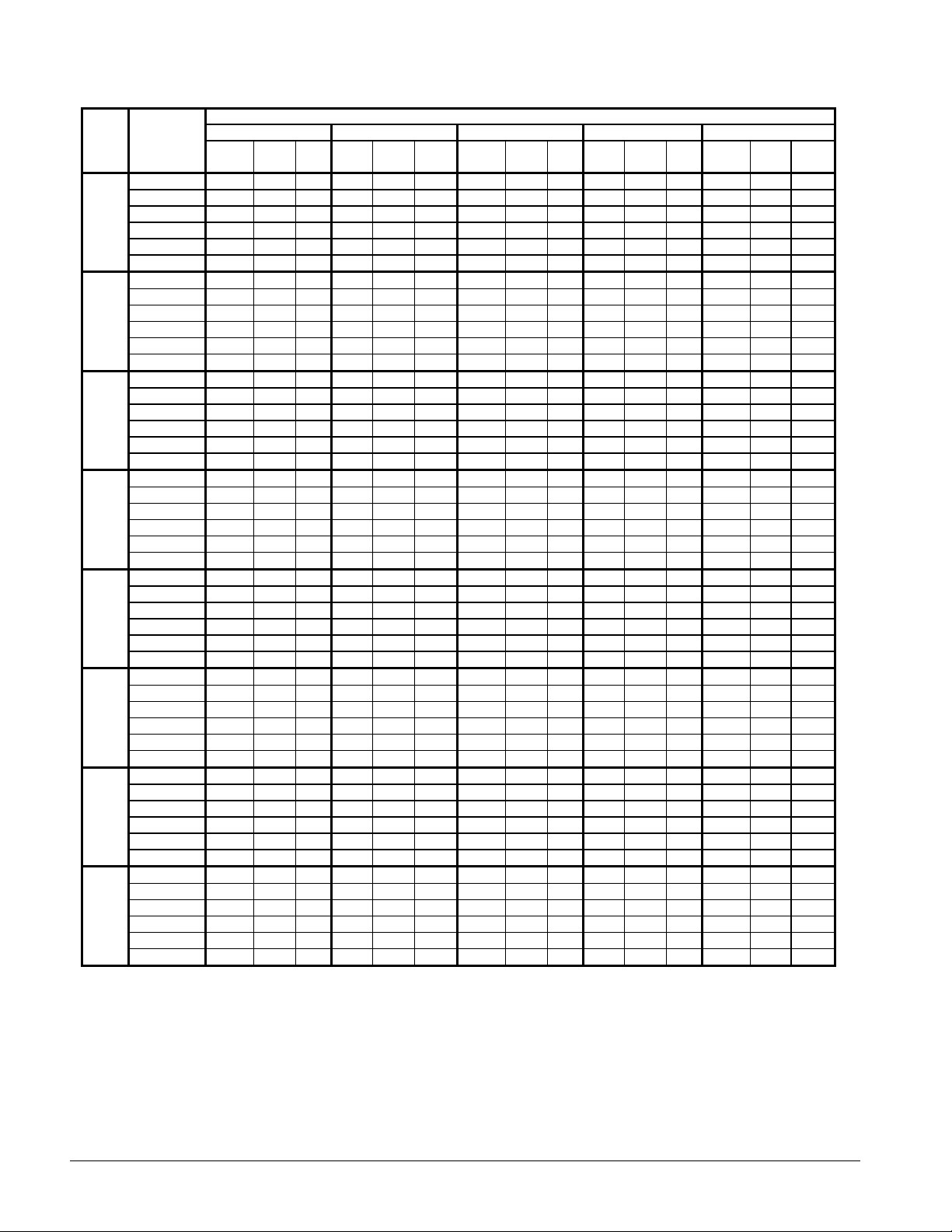
Table 10, WHR 130EW - WHR 210EW, 60 Hz, SI Units
Entering Condenser Water Temperature (°C)
WHR
SIZE
130EW
145EW
155EW
165EW
175EW
185EW
195EW
210EW
Notes:
1. Ratings based on HCFC-22 evaporator fouling of 0.0176, 0.043 L/s; condenser fouling of 0.044.
2. For 208V units multiply capacity and COP by 0.98.
3. Ratings are based on circuit #1 in lead position and circuit #2 in lag position.
4. Interpolation is allowed; extrapolation is not permitted. Consult McQuay for performance outside the ratings shown.
5. For LWT of 5°C and below please refer to Application Adjustment Factors section.
LWT
°C
5.0 (41.0°F) 481.6 96.3 4.9 459.2 106.8 4.3 437.0 117.0 3.7 415.0 127.1 3.2 392.6 136.9 2.9
6.0 (42.8°F) 499.1 96.7 5.1 475.8 107.2 4.4 453.4 117.8 3.8 430.2 128.2 3.3 407.4 138.5 2.9
7.0 (44.6°F) 516.6 96.9 5.3 493.1 107.6 4.5 469.8 118.6 3.9 446.0 129.2 3.4 423.1 139.8 3.0
8.0 (46.4°F) 525.7 97.0 5.3 501.9 107.9 4.6 478.2 118.9 4.0 454.2 129.8 3.5 430.6 140.4 3.0
9.0 (48.2°F) 544.1 97.1 5.5 518.4 108.3 4.7 498.3 119.6 4.1 470.4 130.8 3.6 446.4 141.8 3.1
10.0 (50.0°F) 562.6 97.2 5.8 537.5 108.8 4.8 512.5 120.2 4.2 486.8 131.7 3.7 462.2 143.1 3.2
5.0 (41.0°F) 525.3 99.7 5.2 501.0 110.5 4.5 476.7 121.1 3.9 452.7 131.6 3.4 428.3 141.7 3.0
6.0 (42.8°F) 544.5 100.1 5.3 519.1 111.0 4.6 494.6 121.9 4.0 469.3 132.7 3.5 444.5 143.3 3.1
7.0 (44.6°F) 563.6 100.3 5.6 537.9 111.4 4.7 512.5 122.7 4.1 486.6 133.8 3.6 461.6 144.7 3.2
8.0 (46.4°F) 573.5 100.4 5.6 547.5 111.7 4.8 521.7 123.1 4.2 495.5 134.3 3.7 469.7 145.4 3.2
9.0 (48.2°F) 593.5 100.5 5.8 565.6 112.1 5.0 543.6 123.8 4.3 513.1 135.4 3.8 487.0 146.7 3.3
10.0 (50.0°F) 613.7 100.6 6.1 586.3 112.6 5.1 559.0 124.4 4.4 531.0 136.4 3.9 504.2 148.1 3.4
5.0 (41.0°F) 549.0 107.6 5.0 523.6 119.3 4.4 498.2 130.7 3.8 473.2 142.0 3.3 447.6 152.9 2.9
6.0 (42.8°F) 569.1 108.0 5.2 542.5 119.8 4.5 517.0 131.6 3.9 490.4 143.2 3.4 464.5 154.7 3.0
7.0 (44.6°F) 589.1 108.2 5.4 562.2 120.2 4.6 535.6 132.5 4.0 508.5 144.4 3.5 482.4 156.1 3.1
8.0 (46.4°F) 599.4 108.3 5.4 572.2 120.5 4.7 545.3 132.8 4.1 517.9 145.0 3.6 490.9 156.9 3.1
9.0 (48.2°F) 620.3 108.5 5.6 591.1 121.0 4.8 568.2 133.6 4.2 536.3 146.1 3.6 509.0 158.4 3.2
10.0 (50.0°F) 641.4 108.6 5.9 612.8 121.6 5.0 584.3 134.3 4.3 555.0 147.2 3.8 527.0 159.8 3.3
5.0 (41.0°F) 594.6 116.3 5.0 567.1 129.0 4.4 539.6 141.3 3.8 512.5 153.5 3.3 484.8 165.3 2.9
6.0 (42.8°F) 616.3 116.8 5.2 587.6 129.5 4.5 559.9 142.2 3.9 531.2 154.8 3.4 503.1 167.2 3.0
7.0 (44.6°F) 638.0 117.0 5.4 608.9 130.0 4.6 580.1 143.2 4.0 550.8 156.1 3.5 522.5 168.8 3.1
8.0 (46.4°F) 649.2 117.1 5.5 619.7 130.3 4.7 590.6 143.6 4.1 560.9 156.7 3.6 531.7 169.6 3.1
9.0 (48.2°F) 671.8 117.3 5.6 640.2 130.8 4.8 615.4 144.5 4.2 580.8 158.0 3.6 551.2 171.2 3.2
10.0 (50.0°F) 694.7 117.4 5.9 663.7 131.4 5.0 632.8 145.2 4.3 601.1 159.1 3.8 570.7 172.8 3.3
5.0 (41.0°F) 645.7 127.5 5.0 615.8 141.4 4.3 585.9 154.8 3.8 556.5 168.3 3.2 526.4 181.2 2.9
6.0 (42.8°F) 669.3 128.0 5.1 638.0 142.0 4.5 608.0 155.9 3.8 576.8 169.7 3.4 546.3 183.3 3.0
7.0 (44.6°F) 692.8 128.3 5.4 661.2 142.5 4.5 629.9 157.0 3.9 598.1 171.1 3.5 567.3 185.1 3.1
8.0 (46.4°F) 704.9 128.4 5.4 672.9 142.8 4.6 641.3 157.4 4.0 609.1 171.8 3.5 577.4 185.9 3.1
9.0 (48.2°F) 729.5 128.5 5.6 695.2 143.4 4.8 668.2 158.4 4.2 630.7 173.2 3.6 598.6 187.7 3.1
10.0 (50.0°F) 754.4 128.7 5.8 720.7 144.1 4.9 687.2 159.2 4.2 652.7 174.4 3.7 619.7 189.4 3.2
5.0 (41.0°F) 674.9 127.6 5.2 643.6 141.5 4.5 612.4 154.9 4.0 581.6 168.4 3.4 550.2 181.3 3.0
6.0 (42.8°F) 699.5 128.1 5.4 666.9 142.1 4.7 635.5 156.0 4.0 602.9 169.8 3.5 571.0 183.4 3.1
7.0 (44.6°F) 724.1 128.4 5.6 691.1 142.6 4.7 658.4 157.1 4.1 625.1 171.2 3.6 593.0 185.2 3.2
8.0 (46.4°F) 736.8 128.5 5.6 703.4 142.9 4.8 670.3 157.5 4.2 636.6 171.9 3.7 603.5 186.0 3.2
9.0 (48.2°F) 762.5 128.6 5.8 726.6 143.5 5.0 698.4 158.5 4.4 659.2 173.3 3.8 625.6 187.8 3.3
10.0 (50.0°F) 788.5 128.8 6.1 753.3 144.2 5.1 718.2 159.3 4.4 682.2 174.5 3.9 647.8 189.5 3.4
5.0 (41.0°F) 718.7 138.4 5.1 685.3 153.4 4.4 652.1 168.0 3.9 619.4 182.7 3.3 585.9 196.7 3.0
6.0 (42.8°F) 744.9 138.9 5.3 710.1 154.1 4.6 676.7 169.2 3.9 642.0 184.2 3.5 608.0 198.9 3.1
7.0 (44.6°F) 771.1 139.2 5.5 735.9 154.6 4.7 701.1 170.4 4.1 665.6 185.7 3.6 631.4 200.8 3.1
8.0 (46.4°F) 784.6 139.3 5.5 749.0 155.0 4.7 713.7 170.8 4.1 677.9 186.4 3.6 642.6 201.8 3.2
9.0 (48.2°F) 812.0 139.5 5.7 773.7 155.6 4.9 743.7 171.9 4.3 702.0 188.0 3.7 666.2 203.7 3.2
10.0 (50.0°F) 839.6 139.7 6.0 802.1 156.3 5.0 764.8 172.7 4.4 726.5 189.3 3.8 689.8 205.6 3.3
5.0 (41.0°F) 769.8 147.5 5.1 734.0 163.5 4.5 698.5 179.1 3.9 663.4 194.7 3.3 627.5 209.6 3.0
6.0 (42.8°F) 797.8 148.1 5.3 760.6 164.2 4.6 724.8 180.4 4.0 687.6 196.3 3.5 651.3 212.1 3.1
7.0 (44.6°F) 825.9 148.4 5.5 788.2 164.9 4.7 750.9 181.6 4.1 713.0 197.9 3.6 676.3 214.1 3.1
8.0 (46.4°F) 840.3 148.5 5.6 802.2 165.3 4.8 764.5 182.1 4.1 726.1 198.8 3.6 688.3 215.1 3.2
9.0 (48.2°F) 869.7 148.7 5.8 828.7 165.9 5.0 796.6 183.2 4.3 751.9 200.4 3.7 713.6 217.1 3.2
10.0 (50.0°F) 899.3 148.9 6.0 859.2 166.7 5.1 819.2 184.1 4.4 778.1 201.8 3.8 738.8 219.1 3.3
20°C (68°F) 25°C (77°F) 30°C (86°F) 35°C (95°F) 40°C (104°F)
Cap. PWR Cap. PWR Cap. PWR Cap. PWR Cap. PWR
kW kWi
COP
kW kWi
COP
kW kWi
COP
kW kWi
COP
kW kWi
COP
24 Product Manual WHR-2
Page 25
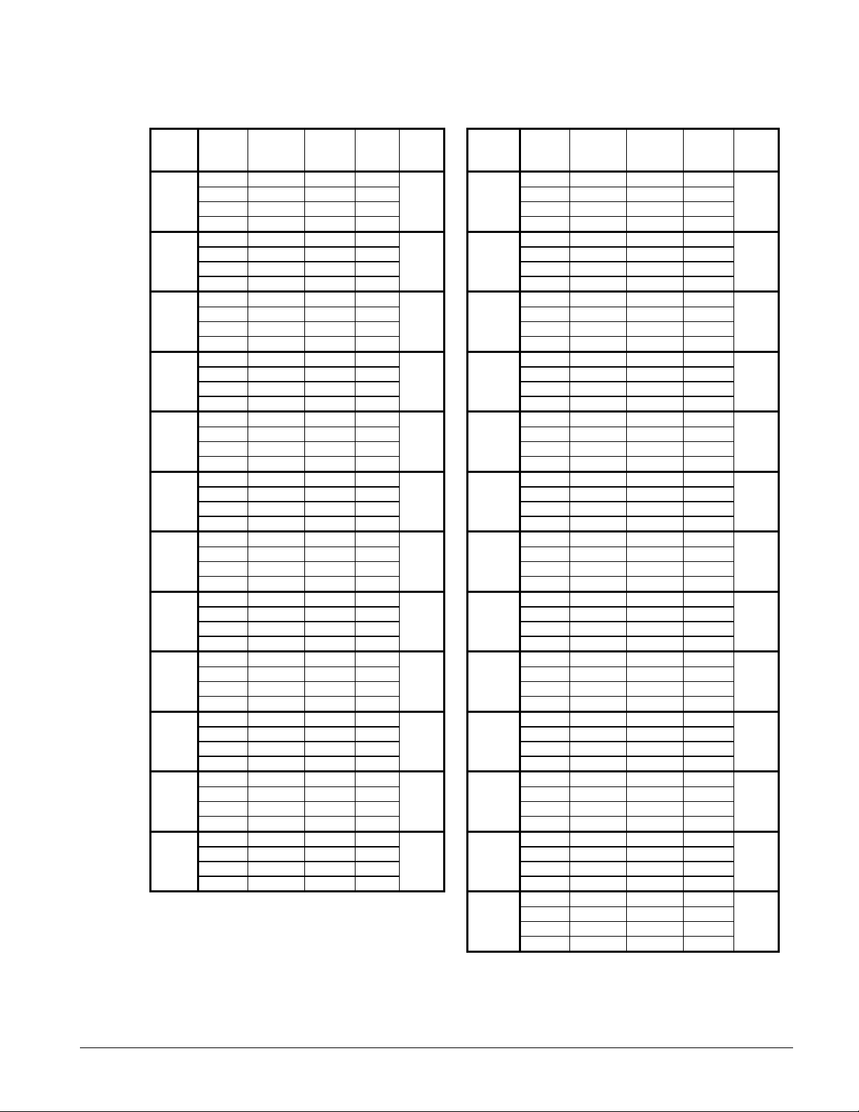
Part Load Data (EW Only)
Table 11, Part Load Performance
Unit Size % Load
100.00 17.7 14.7 14.4 100.00 96.0 82.0 14.0
017EW
020EW
025EW
030EW
040EW
045EW
050EW
060EW
070EW
080EW
085EW
090EW
Note: Part load data certified under ARI Standard 550/590-98 100.00 211.0 180.1 14.1
75.00 13.3 9.1 17.5 20.3
50.00 8.8 4.5 23.5 50.00 48.0 26.3 21.9
25.00 4.4 2.9 18.2 25.00 24.0 15.1 19.1
100.00 21.7 19.3 13.5 100.00 102.0 87.2 14.0
75.00 16.2 11.7 16.6 18.9
50.00 10.8 6.0 21.6 50.00 51.0 28.0 21.9
25.00 5.4 3.7 17.5 25.00 25.5 15.0 20.4
100.00 27.0 24.2 13.4 100.00 111.5 96.8 13.8
75.00 20.3 14.4 16.9 18.4
50.00 13.6 8.1 20.1 50.00 55.7 29.9 22.4
25.00 6.7 4.7 17.1 25.00 28.0 16.3 20.6
100.00 30.0 26.7 13.5 100.00 113.5 97.0 14.0
75.00 22.6 16.1 16.8 18.7
50.00 15.1 8.7 20.8 50.00 56.7 30.4 22.4
25.00 7.5 5.1 17.6 25.00 28.5 18.7 18.3
100.00 38.0 32.6 14.0 100.00 122.0 106.1 13.8
75.00 28.5 19.6 17.4 19.2
50.00 19.0 11.1 20.5 50.00 61.0 33.0 22.2
25.00 9.5 5.5 20.7 25.00 30.5 18.9 19.4
100.00 44.0 36.8 14.3 100.00 132.0 118.0 13.4
75.00 33.1 22.6 17.6 19.2
50.00 22.1 12.8 20.7 50.00 65.9 35.7 22.2
25.00 11.0 6.8 19.4 25.00 32.9 19.3 20.5
100.00 51.5 46.0 13.4 100.00 144.0 122.0 14.2
75.00 38.9 28.0 16.7 18.1
50.00 25.9 15.9 19.5 50.00 71.9 38.8 22.2
25.00 12.9 8.5 18.2 25.00 35.9 21.2 20.3
100.00 58.5 50.3 14.0 100.00 150.5 131.5 13.7
75.00 44.6 29.5 18.1 18.6
50.00 29.7 18.7 19.1 50.00 75.2 40.5 22.3
25.00 14.7 9.3 19.0 25.00 37.6 23.5 19.2
100.00 70.5 63.3 13.4 100.00 163.0 142.1 13.8
75.00 53.2 37.2 17.2 19.2
50.00 35.4 19.8 21.5 50.00 81.7 44.6 22.0
25.00 17.7 11.8 18.0 25.00 40.8 24.6 19.9
100.00 76.5 68.8 13.3 100.00 177.0 155.8 13.6
75.00 57.3 41.0 16.8 18.7
50.00 38.2 22.0 20.8 50.00 89.9 48.1 22.4
25.00 19.1 13.1 17.5 25.00 44.3 26.4 20.1
100.00 85.0 73.2 13.9 100.00 185.0 155.9 14.2
75.00 63.7 43.9 17.4 19.2
50.00 42.5 24.1 21.2 50.00 92.6 50.2 22.1
25.00 21.2 14.0 18.2 25.00 46.3 29.1 19.1
100.00 91.5 77.5 14.2 100.00 197.0 168.9 14.0
75.00 68.8 46.6 17.7 18.9
50.00 45.8 26.8 20.5 50.00 100.2 57.1 21.1
25.00 22.9 16.1 17.1 25.00 49.5 30.9 19.2
Capacity
Tons
60 Hz
Power
Unit kW
EER IPLV Unit Size % Load
095EW
100EW
110EW
115EW
120EW
130EW
145EW
155EW
165EW
175EW
185EW
195EW
210EW
75.00 72.1 47.6 18.2 19.9
75.00 76.5 49.6 18.5 20.2
75.00 83.6 56.8 17.7 20.1
75.00 85.0 57.5 17.7 19.9
75.00 91.5 62.1 17.7 19.9
75.00 98.9 69.6 17.1 19.7
75.00 107.9 73.8 17.5 20.0
75.00 112.8 78.2 17.3 19.7
75.00 122.6 85.4 17.2 19.7
75.00 134.8 94.3 17.2 19.8
75.00 139.0 96.1 17.4 19.7
75.00 150.3 101.9 17.7 19.4
75.00 162.3 109.2 17.8 19.4
50.00 108.2 61.7 21.0
25.00 53.0 33.0 19.3
Capacity
Tons
60 Hz
Power
Unit kW
EER IPLV
Product Manual WHR-2 25
Page 26

EA Remote Condenser
CONDENSING TEMPERATURE
105°F
110°F
115°F
120°F
125°F
Cap.
Power
Cap.
Power
Cap.
Power
Cap.
Power
Cap.
Power
42
16.9
15.7
256.4
16.4
16.4
252.8
15.8
17.1
248.0
15.2
17.8
243.2
14.7
18.4
239.3
44
17.6
15.8
265.2
17.1
16.5
261.0
16.5
17.3
256.3
15.9
18.0
252.1
15.4
18.6
247.7
017EA4618.3
15.9
273.9
17.7
16.6
269.1
17.1
17.4
264.6
16.6
18.1
261.0
16.0
18.8
256.24819.1
16.0
283.1
18.5
16.7
278.4
17.9
17.5
274.0
17.3
18.3
269.9
16.7
19.0
264.75019.8
16.0
292.3
19.2
16.8
287.8
18.6
17.6
283.3
18.0
18.4
278.9
17.3
19.2
273.2
42
20.6
20.3
316.5
20.0
21.2
312.4
19.4
22.0
308.0
18.8
22.9
303.8
18.2
23.7
299.4
44
21.4
20.4
326.5
20.8
21.4
322.5
20.2
22.2
318.2
19.6
23.1
313.5
19.0
24.0
309.2
020EA4622.2
20.5
336.4
21.6
21.5
332.6
21.0
22.4
328.5
20.3
23.3
323.2
19.7
24.2
319.14823.0
20.6
345.8
22.3
21.6
341.4
21.7
22.6
337.4
21.0
23.5
332.3
20.4
24.5
327.75023.7
20.7
355.1
23.0
21.7
350.1
22.4
22.7
346.3
21.7
23.7
341.4
21.0
24.7
336.4
42
24.5
24.7
378.4
23.8
25.8
373.7
23.1
26.8
368.7
22.5
27.8
365.0
21.7
28.8
358.8
44
25.5
24.9
390.5
24.8
26.0
385.8
24.0
27.1
380.4
23.3
28.1
375.6
22.5
29.2
369.6
025EA4626.4
25.1
402.5
25.7
26.2
397.9
24.9
27.3
392.1
24.1
28.4
386.2
23.3
29.5
380.44827.4
25.3
414.5
26.6
26.4
409.2
25.8
27.5
403.5
25.0
28.7
397.9
24.2
29.8
392.25028.3
25.4
426.4
27.5
26.5
420.5
26.7
27.7
415.0
25.9
28.9
409.5
25.1
30.1
404.0
42
28.3
26.9
431.5
27.4
28.0
424.4
26.7
29.1
419.8
25.7
30.2
411.6
24.9
31.3
405.7
44
29.4
27.1
444.8
28.5
28.2
437.7
27.6
29.3
431.3
26.7
30.5
423.8
25.8
31.6
417.5
030EA4630.4
27.3
458.1
29.5
28.4
451.0
28.5
29.5
442.8
27.6
30.7
436.1
26.7
31.9
429.44831.6
27.4
472.8
30.6
28.6
464.7
29.6
29.7
456.7
28.7
30.9
449.4
27.7
32.2
442.25032.8
27.5
487.5
31.7
28.7
478.4
30.7
29.9
470.5
29.7
31.1
462.6
28.7
32.4
455.1
42
36.4
33.5
551.2
35.0
35.1
539.9
33.9
36.6
531.8
32.8
38.1
523.7
31.5
39.5
512.9
44
37.9
33.8
570.1
36.5
35.4
558.8
35.4
37.0
550.4
34.2
38.5
541.9
32.9
40.0
531.3
040EA4639.4
34.0
588.9
38.0
35.6
577.6
36.8
37.3
569.0
35.6
38.9
560.1
34.3
40.4
549.64841.0
34.2
608.1
39.6
35.9
597.7
38.4
37.6
588.5
37.1
39.2
578.5
35.7
40.8
567.85042.5
34.3
627.2
41.2
36.1
617.7
39.9
37.8
607.9
38.5
39.5
596.9
37.1
41.2
585.9
42
44.4
44.1
683.4
43.1
45.9
674.0
41.8
47.8
664.9
40.6
49.6
656.6
39.2
51.5
646.3
44
46.2
44.4
705.5
44.9
46.3
696.4
43.5
48.3
686.8
42.2
50.2
677.1
40.7
52.1
666.2
045EA4647.9
44.7
727.5
46.6
46.7
718.7
45.2
48.7
708.8
43.7
50.7
697.6
42.2
52.6
686.14849.6
45.0
748.7
48.3
47.0
739.6
46.8
49.1
729.3
45.4
51.2
718.9
43.9
53.2
707.85051.3
45.2
770.0
49.9
47.3
760.4
48.4
49.5
749.9
47.0
51.6
740.3
45.5
53.7
729.4
42
49.3
49.0
758.8
47.8
51.2
748.3
46.3
53.3
737.5
44.9
55.3
727.5
43.5
57.5
718.2
44
51.4
49.3
784.5
49.8
51.5
773.3
48.2
53.6
761.5
46.7
55.5
749.9
45.2
57.7
738.9
050EA4653.4
49.6
810.1
51.8
51.8
798.2
50.2
53.8
785.4
48.5
55.8
772.3
46.9
57.9
759.64855.5
49.9
835.7
53.8
52.0
823.2
52.1
54.1
809.4
50.3
56.0
794.6
48.5
58.0
780.35057.5
50.2
861.3
55.8
52.3
848.1
54.0
54.3
833.3
52.1
56.2
817.0
50.2
58.2
801.0
42
54.6
51.2
830.1
52.8
53.3
815.7
51.0
55.5
801.6
49.6
57.7
792.3
47.8
59.9
778.2
44
56.7
51.5
856.3
55.0
53.7
842.8
53.1
56.0
827.7
51.6
58.2
817.4
49.6
60.5
801.3
060EA4658.8
51.8
882.5
57.1
54.1
870.0
55.1
56.4
853.9
53.5
58.7
842.5
51.3
61.1
824.34861.0
52.0
909.6
59.2
54.4
895.6
57.2
56.8
879.7
55.3
59.2
865.7
53.3
61.7
850.25063.2
52.2
936.7
61.2
54.7
921.3
59.2
57.1
905.5
57.1
59.6
888.8
55.3
62.2
876.1
42
66.6
64.1
1018.2
64.6
67.0
1004.1
62.4
69.8
987.2
60.7
72.7
976.7
58.3
75.6
957.8
44
69.1
64.6
1049.3
66.9
67.6
1033.6
64.7
70.5
1017.2
62.8
73.5
1003.
60.5
76.5
987.2
070EA4671.5
65.1
1080.4
69.2
68.1
1063.0
67.0
71.2
1047.2
64.8
74.2
1031.
62.7
77.3
1016.54874.1
65.5
1112.2
71.8
68.6
1095.3
69.7
71.8
1080.9
67.4
74.9
1064.
65.2
78.1
1049.05076.6
65.8
1144.0
74.3
69.1
1127.6
72.3
72.3
1114.6
70.0
75.5
1097.
67.7
78.8
1081.6
42
72.8
70.9
1115.8
70.6
74.1
1100.3
68.4
77.2
1084.5
66.3
80.4
1070.
63.8
83.6
1051.2
44
75.4
71.5
1148.9
73.1
74.7
1132.4
70.9
78.0
1116.5
68.6
81.2
1100.
66.2
84.5
1082.5
080EA4678.0
72.0
1182.0
75.6
75.3
1164.4
73.3
78.7
1148.4
70.9
82.0
1130.
68.5
85.4
1113.74880.8
72.5
1216.5
78.3
75.9
1198.7
75.9
79.4
1181.9
73.5
82.8
1164.
71.1
86.3
1147.25083.5
72.9
1251.0
81.0
76.4
1233
78.5
80.0
1215.3
76.0
83.5
1197.
73.6
87.1
1180.7
42
78.1
79.4
1208.4
75.8
82.7
1192.1
73.6
86.0
1177.0
71.4
89.3
1161.
68.9
92.6
1142.8
44
81.0
80.1
1245.5
78.7
83.5
1228.9
76.4
86.8
1212.7
74.1
90.2
1196.
74.4
94.6
1215.4
085EA4683.9
80.7
1282.5
81.5
84.2
1265.6
79.1
87.6
1248.4
76.7
91.1
1231.
77.1
95.6
1251.24886.9
81.3
1319.9
84.4
84.9
1302.0
81.9
88.4
1284.8
79.5
92.0
1268.
79.8
96.6
1287.65089.8
81.9
1357.4
87.2
85.5
1338.5
84.7
89.2
1321.1
82.3
92.9
1304.
82.5
97.7
1323.7
42
86.7
82.8
1323.4
84.6
86.5
1310.6
82.0
90.1
1290.8
79.5
93.5
1272.
77.0
97.2
1255.6
44
87.3
83.3
1331.5
88.1
87.0
1354.8
85.3
90.6
1332.9
82.7
93.8
1312.
80.0
97.5
1292.9
090EA4687.8
83.8
1339.6
91.7
87.5
1399.0
88.9
90.9
1376.6
85.8
94.3
1352.
83.0
97.9
1330.14888.3
84.3
1347.7
95.2
87.9
1442.6
92.2
91.4
1418.7
89.0
94.6
1391.
85.8
98.0
1364.75088.9
84.8
1355.8
98.8
88.4
1486.9
95.6
91.8
1460.2
92.2
95.0
1430.
88.9
98.4
1401.9
Table 12, R22, WHR 017EA – WHR 090EA, 60 Hz, IP Units
WHR
LWT
UNIT
SIZE
(°F)
Tons kWi
THR
Tons kWi
THR
Tons kWi
THR
Tons kWi
THR
Tons kWi
THR
Notes:
1. Ratings based on HCFC-22, evaporator fouling of 0.0001, evaporator temperature drop of 10°F.
2. For 208V units multiply capacity and EER by 0.98.
3. Remote condenser units are not covered in the ARI Certification Program.
4. Interpolation is allowed; extrapolation is not permitted. Consult McQuay for performance outside the cataloged ratings.
5. For LWT of 41°F and below please refer to application considerations for reciprocating chillers.
26 Product Manual WHR-2
Page 27
Table 13, R22, WHR 095EA – WHR 210EA, 60 Hz, IP Units
CONDENSING TEMPERATURE
105°F
110°F
115°F
120°F
125°F
Cap.
Power
Cap.
Power
Cap.
Power
Cap.
Power
Cap.
Power
42
88.5
87.3
1360.2
86.1
91.1
1344.4
83.6
94.8
1327.0
81.2
98.5
1310.9
78.3
102.2
1288.7
44
91.9
87.9
1403.1
89.4
91.9
1386.0
86.8
95.7
1367.9
84.2
99.5
1350.3
81.4
103.4
1329.8
095EA4695.3
88.5
1445.9
92.6
92.6
1427.5
89.9
96.6
1408.8
87.2
100.5
1389.7
84.5
104.5
1371.0
48
98.7
89.0
1488.4
96.0
93.2
1469.8
93.2
97.4
1450.9
90.4
101.5
1431.4
87.6
105.6
1411.8
50
102.1
89.5
1530.9
99.3
93.8
1512.0
96.5
98.1
1493.1
93.6
102.4
1473
90.7
106.6
1452.5
42
94.3
91.4
1443.8
91.6
95.2
1424.4
88.6
98.9
1401.0
85.9
102.7
1381.6
83.2
106.6
1362.5
44
97.7
92.0
1486.7
95.1
95.9
1468.8
92.2
99.8
1447.3
89.2
103.8
1424.2
86.3
107.8
1403.7
100EA
46
101.1
92.6
1529.5
98.6
96.6
1513.2
95.8
100.7
1493.6
92.4
104.8
1466.8
89.4
108.9
1444.8
48
104.8
93.1
1575.0
102.0
97.3
1555.6
99.0
101.5
1534.0
95.7
105.7
1509.3
92.7
110.0
1487.4
50
108.4
93.6
1620.5
105.3
97.9
1598.0
102.1
102.2
1574.3
99.0
106.5
1551.8
95.9
111.0
1530.0
42
101.7
101.4
1566.8
98.8
106.2
1548.4
95.8
110.9
1528.4
92.9
115.6
1509.7
90.0
120.1
1490.3
44
105.5
102.4
1615.6
102.5
107.3
1596.5
99.5
112.2
1576.7
96.4
117.1
1556.6
93.4
121.7
1535.9
110EA
46
109.3
103.3
1664.5
106.2
108.4
1644.7
103.1
113.5
1624.9
99.9
118.5
1603.6
96.7
123.3
1581.6
48
113.2
104.2
1713.6
110.0
109.4
1693.1
106.8
114.7
1672.6
103.5
119.8
1650.6
100.3
124.8
1629.3
50
117.0
105.0
1762.7
113.7
110.4
1741.5
110.4
115.8
1720.4
107.0
121.1
1697.7
103.8
126.3
1677.0
42
103.5
101.9
1590.1
100.5
106.7
1570.5
97.4
111.5
1549.7
94.1
116.2
1526.1
91.2
120.8
1507.1
44
107.4
102.9
1639.5
104.2
107.8
1618.6
101.0
112.8
1597.3
97.8
117.7
1574.9
94.7
122.4
1554.5
115EA
46
111.2
103.8
1689.0
107.9
108.9
1666.8
104.6
114.1
1645.0
101.4
119.1
1623.6
98.2
124.0
1602.0
48
115.1
104.6
1738.5
111.8
109.9
1716.4
108.4
115.2
1694.3
105.1
120.4
1672.5
101.8
125.5
1650.3
50
119.0
105.4
1788.0
115.6
110.9
1766.0
112.2
116.3
1743.7
108.8
121.7
1721.3
105.4
127.0
1698.6
42
112.9
113.2
1741.5
109.6
118.3
1719.3
106.3
123.3
1696.8
102.9
128.4
1673.4
99.5
133.4
1649.7
44
117.0
114.2
1793.5
113.6
119.5
1771.2
110.1
124.7
1747.0
106.8
129.9
1724.7
103.4
135.1
1701.5
120EA
46
121.0
115.2
1845.5
117.6
120.6
1823.2
113.9
126.0
1797.2
110.6
131.4
1776.1
107.2
136.7
1753.4
48
125.5
116.1
1902.0
121.8
121.7
1876.6
118.1
127.3
1851.3
114.6
132.8
1828.8
111.1
138.3
1805.0
50
129.9
117.0
1958.5
125.9
122.7
1929.9
122.2
128.5
1905.4
118.6
134.2
1881.6
114.9
139.9
1856.7
42
122.3
124.5
1892.9
118.7
129.8
1867.8
115.2
135.2
1844.2
111.7
140.6
1820.7
107.9
146.0
1793.5
44
126.6
125.6
1947.6
123.0
131.1
1923.7
119.2
136.6
1897.0
115.8
142.2
1874.6
112.1
147.8
1849.3
130EA
46
130.8
126.7
2002.4
127.3
132.3
1979.5
123.2
138.0
1949.8
119.8
143.7
1928.5
116.2
149.5
1905.1
48
135.8
127.6
2065.5
131.8
133.5
2036.9
127.7
139.3
2008.2
124.1
145.2
1985.0
120.3
151.2
1959.3
50
140.8
128.5
2128.6
136.2
134.6
2094.2
132.2
140.6
2066.7
128.4
146.6
2041.6
124.3
152.8
2013.6
42
133.2
129.9
2042.1
129.2
135.6
2013.6
125.4
141.4
1987.8
121.3
147.1
1958.1
117.5
152.9
1932.3
44
138.2
130.9
2105.0
134.1
136.8
2075.9
130.0
142.8
2047.6
125.9
148.7
2018.2
121.9
154.7
1990.5
145EA
46
143.1
131.9
2167.8
138.9
138.0
2138.2
134.6
144.1
2107.4
130.4
150.3
2078.2
126.2
156.4
2048.7
48
148.3
132.8
2232.5
143.9
139.1
2201.8
139.5
145.4
2169.9
135.1
151.7
2139.4
130.8
158.0
2108.7
50
153.4
133.6
2297.2
148.9
140.1
2265.4
144.3
146.6
2232.4
139.8
153.1
2200.6
135.3
159.6
2168.8
42
141.8
139.9
2179.5
137.6
146.1
2150.3
133.0
152.3
2116.3
128.9
158.6
2088.6
124.9
164.8
2061.8
44
147.2
141.0
2247.3
142.8
147.4
2216.9
138.2
153.8
2183.0
133.8
160.2
2152.8
129.6
166.6
2123.7
155EA
46
152.5
142.0
2315.1
148.0
148.6
2283.6
143.3
155.2
2249.8
138.7
161.8
2217.1
134.2
168.4
2185.7
48
157.7
143.0
2380.9
153.1
149.8
2348.7
148.4
156.5
2315.4
143.8
163.3
2282.8
139.2
170.1
2250.9
50
162.9
144.0
2446.7
158.2
150.9
2413.9
153.5
157.8
2381.0
148.8
164.8
2348.6
144.1
171.8
2316.1
42
150.9
158.1
2350.9
146.3
164.4
2317.2
142.5
170.8
2293.5
138.2
177.3
2264.1
134.0
183.9
2236.2
44
156.6
159.5
2424.1
152.2
166.0
2392.9
147.8
172.6
2362.6
143.4
179.3
2332.7
139.0
186.1
2303.5
165EA
46
162.3
160.9
2497.2
158.0
167.6
2468.5
153.0
174.4
2431.8
148.5
181.3
2401.3
144.0
188.2
2370.9
48
167.9
162.3
2568.4
163.4
169.1
2538.4
158.6
176.1
2504.0
154.0
183.1
2472.9
149.4
190.2
2441.9
50
173.4
163.6
2639.7
168.8
170.6
2608.4
164.1
177.7
2576.2
159.4
184.9
2544.4
154.7
192.2
2513.0
42
160.9
180.5
2547.4
155.9
187.1
2509.9
151.9
193.8
2484.8
147.5
200.6
2455.2
142.9
207.5
2423.6
44
166.7
182.2
2622.0
161.8
189.0
2587.1
157.6
195.8
2560.1
153.2
202.8
2530.4
148.3
209.9
2496.0
175EA
46
172.4
183.8
2696.7
167.7
190.8
2664.2
163.3
197.8
2635.3
158.8
204.9
2605.5
153.6
212.3
2568.4
48
178.6
185.3
2776.0
173.7
192.5
2741.2
169.0
199.7
2710.2
164.3
207.0
2678.7
159.3
214.6
2643.9
50
184.8
186.7
2855.4
179.6
194.1
2818.2
174.7
201.6
2785.1
169.8
209.1
2751.9
164.9
216.8
2719.4
42
168.3
178.4
2629
163.8
185.2
2598.2
158.4
192.1
2557.0
153.7
199.0
2524.2
149.1
205.9
2492.6
44
174.7
180.0
2710.5
170.0
187.0
2678.0
164.8
194.1
2639.9
159.9
201.2
2605.9
155.2
208.3
2573.2
185EA
46
181.0
181.5
2792.0
176.1
188.7
2757.8
171.1
196.0
2722.7
166.1
203.3
2687.7
161.2
210.6
2653.8
48
187.8
183.0
2878.7
182.8
190.4
2843.4
177.6
197.9
2807.2
172.5
205.5
2771.8
167.5
213.0
2736.8
50
194.6
184.5
2965.5
189.4
192.1
2929.0
184.1
199.8
2891.7
178.9
207.6
2856.0
173.7
215.3
2819.9
42
180.8
200.2
2853.5
175.0
207.4
2808.5
169.7
214.4
2768.8
164.3
221.4
2727.9
158.9
228.2
2686.3
44
187.6
202.0
2940.5
181.9
209.4
2897.9
176.4
216.6
2856.1
170.7
223.9
2812.5
165.0
231.0
2769.1
195EA
46
194.3
203.7
3027.4
188.8
211.3
2987.4
183.0
218.8
2943.4
177.0
226.3
2897.0
171.1
233.8
2851.9
48
201.5
205.4
3119.6
195.8
213.2
3077.9
189.9
221.0
3033.7
183.8
228.8
2986.4
177.6
236.5
2938.9
50
208.7
207.1
3211.9
202.8
215.1
3168.4
196.8
223.2
3124.1
190.5
231.2
3075.8
184.1
239.1
3026.0
42
192.8
221.8
3070.6
187.0
229.2
3026.3
180.9
236.4
2977.6
173.9
243.5
2917.9
167.4
250.4
2863.4
44
199.7
223.8
3160.2
193.6
231.5
3113.3
187.2
239.0
3062.1
181.0
246.3
3012.6
174.3
253.5
2956.8
210EA
46
207.7
225.7
3262.7
201.4
233.6
3214.1
195.0
241.4
3163.9
188.0
249.1
3106.2
180.6
256.6
3043.0
48
214.6
227.6
3352.0
208.4
235.8
3305.6
201.7
243.9
3252.8
194.7
251.8
3195.8
187.3
259.7
3134.0
50
222.4
229.5
3452.1
215.9
237.9
3402.8
209.0
246.2
3348.3
201.8
254.5
3290.2
194.3
262.6
3227.9
WHR
LWT
UNIT
SIZE
(°F)
Tons kWi
THR
Tons kWi
THR
Tons kWi
THR
Tons kWi
THR
Tons kWi
THR
Notes:
1. Ratings based on HCFC-22, evaporator fouling of 0.0001, evaporator temperature drop of 10°F.
2. For 208V units multiply capacity and EER by 0.98.
3. Remote condenser units are not included in the ARI Certification Program.
4. Interpolation is allowed; extrapolation is not permitted. Consult McQuay for performance outside the cataloged ratings.
5. For LWT of 41°F and below please refer to application considerations for reciprocating chillers.
Product Manual WHR-2 27
Page 28

Table 14, R22, WHR 017EA – WHR 100EA, 60 Hz, SI Units
CONDENSING TEMPERATURE (deg °C)
40°C
45°C
50°C
52°C
55°C
Cap.
Power
THR
Cap.
Power
THR
Cap.
Power
THR
Cap.
Power
THR
Cap.
Power
THR
kW
kWikWkW
kWikWkW
kWikWkW
kWikWkW
kWi
kW
6
60.8
15.6
76.4
55.9
17.4
73.2
53.0
18.3
71.4
52.3
18.6
70.9
51.6
18.8
70.5
7
63.1
15.7
78.8
58.0
17.5
75.5
55.1
18.5
73.6
54.4
18.8
73.2
53.7
19.0
72.7
017EA865.4
15.7
81.1
60.2
17.6
77.8
57.2
18.7
75.9
56.5
18.9
75.4
55.7
19.2
74.9967.7
15.8
83.5
62.4
17.7
80.1
59.3
18.8
78.2
58.6
19.1
77.7
57.8
19.4
77.21070.0
15.9
85.9
64.5
17.9
82.4
61.4
19.0
80.4
60.6
19.3
79.9
59.9
19.6
79.4
6
74.0
20.2
94.2
68.6
22.4
91.0
65.6
23.6
89.2
64.8
23.9
88.7
64.0
24.2
88.3
7
76.5
20.3
96.8
71.0
22.5
93.5
67.8
23.8
91.7
67.0
24.1
91.2
66.3
24.5
90.7
020EA879.0
20.4
99.3
73.3
22.7
96.0
70.1
24.0
94.1
69.3
24.4
93.7
68.5
24.7
93.2981.4
20.4
101.9
75.7
22.9
98.5
72.3
24.3
96.6
71.5
24.6
96.1
70.7
24.9
95.61083.9
20.5
104.4
78.0
23.0
101.0
74.6
24.5
99.1
73.8
24.8
98.6
72.9
25.2
98.1
6
88.0
24.6
112.7
81.7
27.2
108.9
78.1
28.7
106.8
77.2
29.1
106.2
76.3
29.5
105.7
7
91.1
24.7
115.8
84.5
27.4
111.9
80.7
29.0
109.7
79.8
29.4
109.2
78.9
29.8
108.6
025EA894.1
24.9
119.0
87.3
27.7
115.0
83.4
29.3
112.7
82.5
29.7
112.1
81.5
30.1
111.6997.1
25.0
122.1
90.1
27.9
118.0
86.1
29.5
115.6
85.1
30.0
115.1
84.1
30.4
114.510100.1
25.1
125.3
92.9
28.1
121.0
88.8
29.8
118.6
87.7
30.3
118.0
86.7
30.7
117.4
6
101.6
26.8
128.3
93.9
29.6
123.4
89.5
31.2
120.7
88.4
31.6
120.0
87.3
32.0
119.3
7
105.1
26.9
132.0
97.1
29.7
126.8
92.5
31.4
123.9
91.4
31.8
123.2
90.2
32.2
122.4
030EA8108.6
27.0
135.6
100.3
29.9
130.2
95.5
31.6
127.2
94.3
32.0
126.4
93.1
32.5
125.69112.1
27.1
139.3
103.5
30.1
133.6
98.5
31.9
130.4
97.3
32.3
129.6
96.1
32.7
128.810115.7
27.3
142.9
106.7
30.3
137.0
101.5
32.1
133.6
100.3
32.5
132.8
99.0
33.0
132.0
6
130.7
33.4
164.0
119.9
37.2
157.1
113.7
39.4
153.1
112.2
39.9
152.1
110.7
40.4
151.1
7
135.6
33.5
169.1
124.5
37.5
162.0
118.2
39.7
157.9
116.6
40.3
156.9
115.1
40.9
155.9
040EA8140.5
33.7
174.2
129.2
37.8
166.9
122.7
40.1
162.8
121.1
40.7
161.7
119.4
41.3
160.79145.5
33.9
179.3
133.8
38.1
171.9
127.2
40.5
167.6
125.5
41.1
166.6
123.8
41.7
165.510150.4
34.0
184.4
138.5
38.4
176.8
131.6
40.8
172.5
129.9
41.4
171.4
128.2
42.1
170.3
6
167.2
44.3
211.5
151.3
48.8
200.1
142.2
51.3
193.6
140.0
52.0
191.9
137.7
52.6
190.3
7
168.5
44.3
212.8
154.5
49.1
203.6
146.6
51.8
198.4
144.6
52.5
197.1
142.6
53.1
195.8
045EA8169.7
44.3
214.0
157.8
49.3
207.1
150.9
52.2
203.2
149.2
53.0
202.2
147.5
53.7
201.29171.0
44.3
215.2
161.0
49.6
210.6
155.3
52.7
208.0
153.9
53.4
207.3
152.5
54.2
206.710172.2
44.3
216.5
164.2
49.9
214.1
159.7
53.1
212.8
158.5
53.9
212.5
157.4
54.7
212.1
6
171.8
49.2
221.0
163.2
52.7
215.9
154.7
56.2
210.9
151.3
57.6
208.9
146.2
59.7
205.9
7
177.9
49.5
227.4
168.9
52.9
221.8
159.9
56.4
216.3
156.3
57.8
214.1
150.9
59.8
210.8
050EA8184.0
49.7
233.7
174.5
53.1
227.6
165.1
56.6
221.6
161.3
57.9
219.2
155.7
60.0
215.69190.1
50.0
240.1
180.2
53.3
233.5
170.2
56.7
227.0
166.3
58.1
224.4
160.4
60.1
220.510196.2
50.2
246.4
185.8
53.5
239.3
175.4
56.9
232.3
171.3
58.2
229.5
165.1
60.2
225.3
6
196.0
50.8
246.9
180.7
56.4
237.1
172.0
59.6
231.6
169.8
60.4
230.2
167.6
61.2
228.8
7
202.9
51.1
254.0
187.0
56.8
243.8
177.9
60.1
238.0
175.6
60.9
236.6
173.4
61.7
235.1
060EA8209.8
51.3
261.1
193.3
57.2
250.5
183.9
60.6
244.5
181.5
61.4
242.9
179.1
62.3
241.49216.7
51.5
268.2
199.6
57.6
257.2
189.8
61.1
250.9
187.3
62.0
249.3
184.9
62.8
247.710223.6
51.7
275.3
205.9
58.0
263.9
195.7
61.6
257.3
193.2
62.5
255.7
190.7
63.4
254.1
6
239.1
63.7
302.8
220.5
71.0
291.6
209.9
75.2
285.1
207.3
76.3
283.5
204.6
77.3
281.9
7
247.0
64.1
311.1
228.1
71.6
299.7
217.3
75.9
293.2
214.6
77.0
291.6
211.9
78.1
290.0
070EA8254.9
64.5
319.3
235.6
72.2
307.9
224.6
76.6
301.3
221.9
77.8
299.7
219.2
78.9
298.09262.7
64.8
327.6
243.2
72.8
316.0
232.0
77.4
309.4
229.2
78.5
307.7
226.4
79.6
306.110270.6
65.2
335.8
250.7
73.4
324.1
239.4
78.1
317.5
236.6
79.2
315.8
233.7
80.4
314.1
6
275.5
71.0
346.9
250.9
79.3
330.2
236.9
83.8
320.7
233.4
84.9
318.3
229.9
86.0
316.0
7
275.9
71.1
347.3
253.4
79.5
332.9
240.5
84.2
324.8
237.3
85.4
322.7
234.1
86.6
320.7
080EA8276.4
71.2
347.6
255.9
79.8
335.6
244.2
84.6
328.8
241.2
85.9
327.1
238.3
87.1
325.49276.9
71.3
348.0
258.4
80.0
338.3
247.8
85.1
332.8
245.1
86.3
331.5
242.5
87.6
330.110277.3
71.4
348.4
260.8
80.2
341.1
251.4
85.5
336.9
249.0
86.8
335.8
246.7
88.1
334.8
6
276.0
78.5
354.5
271.7
88.6
360.3
257.4
93.2
350.5
251.5
94.2
345.7
245.6
95.2
340.9
7
287.5
79.3
366.8
274.0
88.7
362.7
260.4
93.5
353.8
255.8
94.6
350.4
251.2
95.7
347.0
085EA8299.0
80.1
379.1
276.3
88.8
365.1
263.3
93.7
357.1
260.1
95.0
355.1
256.8
96.2
353.19310.6
80.9
391.5
278.6
88.9
367.5
266.3
94.0
360.4
264.4
95.4
359.8
262.5
96.7
359.210322.1
81.7
403.8
280.9
89.0
369.9
269.3
94.3
363.6
268.7
95.8
364.5
268.1
97.2
365.3
6
304.1
83.1
387.2
288.9
89.1
377.9
273.8
95.0
368.8
267.8
97.3
365.1
258.8
100.9
359.7
7
314.9
83.6
398.5
298.9
89.4
388.3
283.0
95.3
378.3
276.7
97.6
374.2
267.1
101.1
368.2
090EA8325.7
84.0
409.7
308.9
89.7
398.6
292.1
95.6
387.7
285.5
97.9
383.4
275.5
101.3
376.89336.5
84.4
420.9
318.9
90.1
408.9
301.3
95.9
397.2
294.4
98.1
392.5
283.9
101.5
385.410347.3
84.8
432.1
328.9
90.4
419.3
310.5
96.2
406.6
303.2
98.4
401.6
292.2
101.7
394.0
6
318.1
86.8
405.0
295.2
96.3
391.6
282.1
101.8
383.9
278.8
103.1
382.0
275.6
104.5
380.1
7
328.8
87.3
416.2
305.3
97.1
402.5
291.9
102.7
394.7
288.6
104.1
392.7
285.2
105.5
390.7
095EA8339.6
87.8
427.4
315.5
97.9
413.4
301.7
103.7
405.4
298.3
105.2
403.4
294.8
106.6
401.49350.3
88.3
438.5
325.6
98.7
424.3
311.5
104.7
416.2
308.0
106.2
414.1
304.4
107.7
412.110361.0
88.7
449.7
335.7
99.5
435.2
321.3
105.6
426.9
317.7
107.2
424.9
314.1
108.7
422.8
6
341.8
91.1
432.9
319.5
101.1
420.5
306.7
106.7
413.4
303.5
108.1
411.7
300.3
109.6
409.9
7
351.2
91.4
442.6
326.7
101.6
428.2
312.6
107.3
420.0
309.1
108.8
417.9
305.6
110.2
415.9
100EA8360.6
91.7
452.3
333.8
102.1
435.9
318.6
108.0
426.5
314.7
109.4
424.2
310.9
110.9
421.89369.9
92.1
462.0
341.0
102.6
443.6
324.5
108.6
433.1
320.4
110.1
430.4
316.2
111.6
427.810379.3
92.4
471.7
348.2
103.1
451.3
330.4
109.2
439.6
326.0
110.7
436.7
321.5
112.3
433.8
WHR
LWT
UNIT
(°C)
SIZE
Notes:
1. Ratings bases on HCFC-22, evaporator fouling of 0.044, evaporator temperature drop of 5.6°C and sea level altitude.
2. For 208V units multiply capacity and EER by 0.98
3. Ratings are based on circuit #1 in lead position and circuit #2 in lag position.
4. Interpolation is allowed; extrapolation is not permitted. Consult McQuay for performance outside the cataloged ratings.
5. For LWT of 5°C and below please refer to application considerations for reciprocating chillers.
6. Remote condenser units are not covered in the ARI Certification Program
28 Product Manual WHR-2
Page 29

Table 15, R22, WHR110EA - WHR210EA, 60 Hz, SI Units
WHR
LWT
UNIT
(°C)
SIZE
6 365.0 100.9 466.0 338.7 112.9 451.5 323.6 119.7 443.3 319.8 121.4 441.2 316.1 123.1 439.2
110EA 8 389.4 102.5 491.9 361.5 115.2 476.6 345.5 122.4 467.9 341.5 124.2 465.7 337.5 126.0 463.6
115EA 8 396.1 102.9 499.0 367.2 115.8 482.9 350.7 123.1 473.8 346.6 124.9 471.5 342.4 126.7 469.2
120EA 8 431.6 114.3 545.9 400.4 127.9 528.3 382.5 135.7 518.2 378.1 137.7 515.7 373.6 139.6 513.2
130EA 8 467.1 125.6 592.7 433.5 140.1 573.6 414.3 148.4 562.7 409.5 150.4 560.0 404.7 152.5 557.2
145EA 8 510.1 130.7 640.8 472.4 146.3 618.7 450.8 155.2 606.0 445.4 157.4 602.8 440.1 159.6 599.7
155EA 8 542.7 140.8 683.5 502.5 157.5 660.1 479.6 167.1 646.7 473.9 169.5 643.3 468.1 171.9 640.0
165EA 8 577.5 159.7 737.1 537.4 176.9 714.3 514.5 186.8 701.3 508.8 189.3 698.1 503.1 191.8 694.8
175EA 8 614.5 182.4 796.9 572.6 200.5 773.2 548.7 210.9 759.6 542.7 213.5 756.2 536.7 216.0 752.8
185EA 8 645.6 180.3 825.8 601.1 198.7 799.8 575.7 209.3 785.0 569.3 211.9 781.3 563.0 214.6 777.6
195EA 8 693.5 202.6 896.1 641.7 221.6 863.3 612.0 232.5 844.5 604.6 235.2 839.8 597.2 237.9 835.1
210EA 8 740.8 224.7 965.4 680.9 244.2 925.1 646.7 255.4 902.1 638.1 258.2 896.3 629.6 261.0 890.6
Notes:
7 377.2 101.7 478.9 350.1 114.0 464.1 334.6 121.0 455.6 330.7 122.8 453.5 326.8 124.5 451.4
9 401.5 103.3 504.8 372.9 116.3 489.2 356.5 123.8 480.2 352.4 125.6 478.0 348.3 127.5 475.8
10 413.7 104.1 517.8 384.2 117.5 501.7 367.4 125.1 492.6 363.2 127.0 490.3 359.0 129.0 488.0
6 371.5 101.4 472.9 343.9 113.5 457.3 328.1 120.4 448.4 324.1 122.1 446.2 320.2 123.8 444.0
7 383.8 102.2 486.0 355.5 114.6 470.1 339.4 121.7 461.1 335.3 123.5 458.8 331.3 125.3 456.6
9 408.3 103.7 512.0 378.8 116.9 495.7 362.0 124.4 486.4 357.8 126.3 484.1 353.5 128.2 481.8
10 420.6 104.5 525.1 390.5 118.0 508.5 373.3 125.8 499.1 369.0 127.7 496.7 364.7 129.7 494.3
6 405.0 112.6 517.6 375.2 125.5 500.7 358.1 132.9 491.0 353.9 134.7 488.6 349.6 136.5 486.1
7 418.3 113.4 531.8 387.8 126.7 514.5 370.3 134.3 504.6 366.0 136.2 502.1 361.6 138.1 499.7
9 444.9 115.1 560.0 413.0 129.1 542.1 394.7 137.1 531.8 390.1 139.1 529.3 385.6 141.1 526.7
10 458.2 115.9 574.1 425.5 130.3 555.9 406.9 138.6 545.5 402.2 140.6 542.9 397.6 142.7 540.3
6 438.5 123.8 562.3 406.6 137.5 544.1 388.4 145.4 533.8 383.8 147.3 531.2 379.3 149.3 528.6
7 452.8 124.7 577.5 420.1 138.8 558.9 401.4 146.9 548.2 396.7 148.9 545.6 392.0 150.9 542.9
9 481.5 126.5 607.9 447.0 141.4 588.4 427.3 149.9 577.2 422.4 152.0 574.4 417.5 154.1 571.6
10 495.8 127.3 623.2 460.5 142.6 603.1 440.3 151.4 591.6 435.2 153.5 588.8 430.2 155.7 585.9
6 478.0 129.1 607.1 442.7 143.8 586.5 422.5 152.2 574.7 417.4 154.3 571.7 412.4 156.4 568.8
7 494.0 129.9 624.0 457.5 145.0 602.6 436.7 153.7 590.3 431.4 155.8 587.3 426.2 158.0 584.2
9 526.1 131.6 657.7 487.2 147.5 634.8 465.0 156.6 621.6 459.4 158.9 618.4 453.9 161.2 615.1
10 542.2 132.4 674.6 502.1 148.8 650.8 479.2 158.1 637.3 473.4 160.5 633.9 467.7 162.8 630.5
6 508.9 139.0 648.0 470.8 154.9 625.7 449.0 164.0 613.0 443.5 166.3 609.8 438.1 168.6 606.6
7 525.8 139.9 665.7 486.7 156.2 642.9 464.3 165.5 629.8 458.7 167.9 626.6 453.1 170.2 623.3
9 559.6 141.7 701.3 518.4 158.8 677.3 494.9 168.6 663.5 489.0 171.1 660.1 483.1 173.5 656.7
10 576.4 142.6 719.0 534.3 160.1 694.4 510.2 170.2 680.4 504.2 172.7 676.9 498.2 175.2 673.3
6 541.3 157.2 698.6 503.3 173.7 677.1 481.6 183.1 664.8 476.2 185.5 661.7 470.8 187.9 658.6
7 559.4 158.5 717.8 520.4 175.3 695.7 498.1 185.0 683.1 492.5 187.4 679.9 486.9 189.8 676.7
9 595.5 160.9 756.4 554.4 178.6 733.0 530.9 188.7 719.6 525.1 191.2 716.2 519.2 193.7 712.9
10 613.6 162.1 775.7 571.4 180.2 751.6 547.4 190.5 737.9 541.3 193.1 734.4 535.3 195.7 731.0
6 576.5 179.7 756.2 536.6 196.9 733.5 513.8 206.8 720.6 508.1 209.2 717.4 502.4 211.7 714.1
7 595.5 181.1 776.6 554.6 198.7 753.3 531.3 208.8 740.1 525.4 211.3 736.8 519.6 213.9 733.5
9 633.5 183.8 817.3 590.6 202.3 793.0 566.1 212.9 779.1 560.0 215.6 775.6 553.9 218.2 772.1
10 652.5 185.2 837.7 608.6 204.1 812.8 583.6 215.0 798.6 577.3 217.7 795.0 571.1 220.4 791.5
6 604.0 177.6 781.6 561.1 195.1 756.3 536.6 205.2 741.7 530.5 207.7 738.1 524.3 210.2 734.5
7 624.8 178.9 803.7 581.1 196.9 778.0 556.1 207.2 763.4 549.9 209.8 759.7 543.7 212.4 756.0
9 666.3 181.6 847.9 621.1 200.5 821.6 595.2 211.4 806.6 588.8 214.1 802.9 582.3 216.8 799.1
10 687.1 182.9 870.0 641.1 202.3 843.4 614.8 213.4 828.2 608.2 216.2 824.4 601.6 219.0 820.6
6 648.7 199.6 848.3 599.7 217.5 817.2 571.8 227.7 799.4 564.8 230.2 795.0 557.8 232.8 790.6
7 671.1 201.1 872.2 620.7 219.5 840.2 591.9 230.1 822.0 584.7 232.7 817.4 577.5 235.4 812.8
9 716.0 204.1 920.0 662.6 223.7 886.3 632.2 234.9 867.0 624.5 237.7 862.2 616.9 240.5 857.4
10 738.4 205.5 944.0 683.6 225.7 909.3 652.3 237.3 889.6 644.5 240.1 884.6 636.6 243.0 879.7
6 693.7 221.3 915.1 636.6 239.6 876.2 604.0 250.0 854.0 595.8 252.6 848.4 587.6 255.2 842.9
7 717.2 223.0 940.2 658.8 241.9 900.7 625.3 252.7 878.0 617.0 255.4 872.4 608.6 258.1 866.7
9 764.3 226.3 990.6 703.0 246.5 949.6 668.1 258.1 926.1 659.3 261.0 920.3 650.6 263.8 914.4
10 787.8 228.0 1015.7 725.2 248.8 974.0 689.4 260.8 950.2 680.5 263.7 944.2 671.5 266.7 938.3
1. Ratings based on HCFC-22, evaporator and condenser fouling of 0.044, evaporator and condenser temperature drop of 5.6°C.
2. For 208V units multiply capacity and COP by 0.98
3. Ratings are based on circuit #1 in lead position and circuit #2 in lag position.
4. Interpolation is allowed; extrapolation is not permitted. Consult McQuay for performance outside the cataloged ratings.
5. kWi input is for compressors only. COP is for the entire unit, including compressors and control power.
6. For LWT of 5°C and below please refer to application considerations for reciprocating chillers.
40°C 45°C 50°C 52°C 55°C
Cap. Power THR Cap. Power THR Cap. Power THR Cap. Power THR Cap. Power THR
kW kWi kW kW kWi kW kW kWi kW kW kWi kW kW kWi kW
CONDENSING TEMPERATURE (deg °C)
Product Manual WHR-2 29
Page 30

Pressure Drop Curves
Figure 2, Evaporator Pressure Drop WHR 017 – WHR 210
30 Product Manual WHR-2
Page 31

Figure 3, Condenser Pressure Drop WHR 017EW – WHR 090EW
Product Manual WHR-2 31
Page 32

Figure 4, Condenser Pressure Drop WHR 095EW – WHR 210EW
32 Product Manual WHR-2
Page 33

Electrical Data
Table 16, Compressor Amp Draw, WHR 017E - WHR 060E
Unit
Voltage
Size
3-Phase
208 60 - - - 308 - 188 -
017 230 60 60 - - - 308 - 188 -
460 31 - - - 154 - 104 575 23 - - - 135 - 81 208 74 - - - 428 - 250 -
020 230 60 74 - - - 428 - 250 -
460 37 - - - 214 - 132 575 31 - - - 172 - 103 208 85 - - - 470 - 292 -
025 230 60 85 - - - 470 - 292 -
460 43 - - - 235 - 141 575 36 - - - 200 - 130 208 95 - - - 565 - 340 -
030 230 60 95 - - - 565 - 340 -
460 48 - - - 283 - 156 575 36 - - - 230 - 138 208 60 60 48 54 308 374 188 222
040 230 60 60 60 48 54 308 374 188 222
460 31 31 24 27 154 187 104 108
575 23 24 19 22 135 135 81 81
208 74 74 62 62 428 428 250 250
045 230 60 74 74 62 62 428 428 250 250
460 37 37 31 31 214 214 132 132
575 31 31 25 25 172 172 103 103
208 85 85 77 77 470 470 292 292
050 230 60 85 85 77 77 470 470 292 292
460 43 43 38 38 235 235 141 141
575 36 36 31 31 200 200 130 130
208 85 95 76 84 470 565 292 340
060 230 60 85 95 76 84 470 565 292 340
460 43 48 38 42 235 283 141 156
575 36 36 31 34 200 230 130 138
NOTES:
1. Compressor RLA values are for wire sizing purposes only and do not reflect normal operating current draw.
2. Compressor LRA values for part winding start are for the first winding.
3. Unit wire sizing amps are equal to 125% of the largest compressor-motor RLA plus 100% of RLA of all other loads in the circuit
including control transformer. Wire size amps for separate 115V control circuit power is 11 amps.
4. Single point power supply requires a single fused disconnect to supply electrical power to the unit.
5. Supplemental overloads are used in conjunction with standard inherent overload protection. The supplemental overloads:
6. Part Winding Start is a special option on 460 and 575 volt units.
• Reduce wire sizing amps
• Add additional protection
• Lower compressor amperage
Rated Load Amps (1) Locked Rotor Amps (2)
w/o Supplemental
Freq
(Hz)
Overloads
Circuit 1 Circuit 2 Circuit 1 Circuit 2 Circuit 1
w/ Supplemental
Overloads
Across-The-Line
Start
Circuit
2
Part Winding
Start
Circuit 1 Circuit 2
Product Manual WHR-2 33
Page 34

Table 17, Compressor Amp Draw, WHR 070E - WHR 120E
Rated Load Amps (1) Locked Rotor Amps (2)
Unit
Voltage
Size
3-Phase
208 122 122 115 115 650 650 400 400
070 230 60 122 122 100 100 594 594 340 340
460 60 60 50 50 297 297 195 195
575 42 42 40 40 245 245 152 152
208 135 135 124 124 754 754 463 463
080 230 60 127 127 108 108 594 594 340 340
460 64 64 54 54 297 297 195 195
575 48 48 43 43 245 245 152 152
208 135 162 124 147 754 1070 463 654
085 230 60 127 162 108 147 594 1070 340 654
460 64 82 54 74 297 535 195 330
575 48 68 43 59 245 405 152 262
208 162 162 147 147 1070 1070 654 654
090 230 60 162 162 147 147 1070 1070 654 654
460 82 82 74 74 535 535 330 330
575 68 68 59 59 405 405 262 262
208 74 , 85 74 , 85 62 , 76 62 , 76 428 , 470 428 , 470 250 , 292 250 , 292
095 230 60 74 , 85 74 , 85 62 , 76 62 , 76 428 , 470 428 , 470 250 , 292 250 , 292
460 37 , 43 37 , 43 31 , 38 31 , 38 214 , 235 214 , 235 132 , 141 132 , 141
575 31 , 36 31 , 36 25 , 31 25 , 31 172 , 200 172 , 200 103 , 130 103 , 130
208 74 , 95 74 , 95 62 , 84 62 , 84 428 , 565 428 , 565 250 , 340 250 , 340
100 230 60 74 , 95 74 , 95 62 , 84 62 , 84 428 , 565 428 , 565 250 , 340 250 , 340
460 37 , 48 37 , 48 31 , 42 31 , 42 214 , 283 214 , 283 132 , 156 132 , 156
575 31 , 36 31 , 36 25 , 34 25 , 34 172 , 230 172 , 230 103 , 138 103 , 138
208 122 , 74 122 , 74 115 , 62 115 , 62 650 , 428 650 , 428 400 , 250 400 , 250
110 230 60 122 , 74 122 , 74 100 , 62 100 , 62 594 , 428 594 , 428 340 , 250 340 , 250
460 60 , 37 60 , 37 50 , 31 50 , 31 297 , 214 297 , 214 195 , 132 195 , 132
575 42 , 31 42 , 31 40 , 25 40 , 25 245 , 172 245 , 172 152 , 103 152 , 103
208 122 , 74 122 , 74 115 , 62 115 , 62 650 , 428 650 , 428 400 , 250 400 , 250
115 230 60 122 , 74 122 , 74 100 , 62 100 , 62 594 , 428 594 , 428 340 , 250 340 , 250
460 60 , 37 60 , 37 50 , 31 50 , 31 297 , 214 297 , 214 195 , 132 195 , 132
575 42 , 31 42 , 31 40 , 25 40 , 25 245 , 172 245 , 172 152 , 103 152 , 103
208 122 , 74 122 , 122 115 , 62 115 , 115 650 , 428 650 , 650 400 , 250 400 , 400
120 230 60 122 , 74 122 , 122 100 , 62 100 , 100 594 , 428 594 , 594 340 , 250 340 , 340
460 60 , 37 60 , 60 50 , 31 50 , 50 297 , 214 297 , 297 195 , 132 195 , 195
575 42 , 31 42 , 42 40 , 25 40 , 40 245 , 172 245 , 245 152 , 103 152 , 152
NOTES:
1. Compressor RLA values are for wire sizing purposes only and do not reflect normal operating current draw.
2. Compressor LRA values for part winding start are for the first winding.
3. Unit wire sizing amps are equal to 125% of the largest compressor-motor RLA plus 100% of RLA of all other loads in the circuit
including control transformer. Wire size amps for separate 115V control circuit power is 11 amps.
4. Single point power supply requires a single fused disconnect to supply electrical power to the unit.
5. Supplemental overloads are used in conjunction with standard inherent overload protection. The supplemental overloads:
• Reduce wire sizing amps
• Add additional protection
• Lower compressor amperage
6. Part Winding Start is a special option on 460 and 575 volt units
w/o Supplemental
Freq.
(Hz)
Overloads
Circuit 1 Circuit 2 Circuit 1 Circuit 2 Circuit 1 Circuit 2 Circuit 1 Circuit 2
w/ Supplemental
Overloads
Across-The-Line Part Winding
34 Product Manual WHR-2
Page 35

Table 18, Compressor Amp Draw, WHR 130E - WHR 210E
Rated Load Amps (1) Locked Rotor Amps (2)
Unit
Voltage
Size
3-Phase
208 122 , 122 122 , 122 115 , 115 115 , 115 650 , 650 650 , 650 400 , 400 400 , 463
130 230 60 122 , 122 122 , 122 100 , 100 100 , 100 594 , 594 594 , 594 340 , 340 340 , 340
460 60 , 60 60 , 60 50 , 50 50 , 50 297 , 297 297 , 297 195 , 195 195 , 195
575 42 , 42 42 , 42 40 , 40 40 , 40 245 , 245 245 , 245 152 , 152 152 , 152
208 122 , 122 122 , 135 115 , 115 115 , 124 650 , 650 650 , 754 400 , 400 400 , 463
145 230 60 122 , 122 122 , 127 100 , 100 100 , 108 594 , 594 594 , 594 340 , 340 340 , 340
460 60 , 60 60 , 64 50 , 50 50 , 54 297 , 297 297 , 297 195 , 195 195 , 195
575 42 , 42 42 , 48 40 , 40 40 , 43 245 , 245 245 , 245 152 , 152 152 , 152
208 135 , 135 135 , 135 124 , 124 124 , 124 754 , 754 754 , 754 463 , 463 463 , 463
155 230 60 127 , 127 127 , 127 108 , 108 108 , 108 594 , 594 594 , 594 340 , 340 340 , 340
460 64 , 64 64 , 64 54 , 54 54 , 54 297 , 297 297 , 297 195 , 195 195 , 195
575 48 , 48 48 , 48 43 , 43 43 , 43 245 , 245 245 , 245 152 , 152 152 , 152
208 135 , 162 135 , 162 124 , 147 124 , 147 754 , 1070 754 , 1070 463 , 654 463 , 654
165 230 60 127 , 162 127 , 162 108 , 147 108 , 147 594 , 1070 594 , 1070 340 , 654 340 , 654
460 64 , 82 64 , 82 54 , 74 54 , 74 297 , 535 297 , 535 195 , 330 195 , 330
575 48 , 68 48 , 68 43 , 59 43 , 59 245 , 405 245 , 405 152 , 262 152 , 262
208 135 , 202 135 , 202 124 , 176 124 , 176 754 , 1070 754 , 1070 463 , 654 463 , 654
175 230 60 127 , 202 127 , 202 108 , 176 108 , 176 594 , 1070 594 , 1070 340 , 654 340 , 654
460 64 , 93 64 , 93 54 , 88 54 , 88 297 , 535 297 , 535 195 , 330 195 , 330
575 48 , 75 48 , 75 43 , 71 43 , 71 245 , 405 245 , 405 152 , 262 152 , 262
208 162 , 162 162 , 162 147 , 147 147 , 147 1070 , 1070 1070 , 1070 654 , 654 654 , 654
185 230 60 162 , 162 162 , 162 147 , 147 147 , 147 1070 , 1070 1070 , 1070 654 , 654 654 , 654
460 82 , 82 82 , 82 74 , 74 74 , 74 535 , 535 535 , 535 330 , 330 330 , 330
575 68 , 68 68 , 68 59 , 59 59 , 59 405 , 405 405 , 405 262 , 262 262 , 262
208 162 , 202 162 , 202 147 , 176 147 , 176 1070 , 1070 1070 , 1070 654 , 654 654 , 654
195 230 60 162 , 202 162 , 202 147 , 176 147 , 176 1070 , 1070 1070 , 1070 654 , 654 654 , 654
460 82 , 93 82 , 93 74 , 88 74 , 88 535 , 535 535 , 535 330 , 330 330 , 330
575 68 , 75 68 , 75 59 , 71 59 , 71 405 , 405 405 , 405 262 , 262 262 , 262
208 202 , 202 202 , 202 176 , 176 176 , 176 1070 , 1070 1070 , 1070 654 , 654 654 , 654
210 230 60 202 , 202 202 , 202 176 , 176 176 , 176 1070 , 1070 1070 , 1070 654 , 654 654 , 654
460 88 , 93 88 , 93 88 , 88 88 , 88 535 , 535 535 , 535 330 , 330 330 , 330
575 72 , 75 72 , 75 71 , 71 71 , 71 405 , 405 405 , 405 262 , 262 262 , 262
NOTES:
1. Compressor RLA values are for wire sizing purposes only and do not reflect normal operating current draw.
2. Compressor LRA values for part winding start are for the first winding.
3. Unit wire sizing amps are equal to 125% of the largest compressor-motor RLA plus 100% of RLA of all other loads in the circuit
including control transformer. Wire size amps for separate 115V control circuit power is 11 amps.
4. Single point power supply requires a single fused disconnect to supply electrical power to the unit.
5. Supplemental overloads are used in conjunction with standard inherent overload protection. The supplemental overloads:
• Reduce wire sizing amps
• Add additional protection
• Lower compressor amperage
6. Part Winding Start is a special option on 460 and 575 volt units.
w/o Supplemental
Freq.
(Hz)
Overloads
Circuit 1 Circuit 2 Circuit 1 Circuit 2 Circuit 1 Circuit 2 Circuit 1 Circuit 2
w/ Supplemental
Overloads
Across-The-Line Part Winding
Product Manual WHR-2 35
Page 36

Table 19, Wire Sizing Amps, WHR 017E - WHR 080E
w/o Supplemental Overloads (1) w/ Supplemental Overloads (1)
Unit
Size
017
020
025
030
040
045
050
060
070
080
NOTES:
1. Unit wire sizing amps are equal to 125% of the largest compressor-motor RLA plus 100% of RLA of all other loads in the circuit including
2. Single point power supply requires a single fused disconnect to supply electrical power to the unit.
3. Multiple point power supply requires three independent power circuits with separate fused disconnects. (Two compressor circuits, one
4. Supplemental overloads are used in conjunction with standard inherent overload protection. The supplemental overloads:
Voltage
3-Phase
208 75 - - 60 - 230 60 75 - - 60 - 460 39 - - 30 - 575 29 - - 24 - 208 93 - - 78 - 230 60 93 - - 78 - 460 46 - - 39 - 575 39 - - 31 - 208 106 - - 95 - 230 60 106 - - 95 - 460 54 - - 48 - 575 45 - - 39 - 208 119 - - 105 - 230 60 119 - - 105 - 460 60 - - 53 - 575 45 - - 43 - 208 135 75 75 116 60 68
230 60 135 75 75 116 60 68
460 70 39 39 58 30 34
575 53 29 30 47 24 28
208 167 93 93 140 78 78
230 60 167 93 93 140 78 78
460 83 46 46 70 39 39
575 70 39 39 56 31 31
208 191 106 106 173 96 96
230 60 191 106 106 173 96 96
460 97 54 54 86 48 48
575 81 45 45 70 39 39
208 204 106 105 183 95 105
230 60 204 106 105 183 95 105
460 103 54 53 91 48 53
575 81 45 45 74 39 43
208 275 153 153 259 144 144
230 60 254 141 141 225 125 125
460 135 75 75 113 63 63
575 95 53 53 90 50 50
208 304 169 169 279 155 155
230 60 286 159 159 243 135 135
460 144 80 80 122 68 68
575 108 60 60 97 54 54
control transformer. Wire size amps for separate 115V control circuit power is 11 amps.
control circuit.)
• Reduce wire sizing amps
• Add additional protection
• Lower compressor amperage
Freq.
(Hz)
Minimum Circuit Ampacity (MCA) Minimum Circuit Ampacity (MCA)
Single Point
Power
Supply(2)
Multiple Point Power
Supply(3)
Circuit 1 Circuit 2
Single
Point
Power
Supply(2)
Multiple Point Power
Supply(3)
Circuit 1 Circuit 2
36 Product Manual WHR-2
Page 37

Table 20,Wire Sizing, WHR 085E - WHR 130E
w/o Supplemental Overloads (1) w/ Supplemental Overloads (1)
Unit
Voltage
Size
3-Phase
208 338 169 203 308 155 184
230 60 330 159 203 292 135 184
085
460 167 80 103 147 68 93
575 133 60 85 117 54 74
208 365 203 203 331 184 184
230 60 365 203 203 331 184 184
090
460 185 103 103 167 93 93
575 153 85 85 133 74 74
208 339 180 180 297 158 158
230 60 339 180 180 297 158 158
095
460 171 91 91 148 79 79
575 143 76 76 120 64 64
208 362 193 193 313 167 167
230 60 362 193 193 313 167 167
100
460 182 97 97 157 84 84
575 143 76 76 127 68 68
208 423 227 227 383 206 206
230 60 402 215 215 349 187 187
110
460 209 112 112 175 94 94
575 157 84 84 140 75 75
208 471 227 227 383 206 206
230 60 441 215 215 349 187 187
115
460 232 112 112 175 94 94
575 168 84 84 140 75 75
208 519 227 275 436 206 259
230 60 480 215 255 387 187 225
120
460 255 112 135 194 94 113
575 179 84 95 155 75 90
208 535 275 275 498 259 259
230 60 498 255 255 425 225 225
130
460 260 135 135 213 113 113
575 186 95 95 170 90 90
NOTES:
1. Unit wire sizing amps are equal to 125% of the largest compressor-motor RLA plus 100% of RLA of all other loads in the circuit
2. Single point power supply requires a single fused disconnect to supply electrical power to the unit.
3. Multiple point power supply requires three independent power circuits with separate fused disconnects. (Two compressor
4. Supplemental overloads are used in conjunction with standard inherent overload protection. The supplemental overloads:
including control transformer. Wire size amps for separate 115V control circuit power is 11 amps.
circuits, one control circuit) and is a factory special.
• Reduce wire sizing amps
• Add additional protection
• Lower compressor amperage
Minimum Circuit Ampacity (MCA) Minimum Circuit Ampacity (MCA)
Freq
(Hz)
Single
Point
Power
Supply(2)
Multiple Point Power
Supply(3)
Circuit 1 Circuit 2
Single Point
Power
Supply(2)
Multiple Point Power
Circuit 1 Circuit 2
Supply(3)
Product Manual WHR-2 37
Page 38

Table 21, Wire Sizing Amps, WHR 145E - WHR 210E
w/o Supplemental Overloads (1) w/ Supplemental Overloads (1)
Unit
Size
145
155
165
175
185
195
210
NOTES:
1. Unit wire sizing amps are equal to 125% of the largest compressor-motor RLA plus 100% of RLA of all other loads in the circuit including
Voltage
3-Phase
208 535 275 291 500 259 270
230 60 498 255 272 435 225 235
460 260 135 135 218 113 118
575 186 95 102 174 90 94
208 574 304 304 527 279 279
230 60 540 286 286 459 243 243
460 272 144 144 230 122 122
575 204 108 108 183 97 97
208 635 338 338 578 308 308
230 60 619 330 330 547 292 292
460 313 167 167 275 147 147
575 249 133 133 219 117 117
208 725 388 388 644 344 344
230 60 709 380 380 612 328 328
460 326 174 174 306 164 164
575 258 138 138 246 132 132
208 689 365 365 625 331 331
230 60 689 365 365 625 331 331
460 349 185 185 315 167 167
575 289 153 153 251 133 133
208 779 415 415 661 367 367
230 60 779 415 415 661 367 367
460 362 192 192 346 184 184
575 298 158 158 278 148 148
208 859 455 455 748 396 396
230 60 859 455 455 748 396 396
460 374 198 198 374 198 198
575 306 162 162 302 160 160
Freq.
(Hz)
Minimum Circuit Ampacity (MCA) Minimum Circuit Ampacity (MCA)
Single Point
Power
Supply(2)
Multiple Point Power
Supply(3)
Circuit 1 Circuit 2
Single Point
Power
Supply(2)
Multiple Point Power
Supply(3)
Circuit 1 Circuit 2
control transformer. Wire size amps for separate 115V control circuit power is 11 amps.
2. Single point power supply requires a single fused disconnect to supply electrical power to the unit.
3. Multiple point power supply requires three independent power circuits with separate fused disconnects. (Two compressor circuits,
one control circuit) and is a factory special.
38 Product Manual WHR-2
Page 39

Table 22, Single Point Fuse Sizing, WHR 017E - WHR 080E
Recommended Fuse Size(1) Maximum Fuse Size(2)
Unit
Voltage
Size
3-Phase
208 110 - 125 -
017
020
025
030
040
045
050
060
070
080
NOTES:
1. "Recommended Fuse Size" are selected at approximately 150% of the largest compressor RLA, plus 100% of all other
2. "Maximum Fuse Sizes" are selected at approximately 225% of the largest compressor RLA, plus 100% of all other loads
3. Supplemental overloads are used in conjunction with standard inherent overload protection. The supplemental overloads:
230 60 110 - 125 460 50 - 70 575 40 - 50 208 125 - 150 230 60 125 - 150 460 70 - 80 575 60 - 70 208 150 - 175 230 60 150 - 175 460 80 - 90 575 70 - 80 208 175 - 200 230 60 175 - 200 460 80 - 100 575 70 - 80 208 175 150 175 150
230 60 175 150 175 150
460 90 80 100 80
575 70 60 70 60
208 200 175 225 200
230 60 200 175 225 200
460 200 90 110 100
575 90 70 100 80
208 225 225 250 250
230 60 225 225 250 250
460 110 100 125 110
575 100 90 110 100
208 250 225 250 250
230 60 250 225 250 250
460 125 110 150 125
575 100 90 110 100
208 350 350 350 350
230 60 300 300 350 300
460 175 150 175 150
575 110 110 125 125
208 400 350 400 400
230 60 350 300 400 350
460 175 150 200 175
575 125 125 150 125
loads in the circuit.
in the circuit.
• Reduce wire sizing amps
• Add additional protection
• Lower compressor amperage
Freq.
(Hz)
Single Point Power Single Point Power
w/o Supplemental w/ Supplemental w/o Supplemental
Overloads Overloads Overloads Overloads
Supplemental
w/
Product Manual WHR-2 39
Page 40

Table 23, Single Point Fuse Sizing, WHR 085E - WHR 145E
Recommended Fuse Size(1) Maximum Fuse Size(2)
Unit
Voltage
Size
3-Phase
208 450 400 500 450
085
090
095
100
110 230 60 450 400 500 400
115
120
130 230 60 500 500 500 500
145 230 60 600 500 600 500
NOTES:
1. "Recommended Fuse Size" are selected at approximately 150% of the largest compressor RLA, plus 100%
230 60 400 400 450 400
460 200 200 225 200
575 175 150 200 175
208 450 400 500 450
230 60 450 400 500 450
460 225 200 250 225
575 175 150 200 175
208 400 350 400 350
230 60 400 350 400 350
460 200 175 200 175
575 175 150 175 150
208 450 350 450 350
230 60 450 350 450 350
460 225 175 225 175
575 175 150 175 150
208 500 450 500 450
460 225 200 250 225
575 175 175 175 175
208 500 450 500 450
230 60 450 400 500 400
460 250 200 250 225
575 175 175 175 175
208 500 500 500 500
230 60 500 450 500 450
460 250 225 250 225
575 200 175 200 175
208 600 600 600 600
460 300 250 300 250
575 200 200 200 200
208 600 600 600 600
460 300 250 300 250
575 225 200 225 200
Freq.
(Hz)
Single Point Power Single Point Power
w/o Supplemental w/ Supplemental w/o Supplemental
Overloads Overloads Overloads Overloads
Supplemental
w/
of all other loads in the circuit.
2. "Maximum Fuse Sizes" are selected at approximately 225% of the largest compressor RLA, plus 100% of all
other loads in the circuit.
40 Product Manual WHR-2
Page 41

Table 24, Single Point Fuse Size, WHR 155E - WHR 210E
Recommended Fuse Size(1) Maximum Fuse Size(2)
Unit
Voltage
Size
3-Phase
208 700 600 700 600
155
165
175
185
195
210
NOTES:
1. "Recommended Fuse Size" are selected at approximately 150% of the largest compressor RLA, plus 100%
230 60 600 500 600 500
460 300 250 300 250
575 225 200 250 225
208 700 700 700 700
230 60 700 600 700 600
460 350 300 350 300
575 300 250 300 250
208 800 800 800 800
230 60 800 700 800 700
460 400 350 400 350
575 300 300 300 300
208 800 700 800 700
230 60 800 700 800 700
460 400 350 400 350
575 350 300 350 300
208 800 800 800 800
230 60 800 800 800 800
460 400 400 450 400
575 350 300 350 300
208 1000 800 1000 800
230 60 1000 800 1000 800
460 450 450 450 450
575 350 350 350 350
Freq.
(Hz)
Single Point Power Single Point Power
w/o Supplemental w/ Supplemental w/o Supplemental
Overloads Overloads Overloads Overloads
Supplemental
w/
of all other loads in the circuit.
2. "Maximum Fuse Sizes" are selected at approximately 225% of the largest compressor RLA, plus 100% of all
other loads in the circuit.
Product Manual WHR-2 41
Page 42

Table 25, Multiple-Point Fuse Sizing, WHR 040E - WHR 145E
Recommended Fuse Size(1)
Unit
Voltage
Size
3-Phase
040 230 60 110 90 110 100 125 100 125 110
045 230 60 125 150 125 150 150 125 150 125
050 230 60 150 125 150 125 175 150 175 150
060 230 60 150 125 150 150 175 150 200 175
070 230 60 225 175 225 175 250 225 250 225
080 230 60 225 200 225 200 250 225 250 225
085 230 60 225 200 300 250 250 225 350 300
090 230 60 300 250 300 250 350 300 350 300
095 230 60 225 200 225 200 250 225 250 225
100 230 60 225 200 225 200 250 250 250 250
110 230 60 250 225 250 225 300 250 300 250
115 230 60 350 225 250 225 300 250 300 250
120 460 150 110 175 125 150 125 175 150
130 230 60 300 250 300 250 350 300 350 300
145 230 60 300 250 350 300 350 300 350 300
NOTES: 1. "Recommended Fuse Size" are selected at approximately 150% of the largest compressor RLA, plus 100% of all other circuit loads.
Freq.
(Hz)
208 110 90 110 100 125 100 125 110
460 60 45 60 50 70 50 70 60
208 125 150 125 150 150 125 150 125
460 70 80 70 80 80 70 80 70
575 60 70 60 70 70 50 70 50
208 150 125 150 125 175 150 175 150
460 80 70 80 70 90 80 90 80
575 70 60 70 60 80 70 80 70
208 150 125 150 150 175 150 200 175
460 80 70 90 80 90 80 100 90
575 70 60 70 60 80 70 80 70
208 225 200 225 200 250 250 250 250
460 110 90 110 90 125 110 125 110
575 80 70 80 70 90 90 90 90
208 225 225 225 225 300 250 300 250
460 110 100 110 100 125 110 125 110
575 90 80 90 80 100 90 100 90
208 250 225 300 250 300 250 350 300
460 110 100 150 125 125 110 175 150
575 90 80 125 100 100 90 150 125
208 300 250 300 250 350 300 350 300
460 150 125 150 125 175 150 175 150
575 125 100 125 100 150 125 150 125
208 225 200 225 200 250 225 250 225
460 110 100 110 100 125 110 125 110
575 100 80 100 80 110 90 110 90
208 225 200 225 200 250 250 250 250
460 110 100 110 100 125 125 125 125
575 90 90 90 90 110 100 110 100
208 300 250 300 250 300 300 300 300
460 150 110 150 110 150 125 150 125
575 100 90 100 90 125 110 125 110
208 300 250 300 250 300 300 300 300
460 150 110 150 110 150 125 150 125
575 100 90 100 90 125 110 125 110
208 300 250 350 300 300 300 350 350
230 60 250 225 300 250 300 250 350 300
575 110 90 110 110 125 110 125 125
208 350 300 350 300 350 350 350 350
460 175 125 175 125 175 150 175 150
575 110 110 110 110 125 125 125 125
208 350 300 400 350 350 350 400 350
460 175 125 175 150 175 150 175 150
575 110 110 110 110 125 125 125 125
2. "Maximum Fuse Sizes" are selected at approximately 225% of the largest compressor RLA, plus 100% of all other loads.
w/o
Supplemental
Overloads
Multiple Point Power
Circuit 1 Circuit 2 Circuit 1 Circuit 2
w/
Supplemental
Overloads
w/o
Supplemental
Overloads
w/
Supplemental
Overloads
w/o
Supplemental
Overloads
Maximum Fuse Size(2)
Multiple Point Power
w/
Supplemental
Overloads
Supplemental
Overloads
w/o
w/
Supplemental
Overloads
42 Product Manual WHR-2
Page 43

3. Supplemental overloads are used in conjunction with standard inherent overload protection. The supplemental overloads:
• Reduce wire sizing amps
• Add additional protection
• Lower compressor amperage
Table 26, Multiple Point Fuse Size, WHR 155E - WHR 210E
Recommended Fuse Size(1) Multiple Point Power Maximum Fuse Size(2) Multiple Point Power
Unit
Voltage
Size
3-Phase
155 230 60 350 300 350 300 400 350 400 350
165 230 60 400 350 400 350 450 400 450 400
175 230 60 450 450 450 450 500 500 500 500
185 230 60 500 400 500 400 500 450 500 450
195 230 60 500 450 500 450 600 500 600 500
210 230 60 600 450 600 450 600 500 600 500
NOTES: 1. "Recommended Fuse Size" are selected at approximately 150% of the largest compressor RLA, plus 100% of all other circuit loads.
Freq.
(Hz)
Supplementa
208 400 350 400 350 400 400 400 400
460 175 150 175 150 200 175 200 175
575 125 110 125 110 150 125 150 125
208 400 400 400 400 500 450 500 450
460 200 175 200 175 225 200 225 200
575 175 150 175 150 200 175 200 175
208 450 450 450 450 500 500 500 500
460 225 225 225 225 250 250 250 250
575 175 175 175 175 200 200 200 200
208 500 400 500 400 500 450 500 450
460 225 200 225 200 250 225 250 225
575 200 175 200 175 200 175 200 175
208 500 450 500 450 600 500 600 500
460 225 225 225 225 250 250 250 250
575 200 175 200 175 225 200 225 200
208 600 450 600 450 600 500 600 500
460 250 225 250 225 250 250 250 250
575 200 200 200 200 225 225 225 225
2. "Maximum Fuse Sizes" are selected at approximately 225% of the largest compressor RLA, plus 100% of all other loads.
3. Supplemental overloads are used in conjunction with standard inherent overload protection. The supplemental overloads:
• Reduce wire sizing amps
• Add additional protection
• Lower compressor amperage
Circuit 1 Circuit 2 Circuit 1 Circuit 2
w/o
l
Overloads
w/
Supplementa
l
Overloads
w/o
Supplementa
l
Overloads
w/
Supplementa
l
Overloads
w/o
Supplementa
l
Overloads
w/
Supplementa
l
Overloads
Supplementa
w/o
l
Overloads
w/
Supplementa
l
Overloads
Product Manual WHR-2 43
Page 44

Field Wiring Diagram
Figure 5, Field Wiring Diagram
Field connection terminal
Field wiring
WHR 017EW - 030EW only
WHR 040EW - 220EW only
44 Product Manual WHR-2
Page 45

Physical Data
EW Water-Cooled
Table 27, WHR-017EW - WHR-030EW
WHR UNIT SIZE 017EW 020EW 025EW 030EW
Unit capacity @ ARI conditions
tons, (kW) (1) 17.7 (62.3) 21.7 (76.4) 27.0 (95.0) 30.2 (106.3)
No. Circuits 1 1 1 1
COMPRESSORS
Nominal Horsepower 20 25 30 30
Number 1 1 1 1
Speed RPM 1750 1750 1750 1750
No. of Cylinders 4 4 4 6
Unloading Steps 100-50-0 100-50-0 100-50-0 100-67-33-0
Oil Charge oz., (l) 135 (4.0) 130 (3.8) 140 (4.1) 140 (4.1)
Discharge Valve In., (mm) 1 3/8 (35) 1 3/8 (35) 1 3/8 (35) 1 5/8 (41)
CONDENSERS
Number 1 1 1 1
Diameter, in., (mm) 8 5/8 (219) 8 5/8 (219) 8 5/8 (219) 8 5/8 (219)
Tube Length, in., (mm) 96 (2438) 96 (2438) 96 (2438) 96 (2438)
Design W.P.PSIG, (kPa):
Refrigerant Side 450 (3104) 450 (3104) 450 (3104) 450 (3104)
Water Side 225 (1550) 225 (1550) 225 (1550) 225 (1550)
No. of Passes 2 2 2 2
Pump-Out Capacity, lb., (kg) (2) 104 (47) 104 (47) 100 (45) 91 (41)
Connections:
Water Inlet & Outlet, in., (mm)
(3)
Relief Valve, Flare In., (mm) 5/8 (16) 5/8 (16) 5/8 (16) 5/8 (16)
Purge Valve, Flare In., (mm) 1/4 (6) 1/4 (6) 1/4 (6) 1/4 (6)
Liquid Subcooling Integral Integral Integral Integral
EVAPORATOR
No. Refrigerant Circuits 1 1 1 1
Diameter, in., (mm) 8 (203) 8 (203) 8 (203) 8 (203)
Tube Length, in., (mm) 60 (1524) 60 (1524) 72 (1829) 84 (2134)
Water Volume, gallons, (l) 6.3 (.4) 6.3 (.4) 7.6 (.5) 9.0 (.6)
Refrigerant Side D.W.P.
Psig, (kPa)
Water Side D.W.P,. psig, (kPa) 175 (1207) 175 (1207) 175 (1207) 175 (1207)
Water Connections:
Inlet & Outlet, in., (mm) (3) 2 (51) 2 (51) 2 (51) 2 (51)
Drain & Vent (NPT INT.) 3/4 (19)/1/4 (6) 3/4 (19)/1/4 (6) 3/4 (19)/1/4 (6) 3/4 (19)/1/4 (6)
DIMENSIONS
Length In., (mm) 104 1/4 (2648) 104 1/4 (2648) 104 1/2 (2578) 106 (2692)
Width In., (mm) 26 1/4 (667) 26 1/4 (667) 29 1/2 (749) 29 1/2 (749)
Height In., (mm) 46 1/2 (1181) 46 1/2 (1181) 47 1/2 (1207) 46 1/2 (1181)
WEIGHTS
Operating Weight, lb., (kg) 1478 (671) 1498 (680) 1654 (750) 1726 (783)
Shipping Weight, lb., (kg) 1573 (714) 1590 (721) 1747 (792) 1806 (819)
Operating Charge, lb., (kg) R-22 40 (18) 42 (19) 50 (23) 52 (24)
Operating Charge, lb., (kg) R-134a 42 (19) 44 (20) 53 (24) 55 (25)
Notes:
1. Certified in accordance with ARI Standard 550/590-98.
2. Full R-22 at 90°F (32°C) per refrigerant circuit.
3. NPT external WHR017-030.
2 (51) 2 (51) 2 (51) 2 (51)
200 (1379) 200 (1379) 200 (1379) 200 (1379)
Product Manual WHR-2 45
Page 46

Table 28, WHR-040EW - WHR-070EW
WHR UNIT SIZE 040EW 045EW 050EW 060EW 070EW
Capacity @ ARI conditions
tons, (kW) 38.0 (133.8) 44.0 (154.9) 51.5 (181.3) 58.5 (205.9) 70.5 (248.2)
No. Circuits 2 2 2 2 2
COMPRESSORS
Nominal Horsepower 20 22 25 25 30 30 30 30 35 35
Number 1 1 1 1 1 1 1 1 1 1
Speed RPM 1750 1750 1750 1750 1750
No. of Cylinders 4 4 4 4 4 4 4 6 6 6
Unloading Steps 100-75-50-25-0 100-75-50-25-0 100-75-50-25-0 100-83-58-25-0 100-83-66-50-33-16-0
Oil Charge oz., (l) 135 (4.0) 130 (3.8) 130 (3.8) 130 (3.8) 140 (4.1) 140 (4.1) 140 (4.1) 140 (4.1) 140 (4.1) 140 (4.1)
Discharge Valve in. (mm) 1 3/8 (35) 1 3/8 (35) 1 3/8 (35) 1 3/8 (35) 1 3/8 (35) 1 3/8 (35) 1 3/8 (35) 1 5/8 (41) 1 5/8 (41) 1 5/8 (41)
CONDENSERS
Number 2 2 2 2 2
Diameter, in. (mm) 8 5/8 (219 8 5/8 (219 8 5/8 (219 8 5/8 (219 8 5/8 (219 8 5/8 (219 8 5/8 (219 8 5/8 (219 8 5/8 (219 8 5/8 (219
Tube Length, in. (mm) 96 (2438) 96 (2438) 96 (2438) 96 (2438) 96 (2438) 96 (2438) 96 (2438) 96 (2438) 96 (2438) 96 (2438)
Design W.P.PSIG, (kPa):
Refrigerant Side 450 (3104) 450 (3104) 450 (3104) 450 (3104) 450 (3104)
Water Side 225 (1550) 225 (1550) 225 (1550) 225 (1550) 225 (1550)
No. of Passes 2 2 2 2 2 2 2 2 2 2
Pump-Out Capacity, lb. (kg) (2) 130 (60) 130 (60) 125 (58) 125 (58) 125 (58) 125 (58) 116 (53) 116 (53) 116 (53) 116 (53)
Connections:
Water Inlet & Outlet, In. (mm)
(3)
Relief Valve, Flare in. (mm) 1/2 (13) 1/2 (13) 1/2 (13) 1/2 (13) 1/2 (13)
Purge Valve, Flare in. (mm) 1/4 & 1/2 1/4 & 1/2 1/4 & 1/2 1/4 & 1/2 1/4 & 1/2
Liquid Subcooling Integral Integral Integral Integral Integral
EVAPORATOR
No. Refrigerant Circuits 2 2 2 2 2
Diameter, in., (mm) 10 3/4 (273) 10 3/4 (273) 10 3/4 (273) 12 3/4 (324) 12 3/4 (324)
Tube Length, in. (mm) 96 (2438) 96 (2438) 96 (2438) 96 (2438) 96 (2438)
Water Volume, gallons (l) 17.9 (1.1) 17.9 (1.1) 17.9 (1.1) 24.3 (1.5) 24.3 (1.5)
Refrigerant Side D.W.P.
PSIG, (kPa)
Water Side D.W.P. psig (kPa) 175 (1207) 175 (1207) 175 (1207) 175 (1207) 175 (1207)
Water Connections:
Inlet & Outlet, in. (mm) (4) 4 (102) 4 (102) 4 (102) 5 (127) 5 (127)
Drain & Vent, (NPT INT.) 3/8 (10) 3/8 (10) 3/8 (10) 3/8 (10) 3/8 (10)
DIMENSIONS
Length, in. (mm) 117 (2972) 117 (2972) 117 (2972) 117 (2972) 117 (2972)
Width, in. (mm) 34 (864) 34 (864) 34 (864) 34 (864) 34 (864)
Height, in. (mm) 62 1/4 (1581) 62 1/4 (1581) 62 1/4 (1581) 63 3/4 (1619) 63 3/4 (1619)
WEIGHTS
Operating Weight, lb. (kg) 3614 (1639) 3686 (1672) 3696 (1676) 3980 (1805) 4057 (1840)
Shipping Weight, lb. (kg) 3644 (1653) 3716 (1686) 3726 (1690) 3925 (1780) 4002 (1815)
Operating Charge, lb. (kg) R-22 45 (20) 45 (20) 50 (23) 50 (23) 50 (23) 50 (23) 55 (25) 55 (25) 60 (27) 60 (27)
Operating Charge, lb. (kg) R-134a 47 (21) 47 (21) 52 (24) 52 (24) 52 (24) 52 (24) 58 (26) 58 (26) 63 (29) 63 (29)
Notes:
1. Certified in accordance with ARI Standard 550/590-98.
2. 80% Full R-22 at 90°F (32°C) per refrigerant circuit.
3. Victaulic WHR040-070.
2 1/2 (64) 2 1/2 (64) 2 1/2 (64) 2 1/2 (64) 2 1/2 (64) 2 1/2 (64) 2 1/2 (64) 2 1/2 (64) 2 1/2 (64) 2 1/2 (64)
(6) & (13) (6) & (13) (6) & (13) (6) & (13) (6) & (13)
225 (1552) 225 (1552) 225 (1552) 225 (1552) 225 (1552)
46 Product Manual WHR-2
Page 47

Table 29, WHR-080EW - WHR-110EW
WHR UNIT SIZE 080EW 085EW 090EW 095EW 100EW 110W
Unit capacity @ ARI conditions
tons, (kW) (1) 76.5 (269.3) 85.0 (299.2) 91.5 (322.1) 96.0 (337.9) 102.0 (359.0) 111.5 (392.5)
No. Circuits 2 2 2 2 2 2
COMPRESSORS
Nominal Horsepower 40 40 40 50 50 50 30/25 30/25 30/25 30/25 35/25 35/25
Number (2) 1 1 1 1 1 1 2 2 2 2 2 2
Speed RPM 1750 1750 1750 1750 1750 1750
No. of Cylinders 6 6 6 8 8 8 4/4 4/4 6/4 6/4 6/4 6/4
Unloading Steps
Oil Charge oz. 255 255 255 255 255 255 140/130 140/130 140/130 140/130 140/130 140/130
(l) (7.5) (7.5) (7.5) (7.5) (7.5) (7.5) (4.1)/(3.8) (4.1)/(3.8) (4.1)/(3.8) (4.1)/(3.8) (4.1)/(3.8) (4.1)/(3.8)
CONDENSERS
Number 2 2 2 2 2 2
Diameter, in. (mm)
Tube Length, in. (mm)
Design W.P.psig (kPa):
Refrigerant Side 450 (3104) 450 (3104) 450 (3104) 450 (3104) 450 (3104) 450 (3104)
Water Side 225 (1550) 225 (1550) 225 (1550) 225 (1550) 225 (1550) 225 (1550)
No. of Passes 2 2 2 2 2 2 2 2 2 2 2 2
Pump-Out Cap., lb. (kg) (3)
Connection:
Water Inlet & Outlet, in (mm)
(4)
Relief Valve, Flare in. (mm) 1/2 (13) 1/2 (13) 1/2 (13) 5/8 (16) 5/8 (16) 5/8 (16)
Purge Valve, Flare in. 1/4 & 1/2 1/4 & 1/2 1/4 & 1/2 1/4 & 1/2 1/4 & 1/2 1/4 & 1/2
(mm) (6) & (13) (6) & (13) (6) & (13) (6) & (13) (6) & (13) (6) & (13)
Liquid Subcooling Integral Integral Integral Integral Integral Integral
EVAPORATOR
No. Refrigerant Circuits 2 2 2 2 2 2
Diameter, in. (mm) 12 3/4 (324) 14 (356) 14 (356) 14 (356) 14 (356) 14 (356)
Tube Length, in. (mm) 96 (2438) 96 (2438) 96 (2438) 120 (3048) 120 (3048) 120 (3048)
Water Volume, gallons (l) 24.3 (1.5) 27.8 (1.8) 27.8 (1.8) 38.2 (2.4) 38.2 (2.4) 38.2 (2.4)
Refrigerant Side D.W.P. PSIG,
(kPa)
Water Side D.W.P. PSIG, (kPa) 175 (1207) 175 (1207) 175 (1207) 175 (1207) 175 (1207) 175 (1207)
Water Connections :
Inlet & Outlet(5) 5 (127) 6 (152) 6 (152) 6 (152) 6 (152) 6 (152)
Drain & Vent(NPT INT.) 3/8 (10) 3/8 (10) 3/8 (10) 3/8 (10) 3/8 (10) 3/8 (10)
DIMENSIONS
Length In., (mm) 117 (2972) 115 3/4 (2940) 115 3/4 (2940) 142 3/4 (3626) 142 3/4 (3626) 142 3/4 (3626)
Width In., (mm) 34 (864) 34 (864) 34 (864) 34 (864) 34 (864) 34 (864)
Height In., (mm) 63 3/4 (1619) 66 1/4 (1683) 66 1/4 (1683) 77 (1956) 77 (1956) 77 (1956)
WEIGHTS
Operating Weight, Lb., (kg) 4242 (1924) 5316 (2411) 5626 (2552) 6090 (2762) 6170 (2799) 6170 (2799)
Shipping Weight, Lb., (kg) 4187 (1899) 5176 (2348) 5486 (2488) 5900 (2676) 5980 (2713) 5980 (2713)
Ref. Charge Lb, (kg) R-22 65 (29) 65 (29) 70 (32) 70 (32) 80 (36) 80 (36) 85 (39) 85 (39) 90 (41) 90 (41) 90 (41) 90 (41)
Ref. Charge Lb, (kg) R-134a 68 (31) 68 (31) 74 (33) 74 (33) 84 (38) 84 (38) 89 (40) 89 (40) 94 (43) 94 (43) 94 (43) 94 (43)
Notes:
1. Certified in accordance with ARI Standard 550/590-98.
2. Unit sizes WHR095 through 210 have two compressors per circuit in parallel.
3. 80% Full R-22 at 90°F (32°C) per refrigerant circuit.
4. NPT External WHR080 - 110.
5. Victaulic connections, WHR080 - 110.
100-83-66-50-
33-16-0
8 5/8
(219)
96
(2438)96(2438)
199
(90)
2 1/2 (64) 2 1/2 (64) 3 (76) 3 (76) 3 (76) 3 (76) 3 (76) 3 (76) 3 (76) 3 (76) 3 (76) 3 (76)
8 5/8
(219)
199
(90)
225 (1552) 225 (1552) 225 (1552) 225 (1552) 225 (1552) 225 (1552)
100-87-70-58-
41-16-0
10 3/4
(273)
96 (2438)
185
(84)
100-97-75-62-
50-25-0
10 3/4
(273)
(2438)96(2438)96(2438)
96
185
(84)
10 3/4
(273)
185
(84)
10 3/4
(273)
185
(84)
100-87-75-6258-37-25-12-0
10 3/4
(273)
120
(3048)
252
(114)
10 3/4
(273)
120
(3048)
252
(114)
100-91-83-66
50-41-33-16-0
10 3/4
(273)
120
(3048)
252
(114)
10 3/4
(273)
120
120 (3048) 120 (3048)
(3048)
252
(114)
100-91-83-66
50-41-33-16-0
10 3/4
(273)
252
(114)
10 3/4
(273)
252
(114)
Product Manual WHR-2 47
Page 48

Table 30, WHR-115EW - WHR-165EW
WHR UNIT SIZE 115EW 120EW 130EW 145EW 155EW 165EW
Unit capacity @ ARI
conditions
tons, (kW) (1) 113.5 (399.5) 122.0 (429.4) 132.0 (464.6) 144.0 (506.9) 150.5 (529.8) 163.8 (576.6)
No. Circuits 2 2 2 2 2 2
COMPRESSORS
Nominal Horsepower 35/25 35/25 35/25 35/35 35/35 35/35 35/35 35/40 40/40 40/40 40/50 40/50
Number (2) 2 2 2 2 2 2 2 2 2 2 2 2
Speed RPM 1750 1750 1750 1750 1750 1750
No. of Cylinders 6/4 6/4 6/4 6/6 6/6 6/6 6/6 6/6 6/6 6/6 6/8 6/8
Unloading Steps 100-91-83-66
Oil Charge oz. 140/130 140/130 140/130 140/140 140/140 140/140 140/140 140/255 225/255 225/255 225/255 225/255
(l) (4.1)/(3.8)(4.1)/(3.8)(4.1)/(3.8)(4.1)/(4.1)(4.1)/(4.1)(4.1)/(4.1)(4.1)/(4.1)(4.1)/(7.5)(7.5)/(7.5)(7.5)/(7.5)(7.5)/(7.5)(7.5)/(7.5
CONDENSERS
Number 2 2 2 2 2 2
Diameter, in. (mm) 10 3/4
Tube Length, in. (mm) 120
Design W.P, .psig, (kPa):
Refrigerant Side 450 (3104) 450 (3104) 450 (3104) 450 (3104) 450 (3104) 450 (3104)
Water Side 225 (1550) 225 (1550) 225 (1550) 225 (1550) 225 (1550) 225 (1550)
No. of Passes 2 2 2 2 2 2 2 2 2 2 2 2
Pump-Out Capacity, lb. (kg) 227 (103) 227 (103) 227 (103) 227 (103) 227 (103) 227 (103) 215
Connections:
Water Inlet & Outlet, In.,
(mm) (4)
Relief Valve, Flare in.
(mm)
Purge Valve, Flare in. 1/4 & 1/2 1/4 & 1/2 1/4 & 1/2 1/4 & 1/2 1/4 & 1/2 1/4 & 1/2
(mm) (6) & (13) (6) & (13) (6) & (13) (6) & (13) (6) & (13) (6) & (13)
Liquid Subcooling Integral Integral Integral Integral Integral Integral
EVAPORATOR
No. Refrigerant Circuits 2 2 2 2 2 2
Diameter, in. (mm) 14 (356) 14 (356) 14 (356) 16 (406) 16 (406) 16 (406)
Tube Length, in. (mm) 120 (3048) 120 (3048) 120 (3048) 120 (3048) 120 (3048) 120 (3048)
Water Volume, gallons, (l) 36.1 (2.3) 36.1 (2.3) 36.1 (2.3) 45.1 (2.9) 45.1 (2.9) 45.1 (2.9)
Refrigerant Side D.W.P.,
psig, (kPa)
Water Side D.W.P.
Psig (kPa)
Water Connections:
Inlet & Outlet, in. (mm)
(5)
Drain & Vent, (NPT INT.) 3/8 (10) 3/8 (10) 3/8 (10) 3/8 (10) 3/8 (10) 3/8 (10)
DIMENSIONS
Length, in. (mm) 142 3/4 (3626) 142 3/4 (3626) 142 3/4 (3626) 142 3/4 (3626) 142 3/4 (3626) 142 3/4 (3626)
Width, in. (mm) 34 (864) 34 (864) 34 (864) 34 (864) 34 (864) 34 (864)
Height, in. (mm) 77 (1956) 77 (1956) 77 (1956) 77 (1956) 77 (1956) 77 (1956)
WEIGHTS
Operating Weight, lb. (kg) 6340 (2876) 6480 (2939) 6565 (2978) 7195 (3264) 7340 (3329) 7870 (3547)
Shipping Weight, lb. (kg) 6150 (2790) 6290 (2853) 6375 (2892) 6895 (3128) 7020 (3148) 7470 (3388)
Ref. Charge, lb. (kg) R-22 95 (43) 95 (43) 95 (43) 95 (43) 100 (45) 100 (45) 100 (45) 100 (45) 105(48) 105(48) 110(50) 110 (50)
Ref. Charge, lb. (kg) R134a
Notes:
1. Certified in accordance with ARI Standard 550/590-98.
2. Unit sizes WHR095 through 210 have two compressors per circuit in parallel.
3. 80% Full R-22 at 90°F (32°C) per refrigerant circuit.
4. NPT External WHR115 - 165.
5. Victaulic connections, WHR115 - 165.
50-41-33-16-0
(273)
(3048)
3 (76) 3 (76) 3 (76) 3 (76) 3 (76) 3 (76) 3 (76) 3 (76) 3 (76) 3 (76) 3 (76) 3 (76)
100 (45) 100 (45) 100 (45) 100 (45) 105 (48) 105 (48) 105 (48) 105 (48) 110 (50) 110 (50) 116 (52) 116 (52)
10 3/4
(273)
120
(3048)
1/2 (13) 1/2 (13) 5/8 (16) 5/8 (16) 5/8 (16) 5/8 (16)
225 (1552) 225 (1552) 225 (1552) 225 (1552) 225 (1552) 225 (1552)
175 (1207) 175 (1207) 175 (1207) 175 (1207) 175 (1207) 175 (1207)
6 (152) 6 (152) 6 (152) 6 (152) 6 (152) 6 (152)
100-91-83-66
50-41-33-16-0
10 3/4
(273)
120
(3048)
10 3/4
(273)
120
(3048)
100-91-83-66
50-41-33-16-0
10 3/4
(273)
120
(3048)
10 3/4
(273)
120
(3048)
100-91-83-66
50-41-33-16-0
10 3/4
(273)
120
(3048)
(97.5)
10 3/4
(273)
120
(3048)
215
(97.5)
100-91-83-66
50-41-33-16-0
10 3/4
(273)
(3048)
205 (93) 205 (93) 190
120
10 3/4
(273)
120
(3048)
100-91-83-66
50-41-33-16-0
10 3/4
(273)
120
(3048)
(86.2)
)
10 3/4
(273)
120
(3048)
190
(86.2)
48 Product Manual WHR-2
Page 49

Table 31, WHR-175EW - WHR-210EW
WHR UNIT SIZE 175EW 185EW 195EW 210EW
Unit capacity @ ARI
conditions tons, (kW) (1)
No. Circuits 2 2 2 2
COMPRESSORS
Nominal Horsepower 40/60 40/60 50/50 50/50 50/60 50/60 60/60 60/60
Number (2) 2 2 2 2 2 2 2 2
Speed RPM 1750 1750 1750 1750
No. of Cylinders 6/8 6/8 8/8 8/8 8/8 8/8 8/8 8/8
Unloading Steps 100-91-83-66
Oil Charge oz. 255/255 255/255 255/255 255/255 255/255 255/255 255/255 255/255
(l) (7.5)/(7.5) (7.5)/(7.5) (7.5)/(7.5) (7.5)/(7.5) (7.5)/(7.5) (7.5)/(7.5) (7.5)/(7.5) (7.5)/(7.5)
CONDENSERS
Number 2 2 2 2
Diameter, in. (mm) 10 3/4
Tube Length, in. (mm) 120
Design W.P., psig (kPa):
Refrigerant Side 450 (3104) 450 (3104) 450 (3104) 450 (3104)
Water Side 225 (1550) 225 (1550) 225 (1550) 225 (1550)
No. of Passes 2 2 2 2 2 2 2 2
Pump-Out Capacity
lb., (kg) (3)
Connections:
Water Inlet & Outlet
in., (mm) (4)
Relief Valve, Flare in.,
(mm)
Purge Valve, Flare in. 1/4 & 1/2 1/4 & 1/2 1/4 & 1/2 1/4 & 1/2
(mm) (6) & (13) (6) & (13) (6) & (13) (6) & (13)
Liquid Subcooling Integral Integral Integral Integral
EVAPORATOR
No. Refrigerant Circuits 2 2 2 2
Diameter, in. (mm) 16 (406) 18 (457.2) 18 (457.2) 18 (457.2)
Tube Length, in. (mm) 120 (3048) 120 (3048) 120 (3048) 120 (3048)
Water Volume, gallons (l) 45.1 (2.9) 57.3 (3.6) 57.3 (3.6) 57.3 (3.6)
Refrigerant Side D.W.P.,
psig, (kPa)
Water Side D.W.P., psig,
(kPa)
Water Connections:
Inlet & Outlet, in. (mm) (5) 6 (152) 6 (152) 6 (152) 6 (152)
Drain & Vent, (NPT INT.) 3/8 (10) 3/8 (10) 3/8 (10) 3/8 (10)
DIMENSIONS
Length, in. (mm) 142 3/4 (3626) 145 7/8 (3705) 145 7/8 (3705) 145 7/8 (3705)
Width, in. (mm) 34 (864) 35 (889) 35 (889) 35 (889)
Height, in. (mm) 77 (1956) 79 (2007) 79 (2007) 79 (2007)
WEIGHTS
Operating Weight, lb., (kg) 7870 (3547) 9195 (4171) 9290 (4214) 9300 (4218)
Shipping Weight, lb. (kg) 7470 (3388) 8795 (3989) 8890 (4033) 8900 (4037)
Ref. Charge, lb. (kg) R-22 110 (50) 110 (50) 125 (57) 125 (57) 130 (60) 130 (60) 130 (60) 130 (60)
Ref. Charge, lb. (kg) R-134a 115 (52) 115 (52) 131 (59) 131 (59) 137 (62) 137 (62) 137 (62) 137 (62)
Notes:
1. Certified in accordance with ARI Standard 550/590-98.
2. Unit sizes WHR095 through 210 have two compressors per circuit in parallel.
3. 80% Full R-22 at 90°F (32°C) per refrigerant circuit.
4. NPT External WHR175. FPT Internal WHR185 - 210.
5. Victaulic connections, WHR175 - WHR210
177.0 (623.0) 185.0 (651.2) 197.0 (693.4) 211.9 (742.7)
50-41-33-16-0
(273)
(3048)
190
(86.2)
3 (76) 3 (76) 4 (101.6) 4 (101.6) 4 (101.6) 4 (101.6) 4 (101.6) 4 (101.6)
10 3/4
(273)
120
(3048)
190
(86.2)
5/8 (16) 5/8 (16) 5/8 (16) 5/8 (16)
225 (1552) 225 (1552) 225 (1552) 225 (1552)
175 (1207) 175 (1207) 175 (1207) 175 (1207)
100-87-75-62-
50-37-25-12
12 3/4
(323.9)
120
(3048)
270
(122.5)
12 3/4
(323.9)
120
(3048)
270
(122.5)
100-87-75-62-
50-37-25-12
12 3/4
(323.9)
120
(3048)
253
(114.8)
12 3/4
(323.9)
120
(3048)
253
(114.8)
100-87-75-62-
50-37-25-12
12 3/4
(323.9)
120
(3048)
253
(114.8)
12 3/4
(323.9)
120
(3048)
253
(114.8)
Product Manual WHR-2 49
Page 50

EA Remote Condenser
Table 32, WHR-017EA - WHR-030EA
WHR UNIT SIZE 017EA 020EA 025EA 030EA
Capacity @ 44 °F LWT, 120°F CT; tons, (kW) 15.9 (56.06) 19.6 (68.8) 23.3 (81.8)) 26.7 (93.7)
No. Circuits 1 1 1 1
COMPRESSORS
Nominal Horsepower 20 25 30 30
Number 1 1 1 1
Speed RPM 1750 1750 1750 1750
No. of Cylinders 4 4 4 6
Unloading Steps 100-50-0 100-50-0 100-50-0 100-50-0
Oil Charge oz., (l) 135 (4.0) 130 (3.8) 140 (4.1) 140 (4.1)
Discharge Valve In. (mm) 1 3/8 (35) 1 3/8 (35) 1 3/8 (35) 1 5/8 (41)
EVAPORATOR
No. Refrigerant Circuits 1 1 1 1
Diameter, in, (mm) 8 (203) 8 (203) 8 (203) 8 (203)
Tube Length, in. (mm) 60 (1524) 60 (1524) 72 (1829) 84 (2134)
Water Volume, gallons (l) 6.3 (.4) 6.3 (.4) 7.6 (.5) 9.0 (.6)
Refrigerant Side, D.W.P. psig (kPa) 200 (1379) 200 (1379) 200 (1379) 200 (1379)
Water Side, D.W.P. psig, (kPa) 175 (1207) 175 (1207) 175 (1207) 175 (1207)
Water Connections (1)
Inlet & Outlet, in. (mm)(1) 2 (51) 2 (51) 2 (51) 2 (51)
Drain & Vent, (NPT INT.) 3/4 (19)/1/4 (6) 3/4 (19)/1/4 (6) 3/4 (19)/1/4 (6) 3/4 (19)/1/4 (6)
DIMENSIONS
Length, in. (mm) 97 1/2 (2477) 97 1/2 (2477) 89 (2261) 99 1/2 (2527)
Width, in.,, (mm) 25 1/2 (648) 25 1/2 (648) 28 3/4 (730) 24 (610)
Height, in.,, (mm) 46 1/2 (1181) 46 1/2 (1181) 47 1/2 (1207) 46 1/2 (1181)
WEIGHTS
Operating Weight, lbs. (kg) 1106 (502) 1126 (571) 1314 (596) 1386 (1386)
Shipping Weight, lbs. (kg) 1196 (543) 1209 (549) 1402 (636) 1454 (660)
Operating Charge, lbs. (kg) R-22 (2) 25 (11) 16 912) 27 (12) 28 913)
Table 33, WHR-040EA - WHR-070EA
WHR UNIT SIZE 040EA 045EA 050EA 060EA 070EA
Cap. @ 44°F LWT, 120°F CT tons,
(kW)
No. Circuits 2 2 2 2 2
COMPRESSORS
Nominal Horsepower 20 22 25 25 30 30 30 30 35 35
Number 1 1 1 1 1 1 1 1 1 1
Speed RPM 1750 1750 1750 1750 1750
Unloading Steps 100-75-50-25-0 100-75-50-25-0 100-75-50-25-0 100-83-58-25-0 100-83-66-50-33-16-0
No. of Cylinders 4 4 4 4 4 4 4 6 6 6
Oil Charge, oz.(l) 135 (4.0) 130 (3.8) 130 (3.8) 130 (3.8) 140 (4.1) 140 (4.1) 140 (4.1) 140 (4.1) 140 (4.1) 140 (4.1)
Discharge Valve, in. (mm) 1 3/8
EVAPORATOR
No. Refrigerant Circuits 2 2 2 2 2
Diameter, in. (mm) 10 3/4 (273) 10 3/4 (273) 10 3/4 (273) 12 3/4 (324) 12 3/4 (324)
Tube Length, in. (mm) 96 (2438) 96 (2438) 96 (2438) 96 (2438) 96 (2438)
Water Volume, gallons (l) 17.9 (1.1) 17.9 (1.1) 17.9 (1.1) 24.3 (1.5) 24.3 (1.5)
Refrigerant. Side D.W.P., psig, (kPa) 225 (1552) 225 (1552) 225 (1552) 225 (1552) 225 (1552)
Water D.W.P., psig (kPa) 175 (1207) 175 (1207) 175 (1207) 175 (1207) 175 (1207)
Water Connections:
Inlet & Outlet, in. (mm) (1) 4 (102) 4 (102) 4 (102) 5 (127) 5 (127)
Drain & Vent, (NPT INT.) 3/8 (10) 3/8 (10) 3/8 (10) 3/8 (10) 3/8 (10)
DIMENSIONS
Length, in. (mm) 116 (2940) 116 (2940) 116 (2940) 116 (2940) 116 (2940)
Width, in. (mm) 34 (864) 34 (864) 34 (864) 34 (864) 34 (864)
Height, in. (mm) 52 (1324) 52 (1324) 52 (1324) 52 (1324) 52 (1324)
WEIGHTS
Operating Weight, lbs. (kg) 2644 (1199) 2711 (1230) 2711 (1230) 2924 (1326) 3010 (1365)
Shipping Weight, lbs. (kg) 2739 (1242) 2806 (1273) 2806 (1273) 2934 (1331) 3040 (1379)
Operating Charge, lbs. (kg) R-22 22 (10) 24 (11) 24 (11) 24 (11) 24 (11) 24 (11) 28 (13) 28 (13) 28 (13) 28 (13)
Notes:
1. NPT external WHR-017-030.
2. Condenser and field piping not included.
34.2 (120.0) 42.2 (148.1) 46.7 (163.8) 58.2 (204.6) 70.2 (246.8)
(35)
1 3/8
(35)
1 3/8
(35)
1 3/8
(35)
1 3/8
(35)
1 3/8
(35)
1 3/8
(35)
1 5/8
(41)
1 5/8
(41)
1 5/8
(41)
50 Product Manual WHR-2
Page 51

Table 34, WHR-080EA - WHR-110EA
WHR UNIT SIZE 080EA 085EA 090EA 095EA 100EA 110EA
Cap. @ ARI conditions, tons, (kW)
(1)
No. Circuits 2 2 2 2 2 2
COMPRESSORS
Nominal Horsepower 40 40 40 50 50 50 30/25 30/25 30/25 30/25 35/25 35/25
Number (4) 1 1 1 1 1 1 2 2 2 2 2 2
Speed RPM 1750 1750 1750 1750 1750 1750
No. of Cylinders 6 6 6 8 8 8 4/4 4/4 6/4 6/4 6/4 6/4
Unloading Steps 100-83-66-50-
Oil Charge, oz. 255 255 255 255 255 255 140/130 140/130 140/130 140/130 140/130 140/130
(l) (7.5) (7.5) (7.5) (7.5) (7.5) (7.5) (4.1)/(3.8) (4.1)/(3.8) (4.1)/(3.8) (4.1)/(3.8) (4.1)/(3.8) (4.1)/(3.8)
Discharge Valve, in. 1 5/8 1 5/8 1 5/8 1 5/8 1 5/8 1 5/8 1 3/8
(mm) (41) (41) (41) (41) (41) (41) (35) / (35) (35) / (35) (35) / (35) (35) / (35) (35) / (35) (35) / (35)
EVAPORATOR
No. Refrigerant Circuits 2 2 2 2 2 2
Diameter, in. (mm) 12 3/4 (324) 14 (356) 14 (356) 14 (356) 14 (356) 14 (356)
Tube Length, in. (mm) 96 (2438) 96 (2438) 96 (2438) 120 (3048) 120 (3048) 120 (3048)
Water Volume, gallons (l) 24.3 (1.5) 27.8 (1.8) 27.8 (1.8) 38.2 (2.4) 38.2 (2.4) 38.2 (2.4)
Refrigerant D.W.P., psig (kPa) 225 (1552) 225 (1552) 225 (1552) 225 (1552) 225 (1552) 225 (1552)
Water D.W.P., psig (kPa) 175 (1207) 175 (1207) 175 (1207) 175 (1207) 175 (1207) 175 (1207)
Water Connections :
Inlet & Outlet, in. (mm) (2) 5 (127) 5 (127) 5 (127) 6 (152) 6 (152) 6 (152)
Drain & Vent, (NPT INT.) 3/8 (10) 3/8 (10) 3/8 (10) 3/8 (10) 3/8 (10) 3/8 (10)
DIMENSIONS
Length, in. (mm) 115 3/4 (2940) 115 3/4 (2940) 115 3/4 (2940) 142 3/4 (3626) 142 3/4 (3626) 142 3/4 (3626)
Width, in. (mm) 34 (864) 34 (864) 34 (864) 34 (864) 34 (864) 34 (864)
Height, in. (mm) 53 1/8 (1349) 54 (1372) 54 (1372) 64 3/4 (1645) 64 3/4 (1645) 64 3/4 (1645)
WEIGHTS
Operating Weight, lbs. (kg) 3050 (1383) 3700 (1678) 3700 (1678) 4460 (2023) 4530 (2055) 4530 (2055)
Shipping Weight, lbs. (kg) 3095 (1404) 3695 (1676) 3695 (1676) 4420 (2005) 4490 (2037) 4490 (2037)
Operating Charge, lbs. (kg) R-22 28 (13) 28 (13) 34 (15) 34 (15) 34 (15) 34 (15) 35 (16) 35 (16) 35 (16) 35 (16) 35 (16) 35 (16)
76.7 (269.7) 83.8 (294.6) 90.8 (319.3) 94.9 (333.7) 100.7 (354.1) 110.1 (387.1)
33-16-0
100-87-70-58-
41-16-0
100-97-75-62-
50-25-0
100-87-75-6258-37-25-12-0
1 3/8
1 3/8
1 3/8
100-91-83-66
50-41-33-16-0
1 3/8
1 3/8
1 3/8
1 3/8
100-91-83-66
50-41-33-16-0
1 3/8
1 3/8
1 3/8
1 3/8
Table 35, WHR-115EA through WHR-165EA
WHR UNIT SIZE 115EA 120EA 130EA 145EA 155EA 165EA
Cap.@ ARI condition tons, (kW) (1) 112.7 (396.3) 121.4 (426.8) 131.4 (462.0) 143.9 (505.9) 152.5 (536.2) 162.3 (570.6)
No. Circuits 2 2 2 2 2 2
COMPRESSORS
Nominal Horsepower 35/25 35/25 35/25 35/35 35/35 35/35 35/35 35/40 40/40 40/40 40/50 40/50
Number (4) 2 2 2 2 2 2 2 2 2 2 2 2
Speed RPM(60 Hz/50 Hz) 1750/1450 1750/1450 1750/1450 1750/1450 1750/1450 1750/1450
No. of Cylinders 6/4 6/4 6/4 6/6 6/6 6/6 6/6 6/6 6/6 6/6 6/8 6/8
Unloading Steps 100-91-83-66
Oil Charge oz. 140/130 140/130 140/130 140/140 140/140 140/140 140/140 140/255 225/255 225/255 225/255 225/255
(l) 4.1/3.8 4.1/3.8 4.1/3.8 4.1/4.1 4.1/4.1 4.1/4.1 4.1/4.1 4.1/7.5 7.5/(.5 7.5/7.5 7.5/7.5 7.5/7.5
Discharge Valve, in. 1 5/8
(mm) 41 / 35 41 / 35 41 / 35 41 / 41 41 / 41 41 / 41 41 / 41 41 / 41 41 / 41 41 / 41 41 / 41 41 / 41
EVAPORATOR
No. Refrigerant Circuits 2 2 2 2 2 2
Diameter, in. (mm) 14 (356) 14 (356) 14 (356) 16 (406) 16 (406) 16 (406)
Tube Length, in. (mm) 120 (3048) 120 (3048) 120 (3048) 120 (3048) 120 (3048) 120 (3048)
Water Volume, gallons (L) 36.1 (2.3) 36.1 (2.3) 36.1 (2.3) 45.1 (2.9) 45.1 (2.9) 45.1 (2.9)
Refrigerant Side D.W.P., psig (kPa) 225 (1552) 225 (1552) 225 (1552) 225 (1552) 225 (1552) 225 (1552)
Water Side D.W.P., psig (kPa) 175 (1207) 175 (1207) 175 (1207) 175 (1207) 175 (1207) 175 (1207)
Water Connections:
Inlet & Outlet, in (mm) (2) 6 (152) 6 (152) 6 (152) 6 (152) 6 (152) 6 (152)
Drain & Vent, (NPT INT.) 3/8 (10) 3/8 (10) 3/8 (10) 3/8 (10) 3/8 (10) 3/8 (10)
DIMENSIONS
Length, in. (mm) 142 3/4 (3626) 142 3/4 (3626) 142 3/4 (3626) 142 3/4 (3626) 142 3/4 (3626) 142 3/4 (3626)
Width, in. (mm) 34 (864) 34 (864) 34 (864) 34 (864) 34 (864) 34 (864)
Height, in. (mm) 64 3/4 (1645) 64 3/4 (1645) 64 3/4 (1645) 64 3/4 (1645) 64 3/4 (1645) 64 3/4 (1645)
WEIGHTS
Operating Weight, lbs. (kg) 4600 (2087) 4705 (2134) 4730 (2146) 5245 (2379) 5440 (2468) 5820 (2640)
Shipping Weight, lbs. (kg) 4580 (2077) 4685 (2125) 4810 (2182) 5145 (2334) 5340 (2422) 5700 (2586)
Operating Charge, lbs. (kg) R-22 38 (17) 38 (17) 38 (17) 38 (17) 42 (19) 42 (19) 46 (21) 46 (21) 48 (22) 48 (22) 48 9220 48 9220
50-41-33-16-0
1 3/8
1 5/8
1 3/8
100-91-83-66
50-41-33-16-0
1 5/8
1 3/8
1 5/8
1 5/8
100-91-83-66
50-41-33-16-0
1 5/8
1 5/8
1 5/8
1 5/8
100-91-83-66
50-41-33-16-0
1 5/8
1 5/8
1 5/8
1 5/8
100-91-83-66
50-41-33-16-0
1 5/8
1 5/8
1 5/8
1 5/8
100-91-83-66
50-41-33-16-0
1 5/8
1 5/8
1 5/8
1 5/8
Product Manual WHR-2 51
Page 52

Notes:
1. Condenser and field piping not included.
2. Victaulic connections, WHR080 - 110.
3. Unit sizes WHR095 thru 165 have two compressors per circuit in parallel.
Table 36, WHR-175EA - WHR-210EA
WHR UNIT SIZE 175EA 185EA 195EA 210EA
Unit capacity @ ARI conditions
tons, (kW) (1) 176.1 (619.2) 182.0 (639.9) 196.0 (689.1) 209.0 (734.8)
No. Circuits 2 2 2
COMPRESSORS
Nominal Horsepower 40/60 40/60 50/50 50/50 50/60 50/60 60/60 60/60
Number (4) 2 2 2 2 2 2 2 2
Speed RPM 1750 1750 1750 1750
No. of Cylinders 6/8 6/8 8/8 8/8 8/8 8/8 8/8 8/8
Unloading Steps 100-91-83-66
50-41-33-16-0
Oil Charge, oz. 255/255 255/255 255/255 255/255 255/255 255/255 255/255 255/255
(l) (7.5)/(7.5) (7.5)/(7.5) (7.5)/(7.5) (7.5)/(7.5) (7.5)/(7.5) (7.5)/(7.5) (7.5)/(7.5) (7.5)/(7.5)
Discharge Valve, in. 1 5/8/1 5/8 1 5/8/1 5/8 1 5/8/1 5/8 1 5/8/1 5/8 1 5/8/1 5/8 1 5/8/1 5/8 1 5/8/1 5/8 1 5/8/1 5/8
(mm) (41) / (41) (41) / (41) (41) / (41) (41) / (41) (41) / (41) (41) / (41) (41) / (41) (41) / (41)
EVAPORATOR
No. Refrigerant Circuits 2 2 2 2
Diameter, in. (mm) 16 (406) 18 (457.2) 18 (457.2) 18 (457.2)
Tube Length, in. (mm) 120 (3048) 120 (3048) 120 (3048) 120 (3048)
Water Volume, gallons, (l) 45.1 (2.9) 57.3 (3.6) 57.3 (3.6) 57.3 (3.6)
Refrigerant. Side D.W.P., psig (kPa) 225 (1552) 225 (1552) 225 (1552) 225 (1552)
Water Side D.W.P., psig (kPa) 175 (1207) 175 (1207) 175 (1207) 175 (1207)
Water Connections:
Inlet & Outlet, in (mm) (5) 6 (152) 6 (152) 6 (152) 6 (152)
Drain & Vent, (NPT INT.) 3/8 (10) 3/8 (10) 3/8 (10) 3/8 (10)
DIMENSIONS
Length, in., (mm) 142 3/4 (3626) 145 7/8 (3705) 145 7/8 (3705) 145 7/8 (3705)
Width, in., (mm) 34 (864) 35 (889) 35 (889) 35 (889)
Height, in., (mm) 64 3/4 (1645) 64 3/4 (1645) 64 3/4 (1645) 64 3/4 (1645)
WEIGHTS
Operating Weight, lbs. (kg) 5820 (2640) 6880 (3121) 6890 (3125) 6900 (3130)
Shipping Weight, lbs. (kg) 5700 (2586) 6740 (3057) 6750 (3062) 6760 (3066)
Operating Charge, lbs. (kg) R-22 48 (22) 48 (22) 61 (28) 61 (28) 61 (28) 61 (28) 61 (28) 61 (28)
Notes:
1. Condenser and field piping not included.
2. Victaulic connections, WHR175. through 210
3. Unit sizes WHR175 thru 210 have two compressors per circuit in parallel.
100-87-75-62-
50-37-25-12
100-87-75-62-
50-37-25-12
100-87-75-62-
50-37-25-12
52 Product Manual WHR-2
Page 53

Dimensional Data
EW Water-Cooled
Figure 6, WHR 017EW through WHR 030EW
WHR
Model
Number
017EW
020EW
025EW
030EW
Maximum Overall
Dimensions
L W H SIZE A D N SIZE P
104 1/4
(2648)
104-1/4
(2648)
101-1/2
(2578)
106
(2692)
26-1/4
(667)
26-1/4
(667)
29-1/2
(749)
29-1/2
(749)
46-1/2
(1181)
46-1/2
(1181)
47-1/2
(1207)
46-1/2
(1181)
2 NPT (EXT)
2 NPT (EXT)
2 NPT (EXT)
2 NPT (EXT)
(51)
(51)
(51)
(51)
Chilled Water
Connections
13-1/2
(343)
13-1/2
(343)
7-1/2
(191)
13-1/2
(343)
17-3/4
(451)
17-3/4
(451)
18-3/4
(476)
18-3/4
(476)
Condenser Water
Connections
51
(1295)
51
(1295)
51
(1295)
51
(1295)
2 NPT (INT)
(51)
2 NPT (INT)
(51)
2 NPT (INT)
(51)
2 NPT (INT)
(51)
1-1/2
(38)
1-2
(38)
1-3/4
(44)
1-3/4
(44)
Product Manual WHR-2 53
Page 54

Figure 7, WHR 040EW through WHR 090EW
WHR
MODEL
NUMBER
040EW 116-7/8 (2969) 34 (864) 62-1/4 (1581) 6-5/8 (168) 11-3/8 (289) 4-3/4 (121) 4-3/4 (121) 2-1/2 (64)
045EW 116-7/8 (2969) 34 (864) 62-1/4 (1581) 6-5/8 (168) 11-3/8 (289) 4-3/4 (121) 4-3/4 (121) 2-1/2 (64
050EW 116-7/8 (2969) 34 (864) 62-1/4 (1581) 6-5/8 (168) 11-3/8 (289) 4-34 (121) 4-34/ (121) 2-1/2 (64)
060EW 116-7/8 (2969) 34 (864) 63-3/4 (1619) 6-5/8 (168) 11-3/8 (289) 4-3/4 (121) 4-3/4 (121) 2-1/2 (64)
070EW 116-7/8 (2969) 34 (864) 63-3/4 (1619) 6-5/8 (168) 11-3/8 (289) 4-3/4 (121) 4-3/4 (121) 2-1/2 (64)
080EW 116-7/8 (2969) 34 (864) 63-3/4 (1619) 6-5/8 (168) 11-3/8 (289) 4-3/4 (121) 4-3/4 (121) 2-1/2 (64)
085EW 115-3/4 (2940) 34 (864) 66-1/4 (1683) 7-1/2 (191) 13-1/8 (333) 5-3/4 (146) 5-5/8 (143) 3 (76)
090EW 115-3/4 (2940) 34 (864) 66-1/4 (1683) 7-1/2 (191) 13-1/8 (333) 5-3/4 (146) 5-5/8 (143) 3 (76)
WHR
MODEL
NUMBER
040EW 2-3/4 (70) 23-3/8 (594) 4 (102) 19-5/8 (498) 58-1/8 (1476) 42-5/8 (1089) 23 (584) 13 (330)
045EW 2-3/4 (70) 23-3/8 (594) 4 (102) 19-5/8 (498) 58-1/8 (1476) 42-5/8 (1089) 23 (584) 13 (330)
050EW 2-3/4 (70) 23-3/8 (594) 4 (102) 19-5/8 (498) 58-1/8 (1476) 42-5/8 (1089) 23 (584) 13 (330)
060EW 3-1/2 (89) 24-7/8 (632) 5 (127) 19 5/8 (498) 59-5/8 (1495) 43 (1092) 25-1/8 (638) 12-3/4 (324)
070EW 3-1/2 (89) 24-7/8 (632) 5 (127) 19-5/8 (498) 59-5/8 (1495) 43 (1092) 25-1/8 (638) 12-3/4 (324)
080EW 3-1/2 (89) 24-7/8 (632) 5 (127) 19-5/8 (498) 59-5/8 (1495) 43 (1092) 25-1/8 (638) 12-3/4 (324)
085EW 3-1/2 (89) 27-1/8 (689) 6 (152) 18-1/2 (470) 62-1/8 (1578) 48 (1219) 23 (584) 13 (330)
090EW 3-1/2 (89) 27-1/8 (689) 6 (152) 18-1/2 (470) 62-1/8 (1578) 48 (1219) 23 (584) 13 (330)
Note: Control box size: 76” (1930mm) L x 38½” (978mm) H x 7¼” (184mm) D.
A C D T U X Y Z
Maximum Overall
Dimensions
L W H E F G J P
Evaporator Water
Connections (Victaulic)
Condenser Water
Connections (NPT)
Center of
Gravity
54 Product Manual WHR-2
Page 55

Figure 8, WHR 095EW through WHR 175EW
WHR
MODEL
NUMBER
095EW 142-3/4 (3626) 34 (864) 77 (1956) 55-1/4 (1403) 32-5/8 (829) 13-5/8 (346)
100EW 142-3/4 (3626) 34 (864) 77 (1956) 55-1/4 (1403) 32-5/8 (829) 13-5/8 (346)
110EW 142-3/4 (3626 34 (864) 77 (1956) 55-1/4 (1403) 32-5/8 (829) 13-5/8 (346)
115EW 142-3/4 (3626) 34 (864) 77 (1956) 55-7/8 (1419) 32-5/8 (829) 13-1/2 (343)
120EW 142-3/4 (3626) 34 (864) 77 (1956) 56-1/8 (1419) 32-5/8 (829) 13-1/2 (343)
130EW 142-3/4 (3626) 34 (864) 77 (1956) 56-1/8 (1426) 32-7/8 (835) 13-1/2 (343)
145EW 142-3/4 (3626) 34 (864) 77 (1956) 56-5/8 (1438) 32-5/8 (835) 13-1/2 (343)
155EW 142-3/4 (3626) 34 (864) 77 (1956) 56-1/4 (1429) 33-1/2 (845) 13-3/8 (340)
165EW 142-3/4 (3626) 34 (864) 77 (1956) 56-1/4 (1429) 33-1/2 (845) 13-3/8 (340)
175EW 142-3/4 (3626) 34 (864) 77 (1956) 56-1/4 (1429) 33-1/2 (845) 13-3/8 (340)
Note: Control box size: 76” (1930mm) L x 38½” (978mm) H x 7¼” (184mm) D.
Maximum Overall
Dimensions
L W H X Y Z
Center of
Gravity
Product Manual WHR-2 55
Page 56

Figure 9, WHR-185EW through WHR-210EW
WHR
MODEL
NUMBER
185EW 145-7/8 (3705) 35 (889) 79 (2007) 55 (1397) 36 (914) 13-1/2 (343)
195EW 145-7/8 (3705) 35 (889) 79 (2007) 55 (1397) 36 (914) 13-1/2 (343)
210EW 145-7/8 (3705) 35 (889) 79 (2007) 55 (1397) 36 (914) 13-1/2 (343)
Note: Control box size: 76” (1930mm) L x 38½” (978mm) H x 7¼” x (184mm) D.
Maximum Overall
Dimensions
L W H X Y Z
Center of
Gravity
56 Product Manual WHR-2
Page 57

EA Remote Condenser
Figure 10 Dimensions, WHR 017EA– WHR 030EA
WHR
MODEL
NO. L W H Size A D
017EA
020EA
025EA
030EA
Maximum Overall
Dimensions, in. (mm)
97 1/2
(2477)
97 1/2
(2477)
(2261)
99 1/2
(2527)24(610)
89
25 1/2
(648)
25 1/2
(648)
28 3/4
(730)
46 1/2
(1181)
46 1/2
(1181)
47 1/2
(1207)
46 1/2
(1181)
2 NPT (EXT)
2 NPT (EXT)
2 NPT (EXT)
2 NPT (EXT)
Chilled Water
Connections, in. (mm)
13 1/2
(51)
(51)
(51)
(51)
(343)
13 1/2
(343)
7 1/2
(191)
13 1/2
(343)
17 3/4
(451)
17 3/4
(451)
18 3/4
(476)
18 3/4
(476)
Inlet Liquid
Conn. Size
In. (mm)
7/8 O.D.
(22)
7/8 O.D.
(22)
7/8 O.D.
(22)
7/8 O.D.
(22)
Discharge
Conn. size
In. (mm) B
1 3/8 O.D.
(35)
1 3/8 O.D.
(35)
1 3/8 O.D.
(35)
1 5/8 O.D.
(41)
43 3/4
(1111)
43 3/4
(1111)
38
(965)
44
(1118)
Product Manual WHR-2 57
Page 58

Figure 11, Dimensions WHR 040EA – WHR 090EA
WHR
Model
Number
040EA
045EA
050EA
060EA
070EA
080EA
085EA
090EA
Maximum Overall
Dimensions
L W H A C D E G T U X Y Z
115 3/4
(2940)34(864)
115 3/4
(2940)34(864)
115 3/4
(2940)34(864)
115 3/4
(2940)34(864)
115 3/4
(2940)34(864)
115 3/4
(2940)34(864)
115 3/4
(2940)34(864)54(1372)
115 3/4
(2940)34(864)54(1372)
52 1/8
(1324)
52 1/8
(1324)
52 1/8
(1324)
53 1/8
(1349)
53 1/8
(1349)
53 1/8
(1349)
Evaporator Water
Connections (Victualic)
2 3/4
13 1/4
(70)
(70)
(70)
(89)
(89)
(89)
(89)
(89)
(337)4(102)
13 1/4
(337)4(102)
13 1/4
(337)4(102)
14 1/4
(362)5(127)
14 1/4
(362)5(127)
14 1/4
(362)5(127)
14 1/4
(362)6(152)
14 1/4
(362)6(152)
2 3/4
2 3/4
3 1/2
3 1/2
3 1/2
3 1/2
3 1/2
Refrig. Connections
Liquid Discharge
7/8 O.D.
(22)
7/8 O.D.
(22)
7/8 O.D.
(22)
7/8 O.D.
(22)
7/8 O.D.
(22)
1 1/8 O.D.
(29)
1 1/8 O.D.
(29)
1 1/8 O.D.
(29)
1 3/8 O.D.
1 3/8 O.D.
1 3/8 O.D.
1 5/8 O.D.
1 5/8 O.D.
1 5/8 O.D.
1 5/8 O.D.
1 5/8 O.D.
(35)
(35)
(35)
(41)
(41)
(41)
(41)
(41)
19 5/8
(498)48(1219)
19 5/8
(498)48(1219)
19 5/8
(498)48(1219)
19 5/8
(498)
19 5/8
(498)
19 5/8
(498)
18 1/2
(470)
18 1/2
(470)
49 1/2
(1257)42(1067)
49 1/2
(1257)42(1067)
49 1/2
(1257)42(1067)
50 3/8
(1280)
50 3/8
(1280)
Center of Gravity
41 3/4
(1060)
41 3/4
(1060)
41 3/4
(1060)
46 1/4
(1175)
46 1/4
(1175)
18 7/8
(479)
18 7/8
(479)
18 7/8
(479)
22 1/8
(562)
22 1/8
(562)
22 1/8
(562)
22 3/4
(578)
22 3/4
(578)
14 1/8
(359)
14 1/8
(359)
14 1/8
(359)
13 3/4
(349)
13 3/4
(349)
13 3/4
(349)
13 1/2
(343)
13 1/2
(343)
58 Product Manual WHR-2
Page 59

Figure 12, Dimensions, WHR 120EA – WHR 175EA
WHR
MODEL
NO.
095EA 142 3/4 34 64 3/4 5 1/2 18 6 6 20 5/8 54 1/2 28 3/4 13 1/8 1 1/8 O.D. 1 5/8 O.D.
100EA 142 3/4 34 64 3/4 5 1/2 18 6 6 20 5/8 54 1/2 28 3/4 13 1/8 1 1/8 O.D. 1 5/8 O.D.
110EA 142 3/4 34 64 3/4 5 1/2 18 6 6 20 5/8 54 1/2 28 3/4 13 1/8 1 1/8 O.D. 1 5/8 O.D.
115EA 142 3/4 34 64 3/4 5 1/2 18 6 6 20 5/8 55 1/2 28 3/4 13 1/8 1 1/8 O.D. 1 5/8 O.D.
120EA 142 3/4 34 64 3/4 5 1/2 18 6 6 20 5/8 55 1/2 29 13 1/8 1 1/8 O.D. 1 5/8 O.D.
130EA 142 3/4 34 64 3/4 5 1/2 18 6 6 20 5/8 55 3/8 29 1/8 13 1 1/8 O.D. 1 5/8 O.D.
145EA 142 3/4 34 64 3/4 5 1/2 18 6 6 20 5/8 56 1/4 29 3/4 13 1 1/8 O.D. 1 5/8 O.D.
155EA 142 3/4 34 64 3/4 5 1/2 18 6 6 20 5/8 55 3/4 29 3/4 12 7/8 1 1/8 O.D. 1 5/8 O.D.
165EA 142 34 64 3/4 5 1/2 18 6 6 20 5/8 55 3/4 30 1/2 12 7/8 1 3/8 O.D. 1 5/8 O.D.
175EA 142 34 64 3/4 5 1/2 18 6 6 20 5/8 55 3/4 30 1/2 12 7/8 1 3/8 O.D. 1 5/8 O.D.
Maximum Overall
Dimensions
L W H A C D P T X Y Z Liquid Disc.
Evap. Water Conn.
(Victaulic)
Center of Gravity Refrigerant Connections
Product Manual WHR-2 59
Page 60

Figure 13, Dimensions WHR 185EA, 195EA, 210EA
WHR
MODEL
NO.
185EA 145 7/8 35 64 3/4 4 1/8 19 6 6 21 3/8 54 32 1/2 16 1 3/8 O.D 1 5/8 O.D.
195EA 145 7/8 35 64 3/4 4 1/8 19 6 6 21 3/8 54 32 1/4 16 1 3/8 O.D 1 5/8 O.D.
210EA 145 7/8 35 64 3/4 4 1/8 19 6 6 21 3/8 54 32 16 1 3/8 O.D 1 5/8 O.D.
Maximum Overall
Dimensions
L W H A C D
Evap. Water Conn.
(Victaulic)
P T
Center of Gravity Refrigerant Connections
X Y Z Liquid Disc.
60 Product Manual WHR-2
Page 61

Sound Data
WHR Sound Pressure Charts
Table 37
Unit Size
017 46 48 54 58 60 60 60 60 68
020 47 49 55 59 61 61 61 60 68
025 47 49 55 60 61 62 63 62 69
030 47 49 55 60 61 62 63 62 69
040 50 51 57 60 64 64 64 64 71
045 50 52 58 61 64 64 64 64 71
050 51 53 58 61 65 64 65 64 72
060 51 53 59 62 65 65 65 64 73
070 52 54 61 64 67 67 67 65 74
080 52 54 61 64 67 67 67 65 74
085 54 56 63 66 69 69 69 66 76
Notes:
1. Sound Pressure per ARI Standard 575.
2. Sound pressure levels taken at a distance of 3 feet.
3. Acoustical enclosure is not available on the following unit sizes: 085, 090, 165, 175, 185, 195 and 210.
Octave Band Sound Pressure Levels Per ARI Standard 575 (dB)WHR "E"
63 Hz 125 Hz 250 Hz 500 Hz 1000 Hz 2000 Hz 4000 Hz 8000 Hz
Overall "A"
Weighted
Table 38
Octave Band Sound Pressure Levels Per ARI Standard 575 (dB)WHR "E"
Unit Size
090 55 57 63 67 69 70 69 70 77
095 68 69 72 73 75 69 66 65 78
100 68 69 72 73 75 69 66 65 78
110 69 70 73 74 76 70 66 65 79
115 69 70 73 74 76 70 66 65 79
120 69 70 73 74 76 70 66 65 79
130 70 71 73 75 77 71 67 65 80
145 70 72 74 75 77 72 68 65 80
155 71 73 74 76 77 72 68 66 80
165 72 74 75 77 78 73 69 67 81
175 73 75 76 78 79 74 70 68 82
185 73 75 76 78 79 74 70 68 82
195 74 76 76 79 80 75 71 76 84
210 74 76 76 79 80 75 71 76 84
Notes:
1. Sound Pressure per ARI Standard 575.
2. Sound pressure levels taken at a distance of 3 feet.
3. Acoustical enclosure is not available on the following unit sizes: 085, 090, 165, 175, 185, 195 and 210.
63 Hz 125 Hz 250 Hz 500 Hz 1000 Hz 2000 Hz 4000 Hz 8000 Hz
Overall "A"
Weighted
Product Manual WHR-2 61
Page 62

WHR with Acoustical Enclosure Sound Pressure Chart
Table 39
Octave Band Sound Pressure Levels Per ARI Standard 575 (dB)WHR "E"
Unit Size
017 43 45 51 55 57 57 57 57 65
020 44 46 52 56 58 58 58 57 65
025 44 46 52 57 58 59 60 59 66
030 44 46 52 57 58 59 60 59 66
040 47 48 54 57 61 61 61 61 68
045 47 49 55 58 61 61 61 61 68
050 48 50 55 58 62 61 62 61 69
060 48 50 56 59 62 62 62 61 69
070 48 50 57 60 63 63 63 61 69
080 48 50 57 60 63 63 63 61 69
Notes:
1. Sound Pressure per ARI Standard 575.
2. Sound values taken with units fully loaded with hot gas mufflers.
3. Sound pressure levels taken at a distance of 3 feet.
4. Acoustical enclosure is not available on the following unit sizes: 085, 090, 165, 175, 185, 195 and 210.
Table 40
Unit Size
100 64.2 65.2 68.2 69.2 71.2 65.2 62.2 61.2 74
110 65 66 69 70 72 66 62 61 75
115 65 66 69 70 72 66 62 61 75
120 65 66 69 70 72 66 62 61 75
130 66.2 67.2 69.2 71.2 73.2 67.2 63.2 61.2 76
145 66.2 67.2 69.2 70.2 72.2 67.2 63.2 60.2 75
155 66.2 68.2 69.2 71.2 72.2 67.2 63.2 61.2 75
Notes:
1. Sound Pressure per ARI Standard 575.
2. Sound values taken with units fully loaded with hot gas mufflers.
3. Sound pressure levels taken at a distance of 3 feet.
4. Acoustical enclosure is not available on the following unit sizes: 085, 090, 165, 175, 185, 195 and 210.
63 Hz 125 Hz 250 Hz 500 Hz 1000 Hz 2000 Hz 4000 Hz 8000 Hz
Octave Band Sound Pressure Levels Per ARI Standard 575 (dB)WHR "E"
63 Hz 125 Hz 250 Hz 500 Hz 1000 Hz 2000 Hz 4000 Hz 8000 Hz
Overall "A"
Weighted
Overall "A"
Weighted
62 Product Manual WHR-2
Page 63

WHR Sound Power
Table 41
Octave Band Sound Power Levels Per ARI Standard 575 (dB)WHR "E"
Unit Size
017 54 56 62 66 68 68 68 68 75
020 55 57 63 67 69 69 69 68 76
025 55 57 63 68 69 69 70 69 77
030 55 57 63 68 69 69 70 69 77
040 58 59 65 68 72 72 72 72 78
045 58 60 66 69 72 72 72 72 79
050 59 61 66 69 73 72 73 72 80
060 59 61 67 70 73 73 73 72 80
070 60 62 68 71 75 74 75 73 82
080 60 62 68 71 75 74 75 73 82
085 62 64 70 74 77 77 77 74 84
Notes:
1. Sound Power per ARI Standard 575.
2. Sound values taken with units fully loaded with hot gas mufflers.
3. Acoustical enclosure is not available on the following unit sizes: 085, 090, 165, 175, 185, 195 and 210.
Table 42
Unit Size
090 63 65 71 75 77 78 77 78 85
095 76 77 80 81 83 77 74 73 86
100 76 77 80 81 83 77 74 73 86
110 77 78 81 82 84 78 74 73 87
115 77 78 81 82 84 78 74 73 87
120 77 78 81 82 84 78 74 73 87
130 78 79 81 83 85 79 75 73 88
145 78 80 82 83 85 80 76 73 88
155 79 81 82 84 85 80 76 74 88
165 80 82 83 85 86 81 77 75 89
175 81 83 84 86 87 82 78 76 90
185 81 83 84 86 87 82 78 76 90
195 82 84 84 87 88 83 79 84 92
210 82 84 84 87 88 83 79 84 92
Notes:
1. Sound Power per ARI Standard 575.
2. Sound values taken with units fully loaded with hot gas mufflers.
3. Acoustical enclosure is not available on the following unit sizes: 085, 090, 165, 175, 185, 195 and 210.
63 Hz 125 Hz 250 Hz 500 Hz 1000 Hz 2000 Hz 4000 Hz 8000 Hz
Octave Band Sound Power Levels Per ARI Standard 575 (dB)WHR "E"
63 Hz 125 Hz 250 Hz 500 Hz 1000 Hz 2000 Hz 4000 Hz 8000 Hz
Overall "A"
Weighted
Overall "A"
Weighted
Product Manual WHR-2 63
Page 64

WHR with Acoustical Enclosure Sound Power Chart
Table 43
Octave Band Sound Power Levels Per ARI Standard 575 (dB)WHR "E"
Unit Size
017 51 53 59 63 65 65 65 65 73
020 52 54 60 64 66 66 66 65 73
025 52 54 60 65 66 66 67 66 74
030 52 54 60 65 66 66 67 66 74
040 55 56 62 65 69 69 69 69 76
045 55 57 63 66 69 69 69 69 76
050 56 58 63 66 70 69 70 69 77
060 56 58 64 67 70 70 70 69 77
070 56 58 64 67 71 70 71 69 77
080 56 58 64 67 71 70 71 69 77
Notes
1. Sound Power per ARI Standard 575.
2. Sound values taken with units fully loaded with hot gas mufflers.
3. Acoustical enclosure is not available on the following unit sizes: 085, 090, 165, 175, 185, 195 and 210.
Table 44
Unit Size
095 72 73 76 77 79 73 70 69 82
100 72 73 76 77 79 73 70 69 82
110 73 74 77 78 80 74 70 69 83
115 73 74 77 78 80 74 70 69 83
120 73 74 77 78 80 74 70 69 83
130 74 75 77 79 81 75 71 69 84
145 73 75 77 78 80 75 71 68 83
155 74 76 77 79 80 75 71 69 83
Notes:
1. Sound Power per ARI Standard 575.
2. Sound values taken with units fully loaded with hot gas mufflers.
3. Acoustical enclosure is not available on the following unit sizes: 085, 090, 165, 175, 185, 195 and 210.
63 Hz 125 Hz 250 Hz 500 Hz 1000 Hz 2000 Hz 4000 Hz 8000 Hz
Octave Band Sound Power Levels Per ARI Standard 575 (dB)WHR "E"
63 Hz 125 Hz 250 Hz 500 Hz 1000 Hz 2000 Hz 4000 Hz 8000 Hz
Overall "A"
Weighted
Overall "A"
Weighted
64 Product Manual WHR-2
Page 65

Application Data
Location and Space Requirements
The units are designed for indoor application and must be located in a space where the temperature
is 40°F (4.4°C) or above. Provide clearance of 2 to 3 ft. (609 to 914 mm) on each side and ends for
piping and to help when servicing unit.
Provide clearance at either end of the unit to permit cleaning of condenser tubes or for removal of
tubes from condenser or cooler (see dimensional data). If a door or window is provided at one end
of the unit, the tubes may be replaced through the opening provided.
Foundation
Mount the unit on a level concrete foundation. Floors must be strong enough to support the unit
weight. If necessary, use structural supports to transfer the weight of the unit to the nearest beams.
Vibration Isolation
Vibration mounts are recommended for upper floor installations or where compressor noises might
be objectionable (next to occupied spaces such as offices, meeting rooms, etc.).
Vibration eliminators may be used for water piping connected to the unit to avoid transmission of
water or pump noise into occupied spaces.
System water volume considerations:
All chillers need adequate time to recognize a load change, respond to the change and stabilize
without short cycling the compressor. The water volume in the system and the size of the piping
loop is a critical consideration. Good engineering practice is to have a minimum water volume of
seven times the flow rate (GPM) for comfort cooling applications. For process applications where
the load can change quickly, contact the factory for recommendations. A water storage tank
(provided by others) may be required to increase the system water volume in some systems.
Typical Chilled Water Piping
Flush the system water piping thoroughly before making connections to the unit evaporator. Install
a 40 mesh strainer in the return water line before the inlet to the chiller. Design the water piping so
the chilled water circulating pump discharges into the evaporator inlet.
Connect chilled water return water line to evaporator inlet connection. And the supply water line to
evaporator outlet connection.
Install a flow switch in the horizontal piping of the supply (evaporator outlet) water line.
Provide drain connections at low points in the system to permit complete drainage of the system.
Air vents should be located at the high points in the system to purge air out of the system. A vent
connection on top of the evaporator vessel allows air to be purged. Purge air from the water system
before unit start-up to ensure adequate flow through the evaporator.
Install pressure gauges in the inlet and outlet water lines to the evaporator. Measure pressure drop
through the evaporator to calculate proper flow. Vibration eliminators are recommended in both the
supply and return water lines.
Chilled water piping should be insulated to reduce heat loss and prevent condensation. Chillers not
running in the winter should have their water systems thoroughly drained to protect against
freezing. If the chiller operates year round, or if the system is not drained for the winter, protect the
outdoor chilled water piping against freezing. Wrap the lines with a heater cable and add proper
amount of glycol to the system to further protect the system.
Product Manual WHR-2 65
Page 66

Figure 14, Typical chilled water piping
Condenser Water (EW Units)
Be certain the condenser water enters the bottom connection of the condenser. The condenser
water will exit the condenser from the top connection. Head pressure control must be provided if
the entering condenser water can fall below 60°F. Fan cycling and modulating discharge dampers
on the cooling towers or a three-way bypass valve around the tower is often used. Consult the
tower manufacturer for information on specific applications.
If city or well water is used for condensing, a two-way pressure actuated water regulating valve
should be installed in the outlet piping of each condenser. The condenser purge valve provides a
convenient pressure tap for the regulating valve. The valve can modulate in response to head
pressure. When the compressor shuts down, this valve closes, preventing water from being
siphoned out of the condenser.
Low Temperature Applications
Compressor unloading is acceptable for applications with 35°F or higher leaving fluid temperatures
(LFT). For applications where the LFT is less than 35°F, only full load compressor operation is
allowable. Due to reduced refrigerant flow, motor cooling can become a problem. If compressor
part load operation is required below 35°F LFT, contact the factory for additional requirements. It is
acceptable to use UNT or MicroTech controls for applications with 35°F LFT or lower provided that
only one LFT setpoint is needed.
Ice Storage Applications
Ice storage applications must use Microtech controls. The Microtech has logic to change
setpoints from the low ice making mode to higher normal comfort cooling setpoints. It is important
that the Microtech controller receive a signal to convert from ice mode to normal operating mode.
Microtech includes the logic to keep compressors fully loaded when operating in the ice mode.
The double insulation thickness option is recommend to prevent sweating.
Two Pipe Systems
When the same two pipes are used for both heating and cooling water, several limitations should be
observed. The maximum allowable temperature that the evaporator should experience in a nonoperating mode is 100 degrees Fahrenheit. For unit operation and system changeover from heating
to cooling, the maximum allowable temperature entering the evaporator is 90 degrees Fahrenheit.
System controls provided by others should prevent chiller operation until the loop temperature
drops to 90 degrees. When the loop water temperature ranges between 75 and 90 degrees entering
the evaporator, the high return water staging thermostat should be used to prevent compressor
overloading.
66 Product Manual WHR-2
Page 67

Series or Parallel Operation
Consider system pressure drop when designing the water piping. Parallel piped systems have half
of the total system flow going through the evaporator of each chiller, reducing the individual unit
and total system pressure drop.
Series piped evaporators require that the total system water flows through both evaporators. Not
only is the pressure drop through each evaporator increased but the pressure drops must be added
together to obtain the total evaporator pressure drop. Series piped evaporators normally require
larger circulating pumps for the chilled water system.
Electrical Connection
Every WHR chiller requires field installation of the main supply power plus flow switch and pump
starter relay. A control circuit transformer installed at the factory eliminates the need for field
installation of a separate 115V supply to the control circuit. A separate 115V field connection to the
control circuit can be substituted. A system time clock and remote on-off switch can also be field
installed.
See Figure 5, Field Wiring Diagram , on page 44 for field electrical hookups. The diagram shown
represent all WHR units; however, individual terminal numbers may vary between unit sizes. Each
unit is provided with its specific wiring diagram in the control panel. All wiring must be done
according to local and national codes.
Main Power Supply Disconnect Switch
Every WHR unit uses a single factory installed main power supply terminal block as standard. The
main power supply terminal block will accept single or parallel power supply wiring.
A field installed non-fused disconnect switch with an optional thru-the-door handle (required to
meet NEC Code for disconnects) is available as an option on WHR 040 and above with single point
power supply. The disconnect switch is properly sized for the model and voltage supplied.
A field supplied and installed remote disconnect switch can also be used.
Control Circuit
A control power transformer is standard equipment on WHR units. Terminals are provided in the
unit control center (terminals 1 and NB, typical field wiring diagram) for field connection to a remote
control circuit to a 115V power supply if desired.
Terminals are also provided for field connection of the chilled water flow switch, unit time clock,
ambient thermostat and/or remote on/off switch.
Compressor Time Lockout
A fixed 5-minute solid-state lockout time delays compressor restart after safety cutout or power
interruption, or under irregular cooling load demands.
Interlock Wiring
The condenser water pump should be interlocked to cycle with the compressor(s). This will
prevent the refrigerant pressure from being overly depressed during the off cycle and allows the
energy savings of pump shutdown. Interlock terminals are provided in the unit control panel.
Product Manual WHR-2 67
Page 68

Design Limitations
1. Maximum allowable condenser water pressure is 225 psig (1550 kPa).
2. Maximum allowable evaporator water pressure is 175 psig (1206 kPa).
3. Maximum design saturated discharge temperature (SDT) is 140°F (60°C). SDT=Condensing
temperature + discharge line loss.
4. Maximum allowable water temperature to evaporator in a non-operating cycling is 100°F
(37.8°C). Maximum entering water temperature for operating cycle is 90°F (32.2°C) (during
system changeover from heating to cooling cycle). An optional return water unloading
thermostat is required for return temperatures greater than 75°F (23.4°C).
5. Minimum design leaving water temperature from the evaporator without freeze protection is
42°F (6°C).
6. Contact your McQuay representative for operation with tower condenser water entering the
chiller below 70°F (21.1°C).
7. Compressor unloading is not allowed with leaving chilled fluid temperatures 35°F or less.
8. The optional Microtech control is required for ice storage applications.
9. The maximum altitude for air-cooled condensers is 6,000 feet.
10. Consult factory for ambient operation below 0°F (-17.8°C).
Remote Condenser Refrigerant Piping
General
Careful design of refrigerant piping is necessary for proper system operation. The refrigerant
piping should be designed to accomplish the following:
1. Assure proper refrigerant feed to the evaporator.
2. Provide practical and economical refrigerant line sizes without excess pressure drop.
3. Maintain uniform oil return to the compressor under all load conditions.
4. Refer to the latest version of the ASHRAE Handbook for recommended piping practice.
Limit the length of refrigerant piping by locating the condenser as close to the chiller as possible.
Avoid all unnecessary changes in direction or elevation. On dual circuit units, the condensers must
be selected with separate condenser sections so that the circuits are not combined and precautions
taken to avoid cross-connecting the circuits.
Liquid Line
Where there is a vertical lift from the condenser to the chiller, adequate subcooling must be
provided to prevent liquid flashing before the expansion valve. A shutoff valve should be installed
in the liquid line to allow isolation of the remote condenser.
Discharge line
The discharge line should be trapped at the compressor and looped at the condenser (inverted trap)
to prevent liquid refrigerant from draining back onto the compressor heads. Pressure drop should
be held at a minimum.
68 Product Manual WHR-2
Page 69

Optional Features
Hot Gas Bypass
Factory mounted hot gas bypass permits unit operation down to 10% of full load capacity and
includes a hot gas bypass valve, solenoid valve and manual shutoff valve. Hot gas bypass is
provided both refrigerant circuits.
Vibration Isolators
Spring or rubber-in-shear vibration isolators are available as a kit for field installation to reduce
vibration transmission through the unit base.
Gauges
Includes high side and low side refrigerant pressure gauges per refrigerant circuit and oil pressure
gauges per compressor. The gauges are factory mounted on service gauge connections.
Zone Terminal Kit
Complete description in the "Design Advantages" section.
MicroTech Chiller Controller (WHR 040 through 210)
Complete description in the "Design Advantages" section.
Optional Network Master Panel (NMP)
Complete description in the "Design Advantages" section.
Optional Remote Monitoring and Sequencing Panel (RMS)
Complete description in the "Design Advantages" section.
Monitor Software
Complete description in the "Design Advantages" section.
Open Protocol
Complete description in the "Design Advantages" section.
MicroTech BACdrop Gateway
Complete description in the "Design Advantages" section.
Water Flow Switch
A field installed water flow safety switch in the chilled water piping prevents evaporator freeze-up
under low or no flow conditions. Terminals are provided in the unit control center for field hookup
of the water flow safety switch.
Disconnect Switch (WHR 040 through 210)
A field installed non-fused disconnect switch with thru-the-door- handle is available as an option
with single point power supply (requires modifications to the control panel door. The disconnect
switch is properly sized for model and voltage required. The optional thru-the-door handle kit is
required if the disconnect switch is to meet disconnecting provisions of the NEC when a separate
external disconnect is not used.
Product Manual WHR-2 69
Page 70

Through-the-Door Handle Kits
Kits are available for 225, 250, 400, 600, 800 and 1200 amps. To select the proper kit, refer the
maximum fuse data in the catalog for the desired chiller and voltage. Select the kit size that is equal
to the maximum fuse size. If an exact match is not listed, it is acceptable to use the closest size kit
that exceeds the maximum fuse size.
Circuit Breakers
Factory installed circuit breakers are available as an option of unit sizes WHR 040 through 090 with
single point power supply. Circuit breakers are standard on unit sizes WHR 017 through 030 and
WHR 095 through 210 with single point power. This option provides unit installed compressor
short circuit protection.
Alarm Bell
A field installed 24 volt alarm bell signals safety trip of the freeze protection pressurestat, high
pressure cutout, oil failure cutout, or motor overload. The bell is factory mounted on the unit
control center. A time clock is also available with a spring carryover. During normal operation, the
spring is wound to operate the clock for up to ten hours should the power be lost to the unit.
Short Circuit/Overload Protection (Supplemental Overloads)
Factory mounted companion trip automatic circuit breakers are available per compressor. External
(supplemental) overloads added per compressor (in addition to standard compressor internal
overload protection) is available on 40 tons and above.
Phase Loss/Voltage Protection
A field installed option- phase loss with under/over voltage protection and multiple LED indication
of fault type.
High Return Water Unloading
(WHR 040 through 210)
A field installed high return water unloading thermostat is available for applications where the
return water temperature to the evaporator exceeds an adjustable setpoint for short periods of time
at startup.
Acoustical Compressor Enclosure
(WHR 017 - WHR 080 and WHR 095 – WHR 155)
A factory installed acoustical compressor enclosure is available for all units when low sound levels
are a consideration. The sheet metal enclosure is acoustically lined with 1 inch fiberglass
insulation.
70 Product Manual WHR-2
Page 71

Product Specifications
Water-Cooled, WHR 017 through 030
PART 1 - GENERAL
1.01 SUMMARY
Section includes design, performance criteria, refrigerants, controls, and installation
requirements for water-cooled reciprocating compressor packaged chillers.
1.02 REFERENCES
Comply with applicable Standards/Codes of ARI 550/590-98, ANSI/ASHRAE 15,
ASHRAE 90.1, ASME Section VIII, NEC, and OSHA as adopted by the State.
1.03 SUBMITTALS
A. Submit shop drawings and product data in accordance with contract
specifications.
B. Submittals shall include the following:
1. Dimensioned plan and elevation view drawings, required clearances, and
location of all field connections.
2. Summary of all auxiliary utility requirements such as: electricity, water,
compressed air, etc. Summary shall indicate quality and quantity of each
required utility.
3. Single line schematic drawing of the power field hookup requirements,
indicating all items which are furnished.
4. Schematic diagram of control system indicating points for field
interface/connection. Diagram shall fully delineate field and factory
wiring.
5. Manufacturer’s certification of factory run test of chiller unit signed by
company officer.
6. Installation manuals.
1.04 QUALITY ASSURANCE
A. Qualifications; Equipment manufacturer must specialize in the manufacture of the
products specified and have five years experience with the equipment and
refrigerant offered.
B Regulatory Requirements: Comply with the codes and standards specified.
C Chiller manufacturer must be ISO 9002 registered.
Product Manual WHR-2 71
Page 72

1.05 DELIVERY AND HANDLING
A. Chillers shall be delivered to the job site completely assembled and charged with
refrigerant and oil by the manufacturer.
B. Comply with the manufacturers instructions for rigging and handling equipment.
1.06 WARRANTY
The equipment manufacturer’s warranty shall be for a period of one year from date of
equipment start and acceptance but not more than 18 months from shipment. The
warranty shall cover defective material and workmanship within the above period,
excluding refrigerant.
PART 2--PRODUCTS
2.01 ACCEPTABLE MANUFACTURERS
A. McQuay International
B. (Approved Equal)
2.02 UNIT DESCRIPTION
Provide and install as shown on the plans factory assembled, factory charged, and factory
run tested, water-cooled reciprocating compressor packaged chillers in the quantity
specified. Each chiller shall consist of hermetic reciprocating compressor, direct expansion
evaporator, water-cooled condenser, control system and all components necessary for
safe and controlled unit operation.
2.03 DESIGN REQUIREMENTS
A. General: Provide a complete reciprocation packaged chiller as specified herein and
as shown on the drawings. The unit shall be in accordance with the standards
referenced in section 1.02 and any local codes in effect.
B. Performance: Refer to the schedule of performance on the drawings. Performance
shall be in accordance with applicable ARI Standard.
C. Acoustics: Sound pressure levels for the unit shall not exceed the following
specified levels. The manufacturer shall provide the necessary sound treatment
to meet these levels if required. Sound data shall be provided with the quotation.
Test shall be in accordance with ARI Standard 575.
63 125 250 500 1000 2000 4000 8000 dBA
____ ____ ____ ____ ____ ____ ____ ____ ____
Octave Band
72 Product Manual WHR-2
Page 73

2.04 CHILLER COMPONENTS
A. Compressor: The compressor shall be of the accessible hermetic reciprocating
type with suction and discharge service valves, crankcase oil heater and suction
strainer. Compressor shall have a forced feed lubrication system with a reversible
oil pump, oil sight glass, and oil charge. The compressor motor shall be
refrigerant gas cooled, high torque, hermetic induction type, four-pole, with
inherent thermal protection on all three phases and shall be mounted on rubber
vibration isolators. Provide part-winding start on 208/230 volt units and acrossthe-line start on 380/460/575 volt units.
B. Evaporator: The evaporator shall be direct expansion type with steel shell,
internal water baffles, and internally finned copper tubes roller expanded into
carbon steel tube sheets. Refrigerant heads shall be removable. The cooler shall
be insulated with a heavy layer of closed cell foamed insulation. It shall be
designed, tested and stamped in accordance with ASME Code requirements.
C. Condenser: Horizontal shell and finned tube type with steel shell and integral
finned copper tubes rolled into steel tube sheets which are to be drilled, and
multiple grooved to facilitate gas-tight rolling. The condenser shall be equipped
with intermediate tube supports. Construct condenser in accordance with the
requirements of ASME Section VIII Unfired Pressure Vessel Code. It shall be
designed for 225 psi (1552 kPa) water side working pressure and 450 psig (3104
kPa) refrigerant side pressure and be provided with an ASME, pressure relief
valve.
D. Refrigerant Circuit: The refrigerant circuit shall include a liquid line shutoff valve,
replaceable core filter-drier, sight glass with moisture indicator, liquid line
solenoid valve (no exceptions), thermal expansion valve, discharge gas muffler,
insulated suction line and a 450 psig (3104 kPa) relief valve.
E. Control Syst em: A centrally located control panel shall contain the field power
connection points, control interlock terminals, and control system. Power and
starting components shall include automatic circuit breakers, fused control circuit
with transformer, a motor contactor, solid-state start timer, solid-state compressor
three-phase motor overload protection, and unit power terminal blocks for
connection to remote disconnect switch. Hinged access doors shall be lockable.
Deadfront panels are required to protect against accidental contact with line
voltage when accessing the control system.
Safety and operating control shall include unit control stop switch, recycling
pumpdown control, oil safety switch, high and low pressure safety switch, water
temperature controller, freeze protection pressurestat. Unit shall provide limited
recycling pumpdown protection at all times.
F. The following options are to be included:
• Part winding start
• Three phase power loss with under and over voltage protection
• Refrigerant and oil pressure gauges
• High return water thermostat to keep compressor unloaded with high
startup water temperatures. Contractor to field mount sensor and field
wire to control panel.
• Hot gas bypass on all circuits
• Chilled water flow switch to be field mounted by the contractor and field
wired to terminals in the control panel.
• R-I-S or spring vibration isolators for field installation per plans.
• Acoustic sound enclosure
Product Manual WHR-2 73
Page 74

PART 3 - EXECUTION
3.01 INSTALLATION
A. Install in strict accordance with manufacturer’s requirements, shop drawings, and
Contract Documents.
B. Adjust and level chiller in alignment on supports.
C. Coordinate electrical installation with electrical contractor.
D. Coordinate controls with control contractor.
E. Provide all appurtenances required to insure a fully operational and functional
chiller.
3.02 START-UP
A. Insure proper charge of refrigerant and oil.
B. Provide testing, and starting of machine, and instruct the Owner in its proper
operation and maintenance.
74 Product Manual WHR-2
Page 75

Water-Cooled, WHR 040E through WHR 210E
PART 1 - GENERAL
1.01 SUMMARY
Section includes design, performance criteria, refrigerants, controls, and installation
requirements for water-cooled reciprocating compressor packaged chillers.
1.02 REFERENCES
Comply with applicable Standards/Codes of ARI 550/590-98, ANSI/ASHRAE 15, ASHRAE
Standard 90.1, ASME Section VIII, NEC, and OSHA as adopted by the State.
1.03 SUBMITTALS
A. Submit shop drawings and product data in accordance with contract
specifications.
B. Submittals shall include the following:
1. Dimensioned plan and elevation view drawings, required clearances, and
location of all field connections.
2. Summary of all auxiliary utility requirements such as: electricity, water,
compressed air, etc. Summary shall indicate quality and quantity of each
required utility.
3. Single line schematic drawing of the power field hookup requirements,
indicating all items that are furnished.
4. Schematic diagram of control system indicating points for field
connection. Diagram shall fully delineate field and factory wiring.
5. Certification of factory run test of chiller unit signed by company officer.
6. Installation manual.
1.04 QUALITY ASSURANCE
A. Qualifications; Equipment manufacturer must specialize in the manufacture of the
products specified and have five years experience with the equipment and
refrigerant offered.
B Regulatory Requirements: Comply with the codes and standards specified.
C Chiller manufacturer must be ISO 9002 registered.
Product Manual WHR-2 75
Page 76

1.05 DELIVERY AND HANDLING
A. Chillers shall be delivered to the job site completely assembled and charged with
refrigerant and oil by the manufacturer.
B. Comply with the manufacturers instructions for rigging and handling equipment.
1.04 WARRANTY
The equipment manufacturer’s warranty shall be for a period of one year from date of
equipment start up but not more than 18 months from shipment. The warranty shall cover
defective material and workmanship within the above period, excluding refrigerant.
PART 2--PRODUCTS
2.01 ACCEPTABLE MANUFACTURERS
A. McQuay International
B. (Approved Equal)
2.02 UNIT DESCRIPTION
Provide and install as shown on the plans factory assembled, factory charged, and factory
run tested water-cooled reciprocating compressor packaged chillers in the quantity
specified. Each chiller shall consist of multiple accessible-hermetic reciprocating
compressors, multi-circuit direct expansion evaporator, water-cooled condensers, control
system and all components necessary for safe and controlled unit operation.
2.03 DESIGN REQUIREMENTS
A. General: Provide a complete reciprocating packaged chiller as specified herein and
as shown on the drawings. The unit shall be in accordance with the standards
referenced in section 1.02 and any local codes in effect.
B. Performance: Refer to the schedule of performance on the drawings. Performance
shall be in accordance with applicable ARI Standard.
C. Acoustics: Sound pressure levels for the unit shall not exceed the following
specified levels. The manufacturer shall provide the necessary sound treatment
to meet these levels if required. Sound data shall be provided with the quotation.
Test shall be in accordance with ARI Standard 575.
63 125 250 500 1000 2000 4000 8000 dBA
____ ____ ____ ____ ____ ____ ____ ____ ____
Octave Band
76 Product Manual WHR-2
Page 77

2.04 CHILLER COMPONENTS
A. Compressors: The compressors shall be accessible hermetic reciprocating type
with suction and discharge service valves, crankcase oil heaters and suction
strainers. The compressors shall have a forced feed lubrication system with a
reversible oil pump, oil sight glass, and oil charge. The compressor motors shall
be refrigerant gas cooled, high torque, hermetic induction type, four-pole, with
inherent thermal protection on all three phases and shall be mounted on rubber
vibration isolators.
B. Evaporator: The evaporator shall be direct expansion type with steel shell,
polypropylene water baffles, and internally finned copper tubes roller expanded
into carbon steel tube sheets. Refrigerant heads shall be removable. The cooler
shall be insulated with 3/4 inch (12.7mm) closed cell insulation and painted with
resilient paint to resist cracking. It shall be designed, tested and stamped in
accordance with ASME Code requirements and have a 175 psi (1206 kPa)
maximum water side working pressure.
C. Condensers: Horizontal shell and finned tube type with steel shell and integral
finned copper tubes rolled into steel tube sheets which are to be drilled, and
multiple grooved to facilitate gas-tight rolling. The chiller shall be equipped with
intermediate tube supports. Construct condenser in accordance with the
requirements of ASME Section VIII Unfired Pressure Vessel Code and ANSI B9.1
Safety Code. It shall be designed for 225 psi (1550 kPa) water side working
pressure and 450 psig (3104 kPa) refrigerant side pressure and be provided with
ASME, ANSI B9.1 pressure relief valves.
D. Refrigerant Circuit: Each refrigerant circuit shall include a liquid line shutoff valve,
replaceable core filter-drier, sight glass with moisture indicator, liquid line
solenoid valve (no exceptions), thermal expansion valve, and insulated suction
line. The discharge line shall be equipped with a discharge muffler.
E. Control System: A centrally located control panel shall contain the field power
connection points, control interlock terminals, and control system. Power and
starting components shall include, fused control circuit with transformer, a motor
contactor, solid-state start timer, solid-state compressor three-phase motor
overload protection, and unit power terminal blocks for connection to remote
disconnect switch. Hinged access doors shall be lockable. Deadfront panels are
required to protect against accidental contact with line voltage when accessing
the control system.
Safety and operating control shall include unit control stop switch, recycling
pumpdown control, oil safety switch, high and low pressure safety switch, water
temperature controller, freeze protection pressurestat. The unit shall unload each
refrigerant circuit alternately. Unit shall provide recycling pumpdown protection
at all times.
--OR--
E. Microprocessor based control system: A centrally located control panel shall
contain the field power connection points, control interlock terminals, and control
system. Power and starting components shall include factory control
transformer, fusing of control circuit, solid-state start timer, solid-state
compressor three-phase motor overload protection, and unit power terminal
blocks for connection to remote disconnect switch. Hinged access doors shall be
lockable. Deadfront panels are required to protect against accidental contact with
line voltage when accessing the control system.
Product Manual WHR-2 77
Page 78

The system shall stage the unit based on the leaving water temperature. Safeties
controlled by the microprocessor include oil differential pressure, motor
protection, high pressure, loss of refrigerant, loss of water flow, freeze protection,
and low refrigerant pressure. Controls shall include auto/stop switch, chilled
water setpoint adjustment, anti-recycle timer, and digital display with water
temperature and setpoint, operating temperatures and pressures, and diagnostic
messages. The following features and functions shall be included:
1. The LCD type display shall have a minimum of 32 characters with all
messages in plain English. Coded messages are not acceptable.
2. Critical parameters shall have their own section of control and be
password protected.
3. Resetting chilled water temperature by either controlling the return
chilled water temperature or by a remote 4-20mA DC signal.
4. A soft load function to prevent the system from operating at full load
during the chilled water pulldown period.
5. An electronic time clock to allow programming of a yearly schedule
accommodating weekends and holidays.
6. Auto restart after a power failure, not requiring external battery back-up
or auxiliary power for maintaining program memory.
7. Safety shutdowns shall be date and time stamped with system
temperatures and pressures recorded. A minimum of six previous
occurrences shall be kept in a revolving memory.
8. Start-to-start and stop-to-start timers to provide minimum compressor
off-time with maximum motor protection.
9. Capability of communication with a PC or remote monitoring through a
twisted pair RS-232 interface.
10. Lead-lag by manual selection or automatically by circuit run hours.
11. Continuous diagnostic checks of unit operation to provide a pre-alarm
signal in advance of a shutdown allowing time for remedial action to be
taken.
F. The following options are to be included:
• Refrigerant and oil pressure gauges for non-microprocessor controls.
• High return water thermostat to keep compressor unloaded with high
startup water temperatures. Contractor to field mount sensor and field
wire to control panel.
• Hot gas bypass on all circuits.
• Chilled water flow switch to be field mounted in the chilled water line
and field wired to terminals in the control panel.
• R-I-S or spring vibration isolators for field installation per plans.
• Disconnect switch field installed.
• Acoustical compressor enclosures.
78 Product Manual WHR-2
Page 79

PART 3 - EXECUTION
3.01 INSTALLATION
A. Install in strict accordance with manufacturer’s requirements, shop drawings, and
Contract Documents.
B. Adjust and level chiller in alignment on supports.
C. Coordinate electrical installation with electrical contractor.
D. Coordinate controls with control contractor.
E. Provide all appurtenances required to insure a fully operational and functional
chiller.
3.02 START-UP
A. Ensure proper charge of refrigerant and oil.
B. Provide testing, and starting of machine, and instruct the Owner in its proper
operation and maintenance.
Product Manual WHR-2 79
Page 80

Remote Condenser Chiller, WHR 017 through 030
PART 1 - GENERAL
1.01 SUMMARY
Section includes design, performance criteria, refrigerants, controls, and installation
requirements for water-cooled reciprocating compressor packaged chillers.
1.02 REFERENCES
Comply with applicable Standards/Codes of ANSI/ASHRAE 15, ASHRAE 90.1, ASME
Section VIII, NEC, and OSHA as adopted by the State.
1.03 SUBMITTALS
A. Submit shop drawings and product data in accor dance with contract
specifications.
B. Submittals shall include the following:
1. Dimensioned plan and elevation view drawings, required clearances, and
location of all field connections.
2. Summary of all auxiliary utility requirements such as: electricity, water,
compressed air, etc. Summary shall indicate quality and quantity of each
required utility.
3. Single line schematic drawing of the power field hookup requirements,
indicating all items which are furnished.
4. Schematic diagram of control system indicating points for field
interface/connection. Diagram shall fully delineate field and factory
wiring.
5. Manufacturer’s certification of factory run test of chiller unit signed by
company officer.
6. Installation manuals.
1.04 QUALITY ASSURANCE
A. Qualifications; Equi pment manufacturer must specialize in the manufacture of the
products specified and have five years experience with the equipment and
refrigerant offered.
B Regulatory Requirements: Comply with the codes and standards specified.
C Chiller manufacturer must be ISO 9002 registered.
80 Product Manual WHR-2
Page 81

1.05 DELIVERY AND HANDLING
A. Chillers shall be delivered to the job site completely assembled and charged with
refrigerant and oil by the manufacturer.
B. Comply with the manufacturers instructions for rigging and handling equipment.
1.06 WARRANTY
The equipment manufacturer’s warranty shall be for a period of one year from date of
equipment start and acceptance but not more than 18 months from shipment. The
warranty shall cover defective material and workmanship within the above period,
excluding refrigerant.
PART 2--PRODUCTS
2.01 ACCEPTABLE MANUFACTURERS
A. McQuay International
B. (Approved Equal)
2.02 UNIT DESCRIPTION
Provide and install as shown on the plans factory assembled, and factory run tested,
reciprocating compressor chiller(s) in the quantity specified. Each chiller shall consist of
hermetic reciprocating compressor, direct expansion evaporator, control system and be
arranged for connection to a remote single circuit condenser specified elsewhere. The
combined components shall contain everything necessary for safe and controlled unit
operation.
2.03 DESIGN REQUIREMENTS
A. General: Provide a complete reciprocation packaged chiller as specified herein and
as shown on the drawings. The unit shall be in accordance with the standards
referenced in section 1.02 and any local codes in effect.
B. Performance: Refer to the schedule of performance on the drawings. Performance
shall be in accordance with applicable ARI Standard.
C. Acoustics: Sound pressure levels for the unit shall not exceed the following
specified levels. The manufacturer shall provide the necessary sound treatment
to meet these levels if required. Sound data shall be provided with the quotation.
Test shall be in accordance with ARI Standard 575.
63 125 250 500 1000 2000 4000 8000 dBA
____ ____ ____ ____ ____ ____ ____ ____ ____
Octave Band
Product Manual WHR-2 81
Page 82

2.04 CHILLER COMPONENTS
A. Compressor: The compressor shall be of the accessible hermetic reciprocating
type with suction and discharge service valves, crankcase oil heater and suction
strainer. Compressor shall have a forced feed lubrication system with a reversible
oil pump, oil sight glass, and oil charge. The compressor motor shall be
refrigerant gas cooled, high torque, hermetic induction type, four-pole, with
inherent thermal protection on all three phases and shall be mounted on rubber
vibration isolators.
B. Evaporator: The evaporator shall be direct expansion type with steel shell,
internal water baffles, and internally finned copper tubes roller expanded into
carbon steel tube sheets. Refrigerant heads shall be removable. The cooler shall
be insulated with a heavy layer of closed cell foamed insulation. It shall be
designed, tested and stamped in accordance with ASME Code requirements.
C. Refrigerant Circuit: The refrigerant circuit shall include a liquid line shutoff valve,
replaceable core filter-drier, sight glass with moisture indicator, liquid line
solenoid valve (no exceptions), thermal expansion valve, discharge gas muffler,
insulated suction line and a 450 psig (3104 kPa) relief valve.
D. Control System: A centrally located control panel shall contain the field power
connection points, control interlock terminals, and control system. Power and
starting components shall include automatic circuit breakers, fused control circuit
with control transformer, a motor contactor, solid-state start timer, solid-state
compressor three-phase motor overload protection, and unit power terminal
blocks for connection to remote disconnect switch. Hinged access doors shall be
lockable. Deadfront panels are required to protect against accidental contact with
line voltage when accessing the control system.
Safety and operating control shall include unit control stop switch, recycling
pumpdown control, oil safety switch, high and low pressure safety switch, water
temperature controller, freeze protection pressurestat. Unit shall provide limited
recycling pumpdown protection at all times.
E. The following options are to be included:
• Three phase power loss with under and over voltage protection.
• Refrigerant and oil pressure gauges.
• High return water thermostat to keep compressor unloaded with high
startup water temperatures. Contractor to field mount sensor and field
wire to control panel.
• Hot gas bypass.
• Chilled water flow switch to be field mounted by the contractor in the
chilled water line and field wired to terminals in the control panel.
• R-I-S or spring vibration isolators for field installation.
• Acoustic compressor enclosure when available from manufacturer.
PART 3 - EXECUTION
3.01 INSTALLATION
A. Install in strict accordance with manufacturer’s requirements, shop drawings, and
Contract Documents. Field installed refrigerant piping design to be approved by
the chiller manufacturer.
B. Adjust and level chiller in alignment on supports.
82 Product Manual WHR-2
Page 83

C. Coordinate electrical installation with electrical contractor.
D. Coordinate controls with control contractor.
E. Provide all appurtenances required to insure a fully operational and functional
chiller.
3.02 START-UP
A. Insure proper charge of refrigerant and oil.
B. Provide testing, and starting of machine, and instruct the Owner in its proper
operation and maintenance.
Product Manual WHR-2 83
Page 84

Remote Condenser Chiller, WHR 040E - WHR 210E
PART 1 - GENERAL
1.01 SUMMARY
Section includes design, performance criteria, refrigerants, controls, and installation
requirements for water-cooled reciprocating compressor packaged chillers.
1.02 REFERENCES
Comply with applicable Standards/Codes of ANSI/ASHRAE 15, ASHRAE Standard 90.1,
ASME Section VIII, NEC, and OSHA as adopted by the State.
1.03 SUBMITTALS
A. Submit shop drawings and product data in accordance with contract
specifications.
B. Submittals shall include the following:
7. Dimensioned plan and elevation view drawings, required clearances, and
location of all field connections.
8. Summary of all auxiliary utility requirements such as: electricity, water,
compressed air, etc. Summary shall indicate quality and quantity of each
required utility.
9. Single line schematic drawing of the power field hookup requirements,
indicating all items that are furnished.
10. Schematic diagram of control system indicating points for field
connection. Diagram shall fully delineate field and factory wiring.
11. Certification of factory run test of chiller unit signed by company officer.
12. Installation manual.
1.04 QUALITY ASSURANCE
A. Qualifications; Equipment manufacturer must specialize in the manufacture of the
products specified and have five years experience with the equipment and
refrigerant offered.
B Regulatory Requirements: Comply with the codes and standards specified.
C Chiller manufacturer must be ISO 9002 registered.
84 Product Manual WHR-2
Page 85

1.05 DELIVERY AND HANDLING
A. Chillers shall be delivered to the job site completely assembled and charged with
refrigerant and oil by the manufacturer
B. Comply with the manufacturers instructions for rigging and handling equipment.
1.04 WARRANTY
The equipment manufacturer’s warranty shall be for a period of one year from date of
equipment start up but not more than 18 months from shipment. The warranty shall cover
defective material and workmanship within the above period, excluding refrigerant.
PART 2--PRODUCTS
2.01 ACCEPTABLE MANUFACTURERS
A. McQuay International
B. (Approved Equal)
2.02 UNIT DESCRIPTION
Provide and install as shown on the plans factory assembled, and factory run tested
remote condenser reciprocating compressor packaged chiller(s) in the quantity specified.
Each chiller shall consist of multiple accessible-hermetic reciprocating compressors, multicircuit direct expansion evaporator, control system and, when completely installed with the
remote condenser, constitute all components necessary for safe and controlled unit
operation.
2.03 DESIGN REQUIREMENTS
A. General: Provide a complete reciprocating packaged chiller as specified herein and
as shown on the drawings. The unit shall be in accordance with the standards
referenced in section 1.02 and any local codes in effect.
B. Performance: Refer to the schedule of performance on the drawings. Performance
shall be in accordance with applicable ARI Standard.
C. Acoustics: Sound pressure levels for the unit shall not exceed the following
specified levels. The manufacturer shall provide the necessary sound treatment
to meet these levels if required. Sound data shall be provided with the quotation.
Test shall be in accordance with ARI Standard 575.
63 125 250 500 1000 2000 4000 8000 dBA
____ ____ ____ ____ ____ ____ ____ ____ ____
Octave Band
Product Manual WHR-2 85
Page 86

2.04 CHILLER COMPONENTS
A. Compressors: The compressors shall be accessible hermetic reciprocating type
with suction and discharge service valves, crankcase oil heaters and suction
strainers. The compressors shall have a forced feed lubrication system with a
reversible oil pump, oil sight glass, and oil charge. The compressor motors shall
be refrigerant gas cooled, high torque, hermetic induction type, four-pole, with
inherent thermal protection on all three phases and shall be mounted on rubber
vibration isolators.
B. Evaporator: The evaporator shall be direct expansion type with steel shell,
polypropylene water baffles, and internally finned copper tubes roller expanded
into carbon steel tube sheets. Refrigerant heads shall be removable. The cooler
shall be insulated with 3/4 inch (12.7mm) closed cell insulation and painted with
resilient paint to resist cracking. It shall be designed, tested and stamped in
accordance with ASME Code requirements and have a 175 psi (1206kPa)
maximum water side working pressure.
C. Refrigerant Circuit: Each refrigerant circuit shall include a liquid line shutoff valve,
replaceable core filter-drier, sight glass with moisture indicator, liquid line
solenoid valve (no exceptions), thermal expansion valve, and insulated suction
line. The discharge line shall be equipped with a discharge muffler.
D. Control System: A centrally located control panel shall contain the field power
connection points, control interlock terminals, and control system. Power and
starting components shall include, fused control circuit with transformer, a motor
contactor, solid-state start timer, solid-state compressor three-phase motor
overload protection, and unit power terminal blocks for connection to remote
disconnect switch. Hinged access doors shall be lockable. Deadfront panels are
required to protect against accidental contact with line voltage when accessing
the control system.
Safety and operating control shall include unit control stop switch, recycling
pumpdown control, oil safety switch, high and low pressure safety switch, water
temperature controller, freeze protection pressurestat. The unit shall unload each
refrigerant circuit alternately. Unit shall provide recycling pumpdown protection
at all times.
--OR--
E. Microprocessor based control system: A centrally located control panel shall
contain the field power connection points, control interlock terminals, and control
system. Power and starting components shall include factory fusing of control
circuit with control transformer, solid-state start timer, solid-state compressor
three-phase motor overload protection, and unit power terminal blocks for
connection to remote disconnect switch. Hinged access doors shall be lockable.
Deadfront panels are required to protect against accidental contact with line
voltage when accessing the control system.
86 Product Manual WHR-2
Page 87

The system shall stage the unit based on the leaving water temperature. Safeties
controlled by the microprocessor include oil differential pressure, motor
protection, high pressure, loss of refrigerant, loss of water flow, freeze protection,
and low refrigerant pressure. Controls shall include auto/stop switch, chilled
water setpoint adjustment, anti-recycle timer, and digital display with water
temperature and setpoint, operating temperatures and pressures, and diagnostic
messages. The following features and functions shall be included:
1. The LCD type display shall have a minimum of 32 characters with all
messages in plain English. Coded messages are not acceptable.
2. Critical parameters shall have their own section of control and be
password protected.
3. Resetting chilled water temperature by either controlling the return
chilled water temperature or by a remote 4-20mA DC signal.
4. A soft load function to prevent the system from operating at full load
during the chilled water pulldown period.
5. An electronic time clock to allow programming of a yearly schedule
accommodating weekends and holidays.
6. Auto restart after a power failure, not requiring external battery back-up
or auxiliary power for maintaining program memory.
7. Safety shutdowns shall be date and time stamped with system
temperatures and pressures recorded. A minimum of six previous
occurrences shall be kept in a revolving memory.
8. Start-to-start and stop-to-start timers to provide minimum compressor
off-time with maximum motor protection.
9. Capability of communication with a PC or remote monitoring through a
twisted pair RS-232 interface.
10. Lead-lag by manual selection or automatically by circuit run hours.
11. Continuous diagnostic checks of unit operation to provide a pre-alarm
signal in advance of a shutdown allowing time for remedial action to be
taken.
F. The following options are to be included:
• Refrigerant and oil pressure gauges for non-microprocessor controls.
• High return water thermostat to keep compressor unloaded with high
startup water temperatures. Contractor to field mount sensor and field
wire to control panel.
• Hot gas bypass on all circuits.
• Chilled water flow switch to be field mounted in the chilled water line
and field wired to terminals in the control panel.
• Spring vibration isolators for field installation.
• Disconnect switch field installed
• Acoustical compressor enclosures
Product Manual WHR-2 87
Page 88

PART 3 - EXECUTION
3.01 INSTALLATION
A. Install chiller and remote condenser with interconnecting piping in strict
accordance with manufacturer’s requirements, shop drawings, and Contract
Documents. Chiller manufacturer must approve the refrigerant piping design.
B. Adjust and level chiller in alignment on supports.
C. Coordinate electrical installation with electrical contractor.
D. Coordinate controls with control contractor.
E. Install, pressure test, and evacuate field refrigerant piping.
F. Provide all appurtenances required to insure a fully operational and functional
chiller.
3.02 START-UP
A. Ensure proper charge of refrigerant and oil.
B. Provide testing, and starting of machine, and instruct the Owner in its proper
operation and maintenance.
88 Product Manual WHR-2
Page 89

Product Manual WHR-2 89
Page 90

Post Office Box 2510 Staunton, Virginia 24402 USA • (800) 432-1342 • www.mcquay.com
 Loading...