

Page 1
Installation, Operation and Maintenance Manual
Group: Chiller
Part Number: 330389301
Effective: October 2004
Supercedes: IOMM WGZ
Water-Cooled Scroll Compressor Chillers
WGZ 030AW To WGZ 100AW, Packaged Water-Cooled Chiller
WGZ 030AA To WGZ 100AA, Chiller with Remote Condenser
30 to 100 Tons, 105 to 350 kW
R-22, 60 Hz
IOMM WGZ-1
Page 2

Table of Contents
Introduction........................................3
General Description .....................................3
Nomenclature...............................................3
Inspection.....................................................3
Installation..........................................4
Vibration Isolators........................................6
Water Piping.......................................9
Flow Switch...............................................11
Glycol Solutions.........................................12
Condenser Water Piping.............................13
Water Pressure Drop ..................................14
Refrigerant Piping...........................17
Unit with Remote Condenser .....................17
Factory-Mounted Condenser......................20
Dimensional Data.............................21
Physical Data....................................26
AW Water-Cooled ......................................26
AA Remote Condenser...............................28
Operating Limits........................................29
Components ...............................................29
Wiring...............................................30
Unit Configuration ..........................31
Electrical Data..................................32
Field Wiring Diagram s...............................39
Control Panel Layout.................................41
Motor Protection Module...........................41
Start-Up and Shutdown...................42
Pre Start-up ................................................42
Start-up.......................................................42
Weekend or Temporary Shutdown.............43
Start-up after Temporary Shutdown............43
Extended Shutdown....................................43
Start-up after Extended Shutdown..............44
Sequence of Operation....................45
Standard MicroTech II Controller. 47
General Description....................................47
Setpoints.....................................................50
Equipment Protection (Shutdown) Alarms.51
Limit Alarm s...............................................52
Staging Parameters.....................................54
Capacity Overrides.....................................54
Digital Output Control................................55
Analog Output Control...............................56
Using the Controller...................................58
Menu Screens............................................. 60
Menu Descriptions.....................................61
Optional Controls............................75
Phase/Voltage Monitor (Optional)..............75
Hot Gas Bypass (Optional).........................75
System Maintenance........................76
General.......................................................76
Electrical Terminals....................................77
Compressor Lubrication .............................77
Sight glass and Moisture Indicator.............77
Crankcase Heaters......................................77
Maintenance Schedule .................... 78
System Service.................................79
Troubleshooting Chart................................81
Warranty Statement........................ 82
Our facility is ISO Certified
"McQuay" is a registered trademark of McQuay International
Illustrations and data cover McQuay International products at the time of publication and we reserve the right to
make changes in design and construction at anytime without notice.
2 WGZ 030A through 100A IOMM WGZ-1
2003 McQuay International
Page 3

Introduction
General Description
McQuay Type WGZ water chillers are designed for indoor installations and are available with watercooled condensers (Model AW), or arranged for use with remote air-cooled or evaporative condensers
(Model AA). Each water-cooled unit is completely assembled and factory wired before evacuation,
charging and testing. They consist of hermetic scroll compressors, brazed-plate evaporator, watercooled condenser (WGZ-AW), and complete refrigerant piping.
Units manufactured for use with remote condensers (Models WGZ-AA) have all refrigerant
specialties factory-mounted and connection points for refrigerant discharge and liquid lines.
Liquid line components that are included are manual liquid line shutoff valves, charging valves, filterdriers, liquid line solenoid valves, sight glass/moisture indicators, and thermal expansion valves.
Other features include compressor crankcase heaters, and a MicroTech II¥ microprocessor controller.
The electrical control center includes all equipment protection and operating controls necessary for
dependable automatic operation.
The compressors are not fused as standard, but can be protected by optional circuit breakers or fuses,
or can rely on a field-installed, fused disconnect switch for protection.
Nomenclature
W G Z 100 - A W
Water-Cooled Condensing
Scroll Compressor
Nominal Capacity (Tons)
Global
W = Water-Cooled Condenser
A = Unit Less Condenser
Design Vintage
Inspection
When the equipment is received, all items should be carefully checked against the bill of lading to be
sure of a complete shipment. All units must be carefully inspected for damage upon arrival. All
shipping damage must be reported to the carrier and a claim must be filed with the carrier. The unit
serial plate should be checked before unloading the unit to be sure that it agrees with the power
supply available. Physical damage to unit after acceptance is not the responsibility of McQuay.
Note: Unit shipping and operating weights are given in the physical data tables beginning on
page 26.
IOMM WGZ-1 WGZ 030A through 100A 3
Page 4
Installation
Note: Installation and maintenance ar e to be perform ed only by qualified personnel who are
familiar with local codes and regulations, and experienced with this type of equipment.
WARNING
Avoid contact with sharp edges. Personal injury can result.
Handling
Every model WGZ-AW water chiller with water-cooled condensers is shipped with a full refrigerant
charge. For shipment, the charge is contained in the condenser and is isolated by the condenser liquid
shutoff valve and the compressor discharge valve common to a pair of compressors.
A holding charge is supplied in remote condenser models, WGZ-AA. The operating charge must be
field supplied and charged.
WARNING
If the unit has been damaged, allowing the refrigerant to escape, there can be danger
of suffocation in the equipment area since the refrigerant will displace the air. Be
sure to review Environmental Protection Agency (EPA) requirements if damage
occurred. Avoid exposing an open flame to the refrigerant.
Moving the Unit
Some means such as dollies or skids must be field furnished to protect the unit from accidental
damage and to permit easy handling and moving.
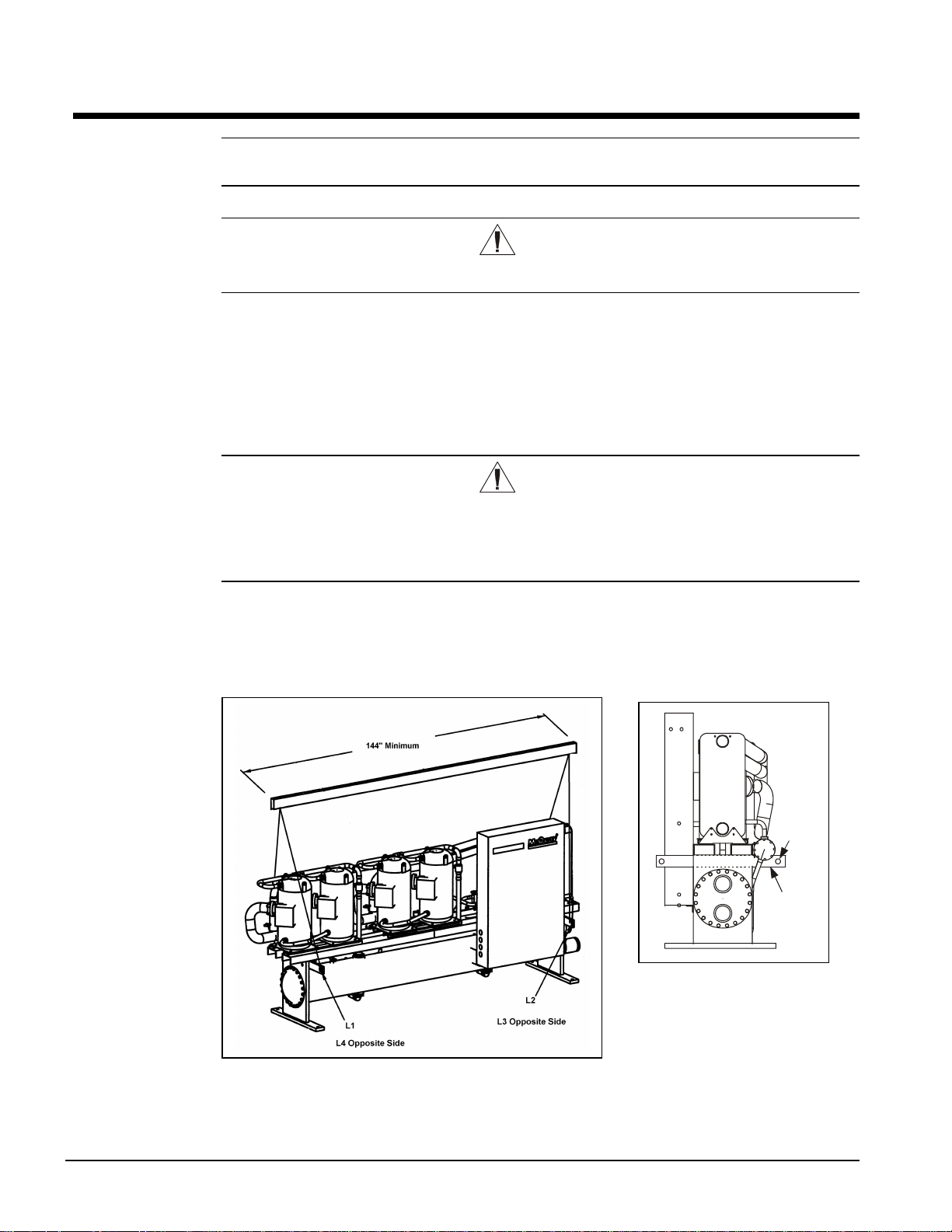
Figure 1, Lifting the Unit
(2) 2”
Lifting
Holes
Removable
Lifting
Bar
It is recommended that all moving and
handling be performed with skids or
dollies under the unit when possible
and that they not be removed until the
unit is in the final location.
Never put the weight of the unit against the control box.
In moving, always apply pressure to the base on the skids only and not to the piping or other
components. A long bar will help move the unit easily. Avoid dropping the unit at the end of the roll.
4 WGZ 030A through 100A IOMM WGZ-1
Page 5
If the unit must be hoisted, lift the unit from the removable lifting arms factory-bolted to each end of
the unit adjacent to the tube sheet by attaching cables or chains to the end of the arms. A spreader bar
must be used to protect the piping, control panel and other areas of the chiller (see Figure 1). The
arms should be removed and discarded after use.
Do not at tach sl ings to pip ing or e quipment. Do not attempt to lift the unit by lifting points mounted
on the compressors. They are for lifting only the compressor should one need to be removed from the
unit. Move unit in the upright horizontal position at all times. Set unit down gently when lowering
from the truck or rollers.
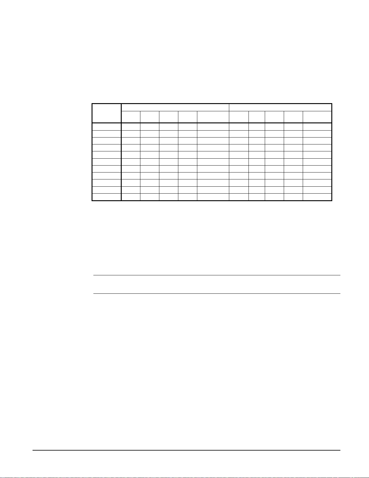
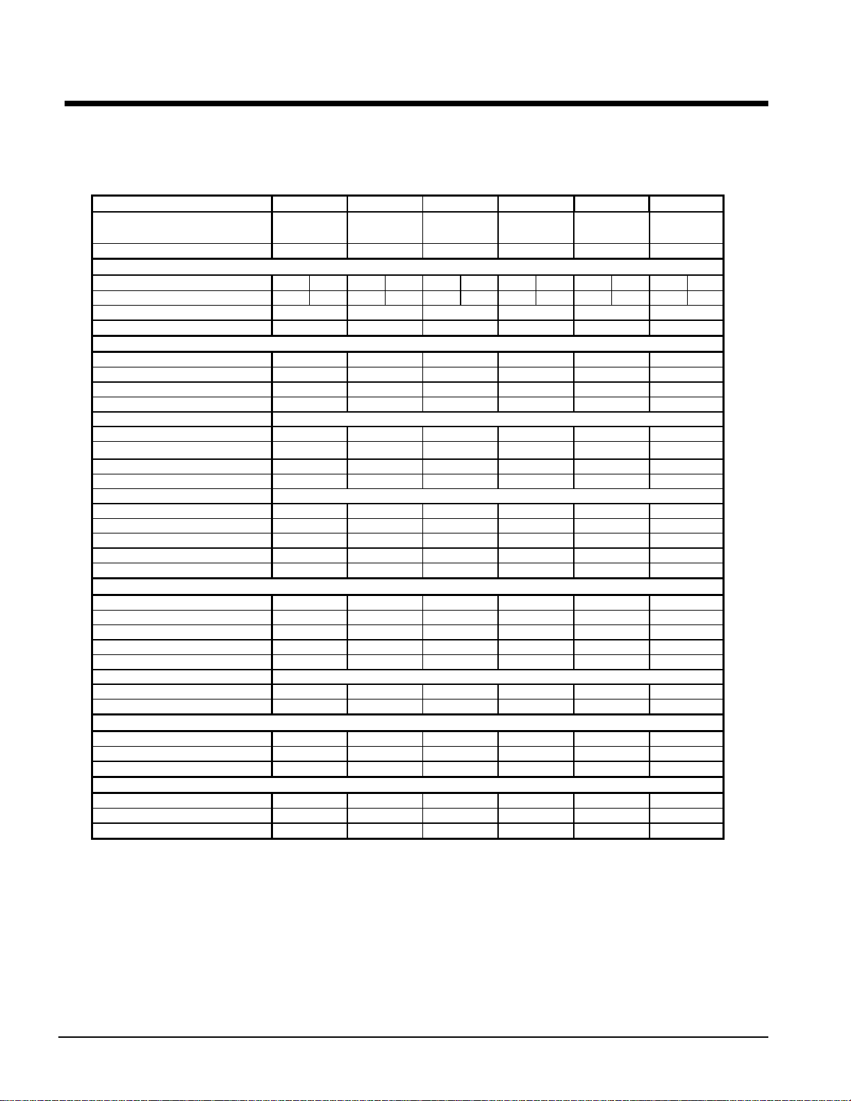
Table 1, Lifting Loads
Model
WGZ 030 564 616 655 715 2551 469 502 562 601 2134
WGZ 035 572 626 672 736 2606 473 507 576 617 2172
WGZ 040 584 641 695 764 2684 477 514 592 637 2219
WGZ 045 596 658 717 792 2763 486 525 610 659 2281
WGZ 050 604 668 739 817 2828 487 527 625 676 2315
WGZ 055 646 719 761 846 2973 526 577 643 705 2452
WGZ 060 800 892 855 953 3500 620 673 675 733 2701
WGZ 070 863 966 890 996 3716 673 735 700 764 2871
WGZ 080 900 1009 961 1077 3947 702 769 763 837 3071
WGZ 090 908 1021 1019 1145 4094 700 769 812 892 3172
WGZ 100 916 1031 1059 1191 4197 696 771 841 931 3238
L1 L2 L3 L4
Package Units (lbs. Less Condenser Units (lbs)
Shipping
Weight
L1 L2 L3 L4
Shipping
Weight
Location
WGZ chillers are designed for indoor application and must be located in an area where the
surrounding ambient temperature is 40°F (4°C) or above. A good rule of thumb is to place units
where ambient temperatures are at least 5°F (3°C) above the leaving water temperature.
Because of the electrical control devices, the units should not be exposed to the weather. A plastic
cover over the control box is supplied as temporary protection during shipment. A reasonably level
and sufficiently strong floor is required for the water chiller. If necessary, additional structural
members should be provided to transfer the weight of the unit to the nearest beams.
Note: Unit shipping and operating weights are given in Table 1 and in the physical data
tables beginning on page 26.
Space Requirements for Connections and Servicing
The chilled water and condenser water (on units with a water-cooled condenser) piping enters and
leaves the unit from the right side when looking at the control panel. Left-hand condenser
connections are an option. A clearance of at least 3 feet (1219 mm), or more if codes require, should
be provided beyond this piping and on all other sides and ends of the unit for general servicing or for
changing the compressors, if it ever becomes necessary.
On units equipped with a water-cooled condenser (Type WGZ-AW) clearance should also be
provided for cleaning or removal of condenser tubes on one end of the unit. The clearance for
cleaning depends on the type of apparatus used, but can be as much as the length of the condenser (10
feet, 3050 mm). Tube replacement requires the tube length of 10 feet (3050 mm) plus one to two feet
of workspace. This space can often be provided through a doorway or other aperture.
Placing the Unit
The small amount of vibration normally encountered with the water chiller makes this unit
particularly desirable for basement or ground floor installations where the unit can be mounted
directly to the floor. The floor construction should be such that the unit will not affect the building
structure, or transmit noise and vibration into the structure.
IOMM WGZ-1 WGZ 030A through 100A 5
Page 6
Vibration Isolators
It is recommended that isolators be used on all upper level installations or in areas where vibration
transmission is a consideration.
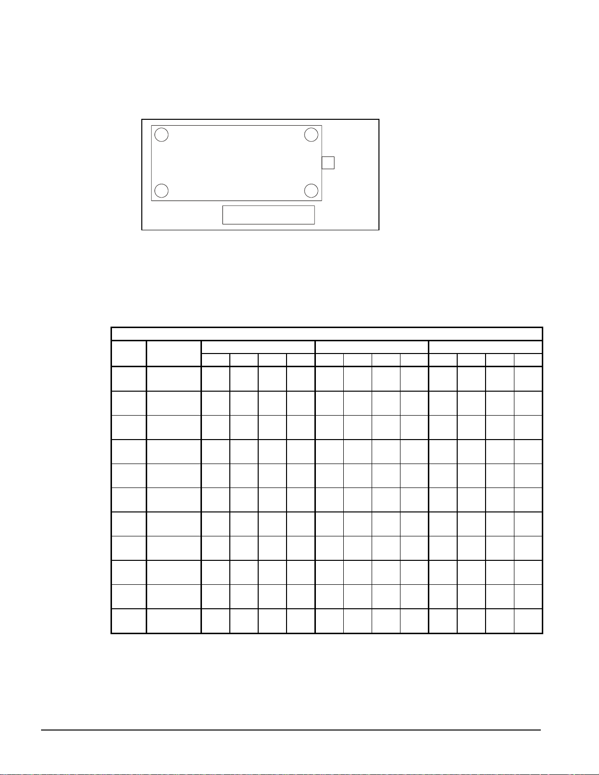
Figure 2, Isolator Locations
4
LB
1
LF
Control Panel
RB
FRF
3
Water
Connections
2
flushing, charging, etc., is completed, the springs are adjusted upward to loosen the blocks or shims
that are then removed.
A rubber anti-skid pad should be used under isolators if hold-down bolts are not used.
Installation of spring isolators requires flexible piping connections and at least three feet of flexible
electrical conduit to avoid straining the piping and transmitting vibration and noise.
Table 2, Weights & Mountings
ARRANGEMENT WGZ-AW, WITH WATER-COOLED CONDENSERS
Unit
Size
030
035
040
045
050
055
060
070
080
090
100
Opr. Wt.
Lbs. (kg)
2692
(1219)
2760
(1250)
2866
(1298)
2966
(1344)
3058
(1385)
3213
(1455)
3809
(1725)
4025
(1823)
4289
(1943)
4484
(2031)
4627
(2096)
Corner Weight Lbs (kg) Neoprene-In-Shear Mountings Spring-Flex Mountings
1 2 3 4 1 2 3 4 1 2 3 4
589
648
692
762
RP-3
RP-3
(267)
(294)
(314)
(345)
Green
Green
599
661
713
787
RP-3
RP-3
(271)
(299)
(323)
(356)
Green
Green
616
682
744
824
RP-3
RP-3
(279)
(309)
(337)
(373)
Green
Green
632
702
773
860
RP-3
RP-3
(286)
(318)
(350)
(389)
Green
Green
644
718
802
894
RP-3
RP-3
(292)
(325)
(363)
(405)
Green
Green
688
772
826
927
RP-3
RP-3
(312)
(350)
(374)
(420)
Gray
Gray
853
959
940
1057
RP-3
RP-3
(386)
(435)
(426)
(479)
Gray
Gray
916
(415)
958
(434)
974
(441)
989
(448)
1033
(468)
1082
(490)
1103
(500)
1121
(508)
975
(442)
1056
(478)
1129
(511)
1179
(534)
1100
(498)
1193
(540)
1278
(579)
1337
(606)
RP-3
Gray
RP-3
Gray
RP-3
Gray
RP-3
Gray
RP-3
Gray
RP-3
Gray
RP-4
Black
RP-4
Black
Transfer the unit as indicated under
“Moving the Unit.” In all cases, set
the unit in place and level with a spirit
level. When spring-type isolators are
required, install springs running under
the main unit supports.
The unit should be set initially on
shims or blocks at the listed spring
free height. When all piping, wiring,
RP-3
RP-3
CP-1
CP-1
Green
Green
RP-3
RP-3
Gray
RP-3
Gray
RP-3
Gray
RP-3
Gray
RP-3
Gray
RP-3
Gray
RP-3
Gray
RP-4
Black
RP-4
Black
Gray
RP-3
Gray
RP-3
Gray
RP-3
Gray
RP-3
Gray
RP-3
Gray
RP-3
Gray
RP-4
Black
RP-4
Black
RP-4
Black
RP-4
Black
Orange
CP-1
Orange
CP-1
Orange
CP-1
Orange
CP-1
Orange
CP-1
Orange
CP-1
Green
CP-1
Gray
CP-1
Gray
CP-1
Gray
CP-1
Gray
Orange
CP-1
Orange
CP-1
Orange
CP-1
Orange
CP-1
Orange
CP-1
Gray
CP-1
Green
CP-1
Gray
CP-1
Gray
CP-1
White
CP-1
White
Orange
Orange
Orange
Green
Green
White
White
CP-1
CP-1
CP-1
CP-1
CP-1
CP-1
Gray
CP-1
Gray
CP-1
Gray
CP-1
Gray
CP-1
CP-1
CP-1
Green
CP-1
Green
CP-1
Orange
CP-1
Green
CP-1
Green
CP-1
Gray
CP-1
Gray
CP-1
White
CP-1
White
CP-2
Green
CP-2
Green
6 WGZ 030A through 100A IOMM WGZ-1
Page 7
Unit
Size
030
035
040
045
050
055
060
070
080
090
100
Opr. Wt.
Lbs. (kg)
2162
(979)
2204
(998)
2257
(1022)
2329
(1055)
2370
(1074)
2505
(1135)
2771
(1255)
2942
(1333)
3154
(1429)
3271
(1482)
3346
(1516)
ARRANGEMENT WGZ-AA, FOR REMOTE CONDENSER
Corner Weight Lbs (kg) Neoprene-In-Shear Mountings Spring-Flex Mountings
1 2 3 4 1 2 3 4 1 2 3 4
468
502
575
616
RP-3
RP-3
RP-3
RP-3
CP-1
CP-1
CP-1
CP-1
(212)
(227)
(260)
(279)
Green
Green
Green
Green
Purple
Purple
Orange
Orange
472
507
590
634
RP-3
RP-3
RP-3
RP-3
CP-1
CP-1
CP-1
CP-1
(214)
(230)
(267)
(287)
Green
Green
Green
Green
Purple
Purple
Orange
Orange
477
514
609
657
RP-3
RP-3
RP-3
RP-3
CP-1
CP-1
CP-1
CP-1
(216)
(233)
(276)
(297)
Green
Green
Green
Green
Purple
Purple
Orange
Orange
487
526
633
684
RP-3
RP-3
RP-3
RP-3
CP-1
CP-1
CP-1
CP-1
(220)
(238)
(287)
(310)
Green
Green
Green
Green
Purple
Purple
Orange
Orange
488
528
650
704
RP-3
RP-3
RP-3
RP-3
CP-1
CP-1
CP-1
CP-1
(221)
(239)
(295)
(319)
Green
Green
Green
Green
Purple
Purple
Orange
Orange
526
578
668
734
RP-3
RP-3
RP-3
RP-3
CP-1
CP-1
CP-1
CP-1
(238)
(262)
(303)
(332)
Green
Green
Green
Green
Purple
Purple
Orange
Orange
619
674
707
770
RP-3
RP-3
RP-3
RP-3
CP-1
CP-1
CP-1
CP-1
(280)
(305)
(320)
(349)
Green
672
(304)
702
(318)
700
(317)
697
(316)
736
(333)
771
(349)
771
(349)
773
(350)
732
(332)
801
(363)
857
(388)
890
(403)
801
(363)
880
(399)
944
(427)
987
(447)
RP-3
Green
RP-3
Green
RP-3
Green
RP-3
Green
Green
Green
RP-3
RP-3
Gray
RP-3
Gray
RP-3
Gray
Gray
RP-3
Gray
RP-3
Gray
RP-3
Gray
RP-3
Gray
Gray
RP-3
Gray
RP-3
Gray
RP-3
Gray
RP-3
Gray
Orange
CP-1
Orange
CP-1
Orange
CP-1
Orange
CP-1
Orange
Orange
CP-1
Orange
CP-1
Green
CP-1
Green
CP-1
Green
Green
CP-1
Green
CP-1
Green
CP-1
Green
CP-1
Green
Green
CP-1
Green
CP-1
Gray
CP-1
Gray
CP-1
Gray
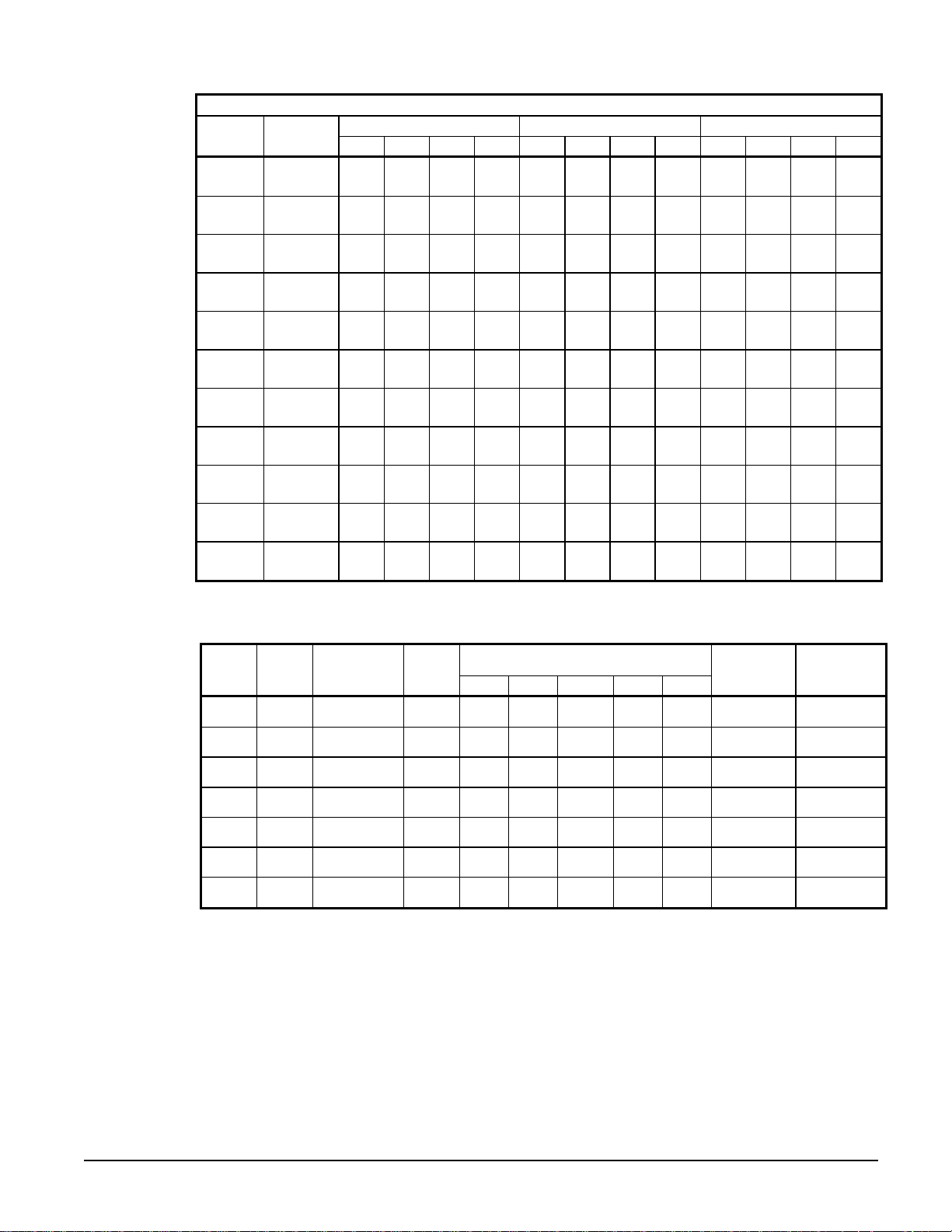
Table 3, Spring Flex Isolators
6.0
(152.4)
6.0
(152.4)
6.0
(152.4)
6.0
(152.4)
6.0
(152.4)
6.0
(152.4)
9.0
(228.6)
Dimensions
In. (mm)
4.7
(119.4)
4.7
(119.4)
4.7
(119.4)
4.7
(119.4)
4.7
(119.4)
4.7
(119.4)
7.7
(195.6)
Housing
CP-1
CP-1
CP-1
CP-1
CP-1
CP-1
CP-2
NOTE: CP-1 housing contains one spring. CP-2 housing contains two identical springs.
Spring
Color
Red
Purple
Orange
Green
Gray
White
Green
Max. Load
Each
Lbs. (kg)
450
(204)
600
(272)
750
(340)
900
(408)
1100
(498)
1300
(589)
1800
(815)
Defl.
In. (mm)
0.5
(12.7)
0.5
(12.7)
0.5
(12.7)
0.5
(12.7)
0.5
(12.7)
0.5
(12.7)
0.5
(12.7)
A B C D E
7.5
(190.5)
7.5
(190.5)
7.5
(190.5)
7.5
(190.5)
7.5
(190.5)
7.5
(190.5)
10.2
(259.1)
2.7
(68.6)
2.7
(68.6)
2.7
(68.6)
2.7
(68.6)
2.7
(68.6)
2.7
(68.6)
2.7
(68.6)
5.5
(139.7)
5.5
(139.7)
5.5
(139.7)
5.5
(139.7)
5.5
(139.7)
5.5
(139.7)
5.75
(146.0)
Housing
Part Number
226102B-00 226115A-00
226102B-00 226116A-00
226102B-00 226117A-00
226102B-00 226118A-00
226102B-00 226119A-00
226102B-00 226120A-00
226103B-00 (2) 226118A-00
Spring
Part Number
IOMM WGZ-1 WGZ 030A through 100A 7
Page 8
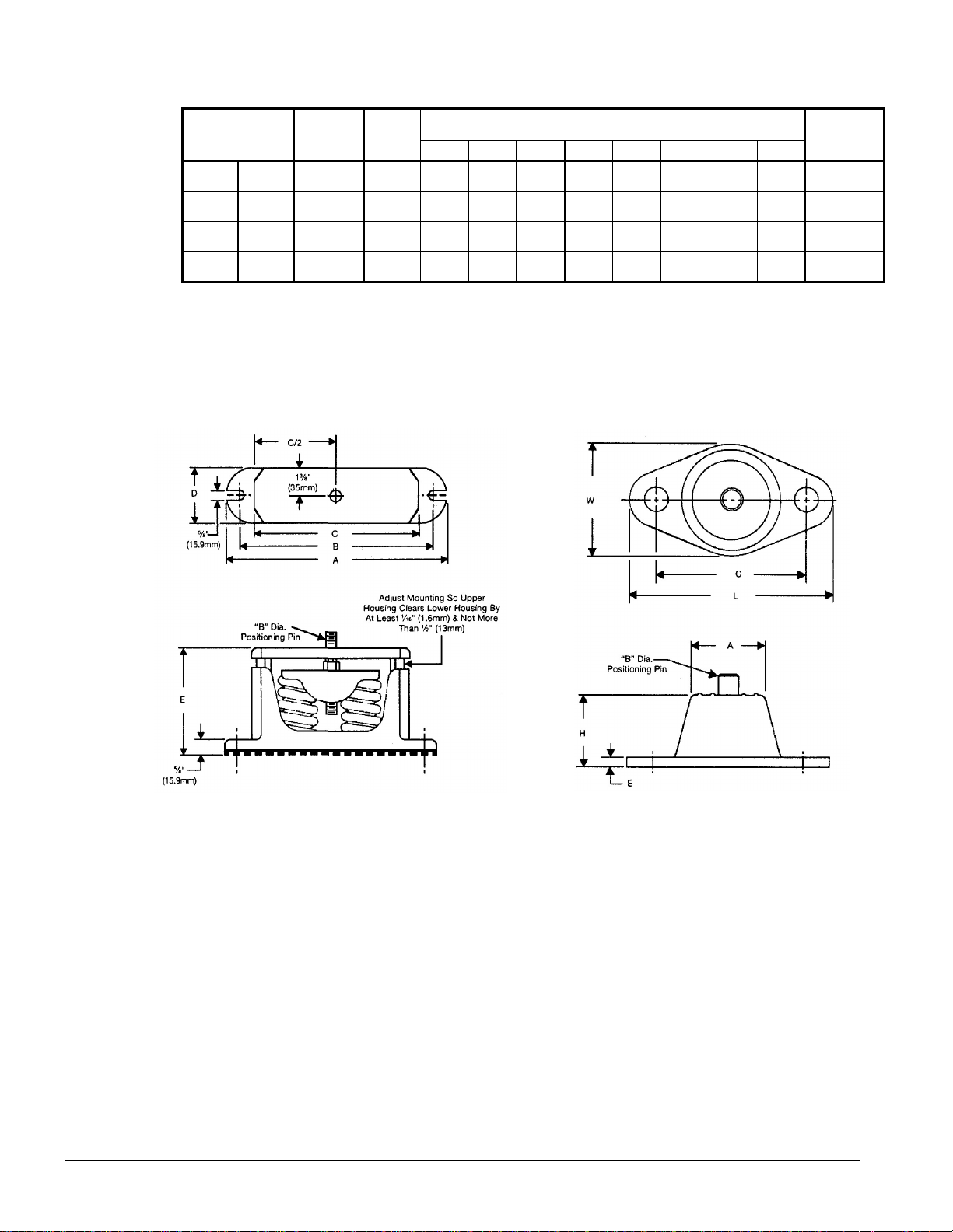
Table 4, Neoprene-in-Shear Isolators
4.1
4.1
5.0
5.0
Dimensions
In. (mm)
0.56
(14.2)
0.56
(14.2)
0.56
(14.2)
0.56
(14.2)
0.25
(6.4)
0.25
(6.4)
0.25
(6.4)
0.25
(6.4)
1.75
(44.4)
1.75
(44.4)
1.6
(41.1)
1.6
(41.1)
5.5
(165)
5.5
(165)
6.5
(165.1)
6.5
(165.1)
3.4
(85.7)
3.4
(85.7)
4.6
(116.8)
4.6
(116.8)
McQuay
Part Number
216397A-03
216397A-05
216398A-04
216398A-01
Type
RP-3 Green
RP-3 Gray
RP-4 Black
RP-4 Red
Max. Load
Each
Lbs. (kg)
750
(339)
1100
(498)
1500
(679)
2250
(1019)
Defl.
In. (mm)
0.25
(6.4)
0.25
(6.4)
0.25
(6.4)
0.25
(6.4)
A B C D (1) E H L W
2.5
(63.5)
2.5
(63.5)
3.75
(95.3)
3.75
(95.3)
0.5
(12.7)
0.5
(12.7)
0.5
(12.7)
0.5
(12.7)
(104.1)
(104.1)
(127.0)
(127.0)
Note (1) "D" is the mounting hole diameter.
Figure 3, Spring Flex Mountings Figure 4, Single Neoprene-in-Shear
Mounting
8 WGZ 030A through 100A IOMM WGZ-1
Page 9

Water Piping
General
Due to the variety of piping practices, it is advisable to follow the recommendations of local
authorities for code compliance. They can supply the installer with the proper building and safety
codes required for a safe and proper installation.
Basically, the piping should be designed with a minimum number of bends and changes in elevation
to keep system cost down and performance up. Other piping design considerations include:
1. All piping should be installed and supported to prevent the chiller connections from bearing any
2. Vibration eliminators to reduce vibration and noise transmission to the building.
3. Shutoff valves to isolate the unit from the piping system during unit servicing.
4. Manual or automatic air vent valves at the high points of the system. Drains should be placed at
5. Some means of maintaining ad equate system water pressure ( e.g., expansion ta nk or regulating
6. Temperature and pressure indicators located within 3 feet (0.9 meters) of the inlet and outlet of
7. A strainer or some means of removing foreign matter from the water before it enters the pump is
strain or weight of the system piping.
the lowest points in the system.
valve).
the vessels to aid in unit servicing.
recommended. It should be placed far enough upstream to pr event cavitation at the pump inlet
(consult pump manufacturer for recommendations). The use of a strainer will prolong pump life
and thus maintain system performance.
Important Note
A cleanable 40-mesh strainer must also be placed in the water line j ust prior to the inlet of
the evaporator. This will aid in preventing foreign material from entering and decreasing the
performance of the evaporator.
8. If the unit is used as a replacement chiller on a previously existing piping system, the system
should be thoroughly flushed prior to unit installation. Regular water anal ysis a nd chemical
water treatment on the evaporator and condenser is recommended immediately upon equipment
start-up.
9. In the event glycol is added to the water system, as an afterthought for freeze protection,
recognize that the refrigerant suction pressure will be lower, cooling performance less, and water
side pressure drop will be higher. If the percentage of glycol is large, or if propylene glycol is
used instead of ethylene glycol, the added pressure drop and loss of performance could be
substantial. Reset the freezestat and low leaving water alarm temperatures. The freezestat is
factory set to default at 36°F (2.2°C). Reset the freezestat setting to approximately 4° to 5°F
(2.3° to 2.8°C) below the leaving chilled water setpoint temperature. See the section titled
“Glycol Solutions” for additional information concerning the use of glycol.
10. A preliminary leak check of the water piping should be made before filling the system.
Note: A water f low switch or pressur e differential switch m ust be m ounted in the evaporator
outlet water line to signal that there is water flow before the unit will start.
IOMM WGZ-1 WGZ 030A through 100A 9
Page 10
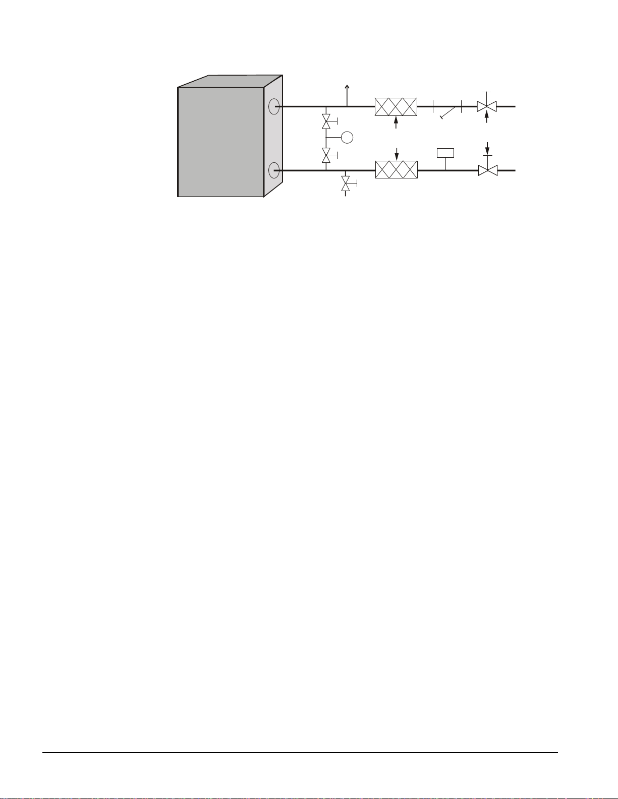
Figure 5, Typical Field Evaporator Water Piping
Ai
r
Vent
Inlet
Strainer
Isolation
Valves
Outlet
P
Drain
Vibration
Eliminators
Flow
Switch
NOTE: Water piping must be supported independently from the unit.
System Water Volume
It is important to have adequate water volume in the system to provide an opportunity for the chiller
to sense a load change, adjust to the change, and then stabilize. As the expected load change becomes
more rapid, a greater water volume is needed. The system water volume is the total amount of water
in the evaporator, air handling equipment, and associated piping. If the water volume is too low,
operational problems can occur including rapid compressor cycling, rapid loading and unloading of
compressors, erratic refrigerant flow in the chiller, improper motor cooling, shortened equipment life
and other undesirable occurrences.
For normal comfort cooling applications where the cooling load changes relatively slowly, we
recommend a minimum system volume of four minutes times the flow rate (GPM). For example, if
the design chiller flow rate is 120 gpm, we recommend a minimum system volume of 480 gallons
(120 gpm x 4 minutes).
For process applications where the cooling load can change rapidly, additional system water volume
is needed. A process example would be the quenching of hot metal objects. The load would be very
stable until the hot metal is dipped into the water tank. Then, the load would increase drastically.
Since there are many other factors that can influence performance, systems can successfully operate
below these suggestions. However, as the water volume decreases below these guidelines, the
possibility of problems increases.
Variable Chilled Water Flow
Reducing chilled water flow in proportion to load can reduce total system power consumption.
Certain restrictions apply to the amount and rate of flow change. The rate of flow change should be a
maximum of 10 percent of the change, per minute. Do not reduce flow lower than the minimum
flows listed in the pressure drop data on page 15.
Chilled Water Piping
The system water piping must be flushed thoroughly prior to making connections to the unit
evaporator. It is required that a 1.0 mm (16 to 20 mesh) strainer be installed in the return water line
before the inlet to the chiller. Lay out the water piping so the chilled water circulating pump
discharges into the evaporator inlet.
The return water line must be piped to the evaporator inlet connection and the supply water line must
be piped to the evaporator outlet connection. If the evaporator water is piped in the reverse direction,
a substantial decrease in capacity and efficiency of the unit will be experienced.
A flow switch must be installed in the horizontal piping of the supply (evaporator outlet) water line to
prove water flow before starting the unit.
10 WGZ 030A through 100A IOMM WGZ-1
Page 11
g
Drain connections should be provided at all low points in the system to permit complete drainage of
the system. Air vents should be located at the high points in the system to purge air out of the system.
The evaporators are not equipped with vent or drain connections and provision must be made in the
entering and leaving chilled water piping for venting and draining.
Pressure gauges should be installed in the inlet and outlet water lines to the evaporator. Pressure drop
through the evaporator should be measured to determine water flow from the flow/pressure drop
curves on page 15. Vibration eliminators are recommended in both the supply and return water lines.
Chilled water piping should be insulated to reduce heat loss and prevent condensation. Complete unit
and system leak tests should be performed prior to insulating the water piping. Insulation with a
vapor barrier would be the recommended type of insulation. If the vessel is insulated, the vent and
drain connections must extend beyond the proposed insulation thickness for accessibility.
Chillers not run in the winter should have their water systems thoroughly drained if subje ct to subfreezing temperatures. If the chiller operates year-round, or if the system is not drained for the winter,
the chilled water piping exposed to sub-freezing ambient temperatures should be protected against
freezing by wrapping the lines with a heater cable. In addition, an adequate percentage of glycol
should be added to the system to further protect the system during low ambient temperature periods.
It should be noted that water piping that has been left drained is subject to more corrosion than if
filled with water. Use of a Vapor Corrosion Inhibitor (VCI) or some other protection should be
considered.
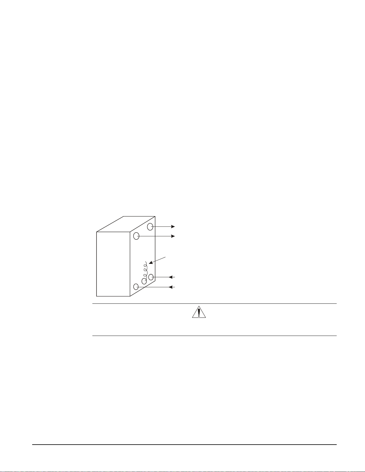
Chilled Water Sensor
Figure 6, Thermostat Well Location
Suction
Circuit #1
Suction
Circuit #2
Leavin
Chilled
Water Sensor
The chilled water sensor is factory installed in the
leaving water connection on the evaporator. Care
should be taken not to damage the sensor cable or
lead wires when working around the unit. It is
also advisable to check the lead wire before
running the unit to be sure that it is firmly
anchored and not rubbing on the frame or any
Liquid
Circuit #2
Liquid
Circuit #1
other component. If the sensor is ever removed
from the well for servicing, care must be taken to
not wipe off the heat-conducting compound
supplied in the well.
CAUTION
The thermostat bulb should not be exposed to water temperatures above 125°F
(51.7°C) since this will damage it.
Flow Switch
A water flow switch must be mounted in the leaving evaporator and condenser water line to prove
adequate water flow before the unit can start. This will safeguard against slugging the compressors
on start-up. It also serves to shut down the unit in the event that water flow is interrupted to guard
against evaporator freeze-up.
A flow switch is available from McQuay under part number 01750330. It is a “paddle” type switch
and adaptable to any pipe size from 1 in. (25 mm) to 6 in. (152 mm) nominal. Certain minimum flow
rates are required to close the switch and are listed in Table 5. Electrical connections in the unit
control center should be made at terminals 33 and 43 (chilled water) and 41 and 53 (condenser
water). The normally open contacts of the flow switch should be wired between these two terminals.
There is also a set of normally closed contacts on the switch that could be used for an indicator light
or an alarm to indicate when a “no flow” condition exists.
IOMM WGZ-1 WGZ 030A through 100A 11
Page 12
1. Apply pipe sealing compound to only the threads of the switch and screw unit into 1 in. (25 mm)
T
reducing tee. The flow arrow must be pointed in the correct direction.
2. Piping should provide a straight length before and after the flow switch of at least five times the
pipe diameter without any valves, elbows, or other flow restricting elements.
3. Trim flow switch paddle if needed to fit the pipe diameter. Make sure paddle does not hang up in
pipe.
CAUTION
Make sure the arrow on the side of the switch is pointed in the direction of flow. The
flow switch is designed to handle the control voltage and should be connected
according to the wiring diagram (see wiring diagram inside control box door).
Incorrect installation will cause improper operation and possible evaporator damage.
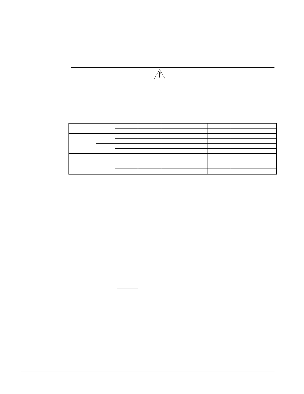
Table 5, Flow Switch Flow Rates
Pipe Size
Minimum
Adjustment
Maximum
Adjustment
Flow
No
Flow
Flow
No
Flow
inch 2 2 1/2 3 4 5 6
mm 51 63 76 102 (125) (150)
gpm 13.7 17.9 24.2 35.3 48.6 60.3
Lpm 51.8 67.8 91.6 134.0 184.0 228.0
gpm 9.4 12.1 16.4 27.0 37.4 46.8
Lpm 35.6 45.8 62.1 102.0 142.0 177.0
gpm 56.4 71.3 89.0 118.0 178.0 245.0
Lpm 214.0 270.0 337.0 446.0 674.0 927.0
gpm 47.4 59.2 72.5 105.0 160.0 225.0
Lpm 179.0 224.0 274.0 397.0 606.0 852.0
Glycol Solutions
When using a glycol solution, the chiller capacity, flow rate, evaporator pressure drop, and chiller
power input can be calculated using the following formulas and reference to Table 6 for ethylene
glycol and Table 7 for propylene glycol.
1. Capacity, Capacity is reduced compared to that with plain water. To find the reduced value,
multiply the chiller’s capacity when using water by the capacity correction factor C to find the
chiller’s capacity when using glycol.
2. Flow, To determine evaporator gpm (or ∆T) knowing ∆T (or gpm) and capacity:
GPMGlycol
24
=
For Metric Applications -- Determine evaporator lps (or ∆T) knowing ∆T (or lps) and kW:
LpsGlycol
3.
Pressure Drop, To determine glycol pressure drop through the cooler, enter the water p ressure
kW
=
∆
18.4
drop graph on page 15 at the actual glycol flow. Multiply the water pressure drop found there by
P to obtain corrected glycol pressure drop.
4.
Power, To determine glycol system kW, multiply the water system kW by factor K.
CapacityGlycolx
∆
TablesfromGCorrectionFlowx
Tx
TablesFromGCorrectionFlowx
Test coolant with a clean, accurate, glycol solution hydrometer (similar to that found in service
stations) to determine the freezing point. Obtain percent glycol from the freezing point found in
Table 6 or Table 7. On glycol applications the supplier normally recommends that a minimum of
25% solution by weight be used for protection against corrosion or the use of additional inhibitors.
12 WGZ 030A through 100A IOMM WGZ-1
Page 13
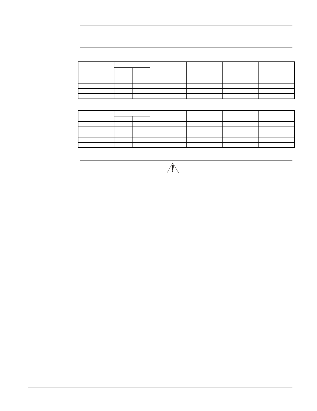
Note: The effect of glycol in the condenser is negligible. As glycol increases in temperature,
its characteristics have a tendency to mirror those of water. Therefore, for selection
purposes, there is no derate in capacity for glycol in the condenser.
Table 6, Ethylene Glycol
Glycol
10 26 -3 0.991 0.996 1.013 1.070
20 18 -8 0.982 0.992 1.040 1.129
30 7 -14 0.972 0.986 1.074 1.181
40 -7 -22 0.961 0.976 1.121 1.263
50 -28 -33 0.946 0.966 1.178 1.308
Freezing Point Percent
°F °C
C (Capacity) K (Power) G (Flow)
P (Pressure
Drop)
Table 7, Propylene Glycol
Glycol
10 26 -3 0.987 0.992 1.010 1.068
20 19 -7 0.975 0.985 1.028 1.147
30 9 -13 0.962 0.978 1.050 1.248
40 -5 -21 0.946 0.971 1.078 1.366
50 -27 -33 0.929 0.965 1.116 1.481
Freezing Point Percent
°F °C
C (Capacity) K (Power) G (Flow)
P (Pressure
Drop)
CAUTION
Do not use automotive grade antifreeze. Industrial grade glycols must be used.
Automotive antifreeze contains inhibitors which cause plating on copper tubes. The
type and handling of glycol used must be c onsistent with local codes.
Condenser Water Piping
Arrange the condenser water so the water enters the bottom connection of the condenser. The
condenser water will discharge from the top connection. Failing to arrange the condenser water as
stated above will negatively affect the capacity and efficiency.
Pressure gauges should be installed in the inlet and outlet water lines to the condenser. Pr essure drop
through the c ondenser should be measured to determine flo w on the pressure drop/flow curves on
page 16. Vibration eliminators are recommended in both the supply and return water lines.
Water-cooled condensers can be piped for use with cooling towers, well water, or heat recovery
applications. Cooling tower applications should be made with consideration of freeze protection and
scaling problems. Contact the cooling tower manufacturer for equipment characteristics and
limitations for the specific application.
Head pressure control must be provided if the entering condenser water can fall below 60°F. T h e
WGZ condenser has two refrigerant circuits with a common condenser water circuit. This
arrangement makes head pressure control with discharge pressure actuated control valves difficult.
If for some reason the tower water temperature cannot be maintained at a 60°F minimum, or whe n
pond, lake, or well water that can fall below 60°F (15°C) is used as the condensing medium, special
discharge pressure control must be used. A water recirculating system with recirculating pump as
shown in Figure 7 is recommended. This system also has the advantage of maintaining tube velocity
to help prevent tube fouling. The pump should cycle with the chiller.
IOMM WGZ-1 WGZ 030A through 100A 13
Page 14
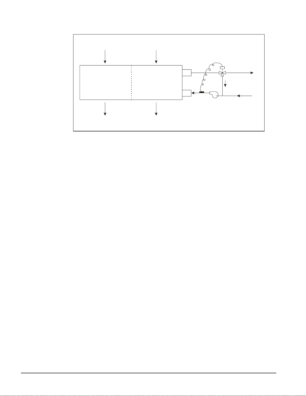
Figure 7, Recirculating Discharge Pressure Control System
Circuit #1
Inlet
Circuit #2
Inlet
Condenser
Temperature
Control
Valve
Condenser
Water
Circuit #1
Outlet
Circuit #2
Outlet
Water Pressure Drop
The vessel flow rates must fall between the minimum and maximum values shown on the appropriate
evaporator and condenser curves. Flow rates below the minimum values shown will result in laminar
flow that will reduce efficiency, cause erratic operation of the electronic expansion valve and could
cause low temperature cutoffs. On the other hand, flow rates exceeding the maximum values shown
can cause erosion in the evaporator.
Measure the chilled water pressure d rop through the evaporator at fie ld-installed pressure ta ps. It is
important not to include valves or strainers in these readings.
14 WGZ 030A through 100A IOMM WGZ-1
Page 15
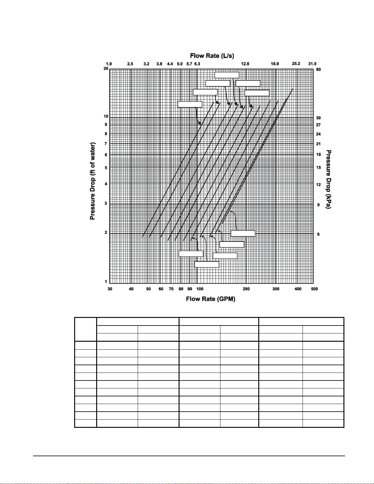
Figure 8, Evaporator Water Pressure Drop, WGZ 030A through 100A
WGZ 045
WGZ 040
WGZ 035
WGZ 030
WGZ 050
WGZ 055
WGZ 100
WGZ 090
WGZ 060
WGZ 080
WGZ 070
WGZ
Model
gpm L/s Ft. kPa gpm L/s Ft. kPa gpm L/s Ft. kPa
030 47.0 3.0 1.6 4.8 75.2 4.7 3.9 11.7 125.3 7.9 10.9 32.4
035 51.9 3.3 1.6 4.8 83.1 5.2 3.9 11.7 138.5 8.7 11.1 33.0
040 60.1 3.8 1.8 5.5 96.2 6.1 4.2 12.4 160.4 10.1 12.0 35.8
045 66.9 4.2 1.8 5.5 107.0 6.8 4.2 12.4 178.4 11.3 11.8 35.1
050 73.6 4.6 1.8 5.5 117.8 7.4 4.6 13.8 196.3 12.4 12.0 35.8
055 82.3 5.2 2.1 6.2 131.7 8.3 4.2 12.4 219.5 13.9 11.8 35.1
060 91.0 5.7 2.1 6.2 145.6 9.2 4.2 12.4 242.7 15.3 12.9 38.5
070 104.1 6.6 1.8 5.5 166.6 10.5 4.4 13.1 277.7 17.5 12.2 36.5
080 115.9 7.3 1.8 5.5 185.4 11.7 4.4 13.1 309.1 19.5 12.2 36.5
090 129.2 8.1 1.8 5.5 206.6 13.0 4.2 12.4 344.4 21.7 11.8 35.1
100 142.4 9.0 1.8 5.5 227.8 14.4 4.9 14.5 379.7 24.0 13.4 39.9
Minimum Flow Nominal Flow Maximum Flow
Flow Rate Pressure Drop Flow Rate Pressure Drop Flow Rate Pressure Drop
Note : Mi ni mum, no mina l , a nd max imu m fl ows ar e a t a 1 6°F, 10°F, and 6°F chilled water temperature range
respectively, and at ARI tons.
IOMM WGZ-1 WGZ 030A through 100A 15
Page 16
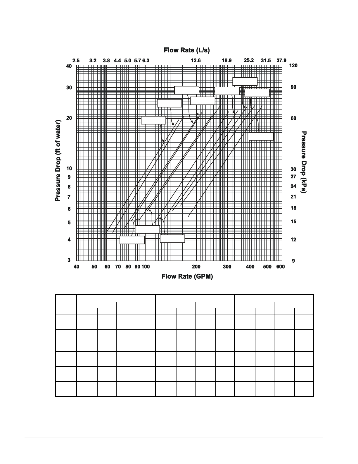
Figure 9, Condenser Water Pressure Drop, WGZ 030AW through 100AW
WGZ 080
WGZ 035
WGZ 030
WGZ 040
WGZ 045
WGZ 070
WGZ 090
WGZ 100
WGZ 055
WGZ 050
WGZ 060
WGZ
Model
030 58.7 3.8 4.2 12.5 94.0 6.0 8.6 25.8 156.6 10.0 20.0 59.9
035 64.9 4.2 4.4 13.1 103.8 6.6 8.9 26.6 173.1 11.1 20.4 61.2
040 75.2 4.8 4.6 13.7 120.3 7.7 9.0 26.9 200.5 12.8 20.2 60.7
045 83.6 5.4 5.0 15.1 133.8 8.6 9.7 29.1 223.0 14.3 21.7 65.0
050 92.0 5.9 5.1 15.3 147.3 9.4 9.5 28.6 245.4 15.7 20.8 62.5
055 102.9 6.6 5.9 17.6 164.6 10.5 10.7 32.0 274.4 17.6 23.1 69.2
060 113.8 7.3 5.0 14.9 182.0 11.6 9.7 29.2 303.3 19.4 21.9 65.9
070 130.2 8.3 5.3 15.8 208.3 13.3 10.0 30.0 347.2 22.2 22.0 66.1
080 144.9 9.3 5.8 17.4 231.8 14.8 10.7 32.1 386.4 24.7 23.2 69.6
090 161.4 10.3 6.2 18.7 258.3 16.5 11.1 33.2 430.5 27.6 23.4 70.2
100 178.0 11.4 5.4 16.1 284.8 18.2 10.1 30.4 474.7 30.4 22.4 67.1
gpm L/s Ft. kPa gpm L/s Ft. kPa gpm L/s Ft. kPa
Minimum Flow Nominal Flow Maximum Flow
Flow Rate Pressure Drop Flow Rate Pressure Drop Flow Rate Press ure Drop
16 WGZ 030A through 100A IOMM WGZ-1
Page 17

Refrigerant Piping
Unit with Remote Condenser
General
For remote condenser application (WGZ-AA) such as air-cooled or evaporative condenser, the
chillers are shipped with an R-22 holding charge. It is important that the unit be kept tightly closed
until the remote condenser is installed, piped to the unit and the high side evacuated.
Refrigerant piping, to and from the unit, should be sized and installed according to the latest
ASHRAE Handbook. It is important that the unit piping be properly supported with sound and
vibration isolation between tubing and hanger, and that the discharge lines be looped at the condenser
and trapped at the compressor to prevent refrigerant and oil from draining into the compressors.
Looping the discharge line also provides greater line flexibility.
The discharge gas valves, liquid line solenoids, filter-driers, moisture indicators, and thermostatic
expansion valves are all factory mounted as standard equipment with the water chiller.
A liquid line shutoff valve must be added in the field on remote condenser units between the liquid
line filter-drier and remote condenser.
After the equipment is properly installed, leak tested, and evacuated, it can be charged with R-22, and
run at design load conditions. Add charge until the liquid line sight glass is clear, with no bubbles
flowing to the expansion valve. Total operating charge will depend on the air-cooled condenser used
and volume of the refrigerant piping.
Note: On the arrangement WGZ-AA units (units with remote condensers), the installer is
required to record the refrigerant charge by stamping the total charge and the charge per
circuit on the serial plate in the appropriate blocks provided for this purpose.
The following discussion is intended for use as a general guide to the piping of air-cooled condensers.
Discharge lines must be designed to handle oil properly and to protect the compressor from damage
that can result from condensing liquid refrigerant in the line during shutdown. Total friction loss for
discharge lines of 3 to 6 psi (20.7 to 41.4 kPa) is considered good design. Careful consideration must
be given for sizing each section of piping to insure that gas velocities are sufficient at all operating
conditions to carry oil. If the velocity in a vertical discharge riser is too low, co nsiderable oil can
collect in the riser and the horizontal header, causing the compressor to lose its oil and result in
damage due to lack of lubrication. When the compressor load is increased, the oil that had collected
during reduc ed lo ad s ca n b e ca rr ie d a s a slug t hro ugh the system and ba ck t o t he c ompr esso r, where a
sudden increas e of oil concentration can cause liquid slugging and da mage to the compressor.
Any horizontal run of discharge piping should be pitched away from the compressor approximately
1/8 inch (6.4 mm) per foot (meter) or more. This is necessary to move, by gravity, any oil lying in the
header. Oil pockets must be avoided because oil needed in the compressor would collect at such
points and the compressor crankcase can become starved.
It is recommended that any discharge lines coming into a horizontal discharge header rise above the
centerline of the discharge header. This is necessary to prevent any oil or condensed liquid from
draining to the compressor head s when the compressor is not running.
IOMM WGZ-1 WGZ 030A through 100A 17
Page 18

In designing liquid lines, it is important that the liquid reach the expansion valve without flash gas
since this gas will reduce the capacity of the valve. Because “flashing” can be caused by a pressure
drop in the liquid line, the pressure losses due to friction and changes in static head should be kept to
a minimum.
A check valve must be installed in the liquid line in all applications where the ambient temperature
can drop below the equipment room temperature. This prevents liquid migration to the condenser,
helps maintain a supply of refrigerant in the liquid line for initial start-up, and keeps liquid line
pressure high enough on “off” cycle to keep the expansio n valve closed.
On systems as described above, a relief valve or relief-type check valve, must be used in the liquid
line as shown in piping systems (shown in Figure 11) to relieve dangerous hydraulic pre ssures that
could be created as cool liquid refrigerant in the line between the check valve and the expansion or
shutoff valve warms up. A relief device is also recommended in the hot gas piping at the condenser
coil as shown in Figure 10 and Figure 11.
T y pical A rrangement s
Figure 10 illustrates a typical piping arrangement involving a remote air-cooled condenser located at
a higher elevation than the compressor and receiver. This arrangement is commonly encountered
when the air-cooled condenser is on a roof and the compressor and receiver are on grade level or in a
basement equipment room.
Notice, in both illustrations, that the hot gas line is looped at the bottom and top of the vertical run.
This is done to prevent oil and condensed refrigerant from flowing back into the compressor and
causing damage. The hi ghest point i n the discharge line should always be above t he highest point in
the condenser coil. It is advisable to include a purging vent at this point to extract non-condensables
from the system.
Figure 11 illustrates another very common application where the air-cooled condenser is located on
essentially the same level as the compressor and receiver. The discharge line piping in this case is not
too critical. The principal problem encountered with this arrangement is that there is frequently
insufficient vertical distance to allow free drainage of liquid refrigerant from the condenser coil to the
receiver.
The receiver is used when it is desired to have refrigerant storage capacity, in addition to the
pumpdown capability of the condenser.
18 WGZ 030A through 100A IOMM WGZ-1
Page 19
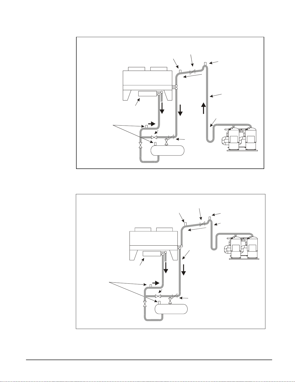
Figure 10, Condenser Above Compressor and Receiver
Check Valve
(Preferred)
Relief Valve
Purge Valve
Relief Valve
(Vent to Outdoors
Condenser
Preferred
Subcooler
Hook-up
Subcooler
To
Evap.
c
t
Pi
or to Condenser Side
of Liquid Line
Check Valve)
Receiver
Bypass
Check
Valve
Receiver
Figure 11, Condenser and Compressor on Same Level
Check Valve
(Preferred)
Relief Valve
h
Discharge Line
Loop
Purge Valve
Relief V a l v e
(Vent to Outdoors
or to Condenser Side
of Liquid Line
Check Valve)
Condenser
Preferred
Subcooler
Hook-up
Subcooler
To
Evap.
Receiver
Bypass
Receiver
i
P
Check
Valve
Check
Valve
Discharge Line
h
c
t
IOMM WGZ-1 WGZ 030A through 100A 19
Page 20
Factory-Mounted Condenser
Units with the standard water-cooled, factory-mounted condenser are provided with complete
refrigerant piping and full operating refrigerant charge at the factory.
There is a remote possibility on water-cooled units utilizing low temperature pond or river water as a
condensing medium, and if the water valves leak, that the condenser and liquid line refrigerant
temperature could drop below the equipment room temperature on the “off” cycle. This problem only
arises during periods when cold water continues to circulate through the condenser and the unit
remains off due to satisfied cooling load.
If this condition occurs:
1. Cycle the condenser pump off with the unit.
2. Check the liquid line solenoid valve for proper operation.
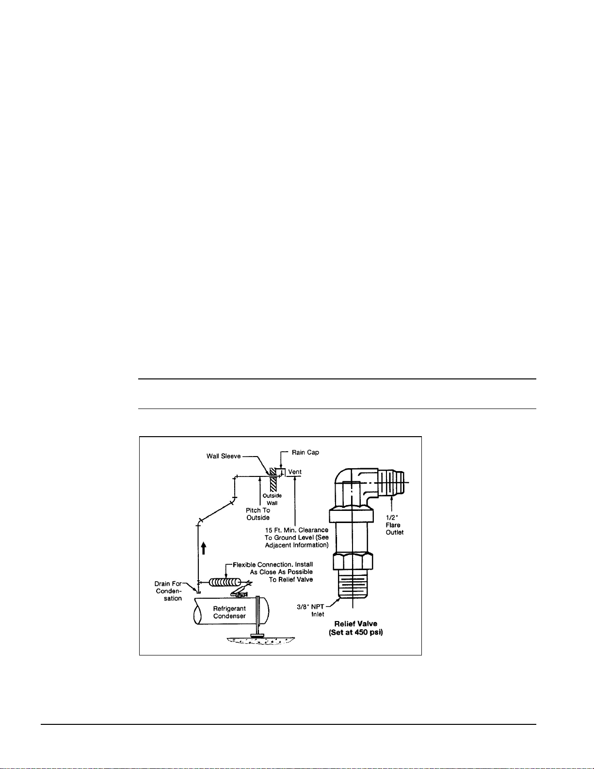
Relief Valve Piping
The ANSI/ASHRAE Standard 15, Safety Standard for Refrigeration Systems, specifies that pressure
relief valves on vessels containing Group 1 refrigerant (R-22) “shall discharge to the atmosphere at a
location not less than 15 feet (4.6 meters) above the adjoining ground level and not less than 20 feet
(6.1 meters) from any window, ventilation opening or exit in any building.” The piping must be
provided with a rain cap at the outside terminating point and with a drain at the low point on the vent
piping to prevent water buildup on the atmospheric side of the relief valve. In addition, a flexible pipe
section should be installed in the line to eliminate any piping stress on the relief valve(s).
The size of the discharge pipe from the pressure relief valve should not be less than the size of the
pressure relief outlet. When two or more vessels are piped together, the common header and piping
to the atmosphere should not be less than the sum of the area of each of the lines connected to the
header.
NOTE: Fittings should be provided to permit vent piping to be easily disconnected for
inspection or replacement of the relief valve.
Figure 12, Relief Valve Piping
20 WGZ 030A through 100A IOMM WGZ-1
Page 21
Dimensional Data
s
WGZ-AW Water-Cooled
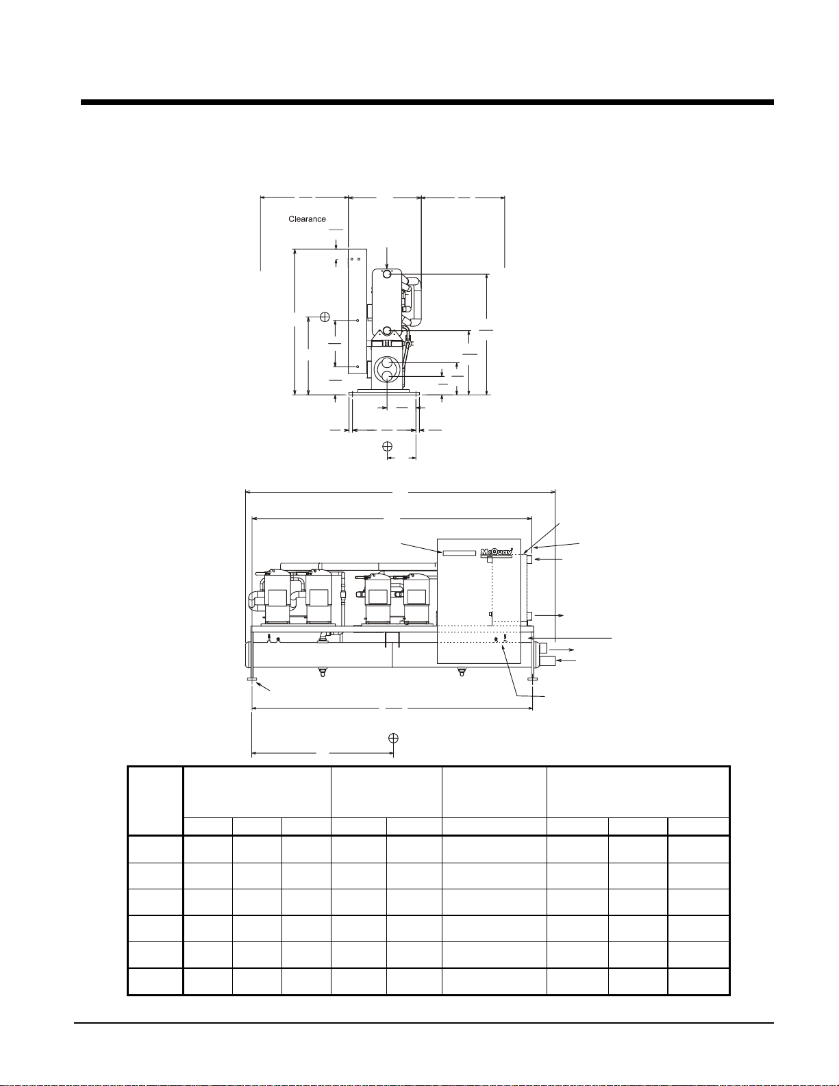
Figure 13, WGZ 030AW through WGZ 055AW
38
965
Door Swing
4.5
114
W
Evaporator
36
915
Recommended
for Servicing
H
Y
MicroTech II User Interface
(4) .875" (22 mm)
Mounting Holes
20
508
12.3
311
1.5
38
Condenser
29
711
121.4
3085
13.25
A
337
L
52.4
1331
27.8
707
14
8
354
204
1.5
38
Z
Evaporator
Control Connection
Inlet
Outlet
Power Connection
Outlet
(2) .875" (22 mm)
Inlet
Relief Valves
(1) Each End
WGZ
Model
Number
030
035
040
045
050
055
X
Maximum Overall
Dimensions
in. (mm)
Chiller Water
Connection
Victaulic, in. (mm)
Condenser Water
Connections
Victaulic, in. (mm)
Center of Gravity
in. (mm)
L W H Size A Size X Y Z
134.1
(3406)
134.1
(3406)
134.1
(3406)
134.1
(3406)
134.1
(3406)
134.1
(3406)
32
(813)
32
(813)
32
(813)
32
(813)
32
(813)
32
(813)
63.5
(1613)
63.5
(1613)
63.5
(1613)
63.5
(1613)
63.5
(1613)
63.5
(1613)
3”
(76)
3”
(76)
3”
(76)
3”
(76)
3”
(76)
3”
(76)
115.5
(2394)
116.4
(2957)
117.7
(2991)
119
(3024)
120.4
(3058)
121.1
(3075)
4”
(102)
4”
(102)
4”
(102)
4”
(102)
4”
(102)
4”
(102)
66
(1676)
66.3
(1684)
66.7
(1694)
67.1
(1704)
67.5
(1714)
66.4
(1687)
27.5
(698)
27.5
(698)
27.4
(696)
27.6
(701)
27.4
(696)
27.5
(698)
14.4
(366)
14.4
(366)
14.3
(363)
14.3
(363)
14.3
(363)
14.2
(361)
IOMM WGZ-1 WGZ 030A through 100A 21
Page 22
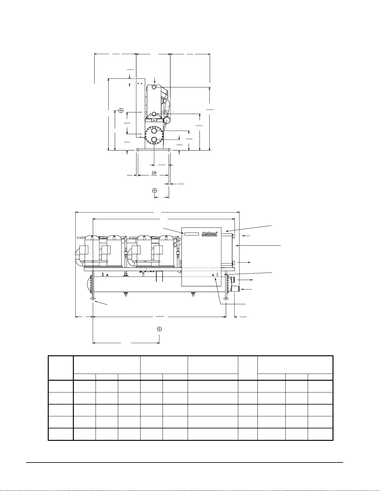
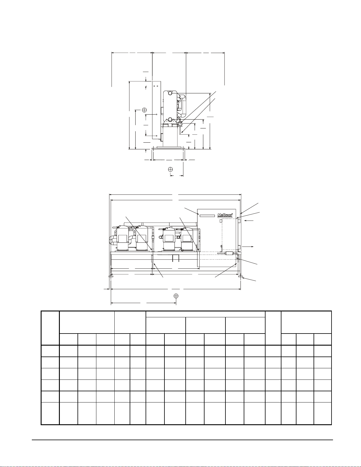
Figure 14, WGZ-060AW through WGZ-100AW
n
38
965
Door Swing
Clearance
H
4.5
114
20
508
Y
15
382
1.5
38
MicroTech II User Interface
W
Evaporator
13.25
337
737
L
Z
A
36
915
Recommended
for Servicing
18
458
9.8
248
1.5
38
33.5
852
58.1
1476
Control Connectio
Inlet
Evaporator
WGZ
Model
Number
060
070
080
090
100
Condenser
(4) .875" (22 mm)
Diameter Mounting Holes
T
X
Maximum Overall
Dimensions
in. (mm)
121.1
3075
Chiller Water
Connection
Victaulic, in. (mm)
Condenser Water
Connections
Victaulic, in. (mm)
L W H Size A Size
144.2
(3663)
146.7
(3726)
146.7
(3726)
149
(3784)
149
(3784)
32
(813)
32
(813)
32
(813)
32
(813)
32
(813)
66
(1676)
66
(1676)
66
(1676)
3
(76)
3
(76)
3
(76)
66
(1676) 3 (76)
66
(1676)
3
(76)
117.2
(2978)
118.8
(3018)
122.5
(3112)
126.6
(3216)
128.9
(3274)
5
(127)
5 (127)
5
(127)
5
(127)
5
(127)
Relief Valves
(1) Each End
7.7
196
T
11.0
(280)
12.0
(306)
12.0
(306)
15.8
(401)
15.8
9401)
Outlet
Power Connections
(2) .875" (22 mm)
Outlet
Inlet
Center of Gravity
in. (mm)
X Y Z
64.1
(1628)
63
(1600)
62.4
(1585)
62
(1575)
66.3
(1684)
31
(787)
32
(813)
32.7
(831)
33.4
(848)
33.1
(841)
13.9
(354)
13.9
(354)
13.8
(352)
13.8
(352)
13.4
(341)
22 WGZ 030A through 100A IOMM WGZ-1
Page 23
WGZ-AA Remote Condenser
Figure 15, Dimensions, WGZ 030AA – WGZ 055AA
38
965
Door Swing
Clearance
4.5
114
H
20
508
Y
12.5
318
1.5
38
MicroTech II User Interface
"G" Disch. System #2 "G" Disch. System #1
W
29
737
Recommended
for Servicing
27.8
707
24.1
613
13.8
350
1.5
38
Z
L
A
36
915
52.4
1331
"G" Disch Conn
"E" Liquid Conn
Control Connection
Evaporator
Inlet
WGZ
Model
Number
030
035
040
045
050
055
B C
D F
T
Maximum Overall
Dimensions
in. (mm)
Chiller Water
Connection
Victaulic
in. (mm)
L W H Size A
122.4
(3109)
122.4
(3109)
122.4
(3109)
122.4
(3109)
122.4
(3109)
123.4
(3134)
32
(813)
32
(813)
32
(813)
32
(813)
32
(813)
32
(813)
63.5
(1613)
63.5
(1613)
63.5
(1613)
63.5
(1613)
63.5
(1613)
63.5
(1613)
3
(76)
3
(76)
3
(76)
3
(76)
3
(76)
3
(76)
"E" Liquid System #2 "E" Liquid System #1
121.4
3085
X
Refrigerant Connections
System #1 System #2 Connection Size
Liquid F Disch. C Liquid D Disch. B Liquid E Disch.
115.5
(2394)
116.4
(2957)
117.7
(2991)
119
(3024)
120.4
(3058)
121.1
(3075)
67
(1702)
67
(1702)
67
(1702)
67
(1702)
67
(1702)
80.2
(2037)
38.2
(970)
38.2
(970)
38.2
(970)
38.2
(970)
38.2
(970)
43.4
(1102)
52
(1320)
52
(1320)
52
(1320)
52
(1320)
52
(1320)
38.6
(980)
42.9
(1090)
42.9
(1090)
42.9
(1090)
42.9
(1090)
42.9
(1090)
39.5
(1003)
.875
(22)
.875
(22)
.875
(22)
.875
(22)
.875
(22)
.875
(22)
1.125
(29)
Outlet
Power Connections
(2) - .875 (22 mm)
(4) - .875 (22 mm)
Mounting Holes
G
1.125
(29)
1.125
(29)
1.125
(29)
1.125
(29)
1.125
(29)
1.125
(29)
1.375
(35)
T
2.9
(74)
2.9
(74)
2.9
(74)
2.9
(74)
2.9
(74)
2.9
(74)
Center of Gravity
in. (mm)
X Y Z
66.7
31.2
31.3
31.5
31.7
31.9
32
14.7
(373)
14.6
(371)
14.6
(371)
14.6
(371)
14.5
(368)
14.5
(368)
(1694)
67.3
(1709)
67.9
(1725)
68.4
(1737)
69.2
(1758)
67.8
(1722)
(792)
(795)
(800)
(805)
(810)
(813)
IOMM WGZ-1 WGZ 030A through 100A 23
Page 24
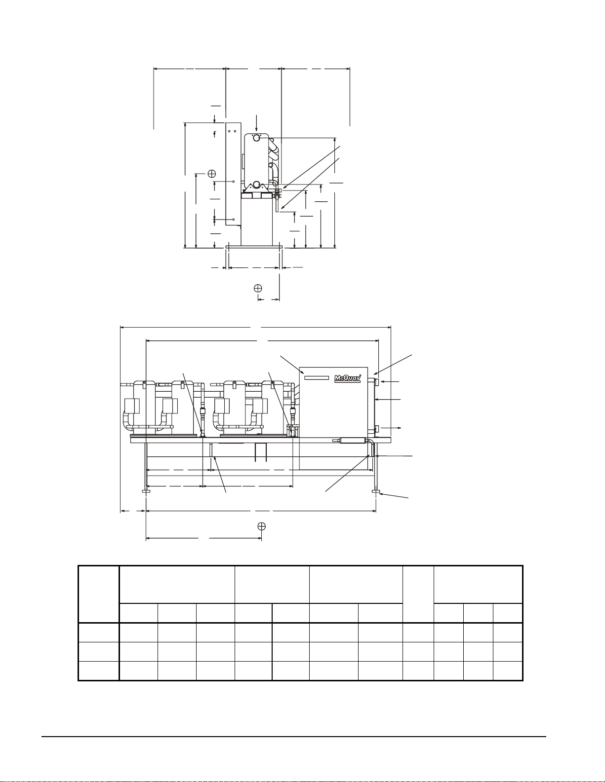
Figure 16, Dimensions WGZ 060AA – 080AA
s
38
36
965
Door Swing
Clearance
4.5
114
W
Evaporator
915
Recommended
for Servicing
"G" Disch Conn
"E" Liquid Conn
H
20
508
Y
15.1
382
1.5
38
MicroTech II User Interface
"G" Disch. System #2 "G" Disch. System #1
34.2
868
29.8
758
T
47.5
1206
29
737
L
121.1
3075
58.1
1476
33.5
852
30.3
770
19
483
1.5
38
Z
A
Control Connection
Inlet
Evaporator
Outlet
Power Connection
85.3
2166
"E" Liquid System #1"E" Liquid System #2
(2) - .875 (22mm)
(4) - .875 (22mm)
Mounting Holes
X
WGZ
MODEL
Dimensions
in. (mm)
NO.
L W H Size A
Maximum Overall
060
070
080
140
(3556)
142.5
(3620)
142.5
(3620)
32
(813)
32
(813)
32
(813)
66
(1676)
66
(1676)
66
(1676)
24 WGZ 030A through 100A IOMM WGZ-1
Evaporator Water
Connections
Victaulic
in. (mm)
3
(76)
3
(76)
3
(76)
117.2
(2978)
118.8
(3018)
122.5
(3112)
Refrigerant Connections
(OD)
in. (mm)
Liquid E Discharge
G
1.125
(29)
1.125
(29)
1.125
(29)
1.375
(35)
1.375 (35)
1.625 (41)
1.625
(41)
T
11
(280)
12
(306)
12
(306)
Center of Gravity
in. (mm)
X Y Z
64.3
(1633)
63
(1600)
64.3
(1633)
33.8
(859)
36.6
(930)
(965)
38
14.2
(362)
14.1
(359)
14.1
(359)
Page 25
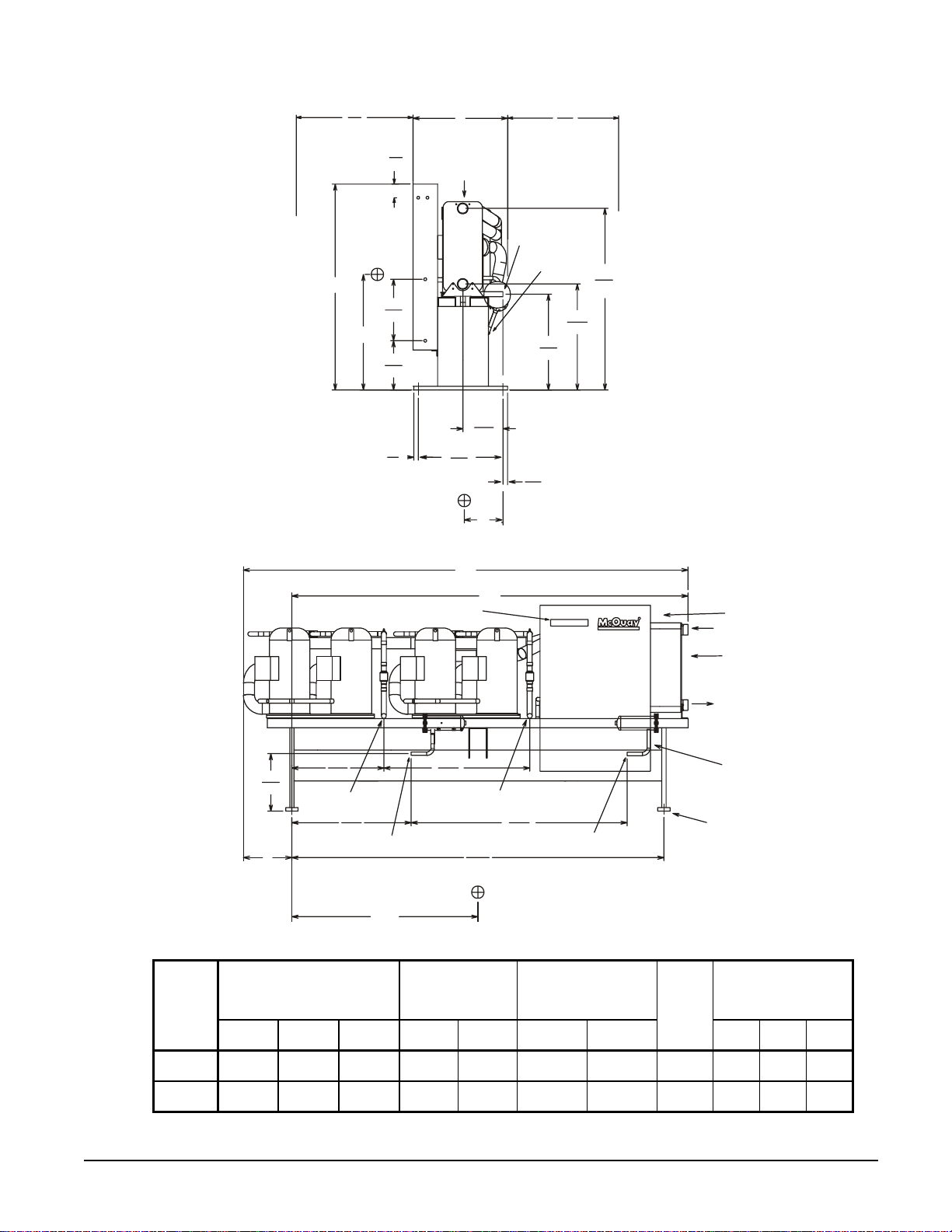
Figure 17, Dimensions WGZ 090AA – 100AA
n
8
3
965
Door Swing
Clearance
H
Y
4.5
114
20
508
16
407
1.5
38
W
Evaporator
13.25
377
29
737
"G" Discharge Conn
"E" Liquid Conn
1.5
38
Z
915
Recommended
for Servicing
31.2
792
36
59.1
1501
34.5
877
WGZ
MODEL
NO.
090
100
L
17.7
450
T
MicroTech II User Interface
29.9
760
38.8
986
"E" Liquid Conn System 2
X
47.5
1206
A
"G" Discharge Conn System 1"G" Discharge Conn System 2
121.1
3075
Maximum Overall
Dimensions
in. (mm)
L W H Size A
144.75
(3667)
144.75
(3667)
32
(813)
32
(813)
66
(1676)
66
(1676)
Evaporator Water
Connections
(Victaulic)
in. (mm)
3
(76)
3
(76)
126.6
(3216)
128.9
(3274)
70.3
1785
"E" Liquid Conn System 1
Refrigerant Connections
(OD)
Liquid E Discharge
G
1.125
(29)
1.125
(29)
1.625
(41)
1.625
(41)
Control Connectio
Inlet
Evaporator
Outlet
Power Connections
(2) .875" (22 mm)
(4) .875" (22 mm)
Diameter Mounting Holes
Center of Gravity
in. (mm)
T
15.8
(401)
15.8
(401)
X Y Z
63.1
(1603)
67.5
(1715)
38.4
(975)
38.6
(980)
14.1
(359)
13.6
(346)
IOMM WGZ-1 WGZ 030A through 100A 25
Page 26
Physical Data
AW Water-Cooled
Table 8, WGZ-030AW - WGZ-055AW
WGZ UNIT SIZE 030 035 040 045 050 055
Unit capacity @ ARI condi tions
tons, (kW) (1)
No. Circuits 2 2 2 2 2 2
COMPRESSORS
Nominal Horsepower 7.5 9 9 9 10 10 13 10 13 13 13 16
Number (2) 2 2 2 2 2 2 2 2 2 2 2 2
Unloading Steps 27 / 50 / 77 25 / 50 / 75 25 / 50 / 75 28 / 50 / 78 25 / 50 / 75 27 / 50 / 77
Oil Charge per Compressor oz., (l ) 140 (4.1) 140 (4.1) 140 (4.1) 140 (4.1) 140 (4.1) 140 (4.1)
CONDENSER
Number 1 1 1 1 1 1
No. Refrigerant Circuits 2 2 2 2 2 2
Diameter, in., (mm) 10 (254) 10 (254) 10 (254) 10 (254) 10 (254) 10 (254)
Tube Length, in., (mm ) 120 (3048) 120 (3048) 120 (3048) 120 (3048) 120 (3048) 120 (3048)
Design W.P. psig, (kPa):
Refrigerant Side 450 (3102) 450 (3102) 450 (3102) 450 (3102) 450 (3102) 450 (3102)
Water Side 232 (1599) 232 (1599) 232 (1599) 232 (1599) 232 (1599) 232 (1599)
No. of Passes 2 2 2 2 2 2
Pump-Out Capacity, l b., (kg) (3) 279 (126.6) 273 (123.8) 260 (117.9) 253 (114.8) 240 (108.9) 234 (106.1)
Connections:
Water In & Out , in, (mm) victaul i c 4 (102) 4 (102) 4 (102) 4 (102) 4 (102) 4 (102)
Relief Valve, Flare In., (mm) ½ (12.7) ½ (12.7) ½ (12.7) ½ (12. 7) ½ (12.7) ½ (12.7)
Purge Valve, Flare In., (m m) ½ (12.7) ½ (12.7) ½ (12.7) ½ (12.7) ½ (12.7) ½ (12. 7)
Vent & Drain, in. (mm) FPT ½ (12.7) ½ (12.7) ½ (12.7) ½ (12.7) ½ (12.7) ½ (12.7)
Liquid Subcooling Integral Integral Integral Integral Integral Integral
EVAPORATOR
Number 1 1 1 1 1 1
No. Refrigerant Circuits 2 2 2 2 2 2
Water Volume, gallons, (l) 3.9 (14. 7) 4.3 (16.4) 5 (18.9) 5.7 (21.4) 6.3 (23.9) 7.2 (27.3)
Refrig. Side D.W.P., psig, (kP a) 450 (3102) 450 (3102) 450 (3102) 450 (3102) 450 (3102) 450 (3102)
Water Side D.W.P., psi g, (kPa) 363 (2503) 363 (2503) 363 (2503) 363 (2503) 363 (2503) 363 (2503)
Water Connecti ons :
Inlet & Outlet, in. , (mm) victaulic 3 (76) 3 (76) 3 (76) 3 (76) 3 (76) 3 (76)
Drain & Vent (NPT INT.) Field Field Field Field Field Field
UNIT DIMENSIONS
Length In., (mm) 134.1 (3406) 134.1 (3406) 134.1 (3406) 134.1 (3406) 134.1 (3406) 134.1 (3406)
Width In., (mm) 32 (813) 32 (813) 32 (813) 32 (813) 32 (813) 32 (813)
Height In., (mm) 63.5 (1613) 63.5 (1613) 63.5 (1613) 63.5 (1613) 63.5 (1613) 63.5 (1613)
UNIT WEIGHTS
Operating Weight, l b., (kg) 2692 (1219) 2760 (1250) 2866 (1298) 2966 (1344) 3058 (1385) 3213 (1455)
Shipping Weight, lb., (kg) 2551 (1157) 2606 (1182) 2684 (1217) 2763 (1253) 2828 (1283) 2973 (1349)
Operating Charge, lb., (kg) R-22 100 (45.4) 99 (44.9) 94 (42.6) 92 (41.7) 88 (39.9) 89 (40.4)
Notes:
1. Certified in accordance with ARI Standard 550/590-98.
2. All units have two compressors per circuit in parallel.
3. 80% full R-22 at 90°F (32°C) per unit.
31.6 (111.1) 34.9 (122.7) 40.1 (141) 44.2 (155) 48.6 (171) 54.3 (191)
26 WGZ 030A through 100A IOMM WGZ-1
Page 27

Table 9, WGZ-060AW - WGZ-100AW
WGZ UNIT SIZE 060 070 080 090 100
Unit capacity @ ARI condi tions
tons, (kW) (1)
No. Circuits 2 2 2 2 2
COMPRESSORS
Nominal Horsepower 16 16 16 20 20 20 20 25 25 25
Number (2) 2 2 2 2 2 2 2 2 2 2
Unloading Steps 25 / 50 / 75 28 / 50 / 78 25 / 50 / 75 27 / 50 / 77 25 / 50 / 75
Oil Charge, per compressor oz. (l) 140 (4.1) 140 (4.1) 148 (4.3) 148 (4.3) 200 (5.9) 200 (5.9 200 (5.9
CONDENSER
Number 1 1 1 1 1
No. Refrigerant Circuits 2 2 2 2 2
Diameter, in. (m m) 14 (356) 14 (356) 14 (356) 14 (356) 14 (356)
Tube Length, in. (mm) 120 (3048) 120 (3048) 120 (3048) 120 (3048) 120 (3048)
Design W.P., psig (kPa):
Refrigerant Side 450 (3102) 450 (3102) 450 (3102) 450 (3102) 450 (3102)
Water Side 232 (1599) 232 (1599) 232 (1599) 232 (1599) 232 (1599)
No. of Passes 2 2 2 2 2
Pump-Out Capacity
lb., (kg) (3)
Connections:
Water In & Out , i n., (mm) (4) 5 (127) 5 (127) 5 (127) 5 (127) 5 (127)
Relief Valve, Flare in., (mm) ½ (12.7) ½ (12.7) ½ (12.7) ½ (12.7) ½ (12.7)
Purge Valve, Flare in. (mm) ½ (12.7) ½ (12.7) ½ (12.7) ½ (12.7) ½ (12.7)
Vent & Drain, in. (mm) FPT ½ (12.7) ½ (12.7) ½ (12.7) ½ (12.7) ½ (12.7)
Liquid Subcooling Integral Integral Integral Integral Integral
EVAPORATOR
Number 1 1 1 1 1
No. Refrigerant Circuits 2 2 2 2 2
Water Volume, gallons (l) 8.1 (30.7) 9.2 (34.9) 10.8 (40.7) 12.8 (48.3) 13.9 (52.5)
Refrigerant Side D.W.P., psig,
(kPa)
Water Side D.W.P., psi g, (kPa) 363 (2503) 363 (2503) 363 (2503) 363 (2503) 363 (2503)
Water Connecti ons:
In & Out, in. (mm) victaulic 3 (76) 3 (76) 3 (76) 3 (76) 3 (76)
Drain & Vent Field Field Field Field Field
UNIT DIMENSIONS
Length, in. (mm) 144.2 (3663) 146.7 (3726) 146.7 (3726) 149 (3784) 149 (3784)
Width, in. (mm) 32 (813) 32 (813) 32 (813) 32 (813) 32 (813)
Height, in. (mm ) 66 (1676) 66 (1676) 66 (1676) 66 (1676) 66 (1676)
UNIT WEIGHTS
Operating Weight, l b. (kg) 3809 (1725) 4025 (1823) 4289 (1943) 4484 (2031) 4627 (2096)
Shipping Weight, lb. (kg) 3500 (1588) 3716 (1686) 3947 (1790) 4094 (1857) 4197 (1904)
R-22 Ref. Charge, lb. (kg) 173 (78.5) 167 (75.7) 163 (73.9) 151 (68.5) 151 (68.5)
Notes:
1. Certified in accordance with ARI Standard 550/590-98.
2. All units have two compressors per circuit in parallel.
3. 80% full R-22 at 90°F (32°C) per unit.
4. Victaulic connections.
60.3 (212) 68.0 (239) 75.6 (266) 84.4 (297) 93.7 (330)
481 (218.2) 462 (209.6) 449 (203.7) 429 (194.6) 409 (185.5)
450 (3102) 450 (3102) 450 (3102) 450 (3102) 450 (3102)
IOMM WGZ-1 WGZ 030A through 100A 27
Page 28

AA Remote Condenser
Table 10, WGZ-030AA - WGZ-055AA
WGZ UNIT SIZE 030 035 040 045 050 055
Cap @ 44°F LWT , 125°F SDT
tons, (kW)
No. Circuits 2 2 2 2 2 2
COMPRESSORS
Nominal Horsepower 7.5 9 9 9 10 10 13 10 13 13 13 16
Number (2) 2 2 2 2 2 2 2 2 2 2 2 2
Unloading Steps 27 / 50 / 77 25 / 50 / 75 25 / 50 / 75 28 / 50 / 78 25 / 50 / 75 27 / 50 / 77
Oil Charge, per compressor oz. (l) 140 (4.1) 140 (4.1) 140 (4.1) 140 (4.1) 140 (4.1) 140 (4.1)
Discharge Valve In., (mm) 1.125 (28) 1.125 (28) 1.125 (28) 1.125 (28) 1.125 (28)
EVAPORATOR
No. Refrigerant Circuits 2 2 2 2 2 2
Water Volume, gallons, (l) 3.9 (14.7) 4.3 (16.4) 5 (18.9) 5.7 (21.4) 6.3 (23.9) 7.2 (27.3)
Refrig. Side D.W.P. psig (kPa) 450 (3102) 450 (3102) 450 (3102) 450 (3102) 450 (3102) 450 (3102)
Water Side D.W.P. psig (k Pa) 363 (2503) 363 (2503) 363 (2503) 363 (2503) 363 (2503) 363 (2503)
Water Connecti ons :
Inlet & Outlet, in. , (mm) (1) 3 (76) 3 (76) 3 (76) 3 (76) 3 (76) 3 (76)
Drain & Vent Field Field Field Field Field Field
UNIT DIMENSIONS
Length In., (mm) 122.4 (3109) 122.4 (3109) 122.4 (3109) 122.4 (3109) 122. 4 (3109) 123.4 (3134)
Width In., (mm) 32 (813) 32 (813) 32 (813) 32 (813) 32 (813) 32 (813)
Height In., (mm) 63.5 (1613) 63.5 (1613) 63.5 (1613) 63.5 (1613) 63.5 (1613) 63.5 (1613)
UNIT WEIGHTS
Operating Weight, l b. (kg) 2162 (981) 2204 (1000) 2257 (1024) 2329 (1056) 2370 (1075) 2505 (1136)
Shipping Weight, lb. (kg) 2134 (968) 2172 (985) 2219 (1007) 2281 (1035) 2315 (1050) 2452 (1112)
Holding Charge, lb. (kg) R-22 6.0 (2.7) 6.1 (2.8) 6.4 (2.9) 6.6 (3) 7.0 (3.2) 9.7 (4.4)
29 (103) 31.6 (112) 36.6 (130) 40.7 (144) 44.7 (158) 49.8 (177)
1.125 (28)
1.375 (35)
Table 11, WGZ-060AA - WGZ-100AA
WHR UNIT SIZE 060 070 080 090 100
Cap @ 44°F LWT , 125°F
SDT tons, (kW)
No. Circuits 2 2 2 2 2
COMPRESSORS
Nominal Horsepower 16 16 16 20 20 20 20 25 25 25
Number (3) 2 2 2 2 2 2 2 2 2 2
Unloading Steps 25 / 50 / 75 28 / 50 / 78 25 / 50 / 75 27 / 50 / 77 25 / 50 / 75
Oil Charge oz 140 (4.1) 140 (4.1) 148 (4.3) 148 (4.3) 148 (4.3) 148 (4.3) 200 (5.9) 200 (5.9) 200 (5.9)
EVAPORATOR
No. Refrigerant Circuits 2 2 2 2 2
Water Volume, gallons (l) 8.1 (30. 7 9.2 (34.9) 10.8 (40.7) 12.8 (48. 3) 13.9 (52.5)
Refrigerant Side D.W.P., psig
(kPa)
Water Side D.W.P., psig
(kPa)
Water Connecti ons:
Inlet & Outlet, in. (mm) (1) 3 (76) 3 (76) 3 (76) 3 (76) 3 (76)
Drain & Vent Field Fiel d Field Field Fi el d
UNIT DIMENSIONS
Length, in. (mm) 140 (3556) 142.5 (3620) 142.5 (3620) 144.75 (3677) 144.75 (3677)
Width, in. (mm) 32 (813) 32 (813) 32 (813) 32 (813) 32 (813)
Height, in. (mm ) 66 (1676) 66 (1676) 66 (1676) 66 (1676) 66 (1676)
UNIT WEIGHTS
Operating Weight, l b. (kg) 2771 (1257) 2942 (1334) 3154 (1431) 3271 (1484) 3346 (1518)
Shipping Weight, lb. (kg) 2701 (1225) 2871 (1302) 3071 (1393) 3172 (1439) 3238 (1469)
Holding Charge, lb. (kg) R-22 10.0 (4.5) 10.5 (4.7) 11.1 (5) 11.8 (5.4) 12.3 (5.6)
Notes:
1. Victaulic connections.
2. All units have two compressors per circuit in parallel.
54.9 (195) 62.1 (220) 69.5 (246) 77.9 (276) 85. 9 (305)
450 (3102) 450 (3102) 450 (3102) 450 (3102) 450 (3102)
363 (2503) 363 (2503) 363 (2503) 363 (2503) 363 (2503)
28 WGZ 030A through 100A IOMM WGZ-1
Page 29

Operating Limits
• Maximum allowable condenser water pressure is 232 psig (1599 kPa).
• Maximum allowable cooler water pressure is 363 psig (2509 kPa).
• Maximum design saturated discharge temperature is 140°F (60°C).
• Maximum allowable water temperature to cooler in a non-operating cycle is 100°F (37.8°C).
Maximum entering water temperature for operating cycle is 90°F (32.2°C) (during system
changeover from heating to cooling cycle).
• Minimum leaving water temperature from the cooler without freeze protection is 40°F (4.4°C).
• Minimum entering tower condenser water temperature is 60°F (15.6°C).
Components
Figure 18, Compressor Locations
Evaporator and
423
1
Evaporator
Condenser
Connections
Circuit 2 Circuit 1
Control Panel
Table 12, Major Components
Unit
Size
030 ZR90K3 ZR90K3 ZR11M3 ZR11M3 AC250-70DQ C1007-068 OVE-20-CP100 OVE-20-CP100
035 ZR11M3 ZR11M3 ZR11M3 ZR11M3 AC250-78DQ C1007-076 OVE-20-CP100 OVE-20-CP100
040 ZR12M3 ZR12M3 ZR12M3 ZR12M3 AC250-90DQ C1007-084 OVE-20-CP100 OVE-20-CP100
045 ZR12M3 ZR12M3 ZR16M3 ZR16M3 AC250-102DQ C1207-092 OVE-30-CP100 OVE-30-CP100
050 ZR16M3 ZR16M3 ZR16M3 ZR16M3 AC250-114DQ C1207-108 OVE-30-CP100 OVE-30-CP100
055 ZR16M3 ZR16M3 ZR19M3 ZR19M3 AC250-130DQ C1407-120 OVE-30-CP100 Y929-VCP100
060 ZR19M3 ZR19M3 ZR19M3 ZR19M3 AC250-146DQ C1607-136 Y929-VCP100 Y929-VCP100
070 ZR19M3 ZR19M3 ZR250KC ZR250KC AC250-166DQ C1010-092 Y929-VCP100 Y929-VCP100
080 ZR250KC ZR250KC ZR250KC ZR250KC AC250-194DQ C1210-104 Y929-VCP100 Y929-VCP100
090 ZR250KC ZR250KC ZR300KC ZR300KC AC250-230DQ C1210-112 OVE-55-CP100 OVE-55-CP100
100 ZR300KC ZR300KC ZR300KC ZR300KC AC250-250DQ C1210-128 OVE-55-CP100 OVE-55-CP100
System #1 System #2 Expansion Valve
Comp. #1 Com p . #3 Comp. #2 Comp. #4
Evap.
Vessel
Size
Cond.
Vessel
Size
System #1 System #2
IOMM WGZ-1 WGZ 030A through 100A 29
Page 30

Wiring
Field Wiring, Power
The WGZ “A” vintage chillers are built standard with compressor contractors and power terminal
block, desi gned for single po wer suppl y to the unit. Optional power connec tions includ e a non-fused
disconnect switch mounted in the control box or multi-point power connection.
A factory installed control circuit transformer is standard. Optionally, a field-installed control power
source can be wired to the unit.
Circuit breakers for backup compressor short circuit protection are standard on all units.
Wiring and conduit selections must comply with the National Electrical Code and/or local
requirements.
An open fuse indicates a short, ground, or overload. Before replacing a fuse or restarting a
compressor, the trouble must be found and corrected. Tables in the Electrical Data section (page 32)
give specific information on recommended wire sizes.
Unit power inlet wiri ng must ente r t he c o ntr o l b o x ( ri ght sid e) thro ugh a pat ch pl at e pr o vid e d for fiel d
terminating conduit. (Refer to control panel dimension drawings for general location of power inlet
and components.)
NOTE: Use only copper conductors in main terminal block. Terminations are sized for
copper only.
Field Wiring, Control
A factory-mounted control transformer is provided to supply the correct control circuit voltage.
The transformer power leads are connected to the power block PB1 or disconnect switch DS1.
Interlock Wiring, Condenser Pump Starter or Air Cooled Condenser Fan Starter
Provisions are made for interlocking a condenser pump starter, tower fans, a tower bypass valve, or
up to eight air-cooled condenser fan contactors to be controlled by the MicroTech II unit controller.
Condenser fan operation can also be controlled by pressure switches supplied with the condenser.
Coil voltage must be 115 volts with a maximum of 20 VA.
An evaporator and condenser (water-cooled units only) flow switch is necessary on all units. It is also
advisable to wire a chilled water pump interlock in series with the flow switch for additional freeze
protection.
Ambient A ir Sensor
Units with a remote air-cooled condenser will have an outdoor air sensor furnished with the unit,
inside the control panel and wired to the correct terminals. It must be installed outdoors in a location
that will give the true outdoor temperature that the condenser coils will see. Splicing of the sensor
lead may be required. The sensor must be installed for the unit to operate.
30 WGZ 030A through 100A IOMM WGZ-1
Page 31

Unit Configuration
The chiller unit has two refrigerant circuits, two tandem scroll compressors (total of four), a single
two-circuited brazed plate evaporator, a single two-circuited water-cooled condenser, interconnecting
refrigerant piping and a control panel with associated sensors and transducers.
Figure 19, Schematic Piping Diagram (One of Two Circuits)
Chilled
Water
LWT
Evaporator
S
Legend:
T
T
Temperature Sensor
P
T
Pressure Transducer
P
Pressure (High Pressure Cutout)
1
T
T
P
CV
Condenser
S
F-D
S
T
SP
1
Comp
#1
Relief Valve
Schrader Fitting
Thermal Expansion Valve
Comp
#2
S
Condenser
Water
T
Temperataure Sensor, Leaving
LWT
Chilled Water Control
S
Solenoid Valve
F-D
Filter-Drier
Sight Glass / Moisture Indicator
CV
Charging Valve
Angle Valve
Ball Valve
IOMM WGZ-1 WGZ 030A through 100A 31
Page 32

Electrical Data
Table 13, Compressor Amp Draw, WGZ 030 - WGZ 100
WGZ
Unit
Size
030
035
040
045
050
055
060
070
080
090
100
NOTE:
1. Compressor RLA values are for wire sizing purposes only and do not reflect normal operating current draw.
Voltage
3-Phase
208 23.7 29.9 189 232
230 23.7 29.9 189 232
460 12.5 15.3 99 125
575
208 29.9 29.9 232 232
230 29.9 29.9 232 232
460 15.3 15.3 125 125
575
208 33.6 33.6 255 255
230 33.6 33.6 255 255
460 16.5 16.5 127 127
575
208 33.6 41.0 255 350
230 33.6 41.0 255 350
460 16.5 21.8 127 158
575
208 41.0 41.0 350 350
230 41.0 41.0 350 350
460 21.8 21.8 158 158
575
208 41.0 52.6 350 425
230 41.0 52.6 350 425
460 21.8 23.7 158 187
575
208 52.6 52.6 425 425
230 52.6 52.6 425 425
460 23.7 23.7 187 187
575
208 52.6 70.0 425 448
230 52.6 70.0 425 448
460 23.7 35.0 187 225
575
208 70.0 70.0 448 448
230 70.0 70.0 448 448
460 35.0 35.0 225 225
575
208 70.0 79.0 448 500
230 70.0 79.0 448 500
460 35.0 38.5 225 250
575
208 79.0 79.0 500 500
230 79.0 79.0 500 500
460 38.5 38.5 250 250
575
Freq
(Hz)
60
60
60
60
60
60
60
60
60
60
60
Rated Load Amps (1) Locked Rotor Amps (2)
Per compressor
(2 / circuit)
Circuit 1 Circuit 2 Circuit 1 Circuit 2
9.1 11.6 74 100
11.6 11.6 100 100
13.7 13.7 100 100
13.7 17.3 100 125
17.3 17.3 125 125
17.3 21.7 125 148
21.7 21.7 148 148
21.7 28.0 148 180
28.0 28.0 180 180
28.0 29.0 180 198
29.0 29.0 198 198
Across-The-Line
Start
32 WGZ 030A through 100A IOMM WGZ-1
Page 33

Table 14, Wire Sizing Amps, WGZ 030 - WGZ 100
WGZ
Unit
Size
Voltage
3-Phase
Freq.
(Hz)
Minimum Circuit Ampacity (MCA) (1)
Single Point
Power
Supply(2)
Multiple Point Power
Supply(3)
Circuit 1 Circuit 2
208 115 54 68
030
230 115 54 68
460 60 29 35
575
60
45 21 27
208 128 68 68
035
230 128 68 68
460 66 35 35
575
60
50 27 27
208 143 76 76
040
230 143 76 76
460 71 38 38
575
60
59 31 31
208 160 76 93
045
230 160 76 93
460 83 38 50
575
60
67 31 39
208 175 93 93
050
230 175 93 93
460 93 50 50
575
60
74 39 39
208 201 93 119
055
230 201 93 119
460 97 50 54
575
60
84 39 49
208 224 119 119
060
230 224 119 119
460 101 54 54
575
60
93 49 49
208 263 119 158
070
230 263 119 158
460 127 54 79
575
60
104 49 63
208 298 158 158
080
230 298 158 158
460 149 79 79
575
60
119 63 63
208 318 158 178
090
230 318 158 178
460 157 79 87
575
60
122 63 66
208 336 178 178
100
NOTES:
1. Unit wire sizing amps are equal to 125% of the largest compressor-motor RLA, plus 100% of RLA of all other loads in the
circuit including control transformer.
2. Single point power supply requires a single fused disconnect to supply electrical power to the unit.
3. Multiple point power supply requires two independent power circuits with separate fused disconnects. (Two compressor
circuits and control circuit will be wired to Circuit #1 from the factory).
230 336 178 178
460 164 87 87
575
60
124 66 66
IOMM WGZ-1 WGZ 030A through 100A 33
Page 34

Table 15, Fuse Sizing, WGZ 030 - WGZ 100
WGZ
Unit
Size
Voltage
3-Phase
Freq.
(Hz)
208 125 60 80 125 70 90
030
230 125 60 80 125 70 90
460 70 35 40 70 40 45
60
575
208 150 80 80 150 90 90
035
230 150 80 80 150 90 90
460 70 40 40 80 45 45
60
575
208 175 90 90 175 100 100
040
230 175 90 90 175 100 100
460 80 45 45 80 50 50
60
575
208 175 90 110 200 100 125
045
230 175 90 110 200 100 125
460 90 45 60 100 50 70
60
575
208 200 110 110 200 125 125
050
230 200 110 110 200 125 125
460 100 60 60 110 70 70
60
575
208 225 110 150 250 125 150
055
230 225 110 150 250 125 150
460 110 60 60 110 70 70
60
575
208 250 150 150 250 150 150
060
230 250 150 150 250 150 150
460 110 60 60 110 70 70
60
575
208 300 150 200 300 150 225
070
230 300 150 200 300 150 225
460 150 60 100 150 70 110
60
575
208 350 200 200 350 225 225
080
230 350 200 200 350 225 225
460 175 100 100 175 110 110
60
575
208 350 200 225 350 225 250
090
230 350 200 225 350 225 250
460 175 100 110 175 110 125
60
575
208 400 225 225 400 250 250
100
230 400 225 225 400 250 250
460 200 110 110 200 125 125
60
575
NOTES:
1. "Recommended Fuse Size" is selected at approximately 150% of the largest compressor RLA, plus 100% of all other circuit load.
2. "Maximum Fuse Size" is selected at approximately 225% of the largest compressor RLA, plus 100% of all other loads.
Recommended Fuse Size(1) Maximum Fuse S i ze(2)
Single Point Multiple Point Single Point Multiple Point
Total Unit Circuit #1 Circuit #2 Total Unit Ci rcuit #1 Circuit #2
50 25 30 50 25 35
60 30 30 60 35 35
70 45 45 70 40 40
80 45 50 80 40 50
80 50 50 90 50 50
90 50 60 100 50 70
100 60 60 100 70 70
125 60 80 125 70 90
125 80 80 125 90 90
150 80 80 150 90 90
150 80 80 150 90 90
34 WGZ 030A through 100A IOMM WGZ-1
Page 35

Table 16, Wire Sizing, WGZ 030 - WGZ 100
WGZ
Unit
Size
030
035
040
045
050
055
060
070
080
090
100
Voltage
3-Phase
Freq.
(Hz)
208 3 1 GA 3 6 GA 3 4 GA
230 3 1 GA 3 6 GA 3 4 GA
460 3 6 GA 3 10 GA 3 8 GA
575
208 3 1/0 3 4 GA 3 4 GA
230 3 1/0 3 4 GA 3 4 GA
460 3 4 GA 3 8 GA 3 8 GA
575
208 3 1/0 3 3 GA 3 3 GA
230 3 1/0 3 3 GA 3 3 GA
460 3 4 GA 3 8 GA 3 8 GA
575
208 3 2/0 3 3 GA 3 3 GA
230 3 2/0 3 3 GA 3 3 GA
460 3 4 GA 3 8 GA 3 6 GA
575
208 3 3/0 3 3 GA 3 3 GA
230 3 3/0 3 3 GA 3 3 GA
460 3 3 GA 3 6 GA 3 6 GA
575
208 3 4/0 3 3 GA 3 1 GA
230 3 4/0 3 3 GA 3 1 GA
460 3 3 GA 3 6 GA 3 6 GA
575
208 3 4/0 3 1 GA 3 1 GA
230 3 4/0 3 1 GA 3 1 GA
460 3 2 GA 3 6 GA 3 6 GA
575
208 3 300 kcmil 3 1 GA 3 2/0
230 3 300 kcmil 3 1 GA 3 2/0
460 3 1 GA 3 6 GA 3 4 GA
575
208 3 350 kcmil 3 2/0 3 2/0
230 3 350 kcmil 3 2/0 3 2/0
460 3 1/0 3 4 GA 3 4 GA
575
208 3 400 kcmil 3 2/0 3 3/0
230 3 400 kcmil 3 2/0 3 3/0
460 3 2/0 3 4 GA 3 3 GA
575
208 3 500 kcmil 3 3/0 3 3/0
230 3 500 kcmil 3 3/0 3 3/0
460 3 2/0 3 3 GA 3 3 GA
575
60
60
60
60
60
60
60
60
60
60
60
Single Point Multiple Point
Unit Circuit #1 Circuit #2
Number Wire Size Number Wire Size Number Wire Size
3 8 GA 3 10 GA 3 8 GA
3 6 GA 3 8 GA 3 8 GA
3 6 GA 3 10 GA 3 8 GA
3 4 GA 3 8 GA 3 8 GA
3 4 GA 3 8 GA 3 8 GA
3 4 GA 3 8 GA 3 8 GA
3 3 GA 3 8 GA 3 8 GA
3 2 GA 3 8 GA 3 6 GA
3 1 GA 3 6 GA 3 6 GA
3 1 GA 3 6 GA 3 4 GA
3 1 GA 3 4 GA 3 4 GA
IOMM WGZ-1 WGZ 030A through 100A 35
Page 36

Table 17, Single Point Connection Sizing, WGZ 030 - WGZ 100
WGZ
Unit
Size
Voltage
3-Phase
Freq.
(Hz)
Power Block Dis connect Switch
Size (1) Connection (3) S i ze (2) Connection (3)
208 175 14 GA – 2/0 200 6GA – 300 kcmil
030
230 175 14 GA – 2/0 200 6GA – 300 kcmil
460 175 14 GA – 2/0 175 6GA – 300 kcmil
575
60
175 14 GA – 2/0 175 6GA – 300 kcmil
208 175 14 GA – 2/0 200 6GA – 300 kcmil
035
230 175 14 GA – 2/0 200 6GA – 300 kcmil
460 175 14 GA – 2/0 175 6GA – 300 kcmil
575
60
175 14 GA – 2/0 175 6GA – 300 kcmil
208 175 14 GA – 2/0 400 2GA – 600 kcmil
040
230 175 14 GA – 2/0 400 2GA – 600 kcmil
460 175 14 GA – 2/0 175 6GA – 300 kcmil
575
60
175 14 GA – 2/0 175 6GA – 300 kcmil
208 335 6 GA – 400 kcmil 400 2GA – 600 kcmil
045
230 335 6 GA – 400 kcmil 400 2GA – 600 kcmil
460 175 14 GA – 2/0 200 6GA – 300 kcmil
575
60
175 14 GA – 2/0 175 6GA – 300 kcmil
208 335 6 GA – 400 kcmil 400 2GA – 600 kcmil
050
230 335 6 GA – 400 kcmil 400 2GA – 600 kcmil
460 175 14 GA – 2/0 200 6GA – 300 kcmil
575
60
175 14 GA – 2/0 175 6GA – 300 kcmil
208 335 6 GA – 400 kcmil 400 2GA – 600 kcmil
055
230 335 6 GA – 400 kcmil 400 2GA – 600 kcmil
460
60
175 14 GA – 2/0 200 6GA – 300 kcmil
575 175 14 GA – 2/0 200 6GA – 300 kcmil
208 335 6 GA – 400 kcmil 400 2GA – 600 kcmil
060
230 335 6 GA – 400 kcmil 400 2GA – 600 kcmil
460 175 14 GA – 2/0 200 6GA – 300 kcmil
575
60
175 14 GA – 2/0 200 6GA – 300 kcmil
208 335 6 GA – 400 kcmil 600 (2) 2GA – 600 kcmil
070
230 335 6 GA – 400 kcmil 600 (2) 2GA – 600 kcmil
460 175 14 GA – 2/0 200 6GA – 300 kcmil
575
60
175 14 GA – 2/0 200 6GA – 300 kcmil
208 760 2 GA – 500 kcmil 600 (2) 2GA – 600 kcmil
080
230 760 2 GA – 500 kcmil 600 (2) 2GA – 600 kcmil
460 335 6 GA – 400 kcmil 200 6GA – 300 kcmil
575
60
335 6 GA – 400 kcmil 200 6GA – 300 kcmil
208 760 2 GA – 500 kcmil 600 (2) 2GA – 600 kcmil
090
230 760 2 GA – 500 kcmil 600 (2) 2GA – 600 kcmil
460 335 6 GA – 400 kcmil 400 2GA – 600 kcmil
575
60
335 6 GA – 400 kcmil 200 6GA – 300 kcmil
208 760 2 GA – 500 kcmil 600 (2) 2GA – 600 kcmil
100
NOTES:
1. "Size" is the maximum amperage rating for the terminals or the main electrical device.
2. "Size" is the disconnect part number and not the amperage rating for the terminals or the main electrical device.
3. "Connection" is the range of wire sizes that the terminals on the electrical device will accept.
230 760 2 GA – 500 kcmil 600 (2) 2GA – 600 kcmil
460 335 6 GA – 400 kcmil 400 2GA – 600 kcmil
575
60
335 6 GA – 400 kcmil 200 6GA – 300 kcmil
Single Point
36 WGZ 030A through 100A IOMM WGZ-1
Page 37

Table 18, Multiple Point Connection Sizing, WGZ 030 - WGZ 100
WGZ
Unit
Size
Voltage
3-Phase
Freq.
(Hz)
Size (1) Connec tion (3) Size (2) Connection (3) Size (1) Connect i on (3) Size (2) Connection (3)
208 175 14 GA – 2/0 100 8 GA – 2/0 175 14 GA – 2/0 100 8 GA – 2/0
230 175 14 GA – 2/0 100 8 GA – 2/0 175 14 GA – 2/0 100 8 GA – 2/0
030
460 175 14 GA – 2/0 45 14 GA – 4 GA 175 14 GA – 2/0 45 14 GA – 4 GA
575
60
175 14 GA – 2/0 32 18 GA – 8 GA 175 14 GA – 2/0 32 18 GA – 8 GA
208 175 14 GA – 2/0 100 8 GA – 2/0 175 14 GA – 2/0 100 8 GA – 2/0
230 175 14 GA – 2/0 100 8 GA – 2/0 175 14 GA – 2/0 100 8 GA – 2/0
035
460 175 14 GA – 2/0 45 14 GA – 4 GA 175 14 GA – 2/0 45 14 GA – 4 GA
575
60
175 14 GA – 2/0 45 14 GA – 4 GA 175 14 GA – 2/0 45 14 GA – 4 GA
208 175 14 GA – 2/0 160 8 GA – 2/0 175 14 GA – 2/0 160 8 GA – 2/0
230 175 14 GA – 2/0 160 8 GA – 2/0 175 14 GA – 2/0 160 8 GA – 2/0
040
460 175 14 GA – 2/0 45 14 GA – 4 GA 175 14 GA – 2/0 45 14 GA – 4 GA
575
60
175 14 GA – 2/0 45 14 GA – 4 GA 175 14 GA – 2/0 45 14 GA – 4 GA
208 175 14 GA – 2/0 160 8 GA – 2/0 175 14 GA – 2/0 200 6GA – 300 kcmil
230 175 14 GA – 2/0 160 8 GA – 2/0 175 14 GA – 2/0 175 6GA – 300 kcmil
045
460 175 14 GA – 2/0 45 14 GA – 4 GA 175 14 GA – 2/0 45 14 GA – 4 GA
575
60
175 14 GA – 2/0 63 14 GA – 1 GA 175 14 GA – 2/0 63 14 GA – 1 GA
208 175 14 GA – 2/0 200 6GA – 300 kcmil 175 14 GA – 2/0 200 6GA – 300 kcmil
230 175 14 GA – 2/0 175 6GA – 300 kcmil 175 14 GA – 2/0 175 6GA – 300 kcmil
050
460 175 14 GA – 2/0 100 8 GA – 2/0 175 14 GA – 2/0 100 8 GA – 2/0
575
60
175 14 GA – 2/0 63 14 GA – 1 GA 175 14 GA – 2/0 63 14 GA – 1 GA
208 175 14 GA – 2/0 200 6GA – 300 kcmil 175 14 GA – 2/0 200 6GA – 300 kcmil
230 175 14 GA – 2/0 175 6GA – 300 kcmil 175 14 GA – 2/0 200 6GA – 300 kcmil
055
460 175 14 GA – 2/0 100 8 GA – 2/0 175 14 GA – 2/0 100 8 GA – 2/0
575
60
175 14 GA – 2/0 160 8 GA – 2/0 175 14 GA – 2/0 160 8 GA – 2/0
208 175 14 GA – 2/0 200 6GA – 300 kcmil 175 14 GA – 2/0 200 6GA – 300 kcmil
230 175 14 GA – 2/0 200 6GA – 300 kcmil 175 14 GA – 2/0 200 6GA – 300 kcmil
060
460 175 14 GA – 2/0 100 8 GA – 2/0 175 14 GA – 2/0 100 8 GA – 2/0
575
60
175 14 GA – 2/0 160 8 GA – 2/0 175 14 GA – 2/0 160 8 GA – 2/0
208 175 14 GA – 2/0 200 6GA – 300 kcmil 335 6 GA – 400 kcmil 400 2GA – 600 kcm i l
230 175 14 GA – 2/0 200 6GA – 300 kcmil 335 6 GA – 400 kcmil 200 6GA – 300 kcm i l
070
460 175 14 GA – 2/0 100 8 GA – 2/0 175 14 GA – 2/0 175 6GA – 300 kcmil
575
60
175 14 GA – 2/0 160 8 GA – 2/0 175 14 GA – 2/0 160 8 GA – 2/0
208 335 6 GA – 400 kcmil 400 2GA – 600 kcmil 335 6 GA – 400 kc mil 400 2GA – 600 kcmil
230 335 6 GA – 400 kcmil 200 6GA – 300 kcmil 335 6 GA – 400 kc mil 200 6GA – 300 kcmil
080
460 175 14 GA – 2/0 175 6GA – 300 kcmil 175 14 GA – 2/0 175 6GA – 300 kcmil
575
60
175 14 GA – 2/0 160 8 GA – 2/0 175 14 GA – 2/0 160 8 GA – 2/0
208 335 6 GA – 400 kcmil 400 2GA – 600 kcmil 335 6 GA – 400 kc mil 400 2GA – 600 kcmil
230 335 6 GA – 400 kcmil 200 6GA – 300 kcmil 335 6 GA – 400 kc mil 200 6GA – 300 kcmil
090
460 175 14 GA – 2/0 175 6GA – 300 kcmil 175 14 GA – 2/0 175 6GA – 300 kcmil
575
60
175 14 GA – 2/0 160 8 GA – 2/0 175 14 GA – 2/0 160 8 GA – 2/0
208 335 6 GA – 400 kcmil 400 2GA – 600 kcmil 335 6 GA – 400 kc mil 400 2GA – 600 kcmil
230 335 6 GA – 400 kcmil 200 6GA – 300 kcmil 335 6 GA – 400 kc mil 200 6GA – 300 kcmil
100
460 175 14 GA – 2/0 175 6GA – 300 kcmil 175 14 GA – 2/0 175 6GA – 300 kcmil
575
NOTES:
1. "Size" is the maximum amperage rating for the terminals or the main electrical device.
2. "Size" is the disconnect part number and not the amperage rating for the terminals or the main electrical device.
3. "Connection" is the range of wire sizes that the terminals on the electrical device will accept.
60
175 14 GA – 2/0 160 8 GA – 2/0 175 14 GA – 2/0 160 8 GA – 2/0
Multiple Point – Circuit #1 Multiple Point – Circuit #2
Power Block Disconnect S witch Power Block Dis connect Switch
IOMM WGZ-1 WGZ 030A through 100A 37
Page 38

Notes for “Electrical Data Single Point” Power:
1. Wire sizing amps is 10 amps if a separate 115V power supply is used.
2. Recommended power lead wire sizes for 3 conductors per conduit are based on 100% conductor
ampacity in accordance with NEC. Voltage drop has not been included. Therefore, it is
recommended that power leads be kept short. All terminal block connections must be made with
copper (type THW) wire.
3. The recommended power lead wire sizes are based on an ambient temperature of 86°F (30°C).
Ampacity correction factors must be applied for other ambient temperatures. Refer to the
National Electrical Code Handbook.
4. Must be electrically grounded according to national and local electrical codes.
Power Limitations:
1. Voltage within ± 10 percent of nameplate rating.
2. Phase unbalance not to exceed 3%.
Notes for “Field Wiring Data”
1. Requires a single disconnect to supply electrical power to the unit. This power supply must
either be fused or use an HACR type circuit breaker.
2. All field wiring to unit power block or optional non-fused disconnect switch must be copper.
3. All field wire size values given in table apply to 75°C rated wire per NEC.
38 WGZ 030A through 100A IOMM WGZ-1
Page 39

Field Wiring Diagrams
SCO
A
A
A
N
Figure 20, WGZ 030AW – 100AW Field Wiring Diagram
DI
3 PHASE
POWER
SUPPLY
FIELD
SUPPLIED
OPTION
CONTROL POWER
FACTORY SUPPLIED ALARM
FIELD WIRED
LARM BELL
OPTION
REMOTE STOP SWITCH
(BY OTHERS)
ICE MODE SWITCH
(BY OTHERS)
CHW FLOW SWITCH
--MANDATORY-(BY OTHERS)
CDW FLOW SWITCH
--MANDATORY-(BY OTHERS)
4-20 MA FOR
CHW RESET
(BY OTHERS)
4-20 MA FOR
DEMAND LIMIT
(BY OTHERS)
NNECT
(BY OTHERS)
DISCONNECT
(BY OTHERS)
N
120VAC
CDW PUMP RELA Y
(BY OTHERS)
120 VAC 1.0 AMP MAX
TOWER FAN #1 COIL
(BY OTHERS)
120 VAC 1.0 AMP MAX
ALARM BELL
RELAY
TIME
CLOCK
UNIT MAIN
TERMINAL BLOCK
FUSED CONTROL
CIRCUIT
TRANSFORMER
10A
FUSE
(BY OTHERS)
CHW PUMP RELA Y
(BY OTHERS)
120 VAC 1. 0 AMP MAX
TOWER FAN #2 COI L
(BY OTHERS)
120 VAC 1. 0 AMP MAX
OFF
UTO
ON
MANUAL
OFF
UTO
ON
MANUAL
NOR. OPEN PUMP A UX.
CONTACTS (OPTIONAL)
NOR. OPEN PUMP AUX.
CONTACTS (OPTIONAL)
GND LUG
120 VAC
TB1
CONTROLLER
J15-N08
TB1-12
J16-N09
TB1-12
J16-N10
TB2
TO COMPRESSOR(S)
TB1-20
1
CONTROL
CIRCUIT
FUSE
2
11
14
10
15
GND
40
897
53
42
900
55
33
43
CONTROLLER
Rx-/Tx-
41
Rx+/Tx+
53
38
48
49
GND
38
50
51
GND
120 VAC
N
120 VAC
N
120 VAC
N
120 VAC
120VAC
IF REMOTE STOP CONTROL
IS USED, REMOVE LEAD 897
FROM TERM 40 TO 53.
IF ICE MODE IS USED
REMOVE LEAD
FROM TERM 42 TO 55.
J11
1
*
COMMUNICATIO
2
PORT
GND
3
330258901-R4
IOMM WGZ-1 WGZ 030A through 100A 39
Page 40

Figure 21, WGZ 030AA – 100AA Field Wiring Diagram (Remote Condenser)
UNIT MAIN
A
A
N
0
3 PHASE
FIELD
SUPPLIED
OPTION
REMOTE STOP SWITCH
NOTE:
CONDENSER FAN MOTORS
CAN ALSO BE CONTROLLED
BY PRESSURE SWITCHES
ON THE CONDENSER.
CONTROL POWER
(BY OTHERS)
ICE MODE SWITCH
(BY OTHERS)
CHW FLOW SWITCH
4-20 MA FOR
CHW RESET
(BY OTHERS)
4-20 MA FOR
DEMAND LIMIT
(BY OTHERS)
330259001-R4
DISCONNECT
(BY OTHERS)
POWER
SUPPLY
FUSED CONTROL
TRANSFORMER
DISCONNECT
(BY OTHERS)
N
120VAC
FACTORY SUPPLIED ALARM
FIELD WIRED
ALARM BELL
OPTION
ALARM BELL RELAY
TIME
CLOCK
ON
UTO
ON
--MANDATORY--
(BY OTHERS)
LIQUID LINE #1 SOLENOID
LIQUID LINE #2 SOLENOID
OPTIONAL
HOT GAS BYPASS #1 SOLENOID
HOT GAS BYPASS #2 SOLENOID
FAN MOTOR #1 COIL
FAN MOTOR #2 COIL
FAN MOTO R #3 COIL
FAN MOTO R #4 COIL
FAN MOTOR #5 COIL
FAN MOTO R #6 COIL
FAN MOTO R #7 COIL
FAN MOTOR #8 COIL
12
TERMINAL BLOCK
CIRCUIT
10A
FUSE
(BY OTHERS)
CHW PUMP RELAY
(BY OTHERS)
120 VAC 1.0 AMP MAX
OFF
UTO
MANUAL
OFF
MANUAL
NOR. OPEN PUMP AUX.
CONTACTS (OPTIONAL)
24 VAC AMP MAX
24 VAC AMP MAX
24 VAC AMP MAX
24 VAC AMP MAX
(BY OTHERS)
120 VAC 1.0 AMP MAX
(BY OTHERS)
120 VAC 1.0 AMP MAX
(BY OTHERS)
120 VAC 1.0 AMP MAX
(BY OTHERS)
120 VAC 1.0 AMP MAX
120 VAC 1.0 AMP MAX
120 VAC 1.0 AMP MAX
(BY OTHERS)
120 VAC 1.0 AMP MAX
(BY OTHERS)
VAC 1.0 AMP MAX
120
VAC
(BY OTHERS)
(BY OTHERS)
GND LUG
TB1
1
2
11
14
10
15
TB2
40
53
42
55
33
43
38
48
49
38
50
51
TB3
62
65
63
65
67
70
68
70
CONTROLLER
J15-N08
TB1-12
J16-N09
J16-N010
J16-N011
J18-N013
J22-N016
J22-N017
J22-N018
TO COMPRESSOR(S)
TB1-20
CONTROL
CIRCUIT
FUSE
120 VAC
N
120VAC
GND
IF REMOTE STOP CONTROL
897
IS USED, REMOVE LEAD 897
FROM TERM 40 TO 53.
IF ICE MODE IS USED
900
REMOVE LEAD
FROM TERM 42 TO 55.
CONTROLLER
J11
GND
N
N
N
N
N
1
2
3
24 VAC
24 VAC
24 VAC
24 VAC
120 VAC
120 VAC
120 VAC
120 VAC
120 VAC
120 VAC
120 VAC
120 VAC
Rx-/TxRx+/Tx+
GND
GND
*
COMMUNICATIO
PORT
40 WGZ 030A through 100A IOMM WGZ-1
Page 41

(CT)
Control Panel Layout
Figure 22, Typical Control Panel
MicroTech II
Unit Controller
(3) 24V Controller
Transformers
Terminal Strips
(4) Compressor
Grounding Lug
S1, PS1, PS2
Switches
Contactors
NOTES:
110V Control
Transformer
Space for Optional
Circuit Breakers
and Multi-point
Connection
Disconnect
Switch
1. Additional space provided in the upper right section for extra components required for optional
multiple point power connection and optional circuit breakers.
2. Front door has opening on top for access to the MicroTech II controller for viewing display and
making keypad entries without opening the panel door.
Motor Protection Module
The motor protection system consists of an external control module, located on each compressor,
connected to a series of thermistors located in the motor windings and the compressor discharge port.
If the windings experience an over-temperature condition or the discharge temperature is excessive,
the module will trip and shut off the compressor for a 30-minute time delay.
IOMM WGZ-1 WGZ 030A through 100A 41
Page 42

Start-Up and Shutdown
Pre Start-up
1. The chilled-water system should be flushed and cleaned. Proper water treatment is required to
prevent corrosion and organic growth.
2. With main disconnect open, check all electrical connections in control panel and starter to be
sure they are tight and provide good electrical contact. Although connections are tightened at the
factory, they can loosen enough in shipment to cause a malfunction.
3. Check and inspect all water piping. Make sure flow direction is correct and piping is made to
correct connection on evaporator and condenser.
4. Open all water flow valves to the condenser and evaporator.
5. Flush the cooling tower and system piping to be sure the system is clean. Start evaporator pump
and manually start condenser pump and cooling tower. Check all piping for leaks. Vent the air
from the evaporator and condenser water circuit, as well as from the entire water system. The
cooler circuit should contain clean, treated, non-corrosive water.
6. Check to see that the evaporator water thermostat sensor is securely installed.
7. Making sure control stop switch S1 is open (off) and pumpdown switches PS1 and PS2 are on
“manual pumpdown,” place the main power and control disconnect switches to “on.” This will
energize the crankcase heaters. Wait a minimum of 12 hours before starting the unit.
8. Check compressor oil level. Prior to start-up, the oil level should cover at least one-third of the
oil sight glass located in the equalizing line between the compressors or on the compressor.
9. Check water pressure drop across evaporator and condenser, and see that water flow is correct
(on pages 15 and 16) per the design flow rates.
10. Check the actual line voltage to the unit to make sure it is the same as called for on the
compressor nameplate, within + 10%, and that phase voltage unbalance does not exceed 3%.
Verify that adequate power supply and capacity is available to handle load.
11. Make sure all wiring and fuses are of the proper size. Also make sure that all interlock wiring is
completed per McQuay diagrams.
12. Verify that all mechanical and electrical inspections by code authorities have been completed.
13. Make sure all auxiliary load and control equipment is operative and that an adequate cooling load
is available for initial start-up.
Start-up
1. Open the compressor discharge shutoff valves until backseated. Always replace valve seal caps.
2. Open the two manual liquid line shutoff valves.
3. Check to see that the unit circuit breakers are in the “off” position.
4. Check to see that the pumpdown switches, PS1 and PS2, are in the “manual pumpdown” position
and the control system switch S1 is in the “off” position.
5. Put the main power and control circuit disconnects to the “on” position.
6. Verify crankcase heaters have operated for at least 12 hours prior to start-up. Crankcase should
be warm to the touch.
7. Check that the MicroTech II controller is set to the desired chilled water temperature.
8. Start the system auxiliary equipment for the installation by turning on the time clock, ambient
thermostat and/or remote on/off switch and water pumps.
9. Check resets of all equipment protection controls.
10. Switch on the unit circuit breakers.
11. Set pumpdown switches PS1 and PS2 to “auto” for restart and normal operation.
42 WGZ 030A through 100A IOMM WGZ-1
Page 43

12. Start the system by setting the system switch S1 to on.
13. After running the unit for a short time, check the oil level in each compressor crankcase, rotation
of condenser fans (if any), and check for flashing in the refrigerant sight glass.
14. After system performance has stabilized, it is necessary that the “Compressorized Equipment
Warranty Form” (Form No. 206036A) be completed to establish commencement of the warranty
period. Be sure to list the pressure drop across both vessels. This form is shipped with the unit
and after completion should be returned to the McQuayService Department through your sales
representative.
Weekend or Temporary Shutdown
Move pumpdown switches PS1 and PS2 to the “manual pumpdown” position. After the compressors
have pumped down, turn off the chilled water pump. Note: With the unit in this condition, it will not
restart until these switches are turned back on. The unit has one-time pumpdown. It is important that
the compressors pump down before the water flow to the unit is interrupted to avoid freeze-up in the
evaporator.
Leave S1 on and power to the unit so that the crankcase heaters will remain energized.
Start-up after Temporary Shutdown
1. Start the water pumps.
2. With the control system switch S1 in the “on” position, move the pumpdown switches PS1 and
PS2 to the “auto pumpdown” position.
3. Observe the unit operati on for a short ti me, noting unusual sounds or possible cycling of
compressors.
4. Check compressor crankcase heaters.
Extended Shutdown
1. Close the manual liquid line shutoff valves.
2. After the compressors have pumped down, turn off the water pumps.
3. Turn off all power to the unit.
4. Move the control service switch S1 to the “off” position.
5. Close the discharge shutoff valves on the compressor(s) and the liquid outlet valves at the
condenser.
6. Tag all opened disconnect switches to warn against start-up before opening the compressor
suction and discharge valves.
7. Drain all water from the unit evaporator, condenser, and chilled water piping if the unit is to be
shut down during the winter and exposed to below freezing temperatures. Do not leave the
vessels or piping open to the atmosphere over the shutdown period.
IOMM WGZ-1 WGZ 030A through 100A 43
Page 44
Start-up after Extended Shutdown
1. Inspect all equipment to see that it is in satisfactory operating condition.
2. Remove all debris that has collected on the surface of the condenser coils (remote condenser
models) or check the cooling tower, if present.
3. Open the compressor discharge valves until backseated. Always replace valve seal caps.
4. Open the manual liquid line shutoff valves.
5. Check circuit breakers. They must be in the “off” position.
6. Check to see that the pumpdown switches PS1 and PS2 are in the “manual shutdown” position
and the control system switch S1 is in the “off” position.
7. Put the main power and control circuit disconnects to the “on” position.
8. Allow the crankcase heaters to operate for at least 12 hours prior to start-up.
9. Start the chilled water pump and purge the water piping as well as the evaporator in the unit.
10. Start the system auxiliary equipment for the installation by turning on the time clock, ambient
thermostat and/or remote on/off switch.
11. Check that the MicroTech II controller is set to the desired chilled water temperature.
12. Check resets of all equipment protection controls.
13. Switch the unit circuit breakers to “on.”
14. Start the system by setting the system switch S1 to “on.”
CAUTION
Most relays and terminals in the control center are powered when S1 is closed and
the control circuit disconnect is on. Therefore, do not close S1 until ready for start-up
or serious equipment damage can occur.
15. Set pumpdown switches PS1 and PS2 to the “auto pumpdown” position for restart and normal
operation.
16. After running the unit for a short time, check the oil level in the compressor oil sight glass or in
the compressor's equalizing lines for flashing indicating possible refrigerant in the oil (see
Maintenance section beginning on page 76).
44 WGZ 030A through 100A IOMM WGZ-1
Page 45

Sequence of Operation
The following sequence of operation is typical for WGZ water chiller models. The sequence can vary
slightly depending upon options.
Compressor Heaters
With the control circui t power on and the cont rol stop switch S1 off, 115V power is ap plied t hrough
the control circuit fuse Fl to the compressor crankcase heaters HTR1, HTR2, HTR3, and HTR4.
Start-up/Compressor Staging
When compressors start and stop. Start Delta is the number of degrees above the Evap LWT
setpoint, plus ½ the Dead Band, that determines when the
in effect for only the first start after all compressors have been off. Additional compressor starts and
stops are determined by the LWT in respect to the dead band only. The dead band is automatically set
of 30% of the EvapDeltaT selected in menu 3. The following sequence would occur for the settings
shown below:
EvapDelta T=10.0°F Dead Band=3.0°F StartDelta=5.0°F StopDelta=0.5°F LWT=40.0°F
first compressor starts. The Start Delta is
EWT
50.0°F
46.5°F
For a warm start-up, the first
compressor will start at any
temperature above 46.5°F.
Evap Delta-T Set
LWT Set
10.0°F
40.0°F
Start Delta T
½DB
½DB
Stop Delta T
41.5°F
40.0°F
38.5°F
38.0°F
Each subsequent compressor
will start after the Stage Up
Timer has timed out and if
the temperature is above the
dead band, 41.5°F in this
case. If the LWT stays
above 41.5°F, all of three
remaining compressors will
eventually stage on after the Stage Up Timer times out between each stage.
At some point, the chilled water temperature will be dropping and begin to approach the point when
compressors shoul d begin sta ging off, which is the LWT setpoint minus ½ of the Dead Band, 38. 5°F
in this case. If the LWT remains below LWT setpoint minus ½ Dead Band and the Stage Down Timer
times out, additional compressor will stage off. The
last compressor will stage off when the LW T
falls below the LWT Setpoint minus ½ the Dead Band minus the Stop Delta T. The stop Delta T is in
effect for only the last compressor running.
If the temperature climbs above 38.5°F all running compressors will remain on. No compressor
staging occurs within the Dead Band. The next-on compressor will start when the chilled water
temperature reaches 41.5°F and the Stage Up Timer times out.
Which compressor starts and stops. One compressor per circuit will start before starting the
second compressor on any circuit. In other words, the compressor with the lowest number of starts
will start first. The compressor with the lowest number of starts on the
that one compressor on each circuit will be running. The third compresso r on will be the compressor
on
either circuit with the fewest starts. The remaining compressor will be the last on. If a circuit is
unavailable for any reason, the second compressor. on the operating circuit will stage on. Only two
compressors (on the one circuit) will be operating.
other circuit will start next, so
There is a 150 second delay after power-up before any compressor is allowed to start.
When staging down, one compressor on each circuit will be left on until each circuit has only one
compressor running. In other words, the compresso r, on either circuit, with the most run-hours will
stop first. The compressor the most run-hours on the
each circuit will be running. The third compressor off will be the one, on
other circuit will stop next. One compressor on
either circuit, with the most
run-hours. The remaining compressor will be the last off. See the following description of
pumpdown.
IOMM WGZ-1 WGZ 030A through 100A 45
Page 46

Table 19, Staging in Cool and Glycol Mode
Description Occurs When: Action Taken
Stage #1 ON
(See Notes Below)
Stage #2 ON After Stage Up Del ay t i mes out then, LVG Evap
Stage #3 ON After Stage Up Del ay t i mes out, then LVG Evap
Stage #4 ON After Stage Up Del ay t i mes out then, LVG Evap
Stage #4 OFF After Stage Down Delay times out then, LVG
Stage #3 OFF After Stage Down Delay times out then, LVG
Stage #2 OFF After Stage Down Delay times out then, LVG
Stage #1 OFF After Stage Down Delay times out then, LVG
Note 1: DB (Dead Band) = Evap W ater Delta T x .3
Lvg Evap T > Evap LWT SP + (DB/ 2) + S t artup
Delta T
T > Evap LWT SP + (DB/2)
T > Evap LWT SP + (DB/2)
T > Evap LWT SP + (DB/2)
Evap T < Evap LWT SP - (CB/2)
Evap T < Evap LWT SP - (DB/2)
Evap T < Evap LWT SP - (DB/2)
Evap T < Evap LWT SP - (DB/2)-StopDelta T
Available compressor with l east
starts, ON
Available compressor on t he other
circuit with least starts, ON
Available compressor on ei ther circuit
with least starts, ON
Remaining compressor, ON
Compressor with most run hours,
OFF
Compressor on the other ci rcuit with
most run hours, OFF
Compressor on either circuit with
most run hours, OFF
Remaining compressor, OFF
Automatic Pumpdown
WGZ units are equipped with single pumpdown control. When the last compressor running on either
circuit is to shut off, the liquid line solenoid valve (LLSV) is closed first and the compressor
continues to run until the pumpdown pressure is reached at which time the compressor stages off.
When the first compressor on a circuit starts, the LLSV opens simultaneously.
Manual Pumpdown
When the Pumpdown Switch is in the pumpdown position, Compressor #3 or #4 (depending on
circuit) will shut off. Then the Liquid Line and Hot Gas Bypass Valves will close. The operating
compressor will pump out the refrigerant. When the Suction Pressure is at 40 psig, the compressor
will stop.
Chilled Water and Condenser Water Pumps
The chiller MicroTech II controller can be programmed to start and stop the system chilled water and
condenser water pumps. They may also be controlled by the BAS or manually. Programming
directions and the sequence of operation can be found beginning on page 57.
Cooling Tower Control
The cooling tower fans and/or the tower bypass valve can be controlled by the MicroTech II
controller. This provides a simple and direct method to control the unit’s discharge pressure.
Programming directions and the sequence of operation can be found on page 69. Some means of
discharge pressure control must be installed if the condenser water temperature can fall below 60°F
(16°C).
Condenser Fan Control
Model AA chillers equipped with air-cooled or evaporative-cooled condensers usually require some
form of discharge pressure control. The MicroTech II controller can be programmed to provide this
function by cycling cond enser fans based o n the unit discharge pr essure. Directions on the pr essure
settings can be found on page 69.
ICE
In ICE mode, the compressors stage to 100% load until the LWT is less than the ICE LWT SP. Then
Compressors #3 and #4 shut down. Following that, Compressors #1 and #2 shut down after going
through normal pumpdown on both circuits. There is a programmable, start-to-start, Ice Mode Start
Delay that limits the frequency of starts when in the ice mode. The timer can be manually cleared to
force a restart.
46 WGZ 030A through 100A IOMM WGZ-1
Page 47

Standard MicroTech II Controller
General Description
The MicroTech II controller’s state-of-the-art design will not only permit the chiller to run more
efficiently but will also simplifies troubleshooting if a system failure occurs. Every MicroTech II
controller is programmed and tested prior to shipment to assist in a trouble-free start-up. The
MicroTech II controller can be used to cycle fans on remote air-cooled condensers for head pressure
control when the setpoint Water Cooled=N is selected in one of the setpoint menu screens. Water
Cooled=Y sets the chiller for operation with the water-cooled condenser.
Operator-friendly
The MicroTech II controller menu structure is separated into three distinct categories, which provide
the operator or service technician with a full description of 1) current unit status, 2) control
parameters (setpoints), and 3) alarms. Security protection prevents unauthorized changing of the
setpoints and control parameters.
The MicroTech II controller continuously performs self-diagnostic checks, monitoring all system
temperatures, pressures and protection devices, and will automatically shutdown a compressor, a
refrigerant circuit or the entire unit should a fault occur. The cause of the shutdown and date stamp
are retained in memory and can be easily displayed in plain English for operator review, which is an
extremely useful feature for troubleshooting. In addition to displaying alarm diagnostics, the
MicroTech II chiller controller also provides the operator with a warning of pre-alarm conditions.
Staging
The four scroll compressors are staged on and off as a function of leaving chilled water temperature,
number of starts and run-hours. See Sequence of Operation.
Equipment Protection
The unit is protected by alarms that shut it down and require manual reset, and also by limit alarms
that limit unit operation in response to some out-of-limit condition. Shut down alarms activate an
alarm signal that can be wired to a remote device.
Unit Enable Selection
Enables unit operation from local keypad or digital input.
Unit Mode Selection
Selects standard cooling, ice, glycol, or test operation mode.
IOMM WGZ-1 WGZ 030A through 100A 47
Page 48

Keypad/Display
A 4-line by 20-character/line liquid crystal display and 6-key keypad is mounted on the unit
controller. Its layout is shown below.
Figure 23, Keypad and Display in MENU Mode
Air Condi ti onin g
<
ALARM
<
VIEW
<
SET
Menu Key Key to Screen Pathway
Arrow Keys
"Enter" Key
The four ar row keys (UP, DOWN, LEFT, RIGHT) have three modes of use.
1. Scroll between data screens as indicated by the arrows (default mode).
2. Select a specific data screen in a hierarchical fashion using dynamic labels on the right side of the
display (this mode is entered by pressing the MENU key).
3. Change field values in edit mode according to the following table:
LEFT Default
RIGHT Cancel
UP Increment
DOWN Decrement
These four edit functions are indicated by one-character abbreviation on the right side of the display
(this mode is entered by pressing the ENTER key).
Inputs/Outputs
Table 20, Analog Inputs
C1 = Refrigerant Circuit #1, C2 = Refrigerant Circuit #2, UT = Unit
# Description Type Signal Source Range
1 Evaporator Refrigerant Pressure #1 C1 0.5 - 4.5 VDC (NOTE 1) 0 to 132 psi
2 Evaporator Refrigerant Pressure #2 C2 0.5 - 4.5 VDC (NOTE 1) 0 to 132 psi
3 Condenser Refrigerant Pressure #1 C1 0.5 - 4.5 VDC (NOTE 1) 3.6 to 410 psi
4 Leaving Evaporator Water Tem perature UT
Condenser Entering or Outside
5
Ambient Temperature (NOTE 2)
6 Condenser Refrigerant Pressure #2 C2 0.1 to 0.9 VDC
7 Reset of Leaving Water Temperature UT 4-20 mA Current 0-(10 to 60°F)
8 Demand Limit UT 4-20 mA Current 0-100 % Load
9 Compressor Suction Temperature #1 C1
10 Compressor Suction Temperature #2 C2
NOTES:
1. Value at the converter board input. Value at the converter board output is 0.1 VDC – 0.9 VDC.
2. If Wat er Cool ed = Y , then Entering Condenser. If Water Cooled = N, then Outside Ambient.
UT
Thermister (10k at 77°F,
25°C)
Thermister (10k at 77°F,
25°C)
Thermister (10k at 77°F,
25°C)
Thermister (10k at 77°F,
25°C)
-58 to 212°F
-58 to 212°F
3.6 to 410 psi
-58 to 212°F
-58 to 212°F
48 WGZ 030A through 100A IOMM WGZ-1
Page 49

Table 21, Analog Outputs
# Description Output Signal Range
1 Cooling Tower Bypass Valve Position 0 to 10 VDC 0 to 100% Open
2 Cooling Tower VFD Speed 0 to 10 VDC 0 to 100%
Table 22, Digital Inputs
C1 = Refrigerant Circuit #1, C2 = Refrigerant Circuit #2, UT = Unit
# Description Type Signal Signal
1 Unit OFF S witc h UT 0 VAC (Stop) 24 VAC (Auto)
2 Pump Down Switch #1 C1 0 VAC (Stop) 24 VAC (Start )
3 Evaporator Water Flow Switch UT 0 VAC (No Flow) 24 VA C (Fl ow)
4 Motor Protection #1 C1 0 VAC (Fault ) 24 VAC (No Fault)
5 Open
6 Pump Down Switch #2 C2 0 VAC (Stop) 24 VAC (Start )
7 Motor Protection #2 C2 0 VAC (Fault ) 24 VAC (No Fault)
8 Open
9 Phase Voltage Fault #1 (See Note 1) C1 0 V AC (Fault) 24 VAC (No Fault)
10 P hase Voltage Fault #2 (See Note 1) C2 0 VAC (Fault) 24 VAC (No Fault)
11 Ground Fault Prot. #1 (See Note 2) C1 0 VAC (Faul t) 24 VAC (No Fault)
12 Ground Fault Prot. #2 (See Note 2) C2 0 VAC (Faul t) 24 VAC (No Fault)
13 Remote Start/Stop UT 0 VAC (Stop) 24 VAC (St art )
14 Condens er Water Flow Switch UT 0 VAC (No Flow) 24 VAC (Flow)
15 Mechani cal High Pressure #1 C2
16 Mechani cal High Pressure #2 C2
17 I ce Mode Switch UT 0 VAC (Normal) 24 V AC (Ice)
18 Open
Note 1: See Equipment Protection Alarms Table for “Phase Voltage Protection”. Units with single point
electrical connection will have one PVM with Inputs 9 and 10 wired together. Units with multiple point
connection will have two PVM’s with Input 9 for Electrical Circuit #1 and Input 10 for Electrical Circuit #2.
Note 2: See Equipment Protection Alarms Table for “Ground Fault Protection”. Units with single point
electrical connection will have one GFP with Inputs 11 and 12 wired together. Units with multiple point
connection will have two GFP’s with Input 11 for Electrical Circuit #1 and Input 12 for Electrical Circuit #2.
0 VAC (High
Pressure/Off)
0 VAC (High
Pressure/Off)
24 VAC (OK )
24 VAC (OK )
Table 23, Digital Outputs
C1 = Refrigerant Circuit #1, C2 = Refrigerant Circuit #2, UT = Uni t
# Description Type Load Output OFF Output ON
1 Alarm
2 Evaporator Water Pump UT Pump Contactor Pump OFF Pump ON
Condenser Fan #1 – Water Cooled
3
= N / Condenser Water P ump –
Water Cooled = Y
4 Motor Control Relay #1 = Compr#1 C1 Starter Compressor OFF Compressor ON
5 Motor Control Relay #3 = Compr#3 C1 Starter Compressor OFF Compressor ON
Condenser Fan #3– Water Cooled
6
=N /Tower Fan #2-Water Cooled=Y
7 Liquid Line #1 C1 Solenoid Cooling OFF Cooling ON
Condenser Fan #2 – Water Cooled
8
=N /Tower Fan #1-Water Cooled=Y
9 Motor Control Relay #2 = Compr#2 C2 Starter Compressor OFF Compressor ON
10 Motor Control Relay #4 = Compr#4 C2 Starter Compressor OFF Compressor ON
11 Condenser Fan #4 C2 Fan Cont actor Fan OFF Fan ON
12 Liquid Line #2 C2 Solenoid Cooling OFF Cooling ON
13 Condenser Fan #5 C1 Fan Cont actor Fan OFF Fan ON
14 Hot Gas Bypass #1 C1 Solenoid Cooling OFF Cooling ON
15 Hot Gas Bypass #2 C2 Solenoid Cooling OFF Cooling ON
16 Condenser Fan #6 C2 Fan Cont actor Fan OFF Fan ON
17 Condenser Fan #7 C1 Fan Cont actor Fan OFF Fan ON
18 Condenser Fan #8 C2 Fan Cont actor Fan OFF Fan ON
C1,C2,
Alarm Indicator Alarm OFF Alarm ON
UT
C1 /
Fan Contactor/
UT
Pump Contactor
C1 /
Fan Contactor Fan OFF Fan ON
UT
C2 /
Fan Contactor Fan OFF Fan ON
UT
Fan OFF Fan ON
IOMM WGZ-1 WGZ 030A through 100A 49
Page 50

Setpoints
The following parameters are remembered during power off, are factory set to the Default value, and
can be adjusted to any value in the
The
PW (password) column indicates the password level that must be active in order to change the
setpoint. Passwords are as follows:
O = Operator [0100]
M = Manager [2001]
Table 24, Setpoints
Description Default Range PW
Unit Enable OFF OFF, ON O
Unit Mode COOL COOL, COOL w/Glycol, ICE w/Glycol O
Control source DIGITAL INPUT KEYPAD, BAS, DIGITAL INPUT O
Available Modes COOL COOL, COOL w/Glycol, /ICE w/Glycol M
Display Units
Language ENGLISH ENGLISH, (TBD) O
BAS Protocol NONE NONE, BACnet, LonWorks, Modbus M
Evap LWT (COOL & GLYCOL)
Ice LWT (ICE)
Evap Delta T
Startup Delta T
* Water Cooled N N, Y M
* Phase Voltage Protect i on N N,Y M
* Ground Fault Protection N N,Y M
* Set at Factory
Speedtrol Option N N,Y M
Staging
Stage Up Delay 120 90 to 240 sec M
Stage Down Delay 30 20 to 60 sec M
Timers
Evap Flow Proof 5 sec 3 to 120 sec M
Low Evap Pressure Delay 30 sec 15 sec to 30sec M
Start-Start 15 min 10 to 60 min M
Stop-Start 5 min 3 to 20 min M
Alarms
Evaporator Freeze
Condenser Freeze
Low Evap Pressure 58 psi 30 to 60 psi M
Low Evap Pressure-Hold 59 psi 31 to 65 psi M
Low Evap Pressure-Unload 59 psi 31 to 65 psi M
High Condenser Stage Down 370 psi 365 to 375 psi M
High Condenser Pressure 380 psi 380 to 390 psi M
Low Ambient Lockout
Condenser Fans (Water Cooled = N)
C1/ C2 - Stage #1 / #2 On (OAT < 75°F)
C1/ C2 - Stage #3 / #4 On 270 psi 220 to 330 psi M
C1/ C2 - Stage #5 / #6 On 290 psi 220 to 330 psi M
C1/ C2 - Stage #7/ #8 On 310 psi 220 to 330 psi M
C1/ C2 - Stage #1/ #2 Off Off Off with Stage #1 M
C1/ C2 - Stage #3/ #4 Off 170 psi 150 to 220 psi M
C1/ C2 - Stage #5/ #6 Off 180 psi 150 to 220 psi M
C1/ C2 - Stage #7/ #8 Off 200 psi 150 to 220 psi M
Description Default Range PW
Cooling Tower (Water Cooled = Y)
Tower Control None None, Temperature M
Tower Stages 2 0 to 2 M
Stage Up Time 2 min 1 to 60 min M
Stage Down Time 5 min 1 to 60 min M
Stage Differential
Stage #1 On
Stage #2 On
(continued next page)
Range column.
°F/psi °F/psi, °C/kPa
44. 0°F 20.0 to 60.0 °F
40. 0°F 20.0 to 40.0 °F
10. 0°F 6.0 to 16.0 °F
2.0°F 1.0 to 10.0 °F
36.0 °F 18 to 42 °F
34.0 °F 18 to 42 °F
35.0 °F –2 to 60 °F
150psi 140 to 200 psi M
3.0 °F 1.0 to 10.0 °F
70 °F 40 to 120 °F
75 °F 40 to 120 °F
O
O
O
O
O
M
M
M
M
M
M
50 WGZ 030A through 100A IOMM WGZ-1
Page 51

Table 23 Continued
Cooling Tower (Water Cooled = Y)
Valve / VFD
Valve/VFD Control None
Valve Setpoint
Valve Deadband
Stage Down @ 20% 0 to 100% M
Stage Up @ 80% 0 to 100% M
Valve Control Range (Min) 10% 0 to 100% M
Valve Control Range(Max) 90% 0 to 100% M
Valve Type NC (To Tower) Normally Closed (NC), Normally Open (NO) M
Minimum Start Position 0% 0 to 100% M
Minimum Position @
Maximum Start Posit i on 100% 0 to 100% M
Maximum Position @
Error Gain 25 10 to 99 M
Slope Gain 25 10 to 99 M
65 °F 60 to 120 °F
2.0 °F 1.0 to 10.0 °F
60 °F 0 to 100 °F
90 °F 0 to 100 °F
None, Valve Setpoint, Valve S tage, VFD
Stage, Valve SP/VFD Stage
M
M
M
M
M
Equipment Protection (Shutdown) Alarms
Equipment protection alarms trigger a rapid compressor shutdown. The following table identifies
each equipment protection alarm, gives the condition that causes the alarm to occur, and states the
action taken because of the alarm. Most equipment protection alarms require a manual reset. These
alarms will energize a remote alarm if the unit is so wired in the field.
Table 25, Equipment Protection Alarms
NOTE: SP = Setpoint
NOTE : UT = Rapid Stop for the entire unit (Both Circuit s), CT = Rapid St op for that circ uit only
Description Occurs When:
No Evaporator Water
Flow
No Condenser Water
Flow
Low Evaporator
Pressure
High Condenser
Pressure
Mechanical High
Pressure
Motor Protection
Phase Voltage
Protection (optional)
Ground Fault
Protection (optional)
Re-Start Fault Re-Start = Third Ti me
Evap. Freeze Protect E vap LWT < Evaporator Freeze SP
Leaving Evap. Water
Temp. Sensor Fault
Evaporator Pressure
Sensor Fault
Condenser Pressure
Sensor Fault
Condenser Entering
or Outside Ambient
Temp. Sensor Fault
Evap Pump State = RUN AND
Evap Flow Digital Input = No Flow & High Condenser
Pressure for > Evap Flow Proof SP]
Cond Flow Digital Input = No Flow for > Evap Flow Proof]
Note: Water Cooled = Y Onl y
Evaporator Press < Low Evap Pressure SP start Low Evap
Pressure Time Delay – if after Time Delay if Evap Press >
SP continue else stop
Condenser Press & Condenser Flow > High Condenser
Pressure SP
For C1, Motor Start #1 On & Digital I nput = High Pressure
For C2, Motor Start #2 On & Digital I nput = High Pressure
Digital Input = High Motor Temperat ure
On Power Up – Delay 150 Sec. before checking
If Phase Voltage Protec tion = Y, Then
Digital Input = Phase/V ol t age Problem
If Ground Fault Protection = Y, Then
Digital Input = Ground Fault Protec tion Problem
Sensor shorted or open
Sensor shorted or open
Sensor shorted or open
Sensor is open or shorted
Action
Taken
Rapid
Stop UT
Rapid
Stop UT
Rapid
Stop CT
Rapid
Stop CT
Rapid
Stop CT
Rapid
Stop CT
Rapid
Stop CT
Rapid
Stop CT
Rapid
Stop UT
Rapid
Stop CT
Rapid
Stop UT
Rapid
Stop CT
Rapid
Stop CT
Rapid
Stop UT
Reset
Manual
Manual
Manual
Manual
Manual
Manual
Manual
Manual
Manual
Manual
Manual
Manual
Manual
IOMM WGZ-1 WGZ 030A through 100A 51
Page 52

Limit Alarms
The following alarms do not cause a rapid shutdown but limit operation of the chiller in some way as
described in the Action Taken column. These alarms do not trigger a remote alarm signal. They do
appear in the Active Alarm menu, are logged, and light the Alarm LED.
Table 26, Limit Alarms
NOTE: SP = Setpoint
NOTE: UT = Rapid Stop for the entire unit (Both Circuit s), CT = Rapid St op for that circ uit only
Description Occurs When: Action Taken Reset
High Condenser
Pressure Stage
Down
Low Ambient
Lockout
Low Evaporator
Pressure – Hold
Low Evaporator
Pressure – Unload
Condenser Freeze
Protect
Pressure > High Condenser
Stage Down setpoint
Outside Ambient < Low
Ambient Lockout S P
Note: Water Cooled = N Onl y
Pressure < Low Evap
Pressure–Hold setpoint
Pressure < Low Evap
Pressure–Unload setpoint
Cond Sat Refr Temp <
Condenser Freeze SP AND
Cond Pump State = OFF
Note: Water Cooled = Y Onl y
Stage off lag
compressor on the
circuit
Stage down & Shutoff
Inhibit staging on lag
compressor on the
circuit
Stage off lag
compressor on the
circuit
Start condenser pump
Unit Enable
• Enabling and disabling the chiller is controlled by the Unit Enable Setpoint with options of OFF
and ON. This setpoint can be altered by the keypad, BAS, Unit OFF input, and Remote input.
The Control Source Setpoint determines which sources can change the Unit Enable Setpoint with
options of SWITCHES, KEYPAD or NETWORK.
Condenser Press
drops below
(SP – 100psi)
Outside Ambient >
Low Amb Lockout
(SP + 5ºF)
Evap Press rises
above (SP + 8psi)
Evap Press rises
above (SP + 10 psi
+ Stage Up Delta T)
Cond Sat Refr Temp
> (Condenser
Freeze SP + 2°F)
CT
UT
CT
CT
UT
Changing the Unit Enable Setpoint can be accomplished according to the following table.
Table 27, Unit Enable Combinations
NOTE: An “x” indicates that the val ue is ignored.
Unit Off
Input
Control Source
Setpoint
Remote
Input
Keypad
Entry
BAS
Request
Unit
Enable
OFF x x x x OFF
x SWITCHES OFF x x OFF
ON SWITCHES ON x x ON
ON KEYPAD x OFF x OFF
ON KEYPAD x ON x ON
ON NETWORK x x OFF OFF
ON NETWORK OFF x x OFF
ON NETWORK ON x ON ON
Unit Mode Selection
The overall operating mode of the chiller is set by the Unit Mode Setpoint with options of COOL,
COOL w/Glycol, ICE w/Glycol, and TEST. This setpoint can be altered by the keypad, BAS, and
Mode input. Changes to the Unit Mode Setpoint are controlled by two additional setpoints.
• Available Modes Setpoint: Determines the operational modes available at any time with options
of COOL, COOL w/Glycol, COOL/ICE w/Glycol, and TEST.
• Control Source Setpoint: Determines the source that can change the Unit Mode Setpoint with
options of KEYPAD, NETWORK, or SWITCHES.
52 WGZ 030A through 100A IOMM WGZ-1
Page 53

Table 28, Unit Mode Combinations
Changing the Unit Mode Setpoint can be accomplished according to the following table.
NOTE: An “x” indicates that the value is ignored.
Control Source
Setpoint
x x x x COOL COOL
x x x x COOL w/Glycol COOL w/Glycol
SWITCHES OFF x x COOL/ICE w/Glycol COOL w/Glycol
SWITCHES ON x x COOL/ICE w/Glycol ICE w/Glycol
KEYPAD x COOL w/Glycol x COOL/ICE w/Glycol COOL w/Glycol
KEYPAD x ICE w/Glycol x COOL/ICE w/Glycol ICE w/Glycol
NETWORK x x COOL COOL/ICE w/Glycol COOL w/Glycol
NETWORK x x ICE COOL/ICE w/Glycol ICE w/Glycol
x x x x TEST TEST
Mode
Input
Keypad Entry
BAS
Request
Available Modes
Setpoint
Unit Mode
Low Ambient Start (Remote Condenser Only)
If Water Cooled = Y, then this function is not applicable.
If SpeedTrol = N, this step is bypassed and unit starts in the normal operation. If the SpeedTrol = Y
then unit starts per table below. This step will bypass the “Low Evaporator Pressure” alarm until Low
Ambient Start is completed.
When there is a call for Cooling the following steps are used.
Table 29, Low Ambient Start Sequence
NOTE: CT = Rapid Stop for that circuit only
Description Occurs When: Action Taken
Check #1
Check #2
Check #3
Check #4
After 15 Seconds after starting first compressor, If
the Evap Press is < 0.48 times the Low Evap
Pressure SP take action, else continue
After 15 Seconds after Check #1, If the Evap Press
is < 0.66 times the Low Evap Pressure SP take
action, else continue (30 Sec To tal)
After 15 Seconds after Check #2, If the Evap Press
is < 0.83 times the Low Evap Pressure SP take
action, else continue (45 Sec To tal)
After 15 Seconds after Check #3, If the Evap Press
is < Low Evap Pressure SP take action, else
continue in normal operation (60 Sec To tal)
Rapid Stop – See Low
Ambient Re-Start
below
Rapid Stop – See Low
Ambient Re-Start
below
Rapid Stop – See Low
Ambient Re-Start
below
Rapid Stop – See Low
Ambient Re-Start
below
CT
CT
CT
CT
Low Ambient Re-Start
If the Evap Pressure fails during the low ambient start, the controller waits until the anti-cycle timers
expire then tries to re-start. It will attempt a start 3 times, and reset the counter if unit continues in
normal operation. If it fails on the third attempt, it will initiate the Low Ambient Re-Start Alarm Fault
(Manual Reset).
Automatic A dj usted Limits
The following are setpoints that will be changed are based on the option selected.
Evaporator Leaving Water Temperature
Mode Range
Unit Mode = Cool
Unit Mode = Glycol, Ice
IOMM WGZ-1 WGZ 030A through 100A 53
40 to 60°F
20 to 60°F
Page 54

Evaporator Freeze Temperature
Mode Range
Unit Mode = Cool
Unit Mode = Glycol, Ice
36 to 42°F
18 to 42°F
Low Evaporator Pressure
Mode Range
Unit Mode = Cool 55 to 65 Psig
Unit Mode = Glycol, Ice 30 to 65 Psig
Low Evaporator Pressure Hold and Unload
Mode Range
Unit Mode = Cool 55 to 65 Psig
Unit Mode = Glycol, Ice 31 to 65 Psig
Low Ambient Lockout Temperature
SpeedTrol Range
SpeedTrol = N
SpeedTrol = Y
35 – 60°F
-2 – 60°F
Staging Parameters
Lockouts
There are conditions that shall prevent a start when the unit status is AUTO.
Low Ambient Lockout
If the unit status is AUTO, but no compressors have started, and the outside ambient temperature
drops below the low ambient lockout setpoint, the unit will transition to the Low Ambient Lockout
state. This condition will not trigger an alarm. The condition will be indicated by showing the unit
status as “Low Amb Lockout”.
Compressor start will be delayed until the outside ambient temperature rises to the setpoint plus 5
degrees F.
Wait For Evap Water Flow
If the unit status is AUTO and the evap pump status is START, then the unit will wait for the
evaporator flow switch to close. During this time, the condition will be indicated by showing the unit
status as “Wait For Flow”. The unit will remain in this state indefinitely until the flow switch closes
for a 30 second duration.
Capacity Overrides
The following conditions override the capacity control mode when the chiller is in the cool or ice
mode. The purp ose of the overr ides is to keep t he unit online (altho ugh at reduced capaci ty) during
certain abnormal operating condition. If and when the "off" condition returns to normal, the override
is eliminated and the unit returns to normal operation based on the capacity control.
Low Evaporator Pressure
If the evaporator pressure drops below the Low Evaporator Pressure Hold setpoint and only one
compressor on t hat circuit is running, the second compressor is prevented from starting.
If the evaporator pressure drops below the Low Evaporator Pressure Unload setpoint, and both
compressors on the circuit are running, the “first off” c ompressor on that circuit is shut off.
Maximum LWT Rate
The maximum rate at which the leaving water temperature can drop is limited at all times by the
Maxi mum Ra te set po int (2 °F/minute). If the rate exceeds this setpoint, no more compressors will be
started until the pulldown rate is less than 2°F/m inute.
54 WGZ 030A through 100A IOMM WGZ-1
Page 55

High Condenser Pressure
If the discharge pressure rises above the High Condenser Pressure Unload setpoint, and both
compressors on the circuit are running, the “first off” compressor on the circuit is shut off.
Digital Output Control
Each digital output is be controlled according to the following rules. All outputs are initialized to
OFF at power on.
Alarm – (Terminals J12 – NO1)
This output is turned ON when any Equipment Protection ALARM occurs. It is turned OFF when all
alarms have been cleared.
Evaporator Pump – (Terminals J12 – NO2)
An Evaporator Water Pump output is ON if the Evap State is set to START or RUN.
Hot Gas Bypass Solenoid – (Terminals J21 – NO14, J21 – NO15)
This output shall be ON when the Lead Compressor per Circuit is the only compressor ON, except
during Pumpdown.
This output shall be ON when the Compressors are ON. It shall be OFF for all other cases.
Digital Output Control
Each digital output is controlled according to the following rules. All outputs are initialized to OFF at
power on.
Fan #1 to #8 (Air-Cooled Condensers)
[Water Cooled = N] - Condenser Fans Staging is based on condenser pressure as selected by Fan
Stage On & Off setpoints. Fans 1, 3, 5 and 7 are for circuit 1, and fans 2, 4, 6, and 8 are for circuit 2.
Fans 1 and 2 start with the first compressor on the respective circuit when the ambient temperature is
greater than 75°F. Below 7 5 °F, these fans start when the condenser pressure gets up to the stage on
setpoint.
Condenser Pump and Tower Fans (Water-Cooled Condenser)
[Water Cooled = Y] - Condenser Pump is on with first Compressor on. Tower fan control is active
when the Tower Control setpoint is set to Temperature and the condenser pump is in the RUN state.
Staging is based on Entering Condenser Water Temperature (ECWT). Operation depends on the
following parameters.
• Condenser pump state
• ECWT
• Stage up and stage down timer values
• Tower setpoints (Tower Control, Tower Stages, Stage Up Time, Stage Down Time, Stage
Differential, Stage #1 ON, Stage #2 ON, Stage Down @, Stage Up @)
When the condenser pump starts, the stage-up timer starts. The first stage turns ON when the
following conditions are met:
• The stage-up timer completes
• The ECWT is > Stage #1 ON setpoint
• Bypass valve position is > the Stage Up @ setpoint (only if Valve/VFD Control setpoint = Valve
Stage)
Additional stages turn on (up to the number specified by the Tower Stages setpoint) when above
conditions are met for the next stage plus the following condition:
IOMM WGZ-1 WGZ 030A through 100A 55
Page 56

• VFD Speed is > the Stage Up @ setpoint (only if Valve/VFD Control setpoint = VFD Stage OR
Valve SP/VFD Stage)
Down staging occur when the following conditions are met:
• The stage-down timer completes
• The ECWT is < Stage #X ON (Temp) setpoint – Stage Differential (Temp) setpoint
• Bypass valve position is < the Stage Down @ setpoint (only if Valve/VFD Control setpoint =
Valve Stage)
• VFD Speed is < the Stage Down @ setpoint (only if Valve/VFD Control setpoint = VFD Stage
OR Valve SP/VFD Stage)
Each stage-up or stage-down event restarts both the stage-up and-stage down timers. Only one fan
output is switched at a time (except that all outputs switch OFF when the condenser pump state equals
OFF).
Analog Output Control
Each analog output is controlled according to the following rules/algorithms and in accordance with
whether the Compressor Mode setpoint is set to AUTO or MANUAL (normal operation). All outputs
shall be initialized to 0 at power on.
Cooling Tower Bypass Valve
When the Valve/VFD Control setpoint is set to None or VFD Stage, this output is set to 0. Otherwise,
it is controlled as described below.
Initial Valve Position
When the condenser pump is not in the RUN state, the valve output is set as a function of entering
condenser water temperature (ECWT) per the following graph.
Initial Valve Position
Max Position @
(values are examples only)
Setpoint
(90°F)
Min Position @
Setpoint
(60°F)
Min Start Position
Setpoint
Operation After Start
When the condenser pump is in the RUN state, the valve output is controlled in one of two modes as
specified by the Valve/VFD Control setpoint. The controlled parameter is the condenser entering
water temperature. When the desired output signal varies from 0 to 100%, the output voltage will
vary as shown below.
(10%)
Max Start Position
Setpoint
(90%)
• 0 to 10 VDC (Valve Type = NC)
• 10 to 0 VDC (Valve Type = NO)
56 WGZ 030A through 100A IOMM WGZ-1
Page 57

Valve Setpoint Mode
This mode is operational when the Valve/VFD Control setpoint is set to Valve Setpoint or Valve
SP/VFD Stage. In this mode the valve output is varied with a proportional-derivative (PD) algorithm
(with deadband) in order to maintain the controlled parameter (CP) at the desired value. The output
is always limited between the Valve Control Range (Min) setpoint and the Valve Control Range
(Max) setpoint. A valve increment is computed once every 5 seconds according to the following
equation.
• Increment = [(Error) * (Error Gain setpoint)] + [(Slope) * (Slope Gain setpoint)]
Where: Error = ECWT – Valve Setpoint
Slope = (Present CP) – (Previous CP)
When the Error is > the Valve Deadband setpoint, the valve position analog output (% of full scale) is
updated according to the following equation.
• New %Position = Old %Position + Increment/10.
Valve Stage Mode
This mode is only operational when the Valve/VFD Control setpoint is set to Valve Stage. In this
mode the valve output is controlled as for Valve Setpoint mode (above) except that the active setpoint
for the controlled parameter is selected according to the following table.
# Of Fans ON Active Setpoint
0 Valve Setpoint
1 Stage #1 ON
2 Stage #2 ON
3 Stage #3 ON
4 Stage #4 ON
Cooling Tower Fan VFD
When the Valve/VFD Control setpoint is set to None, Valve Setpoint, or Valve Stage, this output is set
to 0. Otherwise, it is controlled in a manner identical to Valve Stage Mode (above) except that (1) it
is kept at zero until the first fan stage is ON and (2) the following setpoints do not apply.
• Valve Control Range (Min)
• Valve Control Range (Max)
• Valve Type
Evaporator Water Pump State Control
Operation of the evaporator pump is controlled by the state-transition diagram shown below. A state
variable (Evap State) is used to maintain the current state (OFF, START, or RUN). The fixed 30
second timer will start when flow is first indicated by the Evaporator Water Flow Switch digital input.
This timer is considered expired after 30 seconds.
TEST:
freeze) OR
Circuit alarm on both circuits OR
Unit enab le = off OR
Circuit PumpDn Switch = off for all
circuits (and pumpdn completed)
Power ON
Unit alarm (except evap
OFF
Unit Enable = On
TEST:
AND at least one circuit is
enabled an d no t in alarm
state OR
Evap Freeze Protection
Unit alarm (except evap
TEST:
freeze) OR
Circuit alarm on both circuits OR
Unit enable = off OR
Circuit PumpDn Switch = off for all
circuits (and pumpdn completed)
IOMM WGZ-1 WGZ 030A through 100A 57
RUN
Flow OK for
TEST:
30 Seconds
START
Page 58

Condenser Water Pump State Control
Operation of the Condenser pump is controlled by the state-transition diagram shown below. A state
variable (Cond State) is used to maintain the current state (OFF, START, or RUN).
TEST: Unit alarm OR
Circuit alarm on both circuits OR
Unit enable = off OR
Circuit PumpDn Switch = off for all
circuits (and pumpdn completed) OR
Condenser Freeze alarm reset
Power ON
OFF
TEST: Unit alarm OR
Circuit alarm on both circuits OR
Unit enable = off OR
Circuit PumpDn Switch = off for all
circuits (and pumpdn completed)
TEST: Any Comp = ON OR
Condenser Freeze Alarm
RUN
TEST:
Flow OK
START
Using the Controller
Getting Started
There are two basic procedures to learn in order to utilize the MicroTech II controller:
1. Navigating through the menu matrix to reach a desired menu screen and knowing where a
particular screen is located.
2. Knowing what is contained in a menu screen and how to read that information or how to change
a setpoint contained in the menu screen.
1. Navigating Through the Menus
The menus are arranged in a matrix of screens across a top horizontal row. Some of these top-level
screens have sub-screens located under them. The general content of each screen and its location in
the matrix are shown in Figure 25. (A detailed description of each menu begins on page 61.) There
are two ways to navigate through the menu matrix to reach a desired menu screen.
One is to scro ll through the matrix from one screen to another using the four ARROW keys.
The other way is to use shortcuts to work through the matrix hierarchy. From any menu screen,
pressing the MENU key will take you to the top level of the hierarchy. The display will show
ALARM, VIEW, and SET as shown in Figure 23. This corresponds to the second row of screens on
Figure 25. One of these groups of screens can then be selected by pressing the key connected to it via
the pathway shown in Figure 23 on page 48.
For example, selecting ALARM will go the next row of menus under ALARM (ALARM LOG or
ACTIVE ALARM). Selecting VIEW will go the next level of screens under VIEW (VIEW UNIT
STAT US or VIEW UNIT TEMP). Selecting SET will go to a series of screens for looking at and
changing setpoints.
After pressing the MENU button, the top-level menu screen will show:
< ALARM
< VIEW
< SET
<
58 WGZ 030A through 100A IOMM WGZ-1
Page 59

After pressing the “VIEW” menu button, a menu screen will show:
VIEW < COMPRESSOR
< UNIT
< EVAPORATOR
< FANS
After pressing the “EVAPORATOR” menu button, the selected data screen will show:
VIEW EVAP
(screen data)
(screen data)
(screen data)
The arrow keys will automatically return to the “scroll” mode at this time.
MENU Key
The MENU key is used to switch between the shortcut method (known as the MENU mode and as
shown in Figure 23) and scrolling method (known as the SCROLL mode). The MENU mode is the
shortcut to sp ecific group s of menus used for chec king ALARMS, for VIEWI NG information, or to
SET setpoint values. The SCROLL mode allows the user to move about the matrix (from one menu
to another, one at a time) by using the four ARROW keys. A typical menu screen is shown in Figure
24. Pressing the MENU key from any menu screen will automatically return you to the MENU mode.
Figure 24, Display in the Shortcut (SCROLL) Mode and Keypad Layout
MENU Key
Air Conditioni ng
VIEW UNIT ST ATUS
Unit = COOL
Compr. #1/#2=OFF/OFF
Evap Pump = RUN
ARROW Keys
ENTER Key
Pressing the ENT ER key changes the func tion of the ARROW keys to the editing function as shown
below:
LEFT key Default
RIGHT key Cancel
UP key Increment
DOWN key Decrement
These four edit functions are indicated by one-character abbreviation on the right side of the display
(this mode is entered by pressing the ENTER key).
Most menus containing set poi nt value s have se veral differe nt setpo ints shown on one menu. When in
a setpoint menu, the ENTER key is used to proceed from the top line to the second line and on
downward. The cursor will blink at the entry point for making a change. The ARROW keys (now in
the edit mode) are used to change the setpoint as described above. When the change has been made,
press the ENTER key to enter it. Nothing is changed until the ENTER key is pressed.
, changes a value to the factory-set default value.
, cancels any change made to a value and returns to the original setting.
, increases the value of the setting
decreases the value of a setting.
ENTER Key
For example, to change the chilled water setpoint:
1. Press MENU key to go to the MENU mode.
2. Press SET (the UP Key) to go to the set point menus.
3. Press UNIT SPs (the Right key) to go to setpoints associated with unit operation.
IOMM WGZ-1 WGZ 030A through 100A 59
Page 60
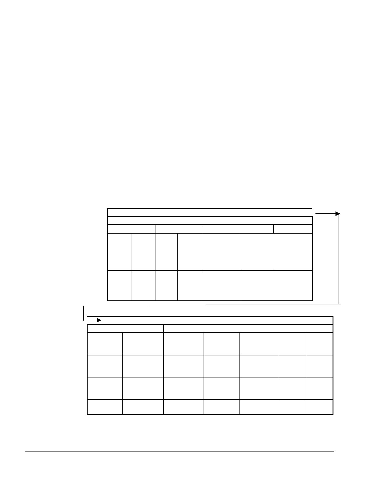
4. Press the DOWN key to scroll down through the setpoi nt menus to the third menu which contai ns
Evap LWT=XX.X°F.
5. Press the ENTER key to move the cursor down from the top line to the second line in order to
make the change.
6. Use the ARROW keys (now in the edit mode as shown above) to change the setting.
7. When the desired value is achieved, press ENTER to enter it and also move the cursor down.
At this point, the following actions can be taken:
1. Change another setpoint in this menu by scrolling to it with the ENTER key.
2. Using the ENTER key, scroll to the first line in the menu. From there the ARROW keys can be
used to scroll to different menus.
Menu Screens
Various menus are shown in the controller display. Each menu screen shows specific information, in
some cases menus are only to
cases they are used to
set setpoint values that can be changed.
The menus are arranged in a matrix of screens across a top horizontal row. Some of these top-level
screens have sub-screens located under them. The content of each screen and its location in the
matrix are shown in Figure 25. A description of each menu begins on page 61.
The arro w keys on the controller are used to navigate through the menus. The keys are also used to
change numerical setpoint values contained in certain menus.
Figure 25, Menu Matrix
view status of the unit, in some cases for checking alarms, and in some
UNIT CIRCUITS REFRIGERANT FANS
VIEW UNIT
STATUS
VIEW UNIT
STATUS
VIEW UNIT
TEMP
(1)
(5)
(1)
VIEW UNIT
TEMP
(2)
VIEW
CIRC #1
STATUS
(1)
VIEW
COMP #1
STATUS
(3)
⇐ Continued ⇐
(Right side of matrix continued from above)m
"ALARM" MENUS "SET" MENUS
ALARM LOG
(LAST)
TYPE, TIME
ALARM LOG
(NEXT TO LAST)
ALARN LOG
(SECOND TO
LAST)
ALARM LOG
LAST 25 SHOWN
ACTIVE ALARM ( 1)
TYPE, TIME
ACTIVE ALARM ( 2)
TYPE, TIME
ADDITIONAL
ACTIVE ALARM ( 3)
CLEAR/VIEW
SET UNIT SPs , (4 )
SET UNIT SPs, (1) SET COM P SPs
SET UNIT SPs, (2) SET COM P SPs
SET UNIT SPs, (3) SET LIMIT ALARMS
(to 13)
"VIEW" MENUS
VIEW
CIRC #2
STATUS
(1)
VIEW
CIRC #2
STATUS
(3)
"MENU"
(1
(2)
(3)
VIEW FAN/TOWER
(1)
VIEW FAN/TOWER
(n)
SET FANS (1)
STAGES
FANTROL
SET FANS (2)
STAGE ON
SET FANS (3)
STAGE O FF
VIEW
REFRIGERANT
CIRCUIT #1
(1)
VIEW EVAP
(2)
(1)
(2)
SET TOWER
VIEW
REFRIGERANT
CIRCUIT #2
(1)
VIEW EVAP
(2)
SET LIMIT ALARMS
SET LIMIT ALARMS
SET
TOWER (1)
SET
TOWER (2)
SET
TOWER (3)
(to n)
Selection can be made within the matrix by using the LEFT/RIGHT keys to move between columns
and the UP/DOWN keys to move between rows.
60 WGZ 030A through 100A IOMM WGZ-1
Page 61

Menu Descriptions
This section contains information on each screen. The menu screens are in order of the matrix in
Figure 25 on p age 6 0 going fr om left to right and down when there ar e sub-menus. Ma ny menus are
self-explanatory. A Setpoint menu allows selection of whether the unit has a water-cooled condenser,
WaterCooled = Y (Yes) or a remote condenser, WaterCooled = N (No). This selection will alter some
menus as appropriate to the type of condenser.
Screen Definitions – ME NU
Top level menu:
< ALARM
< VIEW
< SET
<
ALARM menu:
ALARM < ACTIVE
< LOG
<
<
VIEW menu:
VIEW < COMPRESSOR
< UNIT
< EVAPORATOR
< FANS/TOWER
VIEW UNIT menu:
VIEW < TEMP
UNIT < STATUS
< REFRIGERANT
SET menu:
SET < ALARM LIMITS
< UNIT SPs
< COMPRESSOR SPs
< FANS/TOWER SPs
Screen Definitions – VIEW
View Unit Status
VIEW UNIT STATUS (1)
Auto
Cooling Stage = 0
Evap Pump = RUN
Unit states can be OFF, COOL, GYLCOL, ICE, or ALARM as determined from the Unit Mode
setpoint, the Unit Enable, and the presence of an alarm.
Circuit states can be OFF/OFF, ON/OFF, OFF/ON, and ON/ON.
Evaporator Pump States can be OFF, STRT, or RUN.
IOMM WGZ-1 WGZ 030A through 100A 61
Page 62

When more than one screen are stacked (i.e., relate to each other on the same subject), they are
numbered sequentially with the numbers appearing in the upper-right corner.
VIEW UNIT STATUS (2)
Demand Limit=Stg 4
Network Limit=Stg 4
VIEW UNIT STATUS (3)
Stg Up Delay=XXX sec
Stg Dn Delay=XXX sec
Ice Delay=XXh XXm
VIEW UNIT STATUS (4)
D.O. 111111111
123456789012345678
000000000000000000
This menu gives the status o f digital o utputs ( D.O.), 1=ON, 0=OFF. Numbers are 1 through 18. See
Table 23 on page 49 for number reference.
VIEW UNIT STATUS (5)
D.I. 111111111
123456789012345678
000000000000000000
This menu gives the status o f digital inputs (D.I .), 1=ON, 0= OFF. Numbers are 1 through 18. See
Table 22 on page 49 for number reference.
Water Cooled = Y Water Cooled = N
VIEW UNIT TEMP (1) VIEW UNIT TEMP (1)
Evap LWT = XX.X°°°°F Evap LWT = XX.X°°°°F
Cond EWT = XXX.X°°°°F OAT = XXX.X°°°°F
LWT Target = XX.X°°°°F LWT Target = XX.X°°°°F
The difference between the two screens above is that water-cooled units will give the entering
condenser water temperature and air-cooled units will give the outside air temperature (OAT). The
outside-air temperature sensor is furnished with the unit, inside the control panel, wired to the correct
terminals. It must be installed outdoors in a location that will give the true outdoor temperature that
the condenser coils will see. Splicing of the sensor lead may be required. The unit will not operate
without the sensor installed.
VIEW UNIT TEMP (2)
LWT Pulldn= XX.X °°°°F
Control Band= XX.X°°°°F
VIEW CIRCUIT#1 (1)
OFF
62 WGZ 030A through 100A IOMM WGZ-1
Page 63

VIEW CIRCUIT#1 (2)
Comp 1 = OFF
Hours = XXXXX
Starts = XXXXX
VIEW CIRCUITt#1 (3)
Comp 3 = OFF
Hours = XXXXX
Starts = XXXXX
VIEW CIRCUIT#2 (1)
Off
VIEW CIRCUIT#2 (2)
Comp 2 = OFF
Hours = XXXXX
Starts = XXXXX
VIEW CIRCUIT#2 (3)
Comp 4 = OFF
Hours = XXXXX
Starts = XXXXX
VIEW REFRG Cir 1 (1)
psi °°°°F
Sat Evap XXX.X XX.X
Sat Cond XXX.X XX.X
VIEW REFRG Cir 1 (2)
SuctionTemp=XXX.X°°°°F
Surperheat = XXX.X°°°°F
EvapApproach= XX.X°°°°F
VIEW REFRG Cir 2 (1)
psi °°°°F
Sat Evap XXX.X XX.X
Sat Cond XXX.X XX.X
VIEW REFRG Cir 2 (2)
SuctionTemp=XXX.X°°°°F
Surperheat = XXX.X°°°°F
EvapApproach= XX.X°°°°F
IOMM WGZ-1 WGZ 030A through 100A 63
Page 64

Water Cooled = N Only
VIEW FANS
Circuit#1 ON=1of4
Circuit#2 ON=1of4
This screen shows the number of air-cooled condenser fans "on" for each circuit. This screen will
show the fans "on" whether they are actually connected to and controlled by the MicroTech II
controller or not.
Water Cooled = Y Only
VIEW TOWER (1)
Stages ON=1of2
EntCondTemp = XXX °°°°F
Setpoint = XXX °°°°F
The first Stages ON value is the number of fan stages ON. The second number is the Tower Stages
setpoint (0 if Tower Control = None). This screen shows the number of tower fans "on" for each
circuit. This screen will show the fans "on" whether they are actually connected to and controlled by
the MicroTech II controller or not.
Water Cooled = Y Only
VIEW TOWER (2)
Bypass Valve = XXX%
VFD Speed = XXX%
The Bypass Valve value shall be “None” (in place of XXX%) if the Valve/VFD Control setpoint =
None or VFD Stage. The VFD Speed value shall be “None” if the Valve/VFD Control setpoint =
None, Valve Setpoint, or Valve Stage.
Screen Definitions – ALARM
ALARM ACTIVE (1)
Alarm Description
hh:mm:ss dd/mmm/yyyy
OR
ALARM ACTIVE (X)
No more alarms
Press ENTER to clear
all active alarms
If the unit is off on a shut down alarm or running, b ut in a limit alarm condition, the cause and date
will appear in the upper screen. If there is a simultaneous occurrence of more than one alarm, the
others will appear in additional screens below the first one, accessed by the DOWN ARROW. Either
type alarm will light a red light in back of the LEFT-ARROW KEY. The light will go out when the
fault is cleared. To clear the fault, scroll down to the last screen and press ENTER. If other faults
have appeared, they will all be cleared at the same time.
64 WGZ 030A through 100A IOMM WGZ-1
Page 65

ALARM LOG (1)
Alarm Description
hh:mm:ss dd/mmm/yyyy
Data
The last 25 alarms, either shutdown or limit, are shown in this menu and subsequent menus located
under it. ARROW DOWN from this menu will go to the next-to-last alarm, ARROW DOWN again
will go to the second from last, and so o n through the last 25 occur rences. The scr eens are numbered
(1), (2), (3), etc.
Screen Definitions – SET
Set Unit Setpoints
SET UNIT SPs (1)
Unit Enable = OFF
Unit Mode = COOL
Source = KEYPAD
Unit Enable settings can be OFF and ON as determined from the Unit Enable setpoint.
Unit Enable is an external signal or a keypad setting that keeps the unit off when the setting is OFF
and
allows it to run if there is a call for cooling when the setting is ON. The source for the signal is
selected in the 4
th
line and can be:
1. KEYPAD, in which case the selection is made in line 2 and would be normally selected as ON.
This is the normal setting when no external signals are controlling the unit.
2. SWITCHES, in which an external switch is wired across terminals #25 and #35. (See wiring
diagram page 39 or 40.)
3. NETWORK, used with BAS signal, which is wired to the three communication ports.
Unit Mode settings can be
1. COOL, normal setting used with chilled water air-condition applications.
2. COOL w/GLYCOL, used with low temperature, glycol applications. It allows a lower LWT
setpoint to be used.
3. ICE w/GLYCOL, used with ice storage systems, allows changing from chilled glycol operation to
lower temperature ICE operation. In ICE, the unit runs at full load until the ICE setpoint is
reached, at which time the unit shuts off. A three-position switch wired to terminals #28 and #38
initiates the change from glycol cooling to making ice. (See wiring diagrams on page 39 or 40.)
Unit Mode settings can be COOL COOLw/Glycol, or ICEw/Glycol, as determined from the Unit
Mode setpoint.
Source settings can be KEYPAD, SWITCHES, or NETWORK as determined from the Mode Source
setpoint.
SET UNIT SPs (2)
Available Modes
=COOL w/Glycol
Set w/Unit Switch Off
IOMM WGZ-1 WGZ 030A through 100A 65
Page 66

SET UNIT SPs (3)
Evap LWT = XX.X°°°°F
Ice LWT = XX.X°°°°F
EvapDeltaT= XX.X°°°°F
SET UNIT SPs (4)
Start Delta= XX.X°°°°F
Stop Delta= XX.X°°°°F
See page 45 for an explanation of compressor staging.
SET UNIT SPs (5)
Max Pulldn=x.x°°°°F/min
Evap Recirc=XXX sec
LowAmbLock=XX.X°°°°F
SET UNIT SPs (6)
Demand Limit=Off
Water cooled=Off
Water Cooled = On is the setting for units with on-board water-cooled condensers. WaterCooled =
OFF is used for units with remote condensers, usually air-cooled.
SET UNIT SPs (7)
Ice Time Delay=Xxsec
Clear Ice Delay=No
SET UNIT SPs (8)
CLOCK
dd/mmm/yyyy
hh:mm:ss
SET UNIT SPs (9)
Units = °°°°F/psi
Lang = ENGLISH
Lang (Language) setting is ENGLISH.
66 WGZ 030A through 100A IOMM WGZ-1
Page 67

SET UNIT SPs (10)
Protocol = NONE
Ident Number=001
Baud Rate=9600
BAS interface settings, available mid-2003.
SET UNIT SPs (11)
Evap Press Sensor
Cir 1 Cir 2 Offset
00.0 00.0 (psi)
The pressure offsets on menus 8 and 9 and the temperature offsets on menus 10, 11 and 12 correct the
controller's display of the parameters. The sensors used in these units have a high degree of
repeatability but may need correction (offset). An accurate pressure gauge or thermometer is used to
determine the correct temperature or pressure. A positive or negative offset value is then entered to
make the controller reading agree with the measured value.
SET UNIT SPs (12)
Cond Press Sensor
Cir 1 Cir 2 Offset
00.0 00.0 (psi)
SET UNIT SPs (13)
Leaving Evaporator
Water Temp Sensor
Offset= 00.0oF
SET UNIT SPs (14)
OAT/Cond Lvg Water
Temperature Sensor
Offset= 00.0oF
SET UNIT SPs (15)
Suction Temp Sensor
Cir 1 Cir 2 Offset
00.0 00.0 (oF)
SET UNIT SPs (16)
ENTER PASSWORD: XXXX
Active Password
Level: None
Two four-digit passwords provide OPERATOR and MANAGER levels of access to changeable
parameters. The passwords are preprogrammed into the controller. Either password must be entered
using the ENTER PASSWORD (12) screen before a protected setting can be changed. The operator
password is 0100. The manager level is 2001.
IOMM WGZ-1 WGZ 030A through 100A 67
Page 68

This screen can be accessed either thr ough the SE T OTHE R menu or by simply pressing the ENTER
key while on one of the SET screens. The controller will automatically go from the screen with the
setting change to this screen. After the correct password has been entered, the controller will
automatically return to the original set screen.
Once a password has been entered, it remains valid for 15 minutes after the last key-press.
Set Compressor Setpoints
SET COMP SPs k,(1)
Clear Cycle Tmr=No
Stop-Start =XXmin
Start-Start =XXmin
This menu sets the anti-recycle timers. Stop-Start is the time required before starting a compressor
after it has
has
Clear Cycle Tmr overrides the anti-recycle timers and should only be used for service testing and not
for normal unit operation.
stopped. Start-Start is the time required before starting a compressor after the last time it
started. It is recommended that the default values of 5 minutes and 15 minutes not be changed.
SET COMP SPs (2)
InterStgUp =XXXsec
InterStgDown= XXsec
InterStageUp is the time delay since the last stage change before a compressor can stage on, default is
120 sec.
InterStageDn is the time delay since the last stage change before a compressor can stage off normally
(not by an alarm). Default is 30 sec. It is recommended that these settings not be changed.
SET ALARM LMTS (1)
LowEvPrHold=XXXpsi
LowEvPrUnld=XXXpsi
LowEvPrStop=XXXpsi
The LowEvPrHold and LowEvPrUnld have the same default value of 59 psi. If two compressors are
running, the LowEvPrUnld is in effect and the la g compressor will be shut off to unload the unit. If
one compresso r is running, the Lo wEvPrHold is in effect and the lag compresso r is prevented from
starting, thereby holding the unit capacity.
The last action to take place is the shutoff of all compressors running when the LowEvPrStop setting
is reached (default is 58 psi). Reducing these time intervals will increase detrimental compressor
cycling. It is recommended that these settings not be changed.
SET ALARM LMTS (2)
LowEvpPrDelay=XXs
Evap Freeze= XX.X°°°°F
EvapFlowProof=XXXsec
Evap Freeze (the unit freeze protection shutdown) is actually a stop alarm and shuts off the unit when
the LWT reaches 36°F. It is cleared by going to the CLEAR ALARM menu in the ACTIVE ALARM
hierarchy.
LowEvPrDelay is a time delay on the low pressure trip that reduces nuisance low-pressure trips. The
default setting is 30 seconds.
EvapFlowProof is the flow switch interlock. Closing the flow switch and therefore proving the
existence of chilled water flow resets this trip. It is recommended that these settings not be changed.
68 WGZ 030A through 100A IOMM WGZ-1
Page 69

SET ALARM LMTS (3)
HiCondPr =XXX.Xpsi
HiPrStgDn=XXX.Xpsi
CondFreeze=xx.x°°°°F
HighCondPr ( the unit high-discha rge-pressure shutd own) is a stop a larm that shuts off the unit when
the discharge pressure reaches the setting. The default setting is 380 psi.
The HiCondStgDn is a limit alarm that unloads the unit at 370 psi in an attempt to prevent total
shutdown from the HighCondPr at 380 psi. The stage down is set at 370 psi. It is recommended that
these settings not be changed.
CondFreeze is an alarm that reduces the chance of freezing the water in the condenser (when
compressors are not runni ng). An alarm is registere d and the condenser pump is energiz ed at the
same time. The alarm setpoint is 34°F saturated condenser temperature and it resets at +2°F above
the setpoint.
SET ALARM LMTS (4)
GroundFault = N
PhaseVoltage = N
LowAmbLock= XX °°°°F
GroundFault and PhaseVoltage entries are Y (Yes) or N (No) depending on whether the options are on
the unit.
LowAmbientLock applies to units with air-cooled condensers and prevents unit operation below the
setting. The available range is -2°F to 60°F with a default of 35°F.
Set Air-Cooled Condenser Fans
SET FANS SPs (1)
Fan Stages=X
Speedtrol=Yes/No
SET FANS SPs (2)
Stage ON psi
#1/2 #3/4
XXXX XXXX
SET FANS SPs (3)
Stage ON psi
#5/6 #7/8
XXXX XXXX
SET FANS SPs (4)
Stage Off psi
#1/2 #3/4
XXXX XXXX
IOMM WGZ-1 WGZ 030A through 100A 69
Page 70

SET FANS SPs (5)
Stage Off psi
#5/6 #7/8
XXXX XXXX
The SET FANS SP screens 2 through 5 esta blish the di scharge pre ssures that will stage the condenser
fans on and off. These screens apply only to units set up for use with air-cooled condensers
(WaterCooled=No). On such units, the settings do not have to be entered if the unit controller is not
used to stage condenser fans for head pressure control. If the MicroTech II unit controller is not used
to control the fans, some other method must be used.
Set Cooling Tower Control
The MicroTech II controller is capable of controlling cooling tower water temperature on chillers
using water-cooled condensers. Output wiring connection points are shown on the field wiring
diagrams.
[Water Cooled = Y] - Condenser Pump on with first Compressor on. Tower fan control is active when
the Tower Control setpoint is set to Temperature and the condenser pump is in the RUN state.
Staging is based on Entering Condenser Water Temperature (ECWT). Operation depends on the
following parameters.
• Condenser pump state
• ECWT OR Lift pressure
• Stage up and stage down timer values
• Tower setpoints (Tower Control, Tower Stages, Stage Up Time, Stage Down Time, Stage
Differential, Stage #1 ON, Stage #2 ON, Stage Down @, Stage Up @)
When the condenser pump starts, the stage up timer shall start. The first stage shall turn ON when the
following conditions are met:
• The stage up timer completes
• The ECWT is > Stage #1 ON setpoint
• Bypass valve position is > the Stage Up @ setpoint (only if Valve/VFD Control setpoint = Valve
Stage)
Additional stages can turn on (up to the number specified by the Tower Stages setpoint) when above
conditions are met for the next stage plus the following condition:
• VFD Speed is > the Stage Up @ setpoint (only if Valve/VFD Control setpoint = VFD Stage OR
Valve SP/VFD Stage)
Down staging shall occur when the following conditions are met:
• The stage down timer completes
• The ECWT is < Stage #X ON (Temp) setpoint – Stage Differential (Temp) setpoint point
• Bypass valve position is < the Stage Down @ setpoint (only if Valve/VFD Control setpoint =
Valve Stage)
• VFD Speed is < the Stage Down @ setpoint (only if Valve/VFD Control setpoint = VFD Stage
OR Valve SP/VFD Stage)
Each stage up or stage down event shall restart both the stage up and stage down timers. Only one fan
output shall be switched at a time (except that all outputs switch OFF when the condenser pump state
equals OFF).
70 WGZ 030A through 100A IOMM WGZ-1
Page 71

SET TOWER SPs (1)
Tower Control= None
Tower Stages = X
StageUP/DN=XXX/XXX%
When Tower Control is None the control of condenser water temperature is not by the MicroTech II
controller and assumed to be furnished elsewhere.
Tower Stages is the number of tower fans to be staged by the controller, choices are 0, 1, or 2. "0"
indicates control will be by a bypass valve or variable speed pump controlled by the MicroTech II
controller.
StageUP/DN imposes a time delay between fan stages when turning on or turning off.
SET TOWER SPs (2)
Stage ON (Temp)°°°°F
#1 #2
XXX XXX
Stage ON Temp is the entering condenser water temperature (ECWT) that will turn on tower fan #1
and #2. Default settings are 70°F and 75°F. Cold condenser water will improve unit efficiency but
too cold can cause erratic operation. Settings below 60°F are not recommended.
SET TOWER SPs (3)
StageDiff = XX.X°°°°F
Stage Up = XX min
StageDown = XX min
StageDiff is the number of degrees below the Stage ON that will turn off the tower fans. For
example, if Stage ON #1 is 70°F and StageDiff is 5°F, tower fan #1 will stage off when the ECWT
drops to 65°F and stage the fan on when the ECWT rises to 70°F. The same is true for fan #2.
Stage Up timer is the number of minutes that must elapse between the condenser pump starting (it
starts with the unit) and fan #1 starting or the time between fan #1 starting and fan #2 starting.
StageDown is the elapsed time between staging down the fan motors.
SET TOWER SPs (4)
Valve/VFD Control=
ValveSP/VFDStage
Valve Type = NC
Valve/VFD Control settings are None, Valve Setpoint, Valve Stage, VFD Stage, or
Va lveSP/VFDStage. Default is None which results in no control of the tower from the MicroTech II
controller.
• Valve Setpoint
established by the Set Tower SPs in screen (5) below.
, the valve will control (bypass tower) to hold the minimum temperature as
This mode is operational when the Valve/VFD Control setpoint is set to Valve Setpoint OR Valve
SP/VFD Stage. In this mode the valve output is varied with a proportional-derivative (PD)
algorithm (with deadband) in order to maintain the controlled parameter (CP) at the desired
value. The output is always limited between the Valve Control Range (Min) setpoint and the
Valve Control Range (Max) setpoint. A valve increment shall be computed once every 5 seconds
according to the following equation. (Error Gain and Slope Gain are set in menu screen #8.)
IOMM WGZ-1 WGZ 030A through 100A 71
Page 72

Increment = [(Error) * (Error Gain setpoint)] + [(Slope) * (Slope Gain setpoint)]
Where: Error = ECWT – Valve Setpoint
Slope = (Present CP) – (Previous CP)
When the Error is > the Valve Deadband setpoint, the valve position analog output (% of full
scale) is updated according to the following equation.
New %Position = Old %Position + Increment/10
• Valve Stage
Setpoint method explained above be used rather than this mode.
This mode is only operational when the Valve/VFD Control setpoint is set to Valve Stage. In this
mode the valve output is controlled as for Valve Setpoint mode (above), except that the active
setpoint for the controlled parameter is selected according to the following table.
• VFD Stage
Setpoint, OR Valve Stage, this output is set to 0. Otherwise, it will be controlled in a manner
identical to Valve Stage Mode (above) except that (1) it shall be kept at zero until the first fan
stage is ON, and (2) the following setpoints do not apply.
Valve Control Range (Min)
Valve Control Range (Max)
Valve Type
Valve Type settings are NC (normally closed to tower) or NO (normally open).
These settings establish the operation of a tower bypass valve (must be a 3-way valve).
, controls from the fan stage setpoint in use. It is recommended that the Valve
# Of Fans ON Active Setpoint
0 Valve Setpoint
1 Stage #1 ON
2 Stage #2 ON
3 Stage #3 ON
4 Stage #4 ON
, ValveSP/VFDStage, When the Valve/VFD Control setpoint is set to None, Valve
Initial Va lve Position
When the condenser pump is not in the RUN state, the valve output shall be set as a function of
entering condenser water temperature (ECWT) per the following graph.
Figure 26, Initial Valve Position
Initial Valve Position
Max Position @
(values are examples only)
Setpoint
(90°F)
Min Position @
Setpoint
(60°F)
Min Start Position
Setpoint
72 WGZ 030A through 100A IOMM WGZ-1
(10%)
Max Start Position
Setpoint
(90%)
Page 73

Operation After Start
When the condenser pump is in the RUN state, the valve output shall be controlled in one of two
modes as specified by the Valve/VFD Control setpoint. The controlled parameter shall be the
condenser entering water temperature. When the desired output signal varies from 0 to 100%, the
output voltage shall vary as shown below.
0 to 10 VDC (Valve Type = NC)
10 to 0 VDC (Valve Type = NO)
SET TOWER SPs (5)
Valve SP = XXX °°°°F
Valve DB = XX.X °°°°F
Valve SP is the minimum tower water temperature acceptable, default is 65°F.
Va lve DB is the dead-band in degrees, default is 2.0°F.
SET TOWER SPs (6)
ValveStartPosition
Min = XXX% @XXX°°°°F
Max = XXX% @XXX°°°°F
The ValveStartposition is the position of the valve when the unit starts. Default for minimum start
position is 0%, and 100% for maximum position.
SET TOWER SPs (7)
Valve Control Range
Min = XXX%
Max = XXX%
Defaults are 10% minimum and 90% maximum.
SET TOWER SPs (8)
PD Control Loop
Error Gain = XX
Slope Gain = XX
Defaults are 25 for both error and slope.
Editing Review
Editing shall be accomplished by pressing the ENTER key until the desired field is selected. This
field shall be indicated by a blinking cursor under it. The arrow keys shall then operate as defined
below.
CANCEL (Right) Reset the current field to the value it had when editing began.
DEFAULT (Left) Set value to original factory setting.
INCREMENT (Up) Increase the value or select the next item in a list.
DECREMENT (Down) Decrease the value or select the previous item in a list.
During edit mode, the display shall show a two-character wide menu pane on the right as shown
below.
IOMM WGZ-1 WGZ 030A through 100A 73
Page 74

SET UNIT SPs (X) <D
(data) <C
(data) <+
(data) <-
Additional fields can be edited by pressing the ENTER key until the desired field is selected. When
the last field is selected, pressing the ENTER key switches the display out of “edit” mode and returns
the arrow keys to “scroll” mode.
Alarms
When an alarm occurs, the alarm type, limit value (if any), date, and time are stored in the active
alarm buffer corresponding to that alarm (viewed on the Alarm Active screens) and also in the alarm
history buffer (viewed on the Alarm Log screens). The active alarm buffers hold a record of the last
occurrence of each alarm and whether or not it has been cleared. The alarm can be cleared by
pressing the Edit key. A separate buffer is available for each alarm (High Cond Pressure, Evaporator
Freeze Protect, etc.). The alarm history buffer holds a chronological account of the last 25 alarms of
any type.
Security
Two four-digit passwords provide OPERATOR and MANAGER levels of access to changeable
parameters. Either password can be entered using the ENTER PASSWORD screen which can be
accessed either through the SET OTHER menu or b y simply pressing the ENTER key while on one of
the SET screens. The password can then be entered by pressing the ENTER key, scrolling to the
correct value with the UP and DOWN arrow keys, and pressing ENTER again. Once the correct
password has been entered, the previously selected screen will reappear. Once a password has been
entered, it will remain valid for 15 minutes after the last key-press.
BAS Interface
The MicroTech II controller is equipped with the Protocol Selectability feature, an exclusive
McQuay feature that provides easy unit interface with a building automation system. If the unit will
be tied into a BAS, the controller should have been purchased with the correct factory-installed
interface module. The modules can also be added in the field during or after installation.
If an interface module was ordered, one of the following BAS interface installation manuals was
shipped with the unit. Contact your local McQuay sales office for a replacement, if necessary.
• IM 735, L
• IM 736, BACnet Communication Module Installation
ONWORKS Communication Module Installation
74 WGZ 030A through 100A IOMM WGZ-1
Page 75

Optional Controls
Phase/Voltage Monitor (Optional)
The phase/voltage monitor is a device that provides protection against three-phase electrical motor
loss due to power failure conditions, phase loss, and phase reversal. Whenever any of these conditions
occur, an input relay is deactivated, disconnecting power to the thermostatic control circuit. The
compressor do a rapid shutdown pump down.
The input relay remains deactivated until power line conditions return to an acceptable level. Trip and
reset delays have been provided to prevent nuisance tripping due to rapid power fluctuations.
When three-phase power has been applied, the input relay should close and the “run light” should
come on. If the relay does not close, perform the following tests.
1. Check the voltages between L1-L2, L1-L3, and L2-L3. These voltages should be approximately
equal and within +10% of the rated three-phase line-to-line voltage.
2. If these voltages are extremely low or widely unbalanced, check the power system to determine
the cause of the problem.
3. If the voltages are good, turn off the power and inter-change any two of the supply power leads at
the disconnect switch.
This may be necessary, as the phase/voltage monitor is sensitive to phase reversal. Turn on the power.
The relay should now close after the appropriate delay.
Factory settings are as follows:
Voltage Setting, set at nameplate voltage.
Trip Delay Time, 2 seconds
Restart Delay Time, 60 seconds
Hot Gas Bypass (Optional)
This option allows passage of discharge gas to the evaporator, permitting operation at lower loads
than available with compressor unloadi ng. It also keeps the velocity of refrigerant gas high enough
for proper oil return at light load conditions.
The pressure regulating valve is a Sporlan SHGBE-8 and factory set to begin opening at 69 psig and
can be changed by changing the pressure setting. The adjustment range is 0 to 100 psig. To raise the
pressure setting, remove the cap on the bulb and turn the adjustment screw clockwise. To lower the
setting, turn the screw counterclockwise. Do not force the adjustment beyond the range it is designed
for, as this will damage the adjustment assembly. The regulating valve opening point can be
determined by slowly reducing the system load while observing the suction pressure. When the
bypass valve starts to open, the refrigerant line on the evaporator side of the valve will begin to feel
warm to the touch.
WARNING
The hot gas line can become hot enough to cause personal injury in a very short
time; care should be taken during valve checkout.
IOMM WGZ-1 WGZ 030A through 100A 75
Page 76

System Maintenance
General
To provide smooth operation at peak capacity and to avoid damage to package components, a
program of periodic inspections should be set up and followed. The following items are intended as a
guide to be used during inspection and must be combined with sound refrigeration and electrical
practices to provide trouble-free performance.
The liquid line sight glass/moisture indicator on all circuits must be checked to be sure that the glass
is full and clear and that the moisture indicator indicates a dry condition. If the indicator shows that a
wet condition exists or if bubbles show in the glass, even with a full refrigerant charge, the filter-drier
element must be changed.
Water supplies in some areas can tend to foul the water-cooled condenser to the point where cleaning
is necessary. The fouled condenser will be indicated by an abnormally high condenser approach
temperature (saturated discharge temperature minus leaving condenser water temperature) and can
result in nuisance trip-outs. To clean the condenser, mechanical cleaning or a chemical descaling
solution should be used according to the manufacturer’s directions.
Systems with remote air-cooled condensers require periodic cleaning of the finned surface of the
condenser coil.
Cleaning can be accomplished by using a cold water spray, brushing, vacuuming, or high-pressure air.
No tools should be used that could damage the coil tubes or fins.
The compressor oil level must be checked periodically to be sure that the level is at the center of the
oil sightglass located in the compressor's equalizing line or on the compressor itself. Low oil level
can cause inadequate lubrication and if oil must be added, use oils referred to in the following
“Compressor Lubrication” section.
A pressure tap has been provided on the liquid line downstream of the filter-drier and solenoid valve
but before the expansion valve. An accurate subcooled liquid pressure and temperature can be taken
here. The pr essure re ad her e could also p rovid e an indic ation o f excessive pr essure dr op thro ugh the
filter-drier and soleno id valve due to a clogging filter-drier. Note: A normal pressure drop through the
solenoid valve is approximately 3 psig (20.7 kPa) at full load conditions.
CAUTION
Warranty may be affected if wiring is not in accordance with specifications. A blown
fuse or tripped protector indicates a short ground or overload. Before replacing fuse
or restarting compressor, the trouble must be found and corrected. It is important to
have a qualified control panel electrician service this panel. Unqualified tampering
with the controls can cause serious damage to equipment and void the warranty.
DANGER
The panel is always energized to ground even when the sys tem switch is off.
To de-energize the complete panel including crankcase heaters, pull the main unit
disconnect. Failure to do so can result in severe personal injury or death.
If motor or compressor damage is suspected, do not restart until qualified service personnel have
checked the unit.
76 WGZ 030A through 100A IOMM WGZ-1
Page 77

Electrical Terminals
WARNING
To avoid injury from electric shock hazard, turn off all power and perform lockout and
tag-out of source before c ontinuing with the following service. Note that the unit
might be powered from multiple sources.
All power electrical terminals should be re-tightened every six months, as they tend to loosen due to
normal heating and cooling of the wire.
Compressor Lubrication
The oil level should be watched carefully upon initial start-up and regularly thereafter.
All tandem compressors on WGZ units come equipped with one or two oil equalization lines
connecting the crankcase of each set of compressors in each refrigerant circuit. This allows the oil to
move from one compressor crankcase to the other during normal operation, and balance between the
two when the compressors are off. The oil sight glass is located in the equalization line on one circuit
of the WGZ 070 and both circuits of WGZ 080 through WGZ 100. All other models have the oil
sight glass in the compressor body. In either case, the oil level should be 1/4 to 1/3 of the glass.
At the present time, standard refrigerant mineral oils such as Suniso No. 3GS, Calumet R015, and
Texaco WF32 oils are approved by Copeland for use in these compressors.
Oil can be added to the Copeland compressor through the oil fill hole in the crankcase. Special
equipment is required to add oil and the work should be done by qualified refrigeration technicians
with the proper training and equipment.
Sight glass and Moisture Indicator
The refrigerant sight glasses should be observed periodically. A monthly observation should be
adequate. A clear glass of liquid indicates that there is adequate refrigerant charge in the system to
provide p roper feed through the expansion valve. The sight glass should be clear when:
• Ambient temperature is above 75°F (23°C)
• Both compre ssors on a circuit are running
• All fans on a circuit are running
Bubbling refrigerant in the sight glass may occur at other conditions and
is short of refrigerant charge. Refrigerant gas flashing in the sight glass could also indicate an
excessive pressure drop in the line, possibly due to a clogged filter-drier or a restriction elsewhere in
the system. An element inside the sight glass indicates what moisture condition corresponds to a
given element color. If the sight glass does not indicate a dry condition after about 12 hours of
operation, the unit should be pumped down and the filter-driers changed.
If the system is suspected of being short of refrigerant, a qualified service technician with EPA
certification should be contacted to thoroughly check out the unit and add refrigerant if necessary.
may indicate that the system
Crankcase Heaters
The compressors are equipped with crankcase heaters. The function of the heater is to keep the
temperature in the crankca se high enough to prevent re frigerant fr om migrating to the crankcase and
condensing in the oil during off-cycle. When a system is to be started up initially, the power to the
heaters should be turned on for at least 12 hours before the compressors are started. The crankcase
should be up to about 80°F (26.7°C) before the system is started up, to minimize lubrication problems
or liquid sluggi ng of compressor on start-up.
If the crankcase is cool (below 80°F) (26.7°C) and the oil level in the sight glass is full to top, allow
more time for oil to warm before starting the compressor.
The crankcase heaters are on whenever power is supplied to the unit and the compressor is not
running.
IOMM WGZ-1 WGZ 030A through 100A 77
Page 78

Maintenance Schedule
I. Compressor
A. Performance Evaluation (Log & Analysis) * O
B. Motor
• Meg. Windings
• Ampere Balance (within 10%)
• Terminal Check (tight connections, porcelain cl ean)
• Motor Cooling (check tem perature)
C. Lubrication System
• Oil Level
• Oil Appearance (clear color, quantity)
• Oil change if indicated by oil analysis
II. Controls
A. Operating Controls
• Check Settings and Operati on
B. Protective Controls
• Test Operation of:
Alarm Relay X
Pump Interlocks X
High and Low Pressure Cutouts X
III. Condenser
B. Test Water Quality X
C. Clean Condenser Tubes (or as required) X
D. Eddycurrent Test - Tube Wall Thickness X
E. Seasonal Protecti on X
IV. Evaporator
B. Test Water Quality X
C. Clean Evaporator Tubes (or as required) X
D. Eddycurrent Test - Tube Wall thickness (or as required) X
E. Seasonal Protecti on X
V. Expansion Valves
A. Performance Evaluation (Superheat Control) X
VI. Compressor - Chiller Unit
A. Performance Evaluat i on O
B. Leak Test:
• Compressor Fittings and Terminal
• Piping Fittings
• Vessel Relief Valves
C. Vibration Isolation Test X
D. General Appearance:
• Paint
• Insulation
VII. Starter(s)
A. Examine Contactors (hardware and operation) X
B. Verify Overload Setting and Tri p X
C. Test Electrical Connections X
VIII. Optional Controls
A. Hot Gas Bypass (verif y operation) X
X
X
X
X
O X
O
X
X
X
X
X
X
X
Key: O = Performed by in-house personnel X = Performed by service personnel
78 WGZ 030A through 100A IOMM WGZ-1
Page 79

System Service
Service on this equipment is to be performed only by qualified refrigeration
personnel. Causes for repeated tripping of equipment protection controls must be
investigated and corrected. Disconnect all power before doing any service inside the
NOTE: Anyone servicing this equipment m ust com ply with the requirements set forth by the
EPA concerning refrigerant reclamation and venting.
Filter-Driers
To change the filter-drier, pump the unit down (with the compressor running) by closing the manual
liquid line shutoff valve(s). The unit will start pumping down until it reaches the low-pressure cutoff
setting of 58 psi.
Close the discharge valve. Remove the refrigerant in the liquid line with a recovery unit to EPA
required pressure. Remove and replace the filter-drier(s). Evacuate the lines through the liquid line
manual shutoff valve(s) to remove noncondensables that may have entered during filter replacement.
A leak check is recommend before returning the unit to operation.
DANGER
unit or serious personal injury or death can occur.
Unit Arrangement Unit Size Type Filter-Drier
Water-Cooled 030 - 060 Sealed/Brazed
Water-Cooled 070 - 100 2-core Replaceable
Remote Condenser All 2-core Replaceable
Liquid Line Solenoid Valve
The liquid line solenoid valve(s), which are responsible for automatic pumpdown during normal unit
operation, do not normally require any maintenance. However, in the event of failure they can require
replacement of the solenoid coil or of the entire valve assembly.
The solenoid coil can be removed from the valve body without opening the refrigerant piping by
moving pumpdown switch(es) PS1 and PS2 to the “manual” position.
The coil can then be removed from the valve body by simply removing a nut or snap-ring located at
the top of the coil. The coil can then be slipped off its mounting stud for replacement. Be sure to
replace the coil on its mounting stud before returning pumpdown switch(es) PS1 and PS2 to the “auto
pumpdown” position.
To replace the entire solenoid valve, follow the steps for changing a filter-drier.
IOMM WGZ-1 WGZ 030A through 100A 79
Page 80

Thermostatic Expansion Valve
The expansion valve is responsible for allowing the proper amount of refrigerant to enter the
evaporator regardless of cooling load. It does this by maintaining a constant superheat. (Superheat is
the difference between refrigerant temperature as it leaves the evaporator and the saturation
temperature corresponding to the evaporator pressure). All WGZ chillers are factory set for between
8°F and 12°F (4.4°C to 6.7°C) superheat at full load. To increase the superheat setting of the valve,
remove the cap at the bottom of the valve to expose the adjustment screw. Turn the screw clockwise
(when viewed from the adjustment screw end) to increase the superheat and counterclockwise to
reduce superheat. Allow time for system rebalance after each superheat adjustment.
The expansion valve, like the solenoid valve, should not normally require replacement, but if it does,
the unit must be pumped down by following the steps involved when changing a filter-drier.
If the problem can be traced to the power element only, it can be unscrewed from the valve body
without removing the valve, but only after pumping the unit down.
Figure 27, Thermostatic Expansion Valve
CAUTION
Adjustment of expansion valve should only be performed by a qualified service
technician. Failure to do so can result in improper unit operation.
Note: Superheat will vary with compressor unloading, but should be approximately as follows:
between 8°F and 12°F (4.4°C and 6.7°C) at full load; between 6°F and 10°F at part load.
Evaporator
The evaporator is a sealed, brazed-stainless steel plate unit. Normally no service work is required on
the evaporator.
Water-cooled Condenser
The condenser is of the shell-and-tube type with water flowing through the tubes and refrigerant in the
shell. External finned copper tubes are rolled into steel tube sheets and to the center dividing tube
sheet. Integral subcoolers are incorporated on all units. All condensers are equipped with 450 psig
(3104 kPa) relief valves. Normal tube cleaning procedures can be followed.
80 WGZ 030A through 100A IOMM WGZ-1
Page 81

Troubleshooting Chart
PROBLEM POSSIBLE CAUSES POSSIBLE CORRECTIVE STEPS
Compressor Will
Not Run
Compressor
Noisy or Vibrating
High Discharge
Pressure
Low Discharge
Pressure
High Suction
Pressure
Low Suction
Pressure
Little or No Oil
Pressure
1. Main switch, circuit breakers open.
2. Fuse blown.
3. Thermal overloads tripped or fuses
blown.
4. Defective contact or or coil.
5. System shut down by equipment
protection devices.
6. No cooling required.
7. Liquid line solenoid will not open.
8. Motor electrical trouble.
9. Loose wiring.
1. Flooding of refrigerant into crank case.
2. Improper piping support on s uction or
liquid line.
3. Worn compressor.
1. Condenser water insufficient or
temperature too high.
2. Fouled condenser tubes (water-cooled
condenser). Clogged spray nozzles
(evaporative condenser). Dirty tube and
fin surface (air cooled c ondenser).
3. Noncondensables in system.
4. System overcharge with refri gerant.
5. Discharge shutoff val ve part i al l y closed.
6. Condenser undersized (air-cooled).
7. High ambient conditi ons.
1. Faultly condenser tem p. regulation.
2. Insufficient ref ri gerant in system.
3. Low suction pressure.
4. Condenser too large.
5. Low ambient conditions.
1. Excessive load.
2. Expansion valve overfeeding.
1. Lack of refrigerant.
2. Evaporator dirty.
3. Clogged liquid line filter-dri er.
4. Clogged suction line or compressor
suction gas strainers .
5. Expansion valve malfuncti oni ng.
6. Condensing temperature too l ow.
7. Compressor will not unload.
8. Insufficient water flow.
1. Clogged suction oil strainer.
2. Excessive liquid in crankcase.
3. Low oil level.
4. Flooding of refrigerant into crank case.
1. Close switch
2. Check el ectrical circuits and motor
winding for shorts or grounds.
Investigate for possi bl e overloading.
Replace fuse or reset breakers after
fault is corrected.
3. Overloads are auto reset. Check unit
closely when unit comes back on line.
4. Repair or replace.
5. Determ i ne type and cause of shutdown
and correct it before resetting protection
switch.
6. None. Wait until unit cal l s for cooling.
7. Repair or replace coil.
8. Check motor for opens, short ci rcuit, or
burnout.
9. Check all wire junc tions. Tighten all
terminal screws.
1. Check superheat sett i ng of expansion
valve.
2. Relocate, add or remove hangers .
3. Replace.
1. Readjust temperature control or water
regulating valve. Investigat e ways t o
increase water supply.
2. Clean.
3. EPA purge the noncondensables .
4. Remove excess refrigerant.
5. Open valve.
6. Check condenser rating tabl es against
the operation.
7. Check condenser rating tabl es against
the operation.
1. Check condenser control operat i on.
2. Check for leaks. Repai r and add charge.
3. See corrective steps for low suction
pressure below.
4. Check condenser rating tabl e agai nst the
operation.
5. Check condenser rating tabl es against
the operation.
1. Reduce load or add additional
equipment.
2. Check remote bulb. Regul ate superheat.
1. Check for leaks. Repai r and add charge.
2. Clean chemically.
3. Replace cartridge(s).
4. Clean strainers.
5. Check and reset for proper superheat .
Replace if necessary.
6. Check means for regulating condensing
temperature.
7. See corrective steps for failure of
compressor to unload.
8. Adjust flow.
1. Clean.
2. Check crankcase heater. Reset
expansion valve for higher superheat.
Check liquid line solenoid valve
operation.
3. Add oil.
4. Adjust thermal expansion val ve.
IOMM WGZ-1 WGZ 030A through 100A 81
Page 82

PROBLEM POSSIBLE CAUSES POSSIBLE CORRECTIVE STEPS
Compressor
Loses Oil
Motor Overload
Relays or Circuit
Breakers Open
Compressor
Thermal Switch
Open
Freeze Protection
Opens
1. Lack of refrigerant.
2. Velocity in risers too low (A-C only).
3. Oil trapped in line.
1. Low voltage during high load conditions.
2. Defective or grounded wiring in motor or
power circuits.
3. Loose power wiring.
4. High condensing temperat ure.
5. Power line fault causing unbalanc ed
voltage.
6. High ambient tem perature around the
overload relay
1. Operating beyond design conditions .
2. Discharge valve partially shut.
1. Thermostat set too low.
2. Low water flow.
3. Low suction pressure.
1. Check for leaks and repair. Add
refrigerant.
2. Check riser sizes.
3. Check pitch of lines and refrigerant
velocities.
1. Check supply voltage for exces sive line
drop.
2. Replace compressor-motor.
3. Check all connections and tighten.
4. See corrective steps for high discharge
pressure.
5. Check Supply voltage. Not i fy power
company. Do not start until fault is
corrected.
6. Provide ventilation to reduc e heat .
1. Add facilities so that c ondit i ons are within
allowable limits.
2. Open valve.
1. Reset to 42°F (6°C) or above.
2. Adjust flow.
3. See “Low Suction Pressure.”
Warranty Statement
Limited Warranty
Consult your local McQuay Representative for warranty details. Refer to Form 933-43285Y. To find
your local McQuay Representative, go to www.mcquay.com.
82 WGZ 030A through 100A IOMM WGZ-1
Page 83

IOMM WGZ-1 WGZ 030A through 100A 83
Page 84

Post Office 2510, Staunton, Virginia 24402 USA • (800) 432-1342 • www.mcquay.com IOMM WGZ-1 (10/04)
 Loading...