

Page 1
Operating Manual
Water-Cooled Scroll Compressor Chillers
WGZ 030AW To WGZ 120AW, Packaged Water-Cooled Chiller
WGZ 030AA To WGZ 120AA, Chiller with Remote Condenser
30 to 120 Tons, 105 to 420 kW
Software Version WGZD20102C
60 Hz, R-22, R-407C
OM WGZ-2
Group: Chiller
Part Number: 331374501
Effective: March 2005
Supercedes: OM WGZ-1
Page 2
Table of Contents
Introduction........................................3
General Description...............................3
Nomenclature........................................3
Water Pressure Drop..............................3
Operating Limits....................................6
Components...........................................6
Unit Configuration ............................7
Field Wiring Diagrams..........................8
Control Panel Layout ..........................10
Motor Protection Module....................10
Start-Up and Shutdown...................11
Pre Start-up.......................................... 11
Start-up................................................11
Weekend or Temporary Shutdown ......12
Start-up after Temporary Shutdown....12
Extended Shutdown.............................12
Start-up after Extended Shutdown ......13
Low Ambient Start ..............................13
Fan High Ambient Rapid Start............14
Sequence of Operation ....................14
Start-up/Compressor Staging...............14
MicroTech II Controller .................18
Controller Software Version................18
General Description.............................18
Setpoints..............................................21
Protection (Shutdown) Alarms............22
Event (Limit) Alarms...........................23
Staging Parameters..............................26
Capacity Overrides..............................26
Digital Output Control ........................27
Analog Output Control........................28
Using the Controller............................31
Menu Screens......................................34
Menu Descriptions ..............................34
Optional Controls............................51
Phase/Voltage Monitor (Optional) ......51
Hot Gas Bypass (Optional) .................51
Troubleshooting Chart.........................52
Warranty Statement........................53
Manufactured in an ISO Certified facility
"McQuay" is a registered trademark of McQuay International
Illustrations and data cover McQuay International products at the time of publication and we reserve the right to
make changes in design and construction at anytime without notice.
2 WGZ 030A through 120A OM WGZ-2
©2005 McQuay International
Page 3
Introduction
N
)
General Description
McQuay Type WGZ water chillers are designed for indoor installations and are available with watercooled condensers (Model AW), or arranged for use with remote air-cooled or evaporative condensers
(Model AA). Each water-cooled unit is completely assembled and factory wired before evacuation,
charging and testing. They consist of hermetic scroll compressors, brazed-plate evaporator, watercooled condenser (WGZ-AW), and complete refrigerant piping.
Units manufactured for use with remote condensers (Models WGZ-AA) have all refrigerant specialties
factory-mounted and connection points for refrigerant discharge and liquid lines.
Liquid line components that are included are manual liquid line shutoff valves, charging valves, filterdriers, liquid line solenoid valves, sight glass/moisture indicators, and thermal expansion valves. Other
features include compressor crankcase heaters, and a MicroTech II¥ microprocessor controller.
The electrical control center includes all equipment protection and operating controls necessary for
dependable automatic operation.
The compressors are not fused as standard, but can be protected by optional circuit breakers or fuses,
or can rely on a field-installed, fused disconnect switch for protection.
BOOT & BIOS
BOOT Version: 3.0F BIOS Version 3.56
Manuals: Information in unit initial installation and routine maintenance is contained in Installation
and Maintenance Manual IMM WGZ-2.
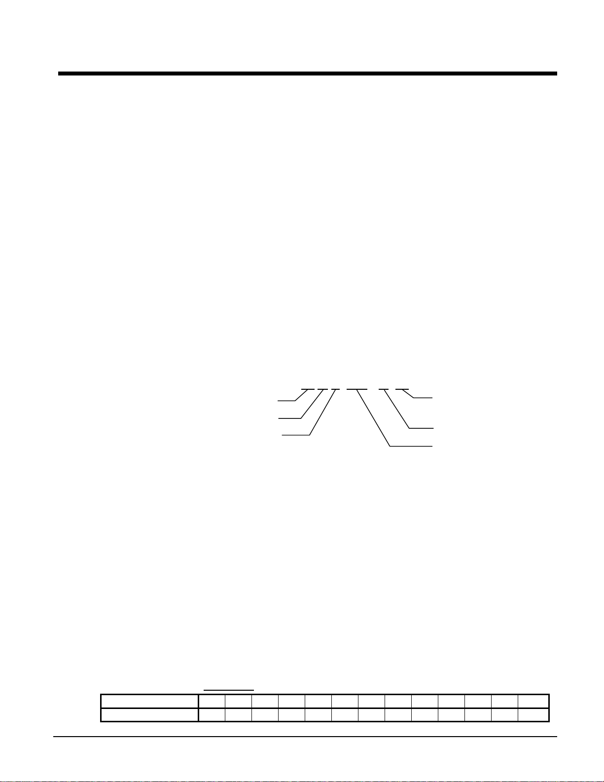
Nomenclature
W G Z 100 - A W
Water-Cooled
Global
Scroll Compressor
W = Water-Cooled Condenser
=
Design Vintage
ominal Capacity (Tons
Water Pressure Drop
Water flow rates should be maintained as closely as possible to job design values. The vessel flow
rat es mu st f al l be twe en t he mi nimu m and maxi mum values shown on the appropriate evaporator and
condenser curves.
Measure the water pressure drop through the vessels at field-installed pressure taps and check the
flow rate using the following tables. Do not include valves or strainers in these readings.
The evaporator flow rates and pressure drops shown on the following page are for full load design
purposes. The maximum flow rate and pressure drop are based on a 6-degree temperature drop.
Avoid higher flow rates with resulting lower temperature drops to prevent potential control problems
resulting from very small control bands and limited start up/shut off temperature changes.
The minimum flow and pressure drop is based on a full load evaporator temperature drop of 16degrees.
Minimum Part Load Flow Rates: This full load design minimum flow is not to be confused with
the part load minimum flow rate that must be maintained for chillers operating in variable primary
flow pumping systems. As chiller capacity drops, the flow rate is reduced proportionally. See the
following table for the part load minimum flow rates.
Table 1, Minimum Part Load
WGZ Model 030 035 040 045 050 055 060 070 080 090 100 110 120
Min.Part Load GPM
30 33 38 43 47 53 58 67 74 83 91 102 113
Flow Rates
OM WGZ-2 WGZ 030A through 120A 3
Page 4
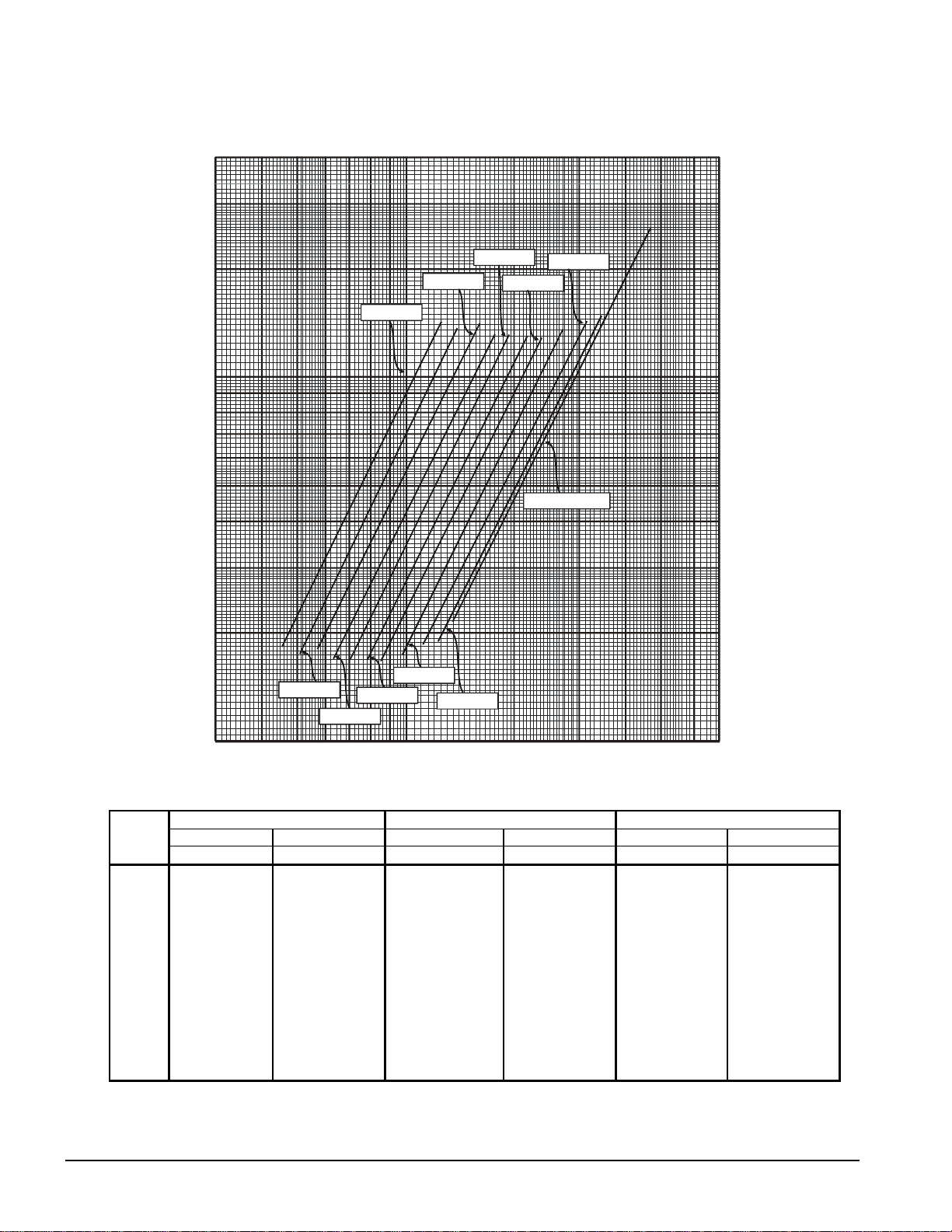
Figure 1, Evaporator Pressure Drop, WGZ 030 – WGZ 120
)
Flow Rate (L/s)
1.9 2.5 3.2 3.8 4.4 5.0 5.7 6.3
40
12.6 18.9
25.2
31.5 37.9
44.2
120
30
20
WGZ 040
WGZ 050
WGZ 060
WGZ 080
90
60
WGZ 030
Pressure Drop (kPa)
10
9
8
7
6
5
Pressure Drop (ft of water)
4
3
2
WGZ 100 - 120
30
27
24
21
18
15
12
9
6
WGZ 035
WGZ 055
WGZ 090
WGZ 045
WGZ 070
WGZ
Model
030
035
040
045
050
055
060
070
080
090
100
110
120
1
30 40 50 60 70 80 90 100 200 300 400 500 600
Flow Rate (GPM
Minimum Flow Nominal Flow Maximum Flow
Inch-Pound S.I. Inch-Pound S.I. Inch-Pound S.I.
GPM Ft. L/S kPa GPM Ft. L/S kPa GPM Ft. L/S kPa
45.5 1.85 2.87 5.54 75.8 5.15 4.78 15.40 126.3 14.31 7.97 42.77
50.3 1.76 3.17 5.27 83.8 4.90 5.29 14.65 139.7 13.62 8.81 40.70
57.7 1.83 3.64 5.46 96.2 5.07 6.07 15.15 160.3 14.08 10.12 42.10
63.7 1.71 4.02 5.10 106.1 4.74 6.69 14.17 176.8 13.16 11.16 39.35
70.0 1.70 4.41 5.08 116.6 4.72 7.36 14.12 194.3 13.12 12.26 39.21
78.2 1.70 4.93 5.08 130.3 4.72 8.22 14.10 217.2 13.11 13.70 39.17
85.8 1.67 5.41 5.00 143.0 4.65 9.02 13.90 238.3 12.91 15.04 38.60
97.9 1.75 6.18 5.24 163.2 4.87 10.30 14.54 272.0 13.51 17.16 40.40
112.3 1.86 7.09 5.56 187.2 5.17 11.81 15.45 312.0 14.36 19.68 42.92
123.5 1.91 7.79 5.70 205.9 5.29 12.99 15.82 343.2 14.71 21.65 43.96
134.9 2.14 8.51 6.39 224.9 5.94 14.19 17.74 374.8 16.49 23.65 49.29
152.9 2.75 9.65 8.21 254.9 7.63 16.08 22.79 424.8 21.18 26.80 63.31
168.8 3.34 10.65 9.99 281.3 9.29 17.75 27.76 468.8 25.80 29.58 77.11
3
700
Note: Minimum, nomin a l, and maximum flows are at a 16°F, 10°F, and 6°F chilled water temperature range respectively and at ARI tons.
4 WGZ 030A through 120A OM WGZ-2
Page 5
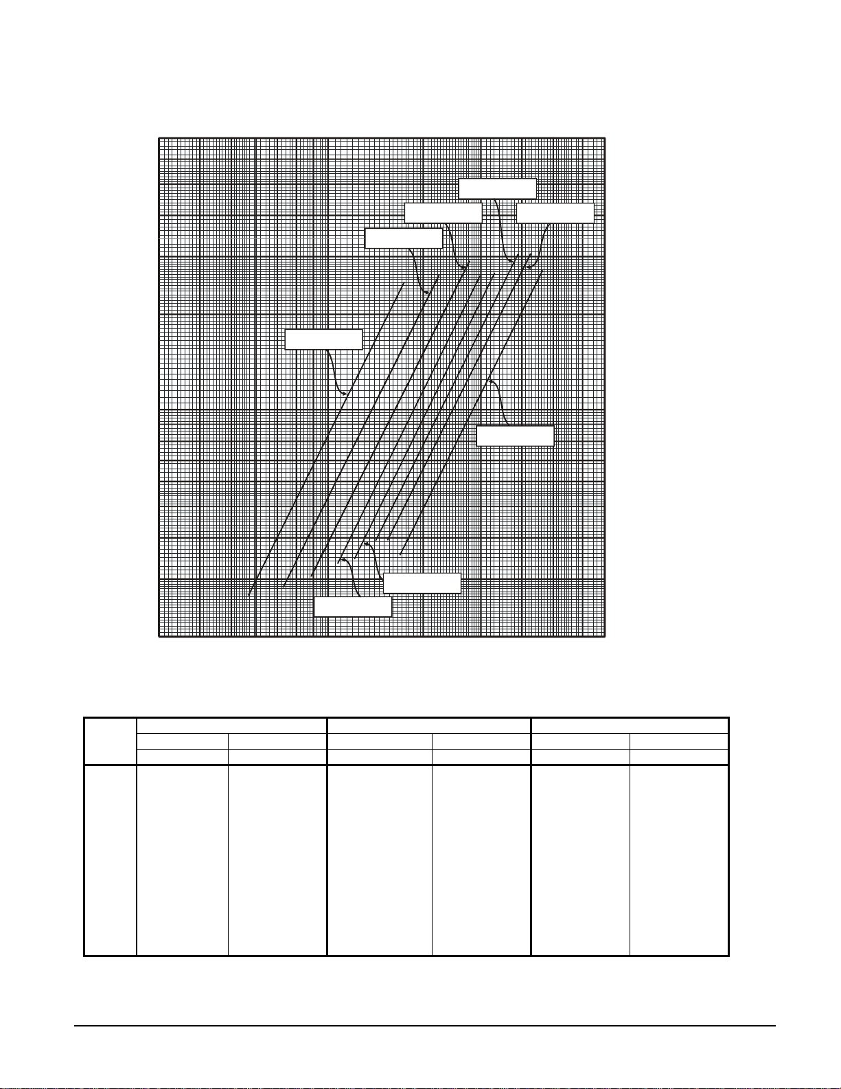
Figure 2, Condenser Pressure Drop, WGZ 030 – WGZ 120
Flow Rate (L/s)
1.9 2.5 3.2 3.8 4.4 5.0 5.7 6.3
70
60
12.6 18.9
25.2
31.5 37.9
44.2
210
180
50
40
WGZ 050, 055
WGZ 080
WGZ 090
150
120
WGZ 040, 045
30
20
90
60
Pressure Drop (kPa)
WGZ 030, 035
10
9
8
Pressure Drop (ft of water)
7
6
5
4
3
WGZ 070
WGZ 100 - 120
30
27
24
21
18
15
12
9
WGZ
Model
030
035
040
045
050
055
060
070
080
090
100
110
120
WGZ 060
2
30 40 50 60 70 80 90 100 200 300 400 500 600
Flow Rate (GPM)
6
700
Minimum Flow Nominal Flow Maximum Flow
Inch-Pound S.I. Inch-Pound S.I. Inch-Pound S.I.
GPM Ft. L/S kPa GPM Ft. L/S kPa GPM Ft. L/S kPa
56.9 2.66 3.59 7.96 94.8 7.40 5.98 22.11 158.0 20.55 9.97 61.43
62.8 3.25 3.96 9.71 104.7 9.02 6.61 26.97 174.5 25.07 11.01 74.93
72.2 2.83 4.55 8.45 120.3 7.85 7.59 23.46 200.5 21.80 12.65 65.17
79.6 3.43 5.02 10.26 132.6 9.54 8.37 28.51 221.0 26.49 13.94 79.18
87.5 3.02 5.52 9.02 145.8 8.38 9.20 25.05 243.0 23.28 15.33 69.58
97.7 3.77 6.17 11.26 162.9 10.46 10.28 31.27 271.5 29.06 17.13 86.85
107.3 3.38 6.77 10.11 178.8 9.39 11.28 28.07 298.0 26.09 18.80 77.97
122.4 3.45 7.72 10.31 204.0 9.58 12.87 28.64 340.0 26.62 21.45 79.56
140.4 3.92 8.86 11.72 234.0 10.89 14.76 32.56 390.0 30.26 24.61 90.45
154.4 3.95 9.74 11.81 257.4 10.97 16.24 32.80 429.0 30.48 27.07 91.11
168.7 3.55 10.64 10.62 281.1 9.87 17.73 29.50 468.5 27.41 29.56 81.94
191.2 4.56 12.06 13.64 318.6 12.68 20.10 37.89 531.0 35.21 33.50 105.26
211.0 5.56 13.31 16.61 351.6 15.44 22.18 46.15 586.0 42.89 36.97 128.19
OM WGZ-2 WGZ 030A through 120A 5
Page 6
Operating Limits
• Maximum allowable condenser water pressure is 232 psig (1599 kPa).
• Maximum allowable cooler water pressure is 363 psig (2509 kPa).
• Maximum design saturated discharge temperature is 140°F (60°C).
• Maximum allowable water temperature to cooler in a non-operating cycle is 100°F
(37.8°C). Maximum entering water temperature for operating cycle is 90°F (32.2°C)
(during system changeover from heating to cooling cycle).
• Minimum leaving water temperature from the cooler without freeze protection is 40°F
(4.4°C).
• Minimum entering tower condenser water temperature is 60°F (15.6°C).
Components
Figure 3, Compressor Locations
Evaporator and
423
1
Evaporator
Condenser
Connections
Circuit 2 Circuit 1
Control Panel
Table 2, Major Components
Unit
Size
030 ZR90K3 ZR90K3 ZR11M3 ZR11M3 AC250-70DQ C1010-046 OVE-20-CP100 OVE-20-CP100
035 ZR11M3 ZR11M3 ZR11M3 ZR11M3 AC250-78DQ C1010-046 OVE-20-CP100 OVE-20-CP100
040 ZR12M3 ZR12M3 ZR12M3 ZR12M3 AC250-90DQ C1010-058 OVE-20-CP100 OVE-20-CP100
045 ZR12M3 ZR12M3 ZR16M3 ZR16M3 AC250-102DQ C1010-058 OVE-30-CP100 OVE-30-CP100
050 ZR16M3 ZR16M3 ZR16M3 ZR16M3 AC250-114DQ C1010-070 OVE-30-CP100 OVE-30-CP100
055 ZR16M3 ZR16M3 ZR19M3 ZR19M3 AC250-130DQ C1010-070 OVE-30-CP100 Y929-VCP100
060 ZR19M3 ZR19M3 ZR19M3 ZR19M3 AC250-146DQ C1410-078 Y929-VCP100 Y929-VCP100
070 ZR19M3 ZR19M3 ZR250KC ZR250KC AC250-166DQ C1410-090 OVE-40-CP100 OVE-40-CP100
080 ZR250KC ZR250KC ZR250KC ZR250KC AC250-194DQ C1410-098 OVE-40-CP100 OVE-40-CP100
090 ZR250KC ZR250KC ZR300KC ZR300KC AC250-230DQ C1410-110 OVE-55-CP100 OVE-55-CP100
100 ZR300KC ZR300KC ZR300KC ZR300KC AC250-250DQ C1410-122 OVE-55-CP100 OVE-55-CP100
110 ZR300KC ZR300KC ZR380KC ZR380KC AC250-250DQ C1410-122 OVE-55-CP100 OVE-70-CP100
120 ZR380KC ZR380KC ZR380KC ZR380KC AC250-250DQ C1410-122 OVE-70-CP100 OVE-70-CP100
System #1 System #2 Expansion Valve
Comp. #1 Comp. #3 Comp. #2 Comp. #4
Evap.
Vessel
Size
Cond.
Vessel
Size
System #1 System #2
6 WGZ 030A through 120A OM WGZ-2
Page 7
Unit Configuration
The chiller unit has two refrigerant circuits, two tandem scroll compressors (total of four), a
single two-circuited brazed plate evaporator, a single two-circuited water-cooled condenser,
interconnecting refrigerant piping and a control panel with associated sensors and
transducers.
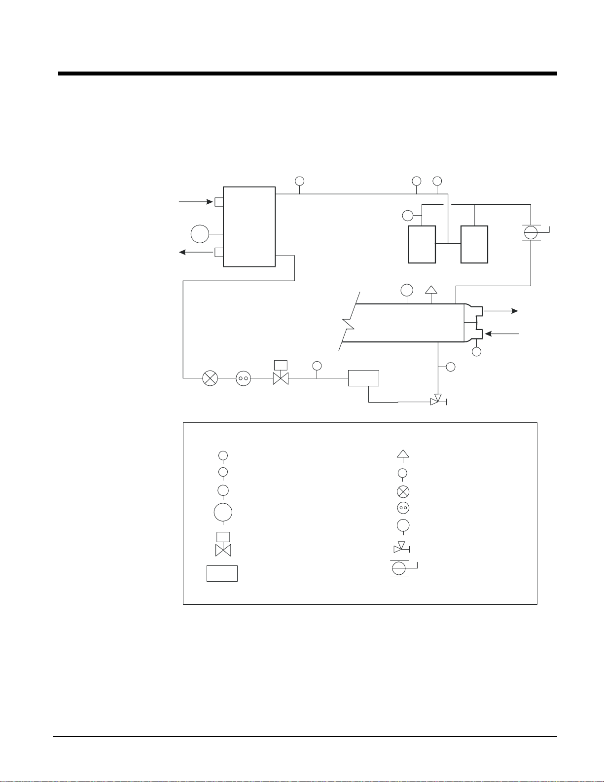
Figure 4, Schematic Piping Diagram (One of Two Circuits)
Chilled
Water
LWT
Evaporator
S
Legend:
T
T
Temperature Sensor
P
T
Pressure Transducer
P
Pressure (High Pressure Cutout)
1
T
T
P
CV
Condenser
S
F-D
S
T
SP
1
Comp
#1
Relief Valve
Schrader Fitting
Thermal Expansion Valve
Comp
#2
T
S
Condenser
Water
Temperataure Sensor, Leaving
LWT
Chilled Water Control
S
Solenoid Valve
F-D
Filter-Drier
Sight Glass / Moisture Indicator
CV
Charging Valve
Angle Valve
Ball Valve
OM WGZ-2 WGZ 030A through 120A 7
Page 8
Field Wiring Diagrams
SCO
A
A
A
N
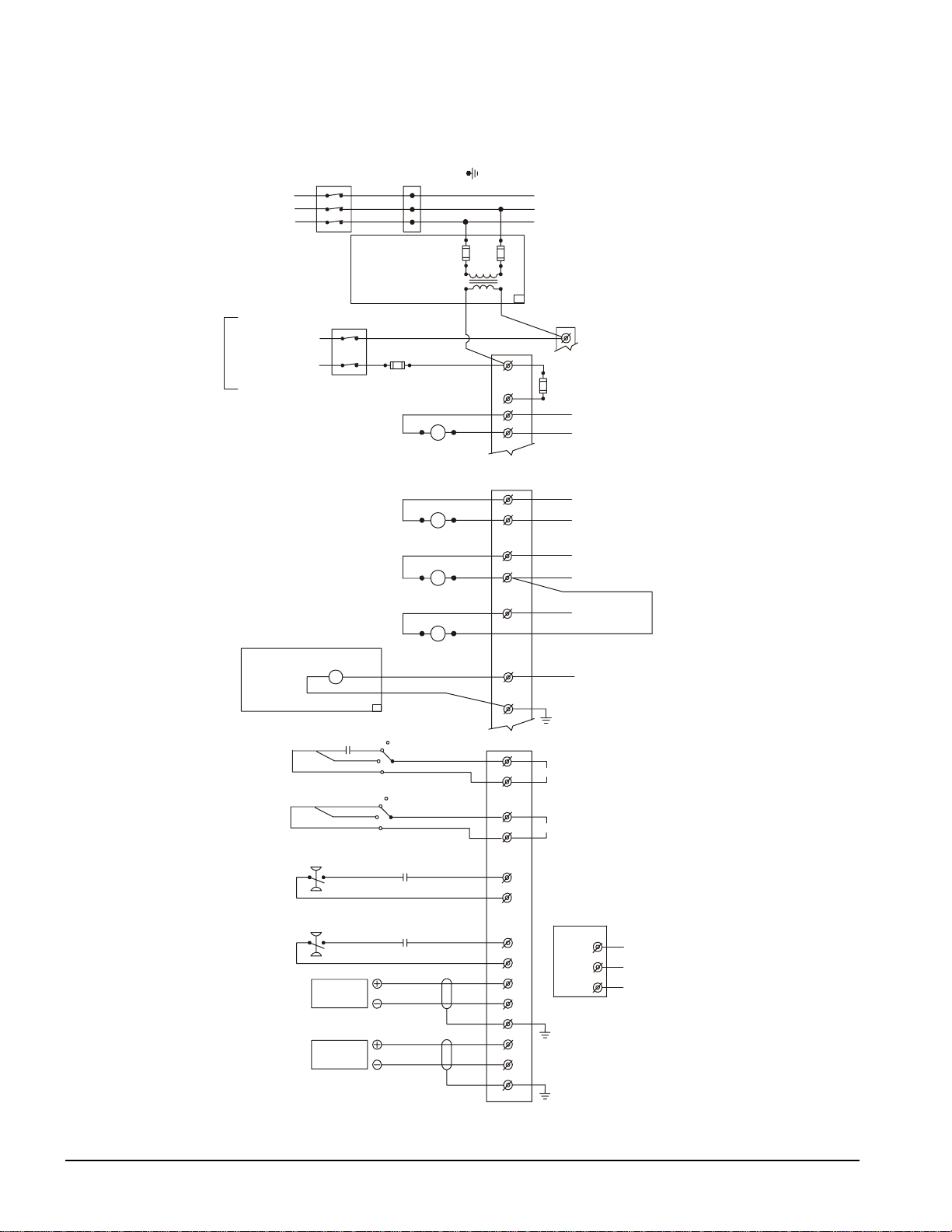
Figure 5, WGZ 030AW – 120AW Field Wiring Diagram
DI
3 PHASE
POWER
SUPPLY
FIELD
SUPPLIED
OPTION
CONTROL POWER
FACTORY SUPPLIED ALARM
FIELD WIRED
LARM BELL
OPTION
REMOTE STOP SWITCH
(BY OTHERS)
ICE MODE SWITCH
(BY OTHERS)
CHW FLOW SWITCH
--MANDATORY-(BY OTHERS)
CDW FLOW SWITCH
--MANDATORY-(BY OTHERS)
4-20 MA FOR
CHW RESET
(BY OTHERS)
4-20 MA FOR
DEMAND LIMIT
(BY OTHERS)
NNECT
(BY OTHERS)
DISCONNECT
(BY OTHERS)
N
120VAC
CDW PUMP RELA Y
(BY OTHERS)
120 VAC 1.0 AMP MAX
TOWER FAN #1 COIL
(BY OTHERS)
120 VAC 1.0 AMP MAX
ALARM BELL
RELAY
TIME
CLOCK
UNIT MAIN
TERMINAL BLOCK
FUSED CONTROL
CIRCUIT
TRANSFORMER
10A
FUSE
(BY OTHERS)
CHW PUMP RELA Y
(BY OTHERS)
120 VAC 1. 0 AMP MAX
TOWER FAN #2 COI L
(BY OTHERS)
120 VAC 1. 0 AMP MAX
OFF
UTO
ON
MANUAL
OFF
UTO
ON
MANUAL
NOR. OPEN PUMP A UX.
CONTACTS (OPTIONAL)
NOR. OPEN PUMP AUX.
CONTACTS (OPTIONAL)
GND LUG
120 VAC
TB1
CONTROLLER
J15-N08
TB1-12
J16-N09
TB1-12
J16-N10
TB2
TO COMPRESSOR(S)
TB1-20
1
CONTROL
CIRCUIT
FUSE
2
11
14
10
15
GND
40
53
42
55
IF REMOTE STOP CONTROL
897
IS USED, REMOVE LEAD 897
FROM TERM 40 TO 53.
IF ICE MODE IS USED
900
REMOVE LEAD
FROM TERM 42 TO 55.
33
43
CONTROLLER
Rx-/Tx-
41
Rx+/Tx+
53
38
48
49
GND
38
50
51
GND
N
N
N
120VAC
J11
GND
120 VAC
120 VAC
120 VAC
120 VAC
1
*
COMMUNICATIO
2
3
330258901-R4
PORT
8 WGZ 030A through 120A OM WGZ-2
Page 9
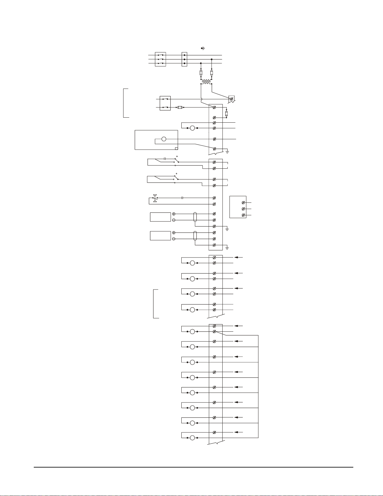
Figure 6, WGZ 030AA – 120AA Field Wiring Diagram (Remote Condenser)
UNIT MAIN
A
A
N
0
3 PHASE
FIELD
SUPPLIED
OPTION
REMOTE STOP SWITCH
NOTE:
CONDENSER FAN MOTORS
CAN ALSO BE CONTROLLED
BY PRESSURE SWITCHES
ON THE CONDENSER.
CONTROL POWER
(BY OTHERS)
ICE MODE SWITCH
(BY OTHERS)
CHW FLOW SWITCH
4-20 MA FOR
CHW RESET
(BY OTHERS)
4-20 MA FOR
DEMAND LIMIT
(BY OTHERS)
330259001-R4
DISCONNECT
(BY OTHERS)
POWER
SUPPLY
FUSED CONTROL
TRANSFORMER
DISCONNECT
(BY OTHERS)
N
120VAC
FACTORY SUPPLIED ALARM
FIELD WIRED
ALARM BELL
OPTION
ALARM BELL RELAY
TIME
CLOCK
ON
UTO
ON
--MANDATORY--
(BY OTHERS)
LIQUID LINE #1 SOLENOID
LIQUID LINE #2 SOLENOID
OPTIONAL
HOT GAS BYPASS #1 SOLENOID
HOT GAS BYPASS #2 SOLENOID
FAN MOTOR #1 COIL
FAN MOTOR #2 COIL
FAN MOTO R #3 COIL
FAN MOTO R #4 COIL
FAN MOTOR #5 COIL
FAN MOTO R #6 COIL
FAN MOTO R #7 COIL
FAN MOTOR #8 COIL
TERMINAL BLOCK
CIRCUIT
10A
FUSE
(BY OTHERS)
CHW PUMP RELAY
(BY OTHERS)
120 VAC 1.0 AMP MAX
OFF
UTO
MANUAL
OFF
MANUAL
NOR. OPEN PUMP AUX.
CONTACTS (OPTIONAL)
24 VAC AMP MAX
24 VAC AMP MAX
24 VAC AMP MAX
24 VAC AMP MAX
(BY OTHERS)
120 VAC 1.0 AMP MAX
(BY OTHERS)
120 VAC 1.0 AMP MAX
(BY OTHERS)
120 VAC 1.0 AMP MAX
(BY OTHERS)
120 VAC 1.0 AMP MAX
120 VAC 1.0 AMP MAX
120 VAC 1.0 AMP MAX
(BY OTHERS)
120 VAC 1.0 AMP MAX
(BY OTHERS)
VAC 1.0 AMP MAX
12
120
VAC
(BY OTHERS)
(BY OTHERS)
GND LUG
TB1
1
2
11
14
10
15
TB2
40
53
42
55
33
43
38
48
49
38
50
51
TB3
62
65
63
65
67
70
68
70
CONTROLLER
J15-N08
TB1-12
J16-N09
J16-N010
J16-N011
J18-N013
J22-N016
J22-N017
J22-N018
TO COMPRESSOR(S)
TB1-20
CONTROL
CIRCUIT
FUSE
120 VAC
N
120VAC
GND
IF REMOTE STOP CONTROL
897
IS USED, REMOVE LEAD 897
FROM TERM 40 TO 53.
IF ICE MODE IS USED
900
REMOVE LEAD
FROM TERM 42 TO 55.
CONTROLLER
J11
GND
N
N
N
N
N
1
2
3
24 VAC
24 VAC
24 VAC
24 VAC
120 VAC
120 VAC
120 VAC
120 VAC
120 VAC
120 VAC
120 VAC
120 VAC
Rx-/TxRx+/Tx+
GND
GND
*
COMMUNICATIO
PORT
OM WGZ-2 WGZ 030A through 120A 9
Page 10
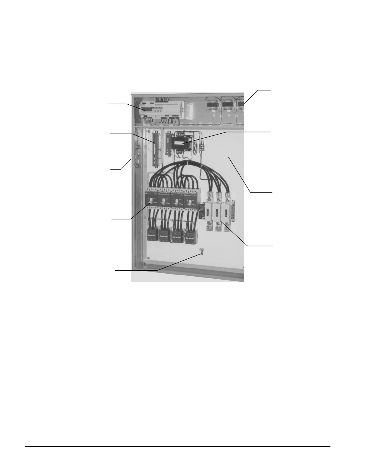
Control Panel Layout
Figure 7, Typical Control Panel
MicroTech II Unit
Controller
(3) 24V Controller
Transformers
Terminal Strips
S1, PS1, PS2
(4) Compressor
Grounding Lug
Switches
Contactors
110V Control
Space for
Optional Circuit
Breakers and
Multi-point
Connection
Disconnect
Switch
NOTES:
1. Additional space provided in the upper right section for extra components required for
optional multiple point power connection and optional circuit breakers.
2. Front door has opening on top for access to the MicroTech II controller for viewing
display and making keypad entries without opening the panel door.
Motor Protection Module
The motor protection system consists of an external control module, located on each
compressor, connected to a series of thermistors located in the motor windings and the
compressor discharge port. If the windings experience an over-temperature condition or the
discharge temperature is excessive, the module will trip and shut off the compressor for a
30-minute time delay.
10 WGZ 030A through 120A OM WGZ-2
Page 11

Start-Up and Shutdown
Pre Start-up
1. The chilled-water system should be flushed and cleaned. Proper water treatment is
required to prevent corrosion and organic growth.
2. With main disconnect open, check all electrical connections in control panel and starter
to be sure they are tight and provide good electrical contact. Although connections are
tightened at the factory, they can loosen enough in shipment to cause a malfunction.
3. Check and inspect all water piping. Make sure flow direction is correct and piping is
made to correct connection on evaporator and condenser.
4. Open all water flow valves to the condenser and evaporator.
5. Flush the cooling tower and system piping to be sure the system is clean. Start
evaporator pump and manually start condenser pump and cooling tower. Check all
piping for leaks. Vent the air from the evaporator and condenser water circuit, as well
as from the entire water system. The cooler circuit should contain clean, treated, noncorrosive water.
6. Check to see that the evaporator water thermostat sensor is securely installed.
7. Making sure control stop switch S1 is open (off) and pumpdown switches PS1 and PS2
are on “manual pumpdown,” place the main power and control disconnect switches to
“on.” This will energize the crankcase heaters. Wait a minimum of 12 hours before
starting the unit.
8. Check compressor oil level. Prior to start-up, the oil level should cover at least onethird of the oil sight glass located in the equalizing line between the compressors or on
the compressor.
9. Note the water pressure drop across evaporator and condenser on pages Error!
Bookmark not defined. and Error! Bookmark not defined. and check that water
flow is correct per the system design flow rates.
10. Check the actual line voltage to the unit to make sure it is the same as called for on the
compressor nameplate, within + 10%, and that phase voltage unbalance does not
exceed 3%. Verify that adequate power supply and capacity is available to handle load.
11. Make sure all wiring and fuses are of the proper size. Also make sure that all interlock
wiring is completed per McQuay diagrams.
12. Verify that all mechanical and electrical inspections by code authorities have been
completed.
13. Make sure all auxiliary load and control equipment is operative and that an adequate
cooling load is available for initial start-up.
Start-up
1. Open the compressor discharge shutoff valves until backseated. Always replace valve
seal caps.
2. Open the two manual liquid line shutoff valves.
3. Check to see that the unit circuit breakers are in the “off” position.
4. Check to see that the pumpdown switches, PS1 and PS2, are in the “manual
pumpdown” position and the control system switch S1 is in the “off” position.
5. Put the main power and control circuit disconnects to the “on” position.
OM WGZ-2 WGZ 030A through 120A 11
Page 12

6. Verify crankcase heaters have operated for at least 12 hours prior to start-up.
Crankcase should be warm to the touch.
7. Check that the MicroTech II controller is set to the desired chilled water temperature.
8. Start the system auxiliary equipment for the installation by turning on the time clock,
ambient thermostat and/or remote on/off switch and water pumps.
9. Check resets of all equipment protection controls.
10. Switch on the unit circuit breakers.
11. Set pumpdown switches PS1 and PS2 to “auto” for restart and normal operation.
12. Start the system by setting the system switch S1 to on.
13. After running the unit for a short time, check the oil level in each compressor
crankcase, rotation of condenser fans (if any), and check for flashing in the refrigerant
sight glass.
14. After system performance has stabilized, it is necessary that the “Compressorized
Equipment Warranty Form” (Form No. 206036A) be completed to establish
commencement of the warranty period. Be sure to list the pressure drop across both
vessels. This form is shipped with the unit and after completion should be returned to
the McQuayService Department through your sales representative.
Weekend or Temporary Shutdown
Move pumpdown switches PS1 and PS2 to the “manual pumpdown” position. After the
compressors have pumped down, turn off the chilled water pump. Note: With the unit in
this condition, it will not restart until these switches are turned back on. The unit has onetime pumpdown. It is important that the compressors pump down before the water flow to
the unit is interrupted to avoid freeze-up in the evaporator.
Leave S1 on and power to the unit so that the crankcase heaters will remain energized.
Start-up after Temporary Shutdown
1. Start the water pumps.
2. With the control system switch S1 in the “on” position, move the pumpdown switches
PS1 and PS2 to the “auto pumpdown” position.
3. Observe the unit operation for a short time, noting unusual sounds or possible cycling
of compressors.
4. Check compressor crankcase heaters.
Extended Shutdown
1. Close the manual liquid line shutoff valves.
2. After the compressors have pumped down, turn off the water pumps.
3. Turn off all power to the unit.
4. Move the control service switch S1 to the “off” position.
5. Close the discharge shutoff valves on the compressor(s) and the liquid outlet valves at
the condenser.
6. Tag all opened disconnect switches to warn against start-up before opening the
compressor suction and discharge valves.
7. Drain all water from the unit evaporator, condenser, and chilled water piping if the unit
is to be shut down during the winter and exposed to below freezing temperatures. Do
not leave the vessels or piping open to the atmosphere over the shutdown period.
12 WGZ 030A through 120A OM WGZ-2
Page 13
Start-up after Extended Shutdown
1. Inspect all equipment to see that it is in satisfactory operating condition.
2. Remove all debris that has collected on the surface of the condenser coils (remote
condenser models) or check the cooling tower, if present.
3. Open the compressor discharge valves until backseated. Always replace valve seal caps.
4. Open the manual liquid line shutoff valves.
5. Check circuit breakers. They must be in the “off” position.
6. Check to see that the pumpdown switches PS1 and PS2 are in the “manual shutdown”
position and the control system switch S1 is in the “off” position.
7. Put the main power and control circuit disconnects to the “on” position.
8. Allow the crankcase heaters to operate for at least 12 hours prior to start-up.
9. Start the chilled water pump and purge the water piping as well as the evaporator in the
unit.
10. Start the system auxiliary equipment for the installation by turning on the time clock,
ambient thermostat and/or remote on/off switch.
11. Check that the MicroTech II controller is set to the desired chilled water temperature.
12. Check resets of all equipment protection controls.
13. Switch the unit circuit breakers to “on.”
14. Start the system by setting the system switch S1 to “on.”
CAUTION
Most relays and terminals in the control center are powered when S1 is
closed and the control circuit disconnect i s on. Therefore, do not close S1
until ready for start-up or serious equipment damage can occur.
15. Set pumpdown switches PS1 and PS2 to the “auto pumpdown” position for restart and
normal operation.
16. After running the unit for a short time, check the oil level in the compressor oil sight
glass or in the compressor’s equalizing lines for flashing, indicating possible refrigerant
in the oil.
Low Ambient Start
The low ambient start logic is for starting units with remote air-cooled condensers during
periods of low ambient air temperatures.
A low ambient start takes place if the saturated condenser temperature is less than 85.0°F
when the first compressor starts. The low ambient start is active for a time defined by the
Low OAT Start Timer set point. This set point is found on screen three in the alarm set
points menus.
During the low ambient start, the freezestat logic for the low-pressure stop alarm and the
low-pressure events are disabled. The low-pressure stop alarm can still be triggered if the
evaporator pressure drops below 5.0 psi at any time while the circuit is in the ‘Run’ state.
Also, during the low ambient start, the second compressor is not allowed to start. The
evaporator pressure is checked at the end of the low ambient start time frame. If the
pressure is less than the low pressure unload set point, then the low ambient start is not
successful and the compressor will shut off. This will not be a manual reset alarm until
three consecutive attempts have failed. The circuit alarm triggered after the third failed
OM WGZ-2 WGZ 030A through 120A 13
Page 14
F
F
F
F
attempt is a Low OAT Restart fault. The Low OAT Restart faults are Circuit alarms so each
circuit will attempt to start either compressor three times before the Low OAT Restart fault
is indicated.
Fan High Ambient Rapid Start
The following logic exists to get condenser fans started earlier than normal during unit
starts with warm ambient air temperatures.
• If the outside air temperature higher than 75.0°F the condenser fan staging logic
changes to bring on the first fan on when the condenser pressure is greater than 140 psi.
• The standard condenser fan staging logic would start the first condenser fan when the
condenser pressure is higher than 200.0 psi.
• The last condenser fan on each circuit will not shut down until the condenser pressure
drops below 140.0 psi regardless of the outside air temperature
Sequence of Operation
The following sequence of operation is typical for WGZ water chiller models. The
sequence can vary slightly depending upon options.
Compressor Heaters
With the control circuit power on and the control stop switch S1 off, 115V power is applied
through the control circuit fuse Fl to the compressor crankcase heaters HTR1, HTR2,
HTR3, and HTR4.
Start-up/Compressor Staging
When compressors start and stop.
Stage Up Temp is the LWT temperature at which the next compressor to start will stage up
(start) after at least one compressor on the unit has started and is running.
Start Up Temp is the LWT at which the first compressor starts. The start up temperature
equals the stage up temperature plus the Start Delta temperature. A high Start Delta will
keep the unit off longer and reduce unit cycling at low loads. However, this high Start
Delta will cause a larger excursion from the LWT setpoint before the unit starts.
Stated another way, the Start Delta is the number of degrees above the Evap LWT setpoint,
plus ½ the Dead Band, that determines when the first compressor starts. The Start Delta is
in effect for only the first start after all compressors have been off. Additional compressor
starts and stops are determined by the LWT in respect to the dead band only. The dead
band is automatically set of 30% of the EvapDeltaT selected in menu 3. The following
sequence would occur for the settings shown below:
EvapDelta T=10.0°F Dead Band=3.0°F StartDelta=5.0°F StopDelta=2.0°F
LWT=40.0°F
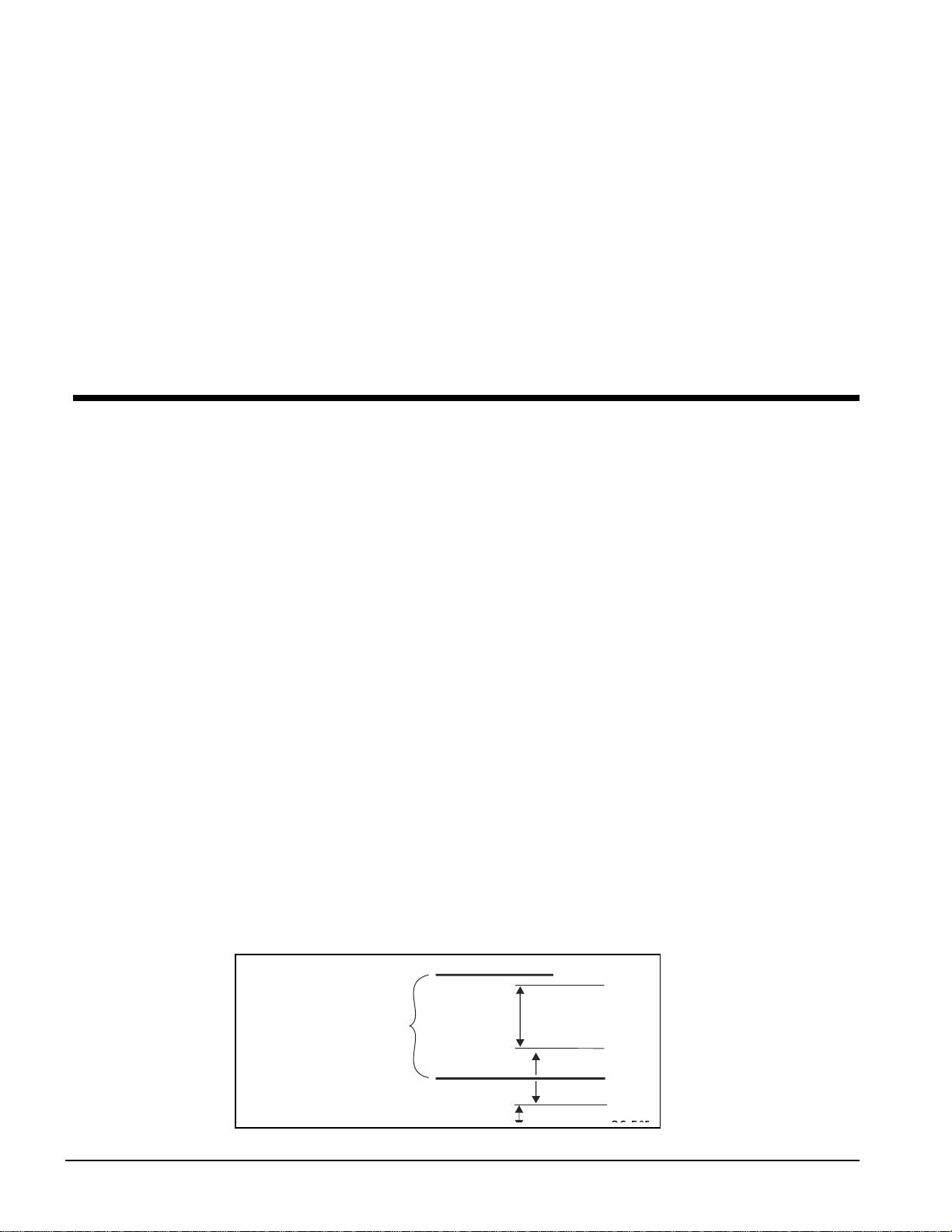
Figure 8, Staging/Starting Temperatures
EWT
Evap Delta-T Set
LWT Set
50.0°F
10.0°F
40.0°F
Start Del ta T
½DB
½DB
46.5°
41.5°
40.0°
38.5°
For a warm start-up (no
compressors running), the
first compressor will start
at any temperature above
46.5°F. Each subsequent
compressor will start after
the Stage Up Timer has
timed out and if the
temperature is above the
14 WGZ 030A through 120A OM WGZ-2
Page 15
dead band, 41.5°F in this case. If the LWT stays above 41.5°F, all of three remaining
compressors will eventually stage on after the Stage Up Timer times out between each
stage.
At some point, the chilled water temperature will be dropping and begin to approach the
point when compressors should begin staging off, which is the LWT setpoint minus ½ of
the Dead Band, 38.5°F in this case. If the LWT remains below LWT setpoint minus ½
Dead Band and the Stage Down Timer times out, additional compressor will stage off. The
last compressor will stage off when the LWT falls below the LWT Setpoint minus ½ the
Dead Band minus the Stop Delta T. The stop Delta T is in effect for only the last
compressor running.
If the temperature climbs above 38.5°F all running compressors will remain on. No
compressor staging occurs within the Dead Band. The next-on compressor will start when
the chilled water temperature reaches 41.5°F and the Stage Up Timer times out.
However, in some circumstances this methodology can cause the LWT to drop to
dangerously low levels, with the evaporating temperature below the freeze point, before
stopping. In the example shown in Figure 8, the Shutdown Temp (last compressor off)
would be 36°F.
This would result in a refrigerant evaporating temperature approaching freezing, so the rule
is amended to read:
If the Cool Leaving Water Temperature (LWT) set point is less than half the
Control Band above 39.0° F the Stage Down temperature is calculated as:
Stage Down Temperature = Cool LWT – (Cool LWT - 39.0
Shutdown Temperature = Cool LWT – (Cool LWT - 39.0
°
F), and the
°
F) – Stop Delta T
This keeps the Stage Down Temp above 39°F and the Shutdown Temp above 36°F, as the
maximum Stop Delta T allowed is 3-degrees.
Which compressor starts and stops. One compressor per circuit will start before starting
the second compressor on any circuit. In other words, the compressor with the lowest
number of starts will start first. The compressor with the lowest number of starts on the
other circuit will start next, so that one compressor on each circuit will be running. The
third compressor on will be the compressor on either circuit with the fewest starts. The
remaining compressor will be the last on. If a circuit is unavailable for any reason, the
second compressor. on the operating circuit will stage on. Only two compressors (on the
one circuit) will be operating.
There is a 150 second delay after power-up before any compressor is allowed to start.
When staging down, one compressor on each circuit will be left on until each circuit has
only one compressor running. In other words, the compressor, on either circuit, with the
most run-hours will stop first. The compressor with the most run-hours on the other circuit
will stop next. One compressor on each circuit will be running. The third compressor off
will be the one, on either circuit, with the most run-hours. The remaining compressor will
be the last off. See the following description of pumpdown.
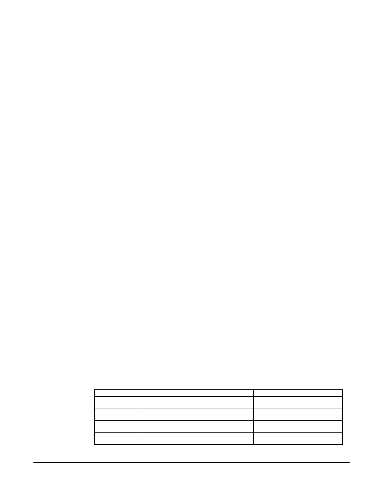
Table 3, Staging in Cool and Glycol Mode
Description Occurs When: Action Taken
Stage #1 ON
(See Notes Below)
Stage #2 ON After Stage Up Delay times out then, LVG Evap
Stage #3 ON After Stage Up Delay times out, then LVG Evap
Stage #4 ON After Stage Up Delay times out then, LVG Evap
Lvg Evap T > Evap LWT SP + (DB/ 2) + S t artup
Delta T
T > Evap LWT SP + (DB/2)
T > Evap LWT SP + (DB/2)
T > Evap LWT SP + (DB/2)
Available compressor with l east
starts, ON
Available compressor on the other
circuit with least starts, ON
Available compressor on ei ther circuit
with least starts, ON
Remaining compressor, ON
Continued next page.
OM WGZ-2 WGZ 030A through 120A 15
Page 16
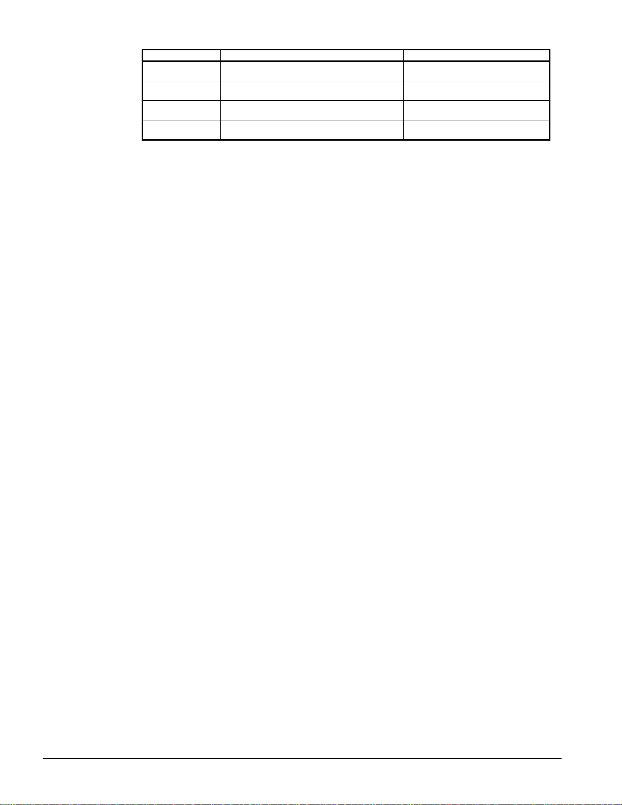
Description Occurs When: Action Taken
Stage #4 OFF After Stage Down Delay times out then, LVG
Evap T < Evap LWT SP – (CB/2)
Stage #3 OFF After Stage Down Delay times out then, LVG
Evap T < Evap LWT SP – (DB/2)
Stage #2 OFF After Stage Down Delay times out then, LVG
Evap T < Evap LWT SP – (DB/2)
Stage #1 OFF After Stage Down Delay times out then, LVG
Evap T < Evap LWT SP – (DB/2)-StopDelta T
Note 1: DB (Dead Band) = Evap W ater Delta T x .3
Compressor with most run hours,
OFF
Compressor on the other ci rcuit with
most run hours, OFF
Compressor on either circuit with
most run hours, OFF
Remaining compressor, OFF
Manual Compressor Disable Logic
Logic is available that allows the operator to manually enable and disable compressors.
When a compressor is disabled, it is considered unavailable to start in the staging logic.
This allows a damaged compressor to be taken offline while the remaining compressor can
still provide some cooling
• The Compressor Disable set points are found on Compressor Set Points screens three
and four.
• A running compressor cannot be disabled until it has been shutdown.
• If all of the compressors on a circuit are disabled, then the circuit will be disabled.
• If both circuits have all of their compressors disabled, then the Unit State will remain
Off
Automatic Pumpdown
WGZ units are equipped with single pumpdown control. When the last compressor running
on either circuit is ready to shut off, the liquid line solenoid valve (LLSV) is closed first
and the compressor continues to run until the pumpdown pressure is reached, at which time
the compressor shuts off. The shut off pressure is set at 15 psi below the Low Evaporator
pressure Unload setpoint.
When the first compressor on a circuit starts, the LLSV opens simultaneously.
Manual Pumpdown
When the Pumpdown Switch is in the pumpdown position, Compressor #3 or #4
(depending on circuit) will shut off. Then the Liquid Line and Hot Gas Bypass Valves will
close. The operating compressor will pump out the refrigerant. When the Suction Pressure
is at 40 psig, the compressor will stop.
Chilled Water and Condenser Water Pumps
The chiller MicroTech II controller can be programmed to start and stop the system chilled
water and condenser water pumps. They may also be controlled by the BAS or manually.
Programming directions and the sequence of operation can be found beginning on page 30.
Cooling Tower Control
The cooling tower fans and/or the tower bypass valve can be controlled by the MicroTech II
controller. This provides a simple and direct method to control the unit’s discharge
pressure. Programming directions and the sequence of operation can be found on page 44.
Some means of discharge pressure control must be installed if the condenser water
temperature can fall below 60°F (16°C).
16 WGZ 030A through 120A OM WGZ-2
Page 17

Condenser Fan Control
Model AA chillers equipped with air-cooled or evaporative-cooled condensers usually
require some form of discharge pressure control. The MicroTech II controller can be
programmed to provide this function by cycling condenser fans based on the unit discharge
pressure. Directions on the pressure settings can be found on page 44.
ICE
In ICE mode, the compressors stage to 100% load until the LWT is less than the ICE LWT
SP. Then Compressors #3 and #4 shut down. Following that, Compressors #1 and #2 shut
down after going through normal pumpdown on both circuits. There is a programmable,
start-to-start, Ice Mode Start Delay that limits the frequency of starts when in the ice mode.
The timer can be manually cleared to force a restart.
OM WGZ-2 WGZ 030A through 120A 17
Page 18

MicroTech II Controller
Controller Software Version
This manual is based on software version WGZD20102B. The “02B” is the version
descriptor. The version installed in a unit can be viewed by pressing the MENU and
ENTER keys simultaneously. Then pressing MENU to return to the regular menu screen.
General Description
The MicroTech II controller’s state-of-the-art design will not only permit the chiller to run
more efficiently but will also simplify troubleshooting if a system failure occurs. Every
MicroTech II controller is programmed and tested prior to shipment to assist in a troublefree start-up. The MicroTech II controller can be used to cycle fans on remote air-cooled
condensers for head pressure control when the setpoint Water Cooled=N is selected in one
of the setpoint menu screens. Water Cooled=Y sets the chiller for operation with the watercooled condenser.
Operator Friendly
The MicroTech II controller menu structure is separated into three distinct categories,
which provide the operator or service technician with a full description of 1) current unit
status, 2) control parameters (setpoints), and 3) alarms. Security protection prevents
unauthorized changing of the setpoints and control parameters.
The MicroTech II controller continuously performs self-diagnostic checks, monitoring all
system temperatures, pressures and protection devices, and will automatically shutdown a
compressor, a refrigerant circuit or the entire unit should a fault occur. The cause of the
shutdown and date stamp are retained in memory and can be easily displayed in plain
English for operator review, which is an extremely useful feature for troubleshooting. In
addition to displaying alarm diagnostics, the MicroTech II chiller controller also provides
the operator with a warning of pre-alarm conditions.
Staging
The four scroll compressors are staged on and off as a function of leaving chilled water
temperature, number of starts and run-hours. See Sequence of Operation.
Equipment Protection
The unit is protected by alarms that shut it down and require manual reset, and also by limit
alarms that limit unit operation in response to some out-of-limit condition. Shut down
alarms activate an alarm signal that can be wired to a remote device.
Unit Enable Selection
Enables unit operation from local keypad or digital input.
Unit Mode Selection
Selects standard cooling, ice, glycol, or test operation mode.
18 WGZ 030A through 120A OM WGZ-2
Page 19

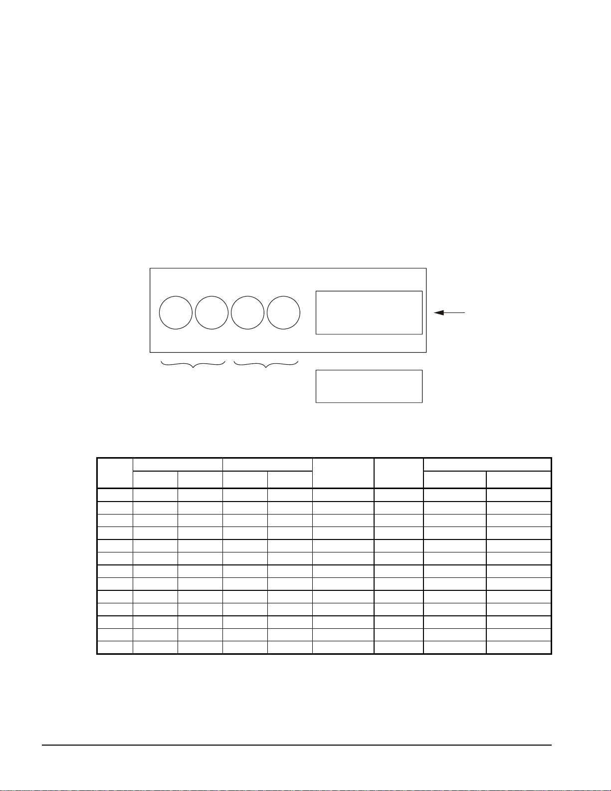
Keypad/Display
A 4-line by 20-character/line liquid crystal display and 6-key keypad is mounted on the unit
controller. Its layout is shown below.
Figure 9, Keypad and Display in MENU Mode
Air Condi ti oni ng
<
ALARM
<
VIEW
<
SET
Menu Key Key to Screen
Arrow Keys
"Enter" Key
The four arrow keys (UP, DOWN, LEFT, RIGHT) have three modes of use.
1. Scroll between data screens as indicated by the arrows (default mode).
2. Select a specific data screen in a hierarchical fashion using dynamic labels on the right
side of the display (this mode is entered by pressing the MENU key).
3. Change field values in edit mode according to the following table:
LEFT Default
RIGHT Cancel
UP Increment
DOWN Decrement
These four edit functions are indicated by one-character abbreviation on the right side of
the display (this mode is entered by pressing the ENTER key).
Inputs/Outputs
Table 4, Analog Inputs
C1 = Refrigerant Circuit #1, C2 = Refrigerant Circuit #2, UT = Unit
# Description Type Signal Source Range
1 Evaporator Refrigerant Pressure #1 C1 0.5 – 4.5 VDC (NOTE 1) 0 to 132 psi
2 Evaporator Refrigerant Pressure #2 C2 0.5 – 4.5 VDC (NOTE 1) 0 to 132 psi
3 Condenser Refrigerant Pressure #1 C1 0.5 – 4.5 VDC (NOTE 1) 3.6 to 410 psi
4 Leaving Evaporator Water Temperature UT
Condenser Entering or Outside
5
Ambient Temperature (NOTE 2)
6 Condenser Refrigerant Pressure #2 C2 0.1 to 0.9 VDC
7 Reset of Leaving Water Temperature UT 4-20 mA Current 0-(10 to 60°F)
8 Demand Limit UT 4-20 mA Current 0-100 % Load
9 Compressor Suction Temperature #1 C1
10 Compressor Suction Temperature #2 C2
NOTES:
1. Value at the converter board input. Value at the converter board output is 0.1 VDC – 0.9 VDC.
2. If Water Cooled = Y, then Entering Condens er. If Water Cooled = N, then Outside Ambient.
UT
Thermister (10k at 77°F,
25°C)
Thermister (10k at 77°F,
25°C)
Thermister (10k at 77°F,
25°C)
Thermister (10k at 77°F,
25°C)
-58 to 212°F
-58 to 212°F
3.6 to 410 psi
-58 to 212°F
-58 to 212°F
OM WGZ-2 WGZ 030A through 120A 19
Page 20

Table 5, Analog Outputs
# Description Output Signal Range
1 Cooling Tower Bypass Valve Position 0 to 10 VDC 0 to 100% Open
2 Cooling Tower VFD Speed 0 to 10 VDC 0 to 100%
Table 6, Digital Inputs
C1 = Refrigerant Circuit #1, C2 = Refrigerant Circuit #2, UT = Unit
# Description Type Signal Signal
1 Unit OFF Switch UT 0 VAC (Stop) 24 VAC (Auto)
2 Pump Down Switch #1 C1 0 VAC (Stop) 24 VAC (Start)
3 Evaporator Water Flow Switch UT 0 VAC (No Flow) 24 VAC (Flow)
4 Motor Protection #1 C1 0 VAC (Fault) 24 VAC (No Fault)
5 Open
6 Pump Down Switch #2 C2 0 VAC (Stop) 24 VAC (Start)
7 Motor Protection #2 C2 0 VAC (Fault) 24 VAC (No Fault)
8 Open
9 Phase Voltage Fault #1 (See Note 1) C1 0 VAC (Fault) 24 VAC (No Fault)
10 Phase Voltage Fault #2 (See Note 1) C2 0 VAC (Fault) 24 VAC (No Fault)
11 Ground Fault Prot. #1 (See Note 2) C1 0 VAC (Fault) 24 VAC (No Fault)
12 Ground Fault Prot. #2 (See Note 2) C2 0 VAC (Fault) 24 VAC (No Fault)
13 Remote Start/Stop UT 0 VAC (Stop) 24 VAC (Start)
14 Condenser Water Flow Switch UT 0 VA C (No Fl ow) 24 VAC (Flow)
15 Mechanical High Pressure #1 C2
16 Mechanical High Pressure #2 C2
17 Ice Mode Switch UT 0 VAC (Normal) 24 VAC (Ice)
18 Open
Note 1: See Equipment Protection Alarms Table for “Phase Voltage Protection”. Units with single point
electrical connection will have one PVM with Inputs 9 and 10 wired together. Units with multiple point
connection will have two PVM’s with Input 9 for Electrical Circuit #1 and Input 10 for Electrical Circuit #2.
Note 2: See Equipment Protection Alarms Table for “Ground Fault Protection”. Units with single point
electrical connection will have one GFP with Inputs 11 and 12 wired together. Units with multiple point
connection will have two GFP’s with Input 11 for Electrical Circuit #1 and Input 12 for Electrical Circuit #2.
0 VAC (High
Pressure/Off)
0 VAC (High
Pressure/Off)
24 VAC (OK )
24 VAC (OK )
Table 7, Digital Outputs
C1 = Refrigerant Circuit #1, C2 = Refrigerant Circuit #2, UT = Uni t
# Description Type Load Output OFF Output ON
1 Alarm
2 E vaporat or Water Pump UT Pump Contactor Pump OFF Pump ON
Condenser Fan #1 – Water Cooled
3
= N / Condenser Water P ump –
Water Cooled = Y
4 Motor Control Relay #1 = Compr#1 C1 Starter Compressor OFF Compressor ON
5 Motor Control Relay #3 = Compr#3 C1 Starter Compressor OFF Compressor ON
Condenser Fan #3– Water Cooled
6
=N /Tower Fan #2-Water Cooled=Y
7 Li qui d Li ne #1 C1 Solenoid Cooling OFF Cooling ON
Condenser Fan #2 – Water Cooled
8
=N /Tower Fan #1-Water Cooled=Y
9 Motor Control Relay #2 = Compr#2 C2 Starter Compressor OFF Compressor ON
10 Motor Control Relay #4 = Compr#4 C2 Starter Compress or OFF Compressor ON
11 Condenser Fan #4 C2 Fan Contactor Fan OFF Fan ON
12 Liquid Line #2 C2 Solenoid Cooling OFF Cooling ON
13 Condenser Fan #5 C1 Fan Contactor Fan OFF Fan ON
14 Hot Gas Bypass #1 C1 Solenoid Cooling OFF Cooling ON
15 Hot Gas Bypass #2 C2 Solenoid Cooling OFF Cooling ON
16 Condenser Fan #6 C2 Fan Contactor Fan OFF Fan ON
17 Condenser Fan #7 C1 Fan Contactor Fan OFF Fan ON
18 Condenser Fan #8 C2 Fan Contactor Fan OFF Fan ON
C1,C2,
UT
C1 /
UT
C1 /
UT
C2 /
UT
Alarm Indicator Alarm OFF Alarm ON
Fan Contactor/
Pump Contactor
Fan Contactor Fan OFF Fan ON
Fan Contactor Fan OFF Fan ON
Fan OFF Fan ON
20 WGZ 030A through 120A OM WGZ-2
Page 21

Setpoints
The following parameters are remembered during power off, are factory set to the Default
value, and can be adjusted to any value in the Range column.
The PW (password) column indicates the password level that must be active in order to
change the setpoint. Passwords are as follows:
O = Operator [0100]
M = Manager [2001]
Table 8, Setpoints
Description Default Range PW
Unit Enable OFF OFF, ON O
Unit Mode COOL COOL, COOL w/Glycol, ICE w/Glycol O
Control source DIGITAL INPUT KEYPAD, B A S , DIGITAL INPUT O
Available Modes COOL COOL, COOL w/Glycol, /ICE w/Glycol M
XXX Display Units
XXX Language ENGLISH ENGLISH, (TBD) O
BAS Protocol NONE NONE, BACnet, LonWorks, Modbus M
Ident Number 001 001-999 M
Baud Rate 9600 1200, 2400, 4800, 9600, 19200 M
Evap LWT (COOL & GLYCOL)
Ice LWT (ICE )
Evap Delta T
Startup Delta T
Stop Delta T
Max Pulldown Rate
Low Ambient Lockout (Water-cooled = No)
Demand Limit Off Off, On M
* Water Cooled N N,Y M
* Refrigerant Select None R22, R407c -* Phase Voltage Protect i on N N,Y M
* Ground Fault Protection N N,Y M
* Set at Factory
Speedtrol Option N N,Y M
Staging
Stage Up Delay 240 90 to 480 sec M
Stage Down Delay 30 20 to 60 sec M
Timers
Evap Recirculate Timer 30 sec 15 to 300 sec M
Cond Pump Recirculate Timer (Water-cool ) 30 sec 15 to 90 sec M
Low Evap Pressure Delay 30 sec 15 sec to 30sec M
LowOATTmr 60 sec 30 to 240 sec
Ice Time Delay 12 hrs 1-23 Hrs M
Clear Ice Timer No No, Yes M
Hot Gas Bypass Solenoid Val ve Del ay 30 sec 30 to 180 sec M
Start-Start 15 min 10 to 60 min M
Stop-Start 5 min 3 to 20 mi n M
Alarms
Evaporator Freeze
Condenser Freeze
Low Evap Pressure 58 psi 30 to 60 psi M
Evap Flow Proof 3 sec 1 to 10 sec M
High Condenser Pressure 380 psi 380 to 390 psi M
Events
Low Evap Pressure-Hold R22 59 psi 24 to 65 psi M
Low Evap Pressure-Hold R407c 52 psi 20 to 65 psi M
Low Evap Pressure-Unload R22 58 psi 24 to 65 psi M
Low Evap Pressure-Unload R407c 50 psi 20 to 65 psi M
High Condenser Stage Down 370 psi 365 to 375 psi M
Condenser Fans (Water Cooled = N)
Fans Per Circuit 2 2 to 4 M
Speedtrol; Option N N, Y M
C1/ C2 – Stage #1 / #2 On (OAT < 70°F)
C1/ C2 – Stage #3 / #4 On 290 psi 220 to 330 psi M
°F/psi °F/psi, °C/kPa
44. 0°F 20.0 to 60.0 °F
40. 0°F 20.0 to 40.0 °F
10. 0°F 6.0 to 16.0 °F
2.0°F 1.0 to 10.0 °F
0.5°F 0 to 3.0°F
1.0°F 0.5 to 5.0°F
35.0°F -2(35) to 70°F
36.0 °F 18 to 42 °F
34.0 °F 18 to 42 °F
200 psi 140 to 200 psi M
Continued next page
O
O
O
O
O
O
M
M
M
M
OM WGZ-2 WGZ 030A through 120A 21
Page 22

Description Default Range PW
C1/ C2 – Stage #5 / #6 On 300 psi 220 to 330 psi M
C1/ C2 – Stage #7/ #8 On 310 psi 220 to 330 psi M
C1/ C2 – Stage #3/ #4 Off 180 psi 150 to 220 psi M
C1/ C2 – Stage #5/ #6 Off 190 psi 150 to 220 psi M
C1/ C2 – Stage #7/ #8 Off 200 psi 150 to 220 psi M
Cooling Tower (Water Cooled = Y)
Tower Control None None, Temperature M
Tower Stages 2 0 to 2 M
Stage Up Time 2 min 1 t o 60 min M
Stage Down Time 5 min 1 to 60 min M
Stage Differential
Stage #1 On
Stage #2 On
Cooling Tower (Water Cooled = Y)
Valve / VFD
Valve/VFD Control None
Valve Setpoint
Valve Deadband
Stage Fan Down @ 20% 0 t o 100% M
Stage Fan Up @ 80% 0 to 100% M
Valve Control Range (Min) 10% 0 to 100% M
Valve Control Range(Max) 90% 0 to 100% M
Valve Type NC (To Tower)
Minimum Start P osition 0% 0 to 100% M
Minimum Position @
Maximum Start Posit i on 100% 0 to 100% M
Maximum Position @
Error Gain 25 10 to 99 M
Slope Gain 25 10 to 99 M
3.0 °F 1.0 to 10.0 °F
70 °F 40 to 120 °F
75 °F 40 to 120 °F
None, Valve Setpoint, Valve S tage, VFD
Stage, Valve SP/VFD Stage
65 °F 60 to 120 °F
2.0 °F 1.0 to 10.0 °F
Normally Closed (NC), Normal l y Open
(NO)
60 °F 0 to 100 °F
90 °F 0 to 100 °F
M
M
M
M
M
M
M
M
M
Protection (Shutdown) Alarms
Equipment protection alarms trigger a rapid compressor shutdown. The following table
identifies each equipment protection alarm, gives the condition that causes the alarm to
occur, and states the action taken because of the alarm. Most equipment protection alarms
require a manual reset. These alarms will energize a remote alarm if the unit is so wired in
the field.
Table 9, Equipment Protection Alarms
NOTE: SP = Setpoint
NOTE : UT = Rapid Stop for the entire unit (Both Circuit s), CT = Rapid St op for that circ uit only
Description Occurs When:
No Evaporator Water
Flow
No Condenser Water
Flow
Low Evaporator
Pressure
High Condenser
Pressure
Mechanical High
Pressure
Motor Protection
Phase Voltage
Protection (optional)
Ground Fault
Protection (optional)
Evap Pump State = RUN AND
Evap Flow Digital Input = No Flow & High Condenser
Pressure for > Evap Flow Proof SP]
Cond Flow Digital Input = No Flow for > Evap Flow Proof]
Note: Water Cooled = Y Onl y
Evaporator Press < Low Evap Pressure SP start Low Evap
Pressure Time Delay – if af ter Time Delay if Evap Press >
SP continue else stop
Condenser Press & Condenser Flow > High Condenser
Pressure SP
For C1, Motor Start #1 On & Digital I nput = High Pressure
For C2, Motor Start #2 On & Digital I nput = High Pressure
Digital Input = High Motor Temperat ure
On Power Up – Delay 150 Sec. Before check i ng
If Phase Voltage Protec tion = Y, Then
Digital Input = Phase/V ol t age Problem
If Ground Fault Protection = Y, Then
Digital Input = Ground Fault Protec tion Problem
Continued on next page.
Action
Taken
Rapid
Stop UT
Rapid
Stop UT
Rapid
Stop CT
Rapid
Stop CT
Rapid
Stop CT
Rapid
Stop CT
Rapid
Stop CT
Rapid
Stop CT
Reset
Manual
Manual
Manual
Manual
Manual
Manual
Manual
22 WGZ 030A through 120A OM WGZ-2
Page 23

Description Occurs When:
Re-Start Fault Re-Start = Third Time
Evap. Freeze Protect Evap LWT < Evaporator Freeze SP
Leaving Evap. Water
Temp. Sensor Fault
Evaporator Pressure
Sensor Fault
Condenser Pressure
Sensor Fault
Condenser Entering
or Outside Ambient
Temp. Sensor Fault
Sensor shorted or open
Sensor shorted or open
Sensor shorted or open
Sensor is open or shorted
Action
Taken
Rapid
Stop UT
Rapid
Stop CT
Rapid
Stop UT
Rapid
Stop CT
Rapid
Stop CT
Rapid
Stop UT
Reset
Manual
Manual
Manual
Manual
Manual
Manual
Event (Limit) Alarms
The following alarms do not cause a rapid shutdown but limit operation of the chiller in
some way as described in the Action Taken column. These alarms do not trigger a remote
alarm signal. They do appear in the Active Alarm menu, are logged, and light the Alarm
LED. A password must be active to view these events in the Event Log.
Table 10, Limit Alarms
NOTE: SP = Setpoint
NOTE: UT = Rapid Stop for the entire unit (Both Circuit s), CT = Rapid St op for that circ uit only
Description Occurs When: Action Taken Reset
Condenser Pressure
High – Unload
Low Ambient
Lockout
Evaporator Pressure
Low – Hold
Evaporator Pressure
Low – Unload
Condenser Freeze
Protect
Pressure > High Condenser
Stage Down setpoint
Outside Ambient < Low
Ambient Lockout S P
Note: Water Cooled = N Onl y
Pressure < Low Evap
Pressure–Hold setpoint
Pressure < Low Evap
Pressure–Unload setpoint
Cond Sat Refr Temp <
Condenser Freeze SP AND
Cond Pump State = OFF
Note: Water Cooled = Y Onl y
Stage off lag compressor
on the circuit
Stage down & Shutoff
Inhibit staging on lag
compressor on the ci rcuit
Stage off lag compressor
on the circuit
Start condenser pump
Note, See Table 11 for low pressure hold and unload setpoints.
Condenser Press
drops below
(SP – 100psi)
Outside Ambient >
Low Amb Lockout
(SP + 5ºF)
Evap Press rises
above (SP + 8psi)
Evap Press rises
above (SP + 10 psi
+ Stage Up Delta T)
Cond Sat Refr Temp
> (Condenser
Freeze SP + 2°F)
CT
UT
CT
CT
UT
Table 11, Ref ri gerant Sensitive Set Point Defaults and Adjustment Range
R22 Refrigerant R407c Refrigerant
Set Point Name
Low Evaporator
Pressure Hold Loading
Low Evaporator
Pressure Unload
Default
(psi)
59.0
58.0
Adjustment Range
(psi)
24.0 – 65.0 (with glycol)
55.0 – 65.0 (w/o glycol)
24.0 – 65.0 (with glycol)
55.0 – 65.0 (w/o glycol)
Default
(psi)
52.0
50.0
Adjustment Range
(psi)
20.0 – 75.0 (with glycol)
58.0 – 75.0 (w/o glycol)
20.0 – 75.0 (with glycol)
58.0 – 75.0 (w/o glycol)
Unit Enable
• Enabling and disabling the chiller is controlled by the Unit Enable Setpoint with
options of OFF and ON. This setpoint can be altered by the keypad, BAS, Unit OFF
input, and Remote input. The Control Source Setpoint determines which sources can
change the Unit Enable Setpoint with options of SWITCHES, KEYPAD or
NETWORK.
Changing the Unit Enable Setpoint can be accomplished according to the following table.
OM WGZ-2 WGZ 030A through 120A 23
Page 24

Table 12, Unit Enable Combinations
NOTE: An “x” indicates that the val ue is ignored.
Unit Off
Input
Control Source
Setpoint
Remote
Input
Keypad
Entry
BAS
Request
Unit
Enable
OFF x x x x OFF
x SWITCHES OFF x x OFF
ON SWITCHES ON x x ON
ON KEYPAD x OFF x OFF
ON KEYPAD x ON x ON
ON NETWORK x x OFF OFF
ON NETWORK OFF x x OFF
ON NETWORK ON x ON ON
Unit Mode Selection
The overall operating mode of the chiller is set by the Unit Mode Setpoint with options of
COOL, COOL w/Glycol, ICE w/Glycol, and TEST. This setpoint can be altered by the
keypad, BAS, and Mode input. Changes to the Unit Mode Setpoint are controlled by two
additional setpoints.
Available Modes Setpoint: Determines the operational modes available at any time with
options of COOL, COOL w/Glycol, COOL/ICE w/Glycol, and TEST.
Control Source Setpoint: Determines the source that can change the Unit Mode Setpoint
with options of KEYPAD, NETWORK, or SWITCHES.
Table 13, Unit Mode Combinations
Changing the Unit Mode Setpoint can be accomplished according to the following table.
NOTE: An “x” indicates that the value is ignored.
Control
Source
Setpoint
x x x x COOL COOL
x x x x COOL w/Glycol COOL w/Glycol
SWITCHES OFF x x COOL/ICE w/Glycol COOL w/Glycol
SWITCHES ON x x COOL/ICE w/Glycol ICE w/Glycol
KEYPAD x COOL w/Glycol x COOL/ICE w/Glycol COOL w/Glyco l
KEYPAD x ICE w/Glycol x COOL/ICE w/Glycol ICE w/Glycol
NETWORK x x COOL COOL/ICE w/Glycol COOL w/Glycol
NETWORK x x ICE COOL/ICE w/Glycol ICE w/Glycol
x x x x TEST TEST
Mode
Input
Keyp ad Entry
BAS
Request
Available Modes
Setpoint
Unit Mode
Low Ambient Start (Remote Condenser Only)
If Water Cooled = Y, then this function is not applicable.
If SpeedTrol = N, this step is bypassed and unit starts in the normal operation. If the
SpeedTrol = Y then unit starts per table below. This step will bypass the “Low Evaporator
Pressure” alarm until Low Ambient Start is completed.
When there is a call for Cooling the following steps are used.
24 WGZ 030A through 120A OM WGZ-2
Page 25

Table 14, Low Ambient Start Sequence
NOTE: CT = Rapid Stop for that circuit only
Descriptio
n
Check #1
Check #2
Check #3
Check #4
Occurs When: Action Taken
After 15 Seconds after starting first
compressor, If the Evap Press is < 0.48 times
the Low Evap Pressure SP take action, else
continue
After 15 Seconds after Check #1, If the Evap
Press is < 0.66 times the Low Evap Pressure
SP take action, else continue (30 Sec Total)
After 15 Seconds after Check #2, If the Evap
Press is < 0.83 times the Low Evap Pressure
SP take action, else continue (45 Sec Total)
After 15 Seconds after Check #3, If the Evap
Press is < Low Evap Pressure SP take action,
else continue in normal operation (60 Sec
Total)
Rapid Stop – See
Low Ambient ReStart below
Rapid Stop – See
Low Ambient ReStart below
Rapid Stop – See
Low Ambient ReStart below
Rapid Stop – See
Low Ambient ReStart below
CT
CT
CT
CT
Low Ambient Re-Start
If the Evap Pressure fails during the low ambient start, the controller waits until the anticycle timers expire then tries to re-start. It will attempt a start 3 times, and reset the counter
if unit continues in normal operation. If it fails on the third attempt, it will initiate the Low
Ambient Re-Start Alarm Fault (Manual Reset).
Automatic A dj usted Limits
The following are setpoints that will be changed are based on the option selected.
Evaporator Leaving Water Temperature
Mode Range
Unit Mode = Cool
Unit Mode = Glycol, Ice
40 to 60°F
20 to 60°F
Evaporator Freeze Temperature
Mode Range
Unit Mode = Cool
Unit Mode = Glycol, Ice
36 to 42°F
18 to 42°F
Low Evaporator Pressure
Mode Range
Unit Mode = Cool 55 to 65 Psig
Unit Mode = Glycol, Ice 30 to 65 Psig
Low Evaporator Pressure Hold and Unload
Mode Range
Unit Mode = Cool 55 to 65 Psig
Unit Mode = Glycol, Ice 31 to 65 Psig
Low Ambient Lockout Temperature
SpeedTrol Range
SpeedTrol = N
SpeedTrol = Y
OM WGZ-2 WGZ 030A through 120A 25
35 – 60°F
-2 – 60°F
Page 26

Staging Parameters
Lockouts
There are conditions that shall prevent a start when the unit status is AUTO.
Low Ambient Lockout
If the unit status is AUTO, but no compressors have started, and the outside ambient
temperature drops below the low ambient lockout setpoint, the unit will transition to the
Low Ambient Lockout state. This condition will not trigger an alarm. The condition will
be indicated by showing the unit status as “Low Amb Lockout”. The chilled water pump
will shut off. If lockout occurs while the unit is running, the compressors will pump down.
Compressor start will be delayed until the outside ambient temperature rises to the setpoint
plus 5 degrees F.
Wait For Evap or Cond Water Flow
If the unit status is AUTO and the evap pump status is START, then the unit will wait for
the evaporator and condenser flow switches to close. During this time, the condition will
be indicated by showing the unit status as “Wait For Flow”. The water flow loss logic will
allow the Loss of Flow alarms to be automatically reset two times in any 24 hour period.
• If either water flow is lost any time a compressor is running the chiller will shutdown
all of the running compressors and each Cirucit’s status will become Off:Ready.
• The Unit status will become Auto:Wait For Flow and the Evaporator or
CondenserWater Pump status will change to Start. The Unit’s alarm output will be
turned On and the red LED behind the upper left key of the control will turn On.
• When the flow returns without interruption for the Evaporator Flow Recirculation Time
(30 seconds is the default time) the unit is allowed to start as the cycle and staging
timers are cleared.
• The alarm output and red LED will be turned off and normal start and staging logic is
allowed to proceed.
• If water flow is lost a second time with in 24 hours the procedure described above is
repeated.
• A third occurrence of evaporator flow loss in 24 hours triggers the standard Evaporator
or Condenser Water Flow Loss alarm. All circuits with running compressors shutdown
and the Unit status becomes Off:Alarm.
• The standard Evaporator or Condenser Water Flow Loss alarm must be manually
cleared before the unit is allowed to restart.
• The twenty four hour timer that limits the auto restarts is reset when the control’s clock
rolls over to 00:00 each night
Capacity Overrides
The following conditions override the capacity control mode when the chiller is in the cool
or ice mode. The purpose of the overrides is to keep the unit online (although at reduced
capacity) during certain abnormal operating condition. If and when the “off” condition
returns to normal, the override is eliminated and the unit returns to normal operation based
on the capacity control.
Low Evaporator Pressure
If the evaporator pressure drops below the Low Evaporator Pressure Hold setpoint and only
one compressor on that circuit is running, the second compressor is prevented from starting.
If the evaporator pressure drops below the Low Evaporator Pressure Unload setpoint, and
both compressors on the circuit are running, the “first off” compressor on that circuit is shut
off.
26 WGZ 030A through 120A OM WGZ-2
Page 27

Maximum LWT Rate
The maximum rate at which the leaving water temperature can drop is limited at all times
by the Maximum Rate setpoint (2°F/minute). If the rate exceeds this setpoint, no more
compressors will be started until the pulldown rate is less than 2°F/minute.
High Condenser Pressure
If the discharge pressure rises above the High Condenser Pressure Unload setpoint, and
both compressors on the circuit are running, the “first off” compressor on the circuit is shut
off.
Digital Output Control
Each digital output is be controlled according to the following rules. All outputs are
initialized to OFF at power on.
Alarm – (Terminals J12 – NO1)
This output is turned ON when any Equipment Protection ALARM occurs. It is turned
OFF when all alarms have been cleared.
Evaporator Pump – (Terminals J12 – NO2)
An Evaporator Water Pump output is ON if the Evap State is set to START or RUN.
Hot Gas Bypass Solenoid – (Terminals J21 – NO14, J21 – NO15)
This output shall be ON when the Lead Compressor per Circuit is the only compressor ON,
except during Pumpdown.
This output shall be ON when the Compressors are ON. It shall be OFF for all other cases.
Digital Output Control
Each digital output is controlled according to the following rules. All outputs are initialized
to OFF at power on.
Fan #1 to #8 (Air-Cooled Condensers)
[Water Cooled = N] – Condenser Fans Staging is based on condenser pressure as selected
by Fan Stage On & Off setpoints. Fans 1, 3, 5 and 7 are for circuit 1, and fans 2, 4, 6, and 8
are for circuit 2. Fans 1 and 2 start with the first compressor on the respective circuit when
the ambient temperature is greater than 75°F. Below 75°F, these fans start when the
condenser pressure gets up to the stage on setpoint.
Condenser Pump and Tower Fans (Water-Cooled Condenser)
[Water Cooled = Y] – Condenser Pump is on with first Compressor on. Tower fan control
is active when the Tower Control setpoint is set to Temperature and the condenser pump is
in the RUN state. Staging is based on Entering Condenser Water Temperature (ECWT).
Operation depends on the following parameters.
• Condenser pump state
• ECWT
• Stage up and stage down timer values
• Tower setpoints (Tower Control, Tower Stages, Stage Up Time, Stage Down Time,
Stage Differential, Stage #1 ON, Stage #2 ON, Stage Down @, Stage Up @)
OM WGZ-2 WGZ 030A through 120A 27
Page 28

When the condenser pump starts, the stage-up timer starts. The first stage turns ON when
the following conditions are met:
• The stage-up timer completes
• The ECWT is > Stage #1 ON setpoint
• Bypass valve position is > the Stage Up @ setpoint (only if Valve/VFD Control setpoint
= Valve Stage)
Additional stages turn on (up to the number specified by the Tower Stages setpoint) when
above conditions are met for the next stage plus the following condition:
• VFD Speed is > the Stage Up @ setpoint (only if Valve/VFD Control setpoint = VFD
Stage OR Valve SP/VFD Stage)
Down staging occur when the following conditions are met:
• The stage-down timer completes
• The ECWT is < Stage #X ON (Temp) setpoint – Stage Differential (Temp) setpoint
• Bypass valve position is < the Stage Down @ setpoint (only if Valve/VFD Control
setpoint = Valve Stage)
• VFD Speed is < the Stage Down @ setpoint (only if Valve/VFD Control setpoint =
VFD Stage OR Valve SP/VFD Stage)
Each stage-up or stage-down event restarts both the stage-up and-stage down timers. Only
one fan output is switched at a time (except that all outputs switch OFF when the condenser
pump state equals OFF).
Analog Output Control
Each analog output is controlled according to the following rules/algorithms and in
accordance with whether the Compressor Mode setpoint is set to AUTO or MANUAL
(normal operation). All outputs shall be initialized to 0 at power on.
Cooling Tower Bypass Valve
When the Valve/VFD Control setpoint is set to None or VFD Stage, this output is set to 0.
Otherwise, it is controlled as described below.
Initial Valve Position
When the condenser pump is not in the RUN state, the valve output is set as a function of
entering condenser water temperature (ECWT) per the following graph.
28 WGZ 030A through 120A OM WGZ-2
Page 29

Max Position @
Setpoint
(90°F)
Min Position @
Setpoint
(60°F)
Initial Valve Position
(values are examples only)
Min Start Position
Setpoint
(10%)
Max Start Position
Setpoint
(90%)
Operation Af ter Start
When the condenser pump is in the RUN state, the valve output is controlled in one of two
modes as specified by the Valve/VFD Control setpoint. The controlled parameter is the
condenser entering water temperature. When the desired output signal varies from 0 to
100%, the output voltage will vary as shown below.
• 0 to 10 VDC (Valve Type = NC)
• 10 to 0 VDC (Valve Type = NO)
Valve Setpoint Mode
This mode is operational when the Valve/VFD Control setpoint is set to Valve Setpoint or
Valve SP/VFD Stage. In this mode the valve output is varied with a proportional-derivative
(PD) algorithm (with deadband) in order to maintain the controlled parameter (CP) at the
desired value. The output is always limited between the Valve Control Range (Min)
setpoint and the Valve Control Range (Max) setpoint. A valve increment is computed once
every 5 seconds according to the following equation.
• Increment = [(Error) * (Error Gain setpoint)] + [(Slope) * (Slope Gain setpoint)]
Where: Error = ECWT – Valve Setpoint
Slope = (Present CP) – (Previous CP)
When the Error is > the Valve Deadband setpoint, the valve position analog output (% of
full scale) is updated according to the following equation.
• New %Position = Old %Position + Increment/10.
Valve Stage Mode
This mode is only operational when the Valve/VFD Control setpoint is set to Valve Stage.
In this mode the valve output is controlled as for Valve Setpoint mode (above) except that
the active setpoint for the controlled parameter is selected according to the following table.
# Of Fans ON Active Setpoint
0 Valve Setpoint
1 Stage #1 ON
2 Stage #2 ON
3 Stage #3 ON
4 Stage #4 ON
OM WGZ-2 WGZ 030A through 120A 29
Page 30

Cooling Tower Fan VFD
When the Valve/VFD Control setpoint is set to None, Valve Setpoint, or Valve Stage, this
output is set to 0. Otherwise, it is controlled in a manner identical to Valve Stage Mode
(above) except that (1) it is kept at zero until the first fan stage is ON and (2) the following
setpoints do not apply.
• Valve Control Range (Min)
• Valve Control Range (Max)
• Valve Type
Evaporator Water Pump State Control
Operation of the evaporator pump is controlled by the state-transition diagram shown
below. A state variable (Evap State) is used to maintain the current state (OFF, START, or
RUN). The fixed 30 second timer will start when flow is first indicated by the Evaporator
Water Flow Switch digital input. This timer is considered expired after 30 seconds.
TEST:
freeze) OR
Circuit alarm on both circuits OR
Unit enab le = off OR
Circuit PumpDn Switch = off for all
circuits (and pumpdn completed)
Power ON
Unit alarm (except evap
OFF
Unit Enable = On
TEST:
AND at least one circuit is
enabled an d no t in alarm
state OR
Evap Freeze Protection
Unit alarm (except evap
TEST:
freeze) OR
Circuit alarm on both circuits OR
Unit enable = off OR
Circuit PumpDn Switch = off for all
circuits (and pumpdn completed)
RUN
Flow OK for
TEST:
30 Seconds
START
Condenser Water Pump State Control
Operation of the Condenser pump is controlled by the state-transition diagram shown
below. A state variable (Cond State) is used to maintain the current state (OFF, START, or
RUN).
Condenser Pump State Diagram
Cond Flow Alarm OR
Unit State = Off OR
Evap Pump State = Start OR
No Circuit Available OR
LWT error < Start Delta]
AND
No Cond Refrig Freeze Event
AND
No Compressor Running
Run Start
Off
Cond Flow Alarm OR
[Unit State = Off OR
No Circuit Available OR
Evap Pump State = Start OR
LWT error < Start Delta]
AND
No Cond Refrig Freeze Event
AND
No Compressor Running
[Cond Pump State = Start
AND Flow Switch Closed]
for time > Cond Pmp
Recirc Time seconds
Unit State=Auto AND
Any Circuit Available AND
Stage up now = True]
OR
Cond Refrig Freeze Event
AND No Cond Flow Alarm
30 WGZ 030A through 120A OM WGZ-2
Page 31

Condenser Pump Control
The Condenser Flow Recirculation Time Set Point is found on the Unit Set Points Screen
Five, line four. The default value is 30 seconds and the set point is adjustable from 15
seconds to 90 seconds.
The condenser water pump starts if the control has detected sufficient load after the
evaporator water pump has started and evaporator water flow has been established.
The condenser water pump is enabled in the “Start” mode. It will remain in the “Start”
mode until condenser water flow has been established. If continuous flow has been
established for Condenser Flow Recirculation Time the condenser water pump mode
becomes “Run” and the first compressor is enabled.
If no flow is detected while the condenser water pump is in the “Start” mode, the logic
described on page 26 will be in effect
Inconsistent condenser water flow will hold the condenser water pump in the “Start” mode
until constant flow has been established for Condenser Flow Recirculation Time seconds.
When the condenser water pump is in “Run” mode, if condenser water loop flow is lost for
three seconds a “No Condenser Water Flow” alarm is generated.
The condenser water pump mode is displayed on the Unit Status Screen One, line four. It is
combined with the evaporator pump mode and the line states “Ev/Cnd Pmp Off/Off” when
both pumps are off. The text before the second ‘/’ is the evaporator water pump mode and
the text after the second ‘/’ is the condenser water pump mode.
The condenser water pump mode and the Condenser Flow Recirculation Time set point are
not displayed when the unit is configured for a remote condenser (Water Cooled =Off).
The condenser water pump logic will shutdown the condenser water pump when the
evaporator pump state has been changed to Start. When the evaporator pump is in the
Start state the Unit is waiting for evaporator water flow to be confirmed and no
compressors will start. It is not necessary to run the condenser pump while waiting for
evaporator flow to be confirmed.
Using the Controller
Getting Started
There are two basic procedures to learn in order to utilize the MicroTech II controller:
1. Navigating through the menu matrix to reach a desired menu screen and knowing where
a particular screen is located.
2. Knowing what is contained in a menu screen and how to read that information or how
to change a setpoint contained in the menu screen.
D.. Navigating Through the Menus
The menus are arranged in a matrix of screens across a top horizontal row. Some of these
top-level screens have sub-screens located under them. The general content of each screen
and its location in the matrix are shown in Figure 11. (A detailed description of each menu
begins on page 34.) There are two ways to navigate through the menu matrix to reach a
desired menu screen.
One is to scroll through the matrix from one screen to another using the four ARROW keys.
OM WGZ-2 WGZ 030A through 120A 31
Page 32

The other way is to use shortcuts to work through the matrix hierarchy. From any menu
screen, pressing the MENU key will take you to the top level of the hierarchy. The display
will show ALARM, VIEW, and SET as shown in Figure 9. This corresponds to the second
row of screens on Figure 11. One of these groups of screens can then be selected by
pressing the key connected to it via the pathway shown in Figure 9 on page 19.
For example, selecting ALARM will go the next row of menus under ALARM (ALARM
LOG or ACTIVE ALARM). Selecting VIEW will go the next level of screens under VIEW
(VIEW UNIT STATUS or VIEW UNIT TEMP). Selecting SET will go to a series of
screens for looking at and changing setpoints.
After pressing the MENU button, the top-level menu screen will show:
< ALARM
< VIEW
< SET
<
After pressing the “VIEW” menu button, a menu screen will show:
VIEW < COMPRESSOR
< UNIT
< EVAPORATOR
< FANS
After pressing the “EVAPORATOR” menu button, the selected data screen will show:
VIEW EVAP
(screen data)
(screen data)
(screen data)
The arrow keys will automatically return to the “scroll” mode at this time.
MENU Key
The MENU key is used to switch between the shortcut method (known as the MENU mode
and as shown in Figure 9) and scrolling method (known as the SCROLL mode). The
MENU mode is the shortcut to specific groups of menus used for checking ALARMS, for
VIEWING information, or to SET setpoint values. The SCROLL mode allows the user to
move about the matrix (from one menu to another, one at a time) by using the four
ARROW keys. A typical menu screen is shown in the following figure. Pressing the
MENU key from any menu screen will automatically return you to the MENU mode.
32 WGZ 030A through 120A OM WGZ-2
Page 33

Figure 10, Display in the Shortcut ( SCRO LL) M ode and Keypad Layout
Air Conditi oning
MENU Key
VIEW UNIT STATUS
Unit = COOL
Compr. #1/#2=OFF/ OFF
Evap Pump = RUN
ARROW
ENTER Key
ENTER Key
Pressing the ENTER key changes the function of the ARROW keys to the editing function
as shown below:
LEFT key Default
RIGHT key Cancel
, changes a value to the factory-set default value.
, cancels any change made to a value and returns to the original
setting.
UP key Increment
DOWN key Decrement
, increases the value of the setting
decreases the value of a setting.
These four edit functions are indicated by one-character abbreviation on the right side of
the display (this mode is entered by pressing the ENTER key).
Most menus containing setpoint values have several different setpoints shown on one menu.
When in a setpoint menu, the ENTER key is used to proceed from the top line to the second
line and on downward. The cursor will blink at the entry point for making a change. The
ARROW keys (now in the edit mode) are used to change the setpoint as described above.
When the change has been made, press the ENTER key to enter it. Nothing is changed
until the ENTER key is pressed.
For example, to change the chilled water setpoint:
1. Press MENU key to go to the MENU mode.
2. Press SET (the UP Key) to go to the setpoint menus.
3. Press UNIT SPs (the Right key) to go to setpoints associated with unit operation.
4. Press the DOWN key to scroll down through the setpoint menus to the third menu
which contains Evap LWT=XX.X°F.
5. Press the ENTER key to move the cursor down from the top line to the second line in
order to make the change.
6. Use the ARROW keys (now in the edit mode as shown above) to change the setting.
7. When the desired value is achieved, press ENTER to enter it and also move the cursor
down.
At this point, the following actions can be taken:
1. Change another setpoint in this menu by scrolling to it with the ENTER key.
2. Using the ENTER key, scroll to the first line in the menu. From there the ARROW
keys can be used to scroll to different menus.
OM WGZ-2 WGZ 030A through 120A 33
Page 34

Menu Screens
Various menus are shown in the controller display. Each menu screen shows specific
information, in some cases menus are only to view status of the unit, in some cases for
checking alarms, and in some cases they are used to set setpoint values that can be
changed.
The menus are arranged in a matrix of screens across a top horizontal row. Some of these
top-level screens have sub-screens located under them. The content of each screen and its
location in the matrix are shown in Figure 11. A description of each menu begins on page
34.
The arrow keys on the controller are used to navigate through the menus. The keys are also
used to change numerical setpoint values contained in certain menus.
Figure 11, Menu Matrix
“MENU”
“VIEW” MENUS
UNIT CIRCUITS REFRIGERANT FANS
VIEW UNIT
STATUS
VIEW UNIT
STATUS
VIEW UNIT
TEMP
(1)
(5)
(1)
VIEW UNIT
TEMP
(2)
VIEW
CIRC #1
STATUS
(1)
VIEW
COMP #1
STATUS
(3)
⇐ Continued ⇐
(Right side of matrix continued from above)m
“ALARM” MENUS “SET” MENUS
ALARM LOG
(LAST)
TYPE, TIME
ALARM LOG
(NEXT TO LAST)
ALARM LOG
(SECOND TO
LAST)
ALARM LOG
LAST 25 SHOWN
ACTIVE ALARM ( 1)
TYPE, TIME
ACTIVE ALARM ( 2)
TYPE, TIME
ADDITIONAL
ACTIVE ALARM ( 3)
CLEAR/VIEW
SET UNIT SPs, (4)
VIEW
CIRC #2
STATUS
(1)
VIEW
CIRC #2
STATUS
(3)
SET UNIT SPs, (1) SET C O M P SPs
SET UNIT SPs, (2) SET C O M P SPs
SET UNIT SPs, (3) SET LIMIT ALARMS
(to 13)
VIEW
REFRIGERANT
CIRCUIT #1
(1)
VIEW EVAP
(2)
(1)
(2)
SET TO WER
VIEW
REFRIGERANT
CIRCUIT #2
(1)
VIEW EVAP
(2)
SET LIMIT ALARMS
SET LIMIT ALARMS
VIEW FAN/TOWER
VIEW FAN/TOWER
(1)
(2)
(3)
(1)
(n)
SET FANS (1)
STAGES
FANTROL
SET FANS (2)
STAGE ON
SET FANS (3)
STAGE O FF
SET
TOWER (1)
SET
TOWER (2)
SET
TOWER (3)
(to n)
Selection can be made within the matrix by using t he LE FT/ RIGHT keys t o move be twee n
columns and the UP/DOWN keys to move between rows.
Menu Descriptions
This section contains information on each screen. The menu screens are in order of the
matrix in Figure 11 going from left to right and down when there are sub-menus. Many
menus are self-explanatory. A Setpoint menu allows selection of whether the unit has a
water-cooled condenser, WaterCooled = Y (Yes) or a remote condenser, WaterCooled = N
(No). This selection will alter some menus as appropriate to the type of condenser.
34 WGZ 030A through 120A OM WGZ-2
Page 35

Screen Definitions – ME NU
Top level menu:
< ALARM
< VIEW
< SET
<
ALARM menu:
ALARM < ACTIVE
< LOG
<
<
VIEW menu:
VIEW < COMPRESSOR
< UNIT
< EVAPORATOR
< FANS/TOWER
VIEW UNIT menu:
VIEW < TEMP
UNIT < STATUS
< REFRIGERANT
SET menu:
SET < ALARM LIMITS
< UNIT SPs
< COMPRESSOR SPs
< FANS/TOWER SPs
Screen Definitions – VIEW
View Unit Status
VIEW UNIT STATUS (1)
Auto
Cooling Stage = 0
Evap Pump = RUN
Unit states can be OFF, COOL, GYLCOL, ICE, or ALARM as determined from the Unit
Mode setpoint, the Unit Enable, and the presence of an alarm.
Circuit states can be OFF/OFF, ON/OFF, OFF/ON, and ON/ON.
Evaporator Pump States can be OFF, STRT, or RUN.
When more than one screen are stacked (i.e., relate to each other on the same subject), they
are numbered sequentially with the numbers appearing in the upper-right corner.
VIEW UNIT STATUS (2)
Demand Limit=Stg 4
Network Limit=Stg 4
OM WGZ-2 WGZ 030A through 120A 35
Page 36

VIEW UNIT STATUS (3)
Stg Up Delay=XXX sec
Stg Dn Delay=XXX sec
Ice Delay=XXh XXm
VIEW UNIT STATUS (4)
D.O. 111111111
123456789012345678
000000000000000000
This menu gives the status of digital outputs (D.O.), 1=ON, 0=OFF. Numbers are 1 through
18. See Table 7 on page 20 for number reference.
VIEW UNIT STATUS (5)
D.I. 111111111
123456789012345678
000000000000000000
This menu gives the status of digital inputs (D.I.), 1=ON, 0=OFF. Numbers are 1 through
18. See Table 6 on page 20 for number reference.
View Unit Tempertures
Water Cooled = Y Water Cooled = N
VIEW UNIT TEMP (1) VIEW UNIT TEMP (1)
Evap LWT = XX.X°F Evap LWT = XX.X°F
Cond EWT = XXX.X°F OAT = XXX.X°F
LWT Target = XX.X°F LWT Target = XX.X°F
The difference between the two screens above is that water-cooled units will give the
entering condenser water temperature and air-cooled units will give the outside air
temperature (OAT). The outside-air temperature sensor is furnished with the unit, inside
the control panel, wired to the correct terminals. It must be installed outdoors in a location
that will give the true outdoor temperature that the condenser coils will see. Splicing of the
sensor lead may be required. The unit will not operate without the sensor installed.
VIEW UNIT TEMP (2)
LWT Pulldn= XX.X °F
Control Band= XX.X°F
VIEW UNIT TEMP (3)
Control Temps
Start Up XX.X°F
Stage Up XX.X°F
VIEW UNIT TEMP (4)
Control Temps
Start Down XX.X°F
Stage Down XX.X°F
36 WGZ 030A through 120A OM WGZ-2
Page 37

View Circuit
VIEW CIRCUIT#1 (1)
OFF
VIEW CIRCUIT#1 (2)
Comp 1 = OFF
Hours = XXXXX
Starts = XXXXX
VIEW CIRCUITt#1 (3)
Comp 3 = OFF
Hours = XXXXX
Starts = XXXXX
VIEW CIRCUIT#2 (1)
Off
VIEW CIRCUIT#2 (2)
Comp 2 = OFF
Hours = XXXXX
Starts = XXXXX
VIEW CIRCUIT#2 (3)
Comp 4 = OFF
Hours = XXXXX
Starts = XXXXX
View Refrigerant
VIEW REFRG Cir 1 (1)
Evap Press XXX.X psi
Cond Press XXX.X psi
R22 Refrigerant 407C Refrigerant
VIEW REFRG Cir 1 (2)
Sat Evap XXX.X °F
Sat Cond XXX.X °Fi
VIEW REFRG Cir 1 (2)
Evap Dew XXX.X °F
Cond Mid XXX.X °F
OM WGZ-2 WGZ 030A through 120A 37
Page 38

Code has been created that converts R407c refrigerant pressures to saturated temperatures.
R407c refrigerant is a blended refrigerant. To overcome the glide factor, the saturated
temperatures are displayed as dew point temperatures for pressures below 120.0 psi.
Saturated temperatures for refrigerant pressures greater than 120.0 psi are displayed as midpoint temperatures (a mid-point temperature is the average of the dew-point and bubblepoint temperatures for any pressure). As a result, the View Refrigerant Screen Two for each
circuit shows “Evap Dew” temperature on line two and “Cond Mid” on line three when
R407c refrigerant is selected.
Modified macroblocks convert R22 refrigerant pressure to saturated temperatures with the
same resolution and accuracy as the R407c conversions. The control does not use saturated
temperature for control purposes, but they are displayed on the control screen. Line two of
the View Refrigerant Screen Two for each circuit still says “Sat Evap” and line three says
“Sat Cond” when R22 refrigerant is selected.
VIEW REFRG Cir 1 (3)
SuctionTemp=XXX.X°F
Surperheat = XXX.X°F
EvapApproach= XX.X°F
VIEW REFRG Cir 2 (1)
Evap Press XXX.X psi
Cond Press XXX.X psi
R22 Refrigerant 407c Refrigerant
VIEW REFRG Cir 2 (2)
Sat Evap XXX.X °F
Sat Cond XXX.X °Fi
VIEW REFRG Cir 2 (2)
Evap Dew XXX.X °F
Cond Mid XXX.X °F
VIEW REFRG Cir 2 (3)
SuctionTemp=XXX.X°F
Surperheat = XXX.X°F
EvapApproach= XX.X°F
Water Cooled = Y Only
VIEW TOWER (1)
Stages ON=1of2
EntCondTemp = XXX °F
Setpoint = XXX °F
The first Stages ON value is the number of fan stages ON. The second number is the Tower
Stages setpoint (0 if Tower Control = None). This screen shows the number of tower fans
“on” for each circuit. This screen will show the fans “on” whether they are actually
connected to and controlled by the MicroTech II controller or not.
Water Cooled = Y Only
VIEW TOWER (2)
38 WGZ 030A through 120A OM WGZ-2
Page 39

Bypass Valve = XXX%
VFD Speed = XXX%
The Bypass Valve value shall be “None” (in place of XXX%) if the Valve/VFD Control
setpoint = None or VFD Stage. The VFD Speed value shall be “None” if the Valve/VFD
Control setpoint = None, Valve Setpoint, or Valve Stage.
Water Cooled = N Only
VIEW FANS
Circuit#1 ON=1of4
Circuit#2 ON=1of4
This screen shows the number of air-cooled condenser fans “on” for each circuit. This
screen will show the fans “on” whether they are actually connected to and controlled by the
MicroTech II controller or not.
Screen Definitions – ALARM
ALARM ACTIVE (X)
Alarm Description
hh:mm:ss dd/mmm/yyyy
OR
ALARM ACTIVE (X)
No more alarms
Press ENTER to clear
all active alarms
If the unit is off on a shutdown alarm or running, but in a limit alarm condition, the cause
and date will appear in the upper screen. If there is a simultaneous occurrence of more than
one alarm, the others will appear in additional screens below the first one, accessed by the
DOWN ARROW.
Either type alarm will light a red light in back of the LEFT-ARROW KEY. The light will
go out when the fault is cleared. To clear the fault, scroll down to the last screen and press
ENTER. If other faults have appeared, they will all be cleared at the same time. It is not
necessary to have a password open to clear alarms.
ALARM LOG (1)
Alarm Description
hh:mm:ss dd/mmm/yyyy
Data
The last 25 alarms, either shutdown or limit, are shown in this menu and subsequent menus
located under it. ARROW DOWN from this menu will go to the next-to-last alarm,
ARROW DOWN again will go to the second from last, and so on through the last 25
occurrences. The screens are numbered (1), (2), (3), etc.
Screen Definitions – SET
Set Unit Setpoints
SET UNIT SPs (1)
Unit Enable = OFF
Unit Mode = COOL
Source = KEYPAD
Unit Enable settings can be OFF and ON as determined from the Unit Enable setpoint.
OM WGZ-2 WGZ 030A through 120A 39
Page 40

Unit Enable is an external signal or a keypad setting that keeps the unit off when the setting
is OFF and allows it to run if there is a call for cooling when the setting is ON. The source
for the signal is selected in the 4
1. KEYPAD, in which case the selection is made in line 2 and would be normally selected
as ON. This is the normal setting when no external signals are controlling the unit.
2. SWITCHES, in which an external switch is wired across terminals #25 and #35. (See
wiring diagram page 8 or 9.)
3. NETWORK, used with BAS signal, which is wired to the three communication ports.
Unit Mode settings can be
1. COOL, normal setting used with chilled water air-condition applications.
2. COOL w/GLYCOL, used with low temperature, glycol applications. It allows a lower
LWT setpoint to be used.
3. ICE w/GLYCOL, used with ice storage systems, allows changing from chilled glycol
operation to lower temperature ICE operation. In ICE, the unit runs at full load until
the ICE setpoint is reached, at which time the unit shuts off. A three-position switch
wired to terminals #28 and #38 initiates the change from glycol cooling to making ice.
(See wiring diagrams on page 8 or 9.)
Unit Mode settings can be COOL COOLw/Glycol, or ICEw/Glycol, as determined from the
Unit Mode setpoint.
th
line and can be:
Source settings can be KEYPAD, SWITCHES, or NETWORK as determined from the
Mode Source setpoint.
SET UNIT SPs (2)
Available Modes
=COOL
Set w/Unit Switch Off
SET UNIT SPs (3)
Evap LWT = XX.X°F
Ice LWT = XX.X°F
EvapDeltaT= XX.X°F
SET UNIT SPs (4)
Start Delta= XX.X°F
Stop Delta= XX.X°F
See page 14 for an explanation of compressor staging.
Water-cooled = No Water-cooled = Yes
SET UNIT SPs (5)
Max Pulldn=x.x°F/min
Evap Recirc=XXX sec
LowAmbLock=XX.X°F
SET UNIT SPs (5)
Max Pulldn=x.x°F/min
Evap Recirc=XXX sec
Cond Recirc=XXX sec
40 WGZ 030A through 120A OM WGZ-2
Page 41

SET UNIT SPs (6)
Demand Limit=Off
Water cooled=Off
Water Cooled = On is the setting for units with on-board water-cooled condensers.
WaterCooled = OFF is used for units with remote condensers, usually air-cooled.
SET UNIT SPs (7)
Ice Time Delay=Xxsec
Clear Ice Delay=No
H.G. Delay = XX sec
H.G. Delay, hot gas bypass delay, keeps the hot gas solenoid valveclosed when the first
compressor on a circuit starts. This delay allows sufficient condenser pressure to build up.
SET UNIT SPs (8)
CLOCK
dd/mmm/yyyy
hh:mm:ss
Initial Screen
SET UNIT SPs (9)
Units = °F/psi
Lang = ENGLISH
Refrig = None
• Logic allows the user to change the Refrigerant Type when the manager level password
is active. After loading the software initially, the setting is still accessible without
entering a password because the setting defaults to none and a Refrigerant Type must
be selected before the program can start running.
• The refrigerant select field will display “SELECT TYPE” when no refrigerant type has
yet been selected.
• The software has also been changed to prevent the Unit running until a refrigerant type
has been selected. Unit will be disabled even if the Unit and Circuit switches are in the
ON position.
SET UNIT SPs (10)
Protocol = NONE
Ident Number=001
Baud Rate=9600
BAS interface settings, available mid-2003.
SET UNIT SPs (11)
Evap Press Sensor
Cir 1 Cir 2 Offset
00.0 00.0 (psi)
The pressure offsets on menus 8 and 9 and the temperature offsets on menus 10, 11 and 12
correct the controller's display of the parameters. The sensors used in these units have a
high degree of repeatability but may need correction (offset). An accurate pressure gauge
or thermometer is used to determine the correct temperature or pressure. A positive or
OM WGZ-2 WGZ 030A through 120A 41
Page 42

negative offset value is then entered to make the controller reading agree with the measured
value.
SET UNIT SPs (12)
Cond Press Sensor
Cir 1 Cir 2 Offset
00.0 00.0 (psi)
SET UNIT SPs (13)
Leaving Evaporator
Water Temp Sensor
Offset= 00.0
o
F
SET UNIT SPs (14)
OAT/Cond Lvg Water
Temperature Sensor
Offset= 00.0
o
F
SET UNIT SPs (15)
Suction Temp Sensor
Cir 1 Cir 2 Offset
00.0 00.0 (
o
F)
SET UNIT SPs (16)
ENTER PASSWORD: XXXX
Active Password
Level: None
Two four-digit passwords provide OPERATOR and MANAGER levels of access to
changeable parameters. The passwords are preprogrammed into the controller. Either
password must be entered using the ENTER PASSWORD (12) screen before a protected
setting can be changed. The operator password is 0100. The manager level is 2001.
This screen can be accessed either through the SET OTHER menu or by simply pressing
the ENTER key while on one of the SET screens. The controller will automatically go
from the screen with the setting change to this screen. After the correct password has been
entered, the controller will automatically return to the original set screen.
Once a password has been entered, it remains valid for 15 minutes after the last key-press.
Set Compressor Setpoints
SET COMP SPs k,(1)
Clear Cycle Tmr=No
Stop-Start =XXmin
Start-Start =XXmin
This menu sets the anti-recycle timers. Stop-Start is the time required before starting a
compressor after it has stopped. Start-Start is the time required before starting a
compressor after the last time it has started. It is recommended that the default values of 5
minutes and 15 minutes not be changed. Clear Cycle Tmr overrides the anti-recycle timers
and should only be used for service testing and not for normal unit operation.
SET COMP SPs (2)
InterStgUp =XXXsec
42 WGZ 030A through 120A OM WGZ-2
Page 43

InterStgDown= XXsec
InterStageUp is the time delay since the last stage change before a compressor can stage on,
default is 120 sec.
InterStageDn is the time delay since the last stage change before a compressor can stage off
normally (not by an alarm). Default is 30 sec. It is recommended that these settings not be
changed.
SET COMP SPs (3)
Comp 1 = Enable
Comp 3 = Enable
SET COMP SPs (4)
Comp 2 = Enable
Comp 4 = Enable
Enable screens #3 and #4 require the manager password to change.
SET ALARM LIMITS
SET ALARM LMTS (1)
Low EVAP Pressure
Hold=XXXpsi
Unload=XXXpsi
The Hold and Unload have the same default value of 59 psi. If two compressors are
running, the LowEvPrUnld is in effect and the lag compressor will be shut off to unload the
unit. If one compressor is running, the LowEvPrHold is in effect and the lag compressor is
prevented from starting, thereby holding the unit capacity.
The last action to take place is the shutoff of all compressors running when the
LowEvPrStop setting is reached (default is 58 psi). Reducing these time intervals will
increase detrimental compressor cycling. It is recommended that these settings not be
changed.
SET ALARM LMTS (2)
High Cond Pressure
Unload= XX.X°F
Stop=XXXsec
Unload is a limit alarm that unloads the unit at 370 psi in an attempt to prevent total
shutdown from the HighCondPr at 380 psi. The stage down is set at 370 psi. It is
recommended that these settings not be changed.
Stop (the unit high-discharge-pressure shutdown) is a stop alarm that shuts off the unit
when the discharge pressure reaches the setting. The default setting is 380 psi.
LowEvPrDelay is a time delay on the low pressure trip that reduces nuisance low-pressure
trips. The default setting is 30 seconds.
SET ALARM LMTS (3)
GroundFault = N
PhaseVoltage = N
Low OATStartTMR=XXsec
OM WGZ-2 WGZ 030A through 120A 43
Page 44

GroundFault and PhaseVoltage entries are Y (Yes) or N (No) depending on whether the
options are on the unit.
CondFreeze is an alarm that reduces the chance of freezing the water in the condenser
(when compressors are not running). An alarm is registered and the condenser pump is
energized at the same time. The alarm setpoint is 34°F saturated condenser temperature
and it resets at +2°F above the setpoint.
SET ALARM LMTS (4)
Evap Freeze = XX.X°F
EvapFlowProff=XXXsec
Evap Freeze (the unit freeze protection shutdown) is actually a stop alarm and shuts off the
unit when the LWT reaches 36°F. It is cleared by going to the CLEAR ALARM menu in
the ACTIVE ALARM hierarchy.
EvapFlowProof is the flow switch interlock. Closing the flow switch and therefore proving
the existence of chilled water flow resets this trip. It is recommended that these settings not
be changed.
LowAmbientLock applies to units with air-cooled condensers and prevents unit operation
below the setting. The available range is -2°F to 60°F with a default of 35°F.
Set Air-Cooled Condenser Fans
Water-cooled = No
SET FANS SPs (1)
Fan Stages=X
Speedtrol=Yes/No
SET FANS SPs (2)
Stage ON psi
#1/2 #3/4 #5/6 #7/8
XXXX XXXX XXXX XXXX
SET FANS SPs (3)
Stage Off psi
#3/4 #5/6 #7/8
XXXX XXXX XXXX
The SET FANS SP screens 2 through 5 establish the discharge pressures that will stage the
condenser fans on and off. These screens apply only to units set up for use with air-cooled
condensers (WaterCooled=No). On such units, the settings do not have to be entered if the
unit controller is not used to stage condenser fans for head pressure control. If the
MicroTech II unit controller is not used to control the fans, some other method must be
used.
Set Cooling Tower Control
The MicroTech II controller is capable of controlling cooling tower water temperature on
chillers using water-cooled condensers. Output wiring connection points are shown on the
field wiring diagrams.
[Water Cooled = Y] - Condenser Pump on with first Compressor on. Tower fan control is
active when the Tower Control setpoint is set to Temperature and the condenser pump is in
44 WGZ 030A through 120A OM WGZ-2
Page 45

the RUN state. Staging is based on Entering Condenser Water Temperature (ECWT).
Operation depends on the following parameters.
Condenser pump state
• ECWT OR Lift pressure
• Stage up and stage down timer values
• Tower setpoints (Tower Control, Tower Stages, Stage Up Time, Stage Down Time,
Stage Differential, Stage #1 ON, Stage #2 ON, Stage Down @, Stage Up @)
When the condenser pump starts, the stage up timer shall start. The first stage shall turn
ON when the following conditions are met:
• The stage up timer completes
• The ECWT is > Stage #1 ON setpoint
• Bypass valve position is > the Stage Up @ setpoint (only if Valve/VFD Control setpoint
= Valve Stage)
Additional stages can turn on (up to the number specified by the Tower Stages setpoint)
when above conditions are met for the next stage plus the following condition:
• VFD Speed is > the Stage Up @ setpoint (only if Valve/VFD Control setpoint = VFD
Stage OR Valve SP/VFD Stage)
Down staging shall occur when the following conditions are met:
• The stage down timer completes
• The ECWT is < Stage #X ON (Temp) setpoint – Stage Differential (Temp) setpoint
point
• Bypass valve position is < the Stage Down @ setpoint (only if Valve/VFD Control
setpoint = Valve Stage)
• VFD Speed is < the Stage Down @ setpoint (only if Valve/VFD Control setpoint =
VFD Stage OR Valve SP/VFD Stage)
Each stage up or stage down event shall restart both the stage up and stage down timers.
Only one fan output shall be switched at a time (except that all outputs switch OFF when
the condenser pump state equals OFF).
OM WGZ-2 WGZ 030A through 120A 45
Page 46

SET TOWER SPs (1)
Tower Control= None
Tower Stages = X
StageUP/DN=XXX/XXX%
When Tower Control is None the control of condenser water temperature is not by the
MicroTech II controller and assumed to be furnished elsewhere.
Tower Stages is the number of tower fans to be staged by the controller, choices are 0, 1, or
2. "0" indicates control will be by a bypass valve or variable speed pump controlled by the
MicroTech II controller.
StageUP/DN imposes a time delay between fan stages when turning on or turning off.
SET TOWER SPs (2)
Stage ON (Temp)°F
#1 #2
XXX XXX
Stage ON Temp is the entering condenser water temperature (ECWT) that will turn on
tower fan #1 and #2. Default settings are 70°F and 75°F. Cold condenser water will
improve unit efficiency but too cold can cause erratic operation. Settings below 60°F are
not recommended.
SET TOWER SPs (3)
StageDiff = XX.X°F
Stage Up Tmr=XX min
StageDn Tmr=XX min
StageDiff is the number of degrees below the Stage ON that will turn off the tower fans.
For example, if Stage ON #1 is 70°F and StageDiff is 5°F, tower fan #1 will stage off when
the ECWT drops to 65°F and stage the fan on when the ECWT rises to 70°F. T he same is
true for fan #2.
Stage Up timer is the number of minutes that must elapse between the condenser pump
starting (it starts with the unit) and fan #1 starting or the time between fan #1 starting and
fan #2 starting.
StageDown is the elapsed time between staging down the fan motors.
SET TOWER SPs (4)
Valve/VFD Control=
ValveSP/VFDStage
Valve Type = NC
Valve/VFD Control settings are None, Valve Setpoint, Valve Stage, VFD Stage, or
ValveSP/VFDStage. Default is None which results in no control of the tower from the
MicroTech II controller.
• Valve Setpoint
as established by the Set Tower SPs in screen (5) below.
This mode is operational when the Valve/VFD Control setpoint is set to Valve Setpoint
OR Valve SP/VFD Stage. In this mode the valve output is varied with a proportionalderivative (PD) algorithm (with deadband) in order to maintain the controlled
parameter (CP) at the desired value. The output is always limited between the Valve
46 WGZ 030A through 120A OM WGZ-2
, the valve will control (bypass tower) to hold the minimum temperature
Page 47

Control Range (Min) setpoint and the Valve Control Range (Max) setpoint. A valve
increment shall be computed once every 5 seconds according to the following equation.
(Error Gain and Slope Gain are set in menu screen #8.)
Increment = [(Error) * (Error Gain setpoint)] + [(Slope) * (Slope Gain setpoint)]
Where: Error = ECWT – Valve Setpoint
Slope = (Present CP) – (Previous CP)
When the Error is > the Valve Deadband setpoint, the valve position analog output (%
of full scale) is updated according to the following equation.
New %Position = Old %Position + Increment/10
• Valve Stage
, controls from the fan stage setpoint in use. It is recommended that the
Valve Setpoint method explained above be used rather than this mode.
This mode is only operational when the Valve/VFD Control setpoint is set to Valve
Stage. In this mode the valve output is controlled as for Valve Setpoint mode (above),
except that the active setpoint for the controlled parameter is selected according to the
following table.
# Of Fans ON Active Setpoint
0 Valve Setpoint
1 Stage #1 ON
2 Stage #2 ON
3 Stage #3 ON
4 Stage #4 ON
• VFD Stage
, ValveSP/VFDStage, When the Valve/VFD Control setpoint is set to None,
Valve Setpoint, OR Valve Stage, this output is set to 0. Otherwise, it will be controlled
in a manner identical to Valve Stage Mode (above) except that (1) it shall be kept at
zero until the first fan stage is ON, and (2) the following setpoints do not apply.
Valve Control Range (Min)
Valve Control Range (Max)
Valve Type
Valve Type settings are NC (normally closed to tower) or NO (normally open).
These settings establish the operation of a tower bypass valve (must be a 3-way valve).
Initial Valve Position
When the condenser pump is not in the RUN state, the valve output shall be set as a
function of entering condenser water temperature (ECWT) per the following graph.
OM WGZ-2 WGZ 030A through 120A 47
Page 48

Figure 12, Initial Valve Position
Initial Valve Position
Max Position @
(values are examples only)
Setpoint
(90°F)
Min Position @
Setpoint
(60°F)
Min Start Position
Setpoint
(10%)
Max Start Position
Setpoint
(90%)
Operation Af ter Start
When the condenser pump is in the RUN state, the valve output shall be controlled in one
of two modes as specified by the Valve/VFD Control setpoint. The controlled parameter
shall be the condenser entering water temperature. When the desired output signal varies
from 0 to 100%, the output voltage shall vary as shown below.
0 to 10 VDC (Valve Type = NC)
10 to 0 VDC (Valve Type = NO)
SET TOWER SPs (5)
Valve SP = XXX °F
Valve DB = XX.X °F
Valve SP is the minimum tower water temperature acceptable, default is 65°F.
Valve DB is the dead-band in degrees, default is 2.0°F.
SET TOWER SPs (6)
ValveStartPosition
Min = XXX% @XXX°F
Max = XXX% @XXX°F
The ValveStartposition is the position of the valve when the unit starts. Default for
minimum start position is 0%, and 100% for maximum position.
SET TOWER SPs (7)
Valve Control Range
Min = XXX%
Max = XXX%
Defaults are 10% minimum and 90% maximum.
SET TOWER SPs (8)
PD Control Loop
Error Gain = XX
Slope Gain = XX
Defaults are 25 for both error and slope.
48 WGZ 030A through 120A OM WGZ-2
Page 49

TEST
TEST UNIT (1)
Alarm Signal – Off
Evap Water Pump=Off
Cond Water Pump=Off
TEST UNIT (2)
Liq Line Sol #1= Off
Compressor #1=Off
Compressor #3=Off
TEST UNIT (3)
Liq Line Sol #2= Off
Compressor #2=Off
Compressor #4=Off
TEST UNIT (4)
Hot Gas Sol #1-Off
Hot Gas Sol #2-Off
TEST UNIT (5)
Fan Motor #1=Off
Fan Motor #2=Off
Fan Motor #3=Off
TEST UNIT (6)
Fan Motor #4=Off
Fan Motor #5=Off
Fan Motor #6=Off
TEST UNIT (7)
Fan Motor #7=Off
Fan Motor #8=Off
Editing Review
Editing shall be accomplished by pressing the ENTER key until the desired field is
selected. This field shall be indicated by a blinking cursor under it. The arrow keys shall
then operate as defined below.
CANCEL (Right) Reset the current field to the value it had when editing began.
DEFAULT (Left) Set value to original factory setting.
INCREMENT (Up) Increase the value or select the next item in a list.
DECREMENT (Down) Decrease the value or select the previous item in a list.
OM WGZ-2 WGZ 030A through 120A 49
Page 50

During edit mode, the display shall show a two-character wide menu pane on the right as
shown below.
SET UNIT SPs (X) <D
(data) <C
(data) <+
(data) <-
Additional fields can be edited by pressing the ENTER key until the desired field is
selected. When the last field is selected, pressing the ENTER key switches the display out
of “edit” mode and returns the arrow keys to “scroll” mode.
Alarms
When an alarm occurs, the alarm type, limit value (if any), date, and time are stored in the
active alarm buffer corresponding to that alarm (viewed on the Alarm Active screens) and
also in the alarm history buffer (viewed on the Alarm Log screens). The active alarm
buffers hold a record of the last occurrence of each alarm and whether or not it has been
cleared. The alarm can be cleared by pressing the Edit key. A separate buffer is available
for each alarm (High Cond Pressure, Evaporator Freeze Protect, etc.). The alarm history
buffer holds a chronological account of the last 25 alarms of any type.
Security
Two four-digit passwords provide OPERATOR and MANAGER levels of access to
changeable parameters. Either password can be entered using the ENTER PASSWORD
screen which can be accessed either through the SET OTHER menu or by simply pressing
the ENTER key while on one of the SET screens. The password can then be entered by
pressing the ENTER key, scrolling to the correct value with the UP and DOWN arrow keys,
and pressing ENTER again. Once the correct password has been entered, the previously
selected screen will reappear. Once a password has been entered, it will remain valid for 15
minutes after the last key-press.
BAS Interface
The MicroTech II controller is equipped with the Protocol Selectability™ feature, an
exclusive McQuay feature that provides easy unit interface with a building automation
system. If the unit will be tied into a BAS, the controller should have been purchased with
the correct factory-installed interface module. The modules can also be added in the field
during or after installation.
If an interface module was ordered, one of the following BAS interface installation manuals
was shipped with the unit. Contact your local McQuay sales office for a replacement, if
necessary.
• IM 735, L
• IM 736, BACnet® Communication Module Installation
• IM 743, Modbus® Communication Module Installation
ONWORKS® Communication Module Installation
50 WGZ 030A through 120A OM WGZ-2
Page 51

Optional Controls
Phase/Voltage Monitor (Optional)
The phase/voltage monitor is a device that provides protection against three-phase electrical
motor loss due to power failure conditions, phase loss, and phase reversal. Whenever any of
these conditions occur, an input relay is deactivated, disconnecting power to the
thermostatic control circuit. The compressor does a rapid shutdown including a pump down
cycle.
The input relay remains deactivated until power line conditions return to an acceptable
level. Trip and reset delays have been provided to prevent nuisance tripping due to rapid
power fluctuations.
When three-phase power has been applied, the input relay should close and the “run light”
should come on. If the relay does not close, perform the following tests.
1. Check the voltages between L1-L2, L1-L3, and L2-L3. These voltages should be
approximately equal and within +10% of the rated three-phase line-to-line voltage.
2. If these voltages are extremely low or widely unbalanced, check the power system to
determine the cause of the problem.
3. If the voltages are good, turn off the power and inter-change any two of the supply
power leads at the disconnect switch.
This may be necessary, as the phase/voltage monitor is sensitive to phase reversal. Turn on
the power. The relay should now close after the appropriate delay.
Factory settings are as follows:
Voltage Setting, set at nameplate voltage.
Trip Delay Time, 2 seconds
Restart Delay Time, 60 seconds
Hot Gas Bypass (Optional)
This option allows passage of discharge gas to the evaporator, permitting operation at lower
loads than available with compressor unloading. It also keeps the velocity of refrigerant
gas high enough for proper oil return at light load conditions.
The pressure regulating valve is a Sporlan SHGBE-8 and factory set to begin opening at 69
psig and can be changed by changing the pressure setting. The adjustment range is 0 to 100
psig. To raise the pressure setting, remove the cap on the bulb and turn the adjustment
screw clockwise. To lower the setting, turn the screw counterclockwise. Do not force the
adjustment beyond the range it is designed for, as this will damage the adjustment
assembly. The regulating valve opening point can be determined by slowly reducing the
system load while observing the suction pressure. When the bypass valve starts to open,
the refrigerant line on the evaporator side of the valve will begin to feel warm to the touch.
WARNING
The hot gas line can become hot enough to cause personal injury in a very
short time; care should be taken during valve checkout.
OM WGZ-2 WGZ 030A through 120A 51
Page 52

Troubleshooting Chart
PROBLEM POSSIBLE CAUSES POSSIBLE CORRECTIVE STEPS
Compressor Will
Not Run
Compressor
Noisy or Vibrating
High Discharge
Pressure
Low Discharge
Pressure
High Suction
Pressure
Low Suction
Pressure
Little or No Oil
Pressure
1. Main switch, circ ui t breakers open.
2. Fuse blown.
3. Thermal overloads tri pped or fuses
blown.
4. Defective contactor or coil.
5. System s hut down by equipment
protection devices.
6. No cooling required.
7. Liquid line solenoid will not open.
8. Motor electrical trouble.
9. Loose wiring.
1. Flooding of refrigerant into crankcase.
2. Improper piping support on suction or
liquid line.
3. Worn compressor.
1. Condenser water insuffic i ent or
temperature too high.
2. Fouled condenser tubes (water-cool ed
condenser). Clogged spray nozzles
(evaporative condenser). Dirty tube and
fin surface (air cooled c ondenser).
3. Noncondensables in s ys tem.
4. System overc harge with refrigerant.
5. Discharge shutof f valve partially closed.
6. Condenser undersized (air-cooled).
7. High ambient condi tions.
1. Faultly condenser temp. regulation.
2. Insuffic i ent refrigerant in system.
3. Low suction pressure.
4. Condenser too large.
5. Low ambient conditions.
1. Excessive load.
2. Expansion valve overfeeding.
1. Lack of refrigerant.
2. Evaporator dirty.
3. Clogged liquid line fil t er-dri er.
4. Clogged suction li ne or compressor
suction gas strainers .
5. Expansion valve malfunc tioning.
6. Condensing temperat ure too low.
7. Compressor will not unload.
8. Insufficient water flow.
1. Clogged suction oil strainer.
2. Excessive liquid in crankcase.
3. Low oil level.
4. Flooding of refrigerant into crankcase.
1. Close switch
2. Check electri cal circuits and m otor
winding for shorts or grounds.
Investigate for possi ble overloading.
Replace fuse or reset breakers after
fault is corrected.
3. Overloads are auto reset. Check unit
closely when unit comes back on line.
4. Repair or replace.
5. Determine type and cause of shutdown
and correct it before resetting protection
switch.
6. None. Wait until unit calls f or cooling.
7. Repair or replace coil.
8. Check mot or f or opens, short circuit , or
burnout.
9. Check all wire junctions. Tighten all
terminal screws.
1. Check superheat setting of expansion
valve.
2. Relocate, add or rem ove hangers.
3. Replace.
1. Readjust tem perature control or water
regulating valve. Investigat e ways t o
increase water supply.
2. Clean.
3. EPA purge the noncondensables.
4. Remove excess refri gerant .
5. Open valve.
6. Check condenser rati ng tables against
the operation.
7. Check condenser rati ng tables against
the operation.
1. Check condenser c ont rol operation.
2. Check for leaks. Repair and add charge.
3. See corrective s teps for low suction
pressure below.
4. Check condenser rati ng table against the
operation.
5. Check condenser rati ng tables against
the operation.
1. Reduce load or add additional
equipment.
2. Check remote bul b. Regulate superheat.
1. Check for leaks. Repair and add charge.
2. Clean chemically.
3. Replace cartridge(s).
4. Clean strainers.
5. Check and reset for proper superheat.
Replace if necessary.
6. Check means for regulating condensing
temperature.
7. See corrective s teps for failure of
compressor to unload.
8. Adjust flow.
1. Clean.
2. Check crankc ase heater. Reset
expansion valve for higher superheat.
Check liquid line solenoid valve
operation.
3. Add oil.
4. Adjust thermal expansion valve.
52 WGZ 030A through 120A OM WGZ-2
Page 53

PROBLEM POSSIBLE CAUSES POSSIBLE CORRECTIVE STEPS
Compressor
Loses Oil
Motor Overload
Relays or Circuit
Breakers Open
Compressor
Thermal Switch
Open
Freeze Protection
Opens
1. Lack of refrigerant.
2. Velocity in risers too low (A-C only).
3. Oil trapped in line.
1. Low voltage during high load conditions .
2. Defective or grounded wiring in m otor or
power circuits.
3. Loose power wiring.
4. High condensing temperature.
5. Power line fault causi ng unbal anced
voltage.
6. High ambient temperature around the
overload relay
1. Operating beyond design condit i ons.
2. Discharge valve partiall y shut.
1. Thermostat s et too low.
2. Low water flow.
3. Low suction pressure.
1. Check for leaks and repai r. Add
refrigerant.
2. Check riser sizes.
3. Check pitch of l i nes and refrigerant
velocities.
1. Check supply volt age for excessive line
drop.
2. Replace compressor-motor.
3. Check all connec t i ons and tighten.
4. See corrective steps for high discharge
pressure.
5. Check Supply voltage. Notify power
company. Do not start until fault is
corrected.
6. Provide ventilation t o reduce heat.
1. Add facilities so t hat conditions are within
allowable limits.
2. Open valve.
1. Reset to 42°F (6°C) or above.
2. Adjust flow.
3. See “Low Suction Press ure.”
Warranty Statement
Limited Warranty
Consult your local McQuay Representative for warranty details. Refer to Form 93343285Y. To find your local McQuay Representative, go to www.mcquay.com.
OM WGZ-2 WGZ 030A through 120A 53
Page 54

This document contains the most current pr oduct information as of this printing. For the most up-todate product information, please go to www.mcquay.com.
Post Office 2510, Staunton, Virginia 24402 USA • (800) 432-1342 • www.mcquay.com OM WGZ-1 (3/05)
 Loading...