

Page 1

Replacement Parts List No. 700025100
New 8/2012
SmartSource™ 2- Stage
Water Source Heat Pump
WGTH, WGTV
Sizes 026 - 072
Design 1
To find your Daikin McQuay parts distributor, call 1-800-377-2787 or visit www.DaikinMcQuay.com
Page 2

Contents
Parts List Revision History ....................................................................................................................................... 3
Nomenclature
Serial Number ..................................................................................................................................................... 4
Model Number ................................................................................................................................................. 4-6
Electrical Legend ..................................................................................................................................................... 7
Typical Refrigeration Cycles ................................................................................................................................... 8
Blower Fan Assembly .............................................................................................................................................. 9
Electric Heat .......................................................................................................................................................... 10
Refrigeration Circuit .......................................................................................................................................... 11-12
Primary Drain Pan, Auxilliary Drain Pan` ............................................................................................................... 13
Base Pan ............................................................................................................................................................... 13
Water Flow Control ................................................................................................................................................ 14
Desuperheater ....................................................................................................................................................... 14
Ground Loop .......................................................................................................................................................... 14
Control Box
Microtech III Controller ...................................................................................................................................... 15 .
Field Installed Accessories ............................................................................................................................... 16-19
Critical Parts List............................................................................................................................................ CPL1-2
2 Tier 2- Stage WSHP; WGTH, WGTV 026- 072 Design 1 New 8/12 RPL 700025100 / Page 2
Page 3

Parts List Revision History
Rev. Date Description
NEW 8/12 NEW
13600 Industrial Park Blvd., P.O. Box 1551, Minneapolis, MN 55440 (763) 553-5330
2 Tier 2- Stage WSHP; WGTH, WGTV 026- 072 Design 1 New 8/12 RPL 700025100 / Page 3
Page 4

Nomenclature
Serial Number
AUB U 12 05 00148
Plant Identification Abbreviation
AUB = Auburn
U= Unit
Week of Manufacture
Year of Manufacture
12= 2012
13= 2013
etc.
Serial Number
(build sequence)
Model Number
W GTH 026 B 1 E WL R T 4 Y Y Y C S YY Y B 2 A Y E Y Y 2L B A Y Y Y YYY Y
Code 01 02-03 04 05 06 07 08 09 10 11 12 13 14 15 16 17-18 19 20 21 22 23 24 25 26 27 28 29 30 31 32-34 35
YYY S Y Y B A B A Y A T Y C Y YY Y Y 2 Y Y S A L K Y Y Y Y YY Y Y
Code 36-38 39 40 41 42 43 44 45 46 47 48 49 50 51 52 53 54 55 56 57 58 59 60 61 62 63 64 65 66-67 68 69
A Y Y Y Y A A Y C Y Y YY FF ST ST YY YYY Y C Y Y YY 1
Code 70 71 72 73 74 75 76 77 78 79 80 81 82 83 84 85 86 87 88 89 90 91 92
Code 01= Unit Type
W= Water Source Heat Pump
Code 02= Model Type
GS= High Efficiency, 2- Stage
Code 03= Configuration
H= Horizontal
V= Vertical
Code 04= Unit Size (BtuH Nominal Cooling)
026= 26000
032= 32000
038= 38000
044= 44000
049= 49000
064= 64000
072= 72000
Code 05= Unit Control
B= MicroTech III Unit Controller
Code 06= Design Series (Vintage)
1= Design 1
Code 07= Voltage
E= 208-230/60/1
F= 208-230/60/3
J= 265/60/3
K= 460/60/3
Code 09= Return Air Location
L= Left-Hand Return Air & Right-Hand Piping
R= Right-Hand Return Air & Right-Hand Piping
Code 10= Discharge Air Location
E= End (Horizontal Unit only)
T= Top (Vertical Unit only)
S= Straight (Horizontal Unit only)
Code 11= Fan Motor
4= ECM Constant CFM
Code 12= Dehumidification Option
B= Hot Gas Reheat Smart Dehumidification
C= Simplified Dehumidification
(Lower CFM no HGRH or no Humidistat)
D= Humidistat Controlled Dehumidification (No HGRH)
E= Humidistat only
Y= None
Code 13= Sound Packages
A= Premium
Y= None
Code 14= IAQ Packages (Indoor Air Quality)
Y= None
Code 15= Coaxial Heat Exchanger Construction
C= Copper Inner Tube- Steel Outer Tube
S= Cupro-Nickel Inner Tube- Steel Outer Tube
Code 08= Range for Entering Water/Glycol Temp.
GW= Ground Water
WL= Water Loop
GL= Ground Loop
Code 16= Primary Air Coil Options
S= Standard
E= E-Coated
Codes 17-18= Always YYY
Continued on next page.
2 Tier 2- Stage WSHP; WGTH, WGTV 026- 072 Design 1 New 8/12 RPL 700025100 / Page 4
Page 5

Nomenclature
Code 19= Communication Module
B= BACnet
F= BACnet - WSHP System
L= LonWorks
Y= None
Code 20= Filter Rack
2= 4-Sided, 2" w/Duct Collar & Door
3= 4-Sided, 2" w/Duct Collar, Door, Hi-Merv Seal
4= 4-Sided, 4" w/Duct Collar, Door, Hi-Merv Seal
Y= None
Code 21= Filter Type
A= 2" Disposable
E= Merv 8 Factory Installed
G= Merv 13 (4" thick) Factory Installed
Y= None
Code 22= Water Coil- Indoor Air
E= Waterside Economizer
Y= None
Code 23= Electric Heating- Indoor Air
C= 5.0 kw Internal Electric Heater
E= 10.0 kw Internal Electric Heater
F= 15.0 kw Internal Electric Heater- 2 Stage
G= 20.0 kw Internal Electric Heater- 2 Stage
P= Control for Electric Heat, Single 24V Signal
(Field Installed Duct Heater by Others)
Y= None
Code 29= Coaxial Coil Supply Liquid Strianer
Y= None
Code 30= Always Y
Code 31= Desuperheater Water Flow Options
Q= Pump 208-230/60/1V
Y= None
Codes 32- 34= Always YYY
Code 35= Water Coil Piping (HW or Waterside Economizer)
A= 3-Way, Motorized- 24V Valve Control, NO to Coax
Y= None
Codes 36-38 = Always YYY
Code 39= Primary Drain Pan Material
S= Stainless Steel
Code 40= Secondary Drain Pan Material
Y= None
Code 41= Compressor Insulation
B= Sound Blanket
P= Premium
Y= None
Code 42= Compressor Isolation
B= Isolated Base
Code 24= Control Secondary Heat Type
B= Boilerless Electric Heat
E= Emergency Heat
P= Primary Electric Heat (No Heat Pump Heating)
S= Supplemental Heat
Y= None
Code 25= Desuperheater (Hot Water Generator)
D= Desuperheater
Y= None
Code 26= Loop Pump
1S= One Low Head 230 Volt Pump, Grundfos UP26-99F
1L= One High Head 230 Volt Pump, Grundfos UP26-116F
2S= Two Low Head 230 Volt Pump, Grundfos UP26-99F
2L= Two High Head 230 Volt Pump, Grundfos UP26-116F
3S= One Low Head 115 Volt Pump, Grundfos UP26-99F
4S= Two Low Head 115 Volt Pump, Grundfos UP26-99F
YY= None
Code 27= Coaxial Coil Supply Liquid Flow Control
B= 2-Way, Motorized- 24V Valve Control, NO
C= 2-Way, Motorized- 24V Valve Control, NC
Y= None
Code 28= Coaxial Coil Supply Liquid Auto Flow Reg
G= 5.0 GPM L= 11.0 GPM
H= 6.0 GPM M= 12.0 GPM
I= 8.0 GPM N= 13.0 GPM
J= 9.0 GPM P= 15.0 GPM
K= 10.0 GPM S= 18.0 GPM
Y= None
Code 43= Insulation- Compressor Compartment
A= 1/2" Fiberglass Skin Faced
B= 1/2" Fiberglass Foil Faced
C= 3/8" Closed Cell Foam
Code 44= Insulation- Air Side
A= 1/2" Fiberglass Skin Faced
B= 1/2" Fiberglass Foil Faced
C= 3/8" Closed Cell Foam
P= Premium
Code 45= Insulation- Piping
A= Insulated Piping
Y= None
Code 46= Always Y
Code 47= Cabinet Finish
A= Powder Coat
G= Galvanized Steel
Code 48= Cabinet Color
T= Textured Charcoal Bronze
W= Off White
Y= None
Code 49= Always Y
Code 50= Fan Motor Control
C= Various Speeds with 4 Adjustment Settings
Continued on next page.
2 Tier 2- Stage WSHP; WGTH, WGTV 026- 072 Design 1 New 8/12 RPL 700025100 / Page 5
Page 6

Nomenclature
Code 51= Fan Motor Control location
Y= None
Code 52= Always YY
Code 53= Disconnect Switch
N= Non-Fused
Y= None
Code 54= Future Use Only
Y= None
Code 55= Control Transformer
1= 50VA
2= 75VA
Code 56= Thermostat/Sensor Control
S= Sensor Control
T= Thermostat Control
Code 57= Currrent Sensing Switches
Y= None
Code 58= Condensate Overflow Protection
S= Sensor
Code 59= High Pressure Switch
A= 600 psi NC
Code 60= Low Pressure Switch or Sensor
L= 7 psi NC
Code 61= Low Temp. Protection Compressor Suction
K= 10K Thermistor
Code 62= Discharge Air Thermistor
K= 10K Thermistor
Y= None
Code 63= Leaving Supply Fluid Temp
K= 10K Thermistor
Y= None
Code 64= Entering Supply Fluid Temp
K= 10K Thermistor
Y= None
Code 65= Return Air Thermistor
K= 10K Thermistor
Y= None
Code 66-67= Always YY
Code 68= Terminal Block Connection
Y= None
Code 69= Emergency Switch for Electric Heat
Y= None
Code 70= Annunciator
A= Yes
Code 71= Reset Button
Y= None
Code 72 = Monitoring
Y= None
Code 73= Emergency Stop
Y= None
Code 74= External Binary Output 1
Y= None
Code 75= Expansion Device
A= Thermal Exp. Valve Thermal Bulb & Equalizer Tube
Code 76= Alarm Relay
A= Alarm Relay (Dry Contacts)
Y= None
Code 77= Dirty Filter Sensor
Y= None
Code 78= Reversing Valve
C= Normally Open in Cooling Mode
Code 79= Outside Air Control
Y= None
Code 80= Always Y
Code 81= Boilerless Electric Heat Setpoint
GL= Glycol 28F
WA= Water 55F
YY= None
Code 82= Freeze Fault Protection
FF= Freeze Fault Protection
YY= None
Code 83= Occupied Setpoint Differential (1-5F)
ST= Setpoint (1˚F)
Code 84= Unoccupied Setpoint Differential (2-10F)
ST= Setpoint (2˚F)
Code 85= Hydronic Heating on Setpoint (70-90F)
YY= None
Code 86= BACnet Address
YYY= None
Code 87= Always Y
Code 88= Agency
C= ETL, CETL, ARI
Code 89= Conformance
Y= None
Code 90= Future Use Only
Y= None
Code 91= Extended Warranty
Code 92= Product Style
2 Tier 2- Stage WSHP; WGTH, WGTV 026- 072 Design 1 New 8/12 RPL 700025100 / Page 6
Page 7

Electrical Legend
AN1, 2 ........................ LED/Annunciator
C11 - 12 ..................... Capacitor, Compressor
C01 - 04 ..................... Capacitor, Fan
C1, 2 .......................... Compressor Motor
COS ........................... Condensate Overflow Sensor
DAT ............................ Discharge Air Temp. Sensor
HP1, 2 ........................ High Pressure Switch
ISO-NC ...................... Isolation Valve, Normally Closed
ISO-NO ...................... Isolation Valve, Normally Open
LT1, 2 ......................... Suction Line Temp Sensor
LWT ........................... Leaving Water Temp Sensor
MCB ........................... Main Control Board
MIII ............................. MicroTech III Main Board
NCB ........................... Network Control Board
RAT ............................ Return Air Temp Sensor
RV1, 2 ........................Reversing Valve Solenoid
TR1 ............................ Transformer, Control
TR2 ............................ Transformer, Fan Motor
TR3 ............................ Transformer, Loop Pump
2 Tier 2- Stage WSHP; WGTH, WGTV 026- 072 Design 1 New 8/12 RPL 700025100 / Page 7
Page 8

Typical Refrigeration Cycles
Cooling Refrigeration Cycle (single circuit only shown)
Return Air
Thermal
Expansion Valve
Co-Axial Heat
Exchanger
Coil- Air to Refrigerant
Heat Exchanger
Blower
Heating Refrigeration Cycle (single circuit only shown)
Conditioned Air (Cooling)
Return Air
Reversing Valve
Thermal
Expansion Valve
Water In
Water Out
Sensing Bulb &
Capillary Tube
Compressor
Co-Axial Heat
Exchanger
Coil- Air to Refrigerant
Heat Exchanger
Blower
Reversing Valve
Conditioned Air (Heating)
2 Tier 2- Stage WSHP; WGTH, WGTV 026- 072 Design 1 New 8/12 RPL 700025100 / Page 8
Water In
Water Out
Sensing Bulb &
Capillary Tube
Compressor
Page 9

Blower Fan Assembly
370
365
300
350
Ref. Part
No. Description Number 026 032 038 044 049 064 072
ECM Motor, 208-230V *
300 1/3 HP 669822525 1
300 1/2 HP 669822527 1
300 1/2 HP 669822529 1
300 3/4 HP 669822531 1
300 3/4 HP 669822533 1
300 1 HP 669822535 1
300 1 HP 669822537 1
ECM Motor, 265V *
300 1/3 HP 669822526 1
300 1/2 HP 669822528 1
300 3/4 HP 669822530 1
300 3/4 HP 669822532 1
300 3/4 HP 669822534 1
300 1 HP 669822536 1
300 1 HP 669822538 1
350 Blower Hsg & Wheel Assy 667838701 1 1
350 Blower Hsg & Wheel Assy 668151101 1 1 1 1 1
365 Band- Motor Mount 802009140 1 1
365 Band- Motor Mount 910121966 1 1 1 1 1
Unit Sizes
370 Arm- Motor Mount 668405401 3 3
370 Arm- Motor Mount 910121965 4 4 4 4 4
* Check the name plate to verify program. Fan motors are shipped programmed.
2 Tier 2- Stage WSHP; WGTH, WGTV 026- 072 Design 1 New 8/12 RPL 700025100 / Page 9
Page 10

Electric Heat
Ref. Part
No. Description Number 026 032 038 044 049 064 072
N/S Electric Heater, 5 kW
208-230/60/1 910127101 1 1
208-230/60/3 910122439 1 1
265/60/1 910127102 1 1
460/60/3 910122440 1 1
208-230/60/1 910122441 1 1 1 1 1
208-230/60/3 910122442 1 1 1 1 1
265/60/1 910122443 1 1 1 1 1
460/60/3 910122444 1 1 1 1 1
N/S Electric Heater, 10 kW
208-230/60/1 910127103 1 1
208-230/60/3 910127104 1 1
265/60/1 910127105 1 1
460/60/3 910127106 1 1
208-230/60/1 910127107 1 1 1 1 1
208-230/60/3 910127108 1 1 1 1 1
265/60/1 910122430 1 1 1 1 1
460/60/3 910127109 1 1 1 1 1
N/S Electric Heater, 2- Stage, 15 kW
208-230/60/1 910122431 1 1 1 1 1
208-230/60/3 910122432 1 1 1 1 1
460/60/3 910122434 1 1 1 1 1
Unit Sizes
N/S Electric Heater, 2- Stage, 20 kW
208-230/60/1 910122435 1 1 1 1 1
208-230/60/3 910122436 1 1 1 1 1
460/60/3 910122438 1 1 1 1 1
2 Tier 2- Stage WSHP; WGTH, WGTV 026- 072 Design 1 New 8/12 RPL 700025100 / Page 10
Page 11

Refrigeration Circuit
Components
Ref. Part
No. Description Number 026 032 038 044 049 064 072
N/S Hex Nut, Compr. Mounting 802012035 4 4 4 4 4 4 4
N/S Grommet, Compr. Mounting 4RHZ9154 4 4 4 4 4 4 4
N/S Sleeve, Compr. Mounting 060623401 4 4 4 4 4 4 4
N/S Compressor- 2- Stage
20200 BTUH 208-230/60/1 910115767 1
26400 BTUH 208-230/60/1 910115770 1
30600 BTUH 208-230/60/1 910115773 1
36900 BTUH 208-230/60/1 910115776 1
41100 BTUH 208-230/60/1 910115779 1
51900 BTUH 208-230/60/1 910115785 1
60800 BTUH 208-230/60/1 910115788 1
20100 BTUH 265/60/1 910115768 1
26100 BTUH 265/60/1 910125400 1
20000 BTUH 460/60/3 910115769 1
26100 BTUH 460/60/3 910115771 1
30600 BTUH 460/60/3 910115774 1
36800 BTUH 460/60/3 910115777 1
41200 BTUH 460/60/3 910115780 1
52100 BTUH 460/60/3 910115786 1
60900 BTUH 460/60/3 669816421 1
Unit Sizes
20100 BTUH 208-230/60/3 910127787 1
26100 BTUH 208-230/60/3 910115772 1
30600 BTUH 208-230/60/3 910115775 1
36900 BTUH 208-230/60/3 910115778 1
41200 BTUH 208-230/60/3 910115781 1
52100 BTUH 208-230/60/3 910115787 1
61000 BTUH 208-230/60/3 669816422 1
N/S Sound Blanket 25.5 X 15.5" 669280501 1 1
Sound Blanket 30 X 16.5" 669280601 1 1 1 1 1
N/S Condenser Copper Inner Tube (C15=C) 669817502 1 1
Condenser Copper Inner Tube (C15=C) 669817500 1
Condenser Copper Inner Tube (C15=C) 669817501 1 1
Condenser Copper Inner Tube (C15=C) 669817503 1 1
2 Tier 2- Stage WSHP; WGTH, WGTV 026- 072 Design 1 New 8/12 RPL 700025100 / Page 11
Page 12

Refrigeration Circuit
Components
Ref. Part
No. Description Number 026 032 038 044 049 064 072
N/S Evap Coil Assy, 3 Row, 31.89 X 18 LH 669952024 1 1
Evap Coil Assy, 3 Row, 31.89 X 18 RH 669952025 1 1
Evap Coil Assy, 3 Row, 35.1 X 20 LH 669952035 1
Evap Coil Assy, 3 Row, 35.1 X 20 RH 669952040 1
Evap Coil Assy, 3 Row, 40.5 X 20 LH 669952022 1 1
Evap Coil Assy, 3 Row, 40.5 X 20 RH 669952036 1 1
Evap Coil Assy, 3 Row, 27 X 34 LH 669952045 1 1
Evap Coil Assy, 3 Row, 27 X 34 RH 669952034 1 1
N/S Reversing Valve 910125412 1 1
Reversing Valve 910118735 1
Reversing Valve 910125410 1 1 1 1
N/S Solenoid 106694207 1 1 1 1 1 1 1
N/S High Pressure Switch 910117560 1 1 1 1 1 1 1
N/S Low Pressure Switch 107225101 1 1 1 1 1 1 1
N/S Seat, Fitting 668188801 1 1 1 1 1 1 1
N/S Core, Valve 668188701 1 1 1 1 1 1 1
N/S Cap, Valve 668189501 1 1 1 1 1 1 1
N/S Fusible Plug Assy 850008345 1 1 1 1 1 1 1
Plug Only 283° F 106057401 1 1 1 1 1 1 1
N/S Thermal Expansion Valve, TXV 1.5T 910115789 1
Thermal Expansion Valve, TXV 2T 910116444 1 1
Thermal Expansion Valve, TXV 2.5T 910116445 1
Thermal Expansion Valve, TXV 3T 910116446 1 1
Thermal Expansion Valve, TXV 4T 910116447 1
Unit Sizes
N/S HGRH Coil Assy- Horizontal
HGRH Coil RH 669949324 1 1
HGRH Coil RH 669949323 1
HGRH Coil RH 669949308 1 1
HGRH Coil LH 669949316 1 1
N/S HGRH Coil Assy- Vertical
HGRH Coil LH 669949321 1 1
HGRH Coil RH 669949314 1 1
HGRH Coil LH 669949320 1
HGRH Coil RH 669949315 1
HGRH Coil LH 669949318 1 1
HGRH Coil RH 669949317 1 1
HGRH Coil LH 669949319 1 1
HGRH Coil RH 669949312 1 1
N/S Valve, Check 5/8 ODS 669816600 1 1 1 1 1 1 1
N/S 3-Way Valve, HGRH, .625" 910114188 1 1 1 1 1 1 1
N/S Solenoid, HGRH 910125395 1 1 1 1 1 1 1
N/S Mounting Bracket, Vertical 669819510 2 2 2 2 2 2 2
Mounting Bracket, Horizontal 669819511 2 2 2 2 2 2 2
2 Tier 2- Stage WSHP; WGTH, WGTV 026- 072 Design 1 New 8/12 RPL 700025100 / Page 12
Page 13

Primary Drain Pan, Auxilliary Drain Pan
Ref. Description
No. Horizontal Vertical
N/S Condensate Pan, SSTL
Unit Sizes 026, 032 669972218 669972208
Unit Sizes 038 RH 669972221 669972206
Unit Sizes 038 LH 669972214 669972206
Unit Sizes 044, 049 RH 669972216 669972206
Unit Sizes 044, 049 LH 669972215 669972206
Unit Sizes 064, 072 RH 669972222 669972206
Unit Sizes 064, 072 LH 669972220 669972206
N/S Auxilliary Drain Pan, SSTL
Unit Sizes 036-070 669816839 N/A
Base Pan
Ref. Description Char Bronze Off White
No. Textured Pwd Pwd Galv.
N/S Base Pan, Horizontal
Unit Sizes 026, 032 LH 669942509 669942202
Unit Sizes 026, 032 RH 669942516 669942519 669942212
Unit Sizes 038 LH 669942505 669942203
Unit Sizes 038 RH 669942517 669942210
Unit Sizes 044, 049 LH 669942508 669942522 669942204
Unit Sizes 044, 049 RH 669942515 669942213
Unit Sizes 064, 072 LH 669942501 669942217
Unit Sizes 064, 072 RH 669942518 669942214
N/S Base Pan, Vertical
Unit Sizes 026, 032 669942510 669942216
Unit Sizes 038-072 669942503 669942209
2 Tier 2- Stage WSHP; WGTH, WGTV 026- 072 Design 1 New 8/12 RPL 700025100 / Page 13
Page 14

Water Flow Control
Ref. Description Part No. Qty.
No.
N/S Auto Flow Control Valve, .625" COP 1.5 GPM 113133703 1
Auto Flow Control Valve, .625" COP 2.0 GPM 669648901 1
Auto Flow Control Valve, .625" COP 2.5 GPM 669648902 1
Auto Flow Control Valve, .625" COP 3.0 GPM 669648903 1
N/S Auto Flow Control Valve, .875" COP 4.0 GPM 669648914 1
Auto Flow Control Valve, .875" COP 4.5 GPM 669648905 1
Auto Flow Control Valve, .875" COP 5.0 GPM 669648906 1
Auto Flow Control Valve, .875" COP 6.0 GPM 669648907 1
Auto Flow Control Valve, .875" COP 8.0 GPM 669648908 1
N/S Auto Flow Control Valve, 1.125" COP 8.0 GPM 669648921 1
Auto Flow Control Valve, 1.125" COP 9.0 GPM 910122446 1
Auto Flow Control Valve, 1.125" COP 10.0 GPM 910122447 1
Auto Flow Control Valve, 1.125" COP 11.0 GPM 910122448 1
Auto Flow Control Valve, 1.125" COP 12.0 GPM 910122449 1
Auto Flow Control Valve, 1.125" COP 13.0 GPM 910122450 1
Auto Flow Control Valve, 1.125" COP 15.0 GPM 910122451 1
Auto Flow Control Valve, 1.125" COP 18.0 GPM 910122452 1
Desuperheater
Ref. Description Part No. Qty.
No.
N/S Desuperheater Coil Copper Inner Tube
Unit Sizes 024, 030 910116349 1
Unit Sizes 036- 048 910116350 1
Unit Sizes 060- 070 910116351 1
N/S Pump, Circulating 230V 668200901 1
N/S Switch, Temp, Open on Rise 910129278 1
N/S Switch, Temp, Close on Rise 910129279 1
Ground Loop
Ref. Description Part No. Qty.
No.
N/S Pump Circulator, Low Head 115/60/1 910131434 1
N/S Pump Circulator, Low Head 115/60/1 910131435 1
N/S Pump Circulator, Low Head 230/60/1 668200904 1
N/S Pump Circulator, Low Head 230/60/1 668200908 1
N/S Pump Circulator, High Head 230/60/1 668200911 1
N/S Pump Circulator, High Head 230/60/1 668200910 1
N/S Flange Kit, Isolation Valve, 3/4" 910131451 2
N/S Flange Kit, Isolation Valve, 1" 910131452 2
N/S Check Valve, 3/4" 910132273 1
N/S Check Valve, 1" 910132274 1
N/S Relay, DPST, 30A 106500101 1
N/S Gasket 910105429 1
2 Tier 2- Stage WSHP; WGTH, WGTV 026- 072 Design 1 New 8/12 RPL 700025100 / Page 14
Page 15

Control Box
Components
Ref. Part
Unit Sizes
No. Description Number 026 032 038 044 049 064 072
N/S Bracket, Capacitor 850010570 1 1 1 1 1 1 1
N/S Capacitor, 208-230/60/1 35MFD 370VAC 910120050 1
N/S Capacitor, 208-230/60/1 40MFD 370VAC 910120051 1 1 1 1
N/S Capacitor, 208-230/60/1 45MFD 370VAC 910120052 1
N/S Capacitor, 208-230/60/1 30MFD 370VAC 910120049 1
N/S Capacitor, 265/60/1 40MFD 370VAC 910120051 1
N/S Capacitor, 265/60/1 40MFD 370VAC 802007850 1
N/S MicroTech III Control Board, Series 2 250806500 * 1 1 1 1 1 1 1
N/S I/O Expansion Board Assy, Series 2 250806601 1 1 1 1 1 1 1
N/S Fan Speed Selection Board Assy 668917201 1 1 1 1 1 1 1
N/S Annunciator LED 668395201 2 2 2 2 2 2 2
N/S LonWorks Comm. Card & Software 668105801
**
1 1 1 1 1 1 1
N/S BACnet Comm. Card & Software 668105901** 1 1 1 1 1 1 1
N/S H1 Connector, 2-Pin (24V Power) 668302122 1 1 1 1 1 1 1
N/S H2 Connector, 2-Pin/1-Blank (Fan Output) 4EGA9160 1 1 1 1 1 1 1
N/S H3 Connector, 2-Pin (Hi Pressure Switch) 668302122 1 1 1 1 1 1 1
N/S H4 Connector, 4-Pin (Dis Air/Leaving H
O Temp Sensor) 4EGA9159 3 3 3 3 3 3 3
2
N/S H6 Connector, 7-Pin (Cond OF/Low P/Low T/Rev Vlv) 4EGA9164 1 1 1 1 1 1 1
N/S H8 Connector, 3-Pin (Motorized & Iso Vlvs/Pump Relay) 4EGA9160 1 1 1 1 1 1 1
N/S H9 Connector, 2-Pin (RA Temp Sensor) 668302122 1 1 1 1 1 1 1
N/S Relay, DPST, 6A 24V 802005906 1 1 1 1 1 1 1
N/S Disconnect Switch, 3P 910123457 1 1 1 1 1 1 1
N/S Terminal Block, 115A 208-230/460/60/3 668989901 1 1 1 1 1 1 1
N/S Terminal Block, 175A 208/265/60/1 4ECA8877 1 1 1 1 1 1 1
N/S Contactor, Compressor 30A 3PDT 073322601 1 1 1 1 1 1 1
N/S Stand Off
PC Board 802028115 8 8 8 8 8 8 8
Edge- Holders (Comm. Card only) 910105356 5 5 5 5 5 5 5
N/S Low Temperature Sensor 910121228 1 1 1 1 1 1 1
N/S Transformer, 50VA 208/230V 910116202 1 1 1 1 1 1 1
N/S Transformer, 75VA 208/230V 910116213 1 1 1 1 1 1 1
N/S Transformer, 50VA 265V 910116203 1 1 1 1 1 1 1
N/S Transformer, 75VA 265V 910116209 1 1 1 1 1 1 1
N/S Transformer, 50VA 460V 910116205 1 1 1 1 1 1 1
N/S Transformer, 75VA 460V 910116209 1 1 1 1 1 1 1
N/S Sensor, Discharge Air (DAT) 10K/72” 910106325 1 1 1 1 1 1 1
N/S Sensor, Return Air (RAT) 10K/72” 910106325 1 1 1 1 1 1 1
N/S Sensor, Entering Water (EWT)- .875" 10K/80” 910121231 1 1
N/S Sensor, Leaving Water (LWT)- .875" 10K/80” 910121231 1 1
N/S Sensor, Entering Water (EWT)- 1.125" 10K/80” 107201601 1 1 1 1 1
N/S Sensor, Leaving Water (LWT)- 1.125" 10K/80” 107201601 1 1 1 1 1
N/S= Not shown on diagram.
* Used on any unit with the following applications: 2 Compressors/Stages, Supplemental Electric Heat, Multi-speed ECM Motors, and Hot Gas Bypass.
** Field-upgrading requires a Service Tool for com. card programming, com-card stand-off & main PCB jumper change.
2 Tier 2- Stage WSHP; WGTH, WGTV 026- 072 Design 1 New 8/12 RPL 700025100 / Page 15
Page 16

Field Installed Accessories
Filters- Horizontal
Description 026/032 038 044/049 064/072
Kit, Filter, 2" Throwaway 669817401 669817402 669817403 669817404
12 Pack of 2" Throwaway 910129104 910129105 910129106 910129107
Kit, Filter, 2" MERV 8 Throwaway 669817411 669817412 669817413 669817414
12 Pack of 2"MERV 8 Throwaway 910129115 910129116 910129117 910129118
Kit, Filter, 4" MERV 13 Throwaway 669817421 669817422 669817423 669817424
6 Pack of 4" MERV 13 Throwaway 910129126 910129127 910129128 910129129
Filters- Vertical
Description 026/032 038 044/049 064/072
Kit, Filter, 2" Throwaway 669817405 669817406 669817407 669817407
12 Pack of 2" Throwaway 910129099 910129101 910129102 910129102
Kit, Filter, 2" MERV 8 Throwaway 669817415 669817416 669817417 669817418
12 Pack of 2"MERV 8 Throwaway 910129110 910129111 910129112 910129113
Kit, Filter, 4" MERV 13 Throwaway 669817425 669817426 669817427 669817428
6 Pack of 4" MERV 13 Throwaway 910129121 910129122 910129123 910129124
Unit Hanger
Description
Unit Hanger Kit 1
Unit Sizes 026-072 669997602
1
Kit includes four (4) brackets (p/n 669823200), four (4) grommets (p/n 802003334), and hardware.
Part Number
Thermostat Accessory Kits
Description
T'Stat Guard 105571101
10 Pack 105571110
Wall Plate 107096101
Part Number
MTIII Communication Module Kits
Description
LonWorks Comm Module 910128888
BacNet Comm Module 910128889
Wire Harness Assy Kit for MicroTech III (H8, ISO Valve, & Actuator) 910107989
2 Tier 2- Stage WSHP; WGTH, WGTV 026- 072 Design 1 New 8/12 RPL 700025100 / Page 16
Part Number
Page 17

Field Installed Accessories
Ball Valve
Description
Combination Shutoff/Balancing Valve with Memory Stop (2/unit)
Ball Valve, 3/4" FPT 802026098 106065202 106065210
Ball Valve, 1" FPT 802026109 106065302 106065310
Motorized Water Valve
Description Kit Actuator Body
Motorized Valve Kit, 3/4” Sweat, Normally Closed (NC) 10.3Cv 910131360 910129596 910129294
Motorized Valve Kit, 1” Sweat, Normally Closed (NC) 8.9Cv 910131361 910129596 910129295
Motorized Valve Kit, 3/4” NPT, Normally Closed (NC) 10.3Cv 910131354 910129596 910129297
Motorized Valve Kit, 1” NPT, Normally Closed (NC) 8.9Cv 910131355 910129596 910129298
Motorized Valve Kit, 3/4” Sweat, Normally Open (NO) 10.3Cv 910131357 910129599 910129294
Motorized Valve Kit, 1” Sweat, Normally Open (NO) 8.9Cv 910131358 910129599 910129295
Part No.
2 Pack 10 Pack
Motorized Valve Kit, 3/4” NPT, Normally Open (NO) 10.3Cv 910128987 910129599 910129297
Motorized Valve Kit, 1” NPT, Normally Open (NO) 8.9Cv 910128988 910129599 910129298
Waterside Economizer
Description Part Number
3-Way Valve, 3/4” 910128662
3-Way Valve, 1” 910128663
Actuator 107179809
Valve, Air Manual 107264801
Thermostats
Description Part Number
Programmable TStat - 3 Cool-4 Heat, built-in humidity sensing, ACO and 7-day. 910121750
Remote Room Sensor, Indoor (Used with T'Stat 910121750) 910129095
Remote Room Sensor, Outdoor (Used with T'Stat 910121750) 910129096
Non-Programmable TStat - 2 Cool-2 Heat, ACO & MCO. 910121746
Programmable TStat - 2 Cool-2 Heat, ACO & MCO and 7-day. 910121748
Remote Room Sensor, Indoor (Used with T'Stat 910121746 & 910121748) 667720401
2 Tier 2- Stage WSHP; WGTH, WGTV 026- 072 Design 1 New 8/12 RPL 700025100 / Page 17
Page 18

Field Installed Accessories
Hoses
Description Specification Part Number
Hose Assy, Fire Rated Condensate 3/4" NPT X 2' 106063801
3/4" NPT X 3' 106063901
Hose Assy, Fire Rated Supply/Return (2 Pack) 1/2" NPT X 2' 106062801
1/2" NPT X 3' 106063101
3/4" NPT X 2' 106062901
3/4" NPT X 3' 106063201
1" NPT X 2' 106063401
1" NPT X 3' 106063501
Hose Assy, Plastic Condensate 3/4" NPT X 30" 106063701
3/4" NPT X 36" 106665101
1/2" Flow Control Hose Kit, Fire Rated Supply/Return 0.5 GPM 106582901
Includes: Supply Ball Valve, Y-Strainer, and 24" Stainless Steel Hose. 1.0 GPM 106582902
Return Flow Controller, Ball Valve, (2) P/T, 24" Stainless Steel Hose. 1.5 GPM 106582903
2.0 GPM 106582904
2.5 GPM 106582905
3.0 GPM 106582906
3.5 GPM 106582907
4.0 GPM 106582908
4.5 GPM 106582909
5.0 GPM 106582910
3/4" Flow Control Hose Kit, Fire Rated Supply/Return 3.0 GPM 106582913
Includes: Supply Ball Valve, Y-Strainer, and 24" Stainless Steel Hose. 3.5 GPM 106582914
Return Flow Controller, Ball Valve, (2) P/T, 24" Stainless Steel Hose.
4.5 GPM 106582916
5.0 GPM 106582917
5.5 GPM 106582918
6.0 GPM 106582919
6.5 GPM 106582920
7.0 GPM 106582921
7.5 GPM 106582922
8.0 GPM 106582923
9.0 GPM 106582924
10.0 GPM 106582925
11.0 GPM 106582926
12.0 GPM 106582927
13.0 GPM 106582928
15.0 GPM 106582929
1" Flow Control Hose Kit, Fire Rated Supply/Return 8.0 GPM 106582932
Includes: Supply Ball Valve, Y-Strainer, and 24" Stainless Steel Hose. 9.0 GPM 106582933
Return Flow Controller, Ball Valve, (2) P/T, 24" Stainless Steel Hose.
11.0 GPM 106582935
12.0 GPM 106582936
13.0 GPM 106582937
15.0 GPM 106582936
18.0 GPM 106582937
5.5 GPM 106582911
6.0 GPM 106582912
4.0 GPM 106582915
10.0 GPM 106582934
2 Tier 2- Stage WSHP; WGTH, WGTV 026- 072 Design 1 New 8/12 RPL 700025100 / Page 18
Page 19
Field Installed Accessories
MicroTech III Temperature Sensors
Part No. Tenant Override Set Point Adjustment Status LED Fan & Mode Switches
669088101 Yes No No No
668900801 Yes 55˚ to 95˚F (12˚ to 35˚C) Yes Yes
669088201 Yes -3˚ to +3˚F (-1.5˚ to 1.5˚C) No Yes
Note: Can only be used in conjunction with a communication (Comm.) card. See OM 931 for required jumper settings.
MicroTech III Unit Control Accessories
Description Part Number
** Multiple Unit Control Panel:
Allows a master unit controlled by a T'Stat, to operate up to 3 secondary units
Not Recommended for use with a Boilerless System Kit
Boilerless System Kit (S007-S042) 0062522201
Boilerless System Kit (S048-S060) 0062522204
Boilerless System Kit with I/O Expansion Board 910110355
Boilerless System Kit without I/O Expansion Board 910110353
Programmmable Sensor for BACnet/LON- 3 Cool-4 Heat w/ built-in humidity sensing 910121754
Sensor for BACnet/LON- 2 Cool-2 Heat w/Warm-Cooler Temp Adj. 910121753
** Kit components listed below
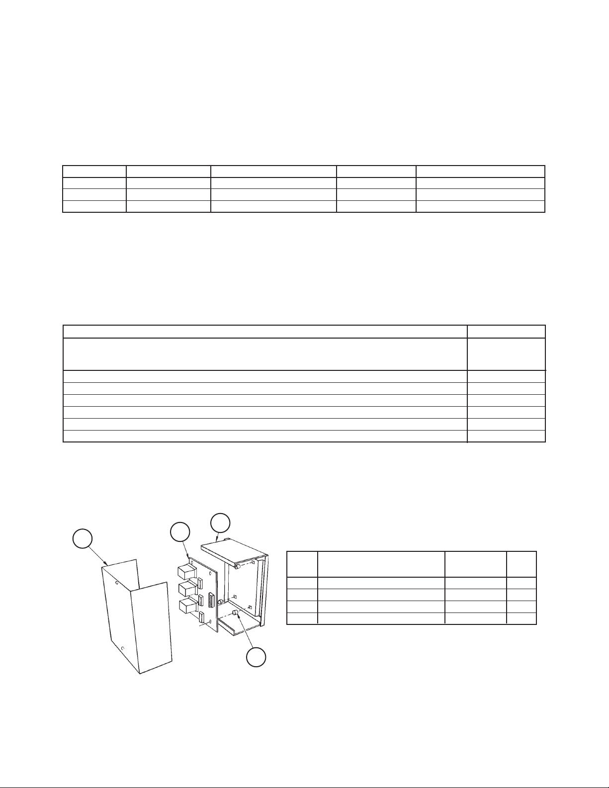
056794201
Multiple Unit Control Panel Kit
310
2 Tier 2- Stage WSHP; WGTH, WGTV 026- 072 Design 1 New 8/12 RPL 700025100 / Page 19
311
313
Ref. Description Part No. Qty.
No.
310 Cover, Control Box 106436101 1
311 Circuit Board 056794001 1
312 Stand Off, Circuit Board 802028090 6
313 Box 850007827 1
312
Page 20

Critical Daikin McQuay OEM Parts Are What Your
Daikin McQuay HVAC Unit Needs!
SmartSourceTM 2-Stage WSHP
WGTH, WGTV
Sizes 026 - 072
Design 1
CRITICAL PART
COMPONENTS MODEL UNIT SIZE VOLTAGE NUMBER
CONTROLS
MicroTech III Control Board, Series 2 ALL ALL N/A 250806500
I/O Expansion Board Assy, Series 2 ALL ALL N/A 250806601
LonWorks Comm. Card & Software ALL ALL N/A 250806801
BACnet Comm. Card & Software ALL ALL N/A 250806701
COMPRESSOR
20200 BTUH ALL 026 208-230/60/1 910115767
26400 BTUH ALL 032 208-230/60/1 910115770
30600 BTUH ALL 038 208-230/60/1 910115773
36900 BTUH ALL 044 208-230/60/1 910115776
41100 BTUH ALL 049 208-230/60/1 910115779
51900 BTUH ALL 064 208-230/60/1 910115785
60800 BTUH ALL 072 208-230/60/1 910115788
20100 BTUH ALL 026 265/60/1 910115768
26100 BTUH ALL 032 265/60/1 910115400
20000 BTUH ALL 026 460/60/3 910115769
26100 BTUH ALL 032 460/60/3 910115771
30600 BTUH ALL 038 460/60/3 910115774
36800 BTUH ALL 044 460/60/3 910115777
41200 BTUH ALL 049 460/60/3 910115780
52100 BTUH ALL 064 460/60/3 910115786
60900 BTUH ALL 072 460/60/3 669816421
20100 BTUH ALL 026 208-230/60/3 910115787
26100 BTUH ALL 032 208-230/60/3 910115772
30600 BTUH ALL 038 208-230/60/3 910115775
36900 BTUH ALL 044 208-230/60/3 910115778
41100 BTUH ALL 049 208-230/60/3 910115781
52100 BTUH ALL 064 208-230/60/3 910115787
61000 BTUH ALL 072 208-230/60/3 669816422
BLOWER FAN MOTOR
1/3HP ALL 026 208-230/60/1 669822525
1/2HP ALL 032 208-230/60/1 669822527
1/2HP ALL 038 208-230/60/1 669822529
3/4HP ALL 044 208-230/60/1 669822531
3/4HP ALL 049 208-230/60/1 669822533
1HP ALL 064 208-230/60/1 669822535
1HP ALL 072 208-230/60/1 669822537
1/3HP ALL 026 265/60/1 669822526
1/2HP ALL 032 265/60/1 669822528
1/2HP ALL 038 265/60/1 669822530
3/4HP ALL 044 265/60/1 669822532
3/4HP ALL 049 265/60/1 669822534
1HP ALL 064 265/60/1 669822536
1HP ALL 072 265/60/1 669822538
Continued on next page.
Call Your Local Daikin McQuay Parts Distributor For All Your Parts Needs.
To Locate A Distributor, Go To www.DaikinMcQuay.com or Call 1-800-37PARTS
7000251 New 8/2012 CPL Page 1 of 2
Page 21

Critical Daikin McQuay OEM Parts Are What Your
Daikin McQuay HVAC Unit Needs!
SmartSourceTM 2-Stage WSHP
WGTH, WGTV
Sizes 026 - 072
Design 1
CRITICAL PART
COMPONENTS MODEL UNIT SIZE VOLTAGE NUMBER
BLOWER FAN ASSY
Blower Housing & Wheel Assy ALL 026, 032 ALL 667838701
Blower Housing & Wheel Assy ALL 038-072 ALL 668151101
REFRIGERATION CIRCUIT
Reversing Valve ALL 026, 032 N/A 910125412
Reversing Valve ALL 038 N/A 910118735
Reversing Valve ALL 044-072 N/A 910125410
Solenoid-Reversing Valve ALL ALL N/A 106694207
Thermal Expansion Valve 1.5 Ton ALL 026 N/A 910115789
Thermal Expansion Valve 2 Ton ALL 032, 038 N/A 910116444
Thermal Expansion Valve 2.5 Ton ALL 044 N/A 910116445
Thermal Expansion Valve 3 Ton ALL 049, 064 N/A 910116446
Thermal Expansion Valve 4 Ton ALL 072 N/A 910116447
SENSOR
Discharge Air Sensor (DAT) 10K/72" ALL ALL N/A 910106325
Return Air Sensor (RAT) 10K/72" ALL ALL N/A 910106325
Entering Water Sensor (EWT) 10K/80" ALL 026, 032 N/A 910121231
Leaving Water Sensor (LWT) 10K/80" ALL 026, 032 N/A 910121231
Entering Water Sensor (EWT) 10K/80" ALL ALL N/A 107201601
Leaving Water Sensor (LWT) 10K/80" ALL ALL N/A 107201601
Call Your Local Daikin McQuay Parts Distributor For All Your Parts Needs.
To Locate A Distributor, Go To www.DaikinMcQuay.com or Call 1-800-37PARTS
7000251 New 8/2012 CPL Page 2 of 2
 Loading...