

Page 1
Installation Operation & Maintenance Data
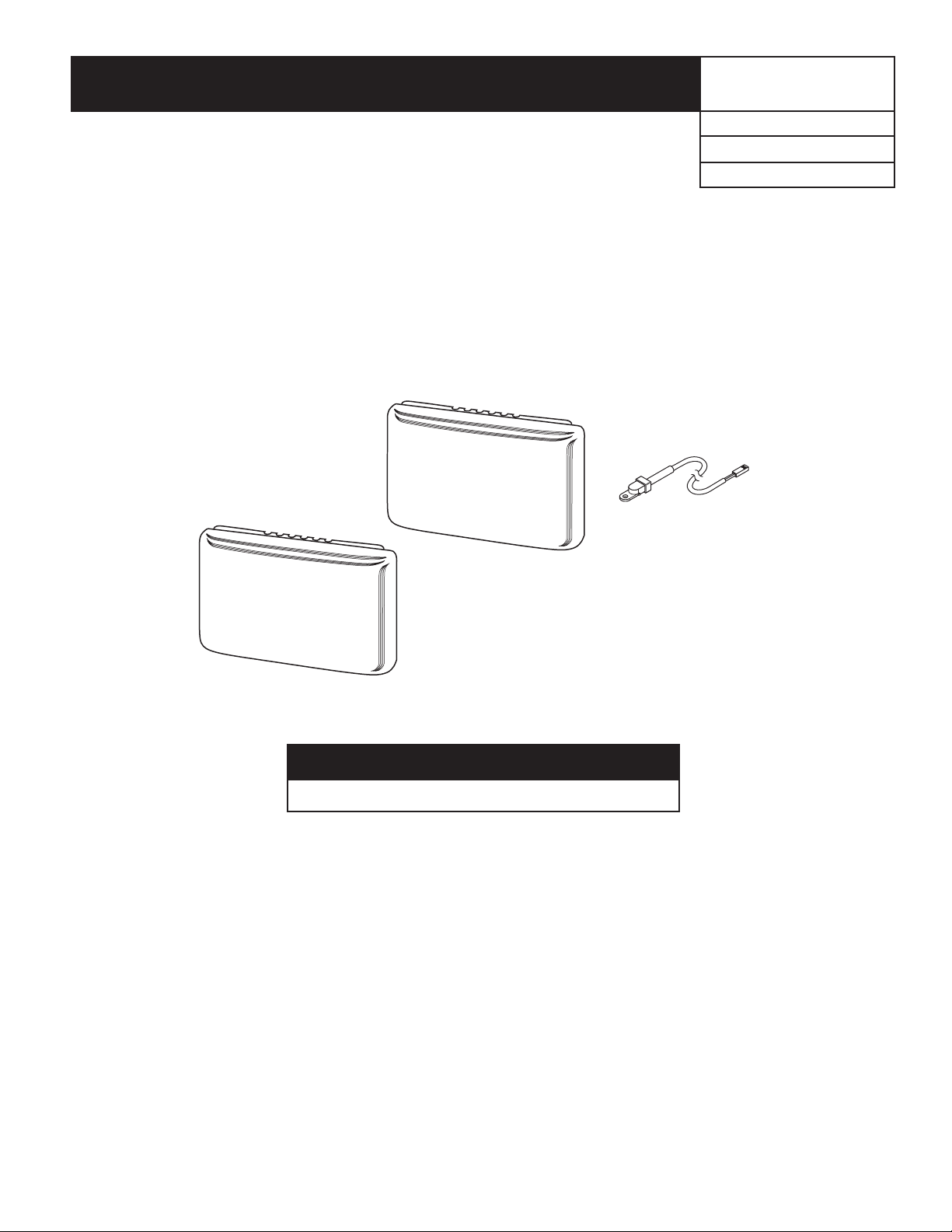
Remote Sensors
Indoor (Part No. 910129095)
Outdoor (Part No. 910129096)
Used With:
Programmable Touch-Screen Thermostat (Part No. 910121750)
SmartSource™ Units - Models GS & GT
Outdoor Probe
IOM 1175
Group: WSHP
Part Number: 910133390
Date: July 2012
Outdoor Remote Sensor
Indoor Remote Sensor
IMPORTANT!
Operator, save these instructions for future use!
Contents
Safety ....................................................................................2
Specications
Installation
Indoor Sensor
Outdoor Sensor
......................................................................2
............................................................................2
...................................................................2
................................................................2
Wiring
...................................................................................3
Indoor Remote Sensor Wiring Diagram
Outdoor Remote Sensor Wiring Diagram
Conguration
Troubleshooting Chart
.......................................................................4
......................................................4
............................3
.........................3
©2012 McQuay International • 800.432.1342 • www.mcquay.com
Page 2

Safety
WARNING
Wiring connections must be made in accordance with all
applicable electrical codes. Failure to read and follow all instructions carefully before installing or operating this control could
cause personal injury and/or property damage.
CAUTION
To prevent electrical shock, disconnect electric power to system
at main fuse or circuit breaker box until installation is complete.
If in doubt about whether your wiring is millivolt, line, or low volt-
age, have it inspected by a qualied heating and air conditioning
contractor or electrician.
Do not exceed the specication ratings.
All wiring must conform to local and national electrical codes
and ordinances.
This control is a precision instrument, and should be handled
carefully. Rough handling or distorting components could cause
the control to malfunction.
The remote sensors cannot be used with systems where power
interruptions are part of normal system operation.
NOTICE
Specications
Note: Remote sensor 910129095 is approved for indoor use
only.
Temperature range: 40° to 99°F
Operating humidity range: 0 to 90% RH (non-condensing).
20-gauge, three-conductor shielded cable must be used for all
remote sensor wiring.
Note: Remote sensor 910129096 is approved for outdoor
use only.
Temperature range of outdoor probe: -40° to 140°F
20-gauge, three-conductor shielded cable must be used for all
remote sensor wiring.
Installation
Indoor Sensor
5. Avoid locations close to windows, adjoining outside
walls, or doors that lead outside.
6. Avoid locations close to air registers or in the direct path
of air from them.
7. Make sure there are no pipes or duct work in that part of
the wall chosen for the sensor location.
8. Never locate sensor in a room that is normally warmer or
cooler than the other areas being conditioned.
9. Avoid locations with poor air circulation, such as behind
doors or in alcoves.
10. In the home, the living or dining room is normally a
good location, provided there is no cooking range or
refrigerator on opposite side of wall.
Outdoor Sensor
Select Sensor Location
Proper location insures that the remote sensor will provide a
correct outdoor temperature reading. Observe the following
general rules when selecting a location:
1. The interior mounting base can be located a maximum of
300 feet from the thermostat.
2. Install the interior mounting base within 12 ft. of the
intended outdoor probe location.
3. Never install the outdoor probe where it will be exposed
to direct light from lamps, sun, replaces or any
temperature radiating equipment.
4. Make sure there are no pipes or ductwork in the wall
chosen for the base location.
5. Outdoor temperature measurement requires installing the
probe outdoors. Good probe locations would be under a
bay window or overhang, out of direct sunlight. Direct
sun exposure will affect sensed temperature. Install probe
with spacer to obtain a more accurate temperature.
Figure 1: Outdoor probe mounting detail
Spacer
Mounting
Surface
Select Sensor Location
Proper location insures that the remote sensor will provide a
comfortable home or building temperature. Observe the following general rules when selecting a location:
1. The remote sensor can be located a maximum of 300 feet
from the thermostat.
2. Locate sensor about 5 ft. above the room oor level.
3. Install sensor on a partitioning wall, not on an outside wall.
4. Never expose sensor to direct light from lamps, sun,
replaces or any temperature radiating equipment.
Page 2 of 4 / IOM 1175
6. Although connected to the probe wire for outdoor
temperature sensing, the interior mounting base must be
placed indoors. Therefore, the interior mounting base
must be installed near the perimeter of the building, so
that the probe wire can be run through to the outside of
the structure and placed in the selected (shaded) location.
The outdoor probe wire is 12 feet long (and should
not be cut or spliced), so plan the placement of both
the probe and interior mounting base accordingly. Any
excess wire may be coiled or bundled. The probe should
be connected to E2 as shown in Figure 3.
Page 3

Wiring
CAUTION
Do not allow the 3-conductor wire to be pinched between the
sensor and the wall.
Check wire connections before applying power. Improper con-
nections will lead to permanent damage to the sensor.
20-Gauge Shielded cable must be used. Cable shield must be
connected to “-” or S3 on the THERMOSTAT ONLY.
Old Terminal (Thermostat or
Remote)
S1 +
S2 S
S3 -
New Terminal
(Thermostat or Remote)
Table 8: Indoor sensor
Table 7: Connection cross-reference
Model Number Color Dimensions Application
910129095 Classic White 2-1/8" × 3-1/2" × 3/4"
Compatible with Programmable Touch Screen Thermostat (Part No. 910121750)
with indoor remote sense
Table 9: Outdoor sensor
Model Number Color Dimensions Application
910129096 Classic White 2-1/8" × 3-1/2" × 3/4" with 12' sensor lead
Compatible with Programmable Touch Screen Thermostat (Part No. 910121750)
with outdoor remote sense
Indoor Remote Sensor Wiring Diagram
Figure 2: Indoor Remote Sensor (910129095) wiring to Programmable Touch Screen Thermostat (910121750)
Thermostat Base
Remote Indoor Sensor
+
S
W1
L
Y2
Y
G
RC
RH
C
+
S
-
D/A
W4
W3
6
W2
E2
–
Outdoor Remote Sensor Wiring Diagram
Figure 3: Outdoor Remote Sensor (910129096) wiring to Programmable Touch Screen Thermostat (910121750)
Thermostat Base
W1
L
Y2
Y
G
RC
RH
C
Outdoor Probe
+
S
-
D/A
W4
W3
6
W2
Remote Outdoor Sensor
+
S
E2
–
IOM 1175 / Page 3 of 4
Page 4

Conguration
When installing a remote sensor you must enable the remote sensor option. See “Installer/Conguration Menu” in IM 1178.
Troubleshooting Chart
To function correctly and read temperature accurately, the thermostat (when set up for a remote as outlined above) must have
constant 24-volt power. If the thermostat temperature is steadily dropping, reading low, or reads 08° when a remote sensor is
installed, it can be traced to one of the three following conditions.
Condition Test Comments
On models with batteries, remove the batteries and re-
1. Loss of 24-volt power.
2. A broken wire on +, SA, - from
the thermostat to the remote.
3. A shorted or damaged remote
sensor.
install thermostat. If the display is blank, check heating and
cooling system to determine why 24-volt power is absent.
Disconnect sensor wires at thermostat. Attach a short piece
(2') of three-wire shielded cable to (+, SA -) on the subbase.
Bring the remote sensor to the thermostat, location and
attach (+, S, -) respectively. Reattach thermostat. If the
temperature begins to climb (slowly), it is reading correctly.
If it reads correctly with the 2' length but improperly when
attached to the wire run, it indicates a fault in the wire run.
Because it is an electronic sensor, there are no Ohm values
to test. If correct conditions as listed in 1 & 2 above and the
temperature stays at or near 08°, it indicates a shorted or
damaged remote sensor.
Note: Digital thermostats and remote sensors acclimate very slowly to temperature change. It may take an hour or more for the
temperature to acclimate to the room temperature from a low temperature reading as outlined above. To expedite the room
temperature display use the reset instructions listed in the installation instructions for the thermostat model you are working
with. When reset, the thermostat will default to a room temperature of 70° and begin sensing room temperature. Be sure to
recongure the installer menu for a remote sensor because the reset function may cancel remote sensing.
For the sensor to read correctly, the 24-volt system power must
be present. Some systems may require an isolation relay to
provide constant power to the thermostat. Limit or safety
devices in the equipment can also cause a power interruption
Repair or replace the 3 wire shielded cable. Be sure the remote
wire run is not parallel to line voltage wires that carry heavy inductive loads, or across uorescent light ballasts that may cause
an inductance to be transmitted to the thermostat.
Replace remote sensor.
©2012 McQuay International • 800.432.1342 • www.mcquay.com IOM 1175 / Page 4 of 4
 Loading...