

Operating Manual
Group: Chiller
Part Number: 331373701
Effective: November 2008
Supersedes: OM WGS-4
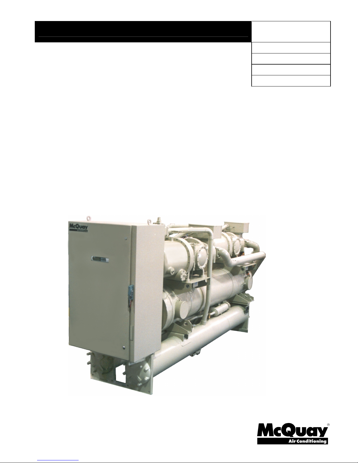
Water-Cooled Screw Compressor Chillers
WGS 130AW to WGS 190AW, Packaged Water-Cooled Chiller
WGS 130AA to WGS 190AA, Chiller with Remote Condenser
120 to 200 Tons, 420 to 700 kW
R-134a, 60 Hz
Software Version WGSD30101H
OM WGS-5
Table of Contents
Introduction ....................................... 3
General Description..................................... 3
Nomenclature............................................... 3
Definitions ..........................................4
W
iring Diagrams ............................... 8
Control Panel Layout...................... 10
MicroTech II Controller .............. 13
System Architecture................................... 13
General Description................................... 14
Units of measure........................................ 14
Sequence of Operation ....................16
Start-Up and Shutdown ..................23
Pre Start-up................................................ 23
Start-up ...................................................... 23
Weekend or Temporary Shutdown ............ 24
Start-up after Temporary Shutdown .......... 24
Extended Shutdown................................... 24
Start-up after Extended Shutdown............. 25
Unit Controller.................................28
Unit Inputs/Outputs ................................... 28
Unit Setpoints ............................................ 28
Circuit Controller............................ 31
Circuit Inputs and Outputs......................... 31
Circuit Setpoint Table................................ 32
Alarms and Events ..........................34
Unit Stop Alarms ....................................... 34
Unit Events ................................................ 36
Circuit Stop Alarms ................................... 36
Circuit Events ............................................ 38
Alarm Logging .......................................... 39
Event Logging ........................................... 40
Clearing Alarms......................................... 40
Unit Controller Functions............... 40
Unit Enable ................................................ 41
Unit Mode Selection .................................. 42
Unit States.................................................. 43
Evaporator Pump Control .......................... 44
Leaving Water Temperature (LWT) Reset . 45
Planned Unit Capacity Overrides .............. 47
Condenser Pump and Tower Control......... 48
Cooling Tower Control ..............................49
Evaporative Condenser Control................. 51
Circuit Controller Functions.......... 54
Refrigerant Calculations ............................54
Compressor Control................................... 55
Internal Capacity Overrides ....................... 58
Slide Positioning........................................ 59
Expansion Valve Control ...........................61
Oil Heater Control .....................................65
Starter Communications.............................65
Condenser Fan Control .............................. 66
Condenser Fan VFD ..................................68
Digital Output Control............................... 68
Using the Controller .................................. 69
Security...................................................... 71
Entering Passwords.................................... 71
Editing Setpoints........................................ 71
Clearing Alarms ......................................... 71
Menu Descriptions .......................... 72
Unit Controller........................................... 72
Circuit Controller....................................... 87
Editing Review ..........................................93
BAS Interface .................................. 94
Unit Troubleshooting Chart........... 95
Conform to the BACnet protocol
(ANSI/ASHRAE 135-2001).
Illustrations and data cover McQuay International products at the time of publication and we reserve the right to make
The following are trademarks or registered trademarks of their respective companies:
BACnet from ASHRAE; L
2 WGS 130A to WGS 190A OM WGS-5
2008 McQuay International
changes in design and construction at anytime without notice.
ONMARK and LONWORKS from Echelon Corporation;
GeneSys, McQuay and MicroTech II from McQuay International.
Unit controllers are LONMARK
certified with an optional L
communications module.
ONWORKS

Introduction
General Description
McQuay Model WGS water chillers are designed for indoor installations and are available
with factory-mounted water-cooled condensers (Model WGS AW), or arranged for use with
remote air-cooled or evaporative condensers (Model WGS AA). Each water-cooled unit
(WGS-AW) is completely assembled and factory wired before factory evacuation, charging
and testing. The units consist of two semi-hermetic rotary screw compressors, a two-circuit
shell-and-tube evaporator, two shell-and-tube water-cooled condensers, and complete
refrigerant piping.
Units manufactured for use with remote condensers (Models WGS-AA) have all refrigerant
specialties factory-mounted and have two sets of connection points for refrigerant discharge
and liquid lines to and from the remote condenser. Discharge valves are included
Each circuit’s liquid line components are manual liquid line shutoff valve, charging valve,
filter-drier, liquid line solenoid valve, sight glass/moisture indicator, and electronic
expansion valve.
The electrical control center includes a MicroTech II microprocessor control system and
equipment protection and operating controls necessary for dependable, automatic operation.
The compressor circuits are equipped with individual circuit breakers and a unit disconnect
switch is available as an option over the standard power block.
This software revision adds fixes several bugs in the IP/SI units logic, improves the
operation of remote evaporator units in low ambient air temperatures, improves
communications with the solid state starter and provides compressor electrical data at the
supervisor port for building automation systems.
Nomenclature
W G S 130 - A W
Water-Cooled Condensing
Rotary Screw Compressor
Nominal Capacity (Tons)
Global
W = Water-Cooled Condenser
A = Unit Less Condenser
Design Vintage
OM WGS-5 WGS 130A to 190A 3

Definitions
Active Setpoint
The active setpoint is the setting in effect at any given moment. This variation occurs on
setpoints that can be altered during normal operation. Resetting the chilled water leaving
temperature setpoint by one of several methods, such as return water temperature, is an
example.
Active Capacity Limit
The active setpoint is the setting in effect at any given moment. Any one of several external
inputs can limit a compressor’s capacity below its maximum value.
Condenser Recirc Timer
A timing function, with a 30-second default, that holds off any reading of condenser water
for the duration of the timing setting. This delay allows the water sensors (especially water
temperatures) to take a more accurate reading of the condenser water system conditions.
Condenser Saturated Temperature Target
The saturated condenser temperature target is calculated by first using the following
equation:
Sat condenser temp target raw = 0.833(evaporator sat temp) + 68.34
The “raw” value is the initial calculated value. This value is then limited to a range defined
by the Condenser Saturated Temperature Target minimum and maximum setpoints. These
setpoints simply cut off the value to a working range, and this range can be limited to a
single value if the two setpoints are set to the same value.
CPU Error
These are problems caused by a malfunction of the central processing unit.
Dead Band
The dead band is a set of values associated with a setpoint such that a change in the variable
occurring within the dead band causes no action from the controller. For example, if a
temperature setpoint is 44F and it has a dead band of 2 degrees, nothing will happen until
the measured temperature is less than 42F or more than 46F.
DIN
Digital input, usually followed by a number designating the number of the input.
Discharge Superheat
Discharge superheat shall be calculated for each circuit using the following equation:
Discharge Superheat = Discharge Temperature – Condenser Saturated Temperature
Error
In the context of this manual, “Error” is the difference between the actual value of a variable
and the target setting or setpoint.
Evaporator Approach
The evaporator approach is calculated for each circuit. The equation is as follows:
Evaporator Approach = LWT – Evaporator Saturated Temperature
4 WGS 130A to 190A OM WGS-5

Evap Recirc Timer
A timing function, with a 30-second default, that holds off any reading of chilled water for
the duration of the timing setting. This delay allows the chilled water sensors (especially
water temperatures) to take a more accurate reading of the chilled water system conditions.
EXV
Electronic expansion valve, used to control the flow of refrigerant to the evaporator,
controlled by the circuit microprocessor.
High Saturated Condenser – Hold Value
High Cond Hold Value = Max Saturated Condenser Value – 5F
This function prevents the compressor from loading whenever the pressures approach
within 5 degrees of the maximum discharge pressure. The purpose is to keep the
compressor online during periods of possibly temporary elevated pressures.
High Saturated Condenser – Unload Value
High Cond Unload Value = Max Saturated Condenser Value – 3F
This function unloads the compressor whenever the pressures approach within 3 degrees of
the maximum discharge pressure. The purpose is to keep the compressor online during
periods of possibly temporary elevated pressures.
High Superheat Error
The degrees of temperature difference between 40F and the actual discharge temperature.
Light load Stg Dn Point
The percent load point at which one of two operating compressors will shut off, transferring
the unit load to the remaining compressor.
Load Limit
An external signal from the keypad, the BAS or a 4-20 ma signal that limits the compressor
loading to a designated percent of full load. Frequently used to limit unit power input.
Load Balance
Load balance is a technique that equally distributes the total unit load among the running
compressors.
Low Ambient Lockout
Prevents the unit from operating (or starting) at ambient temperatures below the setpoint.
Low Pressure Hold Setpoint
The psi evaporator pressure setting at which the controller will not allow further compressor
loading.
Low/High Superheat Error
The difference between actual evaporator superheat and the superheat target.
LWT
Leaving water temperature. The “water” is any fluid used in the chiller circuit.
OM WGS-5 WGS 130A to 190A 5

LWT Error
Error in the controller context is the difference between the value of a variable and the
setpoint. For example, if the LWT setpoint is 44F and the actual temperature of the water
at a given moment is 46F, the LWT error is +2 degrees.
LWT Slope
The LWT slope is an indication of the trend of the water temperature. It is calculated by
taking readings of the temperature every few seconds and subtracting them from the
previous value, over a rolling one-minute interval.
ms
Milli-second
Maximum Saturated Condenser Temperature
The maximum saturated condenser temperature allowed is calculated based on the
compressor operational envelope.
NC
Normally closed - usually refers to a contactor or valve.
NO
Normally open - usually refers to a contactor. or valve.
OAT
Outside ambient air temperature.
Offset
Offset is the difference between the actual value of a variable (such as temperature or
pressure) and the reading shown on the microprocessor as a result of the sensor signal. See
notes on page 33 for explanation of sensor off set.
pLAN
Peco Local Area Network is the proprietary name of the network connecting the control
elements.
Rapid Stop
A compressor stop process that circumvents the normal pumpdown cycle.
Refrigerant Saturated Temperature
Refrigerant saturated temperature is calculated from the pressure sensor readings for each
circuit. The pressure is fitted to an R-134a temperature/pressure curve to determine the
saturated temperature.
Soft Load
Soft Load is a control sub-routine that allows the chiller to load up gradually. It requires
setpoint inputs of selecting it by Yes or No inputs, by selecting the percent load to start
ramping up, and by selecting the time to ramp up to full load (up to 60 minutes).
SP
Setpoint
SSS
Solid state starter as used on McQuay screw compressors.
Suction Superheat
Suction superheat is calculated for each circuit using the following equation:
Suction Superheat = Suction Temperature – Evaporator Saturated Temperature
6 WGS 130A to 190A OM WGS-5

Stage Up/Down Accumulator
The accumulator can be thought of as a bank storing occurrences that indicate the need for
an additional fan.
Stageup/Stagedown Delta-T
Staging is the act of starting or stopping a compressor or fan when another is still operating.
Startup and Stop is the act of starting the first compressor or fan and stopping the last
compressor or fan. The Delta-T is the “dead band” on either side the setpoint in which no
action is taken.
Stage Up Delay
The time delay from the start of the first compressor to the start of the second.
Startup Delta-T
Number of degrees above the LWT setpoint required to start the first compressor.
Stop Delta-T
Number of degrees below the LWT setpoint required for the last compressor to stop.
VAC
Volts, Alternating current, sometimes noted as vac.
VDC
Volts, Direct current, sometimes noted as vdc.
VFD
Variable Frequency Drive, a device used to vary an electric motor’s speed.
OM WGS-5 WGS 130A to 190A 7

Wiring Diagrams
UNIT MAIN
A
A
Figure 1, WGS 130AW – 190AW Field Wiring Diagram (Optional Single Point Connection)
3 PHASE
POWER
SUPPLY
DISCONNECT
(BY OTHERS)
TERMINAL BLOCK
GND LUG
TO COM PRESSO R(S)
NOTE: ALL FIELD WIRING TO BE
INSTALLED AS NEC CLASS 1
WIRING SYSTEM WITH CONDUCTOR
RATED 600 VOLTS
FACTORY SUPPLIED ALARM
FIELD WIRED
ALARM BELL
OPTION
ABR
LARM BELL RELAY
FUSED CONTROL
CIRCUIT TRANSFORMER
CHWR
EVAP. PUMP RELAY #1
(BY OTHERS)
120 VAC 1.0 AMP MAX
CHWR
EVAP. PUMP RELAY #2
(BY OTHERS)
120 VAC 1.0 AMP MAX
CWR
COND. PUMP RELAY #1
(BY OTHERS)
120 VAC 1.0 AMP MAX
CWR
COND. PUMP RELAY #2
(BY OTHERS)
120 VAC 1.0 AMP MAX
M11
TOWER FA N #1
(BY OTHERS)
120 VAC 1.0 AMP MAX
M12
TOWER FA N #2
(BY OTHERS)
120 VAC 1.0 AMP MAX
COOLING TOWER BYPASS
(BY OTHERS)
(BY OTHERS)
FU4 FU5
120 VAC
FU7
TB1
(115 VAC)
1
2
82
2
85
2
86
2
87
2
88
2
89
2
78
77
80
79
81
75
TB1-2
N
24 VAC
120 VAC
N
120 VAC
N
120 VAC
N
120 VAC
N
120 VAC
N
120 VAC
N
0-10VDC
N
0-10VDC
BELL
COM NO
12
ALARM BELL OPTION
LARM BELL
RELAY
REMOTE STOP
SWITCH
(BY OTHERS)
ICE MODE
SWITCH
(BY OTHERS)
EVAP. FLOW
SWITCH
(BY OTHERS)
*MANDATORY IF FACTORY FLOW SWITCH OPTION IS NOT SELECTED
COND. FLOW
SWITCH
(BY OTHERS)
*MANDATORY IF FACTORY FLOW SWITCH OPTION IS NOT SELECTED
EVAP. WATER RESET
8 WGS 130A to 190A OM WGS-5
TIME
CLOCK
AUTO
ON
AUTO
ON
NOR. OPEN PUMP AUX.
CONTACTS (OPTIONAL)
NOR. OPEN PUMP AUX.
CONTACTS (OPTIONAL)
4-20MA FOR
(BY OTHERS)
4-20MA FOR
DEMAND LIMIT
(BY OTHERS)
OFF
MANUAL
OFF
MANUAL
TB1
(24 VAC OR 30 VDC)
60
66
IF REMOTE STOP CONTROL
897
IS USED, REMOVE LEAD 897
FROM TERM. 40 TO 53.
60
68
60
67
60
76
+
-
+
-
72
70
71
70
DWG. 330588201 REV. 0B
GND
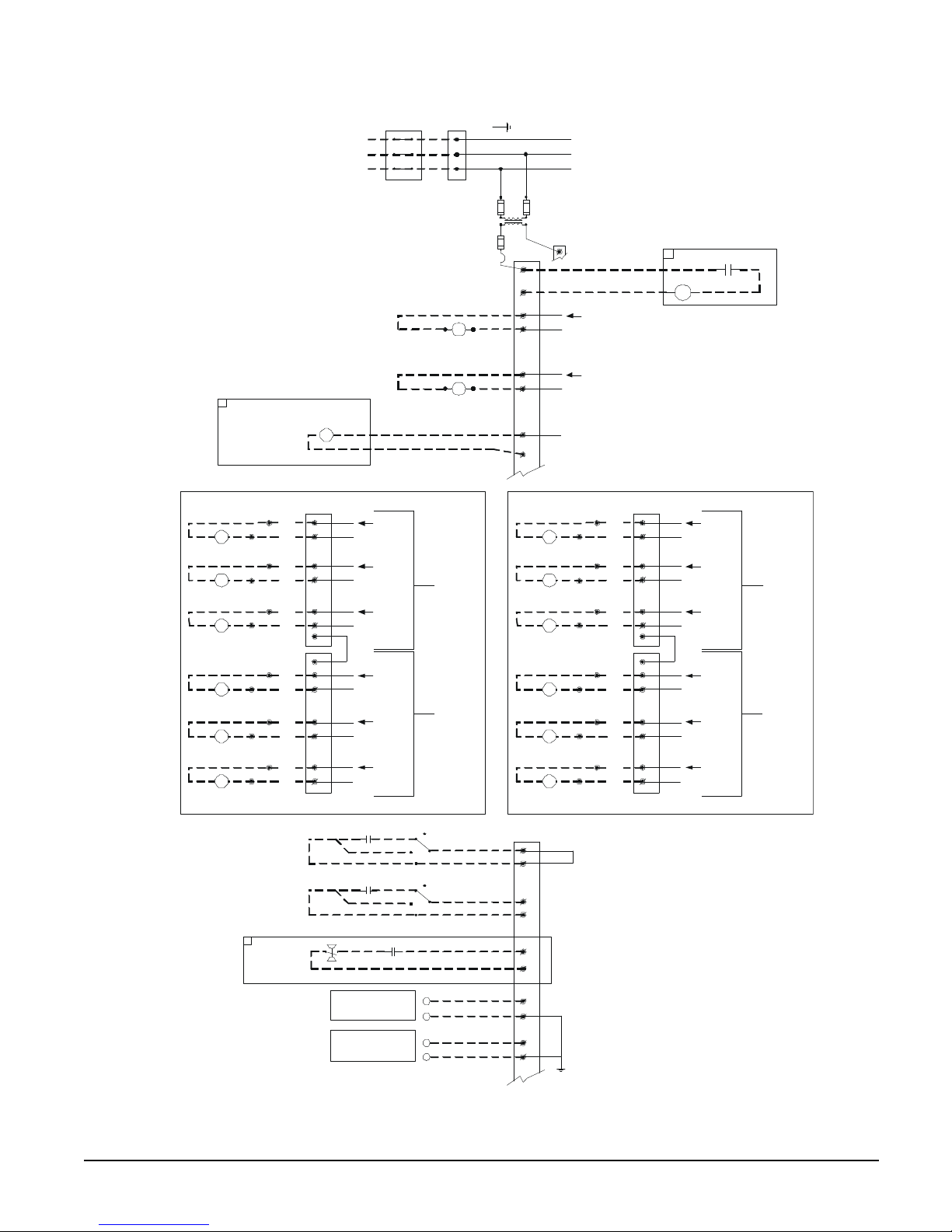
Figure 2, WGS 130AA – 190AA Field Wiring Diagram (Remote Air-cooled Condenser)
UNIT MAIN
(
)
)
3 PHASE
POWER
SUPPLY
DISCONNECT
(BY OTHERS)
TERMINAL BLOCK
GND LUG
TO COMPRESSOR(S)
NOTE: ALL FIELD WIRING TO BE
INSTALLED AS NEC CLASS 1
WIRING SYSTEM WITH CONDUCTOR
RATED 600 VOLTS
FACTORY SUPPLIED ALARM
ALARM BELL
OPTION
CIRCUIT #1
M11
CONDENSER FAN
CONTACTOR COIL #1
M12
CONDENSER FAN
CONTACTOR COIL #2
M13
CONDENSER FAN
CONTACTOR COIL #3
M14
CONDENSER FAN
CONTACTOR COIL #4
M15
CONDENSER FAN
CONTACTOR COIL #5
M16
CONDENSER FAN
CONTACTOR COIL #6
FIELD WIRED
TB6
92
144
98
145
93
146
98
145
94
148
98
145
95
150
98
145
96
152
98
145
97
154
98
145
REMOTE STOP
SWITCH
(BY OTHERS)
ICE MODE
SWITCH
(BY OTHERS)
ABR
ALARM BELL RELAY
NO1
2
NO2
2
NO3
2
C
C
NO4
2
NO5
2
NO6
2
FUSED CONTROL
CIRCUIT TRANSFORMER
EVAP. PUMP RELAY #1
120 VAC 1.0 AMP MAX
EVAP. PUMP RELAY #2
120 VAC 1.0 AMP MAX
120 VAC
N
120 VAC
N
120 VAC
N
(LOCATED ON
CONTROLLER)
120 VAC
N
120 VAC
N
(LOCATED ON
CONTROLLER)
120 VAC
N
TIME
CLOCK
AUTO
ON
MANUAL
AUTO
ON
MANUAL
OFF
OFF
CHWR
(BY OTHERS)
CHWR
(BY OTHERS)
J12
CIRCUIT
J13
CIRCUIT
FU4
120 VAC
FU7
TB1
(115 VAC)
CIRCUIT #2
CONDENSER FAN
CONTACTOR COIL #1
CONDENSER FAN
CONTACTOR COIL #2
CONDENSER FAN
CONTACTOR COIL #3
CONDENSER FAN
CONTACTOR COIL #4
CONDENSER FAN
CONTACTOR COIL #5
CONDENSER FAN
CONTACTOR COIL #6
TB1
24 VAC
FU5
TB1-2
1
2
82
2
85
2
81
120 VAC
N
120 VAC
N
24 VAC
ALARM BELL
BELL
COM
2
1
ALARM BELL OPTION
RELAY
NO
75
TB7
92
244
245
246
245
248
245
250
245
252
245
254
245
NO1
2
NO2
2
NO3
2
C
C
NO4
2
NO5
2
NO6
2
98
M21
93
98
M22
94
98
M23
95
98
M24
96
98
M25
97
98
M26
60
66
IF REMOTE STOP CONTROL
897
IS USED, REMOVE LEAD 897
FROM TERM. 40 TO 53.
N
N
N
N
N
N
120 VAC
120 VAC
120 VAC
120 VAC
120 VAC
120 VAC
J12
(LOCATED ON
CIRCUIT
CONTROLLER)
J13
(LOCATED ON
CIRCUIT
CONTROLLER
60
68
EVAP. FLOW
SWITCH
(BY OTHERS)
*MANDATORY IF FACTORY FLOW SWITCH OPTION IS NOT SELECTED.
OM WGS-5 WGS 130A to 190A 9
NOR. OPEN PUMP AUX.
CONTACTS (OPTIONAL)
4-20MA FOR
EVAP. WATER RESET
(BY OTHERS)
4-20MA FOR
DEMAND LIMIT
(BY OTHERS)
60
67
+
-
+
-
72
70
71
70
GND
DWG. 330588101 REV. 0C
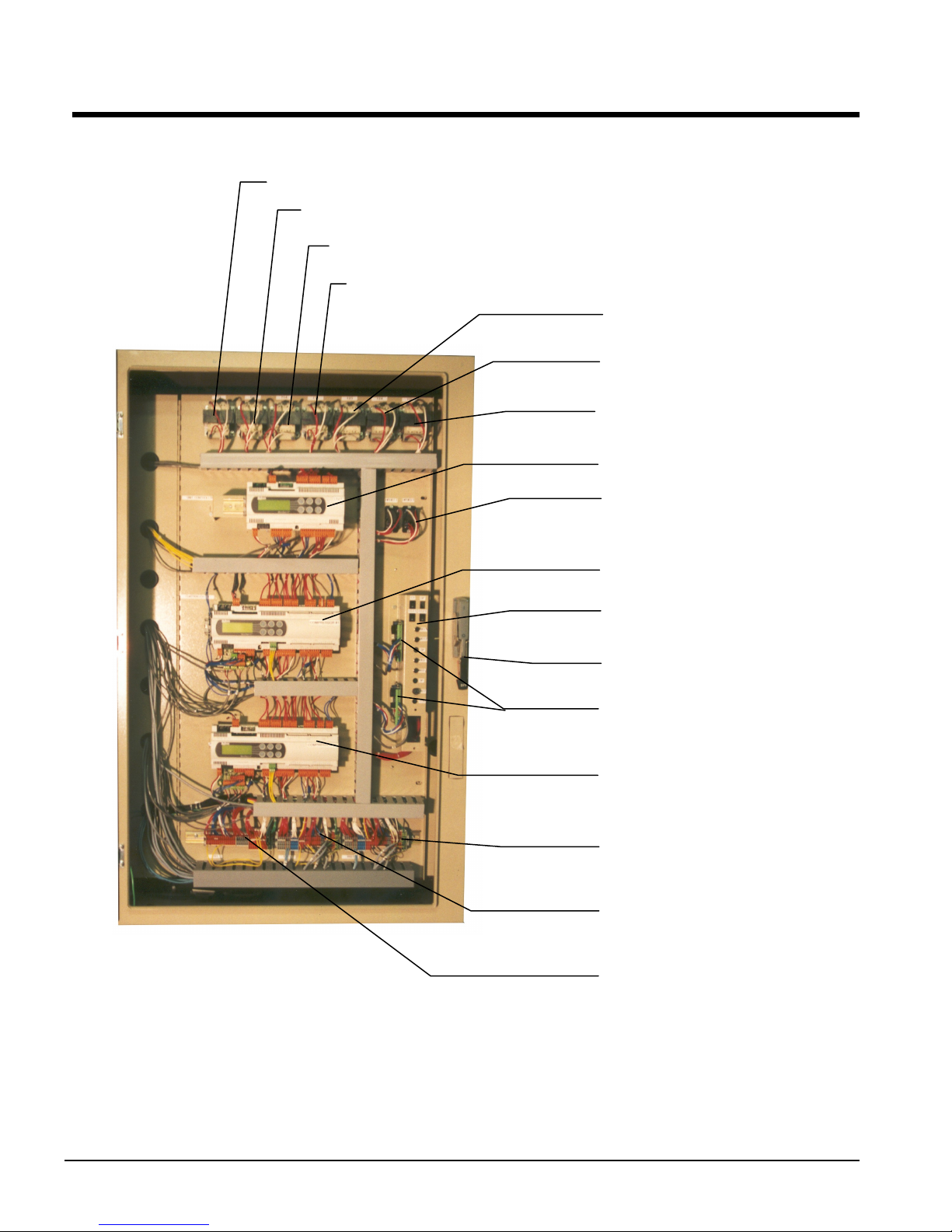
Control Panel Layout
r
r
Figure 3, Outer (Microprocessor) Panel
T2, Unit Controlle
T13, Circ#1 Controller
T14, Circ#1 Load Solenoid
T15, Circ#1 EXV Power
T23, Circ#2 Controlle
T24, Circ#2 Load Solenoid
T25, Circ#2 EXV Power
Unit Controller
MHPR11 &12, Mechanical
High Pressure Relay
Circ#1 Controller
Circuit Breaker &
Switch Panel
External Disconnect Handle
Circ#1 & 2 EXV Drivers
Circ#2 Controller
TB3, Circ#2 Controller
Terminal Board
TB2, Circ#1 Controller
Terminal Board
TB1 Unit Controller
Terminal Board
NOTES:
1. Transformers T2 through T25 are class 100, 120V to 12V.
2. Switches for MHPR 11 and 12 (Mechanical High Pressure Switches) are located on the compressors.
3. Mechanical High Pressure Switches Open at 310 psi, Close at 250 psi.
10 WGS 130A to 190A OM WGS-5

Figure 4, Inner (Power) Panel (Optional Single-Point Power with Disconnect Switches
Shown)
Circ#1 Solid State Starter
Circ#2 Solid State Starter
SSS1 Bypass Contactor
SSS2 Bypass Contactor
Secondary Fuses
External Disconnect Handle
Circ#1 Circuit Breaker
Circ#2 Circuit Breaker
Unit Disconnect Switch
W/ External Handle
T1, Supply Voltage to
120V Transformer
Primary Fuses
Outside (Microprocessor) Panel
OM WGS-5 WGS 130A to 190A 11
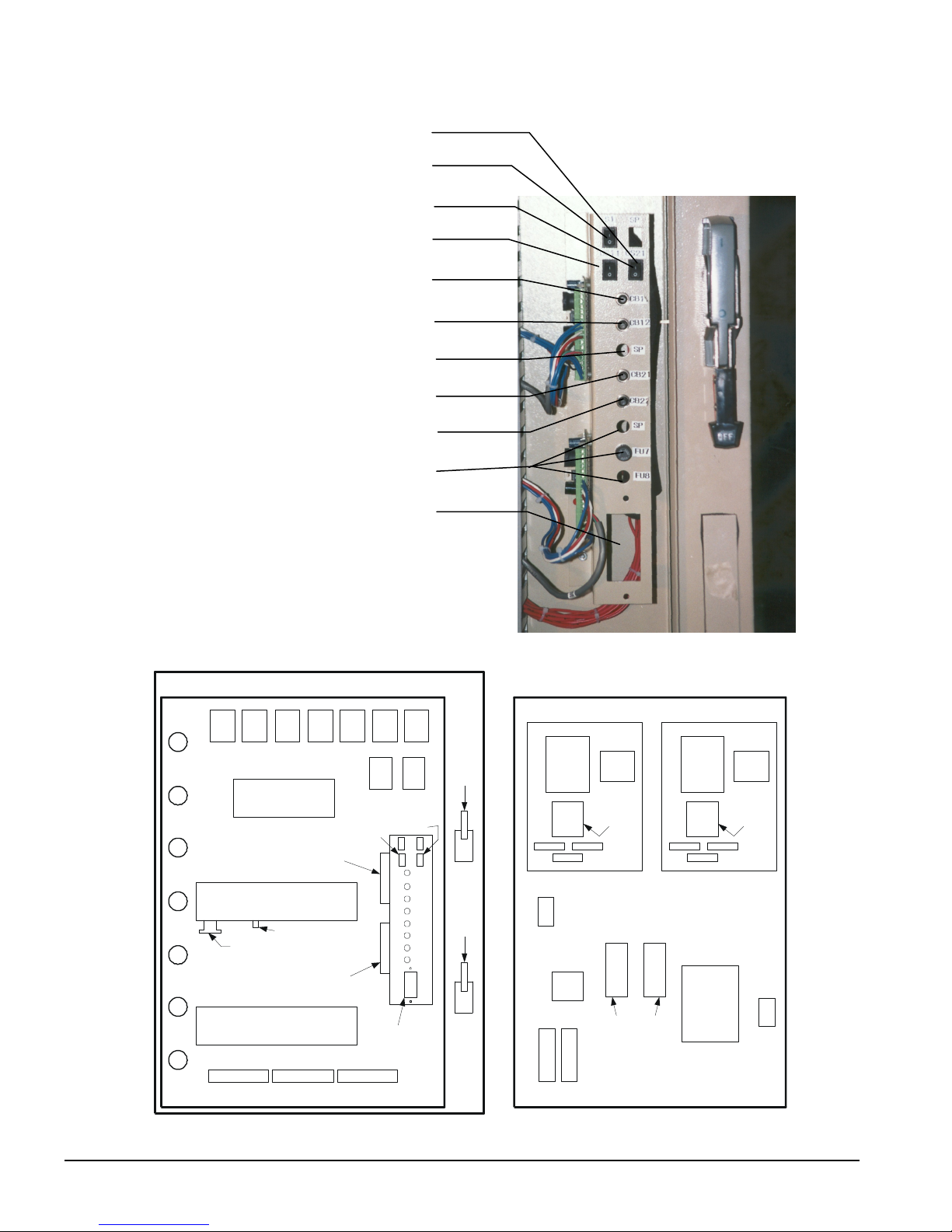
Figure 5, Circuit Breaker/Fuse Panel
Open Location
S1 Main Unit On-Off Switch
CS2, Circuit#2 On-Off Switch
CS1, Circuit#1 On-Off Switch
CB11 Circ#1 Circuit Breaker
CB12, Circ#1 Sump Heater
Open Location
CB21, Circ#2 Circuit
CB22, Circ#2 Sump Heater
Open Locations
Location for Optional
115V Receptacle
OUTER PANEL INNER PANEL
T13T2 T14 T15 T23 T24 T25
UNIT
CONTROLLER
EXV.
DRIVER
#1
CIRCUIT CONTROLLER
#1
MODBUS CARD
CONVERTER BOARD
EXV.
DRIVER
#2
CIRCUIT CONTROLLER
#2
TB1
TB11 TB21
MHPR1MHPR
CS1
S1S
REC
OPTION
2
CS2
CB11
CB12
SP
CB21
CB22
SP
FU7
F3
SINGLE
POINT
OR
CIR. #1
DS
HANDLE
(MULTI-
POINT)
P
CIR. #2
DS
HANDLE
(MULTI-
POINT)
SSS #1 SSS #2
D3
CT2
T1
F
U
5
CONTACTOR
CT1
THERM-
ISTOR
CARD
BYPASS
C
B
1
(DS1 DS2
MULTIPOINT
POWER)
CT3
C
B
2
CONTR.
BRD.
CT3
F
U
6
F
U
4
D3
CONTR.
BRD.
CT2
DS1
CONTACTOR
CT1
THERM-
ISTOR
CARD
BYPASS
G
N
D
12 WGS 130A to 190A OM WGS-5
330589001 REV. 00 - Legend

MicroTech II Controller
Software Version:WGSD30101E
Bios: 3.62
BOOT: 3.0F
System Architecture
The WGS MicroTech distributed control system consists of multiple microprocessorbased controllers that provide monitoring and control functions required for the controlled,
efficient operation of the chiller. The system consists of the following components:
Unit Controller
and communicates with the other controllers. It is located in the control panel and is
labeled “UNIT CONTROL”.
Circuit Controllers
settings specific to the circuit. The controllers are located in the control panel and are
labeled “CIRCUIT CONROL”.
In addition to providing all normal operating controls, the MicroTech II control system
monitors equipment protection devices on the unit and will take corrective action if the
chiller is operating outside of its normal design envelope. If an alarm condition develops,
the controller will shut down the compressor, or entire unit, and activate an alarm output.
Important operating conditions at the time an alarm condition occurs are retained in the
controller’s memory to aid in troubleshooting and fault analysis.
The system is protected by a password scheme that allows access only by authorized
personnel. The operator must enter the operator password into the controller’s keypad
before any setpoints can be altered.
, one per chiller controls functions and settings that apply to the unit
for each compressor/circuit that control compressor functions and
BAS Interface-
Modbus,
BACnet,
Lonworks
PLAN Addressing
Chiller
RS485/
LON
Unit Controller
4x20 LCD
Carel pLAN
Circuit Controller
Solid
State
Starter
RS485 RS485
Circuit Controller
4x20 LCD
4x20 LCD
Solid
State
Starter
The pLAN (proprietary local area network) addressing is based on a commonly used
scheme among all applications using pLAN networked MicroTech II controllers. Only
three addresses are needed, and are designated as shown in the following table.
Controller Address Dip Sw 1 Position Dip Sw 2 Position Dip Sw 3 Position
Unit 5 Up Down Up
Circuit 1 1 Up Down Down
Circuit 2 2 Down Up Down
The Dip switches are located on the upper front of the controller above the screen.
OM WGS-5 WGS 130A to 190A 13
General Description
The MicroTech II controller’s design permits the chiller to run more efficiently, and it
simplifies troubleshooting if a system failure occurs. Every MicroTech II controller is
programmed and tested prior to shipment to assist in a trouble-free start-up. The MicroTech
II controller can be used to cycle fans on remote air-cooled condensers for head pressure
control when the setpoint Water Cooled=N is selected in one of the setpoint menu screens.
Water Cooled=Y sets the chiller for operation with the water-cooled condenser and activates
settings for cooling tower control. Remote evaporative condensers will have to have selfcontained, on-board, head pressure control systems.
Units of measure
Version “C”, as described in this manual, supports metric (SI) units of measure.
Inch-Pound SI
F to 0.1F C to 0.1C
psi to 0.1 psi KPa to 1.0 kPa
Distributed Control
The WGS units have three MicroTech II microprocessors, a Unit Controller plus a Circuit
Controller for each of the two circuits. The Circuit Controllers are independent such that
either one will operate its circuit if the other Circuit Controller is out of service.
Operator-friendly
The MicroTech II controller menu structure is separated into three distinct categories, which
provide the operator or service technician with a full description of the following:
1. Current unit status
2. Control parameters (setpoint settings and adjustment). Security protection prevents
unauthorized changing of the setpoints and control parameters.
3. Alarm notification and clearing
The MicroTech II controller continuously performs self-diagnostic checks, monitoring
system temperatures, pressures and protection devices, and will automatically shut down a
refrigerant circuit or the entire unit if a fault occurs. The cause of the shutdown and date
stamp are retained in memory and can be easily displayed in plain English for operator
review, which is an extremely useful feature for troubleshooting. In addition to displaying
alarm diagnostics, the MicroTech II controller also provides the operator with a warning of
pre-alarm limit conditions.
Staging
The two screw compressors are loaded and staged on and off as a function of leaving chilled
water temperature, number of starts and run-hours. See Sequence of Operation beginning
on page 16.
Equipment Protection
The unit is protected by alarms that shut it down and require manual reset, and also by limit
alarms that limit unit operation in response to some out-of-ordinary condition. Shutdown
alarms activate an alarm signal that can be wired to a remote device.
14 WGS 130A to 190A OM WGS-5
Unit Enable Selection
A
(4)
Enables unit operation from local keypad or digital input.
Unit Mode Selection
Selects standard cooling, ice, glycol, or test operation mode.
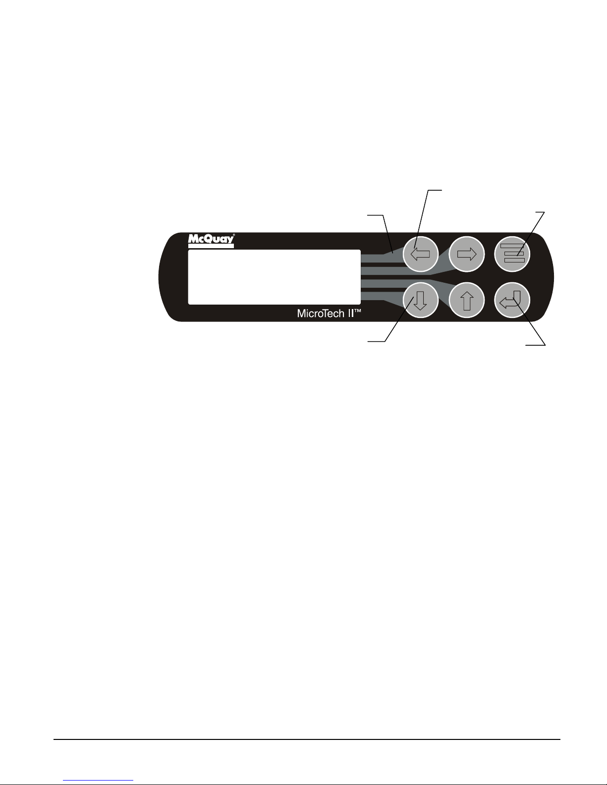
Keypad/Display
A 4-line by 20-character/line liquid crystal display and 6-key keypad is mounted on each
controller. Its layout is shown below.
Figure 6, Keypad and Display in MENU Mode
Air Conditioni ng
Key to Screen Pathway
<
LARM
<
VIEW
<
Arrow Keys
SET
"Enter" Key and Green
Red Alarm Light
Menu Key
Comp. Run Light
The four arrow keys (UP, DOWN, LEFT, RIGHT) have three modes of use.
1. Scroll between data screens as indicated by the arrows (default mode).
2. Select a specific data screen in a hierarchical fashion using dynamic labels on the right
side of the display (this mode is entered by pressing the MENU key).
3. Change field values in edit mode according to the following table:
LEFT Default
RIGHT Cancel
UP Increment
DOWN Decrement
These four edit functions are indicated by one-character abbreviations on the right side of
the display (this mode is entered by pressing the ENTER key).
OM WGS-5 WGS 130A to 190A 15

Sequence of Operation
Compressor Heaters
With the control power on, 120V power is applied through the control circuit Fuse FU7 to
the compressor oil separator heater (HTR-OIL SEP).
Startup/Compressor Staging
During Cool Mode the following must be true to start a circuit operating. The evaporator
and condenser pump (WGS-AW only) outputs must be energized and flow must be
established for a period of time defined by the evaporator recirculate setpoint. Established
flow will be detected by evaporator and condenser water flow switches. The water
temperature leaving the evaporator must be greater than the Active Leaving Water
Temperature setpoint, plus the Startup Delta-T, before a circuit will start. The first circuit to
start is determined by sequence number. The lowest sequence numbered circuit will start
first. If all sequence numbers are the same (default), then the circuit with the fewest number
of starts will start first.
During operation, the slide valves for loading and unloading will be pulsed until the active
leaving water temperature setpoint is maintained. The second circuit start will occur once
the first circuit has loaded to 75% slide capacity or is in Capacity Limit and the water
temperature leaving the evaporator is greater than the active leaving water temperature
Setpoint plus Stage Delta-T. The circuits will load or unload simultaneously through a
continuous capacity control to maintain the evaporator leaving water temperature. If all
sequence numbers are the same, the circuit with the most run hours will be shut down first.
The circuit with the most run hours will stop when the water temperature leaving the
evaporator is less than the Active Leaving Water Temperature Setpoint minus Stage DeltaT. The last remaining circuit will shut down when the water temperature leaving the
evaporator is lower than the Active Leaving Water Temperature Setpoint minus the Stop
Delta-T.
Automatic Pumpdown
The Model WGS chiller has two separate refrigerant circuits so the refrigerant charge is
stored in the condenser when the circuit is off. Pumpdown to the condenser helps keep
refrigerant from migrating to the compressor. It also helps establish a pressure differential
on start for oil flow. In a normal shutdown, each circuit will close its expansion valve,
causing the evaporator pressure to reach a low-pressure setpoint. Once this setpoint is
reached, or a specified amount of time has elapsed, the running circuit will be shut down.
Chilled Water and Condenser Water Pumps
The chiller’s MicroTech II controller has a total of four pump outputs, two for the
evaporator and two for the condenser (WGS-AW only). There is a manual setting in the
software for the user to select either pump output 1 or 2. It is recommended that the
chiller’s outputs control the water pumps, as this will offer the most protection for the unit.
Cooling Tower Control
The MicroTech II controller can control the cooling tower fans and/or a tower bypass valve.
This provides a simple and direct method to control the unit’s discharge pressure.
Programming directions and the sequence of operation can be found on page 49. Some
eans of discharge pressure control is recommended and must be installed if the entering
m
condenser water temperature to the condenser can fall below 60F.
Condenser Fan Control
The MicroTech II controller can be programmed to cycle air-cooled condenser fans on and
off based on the discharge pressure. Details are on page 66.
16 WGS 130A to 190A OM WGS-5

Low Ambient Start Logic
Low pressure operation at start (due to low ambient air temperature)is allowed for every
start regardless of the condenser saturated temperature at start or condenser configuration
( water-cooled or remote condenser). This is called Start Logic. START Logic is active for
a time period determined by the unit Startup Timer setpoint. This was called the Low OAT
Start Timer in previous software versions.
The Low OAT Restart Failure logic, which applies ONLY to units configured for remote
condenser, still allows for three start attempts. If the condenser saturated temperature at
start is less than 70F, another start attempt is allowed until failure of the third attempt,
which will generate an alarm.
Remote Condenser EXV Operation
For units configured for remote condensers, there is pre-open logic that allows the electronic
expansion valve to open prior to starting the compressor. This allows the expansion valve
to be in a better position for control at start-up. The factory mounted liquid line solenoid
remains closed until the compressor starts. On units configured for remote condensers, if
the evaporator pressure is greater than the condenser pressure at start, the pre-open logic is
bypassed. NOTE: Pre-open logic also exists for units configured as packaged water cooled
condensers.
Electronic expansion valve post-open logic has been added to help prevent hydraulic lock
between the liquid line solenoid and the electronic expansion valve when a circuit cycles
off. After the compressor performs a pump down and cycles off, the electronic expansion
valve will re-open for 30 seconds and then return to its closed position.
OM WGS-5 WGS 130A to 190A 17
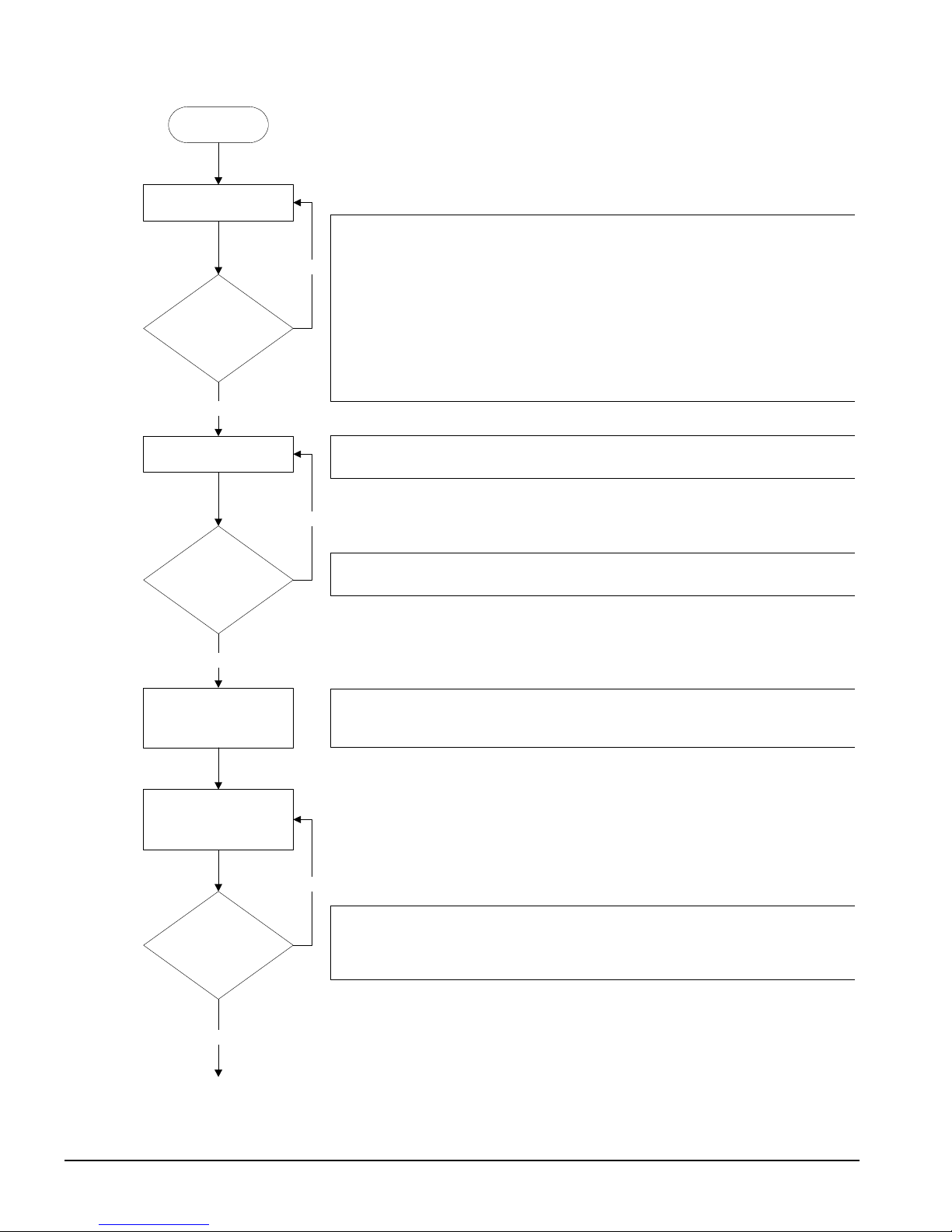
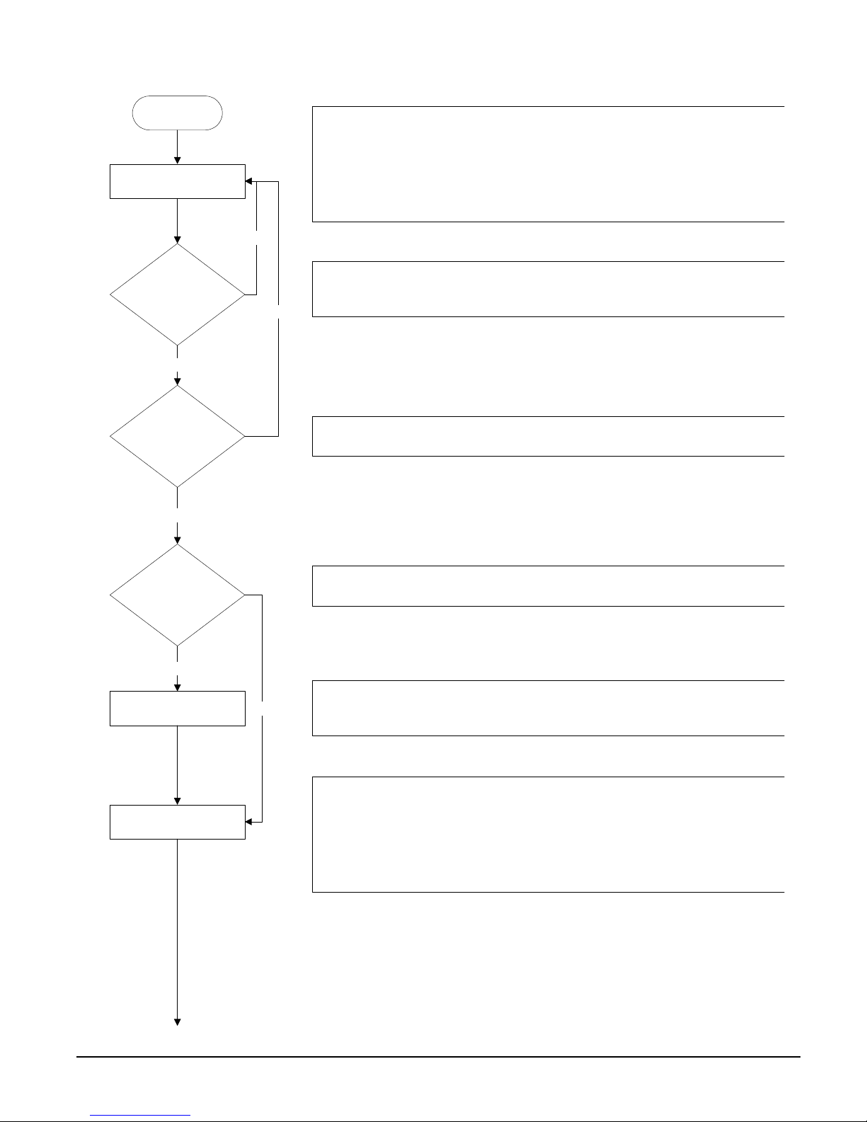
Unit Controller Sequence of Operation
Unit power up
Unit in Off state
The chiller may be disabled via the unit switch, the remote switch, the keypad
enable setting, or the BAS network. In addition, the chiller will be disabled if both
circuits are disabled, either because of an alarm or the circuit pumpdown switch on
No
each circuit, or if there is a unit alarm. If the chiller is disabled, the unit status
display will reflect this and also show why it is disabled.
Is unit enabled?
Yes
Evaporator pump output on
Is flow present?
Yes
Wait for chilled water loop to
recirculate.
If the unit switch is off, the unit status will be
disabled due to network command, the unit status will be
the remote switch is open, the unit status will be
alarm is active, the unit status will be
are enabled, the unit status will be
Off:All Cir Disabled
Off:Unit Switch
Off:Remote Switch
Off:Unit Alarm
. If the chiller is
Off:BAS Disable
. When a unit
. In cases where no circuits
.
If the chiller is enabled, then the unit will be in the Auto state and the evaporator
water pump output will be activated.
No
The chiller will then wait for the flow switch to close, during which time the unit
status will be
Auto:Wait for flow
.
After establishing flow, the chiller will wait some time to allow the chilled water loop
to recirculate for an accurate reading of the leaving water temperature. The unit
status during this time is
Auto:Evap Recirc
.
. When
Keep evaporator pump
output on while unit is
enabled.
No
Is there enough load to
start chiller?
Yes
18 WGS 130A to 190A OM WGS-5
The chiller is now ready to start if enough load is present. If the LWT is not high
enough to start, the unit status will be
If the LWT is high enough to start, the unit status will be
Auto:Wait Evap Flow
Auto
.
.

Is unit watercooled?
Yes
If the unit is configured as watercooled, the condenser pump will need to be started.
Otherwise, the unit can start the first circuit at this point.
Condenser pump output on
Is flow present?
Yes
Wait for condenser water
loop to recirculate.
Keep condenser pump
output on while unit is
enabled and load is present.
Start first circuit.
Load/unload as needed to
satisfy load.
Is more capacity
needed to satisfy load?
If load is present, the condenser water pump output will be activated.
No
The chiller will then wait for the condenser flow switch to close, during which time
the unit status will be
No
Auto:Wait Cond Flow
.
After establishing condenser flow, the chiller will wait some time to allow the
condenser water loop to recirculate and guarantee consistent flow. The unit status
during this time is
Auto:Cond Recirc
.
Once the condenser flow has been present for enough time, the unit status will
become
Auto
. The tower control logic will start working to control the condenser
water temperature, using outputs from the unit controller to control tower fans,
bypass valves, and vfd's as determined by the tower set points.
The first circuit to start is generally the one with the least number of starts, or circuit
one if there is a tie. This circuit will go through its start sequence at this point.
A number of fans may be started with the compressor based on the OAT. Fan
stages will be added/removed as needed to control condenser pressure. The EXV
will begin controlling at this point as well. The compressor cannot start loading until
it has at least 22
o
discharge superheat for more than 30 seconds.
The first circuit will load and unload as needed in an attempt to satisfy the load. It
will eventually get to a point where it is considered to be at full load. A circuit is at
No
full load when it reaches 75% slide target, it reaches the max slide target setting, or
it encounters a problem and is running in an inhibited state.
If a single circuit is not enough to satisfy the load, the second circuit will need to be
started.
No
Yes
Has the stage up time
delay expired?
Yes
OM WGS-5 WGS 130A to 190A 19
A minimum time must pass between the start of the first circuit and the second
circuit.

The second circuit will go through its start sequence at this point.
Start second circuit.
Load/unload as needed to
satisfy load.
Can one circuit handle
the load?
Yes
Shut down one circuit.
Load/unload as needed to
satisfy load.
A number of fans may be started with the compressor based on the OAT. Fan
stages will be added/removed as needed to control condenser pressure. The EXV
will begin controlling at this point as well. The compressor cannot start loading until
it has at least 22
o
discharge superheat for more than 30 seconds.
Both circuits will now load/unload as needed to satisfy the load. In addition, they will
load balance so that both circuits are providing nearly equal capacity.
No
As the load drops off, the circuits will unload accordingly. If the LWT gets low
enough, or both circuits unload enough, one circuit can shut off.
The first circuit to shut off is generally the one with the most run hours. The circuit
will do a pumpdown by closing the EXV and continuing to run the compressor until it
reaches the pumpdown pressure or exceeds the pumpdown time limit. Then, the
compressor and all fans will be turned off.
The single running circuit will load/unload as needed to satisfy the load.
No
With one circuit running, the load may drop off to the point where even minimum
Is load satisfied?
Yes
unit capacity is too much. The load has been satisfied when the LWT drops below
the shutdown point. At this time the only running circuit can shut down.
The last circuit running now shuts down. The circuit will do a pumpdown by closing
the EXV and continuing to run the compressor until it reaches the pumpdown
Shut down last circuit.
pressure or exceeds the pumpdown time limit. Then, the compressor and all fans
will be turned off.
The unit should be ready to start again when the LWT gets high enough. The unit
Turn off condenser pump
and tower control.
status at this time will be
The condenser pump and tower control outputs are turned off until the LW T is high
enough to start again.
Auto:Wait for load
.
20 WGS 130A to 190A OM WGS-5
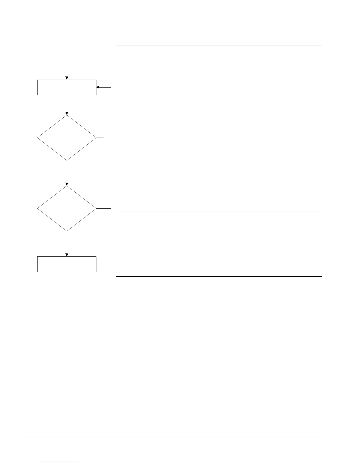
Circuit Controller Sequence of Operation
Unit power up
Circuit is in Off state
Next on?
Yes
Stage up now?
Yes
No
No
When the circuit is in the Off state the EXV is closed, compressor is off, and all fans
are off. The oil heater will be on at this time as long as oil is detected in the
separator.
If the compressor is ready to start when needed, the circuit status will be
Off:Ready
be
. When the circuit switch is off, the circuit cannot start and the status will
Off:Pumpdown Switch
.
If this compressor has the least starts, the other compressor is disabled for some
reason, or the other compressor is already running, then this compressor will be
designated as the next one on.
If there is a need for more cooling capacity, the compressor designated as next on
can start.
Is unit watercooled?
Yes
Preopen EXV
Start Compressor
No
If the unit is configured as watercooled, then the EXV preopen process must be
performed. Otherwise, this is skipped and the compressor can be started.
At this point, the EXV will perform a preopen. While the compressor is off, the EXV
is opened for a period of time to prime the evaporator and avoid low pressure at
startup. The circuit status will display
EXV Preopen
.
When the compressor starts, the EXV will open (if not already open) and hold at
3000 steps for 15 seconds.
If the unit is aircooled, depending on the OAT, a number of fans may be started with
the compressor to keep condenser pressure from climbing too fast.
The circuit status will normally be
Run: Disc SH Low
after the compressor starts.
OM WGS-5 WGS 130A to 190A 21
Run Compressor
Next off?
Yes
Stage down now?
Yes
When in the Run state, the compressor will load/unload as needed to satisfy the
load. The compressor will also load/unload to load balance with the other
compressor if it is running and not in a limited condition. However, it cannot load up
until the discharge superheat has been over 22 F for at least 30 seconds. After this,
the circuit status will be
Run:Normal
.
The EXV will operate in either Pressure Control or Superheat Control. In Pressure
Control, the evaporator pressure is controlled to a target pressure, which is adjusted
based on LWT and discharge superheat. In Superheat Control, the suction
superheat is controlled to a target that varies with discharge superheat.
No
If unit is aircooled, fans will be staged on and off to control the condenser pressure.
The condenser pressure is controlled to a target that is based on evaporator
pressure, with the target getting higher as the evaporator pressure gets higher.
No
If this compressor has the most run hours or the other compressor is already off,
then this compressor will be designated as the next one off.
If less cooling capacity is needed, the compressor designated as next off can shut
down. This condition may arise when either the LWT has dropped far enough below
the active set point or both circuits are running at a low capacity.
When the circuit does a normal shutdown, a pumpdown is performed. The EXV is
closed while the compressor continues to run. As soon as the pumpdown is
initiated, the compressor is unloaded to the minimum. The condenser fans
continue to control normally during this process. The circuit status during this time
Run:Pumpdown
is
.
Pumpdown circuit
After the evaporator pressure drops below the pumpdown pressure or enough time
has passed, the compressor and fans are shut off to end the pumpdown process.
The circuit status will normally be
Off:Cycle Timers
at this time.
22 WGS 130A to 190A OM WGS-5
Start-Up and Shutdown
Pre Start-up
1. Flush and clean the chilled-water system. Proper water treatment is required to prevent
corrosion and organic growth. A 20-mesh strainer is required at the evaporator chilledwater inlet and should be cleaned after system flushing.
Failure to flush, clean and provide system water treatment can damage the unit.
2. With the main disconnect open, check all electrical connections in control panel and
starter to be sure they are tight and provide good electrical contact. Connections are
tightened at the factory, but can loosen enough in shipment to cause a malfunction.
Lock and tag out all power sources when checking connections. Electrical shock
can cause severe personal injury or death..
3. Check and inspect all water piping. Make sure flow direction is correct and that piping
is made to the correct connection on evaporator and condenser.
4. Check that refrigerant piping on remote condensers is connected to the correct circuits
and not crossed and has been properly leak tested and evacuated.
5. Open all water flow valves to the condenser and evaporator.
6. Flush the cooling tower and system piping to be sure the system is clean. Start
evaporator pump and manually start condenser pump and cooling tower. Check all
piping for leaks. Vent the air from the evaporator and condenser water circuit, as well
as from the entire water system. The cooler circuit should contain clean, treated, noncorrosive water.
7. Check to see that the evaporator water temperature sensor is securely installed.
8. Make sure the unit control switch S1 is open OFF and the circuit switches CS1 and CS2
are open. Place the main power disconnect switch to ON. This will energize the
compressor sump heaters. Wait a minimum of 12 hours before starting the unit.
9. Measure the water pressure drop across the evaporator and condenser, and check that
water flow is correct (on pages 26 and 27) per the design flow rates.
10. Check the actual line voltage to the unit to m
compressor nameplate, within + 10%, and that phase voltage unbalance does not exceed
2%. Verify that adequate power supply and capacity is available to handle load.
11. Make sure all wiring and fuses are of the proper size. Also make sure that all interlock
wiring is completed per McQuay diagrams.
12. Verify that all mechanical and electrical inspections by code authorities have been
completed.
13. Make sure all auxiliary load and control equipment is operative and that an adequate
cooling load is available for initial start-up.
!
CAUTION
!
CAUTION
ake sure it is the same as called for on the
Start-up
1. Open the compressor discharge shutoff valves until backseated. Replace valve seal
caps.
2. Open the two manual liquid line shutoff valves (king valves).
OM WGS-5 WGS 130A to 190A 23

3. Verify that the compressor sump heaters have operated for at least 12 hours prior to
start-up. Crankcase should be warm to the touch.
4. Check that the MicroTech II controller is set to the desired chilled water temperature.
5. Start the system auxiliary equipment for the installation by turning on the time clock,
ambient thermostat and/or remote on/off switch and water pumps.
6. Switch on the unit circuit breakers.
7. Set circuit switches CS1 and CS2 to ON for normal operation.
8. Start the system by setting the unit system switch S1 to ON.
9. After running the unit for a short time, check the oil level in each compressor, rotation
of condenser fans (if any), and check for flashing in the refrigerant sight glass.
Weekend or Temporary Shutdown
Move circuit switches CS1 and CS2 to the OFF pumpdown position. After the compressors
have shut off, turn off the chilled water pump if not on automatic control from the chiller
controller or building automation system (BAS). With the unit in this condition, it will not
restart until these switches are turned back on.
Leave on the power to the unit (disconnect closed) so that the sump heaters will remain
energized.
Start-up after Temporary Shutdown
1. Start the water pumps.
2. Check compressor sump heaters. Compressors should be warm to the touch.
3. With the unit switch S1 in the ON position, move the circuit switches CS1 and CS2 to
the ON position.
4. Observe the unit operation for a short time, noting unusual sounds or possible cycling of
compressors.
Extended Shutdown
1. Close the manual liquid line shutoff valves.
2. After the compressors have shut down, turn off the water pumps.
3. Turn off all power to the unit.
4. Move the unit control switch S1 to the OFF position.
5. Close the discharge shutoff valves.
6. Tag all opened disconnect switches to warn against start-up before opening the
compressor suction and discharge valves.
7. Drain all water from the unit evaporator, condenser and chilled water piping if the unit
is to be shut down during the winter and exposed to below-freezing temperatures. To
help prevent excessive corrosion, do not leave the vessels or piping open to the
atmosphere over the shutdown period.
24 WGS 130A to 190A OM WGS-5
Start-up after Extended Shutdown
1. Inspect all equipment to see that it is in satisfactory operating condition.
2. Remove all debris that has collected on the surface of the condenser coils (remote
condenser models) or check the cooling tower, if present.
3. Open the compressor discharge valves until backseated. Always replace valve seal
caps.
4. Open the manual liquid line shutoff valves.
5. Check circuit breakers. They must be in the OFF position.
6. Check to see that the circuit switches CS1 and CS2 and the unit control switch S1 are in
the OFF position.
7. Close the main power disconnect switch. The circuit disconnects switches should be
off.
8. Allow the sump heaters to operate for at least 12 hours prior to start-up.
9. Start the chilled water pump and purge the water piping as well as the evaporator in the
unit.
10. Start the system auxiliary equipment for the installation by turning on the time clock,
ambient thermostat and/or remote on/off switch.
11. Check that the MicroTech II controller is set to the desired chilled water temperature.
12. Switch the unit circuit breakers to ON.
13. Start the system by setting the system switch S1 and the circuit switches to ON.
!
CAUTION
Most relays and terminals in the control center are powered when S1 is closed and the
control circuit disconnect is on. Therefore, do not close S1 until ready for start-up or serious
equipment damage can occur.
14. After running the unit for a short time, check the oil level in the compressor oil sight
glass and check the liquid line sight glass for bubbles.
OM WGS-5 WGS 130A to 190A 25
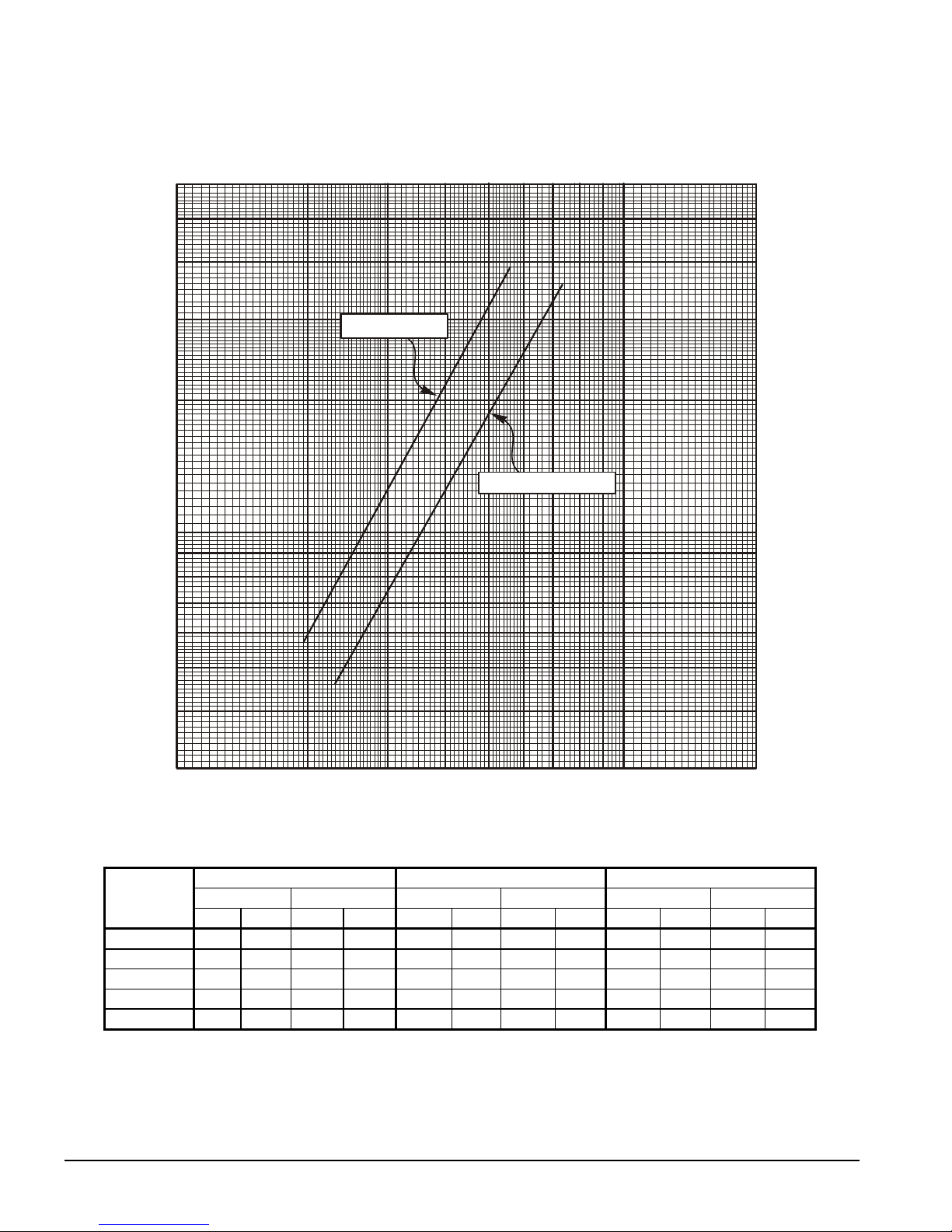
Figure 7, Evaporator Pressure Drop WGS 130 – WGS 190
Flow Rate (L/s)
6131925323844505763
60
126
180
50
40
30
20
10
9
8
Pressure Drop (ft of water)
7
6
5
WGS 130, 140
WGS 160, 170, 190
150
120
90
60
30
27
24
21
18
15
Pressure Drop (kPa)
4
3
100 200 300 400 500 600 700
800
900
1000
12
9
2000
Flow Rate (GPM)
Minimum Flow Nominal Flow Maximum Flow
WGS Model
130AW/AA
140AW/AA
160AW/AA
170AW/AA
190AW/AA
Note: Minimum, nominal, and maximum flows are at a 16F, 10F, and 6F chilled water temperature range respectively and at ARI tons.
Flow Rate Pressure Drop Flow Rate Pressure Drop Flow Rate Pressure Drop
gpm L/s Ft. kPa gpm L/s Ft. kPa gpm L/s Ft. kPa
195 12.3 5.8 17.4 312 19.7 13.5 40.4 520 32.9 33.9 101.1
211 13.4 6.7 20.0 338 21.4 15.6 46.6 563 35.6 39.0 116.5
235 14.9 4.6 13.8 376 23.8 10.8 32.3 627 39.7 27.3 81.6
254 16.1 5.3 15.9 407 25.8 12.5 37.3 678 42.9 31.6 94.2
273 17.3 6.1 18.1 437 27.7 14.2 42.5 728 46.1 35.9 107.2
26 WGS 130A to 190A OM WGS-5
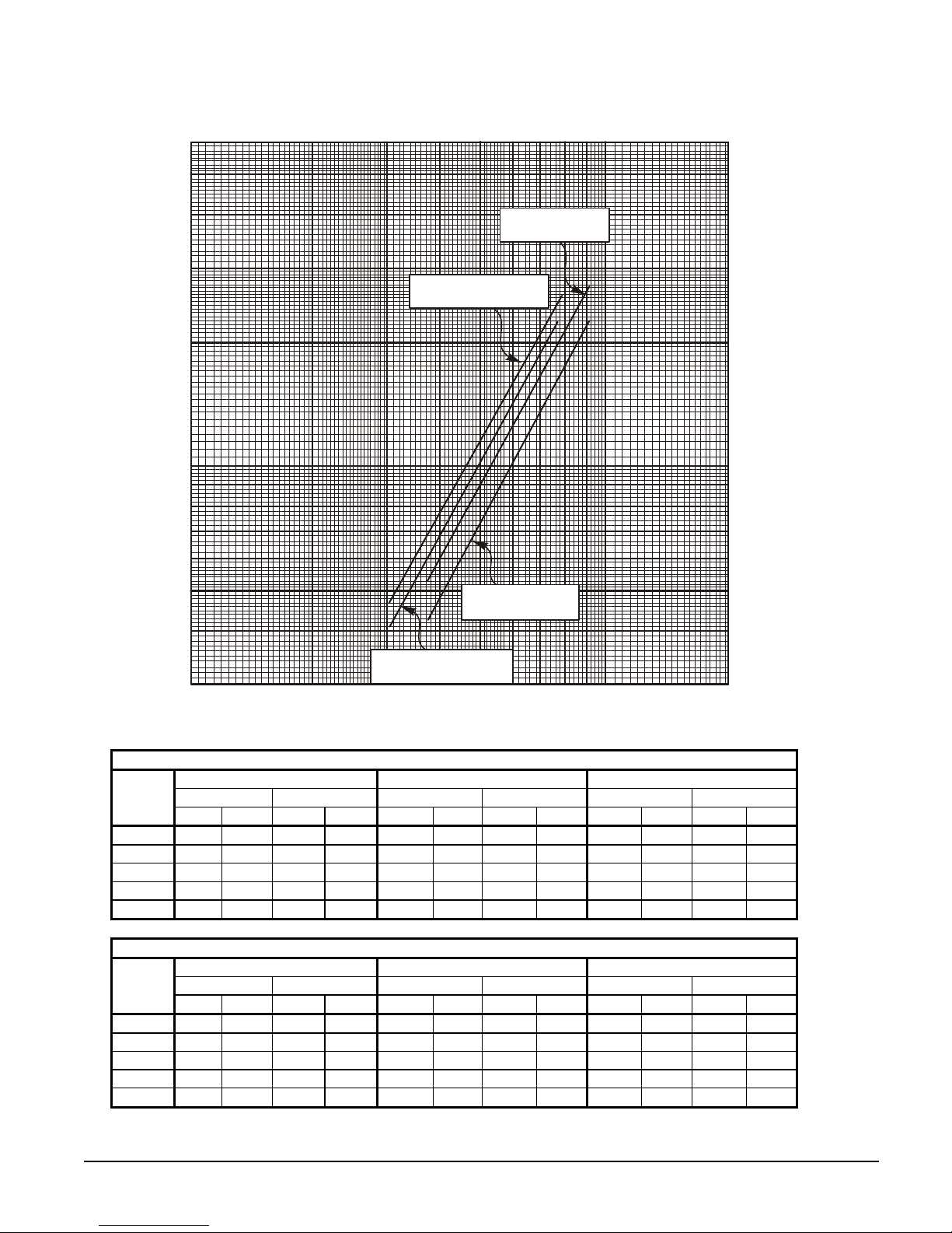
Figure 8, Condenser Pressure Drop WGS 130 – WGS 190
)
)
Flow Rate (L/s
6131925323844505763
60
126
180
Pressure Drop (ft of water)
WGS
Model
130AW
140AW
160AW
170AW
190AW
WGS
Model
130AW
140AW
160AW
170AW
190AW
50
40
WGS 170, 190
150
120
with Manifold
30
90
WGS 130, 140, 160
with Manifold
20
10
9
8
7
6
5
WGS 170, 190
60
30
27
24
21
18
15
without Manifold
4
12
WGS 130, 140, 160
3
100 200 300 400 500 600 700
without Manifold
800
900
1000
9
2000
Flow Rate (GPM
Pressure Drop Without Optional Condenser Manifold
Minimum Flow Nominal Flow Maximum Flow
Flow Rate Pressure Drop Flow Rate Pressure Drop Flow Rate Pressure Drop
gpm L/s Ft. kPa gpm L/s Ft. kPa gpm L/s Ft. kPa
304 19.2 4.1 12.2 390 24.7 6.5 19.3 650 41.1 16.0 47.9
304 19.2 4.1 12.2 422 26.7 7.4 22.2 704 44.5 18.5 55.1
304 19.2 4.1 12.2 470 29.8 9.0 26.9 784 49.6 22.4 66.8
372 23.5 4.3 12.8 509 32.2 7.9 23.7 848 53.7 19.8 59.1
372 23.5 4.3 12.8 546 34.6 9.0 26.9 911 57.6 22.5 67.1
Pressure Drop With Optional Condenser Manifold
Minimum Flow Nominal Flow Maximum Flow
Flow Rate Pressure Drop Flow Rate Pressure Drop Flow Rate Pressure Drop
gpm L/s Ft. kPa gpm L/s Ft. kPa gpm L/s Ft. kPa
304 19.2 4.7 14.0 390 24.7 7.4 22.0 650 41.1 18.5 55.1
304 19.2 4.7 14.0 422 26.7 8.5 25.3 704 44.5 21.3 63.5
304 19.2 4.7 14.0 470 29.8 10.3 30.7 784 49.6 25.8 77.1
372 23.5 5.3 15.8 509 32.2 9.4 28.1 848 53.7 23.8 71.1
372 23.5 5.3 15.8 546 34.6 10.7 32.0 911 57.6 27.1 80.9
Pressure Drop (kPa)
OM WGS-5 WGS 130A to 190A 27

Unit Controller
Unit Inputs/Outputs
Table 1, Analog Inputs
# Description Signal Source Range
1
2
3
4
5
C1 = Refrigerant Circuit #1, C2 = Refrigerant Circuit #2, UT = Unit
Table 2, Analog Outputs
# Description Output Signal Range
1
2
3
4
Table 3, Digital Inputs
# Description Signal Signal
1
2
3
4
5
6
7
8
Condenser EWT or Outdoor
Ambient Temp.
Demand Limit 4-20 mA Current 0 to 100% limit
Chilled Water Reset 4-20 mA Current
Leaving Evaporator Water Temp. Thermister (10k@25°C) -58 to 212°F
Entering Evaporator Water Temp. Thermister (10k@25°C) -58 to 212°F
Cooling Tower Bypass Valve Position 0 to 10 VDC 0 to 100%
Cooling Tower VFD Speed 0 to 10 VDC 0 to 100%
Open
Open
Unit Switch 0 VAC (Stop) 24 VAC (On)
Remote Switch 0 VAC (Stop) 24 VAC (Start)
Evaporator Water Flow Switch 0 VAC (No Flow) 24 VAC (Flow)
Mode Switch 0 VAC (Cool) 24 VAC (Ice)
Condenser Water Flow Switch 0 VAC (No Flow) 24 VAC (Flow)
Open
Open
Open
Thermister (10k@25°C) -58 to 212°F
0 to 10 degrees
60F max.
Table 4, Digital Outputs
# Description Load Output OFF Output ON
Evaporator Water Pump 1 Pump Contactor Pump OFF Pump ON
1
Evaporator Water Pump 2 Pump Contactor Pump OFF Pump ON
2
Condenser Water Pump 1 Pump Contactor Pump OFF Pump ON
3
Condenser Water Pump 2 Pump Contactor Pump OFF Pump ON
4
Tower Fan 1 Fan Contactor Fan OFF Fan ON
5
Tower Fan 2 Fan Contactor Fan OFF Fan ON
6
Remote Run Status All Circuits Off Any Circuit On
7
Alarm Remote Alarm No alarm Stop alarm
8
Unit Setpoints
The following parameters are retained during power off, are factory set to the Default value,
and can be adjusted to any value in the Range column.
The Type defines whether the setpoint is part of a coordinated set of duplicate setpoints in
different controllers. Types are as follows:
N = Normal setpoint – Not copied from, or copied to, any other controller
M = Master setpoint – Setpoint is copied to all controllers in the “Sent To” column
The PW (password) column indicates the password level that must be active in order to
change the setpoint. Passwords are as follows:
O = Operator [0100] M = Manager (8745)
28 WGS 130A to 190A OM WGS-5
Toggle: Setpoints that have two choices, such as ON and OFF are toggled between the two
settings using the Up or Down keys on the controller.
NOTE: in some software versions the terms “inhibit” and “hold” are used interchangeably.
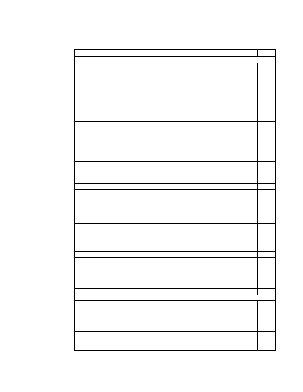
Table 5, Unit Controller Setpoints
Description Default Range Type PW
Unit
Unit Enable OFF OFF, ON N O
Unit Mode Cool Cool, Ice, Test M O
Control source Switches Switches, Keypad, Network N O
Available Modes Cool
Cool LWT
Ice LWT
Start Delta T
Stop Delta T
Stage Up Delta T
Stage Down Delta T
Max Pulldown
Evap Recirc Timer 30 0 to 300 seconds N M
Evap Pump Select #1 Only #1 Only, #2 Only, Auto N M
Water-cooled Yes No, Yes N M
Cond Recirc Timer (water-
cooled only)
Cond Pump Select (watercooled only)
LWT Reset Type NONE NONE, RETURN, 4-20mA, OAT N M
Max Reset
Start Reset Delta T
Soft Load Off Off, On N M
Begin Capacity Limit 40% 20-100% N M
Soft Load Ramp 20 min 1-60 minutes N M
Demand Limit Off Off, On N M
Low OAT Operation
(air-cooled only)
Low Ambient Lockout (air
cooled only)
Ice Time Delay 12 1-23 hours N M
Clear Ice Timer No No,Yes N M
Evap LWT sensor offset 0 -5.0 to 5.0 deg N M
Evap EWT sensor offset 0 -5.0 to 5.0 deg N M
Cond EWT/OAT sensor offset 0 -5.0 to 5.0 deg N M
Cond LWT sensor offset 0 -5.0 to 5.0 deg N M
Units
BAS Protocol Modbus BACnet, LonWorks, Modbus N M
Ident number 1 0-200 N M
Baud Rate 19200 1200,2400,4800,9600,19200 N M
Compressors
Sequence # Cir 1 1 1-2 M M
Sequence # Cir 2 1 1-2 M M
Max Comps ON 2 1-2 N M
Start-start timer 20 min 15-60 minutes M M
Stop-start timer 5 min 3-20 minutes M M
Pumpdown Pressure 25 psi 10 to 40 psi M M
Pumpdown Time Limit 120 sec 0 to 180 sec M M
Light Load Stg Dn Point 25% 20 to 50% M M
44 F 30(40) to 60 F
25 F 20 to 38F
10 F 0 to 10 F
1.5 F 0 to 3 F
2 F 0 to 3 F
1 F 0 to 3 F
5 F/min 0.5-5.0 F /min
30 0 to 300 seconds N M
#1 Only #1 Only, #2 Only, Auto N M
0 F 0 to 20 F
10 F 0 to 20 F
No No, Yes N M
55 F -10(35) to 70 F
F/psi F/psi, C/kPa
Continued next page.
Cool, Cool w/Glycol, Cool/Ice
w/Glycol, ICE w/Glycol, TEST
N T
N O
N O
M O
M O
M O
M O
M M
N M
N M
N M
N M
OM WGS-5 WGS 130A to 190A 29
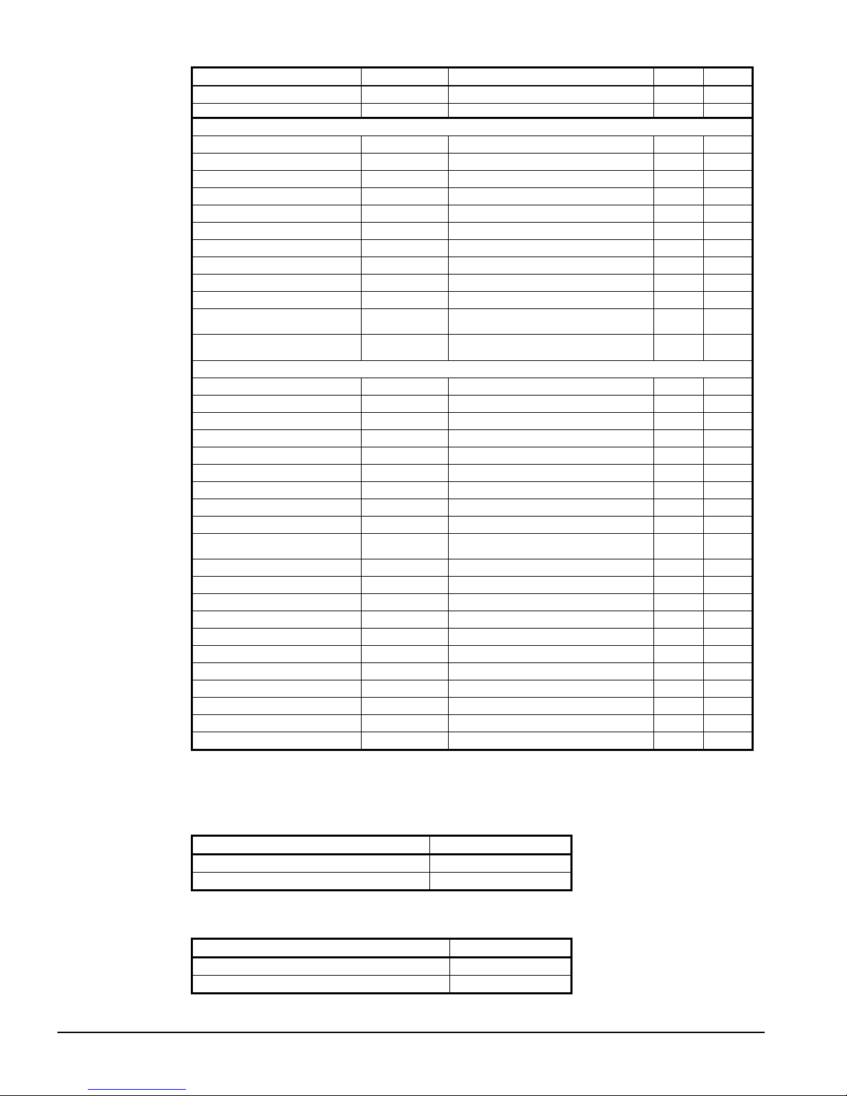
Description Default Range Type PW
Stage Up Delay 5 min 0 to 60 min M M
Disc. Temp Sensor Type PT1000 NTC, PT1000 M M
Alarms
Low Evap Pressure-Unload 28 psi [0,26] to 45 psi M M
Low Evap Pressure-Hold 30 psi [0,28] to 45 psi M M
Low Oil Level Delay 120 sec 10-180 sec M M
High Oil Press Diff Delay 15 sec 0-90 sec M M
High Discharge Temperature
High Lift Pressure Delay 5 sec 0 to 30 sec M M
Evaporator Water Freeze
Evaporator Flow Proof 3 sec 3 to 10 sec N M
Recirculate timeout 3 min 1 to 10 min. N M
Startup Timer 60 sec 20 to 90 sec. M M
Condenser Water Freeze
(water cooled only)
Condenser Flow Proof (water
cooled only)
Cooling Tower(available for Water cooled only)
Tower Control None None, Temperature N M
Tower Stages 2 0 to 2 N M
Stage #1 On
Stage #2 On
Stage Differential
Stage Up Time 2 min 1 to 60 min N M
Stage Down Time 5 min 1 to 60 min N M
Stage Fan Down @ 20% 0 to 100% N M
Stage Fan Up @ 80% 0 to 100% N M
Valve/VFD Control None
Valve Type NC to tower NC, NO N M
Valve Setpoint
Valve Deadband
Minimum Start Position 0% 0 to 100% N M
Minimum Position @
Maximum Start Position 100% 0 to 100% N M
Maximum Position @
Valve Control Range (Min) 10% 0 to 100% N M
Valve Control Range(Max) 90% 0 to 100% N M
Error Gain 25 10 to 99 N M
Slope Gain 25 10 to 99 N M
200 F
36 F 15(36) to 42 F
38 F 34 to 42 F
3 sec 3 to 10 sec N M
70 F 40 to 120 F
75 F 40 to 120 F
3.0 F 1.0 to 10.0 F
None, Valve Setpoint, Valve Stage,
VFD Stage, Valve SP/VFD Stage
65 F 60 to 120 F
2.0 F 1.0 to 10.0 F
60 F 0 to 100 F
90 F 0 to 100 F
150 to 200 F M M
N M
N M
N M
N M
N M
N M
N M
N M
N M
N M
Auto Adjusted Ranges
The following settings have different ranges of adjustment based on other settings.
Table 6, Cool LWT
Unit Mode = Cool 40 to 60oF
Unit Mode = Cool w/Glycol, Ice w/ Glycol 20 to 60oF
Table 7, Evaporator Water Freeze
Unit Mode = Cool 34 to 42oF
Unit Mode = Cool w/Glycol, Ice w/ Glycol 15 to 42oF
30 WGS 130A to 190A OM WGS-5
Mode Range
Mode Range
 Loading...