

Page 1
Operating Manual
Group: Chiller
Part Number: 330599503
Effective: October 2004
Supersedes: OM WGS
Water-Cooled Screw Compressor Chillers
WGS 130AW To WGS 190AW, Packaged Water-Cooled Chiller
WGS 130AA To WGS 190AA, Chiller with Remote Condenser
120 to 200 Tons, 420 to 700 kW
R-134a, 60 Hz
Software Version WGSD30101C
OM WGS-1
Page 2
Table of Contents
Introduction........................................3
General Description .....................................3
Nomenclature...............................................3
Definitions...........................................4
Wiring Diagrams................................8
Control Panel Layout......................10
MicroTech II Controller..............13
System Arch itecture ...................................13
General Description ...................................14
Sequence of Operation ....................16
Start-Up and Shutdown...................22
Pre Start-up ................................................22
Start-up.......................................................22
Weekend or Temporary Shutdown.............23
Start-up after Temporary Shutdown...........23
Extended Shutdown....................................23
Start-up after Extended Shutdown..............23
Unit Controller.................................27
Unit Inputs/Outputs....................................27
Unit Setpoints.............................................27
Circuit Controller............................30
Circuit Inputs and Outputs .........................30
Circuit Setpoint Table ................................31
Alarms, W arnings, Events...............32
Stop Alarms (Shutdown)............................32
Events (Limit)............................................34
Unit Controller Functions...............35
Unit Enable ................................................36
Unit Mode Selection ..................................37
Unit States..................................................38
Evaporator Pump Control...........................39
Leaving Water Temperature (LWT) Reset..40
Planned Unit Capacity Overrides...............42
Condenser Pump and Tower Control..........43
Cooling Tower Control...............................44
Evaporative Condenser Control.................46
Circuit Controller Functions.......... 48
Refrigerant Calculations.............................48
Compressor Control...................................49
Internal Capacity Overrides........................52
Slide Positioning ........................................53
Expansion Valve Control............................55
Oil Heater Control......................................59
Starter Communications.............................59
Condenser Fan Control...............................61
Digital Output Control................................62
Using the Controller...................................63
Security ......................................................65
Entering Passwords....................................65
Editing Setpoints........................................65
Clearing Alarm s..........................................65
Menu Descriptions...........................66
Unit Controller...........................................66
Circuit Controller.......................................80
Editing Review...........................................86
BAS Interface...................................87
Troubleshooting Chart....................88
Troubleshooting Chart................................88
Unit controllers are LONMARK
certified with an optional L
communications module.
Illustrations and data cover McQuay International products at the time of publication and we reserve the right to
make changes in design and construction at anytime without notice.
The following are trademarks or registered trademarks of their respective companies:
BACnet from ASHRAE; L
GeneSys, McQuay and MicroTech II from McQuay International.
2 WGS 130A to WGS 190A OM WGS-1
2004 McQuay International
ONMARK and LONWORKS from Echelon Corporation;
ONWORKS
Page 3

Introduction
General Description
McQuay Model WGS water chillers are designed for indoor installations and are available
with factory-mounted water-cooled condensers (Model WGS AW), or arranged for use with
remote air-cooled or evaporative condensers (Model WGS AA). Each water-cooled unit
(WGS-AW) is completely assembled and factory wired before factory evacuation, charging
and testing. The units consist of two semi-hermetic rotary screw compressors, a two-circuit
shell-and-tube evaporator, two shell-and-tube water-cooled condensers, and complete
refrigerant piping.
Units manufactured for use with remote condensers (Models WGS-AA) have all refrigerant
specialties factory-mounted and have two sets of connection points for refrigerant discharge
and liquid lines to and from the remote condenser. Discharge valves are included
Each circuit’s liquid line components are manual liquid line shutoff valve, charging valve,
filter-drier, liquid line solenoid valve, sight glass/moisture indicator, and electronic
expansion valve.
The electrical control center includes a MicroTech II microprocessor control system and
equipment protection and operating controls necessary for dependable, automatic operation.
The compressor circuits are equipped with individual circuit breakers and a unit disconnect
switch is available as an option over the standard power block.
Water-Cooled Condensing
Rotary Screw Compressor
Nominal Capacity (Tons)
Global
Nomenclature
W G S 130 - A W
W = Water-Cooled Condenser
A = Unit Less Condenser
Design Vintage
OM WGS-1 WGS 130A to 190A 3
Page 4

Definitions
Active Setpoint
The active setpoint is the setting in effect at any given moment. This variation occurs on
setpoints that can be altered during normal operation. Resetting the chilled water leaving
temperature setpoint by one of several methods, such as return water temperature, is an
example.
Active Capacity Limit
The active setpoint is the setting in effect at any given moment. Any one of several external
inputs can limit a compressor’s capacity below its maximum value.
Condenser Recirc Timer
A timing function, with a 30-second default, that holds off any reading of condenser water
for the duration of the timing setting. This delay allows the water sensors (especially water
temperatures) to take a more accurate reading of the condenser water system conditions.
Condenser Saturated Temperature Target
The saturated condenser temperature target is calculated by first using the following
equation:
Sat condenser temp target raw = 0.833(evaporator sat temp) + 68.34
The “raw” value is the initial calculated value. This value is then limited to a range defined
by the Condenser Saturated Temperature Target minimum and maximum setpoints. These
setpoints simply cut off the value to a working range, and this range can be limited to a
single value if the two setpoints are set to the same value.
CPU Error
These are problems caused by a malfunction of the central processing unit.
Dead Band
The dead band is a set of values associated with a setpoint such that a change in the
variable occurring within the dead band causes no action from the controller. For example,
if a temperature setpoint is 44°F and it has a dead band of ± 2 degrees, nothing will happen
until the measured temperature is less than 42°F or more than 46°F.
DIN
Digital input, usually followed by a number designating the number of the input.
Discharge Superheat
Discharge superheat shall be calculated for each circuit using the following equation:
Discharge Superheat = Discharge Temperature – Condenser Saturated Temperature
Error
In the context of this manual, “Error” is the difference between the actual value of a
variable and the target setting or setpoint.
Evaporator Approach
The evaporator approach is calculated for each circuit. The equation is as follows:
Evaporator Approach = LWT – Evaporator Saturated Temperature
4 WGS 130A to 190A OM WGS
Page 5

Evap Recirc Timer
A timing function, with a 30-second default, that holds off any reading of chilled water for
the duration of the timing setting. This delay allows the chilled water sensors (especially
water temperatures) to take a more accurate reading of the chilled water system conditions.
EXV
Electronic expansion valve, used to control the flow of refrigerant to the evaporator,
controlled by the circuit microprocessor.
High Saturated Condenser – Hold Value
High Cond Hold Value = Max Saturated Condenser Value – 5°F
This function prevents the compressor from loading whenever the pressures approach
within 5 degrees of the maximum discharge pressure. The purpose is to keep the
compressor online during periods of possibly temporary elevated pressures.
High Saturated Condenser – Unload Value
High Cond Unload Value = Max Saturated Condenser Value – 3°F
This function unloads the compressor whenever the pressures approach within 3 degrees of
the maximum discharge pressure. The purpose is to keep the compressor online during
periods of possibly temporary elevated pressures.
High Superheat Error
The degrees of temperature difference between 40°F and the actual discharge temperature.
Light load Stg Dn Point
The percent load point at which one of two operating compressors will shut off, transferring
the unit load to the remaining compressor.
Load Limit
An external signal from the keypad, the BAS or a 4-20 ma signal that limits the compressor
loading to a designated percent of full load. Frequently used to limit unit power input.
Load Balance
Load balance is a technique that equally distributes the total unit load among the running
compressors.
Low Ambient Lockout
Prevents the unit from operating (or starting) at ambient temperatures below the setpoint.
Low Pressure Hold Setpoint
The psi evaporator pressure setting at which the controller will not allow further
compressor loading.
Low/High Superheat Error
The difference between actual evaporator superheat and the superheat target.
LWT
Leaving water temperature. The “water” is any fluid used in the chiller circuit.
OM WGS-1 WGS 130A to 190A 5
Page 6

LWT Error
Error in the controller context is the difference between the value of a variable and the
setpoint. For example, if the LWT setpoint is 44°F and the actual temperature of the water
at a given moment is 46°F, the LWT error is +2 degrees.
LWT Slope
The LWT slope is an indication of the trend of the water temperature. It is calculated by
taking readings of the temperature every few seconds and subtracting them from the
previous value, over a rolling one-minute interval.
ms
Milli-second
Maximum Saturated Condenser Temperature
The maximum saturated condenser temperature allowed is calculated based on the
compressor operational envelope.
NC
Normally closed - usually refers to a contactor or valve.
NO
Normally open - usually refers to a contactor. or valve.
OAT
Outside ambient air temperature.
Offset
Offset is the difference between the actual value of a variable (such as temperature or
pressure) and the reading shown on the microprocessor as a result of the sensor signal. See
notes on page 32 for explanation of sensor off set.
pLAN
Peco Local Area Network is the proprietary name of the network connecting the control
elements.
Rapid Stop
A compressor stop process that circumvents the normal pumpdown cycle.
Refrigerant Saturated Te mperature
Refrigerant saturated temperature is calculated from the pressure sensor readings for each
circuit. The pressure is fitted to an R-134a temperature/pressure curve to determine the
saturated temperature.
Soft Load
Soft Load is a control sub-routine that allows the chiller to load up gradually. It requires
setpoint inputs of selecting it by Yes or No inputs, by selecting the percent load to start
ramping up, and by selecting the time to ramp up to full load (up to 60 minutes).
SP
Setpoint
SSS
Solid state starter as used on McQuay screw compressors.
Suction Superheat
Suction superheat is calculated for each circuit using the following equation:
Suction Superheat = Suction Temperature – Evaporator Saturated Temperature
6 WGS 130A to 190A OM WGS
Page 7

Stage Up/Down Accumulator
The accumulator can be thought of as a bank storing occurrences that indicate the need for
an additional fan.
Stageup/Stagedown Delta-T
Staging is the act of starting or stopping a compressor or fan when another is still operating.
Startup and Stop is the act of starting the first compressor or fan and stopping the last
compressor or fan. The Delta-T is the “dead band” on either side the setpoint in which no
action is taken.
Stage Up Delay
The time delay from the start of the first compressor to the start of the second.
Startup Delta-T
Number of degrees above the LWT setpoint required to start the first compressor.
Stop Delta-T
Number of degrees below the LWT setpoint required for the last compressor to stop.
VAC
Volts, Alternating current, sometimes noted as vac.
VDC
Volts, Direct current, sometimes noted as vdc.
VFD
Variable Frequency Drive, a device used to vary an electric motor’s speed.
OM WGS-1 WGS 130A to 190A 7
Page 8
Wiring Diagrams
A
A
A
A
A
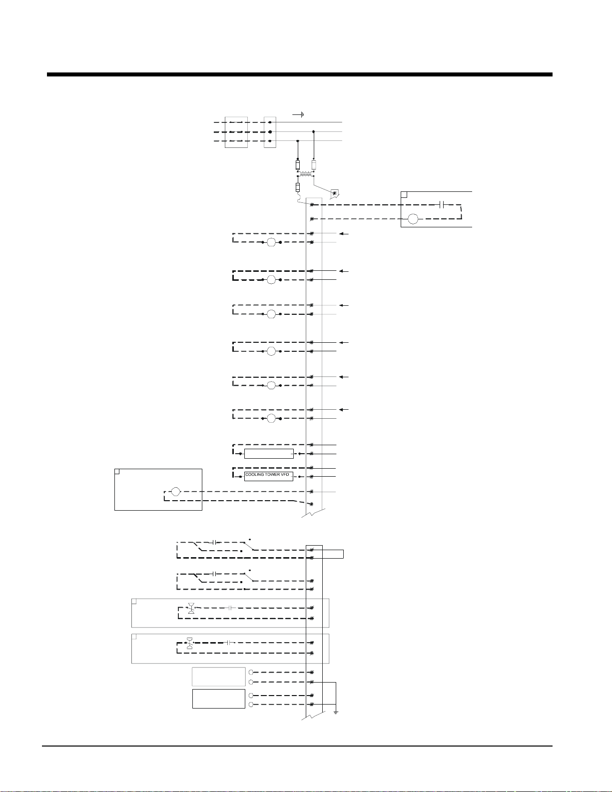
Figure 1, WGS 130AW – 190AW Field Wiring Diagram (Optional Single Point Connection)
3 PHASE
POWER
SUPPLY
DISCONNECT
(BY OTHERS)
UNIT MAIN
TERMINAL BLOCK
GND LUG
TO COMPRESSOR(S)
NOTE: ALL FIELD WIRING TO BE
INSTALLED AS NEC CLASS 1
WIRING SYSTEM WITH CONDUCTOR
RATED 600 VOLTS
FACTORY SUPPLIED ALARM
FIELD WIRED
ALARM BELL
OPTION
ABR
LARM BELL RELAY
FUSED CO N T RO L
CIRCUIT TRANSFORMER
CHWR
EVAP. PUMP RELAY #1
(BY OTHERS)
120 VAC 1.0 AMP MAX
CHWR
EVAP. PUMP RELAY #2
(BY OTHERS)
120 VAC 1.0 AMP MAX
CWR
COND. PUMP RELAY #1
(BY OTHERS)
120 VAC 1.0 AMP MAX
CWR
COND. PUMP RELAY #2
(BY OTHERS)
120 VAC 1.0 AMP MAX
M11
TOWER FAN #1
(BY OTHERS)
120 VAC 1.0 AMP MAX
M12
TOWER FAN #2
(BY OTHERS)
120 VAC 1.0 AMP MAX
COOLING TOWER BYPASS
(BY OTHERS)
(BY OTHERS)
FU4 FU5
120 VAC
FU7
TB1
(115 VAC)
1
2
82
2
85
2
86
2
87
2
88
2
89
2
78
77
80
79
81
75
TB1-2
N
24 VAC
120 VAC
N
120 VAC
N
120 VAC
N
120 VAC
N
120 VAC
N
120 VAC
N
0-10VDC
N
0-10VDC
BELL
12
LARM BELL
RELAY
COM NO
LARM BELL OPTION
TIME
REMOTE STOP
SWITCH
(BY OTHERS)
ICE MODE
SWITCH
(BY OTHERS)
EVAP. FLOW
SWITCH
(BY OTHERS)
*MANDATORY IF FACTORY FLOW SWITCH OPTION IS NOT SELECTED
COND. FLOW
SWITCH
(BY OTHERS)
*MANDATORY IF FACTORY FLOW SWITCH OPTION IS NOT SELECTED
CLOCK
NOR. OPEN PUMP AUX.
CONTACTS (OPTIONAL)
NOR. OPEN PUMP AUX.
CONTACTS (OPTIONAL)
4-20MA FOR
EVAP. WATER RESET
(BY OTHERS)
4-20MA FOR
DEMAND LIMIT
(BY OTHERS)
UTO
ON
MANUAL
UTO
ON
MANUAL
OFF
OFF
TB1
(24 VAC OR 30 VDC)
60
66
IF REMOTE STOP CONTROL
897
IS USED, REMOVE LEAD 897
FROM TERM. 40 TO 53.
60
68
60
67
60
76
+
-
+
-
72
70
71
70
DWG. 330588201 REV . 0B
GND
8 WGS 130A to 190A OM WGS
Page 9
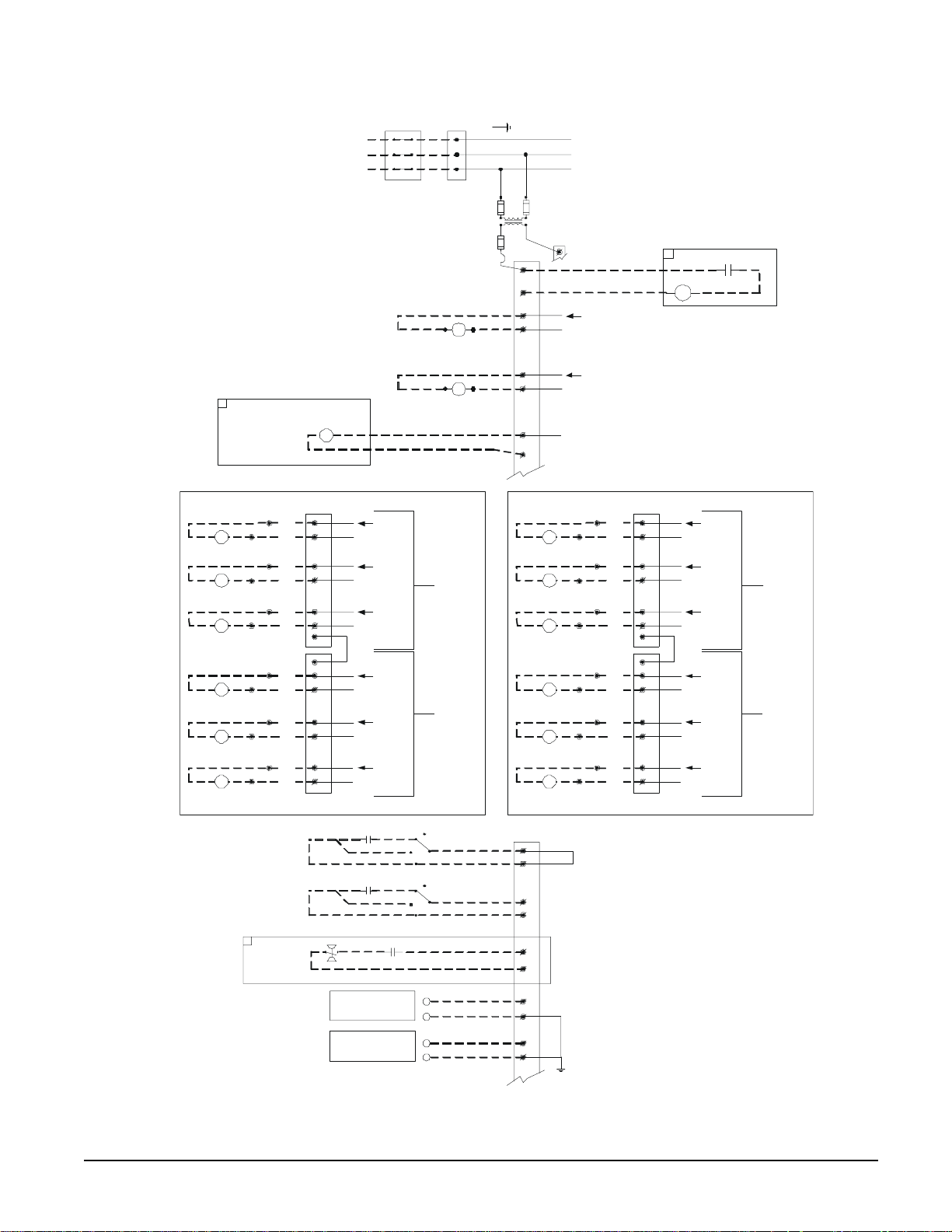
Figure 2, WGS 130AA – 190AA Field Wiring Diagram (Remote Air-cooled Condenser)
UNIT MAIN
A
A
A
A
3 PHASE
POWER
SUPPLY
DISCONNECT
(BY OTHERS)
TERMINAL BLOCK
GND LUG
TO COMPRESSOR(S)
NOTE: ALL FIELD WIRING TO BE
INSTALLED AS NEC CLASS 1
WIRING SYSTEM WITH CONDUCTOR
RAT E D 60 0 V OLTS
FACTORY SUPPLIED ALARM
ALARM BELL
OPTION
CIRCUIT #1
M11
CONDENSER FAN
CONTACTOR COIL #1
M12
CONDENSER FAN
CONTACTOR COIL #2
M13
CONDENSER FAN
CONTACTOR COIL #3
M14
CONDENSER FAN
CONTACTOR COIL #4
M15
CONDENSER FAN
CONTACTOR COIL #5
M16
CONDENSER FAN
CONTACTOR COIL #6
FIELD WIRED
TB6
92
144
98
145
93
146
98
145
94
148
98
145
95
150
98
145
96
152
98
145
97
154
98
145
REMOTE STOP
SWITCH
(BY OTHERS)
ICE MODE
SWITCH
(BY OTHERS)
ABR
ALARM BELL RELAY
NO1
2
NO2
2
NO3
2
C
C
NO4
2
NO5
2
NO6
2
FUSED CONTROL
CIRCUIT T RANSFORMER
EVAP. PUMP RELAY #1
120 VAC 1.0 AMP MAX
EVAP. PUMP RELAY #2
120 VAC 1.0 AMP MAX
120 VAC
N
120 VAC
N
120 VAC
N
(LOCATED ON
CONTROLLER)
120 VAC
N
120 VAC
N
(LOCATED ON
CONTROLLER)
120 VAC
N
TIME
CLOCK
UTO
ON
MANUAL
UTO
ON
MANUAL
OFF
OFF
CHWR
(BY OTHERS)
CHWR
(BY OTHERS)
J12
CIRCUIT
J13
CIRCUIT
FU4
120 VAC
FU7
TB1
(115 VAC)
CIRCUIT #2
CONDENSER FAN
CONT A CTOR COIL #1
CONDENSER FAN
CONTA CTOR COIL #2
CONDENSER FAN
CONTA CTOR COIL #3
CONDENSER FAN
CONT A CTOR COIL #4
CONDENSER FAN
CONTA CTOR COIL #5
CONDENSER FAN
CONTA CTOR COIL #6
TB1
(24 VAC)
FU5
TB1-2
1
2
82
2
85
2
81
120 VAC
N
120 VAC
N
24 VAC
BELL
2
1
LARM BELL OPTION
LARM BELL
RELAY
COM
NO
75
TB7
92
244
245
246
245
248
245
250
245
252
245
254
245
NO1
2
NO2
2
NO3
2
C
C
NO4
2
NO5
2
NO6
2
98
M21
93
98
M22
94
98
M23
95
98
M24
96
98
M25
97
98
M26
60
66
IF REMOTE STOP CONTROL
897
IS USED, REMOVE LEAD 897
FROM TERM. 40 TO 53.
N
N
N
N
N
N
120 VAC
120 VAC
120 VAC
120 VAC
120 VAC
120 VAC
J12
(LOCATED ON
CIRCUIT
CONTROLLER)
J13
(LOCATED ON
CIRCUIT
CONTROLLER)
60
68
EVAP. FLOW
SWITCH
(BY OTHERS)
*MANDATORY IF FACTORY FLOW SWITCH OPTION IS NOT SELECTED.
NOR. OPEN PUMP AUX.
CONTACTS (OPTIONAL)
4-20MA FOR
EVAP. WATER RESET
(BY OTHERS)
4-20MA FOR
DEMAND LIMIT
(BY OTHERS)
+
-
+
-
60
67
72
70
71
70
GND
DWG. 330588101 REV. 0C
OM WGS-1 WGS 130A to 190A 9
Page 10
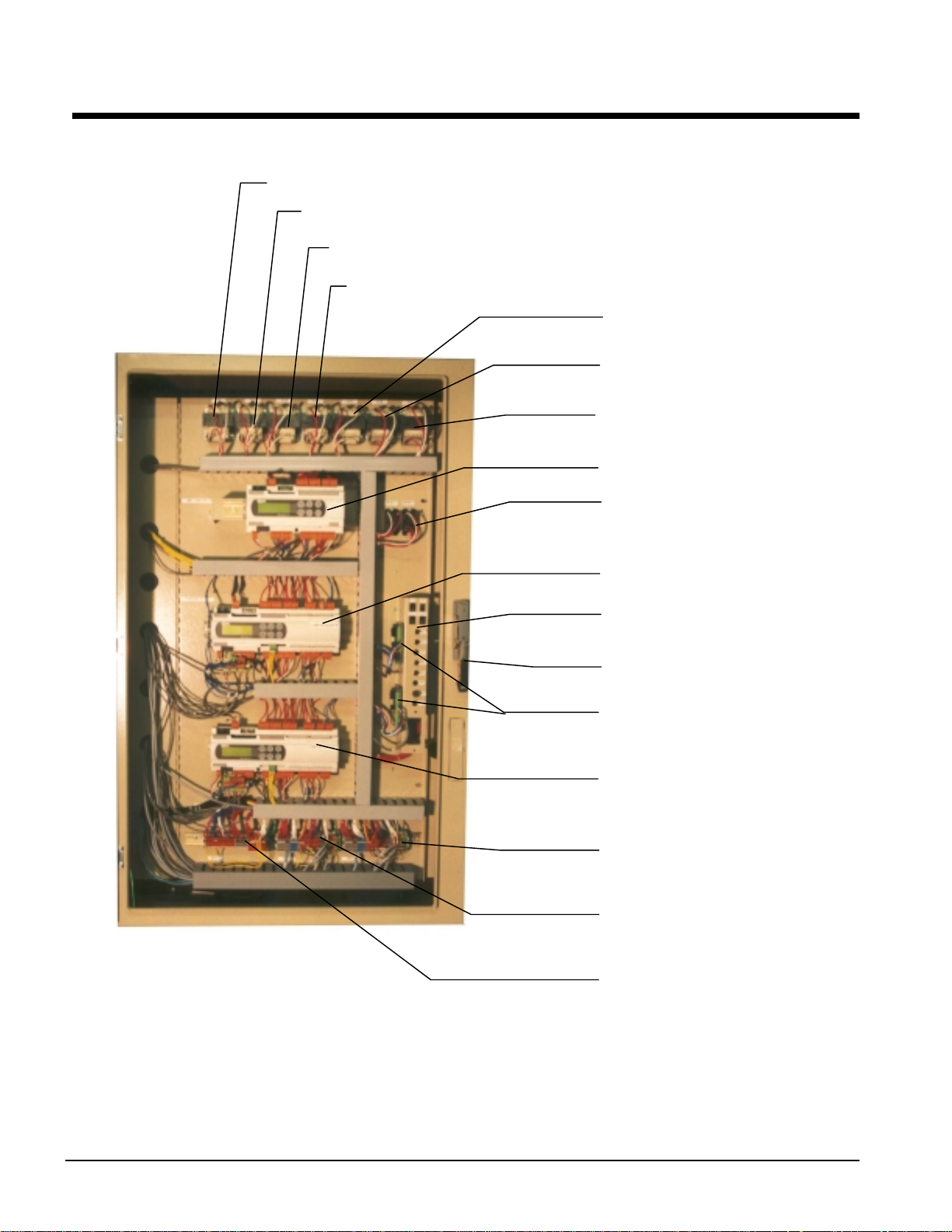
Control Panel Layout
r
r
Figure 3, Outer (Microprocessor) Panel
T2, Unit Controlle
T13, Circ#1 Controller
T14, Circ#1 Load Solenoid
T15, Circ#1 EXV Power
T23, Circ#2 Controlle
T24, Circ#2 Load Solenoid
T25, Circ#2 EXV Power
Unit Controller
MHPR11 &12, Mechanical
High Pressure Rel ay
Circ#1 Controller
Circuit Breaker &
Switch Panel
External Disconnect Handle
Circ#1 & 2 EXV Drivers
Circ#2 Controller
TB3, Circ#2 Controller
Terminal Board
TB2, Circ#1 Controller
Terminal Board
TB1 Unit Controller
Terminal Board
NOTES:
1. Transformers T2 through T25 are class 100, 120V to 12V.
2. Switches for MHPR 11 and 12 (Mechanical High Pressure Switches) are located on the compressors.
3. Mechanical High Pressure Switches Open at 310 psi, Close at 250 psi.
10 WGS 130A to 190A OM WGS
Page 11
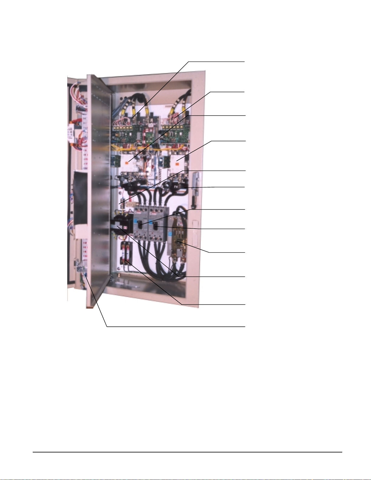
Figure 4, Inner (Power) Panel (Opti onal Single-Point Power wi th Disconnect Switches
Shown)
Circ#1 Solid State Starter
Circ#2 Solid State Starter
SSS1 Bypass Contactor
SSS2 Bypass Contactor
Secondary Fuses
External Disconnect Handle
Circ#1 Circuit Breaker
Circ#2 Circuit Breaker
Unit Disconnect Switch
W/ External Handle
T1, Supply Voltage to
120V Transf ormer
Primary Fuses
Outside (Microprocessor) Panel
OM WGS-1 WGS 130A to 190A 11
Page 12
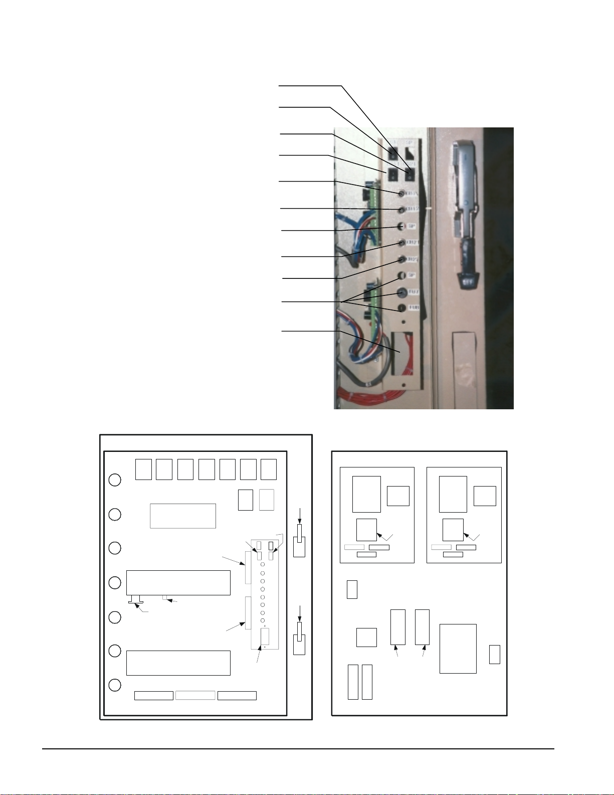
Figure 5, Circuit Breaker/Fuse Panel
d
n
t
r
Open Location
S1 Main Unit On-Off Switch
CS2, Circuit#2 On-Off Switch
CS1, Circuit#1 On-Off Switch
CB11 Circ#1 Circuit Breaker
CB12, Circ#1 Sump Heater
Open Locatio
CB21, Circ#2 Circui
CB22, Circ#2 Sump Heate
Open Locations
Location for Optional
115V Receptacle
OUTER PANEL INNER PANEL
T13T2 T14 T15 T23 T24 T25
UNIT
CONTROLLER
EXV.
DRIVER
#1
CIRCUIT CONTROLLER
#1
MODBUS CARD
CONVERTER BOARD
EXV.
DRIVER
#2
CIRCUIT CONTROLLER
#2
TB1
TB11 TB21
MHPR1MHPR
CS1
S1S
REC
OPTION
2
CS2
CB11
CB12
SP
CB21
CB22
SP
FU7
F3
SINGLE
POINT
OR
CIR. #1
DS
HANDLE
(MULTI-
POINT)
P
CIR. #2
DS
HANDLE
(MULTI-
POINT)
SSS #1 SSS #2
D3
CT2
T1
F
U
5
CONTACTOR
CT1
THERM-
ISTOR
CARD
BYPASS
C
B
1
(DS1 DS2
MULTIPOINT
POWER)
CT3
C
B
2
CONTR.
BRD.
CT3
F
U
6
F
U
4
D3
CONTR.
BRD.
CT2
DS1
CONTACTOR
CT1
THERM-
ISTOR
CARD
BYPASS
G
N
D
330589001 REV. 00 - Legen
12 WGS 130A to 190A OM WGS
Page 13
MicroTech II Controller
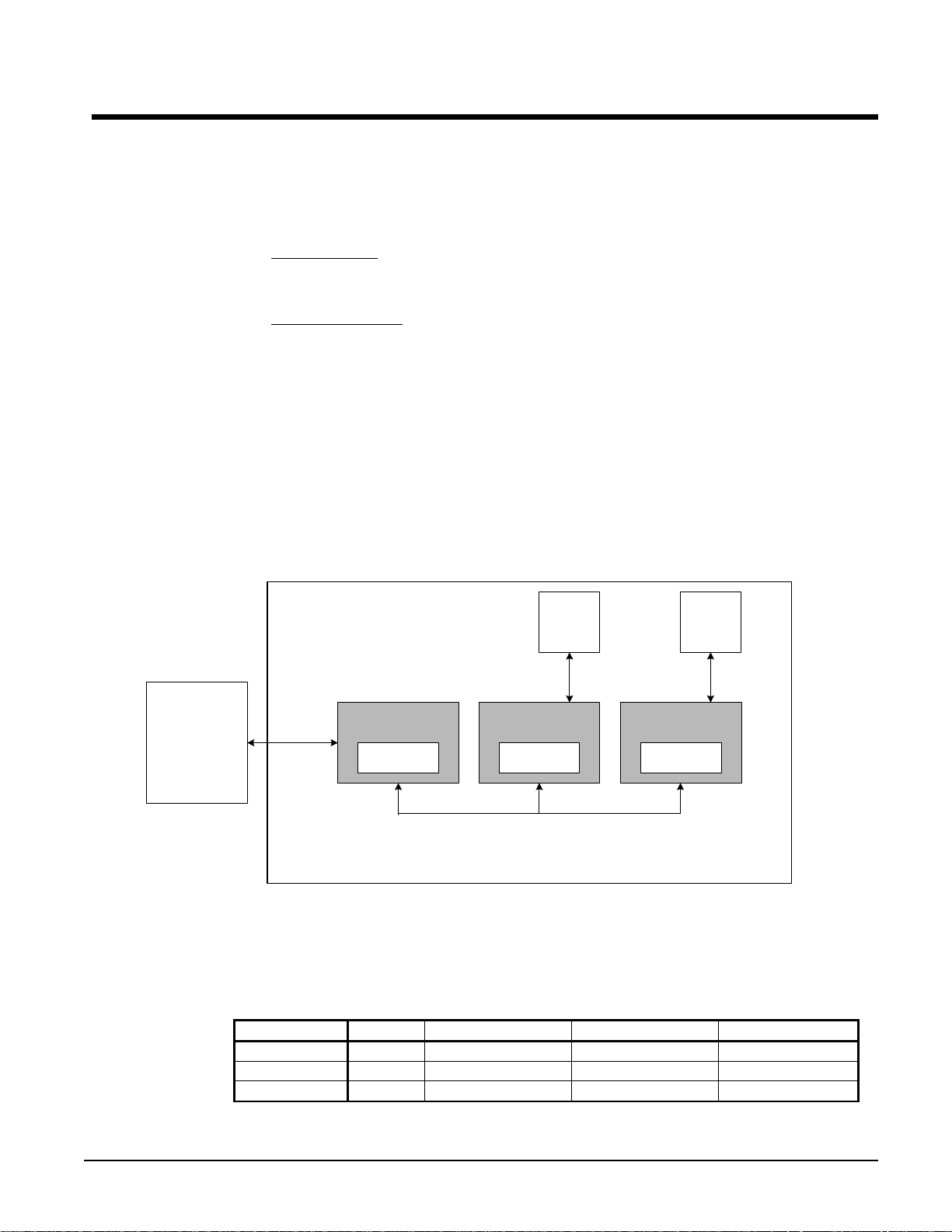
System A rchitecture
The WGS MicroTech ΙΙ distributed control system consists of multiple microprocessorbased controllers that provide monitoring and control functions required for the controlled,
efficient operation of the chiller. The system consists of the following components:
• Unit Controller
and communicates with the other controllers. It is located in the control panel and is
labeled “UNIT CONTROL”.
• Circuit Controllers
settings specific to the circuit. The controllers are located in the control panel and are
labeled “CIRCUIT CONROL”.
In addition to providing all normal operating controls, the MicroTech II control system
monitors equipment protection devices on the unit and will take corrective action if the
chiller is operating outside of its normal design envelope. If an alarm condition develops,
the controller will shut down the compressor, or entire unit, and activate an alarm output.
Important operating conditions at the time an alarm condition occurs are retained in the
controller’s memory to aid in troubleshooting and fault analysis.
The system is protected by a password scheme that allows access only by authorized
personnel. The operator must enter the operator password into the controller’s keypad
before any setpoints can be altered.
, one per chiller − controls functions and settings that apply to the unit
for each compressor/circuit that control compressor functions and
BAS Interface-
Modbus,
BACnet,
Lonworks
Chiller
RS485/
LON
Unit Controller
4x20 LCD
Carel pLAN
Circuit Controller
Solid
State
Starter
RS485 RS485
Circuit Control l e r
4x20 LCD
4x20 LCD
Solid
State
Starter
PLAN A ddressing
The pLAN (proprietary local area network) addressing is based on a commonly used
scheme among all applications using pLAN networked MicroTech II controllers. Only
three addresses are needed, and are designated as shown in the following table.
Controller Address Dip Sw 1 Position Dip Sw 2 Position Dip Sw 3 Position
Unit 5 Up Down Up
Circuit 1 1 Up Down Down
Circuit 2 2 Down Up Down
The Dip switches are located on the upper front of the controller above the screen.
OM WGS-1 WGS 130A to 190A 13
Page 14
General Description
The MicroTech II controller’s design permits the chiller to run more efficiently, and it
simplifies troubleshooting if a system failure occurs. Every MicroTech II controller is
programmed and tested prior to shipment to assist in a trouble-free start-up. The
MicroTech II controller can be used to cycle fans on remote air-cooled condensers for head
pressure control when the setpoint Water Cooled=N is selected in one of the setpoint menu
screens. Water Cooled=Y sets the chiller for operation with the water-cooled condenser
and activates settings for cooling tower control. Remote evaporative condensers will have
to have self-contained, on-board, head pressure control systems.
Units of measure
Version “C”, as described in this manual, supports metric (SI) units of measure.
Inch-Pound SI
°F to 0.1°F °C to 0.1°C
psi to 0.1 psi KPa to 1.0 kPa
Distributed Control
The WGS units have three MicroTech II microprocessors, a Unit Controller plus a Circuit
Controller for each of the two circuits. The Circuit Controllers are independent such that
either one will operate its circuit if the other Circuit Controller is out of service.
Operator-friendly
The MicroTech II controller menu structure is separated into three distinct categories,
which provide the operator or service technician with a full description of the following:
1. Current unit status
2. Control parameters (setpoint settings and adjustment). Security protection prevents
unauthorized changing of the setpoints and control parameters.
3. Alarm notification and clearing
The MicroTech II controller continuously performs self-diagnostic checks, monitoring
system temperatures, pressures and protection devices, and will automatically shut down a
refrigerant circuit or the entire unit if a fault occurs. The cause of the shutdown and date
stamp are retained in memory and can be easily displayed in plain English for operator
review, which is an extremely useful feature for troubleshooting. In addition to displaying
alarm diagnostics, the MicroTech II controller also provides the operator with a warning of
pre-alarm limit conditions.
Staging
The two screw compressors are loaded and staged on and off as a function of leaving
chilled water temperature, number of starts and run-hours. See Sequence of Operation
beginning on page 13.
Equipment Protection
The unit is protected by alarms that shut it down and require manual reset, and also by limit
alarms that limit unit operation in response to some out-of-ordinary condition. Shutdown
alarms activate an alarm signal that can be wired to a remote device.
14 WGS 130A to 190A OM WGS
Page 15
Unit Enable Selection
(4)
Enables unit operation from local keypad or digital input.
Unit Mode Selection
Selects standard cooling, ice, glycol, or test operation mode.
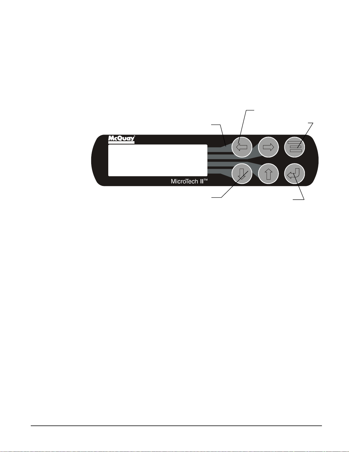
Keypad/Display
A 4-line by 20-character/line liquid crystal display and 6-key keypad is mounted on each
controller. Its layout is shown below.
Figure 6, Keypad and Display in MENU Mode
Air Condi ti oni ng
Key to Screen Pathway
<
ALARM
<
VIEW
<
Arrow Keys
SET
"Enter" Key and Green
Comp. Run Light
Red Alarm Light
Menu Key
The four arrow keys (UP, DOWN, LEFT, RIGHT) have three modes of use.
1. Scroll between data screens as indicated by the arrows (default mode).
2. Select a specific data screen in a hierarchical fashion using dynamic labels on the right
side of the display (this mode is entered by pressing the MENU key).
3. Change field values in edit mode according to the following table:
LEFT Default
RIGHT Cancel
UP Increment
DOWN Decrement
These four edit functions are indicated by one-character abbreviations on the right side of
the display (this mode is entered by pressing the ENTER key).
OM WGS-1 WGS 130A to 190A 15
Page 16

Sequence of Operation
Compressor Heaters
With the control power on, 120V power is applied through the control circuit Fuse FU7 to
the compressor oil separator heater (HTR-OIL SEP).
Startup/Compressor Staging
During Cool Mode the following must be true to start a circuit operating. The evaporator
and condenser pump (WGS-AW only) outputs must be energized and flow must be
established for a period of time defined by the evaporator recirculate setpoint. Established
flow will be detected by evaporator and condenser water flow switches. The water
temperature leaving the evaporator must be greater than the Active Leaving Water
Temperature setpoint, plus the Startup Delta-T, before a circuit will start. The first circuit
to start is determined by sequence number. The lowest sequence numbered circuit will start
first. If all sequence numbers are the same (default), then the circuit with the fewest
number of starts will start first. During operation, the slide valves for loading and
unloading will be pulsed until the active leaving water temperature setpoint is maintained.
The second circuit start will occur once the first circuit has loaded to 75% slide capacity or
is in Capacity Limit and the water temperature leaving the evaporator is greater than the
active leaving water temperature Setpoint plus Stage Delta-T. The circuits will load or
unload simultaneously through a continuous capacity control to maintain the evaporator
leaving water temperature. If all sequence numbers are the same, the circuit with the most
run hours will be shut down first. The circuit with the most run hours will stop when the
water temperature leaving the evaporator is less than the Active Leaving Water
Temperature Setpoint minus Stage Delta-T. The last remaining circuit will shut down
when the water temperature leaving the evaporator is lower than the Active Leaving Water
Temperature Setpoint minus the Stop Delta-T.
Automatic Pumpdown
The Model WGS chiller has two separate refrigerant circuits so the refrigerant charge is
stored in the condenser when the circuit is off. Pumpdown to the condenser helps keep
refrigerant from migrating to the compressor. It also helps establish a pressure differential
on start for oil flow. In a normal shutdown, each circuit will close its expansion valve,
causing the evaporator pressure to reach a low-pressure setpoint. Once this setpoint is
reached, or a specified amount of time has elapsed, the running circuit will be shut down.
Chilled Water and Condenser Water Pumps
The chiller’s MicroTech II controller has a total of four pump outputs, two for the
evaporator and two for the condenser (WGS-AW only). There is a manual setting in the
software for the user to select either pump output 1 or 2. It is recommended that the
chiller’s outputs control the water pumps, as this will offer the most protection for the unit.
Cooling Tower Control
The MicroTech II controller can control the cooling tower fans and/or a tower bypass valve.
This provides a simple and direct method to control the unit’s discharge pressure.
Programming directions and the sequence of operation can be found on page 44. Some
means of discharge pressure control is recommended and must be installed if the entering
condenser water temperature to the condenser can fall below 60°F.
Condenser Fan Control
The MicroTech II controller can be programmed to cycle air-cooled condenser fans on and
off based on the discharge pressure. Details are on page 61.
16 WGS 130A to 190A OM WGS
Page 17
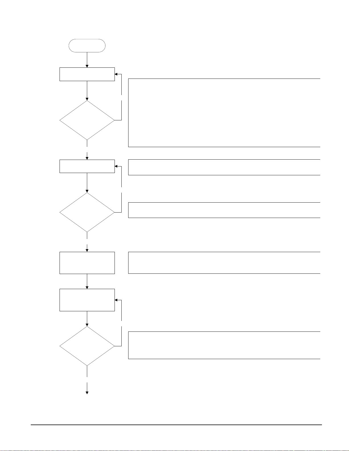
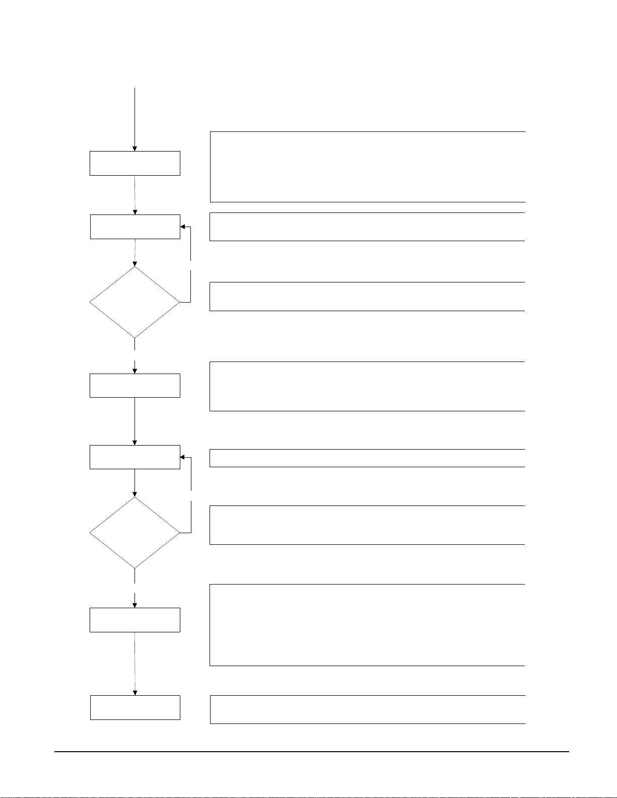
Unit Controller Sequence of Operation
Unit power up
Unit in Off state
The chiller may be disabled via the unit switch, the remote switch, the keypad
enable setting, or the BAS network. In addition, the chiller will be disabled if both
circuits are disabled, either because of an alarm or the circuit pumpdown switch on
No
each circuit, or if there is a unit alarm. If the chiller is disabled, the unit status
display will reflect this and also show why it is disabled.
Is unit enabled?
Yes
Evaporator pump output on
Is flow present?
Yes
Wait for chilled water loop to
recirculate.
If the unit switch is off, the unit status will be
disabled due to network command, the unit status will be
the remote switch is open, the unit status will be
alarm is active, the unit status will be
are enabled, the unit status will be
Off:All Cir Dis abl e d
Off:Unit Switch
Off:Remote Switch
Off:Unit Alarm
. If the chiller is
Off:BAS Disa bl e
. When a unit
. In cases where no circuits
.
If the chiller is enabled, then the unit will be in the Auto state and the evaporator
water pump output will be activated.
No
The chiller will then wait for the flow switch to close, during which time the unit
status will be
Auto:Wait for flow
.
After establishing flow, the chiller will wait some time to allow the chilled water loop
to recirculate for an accurate reading of the leaving water temperature. The unit
status during this time is
Auto:Evap Recirc
.
. When
Keep evaporator pump
output on while unit is
enabled.
No
The chiller is now ready to start if enough load is present. If the LWT is not high
Is there enough load to
start chiller?
Yes
enough to start, the unit status will be
If the LWT is high enough to start, the unit status will be
Auto:Wait Evap Flow
Auto
.
.
OM WGS-1 WGS 130A to 190A 17
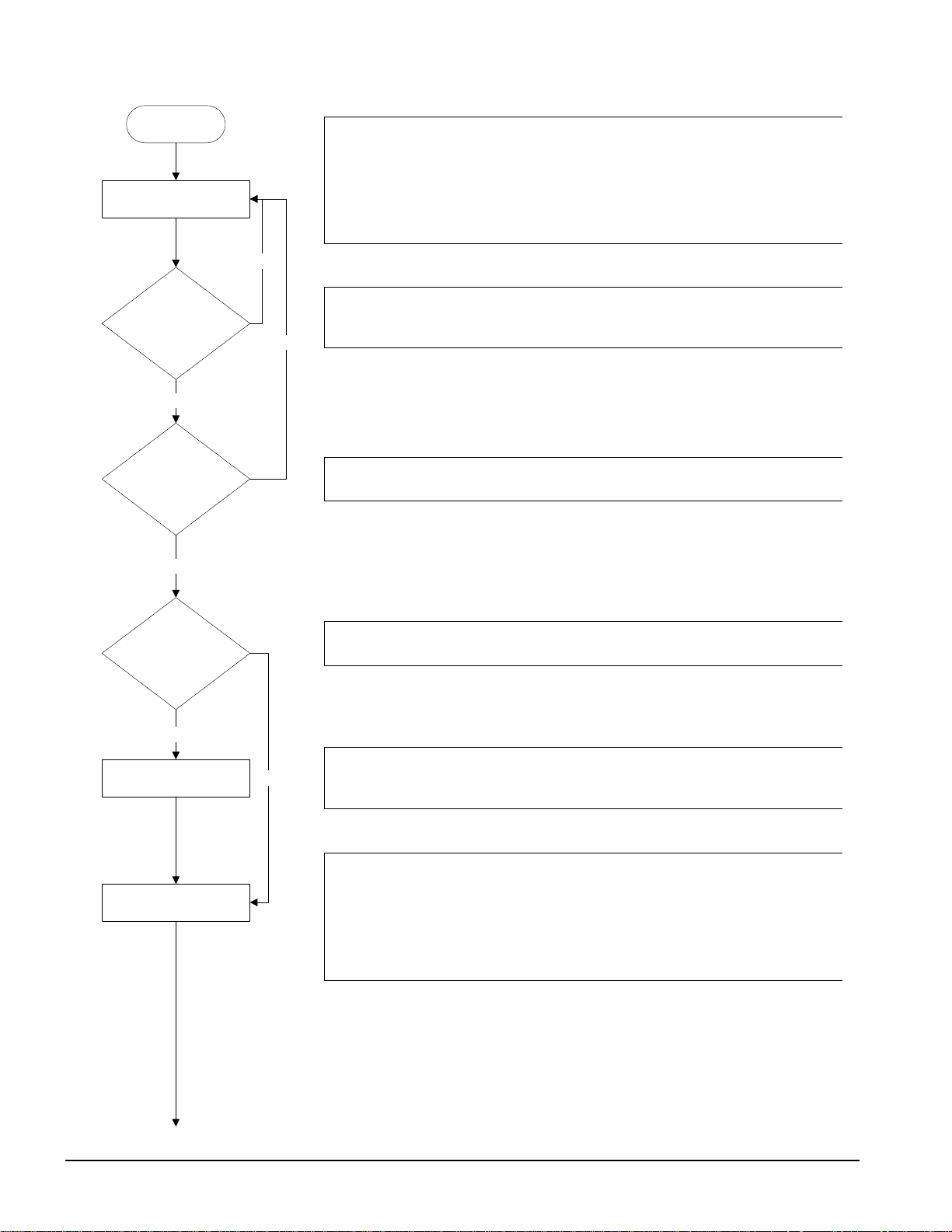
Page 18
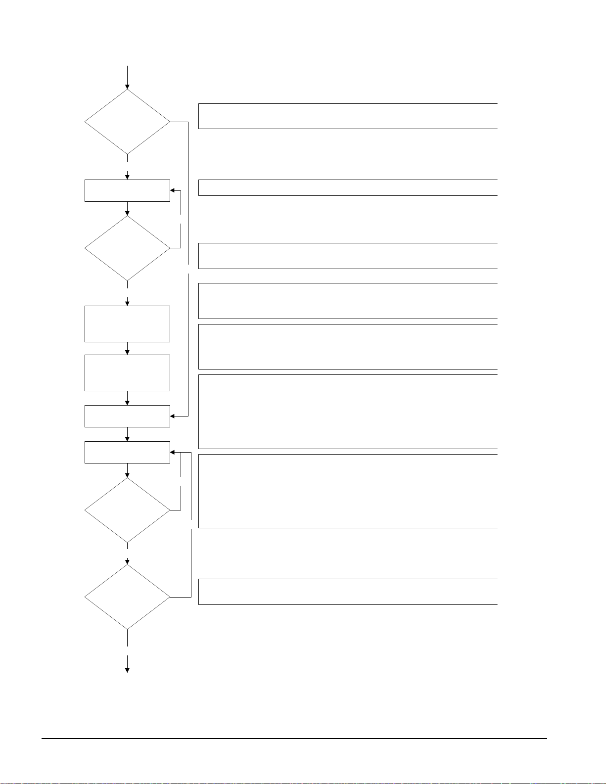
Is unit watercooled?
Yes
If the unit is configured as watercooled, the condenser pump will need to be started.
Otherwise, the unit can start the first circuit at this point.
Condenser pump output on
Is flow present?
Yes
Wait for condenser water
loop to recirculate.
Keep condenser pump
output on while u n it is
enabled and load is present.
Start first circuit.
Load/unload as needed to
satisfy load.
Is more capacity
needed to satisfy load?
If load is present, the condenser water pump output will be activated.
No
The chiller will then wait for the condenser flow switch to close, during which time
the unit status will be
No
Auto:Wait Cond Flow
.
After establishing condenser flow, the chiller will wait some time to allow the
condenser water loop to recirculate and guarantee consistent flow. The unit status
during this time is
Auto:Cond Recirc
.
Once the condenser flow has been present for enough time, the unit status will
become
Auto
. The tower control logic will start working to control the condenser
water temperature, using outputs from the unit controller to control tower fans,
bypass valves, and vfd's as determined by the tower set points.
The first circuit to start is generally the one with the least number of starts, or circuit
one if there is a tie. This circuit will go through its start sequence at this point.
A number of fans may be started with the compressor based on the OAT. Fan
stages will be added/removed as needed to control condenser pressure. The EXV
will begin controlling at this point as well. The compressor cannot start loading until
it has at least 22
o
discharge superheat for more than 30 seconds.
The first circuit will load and unload as needed in an attempt to satisfy the load. It
will eventually get to a point where it is considered to be at full load. A circuit is at
No
full load when it reaches 75% slide target, it reaches the max slide target setting, or
it encounters a problem and is running in an inhibited state.
If a single circuit is not enough to satisfy the load, the second circuit will need to be
started.
No
Yes
Has the stage up time
delay expired?
Yes
A minimum time must pass between the start of the first circuit and the second
circuit.
18 WGS 130A to 190A OM WGS
Page 19
The second circuit will go through its start sequence at this point.
Start second circuit.
Load/unload as needed to
satisfy load.
Can one circuit handle
the load?
Yes
Shut down one circuit.
Load/unload as needed to
satisfy load.
A number of fans may be started with the compressor based on the OAT. Fan
stages will be added/removed as needed to control condenser pressure. The EXV
will begin controlling at this point as well. The compressor cannot start loading until
it has at least 22
o
discharge superheat for more than 30 seconds.
Both circuits will now load/unload as needed to satisfy the load. In addition, they will
load balance so that both circuits are providing nearly equal capacity.
No
As the load drops off, the circuits will unload accordingly. If the LWT gets low
enough, or both circuits unload enough, one circuit can shut off.
The first circuit to shut off is generally the one with the most run hours. The circuit
will do a pumpdown by closing the EXV and continuing to run the compressor until it
reaches the pumpdown pressure or exceeds the pumpdown time limit. Then, the
compressor and all fans will be turned off.
The single running circuit will load/unload as needed to satisfy the load.
No
With one circuit running, the load may drop off to the point where even minimum
Is load satisfied?
Yes
unit capacity is too much. The load has been satisfied when the LWT drops below
the shutdown point. At this time the only running circuit can shut down.
The last circuit running now shuts down. The circuit will do a pumpdown by closing
the EXV and continuing to run the compressor until it reaches the pumpdown
Shut down last circuit.
pressure or exceeds the pumpdown time limit. Then, the compressor and all fans
will be turned off.
The unit should be ready to start again when the LWT gets high enough. The unit
Turn off condenser pump
and tower control.
status at this time will be
Auto:Wait for load
The condenser pump and tower control outputs are turned off until the LWT is high
enough to start again.
.
OM WGS-1 WGS 130A to 190A 19
Page 20
Circuit Controller Sequence of Operation
Unit power up
Circuit is in Off state
Next on?
Yes
Stage up now?
Yes
No
No
When the circuit is in the Off state the EXV is closed, compressor is off, and all fans
are off. The oil heater will be on at this time as long as oil is detected in the
separator.
If the compressor is ready to start when needed, the circuit status will be
Off:Ready
be
. When the circuit switch is off, the circuit cannot start and the status will
Off:Pumpdown Switch
.
If this compressor has the least starts, the other compressor is disabled for some
reason, or the other compressor is already running, then this compressor will be
designated as the next one on.
If there is a need for more cooling capacity , the compressor designated as next on
can start.
Is unit watercooled?
Yes
Preopen EXV
Start Compressor
No
If the unit is configured as watercooled, then the EXV preopen process must be
performed. Otherwise, this is skipped and the compressor can be sta rted.
At this point, the EXV will perform a preopen. While the compressor is off, the EXV
is opened for a period of time to prime the evapora tor an d avoid low pressure at
startup. The circuit status will display
EXV Preopen
.
When the compressor starts, the EXV will open (if not already open) and hold at
3000 steps for 15 seconds.
If the unit is aircooled, depending on the OAT, a number of fans may be started with
the compressor to keep condenser pressure from climbing too fast.
The circuit status will normally be
Run: Disc SH Low
after the compressor starts.
20 WGS 130A to 190A OM WGS
Page 21

Run Compressor
Next off?
Yes
Stage down now?
Yes
When in the Run state, the compressor will load/unload as needed to satisfy the
load. The compressor will also load/unload to load balance with the other
compressor if it is running and not in a limited condition. However, it cannot load up
until the discharge superheat has been over 22 F for at least 30 seconds. After this,
the circuit status will be
Run:Normal
.
The EXV will operate in either Pressure Control or Superheat Control. In Pressure
Control, the evaporator pressure is controlled to a target pressure, which is adjusted
based on LWT and discharge superheat. In Superheat Control, the suction
No
superheat is controlled to a target that varies with discharge superheat.
If unit is aircooled, fans will be staged on and off to control the condenser pressure.
The condenser pressure is controlled to a target that is based on evaporator
pressure, with the target getting higher as the evaporator pressure gets higher.
No
If this compressor has the most run hours or the other compressor is already off,
then this compressor will be designated as the next one off.
If less cooling capacity is needed, the compressor designated as next off can shut
down. This condition may arise when either the LWT has dropped far enough below
the active set point or both circuits are running at a low capacity.
When the circuit does a normal shutdown, a pumpdown is performed. The EXV is
closed while the compressor continues to run. As soon as the pumpdown is
initiated, the compressor is unloaded to the minimum. The condenser fans
continue to control normally during this process. The circuit status during this time
Run:Pumpdown
is
.
Pumpdown circuit
After the evaporator pressure drops below the pumpdown pressure or enough time
has passed, the compressor and fans are shut off to end the pumpdown process.
The circuit status will normally be
Off:Cycle Timers
at this time.
OM WGS-1 WGS 130A to 190A 21
Page 22
Start-Up and Shutdown
Pre Start-up
1. Flush and clean the chilled-water system. Proper water treatment is required to prevent
corrosion and organic growth.
Failure to flush and clean system and provide water treatment can damage the unit.
2. With the main disconnect open, check all electrical connections in control panel and
starter to be sure they are tight and provide good electrical contact. Connections are
tightened at the factory, but can loosen enough in shipment to cause a malfunction.
Lock and tag out all power sources when checking connections. Electrical shock can
3. Check and inspect all water piping. Make sure flow direction is correct and that piping
is made to the correct connection on evaporator and condenser.
4. Check that refrigerant piping on remote condensers is connected to the correct circuits
and not crossed and has been properly leak tested and evacuated.
5. Open all water flow valves to the condenser and evaporator.
6. Flush the cooling tower and system piping to be sure the system is clean. Start
evaporator pump and manually start condenser pump and cooling tower. Check all
piping for leaks. Vent the air from the evaporator and condenser water circuit, as well
as from the entire water system. The cooler circuit should contain clean, treated, noncorrosive water.
7. Check to see that the evaporator water temperature sensor is securely installed.
8. Make sure the unit control switch S1 is open OFF and the circuit switches CS1 and
CS2 are open. Place the main power disconnect switch to ON. This will energize the
compressor sump heaters. Wait a minimum of 12 hours before starting the unit.
9. Measure the water pressure drop across the evaporator and condenser, and check that
water flow is correct (on pages 25 and 26) per the design flow rates.
10. Check the actual line voltage to the unit to make sure it is the same as called for on the
compressor nameplate, within + 10%, and that phase voltage unbalance does not
exceed 2%. Verify that adequate power supply and capacity is available to handle load.
11. Make sure all wiring and fuses are of the proper size. Also make sure that all interlock
wiring is completed per McQuay diagrams.
12. Verify that all mechanical and electrical inspections by code authorities have been
completed.
13. Make sure all auxiliary load and control equipment is operative and that an adequate
cooling load is available for initial start-up.
CAUTION
CAUTION
cause severe personal injury or death.
Start-up
1. Open the compressor discharge shutoff valves until backseated. Replace valve seal
caps.
2. Open the two manual liquid line shutoff valves (king valves).
22 WGS 130A to 190A OM WGS
Page 23

3. Verify that the compressor sump heaters have operated for at least 12 hours prior to
start-up. Crankcase should be warm to the touch.
4. Check that the MicroTech II controller is set to the desired chilled water temperature.
5. Start the system auxiliary equipment for the installation by turning on the time clock,
ambient thermostat and/or remote on/off switch and water pumps.
6. Switch on the unit circuit breakers.
7. Set circuit switches CS1 and CS2 to ON for normal operation.
8. Start the system by setting the unit system switch S1 to ON.
9. After running the unit for a short time, check the oil level in each compressor, rotation
of condenser fans (if any), and check for flashing in the refrigerant sight glass.
Weekend or Temporary Shutdown
Move circuit switches CS1 and CS2 to the OFF pumpdown position. After the compressors
have shut off, turn off the chilled water pump if not on automatic control from the chiller
controller or building automation system (BAS). With the unit in this condition, it will not
restart until these switches are turned back on.
Leave on the power to the unit (disconnect closed) so that the sump heaters will remain
energized.
Start-up after Temporary Shutdown
1. Start the water pumps.
2. Check compressor sump heaters. Compressors should be warm to the touch.
3. With the unit switch S1 in the ON position, move the circuit switches CS1 and CS2 to
the ON position.
4. Observe the unit operation for a short time, noting unusual sounds or possible cycling
of compressors.
Extended Shutdown
1. Close the manual liquid line shutoff valves.
2. After the compressors have shut down, turn off the water pumps.
3. Turn off all power to the unit.
4. Move the unit control switch S1 to the OFF position.
5. Close the discharge shutoff valves.
6. Tag all opened disconnect switches to warn against start-up before opening the
compressor suction and discharge valves.
7. Drain all water from the unit evaporator, condenser and chilled water piping if the unit
is to be shut down during the winter and exposed to below-freezing temperatures. To
help prevent excessive corrosion, do not leave the vessels or piping open to the
atmosphere over the shutdown period.
Start-up after Extended Shutdown
1. Inspect all equipment to see that it is in satisfactory operating condition.
2. Remove all debris that has collected on the surface of the condenser coils (remote
condenser models) or check the cooling tower, if present.
OM WGS-1 WGS 130A to 190A 23
Page 24
3. Open the compressor discharge valves until backseated. Always replace valve seal
caps.
4. Open the manual liquid line shutoff valves.
5. Check circuit breakers. They must be in the OFF position.
6. Check to see that the circuit switches CS1 and CS2 and the unit control switch S1 are in
the OFF position.
7. Close the main power disconnect switch. The circuit disconnects switches should be
off.
8. Allow the sump heaters to operate for at least 12 hours prior to start-up.
9. Start the chilled water pump and purge the water piping as well as the evaporator in the
unit.
10. Start the system auxiliary equipment for the installation by turning on the time clock,
ambient thermostat and/or remote on/off switch.
11. Check that the MicroTech II controller is set to the desired chilled water temperature.
12. Switch the unit circuit breakers to ON.
13. Start the system by setting the system switch S1 and the circuit switches to ON.
CAUTION
Most relays and terminals in the control center are powered when S1 is
closed and the control circuit disconnect i s on. Therefore, do not close S1
until ready for start-up or serious equipment damage can occur.
14. After running the unit for a short time, check the oil level in the compressor oil sight
glass and check the liquid line sight glass for bubbles.
24 WGS 130A to 190A OM WGS
Page 25
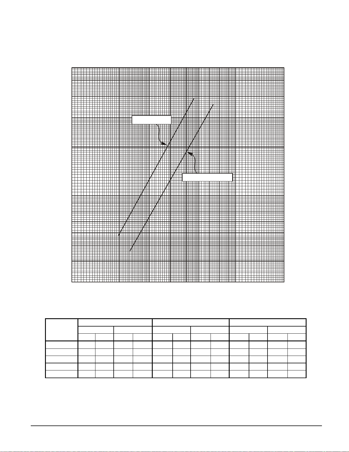
Figure 7, Evaporator Pressure Drop WGS 130 – WGS 190
(
)
Flow Rate (L/s)
6131925323844505763
60
126
180
50
40
30
20
10
9
8
Pressure Drop (ft of water)
7
6
5
WGS 130, 140
WGS 160, 170, 190
150
120
90
60
30
27
24
21
18
15
Pressure Drop
kPa
4
3
100 200 300 400 500 600 700
800
900
1000
12
9
2000
Flow Rate (GPM)
Minimum Flow Nominal Flow Maximum Flow
WGS Model
130AW/AA
140AW/AA
160AW/AA
170AW/AA
190AW/AA
Note: Minimum, nominal, an d maximum flows are at a 16°F, 10°F, and 6°F chilled water temperature range respectively and at ARI tons.
Flow Rate Pressure Drop Flow Rate Pressure Drop Flow Rate Pressure Drop
gpm L/s Ft. kPa gpm L/s Ft. kPa gpm L/s Ft. kPa
195 12.3 5.8 17.4 312 19.7 13.5 40.4 520 32.9 33.9 101.1
211 13.4 6.7 20.0 338 21.4 15.6 46.6 563 35.6 39.0 116.5
235 14.9 4.6 13.8 376 23.8 10.8 32.3 627 39.7 27.3 81.6
254 16.1 5.3 15.9 407 25.8 12.5 37.3 678 42.9 31.6 94.2
273 17.3 6.1 18.1 437 27.7 14.2 42.5 728 46.1 35.9 107.2
OM WGS-1 WGS 130A to 190A 25
Page 26
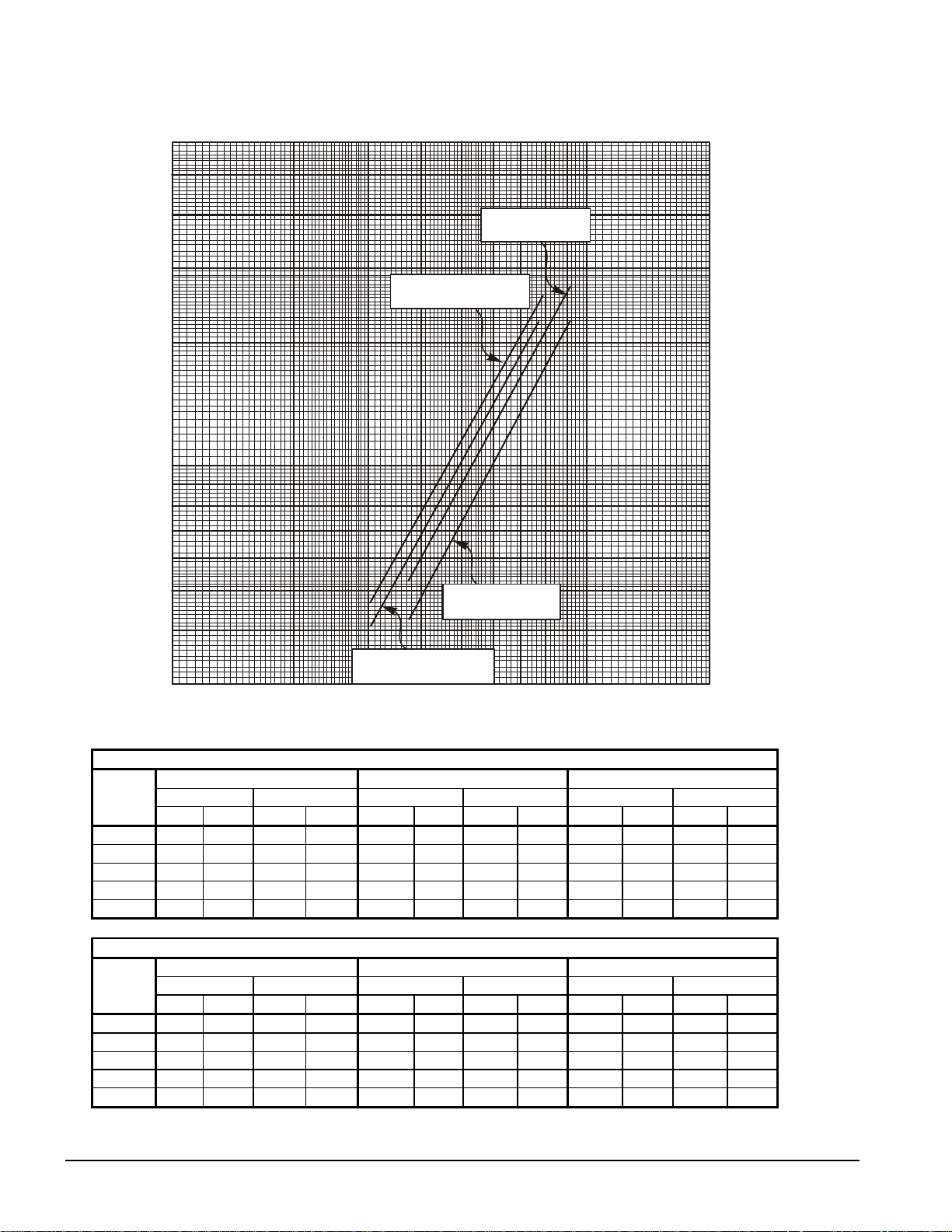
Figure 8, Condenser Pressure Drop WGS 130 – WGS 190
P
D
Flow Rate (L/s)
6131925323844505763
60
126
180
rop (ft of water)
ressure
WGS
Model
130AW
140AW
160AW
170AW
190AW
WGS
Model
130AW
140AW
160AW
170AW
190AW
50
40
WGS 170, 190
150
120
with Manifold
30
90
WGS 130, 140, 160
with Manifold
20
10
9
8
7
6
5
WGS 170, 190
60
30
27
24
21
18
15
without Manifold
4
12
WGS 130, 140, 160
3
100 200 300 400 500 600 700
without Manifold
800
900
1000
2000
Flow Rate (GPM)
Pressure Drop Without Optional Condenser Manifold
Minimum Flow Nominal Flow Maximum Flow
Flow Rate Pressure Drop Flow Rate Pressure Drop Flow Rate Pressure Drop
gpm L/s Ft. kPa gpm L/s Ft. kPa gpm L/s Ft. kPa
304 19.2 4.1 12.2 390 24.7 6.5 19.3 650 41.1 16.0 47.9
304 19.2 4.1 12.2 422 26.7 7.4 22.2 704 44.5 18.5 55.1
304 19.2 4.1 12.2 470 29.8 9.0 26.9 784 49.6 22.4 66.8
372 23.5 4.3 12.8 509 32.2 7.9 23.7 848 53.7 19.8 59.1
372 23.5 4.3 12.8 546 34.6 9.0 26.9 911 57.6 22.5 67.1
Pressure Drop With Optional Condenser Manifold
Minimum Flow Nominal Flow Maximum Flow
Flow Rate Pressure Drop Flow Rate Pressure Drop Flow Rate Pressure Drop
gpm L/s Ft. kPa gpm L/s Ft. kPa gpm L/s Ft. kPa
304 19.2 4.7 14.0 390 24.7 7.4 22.0 650 41.1 18.5 55.1
304 19.2 4.7 14.0 422 26.7 8.5 25.3 704 44.5 21.3 63.5
304 19.2 4.7 14.0 470 29.8 10.3 30.7 784 49.6 25.8 77.1
372 23.5 5.3 15.8 509 32.2 9.4 28.1 848 53.7 23.8 71.1
372 23.5 5.3 15.8 546 34.6 10.7 32.0 911 57.6 27.1 80.9
Pressure Drop (kPa)
9
26 WGS 130A to 190A OM WGS
Page 27
Unit Controller
Unit Inputs/Outputs
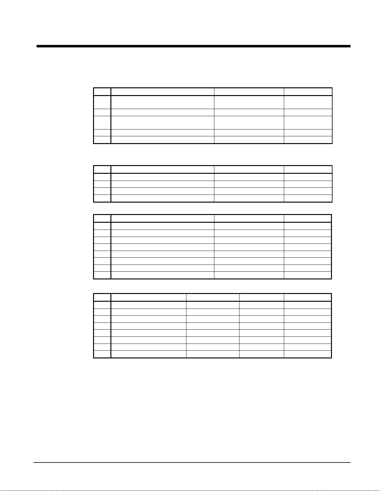
Table 1, Analog Inputs
# Description Signal Source Range
1
2
3
4
5
C1 = Refrigerant Circuit #1, C2 = Refrigerant Circuit #2, UT = Unit
Table 2, Analog Outputs
# Description Output Signal Range
1
2
3
4
Table 3, Digital Inputs
# Description Signal Signal
1
2
3
4
5
6
7
8
Condenser EWT or Outdoor
Ambient Temp.
Demand Limit 4-20 mA Current 0 to 100% limit
Chilled Water Reset 4-20 mA Current
Leaving Evaporator Water Temp. Thermister (10k@25°C) -58 to 212°F
Entering Evaporator Water Temp. Thermister (10k@25°C) -58 to 212°F
Cooling Tower Bypass Valve Position 0 to 10 VDC 0 to 100%
Cooling Tower VFD Speed 0 to 10 VDC 0 to 100%
Open
Open
Unit Switch 0 VAC (Stop) 24 VAC (On)
Remote Switch 0 VAC (Stop) 24 VAC (Start)
Evaporator Water Flow Switch 0 VAC (No Flow) 24 VAC (Flow)
Mode Switch 0 VAC (Cool) 24 VAC (Ice)
Condenser Water Flow Switch 0 VAC (No Flow) 24 VAC (Flow)
Open
Open
Open
Thermister (10k@25°C) -58 to 212°F
0 to 10 degrees
60°F max.
Table 4, Digital Outputs
# Description Load Output OFF Output ON
Evaporator Water Pump 1 Pump Contactor Pump OFF Pump ON
1
Evaporator Water Pump 2 Pump Contactor Pump OFF Pump ON
2
Condenser Water Pump 1 Pump Contactor Pump OFF Pump ON
3
Condenser Water Pump 2 Pump Contactor Pump OFF Pump ON
4
Tower Fan 1 Fan Contactor Fan OFF Fan ON
5
Tower Fan 2 Fan Contactor Fan OFF Fan ON
6
Remote Run Status All Circuits Off Any Circuit On
7
Alarm Remote Alarm No alarm Stop alarm
8
Unit Setpoints
The following parameters are retained during power off, are factory set to the Default
value, and can be adjusted to any value in the Range column.
The Type defines whether the setpoint is part of a coordinated set of duplicate setpoints in
different controllers. Types are as follows:
N = Normal setpoint – Not copied from, or copied to, any other controller
M = Master setpoint – Setpoint is copied to all controllers in the “Sent To” column
The PW (password) column indicates the password level that must be active in order to
change the setpoint. Passwords are as follows:
O = Operator [0100] M = Manager (8745)
OM WGS-1 WGS 130A to 190A 27
Page 28

Toggle: Setpoints that have two choices, such as ON and OFF are toggled between the two
settings using the Up or Down keys on the controller.
NOTE: in some software versions the terms “inhibit” and “hold” are used interchangeably.
Table 5, Unit Controller Setpoints
Description Default Range Type PW
Unit
Unit Enable OFF OFF, ON N O
Unit Mode Cool Cool, Ice, Test M O
Control source Switches Switches, Keypad, Network N O
Available Modes Cool
Cool LWT
Ice LWT
Start Delta T
Stop Delta T
Stage Up Delta T
Stage Down Delta T
Max Pulldown
Evap Recirc Timer 30 0 to 300 seconds N M
Evap Pump Select #1 Only #1 Only, #2 Only, Auto N M
Water-cooled Yes No, Yes N M
Cond Recirc Timer (watercooled only)
Cond Pump Select (watercooled only)
LWT Reset Type NONE NONE, RETURN, 4-20mA, OAT N M
Max Reset
Start Reset Delta T
Soft Load Off Off, On N M
Begin Capacity Limit 40% 20-100% N M
Soft Load Ramp 20 min 1-60 minutes N M
Demand Limit Off Off, On N M
Low OAT Operation
(air-cooled only)
Low Ambient Lockout (air
cooled only)
Ice Time Delay 12 1-23 hours N M
Clear Ice Timer No No,Yes N M
Evap LWT sensor off set 0 -5.0 to 5.0 deg N T
Evap EWT sensor of fset 0 -5.0 to 5.0 deg N T
Cond EWT/OAT sensor offset 0 -5.0 to 5.0 deg N T
Cond LWT sensor off set 0 -5.0 to 5.0 deg N T
Units
BAS Protocol Modbus BACnet, LonWorks, Modbus N M
Ident number 1 0-200 N M
Baud Rate 19200 1200,2400,4800,9600,19200 N M
Compressors
Sequence # Cir 1 1 1-2 M M
Sequence # Cir 2 1 1-2 M M
Start-start timer 20 min 15-60 minutes M M
Stop-start tim er 5 min 3-20 minutes M M
Pumpdown Pressure 25 psi 10 to 40 psi M T
Pumpdown Time Limit 120 sec 0 to 180 s ec M T
Light Load Stg Dn Point 25% 20 to 50% M T
Stage Up Delay 5 min 0 to 60 min M T
44 °F 30(40) to 60 °F
25 °F 20 to 38°F
10 °F 0 to 10 °F
1.5 °F 0 to 3 °F
2 °F 0 to 3 °F
1 °F 0 to 3 °F
5 °F/min 0.5-5.0 °F /min
30 0 to 300 seconds N M
#1 Only #1 Only, #2 Only, A uto N M
0 °F 0 to 20 °F
10 °F 0 to 20 °F
No No, Yes N M
55 °F 0(35) to 70 °F
°F/psi °F/psi, °C/kPa
Continued next page
Cool, Cool w/Glycol, Cool/Ice
w/Glycol, ICE w/Glycol, TEST
N T
N O
N O
M O
M O
M O
M O
M M
N M
N M
N M
N M
28 WGS 130A to 190A OM WGS
Page 29

Description Default Range Type PW
Alarms
Low Evap Pressure-Unload 28 psi [0,26] to 45 psi M T
Low Evap Pressure-Hold 30 psi [ 0,28] to 45 psi M T
Low Oil Level Delay 120 s ec 10-180 sec M T
High Oil Press Diff Delay 15 sec 0-60 sec M T
High Discharge Temperature
High Lift Pressure Delay 5 sec 0 to 30 sec M T
Evaporator Water Freeze
Evaporator Flow Proof 3 sec 3 to 10 sec N T
Low OAT Start Timer (air
cooled only)
Condenser Water Freeze
(water cooled only)
Condenser Flow Proof (water
cooled only)
Cooling Tower(available for Water cooled only)
Tower Control None None, Temperature N M
Tower Stages 2 0 to 2 N M
Stage #1 On
Stage #2 On
Stage Differential
Stage Up Time 2 min 1 to 60 min N M
Stage Down Time 5 min 1 to 60 min N M
Stage Fan Down @ 20% 0 to 100% N M
Stage Fan Up @ 80% 0 to 100% N M
Valve/VFD Control None
Valve Type NC to tower NC, NO N M
Valve Setpoint
Valve Deadband
Minimum Start P osition 0% 0 to 100% N M
Minimum Position @
Maximum Start Position 100% 0 to 100% N M
Maximum Position @
Valve Control Range (Min) 10% 0 to 100% N M
Valve Control Range(Max) 90% 0 to 100% N M
Error Gain 25 10 to 99 N M
Slope Gain 25 10 to 99 N M
200 °F
36 °F 15(36) to 42 °F
60 sec 20 to 90 sec M T
38 °F 34 to 42 °F
3 sec 3 to 10 sec N T
70 °F 40 to 120 °F
75 °F 40 to 120 °F
3.0 °F 1.0 to 10.0 °F
None, Valve Setpoint, Valve S t age,
VFD Stage, Valve SP/V FD Stage
65 °F 60 to 120 °F
2.0 °F 1.0 to 10.0 °F
60 °F 0 to 100 °F
90 °F 0 to 100 °F
150 to 200 F M T
N T
N T
N M
N M
N M
N M
N M
N M
N M
N M
Auto A dj usted Ranges
The following settings have different ranges of adjustment based on other settings.
Table 6, Cool LWT
Mode Range
Unit Mode = Cool 40 to 60oF
Unit Mode = Cool w/Glycol, Ice w/ Glycol 20 to 60oF
Table 7, Evaporator Water Freeze
Mode Range
Unit Mode = Cool 34 to 42oF
Unit Mode = Cool w/Glycol, Ice w/ Glycol 15 to 42oF
OM WGS-1 WGS 130A to 190A 29
Page 30

Table 8, Low Evaporator Pressure Inhibit
Unit Mode = Cool 30 to 45 Psig
Unit Mode = Cool w/Glycol, Ice w/ Glycol 15 to 45 Psig
Table 9, Low Evaporator Pressure Unload
Unit Mode = Cool 28 to 45 Psig
Unit Mode = Cool w/Glycol, Ice w/ Glycol 15 to 45 Psig
Circuit Controller
Circuit Inputs and Outputs
Table 10, Analog Inputs
# Description Signal Source Range
1 Evaporat or Pressure 0.1 to 0.9 VDC
2 Condens er P ressure 0.1 to 0.9 VDC
3 Open
4 Suction Temperature NTC Thermister (10k@25°C) -58 to 212°F
5 Dis charge Temperature NTC Thermister (10k @25° C) -58 to 212°F
6 Open
7 Sl i de Load Indicator 4 to 20 mA
8 Condenser LWT (circuit 1, water c ool ed onl y) NTC Thermister (10k@25°C) -58 to 212°F
Mode Range
Mode Range
0 to 132 psi
3.6to 410 psi
0 to 100%
Table 11, Analog Outputs
# Description Output Signal Range
1 Fan VF D (ai r cooled only) 0 to 10 VDC 0 to 100% (1000 steps resol ution)
2 Open
3 EXV Driver 0 to 10 VDC 0 to 6386 steps (1000 steps res ol ution)
4 Open
Table 12, Digital Inputs
# Description Signal Signal
1 Circuit Switch 0 VAC (Off) 24 VAC (Auto)
2 Open
3 Open
4 VFD Fault 0 VAC (Fault) 24 VAC (No Fault)
5 Oil Differential Pressure Switch 0 VAC (Fault) 24 VAC (No Fault)
6 Mechanical High Pressure Switc h 0 VAC (Fault) 24 VAC (No Faul t )
7 Open
8 Open
9 Oil Level Sensor 0 VAC (Fault) 24 VAC (No Fault)
10-14 Open
The status of digital inputs may be viewed on Circuit Status screen 5, on the circuit
controllers only.
30 WGS 130A to 190A OM WGS
Page 31

Table 13, Digital Outputs
# Description Output OFF Output ON
1 Fan 1 Contactor (air cooled only) Fan off Fan on
2 Fan 2 Contactor (air cooled only) Fan off Fan on
3 Fan 3 Contactor (air cooled only) Fan off Fan on
4 Fan 4 Contactor (air cooled only) Fan off Fan on
5 Fan 5 Contactor (air cooled only) Fan off Fan on
6 Fan 6 Contactor (air cooled only) Fan off Fan on
7 Load/Unl oad Pulse Hold load slide Move load slide
8 Load/Unload Select Unload Load
9 Compressor SSS Contact Compressor off Compressor on
10 Open
11 Oil Heater Heater off Heater on
12 Interstage Injection (future us e) Injection off Injection on
13 EXV Close Signal
EXV follows
0 –10 VDC
EXV closed, ignores 0 –
10 VDC
Circuit Setpoint Table
The following parameters must be remembered during power off, are factory set to the
Default value, and can be adjusted to any value in the Range column.
The PW (password) column indicates the password that must be active in order to change
the setpoint. Codes are as follows:
O = Operator (100) M = Manager T = Technician
Table 14, Circuit Setpoints
Description Default Range PW
Compressor
Circuit mode enable Disable, enable, test T
Slide control auto Auto, manual T
Slide target 0 0-100 T
Compressor Size 167 167, 179, 197 T
Clear Cycle Timers No No, Yes T
Maximum Slide Target 100.0 0-100.0% T
Motor FLA See Table 15 1 to 321 amps T
Motor RLA See Table 15 1 to 321 amps T
Ground Fault Enable Disable Disable, Enable T
Ground Fault Trip Level 1 0 to 100% T
EXV
EXV control Auto Auto, manual T
Manual EXV position 0 0-6386 T
Service Pumpdown No No,Yes T
Preopen Timer (water cooled only) 20 20 to 120 seconds T
Sensors (NOTE 1)
Evap pressure offset 0 -10.0 to 10.0 psi T
Cond pressure offset 0 -10.0 to 10.0 psi T
Suction temp offset 0 -5.0 to 5.0 deg T
Discharge temp offs et 0 -5.0 to 5.0 deg T
Slide Minimum Posi t i on Offset 0 -15 to 15% T
Slide Maximum Position Offset 0 -15 to 15% T
Continued next page
OM WGS-1 WGS 130A to 190A 31
Page 32

Description Default Range PW
Fans (available for air-cooled only)
Fan VFD enable On Off, On T
Number of fans 4 4 to 6 T
Saturated Condenser Temp Target Min 90.0 80. 0-110.0
Saturated Condenser Temp Target Max 110.0 90.0-120.0 oF T
Stage 1 On Deadband 8.0 1.0-20.0 oF T
Stage 2 On Deadband 10.0 1.0-20.0 oF T
Stage 3 On Deadband 11.0 1.0-20.0 oF T
Stage 4 On Deadband 12.0 1.0-20.0 oF T
Stage 2 Off Deadband 20.0 1.0-25.0 oF T
Stage 3 Off Deadband 16.0 1.0-25.0 oF T
Stage 4 Off Deadband 11.0 1.0-25.0 oF T
Stage 5 Off Deadband 8.0 1.0-25.0 oF T
VFD Max Speed 100% 90 to 110% T
VFD Min Speed 25% 20 to 60% T
Forced Fantrol 1 2 1 to 4 T
Forced Fantrol 2 3 1 to 4 T
Forced Fantrol 3 4 1 to 4 T
Notes:
1. Offsets are used to fine-tune certain readings generated by sensors. For example, if the controller was
showing a 125 psi value and a calibrated pressure gauge at the same location showed 127 psi, an offset of
+2 psi would be entered and the controller would then read the corrected value of 127 psi.
o
F T
Table 15, RLA/FLA Values
Compressor 575V 460V 380V 230V 208V 400V (50Hz)
197 113 141 178 282 312 141
179 94 122 145 240 267 122
167 85 112 128 210 232 112
All 113 141 178 282 312 141
NOTE: Table values used for circuit controller input.
Alarms, Warnings, Events
Stop Alarms (Shutdown)
Equipment protection alarms trigger a rapid unit or compressor shutdown. The following
tables identify each equipment protection alarm, give the condition that causes the alarm to
occur, and states the action taken because of the alarm. All stop alarms require a manual
reset. These alarms will energize a remote alarm (if the unit is so wired in the field), will
energize a red light behind the left arrow button on the display and will be logged in the
Alarm Log.
Table 16, Unit
Alarm Description Occurs When: Action Taken Reset
No Evaporator
Water Flow
Continued next page
Stop Alarms, Shutdown
Evap Pump State = RUN AND Evap Flow
Digital Input = No Flow for time > Flow Proof
SP, OR Evap Pump State = START AND
Evap Flow Digital Input = No Flow for time >
RLA
FLA
Rapid Stop See Note
Evap Recirc Time SP
32 WGS 130A to 190A OM WGS
Page 33

Alarm Description Occurs When: Action Taken Reset
Cond Pump State = RUN AND Cond Flow
No Condenser
Water Flow
Evaporator Water
Freeze Protect
Leaving Evaporator
Water Temperature
Sensor Fault
Cond EWT/Outside
Air Temperature
Sensor Fault
pLAN Failure
Digital Input = No Flow for time > Flow Proof
SP, OR Cond Pump State = START AND
Cond Flow Digital Input = No Flow for time >
Cond Recirc Time SP
Evap LWT goes below evap freeze protect
setpoint
Sensor shorted or open Rapid Stop Manual
Sensor shorted or open Rapid Stop Manual
No other controllers found on pLAN for 60
seconds
Rapid Stop See Note
Rapid Stop Manual
Rapid Stop Manual
NOTE: Each day (beginning at 12:00 am), two automatic resets (based on the flow switch closing)
are allowed before a manual reset requirement occurs. When an auto-clear occurs, the unit will go to
the Start state and be waiting for flow. When flow is detected, the unit goes through the normal
starting sequence and the flow loss alarm will clear. Flow loss is only triggered when a compressor is
running.
Condenser flow loss is auto-reset, regardless of the number of occurrences. When a flow loss is
detected, the unit goes back to the “Start” state, waiting for flow
Table 17, Circuit Stop Alarms, Shutdown
Alarm Description Occurs When: Action Taken Reset
Low Evaporator
Pressure
High Lift Pressure Cond Sat Temp > Max Sat Cond Value Rapid Stop Manual
Mechanical High
Pressure
Below Minimum Lift
Pressure
High Discharge
Temperature
Low Oil Level
High Oil Pressure
Difference
Starter Fault
Current Overload
Trip
Current Imbalance
Low Motor Current
High Motor
Temperature
Phase Loss
Phase Reversal
Overvoltage
Undervoltage
Continued next page.
Evaporator Press < 5 psi OR [Freezestat
trip AND Compressor State = Run]
Digital Input 6 = Open Rapid Stop Manual
Cond Press < Min Sat Cond Value for time
> Min Lift Delay SP
Temp > High Discharge Temperature SP Rapid Stop Manual
DI9 = Open for Time greater than Low Oil
Level Delay AND the Low Oil Level Event
has occurred in the past hour
Digital Input 5 = Open for time greater than
High Press Diff Delay SP
Starter Status bit 4 set (fault) and Starter
Fault Code =
12,13,40,47,50,51,52,61,71,94,95,96,97,9
8,99
Starter Status bit 4 set (fault) and Starter
Fault Code = 2, 30, or 31
Starter Status bit 4 set (fault) and Starter
Fault Code = 37
Starter Status bit 4 set (fault) and Starter
Fault Code = 39
Starter Status bit 4 set (fault) and Starter
Fault Code = 60
Starter Status bit 4 set (fault) and Starter
Fault Code = 15 or 27
Starter Status bit 4 set (fault) and Starter
Fault Code = 10
Starter Status bit 4 set (fault) and Starter
Fault Code = 24, 25, or 26
Starter Status bit 4 set (fault) and Starter
Fault Code = 21, 22, 23, or 28
Rapid Stop Manual
Pumpdown Manual
Rapid Stop Manual
Rapid Stop Manual
Rapid Stop Manual
Rapid Stop Manual
Rapid Stop Manual
Rapid Stop Manual
Rapid Stop Manual
Rapid Stop Manual
Rapid Stop Manual
Rapid Stop Manual
Rapid Stop Manual
OM WGS-1 WGS 130A to 190A 33
Page 34

Alarm Description Occurs When: Action Taken Reset
Ground Fault
Protection
No Starter Transition
Evaporator Pressure
Sensor Fault
Condenser Pressure
Sensor Fault
Liquid Line Pressure
Sensor Fault
Suction Temperature
Sensor Fault
Discharge
Temperature Sensor
Fault
Liquid Line
Temperature Sensor
Fault
Slide Position
Sensor Fault
Starter Status bit 4 set (fault) and Starter
Fault Code = 38
Starter Status bit 4 set (fault) and Starter
Fault Code = 1 or 48
Sensor shorted or open Rapid Stop Manual
Sensor shorted or open Rapid Stop Manual
Sensor shorted or open Pumpdown Manual
Sensor shorted or open Pumpdown Manual
Sensor shorted or open Pumpdown Manual
Sensor shorted or open Pumpdown Manual
Sensor shorted or open Pumpdown Manual
Rapid Stop Manual
Rapid Stop Manual
Events (Limit)
The following events do not cause a rapid shutdown, but limit chiller operation in some way
as described in the Action Taken column. These events do not trigger a remote alarm signal
or the red Alarm LED on the controller. They appear only in the Event Log menu. They
reset automatically when conditions return to a normal range.
If the chiller fails to make the chilled water setpoint, the Event Log should be checked as a
forced limit on loading, or actual compressor unloading may be occurring.
NOTE: In some software versions the terms “inhibit” and “hold” are used interchangeably.
The following unit events are logged in the event log with a time stamp
Table 18, Unit Events (Limits)
Description Occurs When: Action Taken Reset
Entering Evaporator
Temperature Sensor
Fault
Condenser LWT Sensor
Fault
Sensor is open or shorted
Sensor is open or shorted None Automatic
Cannot use
return water
reset
Automatic
Table 19, Circuit Events (Limits)
Event Description Occurs When: Action Taken Reset
Low Evaporator
Pressure – Hold
Low Evaporator
Pressure – Unload
High Lift Pressure Hold
High Lift Pressure Unload
Subcooling Low
Continued on next page.
Pressure < Low Evap Pressure –
Hold SP
Pressure < Low Evap Pressure –
Unload SP
Pressure > High Sat Cond -
Hold Value
Pressure > High Sat Cond -
Unload Value
Subcool < Low Subcool SP for
longer than 5 minutes
Inhibit loading
Unload
Inhibit loading
Unload
None
Evap Press rises
above (SP + 3psi)
Evap Press rises
above (SP + 5psi)
Cond Press drops
below (Hold Value –
Cond Press drops
below (Unload Value
Subcool > setpoint
or Comp state = off
10
– 10
o
F)
o
F)
34 WGS 130A to 190A OM WGS
Page 35

Event Description Occurs When: Action Taken Reset
Input Open for Time greater than
Oil Level Low
Failed Prepurge
Failed Pumpdown
Condenser Freeze
Protect
Power Loss While
Running
Low Oil Level Delay AND more
than one hour since last
occurrence
Circuit state = prepurge for more
than the Prepurge Time SP
Circuit state = pumpdown for
more than the Pumpdown Time
SP
Cond Sat Refr Temp <
Condenser Freeze SP AND
Cond Pump State = OFF
Note: Water Cooled = Y Only
Circuit controller is powered up
after losing power while
compressor was running
Rapid stop Comp state = off
Open EXV N/A
Stop N/A
Start
condenser
pump
Delay start of
compressor
Cond Sat Refr Temp
> (Condenser
Freeze SP + 2°F)
N/A
Clearing Alarms
Alarms may be cleared at the unit controller if any password level is active. If the user
attempts to clear an alarm while no password is active, then the controller will
automatically go to the ENTER PASSWORD screen. The user can then enter a password
normally, and scroll back to the active alarm column to clear the active alarm(s). The BAS
can clear evaporator flow loss, evaporator water freeze and pLAN failure regardless of
what other alarms are active.
Unit Controller Functions
Calculations
LWT Slope
LWT slope is calculated such that the slope represents the change in LWT over a time
frame of one minute.
Every 12 seconds, the current LWT is subtracted from the value 12 seconds back. This
value is added to a buffer containing values calculated at the last five intervals. The final
result is a slope value that is an average over the past 60 seconds.
Pulldown Rate
The slope value calculated above will be a negative value as the water temperature is
dropping. For use in some control functions, the negative slope is converted to a positive
value by multiplying by –1.
Unit Capacity
Unit capacity is estimated based on the slide target of each running circuit. The capacity of
a running circuit is estimated with this equation:
Circuit capacity = 0.8(slide target) + 20
A circuit that is off is assumed to be at 0% capacity. The unit capacity is then calculated by
this equation:
Unit capacity = (Circuit 1 capacity + Circuit 2 capacity)/2
OM WGS-1 WGS 130A to 190A 35
Page 36

Unit Enable
Enabling and disabling the chiller is controlled by the Unit Enable Setpoint with options of
OFF and ON. Enabling allows the unit to start if there is a call for cooling and also starts
the evaporator pump.
This setpoint (in other words, enabling the unit to run) can be altered by the:
− Unit OFF input (unit On/Off switch)
− a field installed remote stop switch
− a keypad entry
− a BAS request
The Control Source Setpoint determines which sources can change the Unit Enable
Setpoint with options of SWITCHES, KEYPAD or NETWORK.
Changing the Unit Enable Setpoint can be accomplished according to the following table.
NOTE: An “x” indicates that the entry is ignored.
Table 20, Unit Enable Combinations
Unit On/Off
Switch
OFF x x x x OFF
ON/OFF SWITCHES OFF x x OFF
ON SWITCHES ON x x ON
ON KEYPAD x OFF x OFF
ON KEYPAD x ON x ON
ON NETWORK x x OFF OFF
ON NETWORK OFF x x OFF
ON NETWORK ON x ON ON
Control Source
Setpoint
Remote
Stop Switch
Key-pad
Entry
BAS
Request
Resultant
Unit Enable
Status
Example:
1. If the Control Source is set to “Switches”, enabling is controlled by the field-installed
remote stop switch. If the unit-mounted On/Off switch is either On or Off, the unit will
be disabled if the remote switch is Off. If the unit-mounted On/Off switch is On, the
unit will be enabled if the remote switch is On.
Chiller Control Source Options:
Set Unit Setpoints Screen #1 (shown below) has three fields: “Enable”, “Mode” and
“Source.”
Unit Setpoints
SET UNIT SPs (1)
Enable=On
Mode= COOL
Source = KEYPAD
The Enable field can only be used with Source = Keypad, to enable and disable the chiller
through the key pad, any other control inputs including unit and pumpdown switches and
BAS controls are ignored. The Enable field toggles between On and Off using the Up or
Down key on the controller.
1. The Mode field is an informational display, showing the active control mode of the
chiller. It is used as an input only when the source is set to keypad, only then can this
field be changed manually.
2. The Source field has three options, “SWITCHES”(default), “KEYPAD”, and “BAS
NETWORK”.
36 WGS 130A to 190A OM WGS
Page 37

a. Switches source is used when there is no BAS interface used. This allows the unit
switches to function as pumpdown and shut down switches for the circuit. This
option is also used with applications using the remote start/stop input and not using
a BAS interface.
b. Keypad source is used to override BAS or remote start/stop commands. This
would be used for servicing only.
c. BAS Network source would be used for those applications using “MODBUS”,
“BACnet”, or “LON” communications through a building automation system. BAS
Protocol is set at Set Unit Setpoints item #14.
All methods of disabling the chiller, except for the unit switch, will cause a normal
pumpdown shutoff of any running circuits. Any time the unit switch is used to disable the
chiller, all running circuits will shut down immediately, without pumping down.
Shutdown by the unit switch without going through the pumpdown cycle is undesirable and
should only be used for an emergency shutdown or for manually and locally disabling the
unit after both circuits have gone through a normal shutdown.
Unit Mode Selection
The overall operating mode of the chiller is set by the Unit Mode setpoint with options of
COOL, ICE and TEST. This setpoint can be altered by the keypad, BAS, and Mode input.
Changes to the Unit Mode Setpoint are controlled by two additional setpoints.
• Available Modes setpoint: usually set during initial setup and determines the
operational modes available at any time with options of:
− COOL, cooling only operation, with setpoints available for normal chilled water
temperatures
− COOL w/Glycol, cooling only operation, allows lower setpoints than COOL
− COOL/ICE w/Glycol, allows both cooling and ice mode operation, switchable by a
field-installed remote ICE mode switch, by the BAS or through the keypad.
− ICE w/Glycol, ice mode only, i.e., full load operation until LWT setpoint is reached
− TEST
• Control Source Setpoint: The setting determines the source that can change the Unit
Mode Setpoint with options of KEYPAD, NETWORK, or SWITCHES.
When the Control source is set to KEYPAD, the Unit Mode stays at its previous setting
until changed by the operator. When the Control source is set to BAS, the most recent BAS
mode request goes into effect, even if it changed while the Control source was set to
KEYPAD or DIGITAL INPUTS.
Changing the Unit Mode Setpoint can be accomplished according to the following table.
NOTE: An “x” indicates that the value is ignored.
Table 21, Unit Mode Setpoint Sources
Control Source
Setpoint
x x x x COOL COOL
x x x x COOL w/Glycol COOL w/Glycol
SWITCHES OFF x x COOL/ICE w/Glycol COOL w/Glycol
SWITCHES ON x x COOL/ICE w/Glycol ICE w/Glycol
KEYPAD x COOL w/Glycol x COOL/ICE w/Glycol COOL w/Glycol
KEYPAD x ICE w/Glycol x COOL/ICE w/Glycol ICE w/Glycol
NETWORK x x COOL COOL/ICE w/Glycol COOL w/Glycol
NETWORK x x ICE COOL/ICE w/Glycol ICE w/Glycol
x x x x ICE w/Glycol ICE w/ Glycol
x x x x TEST TEST
OM WGS-1 WGS 130A to 190A 37
Remote
ICE Mode
Switch
Ke ypad Entr y
BAS
Request
Available Modes
Setpoint
Resultant Unit
Mode
Page 38

The Remote ICE Mode Switch (usually a time clock) is a field installed option and is used
to switch from ice mode operation at night to cooling mode operation during the day. This
requires that the Control Source be set to SWITCHES, which in this case refers to the
Remote ICE Mode Switch.
There are really only three operational modes for the unit, although they can be used in
combination:
1. COOL, the unit unloading and compressor staging is controlled by the Active LWT
Setpoint. COOL w/ Glycol is a special case, providing for lower setpoint ranges.
2. ICE, the unit runs with all compressors fully loaded until the LWT (set for making ice)
is reached, and the unit shuts off. The Ice Delay Timer can be set to prevent restarting
until the next ice making cycle.
3. TEST, manually energize controller outputs to test functionality.
Unit Test Mode
The unit test mode allows manual testing of controller outputs. Entering this mode shall
require the following conditions.
− Unit OFF input = OFF (i.e. entire chiller is shut down).
− Technician password active.
− Available Circuit Mode setpoint = TEST
A test menu can then be selected to allow activation of the outputs. It shall be possible to
switch each digital output ON or OFF and set the analog outputs to any value.
Unit States
The unit will always be in one of three states.
Unit States
Power ON
T3
PUMPDOWN
Transitions:
T1 – Transition from Off to Auto Requires all of the following
• Unit enabled based on settings and switches
• If unit mode is ice, the ice timer has expired
• No unit alarms exist
• At least one circuit is enabled and available to start
T2 – Transition from Auto to Pumpdown Requires any of the following
• Control source is keypad and the unit enable keypad setting is “off”
• Control source is BAS and either the remote switch is “off” or the BAS command is
“off”
• Control source is switches and the remote switch is “off”
OFF
T2
T1
T4
AUTO
38 WGS 130A to 190A OM WGS
Page 39

T3 – Transition from Pumpdown to Off
Requires any of the following
• All circuits have finished pumpdown and are off
• A unit alarm is active
• Unit switch is “off”
T4 – Transition from Auto to Off
Requires any of the following
• Unit switch is “off”
• A unit alarm is active
• All circuits are unavailable to start (cannot start even after any cycle timers have
expired)
• The unit mode is ice, all circuits are off, and the ice mode delay is active
Ice Mode Start Delay
An adjustable start to start ice delay timer will limit the frequency with which the chiller
may start in Ice mode. The timer starts when the first compressor starts while the unit is in
ice mode. While this timer is active, the chiller cannot restart in Ice mode. The time delay
is user adjustable.
The ice delay timer may be manually cleared to force a restart in ice mode. A setpoint
specifically for clearing the ice mode delay is available. In addition, cycling the power to
the controller will clear the ice delay timer.
Evaporator Pump Control
The state-transition diagram shown below controls operation of the evaporator pump.
Evaporator Pump
States
T5
OFF
T1
T4
T2
START
Power ON
T3
RUN
Transitions:
T1 – Transition from Off to Start
Requires any of the following
• Unit state = Auto AND [If Low OAT Lockout active then LWT <=40]
• LWT < Freeze setpoint - 1
T2 – Transition from Start to Run
• Flow ok for time > evaporator recirculate time
OM WGS-1 WGS 130A to 190A 39
Page 40

T3 – Transition from Run to Off
Requires any of the following
• Unit state = Off AND LWT > Freeze setpoint
• Low OAT Lockout is active AND No compressors running AND LWT > 70°F
T4 – Transition from Start to Off
Requires any of the following
• Unit state = Off AND LWT > Freeze setpoint
• Low OAT Lockout is active AND No compressors running AND LWT > 70°F
T5 – Transition from Run to Start
Requires all of the following
• Evaporator water flow loss for time > flow proof
• All circuits in Off state
Pump Selection
The controller’s pump output used will be determined by the Evap Pump Control setpoint.
This setting allows the operator to select pump #1, pump #2, or auto. The first two
selections will use a single pump output all the time. The auto selection will start the pump
with the least run hours.
The selected output will be ON if the Evap State is set to START or RUN. Both outputs
will be OFF if the Evap State is set to OFF.
Leaving Water Temperature (LWT) Reset
The Active Leaving Water variable shall be set to the current Leaving Water Temperature
(LWT) setpoint unless the unit is in COOL mode and any of the reset methods below are
selected. The type of reset in effect is determined by the LWT Reset Type setpoint. The
Active Leaving Water variable is sent from the unit controller to all circuits for capacity
control after the applicable reset is applied.
Reset Type – NONE
The Active Leaving Water variable is set equal to the current LWT setpoint.
Reset Type – RETURN
The Active Leaving Water variable is adjusted by the return water temperature.
Return Reset
LWT set Point+Max Reset
(54)
Active
LWT
o
F)
(
Max Reset
(10)
LWT Set Point
(44)
0
Start Reset Delta T
Evap Delta T (oF)
40 WGS 130A to 190A OM WGS
Page 41

The active setpoint is reset using the following parameters:
1. Cool LWT setpoint
2. Max Reset setpoint
3. Start Reset Delta T setpoint
4. Evap Delta T
Reset is accomplished by changing the Active Leaving Water variable from the Cool LWT
setpoint to the Cool LWT set-point + Max Reset setpoint as the Evaporator EWT – LWT
(Evap Delta T) varies from the Start Reset Delta T setpoint to 0.
Referring to the above figure as an example, the LWT is 44°F and a 10-degree maximum
reset value was selected. The Active LWT setpoint would range from the normal 44°F
setting up to 54°F depending on the Evap Delta-T. The amount of reset would be at the
maximum value (10 degrees) when the Evap Delta-T is zero and at the minimum value
when the Evap Delta-T is at the Start Reset Delta T value and is proportional in between.
The Start Reset Delta T function is available so that the start of reset can be adjusted. For
example, on a system with a 10-degree Delta-T, it may be desirable to not start the resetting
until the evaporator Delta-T goes down to eight degrees (80% load), or some other value.
Reset Type – 4-20 mA
The Active Leaving Water setpoint is adjusted by the 4 to 20 mA reset analog input, using:
1. Cool LWT setpoint
2. Max Reset setpoint
3. LWT Reset signal
Reset is 0 if the reset signal is less than or equal to 4 mA. Reset is equal to the Max Reset
Delta T setpoint if the reset signal equals or exceeds 20 mA. The amount of reset will vary
linearly between these extremes if the reset signal is between 4 mA and 20 mA. An
example of the operation of 4-20 reset in Cool mode is shown below.
4-20 mA Reset - Cool Mode
(54)
Active
LWT
o
F)
(
Max Reset
(10)
Cool LWT Set
Point (44)
0
4
20
Reset Signal (mA)
Reset Type – OAT
This reset can only be used if the unit is configured as air-cooled.
The Active Leaving Water variable is reset based on the outdoor ambient temperature.
Parameters used:
1. Cool LWT setpoint
2. Max Reset setpoint
3. OAT
OM WGS-1 WGS 130A to 190A 41
Page 42

Reset is 0 if the outdoor ambient temperature is greater than 75 F. From 75 down to 60 F
the reset varies linearly from no reset to the max reset at 60 F. At ambient temperatures less
than 60 F, reset is equal to the Max Reset setpoint.
OAT Reset
Cool LWT+Max Reset
(54)
Active
LWT
o
(
F)
Max Reset
(10)
Cool LWT Set-Point
(44)
60
OAT (oF)
75
Planned Unit Capacity Overrides
Unit capacity limits can be used to limit total unit capacity in COOL mode only. Multiple
limits may be active at any time, and the lowest limit is always used in the compressor
capacity control.
The estimated unit capacity and the active capacity limit are sent to all circuits for use in
compressor capacity control.
Soft Load
Soft Loading is a configurable function used to slowly ramp up the unit capacity over a
given time. The setpoints that control this function are:
• Soft Load – (ON/OFF)
• Begin Capacity Limit – (Unit %)
• Soft Load Ramp – (seconds)
The Soft Load Unit Limit increases linearly from the Begin Capacity Limit setpoint to
100% over the amount of time specified by the Soft Load Ramp setpoint. If the option is
turned off, the soft load limit is set to 100%.
Demand Limit
The maximum unit capacity can be limited by a 4 to 20 mA signal on the Demand Limit
analog input at the unit controller. This function is only enabled if the Demand Limit
setpoint is set to ON.
As the signal varies from 4 mA up to 20 mA, the maximum unit capacity changes linearly
from 100% to 0%. Although the demand limit can call for 0% capacity, this signal will
never cause a running compressor to shut down. Rather, all running compressors will be
held at minimum load, and this may occur at a demand limit value that is actually less than
20mA.
Network Limit
The maximum unit capacity can be limited by a network signal. This function is only
enabled if the unit control source is set to network. The signal will be received through the
BAS interface on the unit controller.
42 WGS 130A to 190A OM WGS
Page 43

As the signal varies from 0% up to 100%, the maximum unit capacity changes linearly from
0% to 100%. Although the network limit can call for 0% capacity, this signal will never
cause a running compressor to shut down. Rather, all running compressors will be held at
minimum load, and this may occur at a network limit value that is actually less than more
than 0%.
Condenser Pump and Tower Control
Condenser pump and cooling tower control logic requires that the unit be configured as
water-cooled in order to be active. The unit controller controls water-cooled components
such as condenser pumps and tower controls, since there is usually one tower per unit. Aircooled equipment, associated with the remote condenser option, is controlled by the circuit
controllers. Remote evaporative condensers require a self-contained, on-board, discharge
pressure control system.
Condenser Water Pump State Control
If the unit is configured as water-cooled, then the condenser pump is controlled by the statetransition diagram shown below.
Condenser Pump
States
T5
OFF
T1
T4
T2
START
Power ON
T3
RUN
Transitions:
T1 – Transition from Off to Start
Requires any of the following
• Unit state = Auto AND any circuit available AND LWT error > Startup Delta
• Cond W ater Freeze Alarm
T2 – Transition from Start to Run
• Flow ok for time > cond recirculation timer setpoint
T3 – Transition from Run to Off
Requires all of the following
• Unit state = Off OR No circuit available OR LWT error < Start Delta
• Cond Water Freeze Alarm not active
• No compressors running
T4 – Transition from Start to Off
Requires all of the following
• Unit state = Off OR No circuit available OR LWT error < Start Delta
• Cond Water Freeze Alarm not active
• No compressors running
T5 – Transition from Run to Start
Requires all of the following
• Condenser water flow loss for time > flow proof
• All circuits in Off state
OM WGS-1 WGS 130A to 190A 43
Page 44

Pump Selection
The pump output used will be determined by the Condenser Pump Control setpoint. This
setting allows the operator to select pump #1, pump #2, or auto. The first two selections
will use a single pump output all the time. The auto selection will start the pump with the
least run hours.
The selected output will be ON if the Evap State is set to START or RUN. Both outputs
will be OFF if the Evap State is set to OFF.
Cooling Tower Control
Tower Fans
Tower fan control is active when the unit is set up as water-cooled, Tower Control is set to
Temperature, and the condenser pump is in the RUN state. Staging is based on Condenser
Entering Water Temperature. Operation depends on the following parameters.
• Condenser pump state
• Condenser EWT
• Stage up and stage down timer values
• Tower setpoints (Tower Control, Tower Stages, Stage Up Time, Stage Down Time,
Stage Differential, Stage #1 ON, Stage #2 ON, Stage Down @, Stage Up @)
When the condenser pump starts, the stage up timer shall start. The first stage shall turn
ON when the following conditions are met:
• The stage up timer completes
• The Condenser EWT is > Stage #1 ON setpoint
• Bypass valve position is > the Stage Up @ setpoint (only if Valve/VFD Control setpoint
= Valve Stage)
• VFD Speed is > the Stage Up @ setpoint (only if Valve/VFD Control setpoint = VFD
Stage OR Valve SP/VFD Stage)
Additional stages can turn on (up to the number specified by the Tower Stages setpoint)
when above conditions are met for the next stage.
Down staging shall occur when the following conditions are met:
• The stage down timer completes
• The Condenser EWT is < Stage #X ON (Temp) setpoint – Stage Differential (Temp)
setpoint
• Bypass valve position is < the Stage Down @ setpoint (only if Valve/VFD Control
setpoint = Valve Stage)
• VFD Speed is < the Stage Down @ setpoint (only if Valve/VFD Control setpoint =
VFD Stage OR Valve SP/VFD Stage)
Each stage up or stage down event shall restart both the stage up and stage down timers.
Only one fan output shall be switched at a time (except that all outputs switch OFF when
the condenser pump state equals OFF).
Cooling Tower Bypass Valve
When the Valve/VFD Control setpoint is set to None OR VFD Stage, this output shall be
set to 0. Otherwise, it shall be controlled as described below.
44 WGS 130A to 190A OM WGS
Page 45

Initial Va lve Position
When the condenser pump is not in the RUN state, the valve output shall be set as a
function of entering condenser water temperature (ECWT)) per the following graph.
Initial Valve Position
Max Position @
(values are examples only)
Set Point
(90°F)
Min Position @
Set Point
(60°F)
Min Start Position
Set Point (10%)
Operation After Start
Max Start Position
Set Point (90%)
When the condenser pump is in the RUN state, the valve output shall be controlled in one
of two modes as specified by the Valve/VFD Control setpoint. The controlled parameter
shall be the condenser entering water temperature. When the desired output signal varies
from 0 to 100%, the output voltage shall vary as shown below.
− 0 to 10 VDC (Valve Type = NC to tower)
− 10 to 0 VDC (Valve Type = NO to tower)
Valve Setpoint Mode
This mode is operational when the Valve/VFD Control setpoint is set to Valve setpoint OR
Valve SP/VFD Stage. In this mode the valve output is varied with a proportional-derivative
(PD) algorithm (with deadband) in order to maintain the controlled parameter (CP) at the
desired value. The output is always limited between the Valve Control Range (Min)
setpoint and the Valve Control Range (Max) setpoint. A valve increment shall be computed
once every 5 seconds according to the following equation.
• Increment = [(Error) * (Error Gain setpoint)] + [(Slope) * (Slope Gain setpoint)]
Where: Error = ECWT – Valve Setpoint Slope = (Present CP) – (Previous CP)
When the Error is > the Valve Deadband setpoint, the valve position analog output (% of
full scale) is updated according to the following equation.
• New %Position = Old %Position + Increment/10.
Valve Stage Mode
This mode is only operational when the Valve/VFD Control setpoint is set to Valve Stage.
In this mode the valve output is controlled as for Valve setpoint mode (above) except that
the active setpoint for the controlled parameter is selected according to the following table.
# of Fans ON Active Setpoint
0 Valve Setpoint
1 Stage #1 ON
2 Stage #2 ON
OM WGS-1 WGS 130A to 190A 45
Page 46

Cooling Tower Fan VFD
When the Valve/VFD Control setpoint is set to None, Valve Setpoint, OR Valve Stage, this
output shall be set to 0. Otherwise, it shall be controlled in a manner identical to Valve
Stage Mode (above) except that (1) it shall be kept at zero until the first fan stage is ON and
(2) the following setpoints do not apply.
− Valve Control Range (Min)
− Valve Control Range (Max)
− Valv e Type
Evaporative Condenser Control
It is acceptable to use WGS-A chillers (less condenser) with evaporative condensers. It is
the installer's responsibility to provide the evaporative condenser control because this
condenser type is not available from McQuay. The WGS-A software does not directly
support evaporative-cooled applications since there is a variety of fan configurations and
pumps available from the manufacturers of evaporative condensers. In addition, the WGS
software does not support the auxiliary functions of the evaporative condenser such as
make up water valves, sump drain valves, electronic make up water valves, water freeze
protection, variable frequency drives, damper controls or water treatment options. The
WGS software will provide equipment protection and operational limits as if it were a
remote air-cooled condenser application. See other sections of this manual for complete
descriptions.
The system must be comprised of two controls systems that operate together to make a
complete system. First, the WGS-A software provided with the unit will control the indoor
chiller section of the unit including compressor loading/unloading, equipment protection,
BAS interface (when applicable), and other functions as described in this manual without
the condenser control. The WGS software setup shall be treated as a remote air-cooled
application. The second control system is required to control the condenser and auxiliary
functions. The best method for interfacing the two systems is through the "first on, last off"
fan contacts as if the application was a remote air-cooled condenser. At start up of the
compressors, the Fan 1 Contactor fan contacts will close and activate the condenser control
system provided by others. At shut down, the reverse occurs where the condenser control
will be deactivated when the compressor stops as the Fan 1 fan contacts open.
Special considerations must be given to the condenser control including (but not limited to)
the following items.
1. All WGS-A chillers have two refrigerant circuits and an evaporative condenser with
two refrigerant circuits is also required.
2. A control system for each refrigerant circuit is required. It is best to have separate fans
and pumps for each refrigerant circuit to prevent "fighting" of control signals between
the two refrigerant circuits.
3. The control system shall maintain a minimum condenser pressure at all times.
4. The normal control philosophy is to maintain the lowest possible condensing pressure
above the minimum allowable to provide the best operating efficiency throughout the
chiller's entire operating range.
46 WGS 130A to 190A OM WGS
Page 47

5. For a normal starting sequence, it is best to start the fans first with minimum airflow.
As the condenser pressure rises, increase the airflow by increasing the fan RPM,
opening inlet vanes, opening outlet dampers, or other meaning of increasing airflow. If
condensing pressure continues to rise after maximum airflow is reached, start the
circulating pump (s). Reverse the sequence for the shut down procedure.
6. Provide the maximum number of condenser staging steps as possible to provide as
stable operation as possible.
7. Recognize that condenser pressure will change drastically and rapidly, when the water
pump starts and stops. This is the reason for starting the fan first in an increasing
capacity situation and stopping the fan operation last with a shutdown procedure.
8. It is important for the control pressure settings for the fans and pumps to have a large
control band so that condenser component cycling does not occur. It is also good
practice for the fan and pump control to "overlap". Overlap means that the control
bands must be determined so that there is a pressure range between when a pump starts/
stops with fan operation. Use caution to be certain that fan & pump cycling does not
occur which causes rapid changes in condensing pressure which causes instability in
the refrigeration system.
9. Refer to the installation, operation and maintenance manuals of the manufacturer of the
evaporative condenser for their guidelines and recommendations. Give special
consideration to preventing freezing conditions, make up water, and other functions
common to evaporative condensers that should be described in those brochures.
CAUTION
Use water treatment with evaporative condensers. Failure to prevent
microbiology growth, scaling and corrosion can damage the uni t .
10. Damage caused or contributed by improper water treatment may not be covered by
McQuay’s warranty.
11. For recommendations and answers to system questions, contact the McQuay
Applications Group in Staunton, Virginia.
Building Automation System (BAS) interface and monitoring is an optional accessory
required for many systems. The WGS-A interface options are communication cards
supporting L
ONWORKS, BACnet or Modbus. Refer to the other McQuay brochures listed
in this manual for a complete description of capabilities. As a general statement, the
McQuay communication cards do NOT support the evaporative condenser. The desired
interface points for the condenser must be provided by others and through the control
system provided with the evaporative condenser. Use caution in the ability to change
condenser setpoints through the BAS system as such changes can impact chiller operation.
OM WGS-1 WGS 130A to 190A 47
Page 48

Circuit Controller Functions
Refrigerant Calculations
Refrigerant Saturated Te mperature
Refrigerant saturated temperature is calculated from the pressure sensor readings for each
circuit. The pressure will be fitted to a curve made up of 12 straight line segments. The
points used to define these segments are shown in the following tables.
Table 22, Evaporator Pressure Conversion:
Pressure (PSI) Temperature (oF)
0 -15.0
7.1 0
19.0 20.0
34.7 39.0
50.7 54.0
70.4 69.0
99.6 87.0
129.2 102.0
166.8 118.0
205.4 132.0
246.5 145.0
320.0 165.0
428.5 188.1
Table 23, Condenser Pressure Conversion:
Pressure (PSI) Temperature (oF)
0 0.6
17.5 18.5
31.5 35.9
50.0 53.7
76.0 73.4
115.0 95.6
161.5 116.2
185.0 125.2
260.0 149.2
284.5 155.9
349.5 172.0
365.5 175.5
428.5 188.1
Circuit Operating Mode
The circuits on the chiller can each be individually enabled or disabled. Test mode on each
circuit can also be entered independent of all other circuits. With the circuit switch on, the
circuit mode setpoint offers settings of either enable or disable. This simply allows the
circuit to be disabled through a keypad setting.
48 WGS 130A to 190A OM WGS
Page 49

Circuit Test Mode
The circuit test mode allows manual testing of all controller outputs. Entering this mode
requires the following conditions.
− Circuit Switch = OFF
− Technician password active
− Circuit Mode setpoint = TEST
A test menu can then be selected to allow activation of the outputs. It is possible to switch
each digital output ON or OFF and set the analog outputs to any value. Upon entering test
mode, all outputs will always default to the off state. Upon leaving test mode, all outputs
will automatically reset to the off state.
Compressors cannot be started in TEST mode.
Compressor Control
Multiple Compressor Staging
This section defines which compressor is the next one to start or stop. Compressors with
fewer starts will normally start first, and compressors with more run hours will normally
stop first.
Functions
− Can start/stop compressors according to an operator defined sequence.
− Can start compressors based on number of starts (run hours if starts are equal) and stop
on run hours
− The above two modes can be combined, so that there are two or more groups, where all
compressors in the first group are started (based on number of starts/hours) before any
in the second group, etc. Conversely, all compressors in a group are stopped (based on
run hours) before any in the preceding group, etc.
Multiple Compressor Start/Stop Timing – Cool Mode
This section defines when a compressor is to start or stop when the chiller is operating in
cool mode.
− Required Parameters
− Startup Delta T setpoint.
− Stage Up Delta T setpoint
− Stage Down Delta T setpoint
− Stop Delta T setpoint
− LWT error (See definition under Compressor Capacity Control section.)
− Full load indicator for each compressor
Full Load Indicator
A circuit is considered to be at full load in the compressor staging logic when any of the
following occur:
− Slide control = manual
− A low or high pressure limit event has been active for 10 seconds
− Slide target >= 75% AND max slide target > 75%
Slide target >= max slide target AND max slide target <= 75%
OM WGS-1 WGS 130A to 190A 49
Page 50

Starting
A compressor will start (stage up):
IF LWT is above the Active LWT Setpoint plus the Startup Delta-T SP AND no
compressors are running OR all running compressors are at full load
Stopping
A compressor will stop (stage down);
IF LWT is below the Active LWT Setpoint minus the Stop Delta-T SP AND other
compressors are running or not;
OR IF LWT is below the Active LWT Setpoint minus the Stop Delta-T SP AND all other
running compressor’s slide position is less than the light load stagedown setpoint.
Multiple Compressor Start/Stop Timing – Ice Mode
This section defines when a compressor is to start or stop when the chiller is operating in
ice mode.
Required Parameters
− Startup Delta T setpoint.
− Stage Up Delta T setpoint
− LWT error (See definition under Compressor Capacity Control section.)
Starting
A compressor will start (stage up):
IF LWT is above the Active LWT Setpoint plus the Startup Delta-T SP AND no
compressors are running OR all running compressors are at full load.
Stopping
The compressor will stop.
IF LWT reaches the ICE LWT Setpoint
Compressor Capacity Control
Compressor capacity is determined by calculating a slide position target. Adjustment to the
slide target for normal running conditions occurs every 5 seconds. For loading a maximum
change of 1% is allowed, and for unloading a maximum change of 2% is allowed.
Required parameters
− Count In Load Balance status for each compressor
− Slide targets of all compressors
− LWT error
− LWT slope
LWT Error
LWT error compares the actual LWT to the active LWT setpoint. The equation is:
LWT error = LWT – active LWT setpoint
LWT Slope
LWT slope is calculated in the unit controller and sent to circuits via pLAN.
In the unit controller, this value is calculated such that the slope represents a time frame of
one minute.
50 WGS 130A to 190A OM WGS
Page 51

Every 12 seconds, the current LWT is subtracted from the value 12 seconds back. This
value is added to a buffer containing values calculated at the last five intervals. The final
result is a slope value that is an average over the past 60 seconds.
Count In Load Balance Flag
A circuit will be counted for load balancing only if all of the following are true:
• Compressor state is run
• Compressor is able to load up (no limits in effect due to pressure or superheat)
• Slide control is auto
• Slide position target is less than the max slide target setpoint
Cool Mode
When the chiller is in COOL mode, capacity of the compressor is adjusted to maintain
leaving water temperature at the Active LWT setpoint while balancing the load between
running circuits. Load balance offset, LWT error, and LWT slope are used to calculate a
change in slide position as described below.
Load balance offset:
IF other compressor is flagged to be counted in load balance
THEN Load Balance Offset = slide target - (cir 1 target + cir 2 target)/2
ELSE Load Balance Offset = 0
LWT Error:
LWT Error = (Leaving Evaporator Water Temp) – (Active LWT setpoint).
LWT slope:
Slope (deg/minute) = sum of last five LWT changes as calculated every 12 seconds
Slide target adjustment = [LWT Error + (LWT Slope x 4) – Load Balance Offset] / #
Compressors Running
Ice Mode
In ICE mode, the compressor capacity is increased at the maximum rate continuously until
reaching the maximum slide position. Load balancing, LWT error, and LWT slope are
ignored.
Low OAT Start Logic
In order to avoid low pressure alarms at the start of a circuit, low OAT start logic allows for
running at low pressures for a longer time than normal, as well as multiple start attempts.
This logic is only used for air-cooled operation.
A low OAT start is initiated if the condenser saturated temperature is less than 60°F when
the compressor starts. Once this happens, the circuit is in the low OAT start state for a time
equal to the low OAT start timer setpoint. During this time, the freezestat logic and the low
pressure events are disabled. The absolute limit of –10 psi is still enforced.
At the end of the low OAT start, the evaporator pressure is checked. If the pressure is
greater than, or equal to, the low evaporator pressure unload setpoint, the start is considered
successful. If the pressure is less than the unload setpoint, the start is not successful and
the compressor will stop. Three start attempts are allowed before tripping on the restart
alarm; so if on the third attempt the start is not successful, the restart alarm is triggered.
The restart counter will be reset when either a start is successful or the circuit is off on an
alarm.
OM WGS-1 WGS 130A to 190A 51
Page 52

Internal Capacity Overrides
The following conditions override the automatic slide control when the chiller is in COOL
mode or ICE mode. These overrides keep the circuit from entering a condition in which it
is not designed to run. Any compressor running with capacity limits because of these
conditions is considered to be at full load in the compressor staging logic.
Low Evaporator Pressure
If the evaporator pressure drops below the Low Evaporator Pressure Hold setpoint while
the compressor is running, the Low Evaporator Pressure Inhibit (Hold) event is triggered.
When triggered, the compressor will not be allowed to increase in capacity.
If the evaporator pressure drops below the Low Evaporator Pressure Unload setpoint while
the compressor is running, the Low Evaporator Pressure Unload event is triggered. When
triggered, the compressor will begin reducing capacity. The maximum allowed slide target
will be adjusted down 5% every 5 seconds until the evaporator pressure rises above the
Low Evaporator Pressure-Unload setpoint.
These events are logged to an event log when they occur. Both remain active until the
evaporator pressure rises above the hold setpoint plus 2 psi, or the circuit goes to a state
other than Run.
High Lift Pressure
If the compressor is running and the condenser pressure rises above the High Lift Pressure
Hold setpoint, the High Lift Pressure Inhibit event is triggered. When this happens, the
compressor will not be allowed to increase capacity. This event is active until the condenser
pressure drops 10 psi below the hold setpoint.
If the compressor is running above minimum load capacity and the condenser pressure rises
above the High Lift Pressure Unload setpoint, the High Lift Pressure Unload event is
triggered. When this happens, the compressor will begin reducing capacity. The maximum
allowed slide target will be adjusted down 5% every 5 seconds until the condenser pressure
drops below the High Condenser Pressure Unload setpoint. The compressor will not be
allowed to increase in capacity until the condenser pressure drops to 10 psi below the
unload setpoint.
Maximum LWT Pulldown Rate
The maximum rate at which the leaving water temperature can drop is limited by the
Maximum Rate setpoint, only when the LWT is less than 60
slope unload factor is used to reduce the slide target if the pulldown rate exceeds the
Maximum Rate setpoint.
Slope Unload Factor: Maximum Rate + LWT slope
If the pulldown rate is too fast, then the slide adjustment made will be equal to the slope
unload factor.
o
F and the unit mode is Cool. A
High Water Temperature Capacity Limit
If the evaporator LWT exceeds 55°F, compressor slide position will be limited to a
maximum of 75%. Compressors shall unload to 75% or less if running at greater than 75%
slide position when the LWT exceeds the limit. This feature is to keep the circuit running
within the capacity of the condenser coil.
52 WGS 130A to 190A OM WGS
Page 53

Unit Capacity Overrides
Unit capacity limits override the automatic slide control when the chiller is in COOL mode
only. The active capacity limit as well as the estimated unit capacity will be calculated in
the unit controller and sent to all circuits.
If the unit capacity is greater than the active capacity limit, then no circuit will increase
slide position. If the unit capacity is greater than the active limit plus 1%, the circuits will
unload until the unit capacity is less than 1% greater than the active limit.
Pumpdown
When a circuit reaches a condition where the compressor needs to shut down normally, a
pumpdown will be performed. The slide target will automatically go to 0 while pumping
down, and the compressor will run until the pumpdown pressure has been reached, or the
pumpdown time has been exceeded.
Service Pumpdown
If the option for a service pumpdown is enabled, then on the next pumpdown the pressure
setpoint will be 5 psi. The circuit will pumpdown to this pressure and shut off. When the
compressor has completed the service pumpdown, the setpoint is reset to No.
Slide Positioning
Slide Position Indicator
Each compressor estimates its slide load percentage from the present value of the slide
position indicator. The percentage is based on the 4-20mA signal from the slide load
indicator. A percentage value of 0 corresponds to approximately a 4mA signal, a percentage
value of 100 corresponds to approximately a 20mA signal.
AGS-C Slide Calibration Procedure
Slide Position is a relative capacity adjustment from 0.0%(Min load) to 100.0%(Max
Load). There are two MicroTech readings that apply to the indicator, Slide Target and Slide
Position. It is important to understand the difference between these. The Slide Target is
the value in which the controller uses to display the calculated prediction of slide position,
this value represents the destination or goal of pulsing the load and unload solenoid coils.
The slide target is used for direction of control for all load and unload operations, including
alarm limit events. When putting a circuit in Manual mode, the slide target is the value that
you will be adjusting. The controller will load or unload the chiller to match, with in about
3%, the target entered with the current slide position value. The second value is the Slide
Position (Pos) this is the slide position value which is the 4-20mA reading received from
the position indicator. These values can be viewed at the circuit controller on screen
“VIEW CIR STATUS (1)”.
A slide target of 0.0% is fully unloaded and the unload solenoid will be constantly
energized. A slide target of 100.0% means that the chiller is at full load and the load
solenoid is continually energized. The chiller will regulate the slide position to infinite
steps between 0% and 100% by pulsing the appropriate solenoid. Facing the discharge end
of the compressor, looking along the left side, the solenoid coil on the top is for load (oil
vent) and the solenoid coil on the side is for unload (oil feed). During normal operation,
the controller makes decisions to move the Slide target, the calculated value, and pulses the
proper solenoid in order to keep the actual and the target position with in a few percent.
OM WGS-1 WGS 130A to 190A 53
Page 54

Figure 9, Slide Indicator and Coils
Load Coil
Unload Coil
Slide Indicator
Calibration Procedure:
1. The circuit to be calibrated should be near normal operating temperatures. Note that
the compressor requires sufficient oil pressure to unload the compressor while it is
running, and may load up due to lack of oil feed pressure.
2. On the Circuit controller, first verify what your current slide target is at screen “View
Circ Status (1)” and then go to screen “SET COMP SPs (2)” to switch circuit into
manual slide control. Note: Some hold limits will be ignored but all alarm limits are
still active while in manual slide control.
3. Slowly take the circuit to 0% slide position. When the slide target is at 0%, verify that
the unload coil is energized.
4. Find the slide indicator device located on the left side of the compressor facing the
discharge end. Unscrew the metal cap and press the calibrate button beside the LED.
The red LED will come on for about 30 seconds and then start to blink. The indicator
is now calibrated at 0%.
5. Now, slowly take the circuit to 100% slide position, watching that the suction pressure
and other unit readings are OK. Always keep discharge superheat above 22°F. When
the slide target is at 100%, verify that the load coil is energized. Press the calibrate
button. The red LED will come on for about 30 seconds and then the green LED will
come on. The indicator is now calibrated at 100%.
6. The mechanical calibration is now complete for the compressor you are working with.
Replace the calibration cap.
7. Once you have the mechanical slide calibration complete you may fine tune the
calibration from the circuit controller, if necessary. On the circuit controller scroll all
the way to the right, this is the calibration and offsets menu. Scroll down until you see
“SET SENSOR OFFSET(3)”. You will see an adjustment for Min Load and Max Load
and on the bottom line you will see the value of actual slide position indicator. Add
offset until value is within +/-.5% of the corresponding full load or minimum load
position.
8. Repeat calibration procedure until all circuits have min and max positions calibrated.
54 WGS 130A to 190A OM WGS
Page 55

Note: The Slide Indicator Transducers may vary a considerable amount with
temperature change, and therefore they need to be calibrated at typical running
temperatures.
Manual Slide Control Mode
The slide position on each circuit can be controlled manually. A setting on the compressor
setpoints screen in each circuit controller allows the operator to select manual slide control.
On the same screen, a slide target can be selected, from 0% to 100%.
Anytime a circuit is in manual slide control, it is considered to be at full load in the staging
logic. It also will not be considered in load balancing calculations. None of the capacity
limits outlined above will apply in manual slide control, but all stop alarms are still
applicable.
Slide control will revert back to automatic control if a stop alarm occurs on the circuit or
unit, or the slide control has been manual for four hours.
Slide Pulse
The slide pulse output moves the compressor slide in order to reach the capacity requested
by the slide position target. The output will pulse for 200 ms every 6 seconds while the
Slide Pulse flag is true, that is, whenever there is a difference between the actual slide
position and the requested position.
Expansion Valve Control
The electronic expansion valve (EXV) can be in one of four control states. Each state is
described below.
Preopen
The preopen state occurs before the compressor starts. This mode is used only in watercooled operation, and helps prime the evaporator prior to starting as well as getting the
EXV in a better starting position. During preopen, the EXV signal is held at 3000 steps.
Pressure Control
In pressure control, the evaporator pressure is controlled by the EXV position. The
pressure target varies based on evaporator LWT and discharge superheat values. A PID
logic will be used to control the pressure to the target value.
The base pressure target is calculated using the following formula:
Base target = 0.6(LWT) – 2
The base target is limited to a range from the low pressure inhibit setpoint plus 2 psi, up to
52 psi.
The pressure control target may be adjusted if the discharge superheat is not within an
acceptable range. If the superheat is less than 22 degrees F, the base pressure target will be
reduced by a value equal to the low superheat error. If the superheat is more than 40
degrees F, the base pressure target will be increased by a value equal to the high superheat
error. At any time, the adjusted target pressure cannot go below the low pressure inhibit
setpoint or above 52 psi.
When the EXV transitions to the pressure control state, the target will start at the current
evaporator pressure value. The pressure target will then decrement 0.2 psi every second
OM WGS-1 WGS 130A to 190A 55
Page 56

until reaching the normal calculated target. If the pressure at transition is less than the
calculated target, then pressure control will start immediately with the calculated target.
Superheat Control
In superheat control, suction superheat is controlled directly by the EXV. The superheat
target varies linearly from 6 to 10 degrees F as discharge superheat changes from 30
degrees F to 22 degrees F. A PID logic will be used to control the superheat to the target
value.
When the EXV transitions to the superheat control state, the target will start at the current
suction superheat value. This target will then decrement 0.1F every second until reaching
the normal target.
Closed
Any time the EXV is not in pressure control or superheat control, it will be in a closed
state. At this time, the EXV position is 0 steps and the EXV close signal (digital output) is
active.
EXV State Transitions – Water-cooled
Any time the EXV is not in pressure control or superheat control, it will be in a closed
state. At this time, the EXV position is 0 steps and the EXV close signal (digital output) is
active.
Power ON
Closed
EXV States
T1
Preopen
T5
T2
T6T7
T3
Superheat
Pressure
T4
Transitions:
T1 – Transition from Closed to Preopen, Requires all of the following:
• Unit State = Auto
• Evap State = Run
• Compressor is available
• Compressor is next on
• Stage up now flag is set
• Compressor State = Off
T2 – Transition from Preopen to Pressure Control, Requires the following:
• EXV State has been Preopen for a time greater than the preopen timer setpoint
56 WGS 130A to 190A OM WGS
Page 57

T3 – Transition from Pressure Control to Superheat Control, Requires all of the
following:
• Suction Superheat > Superheat target
• Evap LWT <= 60 F
• EXV State = Pressure AND Discharge Superheat >= 22 F for at least 3 minutes
T4 – Transition from Superheat Control to Pressure Control, Requires any of the
following
• Evap LWT > 63 F
• Low Evap Pressure Unload event active
• Discharge Superheat < 22 F or > 40 F
T5, T6, T7 – Transition from any state to Closed state, Requires the following
Compressor State not Run
EXV State Transitions – Air-cooled
The following state diagram shows the transitions between EXV control states for aircooled operation only.
EXV States
Closed
Power ON
T1T4T5
T2
Superheat
Pressure
T3
Transitions:
T1 – Transition from Closed to Pressure Control, Requires all of the following:
• Unit State = Auto
• Evap State = Run
• Compressor is available
• Compressor is next on
• Stage up now flag is set
• Compressor State = Off
T2 – Transition from Pressure Control to Superheat Control, Requires all of the
following:
• Suction Superheat >= Superheat target
• Evap LWT <= 60 F
• EXV State = Pressure AND Discharge Superheat >= 22 F for at least 3 minutes
• Discharge Temperature <= 180 F
OM WGS-1 WGS 130A to 190A 57
Page 58

T3 – Transition from Superheat Control to Pressure Control, Requires any of the
following:
• Evap LWT > 63 F
• Low Evap Pressure Unload event active
• Discharge Superheat < 22 F
• Discharge Temperature > 185 F
T4, T5 – Transition from any state to Closed state, Requires the following:
• Compressor State not Run
EXV Control Range
The table below shows the EXV range of steps (positions) for each size compressor, at
minimum and maximum capacity, as determined by the slide position. The minimum and
maximum values vary linearly with slide position, defining a new EXV control range for
every change in slide position. Thus, the range of EXV steps allowed (minimum and
maximum step) increases as the load increases and more refrigerant flow is required. The
minimum and maximum opening also increases as the compressor size, and its capacity and
motor cooling requirement, increases.
EXV
Min 0 250 250 250
Unloader
Slide %
167
Compressor S ize
179 197
Max 0 3000 3000 3000
Min 100 870 1080 1300
Max 100 3400 4200 5000
Based on the values in the above table, the EXV control range varies as shown in the table
below. The shaded area the control range. The control range considers factors such as
providing sufficient refrigerant flow for motor cooling and preventing liquid flood-back.
EXV Control Range
Max EXV
@ 100%
EXV
Steps
Max EXV
@ 0%
Min EXV
@ 100%
Min EXV
@ 0%
0
Slide Position (%)
100
Manual EXV Control
The EXV position can be set manually. Manual control can only be selected when the
compressor is in the run state. At any other time, the EXV control setpoint is forced to
auto.
58 WGS 130A to 190A OM WGS
Page 59

When EXV control is set to manual, the EXV position is equal to the manual EXV position
setting. If set to manual when the compressor state transitions from run to another state, the
control setting is automatically set back to auto.
Oil Heater Control
The oil heater shall be on when the compressor is not running AND the oil level input is
closed for 15 seconds. This output will turn off immediately when either the oil level
switch opens or the compressor state is no longer off.
Starter Communications
The Modbus protocol is used to establish communications between the compressor starter
and the circuit controller on the supervisor port, with the circuit controller acting as the
master and the starter as the slave.
Table 24, Parameters to be Read/Written:
Register Description R/W Range Units
Bit Mask
1020 Starter Control R/W
1021 Starter Status R
1026 Avg Current R Amps
0: Run/Stop
1: Fault Reset
Bit Mask
0: Ready
1: Running
2: UTS
3: Alarm
4: Fault
5: Lockout
-
-
1027 L1 Current R Amps
1028 L2 Current R Amps
1029 L3 Current R Amps
1032 Avg Voltage R Volts
1033 L1-L2 Voltage R Volts
1034 L2-L3 Voltage R Volts
1035 L3-L1 Voltage R Volts
1037 PF R
1038 KW R KW
1039 KVA R KVA
1045 Motor FLA R/W 1-9999 Amps
1046 Motor RLA R/W 1-9999 Amps
1057
1058 Ground Fault Trip Level R/W 1-100 % RLA
1078
Ground Fault Trip
Enable
Fault Code – Most
Recent Fault Log Entry
R/W
R -
-99 to 100 (in 16 bit two’s
compliment signed format)
0: Disabled
1: Enabled
0.01
-
OM WGS-1 WGS 130A to 190A 59
Page 60

Read-only parameters are displayed at the circuit controller, and sent over pLAN to the unit
controller where they will also be displayed. Read/write parameters are accessible at the
circuit controller only. These read/write parameters are changeable when the starter
communication is working and the proper password is active.
Starter Faults
Starter faults can be viewed from the unit controller. Some starter faults will be
implemented as unique alarms, and others are grouped into a generic starter fault alarm.
The most recent fault code shall be stored in the alarm log parameter list. The fault reset
signal is sent to the starter when the operator clears the active alarm on the unit controller.
The starter fault codes and their corresponding alarms are shown in the table below:
Table 25, Starter Fault Codes
Fault Code Starter Fault Description Alarm Trig gered
00 No Fault N/a
01 UTS Time Limit Expired No Starter Transition
02 Motor Thermal Overload Trip Compressor Current Overload Trip
10 Phase Rotation Error, not ABC Phase Reversal
12 Low Line Frequency Starter Fault
13 High Line Frequency Starter Fault
15 Input power not three phase Phase Loss
21 Low Line L1-L2 Voltage Undervoltage
22 Low Line L2-L3 Voltage Undervoltage
23 Low Line L3-L1 Voltage Undervoltage
24 High Line L1-L2 Voltage Overvoltage
25 High Line L2-L3 Voltage Overvoltage
26 High Line L3-L1 Voltage Overvoltage
27 Phase Loss Phase Loss
28 No Line Voltage Undervoltage
30 Instantaneous Overcurrent Compressor Current Overload Trip
31 Overcurrent Compressor Current Overload Trip
37 Current Imbalance Motor Current Imbalance
38 Ground Fault Ground Fault Protection
39 No Current at Run Low Motor Current
40 Shorted/Open SCR Starter Fault
47 Stack Protection Fault Starter Fault
48 Bypass Contactor Fault (on Stop Input) No Starter Transition
50 Control Power Low Starter Fault
51 Current Sensor Offset Error Starter Fault
52 Burden Switch Error Starter Fault
60 Thermistor Trip (on DIN#1) High Motor Temperature
61 Stack OT Switch Trip (on DIN#2) Starter Fault
71 Analog Input Trip Starter Fault
82 Modbus Timeout Starter Fault (detected by circuit controller)
94 CPU Error – Software Fault Starter Fault
95 CPU Error – Parameter Storage Fault Starter Fault
96 CPU Error – Illegal Instruction Trap Starter Fault
97 CPU Error – Software Watchdog Fault Starter Fault
98 CPU Error – Spurious Attempt Starter Fault
99 CPU Error – Program Storage Fault Starter Fault
If a starter fault is active and the active alarms are cleared at the unit controller, the clear
alarm signal will also be sent to the starter to clear the alarm status in the starter.
60 WGS 130A to 190A OM WGS
Page 61

Loss of Starter Comm
If starter communication is lost for 10 seconds while the circuit is in a state other than Off
or there is a start request, then the Starter Fault alarm will be triggered. Without
communication, the fault code cannot be read from the starter so the code 82 will be
automatically logged with the alarm.
Condenser Fan Control
Condenser fan control from the MicroTech II controller is used only for air-cooled
condenser operation. Head pressure control, as part of the condenser, can be used instead.
Remote evaporative condensers require their own self-contained, on-board, head pressure
controls. See page 46.
Fan Stages
There are up to 6 stages of Fantrol available. See the table below:
Table 26, Fantrol Staging
Fantrol Stage Fans On
1 1
2 1,2
3 1,2,3
4 1,2,3,4
5 1,2,4,5,6
6 1,2,3,4,5,6
Staging Up
The controller looks at high the discharge pressure is and how quickly it is rising by
accumulating “points” in a collection bin called the “Stage Up Accumulator”.
There are four Stage Up deadbands that apply to the Fantrol stages. Stages one through
three use their respective deadbands. Stage four to six share the fourth Stage Up dead band.
When the saturated condenser temperature is above the Target + the active deadband, a
Stage Up Error is accumulated.
Stage Up Error Step = Saturated Condenser Refrigerant temperature – (Target + Stage Up
dead band). If the condensing temperature is high (rising quickly) relative to the Target
plus the dead band, multiple Stage Up Error Steps will be accumulated. This will start a fan
sooner than if the temperature is rising slowly.
The Stage Up Error Step is added to Stage Up Accumulator once every Stage Up Error
Delay seconds. When the Stage Up Error Accumulator is greater than the Stage Up Error
Setpoint, another stage is added.
When a stage up occurs or the saturated condenser temperature falls back within the Stage
Up deadband, the Stage Up Accumulator is reset to zero.
Forced Fan Stage At Start
Fans may be started simultaneously with the compressor based on outdoor ambient
temperature. When the compressor starts, a Fantrol stage is forced based on the following
table. Since this logic applies only to Fantrol fans, the VFD fan is not affected.
OM WGS-1 WGS 130A to 190A 61
Page 62

Table 27, Forced Fan Staging
OAT Fantrol Stage At Start
> 75 oF Forced Fantrol 1 SP
> 90 oF Forced Fantrol 2 SP
> 105 oF Forced Fantrol 3 SP
Staging Down
There are four Stage Down dead bands. Stages one through three use their respective
deadbands. Stages four to eight share the fourth Stage Down deadband.
The Stage Down process is similar to the Stage Up except in reverse.
When the saturated condenser refrigerant temperature is below the Target – the active
deadband, a Stage Down error is accumulated.
Stage Down Error Step = (Target - Stage Down dead band) - Saturated Condenser
Refrigerant temperature.
The Stage Down Error Step is added to Stage Down Accumulator once every Stage Down
Error Delay seconds. When the Stage Down Error Accumulator is greater than the Stage
Down Error Setpoint, another stage of condenser fans turned off.
When a stage down occurs or the saturated temperature rises back within the Stage Down
deadband, the Stage Down Error Accumulator is reset to zero. The accumulator is also held
at zero after startup until either the outside ambient temperature is less than or equal to
75°F, or the saturated condenser temperature is greater than the condenser target less the
active stage down deadband.
Digital Output Control
Each digital output is controlled according to the following rules. All outputs are
initialized to OFF at power on.
Alarm – (Terminals J12 – NO1)
This output is turned ON when any Equipment Protection ALARM occurs. It is turned
OFF when all alarms have been cleared.
Evaporator Pump – (Terminals J12 – NO2)
An Evaporator Water Pump output is ON if the Evap State is set to START or RUN.
Fan #1 to #8 (Air-Cooled Condensers)
[Water Cooled = N] - Condenser Fans Staging is based on condenser pressure as selected
by Fan Stage On & Off setpoints. Fans 1, 3, 5 and 7 are for circuit 1, and fans 2, 4, 6, and 8
are for circuit 2. Fans 1 and 2 start with the first compressor on the respective circuit when
the ambient temperature is greater than 75°F. Below 75°F, these fans start when the
condenser pressure gets up to the stage on setpoint.
62 WGS 130A to 190A OM WGS
Page 63

Using the Controller
y
4x20 Display & Keypad
Layout
The 4-line by 20-character/line, liquid crystal display and 6-key keypad for both of the
circuit controller and the unit controller is shown below.
Figure 10, Display (in MENU mode) and Keypad Layout
Air Conditioni ng
Left Arrow Key and
Red Alarm Light
ALARM
<
VIEW
<
<
SET
MENU Key
Key-to-Screen Pathwa
ARROW Keys (4)
ENTER Key and Green
Compressor Run Light
Note that each ARROW key has a pathway to a line in the display. Pressing an ARROW
key will activate the associated line when in the MENU mode
. There is no display line
associated with the Down Arrow.
Arrow Keys
The four arrow keys (UP, DOWN, LEFT, RIGHT) have three modes of use.
1. Scroll between data screens as indicated by the arrows (default mode).
2. Select a specific data screen in a hierarchical fashion using dynamic labels on the right
side of the display (this mode is entered by pressing the MENU key).
3. Change field values in edit mode according to the following table:
LEFT Default (D)
RIGHT Cancel (C)
UP Increment (+)
DOWN Decrement (-)
These four edit functions are indicated by one-character abbreviations on the right side of
the display (this mode is entered by pressing the ENTER key).
Getting Started, Navigating - Press the MENU key t o get star ted. The navigatin g
procedures are the same for both the unit controller and the circuit controller
MENU Key
The MENU key is used to switch between the MENU mode as shown in Figure 10 and the
SCROLL mode as shown in Figure 11. The MENU mode is basically a shortcut to specific
groups of menus used for checking ALARMS, for VIEWING information, or to SET
OM WGS-1 WGS 130A to 190A 63
.
Page 64

setpoint values. The SCROLL mode allows the user to move about the matrix (from one
menu to another, one at a time) by using the four ARROW keys.
When in the MENU mode (as shown in Figure 10), pressing the LEFT ARROW key will
select the ALARM menus, the RIGHT ARROW key will select the VIEW menus and the
UP key the SET menus. The controller will go the next lower menu in the hierarchy, and
then other menus can be accessed by using the ARROW keys. Pressing the MENU key
from any menu screen will automatically return to the MENU mode as shown in Figure 10.
Another way to navigate through the menus is to press the MENU key when in the MENU
mode (as above). This will switch the controller to the SCROLL mode. The controller will
automatically go to the first screen as shown below (the upper-left menu on the menu
matrix shown on pages 66 and 81. From there, the four ARROW keys can be used to scroll
up, down, or across to any other menu.
Figure 11, Display in the Shortcut (SCROLL) M ode and Keypad Layout
Red light for fault indication
Air Conditioni ng
MENU Key
VIEW UNIT ST ATUS
Unit = COOL
Compr. #1/#2=OFF/OFF
Evap Pump = RUN
ARROW Keys (4)
ENTER Key
ENTER Key + Green light for comp. On
Pressing the ENTER key changes the function of the ARROW keys to the editing function
as shown below:
LEFT key Default
RIGHT key Cancel
, changes a value to the factory-set default value.
, cancels any change made to a value and returns to the original
setting.
UP key Increment
DOWN key Decrement
, increases the value of the setting
decreases the value of a setting.
These four edit functions are indicated by one-character abbreviation on the right side of
the display (this mode is entered by pressing the ENTER key).
Changing Setpoints
Most menus containing setpoint values have several different setpoints shown on one menu.
When in a setpoint menu, the ENTER key is used to proceed from the top line to the second
line and on downward. The cursor will blink at the entry point for making a change. The
ARROW keys (now in the edit mode) are used to change the setpoint as described above.
When the change has been made, press the ENTER key to enter it. Nothing is changed
until the ENTER key is pressed.
For example, to change the chilled water setpoint:
1. Press MENU key to go to the MENU mode.
2. Press SET (the UP Key) to go to the setpoint menus.
3. Press UNIT SPs (the Right key) to go to setpoints associated with unit operation.
64 WGS 130A to 190A OM WGS
Page 65

4. Press the DOWN key to scroll down through the setpoint menus to the third menu
which contains Evap LWT=XX.X°F.
5. Press the ENTER key to move the cursor down from the top line to the second line in
order to make the change.
6. Use the ARROW keys (now in the edit mode as shown above) to change the setting.
7. When the desired value is achieved, press ENTER to enter it and also move the cursor
down.
At this point, the following actions can be taken:
1. Change another setpoint in this menu by scrolling to it with the ENTER key.
2. Using the ENTER key, scroll to the first line in the menu. From there, the ARROW
keys can be used to scroll to different menus.
Security
All setpoints on the unit controller, as well as the circuit controllers, are protected using
passwords. Two four-digit passwords provide OPERATOR and MANAGER levels of
access to changeable parameters.
Entering Passwords
Passwords can be entered using the ENTER PASSWORD screen on the unit controller,
which is the last screen in the Unit SPs column. The password is entered by pressing the
ENTER key, scrolling to the correct value with the UP and DOWN arrow keys, and
pressing ENTER again. The longer a key is held down, the faster it will increment. The
entered password is not shown after the enter key is pressed. The operator password is 100.
Once the correct password has been entered, the ENTER PASSWORD screen indicates
which password is active (none, operator, technician, or manager). If the wrong password
is entered, a temporary message will appear so stating. If no valid password is active, the
active password level displays “none”.
Entering an incorrect password while a password is active will render that password
inactive. Entering a valid password that is not the same as the active password will result in
the active password level being changed to reflect the new password level.
Editing Setpoints
After a valid password has been entered at the unit controller, setpoints on the circuit
controllers and the unit controller can be changed. If the operator attempts to edit a setpoint
for which the necessary password level is not active, no action will be taken.
Once a password has been entered, it remains valid for 60 minutes after the last key-press
on the unit controller.
Clearing Alarms
Alarms are only shown on the unit controller and are cleared at the unit controller No
password is required.
To clear an alarm, go to the unit controller Alarm Log. Scroll down to the last alarm listed.
The screen will note “No More Alarms”. Press and hold ENTER for several seconds until
the circuit controllers get a clear signal. If there are no active alarms, the red Alarm light
will be off and alarms status will clear from the unit and circuit controllers.
OM WGS-1 WGS 130A to 190A 65
Page 66

Menu Descriptions
Unit Controller
Various menus are shown in the controller display. Each menu screen shows specific
information. In some cases menus are used only to view the status of the unit, in some
cases they are used for checking and clearing alarms, and in some case they are used to set
the setpoint values that can be changed.
The menus are arranged in a matrix of screens across a top horizontal row. Some of these
top-level screens have sub-screens located under them. The content of each screen and its
location in the matrix are shown in Menu Matrix. Each menu screen’s detailed description
begins on page 67.
The ARROW keys on the controller are used to navigate through the menus. The keys are
also used to change numerical setpoint values contained in certain menus.
As an alternate to selecting screens with the menu function, it is possible to scroll through
all of them with the 4 arrow keys. For this use, the screens are arranged logically in a
matrix as shown below.
Shortcut Menus
These menus are accessed by pressing the Menu button at any time. The hierarchical
structure of the shortcut menus is shown below.
Table 28, Unit Controller Shortcut Menus
LEVEL 1 LEVEL 2 LEVEL 3
STATUS VIEW UNIT STATUS (1-4)
TEMP VIEW UNIT TEMP (1-3)
CIR 1 VIEW CIR 1 STAT US (1-5)
CIR 2 VIEW CIR 2 STAT US (1-5)
CIR 1 VIEW REFR CIR 1 (1-5)
CIR 2 VIEW REFR CIR 2 (1-5)
VIEW
ALARM
SET
UNIT
CIR STATUS
REFRIGERANT
FANS VIEW FANS
TOWER VIEW TOWER (1-2)/
LOG EVENT/ALARM LOG
ACTIVE ALARM ACTIVE
UNIT SPs SET UNIT SPs (1-15)
COMPRESSOR SPs SET COMP SPs (1-4)
ALARM LIMITS SET ALARM LI MITS (1-4)
TOWER SPs SET TOWER SPs (1-8)
66 WGS 130A to 190A OM WGS
Page 67

Menu Matrix
When scrolling through the screens, the following matrix is used:
“VIEW” SCREENS
VIEW
UNIT
STATUS
(1)
VIEW
UNIT
STATUS
(2)
VIEW
UNIT
STATUS
(3)
VIEW
UNIT
STATUS
(4)
CONTINUATION
FROM ABOVE
VIEW
UNIT
TEMP
(1)
VIEW
UNIT
TEMP
(2)
VIEW
UNIT
TEMP
(3)
VIEW
CIR 1
VIEW
CIR 1
VIEW
CIR 1
VIEW
CIR 1
VIEW
CIR 1
(1)
(2)
(3)
(4)
(5)
“ALARM”
SCREENS
ALARM
LOG
(1)
.
.
.
.
.
.
.
.
ALARM
LOG
(25)
VIEW
CIR 2
(1)
VIEW
CIR 2
(2)
VIEW
CIR 2
(3)
VIEW
CIR 2
(4)
VIEW
CIR 2
(5)
ALARM
ACTIVE
(1)
.
.
.
.
.
.
.
.
ALARM
ACTIVE
(n)
VIEW
REFRG
CIR 1
(1)
VIEW
REFRG
CIR 1
(2)
VIEW
REFRG
CIR 1
(3)
VIEW
REFRG
CIR 1
(4)
VIEW
REFRG
CIR 1
(5)
VIEW
REFRG
CIR 2
(1)
VIEW
REFRG
CIR 2
(2)
VIEW
REFRG
CIR 2
(3)
VIEW
REFRG
CIR 2
(4)
VIEW
REFRG
CIR 2
(5)
SET UNIT
SPs
(1)
.
.
.
.
.
.
.
.
SET UNIT
SPs
(15)
VIEW
FANS
VIEW
TOWER
(1)
VIEW
TOWER
(2)
“SET SCREENS” TEST
SET COMP
SPs
(1)
SET COMP
SPs
(2)
SET COMP
SPs
(3)
SET COMP
SPs
(4)
SET ALARM
SET ALARM
SET ALARM
SET ALARM
LMTS
(1)
LMTS
(2)
LMTS
(3)
LMTS
(4)
EVENT
LOG
(1)
.
.
.
.
.
.
.
.
EVENT
LOG
(25)
CONTINUED
SET
TOWER
SPs (1)
.
.
.
.
.
.
.
.
SET
TOWER
SPs (8)
BELOW
TEST
UNIT
Selection can be made within the matrix by using the LEFT/RIGHT keys to move between
columns and the UP/DOWN keys to move between rows.
Unit Controller Menu Descriptions
This section contains information on each screen of the unit controller. The menu screens
are in order of the matrix above, going from left to right and also down when there are submenus. Many menus are self-explanatory. A Setpoint menu allows selection of whether
the unit has a water-cooled condenser, Water-Cooled = Y (Yes) or a remote condenser,
Water-Cooled = N (No). This selection will alter some menus as appropriate to the type of
condenser.
Screen Definitions – ME NU
Top level menu:
< ALARM
< VIEW
< SET
<
OM WGS-1 WGS 130A to 190A 67
Page 68

ALARM menu:
ALARM < ACTIVE
< LOG
<
<
VIEW menu:
Water-cooled Air-cooled
VIEW < UNIT VIEW < UNIT
< CIR STATUS < CIR STATUS
<REFRIGERANT <REFRIGERANT
< TOWER < FANS
VIEW UNIT menu:
VIEW < STATUS
UNIT < TEMP
<
<
VIEW CIRCUIT STATUS menu:
VIEW CIR < CIR 1
STATUS < CIR 2
<
<
VIEW REFRIGERANT menu:
VIEW REFR < CIR 1
< CIR 2
<
<
SET menu:
Water-cooled Air-cooled
SET < ALARM LIMITS SET < ALARM LIMITS
< UNIT SPs < UNIT SPs
< COMPRESSOR SPs < COMPRESSOR SPs
< TOWER SPs
Screen Definitions – VIEW
View Unit Status
Water-cooled: Air-cooled:
VIEW UNIT STATUS (1) VIEW UNIT STATUS (1)
{Unit Status} {Unit Status}
Evap Pump= {state} Evap Pump= {state}
Cond Pump= {state}
68 WGS 130A to 190A OM WGS
Page 69

Unit Status will display one of the following:
Auto Off:Ice Mode Timer Off:All Cir Disabled
Off:Unit Alarm Off:Keypad Disable Off:Remote Switch
Off:BAS Disable Off:Unit Switch Off:Test Mode
Auto:Wait for load Auto:Cond Recirc Auto:Evap Recirc
Auto:Wait Cond Flow Auto:Wait Evap Flow Auto:Pumpdown
Pump states include Off, Start, and Run. The condenser pump state is visible only for
water-cooled operation.
VIEW UNIT STATUS (2)
Softload Limit=XXX.X
Demand Limit= XXX.X
Network Limit= XXX.X
VIEW UNIT STATUS (3)
Unit Capacity=XXX.X%
Ice Delay= XXh XXm
Ice Delay will be visible only when unit mode is ice. It prevents the unit from undesirable
starts before the next day’s ice-making cycle.
VIEW UNIT STATUS (4)
1234568
D.O. XXXXXXX
D.I. XXXXX
The digital input and output status will show either a “0” or a “1” designating Off and On
states respectively.
View Unit Temperature
VIEW UNIT TEMP (1)
Evap LWT= XXX.XoF
Evap EWT= XXX.XoF
Active SP= XXX.XoF
VIEW UNIT TEMP (2)
LWT Pulldn= 0.0oF/m
Evap Delta T= XX.X
Water-cooled: Air-cooled:
VIEW UNIT TEMP (3) VIEW UNIT TEMP (3)
Cond EWT= XXX.XoF OAT= XXX.XoF
Cond LWT= XXX.XoF
OM WGS-1 WGS 130A to 190A 69
Page 70

View Circuit Status
In the following VIEW CIR screens, the N field indicates which circuit (#1, #2) is being
viewed. Certain screens located in the circuit controller are also displayed here on the unit
controller for convenience.
VIEW CIR N STATUS(1)
{Circuit Status}
Slide Pos= 000.0%
Slide Target=000.0%
Circuit Status will display one of the following:
Off:Ready Off:Cycle Timer Off:Low OAT Lock
Off:Keypad Disable Off:Pumpdown Switch Off:Alarm
Off:Test Mode EXV Preopen Run:Pumpdown
Run:Normal Run:LWT PullDn Limit Run:Unit Cap Limit
Run:High LWT Limit Run:Evap Press Low Run:Lift Press High
Off:pLAN failure
VIEW CIR N STATUS(2)
Hours = XXXXX
Starts = XXXXX
VIEW CIR STATUS (3)
Current (amps)
L1 L2 L3 Avg
XXX XXX XXX XXX
VIEW CIR STATUS (4)
Voltage
L1-2 L2-3 L3-1 Avg
XXX XXX XXX XXX
VIEW CIR STATUS (5)
PF= 0.XX %RLA=XXX.X
KW= XXX
KVA= XXX
View Refrigerant
In the following VIEW REFR screens, the N field indicates which circuit (#1, #2) is being
viewed.
VIEW REFR CIR N (1)
Evap Press=XXX.X psi
Cond Press=XXX.X psi
70 WGS 130A to 190A OM WGS
Page 71

VIEW REFRG CIR N (2)
Sat Evap= XXX.X°°°°F
Sat Cond= XXX.X°°°°F
VIEW REFRG CIR N (3)
Suct Temp = XXX.X °°°°F
Disc Temp = XXX.X °°°°F
VIEW REFRG CIR N (4)
Suct SH= XXX.X °°°°F
Disc SH= XXX.X °°°°F
VIEW REFRG CIR N (5)
Evap Approach=XX.X°°°°F
Cond Approach=XX.X°°°°F
EXV position = XXXX
View Fans
This screen is only viewable when unit is configured for air-cooled
VIEW FANS
Fans On, Cir 1= X
Fans On, Cir 2= X
View Tower
These screens is only viewable when unit is configured for water-cooled
VIEW TOWER (1)
Fans On= X of X
Cond EWT= XXX.X °°°°F
Set Point=XXX °°°°F
VIEW TOWER (2)
Bypass Valve=XXX.X%
VFD Speed= XXX.X%
OM WGS-1 WGS 130A to 190A 71
Page 72

Screen Definitions – ALARM
ALARM LOG: XX
{Alarm Description}
hh:mm mm/dd/yy
{Parameters}
The most recent 25 alarms, either shutdown or limit, are shown in this menu and
subsequent menus located under it. The last alarm is shown first. ARROW DOWN from
this menu will go to the next-to-last alarm, ARROW DOWN again will go to the second
from last, and so on through the last 25 occurrences. The screens are numbered (1), (2),
(3), etc.
Alarm Description will indicate which alarm occurred. If the alarm is a circuit alarm, then
the circuit for which the alarm occurred will also be indicated.
Parameters at the time of the alarm are shown on the bottom line of the screen one at a
time. These are scrolled through by pressing the edit key and using the up and down arrows
to scroll through the list. Parameters include:
Unit State Evap LWT Evap EWT
Cond EWT/OAT Circuit State Evaporator Pressure
Condenser Pressure Suction Temperature Discharge Temperature
Discharge Superheat EXV Position EXV State
Slide Position Fans On
Starter Fault Code (will show “00” when the alarm logged is not a starter fault)
EVENT LOG: XX
{Event Description}
hh:mm mm/dd/yy
*** ALARM ***
hh:mm mm/dd
{Alarm Description}
NO MORE ALARMS
Press ENTER to clear
If the unit is off on a shutdown alarm or running, but in a limit alarm condition, the cause
and date will appear in the above screen. If there is a simultaneous occurrence of more than
one alarm, the others will appear in additional screens below the first one, accessed by the
DOWN ARROW. Either type alarm will light a red light in back of the LEFT-ARROW
KEY. The light will go out when the fault is cleared. To clear the fault, scroll down to the
last screen and press ENTER. If other faults have appeared, they will all be cleared at the
same time.
72 WGS 130A to 190A OM WGS
Page 73

Screen Definitions – SET
Unit Set Points
SET UNIT SPs (1)
Enable=On
Mode= COOL
Source = KEYPAD
Unit Enable settings can be OFF and ON as determined from the Unit Enable setpoint.
Unit Enable is an external signal or a keypad setting that keeps the unit off when the setting
is OFF and allows it to run if there is a call for cooling when the setting is ON. The source
for the signal is selected in the 4
1. KEYPAD, in which case the selection is made in line 2 and would be normally selected
as ON. This is the normal setting when no external signals are controlling the unit.
2. SWITCHES, in which an external switch is wired across terminals #25 and #35. (See
wiring diagram page 8 or 9.)
3. NETWORK, used with BAS signal, which is wired to the three communication ports.
Unit Mode settings can be
1. COOL, normal setting used with chilled water air-condition applications.
2. COOL w/GLYCOL, used with low temperature, glycol applications. It allows a lower
LWT setpoint to be used.
th
line and can be:
3. ICE w/GLYCOL, used with ice storage systems, allows changing from chilled glycol
operation to lower temperature ICE operation. In ICE, the unit runs at full load until
the ICE setpoint is reached, at which time the unit shuts off. A three-position switch
wired to terminals #28 and #38 initiates the change from glycol cooling to making ice.
(See wiring diagrams on page 8 or 9.)
Unit Mode settings can be COOL COOLw/Glycol, or ICEw/Glycol, as determined from the
Unit Mode setpoint.
Source settings can be KEYPAD, SWITCHES, or NETWORK as determined from the
Mode Source setpoint.
SET UNIT SPs (2)
Available Modes
= COOL
Select w/Unit Off
SET UNIT SPs (3)
Cool LWT = XX.X°°°°F
Ice LWT = XX.X°°°°F
StartDelta=XX.X°°°°F
SET UNIT SPs (4)
StopDelta= X.X°°°°F
Stg Up Delta= X.X°°°°F
Stg Down Delta=X.X°°°°F
OM WGS-1 WGS 130A to 190A 73
Page 74

SET UNIT SPs (5)
Max Pulldn=X.X°°°°F/min
EvapRecTimer=XXX sec
Evap Pump= #1 Only
Water-cooled: Air-cooled:
SET UNIT SPs (6) SET UNIT SPs (6)
Watercooled= Yes Watercooled= No
CondRecTimer=XXX sec
Cond Pump= #1 Only
SET UNIT SPs (7)
Reset Type= none
Max Reset = XX.X°°°°F
StrtResetDT= XX.X°°°°F
SET UNIT SPs (8)
Soft Load= Off
Begin Capacity= XXX%
SoftLoadRamp= XXmin
Water-cooled: Air-cooled:
SET UNIT SPs (9) SET UNIT SPs (9)
Demand limit= Off Demand limit= Off
LowOAT Operation=No
Low Amb Lock= XX.X°°°°F
SET UNIT SPs (10)
Ice Time Delay=XXhrs
Clear Ice Timer=No
SET UNIT SPs (11)
Sensor Offset
Evap LWT= XX.X°°°°F
Evap EWT= XX.X°°°°F
Water-cooled: Air-cooled:
SET UNIT SPs (12) SET UNIT SPs (12)
Sensor Offset Sensor Offset
Cond EWT= XX.X°°°°F OAT= XX.X°°°°F
Cond LWT= XX.X°°°°F
SET UNIT SPs (13)
CLOCK
mm/dd/yyyy
hh:mm day
74 WGS 130A to 190A OM WGS
Page 75

SET UNIT SPs (14)
Units = °°°°F/psi
Lang = ENGLISH
After entering a valid manager password, selecting °F/psi will provide IP units; selecting
°C/kPa will provide SI units.
SET UNIT SPs (15)
Protocol=
Ident Number=
Baud Rate=
SET UNIT SPs (16)
Enter Password:0000
Active Password
Level:none
Compressor Set Points
SET COMP SPs (1)
Seq # Comp 1= X
Seq # Comp 2= X
SET COMP SPs (2)
Start-Start =XX min
Stop-Start =XX min
This menu sets the anti-recycle timers. Stop-Start is the time required before starting a
compressor after it has stopped. Start-Start is the time required before starting a
compressor after the last time it has started. It is recommended that the default values of 5
minutes and 15 minutes not be changed.
SET COMP SPs (3)
Pumpdown
Pressure= XX.X psi
Time Limit= XXX sec
SET COMP SPs (4)
Light Load Stage
Down Point=XX% slide
Stg Up Delay= XX min
Alarm Set Points
SET ALARM LIMITS (1)
Low Evap Pressure
Hold=XX.Xpsi
Unload=XX.Xpsi
OM WGS-1 WGS 130A to 190A 75
Page 76

The LowEvPrHold (Low Evaporator Pressure Hold) and LowEvPrUnld (Low Evaporator
Pressure Unload) have the same default value of 59 psi. If two compressors are running,
the LowEvPrUnld is in effect and the lag compressor will be shut off to unload the unit. If
one compressor is running, the LowEvPrHold is in effect and the lag compressor is
prevented from starting, thereby holding the unit capacity.
The last action to take place is the shutoff of all compressors running when the
LowEvPrStop setting is reached (default is 58 psi). Reducing these time intervals will
increase detrimental compressor cycling. It is recommended that these settings not be
changed.
SET ALARM LIMITS (2)
LowOilDelay= XXX sec
HighOilDpDel=XXX sec
SET ALARM LIMITS (3)
High Disc Temp=XXX°°°°F
HighLift Delay=XXsec
Water-cooled: Air-cooled:
SET ALARM LIMITS (4) SET ALARM LIMITS (4)
Evap Freeze= XX.X°°°°F Evap Freeze= XX.X°°°°F
Evap Flow Proof=XXXs Evap Flow Proof=XXXs
LowOATStartTmr=XXsec
Evap Freeze (the unit freeze protection shutdown) is actually a stop alarm and shuts off the
unit when the LWT reaches 36°F. It is cleared by going to the CLEAR ALARM menu in
the ACTIVE ALARM hierarchy.
Evap/Cond FlowProof is the flow switch interlock. Closing the flow switch, and therefore
proving the existence of chilled water flow, resets this trip. It is recommended that these
settings not be changed.
SET ALARM LIMITS (5)
Cond Freeze= XX.X°°°°F
Cond Flow Proof=XXXs
Set Alarm Limits (5) is accessible only if unit is configured as water-cooled
Tower Setpoints
Tower set points are only available when the unit is configured as water-cooled.
The MicroTech II controller is capable of controlling cooling tower water temperature on
chillers using water-cooled condensers. Output wiring connection points are shown on the
field wiring diagrams beginning on page 8.
[Water Cooled = Y] - Condenser Pump on with first Compressor on. Tower fan control is
active when the Tower Control setpoint is set to Temperature and the condenser pump is in
the RUN state. Staging is based on Entering Condenser Water Temperature (ECWT).
Operation depends on the following parameters.
• Condenser pump state
• ECWT OR Lift pressure
• Stage up and stage down timer values
76 WGS 130A to 190A OM WGS
Page 77

• Tower setpoints (Tower Control, Tower Stages, Stage Up Time, Stage Down Time,
Stage Differential, Stage #1 ON, Stage #2 ON, Stage Down @, Stage Up @)
When the condenser pump starts, the stage up timer shall start. The first stage shall turn
ON when the following conditions are met:
• The stage up timer completes
• The ECWT is > Stage #1 ON setpoint
• Bypass valve position is > the Stage Up @ setpoint (only if Valve/VFD Control setpoint
= Valve Stage)
Additional stages can turn on (up to the number specified by the Tower Stages setpoint)
when above conditions are met for the next stage plus the following condition:
• VFD Speed is > the Stage Up @ setpoint (only if Valve/VFD Control setpoint = VFD
Stage OR Valve SP/VFD Stage)
Down staging shall occur when the following conditions are met:
• The stage down timer completes
• The ECWT is < Stage #X ON (Temp) setpoint – Stage Differential (Temp) setpoint
point
• Bypass valve position is < the Stage Down @ setpoint (only if Valve/VFD Control
setpoint = Valve Stage)
• VFD Speed is < the Stage Down @ setpoint (only if Valve/VFD Control setpoint =
VFD Stage OR Valve SP/VFD Stage)
Each stage-up or stage-down event shall restart both the stage-up and stage-down timers.
Only one fan output shall be switched at a time (except that all outputs switch OFF when
the condenser pump state equals OFF).
SET TOWER SPs (1)
Tower Control=None
Tower Stages= 2
When Tower Control is None, the control of condenser water temperature is not by the
MicroTech II controller and assumed to be furnished elsewhere.
Tower Stages is the number of tower fans to be staged by the controller, choices are 0, 1, or
2. "0" indicates control will be by a bypass valve or variable speed pump controlled by the
MicroTech II controller.
StageUP/DN imposes a time delay between fan stages when turning on or turning off.
SET TOWER SPs (2)
Stage 1 On =XXX
Stage 2 On =XXX
StageDiff = XX.X
SET TOWER SPs (3)
Stage Up Tmr= XX min
Stage Dn Tmr= XX min
Stage Up/Dn=XXX/XXX%
StageDiff is the number of degrees below the Stage ON that will turn off the tower fans.
For example, if Stage ON #1 is 70°F and StageDiff is 5°F, tower fan #1 will stage off when
OM WGS-1 WGS 130A to 190A 77
Page 78

the ECWT drops to 65°F and stage the fan on when the ECWT rises to 70°F. T he same is
true for fan #2.
Stage Up timer is the number of minutes that must elapse between the condenser pump
starting (it starts with the unit) and fan #1 starting or the time between fan #1 starting and
fan #2 starting.
StageDown is the elapsed time between staging down the fan motors.
SET TOWER SPs (4)
Valve/VFD Control=
None
Valve Type=NC to twr
Valve/VFD Control settings are None, Valve Setpoint, Valve Stage, VFD Stage, or
ValveSP/VFDStage. Default is None which results in no control of the tower from the
MicroTech II controller.
• Valve Setpoint
, the valve will control (bypass tower) to hold the minimum temperature
as established by the Set Tower SPs in screen number 5 shown on the following page.
This mode is operational when the Valve/VFD Control setpoint is set to Valve Setpoint
OR Valve SP/VFD Stage. In this mode the valve output is varied with a proportionalderivative (PD) algorithm (with deadband) in order to maintain the controlled
parameter (CP) at the desired value. The output is always limited between the Valve
Control Range (Min) setpoint and the Valve Control Range (Max) setpoint. A valve
increment shall be computed once every 5 seconds according to the following equation.
(Error Gain and Slope Gain are set in menu screen #8.)
Increment = [(Error) * (Error Gain setpoint)] + [(Slope) * (Slope Gain setpoint)]
Where: Error = ECWT – Valve Setpoint
Slope = (Present CP) – (Previous CP)
When the Error is > the Valve Deadband setpoint, the valve position analog output (%
of full scale) is updated according to the following equation.
New %Position = Old %Position + Increment/10
• Valve Stage
, controls from the fan stage setpoint in use. It is recommended that the
Valve Setpoint method explained above be used rather than this mode.
This mode is only operational when the Valve/VFD Control setpoint is set to Valve
Stage. In this mode the valve output is controlled as for Valve Setpoint mode (above),
except that the active setpoint for the controlled parameter is selected according to the
following table.
# Of Fans ON Active Setpoint
0 Valve Setpoint
1 Stage #1 ON
2 Stage #2 ON
3 Stage #3 ON
4 Stage #4 ON
• VFD Stage, ValveSP/VFDStage, When the Valve/VFD Control setpoint is set to None,
Valve Setpoint, OR Valve Stage, this output is set to 0. Otherwise, it will be controlled
in a manner identical to Valve Stage Mode (above) except that (1) it shall be kept at
zero until the first fan stage is ON, and (2) the following setpoints do not apply.
78 WGS 130A to 190A OM WGS
Page 79

Valve Control Range (Min)
Valve Control Range (Max)
Valve Type
Valve Type settings are NC (normally closed to tower) or NO (normally open).
These settings establish the operation of a tower bypass valve (must be a 3-way valve).
Initial Va lve Position
When the condenser pump is not in the RUN state, the valve output shall be set as a
function of entering condenser water temperature (ECWT) per the following graph.
Figure 12, Initial Valve Position
Initial Valve Position
Max Position @
(values are examples only)
Setpoint
(90°F)
Min Position @
Setpoint
(60°F)
Min Start Position
Setpoint
Operation After Start
When the condenser pump is in the RUN state, the valve output shall be controlled in one
of two modes as specified by the Valve/VFD Control setpoint. The controlled parameter
shall be the condenser entering water temperature. When the desired output signal varies
from 0 to 100%, the output voltage shall vary as shown below.
0 to 10 VDC (Valve Type = NC)
10 to 0 VDC (Valve Type = NO)
(10%)
Max Start Position
Setpoint
(90%)
SET TOWER SPs (5)
Valve SP=XXX
Valve DB=XX.X
Valve SP is the minimum tower water temperature acceptable, default is 65°F.
Valve DB is the dead-band in degrees, default is 2.0°F.
SET TOWER SPs (6)
Valve Start Position
Min= XXX% @XXX
Max= XXX% @XXX
The ValveStart position is the position of the valve when the unit starts. Default for
minimum start position is 0%, and 100% for maximum position.
OM WGS-1 WGS 130A to 190A 79
Page 80

SET TOWER SPs (7)
Valve Control Range
Min= XXX%
Max= XXX%
Defaults are 10% minimum and 90% maximum.
SET TOWER SPs (8)
PD Control Loop
Error Gain=XX
Slope Gain=XX
Defaults are 25 for both error and slope.
Screen Definitions – TEST
TEST UNIT (1)
Alarm Out=Off
Evap Pump 1= Off
Evap Pump 2= Off
TEST UNIT (2)
Cond Pump 1= Off
Cond Pump 1= Off
TEST UNIT (3)
Tower Fan 1= Off
Tower Fan 2= Off
TEST UNIT (4)
Tower Bypass= XXX.X
Tower VFD Spd= XXX.X
Circuit Controller
The display on the circuit controller displays information about the circuit that it is
controlling. Setpoint availability will be limited to setpoints that are unique to that circuit.
Other set points are changed at the Unit Controller.
Shortcut Menus
Pressing the Menu button at any time accesses these menus. The hierarchical structure of
the shortcut menus is shown below.
80 WGS 130A to 190A OM WGS
Page 81

LEVEL 1 LEVEL 2 LEVEL 3 (No. of Screens)
UNIT VIEW UNIT (1-2)
VIEW
CIR STATUS VIEW CIR STATUS (1-9)
REFRIGERANT VIEW REFRIGERANT (1-7)
FANS VIEW FANS (1-2)
COMPRESSOR SPs SET COMP SPs (1-4)
SET
EXV SPs SET EXV SPs (1-2)
FAN SPs SET FANS (1-6)
SENSOR OFFSETS SET SENSOR OFFSET (1-3)
Menu Matrix
When scrolling through the screens, the following matrix is used:
VIEW
UNIT (1)
VIEW
UNIT (2)
VIEW CIR
STATUS
(1)
VIEW CIR
STATUS
(2)
VIEW CIR
STATUS
(3)
-
-
-
-
VIEW CIR
STATUS
(9)
VIEW
REFRG
(1)
VIEW
REFRG
(2)
VIEW
REFRG
(3)
-
-
-
-
VIEW
REFRG
(7)
VIEW
FANS
(1)
VIEW
FANS
(2)
SET
COMP
SPs (1)
SET
COMP
SPs (2)
SET
COMP
SPs (3)
SET
COMP
SPs (4)
SET EXV
SPs (1)
SET EXV
SPs (2)
FANS (1)
FANS (2)
FANS (3)
FANS (5)
SET
SET
SET
-
-
-
-
SET
SENSOR
OFFSETS
SENSOR
OFFSETS
SENSOR
OFFSETS
SET
(1)
SET
(2)
SET
(3)
TEST
CIRCUIT
(1)
TEST
CIRCUIT
(2)
TEST
CIRCUIT
(3)
TEST
CIRCUIT
(4)
Screen Definitions – ME NU
Top level menu:
< VIEW
< SET
<
<
View menu:
VIEW < UNIT
< CIR STATUS
<REFRIGERANT
< FANS
Fan data is available only when unit is configured as air-cooled.
Set menu:
SET <COMPRESSOR SPs
< EXV SPs
< FAN SPs
<SENSOR OFFSETS
Fan setpoints are available only when unit is configured as air-cooled.
OM WGS-1 WGS 130A to 190A 81
Page 82

Screen Definitions – VIEW
View Unit Status
Water cooled: Air cooled:
VIEW UNIT (1) VIEW UNIT (1)
{Unit status} {Unit status}
Evap pump = {State} Evap pump = {State}
Cond pump = {State}
Unit Status will display one of the following:
Auto Off:Ice Mode Timer Off:All Cir Disabled
Off:Unit Alarm Off:Keypad Disable Off:Remote Switch
Off:BAS Disable Off:Unit Switch Off:Test Mode
Auto:Wait for load Auto:Cond Recirc Auto:Evap Recirc
Auto:Wait Cond Flow Auto:Wait Evap Flow Auto:Pumpdown
Pump states include Off, Start, and Run. The condenser pump state is visible only for
water-cooled operation.
VIEW UNIT (2)
Evap LWT= XXX.X°°°°F
Active SP= XX.X°°°°F
LWT pulldn= XX.X°°°°F/m
View Circuit Status
VIEW CIR STATUS (1)
{Circuit Status}
Slide Pos= XXX.X%
Slide Target= XXX.X%
Circuit Status will display one of the following:
Off:Ready Off:Cycle Timer Off:Low OAT Lock
Off:Keypad Disable Off:Pumpdown Switch Off:Alarm
Off:Test Mode EXV Preopen Run:Pumpdown
Run:Normal Run:LWT PullDn Limit Run:Unit Cap Limit
Run:High LWT Limit Run:Evap Press Low Run:Lift Press High
Off:pLAN failure Off:Stage Up Delay
VIEW CIR STATUS (2)
Hours = XXXXX
Starts = XXXXX
VIEW CIR STATUS (3)
Current (amps)
L1 L2 L3 Avg
XXX XXX XXX XXX
82 WGS 130A to 190A OM WGS
Page 83

VIEW CIR STATUS (4)
Voltage
L1-2 L2-3 L3-1 Avg
XXX XXX XXX XXX
VIEW CIR STATUS (5)
PF= 0.XX %RLA=XXX.X
KW= XXX
KVA= XXX
VIEW CIR STATUS (6)
Digital Outputs
12345678910
XXXXXXXXXX
Status will be “0” for OFF and “!” for ON.
VIEW CIR STATUS (7)
Digital Outputs
11 12 13
XXX
VIEW CIR STATUS (8)
Analog Outputs
(volts X 100)
1=XXXX 3=XXXX
VIEW CIR STATUS (9)
Digital Inputs
1345679
XXXXXXX
View Refrigerant
VIEW REFRIGERANT (1)
Evap Press=XXX.X psi
Cond Press=XXX.X psi
VIEW REFRIGERANT (2)
Sat Evap = XXX.X °°°°F
Sat Cond = XXX.X °°°°F
VIEW REFRIGERANT (3)
Suct Temp = XXX.X °°°°F
Disc Temp = XXX.X °°°°F
OM WGS-1 WGS 130A to 190A 83
Page 84

VIEW REFRIGERANT (4)
Suct SH= XXX.X °°°°F
Disc SH= XXX.X °°°°F
VIEW REFRIGERANT (5)
Evap Approach=XX.X°°°°F
Cond Approach=XX.X°°°°F
VIEW REFRIGERANT (6)
MaxCondSatT= XXX.X°°°°F
EXV Ctrl=Superheat
SH target= XX.X°°°°F
VIEW REFRIGERANT (7)
EXV Steps= XXXX
EXV ctrl range:
XXXX – XXXX steps
View Fans
View Fans screens are only available when the unit is configured as air-cooled.
VIEW FANS (1)
Fans Running= X
Stage Up Err= XXX
Stage Dn Err= XXX
VIEW FANS (2)
Target Sat T=XXX.X°°°°F
Screen Definitions – SET
Compressor Set Points
SET COMP SPs (1)
Clear Cycle Tmr= no
Comp Size= XXX
Max Slide= XXX.X %
SET COMP SPs (2)
Circuit Mode=Enable
Slide Target= XXX.X%
Slide Control=auto
84 WGS 130A to 190A OM WGS
Page 85

SET COMP SPs (3)
Motor FLA= XXX amps
Motor RLA= XXX amps
SET COMP SPs (4)
Ground Fault=No
GF Trip Level= XXX%
EXV Set Points
SET EXV SPs (1)
Manual EXV Pos= XXXX
EXV Control=auto
Service Pumpdown=No
SET EXV SPs (2)
Preopen Timer=XXXsec
Sensor Offsets
SET SENSOR OFFSET(1)
Evap Press= XX.X psi
Cond Press= XX.X psi
SET SENSOR OFFSET(2)
Suct Temp= X.X °°°°F
Disch Temp= X.X °°°°F
SET SENSOR OFFSET(3)
Slide min pos= XX%
Slide max pos= XX%
Slide Pos= XXX.X%
Fan Set Points
SET FAN SPs (1)
Number of fans = X
SET FAN SPs (2)
Stg On Deadband(°°°°F)
Stg1=XX.X Stg2=XX.X
Stg3=XX.X Stg4=XX.X
OM WGS-1 WGS 130A to 190A 85
Page 86

SET FAN SPs (3)
Stg Off Deadband(°°°°F)
Stg2=XX.X Stg3=XX.X
Stg4=XX.X Stg5=XX.X
SET FAN SPs (4)
Cond Sat Temp Target
Max= XXX.X °°°°F
Min= XXX.X °°°°F
SET FAN SPs (5)
# Fans On At Startup
>75°°°°F >90°°°°F >105°°°°F
XXX
Screen Definitions – TEST
TEST CIRCUIT (1)
Slide
Direction = Unload
Pulse = Off
TEST CIRCUIT (2)
Oil Heater= Off
EXV Closed= Off
TEST CIRCUIT (3)
EXV Position=XXXX
TEST CIRCUIT (4)
Condenser Fans:
1=Off 2=Off 3=Off
4=Off 5=Off 6=Off
Editing Review
Editing is be accomplished by pressing the ENTER key until the desired field is selected.
This field shall be indicated by a blinking cursor under it. The arrow keys shall then
operate as defined below.
CANCEL (Right).............. Reset the current field to the value it had when editing began.
DEFAULT (Left) .............. Set value to original factory setting.
INCREMENT (Up)..........Increase the value or select the next item in a list.
DECREMENT (Down)....Decrease the value or select the previous item in a list.
86 WGS 130A to 190A OM WGS
Page 87

During edit mode, the display shows a two-character wide menu pane on the right as shown
below.
SET UNIT SPs (X) <D
(data) <C
(data) <+
(data) <-
Additional fields can be edited by pressing the ENTER key until the desired field is
selected. When the last field is selected, pressing the ENTER key switches the display out
of “edit” mode and returns the arrow keys to “scroll” mode.
Alarms
When an alarm occurs, the alarm type, limit value (if any), date, and time are stored in the
active alarm buffer corresponding to that alarm (viewed on the Alarm Active screens) and
also in the alarm history buffer (viewed on the Alarm Log screens). The active alarm
buffers hold a record of the last occurrence of each alarm and whether or not it has been
cleared. The alarm can be cleared by pressing the Edit key. A separate buffer is available
for each alarm (High Cond Pressure, Evaporator Freeze Protect, etc.). The alarm history
buffer holds a chronological account of the last 25 alarms of any type.
Security
Two four-digit passwords provide OPERATOR and MANAGER levels of access to
changeable parameters. Either password can be entered using the ENTER PASSWORD
screen which can be accessed either through the SET OTHER menu or by simply pressing
the ENTER key while on one of the SET screens. The password can then be entered by
pressing the ENTER key, scrolling to the correct value with the UP and DOWN arrow keys,
and pressing ENTER again. Once the correct password has been entered, the previously
selected screen will reappear. Once a password has been entered, it will remain valid for 15
minutes after the last key-press.
BAS Interface
The MicroTech II controller is equipped with the Protocol Selectability feature, an
exclusive McQuay feature that provides easy unit interface with a building automation
system (BAS). If the unit will be tied into a BAS, the controller should have been
purchased with the correct factory-installed interface module. The modules can also be
added in the field during or after installation.
If an interface module was ordered, one of the following BAS interface installation manuals
was shipped with the unit. Contact your local McQuay sales office for a replacement, if
necessary or obtain from www.mcquay.com.
• IM 735, LONWORKS Communication Module Installation
• IM 736, BACnet Communication Module Installation
• IM 743, Modbus Communication Module Installation
• ED 15062-0, MicroTech II Chiller Protocol Information – BACnet and L
• ED 15063-0, MicroTech II Chiller Unit Controller Protocol Information – Modbus
Connection to Chiller
Connection to the chiller for all BAS protocols will be at the unit controller. An interface
card will have to be installed in the unit controller depending on the protocol being used.
ONWORKS
OM WGS-1 WGS 130A to 190A 87
Page 88

Troubleshooting Chart
Troubleshooting can cause severe personal injury or death. Troubleshooting
must be performed by trained, experienced technicians only
Troubleshooting Chart
PROBLEM POSSIBLE CAUSES POSSIBLE CORRECTIVE STEPS
1. Main switch, circuit break ers open.
2. Fuse blown.
3. Thermal overloads tripped or fuses
Compressor Will
Not Run
Compressor
Noisy or Vibrating
High Discharge
Pressure
Low Discharge
Pressure
High Suction
Pressure
Continued on next page.
blown.
4. Defective contactor or c oi l .
5. System shut down by equipment
protection devices.
6. No cooling required.
7. Liquid line solenoid will not open.
8. Motor electrical trouble.
9. Loose wiring.
1. Fl oodi ng of refrigerant into compres sor.
2. Improper piping support on suc t i on or
liquid line.
3. Worn compressor.
1. Condenser water insufficient or
temperature too high.
2. Foul ed condenser tubes (water-cooled
condenser). Clogged spray nozzles
(evaporative condenser). Dirty tube and
fin surface (air cooled c ondenser).
3. Noncondensables in system.
4. System overcharge with refrigerant.
5. Di scharge shutoff valve partial l y closed.
6. Condenser undersized (air-cooled).
7. Hi gh ambient conditions.
1. Faul ty condenser temp. regulati on.
2. Insufficient refri gerant in system.
3. Low suction pressure.
4. Condenser too large.
5. Low am bi ent conditions.
1. Excessive load.
2. Expansion valve overfeeding.
WARNING
1. Close switch
2. Check el ectrical circuits and motor
winding for shorts or grounds.
Investigate for possi ble overloading.
Replace fuse or reset breakers after
fault is corrected.
3. Overloads are auto reset. Check unit
closely when unit comes back on line.
4. Repair or replace.
5. Determ i ne type and cause of shutdown
and correct it before resetting protection
switch.
6. None. Wait until unit calls for cooling.
7. Repair or replace coil.
8. Check motor for opens, short circuit, or
burnout.
9. Check all wire junc tions. Tighten all
terminal screws.
1. Check superheat setting of expansion
valve.
2. Rel ocate, add or remove hangers.
3. Replace.
1. Readj ust temperature control or water
regulating valve. Investigat e ways t o
increase water supply.
2. Clean.
3. EPA purge t he noncondensables.
4. Remove excess refrigerant.
5. Open valve.
6. Check condenser rating tables agai nst
the operation.
7. Check condenser rating tables agai nst
the operation.
1. Check condenser control operati on.
2. Check for leaks. Repair and add c harge.
3. See corrective steps for low suction
pressure below.
4. Check condenser rating table against the
operation.
5. Check condenser rating tables agai nst
the operation.
1. Reduce load or add additional
equipment.
2. Check remote bulb. Regulat e superheat.
88 WGS 130A to 190A OM WGS
Page 89

PROBLEM POSSIBLE CAUSES POSSIBLE CORRECTIVE STEPS
Low Suction
Pressure
Little or No Oil
Pressure
Compressor
Loses Oil
Motor Overload
Relays or Circuit
Breakers Open
Compressor
Thermal Switch
Open
Freeze Protection
Opens
1. Lack of refrigerant.
2. Evaporator dirty.
3. Cl ogged l i qui d l i ne filter-drier.
4. Expansion valve malfunctioning.
5. Condensing temperature too low.
6. Compressor will not unload.
7. Insufficient water flow.
1. Cl ogged suction oil strainer.
2. Excessive liquid in crankcase.
3. Low oil level.
4. Fl oodi ng of refrigerant into crankcase.
1. Lack of refrigerant.
2. Velocity in risers t oo l ow (A-C only).
3. Oi l trapped in line.
1. Low voltage duri ng hi gh l oad conditions.
2. Defective or grounded wiring in motor or
power circuits.
3. Loose power wiring.
4. Hi gh condensing temperature.
5. Power line fault causing unbalanced
voltage.
6. Hi gh ambient temperature around t he
overload relay
1. Operating beyond design conditions.
2. Di scharge valve partially shut.
1. Thermostat set too low.
2. Low water flow.
3. Low suction pressure.
1. Check for leaks. Repair and add c harge.
2. Clean chemically.
3. Replace cartridge(s).
4. Check and reset for proper superheat.
Replace if necessary.
5. Check means for regulati ng condensing
temperature.
6. See corrective steps f or f ai l ure of
compressor to unload.
7. Adjust flow.
1. Clean.
2. Check sump heater. Res et expansion
valve for higher superheat. Check li qui d
line solenoid valve operation.
3. Add oil.
4. Adjust expansion valve.
1. Check for leaks and repair. A dd
refrigerant.
2. Check riser sizes.
3. Check pitch of lines and refrigerant
velocities.
1. Check supply voltage for excess i ve l i ne
drop.
2. Replace compressor-motor.
3. Check all connections and tighten.
4. See corrective steps for hi gh di scharge
pressure.
5. Check Supply voltage. Notify power
company. Do not start until fault is
corrected.
6. Provide ventilation to reduce heat.
1. A dd facilities so that conditions are within
allowable limits.
2. Open valve.
1. Reset to 42°F (6°C) or above.
2. Adjust flow.
3. See “Low Suction Pressure.”
OM WGS-1 WGS 130A to 190A 89
Page 90

This document contains the most current product information as of this printing. For the most up-todate product information on this unit and others, please go to www.mcquay.com.
Post Office 2510, Staunton, Virginia 24402 USA • (800) 432-1342 • www.mcquay.com OM WGS (6/04)
 Loading...