

Page 1
Operation & Maintenance Data
Group: WSHP
Part Number: 910127707
Date: June 2012
OM 1149
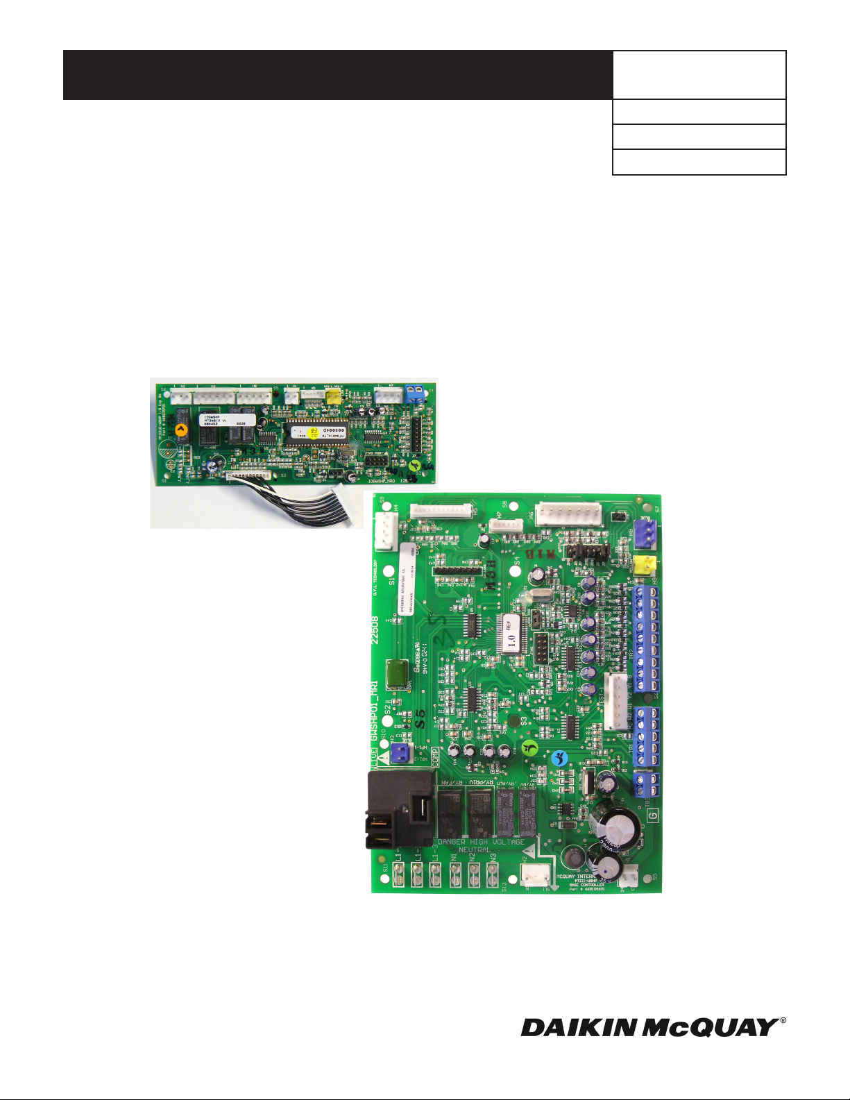
MicroTech® III SmartSource Unit Controller with I/O Expansion Module for
Single and Two Stage Water Source Heat Pump Units, Models GS/GT
I/O Expansion Module
MicroTech III SmartSource Unit Controller
©2012 McQuay International
Page 2

Contents
Introduction ..........................................................................3
Control Boards Terminals and Connectors Descriptions 4
MicroTech III Unit Controller .............................................4
I/O Expansion Module .....................................................5
BACnet Communication Module.......................................5
LonWorks Communication Module .................................5
Replacing a MicroTech III Circuit Board: ........................... 7
Initial Power-Up ...................................................................7
General Use and Information .............................................8
Operating Modes ..............................................................8
Control Inputs (HP, LP, SLTS, COF, U, E, O) .................. 10
Control Outputs {A and IV/PR (H8)}................................10
Unoccupied Operation – Stand Alone Thermostat Control 11
Thermostat Inputs (G, Y1, Y2, W1, and W2) .................. 11
Additional Fault Modes ..................................................... 11
High / Low Pressure Faults (HP/LP) ...............................12
Fan Operation During Most Modes, Faults and
Shutdowns .........................................................................14
Faults and Modes ...........................................................14
Troubleshooting the Water Source Heat Pump Unit ......16
Microtech® III Unit Controller Interface to External
Equipment ..........................................................................17
Appendix A .........................................................................17
Operation and Maintenance of I/O Expansion Module ...17
Introduction .....................................................................17
Initial Power up ..................................................................17
Operation ............................................................................18
Thermostat Inputs ...........................................................18
Electric Heat Controls .......................................................18
Supplemental Electric Heat Control ................................18
Boilerless Heat Control ...................................................18
Compressor Heating Source Selection ...........................19
Fan Speed Control .............................................................19
I/O Expansion Module Faults and Fan Operating Modes
Tables .................................................................................20
Unit Options: ......................................................................21
Waterside Economizer ....................................................21
SmartSource Dehumidication ........................................21
Hot Gas Reheat Smart Dehumidication ........................21
Simplied Dehumidication.............................................22
Humidistat Controlled Dehumidication ..........................22
Dehumidication Only: ....................................................24
MicroTech III Unit Controller with LonWorks®
Communication Module ..................................................25
MicroTech III Controller with an Optional BACnet®
Communication Module ..................................................26
Appendix C – Typical Wiring Diagrams ......................27-35
115V, 1Ph – Model WGS, MicroTech III SmartSource Unit
Controller with BACnet Communication Module
(Hot Gas Reheat) (See page 28 for Service & Disconnect
Wiring) ............................................................................27
265V, 1Ph – Model WGS-WGT, MicroTech III SmartSource
Unit Controller with BACnet Communication Module (Hot
Gas Reheat) (See page 30 for Service & Disconnect
Wiring) ............................................................................29
208-230V, 1Ph – Model WGS-WGT, MicroTech III
SmartSource Unit Controller with BACnet Communication
Module (Waterside Economizer, Desuperheater, 115V Loop
Pumps & 20kW Electric Heat) (See page 32 for Service &
Disconnect Wiring)..........................................................31
208-230V, 3Ph – Model WGS-WGT, MicroTech III
SmartSource Unit Controller with BACnet Communication
Module (Waterside Economizer, 230V Loop Pumps &
5kW Electric Heat) (See page 34 for Service & Disconnect
Wiring) ............................................................................33
460V, 3Ph – Model WGS-WGT, MicroTech III SmartSource
Unit Controller with BACnet Communication Module
(Waterside Economizer, 230V Loop Pumps & 20kW
Electric Heat) (See page 36 for Service & Disconnect
Wiring) ............................................................................35
Controller Comparison ....................................................37
Page 3

Introduction
This installation and operation manual covers the MicroTech® III unit controller for Daikin McQuay G-Series Water
Source Heat Pumps. For information on LonWorks® or
BACnet® communication modules and other ancillary components, see:
■ IM 927 - MicroTech III Water Source Heat Pump
LonWorks Communication Module.
■ IM 928 - MicroTech III Water Source Heat Pump Unit
Controller BACnet MS/TP Communication Module.
■ IM 933 - LonWorks Plug-In Software for use
with MicroTech III Unit Controller - LonWorks
Communication Module.
■ IM 952 - Multiple Unit Control Panel (MUCP) for use
with MicroTech III Unit Controller and Mark IV Unit
Controller.
■ IM 955 - MicroTech III Water Source Heat Pump Wall-
Mounted Room Temperature Sensors.
■ IM 956 - Temperature Sensors for Units with MicroTech
III Unit Controller and LonWorks Communication
Module.
OM 1149 / Page 3 of 40
Page 4
Control Boards Terminals and Connectors Descriptions
MicroTech III Unit Controller
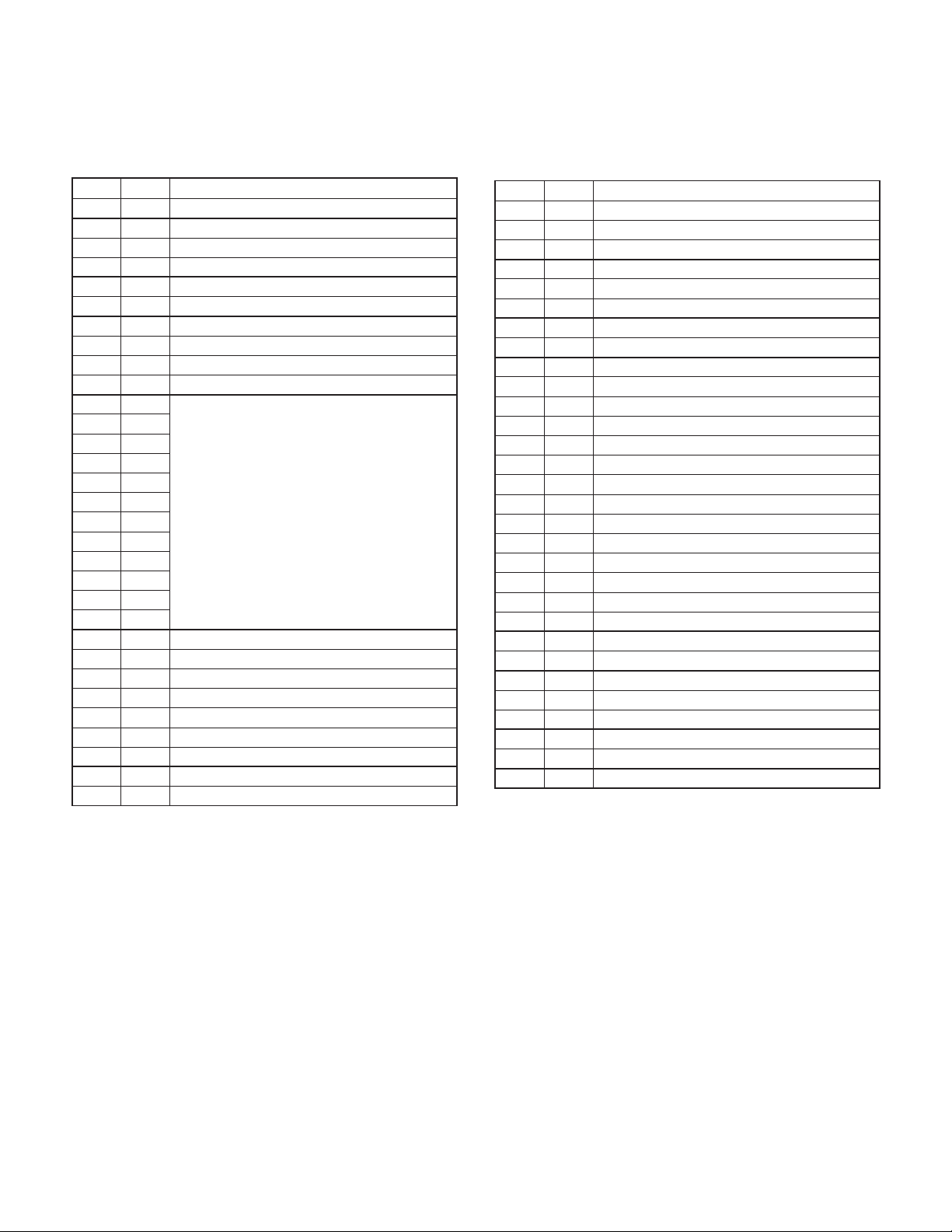
Table 1: MicroTech III Unit Controller Terminals &
Descriptions
H1 – 1 24 24 VAC Power Input
H1 – 2 C 24 VAC common
H2 – 1 SL1 Fan Main Required Output – Switched L1
H2 – 2 Blank Terminal
H2 – 3 N Fan Main Required Output – Neutral
H3 – 1 HP1-1 Comp High Pressure Switch (HP1) Input Terminal 1
H3 – 2 HP1-2 Comp High Pressure Switch (HP1) Input Terminal 2
H4 – 1 1 Discharge Air Temp Sensor – Common
H4 – 2 Discharge Air Temp Sensor – Signal
H4 – 3 Leaving Water Temp Sensor – Common
H4 – 4 Leaving Water Temp Sensor – Signal
H5 – 1 1
H5 – 2
H5 – 3
H5 – 4
H5 – 5
H5 – 6
H5 – 7
H5 – 8
H5 – 9
H5 – 10
H5 – 11
H5 – 12
H6 – 1 1 Condensate Overow Signal Input
H6 – 2 Compressor Suction Temp Sensor (LT1) – Common
H6 – 3 Compressor Suction Temp Sensor (LT1) – Signal
H6 – 4 Compressor Low Pressure Switch (LP1) – Source Voltage
H6 – 5 Compressor Low Pressure Switch (LP1) – Signal
H6 – 6 Reversing Valve – Common
H6 – 7 Reversing Valve – Output
H7 – 1 1 No Connection
H7 – 2 No Connection
Connections to I/O Expansion Board
H7 – 3 Red LED Output
H7 – 4 Green LED Output
H7 – 5 Yellow LED Output
H7 – 6 Red-Green-Yellow LED Common
H8 – 1 1 Isolation Valve/Pump Request Relay N/O
H8 – 2 Isolation Valve/Pump Request Relay N/C
H8 – 3 24 VAC Common
H9 – 1 1 Room Temp Sensor & Tenant Override – Signal
H9 – 2 Room Temp Sensor & Tenant Override – Common
TB1 – 1 1 Room Sensor – Status LED Output
TB1 – 2 2 Room Sensor – Fan Mode & Unit Mode Switches
TB1 – 3 3 Room Sensor – Setpoint Adjust Potentiometer
TB1 – 4 4 Room Sensor – Room Temp Sensor & Tenant Override
TB1 – 5 5 Room Sensor – DC Signal Common
TB2 – 1 R 24 VAC
TB2 – 2 A Thermostat – Alarm Output
TB2 – 3 W2 Thermostat – Heat Stage #2 (W2) Input
TB2 – 4 W1 Thermostat – Heat Stage #1 (W1) Input
TB2 – 5 Y2 Thermostat – Cool Stage #2 (Y2) Input
TB2 – 6 Y1 Thermostat – Cool Stage #1 (Y1) Input
TB2 – 7 G Thermostat – Fan Input
TB2 – 8 O Thermostat – Heat Stage #3 (W3) Input
TB2 – 9 C 24 VAC Common
TB3 – 1 E Emergency Shutdown Input
TB3 – 2 U Unoccupied Input
L1 – 1 L1 - 1 Line Voltage Terminal 1
L1 – 2 L1 - 2 Line Voltage Terminal 2
L1 – 3 L1 - 3 Line Voltage Terminal 3
N1 N1 Neutral Terminal 1
N2 N2 Neutral Terminal 2
N3 N3 Neutral Terminal 3
Page 4 of 40 / OM 1149
Page 5
I/O Expansion Module
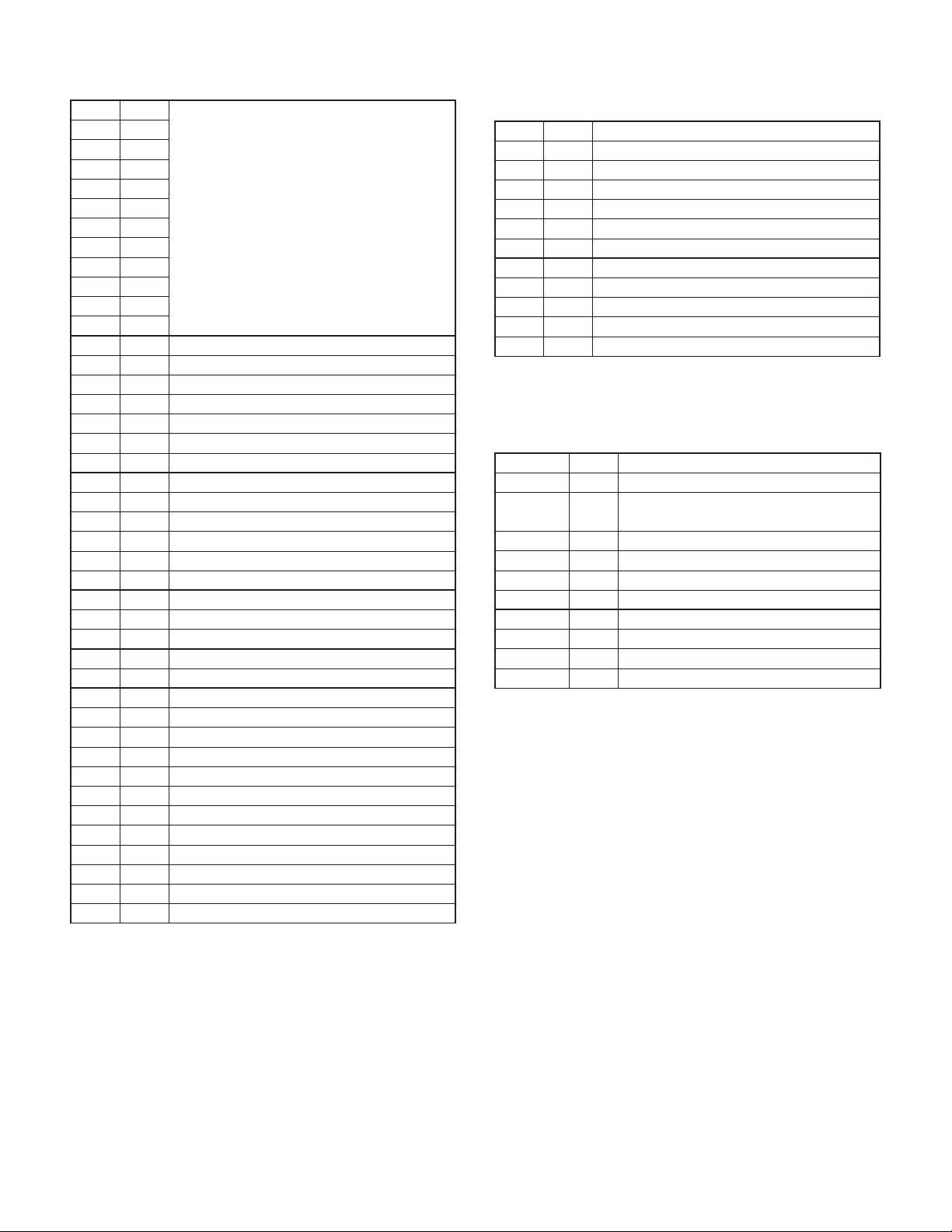
Table 2: I/O Expansion Module Connectors/Terminals
H1 – 1 1
H1 – 2
H1 – 3
H1 – 4
H1 – 5
H1 – 6
H1 – 7
H1 – 8
H1 – 9
H1 – 10
H1 – 11
H1 – 12
H2 – 1 1 Auxiliary Heat Stage #2 Output – N/O
H2 – 2 No Connection
H2 – 3 24 VAC Common
H3 – 1 1 Ext. 24 VAC In
H3 – 2 Ext. 24 VAC Common In
H3 – 3 HGR / Waterside Economizer Output – N/O
H3 – 4 Ext. 24 VAC Common
H3 – 5 ECM Fan Motor Variable Speed Signal Output
H3 – 6 ECM Fan Motor Variable Speed Signal – Common
H4 – 1 1 Entering Water Temp Sensor – Signal
H4 – 2 Entering Water Temp Sensor – Common
H5 – 1 1 No Connection
H5 – 2 No Connection
H5 – 3 Red LED Output
H5 – 4 Green LED Output
H5 – 5 Yellow LED Output
H5 – 6 Red-Green-Yellow LED Common
H6 – 1 HP2-1 Comp High Capacity High Press Sw (HP2) Input Terminal 1
H6 – 2 HP2-2 Comp High Capacity High Press Sw (HP2) Input Terminal 2
H7 – 1 Fan Speed Table Row Select – Signal
H7 – 2 Fan Speed Table Row Select – Common
H7 – 3 Thermostat – Heat Stage #4 (W4) Input – Signal
H7 – 4 Auxiliary 24 VAC Out
H8 – 1 1 Compressor – High Capacity Output – N/O
H8 – 2 24 VAC Common
H8 – 3 No Connection
H8 – 4 Auxiliary Heat Stage #1 Output – N/O
H8 – 5 24 VAC Common
TB1 – 1 1 Humidistat Signal Input
TB1 – 2 2 Thermostat - Heat Stage #4 (W4) Input – Signal
Connections to Main Board
BACnet Communication Module
Table 3: BACnet Communication Module Connectors/
Terminals
P4 – 1 P4 GND
P4 – 2 + 5 VDC
P4 – 3 SPI SELECT (SPI Select To Communications Board)
P4 – 4 SPI CLK (Master Clock)
P4 – 5 SPI RCV (MOSI)
P4 – 6 SPI XMIT (MISO)
P4 – 7 SRDY OUT (SPI Ready To Baseboard)
P4 – 8 No Connection
P3 – 1 P3 Network Signal +
P3 – 2 Network Signal –
P3 – 3 REF
P3 – 4 Shield
LonWorks Communication Module
Table 4: LON Communication Module Connectors/
Terminals
CN_SPI – 1 CN_SPI GND
CN_SPI – 2 + 5 VDC
CN_SPI – 3
CN_SPI – 4 SPI_CLK_0 (Master Clock)
CN_SPI – 5 SPI_RX_0 (MOSI)
CN_SPI – 6 SPI_TX_0 (MISO)
CN_SPI – 7 SREADY_0 (SPI Ready To Baseboard)
CN_SPI – 8 No Connection
TB1 – 1 TB1 Network Signal A
TB1 – 2 Network Signal B
TB1 – 3 REF
SPI_SELECT1_0 (SPI Select To CommunicationsBoard)
OM 1149 / Page 5 of 40
Page 6
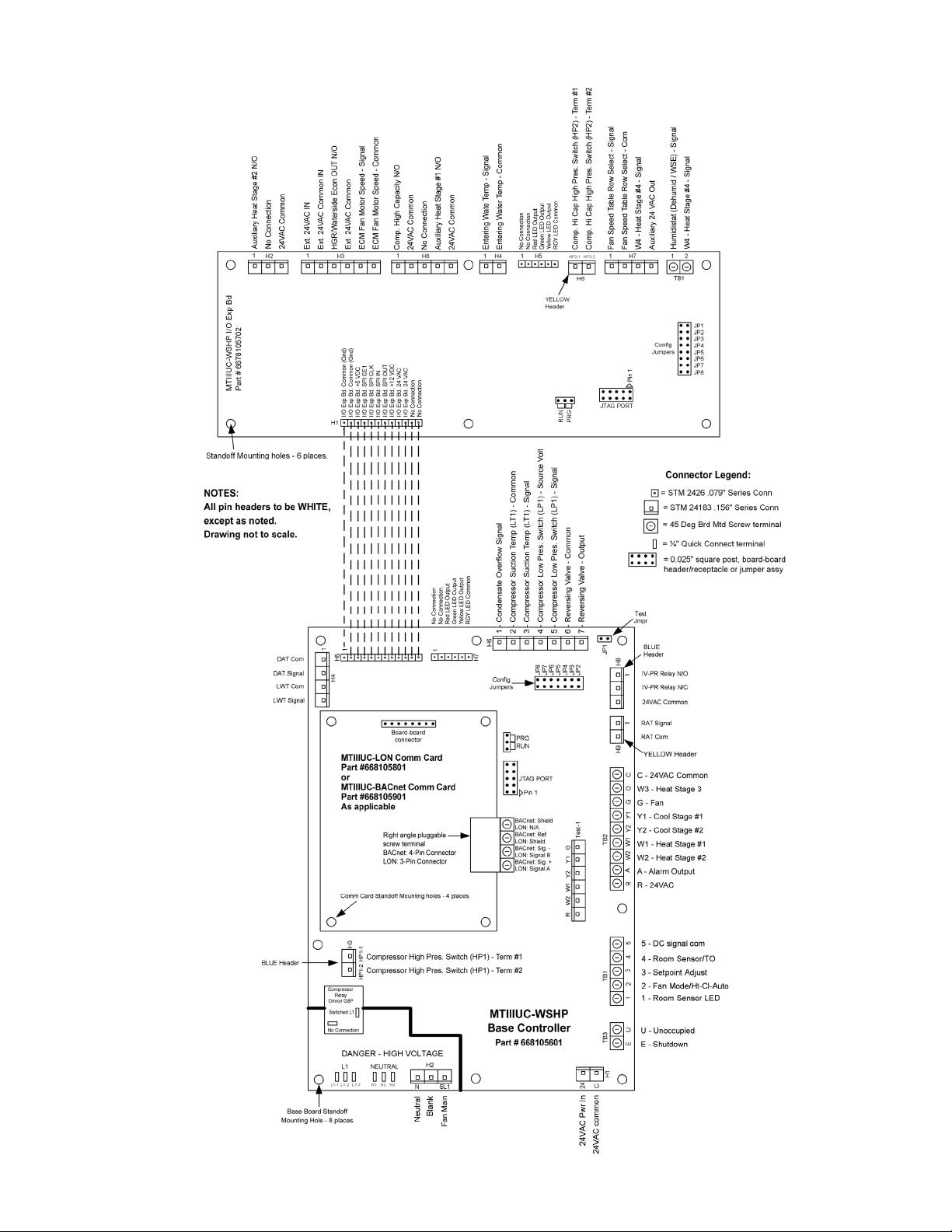
Figure 1: MicroTech III Unit Controller & I/O Expansion Module Connectors Descriptions
Page 6 of 40 / OM 1149
Page 7
CAUTION
Initial Power-Up
The MicroTech III circuit board incorporates static sensitive de-
vices. A static charge from touching the device can damage the
electronic components. To help prevent damage during service,
use static discharge wrist straps.Static discharge wrist straps
are grounded to the heat pump chassis through a 1 Mohm resistor.
Pre start check list:
A random start delay time between 180 and 240 seconds is
generated at power up.
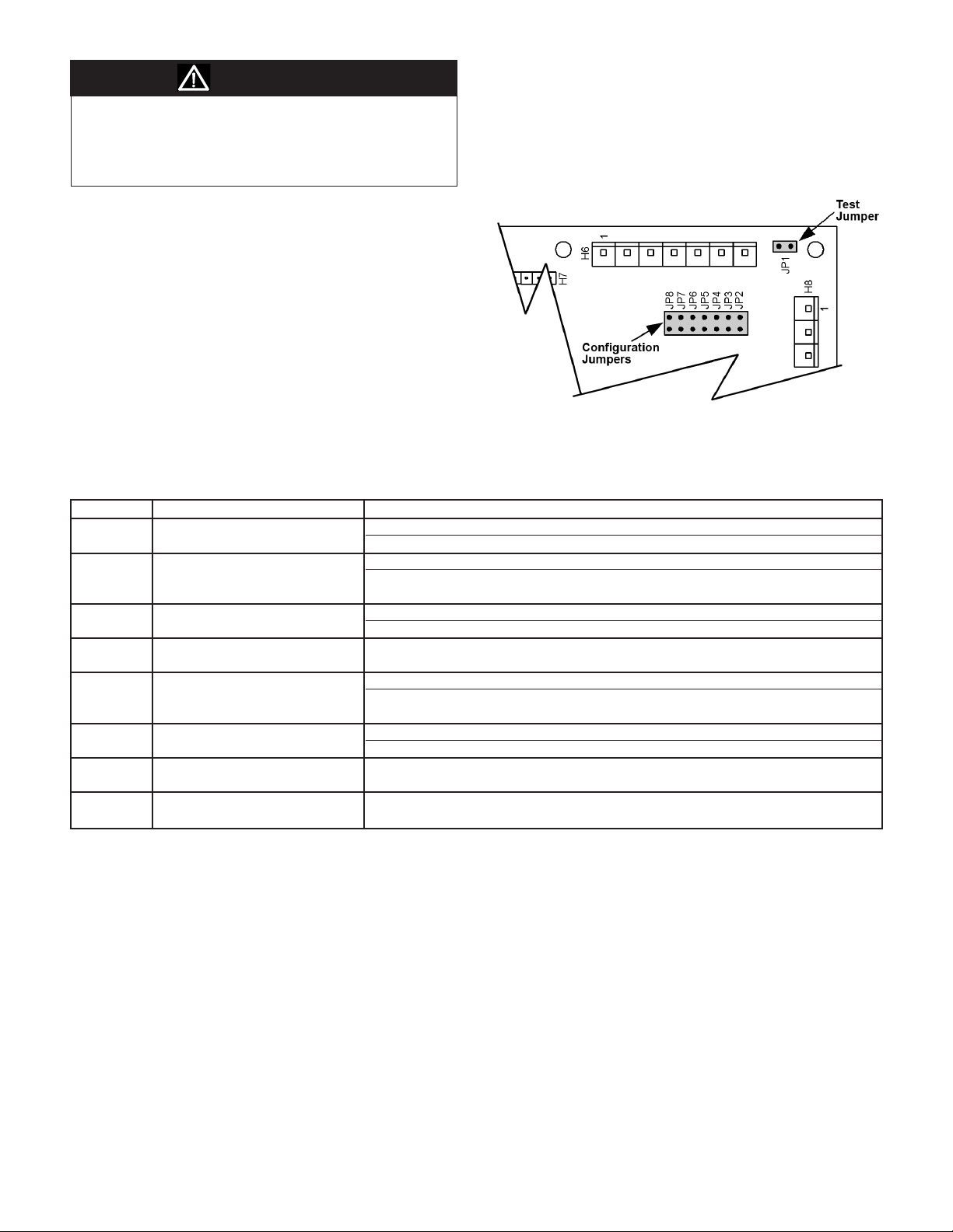
Figure 2: Location of Configuration Jumpers on the Base
Board Controller
Replacing a MicroTech III Circuit Board:
1. Connect wrist strap to unit.
2. Remove faulty board and place on static protected surface.
3. Remove replacement board from static protected bag.
Do not touch circuit board; hold by edges.
4. Holding board in grounded hand, install board in unit.
5. Insert faulty board in empty static bag for return.
Table 5: Configuration Jumper Settings
Jumper Description Options
JP1 Mode
Shorted for service/test operation mode
JP2 Fan operation only applies to Open for continuous fan operation
room sensor control without a Shorted for cycling fan operation
fan mode On/Auto switch
JP3 Freeze protection
Shorted for antifreeze protection
JP4 Freeze fault protection Open for none
Shorted to enable freeze fault protection based on Leaving Water Temperature (LWT)
JP5 Set point adjustment range only Open for adjustment range of -5.0° to +5.0° F
applies to network controls with a Shorted for 55° to 95° F adjustment range
room temperature sensor
JP6 Room control type
Shorted for room temperature sensor control, MicroTech III only
JP7 Compressor heating source Open to enable compressor heating
Shorted to disable compressor heating
JP8 I/O expansion module Open when I/O expansion module is not needed
Shorted when I/O expansion module is required
Open for normal operation mode
Open for water freeze protection
Open for thermostatic room control
OM 1149 / Page 7 of 40
Page 8

General Use and Information
The Microtech III SmartSource unit controller is a water
source heat pump control platform used to control the heat
pump in all modes of operation, including variable speed
fans, two stage compressors, loop pumps, economizers,
reversing valves, and all components used to control conditioned space temperature and humidity. By adding communi-
cations cards, (LonWorks or BACnet) network integration is
possible. The controller can be used with thermostat control
or wall sensor control.
All MicroTech III unit controller inputs must be operated by
dry contacts powered by the control board’s power terminals.
No solid state devices (Triacs) may be used to operate MicroTech III unit controller inputs. No outside power sources may
be used to operate MicroTech III. All units must be properly
grounded per local code requirements. See the Installation
and Maintenance bulletin specic to your Water Source Heat
Pump.
Occupied Operation
The board will be in occupied mode if the unoccupied termi-
nal (U) is not shorted to ground.
Yellow Green Red
Off On Off
Operating Modes
■ Start-up – The unit will not operate until all the inputs
and safety controls are checked for normal conditions.
■ Cooling mode – On an initial call for cooling, the fan
will energize at its “fan only” setting, the pump request
will engergize, the 45 second ow timer will start after
the ow, compressor minimum off, and random startup
timers are expired, the compressor and fan will start at the
stage 1 cooling settings. If room setpoint conditions are
not satised, the fan will operate at the stage 2 cooling
settings. When the room setpoint conditions are satised,
the compressor will shut off and the fan will operate
according to its “fan only” setting when enabled for
continuous fan operation. If fan cycling is enabled, the fan
will turn off once room setpoint conditions are satised.
■ Dehumidication modes – There are four
dehumidication modes of operation;
1. Smart Dehumidication with Hot Gas Reheat
2. Simplied Dehumidication
3. Humidistat Controlled Dehumidication
4. Dehumidication Only
See "SmartSource Dehumidication" on page 21 for details.
▪ Smart Dehumidication – Uses hot gas reheat,
a humidistat, a 2-stage thermostat and air ow
management for precise humidity control. When the
cooling and heating temperature setpoint is satised
and there is a call for dehumidication, maximum
dehumidication is initiated by energizing the
fan at its “fan only” setting, energizing the pump
Board LED Status – Occupied
request, engergizing the 30 second proof-of-ow
timer, energizing the hot gas reheat solenoid valve,
energizing the compressor at maximum cooling, and
energizing the fan at the dehumidication setting.
When the room humidity conditions are satised,
the compressor will shut off and the fan will operate
according to its “fan only” setting when enabled for
continuous fan operation. If fan cycling is enabled, the
fan will turn off, once room humidity conditions are
satised.
▪ Simplied Dehumidication – Uses a 3-stage
thermostat and air ow management to optimize unit
capacity and fan speed for maximum latent capacity
while decreasing room humidity levels. On a call for
cooling, the fan will energize at its “fan only” setting,
the pump request will energize, the 30 second ow
timer will start, after the ow, compressor minimum
off, and random startup timers are expired, the
compressor will start at stage 1 cooling and the fan
will energize at its dehumidication setting. If the
room setpoint temperature is still not satised, the fan
will be energized at the stage 1 cooling settings. If
the room setpoint temperature is still not satised, the
compressor and fan will operate at the stage 2 cooling
settings. When the room temperature conditions are
satised, the compressor will shut off and the fan
will operate according to its “fan only” setting when
enabled for continuous fan operation. If fan cycling
is enabled, the fan will turn off, once room setpoint
conditions are satised.
▪ Humidistat Controlled Dehumidication – Uses
a humidistat and 2-stage thermostat to control room
humidity levels. On a call for dehumidication, the
fan will energize at its “fan only” setting, the pump
request will energize, the 30 second ow timer will
start, after the ow, compressor minimum off, and
random startup timers are expired, the compressor
will start at stage 1 cooling and the fan will energize
at its dehumidication setting. If the room setpoint
temperature is not satised, the fan will be energized
at the stage 1 cooling settings. If the room setpoint
temperature is still not satised, the compressor and
fan will operate at the stage 2 cooling settings. When
the room temperature and humidity conditions are
satised, the compressor will shut off and the fan
will operate according to its “fan only” setting when
enabled for continuous fan operation. If fan cycling
is enabled, the fan will turn off once room setpoint
conditions are satised.
▪ Dehumidication Only – Uses a humidistat in the
cooling only mode. On a call for dehumidication, the
fan will energize at its “fan only” setting, the pump
request will energize, the 30 second ow timer will
start, after the ow, compressor minimum off, and
random startup timers are expired, the compressor
will start at stage 1 cooling and the fan will energize
Page 8 of 40 / OM 1149
Page 9

at its dehumidication setting. Room temperature
conditions are not monitored or maintained. The unit
only responds to a call for dehumidication. When the
room humidity conditions are satised, the compressor
will shut off and the fan will operate according to its
“fan only” setting when enabled for continuous fan
operation. If fan cycling is enabled, the fan will turn
off once room setpoint conditions are satised.
■ Heating mode – On an initial call for heating, the fan will
energize at its "fan only" setting, the pump request
will energize, the 30 second ow timer will start,
after the ow, compressor minimum off, and random
startup timers are expired, the compressor and fan will
start at stage 1 heating settings; the reversing valve
shall energize 5 seconds after the compressor turns
on. If room setpoint conditions are not satised, the
fan will operate at stage 2 heating settings. When the
room setpoint conditions are satised, the compressor
will shut off and the fan will operate according to its
“fan only” setting when enabled for continuous fan
operation. If fan cycling is enabled, the fan will turn
off, once room setpoint conditions are satised.
■ Boilerless Electric Heat mode – When the entering water
temperature is below setpoint, the compressor will not
be allowed to operate. On an initial call for heating,
stage 1 electric heat will be energized and the fan will
start at its electric heat setting. For units equipped with
2 stages of electric heat, if room setpoint conditions
are not satised, the second stage of electric heat
will be energized and the fan will continue to operate
at its electric heat setting. When the room setpoint
conditions are satised, electric heat will be de-
energized and the fan will continue to operate at its
“fan only” setting when enabled, for continuous fan
operation. If fan cycling is enabled, the fan will turn
off after 30 seconds once room setpoint conditions are
satised.
■ Supplemental Electric Heat mode – On an initial call
for heating, the fan will energize at its “fan only”
setting, the pump request will energize, the 30 second
ow timer will start. After the ow, compressor
minimum off, and random startup timers are expired,
the compressor and fan will start at stage 1 heating
settings; the reversing valve shall energize 5 seconds
after the compressor turns on. If room setpoint
conditions are not satised, the fan will operate at
stage 2 heating settings. If room setpoint conditions
are still not satised, the compressor will continue
to operate and stage 1 electric heat will be energized
and the fan will operate at its electric heat setting. For
units equipped with 2 stages of electric heat, if room
setpoint conditions are still not satised, the second
stage of electric heat will be energized and the fan will
continue to operate at its electric heat setting. When
the room setpoint conditions are satised, electric
heat will be de-energized allowing the compressor
to remain on if necessary to maintain room setpoint
conditions. The fan will operate according to its
“fan only” setting when enabled, for continuous fan
operation. If fan cycling is enabled, the fan will turn
off once room setpoint conditions are satised.
■ Primary Electric Heat mode – On an initial call for
heating, stage 1 electric heat will be energized and
the fan will start at its electric heat setting. For units
equipped with 2 stages of electric heat, if room
setpoint conditions are not satised, the second stage
of electric heat will be energized and the fan will
continue to operate at its electric heat setting. When
the room setpoint conditions are satised, electric
heat will be de-energized and the fan will continue
to operate at its “fan only” setting when enabled, for
continuous fan operation. If fan cycling is enabled, the
fan will turn off after 30 seconds once room setpoint
conditions are satised.
■ Emergency Electric Heat mode – A 24v control signal
from the thermostat will initiate a call for stage 1 or stage
2 electric heat. The compressor will not operate and the
fan will start at its electric heat setting.
■ Occupied Mode – The MicroTech III SmartSource unit
controller will manage occupied and unoccupied modes
of operation. The occupancy mode can be established by
a BACnet or LonWorks communication signal, from a
room sensor equipped with “Occupied/Unoccupied” mode
functions, or a thermostat equipped with an “Occupied/
Unoccupied” mode switch. When in the occupied
mode, the unit will be controlled to its occupied setpoint
conditions. The occupancy state will be displayed on
sensors equipped with “Occupied/Unoccupied” mode
functions and annunciation capabilities.
■ Unoccupied Mode – When operating in the unoccupied
mode, the unit will be controlled to its unoccupied setpoint
conditions and the fan will cycle according to a call for
cooling, dehumidication or heating. A simple “grounded”
signal between terminals U and C on the MicroTech
III SmartSource unit controller will place the unit into
the unoccupied mode for night setback operation. The
occupancy state will be displayed on sensors equipped
with “Occupied/Unoccupied” mode functions and
annunciation capabilities.
■ Override Mode – A momentary (4 to 9 seconds) press of
the “Override” button on the thermostat or room sensor
during the unoccupied mode will cause the unit to operate
in the occupied mode for two hours, for after-hours
heating, cooling or dehumidication. “OVERRIDE” will
be displayed on sensors equipped with override button and
annunciation capabilities.
OM 1149 / Page 9 of 40
Page 10

■ “Energy Save” Bypass Mode – BACnet or LonWorks
units can receive a signal from the Building Automation
System (BAS) to initiate the energy savings mode. This
mode is typically initiated by the BAS with smart grid
technologies to save energy. The savings is driven by
reducing peak electrical demand for the building. Once
initiated, the MicroTech III SmartSource unit controller
will reset its effective setpoint to minimize the stage
of compressor operation. “E-SAVE” will be displayed
on sensors equipped with bypass mode annunciation
capabilities.
■ Motorized Water Valve or Pump Start – When there
is a call for cooling, dehumidication or heating, the
MicroTech III SmartSource unit controller will energize
its IV/PR (H8) terminal to open the motorized water
valve or start the loop pump 30 seconds prior to starting
the compressor. The IV/ PR (H8) terminal may be “daisy
chained” between 200 units.
Control Inputs (HP, LP, SLTS, COF, U, E, O)
The control inputs are High Pressure (HP), Low Pressure
(LP), Suction Line Temperature Sensor (SLTS), Condensate
Overow (COF), Unoccupied (U), and Remote Shutdown
(E). The control inputs are in normal states during occupied
mode. The state of each control in occupied mode during
normal operation is as follows:
■ High Pressure (HP): Normally closed switch that opens
on a high refrigerant pressure condition. Control will
generate a high pressure fault and disables the compressor
output when the switch is open.
■ Low Pressure (LP): Normally closed switch that opens on
a low refrigerant pressure condition. Control will generate
a low pressure fault when the switch is open. Suction Line
Temperature Sensor (SLTS): temperature sensor on the
suction line.
■ Condensate Overow (COF): senses condensate level
in condensate pan. Control will generate a fault when
condensate level is too high.
■ Unoccupied (U): Grounding this terminal puts the control
into unoccupied mode.
■ Remote Shutdown (E): Grounding this terminal forces the
control to shutdown the unit.
Control Outputs {A and IV/PR (H8)}
The control outputs are Alarm Fault (A) and Isolation Valve
/ Pump Request {IV/PR (H8)}. The operation of the control
outputs during occupied mode is as follows:
■ The thermostat alarm output will be energized when there
are fault conditions presently active. Without any fault
conditions active, the alarm output shall be de-energized.
■ Isolation Valve / Pump Request {IV/PR (H8)}: is
selectable to be energized when the compressor is
off (normally closed), or when the compressor is
on (normally open), by moving the wire lead to the
appropriate terminal.
Figure 3: H8 Terminals on MicroTech III Board
■ Reversing Valve: 24V signal that is energized upon a call
for heat mode.
■ Compressor Relay: Line or low voltage output used to
control compressor. (On/Off)
Fan Operation
The G terminal controls continuous fan operation. The fan
runs continuously when the G terminal is energized. When the
G terminal is de-energized, the fan cycles with the compressor.
Cooling Mode
The Y1 terminal controls the Cooling Mode of operation.
When the Y1 terminal is energized (24VAC), the following
occurs:
1. The fan energizes.
2. The IV/PR (H8) control output de-energizes or energizes
depending on the H8 terminal wiring (refer to Table 1 on
page 4 & Figure 1 on page 6).
3. The compressor energizes after 30 seconds.
4. The reversing valve de-energizes 5 seconds after the
compressor turns on.
When the Y1 terminal is de-energized, the following occurs:
1. The compressor de-energizes.
2. The IV/PR (H8) control output energizes or de-energizes
depending on the H8 terminal wiring (refer to Table 1 on
page 4 & Figure 1 on page 6).
3. The fan de-energizes, unless the G terminal is energized
(24VAC).
Note: To prevent compressor cycling and all compressors
from starting up together after loss of power, the
required minimum on/off time default is 180 seconds.
This may cause the compressor time delay to be
longer than indicated above.
Page 10 of 40 / OM 1149
Page 11
Heating Mode
The W1 terminal controls the occupied Heating Mode of
operation. When the W1 terminal is energized, the following
occurs:
1. The fan energizes.
2. The IV/PR (H8) control output de-energizes or energizes
depending on the H8 terminal wiring (refer to Table 1 on
page 4 & Figure 1 on page 6).
3. The compressor energizes after 30 seconds.
4. The reversing valve energizes 5 seconds after the
compressor turns on.
When the W1 terminal is de-energized, the following occurs:
1. The compressor de-energizes.
2. The IV/PR (H8) control output energizes or de-energizes
depending on H8 terminal wiring (refer to Table 1 on page
4 & Figure 1 on page 6).
3. The fan de-energizes, unless the G terminal is energized.
Note: To prevent compressor cycling, the required minimum
on/off time default is 180 seconds. This may cause
the compressor time delay to be longer than indicated
above.
Unoccupied Operation – Stand Alone Thermostat Control
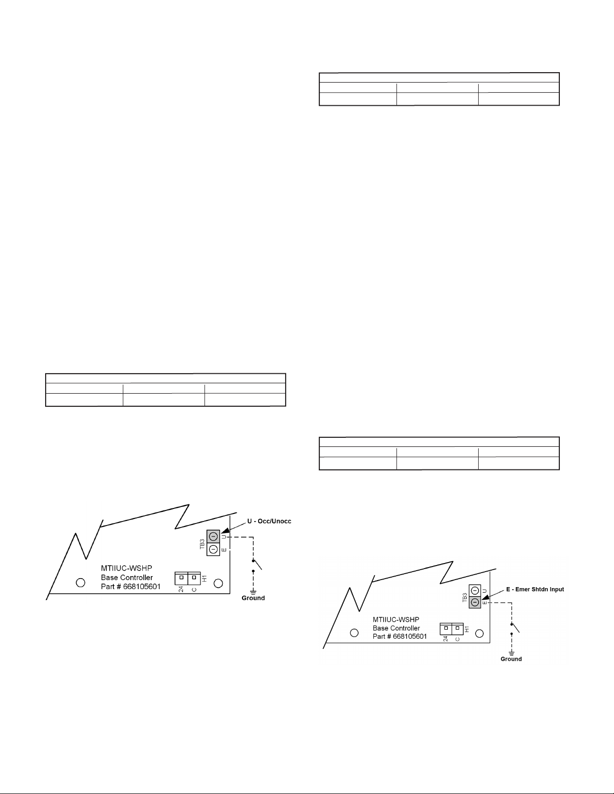
The board will be in unoccupied mode if the unoccupied
terminal (U) is grounded.
Yellow Green Red
On On Off
Board LED Status – Unoccupied
Thermostat Inputs (G, Y1, Y2, W1, and W2)
The only thermostat inputs used during unoccupied operation
are Y2 and W2, which when energized will activate Cooling
Mode or Heating Mode respectively. Inputs G, Y1 and W1
have no effect during unoccupied mode.
Figure 4: Terminal "U" - Grounded for Unoccupied
Additional Fault Modes
Brownout
Yellow Green Red
Off Flash Off
Brownout condition is provided to protect the water source
heat pump’s motor electrical damage due to low voltage
conditions.
The MicroTech III unit controller is designed to monitor the
24VAC power supply to the board. If the line voltage supplied to the water source heat pump drops, the 24VAC supply
to the control board will also drop. When the line voltage
supplied to the unit drops below approximately 80% of the
unit nameplate rated value, the controller goes into brownout
condition. The controller remains in brownout condition until
line voltage returns to approximately 90% of the unit nameplate value.
When in brownout condition, thermostat and control inputs
have no affect upon unit operation. Remote shutdown and
brownout conditions have the same level of priority. See "Pri-
ority Level of Faults and Modes" on page 14.
When the unit is in brownout condition the following occurs:
1. The compressor de-energizes.
2. The fan de-energizes.
3. Fault terminal (A) energizes (fault). A to R will be used to
indicate an alarm signal.
When the line voltage supplied to the unit returns to accept-
able levels (~90% of nameplate) the controller returns to the
current mode.
Remote Shutdown
Yellow Green Red
Off Flash Off
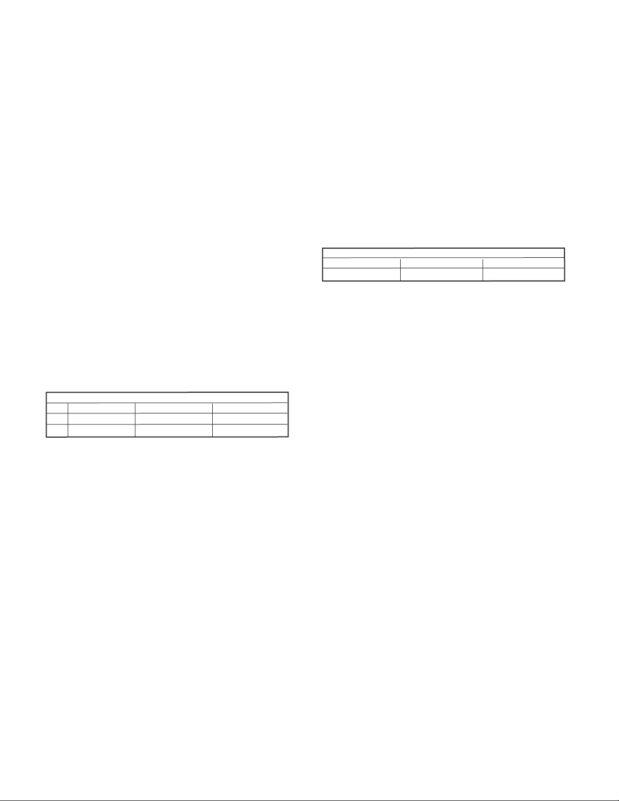
When the E terminal is grounded, the MicroTech III unit
controller enters remote shutdown mode. Remote shutdown
is provided so that when properly connected to a building
automation system, remote switch, etc., the E terminal can be
used to shut down the water source heat pump.
Figure 5: Terminal "E" - Grounded for Remote Shutdown
Board LED Status – Brownout
Board LED Status – Remote Shutdown
OM 1149 / Page 11 of 40
Page 12
When in remote shutdown (E terminal grounded), thermostat
and control inputs have no affect upon unit operation. No faults
or modes have higher priority than remote shutdown. Remote
shutdown and brownout condition have the same level of
priority. See "Priority Level of Faults and Modes" on page 14.
When the unit is in remote shutdown mode, the following
occurs:
1. The compressor de-energizes (if enabled).
2. The fan de-energizes (if enabled).
3. Fault terminal (A) will remain de-energizes because
emergency shutdown is a "mode". A to C will be used to
indicate normal operation.
When the E terminal is no longer grounded the unit will automatically return to normal operation.
Note: The remote shutdown input (E) will suspend unit
operation. Disconnect power when servicing the unit/
controller.
High / Low Pressure Faults (HP/LP)
Normally closed high and low refrigerant pressure switches
help protect the water source heat pump from excessively
high or low refrigerant pressures. The MicroTech III unit controller monitors these switches individually. If the compressor
is running and the HP circuit is open, the controller enters
a pressure fault mode. If the LP circuit is open after a time
delay (default of 30 seconds, adjustable if a communication
module is present) the controller enters a low pressure fault
mode.
Yellow Green Red
HP Off Off Flash
LP Off Off Solid
See "Priority Level of Faults and Modes" on page 14..
When the unit is in high or low pressure fault modes the following occurs:
1. The compressor de-energizes.
2. The IV/PR(H8) output will change state. (On to Off / Off
to On).
3. The fan de-energizes.
4. The fault terminal (A) energizes (fault). A to R will be
used to indicate an alarm signal.
High Pressure Reset
After the HP circuit is closed, the unit does not return to
normal operation until the alarm is manually reset. The unit is
locked out in this manner until the unit can be serviced.
The alarm is reset by a short interruption of unit power, by
holding down the tenant override button for more than 10
seconds, or via the Building Automation System (BAS).
Low Pressure Reset
The low pressure switch fault is subject to intelligent reset.
If the pressure recovers, it resets two times within a 24-hour
time period. If further faults are detected within the 24 hours,
the controller must be manually reset as described in the High
Pressure Reset section above.
Board LED Status – High/Low Pressure Faults
Low Suction Temperature Fault Heating
1. The control will attempt to recover from a low suction
temperature condition by defrosting water heat exchanger
(coaxial coil).
2. See the Defrost Process below for details.
Low Suction Temperature Fault Cooling
1. When the suction line temperature falls below 28° F
disable the compressor output only.
2. The fan will continue to run drawing warmer air over the
air heat exchanger.
3. When the suction line temperature increases by Low Temp
Protect Diff (the default is 8° F) degrees.
4. The compressor is available for cooling if the Compressor
Minimum Off timer has expired.
5. Mark the occurrence of the fault.
Yellow Green Red
Flash Off Off
Board LED Status – Low Suction Line Temperature Fault
Defrost Sequence of Operation:
1. Immediately turn off the compressor if operating in the
cooling or dehumidication modes.
2. The fan will remain on at the existing fan speed if the unit
is cooling, dehumidifying or congured for electric heat
3. The reversing valve output is de-activated, placing the
reversing valve in the cooling mode and moving warm
refrigerant to the coax coil.
4. Fan speed is not changed, however “Heat Stage #1” speed
is used if the fan is presently off.
5. If the compressor was on at the beginning of the defrost
process, then start the 60 second xed defrost timer.
6. Wait for the defrost timer to expire.
7. If the alarm condition has cleared:
· Return to normal operation.
8. If the alarm condition remains active:
• Compressor High Capacity is turned off
• Compressor is immediately turned off, ignoring the
Compressor Minimum ON timer
• Compressor is disabled for heating and cooling
• Electric heating can be used if it is available
• Fan and pump remain available for operation
Heating Mode
When the suction line temperature falls below 28°F on standard equipment (6.5°F on Geothermal) the low temperature
fault generates the following:
■ The reversing valve de-energizes. The compressor and fan
continue to operate in cooling mode for 60 seconds, which
results in a defrost mode. This defrosts any ice that may
have accumulated in the water-to-refrigerant coil, because
of a lack of condenser water ow in heat mode.
■ In heat mode the low temperature fault is subject to
Intelligent Reset.
Page 12 of 40 / OM 1149
Page 13

■ The fault terminal (A) energizes while the unit is in defrost
mode. It will stay energized until the temperature recovers
to 36°F for standard equipment (14.5°F for geothermal). A
to R will be used to indicate an alarm signal. The previous
operation of heating or cooling determines how the low
suction temp alarm must be reset.
■ The fan and pump remain available for operation.
Cooling Mode
When the suction line temperature falls below 28°F standard
equipment (28°F geothermal) in cool mode the:
■ Compressor de-energizes.
■ The fan and pump remain available for operation.
■ Alarm output energizes.
■ When the suction line temperature recovers to 36°F
standard equipment (14.5°F on geothermal) the low
temperature fault continues and the compressor will be
locked out.
Fan Only Mode
When the suction line temperature falls below 28°F standard
equipment (28°F geothermal) in cool mode the:
■ The fan and pump remain available for operation.
■ Alarm output energizes.
The previous operation of heating or cooling determines how
the low suction temp alarm must be reset.
Condensate Overow
Yellow Green Red
On Off Off
Board LED Status – Condensate Overow
The MicroTech III unit controller's condensate sensor is
designed to detect excessively high condensate water levels in
the drain pan. When high condensate water levels are detect-
ed during cooling or dehumidication modes, the controller
enters into condensate fault mode. The fan operates normally
during the condensate overow fault mode.
Some faults and modes have higher priority than condensate
overow mode. See "Priority Level of Faults and Modes" on
page 14.
When the unit senses a condensate overow fault while in
cooling mode the following occurs:
1. The compressor de-energizes.
2. The fault terminal (A) energizes (fault). A to R will be
used to indicate an alarm signal.
When condensate levels return to normal, the controller will
automatically return to normal operation.
Remote Reset of Automatic Lockouts
The Remote Reset feature provides the means to remotely
reset some lockouts generated by high-pressure and/or lowtemperature faults. When the MicroTech III unit controller
is locked out due to one of these faults, and the cause of the
fault condition has been cleared, energizing the O-terminal
for 11 seconds or more forces the MicroTech III unit controller to clear the lockout. Cycling unit power also clears a lockout if the conditions causing the fault have been alleviated.
Intelligent Reset (See Table 6)
The Intelligent Reset feature helps to minimize nuisance trips
of automatic lockouts caused by low pressure or low-tem-
perature faults. This feature clears faults the rst two times
they occur within a 24-hour period and triggers an automatic
lockout on the 3rd fault. The retry count is reset to zero every
24 hours.
Table 6: Fault Recovery and Reset
Button Reset
IO Expansion Communication Fail Yes No No
Invalid Jumper Conguration No No No
Low Voltage Brownout Yes No Yes
All Sensor Failures No No Yes
Compressor High Pressure No Yes Yes
Compressor Low Pressure Yes
Compressor Low Suction Temp or Freeze Fault Detect
(In Heating Mode)
Compressor Low Suction Temp or Freeze Fault Detect
(In Cooling or Dehumidication Modes)
Condensate Overow Yes No Yes
Low Entering Water Temp. Yes No No
EEPROM Corrupted No No No
Waterside Economizer Low Temp. Cutout Yes No No
Note: 1 Indicates auto recover is subject to intelligent alarm reset. Alarm auto recovers on rst two occurrences, locked out on third
within 24 hour period. See “Intelligent Alarm Resetting” section on the previous page for further details.
Fault Description
Yes1 Yes Yes
Auto Recovery
1
No Yes Yes
Tenant Override
Yes Yes
Network Reset
OM 1149 / Page 13 of 40
Page 14

Tenant Override
Note: It is recommended that the "All MicroTech III unit
controller inputs must be operated by dry contacts
powered by the control board’s power terminals. No
solid state devices (Triacs) may be used to operate
MicroTech III unit controller inputs. No outside power
sources may be used to operate MicroTech III. All
units must be properly grounded per local code
requirements. See the Installation and Maintenance
bulletin specic to your Water Source Heat
Pump." and "Unoccupied Operation – Stand Alone
Thermostat Control" sections be reviewed prior to this
section.
The MicroTech III unit controller enters tenant override mode
when the Tenant Override (TO) terminal is grounded for 4-10
seconds during a period when the Water Source Heat Pump is
in unoccupied mode.
Tenant override allows a tenant, returning to the controlled
space after the unit has been placed in unoccupied mode, to
activate the tenant override input and place the unit into occupied mode.
Any remote button or switch with momentary dry contacts
can be used for this purpose. During the 2-hour tenant override period all the thermostat inputs will be used, (see "Oc-
cupied Operation" on page 8) for unit operation. If the U
terminal is still grounded after the 2-hour time limit, the unit
will return to unoccupied mode. Refer to "Unoccupied Opera-
tion – Stand Alone Thermostat Control" on page 11.
Fan Operation During Most Modes, Faults and Shutdowns
The MicroTech III unit controller allows fan operation during
most modes, faults and shutdowns to facilitate maximum
space comfort and control. However, the fan does not operate
during brownout or emergency shutdown condition. During
most modes, faults, or shutdowns the fan will operate
normally:
may be damaged.
Table 7: Room Sensor Status LED
LED On
Time (Sec)
0.5 0.5
0.0 Continually Tenant Override is Active
0.5 5.5 Unoccupied Mode
5.5 0.5 Standby Mode
Continually 0.0 Occupied or Bypass Modes
LED Off
Time (Sec)
Operating Mode
Alarm Condition or Network “Wink”
Operation Active
Faults and Modes
Table 8: Priority Level of Faults and Modes
Priority Level Mode or Fault
1 I/O Expansion Communication Fail
2 Invalid Conguration
3 Low Voltage Brownout
4 Emergency Shutdown Mode
5 Compressor High Pressure
6 Compressor Low Pressure
7 Compressor Suction Temp Sensor Fail
8 Compressor Low Suction Temp
9 Freeze Fault
10 Room Temp Sensor Fail
11 Entering Water Temp Sensor Fail
12 Leaving Water Temp Sensor Fail
13 Condensate Overow
14 Low Entering Water Temp
15 Serial EEPROM Corrupted
16 Waterside Economizer Low Temp Cutout
17 Service Test Mode
Operation with the High Speed Jumper
■ The MicroTech III unit controller includes a high-speed
jumper terminal labeled JP1 to speed system check out
and trouble-shooting. See Figure 2 on page 7 for JP1
location.
Note: This jumper is intended for factory unit testing and
should only be used by trained service technicians as
several timing functions are reduced to speed system
check out.
■ Disconnect power to the unit when installing or removing
the high-speed jumper.
■ The high speed jumper should only be used for a short
period of time for testing of the unit’s operation by a
trained service technician. The jumper must be removed
for normal unit operation.
■ If the jumper is left on after system check out, the unit
Page 14 of 40 / OM 1149
Page 15

Table 9: MicroTech III Unit Controller Status LED's
Description Type Yellow Green Red
IO Expansion Communication Fail Fault ON Flash Flash
Invalid Jumper Conguration Fault Flash Flash OFF
Low Voltage Brownout Fault OFF Flash OFF
Emergency Shutdown Mode OFF Flash OFF
Compressor High Pressure Fault OFF OFF Flash
Compressor Low Pressure Fault OFF OFF ON
Compressor Suction Temp Sensor Fail Fault Flash Flash ON
Compressor Low Suction Temp Fault Flash OFF OFF
Freeze Fault Detect Fault Flash OFF Flash
Room Temp Sensor Fail (Room Sensor Control Only) Fault Flash Flash ON
Leaving Water Temp Sensor Fail Fault Flash Flash ON
Condensate Overow Fault ON OFF OFF
Serial EEPROM Corrupted Fault ON ON ON
Waterside Economizer Low Temp Cutout
(WSE Control & Call for Cooling)
Service Test Mode Enabled Mode Flash Flash Flash
Unoccupied Mode Mode ON ON OFF
Occupied, Bypass, Standby, or Tenant Override Modes Mode OFF ON OFF
Mode Flash ON Flash
OM 1149 / Page 15 of 40
Page 16

Troubleshooting the Water Source Heat Pump Unit
Figure 6: Troubleshooting Guide - Unit Operation
Low voltage, check
power supply voltage
Check wiring - loose or
broken and check for faulty
connection
Check relays and contacts,
also capacitor and wiring
Check high pressure switch,
low pressure switch and low
temperature switch to see if
unit is cycling on the safety
Check to see if the reversing
valve is not hung up and is
operating correctly
Check condensate overflow
switch in cool mode of
operation
Check thermostat for
proper location
Fuse may be blown,
circuit breaker is open
Neither fan, nor compressor
runs and all LED lights
are off
Compressor runs
in short cycle
Wire may be loose or broken.
Replace or tighten wires
Fan operates,
Unit
compressor does not
Unit control, check thermostat
for correct wiring or faulty
thermostat
Check capacitor
Check wiring - loose or broken
and check for bad connection
High or Low pressure lockout
A. Cool mode, check water flow
B. Heating mode, check air flow
C. Check reversing valve for
proper valve position
Check compressor overload -
make sure it is closed
Check compressor to ground, or
for internal short to ground
Compressor winding may be
open. Check continuity with
ohm meter
Compressor attempts to
start but does not
Check compressor wiring
for defective wiring or loose
connection
Check for defective
compressor internal windings
with ohm meter
Check for faulty compressor
capacitor
Check for lock rotor amp
draw
Insufficient cooling or
heating
Check thermostat for
improper location
Check for proper air flow filter could be dirty
Check blower assembly for
dirt or faulty fan motor
capacity
Check for low refrigerant
charge
Check amp draw on blower
assembly
Check for proper water flow
and delta T (°F)
Page 16 of 40 / OM 1149
Page 17

Microtech® III Unit Controller Interface to External Equipment
■ The MicroTech III unit controller’s thermostat input
terminals may be directly interfaced with any standard
or night setback thermostat that uses mechanical dry
contacts. Power cannot be supplied from the water
source heat pump for electronic thermostats that require a
separate power supply for their internal operation except
those provided by Daikin McQuay. Only thermostats
offered by Daikin McQuay are proven to operate properly
with the MicroTech III unit controller. Daikin McQuay
makes no guarantees about any other thermostat or control
device interfaced by the end user with the MicroTech III
unit controller.
■ Care must be used to isolate all external power sources
from the MicroTech III unit controller to prevent ground
loops and other unpredictable electrical problems. Only
dry mechanical contacts should be used to operate
or interface with the MicroTech III unit controller’s
thermostat and or control inputs. Use mechanical relays
to isolate two power systems when external equipment
with its own power supply is used to interface with or
control the MicroTech III unit controller’s thermostat and
or control inputs. For example, if you have a Building
Automation System (BAS), controller, etc., and you
wish to use a digital output from the building automation
system or controller that is internally powered, then you
must use an additional mechanical relay (not supplied
by Daikin McQuay) to isolate the MicroTech III unit
controller.
■ Due to the nature of triacs and other solid state devices,
triacs cannot be directly used to operate the MicroTech
III’s unit controller’s thermostat or control inputs. To
interface triacs or other solid state switching devices to the
MicroTech III unit controller inputs, separate them from
the board using mechanical relays. To do this, use the
triac or solid state device to drive a mechanical relay (not
supplied by Daikin McQuay), then use the mechanical
relay’s dry contacts to drive the desired MicroTech III unit
controller input.
■ The MicroTech III unit controller’s valve or pump request
terminal {IV/PR (H8)} is an output signal to external
devices to allow water ow as required by the heat pump.
The IV/PR (H8) terminal follows compressor operation
inversely if connected to the normally open terminal and
simultaneously when connected to the normally closed
terminal. The IV/PR (H8) terminal can be used as a signal
to an external pump or valve to enable ow to the unit.
The compressor start is delayed for 30 seconds after the
IV/PR (H8) output is energized.
Table 10: IV/PR(H8) Terminal and Compressor Operation
IV/PR(H8) Compressor On Compressor Off
Normally Open 24 VAC 0 VAC
Normally Closed 0 VAC 24 VAC
Appendix A
Operation and Maintenance of I/O Expansion Module
Introduction
The I/O Communication Module is an expansion of the main
board and provides extra functionality to the MicroTech III
control system.
■ The MicroTech III unit controller in combination with the
I/O Expansion Module will be the standard control system
for SmartSource Water Source Heat Pumps.
Adding an I/O Expansion Module (with an interconnect
cable) to the main controller allows:
■ Compressor High Capacity On/Off Control
■ Variable Speed Fan Control
■ Water Side Economizer Control
■ Active Hot Gas/Reheat (HGR), or Low Capacity
Dehumidication Options
■ Boilerless & Supplemental Auxiliary Heating Options
■ The fourth thermostat Heating Stage (W4) Input
The I/O Expansion Module has an independent LED annun-
ciator to identify operational fault conditions.
Initial Power up
Figure 7: I/O Expansion Board Configuration Jumper
Terminals
OM 1149 / Page 17 of 40
Page 18

Table 11: I/O Expansion Module Jumper Settings
I/O Expansion Description Jumper(s) Setting Model
Not Used JP1 JP1 = Open
Not Used JP2 JP2 = Open
JP3 = Open
JP4 = Open
Secondary Heating Options JP3 & JP4
Dehumidication Options / Waterside Economizer JP5 & JP6
Not Used JP7 JP7 = Open
Compressor Capacity Option JP8
JP3 = Shorted
JP4 = Open
JP3 = Open
JP4 = Shorted
JP5 = Open
JP6 = Open
JP5 = Shorted
JP6 = Open
JP5 = Open
JP6 = Shorted
JP8 = Open
JP8 = Shorted
Operation
Thermostat Inputs
None
Supplemental Electric Heat
Boilerless Electric Heat
None
Hot Gas/Water Reheat (HGR)
Waterside Economizer
Single-Stage Capacity
Dual-Stage Capacity
Waterside Economizer/ Dehumidication
• The Waterside Economizer/Dehumidication input (TB1-
1), when energized from the thermostat, enables Waterside
Economizer or Dehumidicaiton operation depending on
jumper conguration.
W4
• The W4 (TB1-2) terminal enables the second stage of
electric heat.
Electric Heat Controls
Supplemental Electric Heat Control
The supplemental electric heating option provides addi-
tional stages of heating that can be used in conjunction with
compressor heating, or exclusively if the compressor is not
available for heating.
General Rules:
• Supplemental electric heater and the compressor may
operate simultaneously.
• Minimum Compressor ON and OFF timers do not apply
to electric heat control.
Operation:
Fan Main Output: will turn ON and the Fan PWM signal
will be at “Auxiliary Heat” duty cycle when:
• Any auxiliary heat output is energized.
• For 30 xed seconds after all auxiliary heat outputs have
been de-activated.
Electric Heat Outputs: are allowed to energize when either
condition exists:
• Inter-Stage ON timer must be expired.
• Compressor is not available for heating.
When Compressor is Available:
• Auxiliary Heat Stage #1 output energizes upon activation
of Heating – Stage #3.
• Auxiliary Heat Stage #2 output energizes upon activation
of Heating – Stage #4.
When Compressor is Unavailable:
• Auxiliary Heat Stage #1 output energizes upon activation
of “Heating – Stage #1.
• Auxiliary Heat Stage #2 output energizes upon activation
of Heating – Stage #4.
Boilerless Heat Control
• Turns on the heater when the entering water temperature
is less than setpoint (default is 55°F), the temperature set
point is adjustable through the network.
• For geothermal applications the heater turns on when the
entering water temperature is less than setpoint (default
28°F).
Note: In both cases the compressor is shut down.
Page 18 of 40 / OM 1149
Page 19

Compressor Heating Source Selection
Compressor heating source selection provides a method to
disable the compressor operation when in the heating mode.
Baseboard JP7 conguration jumper operation:
• Open: Enables compressor operation in the heating mode.
• Shorted: Disables compressor operation in the heating
mode.
When compressor operation is disabled in the heating mode
and electric heat is available:
• Auxiliary Heat Stage #1: output energizes upon
activation of the “Heating – Stage #1”.
• Auxiliary Heat Stage #2: output energizes upon
activation of the “Heating – Stage #4”.
When compressor operation is disabled in the heating mode
and electric heat is unavailable:
• The unit will not provide any form of heating.
Fan Speed Control
Fan Speed Selection via four position switch
A 4-position rotary switch located in the control box allows
CFM settings to be eld adjustable. Each position on the
rotary switch represents settings 1-4 (Figure 8).
Figure 8: 4-Position Rotary Fan Speed Switch
• Fan Speed control (located in the unit control box) will
optimize unit fan speed based on thermostat/room sensor
inputs.
• The installer shall have ability to further optimize fan
speeds for specic application requirements by means of
a 4 position rotary switch. (See Unit specic Installation
Manual).
Table 12: Rotary Fan Speed Settings (2-Ton, 2-Stage Unit)
CFM Setting
Setting 4 650 900 650 900 450 600 900
Setting 3 525 800 525 800 400 533 800
Setting 2 470 670 470 670 335 447 800
Setting 1 400 525 400 525 263 350 800
Part Load
Stage 1 Heat
Full Load
Stage 2 Heat
Part Load
Stage 1 Cool
Full Load
Stage 2 Cool
Fan Only Dehumidication
Electric
Heat
OM 1149 / Page 19 of 40
Page 20

I/O Expansion Module Faults and Fan Operating Modes Tables
Table 13: I/O Expansion Module LED & Fault Outputs
Description Type Yellow Green Red
Baseboard Communication Fail Fault Flash OFF Flash
Entering Water Temp Sensor Fail
(Boilerless Electric Heat or Waterside Economizer Only)
Low Entering Water Temperature
(No Display On Boilerless Electric Heat)
Fan is OFF Mode OFF ON OFF
Fan Running at Low Speed (0 to 33%) Duty Cycle Mode OFF Flash OFF
Fan Running at Medium Speed (34 to 66%) Duty Cycle Mode ON Flash OFF
Fan Running at High Speed (67 to 100%) Duty Cycle Mode Flash Flash OFF
Note: Mode / Faults are listed in order of priority.
Fault ON OFF Flash
Fault OFF ON Flash
Table 14: I/O Expansion Module Connectors and Descriptions
H1 – 1 1
H1 – 2
H1 – 3
H1 – 4
H1 – 5
H1 – 6
H1 – 7
H1 – 8
H1 – 9
H1 – 10
H1 – 11
H1 – 12
H2 – 1 1 Auxiliary Heat Stage #2 Output – N/O
H2 – 2 No Connection
H2 – 3 24 VAC Common
H3 – 1 1 Ext. 24 VAC In
H3 – 2 Ext. 24 VAC Common In
H3 – 3 HGR / Waterside Economizer Output – N/O
H3 – 4 Ext. 24 VAC Common
H3 – 5 ECM Fan Motor Variable Speed Signal Output
H3 – 6 ECM Fan Motor Variable Speed Signal – Common
Connections to Main Board
H4 – 1 1 Entering Water Temp Sensor – Signal
H4 – 2 Entering Water Temp Sensor – Common
H5 – 1 1 No Connection
H5 – 2 No Connection
H5 – 3 Red LED Output
H5 – 4 Green LED Output
H5 – 5 Yellow LED Output
H5 – 6 Red-Green-Yellow LED Common
H6 – 1 HP2-1 Comp High Capacity High Press Sw (HP2) Input Terminal 1
H6 – 2 HP2-2 Comp High Capacity High Press Sw (HP2) Input Terminal 2
H7 – 1 Fan Speed Table Row Select – Signal
H7 – 2 Fan Speed Table Row Select – Common
H7 – 3 Thermostat – Heat Stage #4 (W4) Input – Signal
H7 – 4 Auxiliary 24 VAC Out
H8 – 1 1 Compressor – High Capacity Output – N/O
H8 – 2 24 VAC Common
H8 – 3 No Connection
H8 – 4 Auxiliary Heat Stage #1 Output – N/O
H8 – 5 24 VAC Common
TB1 – 1 1 Humidistat Signal Input
TB1 – 2 2 Thermostat - Heat Stage #4 (W4) Input – Signal
Page 20 of 40 / OM 1149
Page 21

Unit Options:
Waterside Economizer
Waterside Economizer Control
• The Microtech III controls the waterside economizer.
Upon a call for economizer operation via TB1-1, the
output to the 3-way diverting valve and the fan motor are
energized, allowing water ow through the economizer
coil and fan operation.
SmartSource Dehumidication
■ Hot Gas Reheat Smart Dehumidication
■ Simplied Dehumidication
■ Humidistat Controlled Dehumidication
■ Dehumidication Only
4. Wiring:
■ Thermostat (Part No. 910121746 or 910121748)/Sensor
(Part No. 667720401) Combination:
Figure 9: Model GT thermostat and sensor combination
hot gas reheat smart dehumidification wiring diagram
Model GT
Unit Thermostat
R R 24VAC
C C Common
G G Fan
Y1 Y1 Cool Stage 1
Y2 Y2 Cool Stage 2
Humidistat
TB-1 R 24VAC
DH Dehumid
Hot Gas Reheat Smart Dehumidication
1. Application:
By utilizing the factory installed hot gas reheat and smart air
ow management; dehumidiation can be achieved in applications where precise humidity control is required.
2. Items Required:
■ Unit with Hot Gas Reheat option
■ Humidistat and a Thermostat OR Digitally Adjustable
Wall Sensor
3. Unit Control Settings:
Figure 10: Model GS thermostat and sensor combination
hot gas reheat smart dehumidification wiring diagram
Model GS
Unit Thermostat
R R 24VAC
C C Common
G G Fan
Y1 Y1 Cool Stage 1
Humidistat
TB-1 R 24VAC
DH Dehumid
■ I/O Expansion Module Jumper Settings:
• JP5=Shorted
• JP6=Open
Figure 11: SmartSource MicroTech III board to digital room temperature sensor wiring
SmartSource Board
Terminal Block Label TB2-1 TB1-1 TB1-2 TB1-3 TB1-4 TB1-5 TB3-1 TB3-2 TB1-1
Unit Status Output
24VAC
Description
Fan & Unit Mode
MicroTech III Board
■ Digitally adjustable room temperature sensor (Part No.
910121754)
Base Board
Emergency Shutdown
Input
Unoccupied Input
Setpoint Adjust
Room Temp Sensor &
Tenant Override
DC Signal Common
I/O Expan-
sion Module
Dehumidication Input
Terminal Label R 1 2 3 4 5 E U 1
Typical Wiring
Terminal Label R (24VAC) 1 (ST) 2 (FM) 3 (SP) 4 (UTS) 5 (GND) 6 (FC) E U DH
Unit Status Output
24VAC
Description
Sensor Digitally Adjustable Room Temperature Sensor (Part No. 910121754)
Fan & Unit Mode
Setpoint Adjust
Room Temp Sensor &
Tenant Override
DC Signal Common
Fan Speed Select - Fan
Coil Version Only
Emergency Shutdown
Unoccupied
OM 1149 / Page 21 of 40
Dehumidication
Page 22

5. Operation:
A call for heating or cooling has a higher priority than a call
for dehumidication. Dehumidication is allowed only if
the room temperature is satised. If the controller detects the
need for heating or cooling, or if the Humidistat is no longer
calling for dehumidication, dehumidication mode will be
suspended. Dehumidication mode will enable the 3-way hot
gas bypass valve, sending hot superheated refrigerant to the
hot gas reheat coil while running the compressor at full load
and the fan at dehumidication speed.
Note: See Fan Performance section in catalog for unit size
specic fan speeds.
Simplied Dehumidication
1. Application:
By utilizing a basic thermostat and conguring the Microtech
III unit controller for this mode of operation, the WSHP will
provide maximum latent capacity by optimizing blower fan
speeds resulting in decreased humidity levels in the conditioned space.
2. Items Required:
■ Model GT = 3 stage thermostat
■ Model GS = 2 stage thermostat
Note: This feature is not available if unit is controlled by wall
sensor
3. Unit Control Settings:
■ I/O Expansion Module Jumper Settings:
• JP5=Shorted
• JP6=Open
4. Wiring:
Figure 12: Model GT unit and thermostat simplified
dehumidification wiring diagram
Model GT
Unit Thermostat
R R 24VAC
C C Common
G G Fan
TB-1 Y1 Cool Stage 1
Y1 Y2 Cool Stage 2
Y2 Y3 Cool Stage 3
Figure 13: Model GS unit and thermostat simplified
dehumidification wiring diagram
Model GS
Unit Thermostat
R R 24VAC
C C Common
G G Fan
TB-1 Y1 Cool Stage 1
Y1 Y2 Cool Stage 2
5. Operation:
Unit will run at maximum compressor capacity with low
CFM to maximize latent capacity.
Example: A 2-stage model GT, unit size 026, wired for Simplied Dehumidifcation:
• Upon a call for Y1, TB1-1 on the unit control board
will be energized, allowing the compressor to operate
at full load and the fan to operate at 600 CFM.
• Upon a call for Y2, Y1 on the unit control board will
be energized, allowing the compressor to operate at
part load and the fan to operate at 700 CFM. (Factory
default fan speed setting #3)
• Upon a call for Y3, Y2 on the unit control board will
be energized, allowing the compressor to operate at
full load and the fan to operate at 800 CFM. (Factory
default fan speed setting #3)
Humidistat Controlled Dehumidication
1. Application:
Similar to the simplied dehumidication option, this option
also maximizes latent capacity by using a humidistat and
thermostat. This option allows the room thermostat to control
sensible cooling, while the independent humidistat controls
room humidity levels
2. Items Required:
■ Humidistat combined with a...
■ Model GT = 3 stage thermostat
■ Model GS = 2 stage thermostat
OR
■ I/O Expansion Module Jumper Setting:
• JP5=Shorted
• JP6=Open
Note: This feature is not available if unit is controlled by wall
sensor
3. Unit Control Settings:
■ I/O Expansion Module Jumper Settings:
• JP5=Shorted
• JP6=Open
4. Wiring:
■ Thermostat/Sensor combination:
■ Field supplied sensor
Figure 14: Model GT thermostat and humidistat
combination - humidistat controlled dehumidification
wiring diagram
Model GT
Unit Thermostat
R R 24VAC
C C Common
G G Fan
Y1 Y1 Cool Stage 1
Y2 Y2 Cool Stage 2
TB-1 R 24VAC
DH Dehumid
Humidistat
Page 22 of 40 / OM 1149
Page 23

Figure 15: Model GS thermostat and humidistat
combination - humidistat controlled dehumidification
wiring diagram
Model GS
Unit Thermostat
R R 24VAC
C C Common
G G Fan
Y1 Y1 Cool Stage 1
Humidistat
TB-1 R 24VAC
DH Dehumid
Figure 16: SmartSource MicroTech III board & I/O
expansion module to field supplied room temperature
sensor wiring
SmartSource Board
Terminal Block Label TB2-1 TB1-1 TB1-2 TB1-3 TB1-4 TB1-5 TB3-1 TB3-2 TB1-1 TB1-2
Unit Status Output
24VAC
Description
Fan & Unit Mode
MicroTech III Board
Base Board
Setpoint Adjust
Tenant Override
Room Temp Sensor &
DC Signal Common
Emergency Shutdown
Input
I/O Expansion Module
Unoccupied Input
Dehumidication Input
Voltage (24VAC)
Humidistat Source
Terminal Label R 1 2 3 4 5 E U 1
Typical Wiring
Terminal Label X X X X
Description
Sensor Field Supplied Room Temperature Sensor
5. Operation:
Unit will run at maximum compressor capacity with low
CFM to maximize latent capacity.
Example: A 2-stage model GT, unit size 026, wired for Humidistat Controlled Dehumidication:
• Upon a call for dehumidicaion, TB1-1 on the unit
control board will be energized by the humidistat,
10K Ohm ATP Curve Z or
Room Temp Sensor,
equivalent
DC Signal Common
• Upon a call for stage 2 cooling, Y2 on the unit control
board will be energized from Y2 on the themostat,
allowing the compressor to operate at full load and the
fan to operate at 800 CFM. (Factory default fan speed
setting #3)
Note: See Fan Performance section in catalog for unit size
specic fan speeds.
allowing the compressor to operate at full load and the
fan to operate at 600 CFM.
• Upon a call for stage 1 cooling, Y1 on the unit control
board will be energized from Y1 on the thermostat,
allowing the compressor to operate at part load and the
fan to operate at 700 CFM. (Factory default fan speed
setting #3)
Dehumidication Output
Dehumidication Source
Voltage
OM 1149 / Page 23 of 40
Page 24

Dehumidication Only:
1. Application:
In applications where only dehumidication is needed, the
humidistat can be wired to TB1-1 on the Microtech III unit
controller, allowing the WSHP unit to operate in dehumidi-
cation mode only. The unit will only respond to a call for
dehumidication.
2. Items Required:
■ Humidistat
3. Unit Control Settings:
■ I/O Expansion Module Jumper Settings:
• JP5=Shorted
• JP6=Open
4. Wiring:
Figure 17: Model GS & GT unit and humidistatdehumidification only wiring diagram
Model GS & GT
Unit Humidistat
R R 24VAC
C DH Dehumid
G
TB1-1
5. Operation:
Upon a call for dehumidication, the unit will run in cool
stage 1 compressor capacity and cool stage 1 fan speed.
Example: A 2-stage model GT, unit size 026, wired for
Dehumidication Only:
• Upon a call for dehumidication from the humidistat,
TB1-1 on the unit control board will be energized,
allowing the compressor to operate at full load and the
fan to operate at 600 CFM.
Note: See Fan Performance section in catalog for unit size
specic fan speeds.
Page 24 of 40 / OM 1149
Page 25

Appendix B
MicroTech III Unit Controller with LonWorks® Communication Module
For installation and operation information on LonWorks
Communication Module and other ancillary control components, see:
■ IM 927 - MicroTech III Water Source Heat Pump
LonWorks Communication Module.
■ IM 933 - LonMaker Integration Plug-in Tool: For use with
the MicroTech III Unit Controller.
■ IM 955 - MicroTech III Wall Sensor for use with
Microtech III Unit Controller
Each Daikin McQuay water source heat pump can be
equipped with a LonWorks communication module that
is LonMark 3.4 certied to meet the LonMark Space Comfort Control (SCC) prole for heat pumps. The controller is
microprocessor-based and is designed to communicate over
a LonWorks network. With the optional factory or eld-
installed communication module.
The unit controller is programmed and tested with all the
logic required to monitor and control the unit. An optional
wall sensor may be used with the communication module to
provide limited local control of the Water Source Heat Pump.
The unit controller monitors water and air temperatures and
passes information to the communication module. The module communicates with the BAS to provide network control
of the Water Source Heat Pump.
Figure 18: LonWorks Communication Module
MicroTech III Unit Controller with LonWorks Communica-
tion Module orchestrates the following unit operations:
Enable heating and cooling to maintain setpoint based on
a room sensor
Enable fan and compressor operation
Monitors all equipment protection controls
Monitors room and discharge air temperatures
Monitors leaving water temperature
Relays status of all vital unit functions
The MicroTech III unit controller with an optional
communication module includes:
■ Return Air Temperature sensor (RAT)(eld-installed)
■ Discharge Air Temperature sensor (DAT)(eld-installed)
■ Leaving Water Temperature sensor (LWT)
Note: Refer to IM 956-X for details to install (RAT) & (DAT)
sensors.
CAUTION
When an optional wall-mounted room temperature sensor is
connected to the unit controller, the Return Air Temperature
(RAT) sensor must not be installed. A wall-mounted room
temperature sensor and the return air temperature sensor
must not be connected simultaneously or the unit will not
operate properly.
The MicroTech III unit controller with communication
module includes a unit-mounted return air, discharge air and
leaving water temperature sensor. Wall mounted temperature
sensors include setpoint adjustment and tenant override. The
user has the capability of substituting the wall sensor with a
duct-mounted return air sensor.
The communication module provides access to setpoints for
operational control
Available wall sensors include:
Room sensor with LED status and tenant override button
Room sensor with LED status, tenant override button, and
±5°F setpoint adjustment
Room sensor with LED status, tenant override
button, 55° to 95°F setpoint adjustment
OM 1149 / Page 25 of 40
Page 26

MicroTech III Controller with an Optional BACnet® Communication Module
For installation and operation information on MicroTech III
unit controller and other ancillary components, see:
■ IM 928 - MicroTech III Water Source Heat Pump BACnet
Communication Module
■ IM 955 - MicroTech III Wall Sensor For use with
Microtech III Unit Controller
Daikin McQuay water source heat pumps are available with
an optional BACnet MS/TP communication module that is
designed to communicate over a BACnet MS/TP communica-
tions network to a building automation system (BAS). It can
be factory or eld-installed.
The unit controller is programmed and tested with all the
logic required to monitor and control the unit. An optional
wall sensor may be used with the communication module to
provide limited local control of the water source heat pump.
The unit controller monitors water and air temperatures and
passes information to the communication module. The module communicates with the BAS, to provide network control
of the water source heat pump.
The module makes operational data and commands available
on a communications network using BACnet objects and
properties:
■ The network cable is a shielded twisted-pair cable
■ Network communications run up to 76.8 Kbps
■ DIP switches on the controller enable the MS/TP MAC
address to be set in the range 0-127
■ Four green status LEDs on the communication module
indicate communication activity on the MS/TP
communication network and with the unit controller
Figure 19: MicroTech III BACnet MS/TP Snap-in
Communication Module
MicroTech III Unit Controller with BACnet MS/TP Communication Module orchestrates the following unit operations:
■ Enable heating and cooling to maintain setpoint based on
a room sensor
■ Enable fan and compressor operation
■ Monitors all equipment protection controls
■ Monitors room and discharge air temperatures
■ Monitors leaving water temperature
■ Relays status of all vital unit functions
The MicroTech III unit controller with an optional
communication module includes:
■ Return Air Temperature sensor (RAT)(eld-installed)
■ Discharge Air Temperature sensor (DAT)(eld-installed)
■ Leaving Water Temperature sensor (LWT)
Note: Refer to IM 956-X for details to install (RAT) & (DAT)
sensors.
CAUTION
When an optional wall-mounted room temperature sensor is
connected to the unit controller, the Return Air Temperature
(RAT) sensor must not be installed. A wall-mounted room
temperature sensor and the return air temperature sensor
must not be connected simultaneously or the unit will not
operate properly.
The communication module provides access to setpoints for
operational control
Available wall sensors include:
■ Room sensor with LED status and tenant override button
■ Room sensor with LED status, tenant override button, and
±5°F setpoint adjustment
■ Room sensor with LED status, tenant override
button, 55° to 95°F setpoint adjustment
Page 26 of 40 / OM 1149
Page 27

Appendix C – Typical Wiring Diagrams
115V, 1Ph – Model WGS, MicroTech III SmartSource Unit Controller with BACnet Communication Module (Hot Gas Reheat) (See page 28 for Service & Disconnect Wiring)
OM 1149 / Page 27 of 40
Page 28

Appendix C – Typical Wiring Diagrams
Service & Disconnect Wiring - 115V, 1Ph – Model WGS, MicroTech III SmartSource Unit Controller with
BACnet Communication Module (Hot Gas Reheat)
Page 28 of 40 / OM 1149
Page 29

Appendix C – Typical Wiring Diagrams
265V, 1Ph – Model WGS-WGT, MicroTech III SmartSource Unit Controller with BACnet Communication Module (Hot Gas Reheat) (See page 30 for Service & Disconnect Wiring)
OM 1149 / Page 29 of 40
Page 30

Appendix C – Typical Wiring Diagrams
Service & Disconnect Wiring - 265V, 1Ph – Model WGS-WGT, MicroTech III SmartSource Unit Controller with
BACnet Communication Module (Hot Gas Reheat)
Page 30 of 40 / OM 1149
Page 31

Appendix C – Typical Wiring Diagrams
208-230V, 1Ph – Model WGS-WGT, MicroTech III SmartSource Unit Controller with BACnet Communication Module (Waterside Economizer, Desuperheater, 115V Loop Pumps & 20kW Electric Heat) (See page 32 for Service & Disconnect Wiring)
OM 1149 / Page 31 of 40
Page 32

Appendix C – Typical Wiring Diagrams
Service & Disconnect Wiring - 208-230V, 1Ph – Model WGS-WGT, MicroTech III SmartSource Unit Controller with
BACnet Communication Module (Waterside Economizer, Desuperheater, 115V Loop Pumps & 20kW Electric Heat)
Page 32 of 40 / OM 1149
Page 33

Appendix C – Typical Wiring Diagrams
208-230V, 3Ph – Model WGS-WGT, MicroTech III SmartSource Unit Controller with BACnet Communication Module (Waterside Economizer, 230V Loop Pumps & 5kW Electric Heat) (See page 34 for Service & Disconnect Wiring)
OM 1149 / Page 33 of 40
Page 34

Appendix C – Typical Wiring Diagrams
Service & Disconnect Wiring - 208-230V, 3Ph – Model WGS-WGT, MicroTech III SmartSource Unit Controller
with BACnet Communication Module (Waterside Economizer, 230V Loop Pumps & 5kW Electric Heat)
Page 34 of 40 / OM 1149
Page 35

Appendix C – Typical Wiring Diagrams
460V, 3Ph – Model WGS-WGT, MicroTech III SmartSource Unit Controller with BACnet Communication Module (Waterside Economizer, 230V Loop Pumps & 20kW Electric Heat) (See page 36 for Service & Disconnect Wiring)
OM 1149 / Page 35 of 40
Page 36

Appendix C – Typical Wiring Diagrams
Service & Disconnect Wiring - 460V, 3Ph – Model WGS-WGT, MicroTech III SmartSource Unit Controller with
BACnet Communication Module (Waterside Economizer, 230V Loop Pumps & 20kW Electric Heat)
Page 36 of 40 / OM 1149
Page 37

Controller Comparison
Note: The Mark IV, MicroTech 2000, Alerton and MicroTech III boards are NOT interchangeable.
Table 6: Control Boards and Features
● = Applies – = Does not apply
Mark IV
MicroTech 2000
Alerton MicroTech III
DC Power ● – – –
AC Power ● ● ● ●
Terminal Connection 1/4″ Push-on ● – – –
IDC Connection – ● ● ●
Fault Indicators ● ● – ●
Thermostatic Controls ● – – ●
Room Sensor – ● ● ●
LONmark Capable – ● – ●
LonWorks Capable – ● – –
BACnet Capable
Motorized Valve Capability – ● ● ●
Short Cycle Protection & Random Start ● ● ● ●
Unoccupied Mode ● ● ● ●
Override Mode ● ● ● ●
Pump Restart ● ● ● ●
Loadshed ● ● ● –
Brownout Protection ● ● ● ●
Unit Shutdown ● ● ● ●
Condensate Overow Protection ● ● ● ●
Remote Reset
Intelligent Reset
Dual Circuit Capability ● ● ● ●
Adjustable Set Points Through Software – ● ● ●
Adjustable Fan Speed – – – ●
Electric Heat Availability – – – ●
Service Tools Needed at Start up – ● ● ●
Dipswitch Settings – – ● –
Programmable Front-end Settings – ● – ●
Switching Line Voltage ● – – ●
Note:
(1) Alerton BACnet requires Alerton service tools for commissioning
(1) Alerton dipswitch settings must be configured during commissioning
(1) See Remote Reset and Intelligent Reset information under section: Additional Operating Modes
Features
(1)
– – ● ●
(1)
● – – ●
(1)
– – – ●
OM 1149 / Page 37 of 40
Page 38

This page left blank intentionally
Page 39

This page left blank intentionally
Page 40

Daikin McQuay Training and Development
Now that you have made an investment in modern, efficient Daikin McQuay equipment, its care should
be a high priority. For training information on all Daikin McQuay HVAC products, please visit us at www.
daikinmcquay.com and click on Training, or call 540-248-9646 and ask for the Training Department.
Warranty
All Daikin McQuay equipment is sold pursuant to its standard terms and conditions of sale, including
Limited Product Warranty. Consult your local Daikin McQuay Representative for warranty details. Refer
to Form 933-430285Y. To find your local Daikin McQuay Representative, go to www.daikinmcquay.com.
Aftermarket Services
To find your local parts office, visit www.daikinmcquay.com or call 800-37PARTS (800-377-2787). To find
your local service office, visit www.daikinmcquay.com or call 800-432-1342.
This document contains the most current product information as of this printing. For the most up-to-date
product information, please go to www.daikinmcquay.com.
Products manufactured in an ISO certified facility.
©2012 McQuay International • 800.432.1342 • www.mcquay.com OM 1149 Page 40 of 40
 Loading...