

Page 1
Installation and Maintenance Data
Group: WSHP
Part Number: 667691801
Date: March 2010
IM 1072
Water to Water Source Heat Pumps 3 to 35 Tons with R-410A
WRA - Heating and Cooling Models
WHA - Heating Only Models
WCA - Cooling Only Models
©2010 McQuay International
Page 2

Table of Contents
Nomenclature ..........................................................................2
Safety Information ..................................................................3
Electrical Data .........................................................................4
Installation ........................................................................... 4-7
Pre Installation and Code Requirements ..........................4
Applications ................................................................. 5-6
Start Up ...................................................................................7
Maintenance Procedures ..................................................7
Dimensional Data .............................................................. 8-10
WRA, WCA, WHA, Size 036-072, 60Hz .......................8
WRA, WCA, WHA, Size 120-180, 60Hz .......................9
WRA, WCA, WHA, Size 240-420, 60Hz .....................10
Physical Data .......................................................................1 1
Cooling Mode Operating Pressure (PSIG)
WRA and WCA Models ................................................11
Heating Mode Operating Pressures
WRA and WHA Models ................................................ 11
Antifreeze Correction Factors ........................................11
Wiring Diagrams ............................................................. 12-14
208-230/60 Hz - 1 Phase, Sizes 036, 048, 060 & 072 ...1 2
3-Phase, Unit Sizes 036, 048, 060 & 072 ......................1 3
3-Phase, Unit Sizes 120, 150, 180, 240, 300,
360 & 420 ......................................................................14
Circuit Diagrams ............................................................. 15-17
WHA Circuit Diagram ...................................................1 5
WRA Circuit Diagram ...................................................1 6
WCA Circuit Diagram ...................................................1 7
Check, Test & Start Form .....................................................18
General Service Guide ..........................................................19
Replacement Parts List .........................................................20
McQuay WSHP Product Model Nomenclature
W WRA 1 036 E F T F YY FS A C Y A PVM
Product Category
W = WSHP
Product Identier
WRA = Heating and Cooling Models
WHA = Heating Only Models
WCA = Cooling Only Models
Design Series
1 = 1st Design
2 = 2nd Design
3 = 3rd Design
4 = 4th Design
Nominal Capacity
036 = 36,000 Btuh Nominal Cooling
048 = 48,000 Btuh Nominal Cooling
060 = 60,000 Btuh Nominal Cooling
072 = 72,000 Btuh Nominal Cooling
120 = 120,000 Btuh Nominal Cooling
150 = 150,000 Btuh Nominal Cooling
180 = 180,000 Btuh Nominal Cooling
240 = 240,000 Btuh Nominal Cooling
300 = 300,000 Btuh Nominal Cooling
360 = 360,000 Btuh Nominal Cooling
420 = 420,000 Btuh Nominal Cooling
Controls
E = Electromechanical
T = Temperature
Control System
Voltage
E = 208-230/60/1
F = 208-230/60/3
K = 460/60/3
L = 575/60/3
Source Water to Refrigerant
Heat Exchanger Construction
C = Copper Inner Tube Steel Outer Tube
S = Cupro-Nickel Inner Tube Steel Outer Tube
Y = None
Construction Type
A = Standard
Refrigerant
A = R-410A
Desuperheater
Y = None
D = Waste Heat Recovery
Water Heater
Cabinet Electrical
YYY = None
PVM = Phase Monitor
Monitors Voltage
and Phase Loss
Water Piping Location
F = Front
T = Top
L = Left Hand Side
R = Right Hand Side
Status Lights
YY = None
SL = Three Lights-Compressor-1,
Compressor-2, Compressor fault
The information in this manual supersedes and replaces previous manuals with regard to McQuay products. Illustrations cover the general appearance of McQuay prod-
ucts at the time of publication and McQuay reserves the right to make changes in design and construction at anytime without notice.
Page 2 of 20 / IM 1072 Water to Water Source Heat Pumps
Control Box Location
F = Front
L = Left Side Control Box
R = Right Side Control Box
NOTE: For illustration purposes only. Not all options available with all models.
PleaseconsultyourlocalMcQuayRepresentativeforspecicavailability.
Freezestat
YY = None
FS = Adjustable for Geothermal and
Boiler/Tower Application
Page 3
Safety Information
Safe Operation Rules
Installation and maintenance are to be performed only by
qualied personnel who are familiar with and in compliance with
state, local and national codes and regulations, and experienced
with this type of equipment.
Please take a few minutes to read the instructions before
you install the heat pump. This will help you obtain the full
value from this unit. It will also help you avoid needless costs
that result from incorrect installation and are not covered in
the warranty.
Follow these instructions carefully. Failure to do so could
cause a malfunction of the heat pump, resulting in injury, death
and/or property damage.
Tubing and compressor contain high pressure refrigerant
and they must not be exposed to high temperature or be punctured.
To prevent electrical shock, disconnect electric power to
system at main fuse or circuit breaker box until installation
is complete.
Sharp edges and coil surfaces are injury hazards. Avoid
contact with them.
Safety and Signal Words
!
WARNING
!
CAUTION
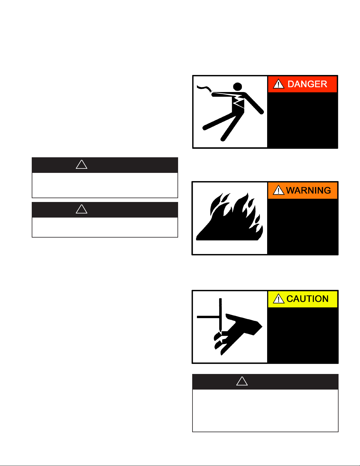
Danger Label
White lettering on a black background except the word
DANGER which is white with a red background.
Electric Shock Hazard.
Turn Off All Power
Before Servicing.
Warning Label
White lettering on a black background except the word
WARNING which is white with an orange background.
Fire Hazard.
Use copper wire only.
Failure to observe
could result in property
damage, bodily injury
or death
The signal words DANGER, WARNING and CAUTION
are used to identify levels of hazard seriousness. The signal word
DANGER is only used on product labels to signify an immedi-
ate hazard. The signal words WARNING and CAUTION will
be used on product labels and throughout this manual and other
manuals that may apply to the product.
DANGER
Immediate hazards which WILL result in severe personal
injury or death.
WARNING
Hazards or unsafe practices which COULD result in severe
personal injury or death.
CAUTION
Hazards or unsafe practices which COULD result in minor
personal injury or product or property damage.
Caution Label
White lettering on a black background except the word
CAUTION which is white with a yellow background.
Cuts and Abrasion
Hazard.
Wear gloves and handle
with care.
Failure to observe could
result in bodily injury.
This unit contains HFC-(R-410A), a azeotropic mixture of
R-32(Diuoromethane)andR-125(Pentauoroethane).Do
Not Vent HFC-(R-410A) to the atmoshpere. The U.S. Clean
Air Act requires the recovery of any residual refrigerant. Do
not use R-22 service equipment or components on R-410A
systems.
!
WARNING
Water to Water Source Heat Pumps IM 1072 / Page 3 of 20
Page 4
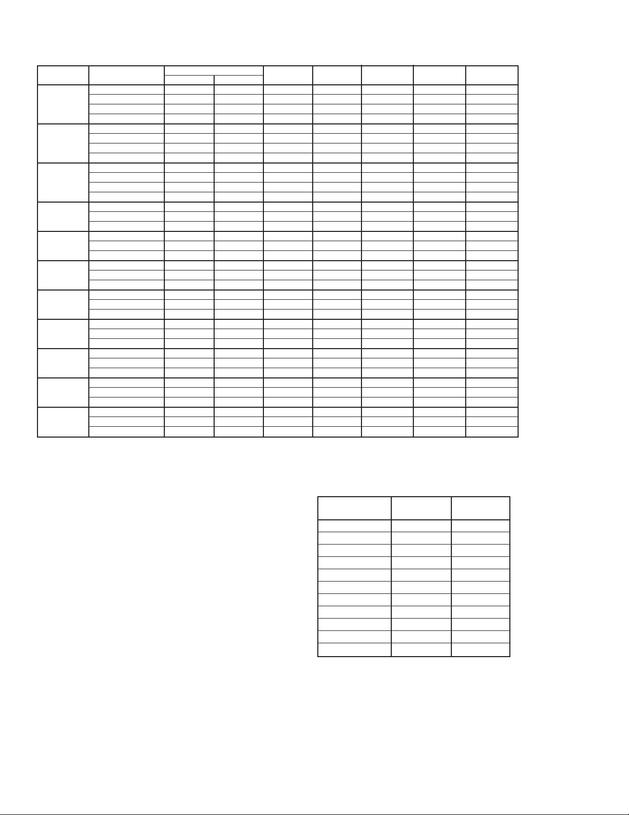
Electrical Data – WRA, WHA, WCA 036 – 420
Unit Size
Compressor Total Min./Max. Min. Circuit Max. Circuit Max. Fuse
036
048
060
072
120
150
180
240
300
360
420
Voltage-Hz-Phase
208-230/60/1
208-230/60/3
460/60/3
575/60/3
208-230/60/1
208-230/60/3
460/60/3
575/60/3
208-230/60/1
208-230/60/3
460/60/3
575/60/3
208-230/60/3
460/60/3
575/60/3
208-230/60/3
460/60/3
575/60/3
208-230/60/3
460/60/3
575/60/3
208-230/60/3
460/60/3
575/60/3
208-230/60/3
460/60/3
575/60/3
208-230/60/3
460/60/3
575/60/3
208-230/60/3
460/50/3
575/60/3
208-230/60/3
460/60/3
575/60/3
RLA (each) LRA (each)
16.7
10.4
5.8
3.8
23.1
16.1
7.1
5.6
30.2
20.6
9.7
7.7
22.5
10.6
7.7
20.1
9.7
7.7
22.5
10.6
7.7
25
12.2
9
30.2
16.7
12.2
48.1
18.6
14.8
51.3
22.5
19.9
55.8
27
23.8
79
73
38
36.5
134
91
46
37
158
155
75
54
149
75
54
155
75
54
149
75
54
164
100
78
225
114
80
245
125
100
300
150
109
340
173
132
Amps Volts Ampacity Breaker Size
16.7
10.4
5.8
3.8
23.1
16.1
7.1
5.6
30.2
20.6
9.7
7.7
22.5
10.6
7.7
40.2
19.4
15.4
45
21.2
15.4
50
24.4
18
60.4
33.4
24.4
96.2
37.2
29.6
102.6
45
39.8
111.6
54
47.6
197/253
187/253
414/506
517/632
197/253
187/253
414/506
517/632
197/253
187/253
414/506
517/632
187/253
414/506
517/632
187/253
414/506
517/632
187/253
414/506
517/632
187/253
414/506
517/632
187/253
414/506
517/632
187/253
414/506
517/632
187/253
414/506
517/632
187/253
414/506
517/632
20.9
13
7.3
4.8
28.9
20.1
8.9
7
37.8
25.8
12.1
9.6
28.1
13.3
9.6
46.4
21.8
17.3
50.6
23.9
17.3
56.3
27.5
20.3
68
37.6
27.5
108.2
41.9
33.3
115.4
50.6
44.8
125.6
60.8
53.6
35
20
15
15
50
35
15
15
60
45
20
15
50
20
15
60
30
25
70
30
25
80
35
25
90
50
35
150
60
45
150
70
60
175
80
70
35
20
15
15
50
35
15
15
60
45
20
15
50
20
15
60
30
25
70
30
25
80
35
25
90
50
35
150
60
45
150
70
60
175
80
70
Capacity Data
Installation
Pre-Installation and Code Requirements
After removing the unit from the carton, immediately remove
the panels and inspect for any damage that might have occurred
during shipment. Report concealed damage immediately to the
transportation company and request inspection.
The electric power source must be the same voltage and
phase as shown on the serial plate. Line and low voltage wiring must be done in accordance with local codes or the national
electric code.
Make a survey of the nal location for the unit before setting
it in place. The unit should be centrally located with respect to
the distribution system. Install the unit within a heated area.
Exposure to inclement weather conditions may cause freeze
damage that is not covered by the warranty.
Heating Cooling
Model
36 48,200 34,300
48 58,200 42,100
60 67,200 46,600
72 85,500 62,200
120 129,000 94,500
150 170,400 122,140
180 237,000 157,000
240 290,900 202,400
300 339,720 221,800
360 416,900 284,700
420 493,200 358,600
Note:
At standard rating conditions of:
Heating - 100°F entering load water, 70°F entering source water.
Cooling - 55°F entering load water, 85°F entering source water.
Page 4 of 20 / IM 1072 Water to Water Source Heat Pumps
Btuh Btuh
Page 5

Installation
Mounting the Unit
The unit should be mounted level on a vibration absorbing
pad slightly larger than the base to provide isolation between
the unit and the oor. It is not necessary to anchor the unit to
the oor.
The electrical connections are accessible from the front. The
compressor can be accessed from either side. A minimum of 24"
clearance in front and sides of the unit should be provided to al-
low sufcient room to make water and electrical connections. If
the unit is located in a conned space such as a closet, provisions
must be made for unit servicing. Unit sizes 036 thru 072 may be
stacked vertically (2 high) in tight mechanical rooms.
Piping the Unit
Both source and load connections must be at least as large
as the unit connection on the unit. The unit may be furnished
with either copper or optional cupronickel coil on either source
or load coaxial heat exchanger. Cupronickel should always be
used when chlorinated water or ground water which is high in
mineral content is the load or source load uid. Never use exible hoses that are smaller (inside diameter) than that of the water
connection on the unit. Make sure hoses and pipes are suitable
for system water pressure and sized for proper ow rate.
The supply and the discharge pipes should be insulated to
prevent condensation damage caused by low water temperature
in the pipes.
If water hammer should occur during start-up or shut down,
slow closing diaphragm type solenoid valves should be used.
Placing the solenoid valve on the outlet side of the system helps
relieve this situation. Due to high pressure drop or poor throttling characteristics, globe and gate valves should not be used,
all ow valves should be ball type.
Domestic Hot Water Heat Recovery
The unit may have an optional factory installed waste heat
recovery feature. The heat recovery device is factory piped to
the refrigerant circuit of the unit. The plumbing to the water
tank and the power to the recovery pump are to be completed
in the eld as required.
Care should be exercised in plumbing water lines to and from
the water heater. Note: It is important that both water lines be
insulated. For run less than 50 feet one way, use 1/2" O.D. water
lines on models sizes 036 thru 072. A run over 50 feet should
be avoided. On models 120 thru 420 specic system data must
be matched to industry standard pipe sizing charts.
To make a connection to Hot Water Heat Recovery:
1. Turn off power or gas valves to the water heater.
2. Turn off water supply to the water heater.
3. Open hot water faucet and drain tank.
4. Connect tubing to “Heat Recovery Water Out” on the unit
and extend this line to the hot water heater. Attach to hot
water heater with ttings.
!
CAUTION
5. Connect tubing to “Heat Recovery Water In” on the unit
and extend this line to the water heater. Attach to cold water
supply. Place pump in this line.
6. Set water heater thermostat as follows:
Electric, Double element - Upper 12 5° F, Lowe r
minimum
Gas, Oil or Single element - 125°F
7. Wire according to single phase diagram (page 12) and three
phase diagram (pages 13 and 14).
8. The piping and wiring are now complete. Turn on water
supply to water heater. With an open hot water faucet, allow tank to ll. Bleed air from water lines. Check for water
leaks. Do not restore power to water heater until after you
have veried that the heat recovery unit is working and you
have hot water circulating back to the water heater. Restore
power to the water heater.
9. On start up of the unit, make the following operation
checks:
■ Pump runs only when the compressor is on. Pump is
turned on by thermostat on compressor discharge
line.
■ All air is purged from water lines.
■ Verify water circulation to and from water heater.
Applications
Cooling Tower/ Boiler Application Closed Loop
Cooling Tower and Boiler Loop System temperature is
usually maintained between 55°F and 90°F. In the cooling
mode, heat is rejected from the unit into the source water loop.
To reject excess heat from the water loop, the use of a closed
circuit evaporative cooler or an open type cooling tower with
a secondary heat exchanger between the tower and the water
loop is recommended. When utilizing open cooling towers
chemical water treatment is mandatory so that the water is free
from corrosive minerals. It is imperative that all air be removed
from the source closed loop side of the heat exchanger to protect
against fouling.
In the heating mode, heat is absorbed from the source water
loop. A boiler can be utilized to maintain the loop at the desired
temperature. In milder climates a “ooded tower” concept is
often used. This concept involves adding makeup water to the
cooling tower sump to maintain the desired loop temperature.
When making water connections to unit sizes 036 thru 072,
a Teon taped thread sealant is recommended to minimize fouling of the pipes. Sweat connections are used for unit sizes 120
thru 420. The water lines should be routed so as not to interfere
with access to the unit. The use of short lengths on high pressure
hose with a swivel type tting may simplify the connections and
prevent vibration transmission to the building.
Before nal connection to the unit, the supply and return
hose kits must be connected together and the system ushed
to remove dirt, piping chips and foreign material. Ball valves
should be installed in the supply and return lines for unit isola-
tion and unit water ow rate balancing. The return valve can
be adjusted to obtain the proper ow rate whenever the unit
heats or cools.
Improperwaterowinthesystemduetopiping,valvingor
improper pump operating will void the warranty.
Water to Water Source Heat Pumps IM 1072 / Page 5 of 20
Water piping exposed to outside may freeze.
!
CAUTION
Page 6

Pressure/temperature ports recommended both supply and
return lines adjacent to the unit for system ow balancing. Flow
can be accurately set by measuring the refrigerant-to-water heat
exchangers water side pressure drop.
Well Water Application Open Loop
Water pressure must be maintained in the heat exchanger by
placing water control valves at the outlet of the unit. A bladder
type expansion tank may be used to maintain pressure on the
system. Pressure/temperature ports should be used to set ow
rates by checking pressure drop across the heat exchanger. Avoid
using low voltage (24 volt) solenoids, using them may overload
the unit transformer or interfere with the lockout impedance
circuit. Line voltage solenoids across the load side of compressor contactor are recommended. Normally residential systems
require about 2-gpm of ow rate per ton of cooling capacity is
needed in open loop systems.
Discharge water from a heat pump is not contaminated in
any manner and can be disposed of in various ways depending
on local building codes.
Disposal methods may be by recharge well, storm sewer,
drain eld, adjacent stream or pond. Most local codes forbid the
use of sanitary sewer for disposal. Consult the local building and
zoning department to determine compliance in your area.
Earth Coupled Application Closed Loop
Earth coupled closed loop systems should follow the same
International Ground Source Heat Pump Association guidelines
used for closed loop heat pump applications. Once piping is
completed between the loop pump kit and the earth loop, nal
purging and charging of the loop is required. A ush/purge
assembly capable of obtaining a velocity of 2 fps throughout
the entire system is required. Usually a pump of at least 1.5 hp
will be adequate to purge air and dirt particles from the loop
itself for most residential systems. Commercial systems must
be sized carefully using pump manufacturer pump curves and
system specic data. Flush the system adequately to remove as
much air as possible then pressurize the loop to a static pressure
of 20 to 30 psi. This is normally adequate for proper system
operation. Check for proper ow through the unit by checking
pressure drop across the heat exchanger and compare it to the
cooling and heating operating pressure tables on page 11. In
order to achieve proper cooling capacity in a earth coupled close
loop application, a rate of 3 gpm per ton is required. Antifreeze
solutions are required when low evaporating conditions are
anticipated. Always use pressure/temperature ports to provide
proper uid ow rates.
Typical Load Side Applications
There are many load side applications for which the uid to
uid liquid chiller heat pumps can be used. The most popular
used would include: Hydronic baseboard heating, hydronic inslab oor heating, forced air fan coil heating or cooling, ice and
snow removal, heating potable water, heating swimming pools
and spas, and process uid heating and cooling. When specify-
ing load side heat transfer surface it is important to consider the
heat pump output capacities and uid ow rates. Insufcient
load side heat transfer surface may cause unstable heat pump
operating. Pressure/temperature ports should always be used
to determine load side ow rates. Avoid contact of dissimilar
metals in the load side piping system.
The units can provide heating or cooling for pools and spas
without the use of a secondary heat exchanger. This application
would however require a cupronickel load side heat exchanger.
Automatic chemical feeders must never be installed upstream of
the heat pump. An external bypass should be installed to avoid
over owing the heat exchanger which could cause erosion.
Proper pool PH levels and chemical balances must be maintained
to avoid possible heat exchanger damage.
Page 6 of 20 / IM 1072 Water to Water Source Heat Pumps
Page 7

Start Up
Check the following before powering the unit.
• Avoid starting any electrical equipment for the rst time
alone, always have another person a safe distance from
the unit that can turn off the main power in the event of an
accident.
• High voltage supply matches the nameplate rating.
• Field wire size, breakers and fuses are the correct size.
• Low voltage control circuit is correct.
• Water piping is complete and correct.
• Closed loop system is ushed and purged.
• Isolation valves are open.
• Loop pumps are correctly wired.
• Access panels are in place and secured.
• Thermostat is in “off” position.
Maintenance Procedures
Proper maintenance is important to provide the most efcient
operation and longest life for your equipment. The following
points are to serve as a general guide. Always consult with your
maintenance contractor with regard to the specic requirements
of your own installation.
Paint Finish
The electrodeposition paint nish may be polished if desired. Spray paint is available in case of accidental scratching
or chipping.
The following should be checked only by a competent
contractor.
Contactor Points
Check contactor points twice a year to see that they are not
burned or pitted as a result of low voltage, lightning strikes, or
other electrical difculties.
Electric Shock Hazard.
Turn Off All Power
Before Servicing.
Check, Test and Start (See Form on page 18)
1. Set thermostat to highest position.
2. Set thermostat switch to “cool”. Compressor should not
operate. The source water pump should energize.
3. Slowly lower the thermostat setting until the compressor is
energized. Regulate the water ow utilizing the P/T plugs
and compare to the performance tables on page 11.
4. Check the cooling refrigerant pressures against valves with
the tables .
5. Turn thermostat switch to the “off” position. The unit will
stop running and the reversing valve should de-energize.
6. Leave unit “off” for approximately ve minutes to allow
pressure to equalize.
7. Adjust thermostat to lowest setting.
8. Set thermostat switch to “heat” position.
9. Slowly adjust thermostat to higher temperature until com-
pressor energizes.
10. Compare the heating refrigerant pressure with valves with
the tables .
11. Check for vibrations, noise, water leaks, etc.
12. Adjust thermostat to correct mode and set to maintain
desired temperature.
13. Instruct the equipment owner/operator of correct thermostat
and system operation.
14. Be certain to complete and forward the warranty papers to
McQuay.
Water System
The water circulating pump should be checked and cleaned,
so that it is operating normally. Clogged coils lead to high head
pressures and inefcient operation. If coil is limed, a cleaning
treatment may be necessary. Water coils should be checked
yearly for liming or clogging.
Improper Unit Functioning
If unit is not performing properly, several readings of temperature, pressure and electrical characteristics need to be taken.
The normal required troubleshooting information is listed on the
Check, Test and Start Form on page 18.
Note: DO NOT place refrigeration gauges on system for
Check, Test and Start procedure. (To be used for major
service only.)
To Installer: Fill out Check, Test and Start Form on page 18
and leave copy with the customer.
Water to Water Source Heat Pumps IM 1072 / Page 7 of 20
Page 8

Dimensional Data – WRA, WCA, WHA – Size 036-072
Dimensions - Size 036
Dimensions (inches) Pipe Sizes (FPT) Connection Sizes
A B C D E F G H J K L M N P Control Electric
Electric Source Hot Water
28⅛ 28⅛ 19 1¾ 6⅜ 3⅞ 2 11⅞ 17⅛ 4 1½ 14⅞ 10⅝ 8⅝ 1/2"KO 3/4"KO 1/2"KO 3/4"FPT 1/2"FPT
Auxiliary Load Domestic
Dimensions - Size 048-060
Dimensions (inches) Pipe Sizes (FPT) Connection Sizes
A B C D E F G H J K L M N P Control Electric
Electric Source Hot Water
28⅛ 28⅛ 21 2¼ 7½ 3⅞ 2 13¾ 19 4 1½ 14⅞ 10⅝ 8⅝ 1/2"KO 3/4"KO 1/2"KO 1"FPT 1/2"FPT
Auxiliary Load Domestic
Dimensions - Size 072
Dimensions (inches) Pipe Sizes (FPT) Connection Sizes
A B C D E F G H J K L M N P Control Electric
Electric Source Hot Water
28⅛ 28⅛ 21 211/16 10⅝ 95/16 2 11½ 19 4 1½ 14⅞ 10⅝ 8⅝ 1/2"KO 3/4"KO 1/2"KO 1"FPT 1/2"FPT
Page 8 of 20 / IM 1072 Water to Water Source Heat Pumps
Auxiliary Load Domestic
Page 9

Dimensional Data – WRA, WCA, WHA – Size 120-180
Dimensions - Size 120-150
Dimensions (inches) Water Connections Size
A B C D E F G H K L M N P Q R S
26¼ 19½ 12¼ 4½ 8⅜ 22¼ 4⅜ 18¾ 41 22⅛ 34 1 113/16 37 29¾ 42 1½"
Load Source FPT
Dimensions - Size 180
Dimensions (inches) Water Connections Size
A B C D E F G H K L M N P Q R S
26¼ 19½ 12¼ 4½ 8⅜ 22¼ 4⅜ 18¾ 41 22⅛ 34 1 113/16 37 29¾ 42 2"
Water to Water Source Heat Pumps IM 1072 / Page 9 of 20
Load Source FPT
Page 10

Dimensional Data – WRA, WCA, WHA – Size 240-420
Dimensions - Size 240-420
Dimensions (inches) Water Connections Size
A B C D E F K L M N P Q R S
31 20⅞ 16½ 4⅞ 22½ 27½ 63⅛ 22⅛ 34 1 113/16 52⅛ 44⅛ 50 2"
Page 10 of 20 / IM 1072 Water to Water Source Heat Pumps
Load Source FPT
Page 11

Physical Data – WRA, WCA, WHA 036 – 420
Unit Size
Nominal
036
048
060
072
120
150
180
240
300
360
420
Cooling Mode Operating Pressures (PSIG)
WRA and WCA Models
Leaving
Load °F
45 90–109 210–250 95–110 270–310 98–115 355–395
50 97–114 215–255 100–115 280–315 105–123 365–410
55 106–123 220–265 110–125 285–320 118–135 385–420
Heating Mode Operating Pressures (PSIG)
WRA and WHA Models
100 66–90 375–410 90–114 398–435 120–143 420–455 145–170 445–490
120 66–90 503–542 92–115 515–556 123–145 530–570 153–175 555–600
Entering
Load °F
80 63–87 275–318 85–110 295–332 115–138 325–365 138–162 365–400
BTUH
Cooling
36,000
48,000
60,000
72,000
120,000
150,000
180,000
240,000
300,000
360,000
420,000
Cabinet Cabinet Cabinet
Width
28.125
28.125
28.125
35.125
34.00
34.00
34.00
34.00
34.00
34.00
34.00
Depth
28.125
28.125
28.125
28.125
42.00
42.00
42.00
50.00
50.00
50.00
50.00
Height
19.00
21.00
21.00
21.00
41.00
41.00
41.00
63.13
63.125
63.125
63.125
Operating Shipping
Weight lbs. Weight lbs.
250
297
302
320
570
735
900
1040
1130
1420
1620
259
300
305
370
610
770
950
1140
1230
1540
1750
Entering Source Temperature °F
50 70 90
Suction Discharge Suction Discharge Suction Discharge
Entering Source Temperature °F
30 50 70 90
Suction Discharge Suction Discharge Suction Discharge
Refrigeration
Charge
2.80
3.50
4.40
5.00
2.75
4.25
8.00
10.00
16.00
17.50
20.00
Water Connection
FPT
.75
1.00
1.00
1.00
1.50
1.50
1.50
2.00
2.00
2.00
2.00
Antifreeze Correction Factors (Load Side)
Ethylene Glycol
Cooling Capacity 0.9950 0.9920 0.9870 0.9830 0.9790
Heating Capacity 0.9910 0.9820 0.9770 0.9690 0.9610
Pressure Drop 1.0700 1.1300 1.1800 1.2600 1.2800
Propylene Glycol
10% 20% 30% 40% 50%
Cooling Capacity 0.9900 0.9800 0.9700 0.9600 0.9500
Heating Capacity 0.9870 0.9750 0.9620 0.9420 0.9300
Pressure Drop 1.0700 1.1500 1.2500 1.3700 1.4200
Note:
Manufacturer recommends maximum glycol mixture not to exceed 25%
Methanol
10% 20% 30% 40% 50%
Cooling Capacity 0.9980 0.9720 – – –
Heating Capacity 0.9950 0.9700 – – –
Pressure Drop 1.0230 1.0570 – – –
Ethanol
10% 20% 30% 40% 50%
Cooling Capacity 0.9910 0.9510 – – –
Heating Capacity 0.9950 0.9600 – – –
Pressure Drop 1.0350 0.9600 – – –
10% 20% 30% 40% 50%
Water to Water Source Heat Pumps IM 1072 / Page 11 of 20
Page 12

Wiring Diagram – 208-230/60/1 Phase, unit Sizes 036, 048, 060
and 072
Page 12 of 20 / IM 1072 Water to Water Source Heat Pumps
Page 13

Wiring Diagram – 3 Phase, Unit Sizes 036, 048, 060 and 072
Water to Water Source Heat Pumps IM 1072 / Page 13 of 20
Page 14

Wiring Diagram – 3 Phase, Unit Sizes 120, 150, 180, 240, 300, 360
and 420
Page 14 of 20 / IM 1072 Water to Water Source Heat Pumps
Page 15

WHA Circuit Diagram
WHA
Load Coil = Heater-Condenser
Source Coil = Evaporator
Water to Water Source Heat Pumps IM 1072 / Page 15 of 20
Page 16

WRA Circuit Diagram
WRA
Reverse Cycle
No Domestic Hot Water
WRA
Reverse Cycle
With Domestic Hot Water H.R. Coil
Page 16 of 20 / IM 1072 Water to Water Source Heat Pumps
Page 17

WCA Circuit Diagram
WCA
Load Coil = Chiller-Evaporator
Source Coil = Condenser
No Domestic Hot Water
WCA
Load Coil = Chiller-Evaporator
Source Coil = Condenser
With Domestic Hot Water H.R. Coil
Water to Water Source Heat Pumps IM 1072 / Page 17 of 20
Page 18

Check, Test and Start Form
General Information
Customer Name ____________________________________ Dealer Name ______________________________________
Address ___________________________________________ Address __________________________________________
__________________________________________________ _________________________________________________
__________________________________________________ _________________________________________________
Phone # ___________________________________________ Phone # __________________________________________
Product Information
Unit Model # ____________________________________________________________
Unit Serial # _____________________________________________________________
Source Coil Application Ground Source Open Well Other _________________
Load Coil Application Fan Coil Unit Radiant Htg/Clg Coils Baseboard Radiation
Other _____________________________________________
Voltage _____________ Amperage ________________ Phase ________________ Transformer Volts _______________
Unit Function
HEATING (WRA & WHA) ENTERING LEAVING DIFF (TD)
Load Liquid Temperature, °F
From fan coil unit, radiant coils,
baseboard radiation, etc. _________________ _________________ ________________
Source Liquid Temperature, °F
From well, geothermal closed loop,
plate heat exchanger, etc. _________________ _________________ ________________
COOLING (WRA & WCA)
Load Liquid Temperature, °F
To fan coil unit, radiant coils,
baseboard radiation, etc. _________________ _________________ ________________
Source Liquid Temperature, °F
From well, geothermal closed loop,
plate heat exchanger, etc. _________________ _________________ ________________
Load Fluid Pressure FT. HD or PSIG
[Note 1 PSIG = 2.31 FT. HD] _________________ ________________ _________________
Source Fluid Pressure _________________ ________________ _________________
Load GPM ____________________ Source GPM __________________
Source Fluid Water Anti-freeze
HA or HR = 500 x TD x GPM For Anti-Freeze solution = 485 x TD x GPM
Calculation __________ x __________ x __________ = ________________
(Load) 500 or 485 TD GPM HA or HR
Check product performance tables on page 11 to determine if calculation is within 10% of table value.
Page 18 of 20 / IM 1072 Water to Water Source Heat Pumps
Page 19

General Service Guide
All models employ an electromechanical control system for maximum reliability.
Symptom Possible Trouble Method of Finding
1. Noisy Operation. a. Chattering contactor noise. a. Check contactor points, check for adequate control
voltage from transformer, and check control circuit
for shorts or breaks, check thermostat.
2. Compressor will a. Lock Out Relay Open. a. Turn thermostat off, then on.
not start.
b. Loose electrical connections. b. Check all connections at contactor and compressor
terminal box for loose or burned connection on terminal.
c. Refrigerant charge lost, low pressure c. Check for R-410A pressure.
cutout open.
d. No control voltage to the compressor d. Check for 24 volts across contactor coil.
contactor. If no voltage, check for thermostat circuit trouble
or for compressor safety controls open.
e. Contactor pulled in, but compressor still e. Check compressor overload circuit, contactor points, etc.
won’t start.
3. Compressor starts but a. Run capacitor could be bad. a. Check capacitor.
hums and trips out
on overload. b. Voltage may be low. b. Check it.
c. Seized bearings on compressor. c. Replace compressor.
4. Compressor starts but a. Lowliquidow(heatingcycle). a. Checkliquidow.
cuts out on low
pressure control. b. Low refrigerant charge. b. Remove refrigerant, repair leak and recharge.
c. Restriction in liquid refrigerant line. c. Check pressures and look for frosting across
the restriction.
d. Lowairow(coolingcycle). d. Checkandcorrect.
e. Low pressure cutout may have incorrect e. Check low pressure cutout for correct pressure.
pressure function.
5. Compressor starts a. Condenser coils limed or restricted. a. Check it. (Open systems)
but cuts out on high
pressure control. b. Malfunctioning high pressure control. b. Check that the control is cutting out at the correct
pressure.
c. Reducedorlackofliquidow. c. Checkliquid.
d. Reducedevaporatorairow d. Checkairow.
(heating cycle).
6. Compressor runs on a. Reversing valve may be defective. a. See that it has shifted.
heating cycle,
but does not heat. b. Thermostat may be defective. b. Check wiring diagram.
Water to Water Source Heat Pumps IM 1072 / Page 19 of 20
Page 20

Replacement Parts List
# Description 036 048 060 072 120 150 180 240 300 360 420
1 Expansion Valve* 564-672 564-672 564-670 546-671 564-670 564-671 561-664 564-673 564-676 564-676 564-676
2 Contactor 841-040 841-040 841-040 841-040 841-039 841-039 841-072 841-072 841-072 841-155 841-162
3 Reversing Valve 564-677 564-508 564-609 564-508 564-508 564-608 564-608 564-574 564-574 564-589 564-589
4 Microprocessor 872-089 872-089 872-089 872-089 872-089 872-089 872-089 872-089 872-089 872-089 872-089
5
6 High Pressure
7
8
8
10
11
12
13
*Where same valve is used in two or more units superheat settings may differ. Consult factory for valve with correct setting.
(Compressor)
Board (comp ctrl)
Capacitor
(Compressor)
Switch (HP)
Low Pressure
Switch (LP1)
Fluid/Refrigerant
Coil S/W Copper
Fluid/Refrigerant
Coil S/W CU-NI
9 Transformer 846-056 846-056 846-056 846-056 846-129 846-129 846-129 846-129 846-129 846-129 846-129
Low pressure
switch (LP2)
230/3
Compressor
Reversing Valve
Coil
Refrigerant
Charge R-410A lb.
841-039 841-039 841-039 841-039 841-021
(1) (1) (1) (1) (2)
844-142 844-142 844-142 844-142 844-142 844-142 844-142 844-142 844-142 844-142 844-142
844-151 844-151 844-151 844-151 844-151 844-151 844-151 844-151 844-151 844-151 844-151
512-200 512-201 512-201 512-259 512-201 512-202 512-200 512-201 512-202 512-201 512-202
512-200 512-201 512-201 512-259 512-201 512-202 512-200 512-201 512-202 512-201 512-202
844-150 844-150 844-150 844-150 844-150 844-150 844-150 844-150 844-150 844-150 844-150
800-840 800-805 800-820 800-803 800-821 800-804 800-800 800-812 800-1014 800-814 800-914
874-209 874-209 874-209 874-209 874-209 874-209 874-209 874-209 874-209 874-209 874-209
(1) (1) (1) (1) (2)
2.8 3.5 4.4 5 5.5 8.5 16 20 32 35 40
841-021 841-039 841-039 841-039 841-072 841-065
(2)
(2)
(2)
(2)
(2)
(2)
(2)
(2)
(2)
(2)
(2)
(2)
4900 Technology Park Boulevard • Auburn, New York 13021-9030 • 1.800.432.1342 • USA IM 1072 / Page 20 of 20 (3-10)
©2010 McQuay International
 Loading...