

Page 1
Installation & Maintenance Manual
Vertical Stack Water Source Heat Pumps
Model VHC Vertical Stack Chassis
Model VHF Vertical Stack Cabinet
Unit Sizes 009 – 036 / R-410A Refrigerant
IM 986-2
Group: WSHP
Part Number: 669646403
Date: May 2012
©2012 McQuay International • 800.432.1342 • www.daikinmcquay.com
Page 2

Page 2 of 48 / IM 986-2
Page 3

Table of Contents
Model Nomenclature ............................ 4-5
Vertical Stack Model VHF (Cabinet)...............4
Vertical Stack Model VHC (Chassis)...............5
Receiving, Storage & Handling ................... 6-7
Disassembling Upper & Lower Cabinet Sections..... 7-8
Dimensional Data .............................. 9-10
Unit Size 009-018 ..............................9
Unit Size 021-036 .............................10
Pre-Installation Considerations ....................11
Cabinet Configurations...........................12
Typical Framing & Discharge Arrangements.........13
Critical Dimensions ..............................14
Framing Locations to Unit Openings..............14
Vertical Riser Stub-Outs Locations to
Unit Knockouts...............................14
Return Air Grille/Panel Dimensions...............15
Installation Procedure.........................16-26
Risers & Cabinet........................... 16-17
Cleaning & Flushing Water System............ 17-19
Power Wiring From Building to Unit...........19-20
Connect Condensate Drain Hose to Drain Stubout ...20
Water Connections ......................... 20-21
Installing Unit Chassis .........................22
Making Cabinet to Chassis Wiring Connections . . . . . 22
Installing & Wiring the Remote Control Node ......23
Installing the Return Air Grille/Panel..............24
Installing the Discharge Air Diffuser ..............25
Twin Units Installation .........................26
Controls..................................... 27-34
MicroTech III Unit Controller ................... 27
Remote Reset Feature ..........................27
MicroTech III Controller Terminal Locations
& Descriptions ............................ 28-29
I/O Expansion Module .........................30
MicroTech III Controller with Lon Module.........31
MicroTech III Controller with BACnet Module .. 32-33
MicroTech III Controller with Lon Module on
Board Diagram ...............................34
Typical Wiring Diagrams ...................... 35-38
MicroTech III Unit Controller, 2-Speed Fan (Toggle or
Thermostat), PSC Motor 208-230/60Hz/1-Phase,
Unit Sizes 009-018............................35
MicroTech III Unit Controller, 2-Speed Fan (Toggle or
Thermostat), PSC Motor 265-277/60Hz/1-Phase,
Unit Sizes 009-036............................36
MicroTech III Unit Controller, 2-Speed Fan (Toggle or
Thermostat), X13 Motor 208-230/60Hz/1-Phase,
Unit Sizes 021-036............................37
MicroTech III Unit Controller, 2-Speed Fan (Toggle or
Thermostat), X13 Motor 265-277/60Hz/1-Phase,
Unit Sizes 021-036............................38
Start-up........................................39
Additional Accessories (General) ................ 39-43
Thermostats & Temperature Sensors ........... 39-43
Troubleshooting .............................. 44-47
The in and outs of R-410A ......................44
Refrigeration Circuit...........................45
The Water Source Heat Pump Unit ...............46
General Use & Information .....................47
IM 986-2 / Page 3 of 48
Page 4
Model Nomenclature
Vertical Stack Water Source Heat Pump – Cabinet (VHF)
W VHF 1 009 B E DP LRY F 12 S 088
Product
Category
W - WSHP
Product Code
VHF - Cabinet
Design Series
1
2
Unit Size - Tons
009 - 3/4 Ton
012 - 1 Ton
015 - 1-1/4 Ton
018 - 1-1/2 Ton
021 - 1-3/4 Ton
024 - 2 Ton
030 - 2-1/2 Ton
036 - 3 Ton
Controls
B - MicroTech III
C - MicroTech III With LonWorks
D - MicroTech III With BACnet
Voltage
A - 115/60/1 ph
E - 208-230/60/1 ph
J - 265-277/60/1 ph
Secondary Drain Pan
GL - Standard Galvanized Steel
SS - Stainless Steel
Cabinet Type
080 - 80" Cabinet Height
088 - 88" Cabinet Height
092 - 92" Cabinet Height
096 - 96" Cabinet Height
Filter Option
S - Standard 1" Throwaway
P - 2" Pleated (Merv 7)
Y - None
Blower Motor
12 - 2-Speed PSC Motor
32 - ECM 2-speed 2.3 Motor
33 - ECM 2-speed X13 Motor
Power Connection
F - Fused Disconnect
N - Non-Fused Disconnect
H - HACR Breaker
Supply Air Conguration
LYY - Single Supply Outlet, Left Side
RYY - Single Supply Outlet, Right Side
FYY - Single Supply Outlet, Front Side
BYY - Single Back Side Supply Outlet
TYY - Single Top Supply Outlet
LFY - Double Supply, Left Side and Front Side
LRY - Double Supply, Left Side and Right Side
LBY - Double Supply, Left Side and Back Side
RFY - Double Supply, Right Side and Front Side
RBY - Double Supply, Right Side and Back Side
BFY - Double Supply, Back Side and Front Side
LTY - Double Supply, Left Side and Top
RTY - Double Supply, Right Side and Top
BTY - Double Supply, Back Side and Top
FTY - Double Supply, Front Side and Top
LFT - Triple Supply, Left Side, Front Side and Top
LRT - Triple Supply, Left Side, Right Side and Top
FRT - Triple Supply, Front Side, Right Side and Top
FBT - Triple Supply, Front Side, Back Side and Top
BRT - Triple Supply, Back Side, Right Side and Top
BLT - Triple Supply, Back Side, Left Side and Top
YYY - Closed Supply Plenum for eld modication
Page 4 of 48 / IM 986-2
Note: For illustration purposes only. Not all options avail-
able with all models.
Please consult McQuay Sales Representative for
specic availability.
Page 5

Model Nomenclature
Vertical Stack Water Source Heat Pump – Chassis (VHC)
W VHC 1 012 B E A C AMY C
Product
Category
W - WSHP
Product Code
VHC - Chassis
Design Series
1
2
Unit Size - Tons
009 - 3/4 Ton
012 - 1 Ton
015 - 1-1/ 4 Ton
018 - 1-1/2 Ton
021 - 1-3/4 Ton
024 - 2 Ton
030 - 2-1/2 Ton
036 - 3 Ton
Controls
B - MicroTech III
C - MicroTech III With L
D - MicroTech III With BACnet
onWorks
Voltage
A - 115/60/1 ph
E - 208-230/60/1 ph
J - 265-277/60/1 ph
Coax Coil Construction
C - Copper Inner - Steel Outer
S - CuproNickel Inner - Steel Outer
X - Special
Chassis Construction
AYY - Standard Fiberglass Insulation
EYY - IAQ - Cellular Insulation
AMY - Standard w/Compressor Blanket
EMY - IAQ w/Compressor Blanket
AYC - Standard w/E-Coated Air Coil
EYC - IAQ - Cellular w/E-Coated Air Coil
AMC - Standard w/Comp Blanket and Coated Air Coil
EMC - IAQ w/Comp Blanket and Coated Air Coil
Motorized 2-Way Isolation Valve
C - 2-Way Motorized 1/2" Iso-Valve, General Close-Off Pressure N.C.
(Normally Closed)
V - 2-Way Motorized 1/2" Iso-Valve, General Close-Off Pressure N.O.
(Normally Open)
H - 2-Way Motorized 1/2" Iso-Valve, High Close-Off Pressure N.C.
(Normally Closed)
D - 2-Way Motorized 3/4" Iso-Valve, General Close-Off Pressure N.C.
(Normally Closed)
K - 2-Way Motorized 3/4" Iso-Valve, General Close-Off Pressure N.O.
(Normally Open)
J - 2-Way Motorized 3/4" Iso-Valve, High Close-Off Pressure N.C.
(Normally Closed)
Y - None
X - Special
Refrigerant
A - R-410A
X - Special
Note: For illustration purposes only. Not all options
available with all models.
Please consult McQuay Sales Representative
for specic availability.
IM 986-2 / Page 5 of 48
Page 6
Receiving and Storage
Upon receipt of the equipment, check the carton and
pallets for visible damage. Make a notation on the
shipper’s delivery ticket before signing. If there is any
evidence of rough handling, immediately open the
cartons to check for concealed damage. If any damage
is found, notify the carrier within 48 hours to establish
your claim and request their inspection and a report.
The Warranty Claims Department should then be
contacted.
IMPORTANT
This product was carefully packed and thoroughly
inspected before leaving the factory. Responsibility for its
safe delivery was assumed by the carrier upon acceptance
of the shipment. Claims for loss or damage sustained in
transit must therefore be made upon the carrier as follows:
VISIBLE LOSS OR DAMAGE
Any external evidence of loss or damage must be noted
on the freight bill or carrier’s receipt, and signed by the
carrier’s agent. Failure to adequately describe such
external evidence of loss or damage may result in the
carrier’s refusal to honor a damage claim. The form
required to le such a claim will be supplied by the carrier.
CONCEALED LOSS OR DAMAGE
Concealed loss or damage means loss or damage which
does not become apparent until the product has been
unpacked. The contents may be damaged in transit due
to rough handling even though the carton may not show
external damages. When the damage is discovered upon
unpacking, make a written request for inspection by the
carrier’s agent within fteen (15) days of the delivery date
and le a claim with the carrier.
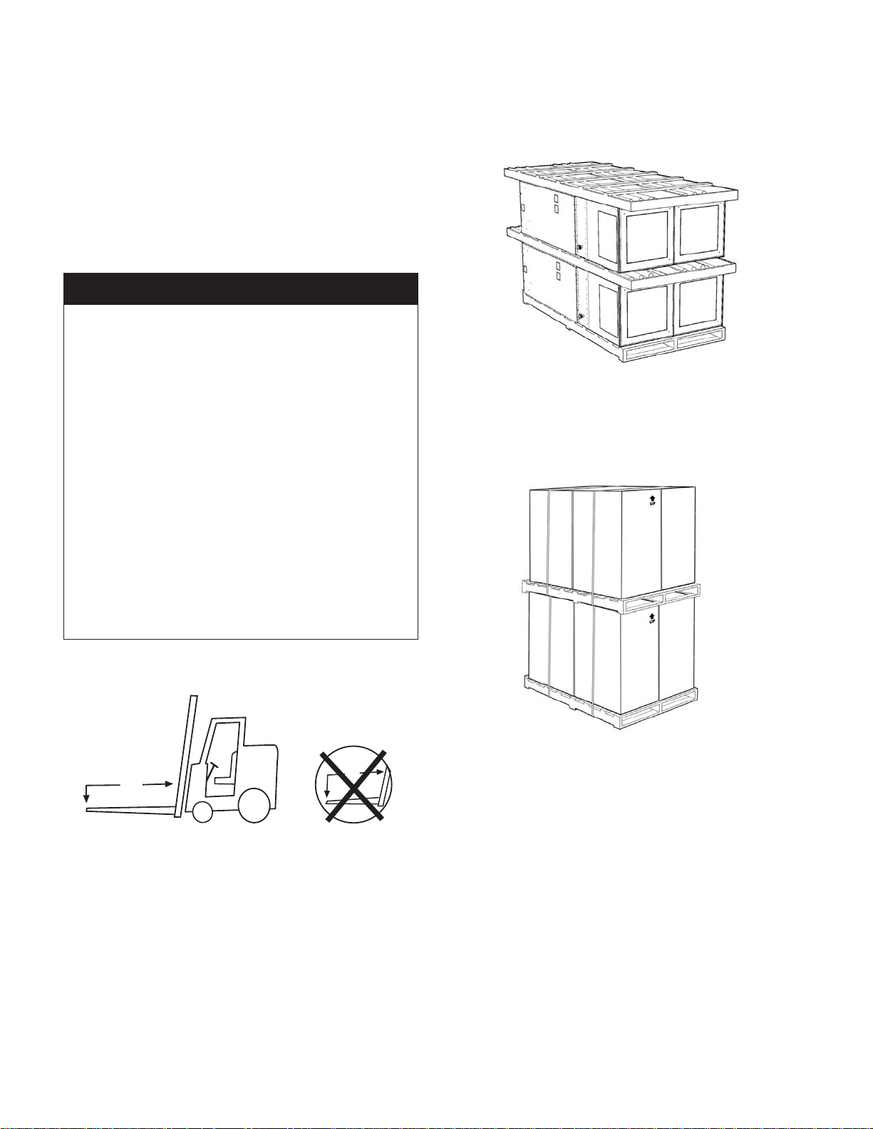
Cabinet Skid (4-units per skid)
Never stack cabinets higher than as illustrated in Figure
1 at any time during transportation or storage or damage
may occur.
Figure 1: Unit Cabinet Skid as Shipped and Stored
Chassis Skid (4 per skid, stored two skids high)
Never stack chassis´ higher than as illustrated in Figure
2 at any time during transportation or storage or damage
may occur.
Figure 2: Chassis Skids Stacked 2 High Maximum
For storing, each carton is marked with “up” arrows.
4'
6'
Storage and Operating Environment
Temporary storage at the job site must be indoor,
completely sheltered from rain, snow, etc. High or low
temperatures naturally associated with weather patterns
will not harm the units. Excessively high temperatures,
140°F (60°C) and higher, may deteriorate certain plastic
materials and cause permanent damage.
Storage Temperature:
-40ºF (-40ºC) to 140ºF (60ºC)
Operating Temperature:
32ºF (0ºC) to 140ºF (60ºC)
Humidity:
10%RH to 90%RH Non-condensing
PCB Material and Flammability Rating:
IPC/ANSI FR or CEM material as required to meet UL
94V-0 ammability rating.
Page 6 of 48 / IM 986-2
Page 7
Handling
Carefully check items against the bills of lading to
verify all crates and cartons have been received.
Cabinets and Chassis normally ship four to a pallet.
Carefully inspect all units for shipping damage. Report
damage immediately to the carrier and le a claim.
Check the unit data plate to be sure the unit electrical
agrees with the power supply available (Figures 3).
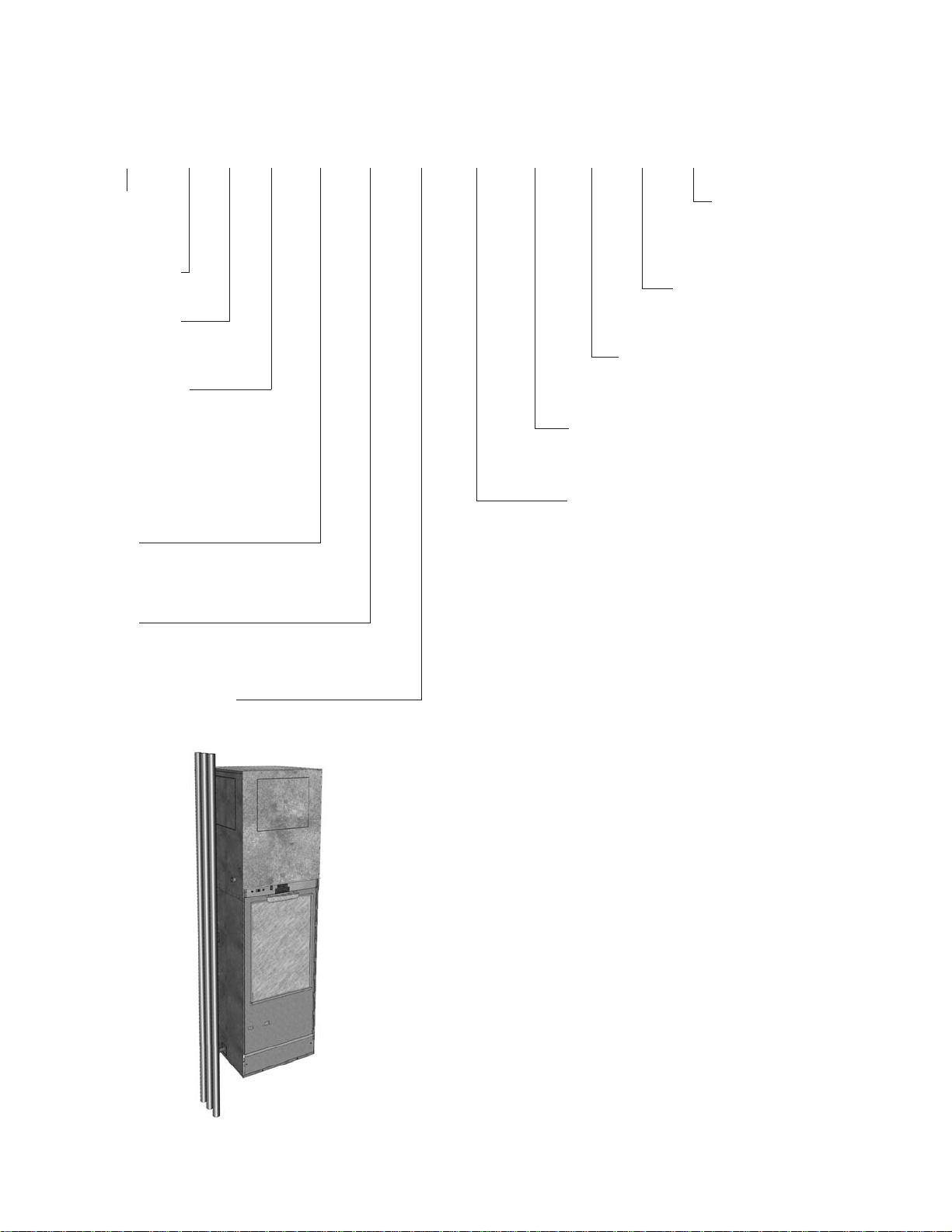
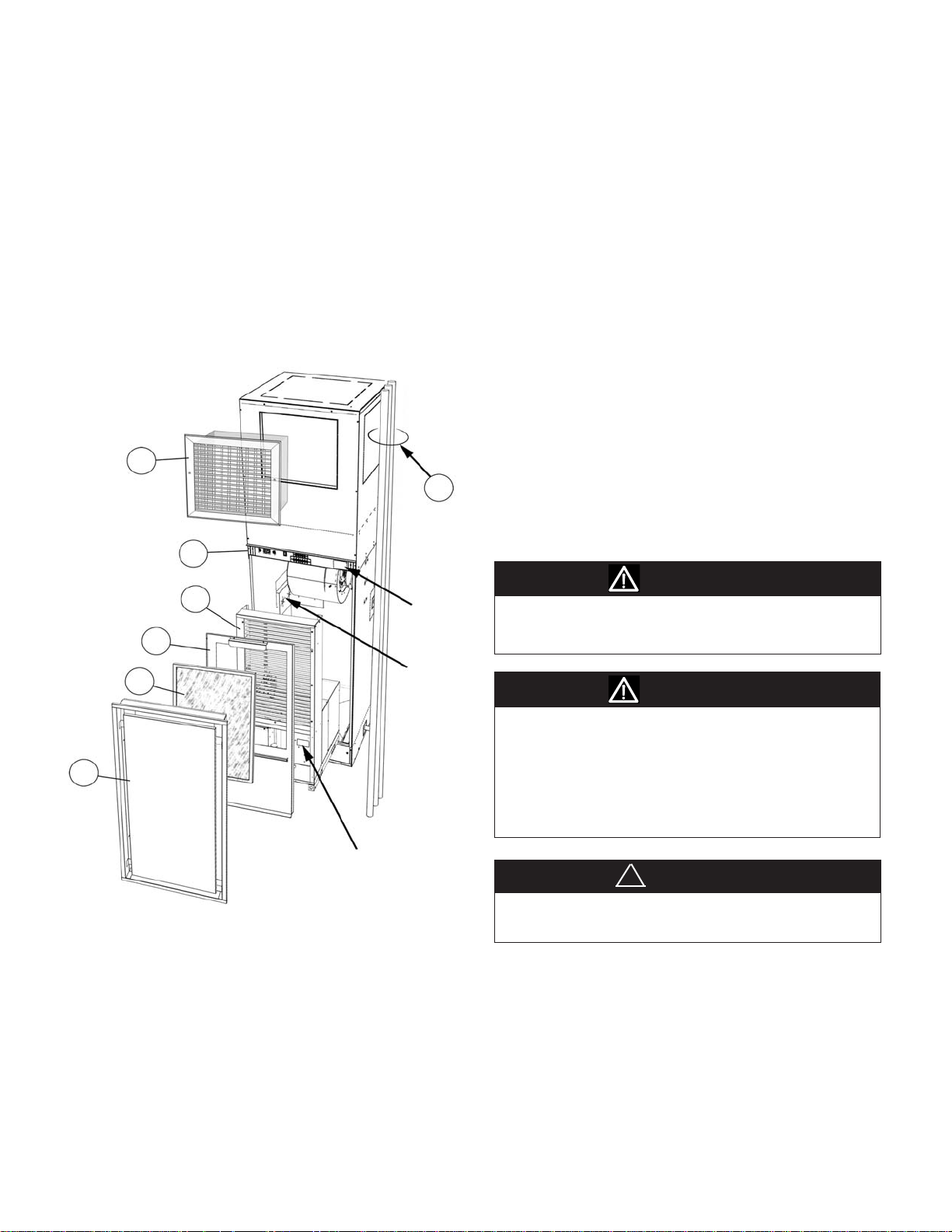
Figure 3: Unit Components & Descriptions - Received as
Assembled Cabinet with Chassis Shipped Separate
4
1a
1
2
1b
1b
3
Unit
Data Plate
Stub-out
Seals
DO NOT handle units by the riser piping. Riser clamps
hold the riser in position; they are not designed to
support the cabinet weight. The clamps are removed
after the unit is installed.
Unit cabinets are factory assembled and wired and
have individual thermostat control capability. They are
installed by stacking one unit on top of the other. While
installing, prevent dirt and other foreign matter from
entering the risers and plugging lines or valves. See
"Cleaning & Flushing Water System" on page 16.
General Information
McQuay Vertical Stack units are designed for use in
multiple oor apartments, ofce buildings, hotels,
nursing homes and other similar applications. They
require a minimum amount of oor space and are
designed for multiple discharge arrangement.
Installation and maintenance must follow accepted
industry practices as described in the ASHRAE
Handbook, the National Electric Code, and other
applicable standards. Install this equipment in
accordance with regulations of authorities having
jurisdiction and with all applicable codes.
WARNING
Installation and maintenance are to be performed by
qualied personnel who are familiar with local codes and
regulations, and experienced with this type of equipment.
WARNING
The installer must determine and follow all applicable
codes and regulations. This equipment presents hazards
of electricity, rotating parts, sharp edges, heat and weight.
Failure to read and follow these instructions can result in
property damage, severe personal injury or death. This
equipment must be installed by experienced, trained
personnel only.
Chassis
Data Plate
Component Descriptions (Assembled
Cabinet)
1. Cabinet assembly complete (without chassis)
1a. Pipe riser sets (inlet, outlet and condensate)
1b. Inner front panel and lter bracket
2. Cooling and heating chassis (shipped separate)
3. Return air grille/panel (accessory)
4. Double-deection diffuser (accessory)
!
CAUTION
Sharp metal edges are a hazard, use care when servicing
to avoid contact with them.
IM 986-2 / Page 7 of 48
Page 8
Disassembling Upper and Lower
Cabinet Sections
The Vertical Stack unit cabinet ships completely
assembled. If required, it may be disassembled into two
(2) sections (upper-fan/discharge cabinet) and (lower
chassis/return air cabinet) to make it easier to handle. To
disassemble, do the following.
1. Remove risers (if received attached).
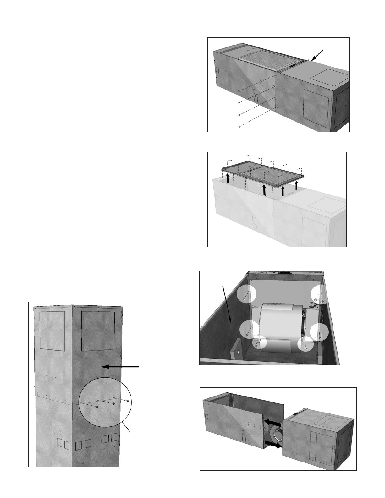
2. Remove the three (bottom row) screws on the back
of the unit as shown in Figure 4.
Note: Retain all screws for later use to reassemble
unit in reverse order as described in steps 1-7.
Number of screws will vary depending on unit size.
3. Carefully lay the unit down on its back and remove
the remaining eight (8) screws on the left and right
side of the cabinet (Figure 5).
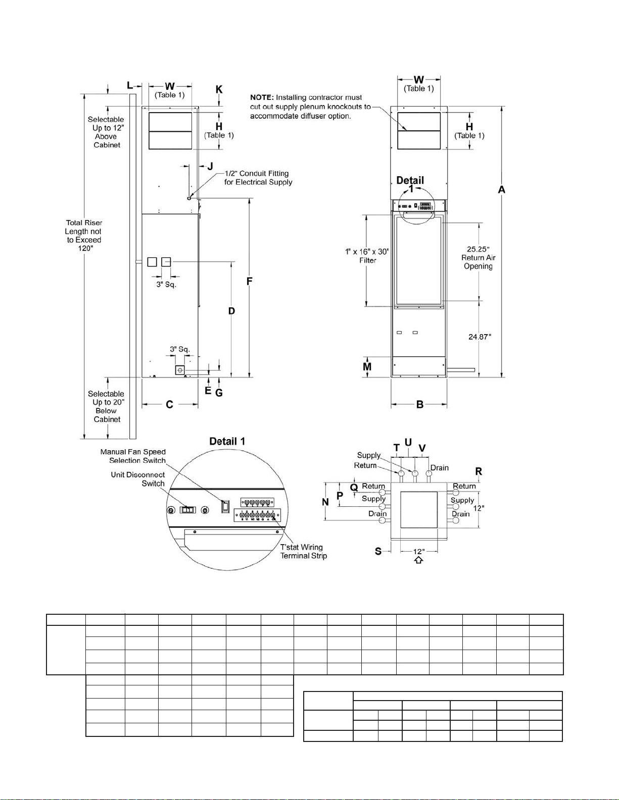
5. Remove the ten (10) screws and lift off the front
panel/lter rack to gain access to the cabinet interior
(Figure 6).
Figure 5: Remove remaining eight (8) screws on the left and
right sides of the cabinet
Four (4) screws located
on left side of cabinet
Figure 6: Remove the ten (10) screws from the front panel/
lter rack.
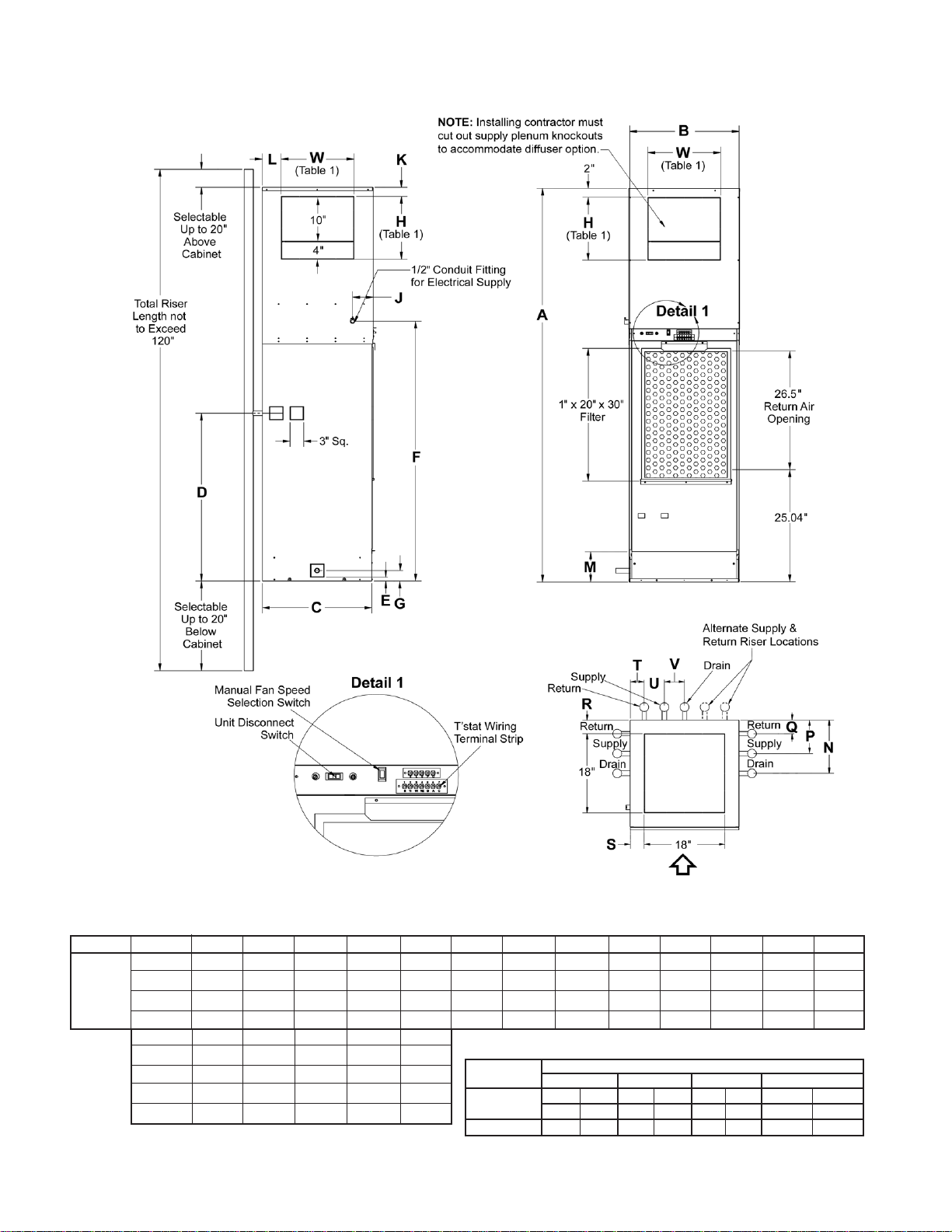
6. Locate and remove the six (6) screws located inside
the cabinet joining the upper and lower cabinet
sections (Figure 7).
Note: Pull the insulaton away from the walls of the
cabinet interior to get access to the screws.
7. Separate the lower return air cabinet section from
the upper blower/discharge cabinet section
(Figure 8).
Figure 4: Remove three (3) screws (bottom row) on the back
of the unit.
Back of Unit
Figure 7: Remove the six (6) screws located on the interior
of the unit.
Return air cabinet
section interior
Figure 8: Separate the lower cabinet section from the upper
cabinet
Page 8 of 48 / IM 986-2
Three screws (bottom row)
Page 9
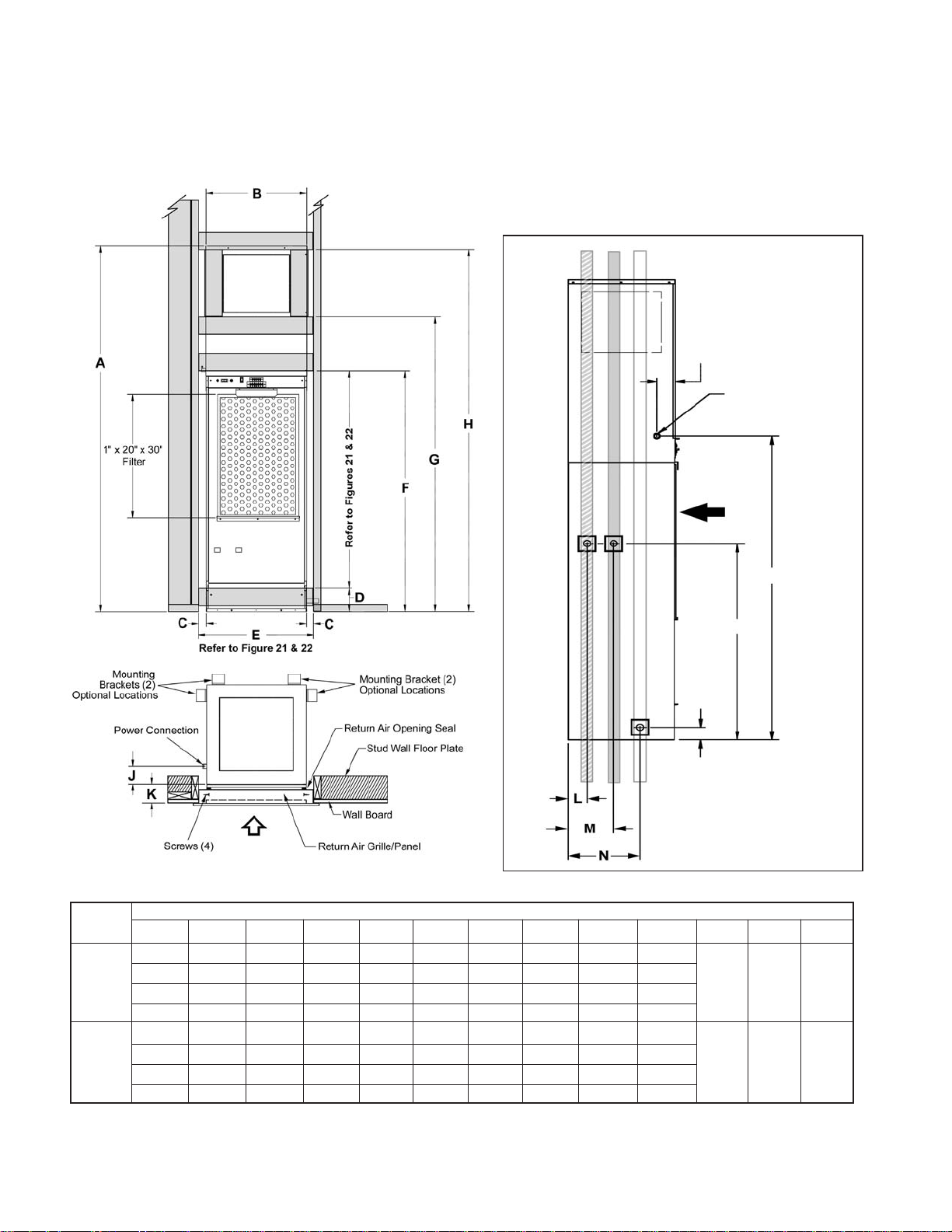
Dimensional Data
Figure 9: Model VHC/VHF – 18" × 18" Cabinet – Size 009-018
Left Side View
Front View
Top View
Dimensions
80" 18.07" 18.11" 37.50" .88" 58.09" 2.38" 3.125" 2" 2" 6.72" 12.4" 7.9" 3.3"
Unit Size
009–018
18" × 18"
Cabinet
A B C D E F G J K L M N P Q
88" 18.07" 18.11" 37.50" .88" 58.09" 2.38" 3.125" 2" 2" 6.72" 12.4" 7.9" 3.3"
92" 18.07" 18.11" 37.50" .88" 58.09" 2.38" 3.125" 2" 2" 6.72" 12.4" 7.9" 3.3"
96" 18.07" 18.11" 37.50" .88" 58.09"
A R S T U V
80" 3" 3" 3.3" 4.5" 4.5"
88" 3" 3" 3.3" 4.5" 4.5"
92" 3" 3" 3.3" 4.5" 4.5"
96" 3" 3" 3.3" 4.5" 4.5"
2.38" 3.125"
Table 1.
Discharge Openings
Unit Size
W H W H W H W H
009 – 012
015 – 018
2" 2" 6.72" 12.4" 7.9" 3.3"
Single Double Triple Single-Top Opening
14" 16" 14" 8" NR NR 12" 12"
14" 16" 14" 8" 14" 8" 12" 12"
NR = Not Recommended
IM 986-2 / Page 9 of 48
Page 10
Dimensional Data
Figure 10: Model VHC/VHF – 24" × 24" Cabinet – Size 021-036
Front View
Left Side View
Top View
Dimensions
Unit Size
80" 24" 24.04" 37.50" .88" 58.08" 2.38" 4.54" 2" 3" 6.72" 12.13" 7.63" 3.13"
A B C D E F G J K L M N P Q
021–036
88" 24" 24.04" 37.50" .88" 58.08" 2.38" 4.54" 2" 3" 6.72" 12.13" 7.63" 3.13"
24" × 24"
92" 24" 24.04" 37.50" .88" 58.08" 2.38" 4.54" 2" 3" 6.72" 12.13 7.63" 3.13"
Cabinet
96"
A R S T U V
80" 3.09" 3.10" 3.12" 4.50" 4.50"
88" 3.09" 3.10" 3.12" 4.50" 4.50"
92" 3.09" 3.10" 3.12" 4.50" 4.50"
96" 3.09" 3.10" 3.12" 4.50" 4.50"
24" 24.04"
37.50" .88" 58.08"
2.38" 4.54"
2" 3" 6.72" 12.13" 7.63" 3.13"
Table 1.
Discharge Openings
Unit Size
W H W H W H W H
021 – 024
030 – 036
Single Double Triple Single-Top Opening
NR NR 18" 10" 18" 10" 18" 18"
NR NR 18" 14" 18" 10" 18" 18"
NR = Not Recommended
Page 10 of 48 / IM 986-2
Page 11
Pre-Installation Considerations
1. To prevent damage to equipment, do not operate
supplementary heating and cooling during the
construction period.
2. Inspect the carton for any specic tagging numbers
indicated by the factory per a request from the
installing contractor. At this time the voltage, phase
and capacity should be checked against the plans.
3. Check the unit size against the plans to verify that
the unit is being installed in the correct location.
4. Before installation, check the available dimensions
of the area where the unit is to be installed versus
the dimensions of the unit.
5. Note the location and routing of water piping,
condensate drain piping, and electrical wiring.
The locations of these items are clearly marked on
submittal drawings.
6. The installing contractor will nd it benecial
to confer with piping, sheet metal, and electrical
foremen before installing any unit.
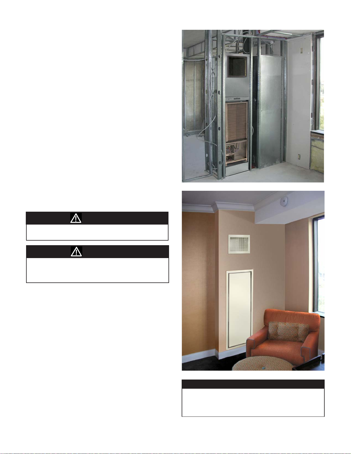
Figure 11: Typical Side by Side Unit Installation
Note: Check the unit data plate for correct voltage
with the plans before installing the equipment.
WARNING
Make sure all electrical ground connections are made in
accordance with local code.
WARNING
The contractor shall cover the units to protect the machines
during nishing of the building. This is critical while spraying
reproong material on bar joists, sandblasting, spray painting
and plastering.
For Optimum Unit Performance and to
Help Minimize Noise and Vibration
● Adhere to the "Critical Dimensions" for locations of
framing and distances to the cabinet.
● Install a 1/4" thick vibration isolation pad under the
entire footprint of the unit cabinet base.
● Be sure there are no kinks and that the stainless
steel braided hoses do not come in contact with and
vibrate on chassis and cause noise.
● Ensure there is no metal-to-metal contact between
return air grille and cabinet and the discharge
diffuser and the cabinet, use provided gaskets.
● Air balancing in ducted applications is critical for
proper airow at each diffuser.
NOTICE
Top air discharge units will require turning vanes and/or a
volume damper for proper air flow and balancing, to minimize turbulence. These components must be field-installed
and furnished in accordance with SMACNA guidelines.
IM 986-2 / Page 11 of 48
Page 12
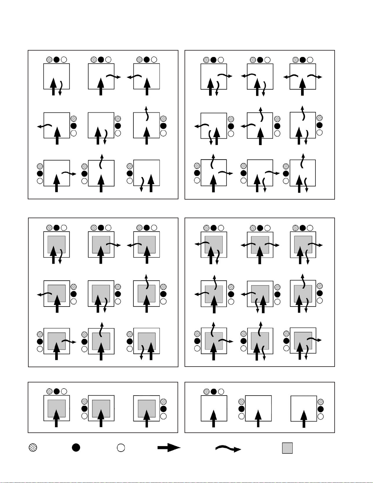
Cabinet Configurations
Figure 12: Single Side Discharge
Figure 13: Double Side Discharge
Figure 14: Side & T op Discharge (See Notice on page 11) Figure 15: Double Side & Top Discharge (See Notice on page 11)
Figure 16: Top Discharge (See Notice on page 11) Figure 17: Closed Plenum – Field Modication Required
= Return Riser = Supply Riser = Drain = Return Air = Discharge Air = Top Discharge
Page 12 of 48 / IM 986-2
Page 13

Figure 18: Typical Framing & Discharge Arrangements
Double Side Discharge
= Return Air
= Discharge Air
Typical Ducted
Application
NOTICE
Top air discharge units will require turning vanes and/or a
volume damper for proper air flow and balancing, to minimize turbulence. These components must be field-installed
and furnished in accordance with SMACNA guidelines.
Note: All ducted applications require a unit that utilizes an ECM-X13 or ECM 2.3 motor (sizes 021-036).
X13 motors are factory set for 2-speeds, 2 and 4 tap. For ducted unit applications only position 1 and 2-speed
motor taps should be used.
Additionally, static pressure must not exceed 0.40 inch static. See table below.
ECM-X13 Motor CFM - Sizes 021 - 036 External Static Pressure (Ducted Applications)
External Static Pressure, WC"
Unit Size Speed
Speed 1
Speed 1
021
024
Speed 2
030
Speed 2
036
Speed 2
Speed 1
Speed 2
Speed 1
0 0.05 0.10 0.15 0.20 0.25 0.30 0.35 0.40
830
770
830
770
1200
1080
1200
1080
820
760
820
760
1180
1060
1180
1060
800
740
800
740
1160
1030
1160
1030
780
720
780
720
1140
1010
1140
1010
770
700
770
700
1120
990
1120
990
760
690
760
690
1100
970
1100
970
730
660
730
660
1080
950
1080
950
850
780
850
780
1230
1100
1230
1100
710
640
710
640
1060
930
1060
930
IM 986-2 / Page 13 of 48
Page 14
Critical Dimensions
Critical Dimensions
Location of studs is critical for proper installation and
t up and can help to reduce unit noise due to vibration
when properly installed.
Figure 19: Framing Locations to Unit Openings
Note: If the unit cabinet was shipped without
risers attached it will be necessary to remove the
appropriate riser knockouts prior to positioning the
cabinet and connecting to the riser stub outs.
Figure 20: Vertical Riser Stub-Outs Locations to Unit
Knockouts
Unit Size 021-036 = 4.54"
Unit Size 009-018 = 3.125"
1/2" Conduit Fitting
for Electrical Supply
Unit Front
Return Air
Table 1: Reference Locations for Framing
Framing Locations
Unit
Size
A
80" 18" 2.07" 6" 22.25" 58.75" 61" 79" 3.125" 3.125"
18" × 18"
92" 18" 2.07" 6" 22.25" 58.75" 73" 91" 3.125" 3.125"
96" 18" 2.07" 6" 22.25" 58.75" 77" 95" 3.125" 3.125"
80" 24" 2.125" 6" 28.25" 59.5" 63" 79" 4.54" 3.125"
24" × 24"
92" 24" 2.125" 6" 28.25" 59.5" 75" 91" 4.54" 3.125"
96" 24" 2.125" 6" 28.25" 59.5" 79" 95" 4.54" 3.125"
1
Dimension includes approximately 1/4" for vibration isolation pad
2
Dimension “E” ± 0.125
3
Dimension “G” will vary based on diffuser size. Refer to Table 2, Discharge Knockout Openings on page 16.
4
Dimension “H” will vary based on cabinet height selected.
88" 18" 2.07" 6" 22.25" 58.75" 69" 87" 3.125" 3.125"
88" 24" 2.125" 6" 28.25" 59.5" 71" 87" 4.54" 3.125"
B
C
1
D
2
E
1
F
Dimensions do not include 1/4" vibration isolation pad
1, 3
G
1, 4
H
J K L M N
58.08"
37.50"
2.38"
3.3" 7.9" 12.4"
3.13" 7.63" 12.13"
Page 14 of 48 / IM 986-2
Page 15
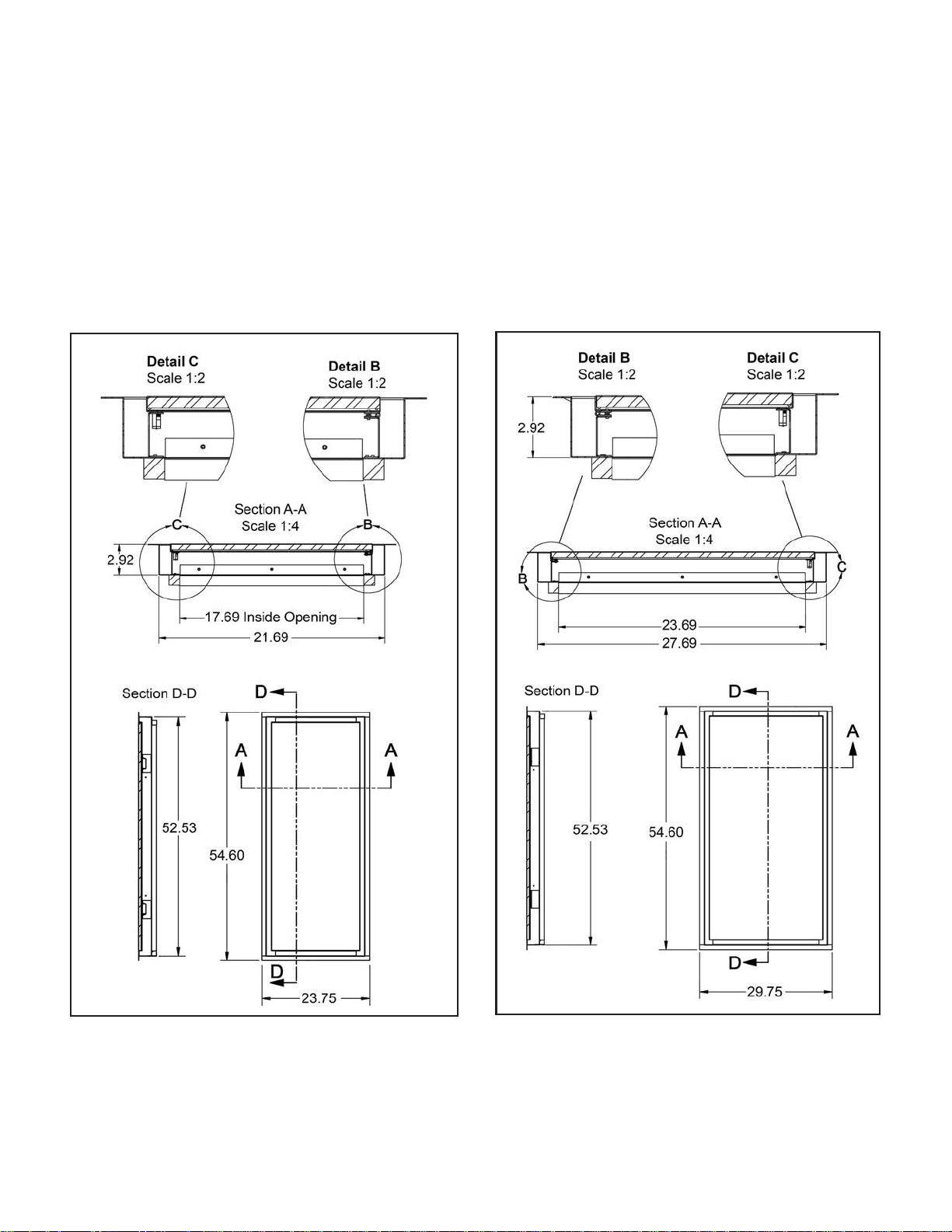
Critical Dimensions
Return Air Grille/Panel Dimensions
Location of studs in relation to the unit and the return
air grille panel are critical for proper installation and
t up. When installed, the return air grille gasket must
compress and seal completely against the outer edge of
the cabinet and around the inner front panel and lter
bracket. See page 24, “Installing The Return Air/Grill
Panel” and page 14, gure 19 “Framing Locations to
Unit Openings”.
Figure 21: Unit Sizes 009 - 018 (18" x 18" Cabinet)
Figure 22: Unit Sizes 021 - 036 (24" x 24" Cabinet)
IM 986-2 / Page 15 of 48
Page 16

Installation Procedure
CAUTION
!
Installation and maintenance is to be performed only by qualied
personnel who are familiar with, and in compliance with state, local
and national codes and regulations, and experienced with this
type of equipment. Sharp edges and coil surfaces are potential
injury hazards. Avoid contact with them.
Note: Refer to "Critical Dimensions", page 14 to
determine the correct recess depth from the front of
the unit to the drywall face. When the installation is
complete, the return air grille/panel frame must meet
to seal with the cabinet discharge opening and the
discharge air diffuser duct must meet and seal with
the discharge opening.
Risers and Cabinet
1. Position the cabinet and risers within the building
pipe chase and align with the unit on the oor above
and/or below (Figure 23).
Figure 23: Position the Cabinet and Risers
Riser Couplings
Connect to Risers
on Unit Above
Inlet, Outlet and
Condensate
Risers
2. Using the riser extensions, make preliminary riser
connections between the units above and or below
to assure proper riser alignment (supply, return and
condensate). See gure 20 on page 14.
3. After all components are aligned properly, anchor
the unit cabinet to the oor using the McQuay
provided mounting brackets (Figure 24).
4. Locate the two (2) mounting brackets in the parts
bag and position them near the back corners of
the unit, or one on a side and one on the back,
whichever location or combination is most suitable,
as illustrated in gure 24. Cut away an area of the
1/4" isolation pad at the mounting bracket locations.
Contractor is responsible for the appropriate
fasteners to secure the brackets to the oor, as local
codes dictate.
Figure 24: Position the Cabinet for Securing to the Floor
with Mounting Brackets (2)
Stud Wall Floor Plate
and Finish Wall
Location
Risers Through
Floor Opening
1/4" Isolation Pad
Riser Extensions
Align and Connect
to Couplings and
Unit Above
IMPORTANT
A eld-supplied ¼” thick isolation pad should be installed now
(Figure 23).
IMPORTANT
The cabinet must be centered between the wall studs and plumb
vertically for the grille/panel frame and diffuser to properly align
and seal to the cabinet. Use of a 4' level is recommended.
1/4" Vibration
Isolation Pad
Unit Cabinet 3
Finished Wall
Unit Front
1
/
8
" from Finished Wall
Back of
Unit
Provided Mounting
Brackets (2)
Fasteners (by others)
Stud Wall Floor Plate
Page 16 of 48 / IM 986-2
Page 17

Note: Be sure that each riser stub-out (supply &
return) are centered within the riser knockout in
the cabinet (Figure 25). If there is a void between
the stub-out and the stub-out seal on the cabinet
interior, this indicates that the stub-out is not properly
centered within the knockout.
Figure 25: Center the Riser Stub-Outs in the Knockouts and
within Seals on the Cabinet Interior
Knockouts
on Cabinet
Exterior
Riser Knockouts
WARNING
Before furring-in units, hydrostatically test the risers and
unit connection joints in accordance with local building
codes, to make sure they are leak-proof.
Note: Perform "Cleaning and Flushing Water
System" Procedure Below.
CAUTION
When furring-in units make sure that no screws or nails
penetrate the unit cabinet.
8. Layout the stud wall oor plates and frame-in
unit referencing “T ypical Framing & Dischar ge
Arrangements” on page 13 and “Critical Dimensions”
on page 14 and table 1.
Note: Before cutting and hanging drywall, remove
the appropriate discharge air opening knockout. See
T able 2). Protect unit from construction debris with a
protective cover.
Cabinet
Interior
Stub-Out Connections with
Valves Centered within
Knockouts and Seals
Stub-Outs
Seals
CAUTION
The unit is not designed to support the weight of the risers.
Anchor them securely to the building structure.
5. Anchor risers to the building structure to prevent
vertical riser movement greater than, plus or minus
one inch to allow for riser expansion or contraction.
Table 2: Discharge Knockout Openings
Unit Size
W H W H W H W H
009–012
015–018
021–024 NR NR 18" 14" 18" 10" 18" 18"
030–036 NR NR
NR = Not Recommended
Single Double Triple Single-Top Opening
14" 16" 14" 8" NR NR 12" 12"
14" 16" 14" 8"
Discharge Openings
14" 8"
18" 14" 18" 10" 18" 18
12" 12"
Cleaning and Flushing Water
System
CAUTION
Prior to first operation of any unit, the water circulating
system must be cleaned and flushed of all construction dirt
and debris or damage will occur.
1. Prior to rst operation of any unit, the water
circulating system must be cleaned and ushed of all
construction dirt and debris.
If the units are equipped with water shutoff valves,
either electric or pressure operated, the supply and
return runouts must be connected together at each
unit location. This will prevent the introduction of
dirt into the unit (Figure 26).
6. Solder all supply and return riser connections to
units above and/or below.
7. Remove riser ties used to secure the risers to the
cabinet during shipping.
IM 986-2 / Page 17 of 48
Page 18

Figure 26: Connections for ushing system piping
Adapter, MPT x Straight Pipe Thread
included with flexible hoses
Note: Use for making connections to the
supply & return valves for the "Cleaning
and Flushing Water System" procedure.
2. Fill the system at the city water makeup connection
with all air vents open. After lling, close all air vents.
The contractor should start main circulator with
the pressure reducing valve open. Check vents in
sequence to bleed off any trapped air, ensuring
circulation through all components of the system.
Power to the heat rejector unit should be off, and the
supplementary heat control set at 80°F (27°C).
While circulating water, the contractor should check
and repair any leaks in the unit and surrounding
piping. Drains at the lowest point(s) in the system
should be opened for initial ush and blow-down,
making sure city water ll valves are set to make up
water at the same rate. Check the pressure gauge at
pump suction and manually adjust the makeup to
hold the same positive steady pressure both before
and after opening the drain valves. Flush should
continue for at least two hours or longer until the
drain water is clean and clear.
Once the system has been lled with clean water and
antifreeze (if used), precautions should be taken to
protect the system from dirty water conditions.
NOTICE
It is not McQuay International’s policy to make recommendations on water treatment. However, the general contractor or owner should contact a local water treatment company regarding water treatment. A fouled closed loop water
system will lead to premature component failure.
Note: Contact a local water treatment company to
conrm water clarity prior to unit operation.
Dirty water will result in system wide degradation
of performance and solids may clog system-wide
valves, strainers, ow regulators, etc. Additionally,
the heat exchanger may become clogged which
reduces compressor service life or causes premature
failure.
6. Set the loop water controller heat add setpoint
to 70°F (21°C) and the heat rejection setpoint to
85°F (29°C). Supply power to all motors and start
the circulating pumps. After full ow has been
established through all components including the
heat rejector (regardless of season) and the vented
air and loop temperatures have been stabilized, each
of the units will be ready for check, test and start-up,
air balancing, and water balancing.
Table 3: Air Limits
Cooling Heating Cooling Heating
Min. Ambient Air 50°F/10°C 50°F/10°C 40°F/5°C 40°F/5°C
Normal Ambient Air 80°F/27°C 70°F/21°C 80°F/27°C 70°F/21°C
Max. Ambient Air 100°F/38°C 85°F/29°C 100°F/38°C 85˚F/29°C
Min. Entering. Air 50°F/10°C 50°F/10°C 50°F/10°C 40°F/5°C
Normal Entering Air, 80°F/67°F 70°F 80°F/67°F 70°F
db/wb 27/19°C 21°C 27/19°C 21°C
Max. Entering Air 100/83°F 80°F 100/83°F 80°C
db/wb 38/28°C 27°C 38/28°C 27°C
Standard Range Geothermal Range
Units Units
3. Shut off supplemental heater and circulator pump
and open all drains and vents to completely drain
down the system. Short circuited supply and return
runouts should now be connected to the unit supply
and return connections. Do not use sealers at the
swivel are connections of hoses.
4. Flush system with water for 2 hours or longer until
water is clean.
5. Rell the system with clean water. Test the water
using litmus paper for acidity, and treat as required
to leave the water slightly alkaline (pH 7.5 to 8.5).
The specied percentage of antifreeze may also be
added at this time. Use commercial grade antifreeze
designed for HVAC systems only. Do not use
automotive grade antifreeze (See Table 5 on page 19
for Antifreeze Correction Factors).
Page 18 of 48 / IM 986-2
Table 4: Water Limits
Standard Range Geothermal Range
Units Units
Cooling Heating Cooling Heating
Min. Entering. Water 55°F/13°C 55°F/13°C 30°F/-1°C 20°F/-6°C
Normal Entering. Water 85°F/29˚C 70˚F/21°C 77°F/25˚C 40˚F/5°C
Max. Entering. Water 110°F/43°C 90°F/32°C 110°F/43°C 90°F/32°C
At ARI flow rate.
Maximum and minimum values may not be combined. If one value
is at maximum or minimum, the other two conditions may not exceed the
normal condition for standard units. Extended range units may combine any
two maximum or minimum conditions, but not more than two, with all other
conditions being normal conditions.
CAUTION
Units must be checked for water leaks upon initial water
system start-up. Water leaks may be a result of mishandling or damage during shipping. Failure by the installing
contractor to check for leaks upon start-up of the water
system could result in property damage.
Page 19

Table 5: Antifreeze Correction Factors
Ethylene Glycol
Cooling Capacity 0.9950 0.9920 0.9870 0.9830 0.9790
Heating Capacity 0.9910 0.9820 0.9770 0.9690 0.9610
Pressure Drop 1.0700 1.1300 1.1800 1.2600 1.2800
10% 20% 30% 40% 50%
Propylene Glycol
Cooling Capacity 0.9900 0.9800 0.9700 0.9600 0.9500
Heating Capacity 0.9870 0.9750 0.9620 0.9420 0.9300
Pressure Drop 1.0700 1.1500 1.2500 1.3700 1.4200
10% 20% 30% 40% 50%
Methanol
10% 20% 30% 40% 50%
Cooling Capacity 0.9980 0.9720 – – –
Heating Capacity 0.9950 0.9700 – – –
Pressure Drop 1.0230 1.0570 – – –
Ethanol
10% 20% 30% 40% 50%
Cooling Capacity 0.9910 0.9510 – – –
Heating Capacity 0.9950 0.9600 – – –
Pressure Drop 1.0350 0.9600 – – –
Power Wiring From Building to Unit
DANGER
!
To avoid electrical shock, personal injury or death:
1. Installer must be qualied, experienced technician.
2. Disconnect power supply before installation to prevent
electrical shock and damage to equipment.
1. Locate the electrical power supply wiring from the
building and feed wiring through the 1/2" conduit
tting (strain relief) on the unit as shown in Figure
27 & 28, following local electrical codes and
regulations.
Figure 27: Supply Electric Wiring from Building to Unit
1/2" Knockout for
Supply Wiring
Figure 28: Wire to Unit Switch
2. If a remote wall-mounted thermostat is being used,
install a 24-volt thermostat wiring cable with at
least 6 wires from the unit low voltage terminal strip
(Figure 29) to the thermostat location.
Flexible Metal Conduit &
Strain Relief
3. If a wireless remote thermostat was ordered to
control the unit, it is recommended that the Remote
Control Node (RCN) be installed now.
IM 986-2 / Page 19 of 48
Page 20

Figure 29: Low V oltage Terminal Strip for Thermostat Wiring
2-Speed
Fan Switch
Thermostat Low
Voltage Terminal Strip
Note: See specic thermostat installation manual
for wiring and operation of thermostat. Install wall
mounted thermostat while completing dry wall
installation.
Connect Condensate Drain Hose to Drain
Stub Out
1. Remove the two (2) screws located along the back
edge of the drain pan, holding it in place
(Figure 30).
Water Connections
All piping connections should be made using good
plumbing practices and in accordance with any and all
local codes that may apply.
Unit Piping Connection
Unit sizes 009 through 018 coil connections are
gooseneck style, made of copper tubing with 1/2" FPT.
Unit sizes 021 through 036 have 3/4" FPT connections
(Figure 31).
Shutoff/Balancing Valve
Each heat pump requires a shutoff valve on both the
supply and return risers for easy serviceability and
removal of the chassis when necessary.
We suggest using a factory installed 2-way motorized
isolation valve on the return line of the chassis and a
Auto Flow Regulator (AFR) installed on the supply line
which allows proper water ow in a given size unit.
Each valve package has 1/2" FPT or 3/4" FPT threaded
connections (Figure 32).
Figure 31: Typical Motorized Valve Piping
2. Adjust the direction of the condensate drain hose
and slip it over the drain stub out. Using the
provided clamp, secure the hose by tightening the
clamp.
3. Reinstall the secondary drain pan with the two (2)
screws removed in step 1.
Figure 30: Connect Drain Hose to Drain Stub Out
Two (2) Screws Holding
Pan in Place
Drain
Stub Out
Hose Clamp
FPT Return
Connection
2-Way
Motorized
Valve
FPT Supply
Auto Flow
Regulator
Connection
Adding A Motorized Valve & Auto Flow
Regulator
The Vertical stack water source heat pump chassis can
be congured with a 2-way motorized valve. The 2-way
motorized valve is mounted on the return line of each
unit and the Auto Flow Regulator (AFR) is mounted to
the supply line. Valve assemblies terminate with either
a 1/2" (unit sizes 009-018) or 3/4" (unit sizes 021-036)
NPT threaded connection and will accommodate factory
supplied hoses.
Page 20 of 48 / IM 986-2
Page 21

Make Flexible Hose Connections to the
Supply and Return Valves From Riser
Stub-Outs
1. Using the specied supply and return hoses make
supply and return hose connections to the riser stubouts (Figure 32).
Note: The MPT straight pipe adapters can be
removed from the swivel end of the exible hoses
now and threaded onto the chassis FPT supply
and return pipe connections (Figure 33). This will
make hose connections to the chassis easier when
the chassis is partially installed.
Note: To complete the exible hose connections
to the chassis, only partially install the chassis
into the cabinet as shown on page 22, gure 35
“Installing Unit Chassis”.
Important When Handling Chassis
Note: If using a hand truck to move chassis, tip
the chassis forward or back only, pivoting on the
ends of the chassis rails. Tipping and pivoting
the chassis side to side on the long edge of the
rails will damage the rails and the rubber vibration
isolators.
!
CAUTION
2. Attach the (MPT) xed hose ends to the female
connections on the valves. Using two crescent
wrenches, one to hold the valve pipe connection and
the second on the hose end, tighten the connections.
Figure 32: Make supply and return hose connections to the
valves from the riser stub-outs
Flexible Hose
2-Position
Hand Valve
Slots in the chassis rails that may be used as hand holds
have sharp metal edges. To avoid personal injury, heavy
protective gloves should be used while moving and lifting
the unit chassis.
Figure 34: Tip Chassis Front to Back Only, Pivoting on the
Ends of the Rails
Do not tilt chassis side to
side on long edge of rails
or damage will occur
Tilt chassis front to back on
end of rails when handling
and moving
Figure 33: Flexible Return and Supply Hoses (Field-installed)
Assembled Length
Fixed End, MPT
Female Swivel
Adapter, MPT x Straight Pipe Thread
Note: Connects to the chassis FPT supply & return
connections.
IM 986-2 / Page 21 of 48
Page 22

Installing Unit Chassis
1. Thread the MPT adapters removed from the swivel
ends of the exible hoses onto the chassis FPT
supply and return pipe connections. Using two
crescent wrenches, one to hold the chassis pipe
connection and the second on the adapter tting,
tighten the connections.
2. Install the chassis by sliding it into the cabinet
opening until the chassis support rails sit on the
cabinet rails. Slide the chassis into the cabinet
until there is approximately a 10" space between
the chassis coil and the cabinet. This will allow
adequate clearance to connect the exible hoses to
the chassis coil. For safety, place a 6" high block
under the chassis rails to support the chassis as
shown in Figure 35.
Figure 35: Slide chassis partially into the unit cabinet
Approximately
10" gap to
make hose
connections
Figure 36: Slide Chassis into Cabinet Leaving a 10" Gap
for Clearance to Make Flexible Hose Connections
Supply
Connection
Return Connection
Making Cabinet to Chassis Wiring
Connections
6" high blocks to
support chassis
2. Thread the female swivel ends of the hoses on to
the water supply and return connections. Using two
crescent wrenches, one to hold the straight MPT
adapter and the second on the exible hose swivel,
tighten the connections. (Figure 36).
1. Locate the wires and plugs in the upper fan section
of the unit that connect to the unit chassis.
2. Plug in the wires from the top cabinet section into
the proper molex connectors on the chassis (Figure 37).
Figure 37: Plug unit component wiring from the top cabinet
section into the proper connectors on the chassis (Unit Size
021-036 Chassis Shown)
Main Power Connector
Note: On unit sizes
009-018 the Main
Power Receptacle and
Thermostat Connector
locations are switched
Fan Control
Connector
Thermostat Wiring
Connector
2. Push the chassis into the cabinet until it makes
contact with the stops on the rails at the rear of the
cabinet.
Page 22 of 48 / IM 986-2
Note: Be sure there are no kinks and that the
stainless steel braided hoses do not come in contact
with and vibrate on chassis and cause noise. Also be
sure not to pinch wires between cabinet and chassis
when inserting chassis.
Page 23

Installing the (Optional) Remote Control
Node (RCN) For Use With The Optional
Wireless Thermostat
DANGER
!
Disconnect all electrical power before servicing unit.
Electrical shock will cause severe injury or death.
Figure 39: Connect Wires to the RCN Terminals and snap
the plastic standoffs onto Board
Plastic Standoffs (4)
Remote Control
Node (RCN)
1. Remove the panel with the low voltage terminal
strip by removing two (2) screws at the front of the
cover and three (3) located on the underside. (Figure
38). The wires connected to the manual fan speed
switch may be removed for easier access.
Note: There are two methods for installing the RCN
to the unit. The RCN mounts on the back of the bezel
(blank control pad) and this assembly snaps into
the knockout on the face of the unit. This method
is not recommended since future replacement is
more difcult. The preferred method for a new unit
installation is illustrated below (Figures 38 – 40).
Figure 38: Remove the Cover Plate with the Low Voltage
Terminal Strip
Terminals
on Back of
Low Voltage
Terminal Strip
RCN Terminals
3. Snap the plastic standoffs into the RCN as illustrated
in Figure 39.
4. Reach inside the area behind the removed terminal
strip cover and up behind the knockout. Align the
standoffs on the board with the provided standoff
holes on the knockout plate and snap the standoffs
into the holes (Figure 40).
Figure 40: Secure the RCN to the Unit with the Standoffs
2. Connect the provided wiring to the RCN terminals
as shown in Figure 39.
Plastic
Standoffs
(4)
RCN
RCN to Low Voltage
Terminal Connectors
5. Connect the RCN wires with connectors to the low
voltage terminals and reinstall the terminal strip
cover.
IM 986-2 / Page 23 of 48
Page 24

Installing The Return Air Grille/Panel
1. Install the return air grille/panel assembly (Figure
41). Center, level and plumb the frame inside the
framed opening. Push the assembly into the opening
until the gaskets compress against the cabinet, and
the frame face is tight to the nished wall.
Note: Shims should be used to make up the space
between the studs and the panel frame at the
locations of the fasteners on the panel frame (4).
Adhere them to the panel frame to keep them in
place (Figure 41).
Figure 41: Installing the Panel Door Frame
Note: Be sure the bottom ange of the door frame
slides beneath the cabinet ange, as shown in Figure
41. This seal must compress between the bottom
panel ange and the bottom cabinet ange when
the installation of the panel door frame is complete.
2. Check that the panel door frame is centered within
the opening and seals completely to the cabinet
return air opening. Also conrm that the room
side ange of the frame is level, plumb and rmly
against the drywall. Secure the hinged panel door
frame with the 4 screws provided.
Seal Gasket on the
Back of the Panel
Door Frame along
top and two sides
Shims to Make Up
Space Between Framed
Opening and Panel
Door Frame
Door Panel Bottom
Flange to Slide
Beneath Cabinet
Flange
Seal Gasket on Underside of
Cabinet Flange. Door Panel
Flange Slides Underneath and
Compresses to Cabinet
Page 24 of 48 / IM 986-2
Page 25

Installing The Discharge Air Diffuser
1. Adhere eld-provided 1/2" foam seal to the face of
the cabinet around the perimeter of the discharge air
opening (Figure 42).
3. Push the diffuser frame in until it compresses
against the foam seal and the room side frame is
ush against the drywall. Be sure the diffuser frame
is level and plumb and secure it with the two (2)
screws provided.
2. Insert the diffuser into the wall opening and align
the frame with the foam seal.
Note: To avoid bending the adjustable discharge
louvers do not press on them
Figure 42: Installing the Discharge Air Diffuser
Foam seal applied to
the cabinet face, around
perimeter of discharge
air opening
Note: When installed correctly the diffuser frame
should seal to the cabinet discharge air opening and
no discharge air will be lost between the unit and the
wall cavity.
Foam seal (field-furnished & installed)
Diffuser flange
compresses into the
foam seal
Double-deflection
Diffuser
IM 986-2 / Page 25 of 48
Page 26

Twin Units Installation
Twin opposite hand units share a common riser system;
i.e., supply, return, and drain riser. This is commonly
called a “master/secondary” arrangement. The master
unit is shipped with the risers attached. These special
risers have stub-outs for both the master unit and the
secondary unit which must be eld connected and the
following procedures must be followed for all twin unit
installations.
1. Secondary units ship without risers and share
common risers with the master unit. Knockout holes
on the cabinet are provided for the 6" stub outs to
make piping connections to the coil supply and
return and the condensate drain.
Figure 43: Twin Unit Arrangement (Side by Side)
2. Master units are offered in two-pipe systems
with either right-hand or left-hand connections.
Secondary units are offered to accommodate
internal connections to any of these riser systems or
locations.
3. The riser location (right or left) is determined by
facing the return air grille panel. The risers are
located on either the right or left of the unit. This
denes the riser location. See Unit Congurations
on page 12.
4. The riser block-off plates are located in the base of
the secondary unit. Block-offs must be installed on
the secondary unit before putting it into position.
Master Unit
Secondary Unit
in Adjoining
Room
6" Stubs on
Master Unit
Risers for
Secondary Unit
Stud Wall
Separating
Rooms
Common
Risers
Page 26 of 48 / IM 986-2
Page 27

MicroTech® III Unit Controller
The MicroTech III Unit Controller includes built-in
features such as random start, compressor time delay,
shutdown, condensate overow protection, defrost
cycle, brownout, and LED/fault outputs. Table 6 shows
the LED and fault output sequences.
The unit has been designed for operation with either
a unit mounted thermostat or a microelectronic wall
thermostat, selected by the manufacturer. Do not operate
the unit with any other type of wall thermostat.
Each unit has a printed circuit board control system. The
low voltage output from the low voltage terminal strip
is AC voltage to the wall thermostat. R is A/C voltage
output to the wall stat.
The 24 volt low voltage terminal strip is set up so R-G
energizes the fan only. R-Y1 energizes the compressor
for cooling operation, R-W1 energizes the compressor
and reversing valve for heating operation. The reversing
valve is energized in the heating mode. The circuit
board has a fan interlock circuit to energize the fan
whenever the compressor is on if the thermostat logic
fails to do so.
The output to the wall stat is AC current. Terminal (R)
on the wall stat can be connected to terminal (R) on the
PC board for AC voltage.
R = AC current
R to G = fan only
R to Y1 = cooling
R to W1 = heat
The MicroTech III unit controller has a lockout circuit
to stop compressor operation if any one of its safety
devices is triggered (high pressure switch and low
temperature sensor). If the low temperature sensor is
triggered, the unit will go into the cooling mode for 60
seconds to defrost any slush in the water-to-refrigerant
heat exchanger. After 60 seconds the compressor is
locked out. If the condensate sensor detects a lled drain
pan, the compressor operation will be suspended only
in the cooling mode. The unit is reset by opening and
closing the disconnect switch on the main power supply
to the unit in the event the unit compressor operation
has been suspended due to low temperature sensor or
high pressure switch. The unit does not have to be reset
on a condensate overow detection.
The MicroTech III unit controller fault output sends a
signal to an LED on a wall thermostat. Table 6 shows
for which functions the fault output is “on” (sending a
signal to the LED).
Table 6: MicroTech III unit controller LED & fault outputs
Mode / Fault
Occupied, Bypass,
Standby, or Tenant Off On Off Energized
Override
Unoccupied On On Off Energized
Condensate Overow On Off Off De-engergized
High Pressure 1 Fault Off Off Flash De-energized
Low Pressure 1 Fault Off Off On De-energized
Low Temperature 1 Fault Flash Off Off De-energized
Brownout
Emergency Shutdown Off Flash Off De-energized
Room/Return Air or Low
Temp Sensor 1 Failure
Service Test Mode
Corrupted
Received
1
1
Enabled
Serial EEPROM
Network “Ofine”
Compressor relay/compressor terminal is labeled COMP, switched line of the
same electric input as any of the L1 terminals.
Yellow Green Red
Flash Flash On De-engergized
Status LED’s Thermostat Alarm Light
Off Flash Off De-energized
On On Off De-energized
On On On De-energized
Off Off Off De-enegized
Output-Terminal “A”
Remote Reset Feature
The Remote Reset feature provides the means to
remotely reset automatic lockouts generated by highpressure and/or low-temperature (in heating) faults.
When the MicroTech III unit controller is in automatic
lockout due to one of these faults, and the cause of
the fault condition has been alleviated, energizing
the O-terminal for 10 seconds or more will force the
MicroTech III unit controller to clear the lockout. A
unit power cycle can also be used to clear an automatic
lockout if the conditions causing the fault have been
alleviated.
The Intelligent reset feature helps to minimize nuisance
trips of automatic reset lockouts caused by highpressure and/or low-temperature (in heating) faults. This
feature clears faults the rst two times they occur within
a 24-hour period and triggers an automatic lockout on
the 3rd fault. The retry count is reset to zero every 24
hours.
The MicroTech III unit controller has built-in night
setback operation. A “grounded’ signal to the “U”
terminal on TB3 of the unit control puts the unit into
the unoccupied mode for night setback operation.
Fan operation terminates and unit control will only
respond to signal at the W2 terminal. Daytime heating
and cooling operation is locked out. +24VAC to W2
energizes the compressor and reversing valve for
heating operation. Night setback operation can be
overridden for two hours by energizing the O on the
TB2 terminal of the unit control for 3 seconds. Day
thermostat setpoints then control the heating and
cooling operation. The MicroTech III unit controller
also accommodates shutdown operation on receipt of a
“grounded” signal to the “E” input, respectively, on TB3
input terminal of the unit control.
IM 986-2 / Page 27 of 48
Page 28

MicroTech® III Unit Controller Terminal Locations and Descriptions
H1 - 1 24 24 VAC Power Input
H1 - 2 C 24 VAC Common
H2 - 1 SL1 Fan Output - Switched L1
H2 - 2 Blank Terminal
H2 - 3 N Fan Neutral
H3 - 1 HP1-1 High Pressure Switch 1 Input Terminal 1
H3 -2 HP1-2 High Pressure Switch 1 Input Terminal 2
H4 - 1 Discharge Air Temp Common
H4 - 2 Discharge Air Temp Signal
H4 - 3 Leaving Water Temp Common
H4 - 4 Leaving Water Temp Signal
H5 - 1 1 I/O Exp Module Common (Gnd)
H5 - 2 I/O Exp Module Common (Gnd)
H5 - 3 I/O Exp Module +5 VDC
H5 - 4 I/O Exp Module SPI CE1
H5 - 5 I/O Exp Module SPI CLK
H5 - 6 I/O Exp Module SPI OUT
H5 - 7 I/O Exp Module SPI IN
H5 - 8 I/O Exp Module +12 VDC
H5 - 9 I/O Exp Module 24 VAC
H5 - 10 I/O Exp Module 24 VAC
H5 - 11 Spare
H5 - 12 Spare
H6 - 1 1 Condensate Overow Signal Input
H6 - 2 Low Temp 1 Sensor Common
H6 - 3 Low Temp 1 Sensor Signal
H6 - 4 Low Pressure Switch 1 Source Voltage
H6 - 5 Low Pressure Switch 1 Signal
H6 - 6 Reversing Valve 1 Common
H6 - 7 Reversing Valve 1 Output
H7 - 1 1 Dummy Terminal
H7 - 2 Dummy Terminal
H7 - 3 Red LED Output
H7 - 4 Green LED Output
H7 - 5 Yellow LED Output
H7 - 6 Red-Green-Yellow LED Common
H8 - 1 1 Isolation Valve/Pump Request Relay N/O
H8 - 2 Isolation Valve/Pump Request Relay N/C
H8 - 3 24 VAC Common
H9 - 1 1 Return Air Temperature Signal
H9 - 2 Return Air Temperature Common
TB1 - 1 1 Room Sensor LED Output
TB1 - 2 2 Fan Mode / Heat-Cool-Auto Input
TB1 - 3 3 Setpoint Adjust Input
TB1 - 4 4 Room Temperature Sensor / Tenant Override
TB1 - 5 5 DC Signal Common
Test-1 R 24 VAC
Test-2 W2 Heat Stage 2 Input
Test-3 W1 Heat Stage 1 Input
Test-4 Y2 Cool Stage 2 Input
Test-5 Y1 Cool Stage 1 Input
Test-6 G Fan
TB2 - 1 R 24 VAC
TB2 - 2 A Alarm Output
TB2 - 3 W2 Heat Stage 2 Input
TB2 - 4 W1 Heat Stage 1 Input
TB2 - 5 Y2 Cool Stage 2 Input
TB2 - 6 Y1 Cool Stage 1 Input
TB2 - 7 G Fan Input
TB2 - 8 O Tenant Override Input
TB2 - 9 C 24 VAC Common
TB3 - 1 E Mark IV Emergency Shutdown Input
TB3 - 2 U Mark IV Unoccupied/Occupied Input
L1 - 1 L1 - 1 Line Voltage Terminal 1
L1 - 2 L1 - 2 Line Voltage Terminal 2
L1 - 3 L1 - 3 Line Voltage Terminal 3
N1 N1 Neutral Terminal 1
N2 N2 Neutral Terminal 2
N3 N3 Neutral Terminal 3
Table 7: Conguration Jumper Settings
Jumper Description Options
JP1 Mode
Shorted for service/test operation mode
JP2 Fan operation only applies to Open for continuous fan operation
network controls Shorted for cycling fan operation
JP3 Freeze protection
Shorted for antifreeze protection
JP4 Future spare Future spare
JP5 Set point adjustment range only Open for adjustment range of -3.0° to +3.0° F
applies to network controls with a Shorted for 50° to 90° F adjustment range
room temperature sensor
JP6 Room control type
Shorted for room temperature sensor control, MicroTech III only
JP7 Future spare Future spare
JP8 Future spare Future spare
Page 28 of 48 / IM 986-2
Open for normal operation mode
Open for water freeze protection
Open for thermostatic room control
Page 29

Note: A random start delay time between 180 and
240 seconds is generated at power up.
Figure 44: MicroT ech III Unit Controller Terminal Locations
Location of Conguration Jumpers on the MicroTech III
Unit Controller
IM 986-2 / Page 29 of 48
Page 30

I/O Expansion Module
Table 8: I/O Expansion Module LED & Fault Outputs
Mode / Fault
Terminal “A”
Yellow Green Red
Status LED's
Thermostat Alarm
Light Output
For installation and operation information on MicroTech
III unit controller and other ancillary components, see:
• IM 927 - MicroTech III Unit Controller for Water
Source Heat Pumps (LonWorks).
The I/O Expansion Module is a eld-installed or factory
installed option. It is an extension of the MicroTech III
unit controller and provides extra functionality.
The I/O Expansion Module has 2 main purposes:
• The I/O Expansion Module has outputs to control
electric heat on a standard Water Source Heat Pump.
• The I/O Expansion Module has an independent LED
annunciator to identify operational fault conditions
on second stage equipment.
Figure 45: I/O Expansion Module Conguration Jumper
Terminals
Jumper Terminals
Features
Second Circuit
• High pressure switch
• Low pressure switch
• Low suction line temperature sensor
• Compressor output
• Reversing valve
Standard Heat Pumps / Single Circuit Units
• Monitors entering water temperature for
boilerless electric heat control
• Outputs for medium and high speed fan controls.
Invalid Conguration
Jumper Setting
Base Board
Communication Fail
High Pressure #2 Fault Off Off Flash De-energized
Low Pressure #2 Fault Off Off On De-energized
Low Suction Temp #2 Fault Flash Off Off De-energized
Sensor Failures Low Suction
Low Suction Temp #2, Flash Flash On De-energized
1
EWT (w/ Boilerless EH only)
2
Service Test Mode Enabled Flash Flash Flash De-energized
Unoccupied Mode On On Off Energized
Occupied, Bypass,
Standby, or Tenant
Override Modes
Normal Operation Off On Off De-energized
Flash Flash Off De-energized
Off Flash Flash N/A
Off On Off Energized
Note: Mode / Faults are listed in order of priority.
1
Boilerless electric heat only
2
Alarm/fault LED indications take precedence over service test mode LED
indication. The controller shall use service test mode if the service test mode
jumper is installed, even if the LED’s indicate an alarm/fault.
Table 9: I/O Expansion Module Jumper Designations
Jumper Description Options
JP1 Number of
JP2
Water Reheat Shorted to enable reheat
JP3 and JP4 open for no
supplemental heat
JP3 Supplemental JP3 open, JP4 shorted for
& JP4 Heat Type boilerless electric heat
JP3 and JP4 shorted is an
invalid setting
JP5 and JP6 open for single-speed fan
JP5
& JP6 Selection JP5 shorted and JP6 open for
two-speed fan
JP 5 and JP6 shorted is an
invalid setting
JP7
Speed Type Shorted for two-speed compressor
JP8 Future Spare
Compressors Shorted for dual compressor
Hot Gas/
Fan Speed three-speed fan
JP5 open, JP6 shorted for
Compressor Open for single-speed compressor
Open for single compressor
Open to disable reheat
Adding an I/O Expansion Module (with an interconnect
cable) to the main controller allows two-stage operation
of the Water Source Heat Pump.
Page 30 of 48 / IM 986-2
Page 31

MicroTech III Controller With
LonWorks® Communication Module
For installation and operation information on
onWorks Communication Module and other ancillary
L
control components, see:
• IM 927 - MicroTech III Unit Controller for Water
Source Heat Pumps (LonWorks).
• IM 933 - LonMaker Integration Plug-in Tool: For
use with the MicroTech III Unit Controller.
• IM 955 - MicroTech III Wall Sensor For use with
MicroTech III Unit Controller with LonWorks
Figure 46: LonWorks Communication Module
The LonWorks communication module will plug into
the MicroTech III unit controller at the CN_LON1
Header (see gure 48, page 34).
Each McQuay water source heat pump can be equipped
with a L
controller is microprocessor-based and is designed
to communicate over a L
network. The unit controller is factory programmed
and tested with all the logic required to monitor and
control the unit. The wall thermostat sets the unit mode
of operation. The unit controller monitors water and air
temperatures, and can communicate fault conditions to a
L
The MicroTech III unit controller include unit-mounted
return air, discharge air and leaving water temperature
sensors. Options include setpoint adjustment and tenant
override and the capability of substituting the return air
sensor with a wall-mounted temperature sensor.
Each unit controller orchestrates the following unit
operations:
Enable heating and cooling to maintain setpoint
Enable fan and compressor operation.
Monitor all equipment protection controls.
onWorks communication module. The
onWorks communications
onWork communications network.
based on a room sensor.
Monitor leaving water temperature.
Relay status of all vital unit functions.
Support optional control outputs.
A set of three status LED's aid in diagnostics by
indicating the water source heat pump operating mode
and alarm conditions. If there are no current alarm
conditions, the Green LED will indicate the normal unit
operating mode as shown in the table below. If there are
one or more alarm conditions present, various LED's
will ash to indicate an alarm condition.
MicroTech III heat pumps with a MicroTech III unit
controller are LonMark certied and designed to be
linked with a centralized building automation system
through a L
onWorks communications network for
centralized scheduling and management of multiple
heat pumps. Wall-mounted room sensors are available
to control the heating and cooling operation of each
MicroTech III Water Source Heat Pump Unit Controller.
Available room sensors include: room sensor with
LED status and tenant override button, room sensor
with LED status, timed-override button, room sensor
with LED status, timed-override button, and setpoint
adjustment, and room sensor with LED status, timedoverride button, setpoint adjustment.
The MicroTech III water source heat pump unit
controller provides control of McQuay water source
heat pumps. The controller enables the mode of
operation, monitors the water and air temperatures, and
indicates fault conditions. Each unit controller is factory
programmed, wired, and tested for effective operation
of your McQuay water source heat pump.
The MicroTech III water source heat pump controller
onWorks technology. One of the following two
uses L
versions of the application software is loaded into the
controller at the factory.
LonMark® 3.4 certied application code is the current
standard application code for MicroTech III units.
Use LonMark application code in new applications
including:
Units that operate stand alone.
Monitor discharge air temperature.
IM 986-2 / Page 31 of 48
Page 32

MicroTech III Controller With BACnet
Communication Module for Native
BACnet Communications
McQuay water source heat pumps are available with
a factory mounted and tested McQuay BACnet communication module The module is factory programmed
and tested with all the logic required to control the unit,
and is designed to communicate over a BACnet MS/TP
communications network to a building automation system (BAS). The module operates the compressor, fan,
and reversing valve as required to maintain the space
temperature within the current setpoints. Data regarding
equipment status, water and air temperatures, and fault
conditions can be monitored by any BAS. Setpoints and
other system preferences may be changed remotely using a front end workstation or service tool software.
Each BACnet-compliant controller has the following
operating features:
Start-up – The unit will not operate until all the
inputs and safety controls are checked for normal
conditions.
Fan operation – Fan operation can be customized in
software to run continuously during occupied mode,
or to cycle ON or OFF appropriately on a call for
heating and cooling.
Cooling mode – On a call for cooling, the compres-
sor and fan start immediately. Compressor runtime is calculated as a percent of full cycle time
(17 minutes) using proportional-integral control to
maximize efciency.
The module makes operational data and commands
available on a communications network using BACnet
objects and properties. Each heat pump controller connects to the communication network using a BACnet
MS/TP communication network, which is a simple
twisted-pair communications connection that operates at
up to 76.8 Kbps. DIP switches on the controller enable
the MS/TP MAC address to be set in the range 0-127. A
status LED on the unit indicates communication activity
on the MS/TP communication network.
Figure 47: MicroTech III BACnet W ater Source Heat Pump
Snap-in Communication Module
Each BACnet-compliant unit includes discharge air
and leaving water temperature sensors, as well as all
equipment protection sensors, signals, and switches.
Wall-mounted room sensors are available to control
heating and cooling operation. Sensors are available
for status override; wall-mounted sensors with tenant
setpoint adjustment lever and timed-override button;
wall-mounted sensors with LED status, timed-override
button, tenant setpoint adjustment buttons, password-
protected eld service access to operational data, and
optional humidity sensor; and wall-mounted sensors
with LCD and programmable operation.
Heating mode – On a call for heating, the com-
pressor and fan start immediately, and compressor
run-time is calculated as a percent of full cycle time
(17 minutes) using proportional-integral control to
maximize efciency.
Short Cycle Protection and Random Start – A start
delay of 180 seconds plus the compressor’s MAC
address in seconds prevents short-cycling and
simultaneous start-up. A minimum 2-minute on time
and 5-minute off time for the compressor further
ensures short-cycle protection.
Occupied Mode – A simple software control signal
from the building automation system or a wallmounted unit puts the unit into occupied mode.
The unit controls compressor and fan operation to
maintain occupied setpoints. High and low limits
for occupied setpoints are software congurable.
Unoccupied Mode – A simple software control
signal from the building automation system or a
wall-mounted unit puts the unit into unoccupied
mode for night setback operation. The unit controls
compressor and fan operation to maintain unoccupied heating and cooling setpoints, which are also
software congurable.
Page 32 of 48 / IM 986-2
Page 33

After-hours Override Mode – A simple software
control signal from the building automation system
or a wall-mounted unit can initiate after-hours heating or cooling in half-hour increments. Maximum
override time is software congurable up to 9.5
hours. This feature can also be disabled in software.
Reversing valve delay – On a call for cooling,
the compressor and fan will start 0 to 30 seconds
later. If the reversing valve output is energized, the
reversing valve output will de-energize 5 seconds
after the compressor energizes. When the load is
satised, the compressor and fan shut off. On a
call for heating, the compressor and fan start. If the
reversing valve output is de-energized, the reversing valve output will be energized 5 seconds after
the compressor starts. When the load is satised, the
compressor and fan shut off. The reversing valve
remains energized.
Load Shed – Load shedding can be orchestrated by
the building automation system using the occupied/
unoccupied command in software.
Brownout Protection – An on-board sensor mea-
sures input voltage and suspends compressor and
fan operation if the supply voltage drops below 82%
of the normal line voltage for a minimum of 10 seconds, creating an alarm available in software. The
alarm automatically resets when the supply voltage
returns to above 90% of normal.
Condensate Overow Protection – A liquid sensor
at the top of the drain pan senses a high water level.
Upon sensing water, cooling operation is suspended,
while heating operation is allowed. The controller
creates an alarm available in software. The alarm
automatically resets when the water level returns to
normal.
Attained T emperature and Water Temperature
Alarms –Attained temperature, water temperature
alarms with software-adjustable setpoints are available in software. The controller samples supply air
and records attained temperatures for heating and
cooling. If after two hours of operation, the attained
temperature does not meet the software-congurable setpoint for heating or cooling as appropriate,
a software alarm occurs. The alarm automatically
resets when the attained temperature is within setpoints. The controller also monitors leaving water
temperature. If the leaving water temperature is
outside software-congurable setpoints, compressor operation is suspended and high or low water
temperature alarms occur. The alarm automatically
resets when the water temperature returns to within
6 deg. F of the setpoint.
Unit Self-test Mode – While the unit is in occu-
pied mode, a self-test can be initiated via software.
Upon initiation of the test, compressor operation is
suspended for a minimum of ve minutes, cooling
attained temperatures are cleared, and attained temperature alarms are cleared. The unit then switches
to full heat for four minutes and then records the
attained supply air temperature. Compressor opera-
tion is then suspended for ve minutes. The unit
then switches to full cooling for four minutes and
the attained supply air temperature is recorded.
Attained temperature alarms are set if the attained
temperatures failed to reach alarm setpoints during
heating or cooling.
Safety Control – The unit monitors refrigerant pres-
sure and generates separate high-pressure and lowpressure alarms available in software. While either
alarm is active, compressor operation is suspended.
In a refrigerant low-temperature condition, an alarm
occurs and the unit operates in cooling mode for 60
seconds to defrost the heat exchanger, after which
compressor operation is suspended. These alarms
can be reset in software or by cycling power to the
controller.
IM 986-2 / Page 33 of 48
Page 34

Figure 48: LonWorks Communication Module Placement on MicroTech III Unit Controller
Page 34 of 48 / IM 986-2
Page 35

Typical Wiring Diagram
Figure 49: MicroTech III Unit Controller, 2-Speed Fan (Toggle or Thermostat), PSC Motor 208-230/60Hz/1-Phase,
Unit Sizes 009-018
Drawing No. 669349301
Legend
Description
Item
C1
C2
CM
COS Condensate Overow Sensor
DSC
FMP
FMR Fan Motor Connect Receptacle
FCP
FCR
FSR Fan Speed Relay
FSS
FS1 Fuse 1
FS2 Fuse 2
HP
ISO
LED1
LP
MIII MicroTech III Main Board
MPP
MPR
OVL Compressor Overload Protector
PDPG Primary Drain Pan Ground
RV
SOS
SLTS
TS1 Fan Speed Terminal Strip
TS2 Thermostat Terminal Strip
TSP
TSR Terminal Strip Connector Terminal
X1
Capacitor-Compressor
Capacitor-Fan
Compressor - Motor
Disconnect Switch
Fan Motor Connector Plug
Fan Connector Plug
Fan Connector Receptacle
Fan Speed Switch - Optional
High Pressure Switch
Isolation Valve - Optional
LED Annunciator / Harness
Low Pressure Switch
Main Power Connector Plug
Main Power Connector Receptacle
Reversing Valve Solenoid
Secondary Overow Sensor
Suction Line Temp Sensor
Terminal Strip Connector Plug
Transformer
Table B
208V
230V ORG
RED
Note:
T
ransformer:
Unused wire to be capped.
IM 986-2 / Page 35 of 48
Page 36

Typical Wiring Diagram
Figure 50: MicroTech III Unit Controller, 2-Speed Fan (Toggle or Thermostat), PSC Motor 265-277/60Hz/1-Phase,
Unit Sizes 009-036
Drawing No. 669349401
Legend
Description
Item
C1
C2
CC
CM
DSC
FMP
FMR Fan Motor Connect Receptacle
FCP
FCR
FPR Fan Power Relay
FSR Fan Speed Relay
FSS
FS1 Fuse 1
FS2 Fuse 2
HP
ISO
LED1
LP
MIII MicroTech III Main Board
MPP
MPR
COS Condensate Overow Sensor
PDPG Primary Drain Pan Ground
RV
SOS
SLTS
TS1 Fan Speed Terminal Strip
TS2 Thermostat Terminal Strip
TSP
TSR Terminal Strip Connector Terminal
X1
Capacitor-Compressor
Capacitor-Fan
Compressor Contactor
Compressor - Motor
Disconnect Switch
Fan Motor Connector Plug
Fan Connector Plug
Fan Connector Receptacle
Fan Speed Switch - Optional
High Pressure Switch
Isolation Valve - Optional
LED Annunciator / Harness
Low Pressure Switch
Main Power Connector Plug
Main Power Connector Receptacle
Reversing Valve Solenoid
Secondary Overow Sensor
Suction Line Temp Sensor
Terminal Strip Connector Plug
Transformer
Page 36 of 48 / IM 986-2
Page 37

Typical Wiring Diagram
Figure 51: MicroTech III Unit Controller, 2-Speed Fan (Toggle or Thermostat), X13 Motor 208-230/60Hz/1-Phase,
Unit Sizes 021-036
Drawing No. 669349701
Legend
Description
Item
C1
C2
CC
CM
COS Condensate Overow Sensor
DSC
FMP
FMR Fan Motor Connect Receptacle
FCP
FCR
FPR Fan Power Relay
FSR Fan Speed Relay
FSS
FS1 Fuse 1
FS2 Fuse 2
HP
ISO
LED1
LP
MIII MicroTech III Main Board
MPP
MPR
PDPG Primary Drain Pan Ground
RV
SOS
SLTS
TB3 Terminal Block
TS1 Fan Speed Terminal Strip
TS2 Thermostat Terminal Strip
TSP
TSR Terminal Strip Connector Terminal
X1
Capacitor-Compressor
Capacitor-Fan
Compressor Contactor
Compressor - Motor
Disconnect Switch
Fan Motor Connector Plug
Fan Connector Plug
Fan Connector Receptacle
Fan Speed Switch - Optional
High Pressure Switch
Isolation Valve - Optional
LED Annunciator / Harness
Low Pressure Switch
Main Power Connector Plug
Main Power Connector Receptacle
Reversing Valve Solenoid
Secondary Overow Sensor
Suction Line Temp Sensor
Terminal Strip Connector Plug
Transformer
Table B
208V
230V ORG
RED
Note:
T
ransformer:
Unused wire to be capped.
IM 986-2 / Page 37 of 48
Page 38

Typical Wiring Diagram
Figure 52: MicroTech III Unit Controller, 2-Speed Fan (Toggle or Thermostat), X13 Motor 265-277/60Hz/1-Phase,
Unit Sizes 021-036
Drawing No. 669349801
Legend
Description
Item
C1
C2
CC
CM
COS Condensate Overow Sensor
DSC
FMP
FMR Fan Motor Connect Receptacle
FCP
FCR
FPR Fan Power Relay
FSR Fan Speed Relay
FSS
FS1 Fuse 1
FS2 Fuse 2
HP
ISO
LED1
LP
MIII MicroTech III Main Board
MPP
MPR
PDPG Primary Drain Pan Ground
RV
SOS
SLTS
TB3 Terminal Block
TS1 Fan Speed Terminal Strip
TS2 Thermostat Terminal Strip
TSP
TSR Terminal Strip Connector Terminal
X1
Capacitor-Compressor
Capacitor-Fan
Compressor Contactor
Compressor - Motor
Disconnect Switch
Fan Motor Connector Plug
Fan Connector Plug
Fan Connector Receptacle
Fan Speed Switch - Optional
High Pressure Switch
Isolation Valve - Optional
LED Annunciator / Harness
Low Pressure Switch
Main Power Connector Plug
Main Power Connector Receptacle
Reversing Valve Solenoid
Secondary Overow Sensor
Suction Line Temp Sensor
Terminal Strip Connector Plug
Transformer
Page 38 of 48 / IM 986-2
Page 39

Start-up
CAUTION
Units must be checked for water leaks upon initial water
system start-up. Water leaks may be a result of mishandling or damage during shipping. Failure by the installing
contractor to check for leaks upon start-up of the water
system could result in property damage.
Cooling or Heating – Manual Operation
Adjust the thermostat heating or cooling setpoint to
maintain desired space temperature.
The MicroTech III unit controller has built-in features
such as random start, compressor time delay, night
setback, load shed, shutdown, condensate overow
protection, defrost cycle, brownout, and LED/fault
outputs. Table 10 shows the LED and fault output
sequences. The 24 volt low voltage terminal strip is set
so R-G energizes the fan. R-W1 energizes the fan and
compressor and reversing valve for heating operation.
R-Y1 energizes the fan and compressor for cooling
mode of operation.
T able 10: LED Fault Indicators
Normal Mode Off On Off Off
High Pressure Fault Off Off Flash On
Low Temperature Fault* Flash Off Off On
Condensate Overflow On Dim Off On
Brownout Off Flash Off On
Load Shed Off Off On Off
Unoccupied Mode On On Off Off
Unit Shutdown Off Flash Off On
LEDs
Indication
Yellow Green Red
Fault
Output
IMPORTANT
Each water source heat pump unit has a compressor and
blower motor. Each component part has and internal
temperature and amperage sensitive overload. If the overload opens it will suspend unit operation. Check component
parts by measuring the winding resistance and looking for
an open circuit.
Additional Accessories – General
Thermostats and Wall Sensors
Easy-to-operate comfort command centers provide a
complete range of deluxe features.
The reversing valve is set up to be energized in the
heating mode. The circuit board has a fan interlock
circuit to energize the fan whenever the compressor is
on.
The MicroTech III unit controller has a lockout circuit
to stop compressor operation if any one of its safeties
opens (high pressure or suction line sensor). If the
suction line low temperature sensor opens, the unit will
go into the cooling mode for 60 seconds to defrost any
slush in the water-to-refrigerant heat exchanger.
After 60 seconds, the compressor is locked out. If
the condensate sensor detects a lled drain pan, the
compressor operation will be suspended only in the
cooling mode. The unit is reset by opening and closing
the disconnect switch on the main power supply to the
unit in the event the unit compressor operation has been
suspended due to low suction line sensor reaching its
set point, or a high pressure switch.
The MicroTech III unit controller has a fault output
signal to an LED on a wall thermostat. Table 10 shows
in which function the fault output is “on” (sending a
signal to the LED).
Wall-Mounted Programmable Electronic
Thermostat (P/N 668810301)
1 Heat/1 Cool, Auto Changeover, Hardwired
• 7-Day, 5-2-Day 5-1-1 Day Programmable
• Congurable
• Single-Stage Heat/Cool Systems
• Single-Stage Heat Pump Systems
• Large Display With Backlight
• Selectable Fahrenheit or Celsius
• Compatible with Gas, Oil, or Electric
• SimpleSet™ Field Programming
• Status Indicator Light
• Relay Outputs (minimum voltage drop in thermostat)
• Remote Sensor Compatible
• Ideally Suited for:
– Residential (New Construction/Replacement)
– Light Commercial
IM 986-2 / Page 39 of 48
Page 40

Specifications–668810301
Electrical rating: • 24 VAC (18-30 VAC)
• 1 amp maximum per terminal
• 3 amp maximum total load
Temperature control range: 45°F to 90°F (7°C to
32°C) Accuracy: ± 1°F (± 0.5°C)
System congurations: 1-stage heat, 1-stage cool, heat
pump, gas, oil, electric
• Relay Outputs (minimum voltage drop in thermostat)
• Remote Sensor Compatible
• Ideally Suited for:
– Residential (New Construction/Replacement)
– Light Commercial
Specifications–668811201
Electrical rating: • 24 VAC (18-30 VAC)
• 1 amp maximum per terminal
• 3 amp maximum total load
Timing:
Anti-short Cycle: 4 minutes
Backlight Operation
Terminations: S1, S2, Y, W/O/B, G2, G1, RC, RH, C
For detailed installation, operation and application refer
to Operation & Application Guide LIA303
Figure 53: Thermostat Parts Diagram - Part No. 668810301
Up button
Down button
Right (fan) button
Left (system) button
Field programming pins
Conguration switch
Reset switch
RC/RH Jumper
Non-Programmable Electronic Thermostat
(P/N 668811201)
1 Heat/1 Cool, Auto Changeover, Fan Speed
Control, Hardwired
Temperature control range: 45°F to 90°F (7°C to
32°C) Accuracy: ± 1°F (± 0.5°C)
System congurations: 1-stage heat, 1-stage cool, heat
pump, gas, oil, electric
Timing:
Anti-short Cycle: 4 minutes
Backlight Operation
Terminations: S1, S2, Y, W/O/B, G2, G1, RC, RH, C
For detailed installation, operation and application refer
to Operation & Application Guide LIAF014
Figure 54: Thermostat Parts Diagram - Part No. 668811201
Up button
Down button
Right (fan) button
Left (system) button
Reset switch
Conguration switch
Reset switch
Fan switch
Field programming pins
RC/RH Jumper
• Congurable
• Single-Stage Heat/Cool Systems
• Single-Stage Heat Pump Systems
• Fan Speed Control
• Large Display With Backlight
• Selectable Fahrenheit or Celsius
• Compatible with Gas, Oil, or Electric
• SimpleSet™ Field Programming
• Status Indicator Light
Page 40 of 48 / IM 986-2
Page 41

Wireless Temperature Control
(T9000)
The T9000 Wireless Temperature Control is designed
to provide precision temperature control without the
installation labor and expense of wiring.
• Powered by AA batteries
• Mounts in any suitable location that will provide
good temperature control.
• Large LCD display provides the user with
current room temperature, set point temperature,
time, program interval, and other system status
information.
For detailed installation, operation refer to Operation &
Maintenance Bulletin OM 984.
The second part of the T9000 system is called a Remote
Control Node or “RCN”. An RCN interfaces with
specic desired HVAC equipment, and communicates
with its thermostat using unlicensed 900 MHz, radio
frequency energy. At the time of installation, the T9000
thermostat is linked to one or more RCN controls. The
thermostat and RCN that have been linked will not
interfere with, or be affected by, any other thermostat
or RCN in adjacent rooms, apartments, or neighboring
homes.
Remote Control Node (RCN)
Used with the Wireless Temperature Control, the
RCN interfaces with specic HVAC equipment, and
communicates with its thermostat using unlicensed
900 MHz, radio frequency energy. Contact your local
McQuay Representative for details.
Programmable Non-programmable
Figure 55: T9000 Overview
IM 986-2 / Page 41 of 48
Page 42

MicroT ech III Wall-Mounted Room T emperature
Sensors
(Kit P/N 669529101, 669529201, 669529001)
Figure 56: MicroT ech III Wall-Mounted Room Temperature
Sensors (669088201 Not Shown)
Sensor 669529101
Sensor 669529201 Not Shown
Sensor 669529001
General
CAUTION
When the optional wall-mounted room temperature sensor is connected to the unit controller, the Return Air
Temperature (RAT) sensor must not be installed. The wallmounted room temperature sensor and return air sensor
must not be connected simultaneously or the unit will not
operate properly.
Specifications
Thermistor resistance (10kΩ)
(Conforms to advance thermal products curve 2)
Ambient T emperature Limits:
Shipping and Storage: 40°F to 160°F (–40°C to 71°C)
Operating: 40°F to 140°F (4°C to 60°C)
Humidity: 5 to 95% RH, non-condensing
Locations: NEMA Type 1, Indoor only
Connections: Color Coded Leads
Wiring Sensors to the MicroTech III Unit
Controller
Figure 58: T emperature Sensor W iring to MicroT ech III Unit
Controller (669529101, 669529201)
Temperature
Sensor Terminals
MicroT ech III Wall-Mounted Room Temperature
Sensors provide electronic sensing of room
temperatures at wall locations. All sensor models feature
a thermistor (10kΩ) and a green LED for unit status.
Tenant ove r r i d e , s e t p o i n t adjustment potentiometer,
thermometer, and a communications port are optional
features available in any combination
This manual provides general information for the
MicroT ech III Wall-Mounted Room Temperature
Sensors. For installation instructions refer to IM 955
Figure 57: MicroTech III Wall Sensor Details
0 to 10 K ohm
Potentiometer
4.59"
Status LED
(Green)
Fan Control
Slide Switch
MicroTech III Unit
Controller TB1 Terminals
Figure 59: T emperature Sensor W iring to MicroT ech III Unit
Controller (669529001)
Temperature
Sensor Terminals
Mode Control
Slide Switch
Page 42 of 48 / IM 986-2
Tenant Override
Momentary Push Button Switch
MicroTech III Unit
Controller TB1 Terminals
Page 43

Optional Remote Sensor
(P/N 66720401)
The fast, easy solution for temperature sensing problems.
• For tamper prone areas
• Poor airow areas
Motorized Isolation Valve & Relay
The motorized valve kit may be ordered as a eld-
installed accessory.
Wired as shown in Figure 60, the motorized valve will
open on a call for compressor operation. Valves for unit
sizes 009 to 018 are 1/2".
• Troubled applications
• Foam gasket prevents drafts through
wall opening
• Mounts to standard 2" x 4" outlet
box
• 2¾"W x 4½"H
1. Remove cover from remote sensor housing.
2. Select an appropriate location for mounting the
remote sensor.
3. Mount remote sensor unit using hardware provided.
4. Install two strand shielded wire between remote
sensor and thermostat. Shielded wire must be used.
Do not run remote sensor wire in conduit with other wires.
• Wire 1 should run between the S1 terminal on the
thermostat and the S1 terminal on the remote sensor
• Wire 2 should run between the S2 terminal on the
thermostat and the S2 terminal on the remote sensor
• Connect the shielding of the wire to the S2 terminal
on the thermostat
5. Disable the main sensor (R12) on the thermostat by
cutting it from the circuit board.
Using a Normally Closed (N/C), power open valve,
wire as illustrated in gure 61.
Figure 60: Normally Closed, Power Open Motorized Valve
& Relay Wiring
Actuator &
Valve Assembly
Figure 61: Normally Closed, Power Open Motorized Valve
& Relay Wiring Detail
Anti-short Bushing
Connector
Conduit
Anti-short
Bushing
Connector
Pin(s), female
connect to terminal H8
Note: Connectors on valve must be cut off and
stripped back and the wires twisted to make
connections to the IV/PR Terminals
Pump Restart Relay Kit P/N 061419001
The MicroTech III unit controller has an internal Pump
Restart Relay connected to H8, Pin 2 for the Normally
Open (N/O) terminal of the internal relay.
Connect to H8, Pin 1 for the Normally Closed (N/C)
terminal of the internal relay.
The output of the internal pump restart relay is 24volts AC and the output is not available when the H8
connection is used to control a motorized valve.
IM 986-2 / Page 43 of 48
Page 44

Troubleshooting
The in and outs of R-410A
R-410A is a non-ozone depleting blend of two
refrigerants - HFC-125 and HFC-32 in a fty percent
mixture. R-410A exhibits higher operating pressure and
refrigeration capacity than R-22. R-410A is intended
for use in new air conditioning applications that have
traditionally been used HCFC-22 (R-22). Due to higher
capacity and pressure of R-410A, it must not be used in
existing R-22 systems.
Although R-410A is non-ammable at ambient
temperature and atmospheric pressure, it can become
combustible under pressure when mixed with air.
Note: Because a water source heat pump operates
under a wide range of water and air temperatures, the
values printed below are to be taken as suggested
pressure and temperatures. All McQuay water
source heat pumps are designed for commercial
use. The units are designed for the cooling
mode of operation and fail safe to cooling. The
reversing valve is energized for the heating mode of
operation.
Superheat Head Pressure Water Delta T
8 to 14 degrees 335-355 PSIG 10° to 14°
All information above is based on ISO standard
13256-1 and tested at these conditions.
Note: R-410A should not be mixed with air under
pressure for leak testing. Pressure mixtures of dry
nitrogen and R-410A can be used for leak testing.
Lubrication
R-410A should be used only with polyester (POE)
oil. The HFC refrigerant components in R-410A will
not be compatible with mineral oil or alkylbenzene
lubricants. R-410A systems will be charged with the
OEM recommended lubricant, ready for use with R410A.
Charging
Due to the zeotropic nature of R- 410A, it should
be charged as a liquid. In situations where vapor is
normally charged into a system, a valve should be
installed in the charging line to ash the liquid to vapor
while charging.
Make certain that the recycle or recovery equipment
used is designed for R-410A. The pressure of R-410A
refrigerant is approximately 60 percent greater than
that of R-22. Pressure gauges require a range up to
800 PSIG high side and 250 PSIG low side. Recovery
cylinders require a 400 PSIG rating – do not put R410A in a 300 PSIG rated cylinder.
WARNING
Recycle/recovery equipment must be designated for R410A. R-410A pressure is greater than R-22. Improper
equipment can cause severe injury or death.
General Maintenance
1. Normal maintenance on all units is generally
limited to lter changes. Units are provided with
permanently lubricated motors and require no oiling
even though oil caps may be provided.
2. Filter changes are required at regular intervals. The
time period between changes will depend upon
the project requirements. Some applications such
as motels produce a lot of lint from carpeting and
linen changes, and will require more frequent lter
changes. Check lters at 60-day intervals for the rst
year until experience is acquired. If light cannot be
seen through the lter when held up to sunlight or
a bright light, it should be changed. A more critical
standard may be desirable.
3. The condensate drain pan should be checked
annually and cleaned and ushed as required.
4. Record performance measurements of volts, amps,
and water temperature differences (both heating and
cooling). A comparison of logged data with start-up
and other annual data is useful as an indicator of
general equipment condition.
5. Periodic lockouts almost always are caused by air or
water problems. The lockout (shutdown) of the unit
is a normal protective result. Check for dirt in the
water system, water ow rates, water temperatures,
airow rates (may be a dirty lter), and air
temperatures. If the lockout occurs in the morning
following a return from night setback, entering air
below machine limits may be the cause.
Page 44 of 48 / IM 986-2
Page 45

Troubleshooting Refrigeration Circuit
Charge
Symptom
Head Suction Compressor Super
Pressure Pressure Amp Draw
Subcooling
Temp (loops) Temp Lock
Heat
Air Water Safety
Differential Differential Out
Undercharge System Low Low Low High Low Low Low Low Pressure
(Possible Leak)
Overcharge System High High High Normal High Normal High Pressure
Low Air Flow Heating
Low Air Flow Cooling
Low Water Flow Heating
Low Water Flow Cooling High High High High Low Low High High Pressure
High Air Flow Heating
High Air Flow Cooling
High Water Flow Heating
High Water Flow Cooling
TXV Restricted High Low High High Low Low
High High High
Low Low Low
Low
Normal
Low
Normal
Low Low High Low High Low Temp
Low Low Low Low High Low Low Low Temp
Low High Normal High Low Low Normal High Pressure
Normal Low Normal High Normal Normal Low High Pressure
Low Low Low Low High Normal Low Low Temp
Normal
Low
High
Normal
Low
Normal
Low High Low High Pressure
High High Low Low Temp
Normal
Low
Figure 62: Cooling Mode
Return Air
Coil –
Air to
Refrigerant
Heat
Exchanger
Blower
Conditioned Air
(Cooling)
Cooling Refrigeration Cycle
When the wall thermostat is calling for COOLING, the
reversing valve directs the flow of the refrigerant, a hot gas,
leaving the compressor, to the water-to-refrigerant heat
exchanger. Here the heat is removed by the water and the
hot gas condenses to become a liquid. The liquid then flows
through a thermal expansion metering system to the air-torefrigerant heat exchanger coil. The liquid then evaporates
becoming a gas, at the same time absorbing heat and cooling the air passing over the surfaces of the coil. The refrigerant then flows as a low pressure gas through the reversing
valve and back to the suction side of the compressor to
complete the cycle.
Thermal
Expansion Valve
Coaxial Heat
Exchanger
Water In
Water Out
Reversing Valve
Sensing Bulb
and
Capillary Tube
Compressor
Figure 63: Heating Mode
Return Air
Thermal
Coil –
Air to
Refrigerant
Heat
Exchanger
Blower
Conditioned Air
(Heating)
Expansion Valve
Heating Refrigeration Cycle
When the wall thermostat is calling for HEATING, the reversing valve directs the flow of the refrigerant, a hot gas, leaving
the compressor, to the air-to-refrigerant heat exchanger coil.
Here the heat is removed by the air passing over the surfaces of the coil and the hot gas condenses to become a liquid.
The liquid then flows through a capillary thermal expansion
metering system to the water-to-refrigerant heat exchanger.
The liquid then evaporates becoming a gas, at the same time
absorbing heat and cooling the water. The refrigerant then
flows as a low pressure gas through the reversing valve and
back to the suction side of the compressor to complete the
cycle.
Coaxial Heat
Exchanger
Water In
Water Out
Reversing Valve
Sensing Bulb
and
Capillary Tube
Compressor
IM 986-2 / Page 45 of 48
Page 46

Troubleshooting the Water Source Heat Pump Unit
Figure 64: Troubleshooting Guide - Unit Operation
Low voltage, check
power supply voltage
Check wiring - loose or
broken and check for faulty
connection
Check relays and contacts,
also capacitor and wiring
Check high pressure switch,
low pressure switch and low
temperature switch to see if
unit is cycling on the safety
Check to see if the reversing
valve is not hung up and is
operating correctly
Check condensate overflow
switch in cool mode of
operation
Check thermostat for
proper location
Fuse may be blown,
circuit breaker is open
Neither fan, nor compressor
runs and all LED lights
are off
Compressor runs
in short cycle
Wire may be loose or broken.
Replace or tighten wires
Fan operates,
Unit
compressor does not
Unit control, check thermostat
for correct wiring or faulty
thermostat
Check capacitor
Check wiring - loose or broken
and check for bad connection
High or Low pressure lockout
A. Cool mode, check water flow
B. Heating mode, check air flow
C. Check reversing valve for
proper valve position
Check compressor overload -
make sure it is closed
Check compressor to ground, or
for internal short to ground
Compressor winding may be
open. Check continuity with
ohm meter
Compressor attempts to
start but does not
Check compressor wiring
for defective wiring or loose
connection
Check for defective
compressor internal windings
with ohm meter
Check for faulty compressor
capacitor
Check for lock rotor amp
draw
Insufficient cooling or
heating
Check thermostat for
improper location
Check for proper air flow filter could be dirty
Check blower assembly for
dirt or faulty fan motor
capacity
Check for low refrigerant
charge
Check amp draw on blower
assembly
Check for proper water flow
and delta T (°F)
Page 46 of 48 / IM 986-2
Page 47

DANGER
To avoid electrical shock, personal injury or death, be
sure that field wiring complies with local and national fire,
safety, and electrical codes, and voltage to the system is
within the limits shown in the job-specific drawings and
unit electrical data plate(s).
Power supply to unit must be disconnected when
making field connections. To avoid electrical shock, personal injury or death, be sure to rigorously adhere to field
wiring procedures regarding proper lockout and tagout of
components.
General Use and Information
The MicroTech III unit controller is provided with two
drive terminals, R(24VAC) and C(0 VAC) that can be
used by the end user to drive the thermostat inputs (G,
Y1, Y2, W1, and W2) and control inputs (U, E, and
O). Any combination of a single board drive terminal
(R or C) may be used to operate the MicroTech III unit
controller’s control or thermostat inputs. However, only
one drive terminal (R or C) can be connected to any
individual input terminal or damage may result. Some
control inputs are not accessible to the end user (for
example, HP, LP, SLTS, and COF).
Typically the MicroTech III unit controller’s R (24VAC)
terminal is used to drive the board’s thermostat inputs
and control inputs by connecting it to the R terminal
of an industry standard thermostat. The control outputs
of the standard thermostat are then connected to the
MicroTech III unit controller thermostat inputs and
control inputs as needed. Any remaining board input(s)
may be operated by additional thermostat outputs or
remote relays (dry contacts only).
All MicroTech III unit controller inputs must be
operated by dry contacts powered by the control board’s
power terminals. No solid state devices (Triacs) may be
used to operate the MicroTech III unit controller inputs.
No outside power source may be used to operate the
MicroTech III unit controller inputs.
IM 986-2 / Page 47 of 48
Page 48

Daikin McQuay Training and Development
Now that you have made an investment in modern, efficient Daikin McQuay equipment, its care should
be a high priority. For training information on all Daikin McQuay HVAC products, please visit us at www.
daikinmcquay.com and click on Training, or call 540-248-9646 and ask for the Training Department.
Warranty
All Daikin McQuay equipment is sold pursuant to its standard terms and conditions of sale, including
Limited Product Warranty. Consult your local Daikin McQuay Representative for warranty details. Refer
to Form 933-430285Y. To find your local Daikin McQuay Representative, go to www.daikinmcquay.com.
Aftermarket Services
To find your local parts office, visit www.daikinmcquay.com or call 800-37PARTS (800-377-2787). To find
your local service office, visit www.daikinmcquay.com or call 800-432-1342.
This document contains the most current product information as of this printing. For the most up-to-date
product information, please go to www.daikinmcquay.com.
Products manufactured in an ISO certified facility.
©2012 McQuay International • www.daikinmcquay.com • 800.432.1342 IM 986-2 Page 48 of 48 (5/12)
 Loading...