

Page 1
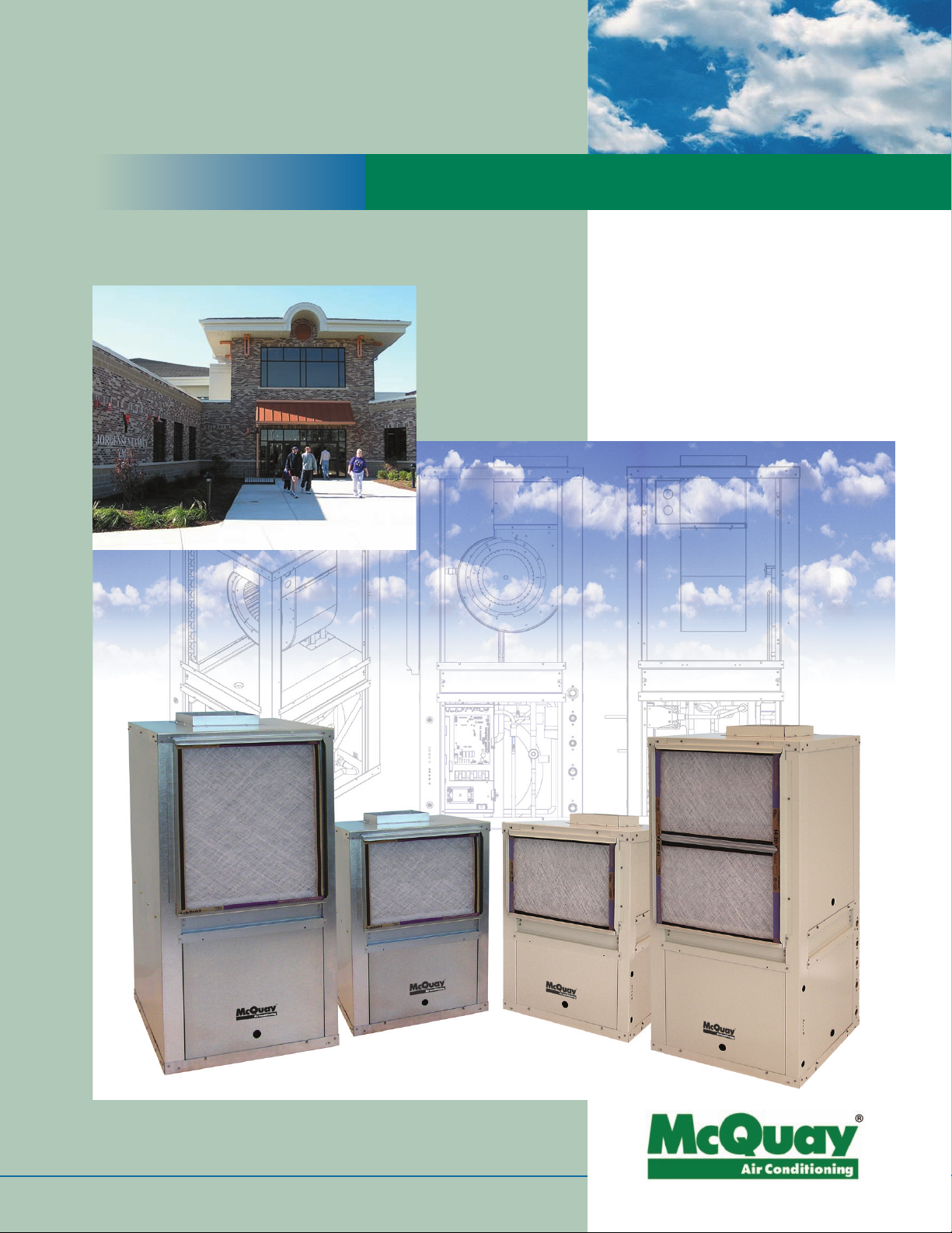
Flexible, High Efficiency Cooling and Heating Solutions.
™
Enfinity
Vertical Water Source
Heat Pumps
Standard Range – Model VFC
Geothermal Range – Model VFW
Engineered for flexibility and performance
™
Page 2
™
Water Source Heat Pumps
With Enfinity Water Source Heat
Pumps You Benefit From:
■
High efficiency, low operating costs.
■
R-410A refrigerant with no ozone
depletion potential or phase-out date.
■
Easy, low cost design and
installation.
■
Open Choices™ controls feature
allows easy, low cost integration
with a Building Automation System
(BAS) of your choice.
■
Boiler/tower or geothermal
application flexibility.
■
Integral electric heat coil for
supplemental electric heat.
More than 30 years ago, McQuay designed the rst complete
line of water source heat pumps for high efciency, individually-
zoned comfort control in ofces, schools, assisted living
facilities, manufacturing facilities and other commercial
buildings. Our reputation for outstanding reliability and quiet
operation has been reinforced in thousands of successful
installations.
Ennity water source heat pumps incorporate the best of our
past and the best of what’s new. Using feedback from building
owners, consulting engineers, contractors and service engineers,
we designed Ennity products to give you maximum exibility
to design, install, operate and maintain the ideal water source
heat pump system for your building project. And we incorporated non-ozone depleting R-410A refrigerant, which–along
with high Energy Efciency Ratios (EER’s)–helps preserve our
environment and precious energy resources.
■
Desuperheater (optional) reduces
energy required to produce domestic
hot water and may eliminate
requirement for separate water
heating equipment.
■
Hot Gas Reheat (optional) helps
improve comfort in the conditioned
space. During dehumidification mode,
the return air is cooled and dried over
the evaporator coil and then reheated
through the hot gas reheat coil to
maintain space temperature setpoint.
ommon Applications:
C
●
Indoor swimming facilities, locker
rooms.
●
Units pulling outside air for
ventilation requirements.
●
Computer rooms.
●
Auditoriums / Gymnasiums.
■
Quiet, reliable operation.
■
Easy, low cost maintenance
and service.
To learn how you can take advantage of the benets of
McQuay Ennity water source heat pumps on your next new
building or replacement project, contact your local McQuay
Representative or visit www.mcquay.com.
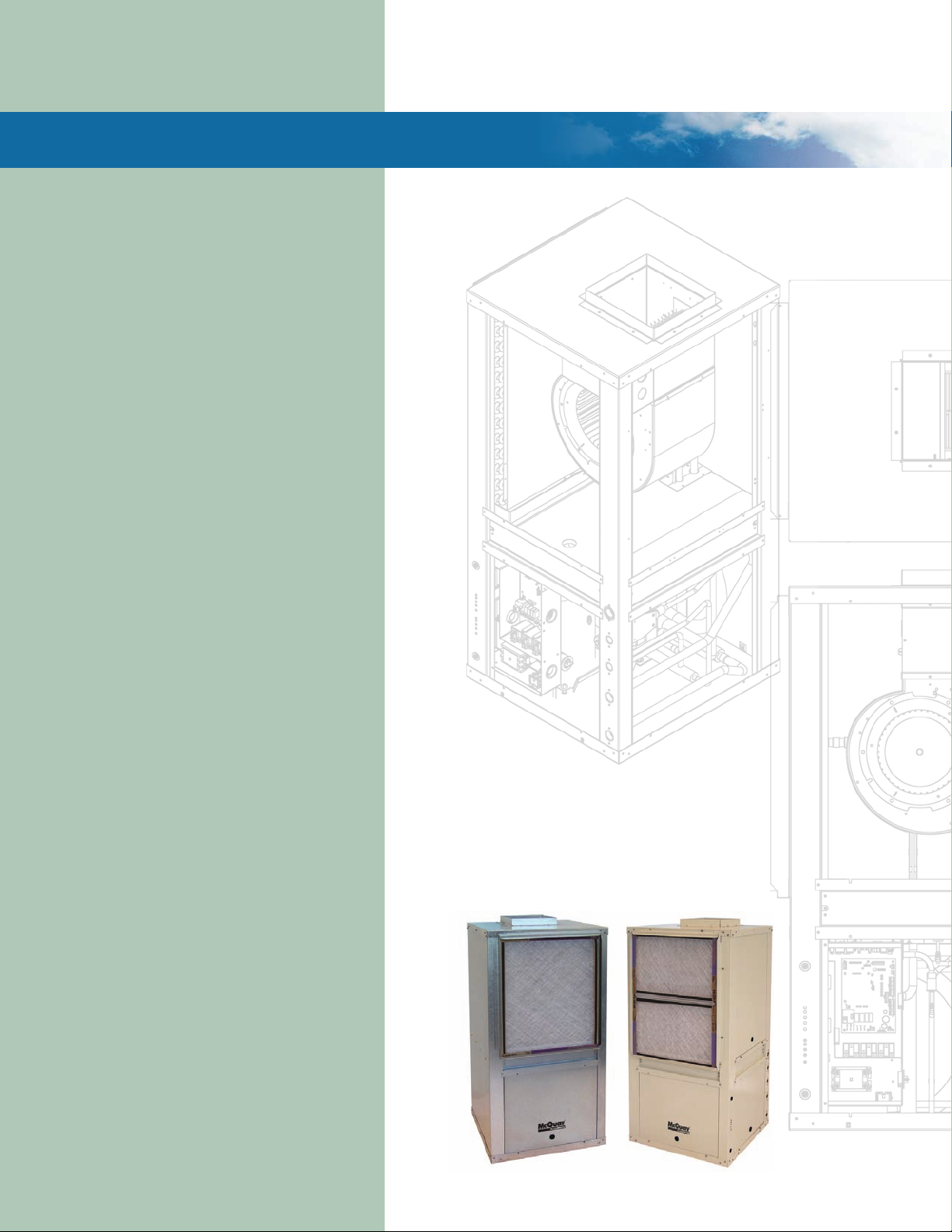
5 Cabinet Sizes – G-60 Galvanized or Pre-painted (Optional)
1/2 to 6 ton – Size *007 through 070
Model VFC (Standard Range: 55ºF to 110ºF)
Model VFW (Extended Range/Geothermal: 30ºF to 110ºF)
* Unit size 007 not available at time of publication. Please contact your local
McQuayrepresentativeforspecicavailability.
■
Painted cabinet – ideal for
residential applications.
2
Page 3
Save Energy & Reduce Design, Installation, Operating Costs
Owner, Engineer and Contractor Benefits
The Building Owner
■
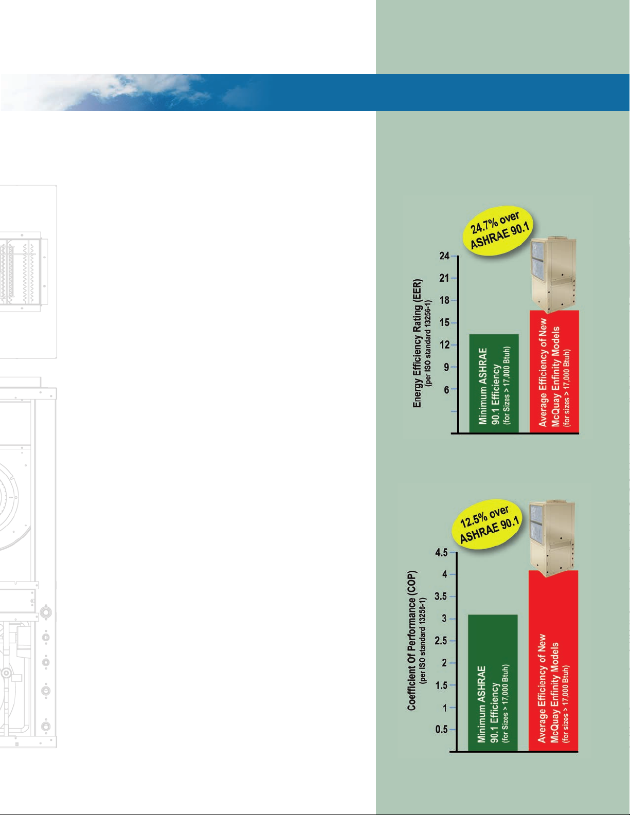
High efciency units reduce energy consumption/operating costs
and can contribute to earning points toward LEED® certication.
■
Open Choices control feature gives you the exibility to select
standalone thermostat operation or easy, low cost integration with
the BAS of your choice using an add-on communication module.
■
R-410A refrigerant has no ozone depletion potential or phase-
out date, helping to minimize environmental impact and protect
against refrigerant availability issues over the economic life of
your equipment investment.
■
Large fan wheel, quiet compressor selections and low vibration
design promote quiet operation.
■
Double-sloped polymer drain pan and optional closed cell insula-
tion promote superior indoor air quality.
■
Durable construction promotes long life, reliable operation.
The Engineer
■
Boiler/tower or geothermal unit selections provide flexibility in
designing the system that best meets the performance and budget
requirements of your project.
■
Multiple configurations reduce design time and cost by allowing
you to avoid obstructions and use minimum ductwork.
■
Multiple features and options (ECM motor, desuperheater, hot gas
reheat, integral electric heat, painted cabinet) give you the flexibility to select units that closely match application requirements.
Exceeds ASHRAE 90.1
Efficiency Requirements
Ground Loop – Cooling
Ground Loop – Heating
Installing Contractor / Service Personnel
■
Small footprint design makes it easier to meet space requirements
of new construction and replacement applications.
■
Flush FTP water fittings save time in making water connections
using one wrench.
■
Factory-installed filter rack saves time and expense to field-install
a filter rack.
■
External LED status lights allow quick troubleshooting – no need
to open up the unit.
■
Easy access to the unit compressor (2-sides), fan section (1-side),
motor (1-side) and unit controls (front access).
■
A removable orifice ring allows the blower and motor to be re-
moved without removing the blower housing or disconnecting the
unit from the ductwork.
3
Page 4
Flexible Design with Added Features
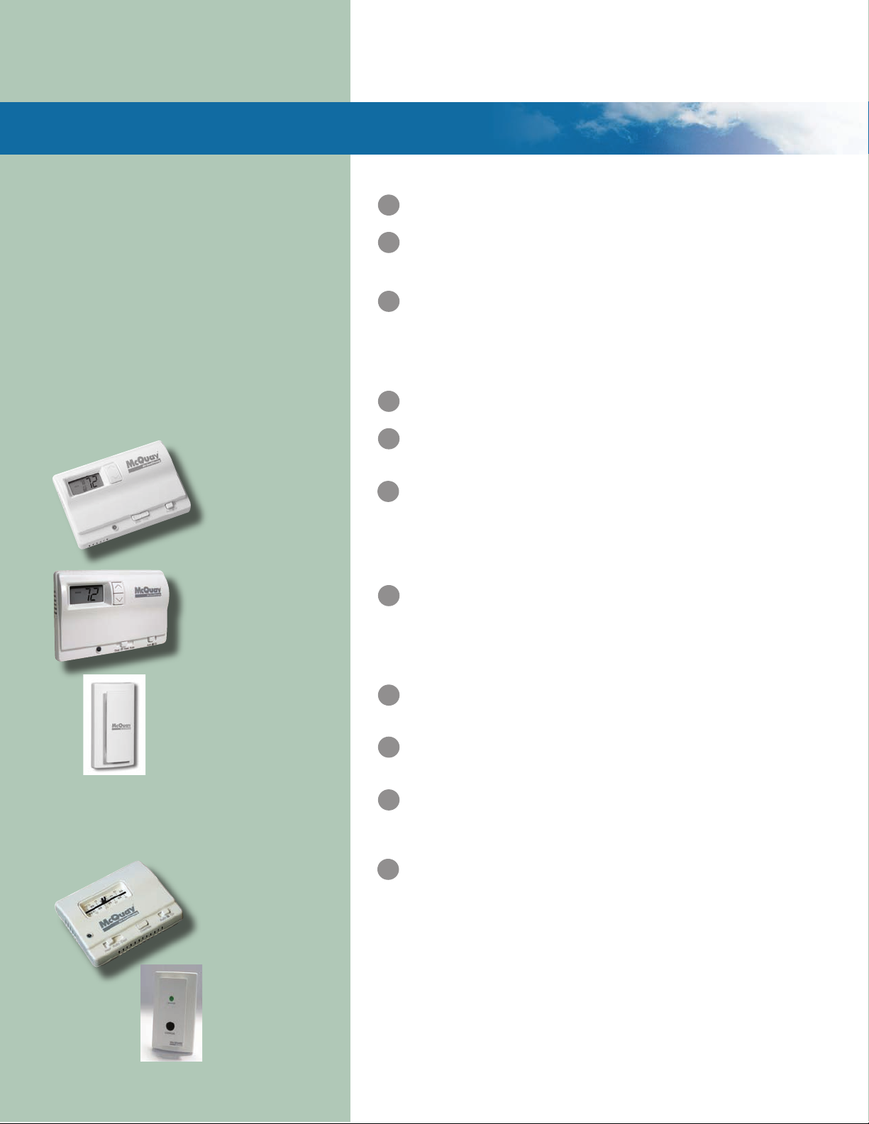
Wall Thermostats and Wall Sensors
Easy-to-operate comfort command
centers provide a complete range of
deluxe features. Choose between a 7-day
programmable or a non-programmable
thermostat for temperature control to match
your application, provide convenience
and help save energy and money. Three
wall temperature sensors are available;
sensor with tenant override, with set point
adjustment (55° to 95°F) and wall sensor
with setpoint adjustment (-3° to +3°F).
Two-Stage Heat/TwoStage Cool, 7-Day
Programmable Electronic
Thermostat
Auto or Manual Changeover
Two-Stage Heat/Two-Stage
Cool, Nigh Setback Override
Non-Programmable
Electronic Thermostat
Remote Sensor
667720401
(Used with wall mounted thermostat)
Room Temperature Sensors
• Set Point Adjustment (55° to 95°F)
• Set Point Adjustment (-3° to +3°F)
Sensor 668900801
•
Set Point Adjustment
• LED
• Override feature
Sensor 669088101
•
Status LED
• Override Button
Electric Heat (Optional) – Integral electric heat coil provides
1
supplemental or emergency heat when conditions require.
Electronically Commutated Motor (ECM-Optional) – ECM motor provides
2
quiet, efcient operation while maintaining constant CFM over its static
operating range. Factory programmed for 3-speeds.
3
MicroT
LED
4
Compact Cabinet – The standard unit is constructed of unpainted G-60
5
Desuperheater (Optional) – Saves energy by producing domestic hot
6
Filter & Filter Rack – Units come standard with a 1" (25.4 mm) thick
7
Removable
8
9
Piping Connections – Water connections are FPT water ttings, ush
10
Coaxial Heat Exchanger – Designed for maximum heat transfer at normal
Hot Gas Reheat Coil – Optional coil provides superior humidity control
11
2-W
ech® III Unit Controller – Designed for exibility, the main control
board is used in standalone applications. An optional I/O expansion
module can be used to control electric heat and multiple fan speeds. A
separate LonWorks® or BACnet® communication module can be easily
snapped onto the board to accommodate the building automation system
of your choice.
Annunciator – External LED status lights display fault conditions to
provide easy troubleshooting and diagnosis.
galvanized steel, with the smallest possible footprint. Optional painted
cabinet is ideal for aesthetic requirements of residential applications.
water using a small heat exchanger and water pump located in the
compressor compartment. Superheated refrigerant gas from the
compressor, which would otherwise be wasted, is used to heat water.
This reduces the amount of additional energy required to heat water and
it may eliminate the requirement for separate water heating equipment.
throwaway lter mounted in a 4-sided combination lter rack and return
air duct collar. This eliminates the added labor and cost to eld-mount
brackets. Filters can be easily removed from any side. A 2" lter rack is
available as a factory-installed selectable option to accept higher
efciency lters
Access Panels – Two front panels provide easy access to the
blower motor and unit controls. Two rear panels provide easy access to
the fan housing and compressor section.
with the outside of the cabinet for easy one-wrench connection to units.
A large condensate connection provides proper condensate removal.
and low water ow rates with minimum pressure drop. The inside tube
is deeply uted to enhance heat transfer and minimize fouling. A cupronickel heat exchanger is available as a selectable option.
for occupant comfort. Uses expelled heat from the refrigeration cycle
and redirects it through an isolated circuit in the evaporator section. For
every 10°F of temperature rise across the hot gas reheat coil there is
approximately a 20% drop in the discharge air relative humidity (%Rh).
A wall-mounted humidistat must be used in conjunction with the unit to
measure and adjust the humidity setpoint in the space.
ay Motorized Isolation Valve (Optional - Not Shown) –
Control valve can be factory-installed or eld-installed to handle
variable speed pumping requirements. Both standard and high cut-off
pressure valves are available as a selectable option.
4
Page 5

Features and Benefits
2" Filter Rack for High Efficiency
Filters & Easy Tooless Removal (Optional)
I/O Expansion Module
LonWorks & BACnet
MicroTech III
Unit Controller
Desuperheater – Heat Exchanger and
Water Pump Piping Circuit (Optional)
Communication Modules
Hot Gas Reheat Coil & Piping Circuit (Optional)
5
Page 6

®
MicroTech
Page Headline Here Page Headline Here
III Unit Controller – A Complete Control Solution
MicroTech III Unit Controller
The MicroTech III unit controller is a standalone microprocessor-based control board conveniently
located in the unit control box for accessibility. The board is designed to provide standalone control
of a Water Source Heat Pump using a wall thermostat or a wall-mounted temperature sensor.
Each unit controller is factory programmed, wired, and tested for complete control of single zone,
standalone operation of your McQuay Water Source Heat Pump.
Each unit controller orchestrates the following unit operations:
Enable heating and cooling to maintain setpoint Monitor discharge air temperature
based on a room sensor Monitor leaving water temperature
Enable fan and compressor operation Relay status of all vital unit functions
Monitor all equipment protection controls Support optional control outputs
MicroTech III
Unit Controller
I/O Expansion Module
For added functionality, an optional I/O expansion module interconnects to the
MicroTech III unit controller.
Adding an I/O Expansion Module (with an interconnect cable) allows for:
Monitoring of entering water temperature for boilerless electric heat control
Outputs for optional electric heat
I/O Expansion Module
®
LonWorks
The MicroTech III unit controller can accept a plug-in LonWorks communication module to provide
network communications and added functionality to easily integrate with an existing BAS.
The communication module can be factory- or eld-installed and is tested with all logic required to
monitor and control the unit.
The LonWorks communication module is LonMark 3.4 certied for BAS integration to provide
centralized scheduling and management of multiple heat pumps.
An amber, on-board status LED indicates the status of the MicroTech III LonWorks module.
Communication Module
BACnet® Communication Module
The MicroTech III unit controller can accept a plug-in BACnet
communication module to provide network communications and added
functionality to easily integrate with an existing BAS.
The communication module can be factory- or eld-installed and is
tested with all logic required to monitor and control the unit.
It is designed to be linked with a centralized building automation
system (BAS) through a BACnet communications network for
centralized scheduling and management of multiple heat pumps.
BACnet
Communication Module
LonWorks
Communication Module
External LED status lights - allow
6
quick troubleshooting
Page 7

Network Communication - with
L
onWorks or BACnet
communication module
Typical VFC Closet Installation
1 Discharge air
2 Acoustic thermal duct lining - 10 feet
3 Line voltage disconnect
4 Low voltage control wiring to unit control box
5 Flexible duct collar
6 Louvered closet door
7 Condensate drain
8 Flexiblereturnhosewithowcontroller/ballvalve
9 Flexible supply hose with Y-strainer/ball valve
10 Access to unit control box
11 LED annunciator lights indicate unit operation status and
faults
12 Fullvibrationisolationpadbetweenunitandoor
13 Minimum distance between return air duct collar and wall for
non-ducted return applications
• Size 007-012 – 4 inches
• Size 015-024 – 5 inches
• Size 030-036 – 6 inches
• Size 042-048 – 8 inches
7
Page 8

Dimensional Data
Page Headline Here Page Headline Here
Left Hand and Right Hand Return
Left and Right Hand Return determined by facing the water connection side of the unit – Unit size 015 thru 024 dimensional drawing shown.
Top View – Left Hand Top View – Right Hand
Overall Unit Dimensions
UNIT SIZE Dimensions
*
007 – 012
015 – 024
030 – 036
042 – 048
060 – 070
Note: Dimensions are approximate.
22¼"D x 20"W x 37"H
24¼"D x 23"W x 46½"H
24¼"D x 23"W x 50½"H
32½"D x 25"W x 46½"H
32½"D x 25"W x 58½"H
Left Hand Return
Low Voltage
7/8" (22mm)
Hole
Line Voltage
7/8" (22mm) Hole
Filter (Side) View Right Hand Return
Condensate
Drain Connection
Desuperheater
Water Return
Desuperheater
Water Supply
Water Return
Low
Voltage
7/8"
(22mm)
Hole
Line
Voltage
7/8"
(22mm)
Hole
Water Supply
Desuperheater
Water Return
Desuperheater
Water Supply
Water Return
Water Supply
Dimensions
Unit Size A B C D E F (Left Hand) F (Right Hand) G H J K M
*007 – 012
015 – 024
(616mm) (584mm) (238mm) (264mm) (189mm) (265mm) (135mm) (483mm) (67mm) (1181mm) (578mm)
030 – 036
(616mm) (584mm) (238mm) (264mm) (189mm) (265mm) (135mm) (483mm) (67mm) (1283mm) (680mm)
042 – 048
(826mm) (635mm) (337mm) (349mm) (245mm) (245mm) (143mm) (737mm) (45mm) (1181mm) (578mm)
060 – 070
(826mm) (635mm) (337mm) (349mm) (245mm) (245mm) (143mm) (737mm) (45mm) (1486mm) (883mm)
Notes:
Dimensionsareapproximate.“M”dimensionincludesductange.
* Not available at time of publication. Please consult your McQuay Representative for specific availability.
22¼" 20" 9½" 5"
(508mm) (241mm) (127mm) (162mm) (118mm) (265mm) (483mm) (41mm) (940mm) (476mm) 2
(565mm)
24¼" 23" 9⅜" 10⅜" 77/16" 107/16" 55/16" 19" 2⅝" 46½" 22¾"
24¼" 23" 9⅜" 10⅜"
32½" 25" 13¼" 13¾"
32½" 25" 13¼" 13¾"
6⅜" 4⅝" 107/16" 19" 1⅝" 37" 18¾"
77/16" 107/16" 55/16" 19" 2⅝" 50½" 26¾"
9⅝" 9⅝" 5⅝" 29" 1¾" 46½" 22¾"
9⅝" 9⅝" 5⅝" 29" 1¾" 58½" 34¾"
8
1
11
11
1
2
11
1
2
11
1
2
11
1
11
2
Condensate
Drain
Connection
/16" (43mm)
/16" (68mm)
11
/16" (43mm)
11
/16" (68mm)
/16" (43mm)
11
/16" (68mm)
/16" (43mm)
11
/16" (68mm)
/16" (43mm)
/16" (68mm)
Page 9

ISO Performance Data
Water Loop
Water Loop Performance Data Rated in Accordance with ISO Standard 13256-1 Boiler/Tower
Standard Unit ECM at High Static
Size
*007
009
012
015
019
024
030
036
042
048
060
070
* Not available at time of publication. Please consult your McQuay Representative for specific availability.
n/a – ECM option not available in unit sizes 007, 009, 012.
Unit
CFM
*
300
400
500
600
800
1000
1300
1400
1600
2000
2160
Airow Waterow
Voltage
Cooling Heating Cooling Heating
L/S GPM L/S Btuh Watts EER COP Btuh Watts COP Btuh Watts EER COP Btuh Watts COP
115-1-60
*
142
189
236
283
378
472
614
661
755
944
1019
*
2.3
3.0
3.6
4.68
5.81
7.25
9.50
11.00
12.00
15.50
19.00
*
0.15
0.19
0.23
0.30
0.37
0.46
0.60
0.69
0.76
0.98
1.20
208/230-1-60
265-1-60
230-1-50
115-1-60
208/230-1-60
265-1-60
230-1-50
115-1-60
208/230-1-60
265-1-60
230-1-50
208/230-1-60
265-1-60
230-1-50
208/230-1-60
265-1-60
230-1-50
208/230-1-60
265-1-60
230-1-50
208/230-1-60
265-1-60
208/230-3-60
230-1-50
208/230-1-60
208/230-3-60
460-3-60
380-3-50
208/230-1-60
208/230-3-60
460-3-60
575-3-60
380-3-50
208/230-1-60
208/230-3-60
265-1-60
460-3-60
575-3-60
230-1-50
380-3-50
208/230-1-60
208/230-3-60
265-1-60
460-3-60
575-3-60
230-1-50
380-3-50
208/230-3-60
460-3-60
575-3-60
380-3-50
*
9060
12000
14700
19200
23800
30000
39500
43900
48100
63200
75400
*
2650
3510
4300
5620
6980
8800
11500
12800
14100
18500
22100
*
*
*
14.0
14.4
16.0
15.2
15.1
17.0
14.8
15.0
14.7
15.1
13.5
4.1
4.2
4.7
4.5
4.4
5.0
4.3
4.4
4.3
4.4
4.0
10600
14000
16100
18300
26700
33400
45000
52500
56800
68300
87300
*
*
4.7
3110
4.8
4110
5.1
4720
4.4
5370
4.9
7820
5.2
9780
4.6
13200
4.8
15400
4.8
16600
4.7
20000
4.4
25500
n/a
n/a
n/a
*
19500
24100
29900
39900
44200
48700
63600
76200
n/a
n/a
n/a
*
5710
7050
8750
11700
12900
14200
18600
22300
n/a
n/a
n/a
16.6
16.3
17.0
15.0
16.2
16.0
15.7
14.0
n/a
n/a
n/a
n/a
n/a
n/a
*
*
4.9
4.8
5.0
4.4
4.7
4.7
4.6
4.1
*
18000
26300
33400
44500
52300
56400
67700
86300
n/a
n/a
n/a
*
5270
7700
9780
13000
15300
16500
19800
25300
n/a
n/a
n/a
*
4.6
5.2
5.4
4.6
5.1
5.1
5.0
4.5
9
Page 10

ISO Performance Data
Page Headline Here Page Headline Here
Ground Loop
Ground Loop Performance Data Rated in Accordance with ISO Standard 13256-1 Ground Coupled
Standard Unit ECM at High Static
*007
012
* Not available at time of publication. Please consult your McQuay Representative for specific availability.
n/a – ECM option not available in unit sizes 007, 009, 012.
Unit
Size
009
015
019
024
030
036
042
048
060
070
CFM
*
300
400
500
600
800
1000
1300
1400
1600
2000
2160
Airow Waterow
Cooling Heating Cooling Heating
Voltage
L/S GPM L/S Btuh Watts EER COP Btuh Watts COP Btuh Watts EER COP Btuh Watts COP
115-1-60
*
0.15
0.19
0.23
0.30
0.37
0.46
0.60
0.69
0.76
0.98
1.20
208/230-1-60
265-1-60
230-1-50
115-1-60
208/230-1-60
265-1-60
230-1-50
115-1-60
208/230-1-60
265-1-60
230-1-50
208/230-1-60
265-1-60
230-1-50
208/230-1-60
265-1-60
230-1-50
208/230-1-60
265-1-60
230-1-50
208/230-1-60
265-1-60
208/230-3-60
230-1-50
208/230-1-60
208/230-3-60
460-3-60
380-3-50
208/230-1-60
208/230-3-60
460-3-60
575-3-60
380-3-50
208/230-1-60
208/230-3-60
265-1-60
460-3-60
575-3-60
230-1-50
380-3-50
208/230-1-60
208/230-3-60
265-1-60
460-3-60
575-3-60
230-1-50
380-3-50
208/230-3-60
460-3-60
575-3-60
380-3-50
*
9720
12700
15700
19400
24800
30700
40300
45400
51600
65100
76500
*
2850
3720
4600
5690
7260
9000
11800
13300
15100
19100
22400
*
*
16.7
16.9
19.6
17.3
17.7
19.1
17.3
17.0
15.8
16.3
13.7
4.9
5.0
5.7
5.1
5.2
5.6
5.1
5.0
4.6
4.8
4.0
*
7020
9300
10000
13700
17800
22300
30300
35100
40300
47000
58900
2050
2720
2920
4010
5210
6530
8900
10300
11800
13700
17200
*
*
3.3
3.5
3.5
3.5
3.6
3.9
3.4
3.6
3.4
3.5
3.1
n/a
n/a
n/a
*
19700
25100
30600
40500
46100
50200
66000
78400
n/a
n/a
n/a
*
5770
7350
8960
11800
13500
14700
19300
22900
n/a
n/a
n/a
19.0
19.2
19.3
16.6
18.9
18.2
18.0
16.2
n/a
n/a
n/a
*
*
5.6
5.6
5.7
4.9
5.5
5.3
5.3
4.7
n/a
n/a
n/a
*
13400
17500
22300
30000
34400
37600
46000
56800
n/a
n/a
n/a
*
3920
5120
6530
8790
10100
11000
13500
16600
142
189
236
283
378
472
614
661
755
944
1019
*
*
2.3
3.0
3.6
4.68
5.81
7.25
9.50
11.00
12.00
15.50
19.00
n/a
n/a
n/a
*
3.7
3.8
4.0
3.3
3.8
3.8
3.8
3.6
10
Page 11

ISO Performance Data
Ground Water
Ground Water Performance Data Rated in Accordance with ISO Standard 13256-1
Standard Unit ECM at High Static
Size
*007
009
012
015
019
024
030
036
042
048
060
070
* Not available at time of publication. Please consult your McQuay Representative for specific availability.
n/a – ECM option not available in unit sizes 007, 009, 012.
Unit
CFM
*
300
400
500
600
800
1000
1300
1400
1600
2000
2160
Airow Waterow
Cooling Heating Cooling Heating
Voltage
L/S GPM L/S Btuh Watts EER COP Btuh Watts COP Btuh Watts EER COP Btuh Watts COP
115-1-60
*
142
189
236
283
378
472
614
661
755
944
1019
*
2.3
3.0
3.6
4.68
5.81
7.25
9.50
11.00
12.00
15.50
19.00
*
0.15
0.19
0.23
0.30
0.37
0.46
0.60
0.69
0.76
0.98
1.20
208/230-1-60
265-1-60
230-1-50
115-1-60
208/230-1-60
265-1-60
230-1-50
115-1-60
208/230-1-60
265-1-60
230-1-50
208/230-1-60
265-1-60
230-1-50
208/230-1-60
265-1-60
230-1-50
208/230-1-60
265-1-60
230-1-50
208/230-1-60
265-1-60
208/230-3-60
230-1-50
208/230-1-60
208/230-3-60
460-3-60
380-3-50
208/230-1-60
208/230-3-60
460-3-60
575-3-60
380-3-50
208/230-1-60
208/230-3-60
265-1-60
460-3-60
575-3-60
230-1-50
380-3-50
208/230-1-60
208/230-3-60
265-1-60
460-3-60
575-3-60
230-1-50
380-3-50
208/230-3-60
460-3-60
575-3-60
380-3-50
*
10900
14100
17100
21400
26600
33000
42900
48800
56100
69000
79100
*
3200
4130
5010
6270
7790
9600
12500
14300
16400
20200
23100
*
8820
*
2580
3450
3830
4950
6360
8320
11000
12500
14300
17100
21300
*
4.0
4.2
4.3
4.1
4.2
4.6
4.1
4.2
4.0
4.1
3.6
*
*
23.8
23.8
28.1
23.5
23.3
25.1
22.3
22.1
20.3
20.5
16.6
7.0
7.0
8.2
6.9
6.8
7.4
6.5
6.5
5.9
6.0
4.9
11800
13100
16900
21700
28400
37700
42900
48900
58400
72700
n/a
n/a
n/a
*
21600
26900
32900
43000
49100
54300
69900
80600
n/a
n/a
n/a
*
6320
7880
9630
12600
14400
15900
20500
23600
n/a
n/a
*
26.1
25.8
25.5
21.3
24.8
23.8
22.9
19.6
n/a
n/a
n/a
7.7
7.6
7.5
6.2
7.3
7.0
6.7
5.7
n/a
n/a
n/a
*
16600
21300
28400
37400
43000
47100
57400
70500
n/a
n/a
n/a
n/a
n/a
n/a
n/a
*
*
4860
6240
8300
10900
12600
13800
16800
20600
*
4.4
4.5
4.8
4.0
4.5
4.5
4.4
4.1
11
Page 12

Water Source Heat Pump Geothermal Systems
Water source heat pump
systems are one of the
most efficient systems
available for heating and
cooling buildings. High
efficiency, self-contained
McQuay Enfinity units can
be placed in virtually any
location within a building.
Each unit responds only
to the heating or cooling
load of the individual zone
it serves. This provides
excellent comfort levels for
occupants, better control
of energy use for building
owners and lower seasonal
operating costs.
Boiler/Tower Loop
A “Boiler/Tower” application uses a simple
two pipe water circulating system that adds
heat, removes heat or transfers rejected
heat to other units throughout the building.
The water temperature for heating is usually
provided by a natural gas or electric boiler
located in a mechanical room. The condensing water temperature is provided by a cooling tower that dissipates waste heat. This
application can be the lowest cost of the
loop options available.
Open Loop “Well Water”
“Open Loop” well water systems use
ground water to remove or add heat to
the interior water loop. The key benefit
of an open loop system is the constant
water temperature, usually 50°F to 60°F,
which provides efficient operation at a
low first cost. Open Loop applications are
commonly used in coastal areas where
soil characteristics allow reinjection wells
to return the water back to the aquifer.
Reinjection wells must be approved by the
U.S. Environmental Protection Agency.
Non-Ozone Depleting
R-410A Refrigerant
A global leader in
system solutions for
air conditioning, heating,
ventilating and refrigeration.
(800) 432-1342
www.mcquay.com
Geothermal Closed Loop
Vertical loops (shown) are installed by
drilling vertical bore holes into the earth
and inserting a plastic polyethylene supply/
return pipe into the holes. Horizontal loops
are installed in trenches approximately 5
feet below the ground surface. Both
vertical and horizontal loops extract the
Earth’s natural heat and reject it back.
McQuay International delivers engineered, flexible solutions for commercial, industrial and institutional
HVAC requirements with reliable products, knowledgeable applications expertise and responsive support. McQuay products and services are provided through a worldwide network of dedicated sales
and service offices.
™ ® The following are trade names or registered trademarks of their respective companies:
LonTalk and LonMark from Echelon Corporation, BACnet from ASHRAE and Enfinity from McQuay
International.
Products Manufactured in an ISO Certified Facility.
Surface Water or Lake Loop
A “Surface Water” or “Lake” (shown) closed
loop system is a geothermal loop that is
directly installed in a lake or body of water
that is near the building. In many cases, the
body of water is constructed on the building
site to meet run-off or aesthetic requirements. The size and the depth of the lake
is critical, and commercial design services
should be used to certify that a given body
of water is sufficient for building loads.
© 2009 McQuay International
A/SP 31-249 (3/09)
 Loading...