

Page 1

Installation, Operation and Maintenance Manual
Variable Frequency Drive
For Centrifugal Chillers
MicroTech 200
MicroTech II
IOMM VFD
Group: Chiller
Part Number: 736015429
Effective: January 2003
Supercedes: New
Page 2

Table of Contents
g
Introduction............................................................................................................4
General Description...............................................................................................5
Codes/Standards............................................................................................................................5
Quality Assurance.........................................................................................................................5
Nomenclature................................................................................................................................5
Definition of Terms ................................................................................................7
Parameters.....................................................................................................................................8
Service Conditions........................................................................................................................8
Standard Features..........................................................................................................................8
Cooling Requirements for VFDs ..........................................................................9
VFD Dimensional Diagrams...............................................................................11
MicroTech 200 VFD Control...........................................................................15
VFD Chiller Control States.........................................................................................................15
Control Sequence, MicroTech 200......................................................................16
WDC, Dual Compressor VFD Operation....................................................................................17
MicroTech 200 Controller VFD Menu Screens..........................................................................17
MicroTech II VFD Control..............................................................................23
General Description:...................................................................................................................23
Sequence of Operation................................................................................................................24
Interface Panel Screens...............................................................................................................25
VFD Components and Locations .......................................................................29
Regulator Board Description.......................................................................................................32
Using the VFD Keypad/Display..........................................................................33
Monitor Mode.............................................................................................................................34
The Display.................................................................................................................................35
The Keypad.................................................................................................................................36
Drive Status LEDs.......................................................................................................................38
Optional Line Reactors .......................................................................................39
Troubleshooting the Drive Using Error Codes..................................................40
Identifying Alarm Codes and Recovering...................................................................................41
Identifying Fault Codes and Recovering.....................................................................................42
Accessing, Reading, and Clearing the Faults in the Error Log ....................................................45
“McQuay" is a registered trademark of McQuay International
"Information and illustrations cover the McQuay International products at the time of publication and we reserve the right to make changes
in desi
2 IOMM VFD
2003 McQuay International
n and construction at anytime without notice".
Page 3
DANGER
Only qualified electrical personnel familiar with the construction and operation of this
equipment and the hazards involved should install, adjust, operate, or service this
equipment. Read and understand this manual and other applicable manuals in their
entirety before proceeding. Failure to observe this precaution could result in severe bodily
injury or loss of life.
DANGER
DC bus capacitors retain hazardous voltages after power has been disconnected. After
disconnecting input power to the unit, wait five (5) minutes for the DC bus capacitors to
discharge, and then check the voltage with a voltmeter to ensure the DC capacitors are
discharged before touching any internal components. Failure to observe this precaution
could result in severe bodily injury or loss of life.
CAUTION
The user is responsible for conforming to all applicable local, national and international
codes. Failure to observe this precaution could result in damage to,
or destruction of the equipment.
WARNING
The drive contains printed circuit boards that are static-sensitive. Anyone who touches the
drive components should wear an anti-static wristband. Erratic machine operation and
damage to, or destruction of, equipment can result if this procedure is not followed.
Failure to observe this precaution can result in bodily injury.
IOMM VFD 3
Page 4
Introduction
WSC and WDC single and dual compressor chillers can be equipped with a Variable Frequency Drive
(VFD). A VFD modulates the compressor speed in response to load, evaporator pressure, and condenser
pressure, as sensed by the chiller microprocessor. Despite the small power penalty attributed to the
VFD, the chiller can achieve outstanding overall efficiency. VFDs are effective when there is a reduced
load, combined with a low compressor lift (lower condenser water temperatures), dominating the
operating hours.
The traditional method of controlling centrifugal compressor capacity is by inlet guide vanes. Capacity
can also be reduced by slowing down the compressor, thereby reducing the impeller tip speed.
However, sufficient impeller tip speed must always be maintained to meet the chiller’s discharge
pressure requirements. The speed control method is more efficient than guide vanes by themselves.
In actual practice, a combination of the two techniques is used. The microprocessor slows the
compressor (to a programmed minimum percent of full load speed) as much as possible, considering the
need for tip speed to make the required compressor lift. Then the guide vanes take over for further
capacity reduction. This methodology provides the optimum efficiency under any operating condition.
Inlet guide vanes control compressor capacity based on a signal from the microprocessor, which is
sensing changes in the leaving chilled water temperature. The guide vanes vary capacity by changing
the angle and flow of the suction gas entering the impeller. The impeller takes a smaller “bite” of the
gas. Reduced gas flow results in less capacity. Compressors start unloaded (guide vanes closed) in
order to reduce the starting effort. A vane-closed switch (VC) signals the microprocessor that the
compressor vanes are closed.
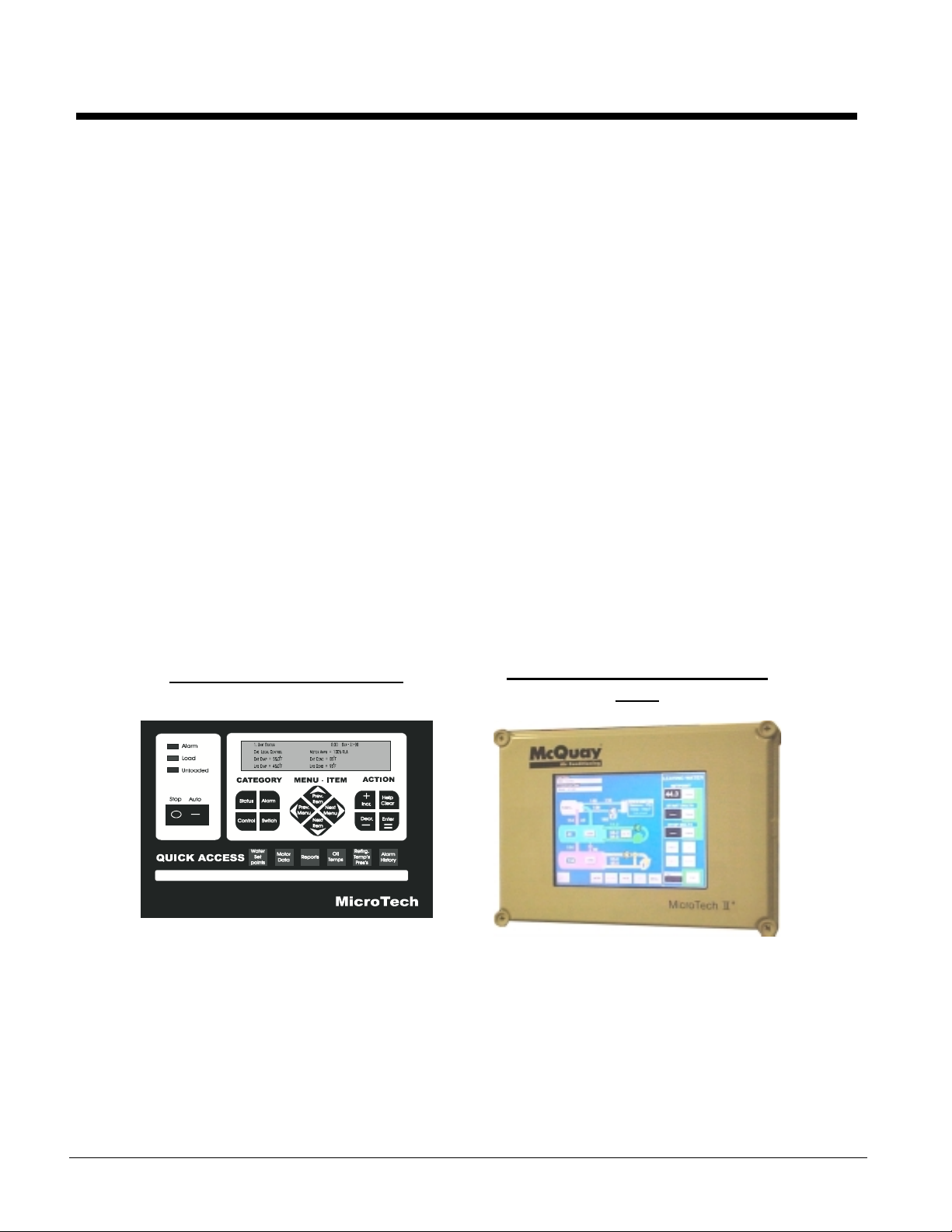
VFDs can be found on centrifugal chillers with the older MicroTech 200 controller (sometimes referred
to as MicroTech I or just plain MicroTech) or the newer MicroTech II controller. The two MicroTech
controller versions are easily differentiated as shown below.
MicroTech 200 Control Panel
MicroTech II Operator Interface
Panel
Operation and adjustment of the VFD involves settings on both the VFD itself and also to the chiller
controller, either MicroTech 200 controller or MicroTech II controller. This manual consists of a section
relating to VFD operation common to both chiller controllers and also separate sections for the settings
specific to either of the chiller MicroTech controllers.
NOTE: VFDs are programmed differently in the factory for 50 and 60 hertz applications. It is prudent
to verify this by checking the settings sticker in the unit and the actual unit settings using the Reliance
manual shipped with the VFD unit as a reference.
4 IOMM VFD
Page 5

General Description
The VFD will not generate damaging voltage pulses at the motor terminals when applied within 500 feet
of each other. The VFD drive complies with NEMA MG1 section 30.40.4.2, which specifies these
limits at a maximum peak voltage of 600 volts and a minimum rise time of 0.1 microseconds.
All VFDs require cooling. Models VFD 019 and VFD 025, which draw 240 amps or less, are aircooled. All others are water-cooled.
Factory-mounted water-cooled units have cooling water for the VFD combined with the compressor oil
cooling system.
Freestanding water-cooled units require field-installed chilled water supply and return piping for the
VFD.
Water-cooled VFD’s have a liquid-cooled heatsink assembly enabling liquid cooling of the drive though
a single inlet and outlet connection point, dissipating 25,000 Btus/Hr for 600HP, 20,000 Btus/Hr for 450
HP and 16,000 Btus/Hr for 350 HP. The cooling circuit maintains water temperature between 60°F and
104°F (15°C to 40°C).
There is a temperature-regulating valve located in the drive. It must be set to maintain 95°F (35°C)
leaving coolant temperature. This is necessary to prevent condensation from forming in the heatsink.
Codes/Standards
• VFDs are UL 508 listed
• VFDs are designed to comply with the applicable requirements of the latest standards of ANSI,
NEMA, National Electric Code (NEC), NEPU-70, IEEE 519-1992, FCC Part 15 Subpart J, CE 96.
Quality A ssurance
• Every VFD is functionally tested under motor load. During this test the VFD is monitored for
correct phase current, phase voltages, and motor speed. Correct current limit operation is verified
by simulating a motor overload.
• Scrolling through all parameters verifies proper factory presets. The computer port also verifies that
the proper factory settings are loaded into the drive.
• Every VFD’s heatsink is tested to verify proper embedding of the tubing for flow of coolant liquid.
Thermal tests are performed on the VFD to verify that the cooling occurs within the correct
temperature range.
Nomenclature
VFD XXX X X
Model Number
019 through 120
Mounting
M=Factory-mounted
L= Shipped Loose for Field Mounting
Cooling Method
A=Air-cooled
W=Water-cooled
IOMM VFD 5
Page 6
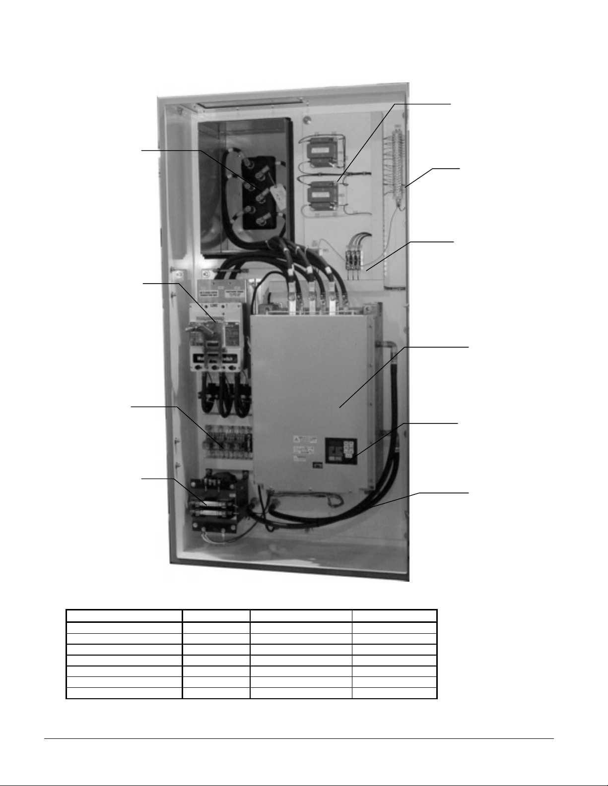
Figure 1, VFD Internal Components, Factory Mount ed, Water-Cooled M odel
Motor Terminals
Disconnect Switch
Optional Meter
Transformers (2)
Terminal Board
Fuses
Motor Control
Relays (MCR)
Control
Transformer
w/ Fuses
Table 1, VFD Model Sizes
VFD Model Max. Amps Power Cooling
VFD 019 170 3/60/460-480 Air
VFD 025 240 3/60/460-480 Air
VFD 047 414 3/60/460-480 Water
VFD 060 500 3/60/460-480 Water
VFD 072 643 3/60/460-480 Water
VFD 090 890 3/60/460-480 Water
VFD120 1157 3/60/460-480 Water
Drive Unit
Keyboard/Display
Cooling W ater
Lines
6 IOMM VFD
Page 7

Definition of Terms
Active LEWT Setpoint
Command Speed
Demand Limit
FVC
IGBT
Lift Temperature
Lift Temperature Control
Speed
Low evap pressure
inhibit setpoint
Manual Load Setpoint
Maximum Pulldown
Rate
MCR
Minimum Amp Setpoint
Minimum Rate Setpoint
Minimum Speed
Network Capacity Limit
Maximum capacity
allowed from an external
signal
Network Setpoint
OIM
PCB
PWM
Rapid Shutdown
RLA
RMI
Softloading
Speed
Stage Delta
SVC
the current Leaving Evaporator Water Temperature Setpoint
the speed command issued by the MicroTech controller to the VFD
the maximum amp draw as established by the Demand Limit setpoint
flux vector control
Insulated Gate Bi-polar Transistors
Saturated condenser refrigerant temperature minus saturated evaporator
temperature.
The minimum speed to maintain lift and avoid surge. The controller
continuously calculates the minimum operating speed in all modes, based
on the lift temperature.
the low evaporator pressure that inhibits any further compressor loading
MicroTech controller manual operation of the guide vanes for testing
maximum pulldown rate of chilled water in degrees per minute
motor control relay
MicroTech controller minimum unloading setpoint
pulldown rate for MicroTech 200 controller
the minimum speed allowed, usually set at 70%
chilled water setpoint from an external source
operator interface module
printed circuit board
pulse-width-modulated
if there is a fault, the MicroTech switches the state to VFD OFF. This
includes changing the Unit Control Panel switch to OFF.
, Rated Load Amps, the maximum motor amps
remote meter interface, located in the VFD panel
extended ramp-up in capacity, set in the MicroTech controller
speed signal to the compressor motor from the variable frequency drive
(VFD) based on analog output (0 – 10 VDC) from the MicroTech controller.
multi compressor (or dual compressor unit) on/off cycling temperature
delta-T
sensorless vector control
IOMM VFD 7
Page 8
Parameters
Throughout this manual, you will see references to parameter names and numbers that identify them for
the drive. This manual uses the same format that will be shown on the keypad/display to refer to
parameters:
P.nnn H.nnn R.nnn
Where: nnn is a number
P designates general parameters
H designates Volts/Hertz parameters
R designates optional RMI parameters
CAUTION
These parameters must never be changed from the startup values set by the McQuay
startup technician. Damage to the chiller or drive could occur.
Service Conditions
Input power: 380/460 VAC ±10%, 3 phase, 50/60 Hertz, ±5 Hz.
Ambient operating temperature range: 32°F to 104°F (0°C to 40°C), elevation up to 3300 feet (1000m)
altitude with a relative humidity to 95% non-condensing.
Storage temperature range: 50°F to 122°F (10°C to 50°C).
AC line distribution system capacity shall not exceed 85,000 amps symmetrical available fault current.
Standard Features
• Electronic overload circuit designed to protect an AC motor, operated by the VFD output, from
extended overload operation on an inverse time basis. This electronic overload is UL and NEC
recognized as adequate motor protection. No additional hardware, such as motor overload relays, or
motor thermostats are required.
• An LED display that digitally indicates:
Frequency output Input kW
Voltage output Elapsed time
Current output Time stamped fault indication
Motor RPM DC bus voltage
• The VFD is capable of maintaining operation through power dips up to 10 seconds without a
controller trip, depending upon load and operating conditions. In this extended ride-through, the
drive uses the energy generated by the load inertia of the motor as a power source for electronic
circuits.
• An isolated 0-20mA, 4-20mA, or 0-4, 0-8, 0-10 V analog speed input follower.
• An isolated 0-10V or 4-20mA output signal proportional to speed or load.
8 IOMM VFD
Page 9

• Standard I/O expansion interface card with the following features:
• Four isolated 24VDC programmable digital inputs
• One frequency input (0 to 200Hz) for digital control of speed or trim reference
• Four programmable isolated digital outputs (24 VDC rated)
• One Form A output relay rated at 250 VAC or 24VDC
• Two NO/NC programmable output relays rated at 250 VAC or 24 VDC
• The VFD includes the following standard protective circuit features:
• Output phase-to-phase short circuit condition
• Total ground fault under any operating condition
• High input line voltage
• Low input line voltage
• Loss of input or output phase
• External fault (This protective circuit will permit wiring to a remote normally closed equipment
protection contact to shut down the drive.)
• Metal oxide varistors for surge suppression are provided at the VFD input terminals.
Cooling Requirements for VFDs
VFD cooling water piping is factory-connected to the chiller’s oil cooling system on factory-mounted VFDs.
See Figure 2.
VFD cooling water piping must be field connected on freestanding VFDs. See Figure 3.
Figure 2, VFD (047 through 120) Cooling Water Piping for Factory-M ount ed VFD
*
STOP
*
CHILLED
WATER
PUMP
VALV E
*
STOP
VALVE
Field Supplied Piping Components
*
Field Piping
Connection Point
BALANCING
VALV E
*
STRAINER
MAX. 40 MESH
CHILLER
VFD HEAT
EXCHANGER
SOLENOID
VALV E
(Factory Mounted)
SOLENOID
VALV E
(Factory Mounted)
*
DRAIN VALVE
OR PLUG
COMPRESSOR
OIL COOLER CIRCUIT
WATER
REGULATING
VALVE
(Factory Mounted)
*
STOP
VALV E
WATER
REGULATING
VALV E
(Factory Mounted)
*
STOP
VALVE
See notes on next page.
IOMM VFD 9
Page 10

Figure 3, VFD (047 and Larger) Cooling Water Piping for Free-Standing VFD
*
CHILLED
WATER
PUMP
STOP
VALVE
*
STOP
VALVE
Field Supplied Piping Components
*
Field Piping
Connection Point
*
BALANCING
VALVE
*
STRAINER
MAX. 40 MESH
CHILLER
VFD HEAT
EXCHANGER
SOLENOID
VALV E
(Factory Mounted)
SOLENOID
VALV E
(Factory Mounted)
*
DRAIN VALVE
OR PLUG
COMPRESSOR
OIL COOLER CIRCUIT
WATER
REGULATING
VALV E
(Factory Mounted)
REGULATING
(Factory Mounted)
*
STOP
VALVE
WATER
VALVE
*
STOP
VALVE
Table 2, Cooling Requirements
McQuay
Drive Model
Number
Combined
Compressor Oil
and VFD Cooling
Copper Tube Size
Type K or L
VFD Cooling
Only Copper
Tube Size
Type K or L
Coolant
Method
Max.
Entering
Coolant
Temperature
(°°°° F)
VFD 019 N/A N/A Air 104 40 NA N/A
VFD 025 N/A N/A Air 104 40 NA N/A
VFD 047 1.0 7/8 in. Water (1) 90 40 10 (2) 300
VFD 060 1.0 7/8 in. Water (1) 90 40 30 (2) 300
VFD 072 1.0 7/8 in. Water (1) 90 40 30 (2) 300
VFD 090 1 1/4 1.0 in. Water (1) (3) 90 40 30 (2) 300
VFD 120 1 1/4 1.0 in. Water (1) (3) 90 40 30 (2) 300
Notes:
1. Cooling water must be from the closed, chilled water circuit with corrosion inhibitors for steel and copper, and must be piped across the
chilled water pump.
2. The required pressure drop is given for the maximum coolant temperature. The water regulating valve will reduce the flow when the
coolant temperature is below the maximum in the table. The pressure drop includes the drop across the solenoid valve, heat exchanger
and water regulating valve.
3. Models VFD 090and 120 have a separate self-contained cooling loop with a recirculating water pump and heat exchanger, but are piped
the same as all water-cooled VFDs.
Min.
Entering
Coolant
Temperature
(°°°° F)
Required
Pressure
Drop
feet
Maximum
Pressure
(Water Side)
psi
Table 3, Cooling Water Connection Sizes
Chiller Unit
Oil Cooler VFD Combined
WDC 100/126 1 1/2 in. FPT ¾ in. MPT 1 1/2 in. FPT
WSC/WDC 050 Not Required Air-Cooled Not Required
All Others 1 in. FPT 3/4 in MPT 1 in. FPT
Free-Standing VFD Factory-Mounted VFD
10 IOMM VFD
Page 11

VFD Dimensional Diagrams
m
Figure 4, VFD 019/025 (Air-Cooled)
8.0
(203.2)
Power Wiring
Entry Panel
6.0
(152.4)
2.0
(50.8)
14.0
(355.6)
Removable
Lifting Eyes
Note: Remove before drilling
to prevent metal particles fro
falling into drive components.
72.0
(1828.8)
VM
AM
36.0 (914.4)
19.1 (485.1)
IOMM VFD 11
Page 12

Figure 5, VFD 047 (Water-Cooled)
T
8.00
8.00
21.06
(534.92)
2.00 (50.8)
16.00
(406.4)
6.00
(152.4)
(203.2)
POWER WIRING
(203.2)
ACCESS PANEL
POWER WIRING
ACCESS PANEL
6.00
(152.4)
2.00 (50.8)
16.00
(406.4)
Removable
Lifting Eyes
Note: Remove before drilling
to prevent metal particles from
falling into drive components.
20.00
(508.0)
36.00
(914.4)
90.00
(228.6)
3.00
(76.2)
OUTLET
INLET
7.13
(181.1)
BOTH INLET AND OUTLET ARE 3/4 (19.1) NP
2.61 (66.3)
12 IOMM VFD
Page 13

Figure 6, VFD 060/072 (Water-Cooled)
12.0
6.0
(
)
3.0 (76.2)
12.0
(304.8)
(152.4)
(304.8)
POWER WIRING
ACCESS PANEL
12.0
(304.8)
POWER WIRING
ACCESS PANEL
60.0
(1524)
15.0
(381)
9.0
(228.6)
3.0 (76.2)
12.0
(304.8)
72.0
(1828.8)
Note: Remove before drilling
to prevent metal particles from
falling into drive components.
19.1
(485.1)
OUTLET VALVE
3/4 (19.1) NPT
INLET VALVE
3/4 (19.1) NPT
18.6
(473.2)
3.5
(88.9)
7.5
190.5
IOMM VFD 13
Page 14
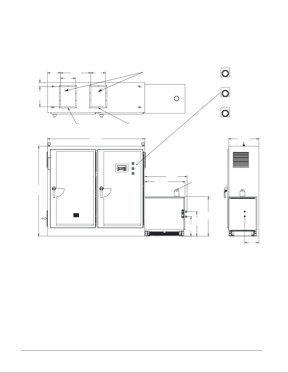
Figure 7, VFD 090/120 (Water-Cooled)
/
/
A
A
3.38
(85.8)
TYP
16.0
(406.4)
10.5
(266.7)
11. 9
(302.3)
24.3
(617.2)
11. 9
(302.3)
Note: Remove before drilling
to prevent metal particles from
falling into drive components.
POWER
ON
W
DRIVE
ULT
F
PUMP
MOTOR
RUNNING
B
(1828.8)
FAN
AIR
FLOW
72.0
LINE LEAD ACCESS
COVER PLATE
78.2
(1986.3)
MOTOR LEAD ACCESS
COVER PLATE
POWER
ON
W
DRIVE
FAULT
A
PUMP MOTOR
RUNNING
B
CLOSED LOOP
COOLING SYSTEM
32.4
(822.9)
34.1
(866.1)
WATER
RESERVOIR
CUSTOMER
OUTLET
INLET
3
4 " (19.1) NPT
19.6
(497.8)
15.6
(396.2)
31.6
(802.6)
24.2
(614.7)
OUTLET
INLET
11. 4
(289.6)
14 IOMM VFD
Page 15

MicroTech 200 VFD Co ntrol
The MicroTech 200 unit controller is wired to the variable frequency drive instead of to a motor starter.
The MicroTech controller provides the speed setpoint signal to a hardwired input on the VFD. The
output on the MicroTech AOX (auxiliary output) board is configured (using jumpers) to provide a 0-10
VDC signal to a hard wired analog input on a VFD.
There is no feedback signal required from the variable frequency drive to the MicroTech to indicate the
speed of the motor. The actual percent motor speed is within 1% of the analog output signal from the
MicroTech controller.
Digital Input, DI 10, is wired to a switch on the compressor that indicates when the vanes are 100%
open (VO switch). If the switch is open, the status of the vanes is Not Open. If the switch is closed, the
status of the vanes is Open.
VFD Chiller Control States
There are seven (7) VFD chiller control states and they are based on the unit status. See Table 5 on page
19 for relationships.
MicroTech: Menu 1, Screen 2
MicroTech 200
VFD Off
VFD Start
VFD Running: Adjust Speed & Open Vanes
VFD Running: Hold Mi nimum Speed & Adjust
Vanes
VFD Routine Shutdown
VFD Locked Speed
VFD Override Capacity Control
VFD Off: The VFD is turned off, the speed output is 0%, and the vanes are closed.
VFD Start: The VFD is turned on, the speed output is minimum speed, and the vanes are modulated to
maintain the leaving evaporator setpoint. (VFD running, hold minimum speed, and adjust vanes mode.)
VFD Running Adjust Speed & Open Vanes: The VFD remains on, the speed output is modulated to
maintain the leaving evaporator setpoint, and the vanes are pulsed to the open position. This mode
drives the vanes open and uses the speed to control capacity based on the evaporator leaving water
setpoint.
VFD Running Hold Minimum Speed & Adjust Vanes: The VFD remains on, the speed output is held
at Minimum Speed, and the vanes are modulated to maintain the evaporator leaving water setpoint. This
mode occurs when the load (tons) can be satisfied with the vanes not fully open while at minimum
speed. Decreasing speed can no longer reduce capacity, so the vanes maintain temperature control.
When the load increases, the vanes will pulse open until the vane open switch shows that the vanes are
full open. At this point, the MicroTech controller changes the mode to VFD Running: Adjust Speed and
Open Vanes.
VFD Routine Shutdown: The VFD remains on, the speed output remains the same, dependent on the
prior state, and the vanes are driven closed.
IOMM VFD 15
Page 16

VFD Locked Speed: The MicroTech has a VFD LOCKED Speed Setpoint that can be selected either
“ON” or “OFF” from the MicroTech controller keypad. When the VFD Locked Speed mode is set to
ON, the VFD speed will be locked at the locked speed setpoint (keypad adjustable). The purpose of this
mode is to allow proper setup (calibration, testing, etc.) of the chiller at a constant speed with constant
conditions.
NOTE: Do not set the drive minimum speed above the factory setpoint to limit reduced speed.
A control incompatibility will result between the MicroTech controller and the drive.
Override Capacity Control: Any capacity override (see Capacity Overrides on page 21) that forces
the VFD out of normal speed control. To return to normal speed control, the capacity override condition
is corrected.
First level capacity overrides hold speed and vane position while waiting for the condition to correct.
If the override condition becomes critical (second level capacity override), speed and vane position will
be modulated in an attempt to correct the critical condition.
Control Sequence, MicroTech 200
VFD Off: The VFD is turned off, the speed output is 0%, and the vanes are closed. If the chiller is
turned on and if there is a load, the chiller will go through its start sequence; and when the unit status
reaches Motor Control Relay (MCR) Started, the VFD status (MicroTech II controller Menu 1 Screen 2)
will switch to “VFD Start”.
VFD Start: The VFD is turned on, the speed output is minimum speed, and the vanes are modulated
to maintain the chilled water setpoint (Active Setpoint on keypad/display). At the same time, the
minimum speed will continually be re-calculated based on the lift temperature.
In the start mode, capacity control is “Hold Minimum Speed & Adjust Vanes” to satisfy the Active
Setpoint (leaving chilled water temperature). When the vanes have been pulsed to the full open position,
the Vane Open (V.O) switch closes, the VFD mode changes to “VFD Running” adjust speed, open
vanes”.
VFD Running Adjust Speed & Open Vanes: The VFD remains on, the speed output is
modulated to maintain the Active Setpoint, and the vanes are driven to the open position. As the load
decreases; if the Speed equals the lift temperature control speed, and the Leaving Evaporator Water
Temperature (LEWT) is less than the active setpoint minus one-half the control band, the mode switches
to “VFD Running: Hold Minimum Speed & Adjust Vanes”. Otherwise, the controller stays in this
mode.
If any capacity override exists, the VFD mode changes to the ”Override Capacity Control” mode (see
Capacity Overrides on page 21).
VFD Running Hold Minimum Speed & Adjust Vanes: The VFD remains on, the command
speed is held at Minimum Speed, and the vanes are modulated to maintain the Active Setpoint. As the
load increases; if the vane open switch closes, and the LEWT is greater than the active setpoint plus ½
the control band, the mode switches to “VFD Running Adjust Speed & Open Vanes”. Otherwise, the
controller stays in this mode with the speed at Minimum Speed and the vanes being controlled to satisfy
the Active Setpoint. If any capacity override exists, the VFD mode changes to the “Override Capacity
Control” mode.
VFD Routine Shutdown: The VFD remains on, the speed output remains constant, and the vanes
are driven closed. This state is used during a routine shutdown of the chiller. If there is a rapid
shutdown cause by a fault alarm, the state switches to “VFD Off”.
Rapid Shutdown: If there is a fault alarm, the mode immediately switches to VFD OFF. ”Rapid
Shutdown” also occurs by changing the front panel “Stop/Auto” switch on the MicroTech to “Stop”.
16 IOMM VFD
Page 17

WDC, Dual Compressor VFD Operation
The MicroTech 200 controller has the capability to control a dual compressor VFD chiller or two standalone VFD chillers with interconnecting network communications, including all lead/lag load balance
functions.
The lead compressor starts and runs the same as a single VFD compressor, controlling speed and vane
position based on Leaving Evaporator Water Temperature (LEWT). When the capacity of the lead
compressor reaches an equivalent user defined speed, LEWT offset, and pull down rate, it indicates to
the master control panel that it is time to enable the lag (second) compressor to satisfy additional
cooling requirements.
When the master control panel sees the enable lag indication, it checks the LEWT and if it is greater
than the active setpoint plus the lag Start UP (S/U) Delta T, it will start the lag delay timer (keypad
adjustable). At this time, the MicroTech control will record the evaporator chilled water Delta T for
reference to determine lag compressor shutdown.
NOTE: Operation assumes constant chilled water flow for dual compressor, VFD units.
The MicroTech is constantly looking at the recorded startup evaporator Delta T, the user adjustable
offset from the delta T, and the active setpoint. As the load decreases, and the evaporator Delta T drops
below the recorded Startup Delta T minus the user adjustable offset, and the LEWT is below the active
setpoint minus the control band plus user defined offset, the user adjustable lag compressor shutdown
timer (same time as the lag start timer) is activated. When the timer times out, and the above conditions
still exist, the lag compressor will be shut down.
MicroTech 200 Controller VFD Menu Screens
The MicroTech controller screens are modified from standard when VFD software is loaded into the
microprocessor in the factory. VFDs require special software as described in this section. The screens
are grouped by “menus” that are further broken down to screen numbers. Fields noted with an (*) are
only active when a VFD is used. Arrows indicate that addition related screens are located above or
below.
Menu 1, Screen 2– Unit Status
This entire screen only appears when a VFD is used.
1.Unit Status hh:mm mon-dd-yy
VFD:Off (etc)
Cmnd VFD Speed= XXX%Vanes=Not Open(Open)
Lift Ctl Speed= XXX%
Menu 2, Screen 2 – Water Temps and Flows
2. Water Temps/Flow hh:mm mon-dd-yy
(*) PulldwnRate= X.X°°°° /M Evap Flow= XXXgpm
Ent Ht Rcvy=N/A °°°°F Cond Flow= XXXgpm
Lvg Ht Rcvy=N/A °°°°F
Menu 3, Screen 2 – Refrigerant Temps/Press
3.Refrig Temps/Press hh:mm mon-dd-yy
Lift Press= XX.Xpsi
Lift Temp= XX.XºF
(*) Calc Lift Speed= XXX%
IOMM VFD 17
Page 18

Menu 9, Screen 1 – Network Status
9. Network Status hh:mm mon-dd-yy
Master Command=Auto Compress Req. One
Slave Command=Stop Status=Lead&Lag Off
Lead Unit=Slave (*) LagShtdwnDT = XX°F
Menu 11, Scr een 1 – Control Mode
11.Control Mode hh:mm mon-dd-yy
Mode= Manual Off (etc)
(*) MinVFDSpeedSpt =XXX% (*) Max Speed Spt =XXX%
Menu 11, Screen 2 – Control Mode Setpoints
This entire screen only appears when a VFD is used.
11.Control Mode hh:mm mon-dd-yy
Sample Time =XXSec Max Spd Step = XX%
Mod Limit = X.XºF Lock VFD Speed Off (On)
Deadband = X.XºF Lock Speed @ XXX%
Menu 13, Screen 1 – Motor Amp Setpoints
13. Motor Amp Spts hh:mm mon-dd-yy
Amp Reset=No Reset Active Spt =XXX%
Reset Signal=XX.Xma (*) Min Amp Spt =XXX%
Network Spt =XXXA (*) Max Amp Spt =XXX%
Menu 13, Screen 2 – Motor Amp Setpoints
13. Motor Amp Spts hh:mm mon-dd-yy
Soft Load =Off (*) Dual Speed Spt = XXX%
Begin Amp Lim= XX% (*)LagPDRateSpt = X.X°°°°/M
Ramp Time= XXMin
Menu 23, Screen 1 – Dual / Network Setpoints
23. Dual / Net Spts hh:mm mon-dd-yy
Slave Address=01.01 Start-up=Unload
LL Mode=Auto (*)LagStrtup DT=X.X°°°°F
LL SwOver=N/A 00:00 (*) LagShtdnOffst= X.X°°°°
Menu 26, Screen 3 – Unit Setup
26. Unit Setup hh:mm Mon-dd-yy
Full Load Amp = XX Hi Mtr Cur = Enable
(*) Vane Open Switch Yes No Str Tran = Enable
Low Mtr Cur = Enable Starter Flt = Enable
18 IOMM VFD
Page 19

Table 4, MicroTech 200, VFD Setpoints
Item Default Setpoints Ranges MicroTech Keypad Menu
Sample Time 10 Sec. (1 to 63 Sec.) Menu 11 Screen 2
Deadband 0.5% (00.2 to 91%) Menu 11 Screen 2
Mod Limit 2.5ºF (1.0 to 10ºF) Menu 11 Screen 2
Maximum Speed Steps 2% (1 to 5%) Menu 11 Screen 2
Motor Current
Set From Compressor
Nameplate RLA
NA Menu 26 Screen 3
Motor Current Threshold 5% (1 to 20%) Menu 22 Screen 3
Minimum Amp Setpoint 10% (5 to 100%) Menu 13 Screen 1
Maximum Amp Setpoint 100% (0 to 100%) Menu 13 Screen 1
Locked VFD Speed On for Start-up /set up (On / Off) Menu 11 Screen 2
Locked VFD Speed Off for VFD operation (On / Off) Menu 11 Screen 2
Locked Speed 100% for Start-up Set up Menu 11 Screen 2
NOTE: Setpoints shown above apply only to Menu 11, Screen 1, through Menu 26, Screen 3.
Table 5, MicroTech Unit Status vs VFD Status
Unit Status: MicroTech Menu 1 Screen 1 VFD Status: MicroTech Menu 1 Screen 2
All Systems Off VFD Off
Off: Alarm VFD Off
Off: Ambient Lockout VFD Off
Off: Front Panel Switch VFD Off
Off: Manual VFD Off
Off: Remote Contacts VFD Off
Off: Remote Communications VFD Off
Off: Time Schedule VFD Off
Start Requested VFD Off
Waiting: Low Sump Temperature VFD Off
Evaporator Pump Off VFD Off
Evaporator Pump On: Recirculate (used for chillers) VFD Off
Evaporator Pump On: Cycle Timers (used for chillers) VFD Off
Evaporator Pump On: Waiting For Load (used for chillers) VFD Off
Condenser Pump Off VFD Off
Oil Pump Off VFD Off
Oil Pump On: Pre-Lubrication VFD Off
Condenser Pump On: Waiting for Flow VFD Off
Evaporator Pump On: Waiting for Flow VFD Off
Startup Unloading VFD Off
MCR Started VFD Start
Running OK
-OrRunning Capacity Override
Can have either VFD status shown to the right.
MCR Off: Rapid Shutdown VFD Off
Shutdown: Unloading VFD Routine Shutdown-Or-VFD Off
MCR Off: Routine Shutdown VFD Off
Condenser Pump Off: Shutdown VFD Off
Evaporator Pump Off Shutdown VFD Off
Post Lubrication VFD Off
Shutdown: Oil Pump Off VFD Off
VFD Running; Hold Minimum Speed & Adjust Vanes
VFD Running; Adjust Speed & Open Vane
VFD Start Then,
VFD Running; Capacity Override
Or-
IOMM VFD 19
Page 20

Figure 8, MicroTech 200 VFD Speed Control State Diagram
VFD Off
Command Speed is held at 0%
Vanes closed
Motor
Relay
closed
is
Motor Relay
is closed AND
Locked Speed
is ON
Command Speed starts at 70% full speed and
Capacity Overrides effect Vane modulations
Vanes are
Full Open
Override corrects
Command Speed >
Minimum Speed
Command Speed and vane position held constant
except if override becomes critical, then modualte
Command Speed always >= MinimumSpeed
VFD Running Adj. Speed
Open Vanes
Speed Modulating to chilled water
except when driven faster by MinSpeed
Vanes continuously pulsed Open
VFD Start
increases with Minimum Speed
Vanes modulating to chilled water
VFDCapOverrides
Command Speed & Vane position
Any
Override
exists
Vanes
Open
AND
LEWT >
Spt + .5CB
Override Corrects
Command Speed
equals
Minimum Speed
Any Override
exists
VFD Running Hold Min
Speed Adj. Vanes
Command Speed equals Minimum Speed
Vanes modulating to LEW T
Vane Closed
Switch is
Closed
OR
UnitStatus
is Rapid
Shutdown
Unit Status
is any
Shutdown
Command Speed
>
Locked
Speed is
OFF
VFD locked speed
Command Speed equals Locked speed set point
except when driven faster by Minimum Speed
Vanes modulating to LEWT
LEWT leaving evap water temperature
CB Control Band
MinSpeed
AND LEWT < Spt- .5CB
Unit Status
is any
Shutdown
Unit Status
is any
Shutdown
Unit Status
is any
Shutdown
VFD Routine Shutdown
Command Speed held 0%
vanes continuosly pulsed closed
Vane Closed
Switch isOpen
20 IOMM VFD
Page 21

Capacity Overrides (Override Types Listed by Priority)
The following explains certain control functions and setpoints of interest.
NOTE: Stp = Setpoint
1. Max Amp Limit
If the motor current is greater than 100% RLA, Hold Command Speed, pulse vanes closed for two
seconds once every two minutes.
If the motor current is greater than 105% RLA, If Command Speed is 10% greater than Minimum
Speed, reduce Command Speed by 5%. If Command Speed is within 10% of Minimum Speed,
reduce Command Speed by 2%. Close the vanes by one two-second pulse. Wait 15 seconds to see
the if motor current corrects before repeating the process.
2. Manual Loading
Manual Load setpoint is adjustable from the keypad display.
If Manual Loading is Enabled.
Pulse vanes open OR closed to drive the motor current %RLA to the Manual Load Setpoint.
3. Minimum Amp Limit
Minimum Amp Spt is adjustable from the keypad display.
Range 5% to 100% in 1% increments. Default value is 10%.
If the motor current %RLA is less than Minimum Amp Setpoint, hold vane position and command
speed.
If the motor current %RLA is 5% below the Minimum Amp Setpoint, open vanes and hold
command speed.
4. Manual Amp Limit
User defined capacity limit adjustable from the keypad display from 0% to 100%.
If the motor current %RLA exceeds the Network setpoint, hold Command Speed and vane position.
If the motor current %RLA is 5% greater than the Network setpoint, reduce command speed by 1%
every five seconds. If the command speed should be reduced to minimum speed, close the vanes.
5. Network Capacity Limit
Network provided capacity limit setpoint. The setpoint is limited in the software from 0% to 100%.
If the motor current %RLA exceeds the Network setpoint, hold Command Speed and vane position.
If the motor current %RLA is 5% greater than the Network setpoint, reduce command speed by 1%
every five seconds. When the command speed is reduced to minimum speed, close the vanes.
6. Max Pulldown Rate
Max Pull Down Rate Spt is an adjustable setpoint
(range 0.1 to 5.0°F/minute in 0.1°F increments, default is 1.0°F/minute)
Pulldown rate = leaving evap. water temp one minute ago, minus leaving evap. water temp now.
If the Pulldown rate exceeds the setpoint, hold command speed and vane position.
7. Demand Limit
Establishes a demand limit between 10 and 100% RLA based on a 4-20 mA signal input.
If the motor current %RLA is greater than the demand limit, hold command speed and vane position.
If the motor current %RLA is 5% greater than the demand limit, reduce command speed by 1%
every five seconds. If the command speed is reduced to Minimum Speed, close the vanes.
IOMM VFD 21
Page 22

8. Softloading
Establishes a soft load capacity limit between 10 and 100% RLA based on time from the first start
of the day.
If the motor current %RLA is greater than the soft load capacity, limit hold command speed and
vane position.
If the motor current %RLA is 5% greater than the soft load capacity, limit reduce command speed
by 1% every five seconds. If Command Speed is reduced to Minimum Speed, close the vanes.
9. Low Evap. Pressure
If the evaporator refrigerant pressure is less than 38.0 psi (default), hold speed and vane position.
If the evaporator refrigerant pressure is less than 31.0 psi (default), hold speed and close vanes.
Low evaporator pressure shutdown alarm setpoint is 26.0 psi (default).
Note: The above pressures must be set at unit design conditions.
10. High Discharge Temperature
If the discharge temperature is higher than 170º F, pulse the load solenoid if the vanes are not fully
open.
If the vanes are full open, increase command speed at the rate of 1% every five seconds.
22 IOMM VFD
Page 23

MicroTech II VFD Control
General Description:
The following describes the software for centrifugal chillers with variable speed drive and the
MicroTech II controller. Complete information on the MicroTech II controller operation is contained in
the Operating Manual OM CentrifMicro II.
Variable Frequency Drive (VFD) Control:
Digital output NO1, (terminal J12) on the compressor controller is wired to the CR relay (Compressor
Relay). The CR relay energizes the MCR (Motor Control Relay) which enables the variable frequency
drive instead of a standard motor. Analog output Y1 (terminal J4) on the compressor controller provides
the speed setpoint signal to the VFD. The output is a 0-10 VDC analog output signal, hard wired to the
variable frequency drive.
There is no feedback signal required from the variable frequency drive to the MicroTech II controller to
indicate the speed of the motor. The actual percent motor speed is within 1% of the analog output signal
from the MicroTech II controller.
Digital Input ID9 (terminal J7) on the compressor controller is wired to the Vane Open switch (VO
switch) that indicates when the vanes are 100% open. If the switch is open, the status of the vanes is
Not Open. If the switch is closed, the status of the vanes is Open.
If the compressor controller pulses a load output for the vanes to load for a cumulative time of 300
seconds (user adjustable), the MicroTech II controller will assume the compressor is fully loaded the
same as if the V.O. switch closed (one unload pulse will reset the timer).
Or
Definitions of terms:
Speed: Speed of VFD based on analog output.
Lift Temperature: Saturated condenser refrigerant temperature minus saturated evaporator
temperature.
Minimum Speed Setpoint: The minimum speed allowed (which is typically fixed at 70%)
Lift Temperature Control Speed: The controller continuously calculates the minimum operating speed
in all modes, based on the lift temperature.
Minimum Speed: Either the “Minimum Speed setpoint”, or the “Lift Temperature Control Speed”,
whichever is higher.
Full Load: The vane open switch closes and the speed output = 100%.
Or
Load pulses exceed the full load setpoint timer (default 300 cumulative seconds) and the speed output =
100%.
Or
% RLA is above or equal to Max Amp Limit or Demand Limit.
Or
The evaporator pressure is below the low evap. pressure inhibit setpoint.
Compressor Shutdown: There are two compressor shutdown states, Shutdown Unload and Postlube.
Shutdown Unload = (normal shutdown) The compressor is told by the MicroTech II controller to stop.
Before the MCR (Motor Control Relay) is de-energized, the vanes are pulsed closed to unload the
compressor. When the vane closed switch closes, or a 30 second user adjustable timer expires, the
compressor will stop and transition to the Post Lube State.
IOMM VFD 23
Page 24

Postlube = the MCR is de-energized and the oil pump continues to run for 30 seconds to provide
lubrication to the compressor during coast down. If a shutdown fault occurs while the compressor is
running, the shutdown unload state is bypassed, the MCR is immediately de-energized, and the oil pump
will go through the Postlube cycle.
Compressor Capacity: There is an internal calculation (algorithm) that the MicroTech II controller
makes to estimate compressor capacity (tons). The calculation is based on compressor % RLA (rated
load amps) and a correction factor.
Sequence of Operation
Compressor Off:
The VFD is turned off, the speed output is 0%, and the vanes are closed. If the chiller is turned on and
if there is a load, the chiller will go through its start sequence. The MCR will be energized, the speed
signal will be set to minimum speed, and the VFD will start the compressor. When the compressor
starts, it will be in the VFD Running, hold speed, adjust vanes mode.
VFD Running, Hold Minimum Speed, Adjust Vanes:
The VFD remains on, the command speed is held at Minimum Speed, and the vanes are modulated to
maintain the Active LEWT Setpoint. As the load increases; if the vane open switch closes or the
MicroTech II controller pulses the vanes open for a cumulative 300 seconds (default), and the LEWT is
greater than the active setpoint, the mode switches to “VFD Running Adjust Speed, Open Vanes”.
Otherwise, the controller stays in this mode with the speed at Minimum Speed and the vanes being
controlled to satisfy the Active LEWT Setpoint.
VFD Running, Adjust Speed, Open Vanes:
The VFD remains on, the speed output is modulated to maintain the Active LEWT Setpoint, and the
vanes are driven to the open position. As the load decreases, if the speed equals the lift temperature
control speed and the LEWT is less than the active LEWT setpoint, the mode switches to “VFD
Running, Hold Minimum Speed, Adjust Vanes”. Otherwise, the controller stays in this mode.
Compressor Shutdown:
The VFD remains on, the speed output remains constant, and the vanes are driven closed (shutdown
unload state). This state is used during a routine shutdown of the chiller. If there is a rapid shutdown
caused by a fault alarm, the MCR will be immediately de-energized, the speed signal will go to zero, and
the compressor state will go directly to Postlube.
WDC, Dual Compressor VFD Operation
The MicroTech II controller has the capability to control a dual compressor VFD chiller or multiple
stand alone VFD chillers with interconnecting network communications, including all compressor
staging and load balance functions. (See OMCentrifMicro II for set up of multiple compressor staging).
General Dual Compressor VFD Operation
The first compressor starts and runs as a single VFD compressor controlling speed and vane position
based on LEWT (Leaving E
reaches “Full Load” and LEWT is greater than stage delta, and the slope (pull down rate) is less than the
user adjustable minimum rate setpoint, the next compressor will be enabled.
vaporator Water Temperature). When the capacity of the first compressor
Dual Compressor Unit Stage Down
When “Compressor Capacity” exceeds calculated system load (internal algorithm), the “next off”
compressor will be disabled. When the “next off” compressor is disabled, the controller will unload the
compressor by closing the vanes (shutdown unload) to unload the compressor. The load balance
function will make the other compressor follow. When the shutdown unload timer expires, or the vane
close switch closes (which ever occurs first), the MCR will de-energized, and the controller will
transition to the post lube sequence. At the end of the post lube timer, the oil pump will be turned off
and the controller will transition to the off sequence.
24 IOMM VFD
Page 25

Interface Panel Screens
This section contains the MicroTech II controller VFD keypad and Operator Interface Panel display
screens.
Figure 9, MOTOR Setpoint Screen
Table 6, MOTOR Setpoint Settings
VFD related settings are in bold.
Password: T = Technician Level, M = Manager Level, O = Operator Level
Description No. Default Range Password Comments
Nominal Capacity 14 Design
Oil No Start Diff
(above Evap Temp)
Lift @ Max Speed 12
Speed @ 0 Lift 11 50% 0 to 100% T
Minimum Speed 10 70% 60 to 100% T Min VFD speed, has priority over SPs 11 & 12
VFD 9 No No, Yes T VFD on unit or not
Maximum Rate 8
Minimum Rate 7
Soft Load Ramp 6 5 min 1 to 60 min M
Initial Soft Load
Amp Limit
Soft Load Enable 4 OFF OFF, ON M Soft load on (using SP 5 and SP 6) or off
Maximum Amps 3 100% 40 to 100% T
Minimum Amps 2 40% 20 to 80% T % RLA below which unloading is inhibited
Demand Limit
Enable
13
5 40% 20 to 100% M Initial amps as % of RLA. Used with SP 4 and SP 6
1 OFF OFF, ON O
40 °F 30 to 60 °F
40 °F 30 to 60 °F
0.5 °F/min
0.1 °F/min
0 to 9999
Tons
0.1 to 5.0
°F/min
0.0 to 5.0
°F/min
Determines when to shut off a compressor
T
T Temp lift at 100 % speed (cond sat – evap sat temp)
M Inhibits loading if LWT change exceed the setpoint value.
M
Minimum Delta-T between oil sump temperature and
saturated evaporator temperature
Lift @ min speed as a % of 100 % lift. SP 10 has priority
over this setting.
Additional compressor can start if LWT change is below
setpoint.
Time period to go from initial load point (% RLA) set in SP 5
to 100% RLA
% RLA above which loading is inhibited (Load Limit)
Unloading is forced at 5% above this value.
ON sets %RLA at 0% for 4 mA external signal and at 100%
RLA for 20 mA signal
IOMM VFD 25
Page 26

Figure 10, Operating Envelope, Setpoint s 11 and 12 Settings
Typical Variable Frequency Drive Operating Envelope
120
110
100
90
80
70
Minimum Speed
60
50
Percent Speed
“A”
40
30
20
10
0
0 1020304050607080
Operating Envelope
Lift Temperature Control Speed
Maximum Speed
“B”
(Condenser Saturation Temperature Minus Evaporator Saturation Temperature)
Saturated Temperature Difference (°F)
Figure 11, View I/O Screen
Setpoint 11 sets the % speed at 0 degrees F Lift, point A on Figure
10.
Setpoint 12 sets the lift in degrees F at the 100 % speed point, point
B on Figure 10.
The MicroTech II controller View I/O Screen, shown to the right,
displays the compressor motor speed, as controlled by the VFD, at
the bottom of the screen. This is information only and no settings
are made on this screen.
26 IOMM VFD
Page 27

Table 7, MicroTech II, Settings and Ranges (Single Compressor)
MicroTech II VFD Default Setpoint Range
Motor Current Comp. Nameplate RLA N.A. UC-SC-(4) N/A
Motor Current Threshold (1) 5% 1 to 20% UC-SA-(4) Set-Alarms-(12)
Minimum Amp Setpoint (2) 10% 5 to 100% UC-SC-(1) Set -Motor-(2)
Maximum Amp Setpoint 100% 0 to 100% UC-SC-(1) Set -Motor-(3)
VFD Yes yes/no UC-SU-(10) Set -Motor-(9)
Minimum Speed 70% 70 to 100% UC-SU-(10) Set -Motor-(10)
Speed 50% (@ 0°F lift, “Y” axis Figure 10. UC-SU-(10) Set -Motor-(11)
Lift 40°F (@100% speed, X axis Figure 10. UC-SU-(10) Set -Motor-(12)
NOTES:
1. Motor Current Threshold, current at which a low current fault occurs.
2. Minimum Amp Setpoint, Minimum unloading amp setpoint.
3. The OITS is t he preferred p lace to ad just setp oint s. The uni t cont roller is t he second choice and the compressor controller
should never be used.
Keypad
OITS Locations
Table 8, MicroTech II, Settings and Ranges (Multiple Compressor Includes Duals)
MicroTech II VFD Default Setpoints Range Keypad OITS Locations
Max Comp. On 2 for Dual 1 to 16 UC-SC-(2) Modes-(9)
Stage Delta 1°F 0.5 to 5.0°F UC-SC-(3) Water-(6)
Nominal Capacity Unit Design Tons N.A. UC-SC-(5) Motor-(14)
Unload Timer (1) 030 sec
Min LWT Rate 0.1°F 0.0 to 5.0°F UC-SU-(7 Motor-(7)
10 to 240
sec.
UC-SC-(6) Timers-(6)
NOTE: 1. This must be set longer than the mech. vane speed to unload the compressor.
Code: UC = Unit Controller CC = Compressor Controller
OITS = Operator Interface Touch Screen V = View Menu Keypad or OITS Screen
A = Alarm Menu Keypad Or OITS Screen S = Set Menu Keypad or OITS Screen
C = Compressor Menus U = Unit Menus
Example:
Setpoint location for VFD Minimum speed = UC-SU-(10). The location would be the Unit Controller,
Set Unit Setpoints Menu, Screen 10. OITS locations are S = Setpoint screen, “Alarms” or “Motor”, and
the number of the setpoint on the screen.
Additional Setpoints, the following two setpoints are at Technician level and are located at UC-SC-(8)
and not on the OITS.
VFD Mode = Auto (auto/manual), this allows the VFD speed output signal to be manually controlled for
testing, or to be automatic for normal operation. The MicroTech II controller will not allow the speed
signal to go below the calculated lift control speed.
VFD Speed Manual Setpoint = 100%, when the unit is started for the first time, and set up for design, or
to check the operation and performance of the unit, it is necessary to run the unit at a constant fixed
speed of 100%. To accomplish this, set the VFD Minimum Speed to 100% [UC-SU-(10) or OITS-SMotor-(10)], then set up and adjust the unit. When testing is complete, set the minimum speed back to
the original setpoint. Do not set the drive minimum speed to 100% to set up or test the unit at full
speed, as the controller will not know that the drive will not respond to it’s speed signal. The controller
will try to control the LEWT setpoint with speed and a control conflict will result.
IOMM VFD 27
Page 28

Figure 12, MicroTech II VFD Speed Control State Diagram
w
Adj
w
w
w
w
w
w
w
w
w
w
w
w
w
w
OFF Manual Switch
AUTO Remote S
Shutdo
itch
n Manua l Switch
Vanes Open
S
itch Closed or
Loading
continuously Full
Vanes Load timer
expired (5min.) and
reached Min.
Speed Line
VFD Running,Adj. Speed
While holding Open Vanes
Speed Modulating to chilledwater
Vanes Loaded continuously
Capacity Overrides- Corrective action
applies to Speed
COMPRESSOR STATE
RUN-Load Speed
RUN-Unlo ad Speed
RUN-Hold Speed
RUN-Unlo ad Speed-Evap Press
RUN-Hold Speed -Evap Pre ss
RUN-Hold Speed -Pull-d o
RUN-Unlo ad Speed-Max Amps
RUN-Hold Speed -Max Amps
nRate
Compressor OFF
Compressor Motor Relays
CR & LR are off, and VFD Speed 0%
Vanes closed
Dual Compressor Transition States
Startup Transition
Loads Vanes to LEWT control and
reduces speed at a fixed rate to Min.
Speed Line
The starting and running
compressor are bumped
to 100% speed.
Startup Unloading
Speed is locked the vanes are unloaded
to the U nload t imer.
Full load flag set and
over Stage Delta T.
and More that one
Compressor set.
Unit Status
is any
Shutdo
Vanes Open
continuously
n
Full load flag set and over
limited and More than one
S
itch
Closed or
Loading
Full Vanes
Load timer
expired
(5min.)
VFDSpeed
=
MinSpeed
AND LEW T < Spt
Motor Relay is
closed & VFD
VFDSpeed
=
MinSpeed
Stage Delta T.
Likely Capcity override
Compr set.
VFD Running, Hold Min
Speed,
VFD Speed equals Minimum Speed
Vanes modulating to LEWT
Capacity Overrides- Corrective action
applies to Vanes
Speed = Min
Speed %
. Vanes
Unit Status
is any
Shutdo
COMPRESSOR STATE (BOX)
OFF-Un it St ate or
OFF-Manual S
OFF-Ev ap Fl o
OFF-L o
OFF-Staging (Next ON)
OFF-A
PRELUBEVanes Open
PRELUBE-Timer = 30 (3 0 sec.)
PRELUBE (6 sec .)
itch
Recirculate(30 sec.)
Oil Sump Temp
aiting Load
Vane Closed
S
itch is
Closed
OR
UnitStatus
is Rapid
Shutdo
n
COMPRESSOR STATE
RUN-Load Vanes
RUN-Unloa d Vanes
RUN-Hold Vanes
RUN-Hold Vanes-Pull-do
RUN-Unloa d Vanes-Max Amps
RUN-Hold Vanes-Max Amps
RUN-Unloa d Vanes-Evap Press
RUN-Hold Vanes-Evap Press
n
nRate
Compressor Shutdown
Command Speed held 0%
vanes continuosly pulsed closed
COMPRESSOR STATE
SHUT DOWN Unl oad
POSTLUBE Timer=30 (30sec.)
LEWT leaving evap water temperature
CB Control Band
Vane Closed
S
itch isOpen
Notes:
1. The above pressures must be set at unit design conditions.
2. Low evaporator pressure shutdown alarm setpoint is 26.0 psi (default)
3. If the discharge temperature is higher than 170º F, pulse the load solenoid if the vanes are not fully
open.
28 IOMM VFD
Page 29

VFD Components and Locations
Figure 13, VFD 047, Drive Components & Locations
1. Bus Bars (3) (AC Output)
2. Bus Bars (6) (AC Input)
3. IGBT Modules
4. Output Laminate
5. Capacitors
6. RMI Board
7. Casting
8. Membrane Switch Keypad
9. Coolant Lines - (a) Inlet, (b) Outlet
10. Regulator Board
11. Power Module Control (PCB)
12. Current Feedback Devices (3)
IOMM VFD 29
Page 30

D
Figure 14, VFD 060,072, Components & Locations
1. Bus Bars (AC Input)
2. SCR Bridge (AC to DC Converter)
3. Power Module Adapter Printed Circuit
Board (PCB)
4. Power Interface Harness
5. Bus Bars (AC Output)
6. LEM lnterface Harness
7. DC Bus Control PCB
8. Gate Driver PCB -Low Side
9. DC Bus Laminate Assembly
10. Output Current Feedback Devices
11. IGBT Modules
12. Chillplate (Heatsink)
13. Capacitors
14. Drive Baseplate
15. Reactor (Not Shown)
16. Discharge Resistors (Not Shown)
17. Control Panel Assembly
18. Bus Control - PMA Harness
19. Bus Control - Gate Drive Harness
20. Gate Driver PCB- High Side (Not Shown)
21. Membrane Switch Keyboard/Bracket
22. Regulator PCB
23. Option Board (Optional)
24. Coolant Lines - (a) Outlet, (b) Inlet
30 IOMM VF
Page 31

Figure 15, VFD 090,120 Components & Locations
1. Chillplate Harness
2. Bus Bars (AC Input)
3. Bus Bars (AC Output)
4. Power Module Control PCB
5. Membrane Switch Keypad
6. Regulator PCB
7. AMI Option PCB
8. Current Feedback Devices
9. Gate Driver PCB
10. Coolant Connection (Outlet)
11. IGBT Module
12. Capacitors
13. Coolant Connection (Inlet)
14. Output Laminate
IOMM VFD 31
Page 32

Figure 16, VFD Regulator Board Component Locations
The regulator board is located adjacent to the keypad/display
J3 Option Board Connector
J4 Analog Input Jumper
J7 OIM Connector
J8 RS-232C Port
J9 Keypad/Display Connector
J16 Power Module Feedback Cable
J17 Analog Output Jumper
Regulator Board Description
VFD drive regulation is performed by a microprocessor on the regulator board. Drive
operation is adjusted by the parameters entered through the keypad. The regulator board
accepts power circuit feedback signals and an external speed reference signal, as well as
data from an encoder that is attached to the motor when set up for FVC regulation. The
regulator board provides the following:
32 IOMM VFD
Page 33

PWM gating signals to the IGBT power devices
Based on the output of the control loop, the regulator sends PWM gating signals to isolated
drivers on the Gate Driver board. These drivers switch the Insulated Gate Bi-polar
Transistors (IGBTs), producing a pulse-width-modulated (PWM) waveform that
corresponds to the voltage and frequency outputs of the inner V/Hz, FVC, or SVC
regulators.
Form A and B contacts for drive status indicators
The Form A and B contacts are under control of the user via programmable parameters. A
Form A or B transition can indicate drive status. The contacts are rated for 5 amps resistive
load at 250 VAC/30 VDC and are made available through the terminal strip.
Display data for a four-character display and fourteen indicator LEDs
The four-character display is used to indicate drive parameters, parameter values, and fault
codes. The fourteen single LEDs indicate drive status and mode, as well as identifying
drive outputs whose values are displayed on the four-character display.
An analog output
The analog output is a scaled voltage (0-10 VDC) or current (4-20 mA) signal proportional
to motor speed (RPM), motor torque, or current (%TORQUE). The current selection (via
jumper J1 7) requires a power supply for operation. The power can be sourced from the
encoder terminals (4 and 9) or from an external 15V power supply. The analog output
signal is available through the terminal strip.
Using the VFD Keypad/Display
Figure 17, Keypad/Display
The front-panel keypad/display is used to monitor the drive. The functions available at the
keypad depend on what mode the keypad/display is in and what is selected as the drive
control source. It operates in two modes:
IOMM VFD 33
Page 34

1. Monitor Mode (the default mode), used to monitor specific drive outputs as well as
enter the speed or frequency reference for the drive.
2. Program Mode, used to view and adjust drive parameter values, and examine the error
log.
Regardless of the control source selection, the keypad/display can be used to stop the drive
and reset drive faults.
Note: The STOP/RESET key can be disabled by parameter R055.
Monitor Mode
Monitor mode is the keypad/display’s default mode during drive operation, or it is entered
by pressing the PROGRAM key until the PROGRAM LED turns off. The following output
data can be displayed in monitor mode:
• Speed
• Volts
• Amps
• Hz
• kW
• Torque (vector regul ation only)
• Selected reference (speed or torque)
To select a value to monitor, press the ENTER key until the LED turns on next to the
desired display item. Pressing the ENTER key advances you through each of the displays.
Note: All of the LEDs turn on to indicate the selected reference display.
Figure 18, Example of a Monitor Mode Displ ay
Displaying the Selected Reference
In monitor mode, you can display the speed reference (speed and frequency), or the torque
reference the drive is using while it is running, (RUNNING LED is on, JOG LED is off).
Follow these steps to display the selected reference:
Step 1 If you are not already in monitor mode, access it by pressing the PROGRAM key
until the PROGRAM LED turns off.
Step 2 Press the ENTER key repeatedly to advance through each of the monitor mode
LEDs. All of the monitor mode LEDs will then turn on at once and the reference
will be displayed. Note that the displayed speed reference value is scaled based on
P.028. The torque reference value is displayed in percent.
If the selected reference is negative, and its value is greater than 999, the SPEED LED will
flash.
34 IOMM VFD
Page 35

The Display
The display portion of the keypad/display is a four-character, seven-segment LED. At drive
power-up, SELF is displayed as the drive performs power-up self diagnostics. During drive
operation, the display indicates parameter numbers, parameter values, fault or alarm codes,
and drive output values.
Display Range
Normally, a minus (-) sign is used as one of the four characters in the display to indicate a
negative value. If a value (including the minus sign) exceeds four characters, the display
will drop the minus sign and display four digits. In this case, the SPEED LED will flash to
indicate that the displayed value is a negative number. Refer to the examples in Table 9.
A decimal point to the right of the last digit in the display indicates there is further
resolution (examples A and E below), unless a decimal point already appears as part of the
number displayed (example G below). In either case, the system uses the full resolution of
the number for drive control, not the displayed value.
Table 9, Display Range Examples
Example If the actual number is …
A 1000.5 1000 Not Flash
B -999 -999 Not Flash
C -1000 1000 Flash
D -99.9 -99.9 Not Flash
E -1000.5 1000 Flash
F -9.99 -9.99 Not Flash
G -100.25 100.2 Flash
H -9.999 9.999 Flash
This does not apply for the speed display. For the speed display, the FORWARD REVERSE
LEDs indicate actual speed reference polarity.
It will appear on the
display as …
And the SPEED LED will …
IOMM VFD 35
Page 36

The Keypad
The drive’s keypad has nine membrane keys that are used to monitor, program, and control
the drive.
Use the AUTO/MAN key to switch between the auto speed reference and
AUTO
MAN
the manual speed reference as shown below.
AUTO/MAN
Status
AUTO Selected
Control Source (P.000)
Local keypad/display
(P.000=LOCL)
Terminal Strip Remote
Inputs (P.000=rE)
Option Port (P.000=OP) Network
Serial Port
(P.000=SerL)
Speed Reference
Source
Terminal Strip
Terminal Strip
Terminal Strip
Note: Manual speed reference is not allowed on McQuay Centrifugal Chillers.
Use the ▲ and ▼ keys to:
• Step through the drive parameter menus and error log when the
▲
keypad/display is in program mode.
• Increase (or decrease) a numeric value (such as the reference or a
parameter value).
Hold down these keys to increase the scroll speed.
▼
Use the ENTER key to:
ENTER
FORWARD
REVERSE
• Display a parameter (or a selection) value in program mode.
• Save a value.
• Move through each monitor display item when in monitor mode.
Use the FORWARD/REVERSE key to select the direction of motor
rotation when the control source is local (REMOTE LED is off). This key
is ignored if the control source is not local (REMOTE LED is on). See
the FORWARD and REVERSE LED descriptions for more information.
Note: Local control source is not allowed on McQuay Centrifugal Chillers.
Use the PROGRAM key to move between program and monitor modes.
PROGRAM
The PROGRAM LED turns on when the keypad/display is in program
mode and turns off when the keypad/display is in monitor mode.
36 IOMM VFD
Page 37

RUN
JOG
START
Use the RUN/JOG key to toggle between run and jog when in local
control (REMOTE LED is off). When run is selected, pressing the
START key results in continuous drive operation. When JOG is selected,
pressing the START key results in drive operation only until the START
key is released.
Note: Do not run in local control. Do not JOG.
This key is ignored if the control source is not local (REMOTE LED is
on). See the RUN and JOG LED descriptions for more information.
Use the START key to apply power to the motor in local control
(REMOTE LED is off). See the RUNNING LED description for more
information.
Note: Local control is not allowed on McQuay Centrifugal Chillers.
STOP
RESET
If the drive is running (RUNNING LED is on), the STOP/RESET key
stops the drive. If the drive is not running (RUNNING LED is off),
pressing this key resets drive faults.
IOMM VFD 37
Page 38

Drive Status LEDs
The keypad contains eight LEDs that show the present drive status. Table 10
describes what each drive status LED means.
Table 10, Drive Status LEDs
LED
RUNNING
REMOTE
JOG
AUTO
FORWARD
PROGRAM
PASSWORD
LED
Status
On Output power is being applied to the motor.
Off Output power is not being applied to the motor.
The drive is being controlled (START, RUN/JOG,
On
Off The drive is being controlled from the keypad. (Not Allowed)
Flashing The network connection is lost.
On
Off
On
Off
Flashing
On The motor is running in the forward direction.
Off The motor direction is not forward.
Flashing
OnREVERSE
Off
On The keypad/display is in program mode.
Off The keypad/display is in monitor mode.
On
Off Parameters can be modified from the keypad.
FORWARD/REVERSE, speed reference) from a source other
than the keypad.
(Not Allowed)
The drive is receiving its speed reference from the terminal strip
input or network option.
The drive is receiving its speed reference from the local keypad
or serial port (OIM or CS3000), i.e., using a manual reference.
(Not Allowed)
The requested motor direction is forward; the actual motor
direction is reverse (REVERSE LED is on).
(Not Allowed)
Parameters cannot be modified from the keypad without entering
the correct password into P.051 (Programming Disable).
Note that disabling program changes by means of P.051 does not
prevent parameter changes being made from the serial port or
the network.
Meaning
Table 11 describes the values that will be displayed when the corresponding monitor
mode LED is on.
Table 11, Moni t or Mode LEDs
Monitor Mode LED Corresponding Display When LED Is On (Actual Values)
SPEED Motor speed is displayed.
VOLTS Drive output volts are displayed. This value is not DC bus volts.
AMPS Drive output amps are displayed.
Hz Drive output frequency in hertz is displayed.
Output power of the drive in kilowatts is displayed. Note that this
KW
TORQUE
ALL LEDs Selected speed reference or torque reference (in %) is displayed.
38 IOMM VFD
is intended for display purposes as a general indication of kilowatt
output and should not be used for control or exact metering
purposes.
Motor output torque is displayed in percent. (Valid only for vector
regulation).
Page 39

Optional Line Reactors
VFD Line Harmonics
VFDs have many benefits, but care must be taken when applying VFDs due to the effect of line
harmonics on the building electric system. VFDs cause distortion of the AC line because they are
nonlinear loads, that is, they don't draw sinusoidal current from the line. They draw their current
from only the peaks of the AC line, thereby flattening the top of the voltage waveform. Some other
nonlinear loads are electronic ballasts and uninterruptible power supplies.
Reflected harmonic levels are dependent on the source impedance and the KVA of the of the power
system to which the drive is connected. Generally, if the connected power source has a capacity
greater than twice the drive’s rated amps (see Table 1 on page 6), the installation will conform to
IEEE Standard 519 with no additional attenuation. Presumably, the application on which this drive
is applied has been checked for harmonic levels. If not, contact the local McQuay service office.
The IEEE 519-1991 Standard
The Institute of Electrical and Electronics Engineers (IEEE) has developed a standard that defines
acceptable limits of system current and voltage distortion. A simple form is available from
McQuay that allows McQuay to determine compliance with IEEE 519-1991. Line harmonics and
their associated distortion may be critical to AC drive users for three reasons:
1. Current harmonics can cause additional heating to transformers, conductors, and switchgear.
2. Voltage harmonics upset the smooth voltage sinusoidal waveform.
3. High-frequency components of voltage distortion can interfere with signals transmitted on the
AC line for some control systems.
The harmonics of concern are the 5
th
, 7th, 11th, and 13th. Even harmonics, harmonics divisible by
three, and high magnitude harmonics are usually not a problem.
Current Harmonics
An increase in reactive impedance in front of the VFD helps reduce the harmonic currents.
Reactive impedance can be added in the following ways:
1. Mounting the drive far from the source transformer.
2. Adding line reactors.
3. Using an isolation transformer.
Voltage Harmonics
Voltage distortion is caused by the flow of harmonic currents through a source impedance. A
reduction in source impedance to the point of common coupling (PCC) will result in a reduction in
voltage harmonics. This may be done in the following ways:
1. Keep the point of common coupling (PCC) as far from the drives (close to the power source) as
possible.
2. Increase the size (decrease the impedance) of the source transformer.
3. Increase the capacity (decrease the impedance) of the busway or cables from the source to the
PCC.
4. Make sure that added reactance is "downstream" (closer to the VFD than the source) from the
PCC.
IOMM VFD 39
Page 40

Troubleshooting the Drive Using Error Codes
DANGER
DC bus capacitors retain hazardous voltages after input power has been
disconnected. After disconnecting input power, wait five (5) minutes for the DC
bus capacitors to discharge and then check the voltage with a voltmeter to
ensure the DC bus capacitors are discharged before touching any internal
components. Failure to observe this precaution could result in severe bodily
injury or death.
The drive can display two kinds of error codes; alarms and faults, to signal a problem
detected during self-tuning or drive operation. Fault and alarm codes are shown in Table 12
and Table 13. A special type of fault code, which occurs rarely, is the fatal fault code.
Alarm Codes
An alarm condition is signified by a two- or three-letter code flashing on the display. The
drive will continue to operate during the alarm condition. The cause of the alarm should be
investigated to check that it does not lead to a fault condition. The alarm code remains on
the display as long as the alarm condition exists and clears when the condition causing it is
corrected.
Fault Codes
A fault condition is also signified by a two- or three-letter code flashing on the display. If a
fault occurs, the drive coasts to stop and the RUNNING LED turns off. The first fault
detected is maintained flashing on the display, regardless of whether other faults occur after
it. The fault code remains on the display until it is cleared by the operator using the
STOP/RESET key or using the fault reset input from the selected control source.
Error Log
The drive automatically stores all fault codes for faults that have occurred in the system
error log. The error log is accessible through the keypad or the OIM. There is no visual
indication that there are faults in the log. You must access the error log to view the faults.
The error log holds the 10 most recent faults that have occurred. The last fault to occur is
the first one to appear on the display when you access the error log. The faults in the log
are numbered sequentially. The most recent fault is identified with the highest number (up
to 9). Once the log is full, older faults are discarded from the log as new faults occur.
For each entry in the error log, the system also displays the day and time that the fault
occurred. The day data is based on a relative 247-day counter (rolls over after 247.55).
Scrolling through the error screens will give the day, for example, 117, which would be 117
days from the 0 day.
The time is based on a 24-hour clock. The first digits of the clock data represent hours.
The last two digits represent minutes. For example, 10:17 PM would be 22.17. The clock
can be reset using R030 (Elapsed Time Meter Reset).
See page 46 for details on adjusting the time stamp.
All entries in the error log and the day and time data are retained if power is lost.
40 IOMM VFD
Page 41

Identifying Alarm Codes and Recovering
VFD drive alarm codes are shown in Table 12. Note that the alarm code will only be
displayed for as long as the problem exists. Once the problem has been corrected, the
alarm code will disappear from the display.
Table 12, List of Alarm Codes
Code
Hldc High DC bus
I-Ac V/Hz identification
I-En V/Hz identification
LIL Low AC input line AC input line is low. For
S-Ac Vector self-tuning
S-En Vector self-tuning
Alarm
Description
voltage
procedure active
procedure
enabled
active
enabled
Alarm Cause Correction Action
The DC bus is charged
above the trip threshold. (If
U.018 > 415, DC bus is
above 741 VDC. If U.018 ≤
415, DC bus is above 669
VDC.)
V/Hz identification
procedure is enabled and
in progress.
H.020 = On; V/Hz
identification procedure
has been enabled but not
started.
SVC, indicates DC bus is
being regulated. No
corrective action is
required.
Vector self-tuning is
enabled and in progress.
U.008 = On; vector selftuning has been enabled
but not started.
Increase the deceleration time in
P.0002, P.018.
Install optional snubber resistor
braking kit.
Verify that the AC input is within
specification. Install an isolation
transformer if required.
Check the actual line voltage against
U.018.
Allow identification procedure to
finish.
Press keypad STOP/RESET to
cancel identification procedure if
desired.
Proceed with V/Hz identification
procedure, start drive and allow
procedure to begin. Display will
change to I-Ac when drive is started.
Change H.020 to OFF to cancel
identification and clear I-En if
desired.
Adjust line voltage parameter (H.021
or U.018) to match actual Ac line
voltage.
Allow vector self-tuning procedure to
finish.
Press keypad STOP/RESET to
cancel vector self-tuning procedure if
desired.
Proceed with vector self-tuning, start
drive and allow self-tuning procedure
to begin. Display will change to S-Ac
when drive is started.
Change U-008 to OFF to cancel selftuning and clear S-En if desired.
Note: Only properly trained and qualified service personnel should change the program or
operating parameters.
IOMM VFD 41
Page 42

Identifying Fault Codes and Recovering
DANGER
DC bus capacitors retain hazardous voltages after input power has been
disconnected. After disconnecting input power, wait five minutes for the DC bus
capacitors to discharge and then check the voltage with a voltmeter to ensure
the DC bus capacitors are discharged before touching any internal
components. Failure to observe this precaution could result in severe bodily
injury or death.
VFD drive fault codes are shown in Table 13. To clear a single fault that has occurred so
that the drive can be started again, correct any problems indicated by the fault code and
press the STOP/RESET key on the keypad, or assert the fault reset from the selected control
source (P000). Because multiple faults can occur and only the first will be displayed, you
must access the error log repeatedly in order to view all of the faults that have occurred and
correct them.
Table 13, List of Fault Codes
Code Alarm Description Fault Cause Correction Action
Aln Analog input signal
loss
bYC DC bus charging
bypass contactor
CHS Default parameter
restore (check sum
error)
EC Earth current failure
(ground fault)
EEr Non-volatile memory
write failure
EL Encoder loss Drive is not detecting feedback
FL Function loss Function loss input on control
Hld High time
identification aborted
HIL High line voltage Input voltage more than 15%
HU High Dc bus voltage DC bus voltage too high
Continued on next page.
P.011 = 4 or 5 and 4 to 20 mA
analog input is below 1 mA.
Charging bypass contactor did
not close or contact closure
was not sensed by the system.
During drive operation:
Regulator board failure.
After: Regulator board
replacement.
Unintentional grounding. Check isolation between ground and
Failure to write on non-volatile
memory.
from the encoder.
terminal is opened.
Identification process for B/Hz
has been aborted.
above nominal.
(capacitor protection).
Deceleration time too short.
Verify that P.011 is set correctly. Check
that the analog input source supply ≥ 1
mA.
Check operation of the bypass contactor.
Verify the contactor is closing when the
proper bus voltage is applied. Replace
contactor.
Contact McQuay or replace regulator
board.
Contact McQuay.
output terminals. Possible leakage,
current sensor defects; replace sensor.
Connect CS3000 software to upload
parameters or record by hand. Then
replace regulator board. Parameter
values will be lost when power is cycled.
Check the connection between the
encoder and the drive. Check the
encoder/motor coupling.
Check external interlocks at terminals 16,
20.
See H.019 for identification result.
Check actual line voltage against U.018
or H.021.
Check input line voltage; if necessary,
add transformer.
Increase deceleration time
P.002/P.018/P.023 versus Maximum
Speed/Hz (P.004). Install DB option with
resistors.
42 IOMM VFD
Page 43

Code Alarm Description Fault Cause Correction Action
IPL Input phase loss Voltage ripple on DC bus due
LU Low DC bus voltage Input rectifier diodes defective.
NCL Network comm loss Communications with the
Nld Identification request
not yet performed
(V/Hz only)
OC Overcurrent (steady
state) – Trips
between 185 and
200% load (based
on inverter type
current) check
power module rating
OCA Overcurrent (at
acceleration)
Ocb Overcurrent (at DC
braking)
OCd Overcurrent (at
deceleration)
to missing input phase or an
imbalance between phases.
DC bus voltage too low. Line
dip too long (P.042).
AutoMax network have been
lost.
Drive started but Identification
Result = Zero.
Output phase-to-phase short.
Bus voltage line-to-line.
Ground fault.
Momentary overload.
Bad motor.
Torque boost / V/Hz too high
(V/Hz).
Motor unknown to regulator
(V/Hz
Parameter settings (vector).
Encoder wired incorrectly,
wrong PPR.
Overcurrent condition occurred
while accelerating.
Acceleration time too short.
DC voltage too high. Check parameters H.006, H.007.
Overcurrent condition occurred
while decelerating.
Deceleration time too short.
Verify that proper voltage is being applied
to the drive. Check all phases.
Check input voltage, line fuses. If
necessary, add transformer. Check
value of Ride Through Time (R042), Line
Voltage (H.021, U.018). Check DC bus
voltage. If incorrect, replace diode set.
Check network cabling from network
master to network option board. Check
that network master is operating properly.
Reset fault. Perform Identification
Request. Restart drive.
Check isolation between each output line.
Check transistor modules for correct
output. If incorrect, possible board
defect; replace. Possible Hall effect
current sensor defective; replace.
Check isolation between ground and
output terminals. Possible leakage
current sensor defect; replace sensor.
Check for motor overload; reduce load on
motor.
Check motor for correct operation.
Check parameters H.001, H.002, and/or
H.003. Enable Identification Request
(H.020)
Check that regulator was updated with
actual motor characteristics via
Identification Request (H.020).
Check Encoder PPR (U.001), Motor
Poles (U.002), Base Frequency (U.003),
Motor Nameplate Amps (U.004),
Magnetizing Current (U.006), Speed
Regulator Prop. Gain (U.012).
Check encoder wiring. Perform vector
self-tuning.
See OC fault corrective actions. Increase
acceleration time (P00l, P017, P021).
See OC fault corrective actions. Increase
deceleration time (P002, P018, P022).
Continued on next page.
IOMM VFD 43
Page 44

Code Alarm Description Fault Cause Correction Action
OF Overfrequency Drive has exceeded maximum
OH Drive
overtemperature
OL Motor overload Excess motor current. V/Hz:
OPL Motor output phase
loss
OSP Overspeed (vector
only)
PUc Missing power
module ID connector
PUn Power module not
Identified
PUo Drive power
electronic overload
SF Self-tuning status
(Vector only)
SrL Communication loss
between
regulator/PC/OIM
UAr Spurious host PC
comm interrupt
UbS Asymmetrical bus
charge
allowable output frequency.
Regenerating energy is too
high. Stability or slip
compensation circuit adds
frequency reference. If H.016
ON, searching current is too
high. Motor is too small.
Cooling fan failure. Check ambient temperature, cooling fan,
Torque boost too high, therm.
overload level too low.
Excess load on motor, for
example, at too low speeds.
Loss of phase connection.
Phase lost between drive and
motor.
RPM above 130% Maximum
Speed (P.004), speed
regulator response not
optimized.
Bad or disconnected cable
between Regulator and Power
Module.
Drive parameters have been
restored to power-up defaults.
Regulator has not been
configured to match Power
Module.
Power Module overloaded.
Too high DC Braking Current
(H.007) or Torque Boost
(H.003).
Serial Port communication
cable, PC or OIM
communication port setup.
Regulator board failure. Replace Regulator board.
Bad Power Module. Contact McQuay.
Vector: Check parameters Encoder PPR
(U.001), Motor Poles (U.002), Base
Frequency (U.003).
V/Hz: Check DC bus voltage; increase
decelerating time. Check values Max
Speed (P004) Overfreq. (H.022). Check
slip compensation (H.004). If H.016 ON,
check motor size versus Power Module
size, recheck setting of P005 (too high).
minimum clearances around drive.
Vector: Check actual/Motor Rated
Nameplate Amps (U.004)
V/Hz: Check actual current/Torque Boost
(H.003).
Check that Power Module is sized
correctly.
Reduce load on motor (for example, at
low frequency).
Check that Power Module is sized
correctly. Reduce load on motor (e.g., at
low frequency).
Check output lines to the motor.
Check connections and cable of all 3
phases and motor windings. Replace
any damaged cable.
Check Encoder PPR (U.001), Motor
Poles (U.002), Base Frequency (U.003),
Motor Nameplate RPM Speed (U.005).
Check Reg. Proportional (U.01 2)
Integral Gain (U.01 3)
Check cables between Regulator board
and Power Module.
Power Module must be configured by
Reliance service personnel.
Check load to Power Module. Check
Power Module sizing versus application.
Check DC Braking Current value (H.007).
Check Torque Boost (H.003).
See parameter U.009
Check connection cable and
communication port setup.
Note: If extensive troubleshooting or corrective actions are necessary, only properly trained and
qualified technicians should be used.
44 IOMM VFD
Page 45

Accessing, Reading, and Clearing the Faults in the Error Log
The following procedure shows how to access and clear the error log. Note that you cannot clear a
single entry from the error log. The entire log, including all of the fault codes, and the day and time
stamp of each fault, will be cleared simultaneously using this procedure.
Step 1. Press the PROGRAM key.
The First Menu General parameters are
displayed. The PROGRAM LED will turn on.
Step 2. Press the ▼key until Err is displayed.
Step 3. Press the ENTER key.
If no faults have occurred, Err will be displayed
again. If only one fault has occurred, the fault
code will be displayed as the first entry in the log.
If more than one fault has occurred, the first entry
is the latest fault that occurred.
IOMM VFD 45
Page 46

Step 4. Press the ▲ and the ▼ key. The display steps through the error log entries, which are
numbered 0 through 9 (maximum).
Step 5. Press the ENTER key.
The display shows the day stamp, which can range
from 0 to 248 days.
Step 6. Press the ▼key.
The display shows the time stamp, which is based
on a 24-hour clock. Use the arrow keys to move
between the day and time data.
Step 7. Press the PROGRAM key, which displays the error log entries again. The display
shows the error log entry viewed prior to, or associated with, the time stamp.
Step 8. Repeat steps 4 through 7 for each additional error log entry to view the time and date
for each error log entry.
Step 9. When you have viewed all the entries, you should clear the error log. Press the ▼ key
while you are viewing any entry in the log until the display shows CLr. Press ENTER to clear the
error log. All entries will be cleared.
Step 10. Err will be displayed again to indicate that the log is empty.
46 IOMM VFD
Page 47

Step 11. Press the PROGRAM key to access monitor mode.
Fatal Faults
Fatal fault codes are distinguished by the letter F preceding the code. They normally indicate a malfunction of
the microprocessor on the regulator board. In some cases, fatal fault codes can be reset and the drive can be restarted. Table 14 lists the fatal fault codes that can be reset. If any other fault code appears on the display, the
regulator board will have to be replaced.
If the fault code FUE appears in error log entry 0, it indicates a fatal fault occurred as power was lost. Contact
McQuay International or observe the drive for subsequent fatal errors before turning off power. Fatal fault
codes are lost after power loss.
Table 14, Fatal Fault Codes That Can Be Reset
Code Fault Descripti on Fault Cause Corrective Action
F 3 Encoder power-up
F 60 Option port
F 61 Option board
F 62
Or
F 26
diagnostic errors.
identification
errors.
power-up
diagnostic failure.
Option board
runtime errors.
Encoder voltage is less
than 10V.
The option board could not
be identified by the
regulator.
Option board has failed
one or more power-up
diagnostics.
During operation, the
option board watchdog
failed or handshaking with
the drive failed.
Turn off power to the drive. Disconnect the
encoder wiring from the terminal strip. Turn
power to the drive back on.
If the F3 error does not occur again, the
problem is in the wiring between the drive and
the encoder.
If the F3 error does occur again, the problem is
in the regulator board, which should be
replaced.
Check the ribbon cable between the regulator
board and the option board.
Check the option board’s jumper settings.
Refer to the appropriate option board instruction
manual for more information about the option
board.
Check the ribbon cable between the regulator
board and the network option board. Replace
the option board if necessary.
Refer to the appropriate option board instruction
manual for more information about the option
board.
If intermittent, check for causes of noise, for
proper grounding, and that outputs are not
exceeding rated current capacities.
Replace the option board if necessary. Refer to
the appropriate option board instruction manual
for more information about the option board.
IOMM VFD 47
Page 48

48 IOMM VFD
Page 49

Page 50

Post Office Box 2510, Staunton, Virginia 24402-2510 USA • (800) 432-1342 • www.mcquay.com IOMM VFD (1/03)
 Loading...