

Page 1

Enfinity™ Vertical Water Source Heat Pumps Catalog 1103-2
Floor Model VFC & VFW
Unit Sizes 007 – 070 (1/2 to 6 Tons) • R-410A Refrigerant
Engineered for exibility and performance™
Page 2

Table of Contents
Product Models Nomenclature . .......................................... 3
Introduction ...........................................................................4
Vertical Floor-mounted Design Features & Options ......... 5-9
Vertical Floor-mounted Design Control Options .................10
Vertical Floor-mounted Design Control Features ..........11-14
Microtech III Control System .......................................11
I/O Expansion Module .................................................12
Microtech III with LONWorks Comm. Module .............13
Microtech III with BACnet
Applications - Systems ................................................ 15-17
Heating and Cooling Refrigeration Cycle ....................15
Boiler
Open Loop Well Water Application ..............................16
Closed Loop Geothermal Application ..........................17
Applications Considerations .........................................18-20
T
Unit Location ...............................................................18
Ductwork & Ettenuation ................. ............................ 19
Piping ..........................................................................19
Condensate Drain .......................................................19
Unit Selection ..............................................................20
ISO Performance Data .................................................21-23
W
Ground Loop ...............................................................22
Ground Water ..............................................................23
Capacity Data ............................................................... 24-45
Size 012 (400 cfm) ......................................... 26-27
Size 015 (500 cfm) ......................................... 28-29
Size 019 (600 cfm) ......................................... 30-31
Size 024 (800 cfm) ......................................... 32-33
Size 030 (1000 cfm) ....................................... 34-35
Size 036 (1300 cfm) ....................................... 36-37
Size 042 (1400 cfm) ....................................... 38-39
Size 048 (1600 cfm) ....................................... 40-41
Size 060 (2000 cfm) ....................................... 42-43
Size 070 (2160 cfm) ....................................... 44-45
Performance Data
Operating Limits .........................................................46
Correction Factors
Airow .........................................................................47
Antifreeze ...................................................................47
Electrical Data ..............................................................48-59
Unit without Options ...................................................48
Unit with Desuperheater .............................................49
Unit with ECM .............................................................50
Unit with Desuperheater and ECM .............................51
Unit with 10kW Electric Heat Coil ...............................52
Unit with 5kW Electric Heat Coil .................................53
Unit with ECM and 10kW Electric Heat Coil ...............54
Unit with ECM and 5kW Electric Heat Coil .................55
Unit with Desuperheater and 10kw Elec. Heat Coil....56
Unit with Desuperheater and 5kW Elec. Heat Coil .....57
Unit with Desuperheatert, ECM and 10kW
Electric Heat Coil ........................................................58
Unit with Desuperheater
Electric Heat Coil ........................................................59
Tower Application ..............................................16
ypical Vertical Installation ..........................................18
ater Loop ..................................................................21
Size 009 (300 cfm) ......................................... 24-25
®
Comm. Module..................14
, ECM and 5kW
Fan Performance
PSC Motor CFM - Sizes 007 - 070 .............................60
ECM Motor CFM - Sizes 007 - 070
Physical Data.....................................................................61
Dimensional Data .........................................................62-66
Vertical (Left & Right Hand) Sizes 009, 012 ............... 62
Vertical (Left & Right Hand) Sizes 015, 019, 024 .......63
Vertical (Left & Right Hand) Sizes 030, 036 ...............64
Vertical (Left & Right Hand) Sizes 042, 048 ...............65
Vertical (Left Hand) Sizes 042, 060, 070 ....................66
Field Installed Accessories ...........................................67-69
Programmable Electronic Thermostat Two-Stage
Heat/Two-Stage Cool, 7-Day Programmable .............67
Non-Programmable, Auto or Manual Changeover
Two-Stage Heat/Two Stage Cool, Night Setback
Override.................................................................67-68
MicroTech III Water Source Heat Pump Room
Temperature Sensors .................................................68
Optional Remote Sensor ............................................68
Supply and Return Water Hoses ................................69
Condensate Hose Kit .................................................69
Combination Balancing and Shutoff (Ball) Valves ......69
Optional Two-inch Filter Rack ....................................69
Control Connection Diagrams ...........................................70
Programmable Electronic Thermostat Two-Stage
Heat/Two-Stage Cool, 7-Day Programmable .............70
Non-Programmable, Auto or Manual Changeover
Two Stage Heat/Two Stage Cool, Night Setback and
Override Feature ........................................................70
Optional Remote Sensor Wiring to Thermostat(s) .....70
Optional Water Source Heat Pump Room
Temperature Sensors Wiring ......................................70
Typical Wiring Diagrams ...............................................71-75
MicroTech III Unit Controller (Standalone) –
208/230/460/575/60Hz/3-Phase.................................71
MicroTech III Unit Controller with Optional ECM
Motor, Desuperheater and I/O Expansion Module
– 208/230/265/277/60 Hz/1-Phase.............................72
MicroTech III Unit Controller with Optional ECM Motor,
Desuperheater, Electric Heat Coil and I/O Expansion
Module – 208/230/460/60 Hz/3-Phase .......................73
MicroTech III Unit Controller with Optional ECM
Motor, Desuperheater, and I/O Expansion Module
208/230/460/60/3-Phase ............................................74
MicroTech III Unit Controller with PSC Motor,
Desuperheater and I/O Expansion Module for Hot Gas
Reheat Control (Unit Sizes 019-070) 208/230/60/1-
Phase .........................................................................75
Guide Specications .....................................................76-79
2 McQuay Ennity Water Source Heat Pumps Catalog 1103-2
Page 3
Model Nomenclature
Vertical Floor Unit (Size *007 - 070)
Note: For illustration purposes only. Not all options available with all models.
Please consult McQuay Sales Representative for specic availability.
W VFC 1 019 B E Y L T
Product Category
W = WSHP
Product Identier
VFC = Floor Mounted/Standard Range
VFW = Floor Mounted/Geothermal
Design Series
1 = A Design
2 = B Design
3 = C Design
4 = D Design
Nominal Capacity
*007 = 7,000 BTU/h
009 = 9,000 BTU/h
012 = 12,000 BTU/h
015 = 15,000 BTU/h
019 = 19,000 BTU/h
024 = 24,000 BTU/h
030 = 30,000 BTU/h
036 = 36,000 BTU/h
042 = 42,000 BTU/h
048 = 48,000 BTU/h
060 = 60,000 BTU/h
070 = 70,000 BTU/h
*Unit size 007 not available at time of publication. Please consult your
local McQuay Representative for specic availability.
Vertical (Floor) Water Source Heat Pumps Sizes *007-070 (1/2 to 6 Tons)
Model VFC (Standard Range: 55°F to 110°F)
Model VFW (Geothermal Range: 30°F to 110°F)
Controls
B = MicroTech III Unit Controller
C = MicroTech III Unit Controller w/LonWorks Communication Module
D = MicroTech III Unit Controller w/BACnet Communication Module
Discharge Air
T = Top
Return Air
L = Left
R = Right
Future
(None)
Voltage
A = 115/60/1
E = 208-230/60/1
F = 208-230/60/3
J = 277-265/60/1
K = 460/60/3
L = 575/60/3
“McQuay” is a registered trademark of McQuay International.
©McQuay International 2009. All rights reserved throughout the world.
The information in this manual supersedes and replaces previous catalogues with regards to McQuay Water Source Heat Pump products.
Illustrations cover the general appearance of McQuay International products at the time of publication and McQuay International reserves the
right to make changes in design and construction at anytime without notice.
®
™
The following are trademarks or registered trademarks of their respective companies: LonTalk from Echelon Corporation, BACnet from ASHRAE, Protocol
Selectability, and MicroTech III from McQuay International.
Catalog 1103-2 McQuay Ennity Water Source Heat Pumps 3
Page 4
Introduction
Ennity
complete line of water source heat pumps for high efcien-
cy, individually-zoned comfort control in ofces, schools,
assisted living facilities, manufacturing facilities and other
commercial buildings. Our reputation for outstanding reliability and quiet operation has been reinforced in thousands
of successful installations.
our past and the best of what’s new. Using feedback from
building owners, consulting engineers, contractors and ser-
vice engineers, we designed Ennity products to give you
maximum exibility to design, install, operate and maintain
the ideal water source heat pump system for your building
project. And we incorporated non-ozone depleting R-410A
refrigerant, which–along with high Energy Efciency Ratios (EER’s)–helps preserve our environment and precious
energy resources.
™
Water Source Heat Pumps
More than 30 years ago, McQuay designed the rst
Ennity water source heat pumps incorporate the best of
With Ennity Water Source Heat Pumps,
you benet from:
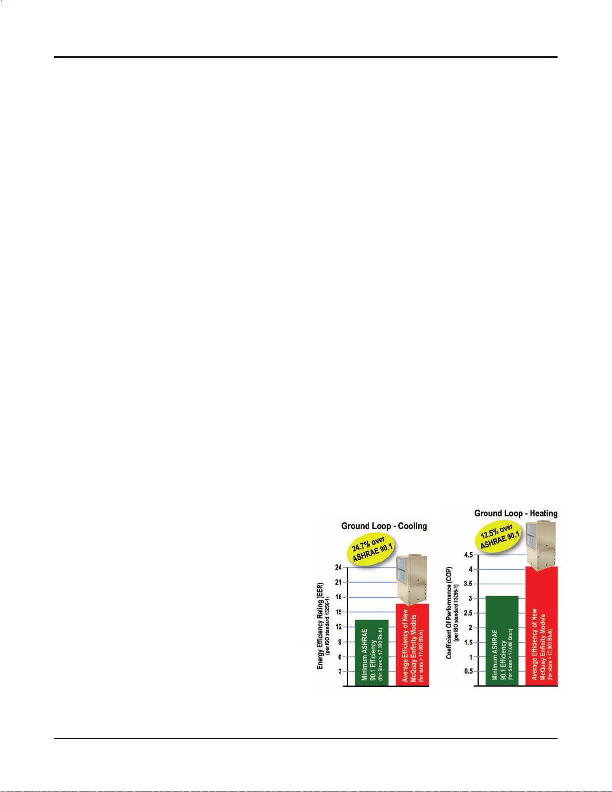
High efciency that minimizes environmental impact
and lowers operating costs
Units exceed ASHRAE Standard 90.1 minimum
requirements
High efciency standard range or geothermal
application exibility
Easy, low-cost design and installation
Two congurations for each unit size (left or right
return) allow you to specify units to t space require
ments and to design the system using minimum ductwork and piping.
Four cabinet sizes, each with McQuay’s small footprint
design, make it easy to meet the space requirements of
your new construction or replacement application.
Flush FPT water ttings allow easy, one-wrench tight-
ening of hose kits and help reduce delays caused by
shipping damage.
Open Choices™ controls feature allows easy, low cost
integration with a Building control Automation System
of your choice.
Factory-installed lter rack saves time and expense to
eld-install a lter rack.
Factory-installed electric heat, desuperheater and ECM
motor options help you meet more specic application
requirements with minimum design or installation time
and expense.
Easy, low-cost maintenance
Easy access to the unit compressor (2-sides), fan sec-
tion (1-side), motor (1-side) and unit controls (front
access).
A removable orice ring allows the blower and motor
to be removed without removing the blower housing or
disconnecting the unit from the ductwork.
Quiet operation
Large fan wheel allows the fan motor to operate at
lower speed for quieter operation.
Two quiet compressor selections (depending on volt-
age and size variations) including rotary (sizes 007 to
015), and scroll compressors (sizes 019 to 070).
Superior Indoor Air Quality (IAQ)
Double-sloped, polymer drain pan promotes positive
condensate drainage.
Optional closed-cell foam insulation (no glass bers in
air stream).
Optional Hot Gas Reheat Coil provides superior
humidity control.
R-410A refrigerant with zero ozone depletion potential
or phase-out date
R-410A is classied as A1/A1 – lower toxicity, no
ame propagation – per ASHRAE Standard 31.
Exceeds ASHRAE 90.1 Minimum Efciencies
4 McQuay Ennity Water Source Heat Pumps Catalog 1103-2
Page 5
Vertical Floor-mounted Features & Options
I/O Expansion
Module
LED Annunciator
MicroTech III Unit
Controller
L
Communication
Module
BACnet
Communication
Module
onWorks
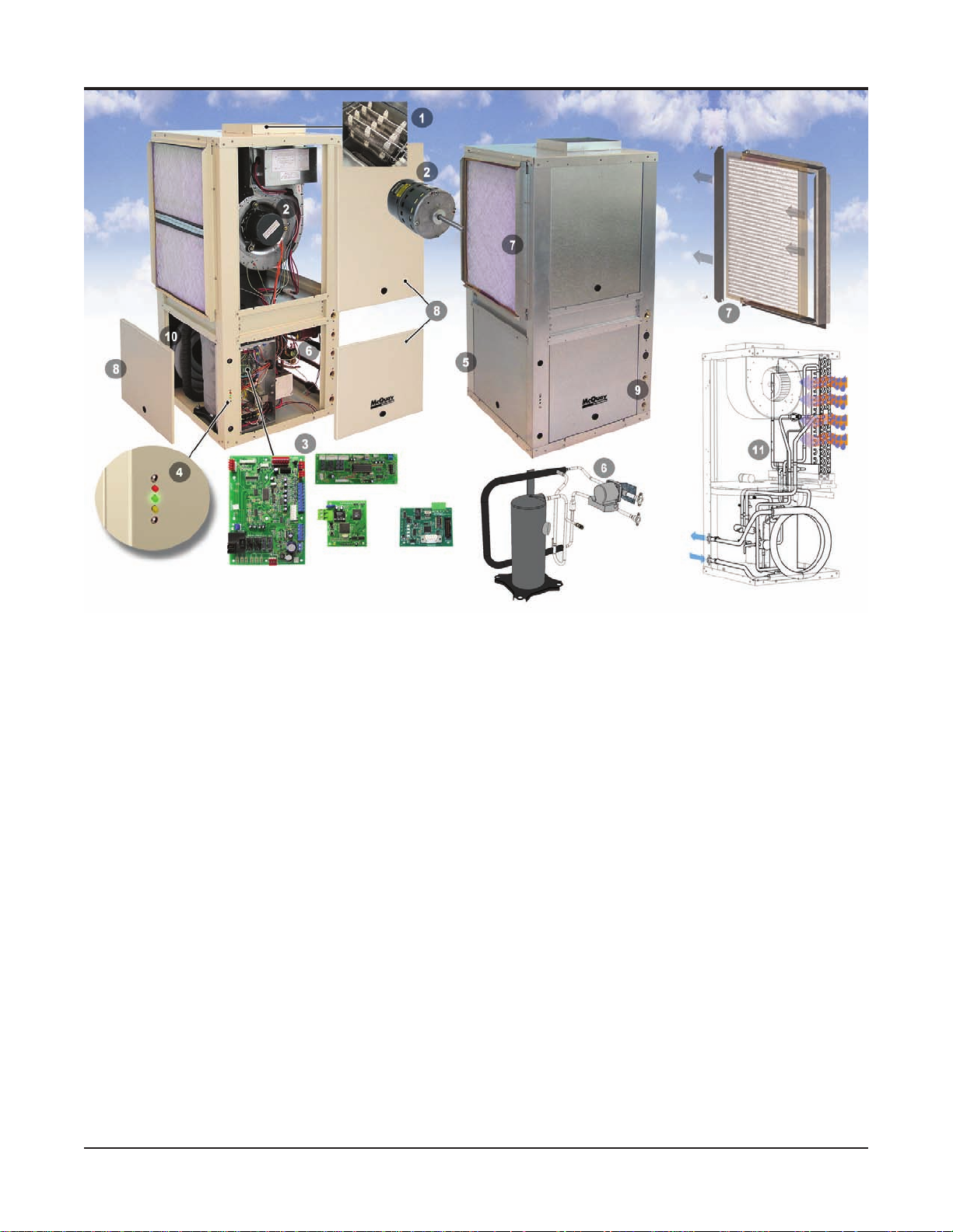
1. Electric Heat (Optional) – Integral electric heat coil provides
supplemental or emergency heat when conditions require.
2. Electronically Commutated Motor (ECM-Optional) - ECM motor
provides quiet, efcient operation while maintaining constant
over its static operating range. Factory programmed for
CFM
3-speeds.
3
. MicroTech® III Unit Controller – Designed for exibility, the
main
control board is used in standalone applications. An
optional I/O expansion module can be used to control electric
heat
and multiple fan speeds. A separate L
net®
communication module can be easily snapped onto the
onWorks® or BAC-
board to accommodate the building automation system of your
choice.
4. LED Annunciator
– External
LED status lights display fault
conditions to provide easy troubleshooting and diagnosis.
5. Compact Cabinet – The
standard unit is constructed of
unpainted G-60 galvanized steel, with the smallest possible
footprint. Optional painted cabinet is ideal for aesthetic requirements
6. Desuperheater (Optional) –
of residential applications.
Saves energy by producing domestic hot water using a small heat exchanger and water pump located
in the compressor compartment. Superheated refrigerant
gas from the compressor, which would otherwise be wasted,
is used to heat water. This reduces the amount of additional
energy required to heat water and it may eliminate the require
for separate water heating equipment.
ment
Desuperheater
Heat Exchanger and
Water Pump Piping Circuit
Optional – Hot Gas Reheat
Piping Circuit
7. Filter & Filter Rack – Units come standard with a 1" (25.4 mm)
thick throwaway lter mounted in a 4-sided combination lter
rack
and return air duct collar. This eliminates the added labor
and cost to eld-mount brackets. Filters can be easily removed
from
any side. A 2" lter rack is available as a factory-installed
selectable option to accept higher efciency lters
8.
Removable Access Panels – Two front panels provide easy
access to the blower motor and unit controls. Two rear panels
provide easy access to the fan housing and compressor section.
9. Piping Connections
– Water connections are FPT water t-
tings, ush with the outside of the cabinet for easy one-wrench
connection
to units. A large condensate connection provides
proper condensate removal.
10. Coaxial Heat Exchanger
– Designed
for maximum heat transfer
at normal and low water ow rates with minimum pressure
drop. The inside tube is deeply uted to enhance heat transfer
and
minimize fouling. A cupro-nickel heat exchanger is avail-
able
as a selectable option.
11. Hot Gas Reheat Coil (Optional) – Provides superior humidity
control by using expelled heat from the refrigeration cycle
and redirecting it through an isolated circuit in the evaporator
section. For every 10°F of temperature rise across the hot gas
reheat coil there is approximately a 20% drop in the discharge
air relative humidity (%Rh). A wall-mounted humidistat is
-
used in conjunction with the unit to measure and adjust the
humidity in the space.
Catalog 1103-2 McQuay Ennity Water Source Heat Pumps 5
Page 6
Vertical Floor-mounted Features and Options
Flexible Congurations
Top View
Right Hand
Return
Air
Control Box
Cabinet
The Ennity Vertical Water Source Heat Pump is
factory assembled and tested for reliability. Five unique
cabinet sizes make up our 1/2 through 6 ton (1.8 through
21.2 kW) vertical heat pump product line. The consistent
shape makes layout simple. Water, condensate and
duct connections are all in similar locations to simplify
installation.
The fan section is separated from the compressor
section with an insulated divider panel for maximum sound
attenuation. A large removable panel provides easy service
access to the blower and motor.
The cabinet is constructed of unpainted, G-60
galvanized steel. The interiors of the top and side panels
and the bottom of the unit are covered with 1/2" thick
(13 mm), 1
standard. An optional closed cell insulation is available for
applications with more stringent IAQ requirements.
1
/2 lb. (681 g) density coated glass ber as
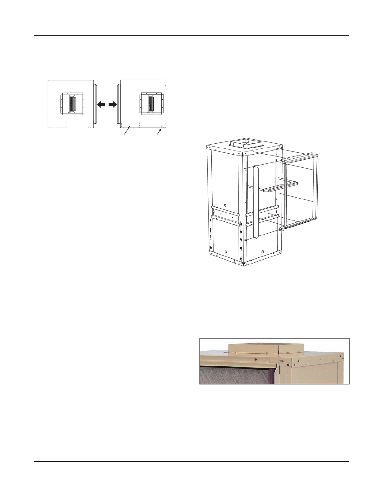
Cabinet Congurations
For maximum exibility, each vertical unit is available
in either a left-hand or right-hand return air arrangement to
provide the optimum piping location and service access.
The mirror image design of the units lets you congure
the system using minimum ductwork and piping. This helps
reduce design, material and installation costs.
Left Hand
Water
Connections
Filter Rack
The lter is supported by factory-mounted brackets that
allow for face removal. Units come standard with a 1" (25.4
mm) thick throwaway lter mounted in a combination lter
rack and return air duct collar, thus eliminating eld mounted
brackets. The lter can be removed from the right or left
side.
Optional factory-mounted or eld-installed 2" lter rack
kit for higher ltration requirements.
Optional 2" Filter Rack
Remove lter from
the left or right
side without a tool
Blower Housing
The blower housing protrudes through the cabinet top
allowing adequate material for connection to a exible
duct.
Fan Housing Protrudes Through the Cabinet Top for
Connection of Flexible Duct
6 McQuay Ennity Water Source Heat Pumps Catalog 1103-2
Page 7
Vertical Floor-mounted Features and Options
Electrical
The electrical components are located in the compressor
section of the unit. Separate holes are provided on the
cabinet to facilitate main power and low voltage control
wiring. All wiring connections are made internal to the
cabinet to reduce the risk of accidental contact. Each
unit is rated to accept time-delay fuses for branch circuit
overcurrent protection. Single phase units are also rated for
use with HACR circuit breakers.
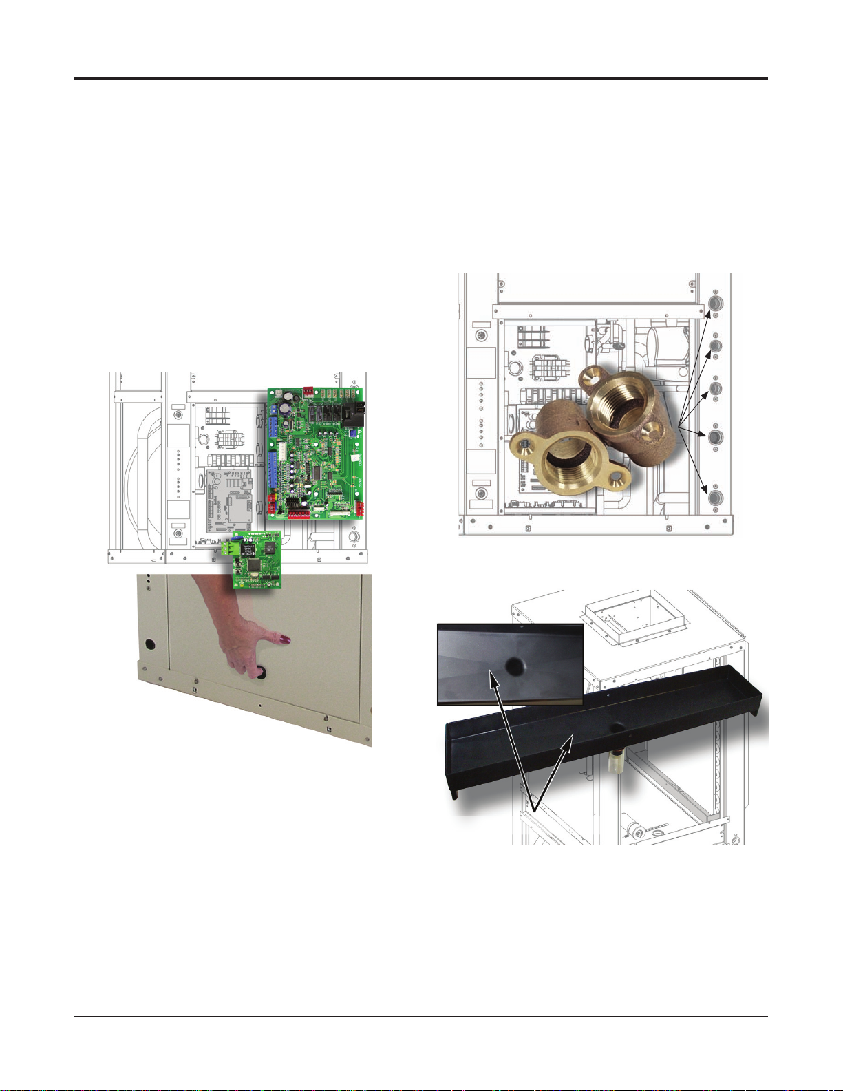
The control box houses the major operating
electrical controls including the MicroTech III unit
controller, transformer, compressor relay and fan relay.
Each component can be accessed easily for service or
replacement.
Easy Access to the Vertical Unit Control Panel
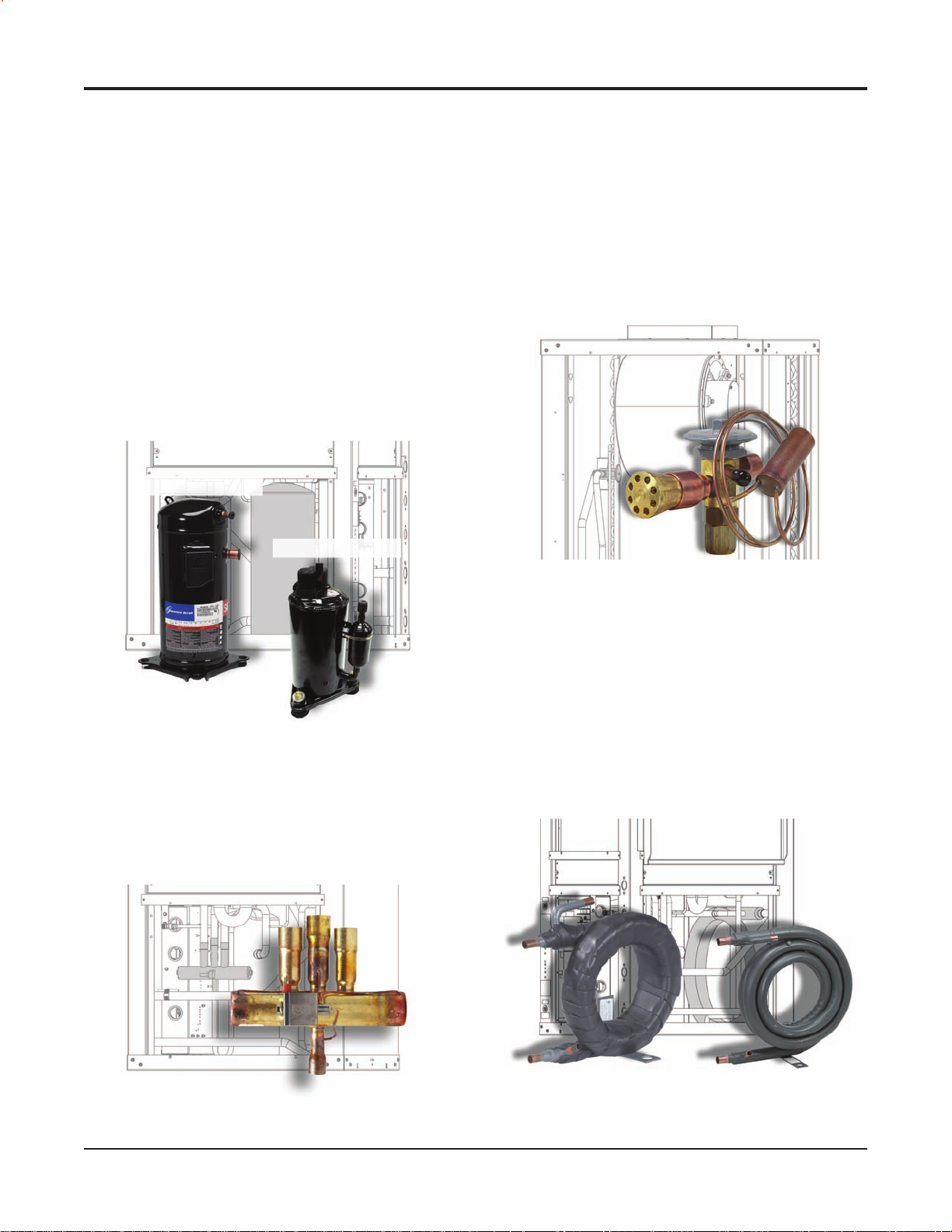
Water Connections
The water and condensate connections are FPT ttings,
securely mounted ush to the corner post to allow for
connection to a exible hose without the use of a back-up
wrench. This helps reduce the time required to connect the
unit and helps prevent delays due to shipping damage. All
vertical units are internally trapped with clear vinyl tubing,
to allow inspection of condensate drain.
Flush FPT Water Fittings
Access panels lift
up and out easily
Vertical Unit Double-Sloped Drain Pan
Double Sloped Channels
Catalog 1103-2 McQuay Ennity Water Source Heat Pumps 7
Page 8
Vertical Floor-mounted Features and Options
R-410A Refrigerant
R-410A refrigerant has zero ozone depletion potential,
no scheduled phase-out and is classied in ASHRAE
Standard 31 as A1/A1 – lower toxicity, no ame
propagation.
Compressors
Ennity water source heat pumps are designed around
the most advanced compressors in the industry. A wide
variety of compressor types are used to offer the best
system design for the dedicated refrigerants and tonnage.
This allows Ennity water source heat pumps to deliver
rated capacity with low noise levels.
Rotary compressor with R-410A is used in vertical units
size 007 to 015. R-410A, non-CFC refrigerant is used in
all unit sizes 007 to 070. Unit sizes 019 to 070 use a scroll
compressor.
Scroll Compressor
Rotary Compressor
Thermal Expansion Valve
All Ennity water source heat pump units include a
thermal expansion valve for refrigerant metering. The
Thermal Expansion Valve (TXV) allows the unit to operate
at optimum efciency with uid temperatures ranging from
30ºF to 110ºF, and entering air temperatures ranging from
40ºF to 90ºF. The TXV precisely meters the exact amount
of refrigerant ow through the system to meet the load and
deliver rated heating and cooling capacity.
Thermal Expansion Valve (TXV)
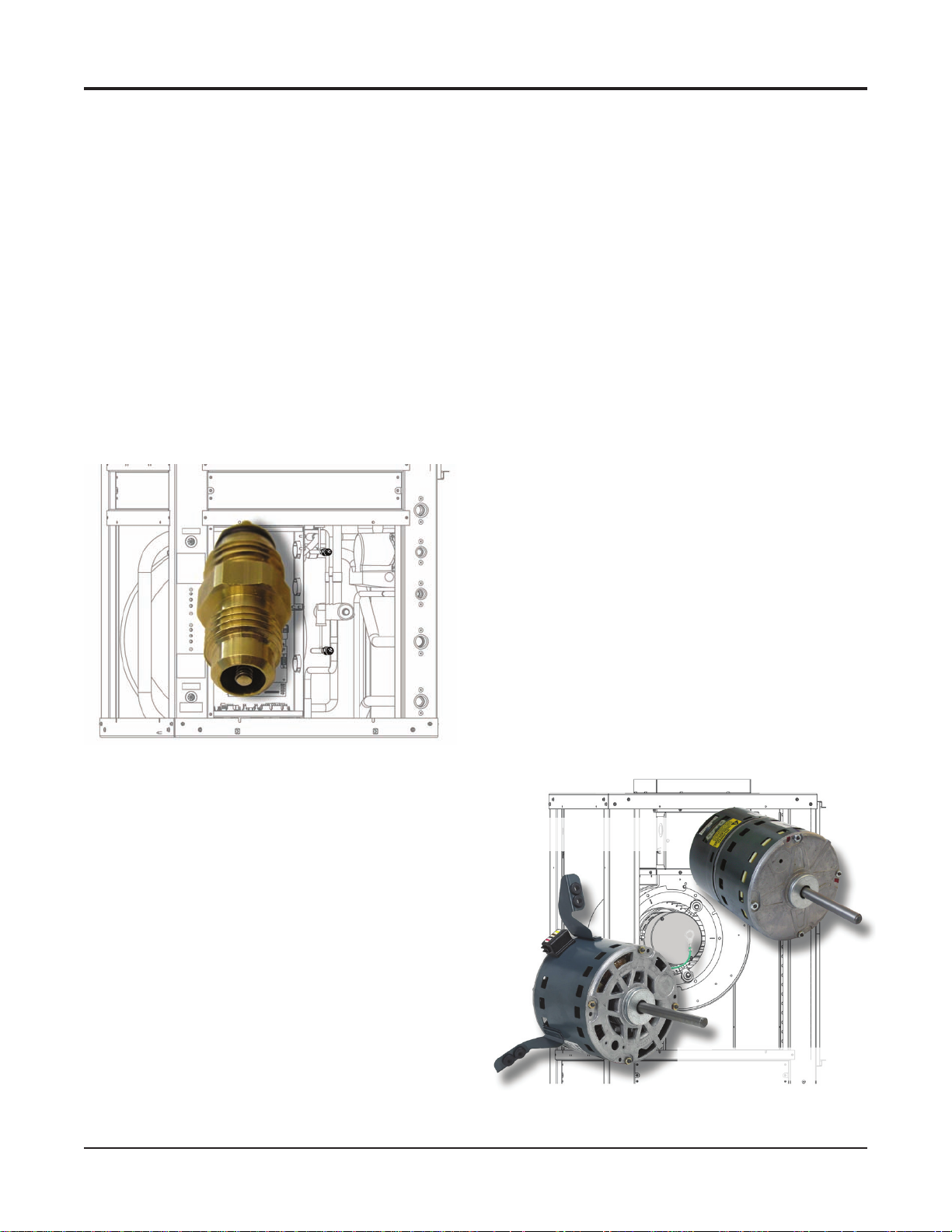
Reversing Valve
A 4-way reversing valve is included with all Ennity water source heat pumps. The valve is energized in
the heating mode and will “fail-safe” to the cooling mode
which is the predominant mode of operation for
commercial applications.
4-Way Reversing Valve
Fluid-to-Refrigerant Coil
The copper or cupronickel (optional) tube-in-tube
coaxial heat exchanger used in Ennity water source heat
pumps are designed for maximum heat transfer at normal
and low water ow rates with minimum pressure drop. The
inside tube is deeply uted to enhance heat transfer and
minimize fouling. All coaxial coils are tested to 400 psig on
the water side and 500 psig on the refrigerant side.
Geothermal range (VFW) units include coil and piping insulation to protect against condensation in low-temperature
geothermal applications.
Coaxial Heat Exchanger
8 McQuay Ennity Water Source Heat Pumps Catalog 1103-2
Page 9
Vertical Floor-mounted Features and Options
Noise Reduction
Ennity Water Source Heat Pumps include multiple
features and options to reduce unwanted noise generation
including scroll and rotary compression, viscoelastic acoustical mass plate, vibration isolated fan mounts, optional
compressor sound blankets and soft starting ECM motors.
While good design and installation practices are always
required to prevent objectionable noise, McQuay, as a
leader in engineered products can also provide many other
customized solutions to meet your applications
requirements.
Schrader Connections
Two Schrader valves are located inside the end access
panel – one on the low side and one on the high side of the
refrigeration circuit – for charging and servicing. All valves
are 7/16" SAE ttings.
Schrader Valve
to lock out compressor operation at extreme conditions.
For additional protection, unit sizes 015 and larger have a
7 psi (48 kPa) low-pressure switch to protect the compressor from low refrigerant charge. The low setting prevents
nuisance trips while providing additional protection.
Blower Section
The blower section includes the blower housing, wheel,
motor and drain pan. It is separated from the compressor
section by an insulated divider panel for maximum sound
attenuation. The large size of the blower wheel allows it
to rotate more slowly, reducing motor work to improve
efciency and provide for quiet operation. A large panel
provides service access to the blower and motor. All
blower/motor assemblies have a removable orice ring on
the housing to accommodate motor and blower removal
without disconnecting the unit from the ductwork.
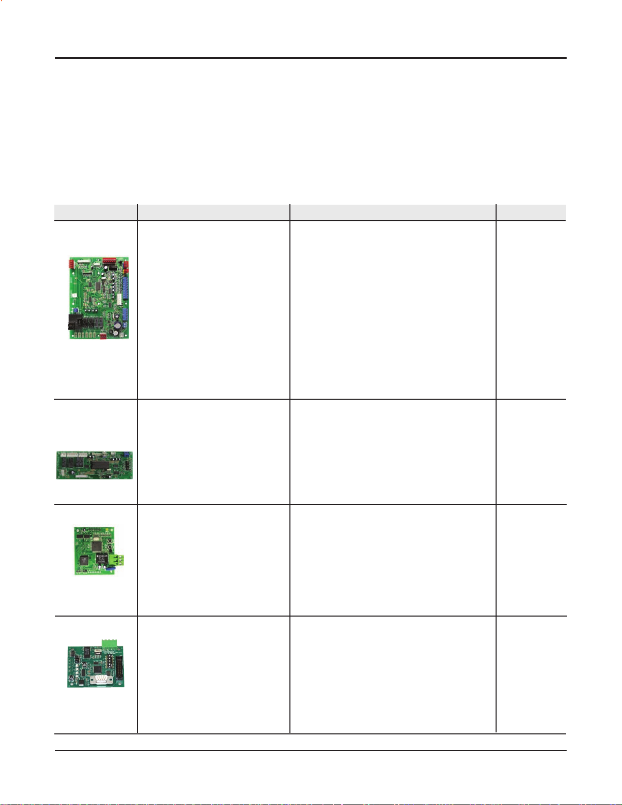
Blower Motors
The standard blower motor is a multi-speed, Permanent
Split Capacitor (PSC) type with thermal overload protection. It is permanently lubricated. The motor is factory
wired to maximize performance and efciency. Unit sizes
019 and larger have a terminal strip on the motor for simple
motor speed change without going back to the control
box. The motor is isolated from the fan housing using
rubber isolators to minimize vibration transmission. All
blower/motor assemblies have a removable orice ring on
the housing to accommodate motor and blower removal
without disconnecting the unit from the ductwork. Optional
Electronically Commutated Motor (ECM) provides soft
start, maintains consistent CFM over its static operating
range and fan speed can be adjusted automatically based on
mode of operation.
High Efciency Blower Motor Options
Air-to-Refrigerant Coil
The air-to-refrigerant heat exchanger is a large face
area coil with copper tubes and aluminum ns. The ns are
lanced and mechanically bonded to the tubes using nned
edges on the inside which expand during assembly to
enhance heat transfer capabilities. The maximum working
pressure of the heat exchanger is 500 psig (3447 kPa). The
coil is designed for optimal performance in both heating
and cooling while maintaining the benet of a compact
size. Coils can be provided with an optional E-coating.
Electronically Commutated
Motor (ECM)
Refrigeration System
Units have a coaxial heat exchanger with a copper inner
tube and a steel outer tube. The air coil is a large face area
coil with copper tubes and aluminum ns. Safety controls
include a high-pressure switch and low-temperature sensor
Catalog 1103-2 McQuay Ennity Water Source Heat Pumps 9
Permanent Split Capacitor
Motor (PSC)
Page 10
Control Options – Control Choices and Added Functionality
The control box is accessible through the left or right end
corner panel. It houses the major operating electrical controls
including the MicroTech® III unit controller, transformer,
compressor relay and fan relay. Each component is easily
accessed for service or replacement.
Four unique control choices are offered with the MicroTech III unit controller:
■ Standalone operation using a MicroTech III unit controller
■ MicroTech III unit controller with I/O Expansion module
■ MicroTech III unit controller with a Lonworks® commu-
nication module
■ MicroTech III unit controller with a BACnet® communication module
Each option features direct quick-connect wiring to all
unit-controlled components for “clean” wiring inside the
control box. Each control circuit board receives power from
a 50 VA transformer.
Control Description Application Protocol
Uni t-mounte d
or wall-mounted
thermostat
MicroTech III
(Standalone)
Unit Controller
The MicroTech III unit controller is
a standalone microprocessor-based
control board conveniently located
in the unit control box for accessibil
. The board is designed to provide
ity
standalone control of a Water Source
Heat Pump using a wall thermostat
or a wall mounted temperature sen
or. Each unit controller is factory
s
programmed, wired, and tested. For
added functionality an optional I/O
expansion
MicroTech III controller for complete
control and operation of your McQuay
water source heat pump.
module interconnects to the
Each unit controller is factory programmed, wired,
and tested for complete control of single zone, standalone
operation of your McQuay Water Source Heat
Pump.
-
-
I/O Expansion
Module
LonWorks
Communication
Module
BACnet
Communication
Module
The I/O Expansion Module is an extens
ion of the Microtech III unit controller
and provides additional functionality to
the Microtech III control system. The
interconnect cable from the I/O expan-
module to the MicroTech III unit
sion
controller provides two-stage operation
of the water source heat pump.
The MicroTech III unit controller can
accept a plug-in LonWorks communication module to provide network
communications and added functional
ity
to easily integrate with an existing
BAS. The communication module can
be factory- or field-installed and is
tested with all logic required to monitor
and control the unit.
The MicroTech III unit controller
can accept a plug-in BACnet communication module to provide network
communications and added functionality to easily integrate with an existing
BAS. The communication module can
be factory- or field-installed and is
tested with all logic required to monitor
and control the unit.
Allows
for:
• Monitoring of entering water temperature for
boilerless electric heat control.
• Outputs for optional electric heat
• Output for multi-speed fans on a standard water
source heat pump.
• Independent LED annunciator to easily identify
operation fault conditions for two-stage units.
LonTalk application protocol is designed for units
that are integrated into a LonWorks communication
network for centralized scheduling and management
of multiple heat pumps.
-
Designed to be linked with a centralized building
automation system (BAS) through a BACnet com
munications
management of multiple heat pumps.
network for centralized scheduling and
Uni t-mounte d
or wall-mounted
thermostat
onMark 3.4
L
BaCnet
-
10 McQuay Ennity Water Source Heat Pumps Catalog 1103-2
Page 11
Control Features – MicroTech® III Control System
The MicroTech III Unit Controller is a microprocessorbased control board conveniently located in the unit control
box for easy access through a removable access panel. The
standalone unit controller is a hard wired interface and pro-
vides all the necessary eld connections. The board can be
wired for 24-volt AC output to the wall thermostat by using
terminals R & C. An LED annunciator is located on the front
corner of the unit chassis to quickly check the operating status
of the unit.
MicroTech III Operating Features
Assumes cycle fan operation-not continuous fan operation:
■ Start-up – The unit will not operate until all the inputs
and safety controls are checked for normal conditions.
■ Cooling mode – On a call for cooling, the compressor
and fan will start 0 to 30 seconds later. When the load is
satised, the compressor and fan shut off.
■ Heating Mode – On a call for heating, the reversing valve
is energized after 60 seconds and the compressor and fan
start. When the load is satised, the compressor and fan
shut off. The reversing valve is de-energized 60 seconds
later.
■ Short Cycle Protection & Random Start – Each time
the compressor stops, a new random compressor start-
delay time between 180 and 240 seconds is generated.
This prevents compressor short cycling and prevents units
from starting simultaneously after coming back from an
unoccupied cycle.
■ Unoccupied Mode – A simple “grounded” signal between
terminals U and C (no power source required), puts the
unit into the unoccupied mode for night setback operation.
■ Override Mode – A switch on the deluxe automatic
changeover thermostat can be activated during the unoccupied mode to put the unit back into the occupied mode
for two hours for after-hours heating or cooling.
■ Motorized Valve/Pump Restart – The IV/PR (H8) ter-
minals on the The MicroTech III unit controller are used
to energize (open) a motorized valve or start a water pump
to get water circulating prior to starting the compressor
on call for heating or cooling. The IV/PR (H8) terminal
may
be “daisy chained” between 200 units.
■ Brownout Protection – The MicroTech III unit controller
measures the input voltage and will suspend compressor
and fan operation if the voltage falls below 80% of the
unit nameplate rated value. A unique LED status is generated and an output is available to a “fault” LED at the
thermostat.
Unit Shutdown – A simple grounded signal puts the unit
■
into the shutdown mode. Compressor and fan operations
are suspended. A unique LED status is generated and an
output signal is made available for connection to a “fault”
LED at the thermostat.
■ Condensate Overow Protection – The
MicroTech III
unit controller incorporates a liquid sensor at the top of the
drain pan. Upon sensing water ow, cooling operation is
suspended. A unique LED status is generated and output
is available to a “fault” LED at the thermostat. Heating
operation is not suspended.
■ Remote Reset of Automatic Lockouts – The Remote Re-
set feature provides the means to remotely reset automatic
lockouts generated by high-pressure and/or low-temperature faults. When the MicroTech III unit controller is in
automatic lockout due to one of these faults, and the cause
of the fault condition has been alleviated, energizing the
O-terminal for 10 seconds or more will force the control
board to clear the lockout. A unit power cycle can also
be used to clear an automatic lockout if the conditions
causing the fault have been alleviated.
■ Intelligent Reset – The Fault Retry feature helps to
minimize nuisance trips of automatic lockouts caused by
high-pressure and/or low-temperature faults. This feature
clears faults the rst two times they occur within a 24-hour
period and triggers an automatic lockout on the 3rd fault.
The retry count is reset to zero every 24 hours.
■ Equipment Protection Control – The MicroTech III
unit controller receives separate input signals from the
refrigerant high-pressure switch and the low suction line
temperature sensor. In a high-pressure situation, compressor operation is suspended. In a low temperature situation,
the unit goes into a defrost cycle where the unit is put into
cooling operation for 60 seconds until the coaxial heat
exchanger is free of ice. Each switch generates its own
unique LED status and output is available to a “fault”
LED at the thermostat if either situation exists.
Note: Most unit fault conditions are the result of operating
the equipment outside the unit specications.
MicroTech III unit controller LED & fault outputs
Mode / Fault
Occupied, Bypass,
Standby
Override
Unoccupied On On Off Energized
Condensate Overow On Off Off De-energized
High Pressure 1 Fault
Low Pressure 1 Fault Off Off On De-energized
Low Temperature 1 Fault Flash Off Off De-energized
Brownout
Emergency Shutdown
Room/Return
Temp Sensor 1 Failure
Service Test Mode
Enabled
Serial EEPROM
Corrupted
Network “Ofine”
Received
1
Compressor relay/compressor terminal is labeled COMP, switched line of
the same electric input as any of the L1 terminals.
Status LED’
, or Tenant Off On Off Energized
Air or Low
1
ellow Green Red Output-Terminal “A”
Y
Off Off Flash De-energized
Off Flash Off De-energized
Off Flash Off De-energized
Flash Flash On De-energized
On On Off De-energized
On On On De-energized
Off Off Off De-energized
s
Thermostat Alarm Light
Catalog 1103-2 McQuay Ennity Water Source Heat Pumps 11
Page 12
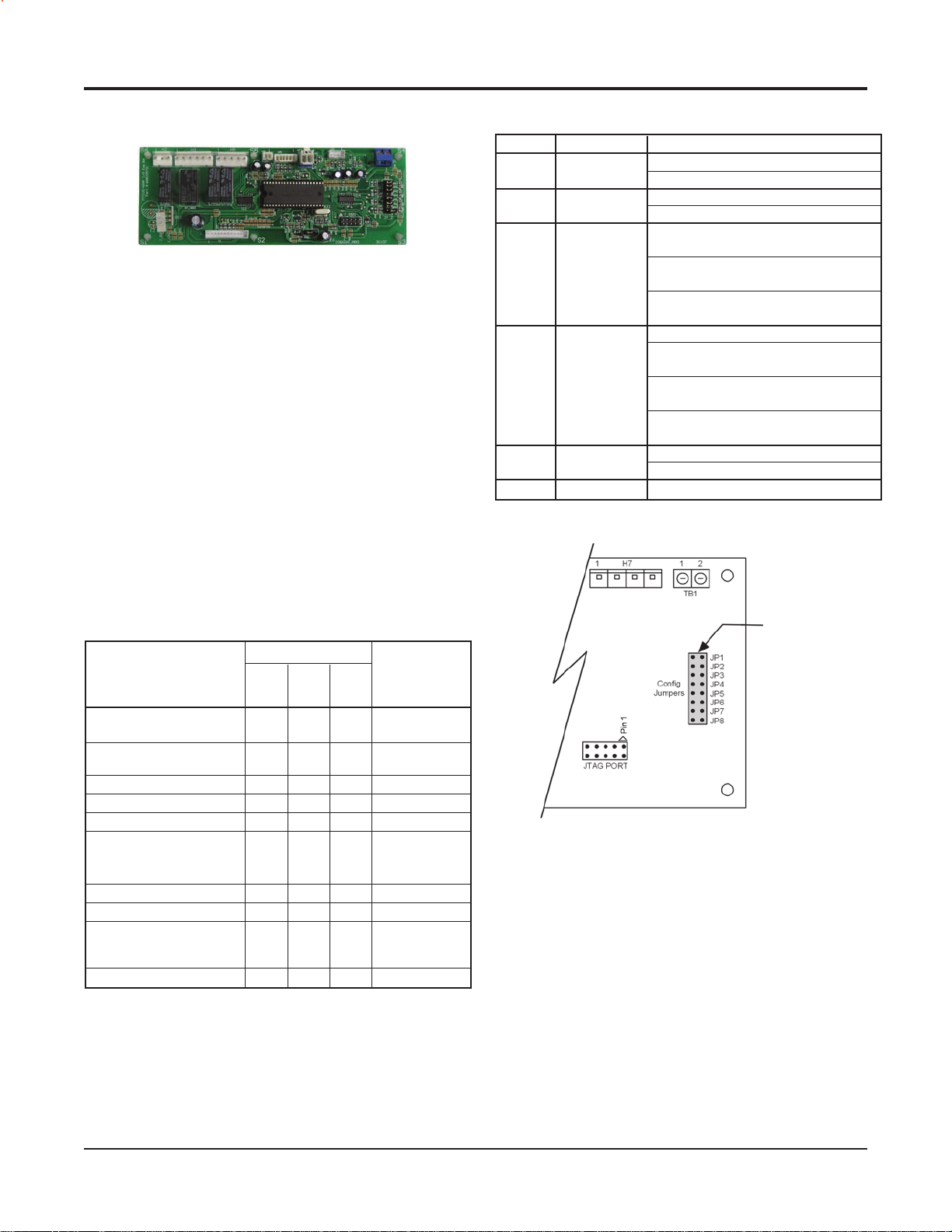
Control Features – I/O Expansion Module
I/O Expansion Module
The I/O Expansion Module is a factory installed option.
It is an extension of the MicroTech III unit controller and
provides extra functionality.
The I/O Expansion Module has 4 main purposes:
The Microtech III unit controller in combination with
the I/O Expansion Module will be the standard control
system for dual-circuit Water Source Heat Pump
equipment. For example: large vertical units.
The I/O Expansion Module has outputs to control
electric heat on a standard Water Source Heat Pump.
The I/O Expansion Module has outputs for multi-speed
fans on a standard Water Source Heat Pump.
The I/O Expansion Module has an independent LED
annunciator to identify operational fault conditions on
dual-circuit equipment.
I/O Expansion Module Conguration Jumper Settings
Jumper Description Options
JP1 Number of
JP2
Water Reheat Shorted to enable reheat
JP3 and JP4 open for no
supplemental heat
JP3 Supplemental JP3 open, JP4 shorted for
& JP4 Heat Type boilerless electric heat
JP3 and JP4 shorted is an
invalid setting
JP5 and JP6 open for single-speed fan
JP5
& JP6 Selection JP5 shorted and JP6 open for
two-speed fan
JP 5 and JP6 shorted is an
invalid setting
JP7
Speed Type Shorted for two-speed compressor
JP8 Future Spare
Compressors Shorted for dual compressor
Hot Gas/
Fan Speed three-speed fan
JP5 open, JP6 shorted for
Compressor Open for single-speed compressor
Open for single compressor
Open to disable reheat
I/O Expansion Module Conguration Jumper Terminals
I/O Expansion Module LED & Fault Outputs
Invalid Conguration
Jumper Setting
Base Board
Communication Fail
High Pressure #2 Fault Off Off Flash De-energized
Low Pressure #2 Fault Off Off On De-energized
Unoccupied Mode On On Off Energized
Occupied, Bypass,
Standby, or Tenant
Override Modes
Mode / Fault
Low Suction Temp #2 Fault Flash Off Off De-energized
Sensor Failures Low Suction
Low Suction
1
EWT (w/ Boilerless EH only)
2
Service Test Mode Enabled Flash Flash Flash De-energized
Normal Operation
Y
Temp #2, Flash Flash On De-energized
Off On Off De-energized
Status LED's
ellow Green Red
Flash Flash Off De-energized
Off Flash Flash N/A
Off On Off Energized
Terminal “A”
Thermostat Alarm
Light Output
Note: Mode / Faults are listed in order of priority.
1
Boilerless electric heat only
2
Alarm/fault LED indications take precedence over service test mode LED
indication. The controller shall use service test mode if the service test mode
jumper is installed, even if the LED’s indicate an alarm/fault.
Jumper Terminals
Features
Standard Heat Pumps / Single Circuit Units
Monitors entering water temperature for boilerless
electric heat control
Outputs for medium and high speed fan controls.
Second Circuit Units
High pressure switch
Low pressure switch
Low suction line temperature sensor
Compressor output
Reversing valve
12 McQuay Ennity Water Source Heat Pumps Catalog 1103-2
Page 13
Control Features – MicroTech III Controller with LonWorks Module
MicroTech III / unit control board LED & fault outputs
Mode / Fault
Occupied, Bypass,
Standby
Override
Unoccupied On On Off Energized
Condensate Overow On Off Off De-engergized
High Pressure 1 Fault
Low Pressure 1 Fault Off Off On De-energized
Low Temperature 1 Fault Flash Off Off De-energized
Brownout
Emergency Shutdown
Room/Return
Temp Sensor 1 Failure
Service Test Mode
Enabled
Serial EEPROM
Corrupted
Network “Ofine”
Received
1
Compressor relay/compressor terminal is labeled COMP, switched line of
the same electric input as any of the L1 terminals.
Status LED’
, or Tenant Off On Off Energized
Air or Low
1
ellow Green Red Output-Terminal “A”
Y
Off Off Flash De-energized
Off Flash Off De-energized
Off Flash Off De-energized
Flash Flash On De-engergized
On On Off De-energized
On On On De-energized
Off Off Off De-enegized
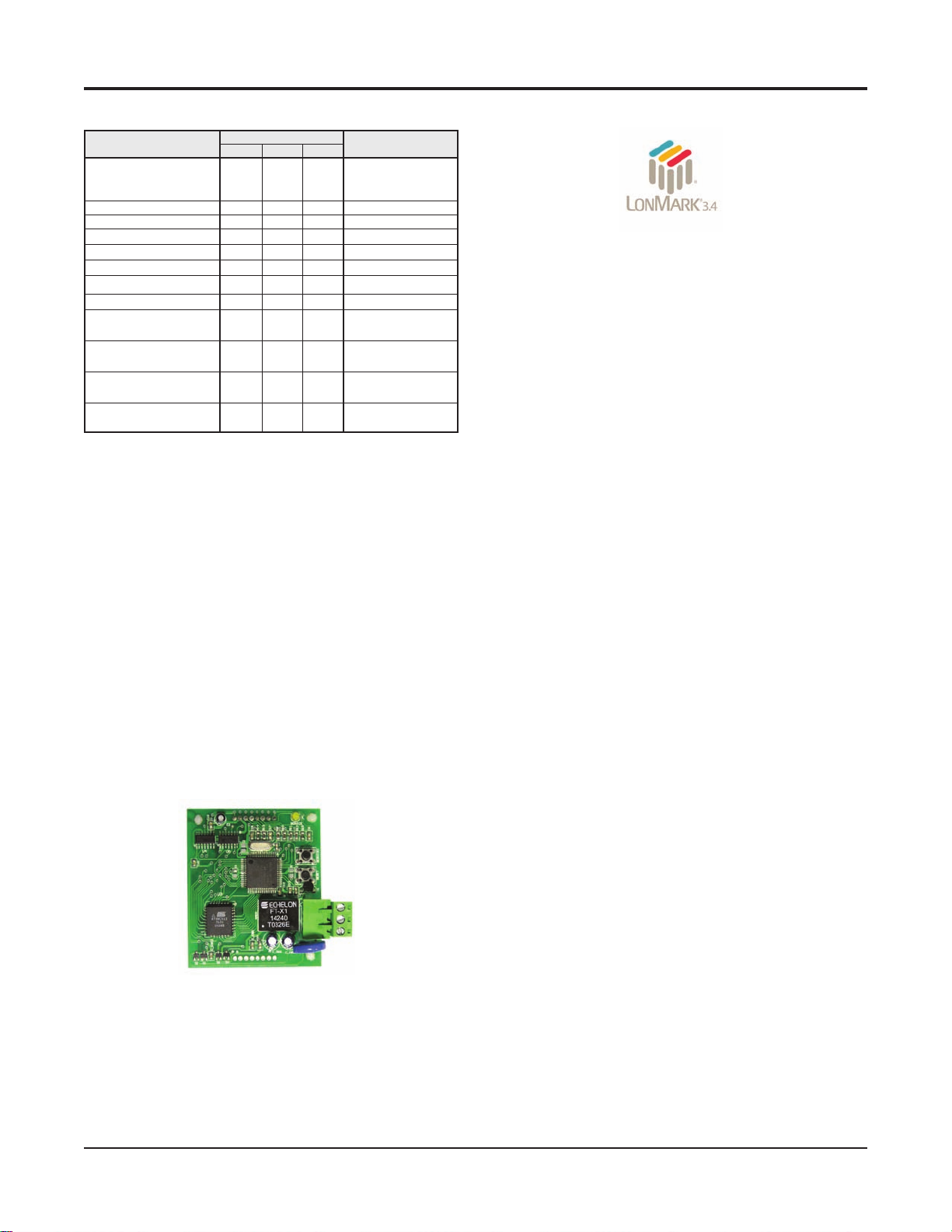
MicroTech III Unit Controller with LonWorks®
Communication Module
Each McQuay water source heat pump can be equipped
with a LonWorks communication module that is LonMark
3.4 certied. The controller is microprocessor-based and is
designed to communicate over a LonWorks communica-
tions network. It can be factory or eld-installed.
The unit controller is programmed and tested with
all the logic required to monitor and control the unit. An
optional wall sensor may be used with the communication module to provide limited local control of the Water
Source Heat Pump. The unit controller monitors water and
air temperatures and passes information to the communication module. The module communicates with the BAS, to
provide network control of the Water Source Heat Pump.
s
Thermostat Alarm Light
MicroTech III Unit Controller with LonWorks
Communication Module orchestrates the following unit
operations:
Enable heating and cooling to maintain setpoint
based on a room sensor
Enable fan and compressor operation
Monitors all equipment protection controls
Monitors room and discharge air temperatures
Monitors leaving water temperature
Relays status of all vital unit functions
The MicroTech III unit controller with communication
module includes:
A unit-mounted return air sensor*
A unit-mounted discharge air sensor*
A leaving water temperature sensor
* Discharge air and return air sensors must be
eld-installed per IM 956.
communication module provides access to
The
setpoints for operational control
Available wall sensors include:
Room sensor with LED status and tenant override
button
Room
sensor with LED status, tenant override
button, and ±3°F setpoint adjustment
Room
sensor with LED status, tenant override
button, 55° to 90°F setpoint adjustment
The MicroTech III unit controller with communication module includes a unit-mounted return air, discharge
air and leaving water temperature sensor. Wall mounted
temperature sensors include setpoint adjustment and tenant
override. The user has the capability of substituting the wall
sensor with a duct-mounted return air sensor.
Catalog 1103-2 McQuay Ennity Water Source Heat Pumps 13
Page 14
Control Features – MicroTech III Controller with BACnet Module
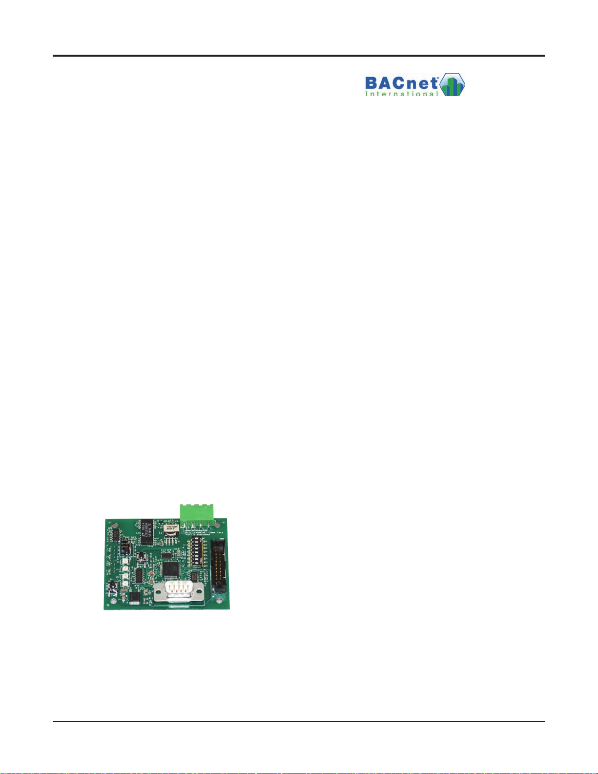
MicroTech III Controller with BACnet
Communication Module
McQuay water source heat pumps are available with
McQuay BACnet MS/TP communication module that
is designed to communicate over a BACnet MS/TP
communications network to a building automation system
(BAS). It can be factory or eld-installed.
The unit controller is programmed and tested with all the
logic required to monitor and control the unit. An optional
wall sensor may be used with the communication module to
provide limited local control of the water source heat pump.
The unit controller monitors water and air temperatures
and passes information to the communication module. The
module communicates with the BAS, to provide network
control of the water source heat pump.
The module makes operational data and commands
available on a communications network using BACnet
objects and properties:
The network cable is a shielded twisted-pair cable
Network communications run up to 76.8 Kbps
DIP switches on the controller enable the MS/TP MAC
address to be set in the range 0-127
Four green status LEDs on the communication module
indicate communication activity on the MS/TP communication network and with the unit controller
MicroTech III Unit Controller with BACnet MS/TP
Communication Module orchestrates the following
unit operations:
Enable heating and cooling to maintain setpoint
based on a room sensor
Enable fan and compressor operation
Monitors all equipment protection controls
Monitors room and discharge air temperatures
Monitors leaving water temperature
Relays status of all vital unit functions
The MicroTech III unit controller with communication
module includes:
A unit-mounted return air sensor*
A unit-mounted discharge air sensor*
A leaving water temperature sensor
* Discharge air and return air sensors must be
eld-installed per IM 956.
communication module provides access to
The
setpoints for operational control
Available wall sensors include:
Figure 13. MicroTech III BACnet Water Source Heat Pump
Snap-in Communication Module
Room sensor with LED status and tenant override
button
Room
sensor with LED status, tenant override
button, and ±3°F setpoint adjustment
Room
sensor with LED status, tenant override
button, 55° to 90°F setpoint adjustment
14 McQuay Ennity Water Source Heat Pumps Catalog 1103-2
Page 15
Applications – Systems
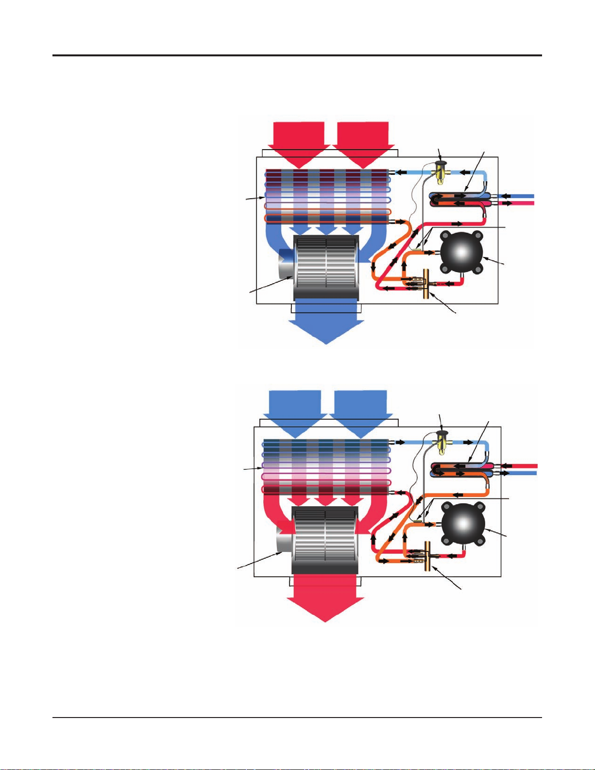
Typical Cooling and Heating Refrigeration Cycles
Note: For standard heat pump operation only
Cooling Refrigeration Cycle
When the wall thermostat calls
for COOLING, the reversing valve
directs the ow of the refrigerant, a
hot gas, from the compressor to the
water-to-refrigerant heat exchanger.
There, the heat is removed by the
water, and the hot gas condenses
to become a liquid. The liquid then
ows through a thermal expansion
valve to the air-to-refrigerant heat
exchanger coil. The liquid then
evaporates and becomes a gas, at the
same time absorbing heat and cooling
the air passing over the surfaces of
the coil. The refrigerant then ows as
a low pressure gas through the reversing valve and back to the suction side
of the compressor to complete the
cycle.
Heating Refrigeration Cycle
When the wall thermostat calls
for HEATING, the reversing valve
directs the ow of the refrigerant, a
hot gas, from the compressor to the
air-to-refrigerant heat exchanger coil.
There, the heat is removed by the
air passing over the surfaces of the
coil and the hot gas condenses and
becomes a liquid. The liquid then
ows through a thermal expansion
valve to the water-to-refrigerant heat
exchanger. The liquid then evaporates
and becomes a gas, at the same time
absorbing heat and cooling the water.
The refrigerant then ows as a low
pressure
valve and back to the suction side of
the compressor to complete the cycle.
gas through the reversing
Air to
Refrigerant
Heat
Exchanger
Coil
Blower
Air to
Refrigerant
Heat
Exchanger
Coil
Blower
Return Air
Conditioned Air
(Cooling)
Return Air
Conditioned Air
(Heating)
Thermal
Expansion Valve
Reversing Valve
Thermal
Expansion Valve
Reversing Valve
Water to Refrigerant
Heat Exchanger
Water In
Water Out
Sensing
Bulb and
Capillary
Tube
Compressor
Water to Refrigerant
Heat Exchanger
Water In
Water Out
Sensing
Bulb and
Capillary
Tube
Compressor
Catalog 1103-2 McQuay Ennity Water Source Heat Pumps 15
Page 16
Applications – Systems
Water source heat pump systems are one of the most ef-
cient, environmentally friendly systems available for heating
and cooling buildings. High-efciency, self contained units
(sizes 7,000 btuh to 420,000 btuh) can be placed in virtually
any location within a building. Each unit responds only to
the heating or cooling load of the individual zone it serves.
This permits an excellent comfort level for occupants, better
control of energy use for building owners and lower seasonal
operating costs. The Air-Conditioning Refrigeration Institute
(ARI) and the International Standards Organization (ISO)
publish standards so that water source heat pumps are rated
for specic applications. The ARI/ISO loop options shown in
this catalog are typical water source heat pump loop choices
available in today’s market. These systems offer benets rang-
ing from low cost installation to the highest energy efciency
available in the market today.
Boiler / Tower Applications: ARI 320 / ISO
13256-1
A “Boiler/Tower” application uses a simple two-pipe
water circulating system that adds heat, removes heat or
transfers rejected heat to other units throughout the building. The water temperature for heating is generally maintained between 65ºF – 70ºF and is usually provided by a
natural gas or electric boiler located in a mechanical room.
The condensing water temperature, during cooling months,
is maintained between 85ºF and 95ºF and requires the use
of a cooling tower to dissipate waste heat. Cooling towers can be located on the roof, or inside or adjacent to the
building. This application can be the lowest cost of the loop
options available.
Note: ASHRAE 90.1 standards require that circulating
pumps over 10 HP will require use of “variable frequency
drive” equipment and pipe insulation to be used whenever
water temperatures are below 60 degrees and above 105
degrees. See ASHRAE 90.1 Standards for details.
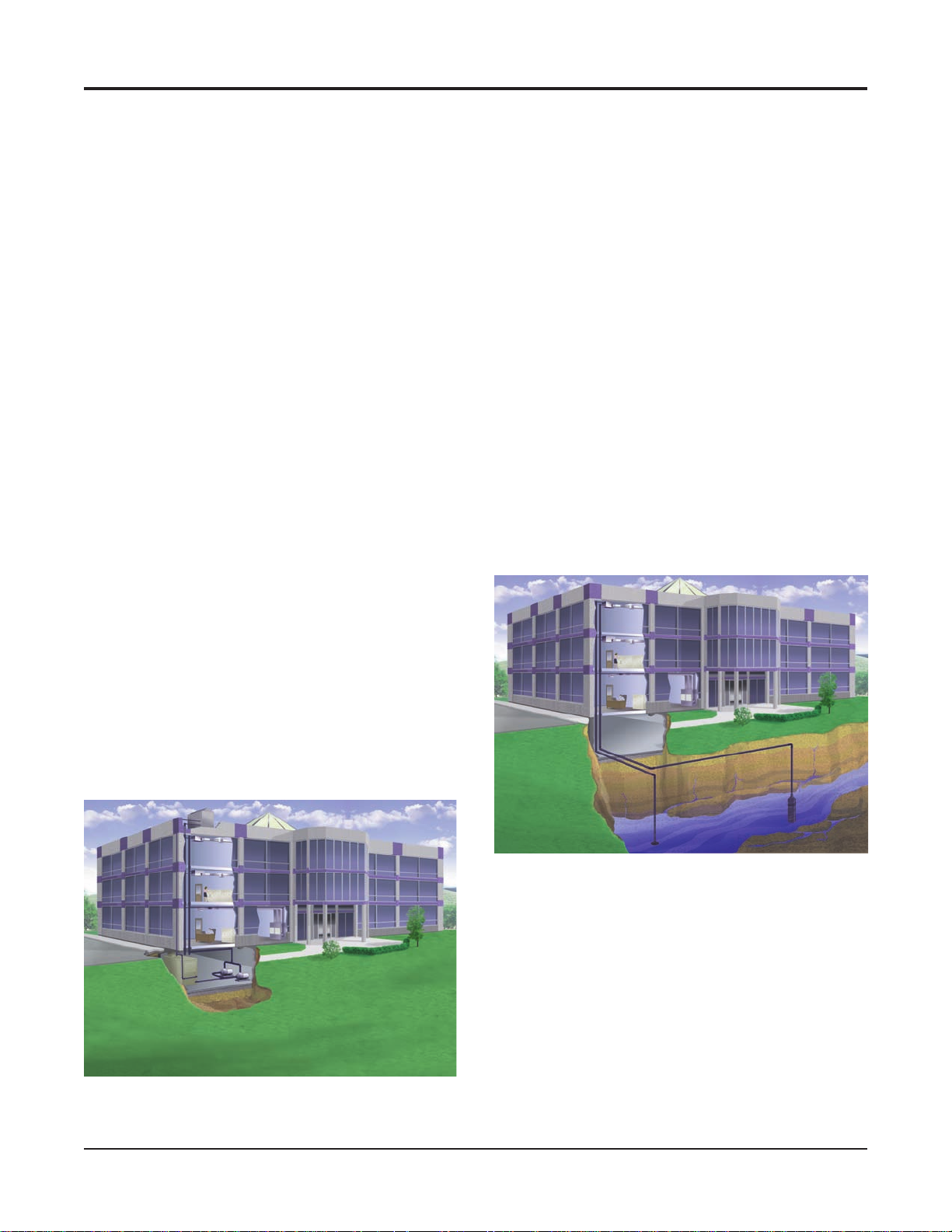
Open Loop Well Water Applications: ARI
325 / ISO 13256-1
“Open Loop” well water systems use ground water
to remove or add heat to the interior water loop. The
key benet of an open loop system is the constant water
temperature, usually 50ºF to 60ºF, which provides efcient
operation at a low rst cost. Most commercial designers
incorporate a heat exchanger to isolate the building loop
from the well water. Using heat exchangers can reduce
maintenance issues while still allowing the transfer of heat
from unit to unit as with the “Boiler/Tower System”. A successful design provides an ample amount of groundwater
(approximately 2 GPM per ton) and adequate provisions
for discharging water back to the aquifer or surface. Open
Loop applications are commonly used in coastal areas
where soil characteristics allow reinjection wells to return
the water back to the aquifer. Note that some states have requirements on the depths of return water reinjection wells,
and such wells must be approved by the United States Environmental Protection Agency. Also, bad water quality can
increase problems with heat exchanger scaling. Suspended
solids can erode the heat exchanger. Strainers can be used
to contain suspended solids.
Open Loop Well Application
Boiler/Tower Application
16 McQuay Ennity Water Source Heat Pumps Catalog 1103-2
Page 17
Applications – Systems
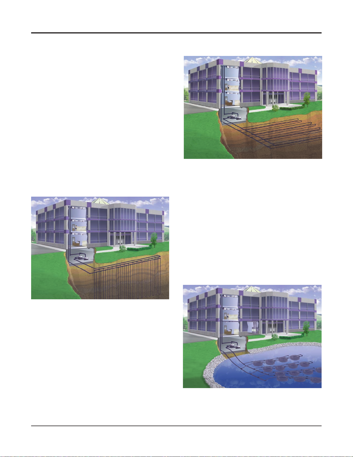
Closed Loop Geothermal Applications ARI
330/ISO 13256-1
“Vertical Closed Loop” applications are installed by
drilling vertical bore holes into the earth and inserting
a plastic polyethylene supply/return pipe into the holes.
The vertical wells are connected in parallel reverse return
fashion to allow the water from the building to circulate
evenly throughout the boreeld. The circulating uid dissipates heat to the ground in a similar manner as a “tower”
and adds heat back to the loop like a boiler. If properly
designed, the loop eld can maintain the loop temperatures
necessary to condition the building without the use of a
boiler or a tower. Loop temperatures usually range from
37ºF to 95ºF in Northern climates. Southern applications
can see temperatures ranging from 40ºF to 100ºF. The
number of bore holes and their depth should be determined
by using commercial software that is specically designed
for vertical geothermal applications. Typical bore depths
of a vertical loop range from 150 to 400 feet and generally
require about 250 feet of surface area per ton of cooling.
Vertical Loop Application
Horizontal Loop Application
“Surface Water” or “Lake” closed loop system is a
A
geothermal loop that is directly installed in a lake or body
of water that is near the building. In many cases, the body
of water is constructed on the building site to meet drainage or aesthetic requirements. Surface loops use bundled
polyethylene coils that are connected in the same manner
as a vertical or horizontal loop using a parallel reverse
return design. The size and the depth of the lake is critical.
Commercial design services should be used to certify that a
given body of water is sufcient to withstand the building
loads. Loop temperatures usually range from 35ºF to 90ºF
and prove to be the best cooling performer and lowest cost
loop option of the three geothermal loops. Some applications may not be good candidates due to public access or
debris problems from ooding.
Surface Water Loop Application
A closed loop “Horizontal” geothermal application
is similar to a vertical loop application with the exception
that the loops are installed in trenches approximately 5
feet below the ground surface. The piping may be installed
using a “four-pipe” or “six-pipe” design and could require
1,500 to 2,000 square feet of surface area per ton of
cooling. Loop temperatures for a commercial application
can range from 35ºF to 95ºF in Northern climates. Southern
climates can see temperatures ranging from 40ºF to
100ºF. Horizontal loops are generally not applied in urban
areas because land use and costs can be prohibitive. New
advances in installation procedures have improved the
assembly time of horizontal loops while keeping the rst
cost lower than a vertical loop.
Catalog 1103-2 McQuay Ennity Water Source Heat Pumps 17
Page 18
Applications Considerations
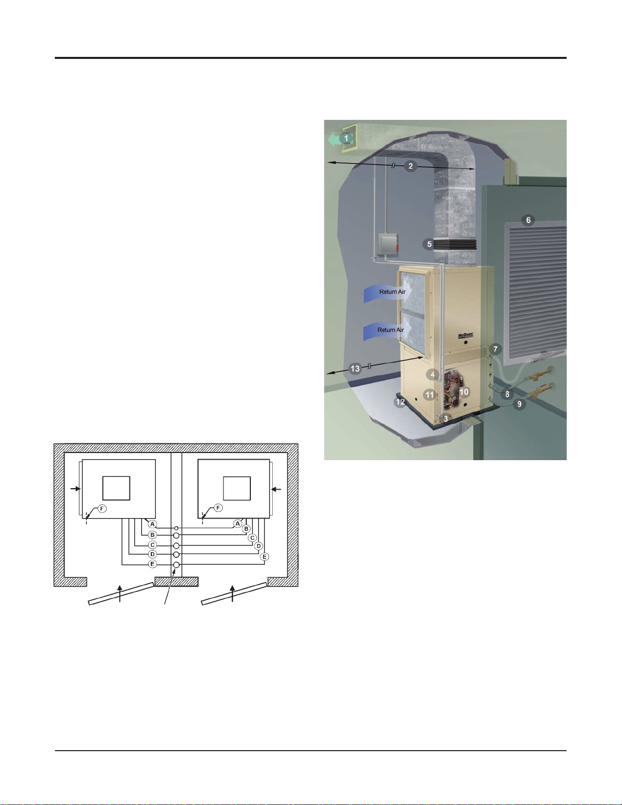
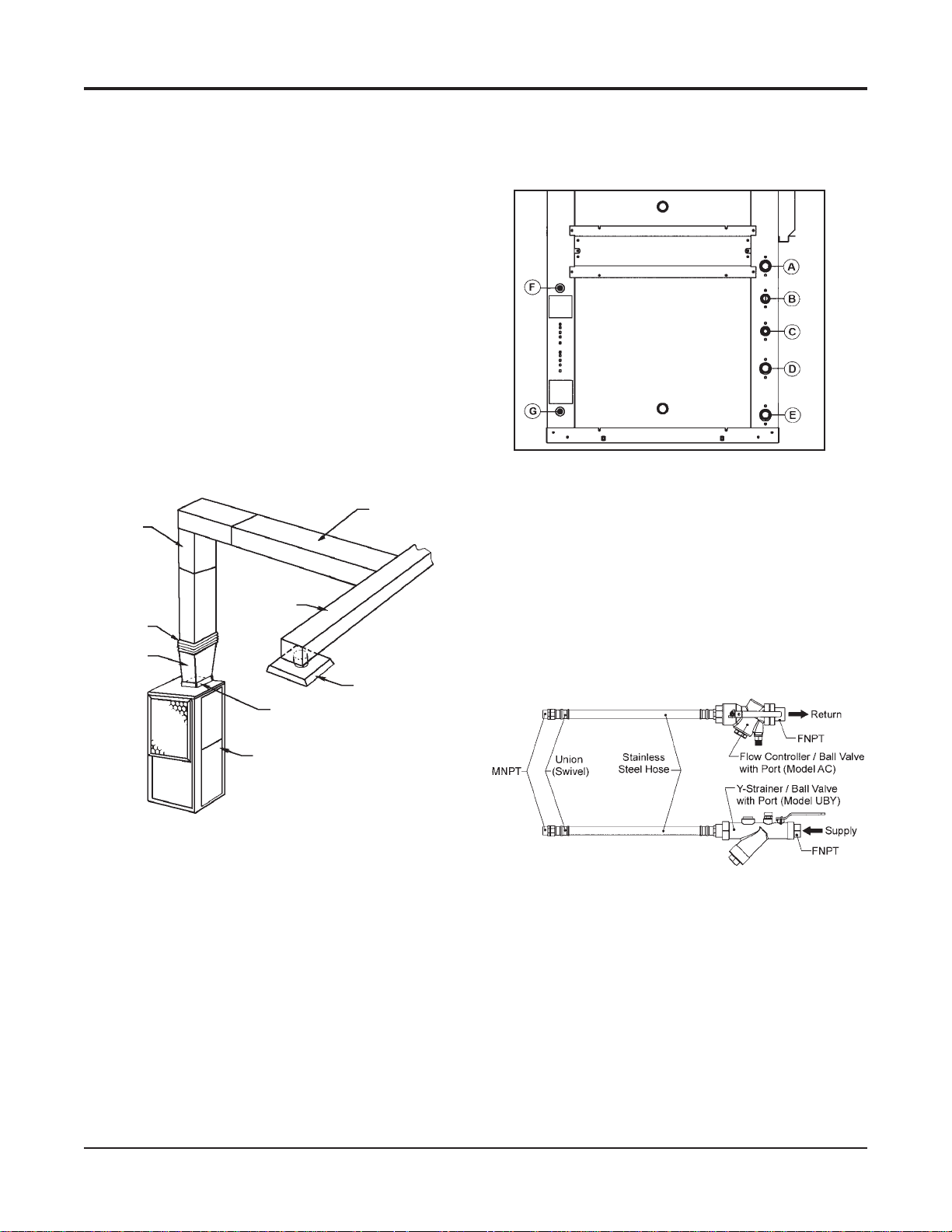
Typical Vertical Installation
Unit Location
The VFC, VFW water source heat pump can be
installed “free standing” in an equipment room; however,
closet installations are more common for the small vertical
type units. Generally, the unit is located in the corner of a
closet with the non-ducted return air facing 90º to the door
and the major access panels facing the door as shown in
the illustration at right. Alternatively, the unit can have a
ducted return air with the opening facing the door and the
major access panels facing 90º to the door.
Locate a vertical unit to allow for easy removal of
the lter and access panels. Allow a minimum of 18" (46
cm) clearance on each side of the unit for service and
maintenance access. Always be sure to leave at least one
side of the lter rack unobstructed so that the service
personnel will be able to slide the lter out.
Install a eld supplied line voltage disconnect for
branch circuit protection.
To reduce noise emissions, install a eld-provided 1/2
inch thick, isolator pad below the entire base of the vertical
unit. The pad should be equal to the overall foot-print size
of the unit to provide sound dampening of the unit while in
operation.
Typical VFC Installation – Closet, Non-Ducted Return
Typical Closet Installation - Non-ducted Application
Left-Hand Return Air
Arrangement
Return
Air
Return Air Thru
Louvered Door
Risers
A - Condensate
B- Desuperheater Water Return (Optional)
C
- Desuperheater Water Supply (Optional)
D
- Water Return
E
- Water Supply
F
- Low Voltage Control Wiring (Electric Entrance)
Right-Hand Return Air
Arrangement
Return
Air
Return Air Thru
Louvered Door
1. Discharge air
2. Acoustic thermal duct lining - 10 feet
3. Line voltage disconnect
4. Low voltage wiring to unit control box
5. Flexible duct collar
6. Louvered closet door
7. Condensate drain
8. Flexible, braided, stainless steel return hose with ow
controller/ball valve with port
9. Flexible, braided, stainless steel supply hose with Y-
strainer/ball valve with port
10. Access to unit control box
11. LED annunciator lights indicate unit operation status
and faults
12. Full vibration isolation pad between unit and oor
13. Minimum distance between return air duct collar and
wall for non-ducted return applications
• Size 007-012 – 5 inches
• Size 015-024 – 5 inches
• Size 030-036 – 6 inches
• Size 042-048 – 8 inches
• Size 060-070 – 10 inches
18 McQuay Ennity Water Source Heat Pumps Catalog 1103-2
Page 19
Applications Considerations
Ductwork and Attenuation
All ductwork should conform to industry standards of
good practice as described in ASHRAE Systems Guide.
The discharge duct system will normally consist of a
exible connector at the unit, a non-insulated transition
piece to the full duct size, a short run of duct, an elbow
without vanes, and a trunk duct teeing into a branch circuit
with discharge diffusers as illustrated below.
Return air ducts can be brought in through a wall grille
and then to the unit. The return duct system will normally
consist of a exible connector at the unit and a trunk duct to
the return air grille. With metal duct material, the return air
duct should be internally lined with acoustic insulation for
sound attenuation.
Return air ductwork to the unit requires the optional
return air duct collar/2" (51mm) lter rack kit.
Suggested Discharge Air Ducting
Trunk Duct
Square Elbow
(Both Sides
Internally Lined
With Acoustic
Insulation)
Branch Duct
Flexible
Duct Collar
Duct
Transition
(Internally Lined)
2 ft. x 2 ft. Diffuser
Discharge Collar
devices are commercially available and can be installed to
eliminate the need for memory stop shut off valves. Include
Pressure / Temperature ports to allow the service technician
to measure water ow and unit operation.
Control Access Panel
A - Condensate
B- Desuperheater Water Return (Optional)
C
- Desuperheater Water Supply (Optional)
D
- Water Return
E
- Water Supply
F
- Low Voltage Control Wiring (Electric Entrance)
G
- Line Voltage Unit Power (Electric Entrance)
McQuay has available optional hose kit combinations
to better facilitate system ow balancing. These exible
hoses reduce vibration between the unit and the rigid piping
system.
Fire Rated Supply or Return Hoses
Heat Pump
Piping
The water source heat pump unit is typically connected
to the supply / return piping using a “reverse return” piping
system which includes a ow control device so that ow
requirements are met for each zone. A short, high pressure
“exible hose” is used to connect the unit to the building’s
hard piping and acts as a sound attenuator for both the unit
operating noise and hydronic pumping noise. One end of
the hose has a swivel tting to facilitate removal of the
unit for replacement or service. Include supply and return
shutoff valves in the design to allow removal of a unit
without the need to shut down the entire heat pump system.
The return valve may be used for balancing and will
typically have a “memory stop” so that it can be reopened
to the proper position for the ow required. Fixed ow
Catalog 1103-2 McQuay Ennity Water Source Heat Pumps 19
Condensate Drain
The factory provided condensate drain trap on the
vertical unit is located inside the cabinet. Condensate
removal piping must be pitched away from the unit not
less than 1/4" per foot. A vent is required after the trap so
that the condensate will drain away from the unit. The vent
can also act as a clean out if the trap becomes clogged.
To avoid having waste gases entering the building, the
condensate drain should not be directly piped to a drain/
waste/vent stack. See local codes for the correct application
of condensate piping to drains.
Page 20

Applications – Unit Selection
Achieving optimal performance with water source heat
pump systems requires both accurate system design and
proper equipment selection. Use a building load program to
determine the heating and cooling loads of each zone prior
to making equipment selections. With this information,
the McQuay SelectTools™ software selection program for
Water Source Heat Pumps can be used to provide fast, accurate and complete selections of all McQuay water source
heat pump products. SelectTools software is available by
contacting your local McQuay Representative.
While we recommend that you use McQuay SelectTools
software for all unit selections, manual selections can be
accomplished using the same zone load information and the
capacity tables available in this catalog.
Boiler / Tower Application Manual Selections:
The following example illustrates a typical selection for
a zone in a boiler/tower system for a commercial building.
A building load program determines that this zone needs
38,255 BTUH of total cooling, 31,832 BTUH of sensible
cooling and 36,988 BTUH of total heating. The water tem-
peratures for the boiler/tower system are 90ºF for cooling
and 70ºF for heating. The return air temperature is 80ºF dry
bulb with 67ºF wet bulb for cooling and 70ºF for heating.
Zone requirements:
Total Cooling Load = 38,255 BTUH
Sensible Cooling Load = 31,832 BTUH
Total Heating Load = 36,988 BTUH
Air Flow Required = 1510 CFM
Return Air Cooling = 80ºFDB/ 67ºFWB
Return Air - Heating = 70ºFDB
Since a McQuay Model VFC 036 produces approxi-
mately 36,000 BTUH of cooling, it is not sufcient for
this zone and a model VFC 042 should be considered.
Model VFC is chosen because it is specically designed
for a boiler/tower application. Typical water ow rates for
boiler/tower applications are 2.0 to 2.5 GPM per ton and in
this example no antifreeze is used.
Selection:
Model .............................VFC 042 (Boiler / Tower model)
Total Cooling Capacity @ 90 EWT = 40,816 BTUH
Sensible cooling capacity @ 90 EWT = 32,704 BTUH
Total Heating Capacity @ 70 EWT = 52,019 BTUH
CFM = 1510 @ .5 ESP (Wet Coil)
Water Flow required to meet capacity = 8 GPM
Water Pressure drop = 6.9 (FT. H2O)
Final Selection ....................................................VFC 042
Geothermal Applications:
The following example illustrates the same zone in a
geothermal application.
The load requirements for the zone are the same as the
above example – 38,255 BTUH of total cooling and 31,832
BTUH of sensible cooling and 36,988 BTUH of heating.
Geothermal loop software programs are available to help
determine the size of the loop eld based on:
Desired entering water temperatures for the system.
Specic acreage available for the loop which produces
specic min./max loop temps for the unit selection.
Entering water temperatures for geothermal systems can
be as high as 90º to 100ºF and as low as 30ºF based on the
geographical location of the building. Water ow rates are
typically 2.5 to 3 GPM per ton and the use of antifreeze is
required in most northern applications.
Zone requirements:
Total Cooling Load = 38,255 BTUH
Sensible Cooling Load = 31,832 BTUH
Total Heating Load = 36,988 BTUH
Air Flow Required = 1510 CFM
Return Air Cooling = 80 DB / 67 WB
Return Air - Heating = 70 DB
A McQuay Model VFW is chosen for this geothermal
application. Model VFW offers insulated water piping for
condensation considerations and a different freezestat setting to allow entering water temperatures lower than 40ºF
(with antifreeze). Output capacities should be recalculated
using the antifreeze reduction tables that are shown on page
49. The Model VFW 042 is rst considered but may not
meet the heating load because of the reduced entering water
temperatures (35ºF) and an antifreeze solution of 21 %
propylene (see page 49).
Selection:
Model ..................................VFW 042 (Geothermal model)
Total cooling capacity @ 100 EWT = 40,434 BTUH x
.980 = 39,625
Sensible cooling capacity @ 100 EWT = 32,164 BTUH x
.980 = 31,520
Total heating capacity @ 35 EWT = 38,335 BTUH x
.975 = 37,377 CFM = 1510 @ .6 ESP (Dry Coil)
Water Flow required to meet capacity = 10.8 GPM
Water Pressure drop = 12.7 x 1.5 = 14.61 (FT. H2O)
Final Selection ....................................................VFW 042
Note:
In applications where the zone may be a corner ofce or have
excessive glass area, the heating load could be greater than the
heating output capacity of the VFW 042 model (say 41,985 BTUH).
The choices are to upsize the unit to the next model available (048),
or add an electric duct heater to supplement the output of the 042
unit.
20 McQuay Ennity Water Source Heat Pumps Catalog 1103-2
Page 21

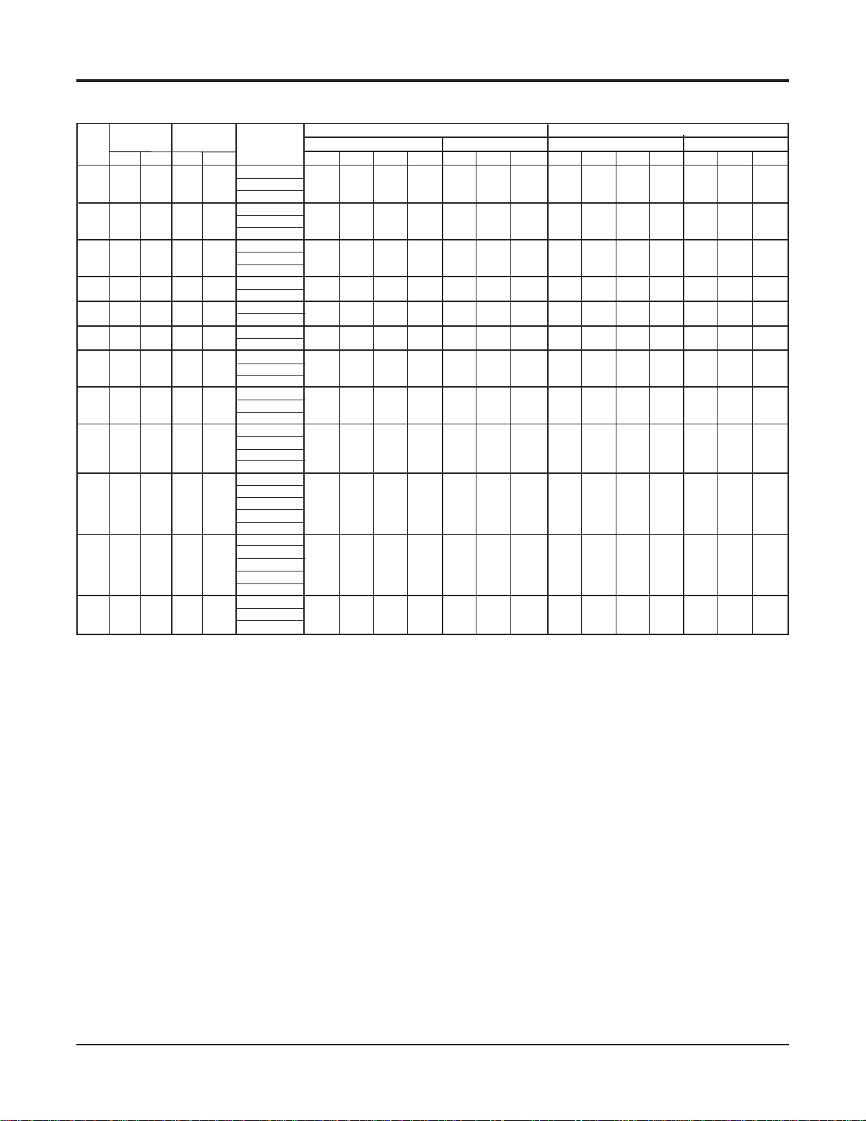
Ennity Vertical ISO Performance Data – Water Loop
Water Loop Performance Data – Rated in Accordance with ISO Standard 13256-1 Boiler/Tower
Standard Unit ECM at High Static
*007
009
012
042
* Not available at time of publication. Please consult your McQuay Representative for specific availability
n/a = ECM not available in unit sizes 007, 009, 012.
Unit
Size
015
019
024
030
036
048
060
070
CFM
*
300
400
500
600
800
1000
1300
1400
1600
2000
2160
Airow Waterow
Cooling Heating Cooling Heating
Voltage
L/S GPM L/S Btuh Watts EER COP Btuh Watts COP Btuh Watts EER COP Btuh Watts COP
*
142
189
236
283
378
472
614
661
755
944
1019
*
2.3
3.0
3.6
4.68
5.81
7.25
9.50
11.00
12.00
15.50
19.00
*
0.15
0.19
0.23
0.30
0.37
0.46
0.60
0.69
0.76
0.98
1.20
115-1-60
208/230-1-60
265-1-60
115-1-60
208/230-1-60
265-1-60
115-1-60
208/230-1-60
265-1-60
208/230-1-60
265-1-60
208/230-1-60
265-1-60
208/230-1-60
265-1-60
208/230-1-60
265-1-60
208/230-3-60
208/230-1-60
208/230-3-60
460-3-60
208/230-1-60
208/230-3-60
460-3-60
575-3-60
208/230-1-60
208/230-3-60
265-1-60
460-3-60
575-3-60
208/230-1-60
208/230-3-60
265-1-60
460-3-60
575-3-60
208/230-3-60
460-3-60
575-3-60
*
9060
12000
14700
19200
23800
30000
39500
43900
48100
63200
75400
*
2650
3510
4300
5620
6980
8800
11500
12800
14100
18500
22100
14.0
14.4
16.0
15.2
15.1
17.0
14.8
15.0
14.7
15.1
13.5
n/a
n/a
n/a
16.6
16.3
17.0
15.0
16.2
16.0
15.7
14.0
n/a
n/a
n/a
n/a
n/a
n/a
*
*
*
4.9
18000
4.8
26300
5.0
33400
4.4
44500
4.7
52300
4.7
56400
4.6
67700
4.1
86300
*
*
4.1
10600
4.2
14000
4.7
16100
4.5
18300
4.4
26700
5.0
33400
4.3
45000
4.4
52500
4.3
56800
4.4
68300
4.0
87300
*
4.7
4.8
5.1
4.4
4.9
5.2
4.6
4.8
4.8
4.7
4.4
*
*
3110
4110
4720
5370
7820
9780
13200
15400
16600
20000
25500
n/a
n/a
n/a
*
19500
24100
29900
39900
44200
48700
63600
76200
n/a
n/a
n/a
*
5710
7050
8750
11700
12900
14200
18600
22300
n/a
n/a
n/a
*
5270
7700
9780
13000
15300
16500
19800
25300
n/a
n/a
n/a
*
4.6
5.2
5.4
4.6
5.1
5.1
5.0
4.5
Notes:
EER = Energy Efciency Ratio COP = Coefcient of Performance L/s = Liters per second
Cooling capacity is based on 80.6°F db, 66.2°F wb (27/19°C) entering air temperature and 86°F (30°C) entering water temperature.
Heating capacity is based on 68°F (20°C) entering air temperature and 68°F (20°C) entering water temperature.
Catalog 1103-2 McQuay Ennity Water Source Heat Pumps 21
Page 22

Ennity Vertical ISO Performance Data – Ground Loop
Ground Loop Performance Data Rated in Accordance with ISO Standard 13256-1 Ground Coupled
Standard Unit ECM at High Static
*007
009
012
* Not available at time of publication. Please consult your McQuay Representative for specific availability
n/a = ECM not available in unit sizes 007, 009, 012.
Unit
Size
015
019
024
030
036
042
048
060
070
CFM
*
300
400
500
600
800
1000
1300
1400
1600
2000
2160
Airow Waterow
Cooling Heating Cooling Heating
Voltage
L/S GPM L/S Btuh Watts EER COP Btuh Watts COP Btuh Watts EER COP Btuh Watts COP
*
142
189
236
283
378
472
614
661
755
944
1019
*
2.3
3.0
3.6
4.68
5.81
7.25
9.50
11.00
12.00
15.50
19.00
*
0.15
0.19
0.23
0.30
0.37
0.46
0.60
0.69
0.76
0.98
1.20
115-1-60
208/230-1-60
265-1-60
115-1-60
208/230-1-60
265-1-60
115-1-60
208/230-1-60
265-1-60
208/230-1-60
265-1-60
208/230-1-60
265-1-60
208/230-1-60
265-1-60
208/230-1-60
265-1-60
208/230-3-60
208/230-1-60
208/230-3-60
460-3-60
208/230-1-60
208/230-3-60
460-3-60
575-3-60
208/230-1-60
208/230-3-60
265-1-60
460-3-60
575-3-60
208/230-1-60
208/230-3-60
265-1-60
460-3-60
575-3-60
208/230-3-60
460-3-60
575-3-60
*
9720
12700
15700
19400
24800
30700
40300
45400
51600
65100
76500
*
2850
3720
4600
5690
7260
9000
11800
13300
15100
19100
22400
*
4.9
5.0
5.7
5.1
5.2
5.6
5.1
5.0
4.6
4.8
4.0
*
*
2050
7020
2720
9300
2920
10000
4010
13700
5210
17800
6530
22300
8900
30300
10300
35100
11800
40300
13700
47000
17200
58900
*
16.7
16.9
19.6
17.3
17.7
19.1
17.3
17.0
15.8
16.3
13.7
*
3.3
3.5
3.5
3.5
3.6
3.9
3.4
3.6
3.4
3.5
3.1
n/a
n/a
n/a
*
19700
25100
30600
40500
46100
50200
66000
78400
n/a
n/a
n/a
*
5770
7350
8960
11800
13500
14700
19300
22900
n/a
n/a
19.0
19.2
19.3
16.6
18.9
18.2
18.0
16.2
n/a
n/a
n/a
n/a
n/a
*
*
5.6
5.6
5.7
4.9
5.5
5.3
5.3
4.7
*
13400
17500
22300
30000
34400
37600
46000
56800
n/a
n/a
n/a
n/a
n/a
*
3920
5120
6530
8790
10100
11000
13500
16600
n/a
n/a
n/a
*
3.7
3.8
4.0
3.3
3.8
3.8
3.8
3.6
Notes:
EER = Energy Efciency Ratio COP = Coefcient of Performance L/S = Liters per second
Cooling capacity is based on 80.6°F db, 66.2°F wb (27/19°C) entering air temperature and 77°F (25°C) entering water temperature.
Heating capacity is based on 68°F (20°C) entering air temperature and 32°F (0°C) entering water temperature.
22 McQuay Ennity Water Source Heat Pumps Catalog 1103-2
Page 23
Ennity Vertical ISO Performance Data – Ground Water
Ground Water Performance Data Rated in Accordance with ISO Standard 13256-1.
Standard Unit ECM at High Static
*007
009
012
* Not available at time of publication. Please consult your McQuay Representative for specific availability
n/a = ECM not available in unit sizes 007, 009, 012.
Unit
Size
015
019
024
030
036
042
048
060
070
CFM
*
300
400
500
600
800
1000
1300
1400
1600
2000
2160
Airow Waterow
Cooling Heating Cooling Heating
Voltage
L/S GPM L/S Btuh Watts EER COP Btuh Watts COP Btuh Watts EER COP Btuh Watts COP
115-1-60
*
142
189
236
283
378
472
614
661
755
944
1019
*
2.3
3.0
3.6
4.68
5.81
7.25
9.50
11.00
12.00
15.50
19.00
*
0.15
0.19
0.23
0.30
0.37
0.46
0.60
0.69
0.76
0.98
1.20
208/230-1-60
265-1-60
115-1-60
208/230-1-60
265-1-60
115-1-60
208/230-1-60
265-1-60
208/230-1-60
265-1-60
208/230-1-60
265-1-60
208/230-1-60
265-1-60
208/230-1-60
265-1-60
208/230-3-60
208/230-1-60
208/230-3-60
460-3-60
208/230-1-60
208/230-3-60
460-3-60
575-3-60
208/230-1-60
208/230-3-60
265-1-60
460-3-60
575-3-60
208/230-1-60
208/230-3-60
265-1-60
460-3-60
575-3-60
208/230-3-60
460-3-60
575-3-60
*
10900
14100
17100
21400
26600
33000
42900
48800
56100
69000
79100
*
3200
4130
5010
6270
7790
9600
12500
14300
16400
20200
23100
*
8820
*
2580
3450
3830
4950
6360
8320
11000
12500
14300
17100
21300
*
4.0
4.2
4.3
4.1
4.2
4.6
4.1
4.2
4.0
4.1
3.6
*
*
7.0
23.8
7.0
8.2
6.9
6.8
7.4
6.5
6.5
5.9
6.0
4.9
11800
13100
16900
21700
28400
37700
42900
48900
58400
72700
23.8
28.1
23.5
23.3
25.1
22.3
22.1
20.3
20.5
16.6
n/a
n/a
n/a
*
21600
26900
32900
43000
49100
54300
69900
80600
n/a
n/a
n/a
*
6320
7880
9630
12600
14400
15900
20500
23600
n/a
n/a
n/a
n/a
*
26.1
25.8
25.5
21.3
24.8
23.8
22.9
19.6
n/a
n/a
7.7
7.6
7.5
6.2
7.3
7.0
6.7
5.7
n/a
n/a
n/a
*
*
16600
21300
28400
37400
43000
47100
57400
70500
n/a
n/a
n/a
*
4860
6240
8300
10900
12600
13800
16800
20600
n/a
n/a
n/a
*
4.4
4.5
4.8
4.0
4.5
4.5
4.4
4.1
Notes:
EER = Energy Efciency Ratio COP = Coefcient of Performance L/S = Liters per second
Cooling capacity is based on 80.6°F db, 66.2°F wb (27/19°C) entering air temperature and 59°F (15°C) entering water temperature.
Heating capacity is based on 68°F (20°C) entering air temperature and 50°F (10°C) entering water temperature.
Capacity Tables Notes:
EWT = Entering Water Temperature (ºF) L/sec. = Airow in Liters per second WPD = Water Pressure Drop (Ft. Hd) EA = Entering Air Temperature (ºF)
LWT = Leaving Water Temperature (ºF) TOT = Total Heat (Btu) SEN = Sensible Heat (Btu) kW = Kilowatts
COP = Coefcient of Performance THA = Total Heat of Absorption (Btu) THR = Total Heat of Rejection (Btu) GPM = Gallons Per Minute
Catalog 1103-2 McQuay Ennity Water Source Heat Pumps 23
Page 24

Capacity Data – Vertical Unit Size 009 (300 CFM)
EWT
20
30
40
50
60
70
GPM
1.6
2
.3
3.0
1.6
2.3
3.0
1.6
2.3
3.0
1.6
2.3
3.0
1.6
2.3
3.0
1.6
2.3
3.0
WPD
4
.1
7.4
11.4
4.1
7.4
11.4
4.1
7.4
11.4
4.1
7.4
11.4
4.1
7.4
11.4
4.1
7.4
11.4
EA
n/a
n/a
n/a
n/a
n/a
n/a
n/a
n/a
n/a
n/a
n/a
n/a
70/59
75/63
80/67
85/71
70/59
75/63
80/67
85/71
70/59
75/63
80/67
85/71
70/59
75/63
80/67
85/71
70/59
75/63
80/67
85/71
70/59
75/63
80/67
85/71
70/59
75/63
80/67
85/71
70/59
75/63
80/67
85/71
70/59
75/63
80/67
85/71
70/59
75/63
80/67
85/71
70/59
75/63
80/67
85/71
70/59
75/63
80/67
85/71
70/59
75/63
80/67
85/71
70/59
75/63
80/67
85/71
70/59
75/63
80/67
85/71
LWT
n/a
n/a
n/a
n/a
n/a
n/a
n/a
n/a
n/a
n/a
n/a
n/a
44.0
45.0
46.0
47.0
39.8
40.4
41.1
41.9
37.5
38.0
38.5
39.1
53.9
54.9
55.9
57.0
49.7
50.4
51.1
51.8
47.5
48.0
48.5
49.1
63.7
64.7
65.7
66.8
59.6
60.3
61.0
61.7
57.4
57.9
58.4
59.0
73.4
74.3
75.4
76.5
69.4
70.1
70.8
71.5
67.2
67.7
68.3
68.9
83.0
83.9
84.9
86.0
79.1
79.8
80.5
81.3
77.0
77.5
78.1
78.7
Cooling Heating
TOT
n/a
n/a
n/a
n/a
n/a
n/a
n/a
n/a
n/a
n/a
n/a
n/a
10569
11515
12461
13408
10700
11646
12593
13539
10831
11777
12724
13670
10061
10963
11865
12767
10192
11094
11996
12898
10323
11225
12128
13030
9548
10405
11263
12121
9679
10537
11394
12252
9810
10668
11526
12383
9028
9842
10655
11469
9160
9973
10787
11600
9291
10104
10918
11731
8504
9273
10042
10811
8635
9404
10173
10942
8766
9535
10304
11073
SEN
n/a
n/a
n/a
n/a
n/a
n/a
n/a
n/a
n/a
n/a
n/a
n/a
7704
7917
8130
8343
7757
7970
8183
8396
7810
8023
8236
8449
7472
7691
7910
8128
7526
7744
7963
8181
7579
7797
8016
8235
7237
7461
7685
7909
7290
7514
7738
7962
7343
7567
7791
8016
6997
7227
7456
7686
7050
7280
7510
7739
7103
7333
7563
7792
6753
6988
7223
7459
6806
7041
7276
7512
6859
7094
7330
7565
kW
n/a
n/a
n/a
n/a
n/a
n/a
n/a
n/a
n/a
n/a
n/a
n/a
0.208
0.166
0.125
0.084
0.207
0.166
0.125
0.084
0.207
0.166
0.124
0.083
0.313
0.280
0.248
0.215
0.312
0.280
0.247
0.215
0.312
0.279
0.247
0.214
0.406
0.383
0.359
0.335
0.406
0.382
0.358
0.334
0.406
0.382
0.358
0.334
0.489
0.473
0.458
0.443
0.488
0.473
0.458
0.443
0.488
0.473
0.457
0.442
0.559
0.553
0.546
0.540
0.559
0.552
0.546
0.539
0.558
0.552
0.545
0.539
THR
n/a
n/a
n/a
n/a
n/a
n/a
n/a
n/a
n/a
n/a
n/a
n/a
11240
12065
12889
13714
11308
12133
12957
13782
11376
12200
13025
13850
11120
11937
12755
13573
11187
12005
12823
13640
11255
12073
12891
13708
10938
11748
12559
13370
11005
11816
12627
13438
11073
11884
12695
13506
10694
11498
12302
13106
10762
11566
12370
13174
10830
11634
12438
13242
10390
11187
11984
12781
10458
11255
12052
12849
10525
11323
12120
12917
EA
50
60
70
80
50
60
70
80
50
60
70
80
50
60
70
80
50
60
70
80
50
60
70
80
50
60
70
80
50
60
70
80
50
60
70
80
50
60
70
80
50
60
70
80
50
60
70
80
50
60
70
80
50
60
70
80
50
60
70
80
50
60
70
80
50
60
70
80
50
60
70
80
LWT
14.5
14.8
15.1
15.4
16.2
16.4
16.6
16.8
17.1
17.2
17.4
17.5
23.4
23.7
24.1
24.4
25.4
25.6
25.9
26.1
26.4
26.6
26.8
27.0
32.3
32.7
33.0
33.4
34.5
34.8
35.0
35.3
35.8
36.0
36.2
36.4
41.1
41.5
41.9
42.3
43.7
43.9
44.2
44.5
45.1
45.3
45.5
45.8
49.8
50.2
50.7
51.2
52.7
53.0
53.4
53.7
54.3
54.6
54.8
55.1
58.4
58.9
59.4
59.9
61.7
62.0
62.4
62.8
63.5
63.8
64.1
64.4
TOT
6014
5916
5818
5719
6197
6099
6001
5903
6380
6282
6184
6086
6899
6801
6703
6604
7082
6984
6886
6788
7265
7167
7069
6971
7837
7739
7641
7543
8020
7922
7824
7726
8203
8105
8007
7909
8828
8730
8632
8534
9011
8913
8815
8717
9194
9096
8998
8900
9872
9774
9676
9578
10055
9957
9859
9761
10239
10140
10042
9944
10969
10871
10773
10675
11152
11054
10956
10858
11336
11238
11139
11041
kW
0.453
0.524
0.594
0.665
0.473
0.544
0.614
0.685
0.493
0.564
0.634
0.705
0.458
0.536
0.614
0.691
0.478
0.556
0.633
0.711
0.498
0.576
0.653
0.731
0.461
0.545
0.630
0.715
0.481
0.565
0.650
0.735
0.500
0.585
0.670
0.755
0.460
0.552
0.644
0.736
0.480
0.572
0.664
0.756
0.500
0.592
0.684
0.776
0.458
0.557
0.655
0.754
0.478
0.576
0.675
0.774
0.497
0.596
0.695
0.794
0.452
0.558
0.664
0.770
0.472
0.578
0.684
0.790
0.492
0.598
0.704
0.810
THA
4250
4028
3806
3583
4434
4212
3989
3767
4618
4395
4173
3951
5153
4885
4617
4349
5336
5068
4800
4532
5520
5252
4984
4716
6117
5803
5490
5176
6301
5987
5674
5360
6484
6171
5857
5544
7143
6784
6425
6066
7327
6968
6609
6249
7511
7151
6792
6433
8231
7827
7422
7017
8415
8010
7606
7201
8599
8194
7789
7384
9382
8931
8481
8030
9565
9115
8665
8214
9749
9299
8848
8398
24 McQuay Ennity Water Source Heat Pumps Catalog 1103-2
Page 25

Capacity Data – Vertical Unit Size 009 (300 CFM)
EWT GPM WPD
80
85
90
100
110
1.6
2.3
3.0
1.6
2.3
3.0
1.6
2.3
3.0
1.6
2.3
3.0
1.6
2.3
3.0
4
7.4
11.4
4.1
7.4
11.4
4.1
7.4
11.4
4.1
7.4
11.4
4.1
7.4
11.4
.1
Cooling Heating
EA
70/59
75/63
80/67
85/71
70/59
75/63
80/67
85/71
70/59
75/63
80/67
85/71
70/59
75/63
80/67
85/71
70/59
75/63
80/67
85/71
70/59
75/63
80/67
85/71
70/59
75/63
80/67
85/71
70/59
75/63
80/67
85/71
70/59
75/63
80/67
85/71
70/59
75/63
80/67
85/71
70/59
75/63
80/67
85/71
70/59
75/63
80/67
85/71
70/59
75/63
80/67
85/71
70/59
75/63
80/67
85/71
70/59
75/63
80/67
85/71
92.5
93.4
94.4
95.5
88.8
89.5
90.2
90.9
86.8
87.3
87.8
88.4
97.2
98.2
99.2
100.2
93.6
94.3
95.0
95.7
91.6
92.1
92.7
93.3
102.1
102.9
103.9
104.9
98.4
99.1
99.8
100.5
96.5
97.0
97.5
98.1
111.5
112.5
113.4
114.2
108.1
108.8
109.3
110.0
106.3
106.8
107.2
107.8
120.9
121.8
122.7
123.7
117.7
118.3
119.0
119.7
116.0
116.4
117.0
117.5
TOT kW THR EA LWT TOTLWT
7973
8698
9422
10147
8104
8829
9554
10278
8235
8960
9685
10410
7705
8408
9111
9813
7837
8539
9242
9944
7968
8670
9373
10076
7436
8117
8797
9478
7568
8248
8929
9609
7699
8379
9060
9740
6894
7530
8167
8803
7025
7662
8298
8934
7157
7793
8429
9065
6346
6938
7530
8122
6477
7069
7661
8253
6609
7201
7792
8384
SEN
6505
6745
6986
7227
6558
6798
7039
7280
6611
6852
7092
7333
6379
6622
6866
7109
6432
6675
6919
7162
6485
6729
6972
7215
6252
6498
6744
6991
6305
6551
6798
7044
6358
6604
6851
7097
5995
6247
6499
6750
6048
6300
6552
6803
6101
6353
6605
6857
5734
5991
6248
6506
5787
6044
6302
6559
5840
6097
6355
6612
0.618
0.620
0.622
0.625
0.618
0.620
0.622
0.624
0.617
0.620
0.622
0.624
0.644
0.650
0.656
0.663
0.643
0.650
0.656
0.662
0.643
0.649
0.655
0.662
0.666
0.677
0.687
0.698
0.665
0.676
0.687
0.698
0.665
0.676
0.686
0.697
0.702
0.721
0.741
0.760
0.701
0.721
0.740
0.760
0.701
0.720
0.740
0.759
0.726
0.754
0.782
0.810
0.726
0.754
0.782
0.810
0.726
0.754
0.782
0.810
10024
10814
11605
12395
10092
10882
11673
12463
10160
10950
11740
12531
9818
10605
11392
12179
9886
10673
11460
12247
9954
10741
11528
12315
9597
10381
11164
11948
9665
10448
11232
12016
9733
10516
11300
12083
9109
9885
10662
11439
9176
9953
10730
11507
9244
10021
10798
11575
8559
9329
10099
10869
8627
9397
10167
10937
8695
9465
10235
11005
50
60
70
80
50
60
70
80
50
60
70
80
50
60
70
80
50
60
70
80
50
60
70
80
50
60
70
80
50
60
70
80
50
60
70
80
50
60
70
80
50
60
70
80
50
60
70
80
50
60
70
80
50
60
70
80
50
60
70
80
66.9
67.4
68.0
68.6
70.6
71.0
71.4
71.9
72.7
73.0
73.3
73.7
71.1
71.7
72.3
72.9
75.0
75.4
75.9
76.4
77.2
77.5
77.9
78.3
75.3
75.9
76.6
77.2
79.4
79.9
80.4
80.8
81.7
82.1
82.5
82.9
83.6
84.3
85.0
85.8
88.2
88.7
89.2
89.8
90.8
91.2
91.6
92.0
91.9
92.6
93.4
94.2
96.9
97.5
98.1
98.7
99.8
100.2
100.7
101.2
12119
12021
11923
11825
12303
12204
12106
12008
12486
12388
12290
12191
12714
12616
12518
12420
12897
12799
12701
12603
13081
12983
12884
12786
13322
13224
13126
13028
13506
13408
13309
13211
13689
13591
13493
13395
14579
14480
14382
14284
14762
14664
14566
14467
14945
14847
14749
14651
15888
15790
15691
15593
16071
15973
15875
15777
16254
16156
16058
15960
kW
0.444
0.557
0.670
0.783
0.464
0.577
0.690
0.803
0.484
0.597
0.710
0.823
0.439
0.556
0.673
0.789
0.459
0.576
0.692
0.809
0.479
0.596
0.712
0.829
0.434
0.554
0.674
0.794
0.454
0.574
0.694
0.814
0.474
0.594
0.714
0.834
0.421
0.548
0.675
0.802
0.441
0.568
0.695
0.822
0.460
0.588
0.715
0.842
0.405
0.539
0.673
0.808
0.425
0.559
0.693
0.828
0.445
0.579
0.713
0.848
THA
10594
10098
9602
9106
10778
10282
9785
9289
10961
10465
9969
9473
11223
10704
10186
9667
11407
10888
10369
9850
11591
11072
10553
10034
11868
11326
10785
10243
12052
11510
10968
10427
12235
11694
11152
10610
13204
12617
12030
11442
13388
12801
12213
11626
13571
12984
12397
11810
14602
13969
13336
12704
14786
14153
13520
12887
14970
14337
13704
13071
Catalog 1103-2 McQuay Ennity Water Source Heat Pumps 25
Page 26

Capacity Data – Vertical Unit Size 012 (400 CFM)
EWT
20
30
40
50
60
70
GPM
2
.1
3.0
3.9
2.1
3.0
3.9
2.1
3.0
3.9
2.1
3.0
3.9
2.1
3.0
3.9
2.1
3.0
3.9
WPD
6.
11.4
17.5
6.4
11.4
17.5
6.4
11.4
17.5
6.4
11.4
17.5
6.4
11.4
17.5
6.4
11.4
17.5
EA
n/a
n/a
4
n/a
n/a
n/a
n/a
n/a
n/a
n/a
n/a
n/a
n/a
70/59
75/63
80/67
85/71
70/59
75/63
80/67
85/71
70/59
75/63
80/67
85/71
70/59
75/63
80/67
85/71
70/59
75/63
80/67
85/71
70/59
75/63
80/67
85/71
70/59
75/63
80/67
85/71
70/59
75/63
80/67
85/71
70/59
75/63
80/67
85/71
70/59
75/63
80/67
85/71
70/59
75/63
80/67
85/71
70/59
75/63
80/67
85/71
70/59
75/63
80/67
85/71
70/59
75/63
80/67
85/71
70/59
75/63
80/67
85/71
LWT
n/a
n/a
n/a
n/a
n/a
n/a
n/a
n/a
n/a
n/a
n/a
n/a
43.6
44.7
45.8
47.0
39.2
39.9
40.7
41.4
36.9
37.5
38.0
38.6
53.6
54.7
55.9
57.2
49.4
50.2
51.0
51.7
47.2
47.8
48.3
48.9
63.6
64.6
65.6
66.8
59.4
60.1
60.9
61.7
57.2
57.8
58.3
59.0
73.4
74.3
75.3
76.3
69.4
70.0
70.7
71.5
67.2
67.7
68.2
68.8
83.1
84.0
84.9
85.9
79.2
79.8
80.5
81.2
77.1
77.6
78.1
78.6
Cooling Heating
TOT
n/a
n/a
n/a
n/a
n/a
n/a
n/a
n/a
n/a
n/a
n/a
n/a
12999
14284
15667
17155
12805
14099
15502
16999
12697
13994
15377
16912
12635
13773
15001
16317
12570
13720
14964
16315
12525
13678
14934
16298
12180
13210
14329
15532
12200
13250
14392
15624
12202
13261
14413
15656
11666
12618
13641
14750
11745
12717
13767
14908
11778
12760
13824
14979
11097
11987
12934
13958
11215
12128
13102
14160
11271
12194
13181
14256
SEN
n/a
n/a
n/a
n/a
n/a
n/a
n/a
n/a
n/a
n/a
n/a
n/a
9659
10065
10434
10764
9571
9987
10370
10709
9521
9942
10320
10679
9479
9830
10152
10445
9448
9808
10143
10450
9428
9792
10133
10446
9267
9586
9884
10155
9276
9603
9908
10188
9276
9607
9916
10200
9029
9334
9615
9878
9065
9376
9664
9933
9080
9394
9685
9957
8768
9069
9344
9602
8822
9128
9408
9672
8848
9155
9438
9705
kW
n/a
n/a
n/a
n/a
n/a
n/a
n/a
n/a
n/a
n/a
n/a
n/a
0.299
0.290
0.282
0.225
0.214
0.207
0.201
0.161
0.187
0.181
0.176
0.141
0.435
0.429
0.422
0.413
0.401
0.391
0.367
0.287
0.399
0.386
0.328
0.242
0.542
0.536
0.529
0.523
0.518
0.508
0.498
0.488
0.520
0.509
0.497
0.484
0.633
0.629
0.624
0.619
0.615
0.608
0.600
0.592
0.620
0.612
0.602
0.592
0.716
0.714
0.712
0.710
0.702
0.698
0.693
0.687
0.709
0.704
0.697
0.690
THR
n/a
n/a
n/a
n/a
n/a
n/a
n/a
n/a
n/a
n/a
n/a
n/a
13983
15107
16279
17517
13479
14556
15700
16846
13220
14279
15344
16534
14041
15156
16361
17645
13830
14945
16110
17203
13711
14822
15888
16977
13916
14925
16020
17200
13821
14840
15947
17142
13764
14786
15898
17098
13682
14619
15625
16715
13666
14614
15637
16748
13651
14604
15634
16755
13366
14251
15190
16204
13403
14302
15258
16295
13417
14321
15285
16334
EA
50
60
70
80
50
60
70
80
50
60
70
80
50
60
70
80
50
60
70
80
50
60
70
80
50
60
70
80
50
60
70
80
50
60
70
80
50
60
70
80
50
60
70
80
50
60
70
80
50
60
70
80
50
60
70
80
50
60
70
80
50
60
70
80
50
60
70
80
50
60
70
80
LWT
14.9
14.9
15.1
15.3
16.4
16.4
16.5
16.7
17.2
17.2
17.3
17.5
23.6
23.7
23.9
24.2
25.4
25.5
25.6
25.9
26.4
26.5
26.6
26.8
32.3
32.5
32.8
33.2
34.5
34.6
34.8
35.1
35.7
35.8
36.0
36.2
41.0
41.3
41.7
42.1
43.5
43.7
44.0
44.4
44.9
45.1
45.3
45.6
49.6
50.0
50.4
51.0
52.5
52.8
53.1
53.5
54.1
54.4
54.7
55.0
58.1
58.6
59.1
59.7
61.4
61.8
62.2
62.6
63.3
63.6
63.9
64.3
TOT
7371
7623
7653
7551
7371
7623
7653
7551
7371
7623
7653
7551
8867
9006
8982
8858
9046
9168
9129
8945
9140
9235
9143
8944
10277
10320
10223
10038
10496
10516
10399
10197
10609
10618
10492
10280
11705
11655
11487
11245
11965
11890
11702
11445
12103
12019
11821
11547
13187
13056
12821
12525
13506
13341
13080
12760
13673
13493
13218
12884
14743
14528
14230
13880
15122
14875
14553
14174
15329
15068
14722
14326
kW
0.611
0.689
0.753
0.809
0.618
0.695
0.759
0.815
0.624
0.702
0.766
0.821
0.637
0.716
0.784
0.847
0.646
0.726
0.794
0.856
0.654
0.733
0.801
0.862
0.658
0.739
0.811
0.879
0.668
0.749
0.821
0.889
0.676
0.757
0.829
0.898
0.677
0.760
0.836
0.909
0.686
0.770
0.847
0.920
0.695
0.778
0.855
0.929
0.695
0.780
0.861
0.939
0.705
0.791
0.872
0.951
0.713
0.800
0.881
0.960
0.712
0.801
0.886
0.970
0.723
0.813
0.898
0.983
0.732
0.822
0.908
0.993
THA
5421
5420
5243
4960
5421
5420
5243
4960
5421
5420
5243
4960
6833
6715
6470
6144
7003
6868
6607
6222
7092
6931
6620
6222
8175
7955
7624
7220
8384
8140
7789
7365
8492
8237
7875
7442
9542
9222
8807
8329
9791
9446
9009
8514
9924
9568
9121
8607
10966
10557
10062
9511
11274
10829
10306
9728
11434
10974
10435
9844
12465
11961
11389
10767
12829
12292
11693
11039
13028
12476
11852
11180
26 McQuay Ennity Water Source Heat Pumps Catalog 1103-2
Page 27

Capacity Data – Vertical Unit Size 012 (400 CFM)
EWT GPM WPD
80
85
90
100
110
2.1
3.0
3.9
2.1
3.0
3.9
2.1
3.0
3.9
2.1
3.0
3.9
2.1
3.0
3.9
6.
11.4
17.5
6.4
11.4
17.5
6.4
11.4
17.5
6.4
11.4
17.5
6.4
11.4
17.5
Cooling Heating
EA
70/59
75/63
4
80/67
85/71
70/59
75/63
80/67
85/71
70/59
75/63
80/67
85/71
70/59
75/63
80/67
85/71
70/59
75/63
80/67
85/71
70/59
75/63
80/67
85/71
70/59
75/63
80/67
85/71
70/59
75/63
80/67
85/71
70/59
75/63
80/67
85/71
70/59
75/63
80/67
85/71
70/59
75/63
80/67
85/71
70/59
75/63
80/67
85/71
70/59
75/63
80/67
85/71
70/59
75/63
80/67
85/71
70/59
75/63
80/67
85/71
92.8
93.6
94.5
95.4
89.0
89.6
90.2
90.9
86.9
87.4
87.9
88.4
97.6
98.4
99.2
100.2
93.9
94.4
95.1
95.7
91.8
92.3
92.8
93.3
102.4
103.2
104.0
104.9
98.7
99.3
99.9
100.5
96.7
97.2
97.6
98.1
112.0
112.7
113.5
114.4
108.5
109.0
109.6
110.2
106.5
106.9
107.4
107.9
121.6
122.3
123.0
123.8
118.2
118.7
119.2
119.8
116.3
116.7
117.1
117.6
TOT kW THR EA LWT TOTLWT
10478
11309
12197
13146
10623
11479
12394
13375
10693
11561
12489
13486
10152
10955
11816
12733
10307
11134
12023
12972
10383
11222
12123
13088
9817
10591
11422
12312
9979
10778
11638
12558
10060
10870
11744
12678
9120
9840
10613
11444
9292
10036
10837
11700
9377
10134
10949
11829
8401
9062
9777
10544
8575
9263
10004
10803
8662
9362
10119
10934
SEN
8489
8787
9066
9324
8554
8858
9139
9402
8586
8892
9175
9440
8343
8642
8923
9184
8412
8716
9000
9264
8446
8752
9038
9304
8193
8494
8777
9043
8266
8570
8857
9125
8302
8608
8896
9165
7885
8191
8480
8755
7960
8269
8562
8840
7998
8309
8603
8882
7566
7878
8176
8461
7643
7958
8258
8545
7681
7998
8300
8588
0.796
0.797
0.798
0.799
0.784
0.783
0.781
0.779
0.793
0.791
0.787
0.783
0.836
0.839
0.842
0.844
0.825
0.826
0.826
0.825
0.834
0.833
0.832
0.830
0.876
0.881
0.885
0.890
0.865
0.868
0.870
0.871
0.875
0.876
0.877
0.876
0.959
0.968
0.976
0.984
0.949
0.955
0.961
0.966
0.959
0.964
0.968
0.971
1.049
1.062
1.074
1.086
1.038
1.048
1.058
1.067
1.047
1.056
1.065
1.072
12992
13826
14718
15666
13063
13914
14822
15794
13096
13955
14870
15854
12788
13600
14469
15391
12871
13699
14586
15531
12911
13747
14642
15597
12574
13364
14208
15109
12666
13472
14337
15258
12711
13525
14399
15331
12131
12877
13677
14531
12233
12996
13814
14692
12284
13055
13883
14773
11684
12385
13137
13942
11786
12505
13277
14104
11836
12565
13348
14187
50
60
70
80
50
60
70
80
50
60
70
80
50
60
70
80
50
60
70
80
50
60
70
80
50
60
70
80
50
60
70
80
50
60
70
80
50
60
70
80
50
60
70
80
50
60
70
80
50
60
70
80
50
60
70
80
50
60
70
80
66.6
67.1
67.8
68.4
70.3
70.7
71.2
71.7
72.4
72.8
73.1
73.5
70.8
71.4
72.0
72.7
74.7
75.2
75.7
76.2
77.0
77.3
77.7
78.1
74.9
75.6
76.3
77.0
79.1
79.6
80.1
80.7
81.5
81.9
82.3
82.7
83.2
84.0
84.7
85.5
87.9
88.4
89.0
89.6
90.5
90.9
91.4
91.9
91.5
92.3
93.1
94.0
96.6
97.2
97.8
98.4
99.5
99.9
100.4
101.0
16382
16099
15740
15336
16846
16516
16120
15682
17090
16738
16323
15869
17241
16913
16527
16101
17742
17378
16948
16480
18013
17621
17170
16682
18124
17761
17339
16882
18661
18255
17802
17303
18955
18531
18045
17523
19944
19514
19041
18523
20587
20103
19573
19009
20926
20414
19858
19274
21859
21360
20815
20234
22587
22030
21437
20806
22980
22401
21772
21106
kW
0.732
0.824
0.913
1.003
0.744
0.836
0.926
1.017
0.753
0.846
0.937
1.027
0.742
0.836
0.927
1.020
0.755
0.849
0.942
1.035
0.765
0.860
0.952
1.046
0.754
0.849
0.943
1.038
0.767
0.863
0.958
1.054
0.778
0.874
0.969
1.066
0.779
0.877
0.976
1.077
0.794
0.894
0.994
1.096
0.806
0.906
1.006
1.109
0.807
0.910
1.014
1.120
0.826
0.929
1.034
1.141
0.839
0.943
1.048
1.156
THA
14041
13459
12811
12116
14487
13857
13168
12437
14720
14068
13359
12610
14866
14234
13551
12825
15346
14676
13946
13175
15606
14907
14155
13363
15712
15039
14313
13547
16226
15509
14747
13936
16507
15770
14975
14140
17451
16700
15907
15062
18064
17257
16403
15509
18386
17550
16669
15753
19272
18440
17559
16633
19962
19069
18136
17157
20333
19417
18446
17431
Catalog 1103-2 McQuay Ennity Water Source Heat Pumps 27
Page 28

Capacity Data – Vertical Unit Size 015 (500 CFM)
EWT
20
30
40
50
60
70
GPM
2
.5
3.6
4.7
2.5
3.6
4.7
2.5
3.6
4.7
2.5
3.6
4.7
2.5
3.6
4.7
2.5
3.6
4.7
WPD
2
.4
4.8
8.0
2.4
4.8
8.0
2.4
4.8
8.0
2.4
4.8
8.0
2.4
4.8
8.0
2.4
4.8
8.0
EA
n/a
n/a
n/a
n/a
n/a
n/a
n/a
n/a
n/a
n/a
n/a
n/a
70/59
75/63
80/67
85/71
70/59
75/63
80/67
85/71
70/59
75/63
80/67
85/71
70/59
75/63
80/67
85/71
70/59
75/63
80/67
85/71
70/59
75/63
80/67
85/71
70/59
75/63
80/67
85/71
70/59
75/63
80/67
85/71
70/59
75/63
80/67
85/71
70/59
75/63
80/67
85/71
70/59
75/63
80/67
85/71
70/59
75/63
80/67
85/71
70/59
75/63
80/67
85/71
70/59
75/63
80/67
85/71
70/59
75/63
80/67
85/71
LWT
n/a
n/a
n/a
n/a
n/a
n/a
n/a
n/a
n/a
n/a
n/a
n/a
46.8
50.7
55.6
60.1
45.9
51.0
55.4
59.9
46.6
50.6
55.3
59.8
47.3
51.6
56.1
60.6
47.1
51.5
55.9
60.4
46.8
50.7
55.8
60.3
47.8
52.2
56.6
61.1
47.7
52.0
56.4
60.5
47.6
51.9
56.3
60.8
48.4
52.7
57.2
61.6
48.2
52.6
57.0
61.4
48.2
52.5
56.9
61.3
49.0
53.3
57.7
62.2
48.8
53.1
57.5
62.0
48.7
53.0
57.4
61.9
Cooling Heating
TOT
n/a
n/a
n/a
n/a
n/a
n/a
n/a
n/a
n/a
n/a
n/a
n/a
15991
17352
18646
20099
16284
17472
18863
20353
16245
17641
18971
20465
15422
16676
17984
19393
15620
16859
18212
19657
15730
17097
18334
19789
14795
15990
17275
18649
14987
16208
17527
18982
15081
16315
17651
19064
14140
15290
16516
17839
14339
15516
16778
18137
14436
15626
16906
18283
13457
14561
15736
16995
13661
14794
16001
17301
13761
14907
16131
17450
SEN
n/a
n/a
n/a
n/a
n/a
n/a
n/a
n/a
n/a
n/a
n/a
n/a
11942
12533
12652
12927
12412
12394
12722
13019
12059
12594
12764
13066
11685
12096
12392
12672
11805
12135
12464
12767
11922
12543
12547
12811
11395
11767
12108
12419
11483
11859
12206
12726
11527
11906
12258
12562
11093
11472
11817
12136
11185
11568
11917
12240
11229
11613
11966
12290
10782
11167
11519
11845
10875
11264
11621
11951
10920
11312
11670
12002
kW
n/a
n/a
n/a
n/a
n/a
n/a
n/a
n/a
n/a
n/a
n/a
n/a
0.361
0.319
0.255
0.156
0.327
0.272
0.176
0.026
0.335
0.262
0.150
0.024
0.457
0.447
0.428
0.395
0.440
0.424
0.394
0.341
0.446
0.425
0.390
0.327
0.542
0.538
0.533
0.523
0.523
0.518
0.509
0.492
0.526
0.521
0.510
0.491
0.643
0.636
0.632
0.627
0.618
0.610
0.604
0.598
0.616
0.609
0.603
0.596
0.762
0.755
0.748
0.742
0.733
0.723
0.714
0.705
0.728
0.717
0.708
0.699
THR
n/a
n/a
n/a
n/a
n/a
n/a
n/a
n/a
n/a
n/a
n/a
n/a
16691
17885
19053
20334
16840
17886
19107
20404
16753
17943
19134
20425
16538
17678
18859
20123
16599
17721
18924
20205
16653
17850
18970
20245
16332
17438
18619
19874
16397
17513
18709
20020
16429
17550
18753
20017
16105
17180
18329
19558
16175
17264
18430
19676
16208
17306
18481
19734
15856
16907
18023
19210
15932
16997
18127
19334
15969
17038
18178
19397
EA
50
60
70
80
50
60
70
80
50
60
70
80
50
60
70
80
50
60
70
80
50
60
70
80
50
60
70
80
50
60
70
80
50
60
70
80
50
60
70
80
50
60
70
80
50
60
70
80
50
60
70
80
50
60
70
80
50
60
70
80
50
60
70
80
50
60
70
80
50
60
70
80
LWT
15.5
15.5
15.7
15.9
16.9
16.9
17.0
17.2
17.6
17.6
17.7
17.8
24.1
24.3
24.5
24.9
25.9
26.0
26.2
26.4
26.9
27.0
27.1
27.3
32.8
33.0
33.3
33.8
34.9
35.1
35.4
35.7
36.1
36.3
36.5
36.7
41.5
41.8
42.2
42.7
43.9
44.2
44.5
44.9
45.3
45.5
45.8
46.1
50.2
50.6
51.1
51.6
53.0
53.3
53.6
54.0
54.5
54.8
55.1
55.4
58.8
59.2
59.8
60.4
61.9
62.3
62.7
63.2
63.7
64.0
64.4
64.7
TOT
7804
8072
8101
7992
7804
8072
8101
7992
7804
8072
8101
7992
9692
9796
9701
9489
9692
9796
9701
9489
9692
9796
9701
9489
11471
11481
11307
10993
11575
11524
11307
10993
11575
11524
11307
10993
13102
13011
12781
12471
13413
13287
12999
12580
13549
13343
12999
12580
14817
14619
14306
13929
15193
14963
14622
14213
15399
15148
14782
14308
16646
16350
15955
15506
17110
16767
16331
15845
17352
16985
16527
16027
kW
0.648
0.732
0.799
0.857
0.655
0.739
0.806
0.864
0.668
0.752
0.819
0.877
0.675
0.761
0.835
0.900
0.683
0.769
0.842
0.907
0.695
0.781
0.855
0.920
0.697
0.787
0.867
0.940
0.705
0.795
0.874
0.947
0.718
0.808
0.887
0.960
0.713
0.808
0.894
0.975
0.723
0.818
0.905
0.985
0.737
0.832
0.917
0.998
0.729
0.827
0.919
1.007
0.739
0.839
0.931
1.021
0.754
0.854
0.947
1.036
0.745
0.848
0.945
1.041
0.757
0.860
0.959
1.055
0.772
0.876
0.975
1.072
THA
5626
5622
5436
5141
5626
5622
5436
5141
5626
5622
5436
5141
7404
7230
6901
6482
7404
7230
6901
6482
7404
7230
6901
6482
9094
8811
8383
7840
9192
8852
8383
7840
9192
8852
8383
7840
10652
10257
9755
9187
10950
10520
9958
9286
11081
10572
9958
9286
12296
11784
11181
10524
12657
12111
11476
10786
12854
12286
11626
10873
14050
13428
12725
11975
14494
13824
13077
12288
14725
14031
13260
12455
28 McQuay Ennity Water Source Heat Pumps Catalog 1103-2
Page 29

Capacity Data – Vertical Unit Size 015 (500 CFM)
EWT GPM WPD
80
85
90
100
110
2.5
3.6
4.7
2.5
3.6
4.7
2.5
3.6
4.7
2.5
3.6
4.7
2.5
3.6
4.7
2
4.8
8.0
2.4
4.8
8.0
2.4
4.8
8.0
2.4
4.8
8.0
2.4
4.8
8.0
.4
Cooling Heating
EA
70/59
75/63
80/67
85/71
70/59
75/63
80/67
85/71
70/59
75/63
80/67
85/71
70/59
75/63
80/67
85/71
70/59
75/63
80/67
85/71
70/59
75/63
80/67
85/71
70/59
75/63
80/67
85/71
70/59
75/63
80/67
85/71
70/59
75/63
80/67
85/71
70/59
75/63
80/67
85/71
70/59
75/63
80/67
85/71
70/59
75/63
80/67
85/71
70/59
75/63
80/67
85/71
70/59
75/63
80/67
85/71
70/59
75/63
80/67
85/71
49.6
53.9
58.3
62.7
49.4
53.7
58.1
62.5
49.3
53.6
58.0
62.4
49.9
54.2
58.6
63.0
49.7
54.0
58.4
62.8
49.7
53.9
58.3
62.7
102.1
102.9
103.8
104.7
98.5
99.1
99.7
100.4
96.5
97.0
97.4
98.0
50.9
55.1
59.5
63.9
50.7
55.0
59.3
63.7
50.6
54.9
59.2
63.6
51.5
55.8
60.1
64.5
51.3
55.6
59.9
64.3
51.3
55.5
59.8
64.2
TOT kW THR EA LWT TOTLWT
12753
13808
14923
16118
12960
14040
15196
16429
13061
14156
15329
16582
12390
13420
14514
15671
12598
13658
14781
15985
12701
13775
14916
16139
12021
13025
14093
15225
12230
13265
14366
15532
12334
13383
14500
15688
11260
12212
13222
14294
11472
12454
13500
14610
11576
12574
13637
14766
10473
11368
12317
13323
10686
11612
12597
13642
10790
11733
12734
13801
SEN
10465
10856
11214
11546
10558
10951
11315
11652
10604
11000
11366
11704
10304
10698
11061
11396
10397
10795
11161
11502
10442
10842
11211
11553
10141
10538
10906
11247
10233
10634
11006
11349
10279
10683
11057
11401
9808
10211
10588
10939
9900
10308
10688
11043
9947
10356
10739
11094
9460
9874
10262
10625
9554
9973
10364
10727
9600
10022
10412
10778
0.850
0.857
0.881
0.876
0.828
0.852
0.843
0.834
0.826
0.844
0.833
0.824
0.900
0.910
0.918
0.947
0.879
0.885
0.913
0.904
0.877
0.881
0.902
0.892
0.949
0.963
0.974
0.983
0.928
0.938
0.945
0.977
0.927
0.935
0.940
0.964
1.040
1.063
1.083
1.099
1.023
1.041
1.056
1.068
1.023
1.039
1.052
1.061
1.125
1.156
1.184
1.209
1.110
1.137
1.160
1.181
1.112
1.136
1.158
1.176
15456
16518
17688
18837
15565
16704
17803
18970
15618
16749
17857
19036
15256
16308
17413
18641
15371
16438
17630
18779
15428
16500
17686
18846
15041
16084
17176
18324
15163
16221
17331
18579
15223
16288
17404
18648
14565
15587
16655
17772
14701
15738
16826
17965
14767
15812
16909
18057
14039
15030
16066
17148
14185
15193
16251
17359
14255
15273
16342
17461
50
60
70
80
50
60
70
80
50
60
70
80
50
60
70
80
50
60
70
80
50
60
70
80
50
60
70
80
50
60
70
80
50
60
70
80
50
60
70
80
50
60
70
80
50
60
70
80
50
60
70
80
50
60
70
80
50
60
70
80
67.2
67.8
68.5
69.1
70.8
71.3
71.7
72.2
72.9
73.2
73.6
74.0
71.4
72.1
72.7
73.5
75.3
75.7
76.2
76.7
77.4
77.8
78.2
78.6
75.6
76.3
77.0
77.8
79.6
80.2
80.7
81.2
81.9
82.3
82.8
83.2
83.9
84.7
85.5
86.3
88.4
89.0
89.6
90.2
90.9
91.4
91.9
92.4
92.1
93.0
93.9
94.8
97.1
97.7
98.4
99.1
99.9
100.4
101.0
101.5
18586
18191
17714
17202
19153
18713
18187
17620
19457
18979
18426
17836
19609
19164
18645
18089
20222
19724
19160
18558
20553
20031
19430
18795
20657
20170
19609
19014
21332
20779
20162
19520
21686
21102
20463
19788
22836
22251
21609
20948
23637
22987
22276
21538
24063
23366
22618
21847
25120
24453
23718
22965
26046
25284
24479
23662
26528
25732
24891
24021
kW
0.764
0.871
0.974
1.076
0.777
0.885
0.989
1.092
0.794
0.901
1.006
1.110
0.775
0.883
0.990
1.095
0.789
0.898
1.006
1.112
0.806
0.915
1.023
1.130
0.787
0.897
1.006
1.115
0.802
0.913
1.024
1.133
0.819
0.931
1.042
1.152
0.814
0.929
1.043
1.158
0.832
0.948
1.063
1.179
0.851
0.967
1.083
1.199
0.846
0.965
1.086
1.205
0.867
0.988
1.109
1.229
0.888
1.009
1.131
1.250
THA
15905
15174
14371
13537
16447
15668
14812
13921
16737
15920
15036
14120
16882
16095
15241
14353
17466
16624
15722
14784
17781
16912
15972
15002
17880
17044
16140
15202
18521
17617
16654
15667
18857
17921
16933
15912
19947
19000
17997
16975
20703
19689
18614
17514
21105
20043
18930
17797
22099
21057
19945
18816
22969
21830
20645
19453
23421
22246
21023
19780
Catalog 1103-2 McQuay Ennity Water Source Heat Pumps 29
Page 30

Capacity Data – Vertical Unit Size 019 (600 CFM)
EWT
20
30
40
50
60
70
GPM
3
.3
4.7
6.2
3.3
4.7
6.2
3.3
4.7
6.2
3.3
4.7
6.2
3.3
4.7
6.2
3.3
4.7
6.2
WPD
3
.7
7.5
13.1
3.7
7.5
13.1
3.7
7.5
13.1
3.7
7.5
13.1
3.7
7.5
13.1
3.7
7.5
13.1
EA
70/59
75/63
80/67
85/71
70/59
75/63
80/67
85/71
70/59
75/63
80/67
85/71
70/59
75/63
80/67
85/71
70/59
75/63
80/67
85/71
70/59
75/63
80/67
85/71
70/59
75/63
80/67
85/71
70/59
75/63
80/67
85/71
70/59
75/63
80/67
85/71
70/59
75/63
80/67
85/71
70/59
75/63
80/67
85/71
70/59
75/63
80/67
85/71
70/59
75/63
80/67
85/71
70/59
75/63
80/67
85/71
70/59
75/63
80/67
85/71
70/59
75/63
80/67
85/71
70/59
75/63
80/67
85/71
70/59
75/63
80/67
85/71
LWT
32.9
33.9
34.9
36
29
29.7
30.5
31.3
26.8
27.4
28
28.6
42.9
43.9
44.9
46
39.1
39.8
40.5
41.3
36.9
37.4
38
38.5
52.9
53.8
54.8
55.9
49.1
49.7
50.5
51.2
46.9
47.4
47.9
48.5
62.9
63.8
64.7
65.7
59
59.7
60.4
61.1
56.9
57.4
57.9
58.4
72.8
73.6
74.6
75.5
69
69.6
70.3
71
66.8
67.3
67.8
68.3
82.7
83.5
84.4
85.3
78.9
79.5
80.1
80.8
76.8
77.2
77.7
78.2
Cooling Heating
TOT
20256
21942
23736
25582
20462
22203
24016
25994
20580
22355
24211
26219
19775
21392
23094
24879
19986
21652
23437
25264
20108
21803
23609
25488
19243
20804
22451
24142
19460
21070
22752
24525
19583
21219
22927
24747
18687
20177
21734
23352
18910
20447
22058
23756
19037
20601
22241
23981
18083
19510
20990
22560
18316
19792
21318
22943
18448
19954
21502
23146
17425
18779
20200
21699
17670
19066
20536
22088
17808
19231
20726
22309
SEN
15659
16308
16913
17454
15758
16424
17028
17610
15815
16492
17108
17695
15429
16064
16651
17191
15530
16179
16791
17335
15588
16246
16861
17419
15176
15805
16390
16917
15279
15922
16512
17059
15337
15988
16583
17142
14912
15530
16101
16626
15018
15648
16231
16774
15078
15716
16305
16857
14628
15241
15804
16336
14738
15363
15934
16476
14800
15433
16008
16550
14320
14925
15490
16023
14435
15049
15623
16164
14499
15120
15699
16244
kW
0.293
0.279
0.268
0.257
0.224
0.203
0.183
0.164
0.181
0.156
0.132
0.107
0.433
0.424
0.415
0.408
0.374
0.358
0.342
0.328
0.338
0.318
0.298
0.278
0.564
0.558
0.552
0.549
0.511
0.499
0.488
0.477
0.48
0.464
0.449
0.435
0.688
0.685
0.684
0.684
0.64
0.632
0.625
0.619
0.611
0.6
0.59
0.58
0.811
0.811
0.814
0.817
0.764
0.76
0.757
0.755
0.738
0.731
0.725
0.719
0.938
0.941
0.946
0.953
0.891
0.89
0.89
0.892
0.864
0.861
0.858
0.857
THR
21273
22887
24634
26457
21239
22892
24650
26539
21216
22886
24681
26576
21253
22829
24526
26256
21270
22870
24581
26373
21259
22889
24638
26433
21163
22689
24285
25985
21223
22768
24413
26130
21232
22783
24469
26209
21038
22490
24055
25698
21079
22584
24192
25856
21126
22627
24251
25916
20851
22240
23765
25330
20916
22359
23903
25515
20958
22415
23987
25613
20614
21967
23386
24933
20693
22078
23539
25103
20742
22148
23624
25208
EA
50
60
70
80
50
60
70
80
50
60
70
80
50
60
70
80
50
60
70
80
50
60
70
80
50
60
70
80
50
60
70
80
50
60
70
80
50
60
70
80
50
60
70
80
50
60
70
80
50
60
70
80
50
60
70
80
50
60
70
80
50
60
70
80
50
60
70
80
50
60
70
80
LWT
14.3
14.6
14.8
15.2
15.9
16
16.2
16.5
16.8
16.9
17.1
17.3
23.1
23.4
23.7
24.1
25
25.2
25.4
25.7
26.1
26.3
26.5
26.7
31.8
32.2
32.5
33
34
34.3
34.6
34.9
35.3
35.5
35.8
36
40.4
40.8
41.2
41.7
42.9
43.2
43.6
44
44.5
44.7
45
45.3
48.9
49.3
49.8
50.4
51.8
52.2
52.6
53
53.6
53.9
54.2
54.5
57.2
57.8
58.4
59
60.6
61
61.5
61.9
62.6
63
63.4
63.7
TOT
10292
10279
10227
10180
10626
10575
10500
10428
10836
10763
10687
10591
12028
11938
11842
11722
12451
12332
12196
12053
12713
12502
12411
12243
13920
13757
13591
13422
14449
14242
14037
13826
14782
14551
14318
14074
15964
15736
15494
15250
16626
16345
16042
15750
17036
16723
16388
16062
18165
17867
17547
17221
18961
18591
18212
17827
19472
19061
18628
18205
20520
20140
19729
19326
21475
21011
20535
20051
22080
21552
21029
20498
kW
0.775
0.88
0.999
1.138
0.778
0.884
1.004
1.143
0.78
0.887
1.007
1.146
0.792
0.903
1.026
1.167
0.796
0.908
1.031
1.173
0.799
0.909
1.035
1.177
0.812
0.927
1.055
1.2
0.817
0.934
1.062
1.208
0.821
0.939
1.067
1.213
0.835
0.957
1.089
1.238
0.844
0.967
1.1
1.249
0.85
0.973
1.107
1.257
0.866
0.993
1.131
1.285
0.879
1.007
1.146
1.301
0.887
1.017
1.156
1.311
0.906
1.04
1.183
1.343
0.924
1.059
1.205
1.364
0.937
1.072
1.218
1.378
THA
8053
7723
7334
6887
8377
8017
7604
7120
8575
8201
7760
7267
9738
9329
8865
8346
10149
9704
9205
8653
10407
9938
9420
8839
11576
11083
10539
9941
12089
11552
10964
10323
12411
11846
11237
10562
13564
12984
12347
11665
14190
13554
12869
12133
14585
13915
13195
12424
15676
15002
14281
13509
16446
15706
14908
14068
16912
16127
15300
14418
17919
17147
16318
15445
18817
17964
17068
16120
19388
18484
17525
16522
30 McQuay Ennity Water Source Heat Pumps Catalog 1103-2
Page 31

Capacity Data – Vertical Unit Size 019 (600 CFM)
EWT GPM WPD
80
85
90
100
110
3.3
4.7
6.2
3.3
4.7
6.2
3.3
4.7
6.2
3.3
4.7
6.2
3.3
4.7
6.2
3
.7
7.5
13.1
3.7
7.5
13.1
3.7
7.5
13.1
3.7
7.5
13.1
3.7
7.5
13.1
Cooling Heating
EA
70/59
75/63
80/67
85/71
70/59
75/63
80/67
85/71
70/59
75/63
80/67
85/71
70/59
75/63
80/67
85/71
70/59
75/63
80/67
85/71
70/59
75/63
80/67
85/71
70/59
75/63
80/67
85/71
70/59
75/63
80/67
85/71
70/59
75/63
80/67
85/71
70/59
75/63
80/67
85/71
70/59
75/63
80/67
85/71
70/59
75/63
80/67
85/71
70/59
75/63
80/67
85/71
70/59
75/63
80/67
85/71
70/59
75/63
80/67
85/71
92.5
93.3
94.2
95.1
88.8
89.4
90
90.6
86.7
87.1
87.6
88.1
97.4
98.2
99
99.9
93.7
94.3
94.9
95.6
91.7
92.1
92.6
93
102.4
103.1
103.9
104.8
98.7
99.3
99.9
100.4
96.6
97
97.5
98
112.2
112.9
113.7
114.5
108.6
109.1
109.7
110.3
106.5
106.9
107.4
107.8
122.1
122.8
123.5
124.3
118.5
119
119.5
120.1
116.5
116.8
117.3
117.7
TOT kW THR EA LWT TOTLWT
16713
17997
19356
20785
16965
18308
19699
21179
17111
18473
19896
21407
16327
17584
18913
20281
16597
17889
19260
20706
16740
18062
19459
20936
15936
17155
18449
19786
16199
17466
18806
20210
16352
17643
19013
20431
15077
16247
17460
18734
15370
16572
17848
19160
15527
16754
18055
19399
14154
15252
16401
17599
14456
15606
16792
18043
14625
15796
17010
18291
SEN
13989
14589
15158
15694
14106
14722
15293
15836
14174
14793
15370
15918
13810
14413
14984
15514
13935
14543
15120
15666
14002
14617
15198
15748
13629
14230
14803
15337
13751
14363
14942
15488
13822
14438
15023
15567
13232
13845
14418
14963
13367
13983
14569
15114
13440
14060
14650
15199
12804
13422
14007
14562
12944
13573
14159
14719
13022
13654
14244
14807
1.072
1.079
1.086
1.095
1.024
1.026
1.029
1.034
0.996
0.996
0.997
0.998
1.145
1.152
1.161
1.17
1.092
1.098
1.102
1.108
1.067
1.067
1.069
1.072
1.222
1.23
1.239
1.251
1.17
1.173
1.179
1.184
1.14
1.142
1.144
1.148
1.391
1.399
1.41
1.422
1.333
1.337
1.344
1.352
1.301
1.303
1.307
1.313
1.584
1.592
1.603
1.616
1.519
1.524
1.531
1.539
1.484
1.487
1.491
1.497
20342
21647
23030
24480
20422
21770
23183
24669
20471
21841
23271
24778
20204
21492
22833
24263
20300
21609
22989
24442
20345
21674
23077
24551
20064
21306
22636
24019
20158
21431
22790
24210
20210
21511
22867
24307
19782
20978
22231
23545
19875
21078
22383
23734
19928
21150
22468
23842
19501
20640
21822
23061
19591
20754
21969
23247
19641
20819
22053
23352
50
60
70
80
50
60
70
80
50
60
70
80
50
60
70
80
50
60
70
80
50
60
70
80
50
60
70
80
50
60
70
80
50
60
70
80
50
60
70
80
50
60
70
80
50
60
70
80
50
60
70
80
50
60
70
80
50
60
70
80
65.5
66.2
66.8
67.5
69.3
69.8
70.3
70.9
71.7
72
72.5
72.9
69.7
70.3
71
71.8
73.7
74.2
74.7
75.3
76.1
76.6
77
77.5
73.8
74.5
75.2
76
78
78.6
79.1
79.7
80.6
81.1
81.5
82
82
82.8
83.6
84.5
86.7
87.3
87.9
88.6
89.6
90.1
90.6
91.2
90.1
91
92
93
95.3
96
96.7
97.5
98.5
99.1
99.7
100.3
23010
22545
22045
21543
24132
23575
22994
22399
24831
24208
23572
22921
24305
23786
23259
22685
25516
24895
24252
23615
26266
25586
24890
24176
25620
25064
24479
23878
26925
26255
25559
24854
27720
26909
26236
25454
28348
27678
26977
26267
29824
29054
28225
27380
30742
29886
28990
28062
31154
30385
29573
28730
32787
31895
30979
29959
33838
32837
31791
30688
kW
0.957
1.097
1.248
1.413
0.983
1.125
1.277
1.443
1.001
1.143
1.296
1.462
0.988
1.131
1.286
1.453
1.019
1.164
1.319
1.488
1.04
1.186
1.341
1.51
1.022
1.169
1.327
1.498
1.059
1.207
1.366
1.538
1.083
1.229
1.391
1.563
1.102
1.257
1.421
1.599
1.152
1.308
1.473
1.651
1.185
1.341
1.507
1.684
1.2
1.362
1.534
1.718
1.264
1.428
1.601
1.784
1.309
1.472
1.643
1.825
THA
20257
19381
18453
17465
21302
20330
19310
18240
21961
20930
19855
18707
21460
20525
19537
18504
22583
21543
20461
19322
23281
22182
21037
19835
22680
21683
20647
19540
23890
22774
21625
20416
24617
23461
22234
20957
25150
24072
22887
21654
26513
25286
23980
22634
27331
26026
24649
23209
27685
26436
25146
23769
29157
27782
26320
24814
30064
28619
27059
25438
Catalog 1103-2 McQuay Ennity Water Source Heat Pumps 31
Page 32

Capacity Data – Vertical Unit Size 024 (800 CFM)
EWT
20
30
40
50
60
70
GPM
4
.1
5.8
7.6
.1
4
5.8
7.6
4.1
5.8
7.6
4.1
5.8
7.6
4.1
5.8
7.6
4.1
5.8
7.6
WPD
5
.7
11.5
19.7
5.7
11.5
19.7
5.7
11.5
19.7
5.7
11.5
19.7
5.7
11.5
19.7
5.7
11.5
19.7
EA
70/59
75/63
80/67
85/71
70/59
75/63
80/67
85/71
70/59
75/63
80/67
85/71
70/59
75/63
80/67
85/71
70/59
75/63
80/67
85/71
70/59
75/63
80/67
85/71
70/59
75/63
80/67
85/71
70/59
75/63
80/67
85/71
70/59
75/63
80/67
85/71
70/59
75/63
80/67
85/71
70/59
75/63
80/67
85/71
70/59
75/63
80/67
85/71
70/59
75/63
80/67
85/71
70/59
75/63
80/67
85/71
70/59
75/63
80/67
85/71
70/59
75/63
80/67
85/71
70/59
75/63
80/67
85/71
70/59
75/63
80/67
85/71
LWT
33.1
34
35.1
36.1
29.2
29.9
30.6
31.4
27
27.6
28.1
28.7
43.1
44.1
45
46
39.3
39.9
40.6
41.4
37.1
37.6
38.1
38.7
53.1
54
55
55.9
49.3
49.9
50.6
51.3
47.1
47.6
48.1
48.7
63.1
63.9
64.8
65.8
59.3
59.9
60.5
61.2
57.1
57.5
58.1
58.6
73
73.8
74.7
75.6
69.2
69.8
70.4
71.1
67
67.5
68
68.5
82.8
83.6
84.5
85.4
79.1
79.7
80.3
80.9
77
77.4
77.9
78.4
Cooling Heating
TOT
26228
28285
30463
32748
26486
28602
30875
33189
26632
28785
31080
33511
25628
27597
29656
31850
25899
27928
30076
32333
26053
28116
30310
32645
24964
26850
28845
30920
25247
27190
29249
31404
25409
27386
29487
31682
24231
26057
27937
29933
24530
26390
28375
30420
24697
26589
28607
30697
23413
25162
26972
28883
23729
25532
27397
29376
23902
25747
27640
29658
22554
24213
25940
27769
22875
24577
26372
28263
23059
24794
26624
28553
SEN
20059
20860
21610
22304
20178
20996
21772
22463
20246
21075
21853
22579
19782
20567
21293
21982
19907
20708
21458
22155
19978
20788
21550
22267
19477
20250
20977
21650
19607
20394
21134
21822
19681
20477
21227
21921
19142
19915
20625
21300
19278
20056
20795
21472
19354
20140
20884
21570
18768
19539
20253
20929
18912
19695
20417
21103
18991
19785
20510
21203
18378
19142
19857
20539
18523
19295
20022
20712
18607
19385
20119
20813
kW
0.406
0.391
0.379
0.368
0.32
0.298
0.276
0.255
0.268
0.24
0.212
0.185
0.577
0.566
0.557
0.551
0.503
0.485
0.469
0.452
0.459
0.436
0.414
0.392
0.736
0.73
0.726
0.722
0.671
0.658
0.646
0.635
0.632
0.615
0.599
0.583
0.889
0.888
0.887
0.889
0.829
0.821
0.814
0.809
0.794
0.782
0.772
0.761
1.042
1.044
1.048
1.054
0.984
0.981
0.978
0.978
0.95
0.944
0.938
0.933
1.201
1.207
1.214
1.224
1.143
1.143
1.145
1.148
1.109
1.106
1.105
1.104
THR
27674
29666
31785
34006
27622
29664
31819
34093
27586
29648
31824
34136
27660
29575
31616
33769
27680
29627
31723
33909
27682
29649
31765
33980
27523
29387
31374
33422
27609
29487
31503
33610
27632
29547
31581
33736
27342
29133
31020
33033
27432
29252
31196
33249
27478
29314
31285
33329
27088
28792
30625
32561
27182
28946
30807
32799
27242
29023
30909
32934
26763
28420
30155
32050
26871
28554
30354
32261
26939
28682
30470
32399
EA
50
60
70
80
50
60
70
80
50
60
70
80
50
60
70
80
50
60
70
80
50
60
70
80
50
60
70
80
50
60
70
80
50
60
70
80
50
60
70
80
50
60
70
80
50
60
70
80
50
60
70
80
50
60
70
80
50
60
70
80
50
60
70
80
50
60
70
80
50
60
70
80
LWT
14.2
14.4
14.7
15
15.7
15.9
16.1
16.3
16.7
16.8
17
17.2
23
23.3
23.6
24
24.9
25.1
25.3
25.6
26
26.2
26.4
26.6
31.8
32.1
32.5
32.9
33.9
34.2
34.5
34.8
35.2
35.5
35.7
35.9
40.4
40.8
41.2
41.7
42.9
43.2
43.5
43.9
44.4
44.7
45
45.2
48.9
49.4
49.9
50.4
51.8
52.2
52.5
52.9
53.6
53.9
54.2
54.5
57.3
57.9
58.4
59.1
60.6
61
61.5
61.9
62.6
63
63.3
63.7
TOT
14087
14081
14028
13985
14516
14477
14405
14325
14792
14714
14616
14516
16286
16191
16081
15946
16838
16692
16538
16363
17166
16910
16822
16628
18703
18517
18314
18112
19384
19135
18885
18632
19810
19523
19239
18949
21320
21051
20751
20449
22152
21805
21445
21087
22685
22278
21880
21480
24165
23778
23368
22961
25162
24701
24226
23751
25781
25273
24751
24225
27182
26731
26183
25667
28387
27795
27214
26610
29137
28495
27839
27175
kW
0.971
1.104
1.254
1.431
0.976
1.109
1.26
1.437
0.978
1.112
1.263
1.44
0.992
1.13
1.285
1.463
0.997
1.136
1.292
1.47
1
1.138
1.296
1.475
1.014
1.159
1.318
1.501
1.021
1.166
1.327
1.51
1.025
1.171
1.333
1.516
1.04
1.192
1.357
1.544
1.049
1.202
1.369
1.557
1.056
1.209
1.377
1.565
1.074
1.232
1.404
1.597
1.087
1.248
1.422
1.615
1.096
1.258
1.432
1.626
1.118
1.285
1.463
1.662
1.138
1.306
1.487
1.687
1.151
1.32
1.503
1.703
THA
11071
10638
10125
9532
11488
11019
10470
9843
11753
11259
10690
10035
13211
12679
12072
11393
13740
13161
12510
11786
14071
13479
12791
12032
15564
14927
14210
13431
16216
15519
14754
13920
16627
15894
15094
14224
18103
17350
16534
15642
18904
18083
17194
16241
19408
18539
17607
16610
20839
19952
19015
18011
21799
20841
19826
18730
22415
21385
20311
19173
23723
22714
21660
20520
24865
23761
22600
21375
25585
24419
23196
21888
32 McQuay Ennity Water Source Heat Pumps Catalog 1103-2
Page 33

Capacity Data – Vertical Unit Size 024 (800 CFM)
EWT GPM WPD
80
85
90
100
110
4.1
5.8
7.6
4.1
5.8
7.6
4.1
5.8
7.6
4.1
5.8
7.6
4.1
5.8
7.6
5
11.5
19.7
5
11.5
19.7
5.7
11.5
19.7
5.7
11.5
19.7
5.7
11.5
19.7
.7
.7
Cooling Heating
EA
70/59
75/63
80/67
85/71
70/59
75/63
80/67
85/71
70/59
75/63
80/67
85/71
70/59
75/63
80/67
85/71
70/59
75/63
80/67
85/71
70/59
75/63
80/67
85/71
70/59
75/63
80/67
85/71
70/59
75/63
80/67
85/71
70/59
75/63
80/67
85/71
70/59
75/63
80/67
85/71
70/59
75/63
80/67
85/71
70/59
75/63
80/67
85/71
70/59
75/63
80/67
85/71
70/59
75/63
80/67
85/71
70/59
75/63
80/67
85/71
92.6
93.4
94.3
95.1
89
89.6
90.2
90.8
86.9
87.3
87.8
88.2
97.6
98.4
99.2
100
94
94.5
95
95.7
91.8
92.3
92.7
93.2
102.5
103.3
104
104.9
98.9
99.4
100
100.6
96.8
97.2
97.7
98
112.4
113.1
113.8
114.6
108.8
109.3
109.8
110.4
106.7
107.1
107.5
108
122.2
122.9
123.6
124.3
118.7
119.2
119.7
120.2
116.6
117
117.4
117.8
TOT kW THR EA LWT TOTLWT
21603
23180
24844
26558
21948
23574
25285
27090
22140
23813
25539
27382
21110
22642
24263
25933
21464
23034
24711
26451
21653
23265
24969
26747
20592
22082
23665
25287
20950
22487
24122
25812
21142
22716
24381
26130
19479
20903
22378
23929
19858
21321
22856
24469
20062
21557
23125
24775
18280
19613
21007
22461
18671
20070
21507
23026
18889
20315
21787
23343
SEN
17947
18711
19438
20116
18103
18876
19607
20302
18190
18976
19703
20404
17724
18487
19217
19899
17884
18650
19388
20079
17970
18746
19486
20182
17489
18254
18989
19675
17651
18423
19163
19857
17738
18518
19262
19968
16982
17762
18497
19203
17155
17937
18680
19391
17248
18035
18782
19497
16428
17217
17970
18690
16610
17412
18163
18888
16711
17515
18271
18999
1.371
1.379
1.391
1.404
1.311
1.314
1.32
1.326
1.276
1.277
1.278
1.282
1.465
1.474
1.486
1.5
1.401
1.404
1.411
1.42
1.365
1.367
1.37
1.375
1.563
1.573
1.585
1.6
1.496
1.501
1.509
1.518
1.458
1.461
1.466
1.468
1.778
1.789
1.803
1.819
1.704
1.711
1.72
1.731
1.664
1.668
1.674
1.681
2.026
2.037
2.051
2.067
1.943
1.95
1.959
1.97
1.898
1.902
1.908
1.917
26401
28006
29711
31454
26509
28154
29910
31697
26577
28249
29972
31838
26218
27765
29439
31173
26347
27940
29630
31404
26412
28032
29720
31545
26052
27557
29179
30865
26158
27720
29374
31106
26227
27808
29487
31243
25675
27135
28662
30265
25793
27262
28852
30499
25861
27354
28961
30634
25324
26712
28150
29656
25434
26852
28331
29885
25497
26933
28435
30016
50
60
70
80
50
60
70
80
50
60
70
80
50
60
70
80
50
60
70
80
50
60
70
80
50
60
70
80
50
60
70
80
50
60
70
80
50
60
70
80
50
60
70
80
50
60
70
80
50
60
70
80
50
60
70
80
50
60
70
80
65.7
66.3
67
67.6
69.4
69.9
70.4
70.9
71.7
72
72.4
72.9
69.8
70.5
71.2
71.9
73.7
74.3
74.8
75.3
76.2
76.6
77
77.4
74
74.7
75.4
76.1
78.1
78.6
79.2
79.8
80.6
81.1
81.5
82
82.2
83
83.8
84.6
86.8
87.4
88
88.7
89.6
90.1
90.6
91.1
95.4
91.2
92.1
93.1
95.4
96.1
96.8
97.5
98.5
99.1
99.6
100.3
30405
29800
29199
28561
31826
31117
30380
29629
32693
31926
31126
30311
32074
31425
30744
30079
33618
32837
32046
31214
34556
33695
32835
31944
33784
33069
32346
31586
35445
34628
33731
32834
36464
35534
34599
33610
37354
36489
35626
34730
39202
38272
37220
36128
40375
39295
38182
37010
41436
39906
39012
37962
43122
41966
40795
39573
44456
43213
41888
40510
kW
1.175
1.349
1.537
1.743
1.204
1.38
1.569
1.776
1.222
1.401
1.591
1.798
1.209
1.388
1.58
1.791
1.243
1.424
1.618
1.828
1.266
1.448
1.642
1.854
1.247
1.431
1.627
1.841
1.288
1.474
1.671
1.886
1.315
1.501
1.7
1.915
1.339
1.531
1.736
1.958
1.393
1.589
1.795
2.016
1.43
1.625
1.832
2.054
1.475
1.648
1.866
2.096
1.521
1.726
1.942
2.172
1.57
1.777
1.991
2.22
THA
26762
25622
24418
23151
28107
26834
25518
24130
28920
27588
26199
24741
28326
27117
25844
24490
29746
28419
27032
25547
30640
29221
27746
26198
29917
28633
27313
25874
31452
30015
28546
26983
32416
30886
29303
27671
33189
31752
30236
28646
34898
33324
31644
29912
35966
34257
32504
30650
36917
34932
33247
31448
38412
36628
34773
32801
39608
37665
35720
33626
Catalog 1103-2 McQuay Ennity Water Source Heat Pumps 33
Page 34

Capacity Data – Vertical Unit Size 030 (1000 CFM)
EWT
20
30
40
50
60
70
GPM
5
.1
7.3
9.5
5.1
7.3
9.5
5.1
7.3
9.5
5.1
7.3
9.5
5.1
7.3
9.5
5.1
7.3
9.5
WPD
3
.2
6.6
11.2
3.2
6.6
11.2
3.2
6.6
11.2
3.2
6.6
11.2
3.2
6.6
11.2
3.2
6.6
11.2
EA
70/59
75/63
80/67
85/71
70/59
75/63
80/67
85/71
70/59
75/63
80/67
85/71
70/59
75/63
80/67
85/71
70/59
75/63
80/67
85/71
70/59
75/63
80/67
85/71
70/59
75/63
80/67
85/71
70/59
75/63
80/67
85/71
70/59
75/63
80/67
85/71
70/59
75/63
80/67
85/71
70/59
75/63
80/67
85/71
70/59
75/63
80/67
85/71
70/59
75/63
80/67
85/71
70/59
75/63
80/67
85/71
70/59
75/63
80/67
85/71
70/59
75/63
80/67
85/71
70/59
75/63
80/67
85/71
70/59
75/63
80/67
85/71
LWT
33.9
34.9
35.9
37
29.8
30.5
31.3
32
27.6
28.1
28.7
29.3
43.7
44.6
45.6
46.7
39.6
40.3
41
41.8
37.4
38
38.5
39.1
53.5
54.4
55.4
56.4
49.5
50.1
50.8
51.6
47.3
47.8
48.4
48.9
63.3
64.1
65.1
66.1
59.3
60
60.6
61.3
57.2
57.7
58.2
58.8
73.1
73.9
74.8
75.8
69.2
69.8
70.4
71.1
67.1
67.6
68
68.6
82.9
83.7
84.5
85.4
79
79.6
80.2
80.9
77
77.4
77.9
78.4
Cooling Heating
TOT
33563
36052
38692
41467
34196
36782
39554
42429
34563
37202
40048
42995
32287
34679
37216
39883
32836
35316
37950
40730
33148
35678
38368
41217
31074
33382
35807
38371
31556
33950
36484
39131
31823
34262
36837
39554
29932
32141
34454
36917
30369
32671
35057
37608
30618
32964
35388
37992
28802
30906
33128
35481
29226
31397
33693
36133
29455
31672
34002
36489
27658
29661
31786
34003
28072
30152
32337
34666
28295
30406
32634
35009
SEN
25864
26796
27666
28472
26170
27122
28020
28833
26347
27310
28224
29047
25253
26188
27065
27882
25515
26470
27364
28197
25665
26630
27534
28379
24675
25619
26497
27323
24904
25867
26770
27603
25031
26005
26912
27760
24135
25078
25955
26791
24341
25308
26196
27043
24460
25436
26329
27184
23605
24543
25428
26269
23803
24755
25652
26505
23911
24874
25775
26635
23069
24006
24898
25735
23263
24217
25115
25974
23367
24326
25232
26098
kW
0.574
0.574
0.577
0.584
0.488
0.48
0.476
0.474
0.438
0.426
0.417
0.41
0.747
0.749
0.755
0.763
0.672
0.668
0.666
0.667
0.63
0.622
0.616
0.612
0.911
0.916
0.924
0.934
0.844
0.843
0.844
0.848
0.807
0.803
0.801
0.8
1.072
1.079
1.088
1.1
1.01
1.011
1.014
1.021
0.975
0.974
0.974
0.977
1.235
1.244
1.255
1.268
1.174
1.177
1.183
1.192
1.14
1.142
1.144
1.15
1.407
1.417
1.43
1.445
1.344
1.349
1.357
1.367
1.31
1.313
1.318
1.325
THR
35532
37998
40662
43439
35880
38410
41155
44042
36081
38657
41442
44391
34837
37205
39781
42466
35135
37565
40186
42970
35287
37798
40483
43278
34179
36488
38941
41525
34463
36792
39329
42009
34630
36976
39578
42277
33587
35793
38139
40634
33844
36085
38491
41076
33947
36242
38689
41324
32969
35152
37391
39780
33234
35381
37680
40196
33362
35562
37869
40379
32419
34462
36650
38903
32613
34719
36964
39277
32721
34857
37138
39482
EA
50
60
70
80
50
60
70
80
50
60
70
80
50
60
70
80
50
60
70
80
50
60
70
80
50
60
70
80
50
60
70
80
50
60
70
80
50
60
70
80
50
60
70
80
50
60
70
80
50
60
70
80
50
60
70
80
50
60
70
80
50
60
70
80
50
60
70
80
50
60
70
80
LWT
14.2
14.4
14.7
15.1
15.8
16
16.2
16.5
16.7
16.9
17
17.2
23.1
23.4
23.7
24.1
25
25.2
25.5
25.7
26.1
26.2
26.4
26.7
31.8
32.2
32.6
33
34.1
34.4
34.6
35
35.4
35.6
35.8
36
40.5
40.9
41.4
41.8
43.1
43.4
43.7
44.1
44.6
44.8
45.1
45.4
49.1
49.6
50.1
50.6
52
52.4
52.8
53.2
53.7
54
54.3
54.6
57.6
58.1
58.6
59.2
60.9
61.3
61.7
62.2
62.8
63.2
63.5
63.9
TOT
17750
17633
17477
17324
18241
18087
17914
17715
18531
18348
18158
17921
20406
20074
19982
19736
21038
20766
20507
20214
21383
21101
20810
20503
23341
23025
22710
22392
24108
23736
23365
22990
24579
24151
23746
23333
26557
26112
25699
25266
27516
27011
26509
26006
28091
27523
26980
26433
30051
29515
28945
28387
31227
30595
29947
29295
31926
31221
30522
29817
33842
33161
32456
31754
35288
34463
33667
32849
36123
35238
34367
33481
kW
1.172
1.331
1.513
1.729
1.176
1.336
1.519
1.734
1.179
1.339
1.522
1.736
1.196
1.356
1.544
1.76
1.202
1.365
1.551
1.767
1.205
1.369
1.555
1.771
1.225
1.392
1.58
1.798
1.233
1.401
1.589
1.808
1.238
1.406
1.595
1.813
1.261
1.432
1.624
1.844
1.273
1.445
1.637
1.857
1.281
1.452
1.645
1.864
1.307
1.483
1.678
1.901
1.325
1.501
1.696
1.918
1.335
1.511
1.707
1.929
1.366
1.546
1.745
1.97
1.388
1.57
1.77
1.994
1.403
1.585
1.785
2.008
THA
14047
13411
12687
11850
14526
13851
13087
12213
14804
14109
13319
12420
16632
15920
15081
14164
17237
16449
15586
14620
17588
16772
15878
14888
19479
18633
17704
16684
20229
19315
18333
17252
20669
19716
18698
17581
22575
21601
20565
19434
23516
22467
21335
20123
24051
22948
21785
20527
25941
24805
23644
22373
27067
25863
24598
23238
27738
26477
25135
23716
29535
28267
26946
25519
30906
29515
28072
26559
31704
30246
28737
27151
34 McQuay Ennity Water Source Heat Pumps Catalog 1103-2
Page 35

Capacity Data – Vertical Unit Size 030 (1000 CFM)
EWT GPM WPD
80
85
90
100
110
5.1
7.3
9.5
5.1
7.3
9.5
5.1
7.3
9.5
5.1
7.3
9.5
5.1
7.3
9.5
3
.2
6.6
1
1.2
3.2
6.6
11.2
3.2
6.6
11.2
3.2
6.6
11.2
3.2
6.6
11.2
Cooling Heating
EA
70/59
75/63
80/67
85/71
70/59
75/63
80/67
85/71
70/59
75/63
80/67
85/71
70/59
75/63
80/67
85/71
70/59
75/63
80/67
85/71
70/59
75/63
80/67
85/71
70/59
75/63
80/67
85/71
70/59
75/63
80/67
85/71
70/59
75/63
80/67
85/71
70/59
75/63
80/67
85/71
70/59
75/63
80/67
85/71
70/59
75/63
80/67
85/71
70/59
75/63
80/67
85/71
70/59
75/63
80/67
85/71
70/59
75/63
80/67
85/71
92.7
93.4
94.3
95.1
88.9
89.5
90
90.7
86.9
87.3
87.7
88.2
97.5
98.3
99.1
100
93.8
94.4
94.9
95.6
91.8
92.2
92.7
93.1
102.5
103.2
104
104.8
98.8
99.3
99.8
100.4
96.7
97.2
97.6
98.1
112.3
113
113.7
114.5
108.6
109.1
109.7
110.2
106.6
107
107.4
107.9
122.1
122.7
123.4
124.2
118.5
118.9
119.5
120
116.5
116.9
117.3
117.7
TOT kW THR EA LWT TOTLWT
26469
28376
30406
32516
26903
28857
30948
33145
27106
29113
31248
33482
25849
27704
29666
31741
26266
28192
30243
32376
26497
28449
30535
32712
25190
27013
28926
30944
25624
27506
29474
31599
25849
27767
29809
31924
23792
25543
27352
29265
24254
26059
27938
29928
24494
26328
28245
30275
22269
23909
25635
27442
22759
24461
26255
28138
23013
24747
26576
28500
SEN
22516
23454
24354
25201
22718
23660
24567
25426
22812
23770
24686
25547
22227
23167
24064
24924
22421
23375
24290
25151
22528
23486
24405
25271
21920
22871
23774
24638
22122
23082
23989
24873
22227
23194
24120
24989
21267
22241
23157
24038
21483
22462
23387
24275
21595
22578
23507
24399
20545
21533
22480
23385
20779
21774
22725
23635
20900
21898
22852
23764
1.595
1.605
1.618
1.634
1.528
1.534
1.542
1.553
1.492
1.496
1.502
1.51
1.696
1.708
1.719
1.737
1.627
1.633
1.642
1.652
1.591
1.594
1.6
1.608
1.807
1.818
1.83
1.845
1.733
1.739
1.747
1.757
1.695
1.698
1.704
1.712
2.051
2.059
2.07
2.084
1.968
1.973
1.979
1.988
1.926
1.928
1.932
1.939
2.334
2.34
2.348
2.36
2.241
2.242
2.246
2.253
2.193
2.193
2.194
2.198
31870
33801
35880
38070
32061
34046
36175
38408
32163
34178
36334
38601
31589
33498
35516
37639
31780
33710
35794
37974
31882
33841
35949
38162
31307
33198
35128
37193
31496
33403
35424
37549
31600
33521
35565
37724
30731
32506
34364
36318
30920
32734
34643
36656
31019
32855
34792
36837
30169
31832
33580
35418
30325
32056
33857
35755
30424
32175
34003
35933
50
60
70
80
50
60
70
80
50
60
70
80
50
60
70
80
50
60
70
80
50
60
70
80
50
60
70
80
50
60
70
80
50
60
70
80
50
60
70
80
50
60
70
80
50
60
70
80
50
60
70
80
50
60
70
80
50
60
70
80
65.9
66.5
67.1
67.8
69.7
70.1
70.6
71.1
71.9
72.2
72.6
73
70.1
70.7
71.4
72.1
74
74.5
75
75.6
76.3
76.7
77.2
77.6
74.2
74.9
75.6
76.3
78.4
78.9
79.4
80
80.8
81.2
81.7
82.2
82.4
83.1
83.9
84.8
87.1
87.6
88.2
88.9
89.8
90.2
90.7
91.3
95.9
91.3
92.2
93.2
95.7
96.3
97
97.7
98.7
99.2
99.8
100.3
37884
37031
36208
35364
39626
38634
37649
36637
40613
39539
38487
37406
40026
39080
38155
37261
41883
40842
39736
38629
42972
41816
40623
39456
42208
41188
40182
39148
44203
43068
41865
40673
45392
44142
42845
41531
46738
45570
44373
43122
49033
47696
46320
44891
50403
48959
47446
45873
50143
49928
48705
47220
54079
52295
50877
49195
55586
53907
52192
50332
kW
1.436
1.622
1.825
2.053
1.47
1.656
1.859
2.085
1.49
1.673
1.879
2.105
1.478
1.666
1.871
2.101
1.517
1.703
1.91
2.137
1.541
1.726
1.932
2.16
1.524
1.711
1.921
2.151
1.569
1.757
1.965
2.194
1.596
1.784
1.992
2.219
1.629
1.821
2.031
2.267
1.687
1.879
2.088
2.322
1.723
1.914
2.122
2.354
1.785
1.943
2.162
2.399
1.825
2.015
2.233
2.468
1.87
2.065
2.277
2.506
THA
33354
31925
30454
28861
34968
33432
31781
30064
35916
34283
32558
30763
35334
33830
32255
30576
37126
35438
33705
31886
38133
36371
34539
32636
37386
35784
34110
32364
39263
37519
35692
33744
40371
38523
36565
34543
41574
39806
37953
35954
43718
41804
39753
37527
44992
42892
40755
38445
45842
43986
41866
39632
48294
46179
43846
41430
49702
47422
44966
42440
Catalog 1103-2 McQuay Ennity Water Source Heat Pumps 35
Page 36

Capacity Data – Vertical Unit Size 036 (1300 CFM)
EWT
20
30
40
50
60
70
GPM
6.7
9.6
1
2.5
6.7
9.6
12.5
6.7
9.6
12.5
6.7
9.6
12.5
6.7
9.6
12.5
6.7
9.6
12.5
WPD
5
.6
11.5
19.4
5.6
11.5
19.4
5.6
11.5
19.4
5.6
11.5
19.4
5.6
11.5
19.4
5.6
11.5
19.4
EA
70/59
75/63
80/67
85/71
70/59
75/63
80/67
85/71
70/59
75/63
80/67
85/71
70/59
75/63
80/67
85/71
70/59
75/63
80/67
85/71
70/59
75/63
80/67
85/71
70/59
75/63
80/67
85/71
70/59
75/63
80/67
85/71
70/59
75/63
80/67
85/71
70/59
75/63
80/67
85/71
70/59
75/63
80/67
85/71
70/59
75/63
80/67
85/71
70/59
75/63
80/67
85/71
70/59
75/63
80/67
85/71
70/59
75/63
80/67
85/71
70/59
75/63
80/67
85/71
70/59
75/63
80/67
85/71
70/59
75/63
80/67
85/71
LWT
33.8
34.7
35.7
36.8
29.6
30.3
31
31.8
27.4
27.9
28.5
29.1
43.7
44.6
45.6
46.7
39.6
40.3
41
41.7
37.4
37.9
38.4
39
53.7
54.6
55.5
56.5
49.6
50.2
50.9
51.6
47.4
47.9
48.4
48.9
63.6
64.4
65.4
66.3
59.5
60.1
60.8
61.5
57.3
57.8
58.3
58.8
73.4
74.3
75.2
76.1
69.4
70
70.7
71.3
67.2
67.7
68.2
68.7
83.3
84.1
85
85.9
79.3
79.9
80.5
81.2
77.2
77.6
78.1
78.6
Cooling Heating
TOT
41894
45092
48506
52050
42083
45350
48854
52532
42166
45469
49021
52747
41335
44422
47718
51141
41610
44767
48169
51681
41743
44937
48356
51953
40565
43551
46706
50026
40918
43968
47213
50626
41092
44183
47484
50976
39615
42486
45535
48707
40023
42971
46100
49381
40233
43219
46415
49732
38457
41246
44187
47235
38942
41783
44804
47953
39181
42061
45121
48329
37166
39841
42631
45579
37670
40444
43306
46353
37930
40753
43655
46753
SEN
32682
33919
35085
36147
32772
34034
35227
36328
32812
34087
35295
36408
32414
33622
34763
35807
32546
33775
34947
36009
32609
33851
35024
36111
32045
33237
34352
35393
32214
33421
34558
35616
32297
33517
34668
35746
31591
32769
33878
34905
31786
32982
34106
35154
31886
33091
34234
35284
31041
32225
33336
34363
31271
32460
33584
34627
31385
32582
33712
34765
30430
31612
32713
33757
30668
31874
32983
34040
30791
32009
33122
34186
kW
1.191
1.19
1.188
1.185
1.156
1.15
1.143
1.135
1.138
1.131
1.121
1.11
1.284
1.286
1.288
1.29
1.24
1.237
1.234
1.23
1.217
1.212
1.206
1.2
1.404
1.409
1.415
1.42
1.35
1.35
1.35
1.35
1.322
1.32
1.317
1.313
1.553
1.561
1.57
1.581
1.489
1.492
1.494
1.497
1.456
1.456
1.456
1.456
1.734
1.744
1.757
1.77
1.659
1.664
1.67
1.677
1.621
1.623
1.626
1.629
1.95
1.964
1.979
1.996
1.864
1.872
1.88
1.889
1.82
1.825
1.829
1.835
THR
45969
49145
52515
56118
46015
49276
52707
56346
46039
49334
52796
56501
45710
48753
52063
55524
45841
48940
52309
55906
45902
49037
52431
56045
45338
48312
51517
54820
45498
48542
51808
55172
45562
48667
51929
55355
44881
47764
50816
54047
45074
48028
51156
54399
45178
48167
51311
54667
44381
47131
50098
53218
44561
47389
50429
53634
44673
47525
50605
53856
43806
46469
49296
52367
43992
46740
49643
52767
44109
46884
49826
52996
EA
50
60
70
80
50
60
70
80
50
60
70
80
50
60
70
80
50
60
70
80
50
60
70
80
50
60
70
80
50
60
70
80
50
60
70
80
50
60
70
80
50
60
70
80
50
60
70
80
50
60
70
80
50
60
70
80
50
60
70
80
50
60
70
80
50
60
70
80
50
60
70
80
LWT
14.1
14.4
14.6
15
15.8
15.9
16.1
16.4
16.7
16.8
17
17.2
23
23.3
23.6
24
24.9
25.1
25.4
25.6
26
26.2
26.4
26.6
31.8
32.1
32.5
32.9
34
34.3
34.5
34.9
35.3
35.5
35.7
36
40.4
40.8
41.2
41.7
43
43.3
43.6
44
44.5
44.8
45
45.3
49
49.4
49.9
50.4
52
52.3
52.7
53.1
53.7
53.9
54.2
54.6
57.4
57.9
58.5
59.1
60.8
61.2
61.6
62.1
62.8
63.1
63.4
63.8
TOT
23679
23659
23627
23583
24358
24293
24210
24138
24758
24663
24547
24436
27276
27132
26980
26847
28127
27925
27714
27517
28649
28389
28141
27904
31212
30925
30667
30402
32289
31936
31580
31237
32906
32532
32109
31720
35502
35098
34668
34252
36823
36318
35809
35303
37604
37023
36458
35896
40142
39594
38997
38436
41764
41075
40364
39703
42672
41941
41174
40418
45085
44384
43641
42941
47032
46150
45299
44392
48142
47187
46210
45224
kW
1.68
1.905
2.171
2.48
1.691
1.916
2.181
2.492
1.697
1.922
2.188
2.497
1.736
1.964
2.233
2.545
1.749
1.978
2.247
2.559
1.757
1.986
2.255
2.567
1.796
2.029
2.304
2.621
1.812
2.047
2.322
2.64
1.821
2.057
2.332
2.651
1.858
2.104
2.385
2.709
1.879
2.126
2.41
2.735
1.891
2.139
2.424
2.749
1.933
2.185
2.48
2.814
1.96
2.215
2.512
2.847
1.976
2.233
2.531
2.867
2.019
2.284
2.587
2.937
2.055
2.323
2.629
2.979
2.077
2.347
2.653
3.004
THA
18419
17682
16800
15797
19071
18284
17350
16292
19451
18634
17670
16589
21846
20983
19967
18841
22663
21732
20661
19469
23144
22173
21064
19832
25596
24599
23447
22180
26635
25543
24301
22948
27243
26081
24800
23398
29704
28509
27200
25773
30964
29676
28266
26739
31704
30356
28885
27273
34101
32763
31243
29645
35640
34144
32513
30778
36508
34957
33253
31445
38775
37231
35552
33710
40606
38909
37083
35064
41664
39848
37929
35843
36 McQuay Ennity Water Source Heat Pumps Catalog 1103-2
Page 37

Capacity Data – Vertical Unit Size 036 (1300 CFM)
EWT GPM WPD
80
85
90
100
110
6.7
9.6
12.5
6.7
9.6
12.5
6.7
9.6
12.5
6.7
9.6
12.5
6.7
9.6
12.5
5
11.5
19.4
5.6
11.5
19.4
5.6
11.5
19.4
5.6
11.5
19.4
5.6
11.5
19.4
.6
Cooling Heating
EA
70/59
75/63
80/67
85/71
70/59
75/63
80/67
85/71
70/59
75/63
80/67
85/71
70/59
75/63
80/67
85/71
70/59
75/63
80/67
85/71
70/59
75/63
80/67
85/71
70/59
75/63
80/67
85/71
70/59
75/63
80/67
85/71
70/59
75/63
80/67
85/71
70/59
75/63
80/67
85/71
70/59
75/63
80/67
85/71
70/59
75/63
80/67
85/71
70/59
75/63
80/67
85/71
70/59
75/63
80/67
85/71
70/59
75/63
80/67
85/71
93.1
93.9
94.7
95.6
89.2
89.8
90.3
91
87.1
87.5
88
88.5
98
98.8
99.6
100.5
94.1
94.7
95.3
95.9
92
92.5
92.9
93.4
102.9
103.7
104.5
105.3
99.1
99.6
100.2
100.7
97
97.4
97.8
98.3
112.8
113.5
114.3
115.1
109
109.5
110
110.6
106.9
107.3
107.7
108.2
122.6
123.3
124.1
124.8
118.9
119.3
119.9
120.4
116.8
117.2
117.6
118
TOT kW THR EA LWT TOTLWT
35722
38268
40955
43782
36265
38885
41666
44591
36546
39222
42035
45011
34942
37440
40064
42827
35506
38077
40791
43652
35795
38408
41167
44081
34129
36565
39133
41798
34705
37240
39878
42683
35034
37538
40258
43118
32393
34712
37160
39679
33013
35397
37933
40559
33336
35755
38336
41018
30523
32710
34994
37388
31159
33426
35832
38307
31478
33799
36251
38785
SEN
29750
30928
32045
33103
30005
31196
32328
33397
30138
31343
32475
33550
29383
30570
31691
32757
29648
30845
31980
33056
29784
30989
32129
33212
29001
30191
31322
32384
29271
30483
31618
32705
29426
30612
31768
32862
28185
29390
30542
31619
28476
29687
30847
31937
28628
29841
31007
32102
27302
28523
29682
30792
27603
28834
30015
31124
27754
28996
30181
31296
2.203
2.219
2.237
2.257
2.106
2.116
2.126
2.138
2.057
2.063
2.069
2.077
2.344
2.361
2.381
2.402
2.242
2.252
2.264
2.277
2.19
2.196
2.204
2.213
2.496
2.514
2.535
2.557
2.388
2.399
2.411
2.421
2.333
2.34
2.347
2.358
2.833
2.852
2.874
2.899
2.713
2.725
2.739
2.755
2.652
2.66
2.67
2.681
3.215
3.235
3.259
3.286
3.084
3.096
3.111
3.129
3.016
3.024
3.035
3.048
43194
45772
48466
51383
43390
46049
48815
51795
43507
46189
48999
52013
42829
45416
48117
50915
43082
45686
48432
51318
43199
45831
48573
51535
42546
45048
47681
50430
42752
45319
48011
50851
42878
45465
48183
51049
41954
44311
46841
49461
42156
44579
47164
49856
42264
44722
47335
50065
41346
43618
45988
48465
41550
43829
46305
48857
41658
43971
46473
49065
50
60
70
80
50
60
70
80
50
60
70
80
50
60
70
80
50
60
70
80
50
60
70
80
50
60
70
80
50
60
70
80
50
60
70
80
50
60
70
80
50
60
70
80
50
60
70
80
50
60
70
80
50
60
70
80
50
60
70
80
65.8
66.4
67
67.7
69.6
70.1
70.5
71
71.8
72.2
72.6
73
70
70.6
71.2
71.9
74
74.5
75
75.5
76.3
76.7
77.1
77.5
74.1
74.8
75.5
76.2
78.4
78.9
79.4
80
80.8
81.2
81.7
82.1
82.4
83.1
83.9
84.7
87.1
87.6
88.2
88.9
89.8
90.3
90.7
91.3
90.6
91.4
92.3
93.2
95.8
96.4
97.1
97.8
98.8
99.3
99.8
100.4
50385
49460
48569
47636
52586
51348
50533
49356
53933
52566
51600
50384
53119
51897
51107
50092
55506
54143
53181
51965
56938
55444
54373
53036
55918
54760
53696
52578
58463
56991
55914
54586
60002
58664
57195
55724
61683
60398
59073
57665
64607
63077
61509
59907
66290
64678
62997
61210
67585
66122
64548
62842
70860
69145
67286
65306
72779
70856
68876
66750
kW
2.122
2.4
2.717
3.072
2.167
2.445
2.772
3.127
2.197
2.475
2.803
3.161
2.179
2.458
2.789
3.151
2.232
2.516
2.85
3.214
2.265
2.551
2.887
3.251
2.241
2.534
2.866
3.235
2.301
2.594
2.936
3.307
2.339
2.643
2.977
3.348
2.382
2.694
3.04
3.421
2.46
2.776
3.125
3.509
2.507
2.827
3.179
3.562
2.544
2.875
3.237
3.631
2.643
2.979
3.343
3.738
2.704
3.04
3.408
3.803
THA
43727
41947
40055
38018
45828
43931
41801
39605
47080
45029
42821
40491
46277
44444
42369
40213
48530
46506
44278
41888
49879
47734
45334
42854
48874
46907
44717
42435
51275
49136
46730
44208
52692
50377
47903
45241
54182
51937
49537
46940
56875
54398
51756
48924
58478
55843
53064
50076
59596
57081
54390
51506
62616
59792
56824
53628
64335
61373
58220
54802
Catalog 1103-2 McQuay Ennity Water Source Heat Pumps 37
Page 38

Capacity Data – Vertical Unit Size 042 (1400 CFM)
EWT
20
30
40
50
60
70
GPM
7.6
10.
14
7.6
10.8
14
7.6
10.8
14
7.6
10.8
14
7.6
10.8
14
7.6
10.8
14
WPD
6.
8
12.6
21.2
6.3
12.6
21.2
6.3
12.6
21.2
6.3
12.6
21.2
6.3
12.6
21.2
6.3
12.6
21.2
EA
70/59
75/63
3
80/67
85/71
70/59
75/63
80/67
85/71
70/59
75/63
80/67
85/71
70/59
75/63
80/67
85/71
70/59
75/63
80/67
85/71
70/59
75/63
80/67
85/71
70/59
75/63
80/67
85/71
70/59
75/63
80/67
85/71
70/59
75/63
80/67
85/71
70/59
75/63
80/67
85/71
70/59
75/63
80/67
85/71
70/59
75/63
80/67
85/71
70/59
75/63
80/67
85/71
70/59
75/63
80/67
85/71
70/59
75/63
80/67
85/71
70/59
75/63
80/67
85/71
70/59
75/63
80/67
85/71
70/59
75/63
80/67
85/71
LWT
34.6
34.7
35.7
36.7
29.8
30.4
31.1
31.8
27.6
28.1
28.6
29.1
43.7
44.6
45.5
46.5
39.7
40.3
41
41.7
37.5
38
38.5
39
53.5
54.4
55.3
56.3
49.6
50.2
50.9
51.6
47.4
47.9
48.4
48.9
63.4
64.3
65.2
66.1
59.5
60.1
60.7
61.4
57.3
57.8
58.3
58.8
73.3
74.1
75
75.9
69.4
70
70.6
71.3
67.2
67.7
68.2
68.7
83.1
83.9
84.8
85.7
79.3
79.9
80.5
81.1
77.2
77.6
78.1
78.6
Cooling Heating
TOT
47749
50721
54443
58376
47615
51191
54983
59016
47827
51442
55294
59353
46145
49582
53222
57024
46598
50075
53777
57680
46824
50337
54078
58027
45023
48357
51864
55550
45465
48847
52446
56232
45699
49124
52777
56596
43797
46996
50348
53957
44259
47549
51025
54671
44504
47838
51349
55046
42439
45498
48761
52225
42935
46089
49415
52975
43192
46381
49756
53372
40957
43919
47043
50371
41483
44513
47729
51155
41756
44832
48085
51565
SEN
37501
38063
39266
40383
36968
38278
39494
40631
37073
38393
39626
40761
36241
37543
38754
39864
36464
37767
38987
40116
36576
37887
39113
40249
35690
36987
38187
39301
35907
37209
38430
39561
36022
37334
38568
39700
35092
36373
37559
38697
35317
36622
37839
38967
35436
36752
37973
39109
34433
35702
36906
38045
34673
35966
37174
38326
34797
36098
37315
38476
33718
35000
36204
37352
33971
35264
36484
37644
34103
35406
36629
37797
kW
1.22
1.217
1.168
1.115
1.226
1.174
1.118
1.056
1.209
1.153
1.093
1.027
1.371
1.337
1.299
1.257
1.324
1.282
1.236
1.186
1.3
1.255
1.205
1.15
1.516
1.494
1.465
1.432
1.456
1.426
1.389
1.348
1.426
1.392
1.35
1.305
1.697
1.685
1.668
1.641
1.626
1.606
1.578
1.545
1.59
1.566
1.534
1.496
1.919
1.914
1.906
1.891
1.835
1.823
1.805
1.78
1.793
1.777
1.754
1.724
2.181
2.184
2.184
2.177
2.085
2.08
2.07
2.054
2.037
2.028
2.013
1.991
THR
54469
54807
58370
62079
51710
55074
58721
62501
51868
55257
58926
62758
50743
54005
57517
61170
50962
54298
57841
61604
51127
54509
58032
61828
50061
53287
56698
60283
50332
53543
57097
60704
50489
53757
57259
60893
49446
52571
55880
59382
49702
52844
56267
59777
49845
52994
56454
59969
48825
51848
55054
58500
49067
52127
55382
58843
49153
52272
55553
59143
48166
51155
54300
57610
48367
51416
54555
57957
48475
51550
54725
58158
EA
50
60
70
80
50
60
70
80
50
60
70
80
50
60
70
80
50
60
70
80
50
60
70
80
50
60
70
80
50
60
70
80
50
60
70
80
50
60
70
80
50
60
70
80
50
60
70
80
50
60
70
80
50
60
70
80
50
60
70
80
50
60
70
80
50
60
70
80
50
60
70
80
LWT
14.2
14.5
14.8
15.1
15.8
16
16.2
16.5
16.7
16.9
17
17.2
23.2
23.5
23.8
24.1
25
25.3
25.5
25.8
26.1
26.3
26.5
26.7
32
32.3
32.7
33.1
34.2
34.4
34.7
35
35.4
35.6
35.8
36.1
40.7
41.1
41.5
41.9
43.2
43.5
43.8
44.1
44.7
44.9
45.1
45.4
49.3
49.7
50.2
50.7
52.2
52.5
52.9
53.2
53.8
54.1
54.4
54.7
57.8
58.3
58.8
59.4
61
61.4
61.8
62.2
62.9
63.2
63.5
63.9
TOT
27909
27728
27596
27481
28598
28378
28199
28038
29004
28758
28548
28374
32034
31768
31545
31371
32898
32585
32308
32073
33441
33090
32765
32477
36558
36216
35889
35598
37662
37036
36841
36476
38292
37630
37393
36984
41549
41075
40613
40172
42900
42346
41810
41290
43688
43079
42492
41917
46934
46355
45746
45147
48608
47891
47179
46502
49555
48809
48040
47265
52721
51975
51250
50510
54755
53870
52993
52061
55932
54976
53977
52994
kW
1.862
2.09
2.371
2.708
1.871
2.1
2.383
2.721
1.876
2.107
2.39
2.729
1.917
2.16
2.454
2.801
1.929
2.175
2.471
2.819
1.937
2.184
2.481
2.829
1.983
2.243
2.552
2.91
1.999
2.258
2.573
2.933
2.008
2.269
2.586
2.946
2.057
2.335
2.659
3.029
2.074
2.359
2.686
3.058
2.085
2.373
2.701
3.074
2.132
2.433
2.773
3.156
2.156
2.46
2.803
3.189
2.168
2.473
2.821
3.207
2.21
2.526
2.886
3.283
2.237
2.557
2.921
3.317
2.252
2.575
2.939
3.338
THA
21715
20759
19670
18450
22383
21377
20236
18962
22771
21735
20564
19262
25669
24591
23358
22010
26498
25351
24072
22657
26982
25798
24489
23028
29978
28735
27396
25904
31035
29727
28268
26691
31656
30295
28782
27156
34710
33300
31770
30105
36012
34502
32877
31117
36774
35208
33524
31674
39844
38239
36525
34662
41454
39712
37869
35882
42365
40596
38659
36596
45377
43594
41644
39550
47339
45381
43305
41024
48475
46414
44217
41882
38 McQuay Ennity Water Source Heat Pumps Catalog 1103-2
Page 39

Capacity Data – Vertical Unit Size 042 (1400 CFM)
EWT GPM WPD
80
85
90
100
110
7.6
10.8
14
7.6
10.8
14
7.6
10.8
14
7.6
10.8
14
7.6
10.8
14
6.
12.6
21.2
6.3
12.6
21.2
6.3
12.6
21.2
6.3
12.6
21.2
6.3
12.6
21.2
3
Cooling Heating
EA
70/59
75/63
80/67
85/71
70/59
75/63
80/67
85/71
70/59
75/63
80/67
85/71
70/59
75/63
80/67
85/71
70/59
75/63
80/67
85/71
70/59
75/63
80/67
85/71
70/59
75/63
80/67
85/71
70/59
75/63
80/67
85/71
70/59
75/63
80/67
85/71
70/59
75/63
80/67
85/71
70/59
75/63
80/67
85/71
70/59
75/63
80/67
85/71
70/59
75/63
80/67
85/71
70/59
75/63
80/67
85/71
70/59
75/63
80/67
85/71
93
93.8
94.6
95.5
89.2
89.7
90.3
90.9
87.1
87.5
88
88.5
97.9
98.7
99.5
100.3
94.1
94.7
95.3
95.9
92.1
92.5
92.9
93.4
102.8
103.6
104.4
105.2
99.1
99.6
100.2
100.8
97
97.4
97.9
98.3
112.7
113.4
114.2
115
109
109.5
110
110.6
106.9
107.3
107.8
108.2
122.6
123.3
124
124.7
118.9
119.4
119.9
120.4
116.9
117.2
117.7
118.1
TOT kW THR EA LWT TOTLWT
39344
42184
45197
48389
39901
42845
45914
49206
40190
43165
46284
49630
38498
41269
44219
47344
39087
41916
44954
48179
39355
42252
45333
48610
37594
40314
43204
46262
38188
40979
43959
47112
38498
41333
44347
47554
35696
38289
41053
43920
36311
38991
41843
44817
36632
39354
42250
45280
33610
36093
38683
41418
34274
36837
39524
42366
34617
37220
39957
42854
SEN
32945
34233
35455
36616
33211
34524
35745
36919
33350
34666
35895
37076
32541
33831
35060
36231
32822
34115
35356
36539
32950
34263
35510
36698
32110
33411
34651
35833
32393
33703
34955
36145
32541
33858
35111
36308
31209
32526
33789
34975
31501
32833
34105
35303
31654
32991
34269
35472
30220
31569
32843
34064
30536
31893
33178
34409
30698
32060
33351
34586
2.486
2.495
2.5
2.501
2.379
2.379
2.375
2.366
2.324
2.32
2.311
2.297
2.655
2.667
2.674
2.677
2.54
2.544
2.543
2.536
2.484
2.482
2.476
2.464
2.835
2.848
2.858
2.864
2.716
2.72
2.721
2.715
2.655
2.655
2.65
2.642
3.23
3.245
3.258
3.267
3.099
3.106
3.11
3.109
3.032
3.035
3.034
3.028
3.671
3.688
3.702
3.712
3.529
3.537
3.542
3.543
3.456
3.459
3.46
3.457
47579
50446
53513
56657
47778
50701
53826
57030
47884
50835
53907
57225
47284
50145
53075
56191
47475
50339
53378
56562
47583
50475
53538
56756
46987
49728
52665
55717
47182
49980
52967
56095
47285
50127
53123
56282
46384
48995
51826
54743
46579
49237
52130
55119
46680
49391
52289
55311
45756
48298
50943
53707
45957
48547
51256
54097
46060
48631
51419
54298
50
60
70
80
50
60
70
80
50
60
70
80
50
60
70
80
50
60
70
80
50
60
70
80
50
60
70
80
50
60
70
80
50
60
70
80
50
60
70
80
50
60
70
80
50
60
70
80
50
60
70
80
50
60
70
80
50
60
70
80
66.2
66.7
67.3
68
69.8
70.3
70.7
71.2
72
72.3
72.7
73.1
70.3
70.9
71.5
72.2
74.2
74.6
75.1
75.6
76.5
76.8
77.2
77.6
74.5
75.1
75.7
76.4
78.6
79
79.5
80.1
80.9
81.3
81.7
82.2
82.7
83.3
84.1
84.9
87.2
87.7
88.3
88.9
89.9
90.3
90.7
91.2
90.8
91.5
92.4
93.5
95.8
96.4
97
97.5
98.7
99.2
99.7
100.9
58950
57995
57085
56073
61282
60247
59158
57926
62723
61520
60341
59030
62180
61171
60094
58950
64721
63542
62328
61037
66256
64952
63620
62177
65490
64354
63161
61942
68209
66675
65561
64120
69862
68186
67006
65351
72278
70923
69521
67923
75483
73890
72199
70355
77319
75600
73771
71840
79291
77671
75957
73568
82907
81000
78913
76254
84940
82891
80642
78981
kW
2.288
2.621
2.992
3.402
2.313
2.654
3.028
3.438
2.33
2.671
3.047
3.459
2.324
2.667
3.043
3.457
2.35
2.698
3.079
3.49
2.365
2.716
3.098
3.509
2.359
2.709
3.091
3.505
2.383
2.731
3.125
3.541
2.398
2.748
3.146
3.559
2.419
2.783
3.177
3.593
2.441
2.811
3.205
3.622
2.451
2.824
3.22
3.64
2.464
2.84
3.239
3.624
2.479
2.858
3.256
3.657
2.482
2.864
3.263
3.687
THA
51322
49282
47125
44760
53618
51423
49056
46532
54999
52679
50229
47524
54425
52249
49967
47468
56919
54582
52126
49404
58397
55950
53340
50499
57612
55345
52876
50268
60305
57884
55174
52298
61912
59359
56485
53541
64209
61656
58930
55953
67312
64548
61542
58326
69187
66226
63068
59677
71059
68219
65149
60603
74650
71445
68093
63216
76717
73383
69822
65609
Catalog 1103-2 McQuay Ennity Water Source Heat Pumps 39
Page 40

Capacity Data – Vertical Unit Size 048 (1600 CFM)
EWT
20
30
40
50
60
70
GPM
8
.4
12
15.6
8.4
12
15.6
8.4
12
15.6
8.4
12
15.6
8.4
12
15.6
8.4
12
15.6
WPD
7.6
1
5.6
26.4
7.6
15.6
26.4
7.6
15.6
26.4
7.6
15.6
26.4
7.6
15.6
26.4
7.6
15.6
26.4
EA
70/59
75/63
80/67
85/71
70/59
75/63
80/67
85/71
70/59
75/63
80/67
85/71
70/59
75/63
80/67
85/71
70/59
75/63
80/67
85/71
70/59
75/63
80/67
85/71
70/59
75/63
80/67
85/71
70/59
75/63
80/67
85/71
70/59
75/63
80/67
85/71
70/59
75/63
80/67
85/71
70/59
75/63
80/67
85/71
70/59
75/63
80/67
85/71
70/59
75/63
80/67
85/71
70/59
75/63
80/67
85/71
70/59
75/63
80/67
85/71
70/59
75/63
80/67
85/71
70/59
75/63
80/67
85/71
70/59
75/63
80/67
85/71
LWT
33.5
34.5
35.5
36.6
29.5
30.1
30.9
31.6
27.3
27.8
28.4
28.9
43.6
44.5
45.5
46.5
39.5
40.1
40.9
41.6
37.3
37.8
38.4
38.9
53.5
54.4
55.4
56.4
49.5
50.1
50.8
51.5
47.3
47.8
48.3
48.9
63.5
64.3
65.2
66.2
59.5
60.1
60.7
61.4
57.3
57.8
58.3
58.8
73.4
74.2
75.1
76
69.4
70
70.6
71.3
67.2
67.7
68.2
68.7
83.2
84
84.9
85.8
79.3
79.9
80.5
81.1
77.2
77.6
78.1
78.6
Cooling Heating
TOT
52174
56154
60354
64701
52649
56728
61065
65528
52903
57029
61438
65958
50944
54764
58763
62998
51435
55351
59459
63777
51694
55662
59849
64216
49606
53279
57126
61096
50125
53889
57857
61922
50393
54208
58200
62446
48150
51723
55369
59176
48689
52329
56137
60021
48967
52660
56511
60455
46615
49971
53513
57197
47183
50665
54285
58105
47474
51014
54678
58508
44954
48134
51528
55072
45551
48806
52320
55973
45857
49203
52733
56433
SEN
41386
42903
44304
45568
41624
43169
44607
45891
41752
43309
44767
46060
40772
42261
43628
44906
41017
42532
43923
45208
41146
42675
44089
45379
40107
41580
42937
44171
40364
41859
43245
44490
40498
42005
43390
44692
39388
40870
42201
43436
39654
41145
42522
43759
39791
41297
42679
43925
38634
40075
41429
42682
38912
40389
41749
43027
39055
40548
41913
43181
37822
39248
40607
41879
38114
39550
40935
42219
38263
39729
41105
42393
kW
0.811
0.78
0.753
0.727
0.652
0.61
0.57
0.53
0.563
0.516
0.468
0.423
1.172
1.146
1.127
1.105
1.035
0.998
0.966
0.933
0.959
0.916
0.877
0.837
1.504
1.482
1.467
1.455
1.381
1.35
1.323
1.3
1.315
1.278
1.246
1.215
1.813
1.801
1.792
1.787
1.701
1.678
1.657
1.642
1.64
1.61
1.587
1.566
2.113
2.113
2.109
2.11
2.005
1.993
1.98
1.971
1.948
1.931
1.912
1.899
2.419
2.428
2.433
2.44
2.311
2.309
2.305
2.301
2.254
2.248
2.237
2.229
THR
54872
58736
62816
67078
54831
58760
62949
67269
54803
58757
62940
67347
54770
58503
62507
66542
54857
58605
62649
66811
54871
58647
62724
66941
54503
58104
61933
65842
54661
58268
62118
66173
54755
58399
62308
66338
54113
57571
61223
65045
54285
57850
61485
65440
54373
57909
61734
65634
53556
56876
60447
64087
53805
57105
60754
64489
53866
57326
60924
64756
52888
56132
59443
63049
53151
56412
59874
63513
53237
56505
60012
63750
EA
50
60
70
80
50
60
70
80
50
60
70
80
50
60
70
80
50
60
70
80
50
60
70
80
50
60
70
80
50
60
70
80
50
60
70
80
50
60
70
80
50
60
70
80
50
60
70
80
50
60
70
80
50
60
70
80
50
60
70
80
50
60
70
80
50
60
70
80
50
60
70
80
LWT
14.3
14.5
14.7
15
15.9
16
16.2
16.4
16.8
16.9
17
17.2
23.2
23.4
23.7
24.1
25
25.2
25.5
25.7
26.1
26.3
26.4
26.7
31.9
32.3
32.6
33
34.1
34.4
34.6
34.9
35.4
35.6
35.8
36
40.6
41
41.4
41.9
43.2
43.5
43.8
44.1
44.6
44.9
45.1
45.4
49.2
49.6
50.1
50.6
52.1
52.5
52.8
53.2
53.8
54.1
54.4
54.7
57.7
58.2
58.7
59.3
61
61.4
61.8
62.2
62.9
63.2
63.6
63.9
TOT
29893
29872
29810
29696
30639
30602
30483
30312
31098
31027
30871
30689
34445
34286
34070
33846
35429
35206
34920
34625
36032
35725
35412
35071
39462
39137
38752
38365
40717
40284
39811
39337
41424
40947
40425
39895
44925
44411
43827
43262
46449
45826
45149
44471
47351
46649
45899
45156
50790
50088
49316
48539
52668
51799
50879
50001
53721
52765
51818
50829
57023
56113
55143
54194
59262
58217
57037
55866
60548
59346
58108
56831
kW
2.031
2.281
2.576
2.93
2.04
2.294
2.589
2.943
2.046
2.301
2.597
2.952
2.089
2.354
2.659
3.021
2.102
2.369
2.675
3.038
2.11
2.377
2.685
3.048
2.154
2.433
2.75
3.122
2.167
2.452
2.771
3.144
2.176
2.463
2.783
3.157
2.223
2.521
2.851
3.234
2.244
2.541
2.878
3.262
2.256
2.555
2.893
3.278
2.304
2.615
2.964
3.359
2.332
2.645
2.996
3.394
2.347
2.662
3.012
3.414
2.396
2.723
3.083
3.497
2.431
2.763
3.125
3.539
2.451
2.784
3.148
3.563
THA
23285
22465
21429
20182
24041
23159
22060
20755
24479
23560
22425
21095
27688
26667
25433
24018
28637
27532
26234
24740
29195
28038
26696
25156
32498
31253
29836
28236
33720
32362
30824
29123
34428
33005
31400
29642
37746
36256
34593
32777
39205
37611
35826
33896
40064
38391
36540
34541
43338
41621
39715
37677
45123
43232
41184
38996
46139
44172
42073
39767
49275
47290
45159
42831
51413
49213
46912
44406
52619
50333
47921
45313
40 McQuay Ennity Water Source Heat Pumps Catalog 1103-2
Page 41

Capacity Data – Vertical Unit Size 048 (1600 CFM)
EWT GPM WPD
80
85
90
100
110
8.4
12
15.6
8.4
12
15.6
8.4
12
15.6
8.4
12
15.6
8.4
12
15.6
7.6
1
5.6
26.4
7.6
15.6
26.4
7.6
15.6
26.4
7.6
15.6
26.4
7.6
15.6
26.4
Cooling Heating
EA
70/59
75/63
80/67
85/71
70/59
75/63
80/67
85/71
70/59
75/63
80/67
85/71
70/59
75/63
80/67
85/71
70/59
75/63
80/67
85/71
70/59
75/63
80/67
85/71
70/59
75/63
80/67
85/71
70/59
75/63
80/67
85/71
70/59
75/63
80/67
85/71
70/59
75/63
80/67
85/71
70/59
75/63
80/67
85/71
70/59
75/63
80/67
85/71
70/59
75/63
80/67
85/71
70/59
75/63
80/67
85/71
70/59
75/63
80/67
85/71
93
93.8
94.7
95.5
89.2
89.7
90.3
90.9
87.1
87.5
88
88.4
98
98.7
99.5
100.4
94.1
94.7
95.2
95.8
92
92.5
92.9
93.4
102.9
103.6
104.4
105.2
99.1
99.6
100.2
100.7
97
97.4
97.8
98.3
112.7
113.4
114.2
115
108.9
109.4
110
110.5
106.9
107.3
107.7
108.1
122.5
123.2
123.9
124.7
118.8
119.3
119.8
120.3
116.8
117.2
117.6
118
TOT kW THR EA LWT TOTLWT
43151
46224
49405
52802
43779
46917
50231
53756
44101
47284
50658
54185
42222
45168
48316
51622
42846
45934
49136
52563
43169
46306
49567
53061
41200
44094
47152
50331
41879
44847
47992
51351
42196
45234
48444
51831
39063
41821
44730
47733
39766
42613
45622
48728
40119
43020
46079
49253
36732
39358
42079
44928
37481
40195
43054
45989
37869
40622
43537
46530
SEN
36946
38392
39735
41027
37251
38702
40073
41384
37408
38867
40249
41545
36496
37921
39289
40585
36798
38263
39624
40937
36955
38429
39801
41124
36002
37443
38814
40104
36330
37778
39156
40484
36483
37950
39341
40664
34970
36433
37828
39138
35309
36785
38191
39508
35480
36965
38376
39703
33842
35339
36749
38098
34206
35711
37146
38491
34393
35901
37343
38692
2.747
2.763
2.778
2.79
2.632
2.639
2.644
2.645
2.574
2.576
2.575
2.57
2.924
2.942
2.958
2.975
2.805
2.814
2.822
2.827
2.744
2.749
2.752
2.751
3.113
3.132
3.153
3.174
2.987
2.998
3.009
3.017
2.924
2.93
2.935
2.94
3.531
3.552
3.577
3.6
3.39
3.403
3.418
3.432
3.32
3.328
3.338
3.347
4.016
4.038
4.062
4.087
3.856
3.87
3.884
3.9
3.776
3.785
3.795
3.806
52114
55223
58518
61895
52373
55534
58870
62361
52499
55734
59071
62660
51737
54745
57982
61307
52005
55093
58356
61777
52134
55260
58557
62018
51360
54317
57445
60712
51612
54644
57811
61213
51721
54812
58041
61378
50590
53381
56390
59491
50836
53700
56784
59968
51014
53868
56969
60206
49834
52533
55340
58269
50068
52826
55706
58719
50198
52949
55897
58953
50
60
70
80
50
60
70
80
50
60
70
80
50
60
70
80
50
60
70
80
50
60
70
80
50
60
70
80
50
60
70
80
50
60
70
80
50
60
70
80
50
60
70
80
50
60
70
80
50
60
70
80
50
60
70
80
50
60
70
80
66.1
66.7
67.3
67.9
69.8
70.3
70.7
71.2
72
72.3
72.7
73.1
70.3
70.9
71.5
72.2
74.2
74.7
75.2
75.7
76.5
76.9
77.3
77.7
74.5
75.1
75.8
76.5
78.6
79.1
79.6
80.2
81
81.4
81.8
82.3
82.8
83.5
84.2
85
87.4
87.9
88.5
89.1
90
90.5
90.9
91.4
91
91.8
92.7
93.6
96.1
96.7
97.3
98
99
99.5
100
100.6
63655
62450
61287
60054
66182
64871
63510
62062
67726
66222
64768
63223
67067
65789
64447
63119
69807
68336
66829
65300
71435
69842
68155
66497
70549
69146
67663
66204
73466
71626
70208
68513
75207
73504
71733
69756
77692
75717
74307
72481
81041
79162
77135
75047
82968
80887
78797
76598
84966
83065
81034
78840
88741
86443
84147
81649
90885
88442
85952
83293
kW
2.501
2.843
3.22
3.64
2.542
2.891
3.271
3.692
2.569
2.918
3.3
3.723
2.558
2.91
3.293
3.72
2.605
2.961
3.349
3.779
2.634
2.993
3.38
3.811
2.619
2.978
3.368
3.803
2.67
3.027
3.43
3.866
2.702
3.07
3.468
3.9
2.75
3.115
3.532
3.977
2.814
3.195
3.604
4.05
2.852
3.234
3.647
4.095
2.893
3.286
3.706
4.16
2.971
3.364
3.788
4.243
3.017
3.413
3.837
4.292
THA
55538
53249
50851
48274
57986
55515
52883
50125
59444
56822
54092
51162
58761
56318
53779
51055
61387
58756
56025
53018
62917
60164
57255
54176
62039
59482
56751
53873
64842
62081
59110
55960
66481
63538
60432
57199
68737
65907
62848
59589
71890
68743
65468
61950
73756
70450
66947
63288
75567
72381
69008
65408
79059
75572
71889
67948
81138
77441
73549
69437
Catalog 1103-2 McQuay Ennity Water Source Heat Pumps 41
Page 42

Capacity Data – Vertical Unit Size 060 (2000 CFM)
EWT
20
30
40
50
60
70
GPM
10.9
1
5.5
20.2
10.9
15.5
20.2
10.9
15.5
20.2
10.9
15.5
20.2
10.9
15.5
20.2
10.9
15.5
20.2
WPD
1
1.5
23.3
39.5
11.5
23.3
39.5
11.5
23.3
39.5
11.5
23.3
39.5
11.5
23.3
39.5
11.5
23.3
39.5
EA
70/59
75/63
80/67
85/71
70/59
75/63
80/67
85/71
70/59
75/63
80/67
85/71
70/59
75/63
80/67
85/71
70/59
75/63
80/67
85/71
70/59
75/63
80/67
85/71
70/59
75/63
80/67
85/71
70/59
75/63
80/67
85/71
70/59
75/63
80/67
85/71
70/59
75/63
80/67
85/71
70/59
75/63
80/67
85/71
70/59
75/63
80/67
85/71
70/59
75/63
80/67
85/71
70/59
75/63
80/67
85/71
70/59
75/63
80/67
85/71
70/59
75/63
80/67
85/71
70/59
75/63
80/67
85/71
70/59
75/63
80/67
85/71
LWT
34.1
35
36
37.1
29.9
30.6
31.3
32.1
27.6
28.2
28.7
29.3
43.9
44.8
45.8
46.8
39.8
40.5
41.2
41.9
37.6
38.1
38.6
39.2
53.7
54.6
55.6
56.6
49.7
50.4
51
51.7
47.5
48
48.5
49
63.6
64.4
65.4
66.3
59.6
60.2
60.9
61.6
57.4
57.9
58.4
58.9
73.4
74.2
75.1
76
69.5
70.1
70.7
71.4
67.3
67.7
68.2
68.7
83.2
84
84.8
85.8
79.3
79.9
80.5
81.2
77.2
77.6
78.1
78.6
Cooling Heating
TOT
70640
75545
80689
86055
71408
76395
81646
87083
71817
76844
82132
87616
68487
73286
78289
83512
69233
74142
79200
84522
69625
74525
79672
85042
66322
70963
75862
80905
67051
71790
76762
81913
67432
72212
77225
82427
64121
68585
73308
78233
64841
69406
74212
79241
65217
69824
74676
79753
61851
66188
70718
75467
62581
66995
71628
76483
62955
67428
72094
77000
59530
63657
68014
72578
60230
64489
68942
73613
60614
64905
69417
74139
SEN
54029
55715
57254
58656
54411
56105
57659
59053
54615
56312
57864
59259
52964
54683
56246
57680
53332
55073
56628
58066
53526
55248
56826
58266
51903
53631
55237
56687
52259
54004
55610
57070
52446
54195
55803
57266
50832
52563
54183
55679
51182
52930
54555
56058
51364
53118
54746
56252
49737
51495
53123
54645
50088
51854
53494
55024
50268
52046
53685
55217
48625
50377
52027
53574
48960
50744
52402
53956
49143
50927
52595
54151
kW
1.418
1.465
1.522
1.588
1.298
1.341
1.394
1.456
1.234
1.274
1.326
1.387
1.744
1.789
1.842
1.904
1.633
1.673
1.722
1.781
1.574
1.611
1.659
1.716
2.059
2.104
2.156
2.217
1.953
1.993
2.041
2.097
1.898
1.936
1.981
2.036
2.373
2.419
2.471
2.533
2.27
2.31
2.358
2.414
2.217
2.254
2.3
2.354
2.697
2.743
2.798
2.861
2.592
2.634
2.682
2.74
2.538
2.578
2.624
2.679
3.043
3.092
3.148
3.213
2.933
2.977
3.026
3.086
2.877
2.918
2.965
3.021
THR
75403
80412
85773
91305
75776
80840
86275
91893
75971
81057
86541
92197
74321
79225
84421
89825
74701
79660
84939
90424
74898
79885
85207
90730
73160
77969
83068
88252
73538
78415
83523
88861
73732
78646
83789
89172
72021
76716
81515
86633
72403
77119
82047
87249
72602
77352
82320
87561
70859
75290
79995
84973
71221
75763
80518
85591
71367
75996
80790
85904
69614
73949
78439
83273
69982
74394
78965
83892
70177
74630
79243
84208
EA
50
60
70
80
50
60
70
80
50
60
70
80
50
60
70
80
50
60
70
80
50
60
70
80
50
60
70
80
50
60
70
80
50
60
70
80
50
60
70
80
50
60
70
80
50
60
70
80
50
60
70
80
50
60
70
80
50
60
70
80
50
60
70
80
50
60
70
80
50
60
70
80
LWT
14.3
14.6
14.8
15.1
15.9
16.1
16.3
16.5
16.8
16.9
17.1
17.3
23.2
23.5
23.8
24.2
25.1
25.3
25.5
25.8
26.2
26.3
26.5
26.7
32.1
32.4
32.7
33.1
34.2
34.5
34.7
35
35.5
35.7
35.9
36.1
40.8
41.1
41.5
42
43.3
43.5
43.8
44.2
44.7
44.9
45.2
45.4
49.4
49.8
50.2
50.7
52.2
52.6
52.9
53.2
53.9
54.2
54.4
54.7
57.9
58.4
58.9
59.4
61.1
61.5
61.9
62.3
63
63.3
63.6
64
TOT
36401
36127
35894
35671
37288
36961
36669
36385
37815
37458
37123
36806
41965
41549
41177
40858
43088
42606
42160
41764
43752
43228
42737
42292
48096
47504
46983
46481
49522
48854
48214
47616
50357
49634
48937
48280
54815
54011
53283
52611
56584
55686
54842
53962
57603
56682
55743
54831
62089
61110
60173
59222
64291
63161
62034
60929
65569
64341
63107
61934
69967
68711
67513
66281
72537
71168
69809
68313
74133
72583
71090
69532
kW
2.391
2.707
3.067
3.489
2.403
2.721
3.082
3.504
2.411
2.729
3.09
3.513
2.468
2.796
3.166
3.598
2.484
2.813
3.185
3.618
2.494
2.823
3.196
3.629
2.557
2.896
3.278
3.72
2.579
2.919
3.302
3.745
2.592
2.933
3.317
3.76
2.663
3.012
3.406
3.86
2.693
3.044
3.44
3.892
2.71
3.063
3.459
3.913
2.789
3.151
3.558
4.022
2.83
3.193
3.601
4.066
2.855
3.218
3.626
4.092
2.941
3.314
3.734
4.21
2.994
3.371
3.792
4.267
3.028
3.404
3.826
4.302
THA
28952
27646
26263
24748
29788
28441
26994
25414
30294
28900
27424
25804
34256
32822
31276
29564
35360
33813
32182
30408
35983
34407
32727
30903
40104
38469
36726
34836
41475
39742
37902
35908
42290
40497
38564
36499
46509
44640
42689
40518
48176
46194
44096
41825
49175
47121
44940
42598
53380
51280
49047
46619
55423
53198
50779
48218
56681
54297
51802
49138
60732
58361
55838
53162
63217
60642
57907
55017
64688
61994
59163
56095
42 McQuay Ennity Water Source Heat Pumps Catalog 1103-2
Page 43

Capacity Data – Vertical Unit Size 060 (2000 CFM)
EWT GPM WPD
80
85
90
100
110
10.9
15.5
20.2
10.9
15.5
20.2
10.9
15.5
20.2
10.9
15.5
20.2
10.9
15.5
20.2
1
1.5
23.3
39.5
11.5
23.3
39.5
11.5
23.3
39.5
11.5
23.3
39.5
11.5
23.3
39.5
Cooling Heating
EA
70/59
75/63
80/67
85/71
70/59
75/63
80/67
85/71
70/59
75/63
80/67
85/71
70/59
75/63
80/67
85/71
70/59
75/63
80/67
85/71
70/59
75/63
80/67
85/71
70/59
75/63
80/67
85/71
70/59
75/63
80/67
85/71
70/59
75/63
80/67
85/71
70/59
75/63
80/67
85/71
70/59
75/63
80/67
85/71
70/59
75/63
80/67
85/71
70/59
75/63
80/67
85/71
70/59
75/63
80/67
85/71
70/59
75/63
80/67
85/71
93
93.7
94.6
95.5
89.2
89.7
90.3
90.9
87
87.5
87.9
88.4
97.9
98.5
99.4
100.3
94.1
94.6
95.2
95.8
92
92.4
92.9
93.3
102.8
103.5
104.3
105.1
99
99.6
98.5
100.7
96.9
97.3
97.8
98.3
112.5
113.3
114
114.8
108.9
109.4
109.9
110.5
106.8
107.2
107.6
108.1
122.3
123
123.7
124.5
118.7
119.2
119.7
120.3
116.7
117.1
117.5
117.9
TOT kW THR EA LWT TOTLWT
56994
60982
65159
69527
57771
61841
66122
70597
58185
62323
66612
71139
55739
59593
63687
67938
56486
60463
64646
69023
56884
60913
65146
69576
54340
58142
62124
66282
55150
59039
63764
67393
55580
59502
63654
67961
51481
55096
58864
62801
52325
56045
59921
63980
52763
56531
60462
64575
48259
51772
55329
59030
49195
52801
56464
60285
49679
53328
57033
60914
SEN
47421
49206
50879
52453
47789
49581
51265
52845
47985
49792
51462
53044
46828
48601
50291
51873
47181
48979
50674
52269
47369
49176
50874
52471
46170
47972
49669
51271
46550
48361
50322
51674
46753
48562
50278
51881
44831
46658
48380
50013
45225
47066
48797
50438
45430
47276
49011
50653
43329
45233
46991
48661
43766
45674
47436
49110
43991
45899
47660
49336
3.426
3.477
3.535
3.602
3.306
3.351
3.403
3.463
3.245
3.287
3.337
3.394
3.634
3.683
3.745
3.814
3.508
3.555
3.607
3.668
3.444
3.487
3.537
3.595
3.858
3.912
3.971
4.039
3.723
3.771
3.727
3.885
3.655
3.7
3.75
3.809
4.362
4.409
4.469
4.538
4.209
4.25
4.304
4.365
4.131
4.171
4.223
4.279
4.957
4.989
5.047
5.112
4.778
4.806
4.859
4.918
4.688
4.712
4.765
4.821
68411
72548
76912
81541
68753
72989
77474
82157
68959
73221
77747
82469
67784
71901
76194
80686
68161
72293
76644
81275
68353
72514
76919
81595
67230
71125
75314
79769
67499
71581
76527
80334
67736
71777
76118
80693
65963
69722
73672
77955
66317
70150
74211
78502
66502
70355
74567
78812
64747
68360
72108
76022
65056
68782
72615
76632
65275
68968
72879
76945
50
60
70
80
50
60
70
80
50
60
70
80
50
60
70
80
50
60
70
80
50
60
70
80
50
60
70
80
50
60
70
80
50
60
70
80
50
60
70
80
50
60
70
80
50
60
70
80
50
60
70
80
50
60
70
80
50
60
70
80
66.3
66.8
67.4
68
70
70.4
70.8
71.3
72.1
72.4
72.8
73.2
70.5
71
71.7
72.3
74.4
74.8
75.2
75.7
76.6
77
77.3
77.7
74.6
75.2
75.9
76.6
78.7
79.2
79.7
80.2
81.1
81.5
81.9
82.3
82.9
83.6
84.3
85.1
87.5
88
88.5
89.1
90.1
90.6
91
91.5
97.9
91.9
92.8
93.6
96.2
96.8
97.4
98
99.1
99.6
100.1
100.6
78341
76850
75289
73774
81372
79705
77954
76273
83220
81415
79611
77577
82707
81065
79323
77647
86040
84131
82188
80256
87989
85990
83938
81845
87182
85374
83529
81596
90764
88663
86591
84384
92889
90730
88422
86076
96346
93910
92056
89680
100517
98116
95515
92896
102975
100381
97571
94748
94570
103368
100800
98023
110545
107698
104651
101518
113256
110168
106980
103540
kW
3.121
3.506
3.939
4.428
3.191
3.579
4.013
4.505
3.235
3.624
4.061
4.546
3.223
3.615
4.053
4.548
3.304
3.697
4.137
4.633
3.354
3.748
4.19
4.685
3.333
3.731
4.177
4.677
3.426
3.824
4.27
4.772
3.482
3.884
4.328
4.83
3.577
3.98
4.447
4.959
3.697
4.11
4.566
5.079
3.77
4.184
4.638
5.15
3.831
4.283
4.755
5.278
4.007
4.433
4.901
5.421
4.097
4.522
4.991
5.507
THA
68559
65825
62980
59924
71431
68531
65430
62105
73164
70114
66853
63427
72593
69745
66709
63421
75682
72598
69303
65785
77558
74308
70885
67159
76707
73687
70454
66967
80008
76738
73255
69497
82034
78573
74911
70953
85131
81797
78126
74231
88933
85193
81268
77031
91171
87267
83127
78669
83562
89943
85894
81509
98015
93768
89359
84587
100485
96077
91405
86374
Catalog 1103-2 McQuay Ennity Water Source Heat Pumps 43
Page 44

Capacity Data – Vertical Unit Size 070 (2160 CFM)
EWT
20
30
40
50
60
70
GPM
1
3.4
19.2
25
3.4
1
19.2
25
13.4
19.2
25
13.4
19.2
25
13.4
19.2
25
13.4
19.2
25
WPD
17.
35.7
60.5
17.4
35.7
60.5
17.4
35.7
60.5
17.4
35.7
60.5
17.4
35.7
60.5
17.4
35.7
60.5
EA
70/59
75/63
4
80/67
85/71
70/59
75/63
80/67
85/71
70/59
75/63
80/67
85/71
70/59
75/63
80/67
85/71
70/59
75/63
80/67
85/71
70/59
75/63
80/67
85/71
70/59
75/63
80/67
85/71
70/59
75/63
80/67
85/71
70/59
75/63
80/67
85/71
70/59
75/63
80/67
85/71
70/59
75/63
80/67
85/71
70/59
75/63
80/67
85/71
70/59
75/63
80/67
85/71
70/59
75/63
80/67
85/71
70/59
75/63
80/67
85/71
70/59
75/63
80/67
85/71
70/59
75/63
80/67
85/71
70/59
75/63
80/67
85/71
LWT
33.9
34.8
35.7
36.7
29.7
30.3
31
31.7
27.5
27.9
28.4
29
43.9
44.8
45.7
46.7
39.7
40.3
41
41.7
37.4
37.9
38.4
39
54
54.8
55.8
56.7
49.7
50.3
51
51.7
47.5
47.9
48.4
49
64.1
64.9
65.9
66.8
59.8
60.4
61.1
61.7
57.5
58
58.5
59
74.3
75.1
76
77
69.9
70.5
71.2
71.8
67.6
68.1
68.6
69.1
84.6
85.4
86.3
87.2
80.1
80.7
81.3
82
77.7
78.2
78.7
79.2
Cooling Heating
TOT
71711
76719
82015
87464
72065
77116
82464
87943
72253
77325
82702
88189
70753
75708
80876
86278
71056
76008
81225
86664
71196
76169
81410
86916
70141
74981
80018
85334
70332
75180
80272
85618
70387
75289
80397
85757
69836
74531
79526
84678
69897
74670
79622
84862
69918
74737
79701
84962
69827
74432
79259
84301
69802
74442
79310
84371
69798
74456
79343
84453
70064
74541
79238
84151
69974
74487
79227
84176
69936
74467
79225
84196
SEN
62006
63791
65415
66828
62218
64011
65644
67051
62331
64127
65765
67166
61435
63234
64837
66276
61615
63399
65014
66455
61699
63488
65108
66573
61072
62834
64403
65840
61185
62944
64531
65971
61217
63003
64595
66035
60891
62588
64155
65537
60927
62664
64204
65622
60940
62700
64244
65668
60886
62533
64021
65364
60871
62539
64047
65396
60868
62547
64063
65434
61026
62593
64011
65295
60973
62564
64005
65306
60950
62552
64004
65315
kW
2.303
2.317
2.342
2.377
2.232
2.24
2.258
2.288
2.197
2.202
2.218
2.245
2.54
2.566
2.6
2.646
2.462
2.482
2.51
2.548
2.424
2.441
2.467
2.503
2.81
2.847
2.893
2.948
2.723
2.754
2.793
2.842
2.681
2.709
2.746
2.793
3.121
3.168
3.224
3.29
3.022
3.062
3.113
3.172
2.975
3.013
3.061
3.118
3.483
3.539
3.604
3.679
3.369
3.419
3.478
3.548
3.315
3.362
3.419
3.486
3.905
3.971
4.044
4.128
3.772
3.832
3.899
3.978
3.71
3.767
3.832
3.909
THR
78327
83369
88685
94287
78481
83549
88890
94525
78572
83652
89001
94654
78081
83059
88315
93838
78120
83121
88398
93871
78153
83166
88453
93957
78221
83129
88319
93763
78145
83062
88269
93745
78105
83044
88265
93757
78788
83552
88659
94091
78570
83349
88549
93937
78477
83267
88478
93878
79797
84497
89499
94760
79450
84158
89188
94540
79293
84013
89053
94422
81155
85848
90734
95926
80692
85399
90296
95583
80477
85187
90123
95407
EA
50
60
70
80
50
60
70
80
50
60
70
80
50
60
70
80
50
60
70
80
50
60
70
80
50
60
70
80
50
60
70
80
50
60
70
80
50
60
70
80
50
60
70
80
50
60
70
80
50
60
70
80
50
60
70
80
50
60
70
80
50
60
70
80
50
60
70
80
50
60
70
80
LWT
13.1
12.8
12.5
12.2
15
14.8
14.6
14.4
16.1
16
15.8
15.6
21.9
21.7
21.4
21.1
24.2
24
23.8
23.5
25.4
25.3
25.1
24.9
30.6
30.4
30.1
29.9
33.2
33
32.8
32.7
34.7
34.5
34.4
34.2
39.3
39
38.8
38.6
42.2
42
41.9
41.7
43.9
43.7
43.6
43.5
47.8
47.6
47.4
47.3
51.1
51
50.8
50.8
53
52.9
52.8
52.8
56.2
56
55.9
55.9
59.9
59.8
59.8
59.8
62.1
62
62
62
TOT
39936
42244
44982
48075
41084
43454
46276
49437
41775
44146
47010
50204
45693
47984
50706
53718
47166
49469
52303
55355
47997
50383
53205
56284
51947
54221
56883
59759
53776
56074
58775
61643
54846
57149
59873
62736
58833
61021
63542
66168
60959
63171
65720
68221
62243
64473
67012
69512
66198
68252
70447
72775
68785
70835
72997
75138
70264
72311
74512
76543
74057
75900
77852
79566
77103
78899
80744
82166
78896
80654
82348
83709
kW
2.933
3.326
3.837
4.487
2.952
3.352
3.87
4.526
2.964
3.367
3.889
4.548
3.033
3.452
3.985
4.649
3.06
3.486
4.027
4.698
3.076
3.507
4.051
4.726
3.15
3.596
4.151
4.829
3.186
3.639
4.203
4.887
3.208
3.665
4.234
4.921
3.291
3.762
4.336
5.028
3.336
3.816
4.399
5.088
3.365
3.85
4.437
5.13
3.454
3.95
4.538
5.235
3.515
4.02
4.615
5.311
3.55
4.06
4.662
5.357
3.643
4.161
4.766
5.458
3.72
4.247
4.857
5.544
3.766
4.298
4.908
5.596
THA
32924
34275
35812
37361
34050
35446
37041
38591
34709
36126
37723
39325
38449
39744
41202
42636
39852
41166
42677
44155
40656
42032
43523
44974
44449
45653
46990
48240
46204
47387
48743
49977
47127
48404
49758
50986
50919
51983
53135
54115
53019
54081
55217
56122
54235
55294
56412
57272
57911
58783
59661
60246
60362
61208
62031
62493
61829
62651
63423
63794
65283
65901
66421
66501
68206
68710
69109
68989
69884
70377
70688
70425
44 McQuay Ennity Water Source Heat Pumps Catalog 1103-2
Page 45

Capacity Data – Vertical Unit Size 070 (2160 CFM)
EWT GPM WPD
80
85
90
100
110
13.4
19.2
13.4
19.2
13.4
19.2
13.4
19.2
13.4
19.2
25
25
25
25
25
17.
35.7
60.5
17.4
35.7
60.5
17.4
35.7
60.5
17.4
35.7
60.5
17.4
35.7
60.5
Cooling Heating
EA
70/59
75/63
4
80/67
85/71
70/59
75/63
80/67
85/71
70/59
75/63
80/67
85/71
70/59
75/63
80/67
85/71
70/59
75/63
80/67
85/71
70/59
75/63
80/67
85/71
70/59
75/63
80/67
85/71
70/59
75/63
80/67
85/71
70/59
75/63
80/67
85/71
70/59
75/63
80/67
85/71
70/59
75/63
80/67
85/71
70/59
75/63
80/67
85/71
70/59
75/63
80/67
85/71
70/59
75/63
80/67
85/71
70/59
75/63
80/67
85/71
94.9
95.7
96.6
97.5
90.3
90.9
91.5
92.2
87.9
88.4
88.8
89.3
100.1
100.9
101.8
102.7
95.5
96
96.6
97.3
93
93.4
93.9
94.4
105.3
106.1
107
107.8
100.6
101.2
101.8
102.4
98.1
98.6
99
99.5
115.7
116.5
117.3
118.1
110.9
111.4
112
112.6
108.3
108.8
109.2
109.6
126
126.8
127.5
128.3
121.1
121.6
122.2
122.7
118.5
118.9
119.3
119.8
TOT kW THR EA LWT TOTLWT
70434
74821
79325
84088
70318
74700
79296
84105
70263
74663
79282
84113
70612
74871
79352
84043
70508
74794
79339
84066
70455
74816
79328
84079
70757
74947
79298
83845
70677
74910
79394
83974
70633
74868
79368
84026
70767
74774
78941
83245
70808
74881
79118
83501
70816
74914
79182
83604
70086
73888
77796
81785
70381
74254
78248
82326
70487
74393
78424
82592
SEN
61246
62746
64054
65266
61177
62680
64040
65274
61144
62660
64032
65277
61352
62774
64068
65245
61290
62732
64061
65256
61258
62744
64056
65262
61437
62816
64041
65154
61390
62795
64089
65214
61364
62772
64076
65237
61443
62721
63861
64879
61468
62780
63950
64996
61473
62798
63982
65044
61039
62236
63288
64213
61214
62436
63514
64459
61277
62512
63602
64581
4.403
4.474
4.555
4.645
4.247
4.314
4.388
4.473
4.174
4.239
4.311
4.394
4.685
4.759
4.841
4.932
4.516
4.584
4.661
4.749
4.437
4.503
4.579
4.665
4.99
5.068
5.15
5.243
4.807
4.878
4.957
5.047
4.722
4.792
4.869
4.955
5.679
5.757
5.84
5.932
5.467
5.539
5.62
5.709
5.368
5.439
5.519
5.609
6.481
6.552
6.633
6.716
6.235
6.305
6.385
6.47
6.123
6.193
6.273
6.359
82966
87468
92284
97308
82412
86999
91782
96850
82150
86747
91549
96640
83961
88467
93137
98047
83376
87868
92609
97583
83099
87569
92364
97364
84983
89477
94020
98824
84383
88849
93493
98332
84098
88586
93248
98063
86987
91290
95645
100175
86503
90756
95188
99789
86200
90484
94957
99593
88631
92630
96839
101007
88207
92282
96565
100856
87988
92098
96397
100725
50
60
70
80
50
60
70
80
50
60
70
80
50
60
70
80
50
60
70
80
50
60
70
80
50
60
70
80
50
60
70
80
50
60
70
80
50
60
70
80
50
60
70
80
50
60
70
80
50
60
70
80
50
60
70
80
50
60
70
80
64.5
64.4
64.4
64.6
68.7
68.7
68.7
68.8
71.1
71.1
71.1
71.2
68.6
68.6
68.7
68.1
73
73.1
73.1
73.6
75.6
75.6
75.7
75.9
72.8
72.8
72.9
72.8
77.4
77.5
77.6
77.8
80.1
80.1
80.3
80.5
81
81.2
81.4
81.6
86.1
86.3
86.5
86.7
89.1
89.2
89.4
89.6
89.3
89.5
89.7
89.9
94.8
95.1
95.4
95.7
98.1
98.4
98.7
98.9
82282
83828
85366
86410
85844
87278
88574
89218
87911
89125
90423
90877
86434
87690
89160
89077
90344
91447
92505
90357
92539
93634
94428
94851
90733
91772
92898
92678
94902
95830
96420
94862
97221
98015
98309
98749
99456
100107
100392
100841
104062
104386
104105
104571
106469
106723
106168
106643
108101
108585
109071
109559
113132
113639
114148
114659
115970
116489
117010
117534
kW
3.855
4.392
5.006
5.688
3.952
4.496
5.111
5.782
4.009
4.551
5.172
5.838
3.968
4.507
5.131
5.584
4.077
4.624
5.241
5.340
4.140
4.693
5.305
5.821
4.088
4.633
5.254
5.717
4.209
4.763
5.373
5.432
4.277
4.832
5.436
5.965
4.344
4.9
5.508
6.044
4.484
5.041
5.635
6.183
4.558
5.118
5.706
6.26
4.61
5.058
5.552
6.092
4.771
5.235
5.744
6.303
4.864
5.127
5.626
6.173
THA
73001
73286
73340
72793
76383
76525
76319
75483
78296
78375
78066
77023
76964
77055
76825
75040
80570
80471
79932
76446
82595
82401
81754
82120
80976
80844
80310
82220
84802
84431
83585
87397
87002
86438
85425
85807
89090
88421
87195
89269
93320
92309
90649
94782
95745
94445
92544
94745
97224
97960
96198
100584
101780
100677
98867
103374
104340
103209
101353
105974
Catalog 1103-2 McQuay Ennity Water Source Heat Pumps 45
Page 46

Vertical Performance Data – Operating Limits
Air Limits - °F (English units)
Standard Range Geothermal Range
Units Units
Cooling Heating Cooling Heating
Min. Ambient Air 50ºF 50ºF 40ºF 40ºF
Normal Ambient Air 80ºF
Max Ambient Air 100ºF
Min. Entering Air
Normal Entering Air db/wb 80/67ºF
Max Entering Air db/wb
1,2
50ºF 50ºF 50ºF 40ºF
1,2
100/83ºF 80ºF 100/83ºF 80ºF
70ºF 80ºF 70ºF
85ºF 100ºF 85ºF
70ºF 80/67ºF 70ºF
Air Limits - °C (SI units)
Standard Range Geothermal Range
Units Units
Cooling Heating Cooling Heating
Min. Ambient Air 10ºC 10ºC 5ºC 5ºC
Normal Ambient Air 27ºC 21ºC 27ºC 21ºC
Max Ambient Air 38ºC 29ºC 38ºC 29ºC
Min. Entering Air
Normal Entering Air db/wb 27/19ºC 21ºC 27/19ºC 21ºC
Max Entering Air db/wb
1,2
10ºC 10ºC 10ºC 5ºC
1,2
38/28ºC 27ºC 38/28ºC 27ºC
Water - °F (English units)
Standard Range Geothermal Range
Units Units
Cooling Heating Cooling Heating
Min. Entering Water
Normal Entering Water 85ºF 70ºF 77ºF 40ºF
Max Entering Water 110ºF 90ºF 110ºF 90ºF
1,2
55ºF 55ºF 30ºF 20ºF
Environment
This equipment is designed for indoor installation only.
Sheltered locations such as attics, garages, etc., generally
will not provide sufcient protection against extremes in
temperature and/or humidity, and equipment performance,
reliability, and service life may be adversely affected.
Power supply
A voltage variation of +/-10% of nameplate voltage is
acceptable. Three-phase system imbalance shall not exceed
2%.
Additional information for initial
start-up only
Standard range units:
Units are designed to start in an ambient of 50ºF (10ºC),
with entering air at 50ºF (10ºC), with entering water at 70ºF
(21ºC), with both air and water at the ow rates used in the
ISO 13256-1 rating test, for initial start-up in winter.
Note: This is not a normal or continuous operating
condition. It is assumed that such a start-up is for
the purpose of bringing the building space up to
occupancy temperature.
Water - °C (SI units)
Standard Range Geothermal Range
Units Units
Cooling Heating Cooling Heating
Min. Entering... Water
Normal Entering Water 29ºC
Max Entering Water 43ºC
1 At ARI ow rate
2 Maximum and minimum values may not be combined. If one value is
at maximum or minimum, the other two conditions may not exceed the
normal condition for standard units. Extended range units may combine
any two maximum conditions, but not more than two, with all other
conditions being normal conditions.
1,2
13ºC 13ºC -1ºC -6ºC
21ºC 25ºC 4ºC
32ºC 43ºC 32ºC
Geothermal range units:
Geothermal range heat pump conditioners are designed
to start in an ambient of 40ºF (5ºC), with entering air at
40ºF (5ºC), with entering water at 40ºF (5ºC), with both air
and water at the ow rates used in the ISO 13256-1 rating
test, for initial start-up in winter.
Note: This is not a normal or continuous operating
condition. It is assumed that such a start-up is for
the purpose of bringing the building space up to
occupancy temperature.
46 McQuay Ennity Water Source Heat Pumps Catalog 1103-2
Page 47

Vertical Correction Factors
Airow Correction Factors
85 90 95 100 105 110 115
Total Cooling Capacity 0.972 0.982 0.993 1.00 1.007 1.010 1.013
Sensible Cooling Capacity 0.926
kW - Cooling 0.977
Total Heat of Rejection 0.975
Total Heating Capacity 0.967 0.978 0.990 1.00 1.009 1.017 1.024
kW - Heating 1.009 1.006 1.003 1.00 0.997 0.995 0.993
Total Heat of Absorption 0.967
0.948 0.974 1.00 1.027 1.055 1.066
0.984 0.993 1.00 1.011 1.018 1.028
0.983 0.991 1.00 1.008 1.015 1.018
0.976 0.989 1.00 1.010 1.019 1.025
Antifreeze Correction Factors
Ethylene Glycol
10% 20% 30% 40% 50%
Cooling Capacity 0.9950 0.9920 0.9870 0.9830 0.9790
Heating Capacity 0.9910 0.9820 0.9770 0.9690 0.9610
Pressure Drop 1.0700 1.1300 1.1800 1.2600 1.2800
Propylene Glycol
Cooling Capacity 0.9900 0.9800 0.9700 0.9600 0.9500
Heating Capacity 0.9870 0.9750 0.9620 0.9420 0.9300
Pressure Drop 1.0700 1.1500 1.2500 1.3700 1.4200
10% 20% 30% 40% 50%
Percent of Nominal Airow
Methanol
10% 20% 30% 40% 50%
Cooling Capacity 0.9980 0.9720 – – –
Heating Capacity 0.9950 0.9700 – – –
Pressure Drop 1.0230 1.0570 – – –
Ethanol
10% 20% 30% 40% 50%
Cooling Capacity 0.9910 0.9510 – – –
Heating Capacity 0.9950 0.9600 – – –
Pressure Drop 1.0350 0.9600 – – –
Catalog 1103-2 McQuay Ennity Water Source Heat Pumps 47
Page 48

Electrical Data – VFC, VFW 007 - 070
Unit Without Options
Unit Size Voltage/Hz/Phase
*007
115-60-1
208/230-60-1
265-60-1
009
115-60-1
208/230-60-1
265-60-1
012
115-60-1
208/230-60-1
265-60-1
015
019
024
030
036
208/230-60-1
265-60-1
208/230-60-1
265-60-1
208/230-60-1
265-60-1
208/230-60-1
265-60-1
208/230-60-3
208/230-60-1
208/230-60-3
460-60-3
042
208/230-60-1
208/230-60-3
460-60-3
575-60-3
208/230-60-1
048
208/230-60-3
265-60-1
460-60-3
575-60-3
060
070
*Unit size 007 not available at time of publication. Please consult your McQuay Representative for specific availability.
208/230-60-1
208/230-60-3
265-60-1
460-60-3
575-60-3
208/230-60-3
460-60-3
575-60-3
Compressor
RLA
*
*
*
8.3
4.1
2.7
9.9
4.9
4.2
5.9
3.9
9.0
7.1
13.5
9.0
14.1
11.2
8.9
17.9
13.2
6.0
19.9
13.6
6.1
4.2
21.8
13.7
16.3
6.2
4.8
26.3
15.6
19.9
7.8
5.8
22.4
10.6
7.7
LRA
50.0
22.0
22.0
50.0
25.0
22.0
29.0
28.0
48.0
43.0
58.3
54.0
73.0
60.0
58.0
112.0
88.0
44.0
109.0
83.1
41.0
33.0
117.0
83.1
98.0
41.0
33.0
134.0
110.0
128.0
52.0
38.9
149.0
75.0
54.0
Total Unit
PSC Fan
Motor FLA FLA Amps HACR Breaker Size
*
*
*
*
*
*
1.88
0.83
0.65
1.88
0.83
0.65
1.20
0.90
1.20
0.90
1.20
0.90
3.50
2.80
3.50
3.50
3.50
1.60
4.29
4.29
1.60
1.30
4.29
4.29
5.30
1.60
1.30
4.29
4.29
5.30
1.60
1.30
4.29
1.60
1.30
10.2
4.9
3.3
11.8
5.8
4.8
7.1
4.8
10.2
8.0
14.7
9.9
17.6
14.0
12.4
21.4
16.7
7.6
24.2
17.9
7.7
5.5
26.1
18.0
21.6
7.8
6.1
30.6
19.9
25.2
9.4
7.1
26.7
12.2
9.0
Min. Voltage
*
*
*
Min. Circuit
*
*
*
108
197
240
108
197
240
197
240
197
240
197
240
197
240
197
197
197
416
197
197
416
520
197
197
240
416
520
197
197
240
416
520
197
416
520
Max. Fuse or
*
*
*
12.3
6.0
4.0
14.3
7.0
5.9
8.6
5.8
12.5
9.8
18.1
12.2
21.1
16.8
14.6
25.9
20.0
9.1
29.1
21.3
9.2
6.6
31.5
21.4
25.7
9.4
7.3
37.1
23.8
30.1
11.4
8.6
32.3
14.9
10.9
*
*
*
20.0
15.0
15.0
20.0
15.0
15.0
15.0
15.0
20.0
15.0
30.0
20.0
35.0
25.0
20.0
40.0
30.0
15.0
45.0
30.0
15.0
15.0
50.0
35.0
35.0
15.0
15.0
60.0
35.0
40.0
15.0
15.0
50.0
20.0
15.0
48 McQuay Ennity Water Source Heat Pumps Catalog 1103-2
Page 49
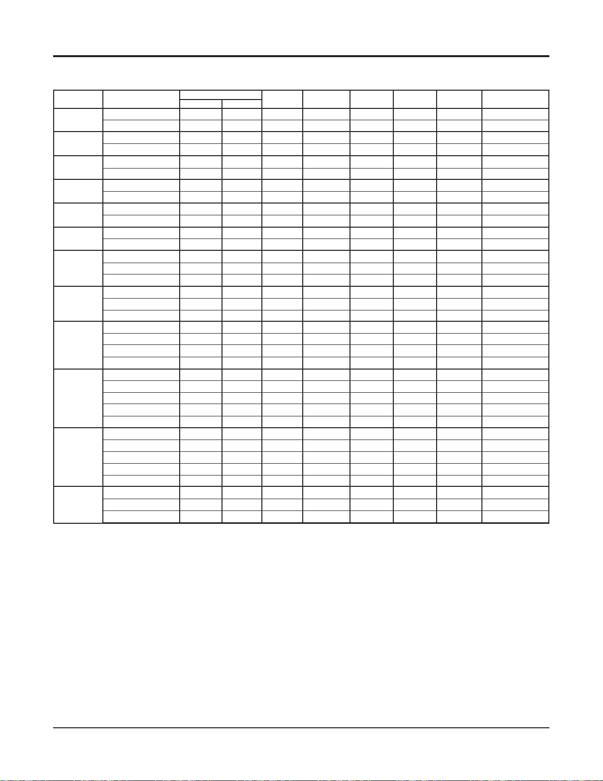
Electrical Data – VFC, VFW 007 - 070
Unit With Desuperheater
Unit Size
007
009
012
015
019
024
Voltage/Hz/Phase
208/230-60-1
265-60-1
208/230-60-1
265-60-1
208/230-60-1
265-60-1
208/230-60-1
265-60-1
208/230-60-1
265-60-1
208/230-60-1
265-60-1
208/230-60-1
030
265-60-1
208/230-60-3
208/230-60-1
036
208/230-60-3
460-60-3
042
208/230-60-1
208/230-60-3
460-60-3
575-60-3
208/230-60-1
208/230-60-3
048
265-60-1
460-60-3
575-60-3
208/230-60-1
208/230-60-3
060
265-60-1
460-60-3
575-60-3
070
n/a = Desuperheater option not available for unit sizes 007, 009, 012 & 015.
208/230-60-3
460-60-3
575-60-3
Compressor
RLA
n/a
n/a
n/a
n/a
n/a
n/a
n/a
n/a
9.0
-
13.5
-
14.1
-
8.9
17.9
13.2
-
19.9
13.6
-
-
21.8
13.7
-
-
-
26.3
15.6
-
-
-
22.4
-
-
LRA
n/a
n/a
n/a
n/a
n/a
n/a
n/a
n/a
48.0
58.3
73.0
58.0
112.0
88.0
109.0
83.1
117.0
83.1
134.0
110.0
149.0
Desuperheater Total Unit
PSC Fan
Motor FLA Pump FLA FLA Amps
n/a
n/a
n/a
n/a
n/a
n/a
n/a
n/a
1.20
-
-
1.20
-
-
3.50
-
-
3.50
3.50
3.50
-
-
4.29
4.29
-
-
-
-
4.29
4.29
-
-
-
-
-
-
4.29
4.29
-
-
-
-
-
-
4.29
-
-
-
-
n/a
n/a
n/a
n/a
n/a
n/a
n/a
n/a
0.40
-
0.40
-
0.40
-
0.40
0.40
0.40
-
0.40
0.40
-
-
0.40
0.40
-
-
-
0.40
0.40
-
-
-
0.40
-
-
n/a
n/a
n/a
n/a
n/a
n/a
n/a
n/a
10.6
-
15.1
-
18.0
-
12.8
21.8
17.1
-
24.6
18.3
-
-
26.5
18.4
-
-
-
31.0
20.3
-
-
-
27.1
-
-
Min. Voltage
n/a
n/a
n/a
n/a
n/a
n/a
n/a
n/a
197
-
197
-
197
-
197
197
197
-
197
197
-
-
197
197
-
-
-
197
197
-
-
-
197
-
-
Min. Circuit Max. Fuse or
HACR Breaker Size
n/a
n/a
n/a
n/a
n/a
n/a
n/a
n/a
12.8
-
18.4
-
21.5
-
15.0
26.3
20.4
-
29.5
21.7
-
-
31.9
21.8
-
-
-
37.5
24.2
-
-
-
32.7
-
-
n/a
n/a
n/a
n/a
n/a
n/a
n/a
n/a
20.0
-
30.0
-
35.0
-
20.0
40.0
30.0
-
45.0
35.0
-
-
50.0
35.0
-
-
-
60.0
35.0
-
-
-
50.0
-
-
Catalog 1103-2 McQuay Ennity Water Source Heat Pumps 49
Page 50

Electrical Data – VFC, VFW 007 - 070
Unit With ECM
Unit Size Voltage/Hz/Phase
007
009
012
015
019
024
030
036
208/230-60-1
265-60-1
208/230-60-1
265-60-1
208/230-60-1
265-60-1
208/230-60-1
265-60-1
208/230-60-1
265-60-1
208/230-60-1
265-60-1
208/230-60-1
265-60-1
208/230-60-3
208/230-60-1
208/230-60-3
460-60-3
042
208/230-60-1
208/230-60-3
460-60-3
575-60-3
048
060
070
* Not available at time of publication. Please consult your McQuay Representative for specific availability
n/a = ECM not available in unit sizes 007, 009, 012.
208/230-60-1
208/230-60-3
265-60-1
460-60-3
575-60-3
208/230-60-1
208/230-60-3
265-60-1
460-60-3
575-60-3
208/230-60-3
460-60-3
575-60-3
Compressor
RLA
n/a
n/a
n/a
n/a
n/a
n/a
*
*
9.0
7.1
13.5
9.0
14.1
11.2
8.9
17.9
13.2
6.0
19.9
13.6
6.1
-
21.8
13.7
16.3
6.2
-
26.3
15.6
19.9
7.8
-
22.4
10.6
-
LRA
n/a
n/a
n/a
n/a
n/a
n/a
48.0
43.0
58.3
54.0
73.0
60.0
58.0
112.0
88.0
44.0
109.0
83.1
41.0
117.0
83.1
98.0
41.0
134.0
110.0
128.0
52.0
149.0
75.0
Total Unit
ECM Fan
Motor FLA FLA Amps HACR Breaker Sizen/
n/a
n/a
n/a
n/a
n/a
n/a
*
*
*
*
2.80
2.40
2.80
2.40
4.30
4.10
4.30
4.30
4.30
4.10
6.80
6.80
5.50
-
-
6.80
6.80
5.50
5.50
-
-
9.10
9.10
6.90
6.90
-
-
9.10
6.90
-
-
n/a
n/a
n/a
n/a
n/a
n/a
11.8
9.5
16.3
11.4
18.4
15.3
13.2
22.2
17.5
10.1
26.7
20.4
11.6
28.6
20.5
21.8
11.7
35.4
24.7
26.8
14.7
31.5
17.5
Min. Voltage
*
*
-
-
-
-
n/a
n/a
n/a
n/a
n/a
n/a
*
*
197
240
197
240
197
240
197
197
197
416
197
197
416
-
197
197
240
416
-
197
197
240
416
-
197
416
-
Min. Circuit
n/a
n/a
n/a
n/a
n/a
n/a
*
*
14.0
11.2
19.6
13.6
21.9
18.1
15.4
26.7
20.8
11.6
31.6
23.8
13.1
-
34.0
23.9
25.9
13.3
-
42.0
28.7
31.7
16.6
-
37.1
20.1
-
Max. Fuse or
n/a
n/a
n/a
n/a
n/a
n/a
*
*
20.0
15.0
30.0
20.0
35.0
25.0
20.0
40.0
30.0
15.0
50.0
35.0
15.0
50.0
35.0
40.0
15.0
-
60.0
40.0
50.0
20.0
-
50.0
30.0
-
50 McQuay Ennity Water Source Heat Pumps Catalog 1103-2
Page 51
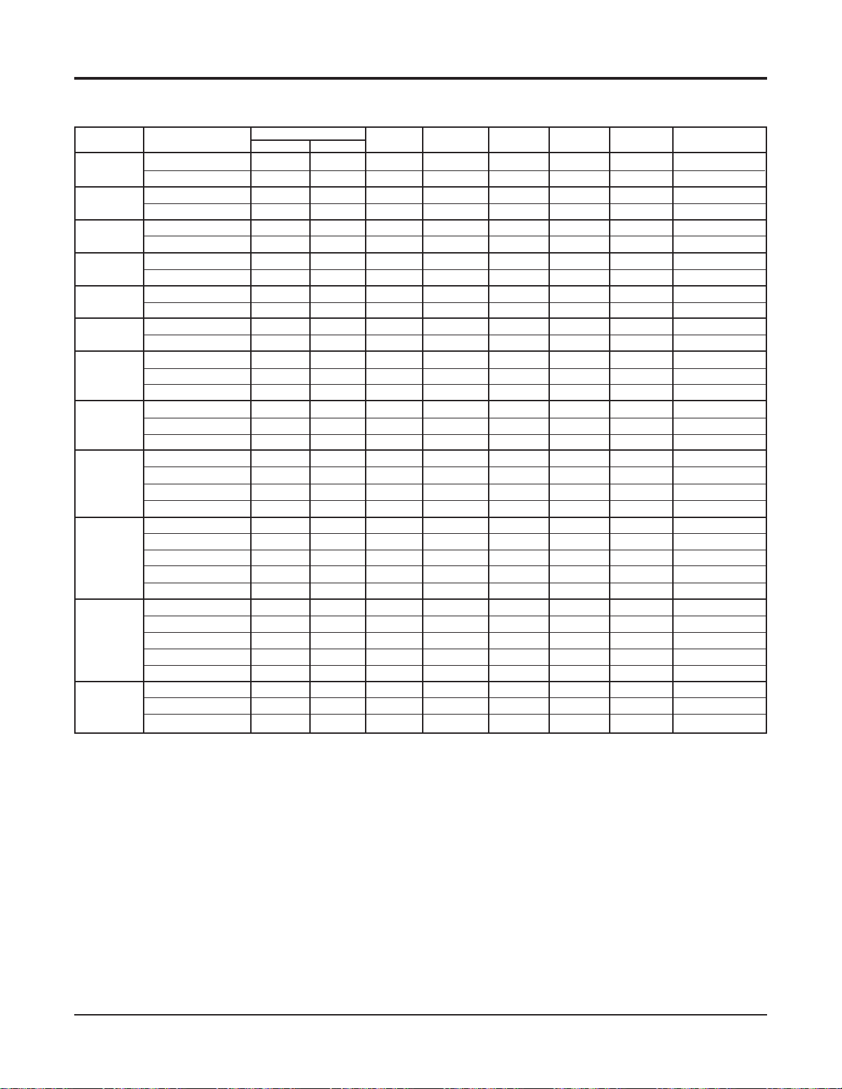
Electrical Data – VFC, VFW 007 - 070
Unit With Desuperheater and ECM
Unit Size
007
009
012
015
019
024
030
036
Voltage/Hz/Phase
208/230-60-1
265-60-1
208/230-60-1
265-60-1
208/230-60-1
265-60-1
208/230-60-1
265-60-1
208/230-60-1
265-60-1
208/230-60-1
265-60-1
208/230-60-1
265-60-1
208/230-60-3
208/230-60-1
208/230-60-3
460-60-3
042
208/230-60-1
208/230-60-3
460-60-3
575-60-3
048
208/230-60-1
208/230-60-3
265-60-1
460-60-3
575-60-3
208/230-60-1
060
070
* Not available at time of publication. Please consult your McQuay Representative for specific availability
n/a = ECM not available in unit sizes 007, 009, 012.
208/230-60-3
265-60-1
460-60-3
575-60-3
208/230-60-3
460-60-3
575-60-3
Compressor
RLA
n/a
n/a
n/a
n/a
n/a
n/a
*
*
9.0
-
13.5
-
14.1
-
8.9
17.9
13.2
-
19.9
13.6
-
-
21.8
13.7
-
-
-
26.3
15.6
-
-
-
22.4
-
-
LRA
n/a
n/a
n/a
n/a
n/a
n/a
48.0
58.3
73.0
58.0
112.0
88.0
109.0
83.1
117.0
83.1
134.0
110.0
149.0
Desuperheater Total Unit
ECM Fan
Motor FLA Pump FLA FLA Amps
n/a
n/a
n/a
n/a
n/a
n/a
*
*
*
*
2.80
-
-
2.80
-
-
4.30
-
-
4.30
4.30
4.30
-
-
6.80
6.80
-
-
-
-
6.80
6.80
-
-
-
-
-
-
9.10
9.10
-
-
-
-
-
-
9.10
-
-
-
-
n/a
n/a
n/a
n/a
n/a
n/a
*
*
0.40
-
0.40
-
0.40
0.40
0.40
0.40
-
0.40
0.40
-
-
0.40
0.40
-
-
-
0.40
0.40
-
-
-
0.40
-
-
n/a
n/a
n/a
n/a
n/a
n/a
*
*
12.2
-
16.7
-
18.8
-
13.6
22.6
17.9
-
27.1
20.8
-
-
29.0
20.9
-
-
-
35.8
25.1
-
-
-
31.9
-
-
Min. Voltage
n/a
n/a
n/a
n/a
n/a
n/a
*
*
197
-
197
-
197
-
197
197
197
-
197
197
-
-
197
197
-
-
-
197
197
-
-
-
197
-
-
Min. Circuit Max. Fuse or
HACR Breaker Size
n/a
n/a
n/a
n/a
n/a
n/a
*
*
14.4
-
20.0
-
22.3
-
15.8
27.1
21.2
-
32.0
24.2
-
-
34.4
24.3
-
-
-
42.4
29.1
-
-
-
37.5
-
-
n/a
n/a
n/a
n/a
n/a
n/a
*
*
20.0
-
30.0
-
35.0
-
20.0
45.0
30.0
-
50.0
35.0
-
-
50.0
35.0
-
-
-
60.0
40.0
-
-
-
50.0
-
-
Catalog 1103-2 McQuay Ennity Water Source Heat Pumps 51
Page 52

Electrical Data – VFC, VFW 007 - 070
Unit with 10kW Electric Heat Coil
Unit Size
007
009
012
015
019
024
030
036
Voltage/Hz/Phase
208/230-60-1
265-60-1
208/230-60-1
265-60-1
208/230-60-1
265-60-1
208/230-60-1
265-60-1
208/230-60-1
265-60-1
208/230-60-1
265-60-1
208/230-60-1
265-60-1
208/230-60-3
208/230-60-1
208/230-60-3
460-60-3
042
208/230-60-1
208/230-60-3
460-60-3
575-60-3
048
208/230-60-1
208/230-60-3
265-60-1
460-60-3
060
070
575-60-3
208/230-60-1
208/230-60-3
265-60-1
460-60-3
575-60-3
208/230-60-3
460-60-3
575-60-3
Compressor
RLA
n/a
n/a
n/a
n/a
n/a
n/a
n/a
n/a
9.0
7.1
13.5
9.0
14.1
11.2
8.9
17.9
13.2
6.0
19.9
13.6
6.1
4.2
21.8
13.7
-
6.2
4.8
26.3
15.6
-
7.8
5.8
22.4
10.6
7.7
LRA
n/a
n/a
n/a
n/a
n/a
n/a
n/a
n/a
48.0
43.0
58.3
54.0
73.0
60.0
58.0
112.0
88.0
44.0
109.0
83.1
41.0
33.0
117.0
83.1
41.0
33.0
134.0
110.0
52.0
38.9
149.0
75.0
54.0
Electric Heater Total Unit
PSC Fan
Motor FLA RLA FLA Amps
n/a
n/a
n/a
n/a
n/a
n/a
n/a
n/a
1.20
0.90
1.20
0.90
3.50
2.80
3.50
3.50
3.50
1.60
4.29
4.29
1.60
1.30
4.29
4.29
-
-
1.60
1.30
4.29
4.29
-
-
1.60
1.30
4.29
1.60
1.30
n/a
n/a
n/a
n/a
n/a
n/a
n/a
n/a
40.0
34.7
40.0
34.7
40.0
34.7
23.1
40.0
23.1
11.6
41.7
24.1
12.0
9.6
41.7
24.1
-
12.0
9.6
41.7
24.1
-
12.0
9.6
24.1
12.0
9.6
n/a
n/a
n/a
n/a
n/a
n/a
n/a
n/a
50.2
42.7
54.7
44.6
57.6
48.7
35.5
61.4
39.8
19.2
65.9
42.0
18.1
13.8
67.8
42.1
-
18.2
14.4
72.3
44.0
-
19.8
15.4
50.8
22.6
17.3
Min. Voltage
n/a
n/a
n/a
n/a
n/a
n/a
n/a
n/a
197
240
197
240
197
240
197
197
197
416
197
197
416
520
197
197
-
416
520
197
197
-
416
520
197
416
520
Min. Circuit Max. Fuse or
HACR Breaker Size
n/a
n/a
n/a
n/a
n/a
n/a
n/a
n/a
62.4
53.1
68.0
55.5
71.1
60.2
43.5
75.9
48.9
23.6
81.3
51.4
22.6
17.2
83.7
51.6
-
22.8
18.0
89.3
54.0
-
24.7
19.3
62.5
28.2
21.6
n/a
n/a
n/a
n/a
n/a
n/a
n/a
n/a
60.0
50.0
70.0
50.0
70.0
60.0
45.0
80.0
50.0
25.0
90.0
50.0
25.0
15.0
90.0
50.0
-
25.0
20.0
100.0
60.0
-
25.0
20.0
70.0
35.0
25.0
n/a = Electric Heat not available in unit sizes 007, 009, 012, 015.
52 McQuay Ennity Water Source Heat Pumps Catalog 1103-2
Page 53
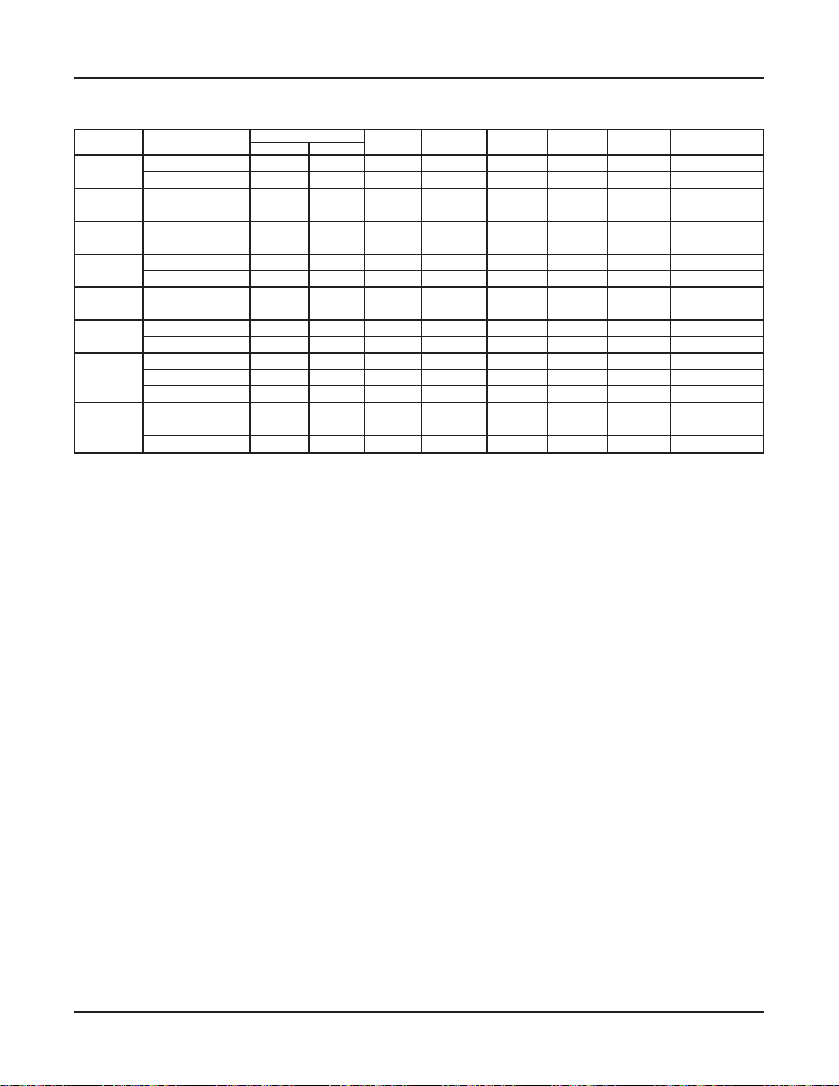
Electrical Data – VFC, VFW 007 - 070
Unit with 5kW Electric Heat Coil
Unit Size
*007
009
012
015
019
024
030
036
Voltage/Hz/Phase
208/230-60-1
265-60-1
208/230-60-1
265-60-1
208/230-60-1
265-60-1
208/230-60-1
265-60-1
208/230-60-1
265-60-1
208/230-60-1
265-60-1
208/230-60-1
265-60-1
208/230-60-3
208/230-60-1
208/230-60-3
460-60-3
Compressor
RLA
n/a
n/a
n/a
n/a
n/a
n/a
n/a
n/a
9.0
7.1
13.5
9.0
14.1
11.2
8.9
17.9
13.2
-
LRA
n/a
n/a
n/a
n/a
n/a
n/a
n/a
n/a
48.0
43.0
58.3
54.0
73.0
60.0
58.0
112.0
88.0
Electric Heater Total Unit
PSC Fan
Motor FLA RLA FLA Amps
n/a
n/a
n/a
n/a
n/a
n/a
n/a
n/a
1.20
0.90
1.20
0.90
3.50
2.80
3.50
3.50
3.50
-
-
n/a
n/a
n/a
n/a
n/a
n/a
n/a
n/a
22.5
19.5
22.5
19.5
22.5
19.5
22.5
22.5
22.5
-
n/a
n/a
n/a
n/a
n/a
n/a
n/a
n/a
32.7
27.5
37.2
29.4
40.1
33.5
34.9
43.9
39.2
-
Min. Voltage
n/a
n/a
n/a
n/a
n/a
n/a
n/a
n/a
197
240
197
240
197
240
197
197
197
-
Min. Circuit Max. Fuse or
HACR Breaker Size
n/a
n/a
n/a
n/a
n/a
n/a
n/a
n/a
40.5
34.1
46.2
36.5
49.3
41.2
42.8
54.1
48.1
-
n/a
n/a
n/a
n/a
n/a
n/a
n/a
n/a
40.0
35.0
50.0
40.0
50.0
45.0
45.0
60.0
50.0
-
n/a = Electric Heat not available in unit sizes 007, 009, 012, 015.
Catalog 1103-2 McQuay Ennity Water Source Heat Pumps 53
Page 54
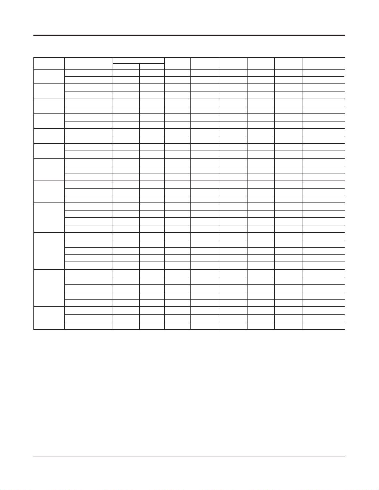
Electrical Data – VFC, VFW 007 - 070
Unit with ECM and 10kW Electric Heat Coil
Unit Size
007
009
012
015
019
024
030
036
Voltage/Hz/Phase
208/230-60-1
265-60-1
208/230-60-1
265-60-1
208/230-60-1
265-60-1
208/230-60-1
265-60-1
208/230-60-1
265-60-1
208/230-60-1
265-60-1
208/230-60-1
265-60-1
208/230-60-3
208/230-60-1
208/230-60-3
460-60-3
042
208/230-60-1
208/230-60-3
460-60-3
575-60-3
208/230-60-1
048
208/230-60-3
265-60-1
460-60-3
575-60-3
208/230-60-1
060
070
208/230-60-3
265-60-1
460-60-3
575-60-3
208/230-60-3
460-60-3
575-60-3
Compressor
RLA
n/a
n/a
n/a
n/a
n/a
n/a
n/a
n/a
9.0
7.1
13.5
9.0
14.1
11.2
8.9
17.9
13.2
6.0
19.9
13.6
6.1
-
21.8
13.7
-
6.2
-
26.3
15.6
-
7.8
-
22.4
10.6
-
LRA
n/a
n/a
n/a
n/a
n/a
n/a
n/a
n/a
48.0
43.0
58.3
54.0
73.0
60.0
58.0
112.0
88.0
44.0
109.0
83.1
41.0
117.0
83.1
41.0
134.0
110.0
52.0
149.0
75.0
Electric Heater Total Unit
ECM Fan
Motor FLA RLA FLA Amps
n/a
n/a
n/a
n/a
n/a
n/a
n/a
n/a
2.80
2.40
2.80
2.40
4.30
4.10
4.30
4.30
4.30
4.10
6.80
6.80
5.50
-
-
6.80
6.80
-
-
5.50
-
-
9.10
9.10
-
-
6.90
-
-
9.10
6.90
-
-
n/a
n/a
n/a
n/a
n/a
n/a
n/a
n/a
40.0
34.7
40.0
34.7
40.0
34.7
23.1
40.0
23.1
11.6
41.7
24.1
12.0
-
41.7
24.1
-
12.0
-
41.7
24.1
-
12.0
-
24.1
12.0
-
n/a
n/a
n/a
n/a
n/a
n/a
n/a
n/a
51.8
44.2
56.3
46.1
58.4
50.0
36.3
62.2
40.6
21.7
68.4
44.5
23.6
-
70.3
44.6
-
23.7
-
77.1
48.8
-
26.7
-
55.6
29.5
-
Min. Voltage
n/a
n/a
n/a
n/a
n/a
n/a
n/a
n/a
197
240
197
240
197
197
240
197
197
416
197
197
416
-
197
197
-
416
-
197
197
-
416
-
197
416
-
Min. Circuit Max. Fuse or
HACR Breaker Size
n/a
n/a
n/a
n/a
n/a
n/a
n/a
n/a
64.0
54.6
69.6
57.0
71.9
61.5
44.3
76.7
49.7
26.1
83.8
53.9
28.1
-
86.2
54.1
-
28.3
-
94.1
58.8
-
31.6
-
67.3
35.1
-
n/a
n/a
n/a
n/a
n/a
n/a
n/a
n/a
60.0
50.0
70.0
50.0
70.0
60.0
45.0
80.0
50.0
25.0
90.0
60.0
30.0
-
90.0
60.0
-
30.0
-
100.0
60.0
-
35.0
-
80.0
40.0
-
n/a = Electric Heat not available in unit sizes 007, 009, 012, 015.
54 McQuay Ennity Water Source Heat Pumps Catalog 1103-2
Page 55

Electrical Data – VFC, VFW 007 - 070
Unit with ECM and 5kW Electric Heat Coil
Unit Size
007
009
012
015
019
024
030
036
Voltage/Hz/Phase
208/230-60-1
265-60-1
208/230-60-1
265-60-1
208/230-60-1
265-60-1
208/230-60-1
265-60-1
208/230-60-1
265-60-1
208/230-60-1
265-60-1
208/230-60-1
265-60-1
208/230-60-3
208/230-60-1
208/230-60-3
460-60-3
Compressor
RLA
n/a
n/a
n/a
n/a
n/a
n/a
n/a
n/a
9.0
7.1
13.5
9.0
14.1
11.2
8.9
17.9
13.2
-
LRA
n/a
n/a
n/a
n/a
n/a
n/a
n/a
n/a
48.0
43.0
58.3
54.0
73.0
60.0
58.0
112.0
88.0
Electric Heater Total Unit
ECM Fan
Motor FLA RLA FLA Amps
n/a
n/a
n/a
n/a
n/a
n/a
n/a
n/a
2.80
2.40
2.80
2.40
4.30
4.10
4.30
4.30
4.30
-
-
n/a
n/a
n/a
n/a
n/a
n/a
n/a
n/a
22.5
19.5
22.5
19.5
22.5
19.5
22.5
22.5
22.5
-
n/a
n/a
n/a
n/a
n/a
n/a
n/a
n/a
34.3
29.0
38.8
30.9
40.9
34.8
35.7
44.7
40.0
-
Min. Voltage
n/a
n/a
n/a
n/a
n/a
n/a
n/a
n/a
197
240
197
240
197
240
197
197
197
-
Min. Circuit Max. Fuse or
HACR Breaker Size
n/a
n/a
n/a
n/a
n/a
n/a
n/a
n/a
42.1
35.6
47.8
38.0
50.1
42.5
43.6
54.9
48.9
-
n/a
n/a
n/a
n/a
n/a
n/a
n/a
n/a
45.0
35.0
50.0
40.0
50.0
45.0
45.0
60.0
50.0
-
n/a = Electric Heat not available in unit sizes 007, 009, 012, 015.
Catalog 1103-2 McQuay Ennity Water Source Heat Pumps 55
Page 56

Electrical Data – VFC, VFW 007 - 070
Unit with Desuperheater and 10kW Electric Heat Coil
Unit Size
007
009
012
015
019
024
030
036
208/230-60-1
208/230-60-1
208/230-60-1
208/230-60-1
208/230-60-1
208/230-60-1
208/230-60-1
208/230-60-3
208/230-60-1
208/230-60-3
Voltage/Hz/Phase
265-60-1
265-60-1
265-60-1
265-60-1
265-60-1
265-60-1
265-60-1
460-60-3
042
208/230-60-1
208/230-60-3
460-60-3
575-60-3
208/230-60-1
048
208/230-60-3
265-60-1
460-60-3
575-60-3
208/230-60-1
060
070
n/a = Electric Heat not available in unit sizes 007, 009, 012, 015.
208/230-60-3
265-60-1
460-60-3
575-60-3
208/230-60-3
460-60-3
575-60-3
Compressor
RLA
n/a
n/a
n/a
n/a
n/a
n/a
n/a
n/a
9.0
-
13.5
-
14.1
-
8.9
17.9
13.2
-
19.9
13.6
-
-
21.8
13.7
-
-
-
26.3
15.6
-
-
-
22.4
-
-
LRA
n/a
n/a
n/a
n/a
n/a
n/a
n/a
n/a
48.0
58.3
73.0
58.0
112.0
88.0
109.0
83.1
117.0
83.1
134.0
110.0
149.0
Desuperheater Electric Total Unit
PSC Fan
Motor FLA Pump FLA Heater RLA FLA
n/a
n/a
n/a
n/a
n/a
n/a
n/a
n/a
1.2
-
-
1.2
-
-
3.5
-
-
3.5
3.5
3.5
-
-
4.29
4.29
-
-
-
-
4.29
4.29
-
-
-
-
-
-
4.29
4.29
-
-
-
-
-
-
4.29
-
-
-
-
n/a
n/a
n/a
n/a
n/a
n/a
n/a
n/a
0.4
-
0.4
-
0.4
-
0.4
0.4
0.4
-
0.4
0.4
-
-
0.4
0.4
-
-
-
0.4
0.4
-
-
-
0.4
-
-
n/a
n/a
n/a
n/a
n/a
n/a
n/a
n/a
40.0
-
40.0
-
40.0
-
23.1
40.0
23.1
-
41.7
24.1
-
-
41.7
24.1
-
-
-
41.7
24.1
-
-
-
24.1
-
-
n/a
n/a
n/a
n/a
n/a
n/a
n/a
n/a
50.6
-
55.1
-
58.0
-
35.9
61.8
40.2
-
66.3
42.4
-
-
68.2
42.5
-
-
-
72.7
44.4
-
-
-
51.2
-
-
Min. Voltage
n/a
n/a
n/a
n/a
n/a
n/a
n/a
n/a
197
197
197
197
197
197
197
197
197
197
197
197
197
Min. Circuit Max. Fuse or
Amps HACR Breaker Size
n/a
n/a
n/a
n/a
n/a
n/a
n/a
n/a
62.8
-
-
68.4
-
-
71.5
-
-
43.9
76.3
49.3
-
-
81.7
51.8
-
-
-
-
84.1
52.0
-
-
-
-
-
-
89.7
54.4
-
-
-
-
-
-
62.9
-
-
-
-
n/a
n/a
n/a
n/a
n/a
n/a
n/a
n/a
60.0
-
70.0
-
70.0
-
45.0
80.0
50.0
-
90.0
50.0
-
-
90.0
50.0
-
-
-
100.0
60.0
-
-
-
70.0
-
-
56 McQuay Ennity Water Source Heat Pumps Catalog 1103-2
Page 57
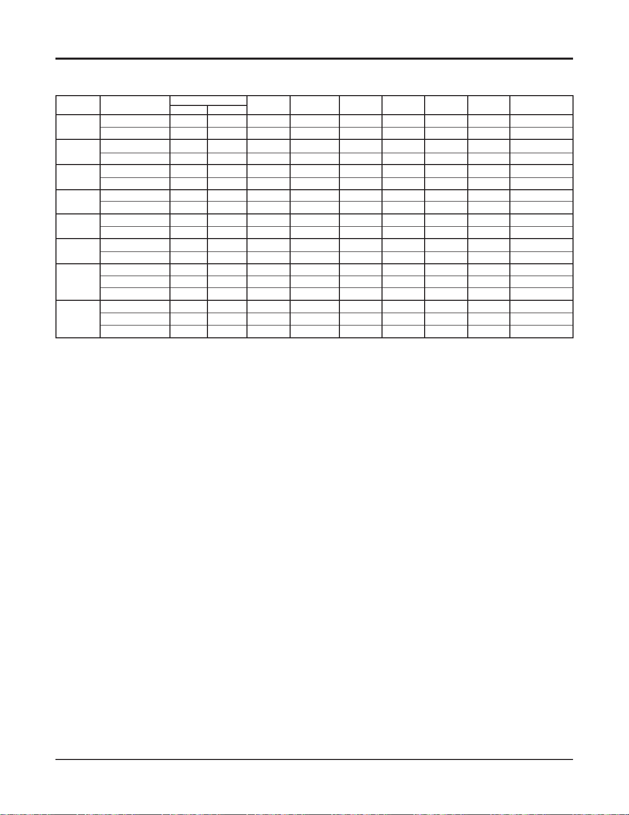
Electrical Data – VFC, VFW 007 - 070
Unit with Desuperheater and 5kW Electric Heat Coil
Unit Size Voltage/Hz/Phase
007
009
012
015
019
024
030
208/230-60-1
265-60-1
208/230-60-1
265-60-1
208/230-60-1
265-60-1
208/230-60-1
265-60-1
208/230-60-1
265-60-1
208/230-60-1
265-60-1
208/230-60-1
265-60-1
208/230-60-3
036
n/a = Electric Heat not available in unit sizes 007, 009, 012, 015.
208/230-60-1
208/230-60-3
460-60-3
Compressor
RLA
n/a
n/a
n/a
n/a
n/a
n/a
n/a
n/a
9.0
-
13.5
-
14.1
-
8.9
17.9
13.2
-
LRA
n/a
n/a
n/a
n/a
n/a
n/a
n/a
n/a
48.0
-
58.3
-
73.0
-
58.0
112.0
88.0
-
Desuperheater Electric Total Unit
PSC Fan
Motor FLA Pump FLA Heater RLA FLA
n/a
n/a
n/a
n/a
n/a
n/a
n/a
n/a
1.20
-
1.20
-
3.50
-
3.50
3.50
3.50
-
n/a
n/a
n/a
n/a
n/a
n/a
n/a
n/a
0.4
-
0.4
-
0.4
-
0.4
0.4
0.4
-
n/a
n/a
n/a
n/a
n/a
n/a
n/a
n/a
22.5
-
22.5
-
22.5
-
22.5
22.5
22.5
-
n/a
n/a
n/a
n/a
n/a
n/a
n/a
n/a
33.1
-
37.6
-
40.5
-
35.3
44.3
39.6
-
Min. Voltage
n/a
n/a
n/a
n/a
n/a
n/a
n/a
n/a
197
197
197
197
197
197
Min. Circuit Max. Fuse or
Amps HACR Breaker Size
n/a
n/a
n/a
n/a
n/a
n/a
n/a
n/a
40.9
-
-
46.6
-
-
49.7
-
-
43.2
54.5
48.5
-
-
n/a
n/a
n/a
n/a
n/a
n/a
n/a
n/a
40.0
-
50.0
-
50.0
-
45.0
60.0
50.0
-
Catalog 1103-2 McQuay Ennity Water Source Heat Pumps 57
Page 58

Electrical Data – VFC, VFW 007 - 070
Unit with Desuperheater, ECM and 10kW Electric Heat Coil
Unit Size Voltage/Hz/Phase
007
009
012
015
019
024
030
036
208/230-60-1
265-60-1
208/230-60-1
265-60-1
208/230-60-1
265-60-1
208/230-60-1
265-60-1
208/230-60-1
265-60-1
208/230-60-1
265-60-1
208/230-60-1
265-60-1
208/230-60-3
208/230-60-1
208/230-60-3
460-60-3
042
208/230-60-1
208/230-60-3
460-60-3
575-60-3
048
208/230-60-1
208/230-60-3
265-60-1
460-60-3
575-60-3
208/230-60-1
060
070
n/a = Electric Heat not available in unit sizes 007, 009, 012, 015.
208/230-60-3
265-60-1
460-60-3
575-60-3
208/230-60-3
460-60-3
575-60-3
Compressor
RLA
n/a
n/a
n/a
n/a
n/a
n/a
n/a
n/a
9.0
-
13.5
-
14.1
-
8.9
17.9
13.2
-
19.9
13.6
-
-
21.8
13.7
-
-
-
26.3
15.6
-
-
-
22.4
-
-
LRA
n/a
n/a
n/a
n/a
n/a
n/a
n/a
n/a
48.0
-
58.3
-
73.0
-
58.0
112.0
88.0
-
109.0
83.1
-
-
117.0
83.1
-
-
-
134.0
110.0
-
-
-
149.0
-
-
Desuperheater Electric Total Unit
ECM Fan
Motor FLA Pump FLA Heater RLA FLA
n/a
n/a
n/a
n/a
n/a
n/a
n/a
n/a
2.80
-
2.80
-
4.30
-
4.30
4.30
4.30
-
6.80
6.80
-
-
6.80
6.80
-
-
-
9.10
9.10
-
-
-
9.10
-
-
n/a
n/a
n/a
n/a
n/a
n/a
n/a
n/a
0.4
-
0.4
-
0.4
-
0.4
0.4
0.4
-
0.4
0.4
-
-
0.4
0.4
-
-
-
0.4
0.4
-
-
-
0.4
-
-
n/a
n/a
n/a
n/a
n/a
n/a
n/a
n/a
40.0
-
40.0
-
40.0
-
23.1
40.0
23.1
-
41.7
24.1
-
-
41.7
24.1
-
-
-
41.7
24.1
-
-
-
24.1
-
-
n/a
n/a
n/a
n/a
n/a
n/a
n/a
n/a
52.2
-
56.7
-
58.8
-
36.7
62.6
41.0
-
68.8
44.9
-
-
70.7
45.0
-
-
-
77.5
49.2
-
-
-
56.0
-
-
Min. Voltage
n/a
n/a
n/a
n/a
n/a
n/a
n/a
n/a
197
197
197
197
197
197
197
197
197
197
197
197
197
Min. Circuit Max. Fuse or
Amps HACR Breaker Size
n/a
n/a
n/a
n/a
n/a
n/a
n/a
n/a
64.4
-
-
70.0
-
-
72.3
-
-
44.7
77.1
50.1
-
-
84.2
54.3
-
-
-
-
86.6
54.5
-
-
-
-
-
-
94.5
59.2
-
-
-
-
-
-
67.7
-
-
-
-
n/a
n/a
n/a
n/a
n/a
n/a
n/a
n/a
60.0
-
70.0
-
70.0
-
45.0
80.0
50.0
-
90.0
60.0
-
-
90.0
60.0
-
-
-
110.3
60.0
-
-
-
80.0
-
-
58 McQuay Ennity Water Source Heat Pumps Catalog 1103-2
Page 59

Electrical Data – VFC, VFW 007 - 070
Unit with Desuperheater, ECM and 5kW Electric Heat Coil
Unit Size Voltage/Hz/Phase
007
009
012
015
019
024
030
036
208/230-60-1
265-60-1
208/230-60-1
265-60-1
208/230-60-1
265-60-1
208/230-60-1
265-60-1
208/230-60-1
265-60-1
208/230-60-1
265-60-1
208/230-60-1
265-60-1
208/230-60-3
208/230-60-1
208/230-60-3
460-60-3
n/a = Electric Heat not available in unit sizes 007, 009, 012, 015.
Compressor
RLA
n/a
n/a
n/a
n/a
n/a
n/a
n/a
n/a
9.0
-
13.5
-
14.1
-
8.9
17.9
13.2
-
LRA
n/a
n/a
n/a
n/a
n/a
n/a
n/a
n/a
48.0
58.3
73.0
58.0
112.0
88.0
Desuperheater Electric Total Unit
ECM Fan
Motor FLA Pump FLA Heater RLA FLA
n/a
n/a
n/a
n/a
n/a
n/a
n/a
n/a
2.80
-
-
2.80
-
-
4.30
-
-
4.30
4.30
4.30
-
-
n/a
n/a
n/a
n/a
n/a
n/a
n/a
n/a
0.4
-
0.4
-
0.4
-
0.4
0.4
0.4
-
n/a
n/a
n/a
n/a
n/a
n/a
n/a
n/a
22.5
-
22.5
-
22.5
-
22.5
22.5
22.5
-
n/a
n/a
n/a
n/a
n/a
n/a
n/a
n/a
34.7
-
39.2
-
41.3
-
36.1
45.1
40.4
-
Min. Voltage
n/a
n/a
n/a
n/a
n/a
n/a
n/a
n/a
197
197
197
197
197
197
Min. Circuit Max. Fuse or
Amps HACR Breaker Size
n/a
n/a
n/a
n/a
n/a
n/a
n/a
n/a
42.5
-
-
48.2
-
-
50.5
-
-
44.0
55.3
49.3
-
-
n/a
n/a
n/a
n/a
n/a
n/a
n/a
n/a
45.0
-
50.0
-
50.0
-
45.0
60.0
50.0
-
Catalog 1103-2 McQuay Ennity Water Source Heat Pumps 59
Page 60

Fan Performance
PSC Motor CFM - Sizes 007 - 070
Speed Nominal
Unit Size
009
High
007
Low
High
Low
High
2
01
Low
High
5
01
Low
High
019
Low
High
24
0
Low
High
030
Low
High
0
36
Low
High Yes
42
Medium 1400 No
0
Low
High
48
Medium 1600 No
0
Low
High
060
Medium 2000
Low
High
070
Medium 2160
Low
*
300
400
500
600
800
No
1000
No
1300
No
Yes
Yes
Yes
Factory
Wired
No
Yes
No
Yes
No
Yes
No
Yes
Yes
Yes
Yes
No
No
No
No
No
No
*
*
External Static Pressure
0.10 0.15 0.20 0.25 0.30 0.35 0.40 0.45 0.50 0.55 0.60 0.65 0.70 0.75
*
*
594
604
473
482
594
604
473
482
927
957
705
724
927
957
705
724
927
957
705
724
1532
1540
927
1006
1532
1540
927
1006
2086
2119
–
–
2086
2119
–
–
2298
2303
–
–
2298
2303
–
–
*
*
*
1524
1524
2040
–
–
2040
–
–
2302
–
–
2302
–
–
582
463
582
463
902
687
902
687
902
687
853
853
–
–
–
–
–
–
*
*
*
551
568
439
452
551
568
439
452
858
880
645
667
858
880
645
667
858
880
645
667
1499
1514
800
848
1499
1514
800
848
1931
1988
–
–
1931
1988
–
–
2313
2310
–
–
2313
2310
*
*
*
*
*
*
*
*
533
513
424
407
533
513
424
407
833
804
617
582
833
804
617
582
833
804
617
582
1478
1451
763
729
1478
1451
763
729
1872
1810
–
–
–
–
–
–
–
–
–
–
1872
–
–
2304
–
–
2304
–
–
1468
1810
1468
2280
2280
*
*
*
*
491
467
389
370
491
467
389
370
767
722
540
489
767
722
540
489
767
722
540
489
1417
1375
666
627
1417
1375
–
1743
1666
1436
1403
–
–
1743
1666
1436
1403
–
–
2234
2165
–
–
–
–
2234
2165
–
–
–
–
*
*
*
*
–
–
–
–
–
–
–
440
348
440
348
665
428
665
428
665
–
1327
554
1327
–
1574
1290
–
1574
1290
–
2068
–
–
2068
–
–
412
326
412
326
596
358
596
358
596
1273
1273
1459
1177
1459
1177
1942
1554
1942
1554
*
*
*
*
–
–
–
–
–
–
–
382
301
382
301
512
–
512
–
512
–
1216
–
1216
–
1310
1080
–
1310
1080
–
1786
1431
–
1786
1431
–
349
275
349
413
413
1155
1155
1116
983
1116
983
1601
1308
1190
1601
1308
1190
*
*
*
*
315
248
315
–
-
–
–
–
–
–
–
–
–
–
–
1095
–
–
1095
–
–
864
–
–
–
–
–
–
–
1387
1163
1163
1387
–
–
ECM Motor CFM - Sizes 007 - 070
External Static Pressure
Unit Size
009
Low
*Not available at time of publication. Please consult your McQuay Representative for specific availability
n/a = ECM not available in unit sizes 007, 009, 012.
Speed Nominal
High
007
01
01
019
0
030
0
0
0
060
070
Low
High
Low
High
2
Low
High
5
Low
High
Low
High
24
Low
High
Low
High
36
Low
High
42
Low
High
48
Low
High
High
Low
600
800
1000
1300
1400
1600
2000
2160
60 McQuay Ennity Water Source Heat Pumps Catalog 1103-2
0.10 0.15 0.20 0.25 0.30 0.35 0.40 0.45 0.50 0.55 0.60 0.65 0.70 0.75
n/a
n/a
n/a
*
1000
1300
1400
1600
1120
2000
1400
2160
1500
n/a
n/a
n/a
n/a
n/a
n/a
600
450
800
560
700
910
980
n/a
n/a
n/a
n/a
n/a
n/a
600
450
800
560
700
910
980
n/a
n/a
n/a
n/a
n/a
n/a
*
*
*
*
600
450
800
560
1000
1000
700
1300
1300
910
1400
1400
980
1600
1600
1120
1120
2000
2000
1400
1400
2160
2160
1500
1500
n/a
n/a
n/a
n/a
n/a
600
450
800
560
700
910
980
n/a
n/a
n/a
n/a
n/a
*
*
*
*
600
450
800
560
1000
1000
700
1300
1300
910
1400
1400
980
1600
1600
1120
1120
2000
2000
1400
1400
2160
2160
1500
1500
n/a
n/a
n/a
n/a
n/a
600
450
800
560
700
910
980
n/a
n/a
n/a
n/a
n/a
*
*
*
*
600
450
800
560
1000
1000
700
1300
1300
910
1400
1400
980
1600
1600
1120
1120
2000
2000
1400
1400
2160
2160
1500
1500
n/a
n/a
n/a
n/a
n/a
n/a
*
*
*
*
600
450
800
560
1000
1000
700
1300
1300
910
1400
1400
980
1600
1600
1120
1120
2000
2000
1400
1400
2160
2160
1500
1500
n/a
n/a
n/a
n/a
n/a
600
450
800
560
700
910
980
n/a
n/a
n/a
n/a
n/a
*
*
*
*
600
450
800
560
1000
1000
700
1300
1300
910
1400
1400
980
1600
1600
1120
1120
2000
2000
1400
1400
2160
2160
1500
1500
n/a
n/a
n/a
n/a
n/a
n/a
n/a
n/a
n/a
n/a
n/a
n/a
600
450
800
560
700
910
980
n/a
n/a
n/a
n/a
n/a
n/a
*
*
600
450
800
560
1000
700
1300
910
1400
980
1600
1120
2000
1400
2160
1500
n/a
n/a
n/a
n/a
n/a
n/a
*
*
600
450
800
560
1000
700
1300
910
1400
980
1600
1120
2000
1400
2160
1500
n/a
n/a
n/a
n/a
n/a
n/a
*
*
*
*
600
450
800
560
1000
700
1300
910
1400
980
1600
1120
2000
1400
2160
1500
Page 61

Physical Data
Physical Data
Unit Size
Fan Wheel - D x W (In.)
Fan Motor Horsepower
Coil Face Area (Sq. Ft.)
Coil Rows
Refrigerant Charge (Oz.)
Standard Unit
Desuperheater
Hot Gas Reheat n/a n/a n/a n/a 50 52 60 63
Filter, (Qty.) Size (In.)
Water Connections, Female NPT (In.)
Condensate Connections, Female NPT (In.)
1, 2
Weight, Operating (Lbs.)
1, 2
Weight, Shipping (Lbs.)
/ Hot Gas Reheat
/ Hot Gas Reheat
*
007 009 012 015 019 024 030 036
*
*
*
*
*
6¼ x 8
1/4
2.22
3
28.5
6¼ x 8
1/4
2.22
3
29
7 x 7⅛
1/6
3.00
3
43
7 x 7⅛ 7 x 7⅛ 7 x 7⅛ 7 x 7⅛
1/6
1/6
3.00
3.00 3.50 3.50
3 3 3 3
46
44 51.5 54.5
1/2 1/2
n/a n/a n/a n/a 47 45 53 56
(2) 20W x 10H x 1D
*
*
*
*
1/2
3/4
137
153 153 227 243 / 275 245 / 277 266 / 302 269 / 305
1/2
3/4
137
(1) 20W x 24H x 1D
1/2
3/4
205
1/2
3/4
221 / 253
1/2
(2) 20W x 14H x 1D
3/4 3/4
3/4 3/4 3/4
224 / 255 244 / 280 247 / 283
Unit Size 042 048 060 070
Fan Wheel - D x W (In.)
Fan Motor Horsepower
Coil Face Area (Sq. Ft.)
Coil Rows
Refrigerant Charge (Oz.)
Standard Unit
Desuperheater
11 x 10⅝ 11 x 10⅝ 11 x 10⅝ 11 x 10⅝
1/2
1/2 1/2 1/2
6.30
6.30 6.63 6.63
3 3 3 3
68
66 86.6 102
70 67 89 102
Hot Gas Reheat 77.5 73.5 102.5 108.5
Filter, (Qty.) Size (In.)
Water Connections, Female NPT (In.)
Condensate Connections, Female NPT (In.)
1, 2
Weight, Operating (Lbs.)
1, 2
Weight, Shipping (Lbs.) / Hot Gas Reheat
Notes:
1
Add 8 lbs. to weights shown for units congured with electric heat.
2
Add 15 lbs. to weights shown for units with desuperheater.
*
Size 007 not available at time of publication. Please contact your local McQuay Representative for specic availability.
/ Hot Gas Reheat
(1) 30W x 24H x
3/4
3/4 3/4 3/4
3/4
3/4 3/4 3/4
318 / 356
321 / 361 387 / 430
1D
(2) 30W x 18H x
1D
389 / 432
340 / 378 345 / 383 412 / 452 414 / 454
n/a = Desuperheater & Hot Gas Reheat option not available for unit sizes 007, 009, 012 & 015.
Catalog 1103-2 McQuay Ennity Water Source Heat Pumps 61
Page 62

Dimensional Data – Vertical Size
*
007, 009, 012
Left Hand and Right Hand Return
Left and Right Hand Return determined by facing the water connection side of the unit. *Size 007 not available at time of publication. Please contact your local
McQuay Representative for specic availability.
Top View – Left Hand Top View – Right Hand
Overall Unit Dimensions =
22¼"D x 20"W x 37"H
Left Hand Return Filter (Side) View Right Hand Return
Condensate
Drain Connection
Water Return
Condensate
Drain
Connection
Water Return
Water Supply
Low Voltage
7/8" (22mm)
Hole
Line Voltage
7/8" (22mm) Hole
Low
Voltage
7/8"
(22mm)
Hole
Line
Voltage
7/8"
(22mm)
Hole
Water Supply
Dimensions
Unit Size A B C D E F (Left Hand) F (Right Hand) G H J K M
(565mm) (508mm) (241mm) (127mm) (162mm) (118mm) (265mm) (483mm) (41mm) (940mm) (476mm) 2
Note: Dimensions are approximate. “M” dimension includes duct ange.
22¼" 20" 9½" 5" 6⅜" 4⅝" 107/
007 – 012
" 19" 1⅝" 37" 18¾" 1
16
11
/
16
11
/
16
Filter Dimensions
Standard 1''
Unit Size O P N Quantity
(25mm) (508mm) (254mm)
1" 20" 10"
007 – 012
2
" (43mm)
" (68mm)
Optional 2''
Unit Size O P N Quantity
(51mm) (508mm) (254mm)
Note: Nominal lter thickness is 3/4" (±1/16") or 1¾" (±1/16")
2" 20" 10"
007 – 012
62 McQuay Ennity Water Source Heat Pumps Catalog 1103-2
2
Page 63

Dimensional Data – Vertical Size 015, 019, 024
Left Hand and Right Hand Return
Left and Right Hand Return determined by facing the water connection side of the unit.
Top View – Left Hand Top View – Right Hand
Overall Unit Dimensions =
24¼"D x 23"W x 46½"H
Left Hand Return Filter (Side) View Right Hand Return
Condensate
Drain Connection
Desuperheater
Water Return
Desuperheater
Water Supply
Low Voltage
7/8" (22mm)
Hole
Line Voltage
7/8" (22mm) Hole
Water Return
Low
Voltage
7/8"
(22mm)
Hole
Line
Voltage
7/8"
(22mm)
Hole
Water Supply
Condensate
Drain
Connection
Desuperheater
Water Return
Desuperheater
Water Supply
Water Return
Water Supply
Dimensions
Unit Size A B C D E F (Left Hand) F (Right Hand) G H J K M
(616mm) (584mm) (238mm) (264mm) (189mm) (265mm) (135mm) (483mm) (67mm) (1181mm) (578mm) 2
Note: Dimensions are approximate. “M” dimension includes duct ange.
24¼" 23" 9⅜" 10⅜" 77/
015 – 024
" 10
16
7
/16" 55/
" 19" 2⅝" 46½" 22¾" 1
16
11
/
" (43mm)
16
11
/
" (68mm)
16
Filter Dimensions
Standard 1''
Unit Size O P N Quantity
(25mm) (508mm) (610mm)
1" 20" 24"
015 – 024
1
Optional 2''
Unit Size O P N Quantity
(51mm) (508mm) (610mm)
Note: Nominal lter thickness is 3/4" (±1/16") or 1¾" (±1/16")
2" 20" 24"
015 – 024
Catalog 1103-2 McQuay Ennity Water Source Heat Pumps 63
1
Page 64
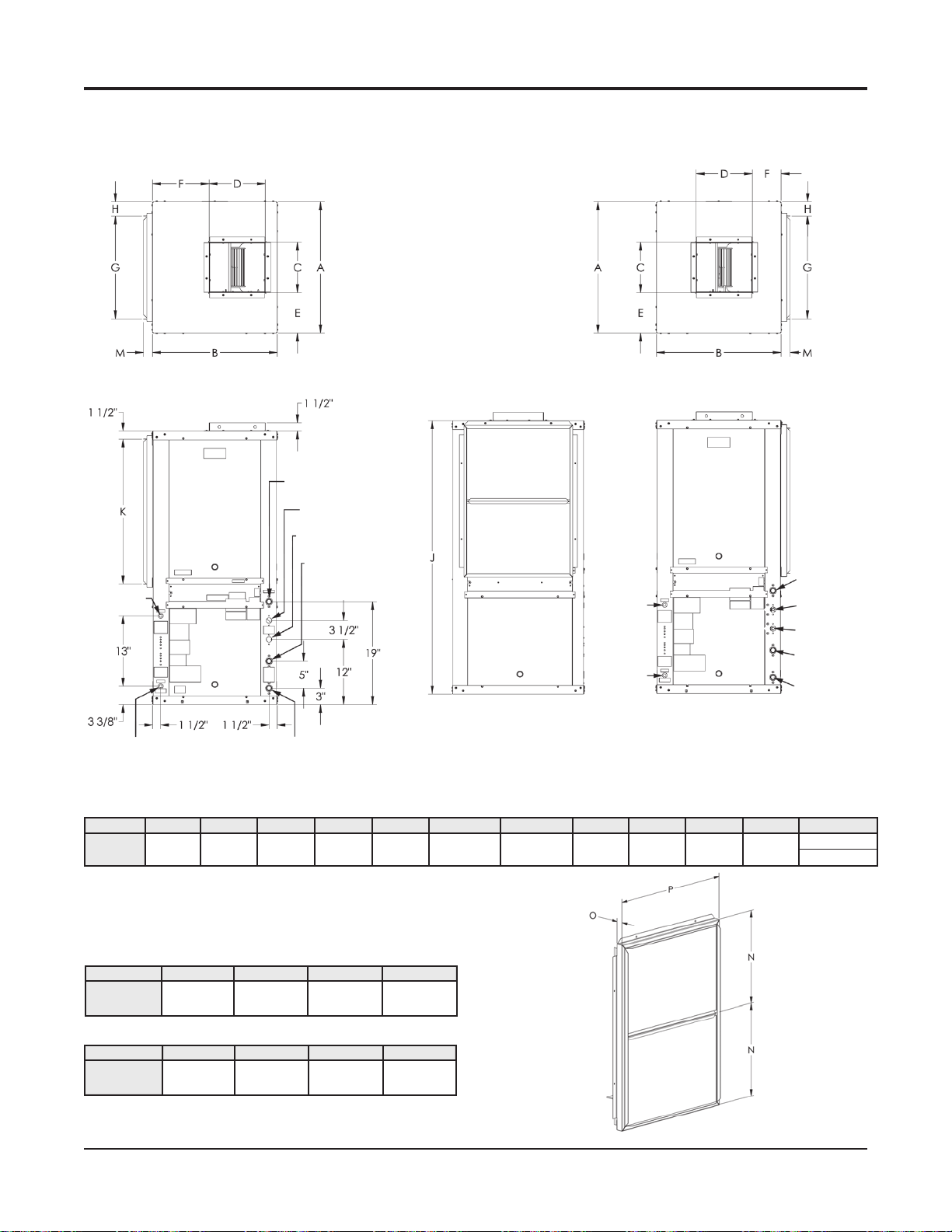
Dimensional Data – Vertical Size 030, 036
Left Hand and Right Hand Return
Left and Right Hand Return determined by facing the water connection side of the unit.
Top View – Left Hand Top View – Right Hand
Overall Unit Dimensions =
24¼"D x 23"W x 50½"H
Left Hand Return
Low Voltage
7/8" (22mm)
Hole
Line Voltage
7/8" (22mm) Hole
Filter (Side) View Right Hand Return
Condensate
Drain Connection
Desuperheater
Water Return
Desuperheater
Water Supply
Water Return
Water Supply
Low
Voltage
7/8"
(22mm)
Hole
Line
Voltage
7/8"
(22mm)
Hole
Condensate
Drain
Connection
Desuperheater
Water Return
Desuperheater
Water Supply
Water Return
Water Supply
Dimensions
Unit Size A B C D E F (Left Hand) F (Right Hand) G H J K M
(616mm) (584mm) (238mm) (264mm) (189mm) (265mm) (135mm) (483mm) (67mm) (1283mm) (680mm) 2
Note: Dimensions are approximate. “M” dimension includes duct ange.
24¼" 23" 9⅜" 10⅜" 77/
030 – 036
" 10
16
7
/16" 55/
" 19" 2⅝" 50½" 26¾" 1
16
11
/
16
11
/
16
" (43mm)
" (68mm)
Filter Dimensions
Standard 1''
Unit Size O P N Quantity
(25mm) (508mm) (356mm)
1" 20" 14"
030 – 036
2
Optional 2''
Unit Size O P N Quantity
(51mm) (508mm) (356mm)
Note: Nominal lter thickness is 3/4" (±1/16") or 1¾" (±1/16")
2" 20" 14"
030 – 036
64 McQuay Ennity Water Source Heat Pumps Catalog 1103-2
2
Page 65
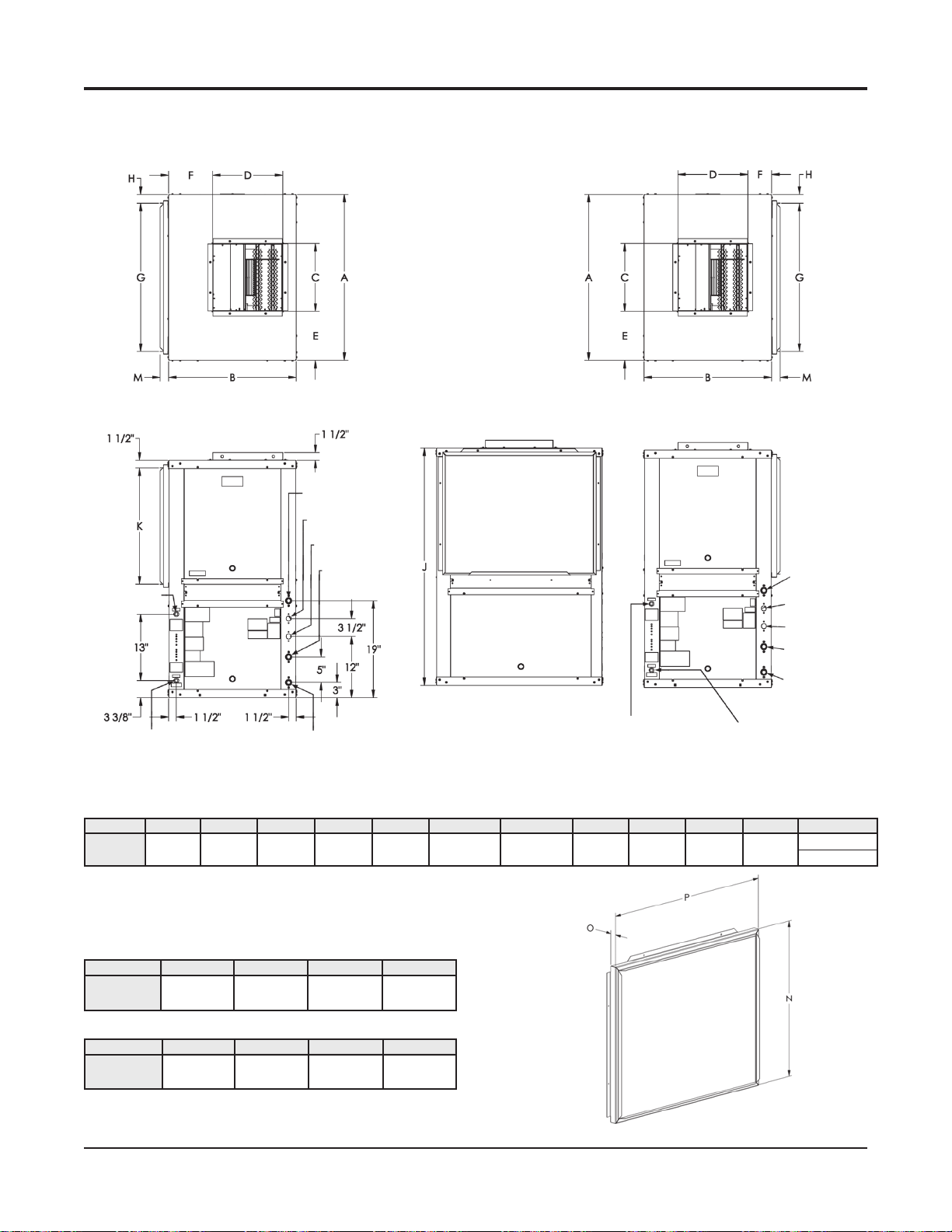
Dimensional Data – Vertical Size 042, 048
Left Hand and Right Hand Return
Left and Right Hand Return determined by facing the water connection side of the unit.
Top View – Left Hand Top View – Right Hand
Overall Unit Dimensions =
32½"D x 25"W x 46½"H
Left Hand Return Filter (Side) View Right Hand Return
Condensate
Drain Connection
Desuperheater
Water Return
Desuperheater
Water Supply
Water Return
Low Voltage
7/8" (22mm)
Hole
Condensate
Drain
Connection
Desuperheater
Water Return
Desuperheater
Water Supply
Water Return
Water Supply
Line Voltage
7/8" (22mm) Hole
Water Supply
Low Voltage
7/8" (22mm) Hole
Line Voltage
7/8" (22mm) Hole
Dimensions
Unit Size A B C D E F (Left Hand) F (Right Hand) G H J K M
(826mm) (635mm) (337mm) (349mm) (245mm) (245mm) (143mm) (737mm) (45mm) (1181mm) (578mm) 2
Note: Dimensions are approximate. “M” dimension includes duct ange.
32½" 25" 13¼" 13¾" 9⅝" 9⅝" 5⅝" 29" 1¾" 46½" 22¾" 111/
042 – 048
16
11
/
16
Filter Dimensions
Standard 1''
Unit Size O P N Quantity
(25mm) (762mm) (610mm)
1" 30" 24"
042 – 048
1
Optional 2''
Unit Size O P N Quantity
(51mm) (762mm) (610mm)
Note: Nominal lter thickness is 3/4" (±1/16") or 1¾" (±1/16")
2" 30" 24"
042 – 048
1
" (43mm)
" (68mm)
Catalog 1103-2 McQuay Ennity Water Source Heat Pumps 65
Page 66

Dimensional Data – Vertical Size 060, 070
Left Hand and Right Hand Return
Left and Right Hand Return determined by facing the water connection side of the unit.
Top View – Left Hand Top View – Right Hand
Overall Unit Dimensions =
32½"D x 25"W x 58½"H
Left Hand Return Filter (Side) View Right Hand Return
Condensate
Drain Connection
Desuperheater
Water Return
Desuperheater
Low Voltage
7/8" (22mm)
Hole
Line Voltage
7/8" (22mm) Hole
Water Supply
Water Return
Water Supply
Low Voltage
7/8" (22mm) Hole
Line Voltage
7/8" (22mm) Hole
Condensate
Drain
Connection
Desuperheater
Water Return
Desuperheater
Water Supply
Water Return
Water Supply
Dimensions
Unit Size A B C D E F (Left Hand) F (Right Hand) G H J K M
(826mm) (635mm) (337mm) (349mm) (245mm) (245mm) (143mm) (737mm) (45mm) (1486mm) (883mm) 2
Note: Dimensions are approximate. “M” dimension includes duct ange.
32½" 25" 13¼" 13¾" 9⅝" 9⅝" 5⅝" 29" 1¾" 58½" 34¾" 111/
060 – 070
16
11
/
16
Filter Dimensions
Standard 1''
Unit Size O P N Quantity
(25mm) (762mm) (457mm)
1" 30" 18"
060 – 070
2
" (43mm)
" (68mm)
Optional 2''
Unit Size O P N Quantity
(51mm) (762mm) (457mm)
Note: Nominal lter thickness is 3/4" (±1/16") or 1¾" (±1/16")
2" 30" 18"
060 – 070
66 McQuay Ennity Water Source Heat Pumps Catalog 1103-2
2
Page 67

Accessories – Field Installed
These easy-to-operate comfort command centers bring
you a complete range of deluxe features. Features that
enable you to match temperature programming to your application, provide added convenience, and help save energy
and money. All packed into an extra rugged, highly reliable
design that will look and perform like new for years to
come.
Programmable Electronic Thermostat Two-
Stage Heat/Two-Stage Cool, 7-Day Programmable
McQuay Part No. 668375301
(1-Pk, White with Wall Plate)
668375301 – Specications
Electrical Rating:
• 24 VAC (18 to 30 VAC/VDC)
• 1 amp maximum per terminal
• 4 amp maximum total load
• Easy access terminal block
Temperature Control Ranges:
• 45ºF to 90ºF (7ºC to 32ºC), Accuracy: ± 1ºF (± 0.5ºC)
System Congurations:
• Two-stage heat/Two-stage cool
Terminations:
• R, C, W1, Y1, W2, Y2, G, S1, S2
Non-Programmable, Auto or Manual Change-
over Two Stage Heat/Two Stage Cool, Night
Setback Override
McQuay Part No. 668375401
(1-Pk, White with Wall Plate)
Features
• Hardwired
• Programmable and congurable
• Simpleset
programming for the entire week
•
Title 24 compliant/No batteries required
• Relay Ouputs (minimum voltage drop in thermostat)
• Clear, backlit display makes it easy to see time,
temperature, and setpoint — even in the dark
•
Ideal l y suit e d for: Li ght com merc i al/r esid enti al
(new construction/replacement)
•
Lockout feature prevents unwanted tampering
• Optional remote temperature sensor available
(see page 68)
TM
feature enables easy copying of one day's
Features
• Hardwired
• Two-stage heat / two-stage cool systems
• Backlit display
• Field temperature calibration
• Status indicator light
• Relay outputs (minimum voltage drop in thermostat)
• Night set-back override (used when unit is wired through
a time clock on the U-terminal)
Optional remote temperature sensor available
•
(see page 68)
Catalog 1103-2 McQuay Ennity Water Source Heat Pumps 67
Page 68

Accessories – Field Installed
668375401 – Specications
Electrical Rating:
• 24 VAC (18 to 30 VAC/VDC)
• 1 amp maximum per terminal
• 4 amp maximum total load
• Easy access terminal block
Temperature Control Ranges:
• 45ºF to 90ºF (7ºC to 32ºC), Accuracy: ± 1ºF (± 0.5ºC)
System Congurations:
• Two-stage heat / two-stage cool
Timing:
• Backlight Operation: 13 seconds after mode change or
button press
Terminations:
• +R, -C, W1, Y1, W2, Y2, G, O, S1, S2
Optional Remote Sensor
Part No. 667720401 – Used with Thermostat(s)
668375301 & 668375401
The fast, easy solution for temperature sensing problems.
• For tamper prone areas
• Poor airow areas
• Troubled applications
• Foam gasket prevents drafts
through wall opening
Mounts to standard 2" x 4"
•
outlet box
•
2
3
/
"W x 4
4
1
/
"H
2
MicroTech III Water Source Heat Pump
Room Temperature Sensors
(Kit P/N 669529101, 669529201, 669529001)
Sensor 669529101
Sensor 669529201 Not Shown
Room temperature sensors provide electronic sensing of
room temperatures at wall locations. All sensor models
feature a thermistor (10kΩ), a green LED for unit
status and tenant override button. Setpoint adjustment
potentiometer, heat and fan mode switches are optional
features.
669
enant Override
T
Button
SPT
Status LED
Fan and
Mode Switches
Notes:
1
55º to 95°F (13º to 35ºC)
2
-3º to +3ºF (-1.5º to +1.5ºC)
Feature
Adj. Pot No Yes Yes
Yes Yes Yes
Sensor Kit Part Numbers
529001 669529101 669529201
Yes Yes Yes
No
MicroTech III Wall Sensor Details
Sensor 669529001
1
Yes
2
Yes
0 to 10 K ohm
Potentiometer
3.75"
Status LED
(Green)
4.59"
Mode Control
Slide Switch
68 McQuay Ennity Water Source Heat Pumps Catalog 1103-2
Tenant Override
Momentary Push Button Switch
Fan Control
Slide Switch
Page 69
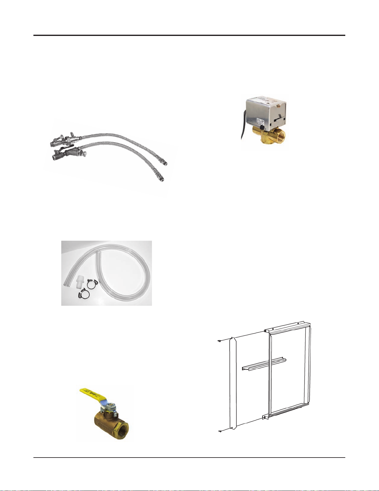
Accessories – Field Installed
Supply and Return Water Hoses
Available as re rated construction in 2 or 3 foot (610
mm or 914 mm) lengths. Fire rated hoses have a synthetic
polymer core with an outer rated covering of stainless
steel. Fittings are steel. Assembly is “re rated” and tested
according to UL 94 with a VO rating and ASTM 84. Each
hose has MPT connections. Fire rated hoses have a swivel
connection at one end. Hoses are available in 3/4" (19 mm)
to match the FPT ttings on the unit.
Flow Control, Supply and Return Water Hoses
Condensate Hose Kit
Available as a long clear plastic hose with the necessary
clamps and a MPT hose tting for connection to the FPT
eld piping.
Condensate Hose Kit
Field Installed Controls
Used for variable pumping applications, the valve is
wired in the compressor circuit and piped in the return
water line from the unit.
2-Way Motorized Valve
A motorized valve relay and control valve assembly in-
cludes a relay, valve and wire harness. The valve opens
when the compressor is on and closes when the compressor is off. The valve is rated for 300 psig (2070 kPa).
A multiple unit control panel allows a single thermostat
to control up to three units in parallel.
An auxiliary relay controls optional devices when the fan
is operating. The relay has SPDT contacts.
Combination Balancing and Shutoff (Ball)
Valves
Constructed of brass and rated at 400 psig (2758 kPa)
maximum working pressure. Valves have a built-in adjustable memory stop to eliminate rebalancing. Valves have
FPT connections on both ends for connection to the water
hose and to the eld piping.
Shut off Ball Valve
Two-inch Filter Rack
Selectable as factory-mounted or as an optional eld-in-
stalled kit, replacing the standard 1" lter rack. It provides
a 1" (25 mm) extended collar for connection of return air
ductwork and accepts a 2" (51 mm) thick, high perfor-
mance lter. The lter rack can be mounted for left hand
or right hand lter removal by rotating it 180 degrees. Two
thumb screws allow easy removal of the access door for
quick lter changes without using a tool.
Optional Two-inch Filter Rack
Catalog 1103-2 McQuay Ennity Water Source Heat Pumps 69
Page 70

Control Connection Diagrams
MicroTech III Unit Control Board
Low Voltage Terminal Strip (Circuit 1)
W1
Y1
W2
Y2
G
Thermostat
Terminals
-
C
TB2
24VAC
Alarm Output
Heat 2
Heat 1
Cool 2
Cool 1
Fan
Tenant Override
24VAC Common
C
O
G
Y1
Y2
W1
W2
A
R
+
R
MicroTech III Unit Control Board
Low Voltage Terminal Strip (Circuit 1)
W1
Y1
W2
Y2
G
Thermostat
Terminals
-
C
TB2
24VAC
Alarm Output
Heat 2
Heat 1
Cool 2
Cool 1
Fan
Tenant Override
24VAC Common
C
O
G
Y1
Y2
W1
W2
A
R
+
R
O
Programmable Electronic Thermostat
Two-Stage Heat/Two-Stage Cool, 7-Day
Programmable
1 Circuit (Part No. 668375301)
Notes: Includes Thermostat and Wall Plate.
Optional Remote Sensor Wiring to
Thermostat(s) 668375301 or 668375401
Part No. 667720401
Thermostat
Remote Sensor
S2
S1
S1
S2
Wire 2
Cut R12 from
circuit board
Wire 1
Optional Water Source Heat Pump Room
Temperature Sensors Wiring
Kit Part No.s 669529101, 669529201
Non-Programmable, Auto or Manual
Changeover Two Stage Heat/Two Stage
Cool, Night Setback and Override Feature
1 Circuit (Part No. 668375401)
Note: An additional conductor is required between "O"
terminals for the override feature to work.
70 McQuay Ennity Water Source Heat Pumps Catalog 1103-2
Override (Optional)
Temperature
Sensor Terminals
MicroTech III Unit
Controller TB1 Terminals
Temperature Sensor Wiring to MicroTech III Unit Controller
(Part No. 669529001)
Temperature
Sensor Terminals
MicroTech III Unit
Controller TB1 Terminals
Page 71

Typical Wiring Diagrams
MicroTech III Unit Controller (Standalone) – 208/230/460/575/60Hz/3-Phase
Table B
RED
208V
230V ORG
*Drawing No. 668991201
Shown with optional desuperheater
pump wiring.
Legend
Item Description
C1 Capacitor-Compressor
C2 Capacitor-Fan
CC Compressor - Contactor
CM Compressor - Motor
COS Condensate Overow Sensor
DAT Discharge Air Temp Sensor
EWT Entering Water Temp Sensor
HP High Pressure Switch
HTR Electric Heater Cartridge
IOEXP I/O Expansion Board / Harness
ISO-NC Isolation Valve - Normally Closed
ISO-NO Isolation Valve - Normally Open
LED1 LED Annunciator / Harness
LED2 LED Annunciator / Harness
LP Low Pressure Switch
SLTS Suction Line Temp Sensor
LWT Leaving Water Temp Sensor
MIII MicroTech III Main Board
R1 Relay - Fan Motor
R2 Relay - Electric Heat
RAT Return Air Temp Sensor
RV Reversing Valve Solenoid
TB1 Power Terminal Block
X1 Transformer
_____
_ _ _
_
Standard Unit Wiring
Optional Wiring (by others)
Notes:
1. Main board jumpers:
No jumpers shorted. All open.
2. I/O expansion board jumpers:
Jumper JP4 shorted.
Transformer:
Unused wire to be capped.
Desuperheater only available on
1
15-208-230V applications.
Note: The gray tinted areas in the wiring diagram; Leaving Water (LWT), Discharge Air (DAT) and Return Air (RAT) Temperature
sensors are shipped or are eld installed on units congured with a communication module.
*Wiring diagrams are typical. For the latest drawing version refer to the wiring diagram located on the inside of the controls
access panel of the unit.
Catalog 1103-2 McQuay Ennity Water Source Heat Pumps 71
Page 72

Typical Wiring Diagrams
MicroTech III Unit Controller with Optional ECM Motor, Desuperheater and I/O Expansion
Module –
Table B
208V
230V ORG
265V BRN
277V BRN
*Drawing No. 668991501
208/230/265/277/60 Hz/1-Phase
RED
Legend
Item Description
C1 Capacitor-Compressor
C2 Capacitor-Fan
CC Compressor - Contactor
CM Compressor - Motor
COS Condensate Overow Sensor
DAT Discharge Air Temp Sensor
EWT Entering Water Temp Sensor
HP High Pressure Switch
HTR Electric Heater Cartridge
IOEXP I/O Expansion Board / Harness
ISO-NC Isolation Valve - Normally Closed
ISO-NO Isolation Valve - Normally Open
LED1 LED Annunciator / Harness
LED2 LED Annunciator / Harness
LP Low Pressure Switch
SLTS Suction Line Temp Sensor
LWT Leaving Water Temp Sensor
MIII MicroTech III Main Board
R1 Relay - Fan Motor
R2 Relay - Electric Heat
RAT Return Air Temp Sensor
RV Reversing Valve Solenoid
TB1 Power Terminal Block
X1 Transformer
_____
Standard Unit Wiring
_ _ _
_
Optional Wiring (by others)
Notes:
1. Main board jumpers:
No jumpers shorted. All open.
2. I/O expansion board jumpers:
Jumper JP4 shorted.
Transformer:
Unused wire to be capped.
Desuperheater only available on
1
15-208-230V applications.
Note: The gray tinted areas in the wiring diagram; Leaving Water (LWT), Discharge Air (DAT) and Return Air (RAT) Temperature
sensors are shipped or are eld installed on units congured with a communication module.
*Wiring diagrams are typical. For the latest drawing version refer to the wiring diagram located on the inside of the controls access
panel of the unit.
72 McQuay Ennity Water Source Heat Pumps Catalog 1103-2
Page 73
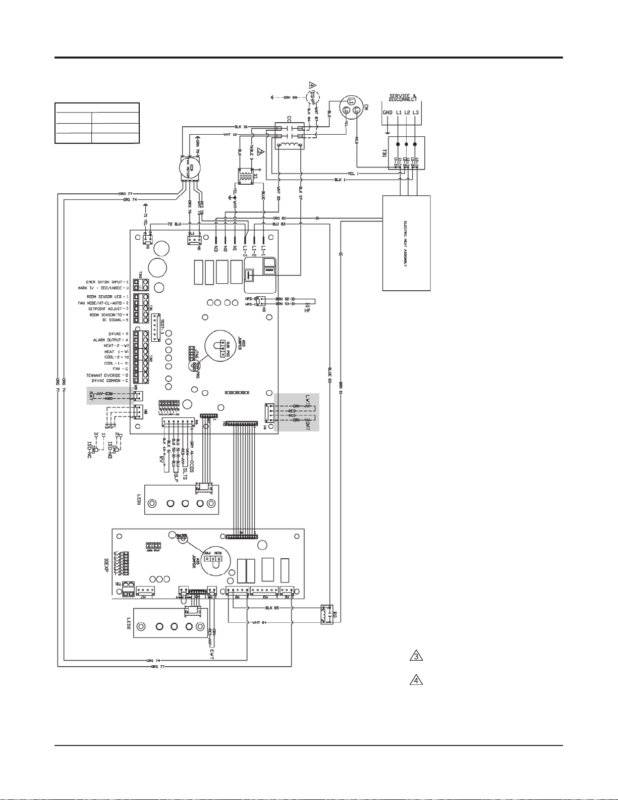
Typical Wiring Diagrams
MicroTech III Unit Controller with Optional ECM Motor, Desuperheater, Electric Heat Coil and I/O Expansion
Module – 2
Table B
208V
230V ORG
460V BLK/RED
*Drawing No. 668991301
08/230/460/60 Hz/3-Phase
RED
Legend
Item Description
C1 Capacitor-Compressor
C2 Capacitor-Fan
CC Compressor - Contactor
CM Compressor - Motor
COS Condensate Overow Sensor
DAT Discharge Air Temp Sensor
EWT Entering Water Temp Sensor
HP High Pressure Switch
HTR Electric Heater Cartridge
IOEXP I/O Expansion Board / Harness
ISO-NC Isolation Valve - Normally Closed
ISO-NO Isolation Valve - Normally Open
LED1 LED Annunciator / Harness
LED2 LED Annunciator / Harness
LP Low Pressure Switch
SLTS Suction Line Temp Sensor
LWT Leaving Water Temp Sensor
MIII MicroTech III Main Board
R1 Relay - Fan Motor
R2 Relay - Electric Heat
RAT Return Air Temp Sensor
RV Reversing Valve Solenoid
TB1 Power Terminal Block
X1 Transformer
_____
Standard Unit Wiring
_ _ _
_
Optional Wiring (by others)
Notes:
1. Main board jumpers:
No jumpers shorted. All open.
2. I/O expansion board jumpers:
Jumper JP4 shorted.
Transformer:
Unused wire to be capped.
Desuperheater only available on
1
15-208-230V applications.
Note: The gray tinted areas in the wiring diagram; Leaving Water (LWT), Discharge Air (DAT) and Return Air (RAT) Temperature
sensors are shipped or are eld installed on units congured with a communication module.
*Wiring diagrams are typical. For the latest drawing version refer to the wiring diagram located on the inside of the controls access
panel of the unit.
Catalog 1103-2 McQuay Ennity Water Source Heat Pumps 73
Page 74

Typical Wiring Diagrams
MicroTech III Unit Controller with Optional ECM Motor, Desuperheater, and I/O Expansion Module
208/230/460/60/3-Phase
Table B
RED
208V
230V ORG
460V BLK/RED
*Drawing No. 668991401
Legend
Item Description
C1 Capacitor-Compressor
C2 Capacitor-Fan
CC Compressor - Contactor
CM Compressor - Motor
COS Condensate Overow Sensor
DAT Discharge Air Temp Sensor
EWT Entering Water Temp Sensor
HP High Pressure Switch
HTR Electric Heater Cartridge
IOEXP I/O Expansion Board / Harness
ISO-NC Isolation Valve - Normally Closed
ISO-NO Isolation Valve - Normally Open
LED1 LED Annunciator / Harness
LED2 LED Annunciator / Harness
LP Low Pressure Switch
SLTS Suction Line Temp Sensor
LWT Leaving Water Temp Sensor
MIII MicroTech III Main Board
R1 Relay - Fan Motor
R2 Relay - Electric Heat
RAT Return Air Temp Sensor
RV Reversing Valve Solenoid
TB1 Power Terminal Block
X1 Transformer
_____
Standard Unit Wiring
_ _ _
_
Optional Wiring (by others)
Notes:
1. Main board jumpers:
No jumpers shorted. All open.
2. I/O expansion board jumpers:
Jumper JP4 shorted.
Transformer:
Unused wire to be capped.
Desuperheater only available on
1
15-208-230V applications.
Note: The gray tinted areas in the wiring diagram; Leaving Water (LWT), Discharge Air (DAT) and Return Air (RAT) Temperature
sensors are shipped or are eld installed on units congured with a communication module.
*Wiring diagrams are typical. For the latest drawing version refer to the wiring diagram located on the inside of the controls
access panel of the unit.
74 McQuay Ennity Water Source Heat Pumps Catalog 1103-2
Page 75

Typical Wiring Diagrams
MicroTech III Unit Controller with PSC Motor, Desuperheater and I/O Expansion Module for Hot Gas Reheat
Control (Unit Sizes 019-070) 208/230/60/1-Phase
Table B
RED
208V
230V ORG
*Drawing No. 669007101A
Legend
Item Description
C1 Capacitor-Compressor
C2 Capacitor-Fan
CC Compressor - Contactor
CM Compressor - Motor
COS Condensate Overow Sensor
DAT Discharge Air Temp Sensor
EWT Entering Water Temp Sensor
HP High Pressure Switch
HTR Electric Heater Cartridge
IOEXP I/O Expansion Board / Harness
ISO-NC Isolation Valve - Normally Closed
ISO-NO Isolation Valve - Normally Open
DSHP Desuperheater Pump
HGRH 3-Way Valve Solenoid
P1 24 VAC Supply I/O Expansion Brd.
LED1 LED Annunciator / Harness
LED2 LED Annunciator / Harness
LP Low Pressure Switch
SLTS Suction Line Temp Sensor
LWT Leaving Water Temp Sensor
MIII MicroTech III Main Board
R1 Relay - Fan Motor
R2 Relay - Electric Heat
RAT Return Air Temp Sensor
RV Reversing Valve Solenoid
TB1 Power Terminal Block
X1 Primary 24 VAC Transformer
X2 Secondary 24 VAC Transformer
_____
Standard Unit Wiring
_ _ _
_
Optional Wiring (by others)
Notes:
1. Main Board Jumpers:
JP3 Geothermal.
2. I/O Expansion Board Jumpers:
JP4 Hot Gas Reheat.
JP3 Supplemental EH.
JP4 Boilerless EH.
JP5 2-Speed Fan
Transformer:
Unused wire to be capped.
Note: The gray tinted areas in the wiring diagram; Leaving Water (LWT), Discharge Air (DAT) and Return Air (RAT) Temperature
sensors are shipped or are eld installed on units congured with a communication module.
*Wiring diagrams are typical. For the latest drawing version refer to the wiring diagram located on the inside of the controls
access panel of the unit.
Catalog 1103-2 McQuay Ennity Water Source Heat Pumps 75
Page 76

Engineering Guide Specications
General
Units shall be supplied completely factory assembled, piped, internally wired, fully charged with [R-410A, vertical unit sizes
009-070] and capable of operation with an entering water temperature range from [55°F to 110°F on models VFC] [30° to 110°F
(-6.7°C to 49°C) on models VFW]. All equipment must be rated and certied in accordance with ARI / ISO 13256-1, ETL, ETL
and have correct ARI / ISO and ETL labels mounted on side of the cabinets. Each unit shall be run tested at the factory. The
installing contractor shall be responsible for furnishing and installing McQuay Water Source Heat Pumps as indicated on the
plans and per installation instructions.
Casing and Cabinet
The cabinet shall be fabricated from heavy gauge G-60 galvanized sheet metal with interior surfaces lined with 1/2-inch thick,
1-1/2 lb. [1/2" thick coated glass ber insulation] [3/8" thick closed-cell non-brous Rubatex IAQ insulation]. The insulation
shall have a ame spread of less than 25 and a smoke developed classication of less than 50 per ASTM E-84 and UL 723. All
berglass shall be coated and have exposed edges tucked under anges to prevent the introduction of glass bers into the air
stream. All insulation must meet NFPA 90A requirements.
The cabinet shall have a pre-painted nish as an option. Color to be Antique Ivory.
Units shall be congured in one of the following airow arrangements:
■ Left Return/Top Discharge
■ Right Return/Top Discharge
Units shall have a factory-installed 1" duct ange on the discharge of the blower and must have a minimum of two access
panels, one for the compressor compartment and one for the blower compartment. Unit shall have an insulated panel separating
the blower compartment from the compressor compartment. Units are to ship with heavy metal brackets, rubber isolators,
fasteners and washers to suspend and isolate the unit from the building.
Cabinets shall have separate openings and knockouts for entrance of line voltage and low voltage control wiring. Supply and
return water connections shall be brass FPT ttings and shall be securely mounted ush to the cabinet corner post allowing for
connection to a exible hose without the use of a back-up wrench. Unit shall have a high-density polyethylene plastic “dualsloped” drain pan with a drain connection being ush mounted to the unit casing. It is the installing contractor’s responsibility
to provide sufcient clearance so that units can be easily removed for servicing.
Filter Rack and Filters
Unit shall have a 1" (25 mm thick [throwaway] construction lter and a 1" factory-installed combination lter rack/return
air duct collar. The lters shall be removable from either side of the unit.
Unit shall have a 2" (51mm) thick construction lter factory installed when the user selects an optional 2" lter rack/return
air duct collar. The 2" lter rack is design to accommodate a standard 2" pleated lter.
Refrigerant Circuit
Units shall have a sealed refrigerant circuit, which includes a non-CFC depleting R-410A refrigerant [rotary (sizes 007-015),
and scroll compressor (sizes 019 to 070)]. In addition each unit will have a thermostatic expansion valve, an aluminum n and
ried copper tube refrigerant-to-air heat exchanger, a reversing valve and a water-to-refrigerant coaxial heat exchanger. The
coaxial coils shall be made of [copper] [or optional cupronickel] and shall be deeply uted to enhance heat transfer and minimize
fouling and scaling. The coaxial coil shall have a working pressure of 400 psig on the waterside of the unit and 500 psig on the
refrigerant side for all R-410A units.
Refrigerant metering shall be regulated by a thermostatic expansion valve (TXV) only. Reversing valve shall be four-way
solenoid activated refrigerant valve, which fails in the cooling “dominant” operation. Safety controls include a high-pressure
switch, a low-pressure switch (sizes 019 to 070 only) and a low refrigerant temperature sensor. Refrigerant gauge access ttings
shall be factory installed on high and low pressure refrigerant lines to facilitate eld service. Activation of any safety switch
shall prevent the compressor from operating. Units shall be capable of being reset only by interrupting the power supply to the
unit. Unit shall not be able to be reset from the wall thermostat.
76 McQuay Ennity Water Source Heat Pumps Catalog 1103-2
Page 77

Engineering Guide Specications
Electric Heat Coils
The optional electric heat coil (5kW or 10kW) shall be factory installed inside the unit cabinet, be integral to the supply fan
housing and be used as auxiliary or emergency heat.
Desuperheater
The optional desuperheater shall be factory installed in the compressor compartment and used to add supplemental heating,
using superheated refrigerant gas through a tube-in-tube heat exchanger to the domestic hot water supply. The desuperheater
pump shall be factory installed inside the unit compressor compartment and water lines shall be fastened to the exterior panel
with ush mounted brass NPT ttings.
Hot Gas Reheat Coil Option
The optional factory-installed hot gas reheat coil shall be used as part of a dehumidication operating sequence. The hot gas
reheat coil shall be enabled when the space humidity level is above a user selectable set point. Typically, 50 to 55% RH. Hot
gas shall be diverted to the reheat coil only when the unit is in the cooling mode of operation.
Motorized Isolation Valves
The optional 2-way motorized isolation valves shall be factory installed inside the compressor compartment. The valve actuator
shall be factory wired to the Microtech III controller and be controlled when there is a call for heating or cooling.
Drain Pan
The condensate pan shall be constructed of high impact IAQ, High Density Polyethylene (HDPE) plastic to prevent corrosion
and sweating. The bottom of the drain pan shall be sloped on two planes to provide complete drainage of water from the pan.
The water source heat pump unit shall be supplied with standard solid-state electronic condensate overow protection.
Fan and Motor Assembly
Units 6 tons and smaller shall have a direct drive centrifugal fan. The fan housing shall have a removable orice ring to
facilitate fan motor and fan wheel removal. The fan housing shall protrude through the cabinet to facilitate eld supply duct
connection. The standard fan motor shall be PSC type isolated from the fan housing and shall have internal thermal overload
protection. Units above one ton shall have a terminal strip mounted on the fan motor to facilitate motor speed change. The fan
and motor assembly must be capable of overcoming the external static pressures as shown on the schedule. An ECM motor shall
be optional for unit sizes 019 thru 070. The ECM motor shall deliver precise speed and economical performance regardless of
system static pressure.
Electrical
A control box shall be located within the unit and shall contain controls for compressor, reversing valve and fan motor operation
and shall have either, a 50VA or (optional) 75VA transformer and a terminal block for low voltage eld wiring connections. Unit
shall be name-plated to accept time delay fuses or HACR circuit breaker for branch over-current protection of the power source.
Unit control system shall provide heating or cooling as required by the set points of the wall thermostat. The unit control scheme
shall provide for fan operation simultaneous with compressor operation (fan interlock) regardless of the thermostat type. The unit
shall be capable of providing an output signal to an LED on the thermostat or to a central monitoring panel to indicate a “fault”
condition from the activation of any one of the safety switches. An optional 75VA transformer may be necessary
Catalog 1103-2 McQuay Ennity Water Source Heat Pumps 77
Page 78

Engineering Guide Specications
Solid-State Control System
MicroTech III Control System - Unit shall have a microprocessor- based control system. The unit control logic shall provide
heating and cooling operation as required by the wall thermostat set point. The control system shall provide the following for
stand-alone operation:
1. The use of standard non-programmable or programmable wall thermostats.
2. Fan operation simultaneous with the compressor (fan interlock) regardless of thermostat logic.
3. Time delay compressor operation.
4. Delayed de-energizing of the reversing valve for quiet reversing valve operation.
5. Compressor short cycle protection of a minimum of three minutes before restart is possible.
6. Random unit start-up after coming off on unoccupied mode.
7. Single grounded wire connection for activation of the unoccupied or unit shutdown modes.
8. Night setback temperature setpoint input signal from the wall thermostat.
9. Override signal from wall thermostat to override unoccupied mode for 2 hours.
10. Brownout protection to suspend unit operation if the supply voltage drops below 80% of normal.
11. Condensate overow protection to suspend cooling operation in an event of a full drain pan.
12. Suspended compressor operation upon activation of the refrigerant pressure switch(es).
13. Cooling operation activated for 60 seconds upon activation of the low suction temperature sensor -
defrost cycle.
14. Method of defeating compressor, reversing valve and fan time delays for fast service diagnostics.
15. Remote reset - Provides means to remotely reset automatic lock-outs generated by high/low pressure faults and/or
low temperature faults.
16. Fault Retry clears faults the 1st two times they occur within a 24-hour period and triggers automatic lock-out on
3rd fault.
MicroTech™ III Control with LonWorks communication module – Unit shall have a microprocessor-based control
system. The unit control logic shall communicate over a LonMark communications network. The unit controller is factory
programmed [LonMark ® 3.3 certied Application Code the current standard for new applications] and tested with all the
logic required to monitor and control heating and cooling operation. The controller sets the unit mode of operation, monitors
water and air temperatures, and can communicate fault conditions via a LonMark communications network. Units with the
MicroTech III and LonWorks communication module include return air, discharge air and leaving water temperature sensors.
Space temperature sensor options include a set-point adjustment, tenant override button, and the capability of substituting the
return air sensor with a wall-mounted room sensor.
Microtech III Control w/ BACNet Communication module – Unit shall have a microprocessor-based control system.
The unit control logic shall communicate over a BACnet communications network. The BACNet communication module shall
incorporate an Atmel ARM7 Thumb series MCU and be capable of supporting a full MSTP BACNet implementation. The
microprocessor shall also support SPI compatible communications with the MCU of the Microtech III controller. The physical
interface to a BACNet BAS network shall be through an industry standard RS-485 transceiver capable of existing on an RS485 network of up to 64 nodes. The unit controller is factory programmed and tested with all the logic required to monitor and
control heating and cooling operation. The controller sets the unit mode of operation, monitors water and air temperatures, and
can communicate fault conditions via a BACNet communications network. Units outtted with Microtech III and BACNet
Communication modules include return air, discharge air and leaving water temperature sensors. Space temperature sensor
options include a set-point adjustment, tenant override button, and the capability of substituting the return air sensor with a
wall-mounted room temperature sensor.
Each communicating unit controller performs the following unit operations:
■ Enable heating and cooling to maintain space temperature set point at the room sensor
■
Enable fan and compressor operation
■ Monitor all safety controls
■ Monitor discharge and return air temperature
■ Monitor leaving water temperature
■ Relay status of all vital unit functions
■ Support optional control outputs
78 McQuay Ennity Water Source Heat Pumps Catalog 1103-2
Page 79

Engineering Guide Specications
Unit mounted LED annunciators aid in diagnosing unit operation by indicating the water source heat pump operating mode
and alarm conditions. If there are no current alarm conditions, a green LED on the annunciator board will indicate normal
unit operating mode. If an alarm condition exists, the Microtech III unit controller will send the fault condition to the LED
annunciator, which will assist in troubleshooting the unit. Heat pumps with the MicroTech III Unit Controller with a LonWorks
Communication Module is designed to be linked with a centralized Building Automation System (BAS) through a LonMark
communications network for centralized scheduling and management of multiple heat pumps.
Wall-mounted room sensors are available to control the heating and cooling operation of each MicroTech III Water Source
Heat Pump.
Available room sensors include:
■ Room Sensor with timed override button and LED;
■ Room temperature sensor with timed-override button and set point adjustment (55 to 95 deg F);
■ Room sensor with timed-override button and set point adjustment (-3 to +3 deg F);
■ Room sensor (no options, sensor only).
Warranty
An optional 4-year extended compressor warranty covers the compressor for 5 years from the date at which the unit ships
from the factory.
An optional 4-year extended refrigeration circuit warranty covers the entire refrigeration circuit and related components for
5 years.
Field Installed Accessories
Wall Thermostat Options
■ Programmable Electronic Thermostat Two-stage heat/Two-stage cool, 7-day programmable. Subbase shall have
system "Mode/Prog" and fan "Auto/On" switches. Thermostat shall have the option of an Optional Remote Sensor.
■ Non-programmable, auto or manual changeover Two-stage heat/Two-stage cool, night setback override. Subbase
shall have system "Cool/Off/Heat/Auto" and fan "Auto/On switches. Thermostat shall have the option of an Optional
Remote Sensor.
Wall Temperature Sensor Options:
■ Wall Sensor with timed-override button.
■ Wall Sensor with timed-override button and set point adjustment (55 to 95 deg F), fan mode switch (auto/on),
operational mode button (Heat/Cool/Auto) and status LED to display fault condition.
■ Wall Sensor with timed-override button and set point adjustment (-3 to +3 deg F), fan mode switch (auto/on), operational
mode button (Heat/Cool/Auto) and status LED to display fault condition.
Hose Kits:
Two re-rated exible hoses with ASTM ratings of Flame Spread 25, Fuel Contribution 25 and Smoke Density 50 for
connection to unit and eld piping. Hose shall be covered with stainless steel braiding to prevent damage.
Valve Options:
■ Combination balancing and shutoff valve with adjustable memory stop.
■ Optional 2-way, Normally Open (N.O.) or Normally Closed (N.C.) motorized valves.
Automatic Flow Hose Kit:
The automatic ow hose kit shall include an automatic ow control valve, two ball valves, two exible hoses, a high ow Ystrainer, and may include a strainer blow-down and various other accessories. The automatic ow control valve shall be factory
set to a rated ow, and shall automatically control the ow to within 10% of the rated value over a 40 to 1 differential pressure,
operating range (2 to 80 PSID). Operational temperature shall be rated from uid freezing, to 225°F. The valve body shall be
constructed from hot forged brass UNS C37700 per ASTM B-283 latest revision.
Catalog 1103-2 McQuay Ennity Water Source Heat Pumps 79
Page 80
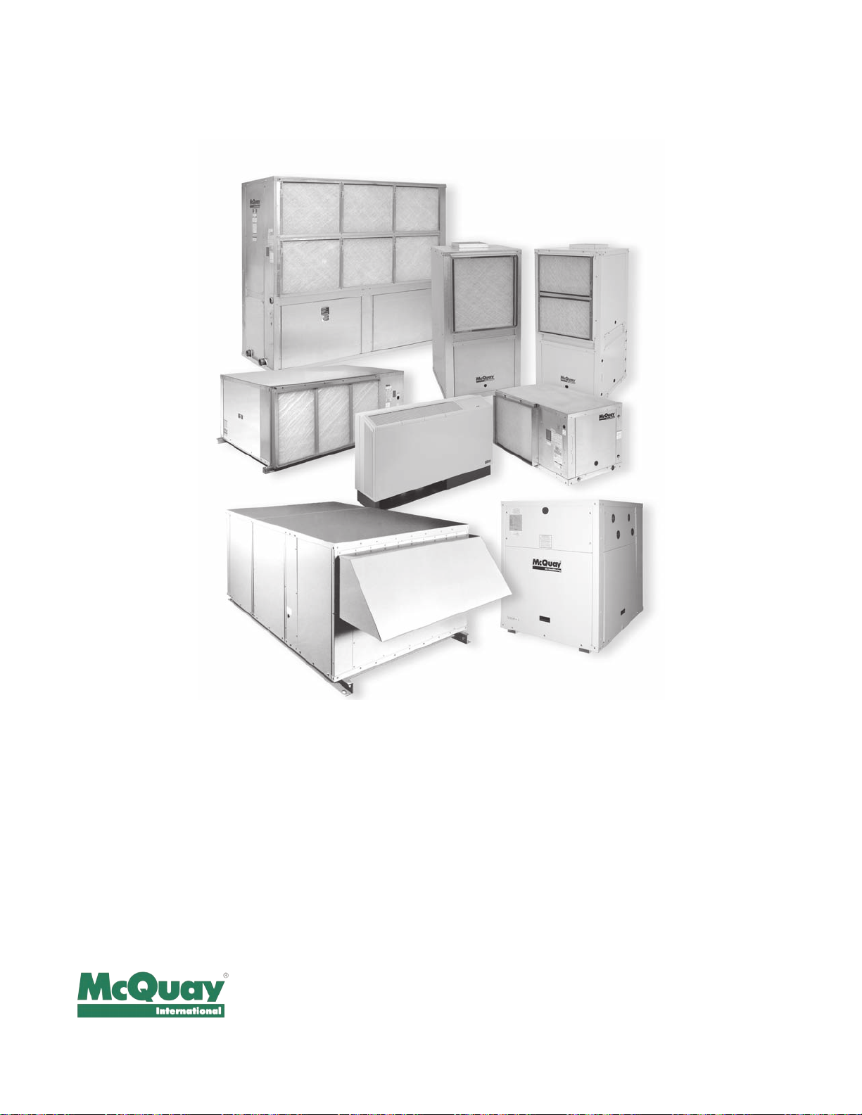
McQuay Water Source Heat Pumps
Quality Products, Flexible Congurations
Large Vertical Units
6 to 25 Ton
Large Horizontal Units
6 to 10 Ton
Ennity Vertical &
Horizontal Units
1/2 to 6 Ton
Console Units 1/2 to 1
Rooftop Units
3 to 35 Ton
1
/2 Ton
Water to Water Source
Heat Pump Units
3 to 35 Ton
Warranty
All McQuay equipment is sold pursuant to its standard terms and conditions of sale, including Limited
Product Warranty. Consult your local McQuay Representative for warranty details. Refer to Form
933-43285Y. To nd your local McQuay Representative, go to www.mcquay.com.
This document contains the most current product information as of this printing. For the most up-to-date
product information, please go to www.mcquay.com.
Products Manufactured in an ISO Certied Facility.
©2010 McQuay International (800) 432-1342 www.mcquay.com Catalog 1103-2 (4/10)
 Loading...