

Page 1
Installation Instructions 698
Solid-State Speed Controller
Steam/Hot Water Unit Heaters
Application
For remote control of air delivery, solid-state speed controllers
are available for McQuay steam/hot water unit heaters. Models
UH-18 through 108 with 115/60/1 motors (Power Code A).
A solid-state module in the controller controls motor input
voltage to maintain steady-state speed regulation at any setting
between “High” and “Low”. Controllers are packed separately
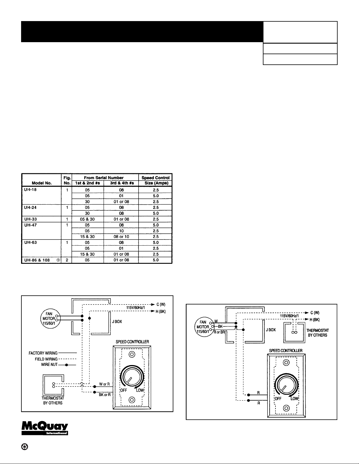
and must be connected according to wiring diagram, Figure 1
or 2.
NOTE: These controllers are not interchangeable with different
motor sizes or motor manufacturers. Before installation, check
unit heater model number, motor manufacturer and speed
controller size (listed in Amps on back of controller), to verify
compatibility. See chart below. If not matched correctly and
failure occurs, warranty will be nullified.
➀ Speed control cannot be used to turn unit on/off for 3-lead motors.
A thermostat or disconnect switch must be used.
Figure 1
Wiring Diagram
Group: Fan Coil
Date: February 2001
Installation
1. Controllers are furnished assembled and must be connected
between the fan motor and the thermostat; see Figure 1 or 2.
2. Install thermostat at desired location, (see instructions
packed with thermostat).
3. Install speed controller in a suitable location that will not
invite tampering.
Wiring Connections
1. Disconnect line voltage supply from service at the main
electrical panel. Bring power supply leads into junction box.
2. Remove speed controller cover and make wiring connections
as per the appropriate wiring diagram. CAUTION: Failure to
wire this device according to the appropriate diagram may
result in failure of the equipment or injury to the installer or user.
Operation Check
Set thermostat to lowest possible position. Turn controller to
minimum speed. Turn on power to the system. Adjust thermostat above room temperature. Motor will then start on lowest
speed. Adjust the controller to select the desired fan speed.
If motor does not start on lowest setting, the minimum control
speed may be adjusted. This can be accomplished on the 5
amp model by removing the cover plate to the controller and
turning the screw labeled MIN SPEED ADJ with a small screw
driver. Turn as indicated to increase or decrease minimum set
point. For the 2.5 amp model, the same procedure can be
followed with exception of the screw being located on the left
side of controller. If the motor still does not start, check power
supply and wiring. On new motors, bearings may be slightly
tight until motor is “broken-in”. Do not adjust speed controller
below minimum speed level until motor has experienced some
running time. Periodically repeat above procedure if lower
speeds are desired.
Figure 2
Wiring Diagram
®
4900 Technology Park Blvd., Auburn, NY 13021-9030 USA (315) 253-2771
Printed on recycled paper containing at least 10% post-consumer recycled material.
ALL WIRING MUST COMPLY WITH NATIONAL ELECTRIC CODE AND
ALL LOCAL CODES. ALL COMPONENTS MUST AGREE WITH THEIR
RESPECTIVE POWER SOURCE.
©2001 AAF-McQuay Incorporated
 Loading...