

Page 1
Installation, Operating and Maintenance Manual
IOMM TSC
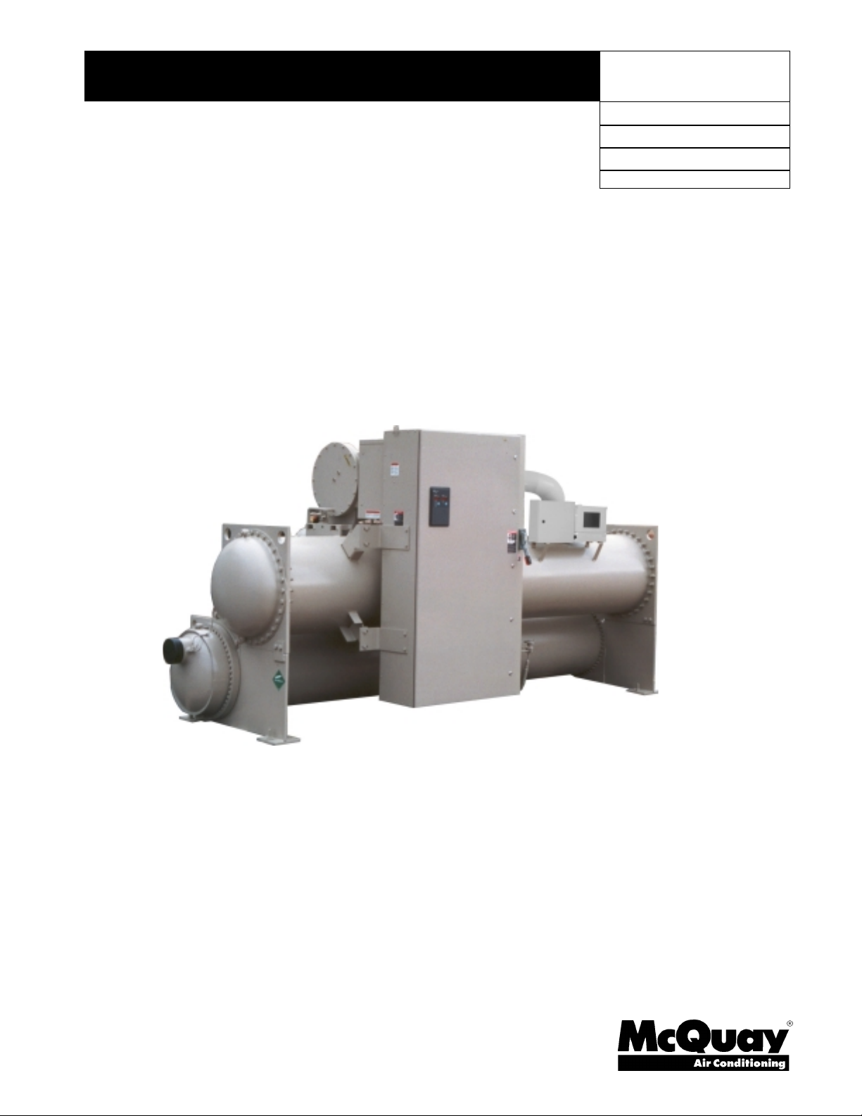
The McQuay
Templifier
Water Heater
Single Compressor Centrifugal Mod els
TSC 063, 079, 087, 100, 126
Group:
Part Number:
Effective:
Supersedes:
Chiller
January 2003
736015427
New
Page 2
Table of Contents
Introduction......................................................................................................................... 3
General Description ....................................................................................................................................3
Application.................................................................................................................................................. 3
Installation........................................................................................................................... 4
Receiving and Handling..............................................................................................................................4
Water Piping................................................................................................................................................ 6
Physical Data and Weights..........................................................................................................................7
Oil Coolers.................................................................................................................................................. 9
Relief Valves ............................................................................................................................................. 11
Electrical ................................................................................................................................................... 12
Prestart System Checklist.......................................................................................................................... 18
Operation........................................................................................................................... 19
Operator Responsibilities.......................................................................................................................... 19
Nomenclature............................................................................................................................................ 19
MicroTech II Control............................................................................................................................. 20
Capacity Control System...........................................................................................................................20
Lubrication System....................................................................................................................................23
Hot Gas Bypass.........................................................................................................................................24
Maintenance...................................................................................................................... 25
Pressure/Temperature Chart...................................................................................................................... 25
Routine Maintenance.................................................................................................................................25
Annual Shutdown...................................................................................................................................... 29
Annual Startup...........................................................................................................................................30
Repair of System....................................................................................................................................... 30
Maintenance Schedule......................................................................................................33
Service Programs.............................................................................................................. 35
Operator Schools...............................................................................................................35
McQuay" is a registered tradem ark of McQuay International
Information and illustrations cover the McQuay International products at the t i me of publication and we reserve the right to
make changes in design and construction at anytim e without notice.
2003 McQuay International
2
Centrifugal Templifier Units IOMM TSC
Page 3
Introduction
General Description
The McQuay Centrifugal Templifier Water Heaters are complete, self-contained, automatically
controlled, fluid heating units. Each unit is completely assembled and factory tested before
shipment.
Templifier units use refrigerant R-134a to reduce the size and weight of the package and operate at a
positive pressure over the entire operation range.
The controls are pre-wired, adjusted and tested. Only normal field connections such as piping,
power wiring and flow/pump/control interlocks are required, thereby simplifying installation and
increasing reliability. All necessary equipment protection and operating controls are factory
installed in the control panel.
Application
The operation and maintenance procedures presented in this manual apply to the standard TSC
family of water heaters.
All McQuay centrifugal Templifier units are factory tested prior to shipment and must be initially
started at the job site by a factory-trained McQuay service technician. Failure to follow this startup
procedure can adversely affect the equipment warranty.
One very important consideration in the operation of Templifier units is the relationship between the
source heat flowing through the evaporator and the heating load being satisfied by the unit
condenser. Figure 1 illustrates a Templifier using cooling tower water as the source of heat. The
comments following the illustration also apply for other sources of waste heat.
Figure 1, Templifier Flow Diagram
COOLING
TOWER
125°F
(52°C)
(29°C)
45°F
(7°C)
85°F
CONDENSER
EVAPORATOR
CHILLER
95°F
(35°C)
55°F
(13°C)
HEATING
LOAD
CONDENSER
EVAPORATOR
TEMPLIFIER
SUPPLE-
MENTAL
HEATER
135°F
(57°C)
90°F
(32°)
COOLING
LOAD
IOMM TSC Centrifugal Templifier units
3
Page 4

The heat being supplied to the heating load by the Templifier condenser comes from two sources:
1. The heat being absorbed in the evaporator from the waste heat stream (cooling tower water
in the diagram).
2. Compressor motor energy that goes into the refrigerant as it is compressed.
If there is insufficient source heat going to the Templifier evaporator, the unit cannot produce
sufficient heat in the condenser.
The Templifier capacity is controlled by the hot water temperature leaving the condenser, but the
temperature is reset downward as the delta-T decreases to give, in effect, a constant entering
water temperature. The leaving hot water temperature decreases with decreasing heat load.
The unit cools the source water to whatever extent is required to meet the heating load at any
given time. If there is insufficient source heat available, the Templifier unit will try to pull down
the source water temperature (perhaps to unacceptable levels) in an effort to extract the required
heat.
This will lower evaporator leaving water temperature and can cause the compressor to pump
against a higher refrigerant pressure difference than it was designed for. Centrifugal compressors
(as contrasted to reciprocating and screw compressors) are selected for a specific head (pressure
difference) for a specific job. If that head is exceeded by a relatively small amount, the
compressor can go into an undesirable stall or surge condition.
As a protection against this happening, TSC Templifier units have a special software design
(designated as "TFG") that does the following:
1. If the leaving evaporator water temperature drops below a predetermined value, the
2. If the evaporator leaving water temperature drops further, below the setpoint in #1 above, to
Insufficient source heat manifested as lower source water temperature (assuming constant flow)
can occur in closed loop systems such as cooling tower water or solar collectors, or in open loop
systems such as process waste streams or ground water.
Installation
Receiving and Handling
The unit should be inspected immediately after receipt for possible shipping damage.
All McQuay centrifugal Templifier units are shipped FOB factory and all claims for handling and
shipping damage are the responsibility of the receiver.
Insulation corners from the unit’s rigging hole locations are shipped loose and should be glued in
place after the unit is finally placed. Neoprene vibration pads are also shipped loose. Check to be
sure that these items are delivered with the unit.
controller lowers (resets) the leaving hot water setpoint. The unit is basically saying "there
is insufficient source heat and I am lowering the hot water temperature. The supplemental
heater may have to come on to make up the difference between the heating requirement and
the Templifier's limited heat output".
another lower setpoint, the controller will shut the unit off.
Leave the shipping skid (if so equipped) in place until the unit is in its final position. This will aid
in handling the equipment.
Extreme care should be used when rigging the equipment to prevent damage to the control center
or refrigerant piping. See submittal certified dimension sheets for the center of gravity of the unit.
4
Centrifugal Templifier Units IOMM TSC
Page 5
The unit can be lifted by fastening the rigging hooks to the four corners of the unit where the
rigging eyes are located (see Figure 2). Use spreader bars between the rigging lines to prevent
damage to the control center and motor terminal boxes.
Figure 2, Unit Components
Rigging
Locations
(6) Available
Evaporator
Compressor
Control Panel
Unit Control
Panel
Rigging
Locations
(6) Available
Starter, Unit
Mounting Optional
Condenser
3-Pass
Location and Mounting
Clearance
The unit must be mounted on a level concrete or steel base and have service clearance at one end
of the unit for possible removal of evaporator and/or condenser tubes. Tube clearance required is
14 feet (4.3 meters) for units with 12-foot (3.7 meters) long shells, and 11 feet (3.3 meters for units
with 9-foot (2.7 meters) long shells. Evaporator and condenser tubes are rolled into the tube sheets
to permit replacement. Service clearance on all other sides is 3 feet (1 meter), although the
National Electric Code (NEC) may require additional clearances and should be consulted.
Vibration Pads
The shipped loose neoprene vibration pads should be located under the corners of the unit (unless
the job specifications state otherwise). They are installed to be flush with the sides and outside
edge of the feet. Most TSC units have six mounting feet, although only the outer four are required.
Six pads are shipped and the installer can place pads under the middle feet, if desired.
Mounting
Make sure that the floor or structural support is adequate to support the full operating weight of the
complete unit.
It will not be necessary to bolt the unit to the mounting slab or framework; but should this be
desirable, 1 1/8" (28.5 mm) mounting holes are provided in the unit support at the four corners.
Note
: Units are shipped with refriger ant and oil valves closed to isolate these f luids for
shipment. Valves must remain closed until start-up by the McQuay technician.
IOMM TSC Centrifugal Templifier units
5
Page 6
Water Piping
Water Pumps
Note
: Avoid the use of 3600/3000 rpm (two-pole motor) pump motors. It is not
uncommon for these pumps to operate with objectionable noise and vibration.
It is also possible to build up a frequency beat due to the slight difference in the operating rpm of
the pump motor and the McQuay compressor motor. McQuay encourages the use of 1750/1460
rpm (four-pole) pump motors whenever possible.
Evaporator and Condenser Water Piping
All evaporators and condensers come standard with groove-type nozzles for Victaulic couplings
(also suitable for welding) or optional flange connections. The installing contractor must provide
matching connections of the size and type required.
CAUTION
If welding is to be performed on the mechanical or flange connections,
the solid-state temperature sensor and thermostat bulbs must be removed from the
wells to prevent damage to those components.
The unit must be properly grounded or severe damage to the
MicroTech Controller II can occur.
Water pressure gauge connection taps and gauges must be provided in the field piping at the inlet
and outlet connections of both vessels for measuring the water flow pressure drops. The pressure
drops and flow rates are specific to the unit and job and can be found in the unit submittal
documentation. Refer to the nameplate on the vessel shells for identification.
Evaporator inlet and outlet water connections have been changed over time with design changes
in the vessel. Be sure that water inlet and outlet connections match certified drawings and
factory-stenciled nozzle markings. The condenser is connected with the coolest water entering at
the bottom to maximize subcooling.
The piping must be supported to eliminate any strain on the unit. Piping should also be
adequately insulated. Normally, the condenser hot water piping is insulated and the evaporator
piping may, or may not, be insulated, depending on its operating temperature range. A cleanable
20-mesh water strainer must be installed at the inlets of both vessels. Sufficient shutoff valves
should be installed to permit draining the water from the evaporator or condenser without
draining the complete system.
Flow Switches
A flow switch must be mounted in the leaving water line of both vessels to prove adequate water
flow before the unit can start. They also serve to shut down the unit in the event that water flow
is interrupted.
A flow switch is available from McQuay under Part Number 017503300. It is a "paddle" type
switch and adaptable to any pipe size from 1 inch to 8 inches.
Consult the manufacturer's data for the minimum flow rates required to close the switch.
Installation should be as shown in Figure 3.
6
Centrifugal Templifier Units IOMM TSC
Page 7
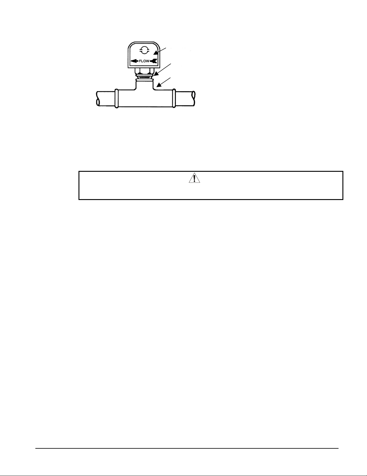
Figure 3, Flow Switch Mounti ng
Flow direction marked
on switch
I in. (25mm) NPT flow
switch connection
Tee
Electrical connections in the Unit Control Panel should be made per the field wiring diagram,
Figure 8 on page 16. The normally open contacts of the flow switch should be wired between
these two terminals. Flow switch contact quality must be suitable for 24 VAC, low current
(16ma). Flow switch wiring must be in separate conduit from any high voltage conductors (115V
and higher).
CAUTION
Freeze Notice: The evaporator and condenser are not self-draining; both must be blown
out to avoid possible tube failure if sub-freezing temperatures are possible.
The piping should also include thermometers at the inlet and outlet connections and air vents at
the high points.
The water heads can be interchanged (end for end) so that the water connections can be made at
either end of the unit. If this is done, new head gaskets must be used and the control sensors
relocated.
In cases where the water pump noise can be objectionable, vibration isolation sections are
recommended at both the inlet and outlet of the pump. In most cases, it will not be necessary to
provide vibration eliminator sections in the condenser inlet and outlet water lines.
Physical Data and Weights
Evaporator
The condenser is insulated against heat loss. Optional additional insulation may include the
evaporator and non-connection water head, suction piping, compressor inlet, motor housing, and
motor coolant suction line.
The insulation used is UL recognized (File # E55475). It is 3/4" thick ABS/PVC flexible foam
with a skin. It has a K factor of 0.28 at 75°F. The sheet insulation is fitted and cemented in place
forming a vapor barrier, then painted with a resilient epoxy finish that resists cracking.
The insulation complies to appropriate requirements or has been tested in accordance with the
following:
ASTM-C-177 ASTM-C-534 Type 2 UL 94-5V
ASTM-D-1056-91-2C1 ASTM E 84 MEA 186-86-M Vol. N
CAN/ULC S102-M88
Refrigerant-side design pressure is 200 psi (1380 kPa). Standard water-side design pressure is
150 psi (1034 kPa) with higher pressures available as an option.
IOMM TSC Centrifugal Templifier units
7
Page 8
Table 1, Evaporator Physical Data
Evaporator
Code
E1809 434 (197) 37 (138) 75 (7.0) 2734 (1239) 1
E1812 347 (158) 27 (103) 78 (7.2) 2370 (1075) 1
E2009 561 (254) 34 (164) 82 (7.6) 3026 (1371) 1
E2012 420 (190) 37 9139) 84 (7.8) 2713 (1231) 1
E2209 729 (331) 54 (206) 66 (6.1) 3285 (1488) 1
E2212 500 (227) 45 (170) 90 (8.3) 2877 (1305) 1
E2609 531 (249) 54 (295) 76 (7.1) 2730 (1238) 1
E2612 708 (321) 72 (273) 102 (9.4) 3640 (1651) 1
E3009 676 (307) 67 (252) 86 (8.0) 3582 (1625) 1
E3012 901 (409) 89 (336) 115 (10.6) 4776 (2166) 1
E3609 988 (720) 118 (445) 155 14.4) 5314 (2408) 1
E3612 1317 (597) 152 (574) 129 (11.9) 6427 (2915) 1
E4212 1757 (797) 222 (841) 148 (13.7) 8679 (3937) 1
E4812 2278 (1033) 327 (1237) 169 (15.6) 10943 (4964) 2
Notes:
1. Refrigerant charge is approximate since the actual charge will depend on other variables. Actual charge will be shown
on the unit nameplate.
2. Water capacity is based on standard tube configuration and st andard di shed heads.
3. The evaporator charge includes the maximum condenser charge available with t hat evaporator and is therefore the
maximum charge for a t otal unit with the evaporator.
Refrigerant
Charge
lb (kg)
Evaporator
Water Capacity,
gal (L)
Insulation Area
Sq Ft (m
2
)
Vessel Weight
lb (kg)
Number of
Relief
Valves
Condenser
With positive pressure systems, the pressure variance with temperature is always predictable, and
the vessel design and relief protection is based upon pure refrigerant characteristics. HFC-134a
requires ASME vessel design, inspection and testing and uses spring-loaded pressure relief
valves. When an over-pressure condition occurs, spring-loaded relief valves purge only that
amount of refrigerant required to reduce system pressure to a lower level and then close.
Refrigerant-side design pressure is 200 psi (1380 kPa). Standard water side design is 150 psi
(1034 kPa).
Pumpdown
To facilitate unit servicing, all McQuay centrifugal Templifier units are designed to permit
pumpdown and isolation of the entire refrigerant charge in the unit’s condenser.
Table 2, Condenser Physical Data
Condenser
Code
C1609 468 (213) 33 (125) 1645 (746) 2
C1612 677 (307) 33 (123) 1753 (795) 2
C1809 597 (271) 43 (162) 1887 (856) 2
C1812 845 (384) 44 (166) 2050 (930) 2
C2009 728 (330) 47 (147) 1896 (860) 2
C2012 971 (440) 62 (236) 2528 (1147) 2
C2209 822 (372) 73 (278) 2596 (1169) 2
C2212 1183 (537) 76 (290) 2838 (1287) 2
C2609 1242 (563) 83 (314) 2737 (1245) 2
C2612 1656 (751) 111 (419) 3650 (1660) 2
C3009 1611 (731) 108 (409) 3775 (2537) 2
C3012 2148 (975) 144 (545) 5033 (3383) 2
C3612 2963 (1344) 234 (884) 7095 (3219) 2
C4212 3796 (1722) 344 (1302) 9984 (4529) 2
C4812 4912 (2228) 488 (1848) 12843 (5826) 4
Notes:
1. Condenser pumpdown capacity based on 90% full at 90°F.
2. Water capacity based on standard configuration and standard heads and c an be l ess with lower tube counts.
3. See Relief Valves section on page 11 for additional information.
Pumpdown
Capacity lb (kg)
Water
Capacity gal (L)
Vessel Weight
lb (kg)
Number of
Relief Valves
8
Centrifugal Templifier Units IOMM TSC
Page 9
Compressor
Table 3, Compressor Weights
Compressor Size
Weight lb (kg)
⇒
⇒
063 079 087 100 126
3200 (1440) 3200 (1440) 3200 (1440) 6000 (2700) 6000 (2700)
Oil Coolers
McQuay centrifugal Templifier units have a factory-mounted, brazed-plate, water-cooled oil
cooler, temperature controlled water regulating valve and solenoid valve. Cooling water
connections are located near the compressor (see Figure 6) and are shown on the specific unit
certified drawings.
Field water piping to the inlet and outlet connections must be installed according to good piping
practices and should include stop valves to isolate the cooler for servicing. A 1" minimum
cleanable filter (40 mesh maximum), and drain valve or plug should also be field installed.
The water supply for the oil cooler must be clean, treated, closed-loop water such as chilled water
or from a source such as city water and must be 80°F (27°C) or less. Do not use cooling tower
water. If chilled water is used, the oil cooler must be piped across the chilled water pump to
provide sufficient pressure. The water flow through the oil cooler will be adjusted by the unit's
regulating valve so that the temperature of oil leaving the oil cooler and being supplied to the
compressor is between 95°F to 105°F (35°C to 41°C).
Table 4, Oil Cooler Data
Hot Side
POE Lube
TSC 063 - 087
Flow, gpm 9.9 11.9 2.9 2.0 1.54
Inlet Temperature, °F
Outlet Temperature, °F
Pressure Drop, psi - 32.2 2.0 0.9 0.5
TSC 100 - 126
Flow, gpm 15.8 21.9 5.11 3.5 2.7
Inlet Temperature, °F
Outlet Temperature, °F
Pressure Drop, psi - 30.6 1.7 0.8 0.5
Note:
1. Pressure drops include valve on the uni t.
118.0 80.0 65.0 55.0 45.0
100.0 87.3 94.5 98.3 101.4
120.0 80.0 65.0 55.0 45.0
100.0 87.0 95.0 99.0 102.3
Cold Side
Water
Cold Side
Water
Cold Side
Water
Cold Side
Water
When supplied with city water, the oil piping should discharge through a trap into an open drain to
prevent draining the cooler by siphoning. The city water can also be used for cooling tower
makeup by discharging it into the tower sump from a point above the highest possible water level.
OIL COOLER CONNECTION SIZE: All TSCs are 1 in. FPT.
IOMM TSC Centrifugal Templifier units
9
Page 10
Figure 4, Oil Cooler Piping Across Evaporator Water Pump
PUMP
CHILLER
R
STOP
VALVE
STRAINER
MAX. 40 MESH
TEMPLIFIER
OIL COOLER
SOLENOID
VALVE
S
DRAIN VALVE
OR PLUG
NOTE: Evaporator water may only be used if i t meets the criteria stated above.
Figure 5, Oil Cooler Piping With City Water
R
OIL COOLER
SOLENOID
S
VALVE
STOP
VALUE
Oil
Reservoir
Solenoid
Valve
Temperature
Control Valve
WATER
SUPPLY
STOP
VALVE
STRAINER
MAX. 40
MESH
DRAIN VALVE
OR PLUG
Figure 6, Oil Cooler Connections, TSC Units
COOLING TOWER
COOLING TOWER MAKEUP
DISCHARGE ABOVE
HIGHEST POSSIBLE
WATER LEVEL
OPEN
DRAIN
Compressor &
Lub Control
Inlet
Connection
Outlet
Connection
10
Centrifugal Templifier Units IOMM TSC
Page 11
Relief Valves
As a safety precaution and to meet code requirements, each Templifer unit is equipped with
pressure relief valves located on the condenser, evaporator, and oil sump vessel for the purpose of
relieving excessive refrigerant pressure (caused by equipment malfunction, fire, etc.) to the
atmosphere. Codes requires that relief valves must be vented to the outside of a building. Relief
piping connections to the relief valves must have flexible connectors.
Note
making pipe connections. W henever vent piping is installed, the lines should be run in
accordance with local code requirements. Where local codes do not apply, the latest issue
of ANSI/ASHRAE Standard 15 code recomm endations should be followed.
Condensers have two relief valves as a set with a three-way valve separating the two valves (large
condensers will have two such sets). One valve remains active at all times and the second valve
acts as a standby.
Remove plastic shipping plugs (if installed) from the inside of the valves prior to
:
Figure 7, Condenser 3-Way Valve
The vent line piping to a dual valve set is sized for one relief valve and piped to both valves. On
large capacity condenser designs, two separate sets of dual relief valves are used. The vent line
must be sized for the total of two valves but piped to all four.
Refrigerant Vent Piping
Relief valve connection sizes are 1-inch FPT and are in the quantity shown in Table 1 and Table 2.
Relief valves must be piped to the outside of the building in accordance with ANSI/ASHRAE 15.
Twin relief valves mounted on a transfer valve are used on the condenser so that one relief valve
can be shut off and removed leaving the other in operation. Only one of the two is in operation at
any time. Where four valves are shown in the table, they consist of two valves each mounted on
two transfer valves. Only two relief valves of the four are active at any time.
Vent piping is sized for only one valve of the set, since only one can be in operation at a time. In
no case would a combination of evaporator and condenser sizes require more refrigerant than the
pumpdown capacity of the condenser. Condenser pumpdown capacities are based on the current
ANSI/ASHRAE Standard 15 which recommendations of 90% full at 90°F (32°C). To convert
values to the older ARI standard, multiply pumpdown capacity by 0.888.
IOMM TSC Centrifugal Templifier units
11
Page 12

Sizing Vent Piping (ASHRAE Method)
Relief valve pipe sizing is based on the discharge capacity for the given evaporator or condenser
and the length of piping to be run. Discharge capacity for HFC-134a vessels is calculated using a
complicated equation that accounts for equivalent length of pipe, valve capacity, Moody friction
factor, pipe ID, outlet pressure and back pressure. The formula, and tables derived from it, are
contained in ASHRAE Standard 15-2001.
McQuay centrifugal Templifier units have the following relief valve settings and discharge
capacity:
TSC evaporator and condenser = 200 psi, 75.5 lb of air/min
Since the pressures and valve size are fixed for McQuay Templifier units, the above sizing equation
can be reduced to the simple table shown below. The table gives the pipe size required
When valves are piped together, the common piping must follow the rules set out in the following
paragraph.
Table 5. Relief Valve Piping Sizes
Equivalent length (ft) 3.8 21.1 113.0 313.0 1021.2 4307.6
Pipe Size inch (NPT) 1 1/4 1 1/2 2 2 1/2 3 4
Moody Factor 0.0209 0.0202 0.0190 0.0182 0.0173 0.0163
NOTE: A 1-inch pipe is too small to handle these valves. A pipe increaser must always be installed at the valve outlet.
Common Piping
According to ASHRAE Standard 15, the pipe size can not be less than the relief valve outlet size.
The discharge from more than one relief valve can be run into a common header, the area of which
can not be less than the sum of the areas of the connected pipes. For further details, refer to
ASHRAE Standard 15. The common header can be calculated by the formula:
per valve
.
.
D
Common
122
22
....
DDD
=+
05
n
The above information is a guide only. Consult local codes and/or latest version of ASHRAE
Standard 15 for sizing data.
Electrical
Wiring, fuse and wire size must be in accordance with the electrical information located in the
submittal data. Refer to electrical data supplied with the unit or McQuay Product Manual PM
Templifier.
NOTE
voltage unbalance between phases must not exceed 3%. Since a 3-1/2% voltage
unbalance will cause an approximate 25% increase in motor temperature, it is most
important that the unbalance between phases be kept at a minimum.
Power Wiring
Power wiring to compressors must be in the proper phase sequence. Motor rotation is set up for
clockwise rotation facing lead end with phase sequence of 1-2-3. Care should be taken that proper
phase sequence is carried through the starter to the compressor. With the phase sequence of 1-2-3
: The voltage to these units must be within ±10% of nameplate voltage, and the
WARNING
Qualified and licensed electricians must perform wiring. Shock hazard exists.
12
Centrifugal Templifier Units IOMM TSC
Page 13
and L1 connected to T1 and T6, L2 connected to T2 and T4, and L3 connected to T3 and T5,
rotation is proper. See diagram in terminal box cover.
The McQuay start-up technician will check proper phase sequence. Compressors are “bumped” at
initial startup and correct rotation is visually confirmed.
NOTE
: Connections to terminals must be made with copper lug s and copper wire. Care
should be taken when attaching leads to compressor ter m inals.
NOTE
: Do not make final connections to m otor terminals unt il wiring has been checked and
approved by the McQuay technician.
CAUTION
Under no circumstances should a compressor be brought up to speed unless proper
sequence and rotation have been established.
Serious compressor damage can result if it starts in the wrong direction.
It is the installing contractor's responsibility to insulate the compressor motor terminals when the
unit voltage is 600 volts or greater. This is to be done after the McQuay start-up technician has
checked for proper phase sequence and motor rotation.
Following this verification by the McQuay technician, the contractor should apply the following
furnished items.
Materials required:
1. Locktite brand safety solvent (12 oz. package available as McQuay part number
350A263H72)
2. 3M Co. Scotchfil brand electrical insulation putty (available in a 60-inch roll as McQuay
part number 350A263H81)
3. 3M Co. Scotchkote brand electrical coating (available in a 15 oz. can with brush as
McQuay Part Number 350A263H16)
4. Vinyl plastic electrical tape
The above items are also available at most electrical supply outlets.
Application procedur e:
1. Disconnect and lock out the power source to the compressor motor.
2. Using the safety solvent, clean the motor terminals, motor barrel adjacent to the terminals,
lead lugs and electrical cables within the terminal 4OX to remove all dirt, grime, moisture
and oil.
3. Wrap the terminal with Scotchfil putty, filling in all irregularities. The final result should
be smooth and cylindrical.
4. Doing one terminal at a time, brush the Scotchkote coating on the motor barrel to a
distance of up to 1/2 inch around the terminal, and on the wrapped terminal, the rubber
insulation next to the terminal and the lug and cable, for approximately 10". Wrap
additional Scotchfil putty insulation over the Scotchkote coating.
5. Tape the entire wrapped length with electrical tape to form a protective jacket.
6. Finally, brush on one more coat of Scotchkote coating to provide an extra moisture barrier.
IOMM TSC Centrifugal Templifier units
13
Page 14

Control Wiring
The 115-volt control power is supplied from a control transformer in the starter or from a separate
power source (meeting the requirements of McQuay Specification R35999901). Either source must
be properly fused with 20 amp dual element fuses, or with a circuit breaker selected for motor duty.
If the control transformer, or other power source for the control panel, is remote from the unit,
conductors must be sized for a maximum voltage drop of 3%. Required circuit ampacity is 20 amps
at 115 volts. Conductor size for long runs between the control panel and power source, based upon
National Electrical Code limitations for 3% voltage drop, can be determined from the table below.
Control Power Line Sizing
Maximum Length, ft (m) Wire Size (AWG) Maximum Length, ft (m) Wire Size (AWG)
0 (0) to 50 (15.2) 12 120 (36.6) to 200 (61.0) 6
50 (15.2) to 75 (22.9) 10 200 (61.0) to 275 (83.8) 4
75 (22.9) to 120 (36.6) 8 275 (83.8) to 350 (106.7) 3
Notes:
1. Maximum length is the distance a c onductor will traverse between the control power source and the unit control
panel.
2. Panel terminal connectors will accommodate up to number 10 AWG wire. Larger c onductors will require an
intermediate juncti on box.
The disconnect switch should be tagged to prevent current interruption. The switch is to remain
on at all times (except during servicing) in order to keep the oil and compressor casing
heaters operative and to prevent refrigerant from diluting the oil.
The unit Off/On switch, located in the Unit Control Panel, should be turned to the "Off" position
any time compressor operation is not desired.
In the event a transformer supplies control voltage, the transformer should be rated at 3 KVA, with
an inrush rating of 12 KVA minimum at 80% power factor and 95% secondary voltage. For control
wire sizing, refer to N.E.C. Articles 215 and 310. In the absence of complete information to permit
calculations, the voltage drop should be physically measured. Again, the disconnect switch should
be marked to prevent the control circuit from being de-energized except during panel servicing.
Water flow interlock terminals are provided on the control center terminal strip. See field
connection diagram in the Electrical Data Section or inside the cover of control panel door for
proper connections.
Flow Switches
The purpose of the water flow interlocks is to prevent compressor operation until such time as both
the evaporator water and condenser water pumps are running and flow is established through the
vessels. If flow or pressure differential switches are not factory-installed and wired as an option,
they must be furnished and installed by others before the unit can be started.
System Pumps
Operation of the evaporator water pump and hot water pump can be to 1) cycle the pump with the
compressor, 2) operate continuously, or 3) start automatically by a remote source. The pump starter
holding coils must be rated at 115 volts, 60 Hz with a maximum 100-volt-amperage rating. If the
voltage-amperage rating is exceeded, a control relay is required.
14
Centrifugal Templifier Units IOMM TSC
Page 15

Interlocks
All interlock contacts must be rated for no less than 10 inductive amps. The alarm circuit provided
in the control center utilizes 115-volts AC. The alarm used should not draw more than 10 voltamperes.
Control Panel Switches
Three On/Off switches are located in the upper left corner of the main Unit Control Panel, which is
adjacent to the operator interface panel, and have the following function:
UNIT shuts down the chiller through the normal shutdown cycle of unloading the
•
compressor(s) and provides a post-lube period.
COMPRESSOR (one switch for each compressor on a unit), executes an immediate shutdown
•
without the normal shutdown cycle.
CIRCUIT BREAKER disconnects optional external power to system pumps and tower fans.
•
A fourth switch located on the left outside of the Unit Control Panel and labeled EMERGENCY
STOP SWITCH stops the compressor immediately. It is wired in series with the COMPRESSOR
On/OFF switch.
Surge Capacitors
All units (except those with solid state starters or VFDs) are supplied with standard surge
capacitors to protect compressor motors from electrical damage resulting from high voltage spikes.
For unit-mounted starters, the capacitors are factory-mounted and wired in the starter enclosure.
•
For free-standing starters, the capacitors are mounted in the motor terminal box and should be
•
connected to the motor terminals with leads less than 18 inches (460 mm) long when the motor
is being wired.
IOMM TSC Centrifugal Templifier units
15
Page 16

Figure 8, Field Wiring Diagram
MICROTECH CONTROL
BOX TERMINALS
(115V) (24V)
UTB1
PE
GND
POWER
*
NOTE 7
NEUTRAL
54
85
86
70
80
55
74
86
86
79
73
78
77
76
75
(NOTE 4)
SWITCH
DELTA P
FLOW OR
EVAP.
*
MODE
SWITCH
(NOTE 4)
SWITCH
DELTA P
FLOW OR
COND.
* REMOTE
ON/OFF
(NOTE 3)
NOTE 5
*
EP2
NOTE 7
*
NOTE 5
EP1
NOTE 7
O
*
NOTE 6
NOTE 7
H
O
A
EWI-2
H
A
C
EWI-1
CP2
C
* EVAPORATOR
WATER
PUMP
STARTERS
H
O
A
C
CWI-2
COMMON
*
NOTE 2
POWER
L1 L2 L3
-LINE-
COMPRESSOR
MOTOR
STARTER
(NOTE 1)
-LOAD-
81
82(NO)
83(NC)
84
CTB2
23(5A)
24(5)
T3-S
CP1
25
1
2
3
4
6
11
12
22
EF
CF
GND
ALARM
RELAY
A
(NOTE 2)
MICROTECH
COMPRESSOR CONTROL
BOX TERMINALS
CTB1
NOTE 2
115VAC
PE
L1
L2CP2
23
24
25
1
2
3
4
11
11
12
22
NOTE 2
LESS
THAN
30V
OR
24VAC
NOTE 6
*
-COMPRESSOR TERMINALS-
-STARTER LOAD SIDE TERMINALS WYE- DELTA
T1 T2 T3
-COMPRESSOR TERMINALS-
-STARTER LOAD SIDE TERMINALS SOLID STATE
-COMPRESSOR TERMINALS-
- FOR DC VOLTAGE AND 4-20 MA
CONNECTIONS (SEE NOTE 9)
- FOR DETAILS OF CONTROL
REFER TO COMPRESSOR CONTROL
SCHEMATIC: 330342201
- UNIT CONTROL SCHEMATIC 330342101
- LEGEND: 330343001
T4 T5 T6
T4 T5 T6T1 T2 T3
T1 T2 T3
T4 T3 T5T1 T6 T2
CP1
NOTE 7
H
O
A
CWI-1
* CONDENSER
WATER
PUMP
STARTERS
C
16
Centrifugal Templifier Units IOMM TSC
Page 17

Electrical Diagram Notes
1. Compressor motor starters may be factory-mounted and wired or mounted and wired in the
field. All line side power conductors must be copper.
2. A customer-furnished 24-volt alarm relay coil can be connected between terminals 81 and
82 of the control panel for normally-open contacts and terminals 81 and 83 for normallyclosed contacts. Maximum rating of the alarm relay coil is 25-VA.
3. Remote On/Off enabling control can be accomplished by installing a set of dry contacts
between terminals 70 and 54.
4. Evaporator and condenser paddle-type flow switches or pressure differential switches are
required and must be wired as shown. Field-supplied pressure differential switches must be
installed across the vessel and not the pump.
5. Optional customer-supplied 115VAC, 25-VA maximum coil rated source water pump relay
(CHWR 1 and 2) can be wired as shown. This option will cycle the source water pump in
response to load.
6. The condenser water pump(s) can be cycled with the unit if desired. A customer supplied
115-VAC 25-VA maximum coil rated condenser water pump relay (CWR 1 and 2) can be
wired as shown.
7. Auxiliary 24-VAC rated contacts in both the evaporator water and condenser water pump
starters may be wired as shown to provide additional flow protection.
8. DC wiring must be run separately from 115VAC wiring.
9. All wiring to be NEC Class 1.
IOMM TSC Centrifugal Templifier units
17
Page 18

Prestart System Checklist
Yes No N/A
Evaporator Water
Piping complete................................................................................................................. !!!
Water system filled, vented................................................................................................ !!!
Pumps installed, (rotation checked), strainers cleaned...................................................... !!!
Controls (3-way bypass valves, etc.) operable................................................................... !!!
Water system operated and the flow balanced to meet unit design requirements .............. !!!
Condenser Water
Pumps installed, (rotation checked), strainers cleaned ..................................................... !!!
Controls operable ............................................................................................................. !!!
Water system operated and the flow balanced to meet unit requirements ......................... !!!
Electrical
115-volt service completed (if not factory-installed), but not connected to control panel !!!
Power leads connected to starter; load leads run to compressor ready for
connection when start-up technician is on hand for start-up........................................... !!!
(Do not connect starter or compressor terminals)
All interlock wiring complete between control panel and complies with specifications ... !!!
Starter complies with specifications ................................................................................. !!!
Wiring complies with National Electrical Code and local codes ...................................... !!!
(CWR) condenser pump starting relay installed and wired (if used) ................................ !!!
Miscellaneous
Oil cooler water piping complete...................................................................................... !!!
Relief valve piping complete ............................................................................................ !!!
Thermometer wells, thermometers, gauges, control wells, controls, etc., installed .......... !!!
Minimum system load of 80% of machine capacity available for testing
and adjusting controls........................................................................................................ !!!
Note
: This checklist must be completed and sent to the local McQuay service location two
weeks prior to start-up.
18
Centrifugal Templifier Units IOMM TSC
Page 19

Operation
Operator Responsibilities
It is important that the operator become familiar with the equipment and the system before
attempting to operate the Templifier Water Heater.
During the initial startup of the Templifier unit, the McQuay technician will be available to answer
any questions and instruct in the proper operating procedures.
It is recommended that the operator maintain an operating log for each individual unit. In addition, a
separate maintenance log should be kept of the periodic maintenance and servicing activities.
This McQuay centrifugal Templifier unit represents a substantial investment and deserves the
attention and care normally given to keep this equipment in good working order. If the operator
encounters abnormal or unusual operating conditions, it is recommended that a McQuay service
technician be consulted.
McQuay International conducts training for centrifugal operators at its factory Training Center in
Staunton, Virginia, several times a year. These sessions are structured to provide basic classroom
instruction and include hands-on operating and troubleshooting exercises. For further information,
contact your McQuay representative.
Nomenclature
Each unit is assigned a serial number and style number that are used to describe the unit features and
to identify each individual unit. These numbers are stamped on each unit nameplate located on the
right side of the Unit Control Panel. All inquiries pertaining to operating and servicing of this unit
should include this number.
Each vessel, and the compressor, also has a nameplate to provide certain necessary information to
the installer and the operator.
Compressors are designated as model CE. For example, a model CE 063 compressor is used on a
model TSC 063 unit. The compressor nameplate identifies the compressor model, style and serial
number and includes the electrical characteristics of the compressor motor.
The condenser and evaporator vessels have nameplates stamped with the maximum working pressure
of the vessel, the National Board Number, and the vessel style number. Note that the vessel relief
valve maximum settings coincides with the maximum refrigerant side vessel working pressure.
IOMM TSC Centrifugal Templifier units
19
Page 20

MicroTech II
Figure 9, MicroTech II Control Panel
Building Automation System (BAS) interface (if applicable) utilizing the MicroTech II controller’s
Protocol Selectability feature will be set-up by the McQuay startup service technician.
Control
TSC Templifier units are equipped with the McQuay
MicroTech II control system consisting of:
Operator touchscreen interface panel (shown at
•
the left). It consists of a 10-inch Super VGA
color screen and a floppy drive.
Unit Control Panel containing the MicroTech II
•
unit controller and miscellaneous switches and
field connection terminals.
Compressor Control Panel containing the
•
MicroTech II compressor controller and lube
system control components.
NOTE: Detailed information on the operation of the
MicroTech II control is contained in the OM
CentrifMicro II operating manual.
Capacity Control System
The opening or closing of the compressor inlet vanes controls the quantity of refrigerant that enters
the impeller, thereby controlling the compressor capacity. The vane movement is actuated by a
piston that moves in response to oil pressure controlled from the SA or SB solenoid valves which, in
turn, respond to a load/unload signal from the MicroTech II controller.
Vane Operation
The hydraulic system for the inlet guide vane, capacity control operation consists of a 4-way
normally open solenoid valve located on the compressor, close to the suction connection. Oil under
pressure from the oil filter is directed by the 4-way valve to either or both sides of the piston,
depending on whether the control signal is to load, unload, or hold.
To open the vanes (loading the compressor), solenoid SA is de-energized and solenoid SB is
energized, allowing oil flow from port SA to one side of the piston, then drain through port SB.
To close the vanes (unloading the compressor), valve SB is de-energized and valve SA is energized,
moving the piston and vanes toward the unload position.
When both solenoid valves SA and SB are de-energized, full and equal oil pressure is directed to
both sides of the piston through ports SA and SB and the vanes are held in a stop position. Refer to
Figure 12 and Figure 13 for solenoid action. Note that both solenoids cannot be
simultaneously.
Metering Needle Valves
The speed at which the capacity control vanes are opened or closed can be adjusted to suit system
operating requirements. Adjustable needle valves in the oil drain lines are used to control the rate of
bleed-off and consequently the vane speed. These needle valves are part of the 4-way solenoid valve
assembly located on the compressor inlet assembly.
energized
20
See Vane Speed Adjustment
Centrifugal Templifier Units IOMM TSC
Figure 10
, on page 21.
Page 21

The valves are normally factory set so the vanes will move at the speeds shown in Table 6. The
)
speed should be slow enough to prevent over-controlling and hunting.
Vane Speed Adjustment
Figure 10, Needle Valve Location
The left adjusting screw is the SB needle valve
for adjusting the vane OPENING speed for
loading the compressor. Turn this screw
clockwise to decrease the vane opening speed
and counterclockwise to increase the opening
speed.
The right adjusting screw is the SA needle
valve for adjusting the CLOSING speed to
unload the compressor. The same adjustment
method applies; clockwise to decrease closing,
counterclockwise to increase vane closing.
These adjustments are sensitive. Turn the
adjusting screws a few degrees at a time.
The vane speed is factory set and varies by
compressor size:
The start-up technician may readjust the vane
speed at initial start-up to meet job conditions.
Open (Load)
Table 6, Vane Speed, Factory Setting
Compressor Model Opening Time Closing Time
CE063 - CE100 3 - 5 min. 1 - 2 min
CE126 5 - 8 min. 1 - 2 min.
Close (Unload
Figure 11, Oil Sump and Compressor Controller Panel
Relief Valve
Oil Sump
Solenoid
Valve
Temperature
Control Valve
: 4-way solenoid valve and vane close switches are located on the compressor
NOTE
suction inlet. The mechanical high-pressure cutout is located in the discharge line.
Back Seat Port
Oil Pump
Contactor
Oil Pump
Capacitor
Compressor
MicroTech II
controller
Cooling
Water Inlet
Cooling
Water Outlet
IOMM TSC Centrifugal Templifier units
21
Page 22

Figure 12, Vane Control Solenoid Operation
Piston Drain
SB
SA
LEGEND
Section “SB”
De-energized
HOLDING
Compressor
Unloader
Cylinder
Floating Piston Linked to Inlet Vanes
Opens Vanes
Closes Vanes
Four-Way Solenoid
Valve Located on
Compressor or
in Lube Box
Adjustable Needle Valves
Integral With Four-Way
Solenoid Valve
#3 Outlet
#1 Inlet
Figure 13, Vane Control Solenoid Operation, Continued
LEGEND
OPENING
Oil Under Pressure
To Oil
Pump Sump
Section “SA”
De-energized
From Oil
Pump Discharge
Oil Under Pressure
Oil Sump Pressure
CLOSING
Drain From Piston
Drain From Piston
#3 Outlet
SB
SA
#1 Intlet
#3 Outlet
SB
SA
#1 Intlet
To Oil
Pump Sump
Section “SB”
Energized
Section “SA”
De-energized
From Oil
Pump Discharge
Piston Drain
To Oil
Pump Sump
Section “SB”
De-energized
Section “SA”
Energized
From Oil
Pump Discharge
22
Centrifugal Templifier units IOMM TSC
Page 23

Lubrication System
The lubrication system provides lubrication and heat removal for compressor bearings and
internal parts. In addition, the system provides lubricant under pressure to hydraulically
operate the unloading piston for positioning the inlet guide vanes for capacity control.
Only the recommended lubricant, as shown in Table 7, can be used for proper operation of
the hydraulic system and bearing lubrication system. Each unit is factory charged with the
correct amount of the recommended lubricant. Under normal operation, no additional
lubricant is needed. Lubricant should be visible in the oil sump sight glass at all times.
The compressors have an lubricant pump located in the lubricant reservoir. The reservoir
includes the pump and motor, heater and lubricant/refrigerant vapor separator system.
lubricant is pumped from the lubricant sump, through the external water-cooled lubricant
cooler and then to the lubricant filter located inside the compressor housing.
The lubricant cooler maintains the proper oil temperature under normal operating
conditions. The coolant flow control valve should maintain 95°F to 105°F (35°C to 41°C)
lubricant temperature entering the compressor. A spring-loaded piston in the compressor
accomplishes lubrication protection for coast down in the event of a power failure. When
the lubricant pump is started, the piston is forced back by the lubricant pressure,
compressing the spring and filling the piston cavity with lubricant. When the pump stops,
the spring pressure on the piston forces the lubricant out to the bearings.
In models CE100 and CE126, the compressor coast down lubrication is supplied from
gravity-feed oil reservoir.
A typical flow diagram is shown in Figure 14.
Table 7, Approved Polyolester Lubricants For R-134a Units
Compressor Models CE063 - 126
Lubricant Designation
McQuay Part Number
55 Gal. Drum
5 Gal. Drum
1 Gal. Can
Compressor Oil Label 070200106
NOTE: Approved lubricant from two suppliers can be mixed.
Mobil Artic EAL 46;
ICI Emkarate RL32H
735030432
735030433
735030435
IOMM TSC Centrifugal Templifier units
23
Page 24

Figure 14, Typical Lubricant Flow Diagram
PISTON
DRAIN
HEATER
T
DRAIN
VENT
COMPRESSOR
UNLOADER
PISTON
4 WAY
SOLENOID
P
BYPASS
RELIEF
VALVE
R
TO
BEARINGS
THRUST
PUMP
FILTER
P
T
OIL
COOLER
OUT
COOLING WATER
IN
S
OIL PUMP
NOTES:
1.
Connections are not necess ari l y in the correct relative location.
2.
P = pressure sensor, T = temperature sensor, S = solenoid valve, R = reli ef valve
OIL SUMP
Hot Gas Bypass
Templifier units are usually equipped with a hot gas bypass system to feed discharge gas
directly into the evaporator at low system loads.
Light load conditions are signaled by measurement of a set percentage of RLA amps by the
MicroTech II controller. When the RLA drops to the setpoint, the hot gas bypass solenoid
is energized making hot gas bypass available for use. This introduction of hot gas provides
a stable refrigerant flow and keeps the unit from short cycling under light load conditions.
The factory setpoint for bringing on hot gas bypass is 40% of RLA.
24
Centrifugal Templifier units IOMM TSC
Page 25
Maintenance
Pressure/Temperature Chart
HFC-134a Temperature Pressure Chart
°F PSIG °F PSIG °F PSIG °F PSIG
6 9.7 46 41.1 86 97.0 126 187.3
8 10.8 48 43.2 88 100.6 128 192.9
10 12.0 50 45.4 90 104.3 130 198.7
12 13.2 52 47.7 92 108.1 132 204.5
14 14.4 54 50.0 94 112.0 134 210.5
16 15.7 56 52.4 96 115.9 136 216.6
18 17.1 58 54.9 98 120.0 138 222.8
20 18.4 60 57.4 100 124.1 140 229.2
22 19.9 62 60.0 102 128.4 142 235.6
24 21.3 64 62.7 104 132.7 144 242.2
26 22.9 66 65.4 106 137.2 146 249.0
28 24.5 68 68.2 108 141.7 148 255.8
30 26.1 70 71.1 110 146.3 150 262.8
32 27.8 72 74.0 112 151.1 152 270.0
34 29.5 74 77.1 114 155.9 154 277.3
36 31.3 76 80.2 116 160.9 156 284.7
38 33.1 78 83.4 118 166.0 158 292.2
40 35.0 80 86.7 120 171.1 160 299.9
42 37.0 82 90.0 122 176.4 162 307.8
44 39.0 84 93.5 124 181.8 164 315.8
Routine Maintenance
Lubrication (See Caution)
After the system is once placed into operation, no other additional oil is required, except in the
event that repair work becomes necessary to the oil pump, or unless a large amount of oil is lost
from the system due to a leak.
If oil must be added with the system under pressure, use a hand pump with its discharge line
connected to the back seat port of the valve in the lub drain from the compressor to the sump See
Figure 11 on page 21. The POE oils used with R-134a are hygoscopic and care must be exercised
to avoid exposure to moisture (air).
The condition of compressor oil can be an indication of the general condition of the refrigerant
circuit and compressor wear. An annual oil check by a qualified laboratory is essential for
maintaining a high level of maintenance. It is useful to have an oil analysis at initial start-up to
provide a benchmark from which to compare future tests. The local McQuay service office can
recommend suitable facilities for performing these tests.
The following table gives the upper limits for metals and moisture in the polyolester lubricants
required by McQuay chillers.
IOMM TSC Centrifugal Templifier units
25
Page 26

Table 8, Metal and Moisture Limits
Element Upper Limit (PPM) Action
Aluminum 50 1
Copper 100 1
Iron 100 1
Moisture 400 2
Silica 50 1
Total Acid Number (TAN) 0.19 3
Key to Action
1) Re-sample after 500 hours of unit operation.
a) If content increases less than 10%, change oil and oil filter and re-sample at normal
interval (usually one year).
b) If content increases between 11% and 24%, change oil and oil filter and re-sample
after an additional 500 hours of operation.
c) If content increases more than 25%, inspect compressor for cause.
2) Re-sample after 500 hours of unit operation.
a) If content increases less than 10%, change filter-drier and re-sample at normal
interval (usually one year).
b) If content increases between 11% and 24%, change filter-drier and re-sample after
an additional 500 hours of operation.
c) If content increases more than 25%, monitor for a water leak.
3) If TAN is less than 0.10, system is safe as far as acid is concerned.
a) For TAN between 0.10 and 0.19, re-sample after 1000 hours of operation.
b) For TAN above 0.19, change oil, oil filter, and filter-drier and resample at normal
interval
Changing Oil Filters
McQuay Templifier units are at positive pressure under normal standby and operating conditions
and do not leak contaminated moist air into the refrigerant circuit. This eliminates the need for
annual oil changes. An annual laboratory oil check is recommended to check overall compressor
and system condition.
The oil filter in each of these compressors can be changed by simply isolating the filter cavity.
Close the oil discharge line service valve at the oil pump (at the filter on CE100 and CE126).
Remove the filter cover. Some foaming can occur, but the internal check valve should limit
leakage from the compressor interior. Remove the filter, replace with a new element and replace
the filter cover using a new gasket. Reopen the valve in the pump discharge line and purge air
from the oil filter cavity.
When the compressor is operated again, the oil level should be checked to determine if oil needs to
be added to maintain the proper operating level.
CAUTION
Improper servicing of the lubrication system,
including the addition of excessive or incorrect oil, substitute quality oil filter,
or mishandling of the equipment under pressure can damage the compressor.
Only authorized and trained service personnel should attempt this service.
For qualified assistance, contact your local McQuay service location.
26
Centrifugal Templifier units IOMM TSC
Page 27

Filter-driers
The filter-drier is located in the motor cooling refrigerant feed line. New filter-driers have been
developed for use in compressors utilizing POE lubricants. These filter-driers are balanced to
remove moisture and acids to help system reliability.
Use ALCO “UK” series or Sporlan “CW/RCW” series driers. ALCO “W48” series or Sporlan
“HH” series can be used once or twice for system cleanup, followed by installation of “UK” or
“CW/RCW” filter-driers.
Do not leave the “HH” or “W48” cleanup driers permanently installed in the system. Prolonged
use could strip important additives out of the oil and/or they can break down.
Refrigerant Cycle
Maintenance of the refrigerant cycle should include maintaining a log of the operating conditions
and checking that the unit has the proper oil and refrigerant charge. (See the maintenance schedule
and the appropriate operating log at the end of this manual).
At every inspection, the oil, suction and discharge pressures should be noted and recorded, as well
as condenser and evaporator water temperatures. These values can be read from the operator
interface panel or downloaded from the MicroTech II History Log via a floppy drive located in the
panel (see OM CentrifMicro II).
Subcooling/Superheat
The suction line temperature at the compressor should be taken at least once a month. Subtracting
the saturated temperature equivalent of the suction pressure will give the superheat. Although the
interface screen gives this information, it is worthwhile double-checking it periodically. Extreme
changes in subcooling and/or superheat over a period of time will indicate losses of refrigerant or
possible deterioration of the expansion valves. Proper superheat setting is 0 to 1 degree F (0.5
degree C) at full load. Such a small temperature difference can be hard to measure accurately.
Another method is to measure the compressor discharge superheat, the difference between the
actual discharge temperature and the saturated discharge temperature. The discharge superheat
should be between 14 and 16 degrees F (8 to 9 degrees C) at full load with R-134a refrigerant.
The liquid injection should be deactivated (by closing the liquid injection line ball valve or
removing the leads to the injection line solenoid valve) when taking the discharge temperature.
The superheat will increase linearly to 55 degrees F (30 degrees C) at 10% load. The MicroTech
II control can display all superheat and subcooling temperatures.
Subcooling is the difference between the condenser saturated temperature and the refrigerant
liquid temperature, both measured at the condenser outlet. For a 10-degree F design condenser
water range, the subcooling should be 10-degrees F at full load, decreasing proportionally with
load to zero degrees. Another simple measurement is the entering condenser water temperature
and the leaving refrigerant liquid temperature. This difference should be about two degrees F at
full load, decreasing to one degree F at 50 % load and less.
Approach Temperature
Approach temperature is the difference between the temperature of the fluid leaving a heat
exchanger and the saturated temperature of the refrigerant in the vessel. It is a good indication of
the performance of an evaporator or condenser. McQuay’s high efficiency heat exchangers have
approach temperatures as low as 0.5 degrees F, ranging up to 2 or 3 degrees F. These small
temperature differences are hard to measure accurately, but as a rule-of-thumb, approach
temperatures in excess of 4 to 5 degrees F could indicate a problem such as plugged tubes or
excessive tube fouling. If this condition occurs, it would be prudent to remove a water head and
examine the condition of the vessel. This is especially true if an increase in pressure drop is also
observed.
IOMM TSC Centrifugal Templifier units
27
Page 28
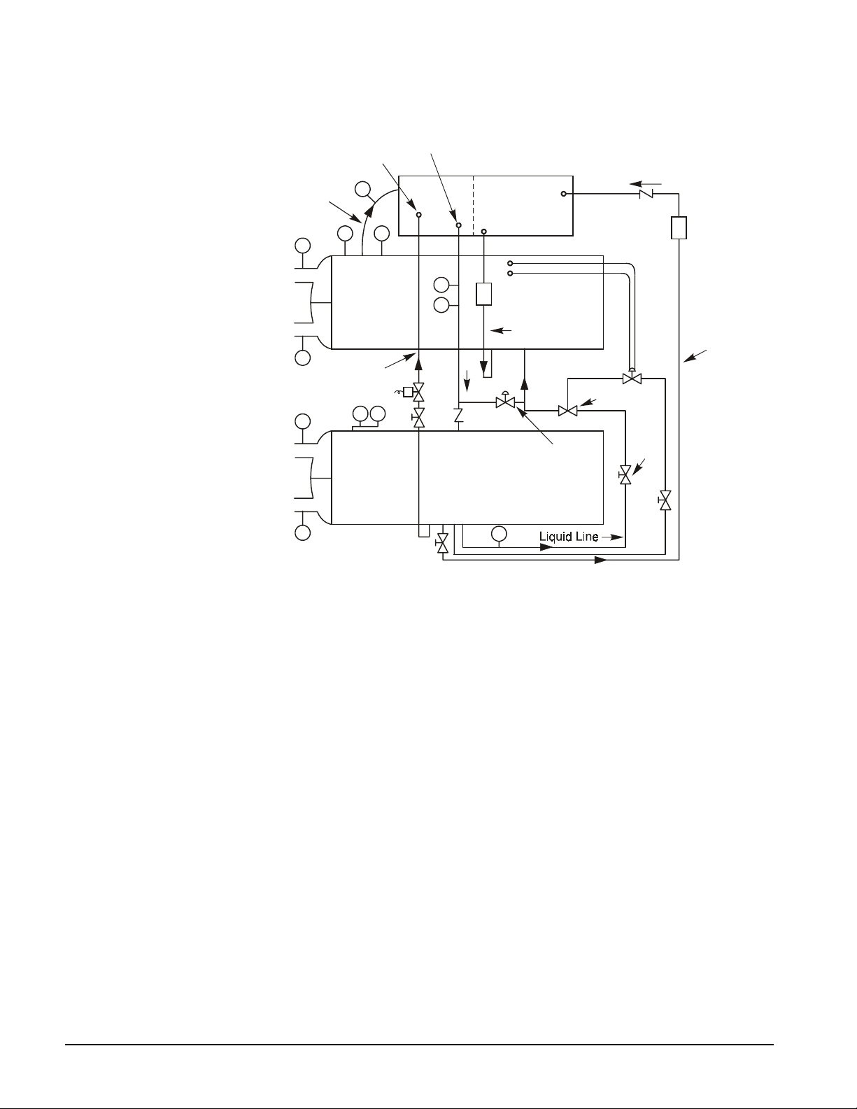
Figure 8. Typical Refrigerant Flow Diagram
Discharge
Liquid
Injection
Line
Suction
Line
T
Out
Chiller Water
In
T
Out
Condensed Water
In
T
NOTES:
1. Connections not necess ari l y i n correct relative location.
2. Secondary filter-drier used to choke off refrigerant flow in the event of a motor burnout.
3. HGBP, hot gas bypass valve is standard on Templifier units.
4. T = temperature sensor, P = pressure sensor, R = relief valve
T
R P
Evaporator
Liquid
Injection
RTR
Condenser
Motor
Cooling
Out
T
P
S
Note 2
T
Motor
Cooling
Drain
In
Hot
Gas
Bypass
Pilot
Expansion
Valve
King
Valve
Filter
Drier
Motor
Cooling
N
Electrical System
Maintenance of the electrical system involves the general requirement of keeping contacts clean
and connections tight and checking on specific items as follows:
28
1. The compressor current draw should be checked and compared to nameplate RLA value.
Normally the actual current will be lower since the nameplate rating represents full load
operation. Also check all pump and fan motor amperages and compare with nameplate
ratings.
2. Inspection should verify that the oil heaters are operative. The heaters are insert cartridge
type and can be checked by ammeter reading. They should be energized whenever power is
available to the control circuit, when the oil temperature sensor calls for heat, and when the
compressor is inoperative. When the compressor runs, the heaters are de-energized. The
Digital Output screen and second View screen on the interface panel both indicate when the
heaters are energized.
3. At least once a quarter, all equipment protection controls except compressor overloads should
be made to operate and their operating points checked. A control can shift its operating point
as it ages and this must be detected so the controls can be adjusted or replaced. Pump
interlocks and flow switches should be checked to be sure they interrupt the control circuit
when tripped.
Centrifugal Templifier units IOMM TSC
Page 29
4. The contactors in the motor starter should be inspected and cleaned quarterly. Tighten all
terminal connections.
5. The compressor motor resistance to ground should be checked and logged semi-annually.
This log will track insulation deterioration. A reading of 50 megohms or less indicates a
possible insulation defect or moisture and should be further checked.
CAUTION
Never megger a motor while in a vacuum. Severe motor damage can result.
6. The centrifugal compressor must rotate in the direction indicated by the arrow near the
rotation sight glass on the rear motor cover plate. If the operator has any reason to suspect
that the power system connections may have been altered (phases reversed), the compressor
should be jogged to check rotation. For assistance, call the McQuay service location.
Cleaning and Preserving
A common cause of service calls and equipment malfunction is dirt. This can be prevented with
normal maintenance. Remove and clean strainers in the source water system, oil cooler line and
condenser water system at every inspection.
Seasonal Servicing
Prior to shutdown periods and before starting up again, the following service procedures should be
completed.
Annual Shutdown
Where the Templifier Water heater may be subject to freezing temperatures when not operating, the
evaporator, condenser and Templifier water piping should be drained of all water. Dry air blown
through the vessels will aid in forcing all water out. Removal of condenser heads is also
recommended. The condenser and evaporator are not self-draining. Water permitted to remain in
the piping and vessels can rupture these parts if subjected to freezing temperature.
Forced circulation of antifreeze through the water circuits is one way of avoiding freeze up.
1. Take measures to prevent the shutoff valve in the water supply line from being accidentally
turned on.
2. If a cooling tower is used as a heat source, and if the water pump will be exposed to freezing
temperatures, be sure to remove the pump drain plug and leave it out so any water that
accumulates will drain away.
3. Open the compressor disconnect switch and remove the Fusetrons. If the transformer is used for
control voltage, the disconnect must remain on to provide power to the oil and casing heaters.
Set the UNIT On/Off switch to the Off position.
4. Check for corrosion and clean and paint rusted surfaces.
5. Clean and flush the water tower for all units using a water tower. Make sure tower “blowdown”
or bleed-off is operating. Set up and use a good maintenance program to prevent “liming up” of
both tower and evaporator. It should be recognized that atmospheric air contains many
contaminants that increase the need for proper water treatment. The use of untreated water can
result in corrosion, erosion, sliming, scaling or algae formation. It is recommended that the
service of a reliable water treatment company be used. McQuay International assumes no
responsibility for the results of untreated or improperly treated water.
6. If open circuit water is used in either vessel, remove the heads at least once a year to inspect the
tubes, and clean if required.
NOTE: It is of utmost importance that all local, national, and international regulations
concerning the handling and emission of refrigerants are observed.
IOMM TSC Centrifugal Templifier units
29
Page 30

Annual Startup
A dangerous condition can exist if power is applied to a faulty compressor motor starter that has
been burned out. This condition can exist without the knowledge of the person starting the
equipment.
This is a good time to check all the motor winding resistance to ground. Semi-annual checking
and recording of this resistance will provide a record of any deterioration of the winding
insulation. All new units have well over 100 megohms resistance between any motor terminal and
ground.
Whenever great discrepancies in readings occur or uniform readings of less than 50 megohms are
obtained, the motor cover should be removed for inspection of the winding prior to starting the
unit. Uniform readings of less than 5 megohms indicate motor failure is imminent and the motor
should be replaced or repaired. Repairing the motor before a failure occurs can save a great deal
of time and labor expended in the cleanup of a system after motor burnout.
1. The control circuit should be energized at all times
circuit has been off and oil is cool, energize the oil heaters and allow 24 hours for them to
heat the oil and separate refrigerant from the oil before starting.
2. Check and tighten all electrical connections.
3. Replace the drain plug in the cooling tower pump if it was removed at shutdown the previous
season.
4. Install Fusetrons in main disconnect switch (if removed).
5. Reconnect water lines and turn on supply water. Flush out vessels and check for leaks.
except
during service work. If the control
Repair of System
Pressure Relief Valve Replacement
Current condenser designs use two relief valves (1 set), separated by a three-way shutoff valve.
Very large condensers can have two sets. The 3-way valve allows either relief valve to be shut off,
but at no time can both together be shut off. In the event one of the relief valves in the two-valve
set is leaking, these procedures should be followed:
1. If the valve closest to the valve stem is leaking, back seat the three-way valve all the way,
closing the port to the leaking pressure relief valve.
2. Remove and replace the faulty relief valve. The three-way shutoff valve should remain
either fully back seated or fully forward for normal operation.
3. If the relief valve farthest from the valve stem is leaking, front seat the three-way valve and
replace the relief valve as stated above.
Evaporators have a single relief valve (some large vessels may have two singles). Three-way
valves are not used since the evaporator can be pumped down into the condenser vessel before the
evaporator relief valve is removed.
Pumping Down
If it becomes necessary to pump the system down, extreme care should be used to avoid freezing
the evaporator. Make sure that full water flow is maintained through the evaporator and condenser
while pumping down. To pump the system down, close all liquid line valves, and with water
flowing, start the compressor. Set the MicroTech II panel to the manual load. The vanes must be
open while pumping down to avoid a surge or other damaging condition.
Pump the unit down until the MicroTech II control cuts out at approximately 20 psig. It is possible
that the unit might experience a mild surge condition prior to cutout. If this should occur,
immediately shut off the compressor. Use a portable condensing unit to complete the pump down,
condense the refrigerant, and pump it into the condenser or pumpout vessel using approved
procedures.
30
Centrifugal Templifier units IOMM TSC
Page 31
Pressure Testing
No pressure testing is necessary unless some damage was incurred during shipment. Damage can be
determined by visual inspection of the exterior piping, checking that no breakage occurred or fittings
loosened. Service gauges should show a positive pressure. If no pressure is evident on the gauges, a
leak may have occurred discharging the entire refrigerant charge. In this case, the unit should be
leak tested to determine the location of the leak.
Leak Testing
If the entire refrigerant charge is lost, the unit should be checked for leaks prior to charging the
complete system. This can be done by charging enough refrigerant into the system to build the
pressure up to approximately 10 psig (69 kPa) and adding sufficient dry nitrogen to bring the
pressure up to a maximum of 125 psig (860 kPa), and then leak test with an electronic leak detector.
Halide leak detectors do not function with R-134a. Water flow through the vessels should be
maintained anytime refrigerant is added or removed from the system.
DANGER
Do not use oxygen or a mixture of R-134a and air to build up pressure
as a serious explosion can result.
A pressure regulating valve should always be used on the drum used to build up the system pressure.
Also, do not exceed the test pressure given above. When the test pressure is reached, disconnect the
gas cylinder.
If any leaks are found in welded or brazed joints, or it is necessary to replace a gasket, relieve the
test pressure in the system before proceeding. Brazing is required for copper joints.
After making any necessary repair, the system should be evacuated as described in the following
section.
Evacuation
After it has been determined that there are no refrigerant leaks, the system should be evacuated using
a vacuum pump with a capacity that will reduce the vacuum to at least 1000 microns of mercury.
A mercury manometer, electronic or other type of micron gauge, should be connected at the farthest
point from the vacuum pump. For readings below 1000 microns, an electronic or other micron gauge
should be used.
The triple evacuation method is recommended and is particularly helpful if the vacuum pump is
unable to obtain the desired 1 millimeter of vacuum. The system is first evacuated to approximately
29 inches of mercury. Dry nitrogen is then added to the system to bring the pressure up to zero
pounds.
Then the system is once again evacuated to approximately 29 inches of mercury. This is repeated
three times. The first pulldown will remove about 90% of the noncondensables, the second about
90% of that remaining from the first pulldown, and after the third, only 0.1% noncondensables will
remain.
IOMM TSC Centrifugal Templifier units
31
Page 32

Charging the System
TSC Templifier units are leak tested at the factory and shipped with the correct charge of refrigerant
as indicated on the unit nameplate. In the event the refrigerant charge was lost due to shipping
damage, the system should be charged as follows, after first repairing the leaks and evacuating the
system.
a. Connect the refrigerant drum to the gauge port on the liquid line shutoff valve and purge the
charging line between the refrigerant cylinder and the valve. Then open the valve to the midposition.
b. Turn on both the source water pump and hot water pump and allow water to circulate through
the condenser and the evaporator. (It will be necessary to manually close the condenser pump
starter if it is controlled by the Templifer microprocessor.)
c. If the system is under a vacuum, stand the refrigerant drum with the connection up and open
the drum. Break the vacuum with refrigerant gas and charge to a saturated pressure above
freezing.
d. With a system gas pressure higher than the equivalent of a freezing temperature, invert the
charging cylinder and elevate the drum above the condenser. With the drum in this position,
valves open, and water pumps operating, liquid refrigerant will flow into the condenser.
Approximately 75% of the total requirement estimated for the unit can be charged in this
manner.
e. After 75% of the required charge has entered the condenser, reconnect the refrigerant drum
and charging line to the service valve on the bottom of the evaporator. Again purge the
connecting line, stand the drum with the connection up, and place the service valve in the open
position.
IMPORTANT: At this point, the charging procedure should be interrupted and prestart checks
made before attempting to complete refrigerant charge. The compressor must not be started at this
time. (Preliminary check must first be completed.)
32
Centrifugal Templifier units IOMM TSC
Page 33

Maintenance Schedule
I. Compressor
A. Performance Eval uat ion (Log & Analysis) * O
B. Motor
• Meg. Windings (Note 2)
• Ampere Balance (within 10%)
• Terminal Check (tight connections, porcelain clean)
• Motor Cooling (check temperature)
C. Lubrication System
• Oil Lines Temperatures
• Water Coolant Temperature
• Oil Cooler Strainer (water)
• Oil Cooler Solenoid Operation
• Oil Analysis
• Oil Appearance (clear color, quantity)
• Oil Filter Change
Oil change if indicated by oil anal ysis
•
D. Vane Operation
• Compressor Loads:
Operate Manual Switch X
Record Motor Amps X
• Compressor Unloads:
Operate manual Switch X
Record Motor Amps X
• Vanes Will Hold (place m anual s witch in "hold")
Observe Water Tem p and Record Amps X
E. Internal Compressor Check X
II. Controls
A. Operating Controls
• Check Settings and Operati on
• Check Vane Control Setting and Operation
• Verify Motor Load Limit Control
• Verify Load Balance Operation
• Check Oil Pump Contac tor
B. Protective Controls
• Test Operation of:
Alarm Relay X
Pump Interlocks X
Hot and Cold Oil Temperature Cutouts X
Guardistor and Surgeguard Relays X
High and Low Pressure Cutouts X
High Suction Temperature Cutout X
High Discharge Temperature Cutout X
Low Pressure Override Switch X
Oil Pump Pressure Differential Cutout X
Oil Pump Safety Timer X
Oil Pump Time Delay X
Vane Closed Switch X
See Notes at the end of the t able on the following page
X
X
X
X
O
O
O
X
X
O
X
X
X
X
X
X
X
IOMM TSC Centrifugal Templifier units
33
Page 34

Maintenance Schedule, Cont.
III. Condenser
A. Performance Evaluation O
B. Test Water Quality X
C. Clean Condenser Tubes (as required) X
D. Eddycurrent Test - Tube Wall Thickness X
E. Seasonal Protecti on X
IV. Evaporator
A. Performance Eval uat i on (l og conditions and analysis O
B. Test Water Quality X
C. Clean Evaporator Tubes (as required) X
D. Eddycurrent Test - Tube Wall thickness (as required) X
E. Seasonal Protecti on X
V. Expansion Valves
A. Performance Evaluation (superheat control) X
VI. Compressor - Templifier Unit
A. Performance Evaluation O
B. Leak Test:
• Compressor Fittings and Terminal
• Piping Fittings
• Oil Pump Joints and Fitt i ngs
• Vessel Relief Valves
C. Vibration Isolation Test X
D. General Appearance:
• Paint
• Insulation
VII. Starter(s)
A. Examine Contactors (hardware and operation) X
B. Verify Overload Setting and Tri p X
C. Test Electrical Connections X
VIII. Optional Controls
A. Hot Gas Bypass (verif y operation) X
B. Liquid Injections Controls (verify operation) X
NOTES:
1. Key: O = Perform ed by i n-house personnel, X = Performed by McQuay Service personnel
2. Some compressors use power factor correct i on capacitors and all have a surge capaci t or (except i ng uni ts with
solid state start ers and VFDs). In all cases , capacitors must be di sconnected from the ci rcuit to obtain a
useful Megger reading. Failure to do so will produce a low reading. In handling electrical components, only
fully qualified technic i ans should attempt service.
X
X
X
X
X
X
34
Do not Hi-Pot test the c ompressor motor in the field. The Hi-P ot test is a destruct ive test and has a high
probability of causing premature motor failure. There are other tests such as the Megger test and the
Polarization Index that are non-destructive and are recommended instead.
Centrifugal Templifier units IOMM TSC
Page 35

Service Programs
It is important that an air conditioning system receive adequate maintenance if the full equipment life
and efficiency are to be realized.
Maintenance should be an ongoing program after the system is initially started. A full inspection
should be made after 3 to 4 weeks of normal operation on a new installation and on a regular basis
thereafter.
McQuay offers a variety of maintenance services through the local McQuay service office and can
tailor these services to suit the needs of the building owner. Most popular among these services is the
McQuay Comprehensive Maintenance Contract.
For further information concerning the many services available, contact your local McQuay service
office.
Operator Schools
Training courses for Centrifugal Maintenance and Operation are held through the year at the McQuay
Training Center in Staunton, Virginia. The school duration is three and one-half days and includes
instruction on basic refrigeration, MicroTech controls, enhancing Templifier efficiency and
reliability, MicroTech Ii control troubleshooting, system components, and other related subjects.
Further information can be found on www.mcquay.com or call McQuay at 540-248-0711 and ask for
the Training Department.
IOMM TSC Centrifugal Templifier units
35
Page 36

Post Office Box 2510, Staunton, Virgi ni a 24402-2510 • (800) 432-1342 • www.mcquay.com IOMM TSC (01/03)
 Loading...