

Page 1
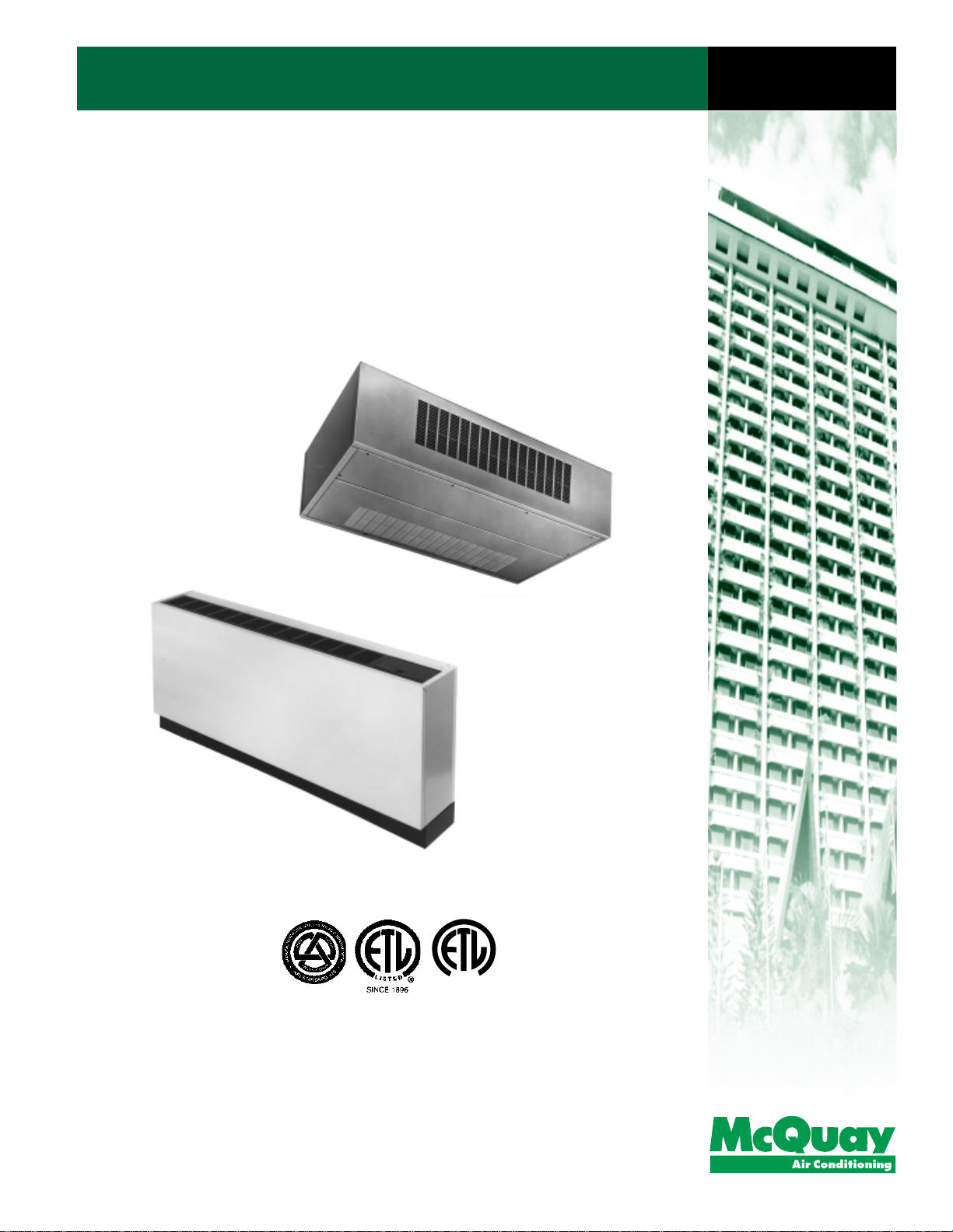
SeasonMaker® ThinLine Fan-coil Units
Type TSH & TSC Horizontal Design
TSS, TPF, TSF & TSB Vertical Design
Catalog
C: 720-12
C
L
I
S
E
T
Ratings Certified by the
Air Conditioning & Refrigeration Institute
D
®
®
Page 2

Page 3
Contents
Computer fan-coil selection ......................................... 2
Design features
TSH & TSC ceiling units ........................................ 5 - 6
TSS, TPF, TSF & TSB floor units ........................... 7 - 8
Optional features and accessories .............................. 9 - 10
Control Systems ........................................................... 11
Unit selection ................................................................ 13
Capacity data ............................................................... 14 - 21
TSH & TSC ceiling units ........................................ 14 - 18
TSS, TPF, TSF & TSB ............................................ 18 - 21
Dimensional data .......................................................... 22 - 26
TSH & TSC ceiling units ........................................ 22 - 23
TSS, TPF, TSF & TSB floor units ........................... 24 - 27
Shipping weights .......................................................... 28
Engineering guide specifications ................................. 29 - 30
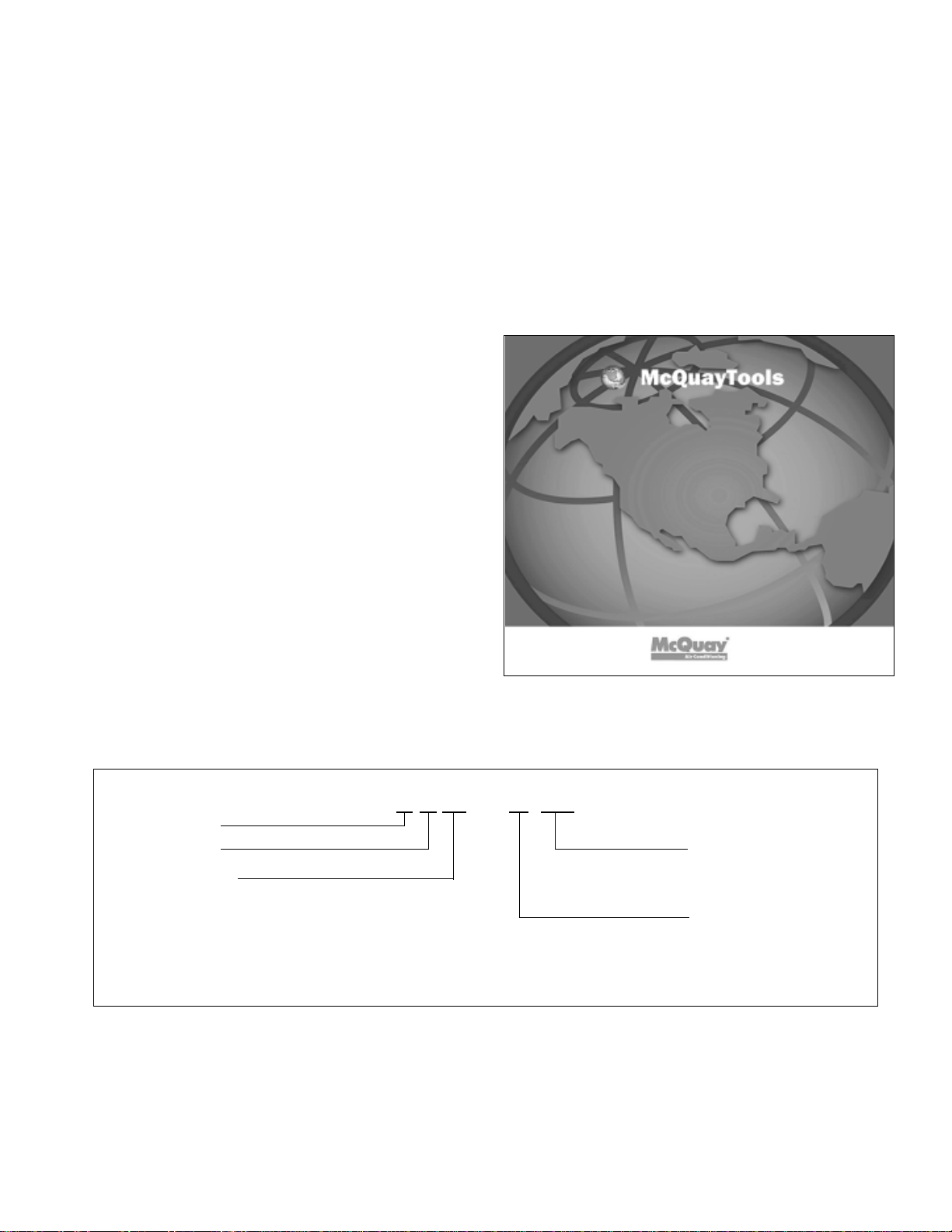
Computer fan-coil selection program
To provide optimal fan coil unit selection, McQuay International
provides McQuayTools™ and SelectTools™ for Fan Coil for
computer fan coil selection capability . These computer programs
aid in the selection of the most economical unit size and coil
option to meet the specification. The program capabilities include
hot and chilled water, hot and chilled water with glycol, electric
heat, supplemental steam heat, and unit external static pressure.
To operate the McQuayTools and SelectTools software the user
needs a computer using Windows® 2000 or higher. McQuay will
provide the software to run McQuayTools and SelectTools for
Fan Coil.
Contact your nearest McQuay representative for a copy of
SelectTools or for a fan coil selection that meets the most
exacting specifications.
Nomenclature
Fan-coil
ThinLine
Type of Unit
SF = Floor Cabinet Unit, Flat Top
SB = Floor Basic Unit
SH = Ceiling Hideaway Unit
SC = Ceiling Cabinet Unit
SS = Slope Top
PF = Tamper-Proof
“McQuay” and “SeasonMaker” are registered trademarks of McQuay International, Auburn, New York
“Bulletin illustrations cover the appearance of McQuay International products at the time of publication
and we reserve the right to make changes in design and construction at anytime without notice.”
F T SF - 1 S02
Unit Size
Nominal cfm in 100’s
(02 = 200, etc.)
Design Series
©2006 McQuay International. All rights reserved throughout the world.
Catalog 720 / Page 3
Page 4
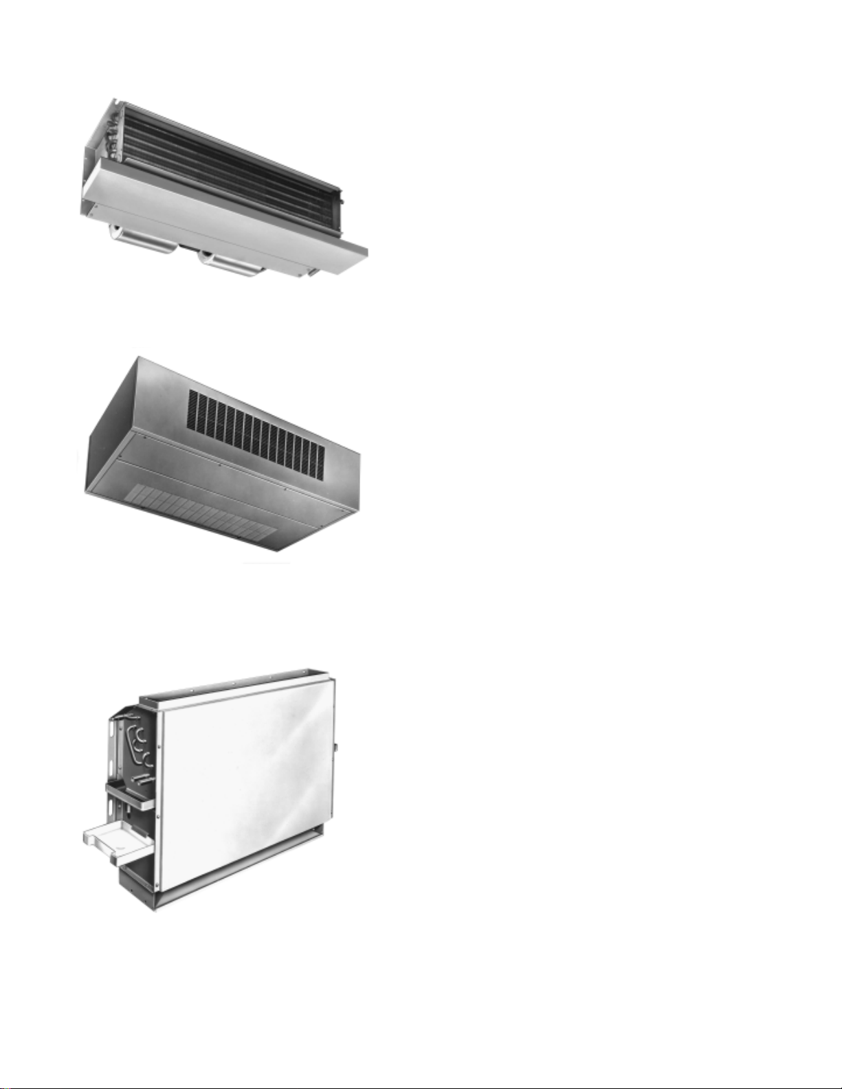
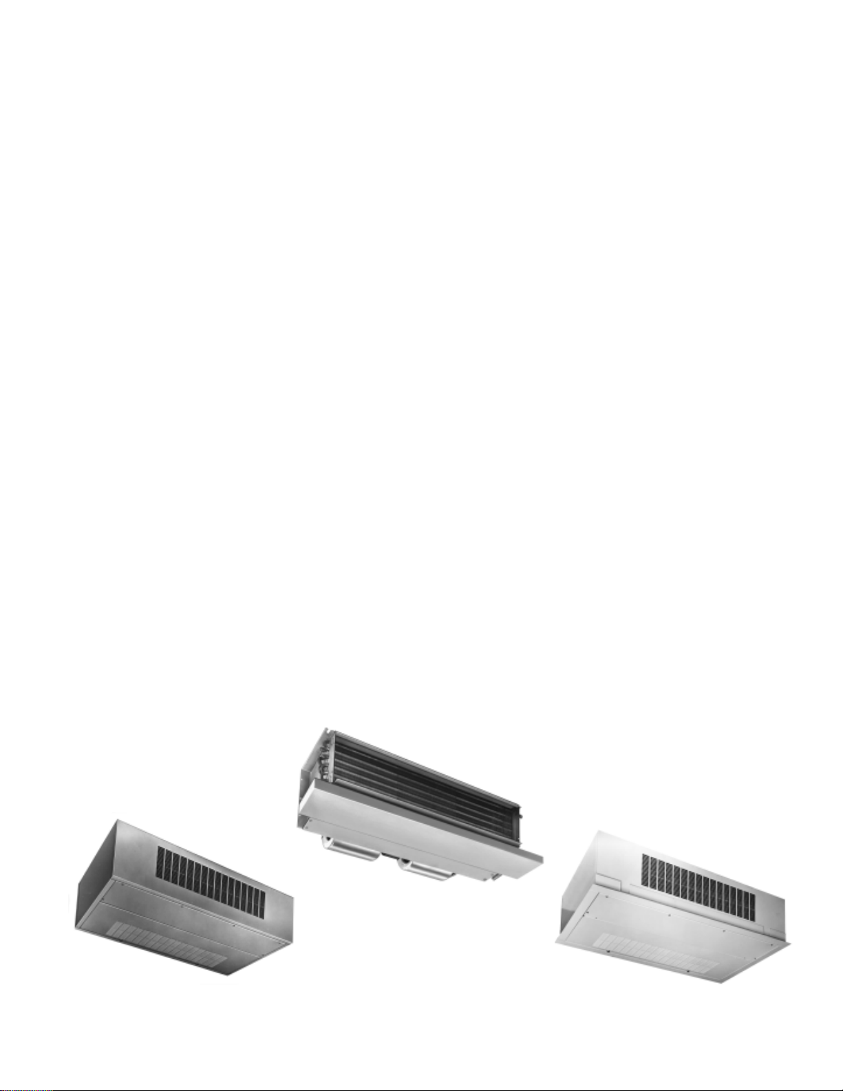
Total fan-coil flexibility
TSH hideaway unit
TSH hideaway unit
The TSH hideaway unit is designed for fully concealed installation in areas where a ceiling enclosure is furnished by others.
Unit features include:
•6 unit sizes from 300 to 1200 cfm.
• Heavy-gauge galvanized steel base casing.
• Standard or high capacity cooling coil.
• Quiet, 3-speed permanent split capacitor motor(s).
• High performance, forward curved centrifugal fan wheels.
• Rigid, self-locking fan deck with split design, die-formed
fan housings for exceptional serviceability.
• Single power location for field wiring connections in unit electrical raceway.
• ARI certified performance.
• ETL and CETL safety agency approval listing.
TSC ceiling unit
The TSC ceiling unit is designed for exposed or recessed ceiling applications. An optional trim flange ceiling frame allows
installation with the TSC hinged bottom panel flush with the
ceiling. The unit includes all of the features listed above for the
TSH unit plus the following:
TSC ceiling unit; exposed cabinet
TSB basic unit; (Top discharge shown)
•6 unit sizes from 300 to 1200 cfm.
• Heavy 18 gauge steel decorative cabinet with stamped discharge grille.
• Attractive Antique Ivory electrostatically applied, baked-on
finish.
• Hinged bottom panel for total accessibility to the unit, controls and filter.
• Stamped return air grille in bottom access panel or back
return duct opening.
• Optional telescoping trim flange ceiling frame to accommodate any ceiling type.
• Cabinet design permits complete removal of the basic unit
for installation in steps coinciding with the various trades.
TSB basic unit
The TSB basic unit is designed for fully concealed or fully recessed applications. The unit can be installed in a custom enclosure or behind a McQuay wall plate. Decorative wall plates
include stamped return air grilles and access door. They are
available with or without stamped discharge grille. Wall plates
are finished with an attractive Antique Ivory electrostatically
applied, baked-on finish. TSB basic unit features include:
•7 unit sizes form 200 to 1200 cfm.
• Heavy-gauge galvanized steel basic cabinet.
• Standard or low flow cooling coil.
• Quiet, 3-speed permanent split capacitor motor.
• High performance forward curved centrifugal fan wheels.
• Split design fan housings or single-piece fan housings with
separate inlets for exceptional serviceability.
• Single power location for field wiring connections in unit electrical box.
• ARI certified performance.
• ETL and CETL safety agency approval listing.
Page 4 / Catalog 720
Page 5

Total fan-coil flexibility
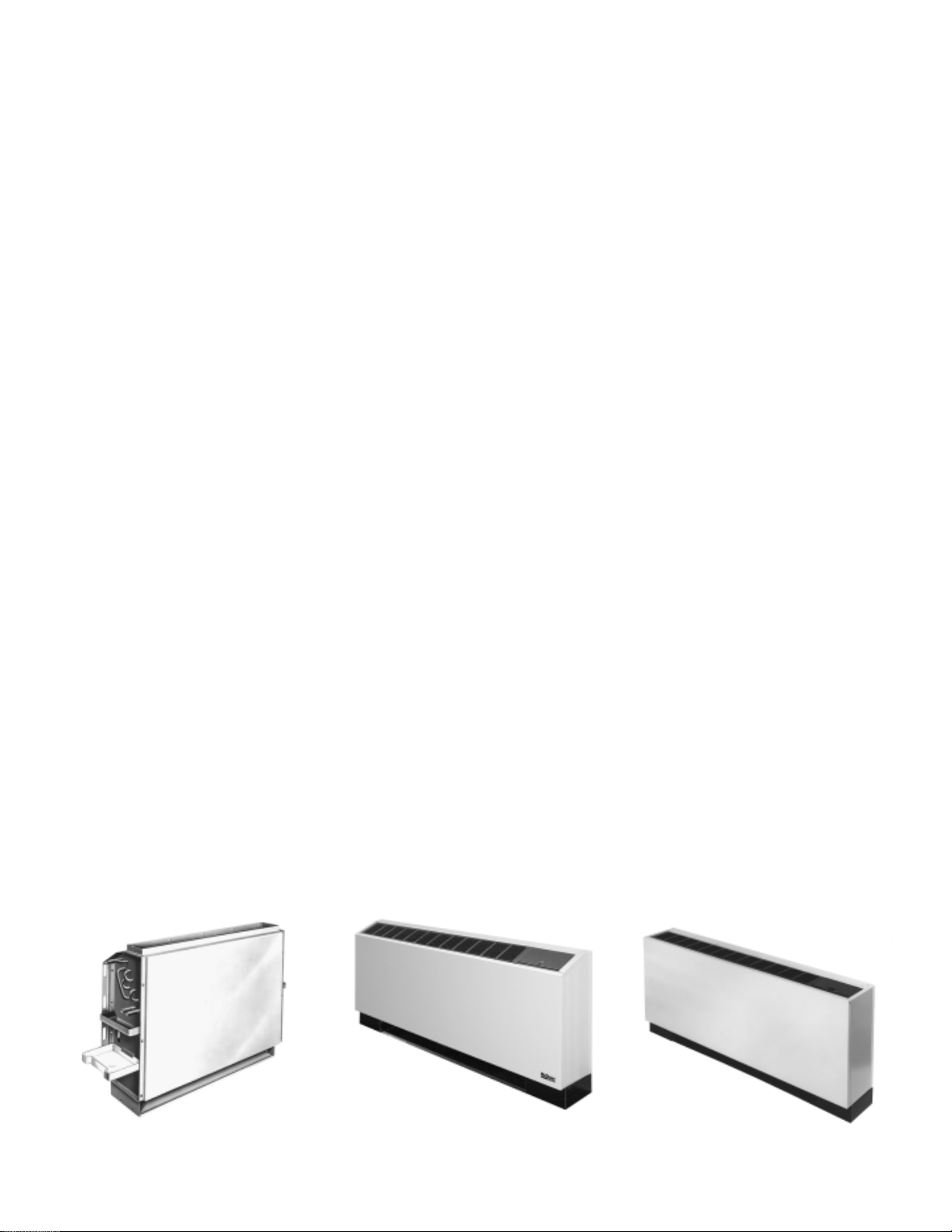
TPF, TSF flat top floor unit
TSF floor unit
The TSF floor unit is designed for use in different installations
as a floor console most frequently installed below a window
for draft free performance or as a wall hung console. The TSF
unit is provided with a flat top discharge. The standard discharge grille is made of a heavy gauge steel. The unit includes
all of the features listed for the TSB unit incorporated in an
attractive cabinet painted with electrostatically applied, bakedon, Antique Ivory finish.
TPF floor unit-Tamper Proof
The TPF floor unit is designed for use as a floor console unit,
as the floor console units above. The TPF unit is standard with
a 16 gauge front panel, tamper-proof screws and locking access doors.
TSS floor unit
The TSS floor unit is designed for use as a floor console unit,
as the TSF unit and is provided with a slope top discharge
grille made of heavy gauge steel. The standard slope top discharge grille directs the air into the room and not into the curtains.
TSS, slope top floor unit
McQuay SeasonMaker® ThinLine fan-coil units
ARI certification, ETL & CETL listing
McQuay ThinLine fan-coil units are tested and rated in accordance with Air Conditioning and Refrigeration Institute (ARI)
Standard 440 and certified in accordance with the ARI certification program. ARI certification assures you full rated performance and offers confidence in unit selection.
ThinLine fan-coil units are listed by ETL and CETL as complying with nationally recognized safety standards for fan-coil
air conditioning units.
Ratings Certified by the
Air Conditioning &
Refrigeration Institute
C
L
I
D
S
E
T
®
Catalog 720 / Page 5
Page 6
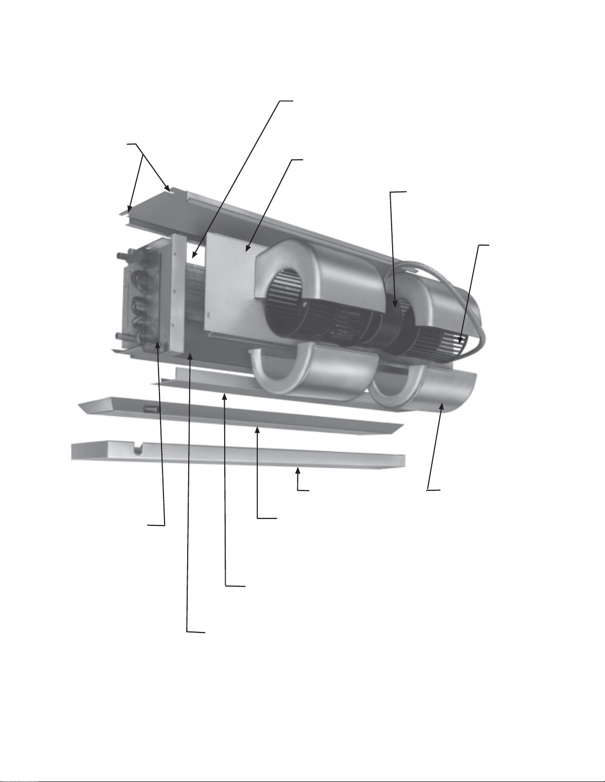
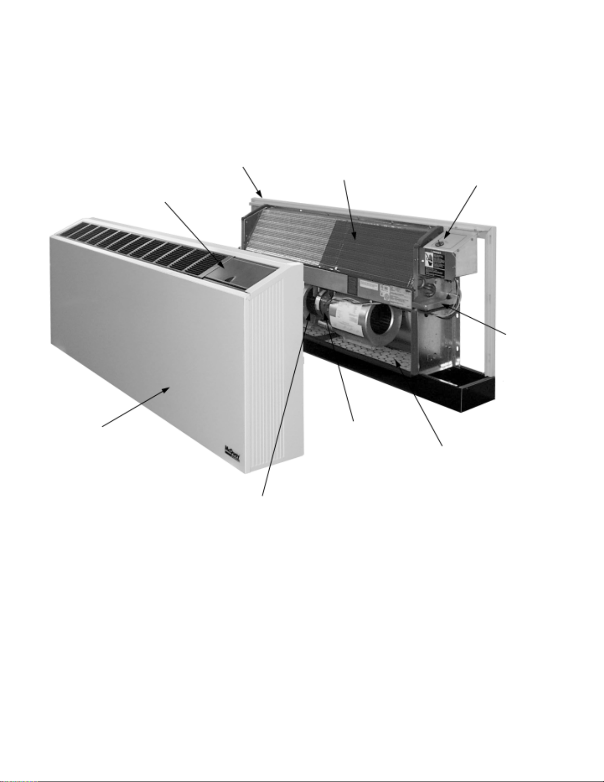
Design features — TSH & TSC ceiling units
Staggered tube coil
with manual air vent
Full size
mounting
slots
for quick
installation
Heavy-gauge galvanized
steel construction for
corrosion resistance
Efficient 3-speed
PSC motor
Fan wheel
Field wiring connection
location (both ends)
Page 6 / Catalog 720
Outer drain pan
Primary drain pan
Electrical raceway
access cover
Electrical raceway
A Complete Line of Ceiling
Fan-coils For Optional Design Flexibility
Split design fan
housing
for quiet air
delivery and
exceptional
service access
Page 7
Quality, efficiency & reliability built into every unit
Coils
Standard and optional high capacity cooling coils are available
with manual air vents for all unit sizes. Optional water heating
and steam coils are available for 4-pipe systems. Field installed
automatic air vents are optional for water cooling coils.
Coils are constructed of seamless copper tubes with headers and aluminum fins. Full depth collars, drawn in the fin stock,
provide accurate control of fin spacing and completely cover
the copper tubes to lengthen coil life. Tubes are mechanically
expanded into the fins for a permanent primary to secondary
surface bond, assuring maximum heat transfer efficiency.
The vertical position of the coil assures rapid condensate
drainage to provide even airflow and full rated capacity at all
conditions.
Motors
Tap wound, three-speed, permanent split capacitor motors are
standard for TSH and TSC units. Motors have sleeve bearings
with oilers, inherent thermal overload protection and automatic
reset. Motors are resiliently mounted to assure quiet, vibrationfree operation and are easily removed.
Fan Wheels
All fan wheels are forward curved, double width, double inlet,
centrifugal type and are statically and dynamically balanced
for smooth, quiet operation.
Fan Housings
Split design fan housings allow quick service of fans and
motors.
Fan Deck
Heavy-gauge continuous galvanized steel rigidly supports
motors, fan assembly, and fan housings as a single unit. The
fan deck is self-locking to the basic chassis and is easily removed for service.
Casing and Cabinet
All units are constructed of heavy gauge steel for long life and
durability. TSC units and optional trim flange ceiling frames are
finished with an electrostatically applied, baked-on Antique Ivory
paint.
Single Power Location
All electrical components of the TSH and TSC units are factory
wired to an electric raceway accessible from the bottom of the
unit. All field wiring connections can be made at the electrical
raceway. Electric heaters, depending on amperage, may require more than one field circuit, all of which can be brought to
the raceway.
Speed Controller
A three-speed switch with off position is available for all sizes.
The speed switch must be field mounted in a 2 x 4 x 2
electrical box by others.
1
⁄2" deep
Controls Systems
A wide variety of two- and four-pipe control systems are available with wall mounted thermostats or combination thermostat/speed switches (see page 10).
Drain Pans
The galvanized steel drain pan with copper connection is insulated on the external surface with fire rated closed cell foam.
The drain pan extends under the entire coil and coil connections. An optional galvanized steel secondary drain pan provides complete condensate drainage from valve package
components.
Filter
TSC units have as standard a 1" throwaway filter. The filter is
easily removable through the bottom access panel. For TSH
units a filter is supplied only with the optional return
air plenum.
TSC Ceiling Unit
TSH Hideaway Unit
TSC Ceiling Unit with
Optional Trim Flange
Catalog 720 / Page 7
Page 8
Design features — TSS, TPF, TSF & TSB floor units
Heavy-gauge galvanized
steel construction for
corrosion resistance
Staggered tube coil
Control panel
access door
Temperature control pad
and speed switch
Wrap-around front panel
designed for easy removal
and easy access to all
components
Primary
drain pan
3-speed permanent
split capacitor motor
Filter is easily
removed
through
return air
opening.
Forward curved
fan(s)
High Performance Coils and Motors
Page 8 / Catalog 720
For Exceptional Energy Economy
Page 9
Quiet, dependable, trouble-free performance
Coils
Standard and optional low flow cooling coils are available with
manual air vents for all unit sizes. Optional water heating and
steam coils are available for 4-pipe systems. Field installed automatic air vents are optional for water cooling coils.
Coils are constructed of seamless copper tubes and headers with aluminum fins. Full depth collars, drawn in the fin stock,
provide accurate control of fin spacing and completely cover
the copper tubes to lengthen coil life. Tubes are mechanically
expanded into the fins for a permanent primary to secondary
surface bond, assuring maximum heat transfer efficiency.
The position of the coil assures rapid condensate drainage
to provide even airflow and full rated capacity at all conditions.
Motors
Tap wound, three-speed, permanent split capacitor motors are
standard for TSS, TPF, TSF and TSB units. Motors have sleeve
or ball bearings with oilers, inherent thermal overload protection with an automatic reset. Motors are resiliently mounted to
assure quiet, vibration-free operation and are easily removed.
Fan Wheels
All fan wheels are forward curved, double width, double inlet,
centrifugal type and are statically and dynamically balanced
for smooth, quiet operation.
Fan Housings
Split design fan housings or single-piece fan housings with
separate inlets offer exceptional serviceability.
Fan Deck
Heavy-gauge continuous galvanized steel rigidly supports
motors, fan assembly and fan housings as a single unit.
Casing and Cabinet
All units are constructed of heavy-gauge steel for long life and
durability. TSS sizes S02 through S06 are provided with
Hi-impact plastic sides. TSS sizes S08 through S12 are
provided with metal sides. TSS, TPF, TSF units and TSB wall
plates are finished with an electrostatically applied, baked-on
Antique Ivory paint. TPF units have 16 gauge front panel and
locking access door.
Discharge Grille
TSS, TPF and TSF units are furnished with a stamped metal
discharge grille. Matching access door offers a distinctive appearance that complements any room decor.
Single Power Location
All electrical components of the TSS, TPF, TSF and TSB units
are factory wired to a single electrical box on the unit. All field
wiring connections can be made at the electrical box. Electric
heaters, depending on amperage, may require more than one
field circuit, all of which can be brought to the electrical box.
Speed Controller
A three-speed switch with off position is provided for all unit
sizes. The speed switch is available unit mounted or for field
installation in a wall mounted 2 x 4 x 2
box by others.
1
⁄2 inch deep electrical
Controls Systems
A wide variety of two- and four-pipe control systems are available with unit mounted or remote thermostats. Unit mounted
controls are provided with an access door, 3-speed fan with
off switch, and optional temperature control knob.
Drain Pans
The galvanized steel primary drain pan is provided with copper
connections, and is insulated on the external surface with fire
rated closed cell foam. The primary drain pan extends under
the entire coil and coil connections. An injection molded secondary drain pan provides complete condensate drainage from
valve package components. The secondary drain pan rotates
o
180
to accommodate field piping.
Filter
TPF, TSF and TSB units have as standard a 1⁄2" throwaway filter. The filter is easily removable through the return air toe space
of TPF, TSF units and wall plate return air grille for TSB units.
TSB basic unit
(Top discharge shown)
TSS slope top metal
Floor Unit
TPF, TSF flat top
Floor Unit
Catalog 720 / Page 9
Page 10
Optional features and accessories
Optional Coils
In addition to the standard cooling coil, an optional low flow
water coil is available for TSS, TPF, TSF and TSB floor units for
use in a two-pipe system. A standard capacity coil or a high
capacity coil is available for TSH and TSC ceiling units for use
in two-pipe systems. A separate one-row heating coil can be
factory installed with any of the above coils for four-pipe
systems. A steam coil is also available for installation with the
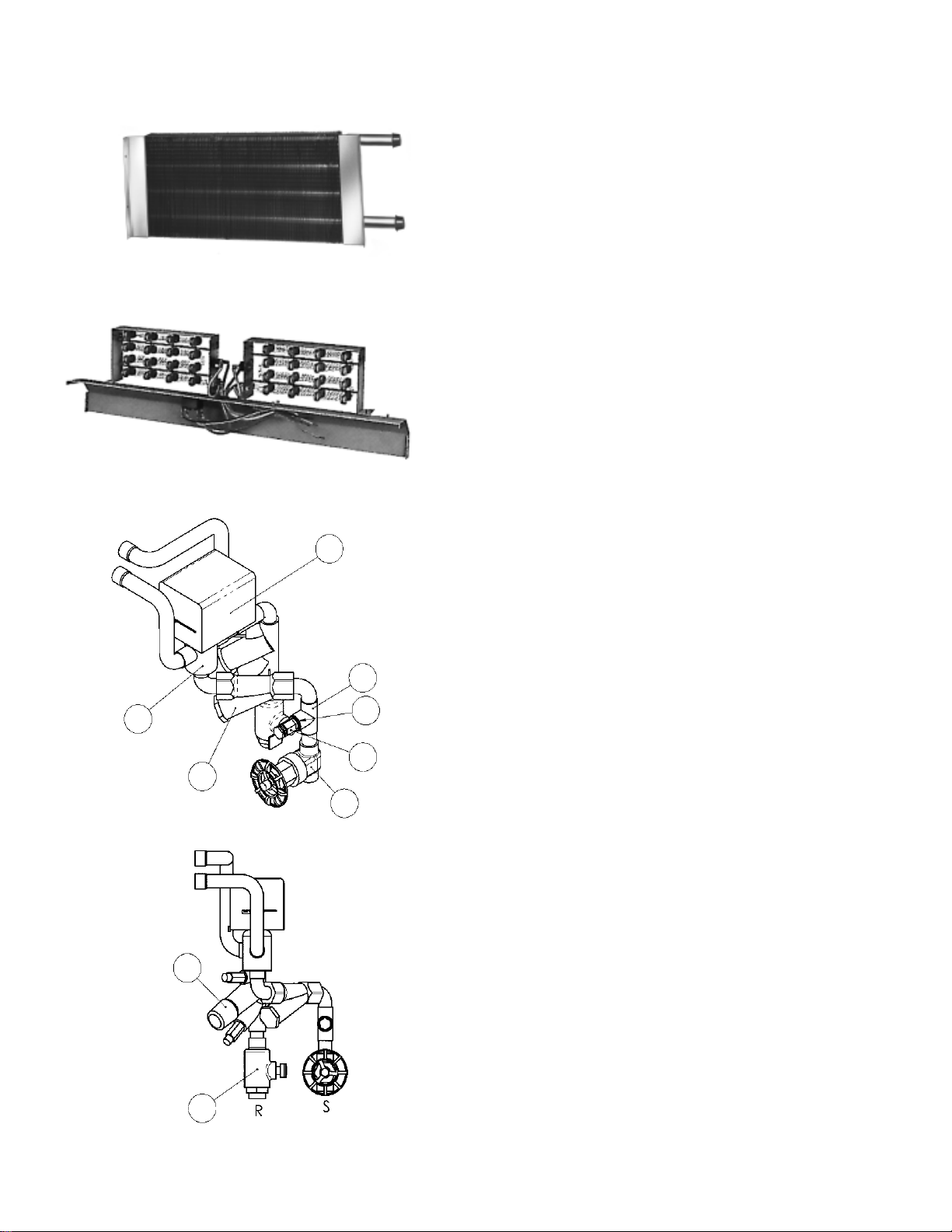
TSH Heating Coil
standard cooling coil. (Manual air vents supplied with water
heating coils must be field mounted.)
Motors
Tap wound, three-speed 115/60/1 or 265/60/1 permanent split
capacitor motors are available on all unit types and sizes. All
motors have sleeve bearings with oilers and inherent thermal
overload protection with automatic reset. Motors are resiliently
mounted to assure quiet, vibration-free operation and are easily
removed for service.
TSH Electric Heater
Valve Body
1
Electric Heat
Electric heat is offered in a wide variety of sizes and voltages.
Each is equipped with an automatic thermal overload switch.
Electric
1
Valve Actuator
Electric heaters can be used for supplementary between-season heating when chilled water is being supplied to the system, or for year-round electric heat.
Return Plenum (TSH Units Only)
A galvanized steel plenum section is available to enclose the
motor and fans. It facilitates making the return air connection
to the unit without interfering with the piping for the unit sup-
6
7
8
5
Supply
4
3
ply, return or drain connections. It is equipped with a 1" throwaway filter holding frame with side or bottom filter access. A
3
/4" duct collar offers easy field duct connections. The plenum
is available factory mounted or as a field mounted kit. The filter
frame and bottom panel can be interchanged for back or bottom return air.
Valve Packages
Two-way and three-way electric valves are available with hand
valves for factory or field mounting opposite hand on all units.
When valve packages are supplied, a secondary drain pan is
also supplied to assure positive drainage of condensate from
valves and piping manifolds (unit types TSS, TPF, TSF and TSB
have a secondary drain pan as standard). Basic package includes electric valve with hand valves . Basic package
with P/T plugs includes above with pressure/temperature taps
. Deluxe package includes all the above plus a strainer
and a flow control device . See Table 1 on page 11 for a
brief description of control systems.
Deluxe Valve Packages
Page 10 / Catalog 720
2
Page 11

Wall Plates (TSB units only)
Decorative wall plates have rounded corners and an Antique
Ivory finish for an attractive appearance.
TSB Wall Plate
Ceiling Flange (TSC Units Only)
Optional field installed ceiling flange accommodates acoustic
type ceiling panels in drop ceiling applications and has an Antique Ivory finish.
Fresh Air Damper
A fresh air intake that will provide up to 25% dilution air with
insect air screen and damper blade, can be ordered either
factory installed or as a field installed kit. The kit consists of
an intake with damper blade and insect screen. The damper
may be manually controlled through the return air opening
or with an optional field installed damper motor. If freezing
air temperatures are expected, the damper must be closed
or outside air must be tempered before entering the unit.
TSS/TPF, TSF/TSB Manual Fresh Air Damper
Rear Cabinet Extension
For applications requiring additional cabinet depth, TSS, TPF
and TSF have available a 4" extension kit. Kit is available
for applications where additional depth is necessary for piping or electrical routing. This kit
duct or outside air plenum.
is not designed to be an air
TSC Unit Shown with Ceiling Flange
Fresh Air Wall Intake Box
Fabricated of aluminum with weep holes and a double set of
louvers in series to prevent moisture draw-through.
TSS/TPF, TSF/TSB Wall Box
Leveling Legs (TSF, TPF, TSS Units Only)
Field installed kits are available with 0 to 1" adjustment for positive leveling of floor-mounted units.
Vertical ThinLine 4" Cabinet Rear Extension
TSS, TPF and TSF Leveling Legs
Catalog 720 / Page 11
Page 12

Thermostats
Wall-mounted thermostats for all application requirements are
available as either thermostats only or combination thermostat
and three-speed switch. Unit mounted thermostats are available for TSF, TPF, TSS and TSB units.
Wall mounted three-speed fan switch and thermostats
Control Systems
Table 1. Electric valve package kits
System Fan Control ➀
Two-Pipe Manual Motorized 2-way or on supply line.
Valve Cycle. (Constant Fan) 3-way. Normally closed. Manual. Unit
(Water Cooling Factory or mounted on control plate
or Heating) Field installed or wall mounted on
Two-Pipe
Valve Cycle. None
With Manual Motorized 2-way or
Electric Heat. (Constant Fan) 3-way. Normally closed.
(Water Cooling Factory or Manual. Unit
and Electric Field installed. mounted on control plate Unit or wall mounted
Heating) ➂ or wall mounted on heating/cooling, SPDT.
Four-Pipe Motorized 2-way or Unit or wall mounted,
Valve Cycle Manual 3-way. Normally closed. None DPDT. Neutral dead-
(Water Cooling (Constant Fan) Factory or band for sequenced
and Heating) Field installed. heating/cooling.
Two-Pipe
Valve Cycle
With Intermediate Factory or
Heat Field installed.
Manual
(Constant Fan)
Control Valve Changeover Control
Type ➁ and Location
Automatic.
Field installed
subbase of thermostat.
subbase of thermostat.
Motorized 2-way or
3-way. Normally closed.
Two automatic Changeovers
(ACO's) required on supply line
to provide ACO and lock out
electric heater when hot water
is available.
Thermostat Type
Unit or wall mounted
heating/cooling, SPDT.
Unit or wall mounted.
DPDT. Neutral dead-
band for sequenced
heating/cooling.
Unit or wall mounted,
DPDT. Neutral dead-
band for sequenced
heating/cooling.
NOTES: ➀ A three-speed fan switch is supplied on all vertical units.
➁ Valve packages are factory mounted or field installed.
➂ Available for supplementary between-season electric heating when chilled water is in the system or for year-round full electric heat.
Page 12 / Catalog 720
Page 13

Unit selection
Selection of unit type
General
The achievement of an efficient fan-coil system is dependent upon accurate system design and proper equipment
selection. Variations, limitations and control of fan-coil systems, design conditions and design load calculations are
not described in detail in this catalog. More detailed information may be found in the ASHRAE Guide. This catalog
contains ARI certified ratings and application ratings for
ThinLine SeasonMaker fan-coil units from which the design
engineer can make initial unit selections to meet the requirements of the system.
The mechanical system designer must select the unit
types best suited to the overall system before the actual
unit sizes can be determined. The factors that generally influence this decision are intended building usage, building
layout, architectural and aesthetic values, economics, geographical location, and type of maintenance service available. The general results may be a mixture of various unit
types within a given system. McQuay International manufactures a fan-coil unit to meet your every need including
ThinLine, HiLine and Large Capacity models.
Basic design data
Prior to selecting the individual unit sizes, the design engineer must fix or determine the following factors:
1. Inside and outside wet and dry bulb design temperatures.
2. Method of introducing the ventilation air.
3. Wet and dry bulb temperatures of the air mixture enter-
ing the unit coil.
4. Total and sensible heat gains and losses of the area to be
served.
5. Properties of the heating and cooling medium.
6. Available electric power service.
7. Any special design requirements of the building or sys-
tem.
culating the peak load requirements due to unusually high
occupancy or severe climatic conditions and with fan operating at high speed. Ordinary day to day cooling and heating requirements are then achieved at low and medium
speeds.
Ventilation requirements should be considered along with
heating and cooling capacity to determine the proper unit
size. Outside fresh air must be tempered before entering the
unit if freezing conditions are expected.
Cooling coil requirements
Having checked the minimum unit size to meet the ventilation requirement, the unit size is generally selected on the
basis of matching the sensible cooling capacity of the unit
with the calculated requirements when operating at high
speed.
Coil Types
Standard and low flow coil types are available for all TSF
and TSB floor unit sizes. Standard and high capacity coil
types are available for all TSH and TSC ceiling unit sizes to
permit unit selections for optimum performance.
• Standard coils are designed to meet both the cooling and
heating requirements in a typical system.
• Low flow coils are designed to meet both the normal cool-
ing and heating requirements while operating with reduced
gpm and correspondingly higher water temperature rises.
Their use is enhanced by the lower first cost of both riser
piping and pump, plus lower overall fan-coil unit and water
pump operating cost.
• High capacity coils are designed to meet cooling and
heating loads that exceed typical system requirements
for ceiling units.
Selection of unit size
The capacity ratings presented in this catalog are provided
for initial unit selection only. Unit size selection should be
determined by using the SelectTools for Fan-coil computer
selection program. Water cooling and heating capacities, unit
air flow, static pressure, electric heat, and glycol solutions
are all incorporated into the program to provide the best
possible selection. Consult your McQuay representative for
a selection tailored to your application.
Unit sizes for the ideal system should be selected by cal-
Heating requirements
Heating requirements for two-pipe systems are generally met
by employing the same water flow rate as cooling and adjusting the entering hot water temperature to obtain a matching unit heat output at low fan speed. Four-pipe systems are
generally designed by specifying the flow rate through the
separate heating coil to meet the required heat load with the
fan operating at low speed.
Electric heaters are available for primary year-round heating or intermediate between-seasons heat loads for twopipe systems when chilled water is in the system.
Catalog 720 / Page 13
Page 14

TSH & TSC Series horizontal units
ARI approved standard ratings - ceiling units
Table 2. Standard coil water cooling capacity ratings ➀
TSH Hideaway Units TSC Ceiling Units
Unit
Size Total Sensible
S03 8,100 6,800 1.7 3.7 5,800 4,600 1.2 2.0
S04 11,900 10,100 2.5 8.0 10,900 9,100 2.2 6.5
S06 19,100 15,200 4.0 3.0 17,100 13,000 3.4 2.4
S08 22,100 17,600 4.6 3.9 19,900 15,200 3.9 2.8
S10 29,000 23,500 6.2 11.5 26,500 20,300 5.3 8.8
S12 38,300 29,700 7.8 21.6 34,500 25,300 6.9 17.2
NOTES:
➀ Rated in accordance with ARI Standard 440. Cooling capacities based on 80
temperature rise and high fan speed with standard 115/60/1 motor. See tables 10 and 11 for air volume capacities.
➁ For cooling coil capacity ratings at conditions other than those listed refer to the SelectTools for Fan-coil computer selection program or consult
your McQuay representative.
Cooling Capacity ➁
(BTUH) (BTUH)
Water Water
Flow P.D.
(GPM) (FT. W.C.)
Table 3. High capacity coil water cooling capacity ratings ➀
TSH Hideaway Units TSC Ceiling Units
Unit
Size Total Sensible
S03 10,200 7,700 2.1 6.3 7,300 5,400 1.5 3.6
S04 15,100 11,000 3.2 4.5 14,000 10,100 2.8 3.6
S06 24,200 17,500 5.0 8.0 21,800 15,400 4.4 5.7
S08 28,000 20,000 5.8 10.4 24,700 17,400 5.1 8.3
S10 37,800 26,700 7.7 14.7 35,700 24,700 7.2 12.3
S12 43,200 30,200 8.6 21.6 39,400 26,800 7.8 17.6
NOTES:
➀ Rated in accordance with ARI Standard 440. Cooling capacities based on 80oF DB/67oF WB entering air, 45oF entering water, 10oF water
temperature rise and high fan speed with standard 115/60/1 motor. See tables 10 and 11 for air volume capacities.
➁ For cooling coil capacity ratings at conditions other than those listed refer to the SelectTools for Fan-coil computer selection program or consult
your McQuay representative.
Cooling Capacity ➁
(BTUH) (BTUH)
Water Water
Flow P.D.
(GPM) (FT. W.C.)
Cooling Capacity ➁
TOTAL SENSIBLE
BTUH BTUH
o
F DB/67oF WB entering air, 45oF entering water, 10oF water
Cooling Capacity ➁
Total Ssnsible
(BTUH) (BTUH)
Water Water
Flow P.D.
(GPM) (FT. W.C.)
Water Water
Flow P.D.
(GPM) (FT. W.C.)
Water heating coil ratings - ceiling units
Table 4. Standard coil water heating capacity ratings ➀
TSH Hideaway Units TSC Ceiling Units
Unit
Size Sensible
S03 16,600 1.7 3.7 13,200 1.2 2.0
S04 22,500 2.5 8.0 19,900 2.2 6.5
S06 36,800 4.0 3.0 31,500 3.4 2.4
S08 42,800 4.5 3.8 37,500 3.9 2.8
S10 58,700 6.2 11.5 50,200 5.3 8.8
S12 72,100 7.8 21.6 59,500 6.9 17.2
➀ Water heating coils at 70oF DB entering air, 140oF entering water and high fan speed with standard 115/60/1 motor. See tables 10 and 11 for air
volume capacities.
➁ For heating coil capacity ratings at conditions other than those listed refer to the SelectTools for Fan-coil computer selection program or consult
your McQuay representative.
Heating Capacity ➁
(BTUH)
Water Water
Flow P.D.
(GPM) (FT. W.C.)
Page 14 / Catalog 720
Heating Capacity ➁
Sensible
(BTUH)
Water Water
Flow P.D.
(GPM) (FT. W.C.)
Page 15

TSH & TSC Series horizontal units
Table 5. High capacity coil water heating capacity ratings ➀
TSH Hideaway Units TSC Ceiling Units
Unit
Size Ssnsible
S03 18,600 2.1 6.3 14,800 1.5 3.6
S04 28,100 3.2 4.5 24,400 2.8 3.6
S06 41,600 5.0 8.0 35,600 4.4 5.7
S08 49,400 5.8 10.4 43,800 5.1 8.3
S10 68,800 7.7 14.7 58,800 7.2 12.3
S12 75,700 8.6 21.6 61,600 7.8 17.6
➀ Water heating coils at 70oF DB entering air, 140oF entering water and high fan speed with standard 115/60/1 motor. See tables 10 and 11 for air
volume capacities.
➁ For heating coil capacity ratings at conditions other than those listed refer to the SelectTools for Fan-coil computer selection program or consult
your McQuay representative.
Heating Capacity ➁
(BTUH)
Water Water
Flow P.D.
(GPM) (FT. W.C.)
Table 6. Standard coil water heating capacity ratings ➀
TSH Hideaway Units TSC Ceiling Units
Unit
Size Sensible
S03 27,272 1.86 5.88 23,177 1.58 4.18
S04 36,189 2.47 10.61 32,095 2.19 8.3
S06 60,155 4.1 2.15 51,283 3.5 1.73
S08 70,391 4.8 2.91 61,519 4.2 2.13
S10 95,483 6.51 8.78 82,518 5.63 6.61
S12 115,984 7.91 16.28 94,829 6.47 11.25
➀ Water heating coils at 70oF DB entering air, 180oF entering water, 30oF water temperature drop, and high fan speed with standard 115/60/1 motor.
See tables 10 and 11 for air volume capacities.
➁ For heating coil capacity ratings at conditions other than those listed refer to the SelectTools for Fan-coil computer selection program or consult
your McQuay representative.
Heating Capacity ➁
(BTUH)
Water Water
Flow P.D.
(GPM) (FT. W.C.)
Heating Capacity ➁
Sensible
(BTUH)
Heating Capacity ➁
Sensible
(BTUH)
Water Water
Flow P.D.
(GPM) (FT. W.C.)
Water Water
Flow P.D.
(GPM) (FT. W.C.)
Table 7. High capcity coil water heating capacity ratings ➀
TSH Hideaway Units TSC Ceiling Units
Unit
Size Sensible
S03 29,660 2.02 5.02 24,627 1.68 4.67
S04 44,400 3.03 3.24 38,600 2.63 2.57
S06 64,852 4.42 4.63 55,299 3.77 3.26
S08 77,477 5.28 6.27 68,605 4.68 5.13
S10 108,772 7.42 10.1 91,712 6.26 7.05
S12 120,325 8.21 12.33 95,417 6.51 7.91
➀ Water heating coils at 70oF DB entering air, 180oF entering water, 30oF water temperature drop, and high fan speed with standard 115/60/1 motor.
See tables 10 and 11 for air volume capacities.
➁ For heating coil capacity ratings at conditions other than those listed refer to the SelectTools for Fan-coil computer selection program or consult
your McQuay representative.
Heating Capacity ➁
(BTUH)
Water Water
Flow P.D.
(GPM) (FT. W.C.)
Heating Capacity ➁
Sensible
(BTUH)
Water Water
Flow P.D.
(GPM) (FT. W.C.)
Catalog 720 / Page 15
Page 16

TSH & TSC Series horizontal units
Table 8. Separate 1-row heating coil capacity ratings ➀
TSH Hideaway Units TSC Ceiling Units
Unit
Size Sensible
S03 12,300 0.8 1.9 12,300 0.8 1.9
S04 16,800 1.1 3.8 16,500 1.0 3.1
S06 22,200 1.5 1.7 18,000 1.2 0.8
S08 23,100 1.6 1.8 21,800 1.5 1.4
S10 36,100 2.4 3.9 31,800 2.1 2.9
S12 46,900 3.2 8.0 46,100 3.1 7.6
➀ Water heating coils at 70oF DB entering air, 180oF entering water, 30oF water temperature drop and high fan speed with standard 115/60/1 motor.
See tables 10 and 11 for air volume capacities.
➁ For heating coil capacity ratings at conditions other than those listed refer to the SelectTools for Fan-coil computer selection program or consult
your McQuay representative.
Heating Capacity ➁
(BTUH)
Water Water
Flow P.D.
(GPM) (FT. W.C.)
Steam coil ratings – ceiling units
Table 9. Separate 1-row steam coil capacity ratings ➀
TSH Hideaway Units TSC Ceiling Units
Unit
Size
S03 20,300 84.6 62 21.0 20,300 84.6 62 21.0
S04 28,300 117.9 65 29.3 27,900 116.3 64 28.8
S06 36,100 150.4 54 37.4 31,000 129.2 51 32.1
S08 50,000 208.3 57 51.8 48,100 200.4 58 49.8
S10 65,100 271.3 53 67.4 61,300 255.4 57 63.4
S12 71,400 297.5 51 73.9 70,400 293.3 55 72.9
➀ Steam coil capacity ratings based on 60oF DB entering air temperature, 2 psig steam pressure and high fan speed with standard 115/60/1
➁ For steam coil capacity ratings at conditions other than those listed, use the steam heating coil conversions found on page 20.
➂ Equivalent Direct Radiation.
Heating Cap. Air Temp.
Sensible EDR ➂
(BTUH)
motor. See tables 10 and 11 for air volume capacities.
Rise
o
F
Condensate
LB/HR.
Heating Capacity ➁
Sensible
(BTUH)
Heat. Cap. ➁ Air Temp.
Sensible EDR ➂
(BTUH)
Water Water
Flow P.D.
(GPM) (FT. W.C.)
Rise
o
F
Condensate
LB/HR.
Air volume capacity data – ceiling units – Standard Coil
Table 10. Air volume versus external static pressure – Standard motors, high speed operation (cfm)
External Static Pressure (inches of water)
Unit TSH Unit Wc" TSH With Plenum TSC Unit Wc"
Size .00 .05 .10 .15 .20 .25 .30 .00 .05 .10 .15 .20 .25 .30 .00 .05 .10 .15 .20 .25 .30
S03 390 360 340 290 200 170 - 340 290 200 170 110 - - 350 300 250 210 160 - -
S04 520 510 500 480 460 450 430 500 480 460 450 430 410 390 480 460 450 430 420 400 390
S06 700 680 670 650 610 570 510 670 650 610 570 510 460 400 640 610 570 540 500 470 430
S08 880 860 830 800 760 710 670 830 800 760 710 670 620 580 790 750 710 680 640 610 570
S10 1300 1270 1220 1180 1120 1060 960 1220 1180 1120 1060 960 900 800 1160 1110 1060 1000 950 900 850
S12 1480 1440 1390 1340 1280 1210 1140 1390 1340 1280 1210 1140 1060 980 1190 1140 1090 1040 990 940 890
Note: Based on 115/60/1 electric service, standard unit options, and dry coils.
Page 16 / Catalog 720
Page 17

TSH & TSC Series horizontal units
Air volume capacity data – ceiling units – Hi Capacity Coil
Table 11. Air volume versus external static pressure – Standard motors, high speed operation (cfm)
External Static Pressure (inches of water)
UNIT TSH Unit Wc" TSH With Plenum TSC Unit Wc"
SIZE .00 .05 .10 .15 .20 .25 .30 .00 .05 .10 .15 .20 .25 .30 .00 .05 .10 .15 .20 .25 .30
S03 370 340 310 270 170 150 - 310 270 170 150 130 100 - 320 280 240 190 150 110 -
S04 510 500 480 460 450 430 410 480 460 450 430 410 390 360 460 450 430 420 400 380 370
S06 710 690 670 640 590 550 500 670 640 590 550 500 460 400 650 610 570 540 500 460 420
S08 870 850 820 800 770 740 690 820 800 770 740 690 640 590 740 710 660 630 590 530 490
S10 1290 1240 1200 1150 1080 1020 950 1200 1150 1080 1020 930 880 820 1130 1070 1000 880 810 750 690
S12 1400 1320 1260 1200 1120 1050 950 1260 1200 1120 1050 950 900 850 1160 1100 1050 990 930 870 810
Note: Based on 115/60/1 electric service, standard unit options, and dry coils.
Motor Data – ceiling units
Table 12. Motor data – TSH & TSC units
Unit Size
Motor S03 S04 S06 S08 S10 S12
Speed Amps Watts RPM Amps Watts RPM Amps Watts RPM Amps Watts RPM Amps Watts RPM Amps Watts RPM
High 0.70 75 1080 1.4 185 1200 1.6 190 1070 2.30 250 1280 4.30 450 1350 3.80 395 1160
Medium 0.40 47 820 1.00 110 880 1.00 104 810 1.60 160 1030 2.30 209 1060 3.00 347 1020
Low 0.30 34 600 0.60 58 530 0.70 67 520 0.90 90 920 1.50 137 600 1.90 195 650
High 0.34 80 1080 0.50 135 1200 0.70 170 1070 1.00 220 1280 1.30 290 1360 1.40 305 1160
Medium 0.30 66 800 1.40 88 880 0.43 74 815 0.63 131 925 1.00 220 1050 1.30 260 1000
Low 0.29 60 600 0.25 45 530 0.32 50 520 0.36 73 630 0.90 180 600 0.70 145 650
115/60/1
265/60/1
Electric heat data – ceiling units
Table 13. Electric resistance heater capacities – TSH & TSC units
Single Stage Heaters – Electrical Service
Unit 120/60/1 208/60/1 240/60/1 265/60/1
Size Watts BTUH Amps Watts BTUH Amps Watts BTUH Amps Watts BTUH Amps
S03 2000 6826 16.6 2000 6826 9.6 2000 6826 8.3 2000 6826 7.2
S04 2000 6826 16.6 2000 6826 9.6 2000 6826 8.3 2000 6826 7.2
S06 ---4000 13652 19.2 4000 13652 16.7 4000 13652 14.4
S08 ---4000 13652 19.2 4000 13652 16.7 4000 13652 14.4
S10
S12
1000 3413 8.3 1000 3413 4.8 1000 3413 4.2 1000 3413 3.6
---3000 10239 14.4 3000 10239 12.5 3000 10239 10.8
1000 3413 8.3 1000 3413 4.8 1000 3413 4.2 1000 3413 3.6
---3000 10239 14.4 3000 10239 12.5 3000 10239 10.8
2000 6826 16.6 2000 6826 9.6 2000 6826 8.3 2000 6826 7.2
---6000 20478 28.8 6000 20478 25.0 6000 20478 21.7
2000 6826 16.6 2000 6826 9.6 2000 6826 8.3 2000 6826 7.2
---6000 20478 28.8 6000 20478 25.0 6000 20478 21.7
---4000 13652 19.2 4000 13652 16.7 4000 13642 14.4
---6000 20478 28.8 6000 20478 25.0 6000 20478 21.7
---4000 13652 19.2 4000 13652 16.7 4000 13652 14.4
---6000 20478 28.8 6000 20478 25.0 6000 20478 21.7
Catalog 720 / Page 17
Page 18

TSF & TSB Series floor units
ARI approved standard ratings - floor units
Table 14.
TSS, TPF, TSF & TSB units ➀
Standard coil water cooling capacity ratings
Table 15.
Low flow coil water cooling capacity ratings
TSS, TPF, TSF & TSB units ➀
Unit
Size Total Sensible
S02 5,600 4,400 1.2 1.4
S03 8,000 6,100 1.7 1.1
S04 10,900 8,800 2.3 1.6
S06 15,600 11,700 3.1 6.4
S08 20,100 15,900 4.1 6.5
S10 28,300 21,600 6.0 6.6
S12 30,100 24,600 6.4 11.3
NOTES:
➀ Rated in accordance with ARI Standard 440. Cooling capacities based on 80
➁ For cooling coil capacity ratings at conditions other than those listed refer to the SelectTools for Fan-coil computer selection program or consult
Cooling Capacity ➁
(BTUH) (BTUH)
temperature rise and high fan speed with standard 115/60/1 motor. See table 21 & 22 for air volume capacities.
your McQuay representative.
Water Water
Flow P.D.
(GPM) (FT. W.C.)
Unit
Size Total Sensible
S02 6,800 5,200 1.4 2.7
S03 9,200 6,600 1.9 1.3
S04 13,500 10,200 2.7 3.1
S06 17,900 13,700 3.7 7.9
S08 29,800 19,800 6.1 12.9
S10 33,400 25,000 6.9 10.6
S12 35,600 25,900 7.7 13.2
o
F DB/67oF WB entering air, 45oF entering water, 10oF water
Cooling Capacity ➁
(BTUH) (BTUH)
Water Water
Flow P.D.
(GPM) (FT. W.C.)
Water heating coil ratings - floor units
Table 16.
TSS, TPF, TSF & TSB units ➀
Unit Capacity ➁ Water Water
Size (Sensible Flow P.D.
S02 10,600 1.2 1.4
S03 15,400 1.7 1.1
S04 21,900 2.3 1.6
S06 27,300 3.1 6.4
S08 35,300 4.1 6.5
S10 50,700 6.0 6.6
S12 55,700 6.4 11.3
NOTES:
➀ Water heating coils at 70o F DB entering air, 140o F entering water and high fan speed with standard 115/60/1motor. See table 21 & 22 for air
volume capacities.
➁ For heating coil capacity ratings at conditions other than those listed refer to the SelectTools for Fan-coil computer selection program or consult
your McQuay representative.
Standard coil water heating capacity ratings
Heating
BTUH) (GPM) (FT. W.C.)
Table 17.
Low flow coil water heating capacity ratings
TSS, TPF, TSF & TSB units ➀
Unit Capacity➁ Water Water
Size (Sensible Flow P.D.
S02 11,600 1.4 2.7
S03 17,100 1.9 1.3
S04 24,700 2.7 3.1
S06 31,000 3.7 7.9
S08 45,500 6.1 12.9
S10 55,100 6.9 10.6
S12 60,800 7.7 13.2
Heating
BTUH) (GPM) (FT. W.C.)
Page 18 / Catalog 720
Page 19

TSF & TSB Series floor units
Table 18. Water heating capacity ratings
TSS, TPF, TSF & TSB units ➀
Standard Coil Water Heating Capacity Ratings High Capacity Coil Water Heating Capacity Ratings
Unit Heating Heating
Size Capacity➁ Water Flow Water P.D. Capacity➁ Water Flow Water P.D.
(Sensible BTUH) (GPM) (FT.W.C.) (Sensible BTUH) (GPM) (FT.W.C.)
S02 17,005 1.16 1.25 18,189 1.24 2.07
S03 24,798 1.69 1.03 27,183 1.85 1.19
S04 35,720 2.44 1.7 39,421 2.69 2.93
S06 43,671 2.98 5.68 48,789 3.33 6.24
S08 55,233 3.77 5.3 69,596 4.75 7.82
S10 79,854 5.45 5.28 84,637 5.77 7.34
S12 88,384 6.03 9.69 94,191 6.43 9.12
NOTES:
➀ Water heating coils at 70o F DB entering air, 180o F entering water, 30o F water temperature drop, and high fan speed
with standard 115/60/1 motor. See table 21 & 22 for air volume capacities.
➁ For heating coil capacity ratings at conditions other than those listed refer to the SelectTools for Fan-coil computer
selection program or consult your McQuay representative.
Table 19. Separate 1-row coil water heating capacity
ratings TSS, TPF, TSF & TSB units ➀
Unit Capacity➁ Water Water
Size (Sensible Flow P.D.
S02 11,400 0.8 1.8
S03 15,100 1.0 3.4
S04 20,500 1.4 6.1
S06 28,400 1.9 12.6
S08 38,900 2.6 7.2
S10 48,500 3.3 1.9
S12 55,300 3.8 2.5
NOTES:
➀ Water heating coils at 70o F DB entering air, 180o F entering water, 30o F water temperature drop and high fan speed with standard 115/60/1
motor. See table 21 & 22 for air volume capacities.
➁ For heating coil capacity ratings at conditions other than those listed refer to the SelectTools for Fan-coil computer selection program or consult
your McQuay representative.
Heating
BTUH) (GPM) (FT. W.C.)
Catalog 720 / Page 19
Page 20

TSF & TSB Series floor units
Steam coil ratings - floor units
Table 20. Standard steam coil heating capacity
ratings TSS, TPF, TSF & TSB units ➀
Unit
Size
S02 13.2 55.2 54 13.7
S03 16.9 70.8 56 17.5
S04 23.8 99.5 56 17.5
S06 32.7 136.8 56 33.8
S08 54.1 226.0 62 55.9
S10 65.1 274.6 65 67.9
S12 74.8 312.9 59 77.4
Heating Air
Capacity➁
(Sensible Rise
BTUH) (oF)
EDR ➂
Temp.
Condensate
(LB/HR)
Air volume capacity data – floor units
Standard Coil
Table 21. Air volume versus external static pressure
TSS, TPF, TSF & TSB units (cfm)
Unit TSF Standard Unit Wc"
Size .00 .05 .10 .15 .20
S02 240 200 160 120 80
S03 280 240 200 150 100
S04 430 370 320 250 180
S06 560 490 410 330 260
S08 770 710 650 590 520
S10 1080 1020 970 920 870
S12 1250 1210 1170 1130 1100
NOTES:
➀ Steam coil capacity ratings based on 60
psig steam pressure and high fan speed with standard 115/60/1 motor.
➁ For steam coil capacity ratings at conditions other than those listed, use the
steam heating coil conversion factors found on page 21.
➂ Equivalent Direct Radiation.
o
F DB entering air temperature, 2
Air volume capacity data – floor units
High Capacity Coil
Table 22. Air volume versus external static pressure
TSS, TPF, TSF & TSB units (cfm)
Unit TSF HiCap Unit Wc"
Size .00 .05 .10 .15 .20
S02 230 180 150 110 60
S03 290 240 200 120 70
S04 480 410 360 300 220
S06 670 640 580 530 480
S08 700 640 580 520 450
S10 1070 1020 980 930 880
S12 1220 1190 1150 1110 1080
NOTES:
➀ Air volumes based on 115/60/1 electric service, standard unit options and dry coils.
➁ The SelectTools for Fan-coil computer selection program will not allow cooling coil face velocities below 90 ft./min. Some of the airflows found on
the chart are included for heating only or ventilating applications.
Motor data – floor units – Standard Coil
Table 23. Motor data – TSS, TPF, TSF & TSB units
Unit Size
Motor
Speed
High 0.60 82 1050 0.60 75 1100 0.90 105 1000 2.00 212 1050 1.90 190 850 3.10 328 1000 8.00 356 1270
Medium 0.40 41 845 0.42 48 950 0.60 70 830 1.70 83 800 1.50 169 790 1.65 180 840 3.40 235 940
Low 0.30 35 600 0.36 36 700 0.55 63 600 1.65 75 600 1.40 155 570 1.60 162 650 2.30 175 650
High 0.40 57 1050 0.40 78 1100 0.48 86 1000 0.50 120 1050 0.80 180 850 1.40 731 1000 3.00 330 1270
Medium 0.30 54 845 0.31 60 990 0.44 85 905 0.43 86 1005 0.60 160 800 0.65 175 800 2.25 235 1000
Low 0.20 53 600 0.29 58 890 0.42 82 725 0.39 80 845 0.55 150 700 0.60 150 650 1.63 165 800
S02 S03 S04 S06 S08 S10 S12
Amps Watts RPM Amps Watts RPM Amps Watts RPM Amps Watts RPM Amps Watts RPM Amps Watts RPM Amps Watts RPM
115/60/1 PSC Motor
265/60/1 PSC Motor
Page 20 / Catalog 720
Page 21

TSF & TSB Series floor units
Electric heat data – floor units
Table 24. Electric resistance heater capacities – TSS, TPF, TSF & TSB units
Unit
Size
S02
S03 1000 3413 8.3 1000 3413 4.8 750 2560 3.1 1000 3413 3.6
S04 2000 6826 16.6 2000 6826 4.8 1500 5120 6.3 2000 6826 7.2
S06 2000 6826 16.6 2000 6826 9.6 1500 5120 6.3 2000 6828 7.2
S08 ---4000 13652 19.2 3000 10239 12.5 4000 13652 14.4
S10
S12
*240V Heaters are derated 265V heaters.
Watts BTUH Amps Watts BTUH Amps Watts BTUH Amps Watts BTUH Amps
750 2560 6.3 750 2560 3.6 560 1911 2.3 750 2560 2.7
1000 3413 8.3 1000 3413 4.8 750 2560 3.1 1000 3413 3.6
1500 5120 12.5 1500 5120 7.2 1125 3840 4.7 1500 5120 5.4
750 2560 6.3 750 2560 3.6 560 1911 2.3 750 2560 2.7
1500 5120 12.5 1500 5120 7.2 1125 3840 4.7 1500 5120 5.4
2000 6826 16.6 2000 6826 9.6 1500 5120 6.3 2000 6826 7.2
1000 3413 8.3 1000 3413 4.8 750 2560 3.1 1000 3413 3.6
1500 5120 12.5 1500 5120 7.2 1125 3840 4.7 1500 5120 5.4
3000 10239 25.0 3000 10239 14.4 2250 7679 9.4 3000 10239 10.8
1000 3413 8.3 1000 3413 4.8 750 2560 3.1 1000 3413 3.6
1500 5120 12.5 1500 5120 7.2 1125 3840 4.7 1500 5120 5.4
3000 10239 25.0 3000 10239 14.4 2250 7679 9.4 3000 10239 10.8
120/60/1 208/60/1 240/60/1* 265/60/1
---3000 10239 14.4 2250 7679 9.4 3000 10239 10.8
---6000 20478 28.8 4500 15360 18.8 6000 20478 21.7
---3000 10239 14.4 2250 7679 9.4 3000 10239 10.8
---4000 13652 19.2 3000 10239 12.5 4000 13652 14.4
---6000 20478 28.8 4500 15360 18.8 6000 20478 21.7
---3000 10239 14.4 2250 7679 9.4 3000 10239 10.8
---4000 13652 19.2 3000 10239 12.5 4000 13652 14.4
---6000 20478 28.8 4500 15360 18.8 6000 20478 21.7
Single Stage Heaters – Electrical Service
Steam heating coil conversion factors
Table 25. For ratings at other than base conditions, multiple coil capacity by proper conversion factor
Steam
Pressure
0 212.0 970.3 1.34 1.27 1.21 1.15 1.08 1.02 0.96 0.90 0.83 0.77
2 218.5 966.0 1.38 1.31 1.25 1.19 1.13 1.06 1.00 0.94 0.87 .081
5 227.1 960.6 1.43 1.37 1.31 1.24 1.18 1.12 1.06 0.99 0.93 0.87
10 239.4 952.6 1.51 1.45 1.38 1.32 1.26 1.20 1.13 1.07 1.01 0.94
15 249.7 945.6 1.57 1.51 1.45 1.38 1.32 1.26 1.20 1.13 1.07 1.01
20 258.8 939.6 1.63 1.57 1.51 1.44 1.38 1.32 1.25 1.19 1.13 1.06
25 266.8 934.0 1.68 1.62 1.56 1.50 1.43 1.37 1.31 1.24 1.17 1.12
To determine the capacity at conditions other than 2 PSIG steam and 60oF entering air, multiply the rated capacity by the proper conversion factor.
Steam
Temp.
(SAT.)
Latent
Heat
0102030405060708090
Entering Air Temperature (oF)
Catalog 720 / Page 21
Page 22

Dimensional data – Type TSH Series
hideaway ceiling unit
TSH Unit Return Plenum
Size Filter Size
S03 207⁄8 X 97⁄8 X 1
S04 267⁄8 X 97⁄8 X 1
S06 35
S08 35
S10 437⁄8 X 97⁄8 X 1
S12 597⁄8 X 97⁄8 X 1
7
7
8 X
8 X
97⁄8 X 1
97⁄8 X 1
TSH Unit
Size Cooling Heating
S03 Thru S12
Coil Connection Size
5
⁄8 O.D. SW
LEFT HAND UNIT SHOWN
Hand of unit determined by cooling
connection when facing front of unit.
5
⁄8 O.D. SW
TOP VIEW
OPTIONAL PLENUM SIDE VIEW
(SIDE VIEW)
FRONT VIEW DRAIN CONN. DETAIL
(FRONT VIEW)
TSH Unit
Size A B C D E F G H J K L
S03 201⁄4 19 27 51⁄2 21⁄2 47⁄8 17⁄8 21 22 4 1
S04 26
S06 351⁄4 34 42 51⁄2 21⁄2 47⁄8 17⁄8 36 37 4 1
S08 351⁄4 34 42 51⁄2 21⁄2 47⁄8 17⁄8 36 37 4 1
S10 431⁄4 42 50 5
S12 591⁄4 58 68 61⁄2 31⁄2 57⁄8 27⁄8 60 61 5 2
1
⁄4 25 33 51⁄2 21⁄2 47⁄8 17⁄8 27 28 4 1
1⁄
2
ALL DIMENSIONS APPROXIMATE. CERTIFIED DRAWINGS AVAILABLE ON REQUEST.
Dimensions (inches)
21⁄2 47⁄8 17⁄8 44 45 4 1
Page 22 / Catalog 720
Page 23

Dimensional data – Type TSC Series
cabinet ceiling unit
Front View
Remote 3-Speed
fan switch with off
position
P/N 107112101
Back View
*Coil and drain connections
may not be in line with cabinet
knockouts.
Top View
Note: Caution must be exercised when
units are used with outside air as standard units are insulated on the leaving
air side only. Outside fresh air must be
tempered before entering the unit if freezing conditions are expected.
End View
Detail A
LEFT HAND UNIT SHOWN
Hand of unit determined by cooling coil
connection when facing front of unit.
(side view)
Bottom View
TSC
Unit Size A B D E F G H J K L
S03 43 37 611⁄
S04 43 37 611⁄
S06 52 46 63⁄
S08 52 46 63⁄
S10 78 72 611⁄
S12 78 72 611⁄
16
16
8
8
16
16
Dimensions (inches)
2911⁄
2911⁄
391⁄
391⁄
6411⁄
6411⁄
16
16
4
4
16
16
385⁄
385⁄
475⁄
475⁄
735⁄
735⁄
8
8
8
8
8
8
87⁄
87⁄
83⁄
83⁄
113⁄
113⁄
8
8
8
8
8
8
2411⁄
2411⁄
16
16
2
91⁄
2
91⁄
34 9 34 541⁄
34 9 34 541⁄
58 10 58 801⁄
58 10 58 801⁄
24 451⁄
24 451⁄
TSC
4
4
4
4
4
4
Filter Size
8
267⁄
97⁄
X
8
267⁄
97⁄
X
8
357⁄
97⁄
X
8
357⁄
97⁄
X
8
597⁄
97⁄
X
8
597⁄
97⁄
X
Catalog 720 / Page 23
8
1
X
8
1
X
8
1
X
8
1
X
8
1
X
8
1
X
Page 24

Dimensional data
Type TSF Series flat top cabinet floor unit
LEFT HAND UNIT SHOWN
Hand of unit determined by cooling coil
connection when facing front of unit.
Control Box
NOTE: Outside fresh air must be
tempered before entering the unit
if freezing conditions are expected.
*Dimensions may vary for units with
nonstandard valve packages.
TSF Unit Return Air
Size Filter Size (IN.)
S02 73⁄4 X 183⁄4 X 1⁄2
S03 73⁄4 X 243⁄4 X 1⁄2
S04 73⁄4 X 333⁄4 X 1⁄2
S06 73⁄4 X 433⁄4 X 1⁄2
S08 10 X 433⁄4 X 1⁄2
S10 10 X 553⁄4 X 1⁄2
S12 10 X 553⁄4 X 1⁄2
TSH Unit
Size Cooling Heating
S02 Thru S12
Unit
Size A B C D F G H J K M N P R S T U
TSF-S02 37 25 91⁄4 27⁄8 217⁄8 193⁄4 157⁄8 107⁄8 57⁄8 411⁄16 81⁄16 31⁄2 10 21⁄2 79⁄16 415⁄16
TSF-S03 43 25 91⁄4 27⁄8 277⁄8 193⁄4 157⁄8 107⁄8 57⁄8 411⁄16 81⁄16 31⁄2 10 21⁄2 79⁄16 415⁄16
TSF-S04 51 25 91⁄4 27⁄8 367⁄8 193⁄4 157⁄8 107⁄8 57⁄8 411⁄16 81⁄16 31⁄2 16 21⁄2 71⁄16 411⁄16
TSF-S06 61 25 91⁄4 27⁄8 467⁄8 193⁄4 157⁄8 107⁄8 57⁄8 411⁄16 81⁄16 31⁄2 16 21⁄2 71⁄16 411⁄16
TSF-S08 61 28 121⁄4 57⁄8 467⁄8 213⁄8 17 12 6 77⁄16 1013⁄16 31⁄2 16 3 71⁄16 411⁄16
TSF-S10 75 28 121⁄4 57⁄8 587⁄8 213⁄8 17 12 6 77⁄16 1013⁄16 31⁄2 16 3 81⁄16 57⁄16
TSF-S12 75 28 121⁄4 57⁄8 587⁄8 213⁄8 17 12 6 77⁄16 1013⁄16 31⁄2 16 3 81⁄16 57⁄16
Page 24 / Catalog 720
ALL DIMENSIONS APPROXIMATE. CERTIFIED DRAWINGS AVAILABLE ON REQUEST.
Unit Dimensions (inches)
Coil Connection Size
5
⁄8 O.D. SW
5
⁄8 O.D. SW
Page 25

Dimensional data
Type TSS Series slope top cabinet floor unit
SLOPE TOP
WITH METAL
DISCHARGE GRILLE
TSS sizes S04 thru S06 have
hi-impact plastic sides.
S08-S12 have metal sides.
Control Box
NOTE: Outside fresh air must be
tempered before entering the unit
if freezing conditions are expected.
*Dimensions may vary for units with
nonstandard valve packages.
TSS Unit Return Air
Size Filter Size (IN.)
S02 73⁄4 X 183⁄4 X 1⁄2
S03 73⁄4 X 243⁄4 X 1⁄2
S04 73⁄4 X 333⁄4 X 1⁄2
S06 73⁄4 X 433⁄4 X 1⁄2
S08 10 X 433⁄4 X 1⁄2
S10 10 X 553⁄4 X 1⁄2
S12 10 X 553⁄4 X 1⁄2
TSS Unit
Size Cooling Heating
S02 Thru S12
Unit
Size A B C D F G H J K M N P R S T U
TSS-S02 37 25 91⁄4 251⁄2 217⁄8 193⁄4 157⁄8 107⁄8 57⁄8 411⁄16 81⁄16 31⁄2 10 21⁄2 79⁄16 415⁄16
TSS-S03 43 25 91⁄4 251⁄2 277⁄8 193⁄4 157⁄8 107⁄8 57⁄8 411⁄16 81⁄16 31⁄2 10 21⁄2 79⁄16 415⁄16
TSS-S04 51 25 91⁄4 251⁄2 367⁄8 193⁄4 157⁄8 107⁄8 57⁄8 411⁄16 81⁄16 31⁄2 16 21⁄2 71⁄16 411⁄16
TSS-S06 61 25 91⁄4 251⁄2 467⁄8 193⁄4 157⁄8 107⁄8 57⁄8 411⁄16 81⁄16 31⁄2 16 21⁄2 71⁄16 411⁄16
TSS-S08 61 28 121⁄4 281⁄2 467⁄8 213⁄8 17 12 6 77⁄16 1013⁄16 31⁄2 16 3 71⁄16 411⁄16
TSS-S10 75 28 121⁄4 281⁄2 587⁄8 213⁄8 17 12 6 77⁄16 1013⁄16 31⁄2 16 3 81⁄16 57⁄16
TSS-S12 75 28 121⁄4 281⁄2 587⁄8 213⁄8 17 12 6 77⁄16 1013⁄16 31⁄2 16 3 81⁄16 57⁄16
ALL DIMENSIONS APPROXIMATE. CERTIFIED DRAWINGS AVAILABLE ON REQUEST.
Unit Dimensions (inches)
Coil Connection Size
5
⁄8 O.D. SW
5
⁄8 O.D. SW
Catalog 720 / Page 25
Page 26

Dimensional data Type TSB
Top View
Series basic floor unit
LEFT HAND UNIT SHOWN
Hand of unit determined by cooling coil
connection when facing front of unit.
D
Optional Front Panel Wall Plate
NOTE: Optional top duct discharge
unit shown. Front discharge units
are also available. Outside fresh air
must be tempered before entering
the unit if freezing conditions are
expected.
B
Control Box
G
C
D
15⁄16"
13
⁄16"
Q
Return Air Opening
5
⁄8"
H
J
K
Front Panel for
Top Discharge is
Optional Front Panel - Wall Plate
Optional Top Duct Discharge - E x D
A
E
T
Front View
3
5
⁄8" (S02 – S06)
3
5
⁄4" (S08 – S12)
1
2
1
⁄2" Filter - Removable Thru Return Air Opening
F
⁄8"
9
⁄16" x 2" Mounting Slots
(3 Each Side)
Back View
5
⁄8"
Optional Unit Mounted
Control Box
Standard Electrical
Junction Box
7*
Optional Back Fresh Air Intake
with Damper and Insect Screen (See Detail)
RV
U
*Dimensions may vary for units with
nonstandard valve packages.
TSB Unit Return Air
Size Filter Size (IN.)
S02 73⁄4 X 183⁄4 X 1⁄2
S03 73⁄4 X 243⁄4 X 1⁄2
S04 73⁄4 X 333⁄4 X 1⁄2
S06 73⁄4 X 433⁄4 X 1⁄2
S08 10 X 433⁄4 X 1⁄2
S10, S12 10 X 553⁄4 X 1⁄2
S10*, S12* (2) 10 X 271⁄4 X 1⁄2
*Filter dimensions on sizes S10 and S12 change when ordered with
a wall plate.
TSB Unit
Size Cooling Heating
S02 Thru S12
Unit
Size A B C D E F G H J K M N P Q R S T U V
TSB-S02 20
TSB-S03 265⁄8 257⁄16 93⁄4 41⁄8 25 217⁄8 193⁄4 157⁄8 1015⁄16 515⁄16 411⁄16 931⁄2 17⁄16 10 21⁄2 73⁄4 81⁄16 41⁄16 363⁄4
TSB-S04 355⁄8 257⁄16 93⁄4 41⁄8 34 367⁄8 193⁄4 157⁄8 1015⁄16 515⁄16 411⁄16 931⁄2 17⁄16 16 21⁄2 71⁄4 79⁄16 313⁄16 453⁄4
TSB-S06 455⁄8 257⁄16 93⁄4 41⁄8 44 467⁄8 193⁄4 157⁄8 1015⁄16 515⁄16 411⁄16 931⁄2 17⁄16 16 21⁄2 71⁄4 79⁄16 313⁄16 553⁄4
TSB-S08 455⁄8 283⁄16 121⁄2 51⁄2 44 467⁄8 213⁄8 17 12 6 77⁄16 113⁄4 31⁄2 116371⁄4 79⁄16 313⁄16 553⁄4
TSB-S10 575⁄8 283⁄16 121⁄2 51⁄2 56 587⁄8 213⁄8 17 12 6 77⁄16 113⁄4 31⁄2 116381⁄4 813⁄16 413⁄16 673⁄4
TSB-S12 575⁄8 283⁄16 121⁄2 51⁄2 56 587⁄8 213⁄8 17 12 6 77⁄16 113⁄4 31⁄2 116381⁄4 813⁄16 413⁄16 673⁄4
5
⁄8 257⁄16 93⁄4 41⁄8 19 217⁄8 193⁄4 157⁄8 1015⁄16 515⁄16 411⁄16 931⁄2 17⁄16 10 21⁄2 73⁄4 81⁄16 41⁄16 303⁄4
ALL DIMENSIONS APPROXIMATE. CERTIFIED DRAWINGS AVAILABLE ON REQUEST.
Unit Dimensions (inches)
Coil Connection Size
5
⁄8 O.D. SW
5
⁄8 O.D. SW
Overall Width
with Drain Pan
Page 27

Wall plate
Wall Plate With Front Discharge
WALL PLATE ARRANGEMENTS
Wall Mounted (Four Side Overlap)
TSB Unit
TSB
Unit Size A C Wall Opening
S02 40 28 253⁄4 X 37
S03 46 28 253⁄4 X 43
S04 55 28 253⁄4 X 52
S06 65 28 253⁄4 X 62
S08 65 31 283⁄4 X 62
S10 Thru
S12
Wall Plate Dimensions Recommended
77 31 28
3
⁄4 X 74
Fresh air wall intake box
For use with Types TSF & TSB units
STYLE
2 BRICK X 2 BRICK 163⁄4 43⁄4 33⁄4
4 BRICK X 2 BRICK 331⁄2 43⁄4 33⁄4
DIMENSIONS (INCHES)
ABC
NOTE:
1. All dimensions in inches.
2. Wall plates for TSB unit sizes S10 and S12 are provided in two sections
split vertically down the center.
ALL DIMENSIONS APPROXIMATE.
CERTIFIED DRAWINGS AVAILABLE ON REQUEST.
Page 28

Secondary drain pan
For use with Type TSF floor Unit and Type TSB Basic Unit
7/8" O.D copper sweat connection
7/8" O.D molded plastic connection suitable for 1/2"
NOTE: Drain pan can be rotated 90 or 180 degrees.
* On sizes S04, and S08 the drain pan is 1/2" smaller. The 8" dimensions become 71⁄2" and the 2" dimensions become 13⁄4".
ALL DIMENSIONS APPROXIMATE. CERTIFIED DRAWINGS AVAILABLE ON REQUEST.
nominal PVC socket elbow or coupling
Shipping weights
Table 28. Approximate shipping weights (lbs.) – TSH and TSC ceiling units
Unit Type
TSH LESS PLENUM 34 40 52 56 78 104
TSH RETURN AIR PLENUM 23 27 31 31 38 52
TSC 102 105 128 130 184 211
NOTE: Approximate shipping weights do not include valve packages, hot water coils, electric heaters or other
options.
S03 S04 S06 S08 S10 S12
Unit Size
Table 29. Approximate shipping weights (lbs.) – TSF and TSB floor units
Unit Type
TSS, TPF, TSF 77 87 105 123 160 182 220
TSB 58 62 80 101 131 151 187
NOTE: Approximate shipping weights do not include valve packages, hot water coils, electric heaters or other options.
S02 S03 S04 S06 S08 S10 S12
Unit Size
Page 29

Engineering guide specifications — ceiling units
Furnish and install where shown on the plans and specifications, McQuay (horizontal hideaway type) (ceiling exposed type)
(ceiling recessed type) ThinLine SeasonMaker fan-coil units. Types, sizes and performance shall be tabulated in the schedule.
Unit performance shall be substantiated by computer generated output data. Each unit shall be ARI certified and consist of
and comply with the following:
Casing and Cabinets
Ceiling hideaway type (TSH) — Basic unit shall consist of a base casing and optional return air plenum fabricated of heavy
gauge galvanized steel with four-sided
shall have a filter frame with one-inch return air duct collar that can be interchanged for back or bottom return air. Plenum shall
be fully insulated to prevent unit sweating and attenuate fan noise.
Ceiling (exposed) (recessed) cabinet type (TSC) — Unit shall consist of basic unit casing enclosed in an attractive heavygauge steel cabinet finished with an electrostatically applied, baked-on Antique Ivory paint. Cabinet shall have a stamped
horizontal discharge grille with return air through the (bottom grille) (rear duct opening) of the unit. Cabinet shall include a
bottom hinged access panel as standard.
Electrical Raceway — Unit shall have an electrical raceway providing a single location for all field wiring connections. All
factory mounted electrical components shall have wire leads terminating in the unit raceway.
Coils — Coils shall have aluminum fins with copper tubes mechanically expanded for a permanent bond. Coils are tested at
320 psig. Water coils shall have a manual air vent. Unit performance shall be as tabulated in the schedule.
Fan assembly — Fans shall be DWDI forward curved, centrifugal type. Fan housing shall be of two-piece construction with a
split fan housing that is easily removed, thus allowing complete service access to the fans and motors.
Motors — Units shall have (115/60/1) (265/60/1) three-speed, sleeve bearing, permanent split capacitor motors with oilers,
inherent thermal overload protection with automatic reset and resilient mounts.
3/4" duct collar for ease of connecting discharge ductwork. Optional return air plenum
Drain pan — Drain pan shall be constructed of 20-gauge galvanized steel, insulated with
Insulation — Ceiling model TSC shall be insulated with 1/2" multi-density glass fiber on the cabinet bottom panel and discharge
transition between coil and discharge opening. Hideaway TSH return air plenum shall be insulated with
fiber.
Filters — Filters shall be throwaway type.
1/4" multi-density closed cell insulation.
1/2" multi-density glass
Optional accessories
Electric heat — Units shall be provided with (120/60/1)(265/60/1) electric heat. Heaters shall be fully protected by a high-limit
thermal cut-out with automatic reset. All electric heat controls are to be unit mounted, wired and enclosed by the unit
manufacturer at the factory. All ceiling models shall have heating elements located on the entering air side of the cooling coil.
Valve packages — Valve packages shall consist of 2-or 3-way motorized valve with gate hand valve on supply and ball hand
valve on return piping, (P/T plugs), (strainer and flow control device). Two-way motorized valve packages shall have bypass
capillary tubes to provide minimal flow to enable automatic changeover aquastats, where required, to sense system water
temperature.
Secondary drain pan — Units with valve packages shall be provided with galvanized steel secondary drain pan to channel
valve package condensate into primary pan.
Speed Control — Units shall have a three-speed switch with integral on/off switch suitable for wall mounting which shall
provide high/medium/low fan speed control.
Page 30

Engineering guide specifications — floor units
Furnish and install where shown on the plans and specifications, McQuay (floor type) (basic type) ThinLine SeasonMaker
fan-coil units. Types, sizes and performance shall be tabulated in the schedule. Unit performance shall be substantiated by
computer generated output data. Each unit shall be ARI certified and consist of and comply with the following:
Casing and cabinets
Flat top floor type (TSF) — Cabinet shall be a vertical console type enclosure fabricated of heavy gauge steel and finished
with a electrostatically applied, baked-on Antique Ivory paint. Cabinet shall include a stamped metal discharge grille in the top
panel and full width electrical and piping end compartments. Units provided with mounted controls shall have a single access
door.
Tamper-proof floor type (TPF) — Cabinet shall be a vertical console type enclosure fabricated of heavy gauge steel and
finished with a electrostatically applied, baked-on Antique Ivory paint. Cabinet shall include a stamped metal discharge grille
in the top panel and full width electrical and piping end compartments. Units provided with mounted controls shall have a
single access door. Unit provides a 16 gauge front panel, tamper-proof screws and locking access doors.
Slope top floor type (TSS) (metal) — Cabinet shall be a vertical console type enclosure fabricated of heavy-gauge steel and
finished with an electrostatically applied, baked on Antique Ivory paint. Side panels of S02 thru S06 will be hi-impact plastic.
The discharge grille shall be made of stamped metal. Units provided with unit mounted controls shall have a single access door.
Basic type (TSB) — Basic unit shall consist of base casing fabricated of heavy-gauge galvanized steel with (top duct) (front
discharge) opening for installation in custom enclosure furnished by contractor.
Basic type with wall plates (TSB) — Basic unit shall consist of base casing fabricated of heavy-gauge galvanized steel with
(top duct) (front) discharge. Wall plates shall be fabricated of 18-gauge steel, finished with an electrostatically applied, bakedon Antique Ivory paint. Wall plates shall include stamped discharge grille, access doors and return air grille.
Electrical box — Unit shall have an electrical box providing a single location for all field wiring connections. All factory
mounted electrical components shall have wire leads terminating in the unit electrical box.
Coils — Coils shall have aluminum fins with copper tubes mechanically expanded for a permanent bond. Coils are tested at
320 psig. Water coils shall have a manual air vent. Coil performance shall be as tabulated in the schedule.
Fan assembly — Fans shall be DWDI forward curved, centrifugal type. Fan housing shall be fabricated of heavy-gauge
galvanized steel and of two-piece construction with a split fan housing that is easily removed, thus allowing complete service
access to the fans and motors.
Motors — Units shall have (115/60/1) (265/60/1) three-speed, sleeve bearing, permanent split capacitor motors with oilers,
inherent thermal overload protection with automatic reset and resilient mounts.
Speed control — TSB/TSF with metal grille: Units shall have a (unit)(wall) mounted three-speed switch with integral on/off
switch which shall provide high/medium/low fan speed control.
Drain pan — Primary drain pan shall be constructed of 20-guage galvanized steel and insulated with closed cell insulation.
Secondary drain pan shall be constructed of injection molded polystyrene and meet UL code 94V-2 for smoke and flame
spread. Secondary drain pan shall be equipped with a drain connection suitable to receive a
Insulation — Cabinet insulation shall be 1/2" multi-density glass fiber.
Filters — Filters shall be throwaway type.
1/2" PVC socket elbow or coupling.
Optional accessories
Electric heat — Units shall be provided with (120/60/1) (265/60/1) electric heat. Heaters shall be fully protected by a high-limit
thermal cut-out with automatic reset. All electric heat controls are to be unit mounted, wired and enclosed by the unit
manufacturer at the factory. Floor and basic models through 600 cfm shall have fully sheathed elements located on the
leaving air side of the cooling coil. Units 800 cfm and greater shall have open type heater elements located on the entering air
side of the cooling coil.
Valve packages — Valve packages shall consist of 2- or 3-way motorized valve with gate hand valve on supply and ball hand
valve on return piping, (P/T plugs), (strainer and flow control device). Two-way motorized valve packages shall have bypass
capillary tubes to provide minimal flow to enable automatic changeover aquastats, where required, to sense system water
temperature.
Fresh air kit — A manual fresh air intake damper shall be provided by the unit manufacturer for (factory) (field) installation. An
electric, damper motor shall be provided by the unit manufacturer for field installation.
Aluminum wall box — An aluminum wall box with two sets of louvers shall be provided by the unit manufacturer for field
installation into the outside wall of the building.
Page 31

Page 32

Warranty
All McQuay equipment is sold pursuant to its standard terms and conditions of sale, including Limited
Product Warranty. Consult your local McQuay Representative for warranty details. Refer to Form
933-43285Y. To find your local McQuay Representative, go to www.mcquay.com.
This document contains the most current product information as of this printing. For the most up-to-date
product information, please go to www.mcquay.com.
Products Manufactured in an ISO Certified Facility.
®
©2005 McQuay International (800) 432-1342 www.mcquay.com Catalog 720 (10/06)
 Loading...