

Page 1
Page 2
TABLE OF CONTENTS
INTRODUCTION
General Description . . . . . . . . . . . . . . . . . . . . . . . . . ...3
Nomenclature . . . . . . . . . . . . . . . . ., . ., . . . . . . . . . ...3
Inspection . . . . . . . . . . . . . . . . . . . . . . . . . . . . . . . . . ...3
INSTALLATION
Handling . ., ., . . . . . . . . . . . . . . ., . . . . . . . . . . . . . ...3
Moving The Unit, ., . .,,..,... . . . . . . . . . . . . . . . ...4
Location .,.....,........,.. ., . ., ., ., . . . . . . . ...4
Clearance Requirements ...,. . . . . . . . . . . . . . . . . ...4
Placing the Unit . ., ..,.,.... , . . . . . . . . . . . . . . . ...4
Vibration isolators,.,...,.,.. . . . . . . . . . . . . . . ...5.6
WATER PIPING
General . . . . . . . . . . . . . . . . . . . . . . ., . . . . . . . . . . . ...6
Evaporator Piping . ., ..,.,.... . .,.,......,....,.6
Evaporator Temperature Limits . ., . . . . . . . . . . . . . ...6
Flow Rate Limits . . . . . . . . . . . . . . . . . . . . . . . . . . . . ...7
Evaporator Pressure Drop Corrections . . . . . . . . . . ...7
Evaporator Pressure Drop Curve.... . ., . . . . . . . . ...7
CONDENSER WATER PIPING . . . . . . . . . . . . . . . . . . ...8
Condenser Temperature Limits . . . . . . . . . . . . . . . . ...8
Condenser Temperature Rise . . . . . . . . . . . . . . . . . ...8
Condenser Flow Rate Limits... . . . . . . . . . . . . . . . ...8
Condenser Water Arrangements . . . . . . . . . . . . . . . ...9
Condenser Pressure Drop Correction ., .,........,.9
Condenser Pressure Drop Curves . ., . . . . . . . . ...9. 10
TYPICAL PIPING DIAGRAMS., . . . . . . . . . . . . . . . . ...11
Water Quality . . . . . . . . . . . . . . . , . ., ., . ., . . . . . ...12
Condenser Water Thermostat .,, . . . . . . . . . . . . . ...12
Flow Switches . . . . . . . . . . . . . . . . . . . . . . . . . . . . . ...12
Relief Valve Piping . . . . . . . . . . . . . . . . . . . . . . . . . ...13
DIMENSIONAL DATA . . . . . . . . . . . . . . . . . . . . .14.15.16
STARTUP&SHUTDOWN
Pre Startup . . . . . . . . . . . . . . . . . . . . . . . . . . . . . . . ...45
Startup . . . . . . . . . . . . . . . . . . . . . . . . .,.,.....,.,.,45
Temporary Shutdown .,,.,... . . . . . . . . . . . . . . . ...45
Extended Shutdown .,,.,.... , . . . . . . . . . . . . . . ...46
Startup After Extended Shutdown ,, ., . . . . . . . . . ...46
SYSTEM MAINTENANCE
General ..,.,..,..,....,.,.. . . . . . . . . . . . . . . ...47
Control Center Service, .,..... . . . . . . . . . . . . . . ...47
Electrical Terminals.,....,.. ., ., . . . . . . . . . . . ...47
Compressor Oil Level, .,....,. . ., ., . . . . . . . . . ...47
Refrigerant Sightglass .,.,.... ., . . . . . . . . . . . . ...48
Lead-Lag . . . . . . . . . . . . . . . . . . . . . ., ., . . . . . . . . ...48
Crankcase Heaters .,, ..,..... . ., . ., ., . ., ..,...48
SYSTEM SERVICE
Filter-driers ., . . . . . . . . . . . . . . . . . . . . . . . . . . . . . ...49
Liquid Line Solenoid Valve.... , . . . . . . . . . . . . . . ...49
Thermostatic Expansion Valve, ...,.,.,. . .,.....,49
Evaporator, . . . . . . . . . . . . . . . . . .,,...,.,,..,.,.,50
Watercooled Condenser,..,.. ., ., ., . . . . . . . . ...50
IN-WARRANTY RETURN MATERIAL PROCEDURE
Compressor . ., .,, . . . . . . . . . . . . . . . . . . . . . . . . . ...50
Components Other Than Compressor . . . . . . . . . . ...51
APPENDIX
STANDARD CONTROLS:
Thermostat, . . . . . . . . . . . . . . . . . ., ..,.,.......,51
Oil Pressure Safety Control ., . ., . ., ., . ., ..,.,.51
Compressor Lockout ., . . . . . . . . . ., . . . . . . . . . ...52
High Pressure Control. .,...... . . . . . . . . . . . . ...52
Low Pressure Control .,.....,. . . . . . . . . . . . . ...52
Freezestat . . . . . . . . . . . . . . . . . . , ., . ., . . . . . . ...52
Compressor Motor Protector . . . . . . . . . . . . . . . ...53
PHYSICAL DATA . . . . . . . . . . . . . . . . . . . . . . . . . ...17.18
Compresor Locations . . . . . . . . . , . . . . . . . . . . . . . ...19
Contactor Designation . . . . . . . . . . . . . . . . . . . . . . ...19
Major Components . . . . . . . . . . . . . . . . . . . . . . . . . ...19
WIRING
Field Wiring, Power...,..,.. . . . . . . . . . . . . . . . ...20
Field Wiring, Control, . . . . . . . . . . . . . . . . . . . . . . . . ..2o
Interlock Wiring . . . . . . . . . . . . . . , . . . . . . . . . . ...20.21
Sequence of Operation . . . . . . . . ., . . . . . . . . ...22.23
Electrical Data . . . . . . . . . . . . . . . . . . . . . . . . . . . . . ...24
Control Center . . . . . . . . . . . . . . . . . . . . . . . . . . . . . ...25
Electrical Legend . . . . . . . . . . . . . . . . . . . . . . . . . . ...26
Power Schematics . . . . . . . . . . . ,. ... . . . . . ..27—33
Control & Safety Schematics . . . . . . . . . . . . . . ...34.35
Thermostat Schematics . . . . . . . . . . . . . . . . . ..36—41
Electrical Schematic Drawing Decision Tables.42—44
Page2/lM377
OPTIONAL CONTROLS:
Part Winding Start, . . . . . . . . . . , . ., . ., ., ..,....53
Phase/VoltageMonitor., . . . . . . . . . . . . . . . . . . ...53
Alarm Bell . . . . . . . . . . . . . . . . . . , . . . . . . . . . . . ...53
Low Source Water, . . . . . . . . . . , . . . . . . . . . . . . ...54
Hot Gas Bypass . . . . . . . . . . . . . . . . . . . . . . . . . ...54
CONTROLS, SETTINGS, & FUNCTIONS. ., . . . . . . ...55
TROUBLESHOOTING CHART,. . . . . . . . . . . . . . . . ...56
PRESSURE TEMPERATURE TABLE . . . . . . . . . . . ...57
—
Page 3
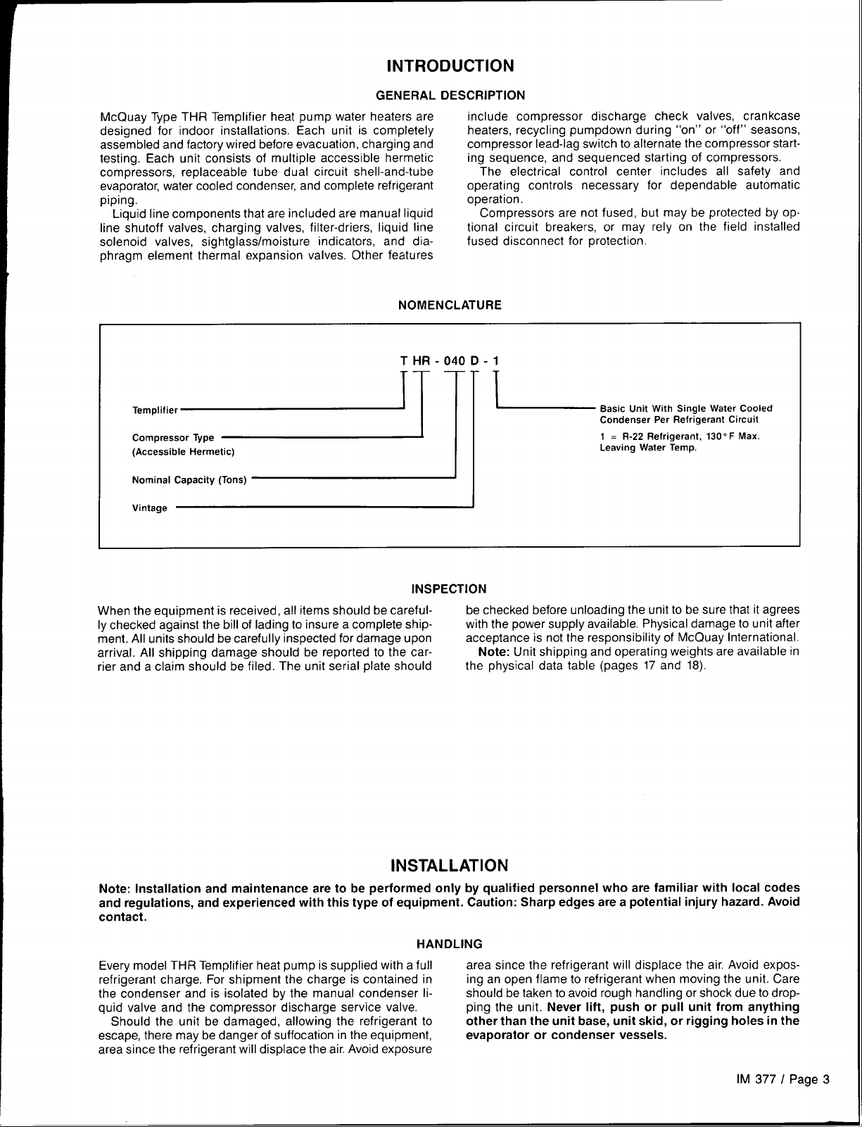
INTRODUCTION
GENERAL
McQuay Type THR Templifier heat pump water heaters are
designed for indoor installations. Each unit is completely
assembled and factory wired before evacuation, charging and
testing. Each unit consists of multiple accessible hermetic
compressors, replaceable tube dual circuit shell-and-tube
evaporator, water cooled condenser, and complete refrigerant
piping.
Liquid line components that are included are manual liquid
line shutoff valves, charging valves, filter-driers, liquid line
solenoid valves, sightglass/moisture indicators, and diaphragm element thermal expansion valves. Other features
NOMENCLATURE
THR-040 D-1
D;::+J
(Accessible Hermetic)
Nominal Capacity (Tons)
DESCRIPTION
include compressor discharge check valves, crankcase
heaters, recycling pumpdown during “on” or “off” seasons,
compressor lead-lag switch to alternate the compressor starting sequence, and sequenced starting of compressors.
The electrical control center includes all safety and
operating controls necessary for dependable automatic
operation.
Compressors are not fused, but may be protected by op-
tional circuit breakers, or may rely on the field installed
fused disconnect for protection.
Basic Unit With Single Water Cooled
Condenser Per Refrigerant Circuit
L
‘1
1 = R-22 Refrigerant, 130” F Max.
Leaving Water Temp.
INSPECTION
When the equipment is received, all items should be careful- be checked before unloading the unit to be sure that it agrees
Iy checked against the bill of lading to insure a complete shipment. All units should be carefully inspected for damage upon
arrival. All shipping damage should be reported to the carrier and a claim should be filed. The unit serial plate should
with the power supply available. Physical damage to unit after
acceptance is not the responsibility of McQuay International.
Note: Unit shipping and operating weights are available in
the physical data table (pages 17 and 18).
INSTALLATION
Note: Installation and maintenance are to be performed only by qualified personnel who are familiar with local codes
and regulations, and experienced with this type of equipment. Caution: Sharp edges are a potential injury hazard. Avoid
contact.
HANDLING
Every model THR Templifier heat pump is supplied with a full area since the refrigerant will displace the air. Avoid exposrefrigerant charge. For shipment the charge is contained in ing an open flame to refrigerant when moving the unit. Care
the condenser and is isolated by the manual condenser li- should be taken to avoid rough handling or shock due to dropquid valve and the compressor discharge service valve. ping the unit.
Should the unit be damaged, allowing the refrigerant to other than the unit base, unit skid, or rigging holes in the
escape, there may be danger of suffocation in the equipment,
area since the refrigerant will displace the air. Avoid exposure
evaporator or condenser vessels.
Never lift, push or pull unit from anything
IM 377 I Page 3
Page 4
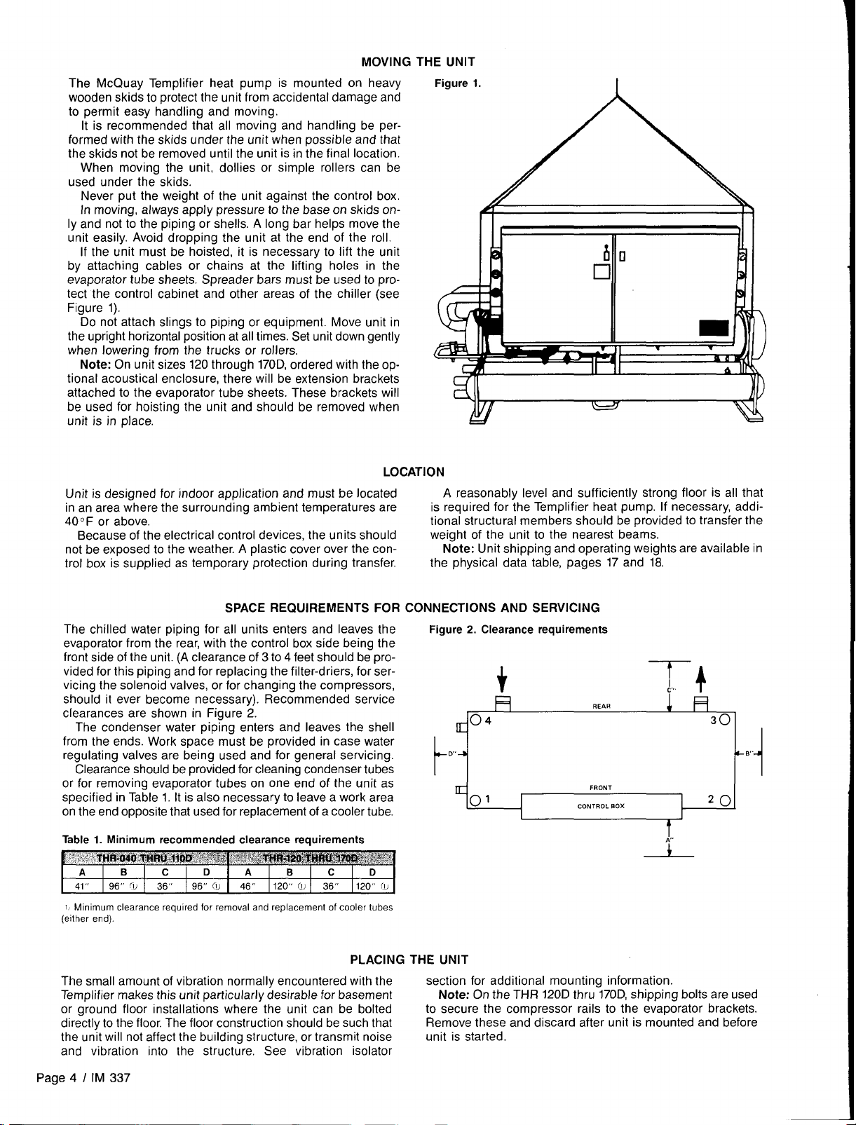
MOVING THE UNIT
The McQuay Templifier heat pump is mounted on heavy
wooden skids to protect the unit from accidental damage and
to permit easy handling and moving.
It is recommended that all moving and handling be performed with the skids under the unit when possible and that
the skids not be removed until the unit is in the final location.
When moving the unit, dollies or simple rollers can be
used under the skids.
Never put the weight of the unit against the control box.
In moving, always apply pressure to the base on skids only and not to the piping or shells, A long bar helps move the
unit easily. Avoid dropping the unit at the end of the roll.
If the unit must be hoisted, it is necessary to lift the unit
by attaching cables or chains at the lifting holes in the
evaporator tube sheets. Spreader bars must be used to protect the control cabinet and other areas of the chiller (see
Figure 1).
Do not attach slings to piping or equipment. Move unit in
the upright horizontal position at all times. Set unit down gently
when lowering from the trucks or rollers.
Note: On unit sizes 120 through 170D, ordered with the op-
tional acoustical enclosure, there will be extension brackets
attached to the evaporator tube sheets. These brackets will
be used for hoisting the unit and should be removed when
unit is in place.
Figure 1.
I
Unit is designed for indoor application and must be located
in an area where the surrounding ambient temperatures are
40F or above,
Because of the electrical control devices, the units should
not be exposed to the weather. A plastic cover over the control box is supplied as temporary ’protection during transfer.
SPACE REQUIREMENTS FOR CONNECTIONS AND SERVICING
The chilled water piping for all units enters and leaves the
evaporator from the rear, with the control box side being the
front side of the unit. (A clearance of 3 to 4 feet should be provided for this piping and for replacing the filter-driers, for servicing the solenoid valves, or for changing the compressors,
should it ever become necessary). Recommended service
clearances are shown in Figure 2.
The condenser water piping enters and leaves the shell
from the ends. Work space must be provided in case water
regulating valves are being used and for general servicing.
Clearance should be provided for cleaning condenser tubes
or for removing evaporator tubes on one end of the unit as
specified in Table 1. It is also necessary to leave a work area
on the end opposite that used for replacement of a cooler tube.
Table 1. Minimum recommended clearance requirements
B
A
961<
41“
I Minimum clearance required for removal and replacement of cooler tubes
(either end).
flJ 36,,
c
I 96” 0! 46 “
D
A B
120” @ 36 “ 120“ (u
LOCATION
A reasonably level and sufficiently strong floor is all that
is required for the Templifier heat pump. If necessary, additional structural members should be provided to transfer the
weight of the unit to the nearest beams.
Note: Unit shippinq and operating weights are available in
the physical data’ table, pages 17 and I8
Figure 2. Clearance requirements
01
FRONT
cONTROL BOX
20
1
f
The small amount of vibration normally encountered with the
Templifier makes this unit particularly desirable for basement
or ground floor installations where the unit can be bolted
directly to the floor. The floor construction should be such that
the unit will not affect the building structure, or transmit noise
and vibration into the structure, See vibration isolator
Page 4 I IM 337
PLACING
THE UNIT
section for additional mountina information.
Note: On the THR 120D thru 170D, shipping bolts are used
to secure the compressor rails to the evaporator brackets.
Remove these and discard after unit is mounted and before
unit is started.
Page 5
VIBRATION ISOLATORS
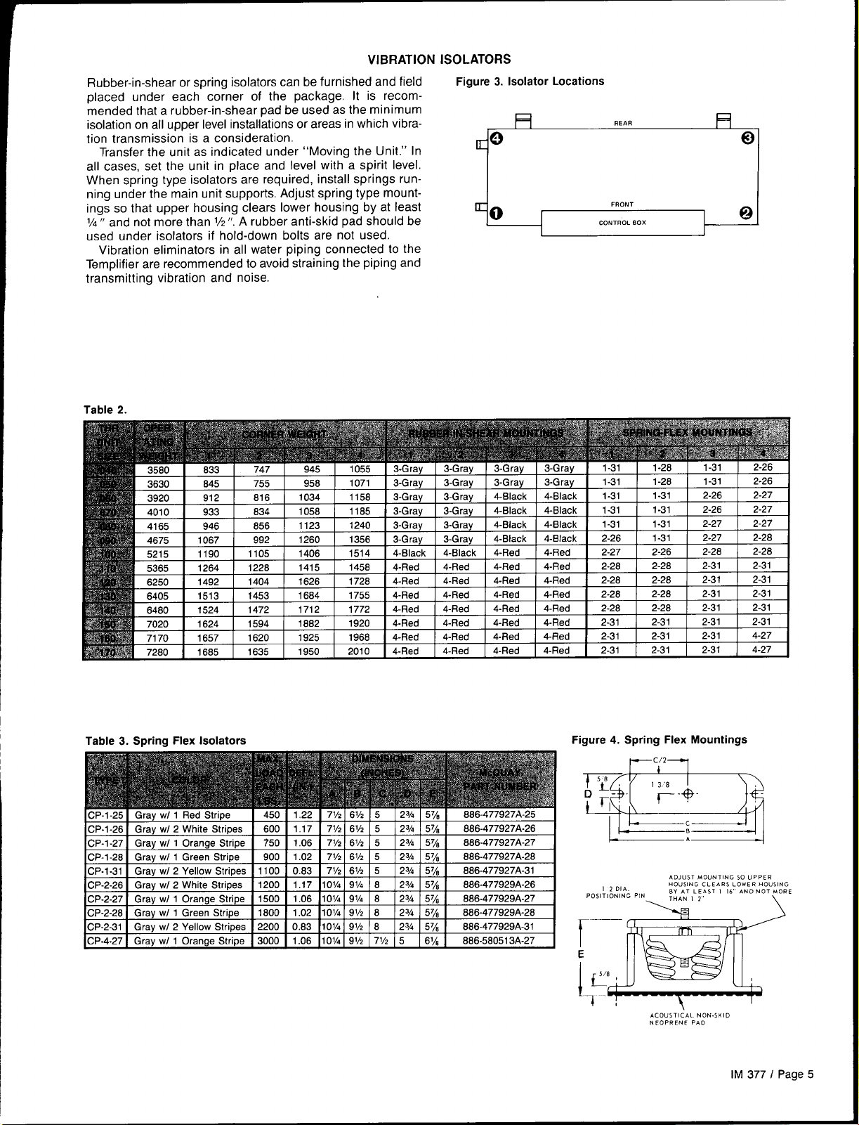
Rubber-in-shear or spring isolators can be furnished and field
placed under each corner of the package, It is recommended that a rubber-in-shear pad be used as the minimum
isolation on all upper level installations or areas in which vibra-
tion transmission is a consideration.
Transfer the unit as indicated under “Moving the Unit.” In
all cases, set the unit in place and level with a spirit level.
When spring type isolators are required, install springs running under the main unit supports. Adjust spring type mountings so that upper housing clears lower housing by at least
1/4” and not more than 1/2”.A rubber anti-skid pad should be
used under isolators if hold-down bolts are not used.
Vibration eliminators in all water piping connected to the
Templifier are recommended to avoid straining the piping and
transmitting vibration and noise.
Table 2.
-----
Figure 3. Isolator Locations
REAR
= o Q
K 0
FRONT
CONTROL BOX
!5
Q
Table 3. Spring Flex Isolators
CP-1-25 Gray WI 1 Red Stripe
CP-1-26 Gray WI 2 White Stripes
CP-1-27 Gray WI 1 Orange Stripe
CP-1-28 Gray WI 1 Green Stripe
CP-1-31 Gray WI 2 Yellow Stripes 1100 0.63 7%
CP-2-26 Gray WI 2 White Stripes
CP-2-27 Gray WI 1 Orange Stripe 1500 1.06 1
CP-2-28 Gray WI 1 Green Stripe
CP-2-31 I Gray w/ 2 Yellow Stripes I 2200 I 0.83 IIOV. I 9Vz I 6
CP-4-27 I Gray w/ 1 orange Stripe I 3000 I 1.06 II ol/4 [ 9’/2 I 7’/2 I 5 ] 6% ] 886-58051 3A-27
450 1.22 71/z
600 1.17 ?kJ
750 1.06 71/2
900 1.02 i’~/2
1200 1,17 I ol/4
1800 1.02 1ol/4
6V2 5
6VZ 5
6VZ 5
6VZ 5
6V2 5
9Vi 6
ov4
9v4 8
91/2 8
23h 5y8 886-477927A-25
23h 57/s 886-477927A-26
23h 5778 886-477927A-27
23,4 57/8 886-477927A-28
23h 578 886-477927A-31
23h 5y~
23h 5778 866-477929A-27
23h 5778 886-477929A-28
] 23A I 578 I 866-477929A-31
888-477929A-26
Figure 4. Spring Flex Mountings
wc/2y
ADJUST MOUNTING S0 UPPER
HOUSING CLEARS LOWER HOUSING
BY AT LEAST I 16’ AND NOT MORE
THAN I 2
\
w
\
ACOUSTICAL NON. SKID
NEOPRENE PAD
1
I 2 DIA
POSITIONING PIN
r–
E
ivJ_
1
4!
\
I
IM 377 I Page 5
Page 6
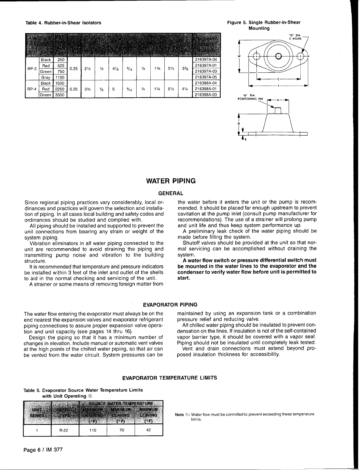
Table 4. Rubber-in-Shear Isolators
Figure 5. Single Rubber-in-Shear
Mounting
-D DIA
,-0- DIA.
‘Os’’’O”’”’ w--A--
a
WATER PIPING
Since regional piping practices vary considerably, local ordinances and practices will govern the selection and installation of piping. In all cases local building and safety codes and
ordinances should be studied and complied with.
All piping should be installed and supported to prevent the
unit connections from bearing any strain or weight of the
system piping.
Vibration eliminators in all water piping connected to the
unit are recommended to avoid straining the piping and
transmitting pump noise and vibration to the building
structure.
It is recommended that temperature and pressure indicators
be installed within 3 feet of the inlet and outlet of the shells
to aid in the normal checking and servicing of the unit.
A strainer or some means of removing foreign matter from
EVAPORATOR PIPING
The water flow entering the evaporator must always be on the
end nearest the expansion valves and evaporator refrigerant
piping connections to assure proper expansion valve opera-
tion and unit capacity (see pages 14 thru 16).
Design the piping so that it has a minimum number of
changes in elevation. Include manual or automatic vent valves
at the high points of the chilled water piping, so that air can
be vented from the water circuit, System pressures can be
GENERAL
the water before it enters the unit or the pump is recom-
mended. It should be placed far enough upstream to prevent
cavitation at the pump inlet (consult pump manufacturer for
recommendations). The use of a strainer will prolong pump
and unit life and thus keep system performance up.
A preliminary leak check of the water piping should be
made before filling the system.
Shutoff valves should be provided at the unit so that normal servicing can be accomplished without draining the
system.
A water flow switch or pressure differential switch must
be mounted in the water lines to the evaporator and the
condenser to verify water flow before unit is permitted to
start.
maintained by using an expansion tank or a combination
pressure relief and reducing valve.
All chilled water piping should be insulated to prevent con-
densation on the lines. If insulation is not of the self-contained
vapor barrier type, it should be covered with a vapor seal.
Piping should not be insulated until completely leak tested.
Vent and drain connections must extend beyond pro-
posed insulation thickness
for accessibility.
Page 6 I IM 377
EVAPORATOR TEMPERATURE LIMITS
Page 7
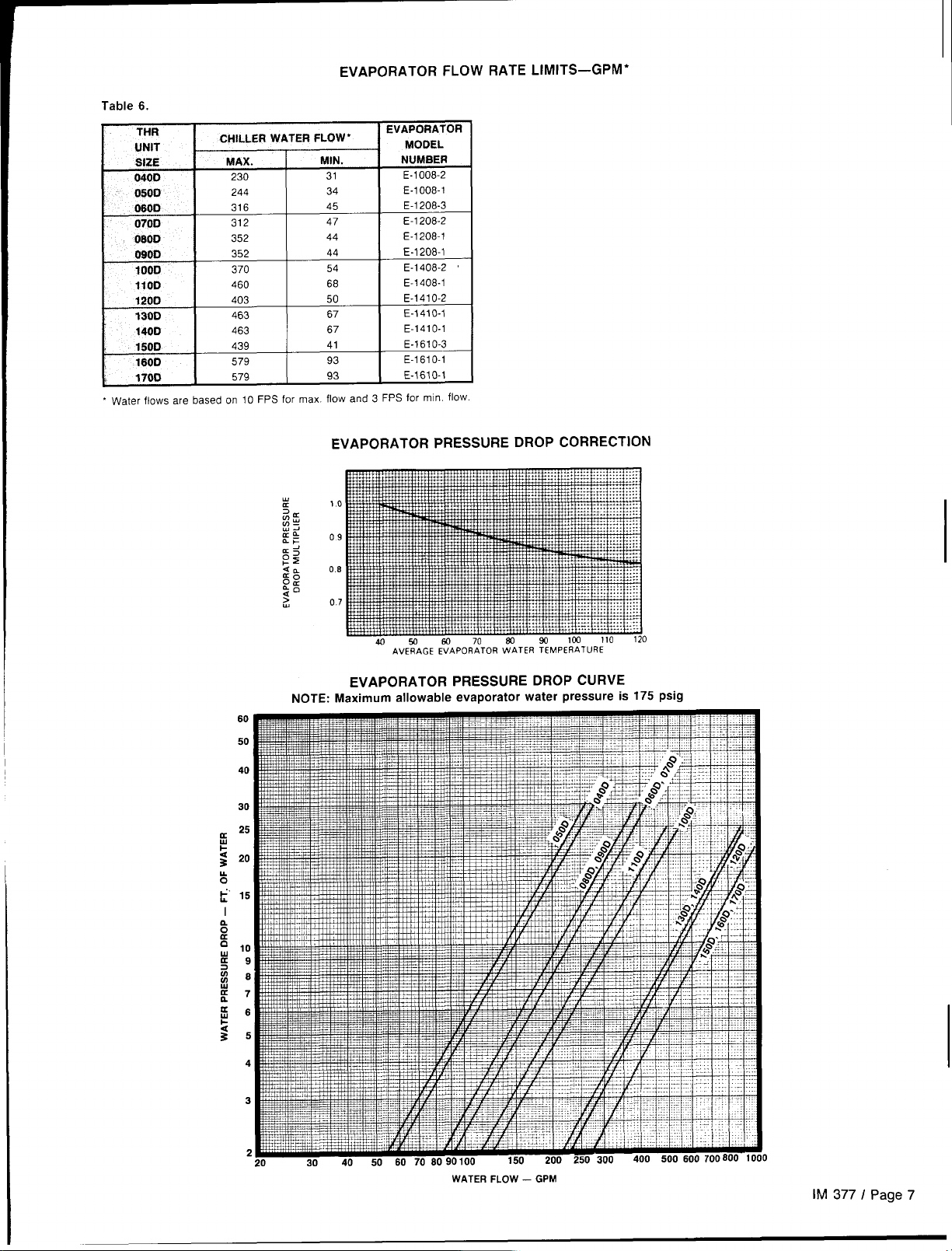
EVAPORATOR FLOW RATE LIMITS–GPM*
Table 6.
THR
UNIT
SIZE
040D
0500
0600
0700
080D
0900
1000
1100
1200
t30D
1400
1500
1600
1700
‘ Water flows are basedon 10 FPS for max. flow and3 FPS formin, flow.
CHILLER WATER FLOW *
MAX.
230
244
316
312
352
352
370
460
403
463
463
439
579
579
MIN.
31
34
45
47
44
44
54
68
50
67
67
41
93
93
EVAPORATOR
MODEL
NUMBER
E-1008-2
E-1OO8-1
E-1208-3
E-1208-2
E-1208-1
E-1208-1
E-1408-2
E-1408-1
E-141 O-2
E-141 O-1
E-141 O-1
E-161 O-3
E-161 O-1
E-161 O-1
EVAPORATOR PRESSURE DROP CORRECTION
EVAPORATOR PRESSURE DROP CURVE
NOTE: Maximum allowable evaporator water pressure is 175 psig
WATER FLOW –GPM
lM3771Page7
Page 8
CONDENSER WATER PIPING
THR condensers have factory manifolds for single inlet and
outlet connections. Water flow may be 2-pass parallel, 4-pass
parallel or 8-pass series/parallel to suit the application, Refer
to Figure 6 to determine condenser water circuiting arrangement. For proper performance, the condenser water must
enter the bottom connection of the condenser on all circuiting
arrangements.
Condenser water pressure drop for the unit should be
measured at the common inlet and outlet pipe, through a port
provided by the installing contractor. All pressure drop measurements should be made with the same gauge to insure
an accurate reading, Before the pressure drop curves can be
read, the pressure drop values on the curve must be corrected
based on the average hot condenser water temperature. The
correction factor can be obtained from page 9, and then
multiplied by the values on the pressure drop curves to adjust them according to the average water temperature in the
system.
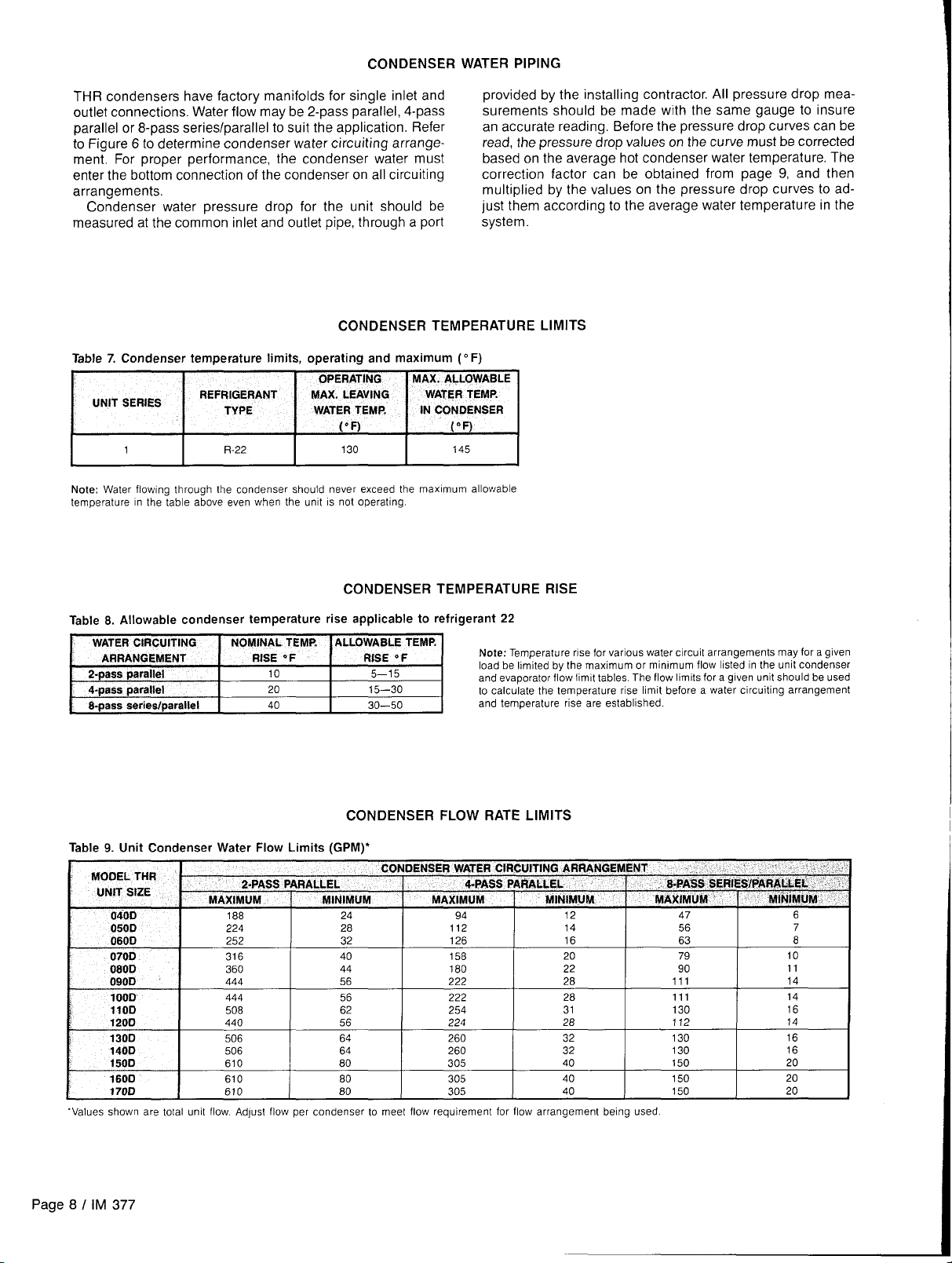
CONDENSER TEMPERATURE LIMITS
Table 7. Condenser temperature limits, operating and maximum ( 0F)
!,
UNIT SERIES
REFRIGERANT
TW%
OPERATING MAX. ALLOWABLE
MAX. LEAVING
WATERTEMP.
WATERTEMP, IN CONDENSER
(“F) (“F)
I
Note: Water flowlng through the condenser should never exceed the maximum allowable
temperature in the table above even when the urmt IS not operating.
1
R-22
I
I
130
I
145
I
CONDENSER TEMPERATURE RISE
Table 8. Allowable condenser temperature rise applicable to refrige
!rant 22
Note: Temperature rise for various water circuit arrangements may for a given
load be limited by the maximum or minimum flow hsted in the unit condenser
and evaporator flow Iimlt tables. The flow Iimlts for a given unit should be used
to calculate the temperature rise limit before a water circuiting arrangement
and temperature rise are established.
CONDENSER FLOW RATE LIMITS
Table 9. Unit Condenser Water Flow Limits (GPM)*
060D
070D
080D
090D
100D
I1OD 508
1200 440 56
130D 506 64 260 32
\
140D 506 64 260 32
150D 610 80
1600 610
170D 610
‘Values shown are total unit flow AdJust flow per condenser to meet flow requirement for flow arrangement being used
252 32 126 16 63 8
316
360
444 56
444
40
44
56
62
80
80
158
180 22 90
222
222
254
224
305
305
305
20 79 10
28 111 14
28 111 14
31 130
28 112 14
40 150
40 150 20
40 150
130 16
130 16
11
16
20
20
Page 8 I IM 377
Page 9
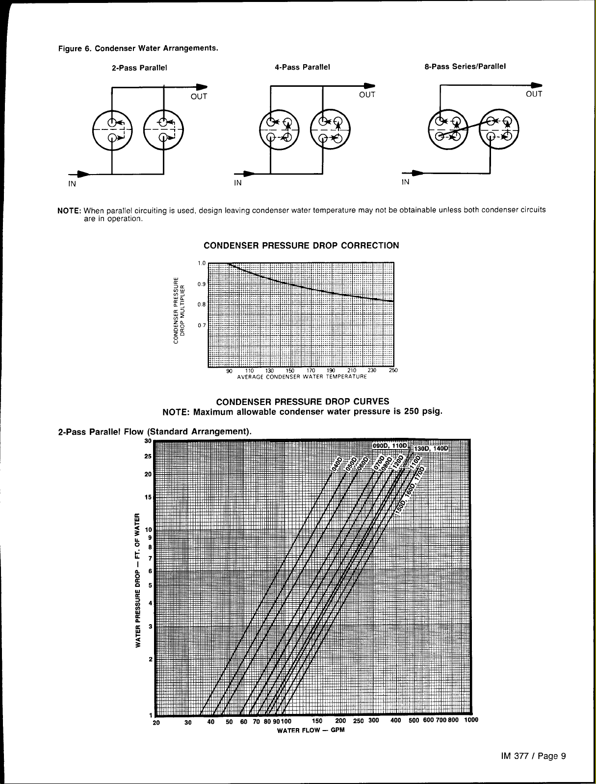
Figure 6. Condenser Water Arrangements.
2-Pass Parallel
m
OUT
IN
NOTE: When parallel circuiting is used, design leaving condenser water temperature may not be obtainable unless both condenser circuits
are in operation.
IN
4-Pass Parallel
w
OUT
8-Pass Series/Parallel
-
OUT
IN
CONDENSER PRESSURE DROP CORRECTION
10
#
09
2E
W;
:: O*
J
~$
m
z% o,
gg
0
u
w
CONDENSER PRESSURE DROP CURVES
NOTE: Maximum allowable condenser water pressure is 250 psig.
2-Pass Parallel Flow (Standard Arrangement).
k
t
n
o
K
n
u
a
:
m
u
K
n.
a
w
1-
S
110 130 lwl
AVERAGECONDENSERWATERTEMPERATURE
170 193 210
230 253
WATER FLOW – GPM
IM 3771 Page 9
Page 10
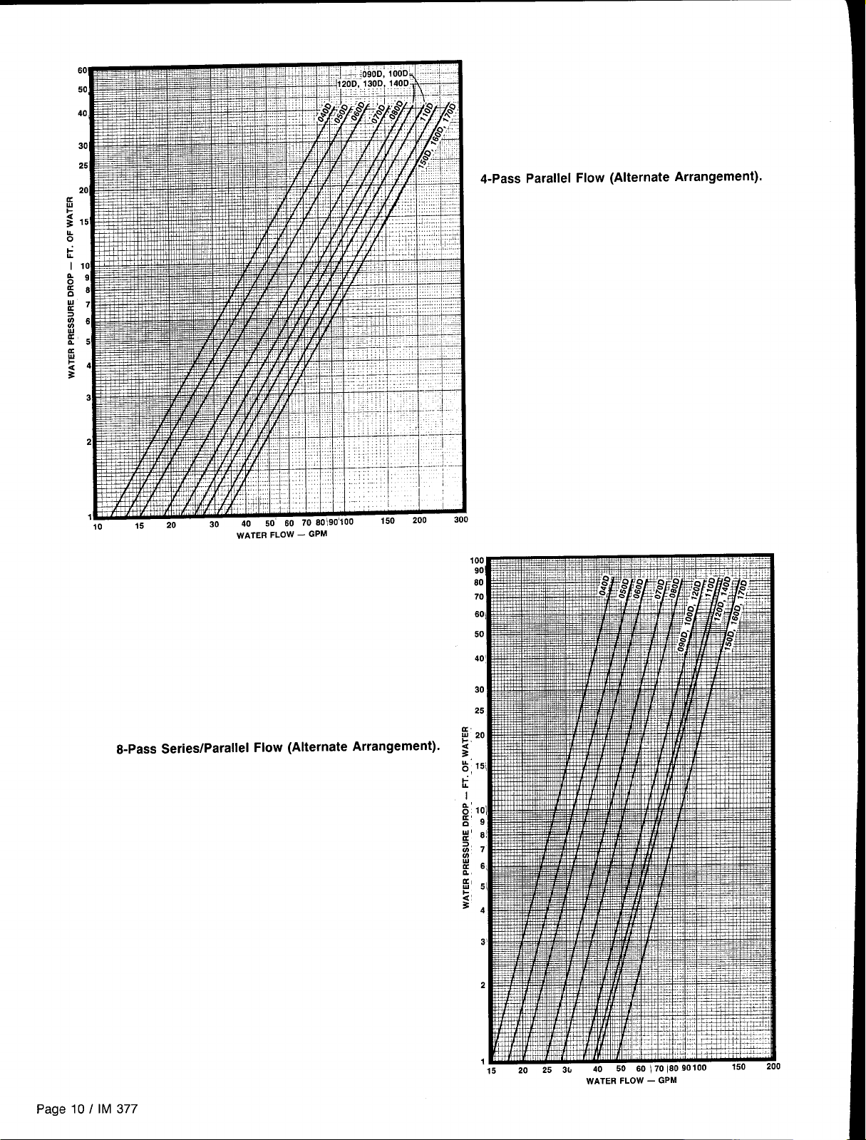
4-Pass Parallel Flow (Alternate Arrangement).
.
8-Pass Series/Parallel Flow (Alternate Arrangement).
WATERFLOW– GPM
Page 10 / IM 377
WATERFLOW— GPM
Page 11
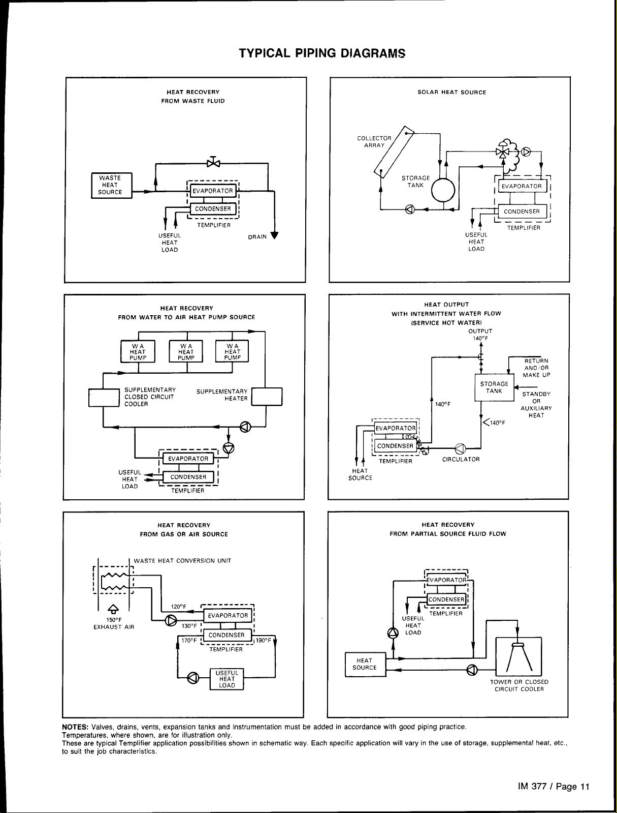
TYPICAL PIPING DIAGRAMS
HEAT RECOVERY
FROM WASTE FLUlO
I
WASTE
HEAT
SOURCE
up ORAIN1
HEAT
LOAD
FROM WATER TO AIR HEAT PUMP SOURCE
SUPPLEMENTARY
CLOSEOCIRCUIT
COOLER
HEAT RECOVERY
P
1=
--------
I
USEFUL
HEAT
LOAO
J
------ -.
TEMPLIFIER
L
-
SUPPLEMENTARY
HEATER
SOLAR HEAT SOURCE
COLLECTOR
ARRAY
I
TANK
i i
I_/
USEFUI
HEAT
LOAD
WITH INTERMITTENT WATER FLOW
HEAT OUTPUT
(SERVICEHOT WATERI
OUTPUT
140° F
TEMPLIFIER
t
STORAGE
TANK
<140”C
t- STANOBY
I
OR
AUXILIARY
I I
A
140°F
P
I
I 1(T
I
L--------J
f
b
HEAT
SOURCE
TEMPLIFIER
CIRCULATOR
L
,r HEAT
HEAT RECOVERY
FROM GAS OR AIR SOURCE
------ _
r
I
i
1
- ----.- .I
EXHAUSTAIR
NOTES: Valves, drains, vents, expansion tanks and instrumentation must be added in accordance with good piping practice.
Temperatures, where shown, are for illustration only.
These are typical Templifier application possibilities shown in schematic way. Each specific application will vary in the use of storage, supplemental heat, etc.,
to suit the job characteristics
WASTE HEATCONVERSIONUNIT
#
I
4
150°F
170”F *
L------ ----
-------. ~
TEMPLIFIER
FROM PARTIAL SOURCE FLUIO FLOW
HEAT RECOVERY
-------
!~~
—EVAPORATOR-
I
I
CONDENSER!
L
--..-.-
1+=
TEMPLIFIER
USEFUL
1
TOWEROR CLOSEO
CIRCUITCOOLER
IM 377 I Page 11
Page 12
WATER QUALITY
The water flowing through the condenser and evaporator must
be of suitable quality for use with standard materials of
construction:
Condenser: Steel heads and tube sheets,
rubber gaskets, copper tubes.
Evaporator: Steel shell, copper tubes,
polypropylene baffles
Any additives that may be harmful should not be used.
quality may deteriorate later, an intermediate heat exchanger
is recommended, Plate type exchangers should be considered
for minimum temperature approach at economical cost.
Note: If cooling”tower or other source water containing dirt,
sediment or other foreign matter is used, assure that take-offs
to the Templifier are at the top of horizontal pipelines to minimize foreign matter getting into the evaporator. Depending
on water conditions, dual strainers and/or a settling drum
should be considered.
Where water or other fluids of unsuitable quality, or where
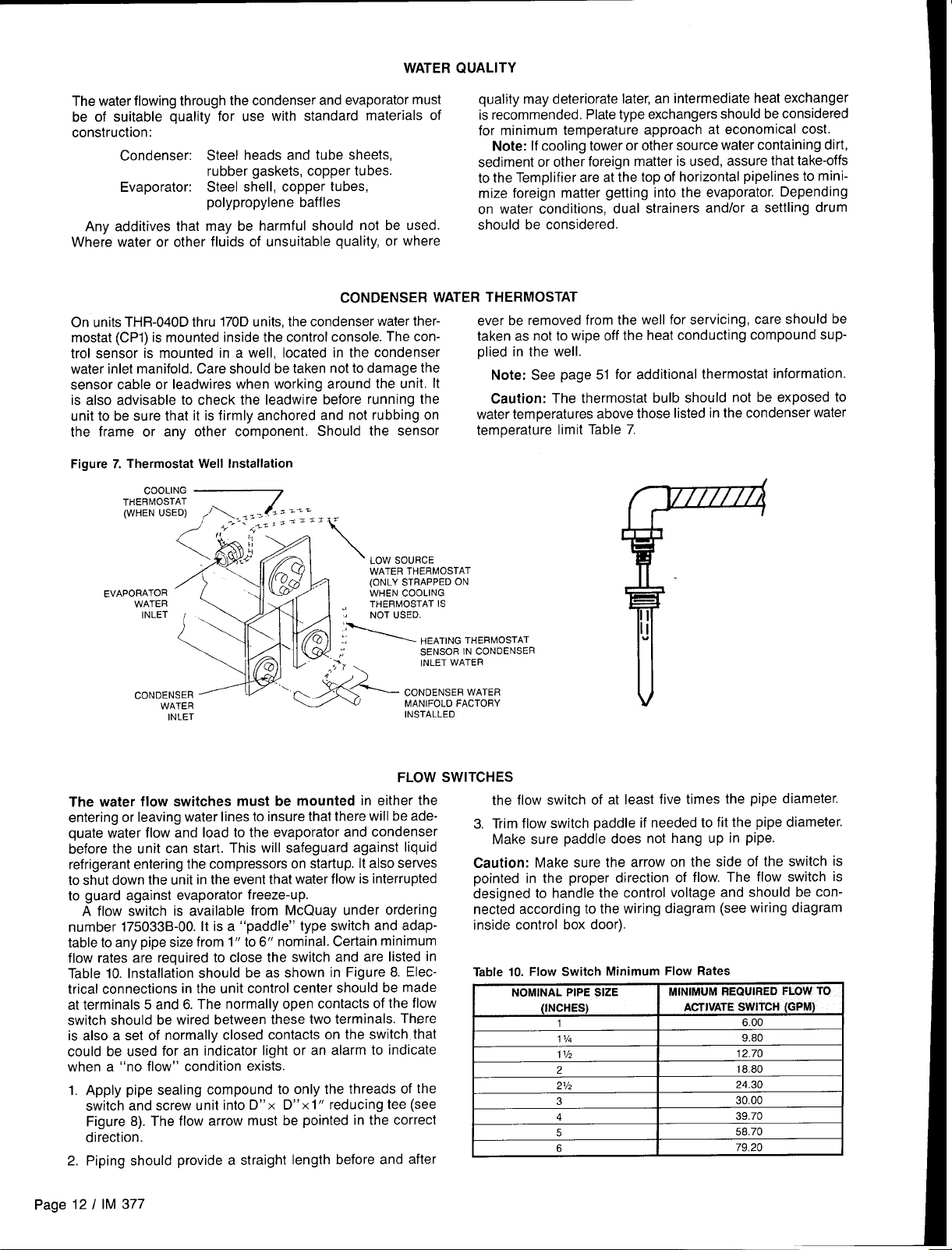
CONDENSER WATER THERMOSTAT
On units THR-040D thru 170D units, the condenser water thermostat (CP1) is mounted inside the control console. The con-
ever be removed from the well for servicing, care should be
taken as not to wipe off the heat conducting compound suptrol sensor is mounted in a well, located in the condenser plied in the well.
water inlet manifold. Care should be taken not to damage the
sensor cable or leadwires when working around the unit. It
is also advisable to check the leadwire before running the
unit to be sure that it is firmly anchored and not rubbing on
the frame or any other component, Should the sensor
Figure 7. Thermostat Well Installation
Note: See page 51 for additional thermostat information.
Caution: The thermostat bulb should not be exposed to
water temperatures above those listed in the condenser water
temperature limit Table 7.
EVA
INLET
The water flow switches must be mounted in either the
entering or leaving water lines to insure that there will
INSTALLED
FLOW SWITCHES
be adequate water flow and load to the evaporator and condenser
before the unit can start. This will safeguard against liquid
refrigerant entering the compressors on startup. It also serves
to shut down the unit in the event that water flow is interrupted
to guard against evaporator freeze-up.
A flow switch is available from McQuay under ordering
number 175033 B-00. It is a “paddle” type switch and adaptable to any pipe size from 1“ to 6“ nominal. Certain minimum
flow rates are required to close the switch and are listed in
Table 10. Installation should be as shown in Figure 8. Electrical connections in the unit control center should be made
at terminals 5 and 6. The normally open contacts of the flow
switch should be wired between these two terminals. There
is also a set of normally closed contacts on the switch that
could be used for an indicator light or an alarm to indicate
when a “no flow” condition exists.
1. Apply pipe sealing compound to only the threads of the
switch and screw unit into D“x D“x1” reducing tee (see
Figure 8). The flow arrow must be pointed in the correct
direction.
2. Piping should provide a straight length before and after
R
the flow switch of at least five times the pipe diameter.
3. Trim flow switch paddle if needed to fit the pipe diameter.
Make sure paddle does not hang up in pipe.
Caution: Make sure the arrow on the side of the switch is
pointed in the proper direction of flow.
The flow switch is
designed to handle the control voltage and should be connected according to the wiring diagram (see wiring diagram
inside control box door).
Table 10. Flow Switch Minimum Flow Rates
NOMINAL PIPE SIZE MINIMUM REQUIRED FLOW TO
(INCHES) ACTIVATESWITCH (GPM)
1 6.00
11A
I 1/2
2 18.80
21/2
3
A
5
6
I
9.80
12.70
24.30
30.00
39.7C
-. .
58.70
79,20
Page 12 I IM 377
Page 13
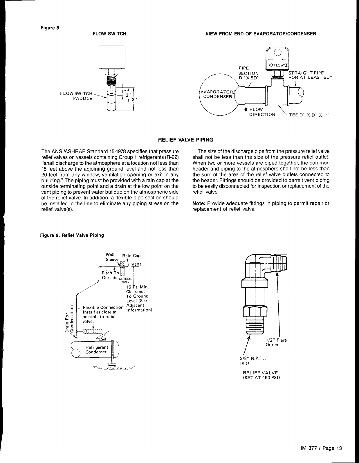
Figure 8.
FLOW SWITCH
PADDLE
FLOW SWITCH
*
1“2,,
VIEW FROM END OF EVAPORATOR/CONDENSER
--
m
PIPE
-EF;?’ )
~ FLOW3
w
STRAIGHT PIPE
FOR AT LEAST 5D”
Y
The ANSI/ASHRAE Standard 15-1978 specifies that pressure
relief valves on vessels containing Group 1 refrigerants (R-22)
“shall discharge to the atmosphere at a location not less than
15 feet above the adjoining ground level and not less than
20 feet from any window, ventilation opening or exit in any
building.” The piping must be provided with a rain cap at the
outside terminating point and a drain at the low point on the
vent piping to prevent water buildup on the atmospheric side
of the relief valve. In addition, a flexible pipe section should
be installed in the line to eliminate any piping stress on the
relief valve(s).
Figure 9. Relief Valve Piping
rl
f“’”
I
‘EI %%’:,w%’on
I ;~;~ble to relief
~:
c:
‘;
c
66
3“
Wall
Rain Cap
“eeve&Vent
Pitch !O
Outside OUTSIDE
[r
WALL
15 Ft. Min.
Clearance
To Ground
Level (See
Adjacent
Information)
RELIEF VALVE PIPING
The size of the discharge pipe from the pressure relief valve
shall not be less than the size of the pressure relief outlet.
When two or more vessels are piped together, the common
header and piping to the atmosphere shall not be less than
the sum of the area of the relief valve outlets connected to
the header. Fittings should be provided to permit vent piping
to be easily disconnected for inspection or replacement of the
relief valve.
Note: Provide adequate fittings in piping to permit repair or
replacement of relief valve.
Refrigerant
Condenser
[1
/
3/8” N.P.T
Inlet
RELIEF VALVE
(SET AT 450 PSI)
Outlet
IM 377 / Page 13
Page 14

Figure 10. THR-040D thru 11 OD, 2-pass parallel.
‘i- I ‘-w:’”’
29 ~
DIMENSIONAL DATA
— L—
I %4 MOUI{TIIIG HOLES -1 k7vz
7,,8 DIA
b IEVLP03LTOR
w,i TER !PILET)
~ fl:~CTATOR
f
. . .
—90 7/8
– POWER
I 1
k“
A [EVAPORATOR
4
--F
wIRING
CONNECTION
I?; OUIRED
FOR TUBE
REMO$IAL
EITHER
END
!
u
I
I
WATER OUTLET)
de
h
Table 11. THR-040D thru 11 OD, 2-pass parallel.
THR
MODEL
N&
O@
0500
060D
070D
0s00
OSOD
100D
11OD
Ficrure 11. THR-120D thru 170D, 2-pass parallel.
Recommended
t-36”–
lFOr ‘“W’””’
“D” Evaporator _
Water Corm
MAX. OVERALL
DIMENSIONS
L
125% 34
125%
125?4 34
125% 34
125% 34
127
127
127
— 34” ~46°
\
w
34
34 65?4
34
34
EVAP. WATER CONN.
A
H
621/4 23h
621/4
633~
633A
633A
661/4
661/4
IClearance” ‘
—
23A
31/2
31/2
31/2
31/2
51/2
51/2
H
(VIcTAULtC)
c
23%
23~8
24V8
24T/o
24VB
261/2
271~
271~
1] Door SwIna
e
r
‘f
P“ Victaul,c
Top Outlet
Bottom Inlet
---E
CONDENSER WATER
CONNECTIONS (VICTAULlc) ~
D
4
4
E “F
65/8
65A
65/8
5
65/8
5
6%
5
71/2
5
71/2
6
71/2
6
Q&31fl,.--j
\
11~*
11~8
lly~
llye
lly*
131A
131/s
13%
x-Ae
J
Q
11~/2
17%
111/2
171h
I I 1/2
171~
111/2
171/E
I I 1/2
171/E
161/4
12y8
161/4
12y8
161/4
123/8
~ Ind(cator L,ghts
/
. . . . . . . . .
~ u:
P
283/3 561/k
3
28% 58%
3
28% 59% 43
3
26~8 59% 43
3
28% 59% 43
3
293A 61 1/>
4
29% 62%
4
29% 62%
4
1517A ~’’””l
D
Power Wlrlng
ConnectIons
CENTER, OFWWWTY
‘
“x
4278 23
42~8 23
431/2
4378 28
433~
y ‘ “z
251/3
251A
25%
27V8 13
28
i
\
13
13
123A
123~
123A
I 25h
125/8
Requ,red For
ube Removal
E,ther End
I
I
t
L..
27A -
Tabie 12. THR-120D thru 170D, 2-pass parallel.
34 77
34
34
34 77
77
77
160D
160D
170D
Page 14 I IM 377
1517*
1517~
151y~
151T/~
EVAP. WATER CONN.
3131A
51/2
51/2
51/2
51/2
3131/4
3131/4
301/4
6
6
6
6
Evaporator
‘AL
Water Inlet
1
I
CONDENSER WATER
131/Is
77A 6
131/16
7~16
13~h6
7~16
131/Is
7YIS
109A6
109/16
10%6
10%6
@
167/,s 4
167/,6 4
167/,6 4
167/,,3 4
~ A fi::~:;e,
163/4
l-/-
CENTER OF
@liWITY .’
,
P x y z
293~
293A
293~
293A
561/3
56%
561/2
561/4
32V8
32%
331/4
337/2
131/2
131/2
13ye
13y8
Page 15
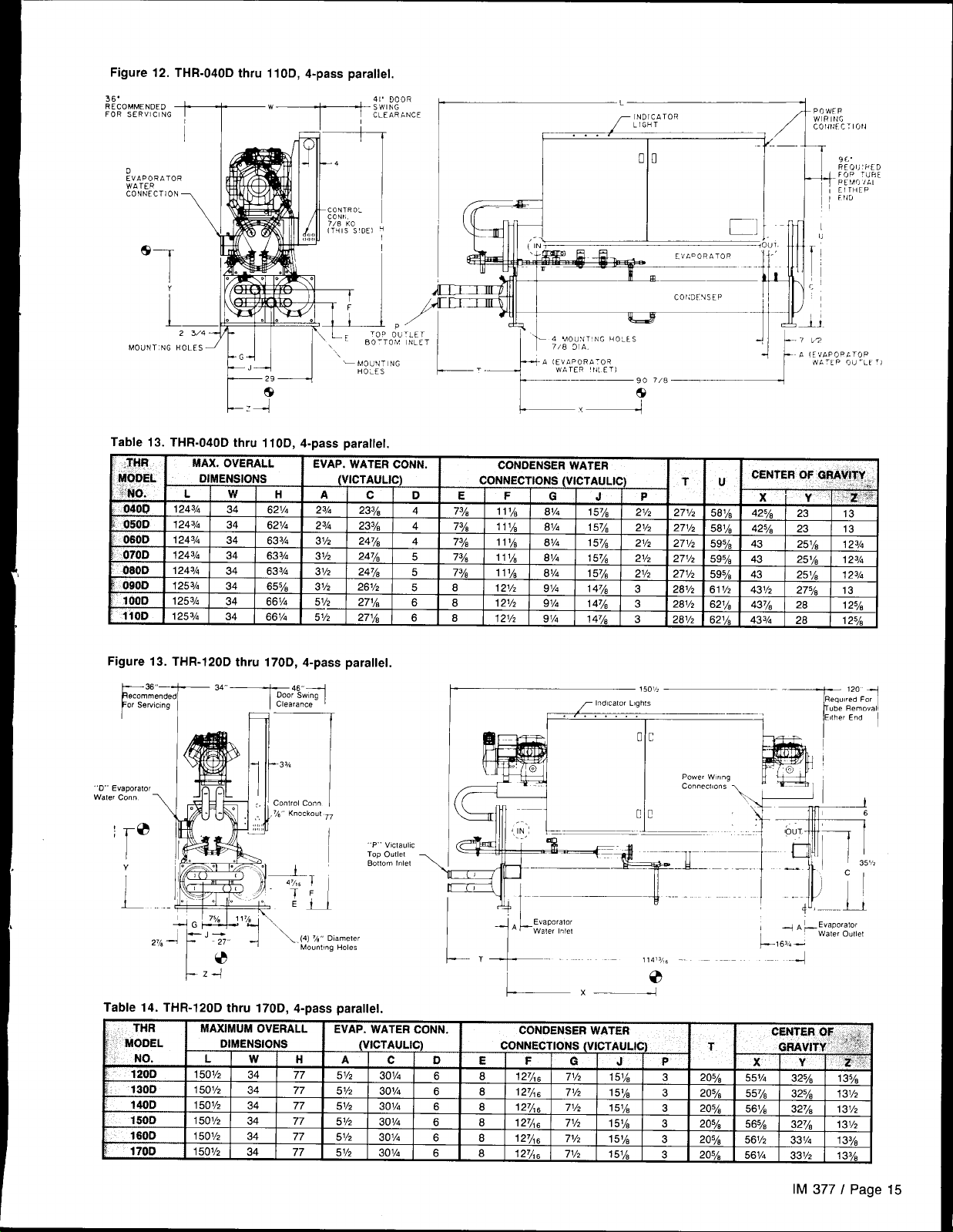
Figure 12. THR-040D thru 110D, 4-paas parallel.
36RECOMMENDED
FOR SERVICING
D
EVAPORATOR
WATER
CONNECTION
1
\
SI 1111/ II (iTls”s’DE1
I
&3’1
L–
1.
-1
2 3/4 -
MAX. OVERALL
DIMENSIONS
L
124% I 34
124% I 34
124% ] 34
124%4
124% 34
125% 34
125% 34
125% 34
MO UN T:NG HOLES
Table 13. THR-040D thru 110D, 4-pass parallel.
,THR
k
. . .
T- l\L
29+
r
?49
w
34
H
621A
621/4
I
633A 31/2
&j3~
633A
65%
661/4
661/4 51/2
F
II
E
BOTTOM
‘.
...-
EVAP. WATER CONN.
(WCTAULIC)
A
23A
23~
31/2
31/2
31/2
51/2
c D
23Y8 4
23%
24~B
24~a
24Y8
261/2
271~
271~
TO. Ou
P
‘LET
INLET
4 7%
4
5 72/~
5
5 8
6
6 8
I
irD=r
1
E F
73/4
I
73/3
778 11~~
8
. . .
nn
=lnrz
IIL‘i%
r
CONDENSER WATER
CONNECTIONS (VICTAULIC)
111/s
111A
111/s
111A
I 21/2 gl~
121/2
121/2 914
ka
— 4 UOUNT’NG HOLLS J~
7/8 31A
1-1
r---
—Y<e
G
81/4
61A
61/4
al~
81/4
91/4
/
—90 7/8
J
1578
157/,
157/8
157/8
157/8
1478 3
14y8 3
14T/~ 3
I
EVLDORb TOP 4-’
CO I:DF!SEP
I I
P
21/2
271/2
21/2
271/2
21/2
271/2
21/2 271/2
21/2
271/,
281/2
281/2
281/2
-/
T-l n r
LJ[. ”-
<oUT.
,1
--ill
--/
t-
CENTER OF
y
2514
251k
251~
27Ye 13
26
581~
42S~ 23
581~
425~ 23
59y* 43
595A 43
59y* 43
61 1/2 431/2
621A
437/, 28
433A
621A
x
-P OWFI?
WIRING
c01it4Fc Tlotl
1)
c’
b7
GRAV!W.
!3
,..’;J;:F
13
13
lz3~
123A
123~
123/8
125h
1
,’::
Figure 13. THR-120Dthru 170 D,4-passparalleI.
— 46,,
Door SW,ng
i
Clearance
D,, Evaporamr
walercm”
:@
T
Y
I
,
Control Con.
% Knockout ,7
I
I
I
L
lanleter
Holes
l-z+
Table 14. THR-120D thru 170D, 4-pass parallel,
THR
>
MODEL
NO.
1201J 15u12
1300
!
140D
D
wor
160D
170D
MAXIMUM OVERALL
I
DIMENSIONS
L w H A c o
# .. -.,.
150Yz I
!
1501/2]~
1
1501/z I 34
I
i501/z I
I
1501/2 34
34
!
I
34
I
34
34
EVAP. WATER CONN.
1
I
51/2
77
I
51/2 3131,4
77
51/2
77
51/2
77
51/2 301~
77
I
5 1/,
77
----- ,.w
P Vlcla”l,c
ToDOu!lel Bottom Inlet
(VICTAULIC)
30 1/4
I
3r31A
3(31/4
q(l
1/”
I
150%
Ind,cator L,ghls
. . . . . .
I
\
I +1 4“-—.-~
I- T+... __
1
‘AL
Evaporator
Wz!er Inlet
11413/,, –-
0
CONDENSER WATER
CONNECTIONS (WCTAULIC
F F n .1
1 I !
127A6
8
I
8 12fi6
127A6
8
8 127/4~
8 127/, ~
8I127/,6
71/2
151/& I
71/2
151/s
71/2
151~
71/2
151A
77/2
151/s
71/2
151/s
I
I
I I
$ 1
I I
h!:.m
3
203/,
3
205A
3 203/~
3
203/8
!
3
2os~
1
557/*
561A 32VB
56~B
561/2
I
561/4 331/2
1
I
I R
1
I
m
6
I
6
6
6
6
!
I
–~ 120 -
Req., red For
“be Remov:
.p.aporatm
~
--4
325h
32V8
331~
Erlher End
waler
I
1
131/2
131/2
133h
133/4
I I
(
k16,4-–
CENTER OF ..+ “]
35,%
outlet
31/2
I
I
I
IM 377 I Page 15
Page 16
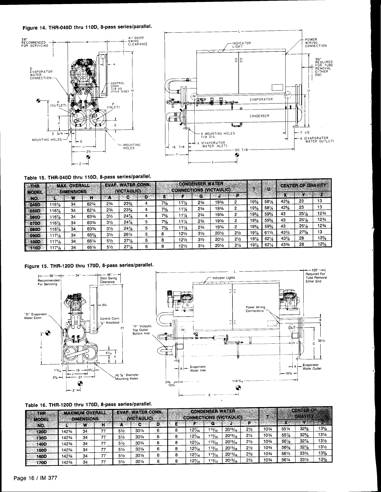
Figure 14. THR-040Dthru 11OD, 8-pass series/parallel.
L7/yiiR$’:LEs,o,/
‘“”NT’NGH”LESJ++] ‘-,,,,:
Lz4e
Table 15. THR-040Dthru 11OD, 8-pass series/parallel.
.-rrn
7 !/2
4
A (EVAPORATOR
J~
—T
e
WATER OUTLETI
Fiaure15. THR-120Dthru 170 D,8-pass series/parallel.
_
l==
1
Q~,-
Door Sw,ng
Clearance
- 3%
~
Control Con.
~%,,Knockout
/
1
p,, V,claullc
77
Too Outlet
BotlomInlet
*36+ _. 3--
Recommended
For Sermng
,,D ~
Waler
I
Lz -/
L
T Ind!calor L,ahts
I V’”””””:, I
3 D
Power W,r(ng
Connections ~
Evaporator
‘AL
Waler Inlet
‘1
~o,A+ --
L——- x –– ---J
114>%-
0
L6:~fi~r~fi”
120--+
Mequired For
Tube Flemoval
E(lher End
Page 16 / IM 377
Page 17

PHYSICAL DATA
Table 17. THR-040D thru 11 OD
~ UNIT SIZE
Nominal Horsepower
Number
Speed RPM (60 Hz/50
No. of Cylindera
Oil Charge (Oz.)
Discharge Line Size (In.)
Number 2 2 2
Diameter (In,)
Tube Length (In.) 96 I 96
Design W.P, (PSIG):
Refrigerant Side
Water Side
I Rc,l,.nfl=, ore
Purge Valve Flare
Liquid Subcooler
No. Water Passes
Pump-Out Capacity 0
I
Connections:
Water inlet&Outlet (Victaulic)l 2V2
P
No. Water Passes
Pump-Out Capacity @
I
Connections:
Water Inlet & Outlet (Victaulic)
Water Passes@
No.
Pump-Out Capacity 0 130
Hz) _
I
20 ] 25
1],
040D
0500
25 I 25 30 35 35 35
1 1
1750/1 450 1750/1 450 1750/ 1450
4
I 4
136 136 136 I 1:
I
11A 11/2
8Y8 85/8 8%
4 4 4 6 6
36
11A 1ye 1yo
11A
85/8 878
96 I 96 96 [ 96 96 I 96
450 450
I
I
250
1/,
Y4 & ~/2
I
I
250
1/..
1/4 & J/2
Integral Integral Integral Integral Integral
2 I 2 I 2 12 I 2 / 2 I 2 I 2 I 2 I 2 I 2 I 2 I 2 12 I 2 I .2
I
130 130
I
I
41414 41414/4 4 14 I 4 14 14 I 4 I 4 14 I 4
I
130
I
2V2
4 4
130
130 125
21/2 21/2 21/2 21/2 21/2
130 130
21/2 27/2
130
21/2
4 4 14 14 14 I 4 I 4 14 I 4 I 4 14 I 4
130 130
130
060D
070D
080D
G60D
I
1OOD
I
cOMPRESSORS
40 40 50 50 50
1 1 1
152 160
1750/ 1450
160 160
1% 1ye
1 1 1 1
1
1750 II 450
6 6 6 8 8 8
242
1ye
1750/ 1450 1750/
242
260
260 260
1% 1yeI1ye 1ye 1yeI1ye
1
CONDENSERS
2 2
85~ 6Y8 85/, 85/3 85A
96 ] 96 96 ] 96 96 I 96
450 450 450 450 450 450
250 250 250
1/,
I
I
J14 & V2
I v?
~/4 & ~/2
I
I v, I v? I
Y4 & J/2
I
2.PASS ARRANGEMENT
125 116 116
21/2 21/2
109 199 199
109
21/21 3 I 3 I 3 I 3
21/2
4-PASSARRANGEMENT
125 125 116 116 109
21/2 21/2 21/2
21/2
109 199
21/2 21/2 I 3 I 3
2 2 2
103A 103/4
103A
250
I
250 I 250
I
Y4 & ~/2
Integral
!
7/4 & 3/2
Integral
188
199 166
313/3 3
8-PASSARRANGEMENT
125 125 116 116 109 109
199 199 166 188 166 188
1100
I
60 60 I 60
1 1 1
1750/1 450
1450
8 618
260 260
lf33~
v, I v? I
166 168
186
103A 103~
96 ! 96
J/a & 7/2
1
Integral
3 3
188 188
4
260
15h
I
186
4
I
Water inlet&Outlet (Victaulic) I 2 21212121212 121212
EVAPORATOR
Refrigerant Circuits
No.
Diameter (In.)
Tube Length (In.)
Water Volume (Gallons)
Refrigerant Side D.W.P. (PSIG)
Water Side D.W.P. (PSIG)
Water Connections:
Inlet & Outlet (NPT EXT.)
Drain & Vent (NPT INT.)
2 2 2
103,4
lo3~
lz3~
96 96 96
20.6 17.9 26.0
225
225
225
175 175 175
4
%
4
=/8
5 5 5
%
DlMENSIONS– 2-PASS
Length (In,)
Width (In,)
Height (In.)
3/i
125
125%
34 34 34
&J1/4 &.1/4 ss3~
125?4
DlMENSiONS– 4-PASS
Length (In,)
Width (In,)
Height (In.)
124%
34
szl/4
124?4
34
Gzl/4
124%
34
Gs3~
DIMENSIONS– 6-PASS
Length (In.)
Wdth (In,)
Height (In,)
1167/s 116VS
34 34 34
621/4 621/4
1167/s 1167/s
Gs3~
WEIGHTS—2-& 4-PASS
Operating Weight (Lbs.)
Shipping Weight (Lbs.)
Operating Charge Lbs. R-22
&
Operating Weight (Lbs.)
I
Shipping Weight (Lbs.)
Operating Charge Lbs. R-22
NOTES:
@ 60Vo Full refrigerant at90° F.
@ 8-Pass Series/Parallel Arrangement.
3655 3705
I
3655
I
40 I 50 I 50 I 50 150 160 I 60 I 60
3635 3665
I
3635 3695 3895
I
3735
40 I 50 I 50 ] 50 I 50 I 60 I 60 I 60
3995 4065 4240
3935
WEIGHTS-8-PASS
3955
21/2 21/2 21/2 21/2 21/2I21/2
2 2
1 z3~
lZ3~
2 2
1 z3~
96 96 96 96
25,6 24.3 24.3 30.5
225
225
175 175
225 225
175
5 6 6
3/8 % =/8 %
125% 125%
34 34
6? 3/4
633A
12434 124%
34
&,3~
34 34 34
Gs3~
1167/8
127 127
34
655A
125% 125%
65%
117% 1171~
34 34 34 34
Gs3~ ss3~
655/3
4675
4025 4185
4690
65 I 65 I 70 I 70 [ 60 I 60 I 60 I 60
4045
4200
3965 4045
4715
4630
5255
5115
65 I 65 70 I 70 60 I 80
14
175
34
~~l/d
sG1/4
GG1/4
5315
5175
2
14
96
27.6
225
175
%
127
34
fjfjlfi
125?4
34
&jl/4
117%
34
GG1/4
5465
5325
5405
5265
60 I 80
Page 18
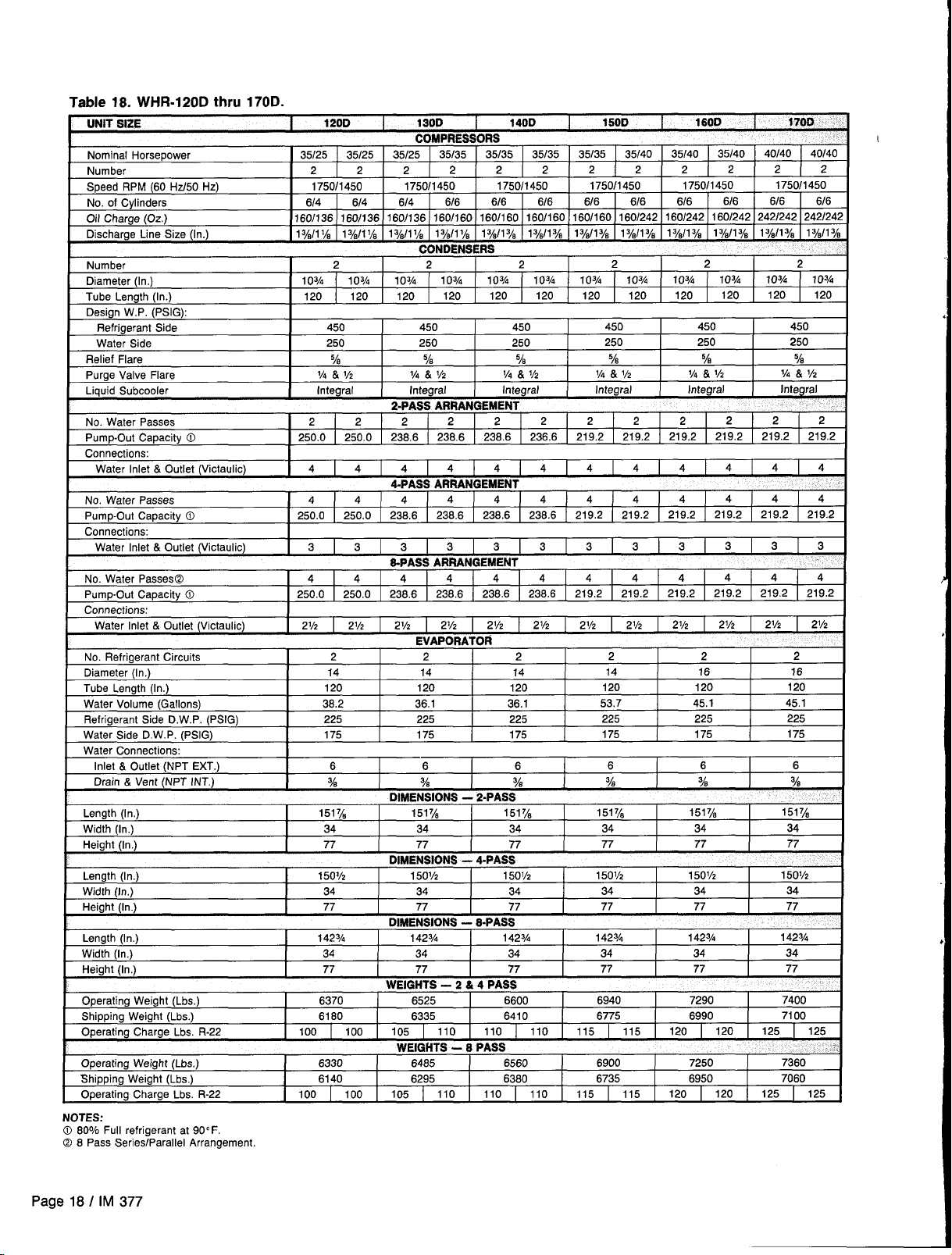
Table 18. WHR-120D thru 170D.
UNIT SIZE
120D
1
130D 140D
COMPRESSORS
Nominal Horsepower
Number
Speed RPM (60 Hz/50 Hz)
No. of Cylinders
Oil Charge (Oz.)
Discharge Line Size (In.)
Number
Diameter (In,)
Tube Length (In.)
Design W.P, (PSIG):
Refrigerant Side
Water Side
Relief Flare
Purge Valve Flare
Liquid Subcooler Integral
No. Water Passes
PumpOut Capacity 0
Connections:
Water Inlet & Outlet (Victaulic)
No. Water Passes
Pump-Out Capacity @ I 250.0
I
Connections:
Water Inlet & Outlet (Victaulic)
160/1 36 160/136 160/1 36 160/1 60 160/1 60
I
I
I
35/25 35/25 35/25
2 2 2 2
1750/ 1450
6/4 6/4 614
1%111A 1y*ll 1/3 12/8/11A
2 2
103~ liJ3~ lrJ3~ 1133~
120 120 120
450 450 450
250 250 250
% 5/8
V4 & V2
2 2 2
250.0 250.0
4 4 4
4 4 4
3 3 3
2-PASS ARRAN QEMENT
238.6 238.6 238.6 236.6
4-PASS ARRANGEMENT
250,0 238,6
35135 35135 35/35 35/35 35/40
2 2
1750/1 450
6/6
1yJl 1A
CONDENSERS
120 120
V4 & V2 V4 & V2
Integral
2 2
4 4 4
4 4 4 4 4
238,6 236,6 236.
3 3 3 3 3 3
1750/ 1450 1750/ 1450
6/6 6/6 6/6 6/6 6/6
160/1 60 160/160 160/242
1%/1 ye
13/Jl Ya
2
1034 103~ f 03~ I03/4
1133~
I
120 120 120
5/8
Integral Integral Integral
2 2 2 2
6 219.2 219.2
S-PASS ARRANGEMENT
No. Water Passes@
PumpOut Capacity @ 250.0 250.0
Connections:
Water Inlet & Outlet (Victaulic)
No. Refrigerant Circuits
Diameter (In,)
Tube Length (In.)
Water Volume (Gallons) 38.2 36.1 36.1
Refrigerant Side D.W.P. (PSIG)
Water Side D.W.P. (PSIG)
Water Connections:
Inlet & Outlet (NPT EXT.) 6 6 6
Drain & Vent (NPT INT.)
Length (In.)
Width (In,)
Height (In.) 77 77
t nla*EM@lnNe
Length (In.)
Width (In,)
Mainht (In 1 77 77 77 77 77 77
,,“, =,!. ,, !!.,
4 4 4
I
21/2
2 2 2
14 14 14
120 120 120
225 225 225
175 175 175
% %
1517/~ 1517/8
I
34 34 34
I
150% t501/2 150Vz
34 34 34
,,
1
238.6 236.6 238.6 238.6 219.2
21/2 21/2
DIMENSIONS - 2-PASS
“,!wE,.e,”$.” — .rr””!
1
4 4 4
21/2 21/2
EVAPORATOR
,,
1
21/2
3/8
151y~ 1517/8
77
I
A-CI&~s
,,
DIMENSIONS - 8-PASS
Length (In.)
Width (In,)
Height (In,)
142s%
I
34 34 34
77 77 77
I
14234
142% 142%
WEIGHTS -2 & 4 PASS
Operating Weight (Lbs.)
Shipping Weight (Lbs.) 6160 6335
Operating Charge Lbs. R-22
6370 6525
100 100 105
110 110 110
6600 6940 7290
6410 6775 6990
WEIGHTS -6 PASS
Operating Weight (Lbs.) 6330 6485
Shipping Weight (Lbs.) 6140 6295
Operating Charge Lbs. R-22 100 100
NOTES:
0 60°/0 Full refrigerant at 90” F.
@ 8 Pass Series/Parallel Arrangement.
105 110 110 110 115 115
6560 6900 7250
6380 6735 6950
150D 160D
35/40 35/40
2 2 2
1750/ 1450
160/242 160/242 242/242 242/242
1%11%
1%11%
I %1~%
2 2
120 120
450 450 450
250 250 250
=% %
X4 & Y2
219.2 219.2
4 4 4
4 4 4
219,2
Y4 & V2
219.2 219.2 219.2 219.2
4
219.2
219,2 219.2 219.2 219.2
21/2 21/2 .21/2
2 2
14
120 120
53.7
225 225
175 175
6
%
34 34
77 77
15ol/z
34 34
. .
1
34 34
77 77
115
115 120 120
16 16
45.1
6 6
Y8 %’s
I
1517/8
1507/2
. .
1
142?4
120 120 125 125
2 2 2
6/6 6/6 6/6
1%11ye 13/”11Vi 12/!!11ye
103~ 103/4
2 2 2
4 4 4
4 4 4
219.2 219.2
3 3 3
4 4 4
21/2 21/2 21/2
170D .
40/40 40/40
1750/1 450
120 120
7/4& V2
Integral
120
45.1
225
175
1517/~
34
77
150%’
34
.,
1
142%
34
77
7400
7100
125 125
7360
7060
2
103~
I
%
,.
219.2
2
.,
Page 18 I IM 377
Page 19

Figure 16. Compressor Locations
UNITS 040D thru 11OD
t
n
1
1
,
cOMP.
G
.J–
I
\
\
\
SUCTION
PIPING
Table 19. Contactor Designation
1
1
CONTROL BOX
COOLER
‘–
COMP,
2
I
k
n
I
UNITS 120D thru 170D
t
I
\
I
SUCTION
PIPING
n
I I
CONTROL aOX
!
n
I
1
I
Two contractors are used per compressor on all 208 volts units. Two
NOTE:
contractors are also used on THR-090—I 10 all voltages, and on all 460 & 575
part winding start units.
IM 377 I Page 19
Page 20

WIRING
FIELD WIRING, POWER
The THR TEMPLIFIERS are built standard with compressor
contractors and power terminal block, designed for single
power supply to unit. Optional power connections include a
non-fused disconnect switch mounted in the control box or
multi-point power connection.
A factory installed control circuit transformer is available
as an option with single power supply or disconnect switch;
it is not available with multi-point option.
Optional circuit breakers are available for backup compressor short circuit protection on 040D thru 110D units and
are standard on all four (4) compressor units 120D thru 170D.
Wiring and conduit selections must comply with the National Electrical Code and/or local requirements.
FIELD WIRING, CONTROL
Control circuits on all units are designed for 115 volt operation. A separate source of 20 amp, 115 volt AC power may
be brought to terminals 1 and 14 (terminal 14 on the ground
side) to power the control circuit. On 208 volt power, leads
from any line and neutral of the 208 volt system may be
brought to terminals 1 and 14 to provide 120 volts to the control circuit.
An optional factory mounted transformer is available to pro-
vide the correct control circuit voltage. All models include the
An open fuse indicates a short, ground, or overload. Before
replacing a fuse or restarting a compressor or fan motor, the
trouble must be found and corrected. Tables in the Electrical
Data section give specific information on recommended wire
sizes.
Unit power inlet wiring must enter the side of the control
box (right side) through an inlet hole provided for field terminating conduit. (Refer to control panel layout drawings for
general location of power inlet and components.)
WARNING: Use only copper conductors in main terminal
block. If the power input conductors are aluminum, use a compression splice to change to copper before terminating in
block.
necessary factory wiring to power the transformer.
On models THR-040D thru 170D the transformer power
leads are connected to the power block PBI or disconnect
switch DS1.
Six 1/2° conduit knockout openings are provided for field
wired options and are located on the left side of the control
panel when facing the unit control panel doors.
NOTE: See page 51 for additional information on the con-
trol thermostat.
INTERLOCK WIRING
The control arrangement shown on the wiring diagram will
permit continuous or cycling operation of the source water
pump. Provision has been made to permit source water pump
cycling by the addition of a field supplied relay “MA” and
wiring it between terminals 11 and 16. if relay “MA” is not
added the pump must be wired for continuous operation.
When continuous source water circulation is used, the flow
switch contacts should be tied into the control circuit as shown
on the interlock schematic (see Figure 17).
The condenser water pump must be arranged for con-
tinuous water circulation, otherwise leaving condenser water
– PUMP STARTERS
temperatures will not be properly controlled.
Condenser water flow switches must be wired into the control circuit as shown on the interlock schematic and depending on the application it may be necessary to install a time
delay relay with timed open contacts connected into the control circuit in parallel with the flow switch to prevent nuisance
tripping.
Whenever the application will permit, continuous water circulation in both the source water and condenser water circuits is preferred and the use of flow switches in both circuits is recommended.
Page 20 I IM 377
Page 21

Figure 17. Typical Interlock Schematic
NOTE: FOR SINGLE STARTER APPLICATION, JUMPER TERMINAL 11 AND 12 AND WIRE STARTER BETWEEN 11 AND 16.
PHASE
3
POWER SUPPLY
UNIT DISCONNECT
SWITCH(BY OTHERS)
rt
Ml
—7
I
L
M2
I
COMP.
#1
COMP.
#3
@!&d
-2
M3 CB1
—
I
l——
I
I
1
2
S1 CONTROL
~
(b
()
()
RELAY
1~-
R9
IQ--U–––––-J
RIO
4 CONTACTS 11
41
r——x
——
--M~i=~
41
Al
I
1
I
120V
UNIT OPERATING
CONTROLS(CKT. 1)
I OPTIONAL CONTROL
I CKT. TRANSFORMER
COMP
#2
COMP.
.U4
15
NB
LEGEND
@
—— .
——— —
I)
71
5
TIMECLOCK
CONTACTS
6
EVAPORATOR
FLOW SWITCH
7
8
NOTE: For single starter application, jumper terminal 11 and 12 and wire starter between 11 and 16.
FIELD CONNECTION TERMINAL
FACTORY WIRING
FIELD WIRING
OPTIONAL FACTORY WIRING
Ml—MB COMPRESSOR CONTRACTORS
CB1—CB4
PB1
MA, MB
UNITOPERATING
CONTROLS(CKT.2)
TEMPLIFIERUNIT
CAPACITYCONTROLS
1
COMPRESSOR CIRCUIT BREAKERS
UNIT POWER TERMINAL BLOCK
CONDENSER PUMP STARTERS (MAX. 20VA EA.)
NB
NB
IM 377 I Page 21
Page 22

SEQUENCE OF OPERATION – THR-040D thru 110D
The following sequence of operation is typical for THR
TEMPLIFIER HEAT PUMP, models THR-040D thru
THR-110D. The sequence varies somewhat depending upon
options.
HEAT ONLY OPERATION
Compressor Heaters
and the control stop switch S1 open, 115V power is applied
through the control circuit fuse F1 to the compressor
crankcase heaters HTR1 and HTR2.
Startup —
power is applied to the compressor motor protectors MPI and
MP2 and the primary of the 24V control circuit transformer.
The 24V transformer provides power to the central processor
thermostat CPI and to the optional alarm bell.
When the remote time clock or manual shutdown switch
turns on the water pump, the flow switch closes and 115V
power is applied to the relay contacts on the central processor
CP1. The unit will automatically operate in response to the central processor CP1 provided the manual
pumpdown switches PSI and PS2 are closed (in the auto
position), the compressor lockout time delays TD1 and TD2
have closed, energizing the safety relays R5 and R6, and the
freezestats FS1 and FS2, high pressure controls HPI and
HP2, and compressor motor protectors MPI and MP2 do not
sense failure conditions.
On a call for heating, the central processor CP1 energizes
the liquid line solenoid SV1 for refrigerant circuit #1, opening the valve and allowing refrigerant to flow through the expansion valve and into the evaporator. As the evaporator
refrigerant pressure increases, the low pressure control LPI
closes. This energizes the compressor contractors M1 and
M5, starting the compressor. Also, R9 relay is energized. R9
relay is wired to terminals providing a means for interlocking
the pump starter, MA with the compressor operation. See
page 21 for pump control.
As additional stages of heating capacity are required, the
central processor CPI energizes the liquid line solenoid valve
SV2 of refrigerant circuit #2. After the compressor sequencing time delay TD11 has closed, the same starting sequence
is initiated in refrigerant circuit #2.
If additional heating is still required, the central processor
will de-energize the unloader solenoids of each compressor,
respectively.
HEATING/COOLING OPERATION
Heat/cool units are designed to supply hot water for heating
needs and to allow switching to cooling operation when it is
needed.
The sequence of operation for combination heating/cooling units is similar to heating only, the difference is in the
thermostat arrangement. On heat/cool models the heating
thermostat “CPI” is still used, but in conjunction with a
changeover switch and the addition of a separate cooling thermostat “CP2”. Changeover from heating to cooling operation or cooling to heating is accomplished by setting the
changeover switch for the desired mode to activate the
desired heat or cool thermostat. The thermostat relay con-
tacts then activate the control circuit whenever compressor
operation and/or loading or unloading is required to satisfy
the thermostat setting for the mode selected.
The heating thermostat controls the leaving hot water
temperature leaving the condenser through a sensor located
in the return water to the condenser.
Conversely the cooling thermostat controls the water
temperature leaving the evaporator through a sensor located
in the return water, to the evaporator temperature selection
With the control stop switch S1 closed, 115V
— With the control circuit power on
dials inside the thermostats, are used to set the desired leav-
ing water temperatures for either heating or cooling. Seethe
thermostat bulletin packed with the unit for additional
information.
Check the applicable 4 or 6 stage heat/cool wiring diagrams
starting on page 39 for specific wiring details.
Pumpdown Cycle System Shutdown — As the central pro-
cessor is satisfied, it will unload the compressors and then
de-energize the liquid line solenoid valves SV1 and SV2,
causing the valves to close, starting the pumpdown cycle.
When the compressor has pumped most of the refrigerant
out of the evaporator and into the condenser, the low pressure
controls LPI or LP2 will open, shutting down the compressors. During the off cycle, if a closed solenoid valve allows
refrigerant to leak into the evaporator, the increase in
pressure will cause the low pressure control LPI or LP2 to
close. This will energize the compressor contractors Ml and
M2 and start the compressor, which will quickly pump the
refrigerant out of the evaporator and into the condenser
(recycling pumpdown).
A compressor which repeats recycling pumpdown every
5 minutes indicates a malfunction due to the temperature control or a system cause. A buildup of heat in the compressor
without proper cooling of suction gas could cause a
mechanical failure in the compressor. McQuay recommends
corrective measures be taken if the compressor recycles
repeatedly within 15-minute intervals.
Safety Relay Operation —
be energized to permit normal operation. If the freezestats
FSI and FS2, high pressure controls HP1 and HP2, oil
pressure controls OP1 and 0P2 or compressor motor pro-
tectors MP1 and MP2 sense a fault condition and open, the
safety relay R5 or R6 will be de-energized. The relay contacts open and de-energize the compressor contactor and
the liquid line solenoid valve.
Compressor Anti-Short Cycle Time Delay — The unit is
equipped with 5-minute time delay relays TD1 and TD2 which
provide anti-short cycling protection. When low pressure control LP1 closes and energizes Ml compressor contactor, LP1
also energizes R9 which provides power to auxiliary relay MA
for control of a starter for a remote evaporator pump. A second contact on R9 shunts out TD1 opening up TDI. When
LPI opens, cutting power to R9, then compressor #1 cannot
be started until TD1 times out and energizes safety relay R5.
Operation of LP2, TD2, M2, R1O and R6 is similar for opera-
tion of the second compressor.
Note: The motor protector in the compressor terminal box
has a 2-minute time delay. When power is interrupted to terminals 3 and 4 of any motor protector, the MP contacts between MP terminals 1 and 2 open and will not close for two
minutes.
Indicator Lights —
with indicator lights to show the status of electrical control
operation.
1:
ON-STOP Switch — Has an inherent light which glows
when the control circuit is energized.
2.
Lights SV1 and SV2 — Glow when the safety relays are
energized indicating compressor circuit safety contacts are
closed, and compressor will operate in response to CP1
thermostat.
Lights RLI and RL2 — Glow when the compressor con-
3.
tractors are energized and cooling circuit is in operation.
4.
Heating Stage Indicator Lights — Red lights next to the
relays on the main central processor thermostat indicate
which heating stages are energized.
The safety relays R5 and R6 must
The THR unit control box is equipped
Page 22 I IM 337
Page 23

SEQUENCE OF OPERATION – THR-120D thru 170D
The following sequence of operation is typical for THR
TEMPLIFIER, models THR-120D thru THR-170D. The se-
quence varies somewhat depending upon options.
Compressor Heaters
— With the control circuit power on
and the control stop switch S1 open, 115V power is applied
through the control circuit fuse FI to the compressor
crankcase heaters HTRI, HTR2, HTR3, and HTR4.
Startup — With the control stop switch S1 closed, 115V
power is applied to the compressor motor protectors MP1,
MP2, MP3, and MP4 and the primary of the 24V control circuit transformer. The 24V transformer provides power to the
central processor thermostat CP1 and to the optional alarm
bell.
When the remote time clock or manual shutdown switch
turns on the water pump, the flow switch closes and 115V
power is applied to the relay contacts on the central processor
CP1. The unit will automatically operate in response to the
central processor CP1 provided the manual pumpdown switches PS1 and PS2 are closed (in the auto position), the compressor lockout time delays TD1 and TD2 have closed,
energizing the safety relays R5 and R6, and the freezestats
FSI and FS2, high pressure controls HPI and HP2, and compressor motor protectors MP1, MP2, MP3, and MP4 do not
sense failure conditions.
On a call for heating, the central processor CP1 energizes
the liquid line solenoid SVI for refrigerant circuit #1, opening the valve and allowing refrigerant to flow through the
expansion valve and into the evaporator refrigerant pressure
increases, the low pressure control LPI closes. This
energizes the compressor contractors Ml and M5, starting
the compressor. Also, R9 relay is energized. R9 relay is wired
to terminals providing a means for interlocking the pump
starter MA with the compressor operation.
As additional stages of capacity are required, the central
processor CP1 energizes the liquid line solenoid valve SV2
of refrigerant circuit #2. After the compressor sequencing time
delay TDI 1 has closed, the same starting sequence
is initiated in refrigerant circuit #2.
If additional heating is still required, the central processor
will activate additional cylinders on the lead compressor of
each system or activate compressors #3 and #4, depending
on the load requirements and the capacity control stops
available on the unit.
Pumpdown Cycle System Shutdown — As the central pro-
cessor is satisfied, it will cut off compressor #4 and #3, then
unload compressors #2 and #1, and finally de-energize the
liquid line solenoid valves SV1 and SV2, causing the valves
to close. When the compressor has pumped most of the
refrigerant out of the evaporator and into the con-
denser, the low pressure controls LP1 or LP2 will open, shutting down the compressors. In the event a closed solenoid
valve allows refrigerant to leak into the evaporator, the increase in pressure will cause the low pressure control LPI
or LP2 to close. This will energize the compressor contractorsMl and M2 and start the compressor, which will quickly
pump the refrigerant out of the evaporator and into the condenser (recycling pumpdown).
A compressor which repeats recycling pumpdown every
5 minutes indicates a malfunction due to the temperature control or a system cause. A buildup of heat in the compressor
without proper cooling of suction gas could cause a
mechanical failure in the compressor. McQuay recommends
corrective measures be taken if the compressor recycles
repeatedly within 15-minute intervals.
Safety Relay Operation —
The safety relays R5 and R6 must
be energized to permit normal operation. If the freezestats
FSI and FS2, high pressure controls HPI and HP2, oil
pressure controls OP1 and 0P2 or compressor motor protectors MP1 and MP2 sense a fault condition and open, the
safety relay R5 or R6 will be de-energized. The relay contacts open and de-energize the compressor contactor and
the liquid line solenoid valve. Safety relays
R7 and R8 pro-
vide a similar function for compressors #3 and #4.
Compressor Anti-Short Cycle Time Delay — The unit is
equipped with 5-minute time delay relays TD1, TD2, TD3 and
TD4 which provide anti-short cycling protection. When low
pressure control LPI closes and energizes Ml compressor
contactor, LPI also energizes R9 which provides power to
auxiliary relay MA for control of a starter for a remote pump.
A second contact on R9 shunts out TD1 opening up TD1.
When LP1 opens, cutting power to R9, then compressor #1
cannot be started until TDI times out and energizes safety
relay R5.
Operation of LP2, TD2, M2, RIO, R6 and Ml is similar for
operation of the second compressor.
Note: The motor protector in the compressor terminal box
has a 2-minute time delay. When power is interrupted to terminals 3 and 4 of any motor protector, the MP contacts between MP terminals 1 and 2 open and will not close for two
minutes.
Indicator Lights —
The THR unit control box is equipped
with indicator lights to show the status of electrical control
operation.
1:
ON-STOP Switch — Has an inherent light which glows
when the control circuit is energized.
2.
Lights SW, SV2, SV3, and SV4 — Glow when the safety
relays are energized indicating compressor circuit safety
contacts are closed, and compressor will operate in
response to CP1 thermostat.
3.
Lights RL1, RL2, RL3, and RL4 — Glow when the compressor contractors are energized and cooling circuit is in
operation.
4.
Heating Stage Indicator Lights — Red lights next to the
relays on the main central processor thermostat indicate
which heating stages are energized. Note: Located inside
control box.
377 / Page 23
IM
Page 24

Table 13. Compressor motor amp draw
--.,
,Uqw
4 . . .
‘.
---- ,: 230 162 202 1070
‘,
.:. .,.
11OD
J6VV
. .
“:14.90
.,.I?ww
:..,-,
..:.
.. z,-- 230 113.129 113.129 565.594
:9700: ,,
..-
230
460 Q
I
I 4600 I 53 I 61 I 235
575
I
208
208
I
208
230 202 202 1070
460 Q 101 101
I
1 460 Q I 61, 42 I 61, 421283,214
208
230 113, 113 113, 113 565,565
460 D 61, 61 61, 61 283.283
I
4600 I 61, 61 I 61, 651283,263
I
206
I
230 129, 129 129, 129 594, 594
460 ~ 65, 65 65, 65 297, 297
575 52, 52 52, 52 235, 235
77
42 42
I
I
I
I
113, 113 113, 113 565, 565
I
113, 153 113, 153 565, 660
I
45 45
153
I
162
I
202
I
153
202
202
428
214
172
428
428
214
172
565
565
283
230
565
565
283
230
660
594
297
235
1070
1070
535
405
1070
1070
535
405
1070
1070
535
405
-
orAfly9 ,
:&%$i;,:#)
~&&it:
T
186
84
61
250
-a--4-E
250
117
103
292
292
141
130
mm
340
340
156
138
400
w
340
170
135
654
654
330
262
654
654
330
262
654
654
330
262
340, 250
340, 250
156, 117
136 103
340, 250
340, 250
156, 117
138 103
340, 340
340, 340
156, 156
138 138
340, 340
340, 340
156, 156
138 138
-
340, 400
340, 340
156, 170
138, 135
400, 400
340, 340
170, 170
135, 135
mm
140, 340
156.156
ERiT
38, 135
100, 400
i40, 340 548
70, 170 I 276
35, 135 I
250
117 95
I
170
135
I
654
654 365
I
330
262 135
654
654
330 208
I
I
146
117 65
365
165
415
415
460
259
207
650 344
221 117
173
96
53
39
96
96
53
I
81
203
203
I
103
75
203
203
103
I
254
137
I
110
290
146
I
96
53
+
39
141
141
76
56
141
141
76
56
7
191
161
81
65
203
203
103
75
253
253
126
90
253
253
126
90
218
218
118
87
254
254
137
101
254
254
137
101
304
274
142
110
304
274
142
110
344
290
146
117
I
T5?i(
&i,?!!,:
circuit3
T
77
I
I
428
214
230
660
1070
I
1070
535
I
i65, 426
i65, 426
?83, 214
?30, 172
j65, 428
i65, 426
?83, 214
?30 172
;65, 565
;65, 565
I
!83, 283
!30, 230
;65, 660
i65, 660
!83, 297
!30, 235
i65, 660
i65, 594
!63, 297
!30, 235
;60, 660
’94, 594
’97, 297
’35, 235
NOTES:
@ ALLOWABLE VOLTAGE LIMITS:
Unit Nameplate 208V/60Hz/3Ph: 187V to 253V (except THR-080D: 180V to 220V).
Unit Nameplate 230V/60Hz13Ph: 187V to 253V (except THR-080D: 207V to 253V).
Unit Nameplate 460V/60Hz/3Ph: 414V to 506V.
Unit Nameplate 575V/60Hz/3Ph: 517V to 633V.
Unit Nameplate 380V/50Hz/3Ph: 342V to 418V.
Compressor RLA values are for wire sizing purposes only and do not reflect normal operating current draw
Compressor LRA for Dart windina starl are for the first windina,
Unit tire size amm a;e eaual to 725V0 of the Iaraest comoress~r-motor RLA DIUS100VO of RLA of all other loads in the circuit includina control transformer.
Wire size amps ;or separate 115V control circu~ power (s 10 amps.
Single point power supply requires a single fused disconnect to supply electrical power to the unit.
Multiple point power supply requires three independent power circuits with separate fused disconnects (two compressor circuits, one control circuit).
Data also applies to 380V/50Hz/3Ph units.
page 24 I IM 377
Page 25

CONTROL CENTER
All electrical controls are enclosed in a control center with
Iocking, hinged access door(s). A partition separates the adjustable safetv controls from the starting and operating con- justable controls are covered and can be adjusted without
trols. A “deadfront” panel covers all starting and operating
CONTROL CENTER LAYOUT, THR-040D thru 11OD
Figure 18. Left Side, 115V Control Section
controls so that no electrical contacts or terminals are exposed. The deadfront panel is hinged for servicing. The ad-
fear of contacting line voltage.
Figure 19. Right Side, High Voltage Control Section
u
——
-cmiP, ——— —————
TR HM
lx)
TB4(110–124,210-224)
r
B
n
CP2
!4604
IPS1 82
I
ElljallI
F1 PS2CTR HM
_ ~c)
TD
I
11
❑
1
D
~————.
mmlmlma
TB6(70-93)
I
RACEWAY
TB2 (1—16) I TB3 (17-28) 1
Figure 20. Left Side, 115V Control Section
~~m
CONTROL CENTER LAYOUT, THR-120D thru 170D
PVM
T2
nu
EIEIEIEI
I
LOOKING AT THE BACK
NOTE
CIRCUIT
BREAKER
SWITCH
POSJTP3N
ON
?)
“d
OFF
L
Figure 21. Right Side, High Voltage Power Section
OF THE CONTROL PANEL 1
/
!!$$
.7’
n
!1
.
ALARM BELL
/
T1
AB1
:~
CTR HM
mi:l’:~
T84 1110–1240,210-2241
I
I
CTR HM I PSI S2
RACEWAY
A
‘---=iBT@’l@
1
❑ml-’l ❑ m+
RACEWAY
t-
NB
0
EIOGRD
I
n
PVM
u
‘mmmm-
NOTES:
PBI and PB2 are used with multiple point power wiring.
1.
2. Circuit breaker8 are provided as an option, on THR-040D—110 units,
IM 337 I Page 25
Page 26

ELECTRICAL LEGEND
DESIGNATION DESCRIPTION
AB Alarm Bell
CB1–6
COMPR. 1—4 Compressorsl —4
CP1
CP2
CTR 1—4
DS1
F1
FB5
FS1 , 2
GFI
GRD
HM7–4
HP1 , 2
HTR1–4
LP1 , 2
Ml–8
FAA, MB
MJ
MP1–4
NB
OL1–6
OP1–4
PB1, 2
Psi, 2
PVM
RI, 2
R3, 4
R5–8
Circuit Breakers Compr, Motors
Central Processor
Central Processor Satellite, CoollHeat Control Box
Counter Compr. Total Hours
Disconnect Switch Main
Fuse Control Circuit
Fuaeblock Control Power
Freezestats, Pressure Control
Ground Fault Interrupter
Ground
Hour Meter Compressors
High Pressure Controls
Heaters, Compressor Crankcase
Low Pressure Controls
Contactorsr Compressor
Pump Starter Coils
Mechanical Jumpers
Motor Protectors, Compressor
Neutral Slock
Overloads
Oil Pressure Controls
Power @lock, Main
Pumpdown Switches
Phaae Voltage Monitor
Relays, Alarm
Relays, Starting
Relays, Safety or Alarm
STANDARD LOCATION
Back or Side of Control Box
Control Box
Top of Evaporator
Control Box
Control Box
Control Box
Control Box
Control Box
Control Box
Control Box
Control Box
Control Box
Control ❑ox
On Compressor
Control Box
Control Box
Field Installed
Control Box
Compressor Junction Box
Control Box
Control Box
Control Box
Control Box
Control Box
Control Box
Control Box
Control Box
Control Box
DESIGNATION
R9–12
R13, 14
R17, 18
R21, 22
R23, 24
R25–30
RL1–4
RRM
S1
S2
SD1
SL1–4
Svl, 2
SV5. 6
T1
T2
TB2
TB3
TB4–6
TC1
TC1O
TC1l
TC12
TD1–4
TD5–6
TD1l–13
TD20–24
Ul, 2
DESCRIPTION STANDARD LOCATION
Relays, Starting
Relays, Low Ambient Start
Relays, Capacity Control
Relays, High Return/Low Source Water
Relays, Unloader Control
Relays, Special
Run Indicator Lights
Remote Reset Module
Switch, Control Stop
Switch, Lead-Lag
Solenoid Door Lock
Safety Indicator Lights
Solenoid Valves, Liquid Lines
Solenoid Valves, Hot Gas Bypass
Transformer, Main Control
Transformer, 23V Control
Terminal Block, 120V Field
Terminal Block, 24V Field
Terminal Blocks, Controls
Thermostat, Special
Thermostat, Special
Thermostat, Low Source Water
Thermostat, Special
Time Delays, Compressor Lockout
Time Delays, Compressor PW Start
Time Delays, Compressor Sequencing
Time Delays, Special
Unlosders
Control Box
Control Box
Control Box
Control Box
Control Box
Control Box
Front of Control Box
Control Sox
Side of Control Box
Control Box
Control Box
Front of Control Box
On Liquid Piping
On Hot Gas Piping
Control Box
Control Box
Control Box
Control Box
Control Box
Control Sox
Control Box or On Unit
Control Box
Control Box or On Unit
Control Box
Control Box
Control Box
Control Box
On Compressors
1. ———— FIELD WIRING
2. —–-—
3, —. —-—
4.
—200— WIRE NUMBER
WIRING IN REMOTE UNIT
WIRING CONNECTING UNITS
5 ~ O’T’ON “OC”
6.—(— FACTORY WIRED TERMINAL
GENERAL NOTES
7.
—o—
8.
—@—
9 ~
10.—<+ PLUG CONNECTOR
11,
289 ‘
OPTIONAL LINEON TERMINAL BLOCK
FIELD WIRED TERMINAL
REMOTE PANEL TERMINAL
WIRE CONNECTOR
Page26/lM337
Page 27

THR 040D THRU 080 D–SINGLE POINT 380/415/575V – AL, PW
11
:~~
1,
[i-+-q ~~ ,
~“‘“3/ SET
I
~“ ;T:~
L --- - -.
GRLO:: D
‘1
—
TYPICAL POWER WIRING DIAGRAMS
.-
‘- ‘ ‘cl
4t
( )
,,o&---.–.7
5314:; ‘“M i
532-+.l_.i
PHA;:,J13~RAGE
-—.—. ~
—
I
I
CB2
101
102
[03
CBI
!d/A ON uINTS
380/415 /460 fi75V AL
M2
104
105
106
107
108
109
110
!11
1[2
,.,
,2,
II
,,
~,, ,2JFS5
.
8
TO CO NT ROl-
TRANSFORM ER-TI
~380 V./5O-6O HZ. ]
[415 ‘/./50 HZ.
I
N/A (,N uINTS
380/4 i5j463fi75V AL
460 V./6O HZ.
1
1
113
H4
115
575 V./6O HZ.
IM 377 I Page 27
Page 28

THR 040D THRU 080 D–SINGLE POINT 208/230 – AL, PW
-L.
—
-H-
+
I ~–
ii
I
!1
53’ +---l
PHASE $OL:,16E
MO PIITOA
101
102
103
r
IG4
!05
106
107
108
109
77
110
Ill
112
—.
Lz
05
TZ<,
—-
TO COtJTROL
TRANSFORMER-T1
113
114
1,5
Page 28 I IM 377
Page 29

THR 090D THRU 11OD–SINGLE POINT 208/230 & 380/41 5/460/575 – AL, PW
_ i.
—
I
—
101
102
103
104
105
106
—
—
—,
IL
11
107
(08
109
I
7
8
9
\
110
Ill
112
-W: OMPR,
●2
7
10
&
-B5
II
&
12
89
113
114
115
‘OcOTROL rgmTRANSFORM ER-TI
IM 377 I Page 29
Page 30

THR-040D THRU 11OD—MULTIPLE POINT 380141514601575V — AL, PW
NO. I
I
I
I TI i, T3
PB2
GND
LUG
~
PB I
TI T,
.
—
—
—
____ .—-=
530 +OLl
53 -+’ ‘v’” ~
I
532-b-L2—-_i
lJliS1:.&OL T AGE
—
—
r
I
.2
3
4
5
>
6
CO~~R.
7
21
89
LlltE
No.
101
102
103
104
105
106
107
108
/’-’-
— N/A ON THR040D-080D UNITS
WITH 380/415 /’46O/’575V - AL
—
~. N/A ON 1HR040D-080D UNITS
NOTES :
PBI S PB2 ARE OMITTED ON 380/415 /460/575V
FOR UNIT SIZES WHR040-080D WHEN OVERLOAD OPTION 1S NOT USED.
FIELD CONNECT CIRCUIT NO. I DIRECTLY TO Ml CONTACTOR ANO CIRCUIT 2 TO
M2 CONTACT OR.
- AL IACROSS LINE START I UNITS,
WITH 380/’4l5/46Ofi75V - AL
7
8
9
10
II
—’
12
10
II
12
115
Page 30 I IM 377
Page 31

ELECTRIC E:;RCJ: +C
CIRCUIT
NO. 2
I
I
.-
I
—
NO.
I
THR-040D THRU 11OD– MULTIPLE POINT 208/230V – AL, PW
53o +Ll
53’ +’-2 ‘“MI
532 +-LI-J
~#f;EROL TAGE
If
101
102
103
r
_—_ —--
~.
bq-
L-—-—. -.-J
I-—-—-___-i
1
2
3
4
5
6
7
8
9
104
105
106
[07
108
109
i10
Ill
112
10
II
12
113
114
!15
IM 377 I Page 31
Page 32

THR-120D THRU 170D–SINGLE POINT 380/41514601575V – AL, PW
N/A ON THR 120D, 130D’
FROM D51 E PBI
— ,2
,1
I
r, 12
—
,,
“1 .3 “2 H4
!3J
—
~’”’ey<o
I ,,5
\
- N/A ON THR 120D.
—,20—
—,2(—;::
—122—
—130—
—,3, —
—13*—
— ,33 —
Page 32 I IM 377
Page 33

“. ., . .
THR-120D THRU 170D–SINGLE POINT 208/230V – AL, PW
. .
.,m!.
.
.. ,,
..—
,m..:~.
~~:.—
,,!
“..,,,,,, !..,
r..
“m,
B
,
N
.. ..
.,.,,, ,. ,., , . .. . .
<:~: ‘“‘=E:>
THR-120 THRU 170D–MULTIPLE POINT 2081230V & 380141514601575V – AL, PW
,(<.:,, . ,
.,
!.. . .. . .
.,,. . ,. . .
. . . .
.,, #—
.,,
.
- ,,..
..,, -
.,,, —
!.
,,.V.
r Ya-,,..
~“” +
l--’+
!,,,,
,-,,,.,
“WI T,.
G
.,
:E:,
‘W ,
,.”., ,
.,
,,’, ~
<
M,
., ,,
‘k+ ..
%%,m.:.2L--
~
;$,,
,,,.
,,
“W .,
co.,, .
.,
..’
,.
G”’
GE51
“i+ :.
*J
./.. ......
s,.,, . .. . .. ..,,.
—,.,.
_,,..:*
–,-!1:
.,, ,—
.,,..r.
.,,, .:::
IM 377 I Page 33
Page 34

TYPICAL CONTROL & SAFETY WIRING DIAGRAMS
THR-040D THRU 11OD
L, 1~:’’:}:‘a-jJ
%
14
F
100
*I
106
MJ
—-.
so
/)
MJ45
I
b
,.
$~’g:;”+–––+$––––+$-5’2–
2.;’~2.+
MI-NIX
l---#2~,~,
,37g13*:llo&lll~ 18y{l#~122&.J
r
COMPRESSOR
c! RcUIT
I
COMPRESSOR
CIRCUIT
[ SEE REFRIGERATION SCHEMATIC I
NOTE : FOR EVAPORATOR WATER PUUP CYCL lNO
WITH COUPSESSORS.
+~~EL10WIW~lP$122, sTASTER BETWEEN
)lTR-1
UP1
I12
197
INqERm’
TIME CSLAY
I
●[
NIA ON 0400 THRU OeOD
380/415/4607575 v. u.
LP2
I
-++ 2,4 &5 77?l++#+317
‘“n’
●2
m
& 235 +X+:=
143
“,:$&kiJ:
++.
105~126–
153
j-m
FS2 ‘ ‘
———
54 ml
22
to ~
,=
N/A ON 040D THRU 0000
380/415/460/575 V. AL
,my ,
/*’ \
/\
28
c1 C2
3 106
———
~8 ,,0 C2 23C
1
152-
252
M
-2GG -
B
-201 -
B
-202
-
-203 -
-204 —202 —
— 206 -
-207 -
B
-209 -
—210 -
—211 —
— 212 -
n
— 220 —
-221 -
- =2 — ::
B
— 223 - 204
B
— 224 -
B
— 225 - 222
-226 - 222
B
— 227 —
B- *** - ~
8
— 229 -
-230 -
>
— 231 - :2:
-232 — 108
-233 -
I
— 245 - 317
b
—243 - 321
I
-260 -
-261 —
— 262 — 266.314
, — 263 — 206
,—264 —
I
— 265 - 262
-266 — 262
B
-267 -
I
— 268 - ;:,
I
-269 — 270 —
1
— 2?1 - ::!
’272 - !14
-273 -
T32
5G2dG3
4 5C’6,5C4
Ho
3 240
lm,144 4 m2sG7
5 2GG
6 303510
7 510,522
B 324J70
9
10
II 142
!2 242
13
M 514
15
16 512
1
515 ~ 107,207
88 518
670 19 100,208
20
21
22
23
?4
2s
26
27 516,671
?. 519
1
785
40 187,160
100 41 137.186
42 l10,13e
43
44 113,114
4s 135
64CJ 63 146,150
129,154 +7 115,116
118 43 111,112
49 In
123,127 50 1=,~
128 51 12+,125
52
53
54
55
5s
57
S3
5s
60
61
62
63
I
7! 287280
200 71 237
72 210,22S
73
213,214
~ 235
6s0 76 266,320
229,2s4 77 215.216
218 78 211,212
222 79
223,337 @ X5~
228 81 224.235
?3
84
85
86
8?
36
09
m
91
92
93
1
NO
0 :?:J;3
o /::152
O [&641
O 199,243
0 206,253
0 236,651
0 247,28S
o
0
182,196
0 282,2%
O 185,285
0
1
Page 34 I IM 377
Page 35

THR-120D THRU 170D
FI
—,40
-“’*.’’”~’’”+&-
COMPRESSOR
CIRCUIT ●I
COMPRESSOR
CIRCUIT*3
FSl
,,,,
M1-AUX
,0;:., “2 ‘
-,;TTJ~”_,
HTR-I
23
qiy
—,20 ”/60,, —
,1
?------’’k--g
. .
,>, ,—.
‘ ,20.
— *m-
-
—,., —
?++’--’
+
)
COMPRESSOR
Cl RCUlT#2
cOMPRESSOR
CIRCUIT*4
I
II
,,,
219
8s 4,
1
,
.
J
L
;4ZI
—--M
*7. —*O?
,,, —
27.—;;:
*T7 —
,,, —
,,, –;:;
,,, —,2
*, I —
—?7.
,,,
m,
,1,
.(.
:;;:.
H “iiv
y:~,.,.
.,,,,
4,, ,0 .,,
:;1, ,, .,.
92
93
!
IM 377 I Page 35
Page 36

TYPICAL HEATING ONLY THERMOSTAT WIRING DIAGRAMS
4-STAGE HEATING ONLY THERMOSTAT—THR 040, 050, 060, 070, 080, 090, 100, 11 OD
,
J@?.sA
,,”0”,.,.,, .,0, m,
T
509 “510 10 t“S1.LL TIME
,,0,, ,$40 ,... SWITCH
m.,.crs.
s
1
L+.J
I
1!
‘1
R,,.!
274
c ,,
“4 *,6
Hot Gas Bypass and Phase/Volt Monitor Options
NB
-304 -
—30. —
~~~’c’”~”
—,07—
-310—22,
-311—
—,,2—
-3,3—
—,!4 —
-3,5—
—,16-265
-,1, —
-,,.—
-,19 -
I
290
+.2,
2
2“e,,,.,—t,~.
u,
-,20 -
-,2!—
-3a-
-,2, -
4-STAGE HEATING ONLY THERMOSTAT—THR 120, 130, 140, 150D
Hot Gas Bypass and PhaseNolt Monitor Options
TB4
I10
,7, ,,, 33!
,,2 y::
370 ,,3 !::
,,3. , ,4 ;:J
,,4. _
I ,5
1,6
,,7
;j I ,8
,,9 357
,73
Im ::;
(2,
!22
!,3
,24
2,0
,73 2,, 55.
2,2 :::
.70 2,3 ;EI
,93. ,,4 ;:J
284. _
271
,,2 2!5
2)6
,(7
,,,
:;;
4,, 2,9 5.,
~ ::
221
222
223
224
Page 36 I IM 377
Page 37

m
,,..”, .,.,, .,0, ..0
.,,0 ,. ,.,,.,, ,!.,
.,.,. ,., ,,..
s.
,.”,,,,
6-STAGE HEATING ONLY THERMOSTAT–THR 070, 080, 090, 100, 11OD
Hot Gas Bypass and Phase/Volt Monitor Options
,.,,,.
I
.,..”
;;; =
‘
L
c “(
REM,
.,
,77
L
c “(
,,,.”
“’-t%
!.,4
, ,,,.
:., /
,,,, .,, ,,
,,,
,,/
.<, ,.
.,l. —
.,l, —
.,,6 —,6,
.,,7 —
.,,8 —
320-
.321—
322—
,24-
3,5—
,“4
I ,.,
‘,’ ,,, .,?’
.,y,
,,,
:;; ,,, ::
r.
!. ,a,:,:
,,.,
,..,,.
“, ,:;’
:,;: ,, ,,.
,,’,
,2,,
,,,
,22
,23
,24
2,0
,>, .
,,0
2(,
334
212
;::
*,.
,,0 2!3 ;:L
2,3*
~,, ;:&
;;:,
27!
*~~~,,6
2,7 :
j:.
;;? ,,8 279
219
zm
221
222
223
224
Inmi
..”0”,.!”, s .S0S AN.
“,10 70 !“SIUL 1!.,
5;9
,,0.. .“0 FLOW $W8TC”
m“r.crs .
6
1
510
6-STAGE HEATING ONLY THERMOSTAT–THR 120, 130, 140, 150, 160, 170D
Hot Gas Bypass and Phase/Volt Monitor Options
,,
,,,*—Y
L
2“v0LTsAc519~28
_J
.1
-304—
-,os —
—,07—
-,!0—2,,
—,11—
-312—
—,,, —
-,,, —
-3(5—
–,,s —265
-,17—
–,,, —
-31, —
-,20—
.,2, —
.322—
-323-
-32.—22,
-32,—269
Page 38

6-STAGE HEATING ONLY THERMOSTAT—THR 120, 130, 140, 150, 160, 170D
.. .
Hot Gas Bypass and Phase/Volt Monitor Options
10‘z~.,[iG3&”~p
, , , W,,,* ,,”. .,”,,,
271+272
>:2’32“ “4 :: ‘ 5“%2’’=2”- 2“ 2’”:2”
274
Q
,74
,,0
,,3
T
‘ 2 5522,6 .<+7
,;
,,0
:+ R21
,,1
-+
PvM
e
.,
! 70 17(—551
2,0
~,% ‘“-3 ,7, ‘:6 ,y;
*
II
7
533~~534
PH/VOLT MONITOR
.,..., MJ-
e!’
..”.,
, .0
*7G.2
.,” “2 ,,, TD,,
< NO
ST. “,
c MC
‘B?3lMM-
—303—
—3.4—
—3., -
I
—
306—
—,07—
—3!.—,25
—3\l —
“::,j~::,f’’’~~~:;;a”a” :::
!,
“’2&2,z:2
.6, -j&69
T
‘ -d
‘t’” ‘ ‘“’ ‘w’”’ z ‘“4 =:=
T
—314—
—,, ,—
—3,6-,8,
-3!7—
TB4
rml
[’
Ml-EL2“
275—2%~5%i ‘ “ Y “ ‘ “’2”4 -’2’-
~’”JR7=-’20-
Page 38 I IM 377
Page 39

TYPICAL HEAT/COOL THERMOSTAT WIRING DIAGRAMS
4-STAGE HEATICOOL THERMOSTAT–THR 040, 050, 060, 070, 080, 090, 100, 11OD
Hot Gas Bypass and Phase/Volt Monitor Options
m
=
-3m--
-344-
-3n-
-97-
.m8--
.312-
.3!+
.3!4-
.30..8cn7-
.*
ns-
-
m-
TM
11
In
11
11
11
1
lZ
1
1
12
2!
~
SI
n
2s!
Ss
WE
—-mn?s.cmm.mm
p#61#LT:&nE m
I
4-STAGE HEATICOOL THERMOSTAT—THR 120, 130, 140, 150D
Hot Gas Bypass and Phase/Volt Monitor Options
1
1
I 1
I
I
I
I
,,e~
47n
I I
I
Ill
‘Yl,!cmtrw’
I
IzE3
-
LuJ-
N!
‘m
39—
-344-
-
3s,—
-397-
-w,-
.3! 2—
.313-
.314—
.3!s-
.31#-
m —
.94- m
.324A-
TB4
22!
2
22
2?.
11
11
11
!1
121
12
12
12
21
21
a
La
IM 377 I Page 39
Page 40

6-STAGE HEAT/COOL THERMOSTAT–THR 070, 080,090, 100, 110D
Hot Gas Bypass and Phase/Volt Monitor Options
M.=
-w7-
k9-
-x2-
-n >
-a4-
-m*
-nc-
-n7—
-a-
6-STAGE HEATICOOL THERMOSTAT—THR 120, 130, 140, 150, 160, 170D
Hot Gas Bypass and Phase/Volt Monitor Options
,274
%#”lHi?
m
-93-
-94-
-m7-
--
-n2-
-.3-
-.+
-.5-
-n+
-.9-
Page 40 I IM 377
-=+-m
-324a-
-3K- m
-mM-
Page 41

8-STAGE HEATICOOL THERMOSTAT—THR 120, 130, 140, 150, 160, 170D
Hot Gas Bypass and PhaseNolt Monitor Options
~85!-.&.- .95,4
129V. ,69 man Snmx
“77-+-%’’3+’7’-
6
I
AIR RESET DIAGRAM
F,
1
5m
6
I
810
i I
IMzk=--.J
Ii
R$!f”
274
277 r. w 27s—
1-l
k
216
l—
— ,,,
‘JJ
;& R21
I I
w,. h,.
,,~,,,~
I17
-“’, Ill ““’
m
LINE CONT.
&
-3R-
-3m-
-9t-
--
-m-
-,, * a
-,, ,-
-3, *
—,,*
-Y, +
-a18-
—s,* -
-m7-
—m9-
-m-
--
-9t-
IM 377 I Page 41
Page 42

Table 23. Drawing Reference Decision Table for Compressor Power Schematics.
NOTE: Each unit will have three electrical schematics: Power, Safety & Control, and Thermostat.
THR
UNIT
SIZE
040 THRU 080D
DRAWING
NUMaER
705192D-01
SINGLE
MULTIPLE
POINT
380141514601575V
380141514601575V
I
2081230V
080, 100,1IOD
120 THRU 170D
040 THRU 11OD
120 THRU 11OD
040 THRU 11OD
I
120 THRU 170D
1
705191D-01
583403D-01
705190D.01
7051911-1-o1
583402D-01
705198D-01
583404D-01
705199D-01
583404D-01
I
Table 24. Drawing Reference Decision Table for Control and Safety Schematics.
Page 42 I IM 377
.
UNIT
SIZE
040 THRU 110D
120 THRU 170D
DRAWING
NUMBER
706219D-01
583435D-01
Page 43

Table 25. Drawing Reference Decision Table for Heating Only Thermostat Control Schematics.
DRAWINGNO.
WITHOUT
I
THR
uNIT
SIZE
OUTOOORAIR
OR LOW
SOURCE
wATER RESET
583171C-02
WITH
1 CIRCUIT
583172C-02
58335L7C-02
+$=$=
I
8
583362C-02
563167C-02
583342C-02
563168C-02
563356C-02
‘H
I
ZERO OR 2 CIRCUITS
I
WITHOUT 6
I
120 – 170D
8
4 040 – 11OD
070- 11OD
120- 170D
120- 170D
8
D4O-11OD
4
120- 150D
I
O7O-11OD
120-1700
120-1700
8
583360C-02
583169C-02
583170C-02
583357C-02
563361C-02
583165C-02
583341C-02
583166C-02
563355C-02
583359C-02
DRAWINGNO.
WITH
OUTOOORAIR
OR LOW
SOURCE
WATER RESET
551515C-OIC
551519C-01
551525C-01
551529C-01
551513C-01
551521C-01
551517C-01
551523C-01
551527C-01
551514C-01
551516C.01
551524C-01
551528D-01
551512C-01
551520C-01
551516C-01
551522C-01
551526D-01
1 CIRCUIT
I I
ZERO OR
2 CIRCUITS
WITHOUT
wITH
4
040- 11OD
070 – 11OD
120- 170D
s
8 120- 170D
4 040-1100
070- 11OD
8 120–170D
4
040-1100
O7O-11OD
120– 170D
563163C-02
563164C-02
583346C-02
563350C.02
563159C-02
563340C-02
563160C-02
583344C-02
563348C-02
563161 C-02
583162C-02
583345C-02
583349C-02
563157C-02
563339C-02
563156C-02
563943C-02
563347C-02
IM 377 I Page 43
Page 44

Table 26. Drawing Reference Decision Table for Heat/Cool Thermostat Control Schematics.
WITH
1 CIRCUIT
+=$==
DRAWINGNO. DRAWINGNO.
WITHOUT
OUTOOORAIR OUTOOORAIR
THR
UNIT
SIZE
I
OR LOW
SOURCE
wATER RESET WATER RESET
551533C-01
551537C-01
551543C-01
@
551531C-01
551539C-01
551535C.01
551541C-01
WITH
OR LOW
SOURCE
(D
o
0)
@
o
0
(D
‘e
I
a
551532C-01
551536C-01
551542C-01
120- 170D
I
8
120- 170D
8
@
551530C-01
55T538C-01
551534C-01
551540C-01
Q
563163C-02
583164C-02
563346C-02
583350C-02
563159C-02
5~3340C-02
563160C-02
583344C-02
0
@
@
551544C-01
5515461=01
551545C-01
551547C-01
NOTES:
1. For units with reset diagrams not listed contact McQuay Service.
2. Diagrams for 8-stage heat/cool units are as follows:
● Unit application: 583455D-01
● Remote control panel with outdoor air/low source water reset: 551576D-01
● Remote control panel without reset: 551570D-01.
44 I IM 377
Page
1
563346C-02
563161 C-02
563162C-02
563345C-02
120- 170D
I
8
B 120- 170D
563349C-02
563157C-02
583339C-02
563156C-02
583943C-02
563347C-02
Page 45

STARTUP AND SHUTDOWN
I
PRE STARTUP
1. With the main disconnect switch open, check allelec.
trical connections in control panel and starter to be sure
they are tight and provide good electrical contact.
Although connections are tightened at the factory, they
may have loosened enough in shipment to cause a
malfunction.
2. Check and inspect all water piping. Make sure flow direction is correct and piping is made to correct connection
on evaporator and condenser.
3. Open all water flow valves to the condenser and
evaporator.
4. Flush the cooling tower (when used) and system piping.
Start evaporator pump and manually start condenser
pump and cooling tower. Check all piping for leaks. Vent
the air from the evaporator and condenser water circuit
as well as from the entire water system. The evaporator
circuits should contain clean, non-corrosive water.
5. If water regulating valves are provided, connect the control capillary to the manual valves provided on the condensers and open the manual valves.
6. Check to see that the water temperature thermostat sensor is installed in the entering water line to the condenser.
7. Making sure control stop switch S1 is open (off) and
STARTUP
1. Open the compressor suction and discharge shutoff
valves until backseated. Always replace valve seal caps.
2. Open the manual liquid line shutoff valve.
3. Check to see that the unit circuit breakers are in the “off”
position.
4. Check to see that the pumpdown switches PS1 and PS2
are in the “manual pumpdown” position and the con-
trol system switch S1 is in the “off” position.
5. Throw the main power and control circuit disconnects
to the “on” position.
6. Verify crankcase heaters have operated for at least 12
hours prior to startup. Crankcase should be warm. in the refrigerant sightglass.
7. Adjust the dial on the temperature controller to the
pumpdown switches PSI and PS2 are on “manual
pumpdown,” throw the main power and control discon-
nect switches to “on. ” This will energize crankcase
heaters. Wait a minimum of 12 hours before starting up
unit.
8. Check compressor oil level. Prior to startup, the oil level
should cover at least one-third of the oil sightglass.
9. Check water pressure drop across evaporator and condenser, and see that water flow is correct per the
pressure drop data on pages 7 and 10.
10. Check the actual line voltage to the unit to make sure
it is the same as called for on the compressor nameplate
within + 10% and that phase voltage unbalance does
not exceed 2%. Verify that adequate power supply and
conductor size is available to handle load.
11. Make sure all wiring and fuses are of the proper size.
Also make sure all interlock wiring connections are com-
pleted per McQuay diagrams.
12. Verify that all mechanical and electrical inspections by
code authorities have been completed.
13. Make sure all auxiliary load and control equipment is
operative and that an adequate cooling load is available
for initial startup.
desired hot and/or chilled water temperature.
8. Start the auxiliary equipment for the installation by turning on the time clock, ambient thermostat and/or remote
on/off switch and chilled water pump.
9. Check resets of all safety controls.
10. Switch the unit circuit breakers to on.
11. Throw pumpdown switches PSI and PS2 to “auto” for
restart and normal operation.
12. Start the system by pushing the system switch S1 to on.
13. After running the unit for a short time, check the oil level
in each compressor crankcase, and check for flashing
After system performance has stabilized, it is necessary that the ‘‘Compressorized Equipment Warranty Form”
(Form No. 206036A) be completed to obtain full warranty benefits. This form is shipped with the unit and after
completion should be returned to McQuayService through your sales representative.
WEEKEND OR TEMPORARY SHUTDOWN
Move pumpdown switches PSI and PS2 to the “manual
pumpdown” position. After the compressors have pumped
down, turn off the evaporator water pump. NOTE: With the
unit in this condition, it is capable of recycling pumpdown.
To defeat this mode of operation, simply move control system
STARTUP AFTER TEMPORARY SHUTDOWN
1. Start the evaporator water pump.
2. With the control system switch S1
move the pumpdown switches PSI
pumpdown” position.
in the “on” position, sounds or possible cycling of compressors.
and PS2 to the “auto
switch S1 to the “off” position.
It is important that the compressors pump down before the
water flow to the unit is interrupted to avoid freeze-up in the
evaporator.
3. Observe the unit operation for a short time, noting unusual
4. Check compressor crankcase heaters.
IM 377 I Page 45
Page 46

EXTENDED SHUTDOWN
1. Close the manual liquid line shutoff valves.
2, After the compressors have pumped down, turn off the
chilled water pump.
3. Turn off all power to the unit.
4. Move the control service switch S1 to the “off” position.
5. Close the suction and discharge shutoff valves on the compressor(s) and the liquid outlet valve(s) at the condenser(s)
STARTUP AFTER EXTENDED SHUTDOWN
1.’ Inspect all equipment to see that it is in satisfactory
operating condition.
2. If cooling tower is used, make sure it is clean and filled
with water.
3. Open the compressor suction and discharge valves until backseated. Always replace valve seal caps.
4. Open the manual liquid line shutoff valves.
5. Check circuit breakers. They must be in the “off”
position.
6. Check to see that the pumpdown switches PSI and PS2
are in the “manual shutdown” position and the control
system switch S1 is in the “off” position.
7. Throw the main power and control circuit disconnects
to the “on” position.
8. Allow the crankcase heaters to operate for at least 12
hours prior to startup.
9. Start the chilled water pump and purge the water piping
6. Tag all opened disconnect switches to warn against startup before opening the compressor suction and discharge
valves.
7. Drain all water from the unit evaporator and chilled water
piping if the unit is to be shut down during the winter and
exposed to below freezing temperatures.
as well as the evaporator in the unit.
10. Start the auxiliary equipment for the installation by turning on the time clock, ambient thermostat and/or remote
on/off switch.
11. Adjust the dial on the temperature controller to the
desired hot and/or chilled water temperature.
12. Check resets of all safety controls.
13. Switch the unit circuit breakers to “on,”
14. Start the system by pushing the system switch S1 to
“on. ” CAUTION: Most relays and terminals in the con-
trol center are hot with S1 and the control circuit discon-
nect on.
15, Throw pumpdown switches PSI and PS2 to the “auto
pumpdown” position for restart and normal operation.
16. After running the unit for a short time, check the oil level
in each compressor crankcase and for flashing in the
refrigerant sightglass (see Maintenance section).
Page 46 I IM 377
Page 47

SYSTEM MAINTENANCE
To assure smooth operation at peak capacity and to avoid
damage to package components, a program of periodic inspections should be set up and followed. The following items
are intended as a guide to be used during inspection and
must be combined with sound refrigeration and electrical
practices to assure trouble-free performance.
The liquid line sightglasslmoisture indicator on all circuits must be checked to be sure the glass is full and clear
and the moisture indicator indicates a dry condition. If the
indicator shows that a wet condition exists or if bubbles show
in the glass, even with a full refrigerant charge, the filter-drier
element must be changed.
Water supplies in some areas may tend to foul the water
cooled condenser to the point where cleaning is necessary.
The fouled condenser will be indicated by an abnormally high
condensing pressure and may result in nuisance tripouts. To
clean the condenser, a chemical descaling solution should
be used according to the manufacturer’s directions.
CONTROL CENTER ELECTRICAL SERVICE
The electrical control center is relatively easy to service since
indicator lights are provided to show unit status. Determine
that the problem is actually in the control panel before
proceeding.
By referring to the schematic wiring diagrams, the trouble
can be isolated to a particular section of the panel.
WARNING: Warranty is voided if field wiring is not in accordance with specifications. A blown fuse or tripped protector
indicates a short ground or overload. Before replacing a fuse
or restarting a compressor, the trouble must be found and
corrected. It is important to have a qualified control panel electrician service this panel. Unqualified tampering with the con-
trols can cause serious damage to equipment and void the
warranty.
GENERAL
A lead-lag switch
models to permit even distribution of wear on the compressors. This switch should be turned on on an annual basis.
The compressor oil /eve/ must be checked periodically
to be sure the level is at the center of the oil sightglass. Low
oil level may cause inadequate lubrication and oil failure
switch tripout. If the oil level is low and oil must be added,
use oils referred to in “Compressor Oil Level” section below.
A pressure tap has been provided on the liquid line
downstream of the filter-drier and solenoid valve but before
the expansion valve. An accurate subcooled liquid pressure
and temperature can be taken here. The pressure read here
could also provide an indication of excessive pressure drop
through the filter-drier and solenoid valve due to a clogging
filter-drier.
NOTE: A normal pressure drop through the solenoid valve
is approximately 3 psig at full load conditions.
The following steps should be taken prior to attempting any
service on the control center:
1. Study the wiring diagram so that you understand the
operation of the TEMPLIFIER.
2. Before investigating trouble in the control center, check
for burned out pilot lights by testing across the appropriate
terminals.
CAUTION: The panel is always energized to ground
even though the system switch is off. If it is necessary to
de-energize the complete panel including crankcase
heaters, pull main disconnect.
If motor or compressor damage is suspected, do not restart
until a qualified serviceman has checked the unit.
is provided on all multiple compressor
ELECTRICAL TERMINALS
CAUTION: Electric shock hazard. Turn off all power before continuing with following service.
All power electrical terminals should be retightened every six months, as they tend to loosen
in service due to normal heating and cooling of the wire.
COMPRESSOR OIL LEVEL
The oil level should be watched carefully upon initial startup
and for sometime thereafter.
At the present time, Suniso No. 3GS, Calumet RO15, and
Texaco WF32 oils are approved by Copeland for use in these
compressors. The oil level should be maintained at about onethird of the sightglass on the compressor body.
Oil may be added to the Copeland compressor through the
oil fill hole in the crankcase. To add oil, isolate the crankcase
and pour or pump in the necessary oil. If the system contains
no refrigerant, no special precautions are necessary other
than keeping the oil clean and
dry.
If the system contains a refrigerant charge, close the suc-
“tion valve and reduce crankcase pressure to 1 to 2 psig. Stop
the compressor and close the discharge valve.
Add the required amount of oil. During the period the com-
pressor is exposed to the atmosphere, the refrigerant will
generate a vapor pressure, retarding the entrance of contaminants. Before resealing the compressor, purge the
crankcase by opening the suction valve slightly for 1 or 2
seconds. Close the oil port, open the compressor valves and
restore the system to operation.
IM 377 I Page 47
Page 48

REFRIGERANT SIGHTGLASS AND MOISTURE INDICATOR
The refrigerant sightglasses should be observed period- pressure drop in the line, possibly due to a clogged filter-drier
ically. (A monthly observation should be adequate.) A clear or a restriction elsewhere in the system. An element inside
glass of liquid indicates that there is adequate refrigerant
the sightglass indicates what moisture condition corresponds
charge in the system to insure proper feed through the ex- to a given element color. If the sightglass does not indicate
pansion valve. Bubbling refrigerant in the sightglass indicates a dry condition after about 12 hours of operation, the unit
that the system is short of refrigerant charge. Refrigerant gas
should be pumped down and the filter-driers changed.
flashing in the sightglass could also indicate an excessive
LEAD-LAG
A standard feature on all McQuay TEMPLIFIERS is a system
for reversing the sequence in which the compressors start.
quence is compressor #2, then compressor #l. It is achieved electrically by multi-pole switching arrangement (see “Con-
For example, on a unit with the lead-lag switches in the “cir- trol Schematics” on pages 38 through 40). It is suggested
cuit 1 leads” position, the normal starting sequence is com- that the lead-lag switches in the unit control center be swit-
pressor #l, then compressor #2. With the lead-lag switches ched annually to provide even compressor life.
in the “circuit 2 leads” position, the reversed starting se-
CRANKCASE HEATERS
The compressors are equipped with crankcase heaters. The When a system is to be started up initially in cold ambient,
20 hp and larger model compressors have heaters inserted the power to the heaters should be turned on for some time
into the crankcase. The function of the heater is to keep the
temperature in the crankcase high enough to prevent
refrigerant from migrating to the crankcase and condensing
in the oil during off-cycle.
(at least 12 hours) before the compressor is started. The
crankcase should be up to about 80” F before the system is
started up, to minimize lubrication problems or liquid slugging of compressor on startup.
Page 48 I IM 377
Page 49

SYSTEM SERVICE
NOTE: Service on this equipment is to be performed by qualified refrigeration personnel. Causes for repeated tripping of safe-
ty controls must be investigated and corrected.
CAUTION: Disconnect all power before doing any service inside the unit.
FILTER-DRIERS
To change the filter-drier, pump the unit down by moving
pumpdown switches PSI and PS2 to the “manual pumpdown” position.
UNITSIZE
040D THRU 170D
NOTE:Jumpersshouldbelongenoughtohangoutofthepanelandprevent
the door from closing. This will insure jumper removal after unit is
pumped-down.
Move the control switch S1 to the “off” position. Turn off all
power to the unit and install jumpers across the terminals
shown in the table. This will jump out the low pressure control. Close the manual liquid line shutoff valve(s). Turn power
The liquid line solenoid valves, which are responsible for
automatic pumpdown during normal unit operation, do not
normally require any maintenance. However, in the event of
failure they may require replacement of the solenoid coil or
of the entire valve assembly.
The solenoid coil may be removed from the valve body
without opening the refrigerant piping by moving pumpdown
switches PSI and PS2 to the “manual pumpdown” position.
CIRCUITNO.
1 44 to 48
2 74 to 78
JUMPERACROSS
TERMINALS
LIQUID LINE SOLENOID VALVE
to the unit back on and restart the unit by moving the control
switch S1 to the “on” position. The unit will start pumping
down past the low pressure setting. When the evaporator
pressure reaches Oto 5 psig, move control switch S1 to the
“off” position. BE SURE TO REMOVE THE JUMPER.
Frontseat the suction line King valve(s). Remove and
replace the filter-drier(s). Evacuate the lines through the liquid line manual shutoff valve(s) to remove non-condensables
that may have entered during filter replacement. A leak check
is recommended before returning the unit to operation.
THR UNIT SIZE
040 thru 1IOD
120 thru 170D 2 — Core Replaceable
NOTE: On Arrangement A units, the filter-drier cores are shipped in the unit
control box and are to be installed prior to evacuating and charging the unit.
The coil can then be removed from the valve body by simply
removing a nut or snap-ring located at the top of the coil. The
coil can then be slipped off its mounting stud for replacement.
Be sure to replace the coil on its mounting stud before returning pumpdown switches PSI and PS2 to the “auto pump-
down” position.
To replace the entire solenoid valve, follow the steps in-
volved when changing a filter-drier.
TYPE FILTER-DRIER
Sealed Core
THERMOSTATIC EXPANSION VALVE
The expansion valve is responsible for allowing the proper
amount of refrigerant to enter the evaporator regardless of
cooling load. It does this by maintaining a constant superheat.
(Superheat is the difference between refrigerant temperature
as it leaves the evaporator and the saturation temperature
corresponding to the evaporator pressure.) All TEMPLIFIERS
are factory set for between 80 F and 120 F superheat, at leaving source water temperatures near the maximum allowed,
superheats can be expected to rise above this setting. If it
is necessary to increase the superheat setting of the valve,
remove the cap at the bottom of the valve to expose the ad-
justment screw. Turn the screw clockwise (when viewed from
the adjustment screw end) to increase the superheat and
counterclockwise to reduce superheat. Allow time for system
rebalance after each superheat adjustment.
Unit operation near the maximum leaving source water
temperature on a TEMPLIFIER unit can trigger the “Max-
imum Operating Pressure” (MOP) characteristic built into the
units expansion valves. At higher leaving source water
temperatures and loads, the “MOP” will occur when the ex-
pansion valve and control bulb pressure reaches a predeter-
mined maximum value. Further increases in bulb temperature
above the “MOP” point causes virtually no increase in bulb
pressure. As a result adequate increases in refrigerant flow
to the evaporator are no longer possible, and the ability of
the unit to handle increases in load is limited. Once the
“MOP” for the expansion valve is reached. increases in suction superheat can be expected
source water temperature.
near the maximum leaving
The expansion valve, like the solenoid valve, should not
normally require replacement, but if it does, the unit must
be pumped down by following the steps involved when changing a filter-drier.
If the problem can be traced to the power element only,
it can be unscrewed from the valve body without removing
the valve, but only after pumping the unit down.
WARNING: Adjustment of expansion valve should only be
performed by a qualified service technician.
Figure 22.
Inlet
~, :..
li7r-
‘“ I,.,,,,. .._.(contains ‘iaphragm)
~.. ,
/ . . . ... ...
p(l-1
>
ik
i!!li!z
Power Element
Outlet
Adjustment Screw
Cap
IM 337 I Page 49
Page 50

EVAPORATOR
The evaporator is of the direct expansion, shell-and-tube type
with refrigerant flowing through the tubes and water flowing
through the shell over the tubes. The tubes are internally
finned to provide extended surface as well as turbulent flow
of refrigerant through the tubes. Normally no service work
is required on the evaporator. There may be instances where
a tube will leak refrigerant into the water side of the system.
In the cases where only one or two tubes leak, the problem
can best be solved by plugging the tube at both ends. When
the tube must be replaced, the old tube can be removed and
replaced.
To remove a tube, the unit should be temporarily pumped
down. Follow the steps involved when changing a filter-drier.
These steps will insure a minimum amount of refrigerant loss
when the evaporator is opened up. The tubes are mechan-
ically expanded into the tube sheets (see Figure 23) at each
end of the cooler. In order to remove the tubes, it is necessary
to break this bond by collapsing the tube. After doing this
at both ends of the shell, the tube can be removed for replacement. The new tube can then be inserted and re-expanded
into the tube sheet.
NOTE:
The bond produced by expansion must be refrigerant
tight. This bond must be produced by applying Locktite (red)
to the tube and rolling it into the tube sheet.
After re-assembling the evaporator, a small amount of
refrigerant should be introduced by momentarily opening the
manual liquid line valve. A leak check should then be performed on the evaporator.
Tube removal can only take place after the leaking tube
is located. One method that would work would be to subject
each tube to air pressure by plugging each end and, with a
pressure gauge attached to one of the end plugs, observing
if there is a loss of air pressure over a period of a minute or
two.
Another method is to place a cork plug in each tube on
both ends of the cooler and applying pressure to the shell
of the cooler. After a period of time, the pressure will leak
from the shell into the leaking tube or tubes and pop out the
cork plug.
Figure 23.
Top View of Typical Dual Circuit Shell-and-Tube Evaporator
Liquid Connections
Suction Connections
k“ L
\\~
WATER COOLED CONDENSER
The condenser is of the shell-and-tube type with water flowing through the tubes and refrigerant in the shell. External
finned copper tubes are rolled into steel tube sheets. Integral
ti
II
L–
I r-
& ~~’r.ozzles ~
1
Water Baffles
II II
—.
[r
Refrigerant Tubes
Tube Sheets ~
11 11
1
I
‘T R
subcoolers are incorporated on 40 ton and larger units. All
condensers are equipped with 450 psig relief valves.
I
//
IN-WARRANTY RETURN MATERIAL PROCEDURE
COMPRESSOR
Copeland Refrigeration Corporation has stocking wholesalers
who maintain a stock of replacement compressors and service parts to serve refrigeration contractors and service
personnel.
When a compressor fails in warranty, contact your local
sales representative, or the McQuay International Warranty
Claims Department at the address on the back cover of this
bulletin. You will be authorized to exchange the defective
compressor at a Copeland wholesaler, or an advance replacement can be obtained. A credit is issued you by the wholesaler
for the returned compressor after Copeland factory inspection of the inoperative compressor. If that compressor is out
of Copeland’s warranty, a salvage credit only is allowed.
Page 50 I IM 377
Provide McQuay with full details; i.e., McQuay unit model and
unit serial numbers. Include the invoice and the salvage value
credit memo copies and we will reimburse the difference. In
this transaction, be certain that the compressor is definitely
defective, If a compressor is received from the field that tests
satisfactorily, a service charge plus a transportation charge
will be charged against its original credit value.
On all out-of-warranty compressor failures, Copeland offers the same field facilities for service and/or replacement
as described above. The credit issued by Copeland on the
returned compressor will be determined by the repair charge
established for that particular unit.
Page 51

COMPONENTS OTHER THAN COMPRESSORS
Material may not be returned except by permission of
authorized factory service personnel of McQuay International.
A “return goods” tag will be sent to be included with the
returned material. Enter the information as called for on the
tag in order to expedite handling at our factories and prompt
issuance of credits.
The return of the part does not constitute an order for
replacement. Therefore, a purchase order must be entered
through your nearest McQuay representative. The order
APPENDIX – STANDARD CONTROLS
NOTE: PERFORM AN OPERATIONAL CHECK ON ALL UNIT SAFETY CONTROLS ONCE PER YEAR.
THERMOSTAT—THR HEATING UNITS
should include part name, part number, model number and
serial number of the unit involved.
Following our personal inspection of the returned part, and
if it is determined that the failure is due to faulty material or
workmanship, and in warranty, credit will be issued on
customer’s purchase order.
All parts shall be returned to the pre-designated McQuay
factory, transportation charges prepaid.
The thermostats supplied on all Templifiers are factory
calibrated for use in the return water line to the condensers
inlet. The thermostat bulb is installed in a well in the return
water line in order to be more stable under temperature
changes due to load conditions. The return water does not
change temperature as rapidly as the outlet because of the
“flywheel effect” of the total water system. This results in
stable control of the outlet water temperature. Normally the
.
thermostat requires no adjustment in the field other than the
dial setting for the required control point. The control will maintain an average leaving water temperature corresponding to
dial setpoint (SPA) throughout the loading and unloading sequence of the unit. It should be realized, however, that there
cycles, unloads and loads.
The throttling range is adjustable from 1“F to 3° F per output relay via the TRA dial and is factory set at 3F. The control setpoint is adjustable from 120F to 150F via the SPA
dial and is field set to meet application. The ambient operating
temperature limits of the control is from 0F to 140” F.
Although the central processor CPI is calibrated at the factory, it may be necessary to re-calibrate the control should
any changes in unit operation be made in the field. Refer to
Installation and Maintenance Bulletin No. 348 for a more complete description of the control’s application, settings and ad-
justments, and checkout procedure. Note: See page 12 for
thermostat bulb installation.
will be fluctuation in the leaving water temperature as the unit
OIL PRESSURE SAFETY CONTROL
The oil pressure safety control is a manually resettable device
Figure 24.
which senses the differential between oil pressure at the
discharge of the compressor oil pump and suction pressure
inside the compressor crankcase. When the oil pressure
reaches approximately 15 psi above the crankcase suction
pressure, the pressure actuated contact of the control opens
from its normally closed position. If this pressure differential
cannot be developed, the contact will remain closed and
energize a heater element within the control. The heater element warms a normally closed bimetallic contact and causes
the contact to open, de-energizing a safety relay and breaking power to the compressor.
It takes about 120 seconds to warm the heater element
enough to open the bimetallic contact, thus allowing time for
Pressure Actuator
Contact
Line
Note 1
Line
Note 2
T2
Bimetallic COntaCtS
NOTES: 1 Hot only when the un,t thermostat calls for compressor to run
2 Hot onlv when other safety control contacts are closed
LM
Heater Element
1
I
*
Safety Relay
Neutral
the pressure differential to develop.
If during operation, the differential drops below 10 psi, the
heater element will be energized and the compressor will
stop. The control can be reset by pushing the reset button
on the control. If the compressor does not restart, allow a few
minutes for the heater elements and bimetallic contacts to
cool and reset the control again.
To check the control, pump down and shut off all power
to the unit. Open the circuit breakers or the fused discon-
nect for that compressor and install a voltmeter between ter-
minals L and M of the oil pressure control. Turn on power
to the unit control circuit (separate disconnect or main unit
disconnect depending on the type of installation). Check to
see that the control stop switch S1 is in the “on” position.
The control circuit should not be energized, but with the
absence of compressor power, no oil pressure differential can
develop and thus the pressure actuated contacts of the control will energize the heater element and open the bimetallic
contacts of the control within 120 seconds. When this hap-
pens, the safety relay is de-energized, the voltmeter reading
will rise to 115V, and the compressor contactor should open.
Repeated operations of the control will cause a slight heat
buildup in the bimetallic contacts resulting in a slightly longer
time for reset with each successive operation.
IM 377 / Page 51
Page 52

COMPRESSOR LOCKOUT
This feature locks out the compressor and prevents restart-
Figure 25. Compressor Lockout
ing for5 minutes after previous shutdown. The R9 relay is
de-energized with Ml and the normally open contacts 4 and
6 open in parallel with TD1. After 5 minutes, TD1 contacts 1
and 2 time close, permitting the R5 safety relay to energize
and Ml to close on a demand for cooling. As soon as the com-
pressor starts, R9 is energized and normally open contacts
4 and 6 close, bypassing TD1 contact, permitting normal
operation, The timer operation for the other compressor circuit is similar.
J-----qa---+--
NEUTRAL
LPI
—--%+’1
LINE
A
j
To check the control, the compressor must be running initially, Move the pumpdown switch PS1 or PS2 to the “manual
pumpdown” position. Immediately after the compressor has
stopped running, move the pumpdown switch back to the
“auto pumpdown” position. The compressor should not restart
for 5 minutes. Each refrigerant circuit can be checked the
same way,
Notes:
Line is only hot when freeze control and high pressure control permit safe
1.
operation
2. Line is only hot when oil pressure and compressor protection modules are
closed.
HIGH PRESSURE CONTROL
The high pressure switch will shut down the compressor and The water cooled condensers are supplied with a 450 psig
close the liquid line solenoid valve when the compressor
discharge pressure reaches 380 psig. To check the control,
slowly throttle the condenser inlet water or shut down the condenser fan. Observe the cutout point. During testing, stand
relief valve, After testing the high pressure control, check the
pressure relief device for leaks.
Caution: Although there isa pressure relief device in the
system set at 450 psig, it is highly recommended that the “con-
by the system switch to shut down the unit should the safety trol stop” switch S1 be close at hand in case the high pressure
device malfunction, Be sure the gauges used are accurate. control should malfunction.
LOW PRESSURE CONTROL
The low pressure control is a single pole pressure switch that
closes on a pressure rise. The control senses evaporator
pressure and must be set to suit unit application, refer to the
nominal low pressure setting table for approximate control setting. To check the control (unit must be running), move the
pumpdown switch(es) PSI and PS2 to the “manual pumpdown” position. As the compressor pumps down, the
evaporator pressure will drop. The lowest evaporator pressure
reached before cutout is the cutout setting of the control. Wait
for the compressor lockout time delays TD1 and TD2 to time
out, By moving the pumpdown switch(es) PS1 and PS2 to the
FREEZESTAT
The freezestat is a pressure type control connected to the low
side of the system and is set to shut down the system when
the pressure drops low enough to be dangerous as far as
cooler freeze-up is concerned. The control must be set to suit
unit application, refer to nominal freezestat setting table for
approximate control setting. When dropping to this point, the
normally open pressure actuated contacts of this control will
close, energizing a 115 volt heater. This causes the normally
closed bimetallic relay switch of this control to open after a
delay of approximately 60 seconds or less, stopping the com-
pressor and closing the liquid line solenoid valve. The time
delay prevents nuisance trip-out on momentary low suction
pressure and permits the operation of the system on a ‘pumpdown “cycle.”
The control must be checked while the system is operating.
To check the control, install a voltmeter or neon test light
Table 26. Nominal Low Pressure Cut-Out Settings
R-22 REFRIG.
Auto Reset
Note: Settings may vary from the nominal values shown to suit the particular
urmt application
LPI LP2
Cut-Out Press.
Reset Press. 60
35 psig
psig
“auto pumpdown” position, evaporator pressure will rise. The
highest evaporator pressure reached before compressor
restart is the cut-in setting of the control.
Table 27. Nominal Freezestat Pressure Settings
R-22 REFRIG.
52
Cut-Out Press
Reset Press.
I
Manual Reset
Note:
Settings may vary from the nominal values shown to suit the particular
unit application
I
FS1 , FS2
psig
57 psig
across terminal T1 and T2 of the low pressure freeze control.
There should be a voltage indication or the test light will glow,
indicating the contacts are opened. Throw the pumpdown
switch to the manual position and check the pressure at which
the test light goes out or the voltmeter goes to zero. In actual
operation, the compressor will shut down and the safety light
will go out. The control can be manually reset in about 2
minutes.
Page 52 / IM 377
Page 53

COMPRESSOR MOTOR PROTECTOR
The solid-state compressor motor protector module incor- Figure 26.
porates a 2-minute “time off” relay utilizing the bleed down
capacitor principle. Any time the protection system opens or
power to the module is interrupted, the 2-minute “time off”
delay is triggered, and the module will not reset for 2
rTIir7UteS. LINE ~~ “~
Once the 2-minute period is passed, the motor protector contacts 1 and 2 reset, provided the protection system is satisfied
and power is applied to the module.
APPENDIX – OPTIONAL CONTROLS
PART WINDING START (OPTIONAL)
MP1
——
rj ~I
4L--&~~:+
—
,.,
$,,,.,.
Part winding start is available on all units and consists of a
solid-state time delay wired in series with the contactor that
energizes the second winding of each compressor motor. Its
purpose is to limit current inrush to the compressors upon
startup. As each compressor starts, the contactor of the first
motor winding is delayed for 1 second.
Control checkout is best accomplished by observation as
each contactor is pulled in to see that the 1 second delay
occurs before the second contactor pulls in.
PHASE/VOLTAGE MONITOR (OPTIONAL)
The phase/voltage monitor is a device which provides pro-
tection against three-phase electrical motor loss due to power
failure conditions, phase loss, and phase reversal, Whenever
any of these conditions occur, an output relay is deactivated,
disconnecting power to the thermostatic control circuit. The
compressor will automatically pump down.
The output relay remains deactivated until power line con-
ditions return to an acceptable level. Trip and reset delays
have been provided to prevent nuisance tripping due to rapid
power fluctuations.
When three-phase power has been applied, the output relay
should close and the “run light” should come on. If the out-
ALARM BELL
Figure 27. Part Winding Start Option
Compr Contactor
Line
T
5---dk+-
Note: Line is only hot when the unit calls for compressor to run.
Pari W,nd,ng
Time Delay
[al Mol., W,nd, ”g,
(R2 Motor Wmd,.g)
put relay does not close, perform the following tests.
i.
Check the voltages between LI—L2, L1—L3-and L2—L3.
These voltages should be approximately equal and within
+ 10% of the rated three-phase line-to-line voltage.
2.
If these voltages are extremely low or widely unbalanced, check the power system to determine the cause
of the problem.
3.
If the voltages are good, turn off the power and interchange
any two of the supply power leads at the disconnect.
This may be necessary as the phase/voltage monitor
is sensitive to phase reversal. Turn on the power. The out-
put relay should now close after the appropriate delay.
(OPTIONAL)
Neulral
This option is available and is factory installed with a 24 volt
alarm bell which can be remotely mounted. The bell is wired
into the control circuit so that it will sound whenever there
is a failure due to an abnormal low pressure condition in the
evaporator, excessive head pressure, motor overheating or
low oil pressure. Page 25 shows location of bell in back of
the control box.
Figure 36. Alarm Bell Option
LINE
RI
1
,
4f
R7
R2
1
=+’
FS1
LINE
I*
-l
120V
~
24V
n
ALARM BELL
4
HP1 OPT MP1 RELAY
1-
A
1 lY
-fY
NEUTRAL
—
5AFETY
41
IM 377 / Page
53
Page 54

LOW SOURCE WATER UNOLADING CONTROL (OPTIONAL)
The low source water unloading senses the temperature of
evaorator return water and partially unloads one or both compressor circuits. The control has an adjustable OF to 100F
temperature range with 3° F switch differential.
The purpose of the control is to prevent overcooking the
source water, which will result in low suction pressure at the
compressor. Low suction pressure with the compressor at
full load could result in damage to the compressor. A setpoint
is recommended for the low source water thermostat of
HOT GAS BYPASS (OPTIONAL)
This option allows passage of discharge gas to the evaporator
permitting operation at lower loads than available with compressor unloading, It also keeps the velocity of refrigerant gas
high enough for proper oil return at light load conditions. A
solenoid valve in the hot gas bypass line is wired in parallel
with the compressor unloader U1. Thus, the hot gas solenoid
cannot open unless the compressor is operating in an unloaded mode. If only one hot gas valve is specified for the unit,
the hot gas bypass is wired in the first refrigerant circuit and
the lead-lag switches are therefore eliminated. The hot gas
bypass option is also available for the second refrigerant circuit whereby the lead-lag switches remain.
The pressure regulating valve is factory set to begin open-
ing at 58 psig (32”F for R-22). This setting can be changed
approximately 10° F to 15° F below the design return water
temperature. The unit is shipped from the factory with the
control sensor clamped to the side of the return water line
neat the cooler connection. (See Figure 7 page 12). To check
the control, the system should be operating at full load conditions. By slowly turning the dial setting up, the control should
partially unload one compressor circuit. By continuing to dial
the setting up, the second compressor circuit should unload
depending on what the interstage differential is set at.
by changing the pressure of the air charge in the adjustable
bulb. To raise the pressure setting, remove the cap on the
bulb and turn the adjustment screw clockwise. To lower the
setting, turn the screw counterclockwise. Do not force the ad-
justment beyond the range it is designed for, as this will
damage the adjustment assembly.
The regulating valve opening point can be determined by
slowly reducing the system load while observing the suction
pressure, When the bypass valve starts to open, the refrigerant
line on the evaporator side of the valve will begin to feel warm
to the touch.
Caution: The hot gas line may become hot enough to cause
injury in a very short time: care should be taken during valve
checkout.
Figure 29. Hot Gas Bypass Piping Diagram
~Discharge Line
/
Hot Gas
BypassValve
Table 28. Hot Gas Bypass Valve Selection
~REFRIGERANT
R-22
VALVECONN. EXT. EQUALIZER
ODF (INCHES) CONN.
11%
After ExpansionValve
SAE FLARE
25
Figure 30. Hot Gas Bypass Adjustment Range
R-22
50
g
rn
: 40
a
2
30
g
K
a
0
20
z
i
w
n
10
o
u
>
-1
u
>
0
30 40 50 60 70 80 90
VENDOR PART NO. ADJUSTABLERANGE
(SPORLAN)
DRHE-6-55/70AR 55–70
------- -,, , - .- .... . ... ... -. .,,..-
tltlWU I k 15ULU AIAJU> I MEN I tlAIN-C
~
TEMP. (0 F) AT BULB LOCATION
(PSIG) NO.
100
IWCQUAYPART
NO.
229735D-00
110
Page 54 I IM 377
Page 55

. . .
=-3
Alarm Bell
Comi)reaaor Counter
Freeze Control
Compreaaor Hour Meter
High Pressure Control
.
THR CONTROLS, SETTINGS AND FUNCTIONS
.. .........
Alarm will sound whenever there is a failure condition through
a eafety control.
I
I Dkdawthe number oftimes eachcompressor slarts and
stops.
Protects the evaporator from water freezeup,
Time delay prevents nuisance trips.
Displaystotal hours each compressor has been operating.
I
Stops compressorwhen discharge pressure istoo high,
fiJNcTloN-””: .:””->
CTRI–4
FSI 2
HM1–4
HP1, 2
,
N/A
NIA NIA NIA
Setting varies with refrigerant
used & unit operating conditions
Refer to pg. 52 for approximate
~
NIA
Ooens at 360 Dsia.
Manual through a safety or
when conditions return to an
I
acceptable level.
I
N/A
I
Manual thru HP1. 2
Back or side of control box
Control box
Pressure
sensor on suction
line, Control in control box.
Control box
Control Box
NIA
3 psig. fixed
N/A
65
psig fixed.
Low Pressure Control
Compreaaor Motor
Protector (Texaalnstrumenta)
Oil Preaaure Control
Pumpdown Switch
Phaae/Voltage Monitor
Control Stop Switch
Lesd-Lsg Switch
Solenoid Valvea,
Liquid
Lfna
Solenoid Valves,
Hot Gaa Bypaas
Unit Thermostat (Maater)
(Used for pumpdown.) Stops compressorwhen suction
pressure is too low,
Protects motorfrom high temperature by sensing winding
temperature,
StoDscompressorif oil mesaure droos belowsetpoint for
120 seconds
Used to manually pump down compressor circuit.
Protects motor from power failure, phase loss, phase
reversal and undervoltage,
Shuts down entire control circuit,
Reverses sequence that compressors start in,
Close off liquid line for pumpdown
I
Close off hot gas line for pumpdown,
Measures return condenser water temperature to control com
I
Unit Thermostat (Satellite)
Low Source Water
Thermoatst
Compressor Lockout
Time Delsy
Psrt Winding Start Time Delsy
Compraaaor Sequencing
Time Oelay -
Comoreaaor Unlosders
The McQuay THR TEMPLIFIER heat pump provides not only lower operating costs,
:
but lower installation costs, low maintenance costs and areater desian flexibility, in both
(6
comfort and process cooling applications.
(D
m
ul
In order for McQuay to better serve our customers, feedback of recurring service pro-
blems or complaints dealt with in the field would be appreciated. Problems or complaints
I Adds additional stages ofheating tounitthermostat CPl. NIA NIA
Unloads compressor circuits if return water temperature is
too low.
Prevents short cycling of compressors,
Reduces inrush amp draw on startup.
Staggers compressor starfina to reduce inrush amD draw,
.-
I
Solenoid valves on compressor heada to load or unload
I compressors (energize ~ounload; de-energize toload).
LPI. 2
MP1–4
OP1–4 Control box
Psi, 2
PVM
S1
S2
Svl , 2
SV5, 6
CP1
CP2
TC1l, R21, R22
TD1–4
TD5–8
TD1l–13
U1,2
Setting varies with refrigerant
used & unit operating conditions
Refer to pg. 52 for approximate
=
psig oil pressure. if pressure
closes, energizing a 120 second
=
Auto/manual I NIA
N/A
On/off
Circuitl leads Circuit2
or
Circuit 2 leads Circuit 1
NIA
120° to 150”F
Should be set to desired
condenser leaving water temp.
Adjustable O to 100” F, Auto
Recommended setpoint
10—15°F below design source
water temp.
5 minutes, Auto
1 second
TDII: 20 seconds
TD12, 1340 seconds
N/A
can be reported to McQuay International by filling out a Product Quality Report (Form
. .
No. 2S-636-784). These forms are available from McQuav and sales reDresentative
organizations and should be routed back through these &ganizations to McQuay’s
Engineering and Marketing departments.
Control Box
Compressorjuncfion box
Control box
When conditions return to an N/A
I
acceptable level.
NIA
NIA
NIA
I
120” to150° F
NIA
Control box
Control box
Control box
line after filler-drier and before
TEV.
Condenser section NIA
Control box. Sensor in return
waterline from building to
condenser,
Control box
Control box
Control box NIA
I
I NIA
NIA
NIA On compressor NIA
Control box
Control box
25 psig fixed.
15,000ohms
5 psig
NIA
NIA
NIA
NIACondenser section on liquid
Adjustable from 1°Fto3°F
per stage.I pressor staging.
Adjustable thru CP1,
3°F fixed
NIA
NIA
Page 56

Compressor Noisy
or Vibrating
High ~scharge
Pressure
Low Oischarge
Pressure
High Suction
Pressure
Low Suction
Pressure
Compressor Will
Not Unload or
Load Up
Compressor
Loading/Unloading
Intervals Too Short
Little or No Oil
Preaeure
>omDressor
.osek Oil
Iotor
circuit
;ircuit Breakers
)pen
:ompressorThermal
kotector Switch Open
‘reeze Protection
)pens
TROUBLESHOOTING CHART
~...:“;:.’:.,,...,,f“:,”..,,,==+,,L,,#.&
‘.;5E’-$,?’~”?mwi@**-”’:-;’??=’:?”!-?“
1. Main switch, circuit breakers open.
2. Fuse blown.
3, Defective conlactor or coil.
4. System shut down by safety devices.
5. No cooling required.
6. Liquid line solenoid will not open.
7. Motor electrical trouble.
6. Loose wiring.
1. Flooding of refrigerant into crankcase.
2. Improper piping support on suction or liquid line.
3. Worn compressor.
1, Condenser water insufficient or temperature too high.
2, Fouled condenser tubes
3. Noncondensables in system
4. System overcharged with refrigerant
5, Discharge shutoff valve paflially closed.
6. Discharge check valve not opening fully.
1. Fault condenser temperature regulation.
2. Suction shutoff valve partially closed.
3. Insufficient refrigerant in system.
4. Low suction pressure.
5. Compressor operating unloaded.
1. Excessive load–high return source water temp.
2. Expansion valve overfeeding.
3. Compressor unloaders open.
1. Lack of refrigerant.
2. Evaporator dirty.
3. Clogged liquid line filter-drier.
4. Clogged suction line or compressor suction gas strainers.
5. Expansion valve malfunctioning.
6. Gasket failure in evaporator head ring.
7. Condensing temperature too low.
8 Compressor will not unload.
9. Insuticient water flow.
1. Defective capacity control.
2. Unloader mechanism defective.
3. Faulty thermostat stage or brcken capillary tube.
4. Stages not set for application.
1. Erratic water thermostat
2. Insufficient water flow.
3. Throttling range set wrong thermostat.
1. Clogged suction oil strainer.
2. Excessive liquid in crankcase
3. Oil pressure gauge defective.
4. Low oil pressure safety switch defective.
5. Worn oil pump.
& Oil pump reversing gear stuck in wrong position.
7. Low oil level.
9. Loose fitting on oil lines.
3. Pump housing gasket leaks.
2. Flooding of refrigerant into crankcase.
1, Lack of refrigerant.
2. Excessive compression ring blow-by.
1. Low voltage during high load conditions.
2, Defective or grounded wiring in motor or power circuits.
3, Loose power wiring.
$, High condensing temperature.
5. Power line fault causing unbalanced voltage.
5. High ambient temperature around the overload relay.
7. Failure of second starter
atart system
t. Operating beyond design conditions.
?. Discharge valve partially shut.
1. Blown valve plate gasket
1. Evaporator water temp. too low.
2 Low water flow.
3 Low suction pressure.
to pull in on part winding
1.
Close switch.
Check electrical circuits and motor winding for shorts or grounds.
2
Investigate for possibleoverloading. Replace fuse or resel
breakers after fault is corrected.
Repair or replace.
3
Determine type and cause of shutdown and correct it before reset-
4.
ting safety switch.
None. Wait until unit calls for heating or cooling.
5.
Repair or replace coil.
6.
7.
Check motor for opens, short circuit, or burnout.
Check all wire junctions. Tighten all terminal screws.
6.
1.
Check superheat setting of expansion valve.
Relocate, add or remove hangers.
2.
.7
1. Readjust temperature control or water regulating valve. Investigate
ways to increase water supply.
2, Clean.
3. Purge the noncondensables.
4. Remove excess refrigerant.
5. Open valve
6. Repair or replace discharge check valve.
1. Check condenser control operation.
2, Open valve.
3. Check for Ieaka. Repair and add charge.
4, See corrective steps for low suction pressure below
5. See corrective steps for failure of compressor to load.
1. Reduce load or add additional equipment.
2. Check remote bulb, Requlate superheat.
3. See corrective steps fo;failure of compressor to load.
1. Check for leaks. Repair and add charge.
2, Clean chemically.
3. Replace cartridge(s).
4. Clean strainers.
5. Check and reset for proper superheat. Replace if necessary.
6. Check AP across evaporator.
7. Check means for regulating condensing temperature.
6. See corrective steps for failure of compressor to unload.
9, Adjust gpm.
1. Replace.
2. Replace
3, Replace.
4. Reset thermostat setting to fit application.
1. Rer)lace.
2. Adjust gpm.
3. Adjust thermostat settings.
1. Clean.
2, Check crankcase heater. Reset expansion valve for higher
auperheal. Check liquid line solenoid valve operation.
3. Repair or replace. Keep valve closed except when taking reading
4. Replace.
5, Replace.
6, Reverse direction of compressor rotation by swiiching compressor
leads.
7. Add oil.
B. Check and tighten system.
9. ReDlace gasket.
0. Adjust th;rmal expansion valve.
1. Check for leaks and repair. Add refrigerant.
2, Replace compressor.
1. Check supply voltage for excessive line drop.
2. Replace compressor-motor.
3. Check all connections and tighten.
4. See corrective steps for high discharge pressure.
5. Check supply voltage. Notify power company. Do not start until
fault is corrected,
5. Provide ventilation to reduce heat.
7. Repair or replace starter or time delay mechanism.
t. Add facilities so that conditions are within allowable limits.
?. Open valve.
3. Replace gasket.
1. Raise evaporator water temp.
2. Adjust gpm.
1. See “Low Suction Pressure.”
Page 56 I IM 377
Page 57

PRESSURE TEMPERATURE TABLE
34 60.1 68
38 62.8 70
65.9 72
38
40 68.5 74
42 71,5
44 74.5 76
77.6 80 143.6
46
48 82.7 82 148.4
105.4 96 184.6 130
62
I
76 134.5 110 226.4
117.3 102 201.8
121.4
125.7 106 213.8
130.0 108 220.0
139.0 112 232.8
104 207.7 138 328.4
114 239.4 148 372.3
116 246.1 150 381.5
296.8 164
136 320.6
140 337.3
142 345.8
144 354.5
146
363.3
450.4
I
IM 377 I Page 57
 Loading...