

Page 1
Installation & Maintenance Manual IM 745-2
Ceiling Concealed Fan-Coil Unit
Models: THC02, THC03, THC04, THC06, THC08, THC10, THC12
Group: Fan-coil
Part Number: 106572801
Date: June 2003
©2003 McQuay International
®
Page 2
Table of Contents
Installation ............................................................. 3
Receiving ............................................................... 3
Air duct connection ............................................... 4
Drain pipe connection............................................ 4
Pipe connection ..................................................... 4
Wiring .................................................................... 4
Maintenance........................................................... 4
General................................................................... 4
Monthly intervals................................................... 4
Dimensional Data .................................................. 5
CAUTION
!
Sharp edges and coil surfaces are injury hazards. Avoid
contact with them.
Suggested Drain Trapping ..................................... 6
Wiring Diagrams ................................................ 6-7
Motor ............................................................... 6
Control ............................................................. 7
Limited Warranty
Consult your local McQuay Representative for
warranty details. Refer to Form 933-43285Y. To find
your local McQuay Representative, go to
www.mcquay.com.
WARNING
!
Moving machinery and electrical power hazards may cause
severe personal injury or death. Disconnect and lock off
power before servicing equipment.
NOTICE
Installation and maintenance are to be performed only by qualified personnel who are familiar with and in compliance with
state, local and national codes and regulations, and experienced with this type of equipment.
IM 745 / Page 2 of 8 ©2003 McQuay International
Page 3
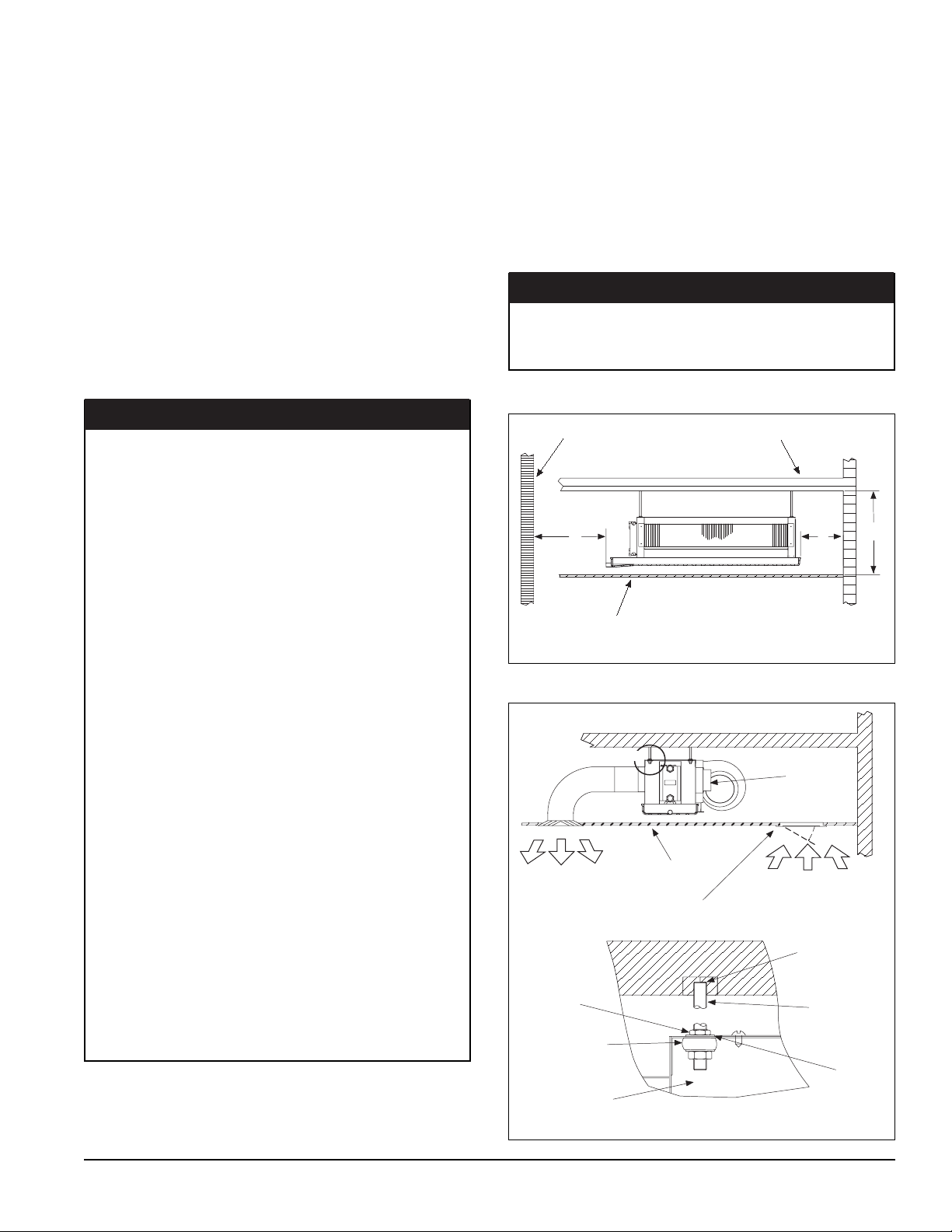
Installation
Discharge Air
Return Air
Ceiling
Ceiling Access Panel
with Air Return
Terminal
Block
A
Fan Coil
Unit
Flat
Washer
Hanging
Rod
Expansion
Screw
Nut
Detail A
Vibration
Isolator
(by others)
Receiving
All units leaving the McQuay plant are inspected for quality
prior to shipment.
Carefully inspect all shipments immediately upon delivery. Note
visible damage on the carrier’s freight bill and request that the
carrier send a representative to inspect the damage. This may
be completed by telephone or in person, but should always be
confirmed in writing.
The shipment should be unpacked in the presence of the agent
so that the extent of the damage or loss can be determined. The
carrier’s agent will make an inspection report and a copy will
be given to the consignee for forwarding to the carrier with a
formal claim.
Unit Installation
The unit is designed to be concealed in the ceiling. Installation
and maintenance should be performed by qualified personnel
who are familiar with local codes and regulations, and experienced with this type of equipment.
There are holes on the top of the unit for hanging the unit above
the ceiling. Please refer to Figure 1. , Figure 2., and Figure 3.
NOTE: Vibration isolaters provided by others.
NOTICE
Make sure the top of the unit is level after installation. The
drain pan is designed with a little gradient to facilitate
drainage. Do Not Level Drain Pan!
NOTICE
Before installation and running the unit, please check the
following:
1. There must be enough space for the unit installation
and maintenance. Please refer to the unit outline and
dimensions in Figure 1 for the minimum distance
between the unit and obstacles.
2. Mount with the lowest moving parts at least 8 feet above
the floor or grade level.
3. Ensure enough space for piping connection and
electrical wiring.
4. Leave a means for disconnection from the electrical
supply according to NEC or local codes.
5. Check whether the hanging rods can support the weight
of the unit.
6. The unit must be installed horizontally for proper
operation and condensate draining.
7. The external static pressure must be within the
allowable static pressure range.
8. The installing contractor must supply service valves and
insulation for water piping in accordance with local codes
and regulations.
Figure 1.
Figure 2.
Obstacle
B
Ceiling
Obstacle
A=8 in.
B= 16 in.
C=16 in.
A
C
9. To prevent strain on the wire connections, use either
conduit or approved strain relief device.
10. Confirm that the power has been switched OFF before
installing or servicing the unit.
IM 745 / Page 3 of 8 ©2003 McQuay International
Page 4

Figure 3.
Pipe Connection
Chilled Water Pipe Connection
Connect chilled water pipes to the unit. The water inlet is on the
A
bottom and water outlet is on top.
Return Air
Plenum
Ceiling
Discharge Air
Nut
Vibration
Isolator
(by others)
Fan Coil
Unit
Return Air
Detail A
Return Air Grille
with Filter
Expansion
Screw
Hanging
Rod
Flat
Washer
Air Duct Connection
Air ducts should be made of galvanized steel and
connected to the flange of the unit with a canvas connector.
Refer to the unit dimensions. Insert the duct into the flange and
fix with screws.
Duct connections must be installed in accordance with national
and local codes.
Wiring
Wiring connection must be completed according to the wiring
diagram on the unit.
The unit must be GROUNDED.
Installation of all field wiring must comply with NEC and
local codes.
WARNING
!
A means for disconnect from electrical supply shall be
provided according to NEC or local codes. Confirm that the
power has been switched OFF before installing or servicing
the unit.
Maintenance
General
A good general maintenance plan will avoid performance loss
and unexpected shut-down of the equipment.
A dirty filter reduces air flow as well as unit performance. Changing or cleaning the filter is very important. Check the filter
monthly and replace or clean as required.
Drain Pipe Connection - Per Local Codes
The drain pipe can be PVC or steel. Connect the drain pipe to
the unit. Pipe insulation is recommended to avoid condensation. The suggested slope of the drain pipe is at least 1/8" per
foot, but local code will prevail. Refer to Figure 4 for typical
piping installation.
NOTE: See suggested condensate (trap) drawing on page 6.
Figure 4.
Air Flow
Return Ball Valve
Control Valve
Actuator
Supply Gate Valve
Coils should be cleaned of dust, dirt and lint with compressed
air or water. They can be vacuumed or brushed with a soft brush.
CAUTION
!
Water coils exposed to freezing temperatures should be
drained or anti-freeze should be added to the water circuit
to avoid freezing.
Monthly intervals
1. Inspect and clean the condensate drain pan to help avoid
clogging of drainage by dirt, dust, etc. Inspect drainage
piping for proper condensate flow.
2. Check and clean the coil. Clean the coil with a low pressure
water jet or low pressure air.
3. Clean and tighten all the wiring connections.
IM 745 / Page 4 of 8 ©2003 McQuay International
Page 5

Dimensional Data – THC Horizontal Concealed, with Extended Drain Pan and Plenum Filter Box
Unit Size A B C D E F
Number
of Fans Size Qty
H02 32.05" 17.64" 19.17" 19.96" 18.46" 21.13" 1 181/8" x 8" x 1" 1
H03 38.74" 24.33" 25.87" 26.65" 25.15" 27.82" 1 247/8" x 8" x 1" 1
H04 43.86" 29.45" 30.98" 31.77" 30.20" 32.94" 2 297/8" x 8" x 1" 1
H06 51.73" 37.32" 38.86" 39.65" 38.07" 40.82" 2 187/8" x 8" x 1" 2
H08 61.57" 47.17" 48.70" 49.49" 47.91" 50.66" 3 233/4" x 8" x 1" 2
H10 65.51" 51.10" 52.64" 53.43" 51.85" 54.60" 3 253/4" x 8" x 1" 2
H12 75.75" 61.34" 62.87" 63.66" 62.09" 64.83" 4 30
All dimensions ± 0.10"
F
Filters
7
/8" x 8" x 1" 2
8.75"
2.32"
7.36"
1.5"
D
E
2"
A
TOP VIEW
B
C
FILTER
- R/A PLENUM
MOUNTING HOLES 3/8" x 5/8"
4 - MOUNTING
HOLES 3/8" x 5/8"
CONDENSATE
DRAIN
6.38"
9.75"
AIR
VENT
3/4" MPT
Plenum Back with Filter
1.02"
5.75"
9.75"
FRONT VIEW
1.40"
CONDENSATE
DRAIN 3/4" MPT
FILTER
RAIL
CHILLED WATER
CONNECTION 3/4" FPT
WATER RETURN
CONNECTION 3/4" FPT
1.25"
1.25"
4.53"
9.25"
23.25"
1.73"
12.75"
TERMINAL BLOCK
1.25"
1.25"
9.25"
5.82"
23.25"
TERMINAL BLOCK
2.75"
9.88"
3.46"
HOT WATER
CONNECTION
3/4" FPT
9.53"
WATER SUPPLY
CONNECTION 3/4" FPT
4-Pipe System
9.88"
4.72"
8.125"
9.53"
2-Pipe System
IM 745 / Page 5 of 8 ©2003 McQuay International
Page 6

Suggested Condensate Trapping
The condensate trap provides the water seal (water level in the
condensate trap) to prevent the flow of air from the condensate
drain line into the coil section during normal operation.
Suggested Condensate Trap
CONDENSATE
PAN
Improper trapping can lead to several problems. If the trap is
too tall, back pressure will prevent drainage, causing condensate backup. If the trap is too short the seal will be destroyed or
nonexistent, producing the same effect as a non-trapped
C
system.
The trap should be constructed of 7/8" clear plastic piping. The
condensate piping from the drain trap must be sloped to facilitate proper drainage. The clear plastic trap should be clamped
and removable for cleaning. It may be necessary to manually
fill the trap at system start-up, or to run the unit for sufficient
time to build a condensate seal. The condensate trap and condensate piping drainage should be free of any foreign debris.
Condensate Drain Trap Dimensions
ABC
1
/2" 3/4" 31/8"
1
Foreign debris can prevent proper operation resulting in condensate buildup.
Wiring Diagrams
For Models: THCH02, THCH03, THCH04, and THCH06
Wiring (115V/1P/60Hz)(208-230V/1P/60Hz)(265/277V/1P/60Hz) Wiring (220V/1P/50Hz)
7/8" I.D.
A
B
FAN SPEED
SWITCH
BLACK
POWER
WHITE
G/Y
SOURCE
NOTE:
MAIN SWITCH
M~: FAN MOTOR
G/Y: GREEN/YELLOW
LF: FAN SPEED LOW
L
M
H
FIELD WIRING
LF
MF
HF
SHF
N
G
ORANGE
BROWN
YELLOW
RED
L
BLUE
G/Y
For Models: THCH08, THCH10, THCH12
FAN SPEED
SWITCH
BLACK
POWER
WHITE
G/Y
SOURCE
NOTE:
M1,M2: FAN MOTOR
G/Y: GREEN/YELLOW
LF: FAN SPEED LOW
L
M
H
MAIN SWITCH
FIELD WIRING
LF
MF
HF
SHF
L
N
G
ORANGE
BROWN
YELLOW
RED
BLUE
G/Y
BLACK
M~
BLACK
G/Y
MF: FAN SPEED MEDIUM
HF: FAN SPEED HIGH
SHF: FAN SPEED SUPER HIGH
BLACK
M1
BLACK
G/Y
ORANGE
BROWN
YELLOW
RED
MF: FAN SPEED MEDIUM
HF: FAN SPEED HIGH
SHF: FAN SPEED SUPER HIGH
BLACK
M2
BLACK
G/Y
FAN SPEED
POWER
SOURCE
NOTE:
M~: FAN MOTOR
G/Y: GREEN/YELLOW
LF: FAN SPEED LOW
FAN SPEED
SWITCH
POWER
SOURCE
NOTE:
M1,M2: FAN MOTOR
G/Y: GREEN/YELLOW
LF: FAN SPEED LOW
SWITCH
L
M
H
BLACK
WHITE
MAIN SWITCH
FIELD WIRING
L
M
H
BLACK
WHITE
MAIN SWITCH
FIELD WIRING
LF
MF
HF
SHF
SHF
L
N
LF
MF
HF
L
N
ORANGE
BROWN
YELLOW
RED
BLUE
ORANGE
BROWN
YELLOW
RED
BLUE
G/Y
MF: FAN SPEED MEDIUM
HF: FAN SPEED HIGH
SHF: FAN SPEED SUPER HIGH
ORANGE
BROWN
YELLOW
G/Y
RED
MF: FAN SPEED MEDIUM
HF: FAN SPEED HIGH
SHF: FAN SPEED SUPER HIGH
BLACK
M~
BLACK
G/Y
BLACK
M1
BLACK
G/Y
BLACK
M2
BLACK
G/Y
IM 745 / Page 6 of 8 ©2003 McQuay International
Page 7

Control Wiring Schematic - Heating/Cooling 2-Pipe With Automatic Changeover
Legend
16
Wire No.
ORG
CLG
BLU
BLU
C/O
BLK
BLK
V
WHT
TCI
RED
HTG
RED
Control Wiring Schematic - Heating/Cooling 4-Pipe With Sequencing Thermostat
Legend
ORG
WHT
CLG
HTG
TCI
V
C/O
TCI
CLG
BLU
HTG
RED
BLK
BLK
CLG
V
HTG
V
WHT
WHT
WHT
CLG
HTG
TCI
V
C/O
Wire No.
16
Wire Color
WHT
Wire Connector
Wire Connector
Field Connector
Cooling
Heating
Thermostat
Val ve
Change over Switch
(Manual or Auto)
Wire Color
Wire Connector
Wire Connector
Field Connector
Cooling
Heating
Thermostat
Valve
Change over Switch
(Manual or Auto)
IM 745 / Page 7 of 8 ©2003 McQuay International
Page 8

This document contains the most current product information as of this printing. For the most up-to-date
product information, please go to www.mcquay.com.
®
4900 Technology Park Boulevard • Auburn, New York 13021-9030 • 800-432-1342 • www.mcquay.com IM 745-2 / (Rev 6-03) Pg 8 of 8
©2003 McQuay International
 Loading...