

Page 1
Installation Manual
Group: Chiller
Part Number: 331975501
Effective: October 2008
Supersedes: New
Templifier® Heat Recovery Water Heaters
TGZ 040A to TGZ 190A, Packaged Water Heater
600 to 3100 MBH
R134a
50/60 Hz
IM TGZ
Page 2
TABLE OF CONTENTS
Introduction .........................................2
General Description...............................
Nomenclature.........................................
2
2
Inspection ..............................................2
Installation............................................
Handling ................................................
3
3
Moving the Unit ....................................3
Location.................................................4
Vibration Isolators.................................5
Water Piping........................................7
General ..................................................7
Source Water Piping..............................8
Source/Hot Water Thermostat...............
Flow Switch...........................................
8
9
Glycol Solutions..................................10
Condenser Water Piping......................10
Heating and Cooling Units..................11
Water Pressure Drop............................11
TGZ Scroll...........................................12
Dimensional Data...........................16
Weights............................................24
Physical Data..................................25
TGZ Scroll.......................................25
Unit Components ...........................29
Wiring.............................................31
Electrical Data................................33
Start-Up and Shutdown.................41
Pre Start-up ......................................41
Start-up.............................................41
Extended Shutdown.........................42
Start-up after Extended Shutdown...42
General............................................42
Electrical Terminals.........................43
Operating Limits..............................43
Compressor Oil................................44
Sightglass and Moisture Indicator ...44
Troubleshooting Chart..................45
HAZARD IDENTIFICATION INFORMATION
!
DANGER
Dangers indicate a hazardous situation which will result in death or serious injury if not avoided.
!
WARNING
Warnings indicate potentially hazardous situations, which can result in property damage,
severe personal injury, or death if not avoided.
!
CAUTION
Cautions indicate potentially hazardous situations that can result in personal injury or equipment
damage if not avoided.
Manufactured in an ISO Certified facility
©2008 McQuay International. Illustrations and data cover the McQuay International product at the time of publication and we reserve the right to make
changes in design and construction at anytime without notice. ™® The following are trademarks or registered trademarks of their respective companies:
BACnet from ASHRAE;
license granted by Echelon Corporation; Modbus from Schneider Electric; MicroTech II and Open Choices from McQuay International
LONMARK, LonTalk, LONWORKS, and the LONMARK logo are managed, granted and used by LONMARK International under a
1 TGZ 040A through TGZ 190A IM TGZ
Page 3
Introduction
General Description
McQuay TGZ water heaters are scroll compressor refrigeration units that recover heat from warm fluid streams in
the evaporator and deliver hot water, at a useful temperature, from the condenser to a heating load. They are
designed for indoor installations only and are completely assembled, wired, charged and tested. Each unit consists
of four or six (depending on unit size) scroll compressors, brazed-plate evaporators on models 040 through 120
and shell-and-tube evaporators on models 150 to 190, shell-and-tube condenser/heater, and complete refrigerant
piping.
There are two refrigerant circuits, each with manual liquid line shutoff valves, charging valves, filter-driers, liquid
line solenoid valves, sightglass/moisture indicators, and thermal expansion valves.
®
The electrical control center includes a MicroTech II
dependable automatic operation.
Nomenclature
T G Z 100 A
Templifier
Global
control system and other components necessary for
Vintage
Scroll Compressor
Nominal
Evaporator Tons
Inspection
When the equipment is received, all items should be carefully checked against the bill of lading to provide a
complete shipment. All units must be carefully inspected for damage upon arrival. All shipping damage must be
reported to the carrier and a claim must be filed with the carrier. The unit serial plate should be checked before
unloading the unit to be sure that it agrees with the power supply available. Physical damage to unit after
acceptance is not the responsibility of McQuay.
Note: Unit shipping and operating weights are given in the Physical Data Tables beginning on page
24.
IM TGZ TGZ 040A through TGZ 190A 2
Page 4
Installation
TGZ040-190A / WGZ030-200C
Note: Installation and maintenance are to be performed only by qualified personnel who are
familiar with local codes and regulations, and experienced with this type of equipment.
!
WARNING
Avoid contact with sharp edges. Personal injury can result.
Handling
Every model TGZ water heater is shipped with a full refrigerant charge that is isolated in the condenser by the
manual condenser liquid valve and the compressor discharge service valve.
If the unit has been damaged, allowing the refrigerant to escape, there can be danger of suffocation in the
equipment area since the refrigerant will displace the air. Be sure to review Environmental Protection Agency
(EPA) requirements if damage has occurred. Avoid exposing an open flame to the refrigerant.
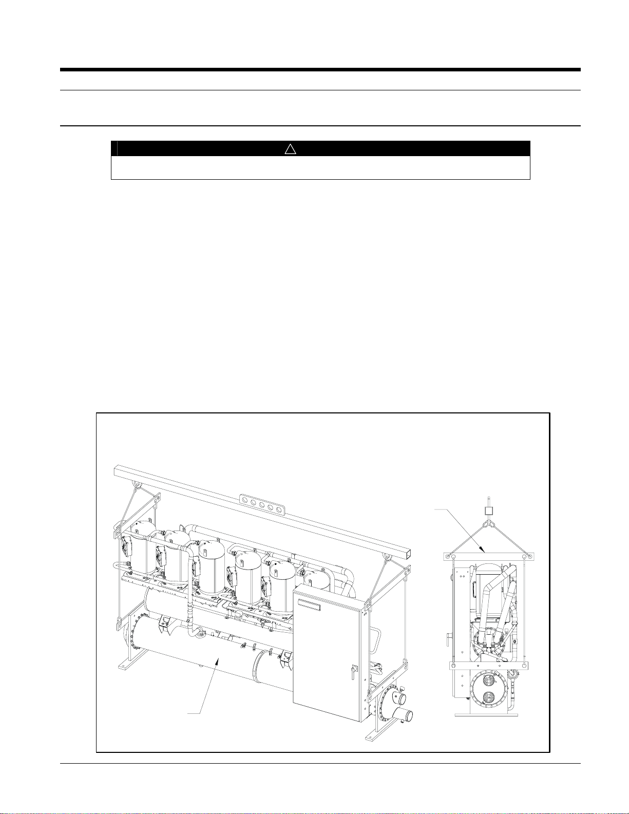
Moving the Unit
Moving the Unit The skid option is strongly recommended for ease of handling and to help prevent damage
if a crane is not available for rigging at site.
Figure 1, Lifting the Unit
RIGGING INSTRUCTIONS
SPREADER BARS MUST
BE USED FOR STABILITY
DURING LIFTING OF
ALL SIZE UNITS
WGZ150-200C
UNIT SHOWN
3 TGZ 040A through TGZ 190A IM TGZ
331926901 REV. 0A
Page 5

It is recommended that all moving and handling be performed with skids under the unit when possible and that the
skids not be removed until the unit is in the final location. When moving the unit, dollies or simple rollers can be
used under the skids. Never put the weight of the unit against the control box.
In moving, always apply pressure to the base on the skids only and not to the piping or shells. A long bar will help
move the unit easily. Avoid dropping the unit at the end of the roll.
If the unit must be hoisted, it is necessary to lift the unit by attaching cables or chains at the lifting holes located on
the disposable lifting bars. Spreader bars must be used to protect the control cabinet and other areas of the unit (see
Figure 1)
Do not attach slings to piping or equipment. Move unit in the upright horizontal position at all times. Set unit down
gently when lowering from the trucks or rollers.
Location
The unit is designed for indoor application and must be located in an area where the ambient temperature is above
40°F (4°C) minimum.
Because of the electronic control devices, the units should not be exposed to the weather. A plastic cover over the
control box is supplied as temporary protection during shipment. A reasonably level and sufficiently strong floor is
required for the unit. If necessary, additional structural members should be provided to transfer the weight of the unit
to the nearest beams.
Note: Unit shipping and operating weights are available in the Weights section beginning on page
24.
Space Requirements for Connections and Servicing
Allow a minimum of 4-foot clearance in front of the control panel. The source water and hot water piping enters and
leaves the unit from the right side when looking at the control panel. Left-hand condenser connections are an option.
A clearance of at least 3 feet (1219 mm), or more if codes require, should be provided beyond this piping and on all
other sides and ends of the unit for general servicing or for changing the compressors, if it ever becomes necessary.
Clearance should also be provided for cleaning or removal of condenser tubes, and evaporator tubes on models 150
to 190, on one end of the unit. The clearance for cleaning depends on the type of apparatus used, but can be as much
as the length of the largest condenser (12 feet, 3660 mm). Tube replacement requires the tube length plus one to two
feet of workspace. This space can often be provided through a doorway or other opening.
Placing the Unit
The small amount of vibration normally encountered with the water chiller makes this unit particularly desirable for
basement or ground floor installations where the unit can be mounted directly to the floor. The floor construction
should be such that the unit will not affect the building structure, or transmit noise and vibration into the structure.
IM TGZ TGZ 040A through TGZ 190A 4
Page 6
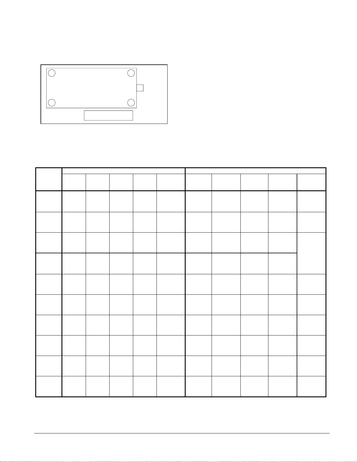
Vibration Isolators
It is recommended that isolators be used on all upper level installations or in areas where vibration transmission
is a consideration.
Figure 2, Isolator Locations
4
LB
RB
3
Water
Connections
Transfer the unit as indicated under “Moving the Unit.” In
all cases, set the unit in place and level with a spirit level.
When spring-type isolators are required, install springs
running under the main unit supports.
1
LF
FRF
2
The unit should be set initially on shims or blocks at the
listed spring free height. When all piping, wiring, flushing,
Control Panel
charging, etc., is completed, the springs are adjusted upward
to loosen the blocks or shims that are then removed.
A rubber anti-skid pad should be used under isolators if hold-down bolts are not used.
Installation of spring isolators requires flexible piping connections and at least three feet of flexible electrical
conduit to avoid straining the piping and transmitting vibration and noise
.
Table 1, Vibration Mounting Location and Kit Number
TGZ
MODEL
040A
050A
060A
080A
M1
(LEFT-
FRONT)
RP-3
Gray-WR
RP-3
Gray-WR
RP-3
Gray-WR
RP-4
Brown-WR
R-I-S MOUNTING LOCATION SPRING-FLEX MOUNTING LOCATION
M2
(RIGHTFRONT)
RP-3
Gray-WR
RP-3
Gray-WR
RP-3
Gray-WR
RP-4
Brown-WR
M3
(RIGHT-
REAR)
RP-3
Gray-WR
RP-3
Gray-WR
RP-3
Gray-WR
RP-4
Brown-WR
M4
(LEFTREAR)
RP-3
Gray-WR
RP-3
Gray-WR
RP-3
Gray-WR
RP-4
Brown-WR
KIT PART
NUMBER
332325701
332325701
332325701
332325702
M1
(LEFT-
FRONT)
CP1E-
ID-900
Dk. Green
CP1E-
ID-900
Dk. Green
CP1E-
ID-900
Dk. Green
CP2E-
ID-1350
Dk. Purple
M2
(RIGHTFRONT)
CP1EID-900
Dk. Green
CP1EID-900
Dk. Green
CP1EID-900
Dk. Green
CP2E-
ID-1350
Dk. Purple
M3
(RIGHT-
REAR)
CP1E-
ID-900
Dk. Green
CP1E-
ID-900
Dk. Green
CP1E-
ID-900
Dk. Green
CP2E-
ID-1350
Dk. Purple
M4
(LEFTREAR)
CP1E-
ID-900
Dk. Green
CP1E-
ID-900
Dk. Green
CP1E-
ID-900
Dk. Green
CP2E-
ID-1350
Dk. Purple
KIT PART
NUMBER
332320701
332320701
332320701
332320702
100A
110A
120A
150A
170A
190A
RP-4
Brown-WR
RP-4
Red-WR
RP-4
Red-WR
RP-4
Lime-WR
RP-4
Lime-WR
RP-4
Lime-WR
RP-4
Brown-WR
RP-4
Red-WR
RP-4
Red-WR
RP-4
Lime-WR
RP-4
Lime-WR
RP-4
Lime-WR
RP-4
Brown-WR
RP-4
Red-WR
RP-4
Red-WR
RP-4
Lime-WR
RP-4
Lime-WR
RP-4
Lime-WR
RP-4
Brown-WR
RP-4
Red-WR
RP-4
Red-WR
RP-4
Lime-WR
RP-4
Lime-WR
RP-4
Lime-WR
332325702
332325703
332325703
332325704
332325704
332325704
CP2E-
ID-1800
Dk. Green
CP2E-
ID-1800
Dk. Green
CP2E-
ID-1800
Dk. Green
CP2E-
ID-2400
Gray
CP2E-
ID-2400
Gray
CP2E-
ID-2400
Gray
CP2E-
ID-1800
Dk. Green
CP2E-
ID-1800
Dk. Green
CP2E-
ID-1800
Dk. Green
CP2E-
ID-2400
Gray
CP2E-
ID-2400
Gray
CP2E-
ID-2400
Gray
CP2E-
ID-1800
Dk. Green
CP2E-
ID-1800
Dk. Green
CP2E-
ID-1800
Dk. Green
CP2E-
ID-2400
Gray
CP2E-
ID-2400
Gray
CP2E-
ID-2400
Gray
CP2E-
ID-1800
Dk. Green
CP2E-
ID-1800
Dk. Green
CP2E-
ID-1800
Dk. Green
CP2E-
ID-2400
Gray
CP2E-
ID-2400
Gray
CP2E-
ID-2400
Gray
332320703
332320703
332703703
332320704
332320704
332320704
NOTE: For Spring-flex mountings, CP2E have two springs per isolator housing, CP1E have one spring per housing.
5 TGZ 040A through TGZ 190A IM TGZ
Page 7
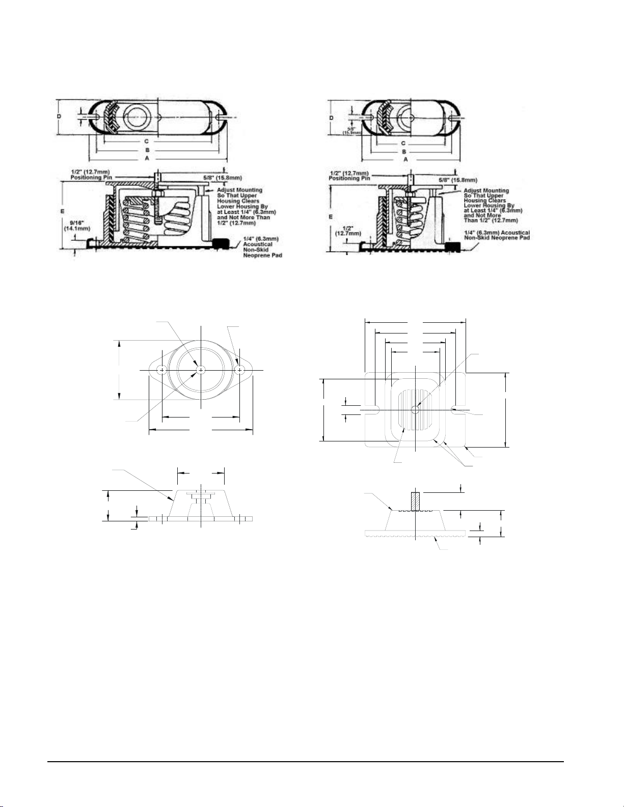
Figure 3, Isolator Dimensions
6
D
S
E
A
Spring Flex Mounting. CP-2 Spring Flex Mounting, CP-1
Rubber-in-Shear Mounting, RP-3
1/2-13 TAP
ø3.38
ø.5
2 HOL
Rubber-in-Shear, RP-4
6.25
5.00
3.75
3.00
R4
ø .500-13NC-2B
LOCA TING PIN TO
BE INSTALLED HERE
MOUNTING MOLDED IN
DURULENE. WEATHER
RESISTANT (WR)
1.75 (R)
.25
4.13
5.50
DRAWING NUMBER 3319880
ALL DIMENSION
2.50
ARE IN DECIMAL INCH
3.87
.56 TYP.
DURULENE
MATERIAL
NOTES:
MOUNT MATERIAL TO BE DURULENE RUBBER.1.
MOLDED STEEL AND ELASTOMER MOUNT FOR2.
OUTDOOR SERVICE CONDITIONS.
3. RP-4 MOUNT VERSION WITH STUD IN PLACE.
VM&C
RECESSED
GRIP RIBS
VM&C
R4
1.13 ± .25
APPROX.
RAISED GRIP RIBS
DRAWING NUMBER 3314814
LL DIMENSIONS ARE IN DECIMAL INCHES
R.28
TYP.
R.250 TYP.
R.750 TYP.
.38
4.63
1.63
IM TGZ TGZ 040A through TGZ 190A 6
Page 8

Water Piping
General
Due to the variety of piping practices, it is advisable to follow the recommendations of local authorities. They can
supply the installer with the proper building and safety codes required for a safe and proper installation.
Note: Since the Templifier evaporator and/or condenser may have to be valved off for cleaning or repair, it may
be essential that a bypass be piped around them so that source and hot water flow is not interrupted.
The piping should be designed with a minimum number of bends and changes in elevation to keep system cost
down and performance up. It should contain:
1. All piping should be installed and supported to prevent the unit connections from bearing any strain or
weight of the system piping.
2. Vibration eliminators to reduce vibration and noise transmission to the building.
3. Shutoff valves to isolate the unit from the piping system during unit servicing.
4. Manual or automatic air vent valves at the high points of the system. Drains should be placed at the
lowest points in the system.
5. Some means of maintaining adequate system water pressure (e.g., expansion tank or regulating valve).
6. Temperature and pressure indicators located within 3 feet (0.9 meters) of the inlet and outlet of the
vessels to aid in unit servicing.
7. A strainer or some means of removing foreign matter from the water before it enters the pump is
recommended. It should be placed far enough upstream to prevent cavitation at the pump inlet (consult
pump manufacturer for recommendations). The use of a strainer will prolong pump life and thus keep
system performance up.
8. A cleanable strainer must
condenser, 40-mesh on models TGZ 040 to 120 evaporators and 20-mesh on all other vessels. This will
aid in preventing foreign material from entering and decreasing the performance of the evaporator and
condenser.
9. Any water piping to the unit must be protected to prevent freezing. Consult the ASHRAE handbook for
standard industry practice.
10. If the unit is used in an existing piping system, the system should be thoroughly flushed prior to unit
installation. When job conditions permit, regular water analysis and chemical water treatment on the
evaporator and condenser is recommended commencing at equipment start-up.
11. The total quantity of water in the evaporator and condenser systems should be sufficient to prevent
frequent “on-off” cycling. For closed loop applications where the cooling load changes relatively
slowly, a minimum system volume of two to three minutes times the flow
recommended. For example, if the design chiller flow rate is 120 gpm, we recommend a system
volume of 240 to 360 gallons.
12. In the event glycol is added to the water system, as an afterthought for freeze protection, recognize that
the refrigerant suction pressure will be lower, cooling and heating performance lower, and water side
pressure drop will be greater. If the percentage of glycol is large, or if propylene is employed instead of
ethylene glycol, the added pressure drop and loss of performance could be substantial. Reset the
freezestat and low leaving water alarm temperatures. The freezestat is factory set to default at 36°F
(2.2°C). Reset the freezestat setting to approximately 4° to 5°F (2.3° to 2.8°C) below the leaving
chilled water setpoint temperature. See the section titled “Glycol Solutions” on page
information concerning glycol.
13. A preliminary leak check of the water piping should be made before filling the system.
A flow switch must be installed in the horizontal piping of the evaporator and condenser outlet
also be placed in the water lines just prior to the inlets of the evaporator and
rate (GPM) is
10 for additional
!
CAUTION
piping to prove water flow..
7 TGZ 040A through TGZ 190A IM TGZ
Page 9
Source Water Piping
r
The system water piping must be flushed thoroughly prior to making connections to the unit evaporator. Lay out
the water piping so the source water circulating pump discharges into the evaporator inlet.
!
CAUTION
A cleanable strainer must be placed in the water lines just prior to the inlets of the evaporator and
condenser, 40-mesh on models 040 to 120 evaporators and 20-mesh on all other vessels. Failure
to do so will cause damage to the equipment.
!
CAUTION
Templifier Models TGZ 040 through TGZ 120 must have clean source water from a closed and
treated loop going to the brazed-plate evaporator. For open water loop applications, an intermediate
heat exchanger between the source water and evaporator is required. Failure to provide a clean,
closed water loop can cause equipment failure and possible revocation of the unit warranty.
Templifier evaporator water can come from various sources and care must be exercised to avoid sources that can
cause corrosion, fouling, or accumulation of debris in the heat exchanger. Borderline cases will require a careful
and rigorously performed maintenance schedule.
Extensive, detailed information on the suitability of source water for brazed-plate exchangers can be found in an
Alfa Laval, June 2001 publication titled A Technical Reference for Plate Heat Exchangers in Refrigeration & Air-
conditioning Applications
Table 2, Evaporator Characteristics
TGZ UNIT SIZE EVAPORATOR MATERIALS STRAINER CLEANING
040A – 120A Brazed Plate Stainless Steel, Coppe
150A – 190A Shell-and-Tube Carbon Steel, Copper 20-Mesh Chemical
40-Mesh Chemical
Inlet and outlet connections are clearly marked on the unit and also appear on the dimension drawings, beginning
on page
16.
Drain connections should be provided at all low points in the system to permit complete drainage. Air vents
should be located at the high points in the system to purge out air. A vent connection, located on top of the
evaporator vessel, permits the purging of air out of the evaporator. Air purged from the water system prior to unit
start-up provides adequate flow through the vessel and prevents safety cutouts on the freeze protection. System
pressures can be maintained by using an expansion tank as a combination pressure relief and reducing valve.
Pressure gauges should be installed in the inlet and outlet water lines to the evaporator. Pressure drop through the
evaporator should be measured to calculate proper gpm (L/s) as specified in the Physical Data section tables,
beginning on page
25. Vibration eliminators are recommended in both the supply and return water lines.
Source water piping may have to be insulated (depending on its temperature) to reduce heat loss and prevent
condensation if cold water is used. If cooling tower water is used, insulation is not necessary. Complete unit and
system leak tests should be performed prior to insulating the water piping. Insulation with a vapor barrier is
recommended. If the vessel is insulated, the vent and drain connections must extend beyond the proposed
insulation thickness for accessibility. If the unit operates year-round, or if the system is not drained for the winter,
the chilled water piping exposed to outdoor ambient should be protected against freezing by wrapping the lines
with a heater cable.
Source/Hot Water Thermostat
The source water temperature sensor is factory installed in the leaving water connection on the evaporator. The
controlling hot water sensor is in the leaving condenser connection. A sensor is also located in the entering
IM TGZ TGZ 040A through TGZ 190A 8
Page 10
water connection in order to measure the condenser Delta-T. Care should be taken not to damage the sensor
V
cable or leadwires when working around the unit. It is also advisable to check the leadwire before running the
unit to be sure that it is firmly anchored and not rubbing on the frame or any other component.
If the sensor is ever removed from the well for servicing, care must be taken as not to wipe off the heat
conducting compound supplied in the well. The units can be switched from heating to cooling. In the cooling
mode they are controlled by a thermostat in the leaving evaporator connection, in the heating mode by the
condenser thermostat.
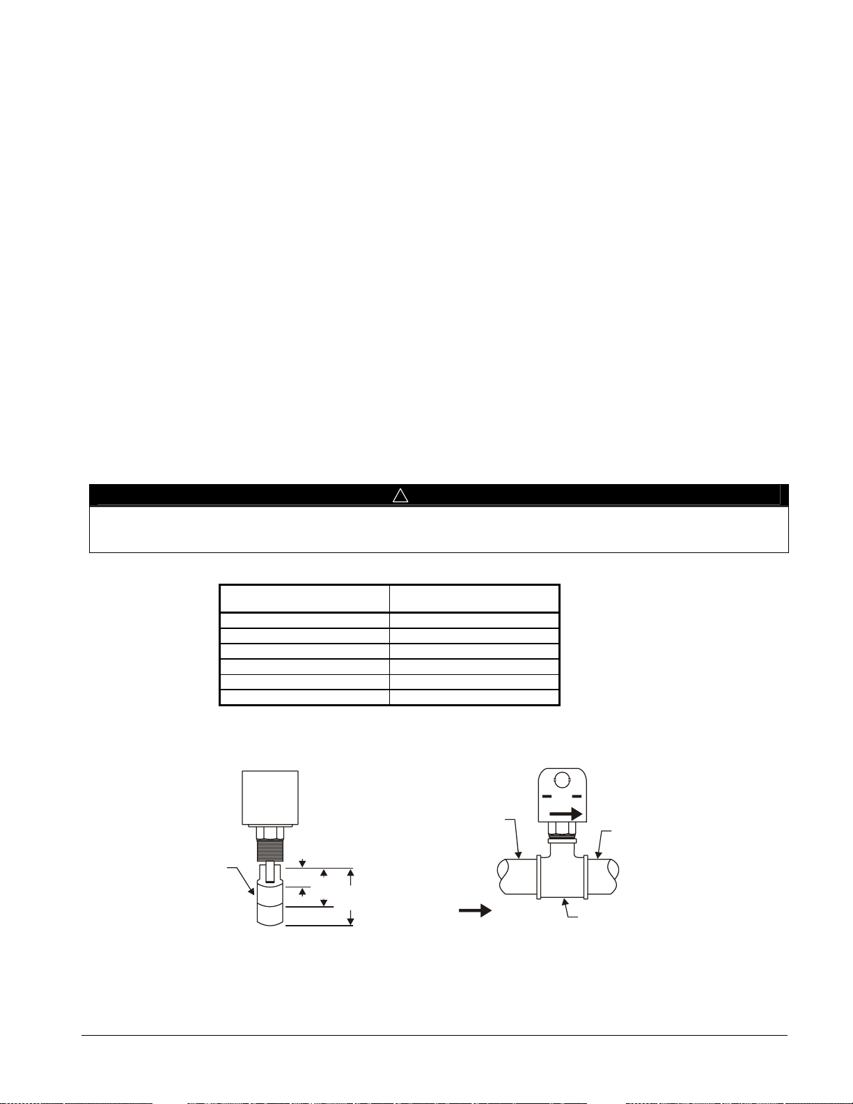
Flow Switch
A water flow switch must be mounted in the evaporator and condenser leaving water lines to prove adequate
water flow to the vessels before the unit can start. This will safeguard against slugging the compressors on
start-up. It also serves to shut down the unit in the event that water flow is interrupted to guard against
evaporator freeze-up.
A flow switch is available from McQuay under ordering number 01750330. It is a “paddle” type switch and
adaptable to any pipe size from 1” (25mm) to 6” (152mm) nominal. Certain minimum flow rates are required
to close the switch and are listed in
Diagram on page
32 for terminal locations. The normally open contacts of the flow switch should be wired
between these two terminals. There is also a set of normally closed contacts on the switch that could be used
for an indicator light or an alarm to indicate when a “no flow” condition exists.
1. Apply pipe sealing compound to only the threads of the switch and screw unit into D” x D” x 1 (25mm)
reducing tee (see
Figure 4). The flow arrow must be pointed in the correct direction.
2. Provide a straight length of pipe before and after the flow switch of at least five times the pipe diameter.
3. Trim flow switch paddle if needed to fit the pipe diameter. Make sure paddle does not hang up in pipe.
Table 3. Installation should be as shown on page 9. See the Field Wiring
!
CAUTION
Make sure the arrow on the side of the switch is pointed in the direction of flow. Install per manufacturer’s
instructions. Incorrect installation will cause improper operation and possible evaporator damage.
Table 3, Flow Switch Minimum Flow Rates
Nominal Pipe Size
Inches (mm)
2 (50.8) 18.8 (1.2)
2 1/2 (63.5) 24.3 (1.5)
3 (76.2) 30.0 (1.9)
4 (101.6) 39.7 (2.5)
5 (127.0) 58.7 (3.7)
6 (152.4) 79.2 (5.0)
Minimum Required Flow to
Activate Switch – GPM (l/s)
Figure 4, Flow Switch
iew From End of CoolerFlow Switch
Flow Switch
Paddle
1
(25)
(51)
Pipe Section
D” x 5D”
2
3
(76)
From
Evaporator
Flow
Direction
Flow
Straight Pipe
for at Least 5D”
Tee
D” x D” x 1”
9 TGZ 040A through TGZ 190A IM TGZ
Page 11
Glycol Solutions
T
The use of glycol in Templifier systems is rare but if used, the system glycol capacity, glycol solution flow rate in
gpm (lps), pressure drop through the cooler, and system pressure drop can be calculated using the following
formulas and table.
1. Capacity — Capacity is reduced from that with plain water. To find the reduced value multiply the unit’s
water system capacity by the capacity correction factor C, as shown in
capacity in the glycol system.
2. GPM —To determine evaporator gpm (or ΔT) knowing ΔT (or gpm) and capacity:
GPMGlycol
24
=
CapacityGlycolx
Δ
FromTablesGx
3. Pressure Drop — To determine glycol pressure drop through the cooler, enter the proper water pressure drop
curve, beginning on page
11, at the water flow. Multiply the water pressure drop found there by P to obtain
corrected glycol pressure drop.
4. To determine glycol system kW, multiply the water system kW by factor K.
Test coolant with a clean, accurate glycol solution hydrometer (similar to that found in service stations) to
determine the freezing point. Obtain percent glycol from the freezing point table below.
McQuay encourages a minimum glycol concentration of 25% be provided on all glycol applications. Glycol
concentrations below 25% have too little inhibitor content for long-term corrosion protection of ferrous metals.
Note: The effect of glycol in the condenser is negligible and there is no capacity derate. There is a
significant increase in pressure drop.
Table 4 and Table 5, to find the unit’s
Table 4, Ethylene Glycol
Glycol
20 18 -8 0.982 0.992 1.040 1.129
30 7 -14 0.972 0.986 1.074 1.181
40 -7 -22 0.961 0.976 1.121 1.263
50 -28 -33 0.946 0.966 1.178 1.308
Freezing Point Percent
°F °C
C (Capacity) K (Power) G (Flow)
P (Pressure
Drop)
Table 5, Propylene Glycol
Percent
Glycol
20 19 -7 0.975 0.985 1.028 1.147
30 9 -13 0.962 0.978 1.050 1.248
40 -5 -21 0.946 0.971 1.078 1.366
50 -27 -33 0.929 0.965 1.116 1.481
Freezing Point C (Capacity) K (Power) G (Flow)
°F °C
P (Pressure
Drop)
!
CAUTION
Do not use automotive grade antifreeze. Industrial grade glycols must be used. Automotive antifreeze contains
inhibitors which all cause plating on the copper within the unit evaporator. The type and handling of glycol used
must be consistent with local codes.
Condenser Water Piping
Arrange the condenser water so the water enters the bottom connection of the condenser. The condenser water
will discharge the condenser from the top connection. Failing to arrange the condenser water as stated above will
negatively affect the capacity and efficiency. Note that the condensers are shipped as either two-pass (10 to 20degree Delta-T) or four-pass (20 to 40-degree Delta-T). For 2-pass, the connections are on the vertical centerline
of the condenser. For 4-pass, they are off to one side.
Pressure gauges should be installed in the inlet and outlet water lines to the condenser. Pressure drop through the
condenser should be measured to determine gpm (L/s) from pressure drop curves on page
eliminators are recommended in both the supply and return water lines.
11. Vibration
IM TGZ TGZ 040A through TGZ 190A 10
Page 12
Templifier hot water systems usually have a supplementary heater located after (downstream) of the
Templifier condenser to either boost the hot water temperature or to function as a standby heater.
Care should be exercised to avoid overly warm water coming back to the Templifier from the system and
causing a relief valve discharge. This is true whether the unit is running or off. Maximum temperature is 165°F
Some jurisdictions require double heat exchange walls between refrigerant and potable water. Potable water
run directly through a condenser has only one heat exchange wall (the condenser tube) and these jurisdictions
may require an intermediate heat exchanger.
Heating and Cooling Units
Templifiers can be arranged and controlled to act as either a water chiller or a water heater. These
systems vary considerably in the specifics of the piping arrangement. Care must be exercised when
changeover occurs to avoid mixing water streams that could possibly contaminate a water system. For
example a unit can have chilled water in the evaporator and tower water in the condenser when in the
cooling mode. Changeover to heating could put tower water through the evaporator and hot water
(possibly potable water) through the condenser. This could introduce tower water into the chilled
water system and into the hot water system and should be avoided.
Water Pressure Drop
The vessel flow rates must fall between the minimum and maximum values shown on the appropriate
evaporator and condenser curves on pages
laminar flow that will reduce efficiency, cause erratic operation of the expansion valve and could cause low
temperature cutoffs. On the other hand, flow rates exceeding the maximum values shown can cause erosion on
the evaporator water connections and tubes.
Measure the water pressure drop through the vessels at field installed pressure taps. It is important not to
include valves or strainers in these readings.
The condenser flow rate will determine whether 2-pass or 4-pass condensers are used, according to the
following table:
12 to 14. Flow rates below the minimum values shown will result in
CONDENSER DELTA-T PASSES FLOW
10- to 20 Degrees F 2-Pass High Flow Rate
20 to 40 Degrees F 4-Pass Low Flow Rate
The entering water should be piped to the bottom connection of the condenser and out the top.
11 TGZ 040A through TGZ 190A IM TGZ
Page 13
TGZ Scroll
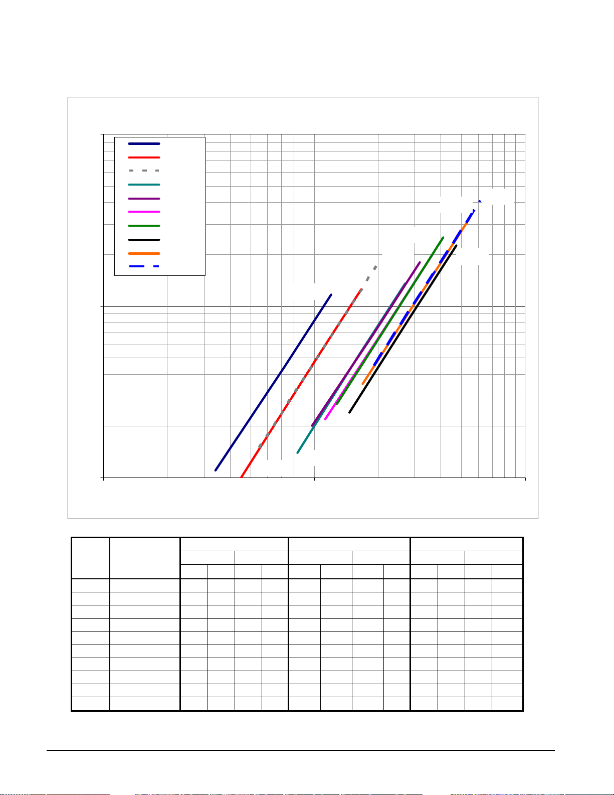
Figure 5, Evaporator Pressure Drop
TGZ Evaporator Wat er Pressur e Dr op
100
10
Dp (ft)
TGZ040
TGZ050
TGZ060
TGZ080
TGZ100
TGZ110
TGZ120
TGZ150
TGZ170
TGZ190
TGZ040
TGZ060
TGZ110
TGZ100
TGZ170
TGZ190
TGZ120
TGZ150
TGZ080
TGZ050
1
10 100 1000
Flow Rate (gpm)
TGZ UNIT
MODEL
040A
050A
060A
080A
100A
110A
120A
150A
170A
190A
Note: Nominal Flow Rate is gpm for 10 F Delta-T at unit operating conditions of evaporator at 75/65 F water temp and condenser at 110/30 F water temp.
EVAPORATOR
MODEL
AC250-70DQ 34 1.1 2.1 3.2 72 4.4 4.5 13.2 120 11.6 7.6 34.7
AC250-94DQ 45 1.0 2.8 3.1 100 4.7 6.3 14.0 167 12.5 10.5 37.2
AC250-94DQ 55 1.5 3.5 4.5 121 6.7 7.6 20.0 202 17.7 12.7 53.0
AC350-162DQ 83 1.4 5.2 4.3 162 5.1 10.2 15.2 270 13.5 17.0 40.2
AC350-162DQ 98 2.0 6.2 5.8 189 6.8 11.9 20.3 315 17.9 19.9 53.6
AC350-182DQ 113 2.2 7.1 6.4 218 7.5 13.8 22.4 363 19.8 22.9 59.1
AC350-182DQ 128 2.7 8.1 8.2 246 9.5 15.5 28.4 410 25.1 25.9 74.9
EV34191111/9 147 2.4 9.3 7.3 283 8.5 17.9 25.4 472 22.5 29.8 67.1
EV34191212/7 169 3.5 10.7 10.5 326 12.2 20.6 36.5 543 32.2 34.3 96.1
EV34191212/7 192 4.5 12.1 13.4 369 15.5 23.3 46.3 615 40.9 38.8 122.3
MINIMUM FLOW RATE NOMINAL FLOW RATE MAXIMUM FLOW RATE
INCH-POUND S.I. INCH-POUND S.I. INCH-POUND S.I.
gpm ft. L/S kpa gpm ft. lps kpa gpm ft. lps kpa
IM TGZ TGZ 040A through TGZ 190A 12
Page 14
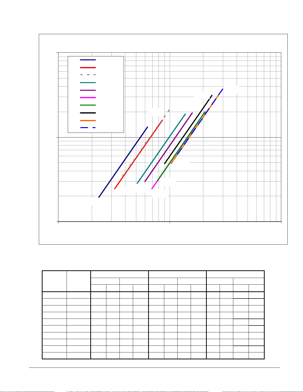
Figure 6, Standard Four-pass Condenser Pressure Drop
TGZ 4-Pa ss Conde nse r Wa t er Pressur e Dr op
100
TGZ040
TGZ050
TGZ060
TGZ080
TGZ100
TGZ110
TGZ120
TGZ150
TGZ060
TGZ170
TGZ190
10
Dp (ft)
TGZ170
TGZ150
TGZ100
TGZ190
TGZ120
TGZ050
TGZ040
TGZ080
TGZ110
1
10 100 1000
Flow Rate (gpm)
UNIT
MODEL
TGZ040
TGZ050
TGZ060
TGZ080
TGZ100
TGZ110
TGZ120
TGZ150
TGZ170
TGZ190
COND.
MODEL
C1010-62 23 1.93 1.45 5.77 47 7.5 3.0 22.4 63 13.1 4.0 39.1
C1010-62 32 2.44 2.02 7.29 64 9.1 4.0 27.2 86 16.0 5.4 47.7
C1010-76 38 3.40 2.40 10.16 77 13.0 4.9 38.9 103 22.6 6.5 67.5
C1410-112 51 2.84 3.22 8.49 103 10.8 6.5 32.3 138 18.8 8.7 56.3
C1410-128 60 3.00 3.79 8.97 120 11.2 7.6 33.5 160 19.3 10.1 57.8
C1610-164 69 2.44 4.35 7.29 138 9.1 8.7 27.2 184 15.7 11.6 47.0
C1610-164 78 3.08 4.92 9.21 156 11.5 9.8 34.4 208 19.9 13.1 59.4
C1612-164 90 4.85 5.68 14.50 180 18.1 11.4 54.1 240 31.3 15.1 93.4
C1612-184 103 4.89 6.50 14.60 207 18.4 13.1 55.0 276 31.8 17.4 95.0
C1612-184 117 6.24 7.38 18.66 234 23.3 14.8 69.6 312 40.2 19.7 120.3
MINIMUM FLOW RATE NOMINAL FLOW RATE MAXIMUM FLOW RATE
INCH-POUND S.I. INCH-POUND S.I. INCH-POUND S.I.
gpm ft L/S kpa gpm ft L/S kpa gpm ft L/S kpa
13 TGZ 040A through TGZ 190A IM TGZ
Page 15
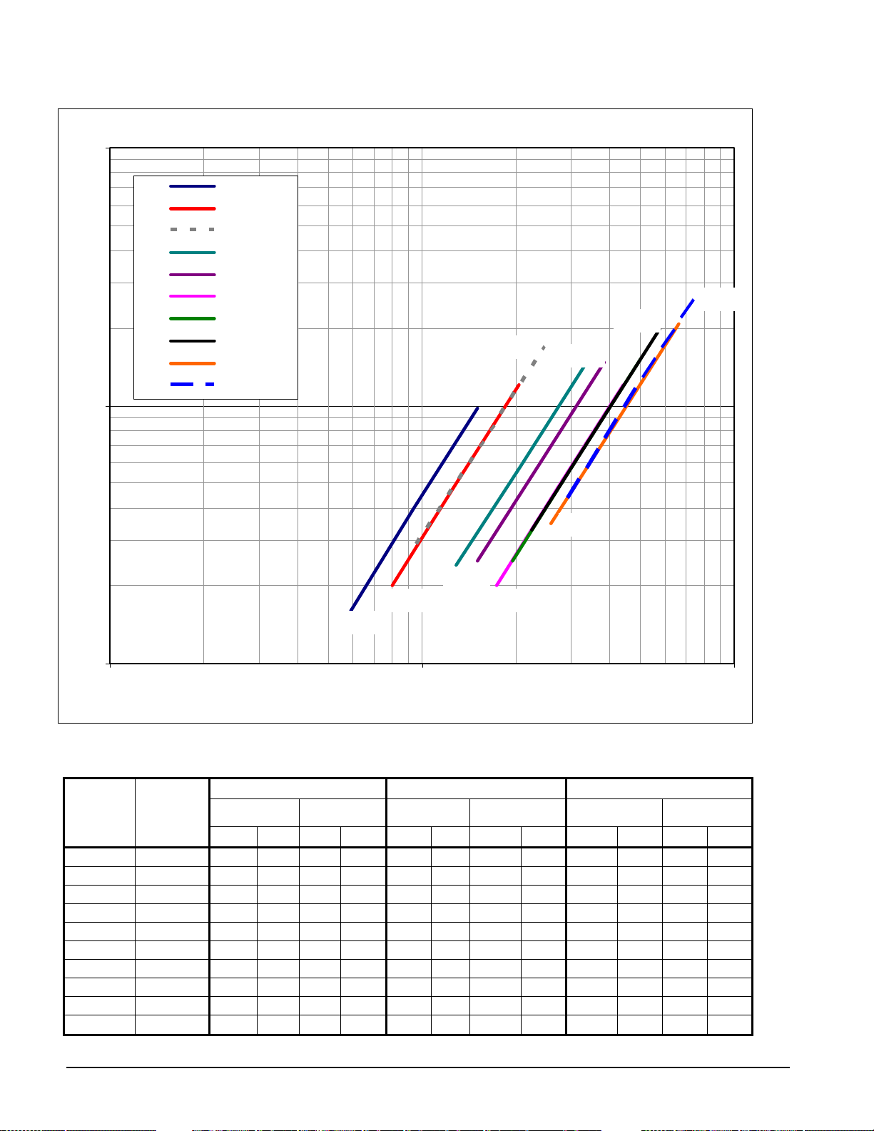
Figure 7, Optional Two-pass Condenser
TGZ 2- Pass Condenser Water Pressur e Drop
100
TGZ040
TGZ050
TGZ060
TGZ080
TGZ100
TGZ110
TGZ120
TGZ150
TGZ170
TGZ190
10
Dp (ft)
TGZ060
TGZ190
TGZ150
TGZ100
TGZ170
TGZ080
TGZ050
TGZ040
TGZ120
TGZ110
1
10 100 1000
Flow Rate (gpm)
MINIMUM FLOW RATE NOMINAL FLOW RATE MAXIMUM FLOW RATE
TGZ UNIT
MODEL
TGZ040
TGZ050
TGZ060
TGZ080
TGZ100
TGZ110
TGZ120
TGZ150
TGZ170
TGZ190
COND.
MODEL.
C1010-62 59 1.6 3.7 4.9 94 4.0 5.9 12.0 150 9.8 9.5 29.3
C1010-62 80 2.0 5.0 6.0 128 4.9 8.1 14.6 205 12.0 12.9 35.8
C1010-76 96 2.9 6.1 8.5 154 7.0 9.7 20.9 246 17.0 15.5 51.0
C1410-112 129 2.4 8.1 7.1 206 5.8 13.0 17.3 330 14.2 20.8 42.3
C1410-128 150 2.5 9.5 7.3 240 6.0 15.1 17.9 384 14.7 24.2 43.8
C1610-164 173 2.0 10.9 6.0 276 4.9 17.4 14.6 442 12.0 27.9 35.8
C1610-164 195 2.5 12.3 7.6 312 6.2 19.7 18.5 499 15.1 31.5 45.3
C1612-164 225 3.3 14.2 9.9 360 8.1 22.7 24.2 576 19.8 36.3 59.1
C1612-184 259 3.5 16.3 10.4 414 8.5 26.1 25.4 662 20.8 41.8 62.1
C1612-184 293 4.4 18.5 13.2 468 10.8 29.5 32.3 749 26.4 47.2 78.8
INCH-POUND S.I.
gpm ft L/S kpa gpm ft L/S kpa gpm ft lps kpa
INCH-
POUND
S.I. INCH-POUND S.I.
IM TGZ TGZ 040A through TGZ 190A 14
Page 16

Relief Valve Piping
The current ANSI/ASHRAE Standard 15 specifies that pressure relief valves on vessels containing Group 1
refrigerant (R-134a) “shall discharge to the atmosphere at a location not less than 15 feet (4.6 meters) above the
adjoining ground level and not less than 20 feet (6.1 meters) from any window, ventilation opening or exit in any
building.” The piping must be provided with a rain cap at the outside terminating point and a drain at the low point
on the vent piping to prevent water buildup on the atmospheric side of the relief valve. In addition, a flexible pipe
section should be installed in the line to eliminate any piping stress on the relief valve(s).
The size of the discharge pipe from the pressure relief valve shall not be less than the size of the pressure relief
outlet. When two or more vessels are piped together, the common header and piping to the atmosphere shall not be
less than the sum of the area of the relief valve outlets connected to the header. Fittings should be provided to permit
vent piping to be easily disconnected for inspection or replacement of the relief valve.
NOTE: Provide adequate fittings in piping to permit repair or replacement of relief valve.
Figure 8, Relief Valve Piping
15 TGZ 040A through TGZ 190A IM TGZ
Page 17

Dimensional Data
Figure 9, Dimensions, TGZ 040A - 060A, Standard 4-pass Condenser
4 PASS CONDENSER
L4 / M4
CONTROL BOX
"A"
L3 / M3
WATER
CONNECTIONS
VENT
DRAIN
3.8
REF.
98
L1 / M1
MICROTECH II USER INTERFACE
CIRCUIT 1CIRCUIT 2
RELIEF VALVES
121.1
3075
138.0
3506
32.9
837
30.2
768
" Y "
" X "
L2 / M2
13.1
333
3.9
100
OUTLET
CONDENSER
INLET
4 PASS CONDENSER
3"/(76) NOM. WATER
CONNECTIONS
CONTROL
CONNECTION
.88 KNOCKOUTS
ON OPPOSITE SIDE
POWER
CONNECTIONS
REMOVABLE
DISC. HANDLE
" Y "
.88 KNOCKOUTS
63.2
1605
23.5
597
2.0
51
20.0
508
12.2
309
INLET
OUTLET
29.0
737
32.0
813
40.0
1016
10.9
277
" Z "
15.7
398
.875 DIA MOUNTING HOLES (4)
EVAPORATOR
REMOVE BRKT.
FOR SHIPPING
ONLY
8.6
218
52.4
1331
27.7
703
13.4
340
ALL DIMENSIONS ARE IN DECIMAL INCHES
DRAWING NUMBER
SCALE
NONE
3324297
IM TGZ TGZ 040A through TGZ 190A 16
Page 18

Figure 10, Dimensions, TGZ 040A – 060A, Optional 2-Pass Condenser
A
OPTIONAL 2 PASS CONDENSER
Table 6, 2-Pass and 4-pass Dimensions
CONDENSER WATER
CONNECTION IN(MM)
VICTAULIC
(4 PASS)
TGZ
MODEL
NUMBER
TGZ 040
TGZ 050
TGZ 060
CHILLER WATER
CONNECTION IN(MM)
VICTAULIC
SIZE A SIZE SIZE X Y Z
3 (76) 13.1 (333) 3 (76) 4 (102) 58.3 23.5 14.4
3 (76) 10.5 (267) 3 (76) 4 (102) 57.4 24.0 14.4
3 (76) 10.5 (267) 3 (76) 4 (102) 57.5 23.9 14.4
NOTE: Lifting and corner weights are in the “Weights” section on page 16.
4.1
103
13.7
349
CONDENSER WATER
CONNECTION IN(MM)
VICTAULIC
(2 PASS)
4" / (102) NOMINAL
WATER CONNECTIONS
LL DIMENSIONS ARE IN DECIMAL INCHES
DRAWING NUMBER
SCALE
NONE
CENTER OF GRAVITY
3324297
5.9
150
8.0
204
13.3
338
17 TGZ 040A through TGZ 190A IM TGZ
Page 19

Figure 11, Dimensions, TGZ 080A – 100A, Standard 4-Pass Condenser
D
S
4 PASS CONDENSER
CONTROL BOX
L1 / M1 L2 / M2
MICROTECH II USER INTERFACE
CIRCUIT 2 CIRCUIT 1
L3 / M3L4 / M4
CONDENSER
INLET/OUTLET
EVAP WATER
CONNECTION
"A"
VENT
RAIN
3.9
100
OUTLET
CONDENSER
INLET
RELIEF VALVES
" X "
"T"
CONTROL
CONNECTION
.88 KNOCKOUTS
ON OPPOSITE SIDE
REMOVABLE
DISC. HANDLE
POWER
CONNECTIONS
" Y "
23.5
597
2.0
51
"H"
20.0
508
14.5
369
121.1
3075
"L"
40.2
1021
"W"
32.5
825
INLET
OUTLET
10.6
269
EVAPORATOR
REMOVE BRKT.
FOR SHIPPING
ONLY
32.8
834
16.0
407
57.6
1462
14.4
367
4 PASS CONDENSER
4"/(102) NOM. WATER
CONNECTIONS
.88 KNOCKOUTS
16.0
406
" Z "
.875 DIA MOUNTING HOLES (4)
29.0
737
32.0
813
40.0
1016
10.0
255
ALL DIMENSIONS ARE IN DECIMAL INCHES
DRAWING NUMBER
SCALE
NONE
3324298
IM TGZ TGZ 040A through TGZ 190A 18
Page 20

Figure 12, Dimensions, TGZ 080A - 100A, Optional 2-Pass Condenser
A
OPTIONAL 2 PASS CONDENSER
TGZ
MODEL
TGZ 080
TGZ 100
NOTE: Lifting and corner weights are in the “Weights” section on page 16.
Table 7, 2-Pass and 4-Pass Dimensions
CHILLER WATER
CONNECTION
IN(MM) VICTAULIC
SIZE A SIZE (NOM) SIZE (NOM)
3
(76)
3
(76)
1.7
(43)
1.7
(43)
CONDENSER WATER
CONNECTION IN(MM)
VICTAULIC (4 PASS)
4
(102)
4
(102)
CONDENSER WATER
CONNECTION IN(MM)
VICTAULIC (2 PASS)
4
(102)
4
(102)
18.2
463
T
13.6
(345)
14.4
(366)
4"/ (102) NOMINAL
WATER CONNECTIONS
4.0
102
LL DIMENSIONS ARE IN DECIMAL INCHES
DRAWING NUMBER
NONE
SCALE
CENTER OF GRAVITY
X Y Z
63.2 30.1 15.1
65.6 31.3 15.4
3324298
7.9
200
10.0
253
13.0
330
19 TGZ 040A through TGZ 190A IM TGZ
Page 21

Figure 13, Dimensions, TGZ 110 – 120, Standard 4-Pass Condenser
4 PASS CONDENSER
CONTROL BOX
L1 / M1 L2 / M2
MICROTECH II USER INTERFACE
CIRCUIT 2 CIRCUIT 1
L3 / M3L4 / M4
CONNECTIONS
"A"
CONDENSER
INLET/OUTLET
EVAP WATER
VENT
DRAIN
4.0
102
OUTLET
CONDENSER
INLET
RELIEF VALVES
3324298
14.2
361
" X "
"T"
CONTROL
CONNECTION
.88 KNOCKOUTS
ON OPPOSITE SIDE
REMOVABLE
DISC. HANDLE
POWER
CONNECTIONS
.88 KNOCKOUTS
" Y "
23.5
597
2.0
51
"H"
20.0
508
16.0
407
121.1
3075
148.6
3774
41.2
1046
"W"
34.5
876
INLET
OUTLET
29.0
32.0
10.3
261
737
813
40.0
1016
" Z "
15.7
400
.875 DIA MOUNTING HOLES (4)
9.9
251
EVAPORATOR
REMOVE BRKT.
FOR SHIPPING
ONLY
18.0
456
59.1
1500
34.3
872
ALL DIMENSIONS ARE IN DE CIMAL INCHES
SCALE
NONE
DRAWING NUMBER
4 PASS CONDENSER
4"/(102) NOM. WATER
CONNECTION
IM TGZ TGZ 040A through TGZ 190A 20
Page 22

Figure 14, Dimensions, Optional 2-Pass Condenser
OPTIONAL 2 PASS CONDENSER
TGZ
MODEL
TGZ 110
TGZ 120
5" / (127) NOMINAL
WATER CONNECTIONS
4.0
102
18.2
462
ALL DIMENSIONS ARE IN DECIMAL INCHES
SCALE
NONE
DRAWING NUMBER
13.3
3324298
NOTE: Lifting and corner weights are in the “Weights” section on page 16.
Table 8, 2-Pass and 4-pass Dimensions
CHILLER
WATER
CONNECTION
IN (MM)
VICTAULIC
SIZE A SIZE SIZE
3
(76)
3
(76)
0.5
(13)
0.5
(13)
CONDENSER
WATER
CONNECTION IN
(MM) VICTAULIC
(4 PASS)
4
(102)
4
(102)
CONDENSER
WATER
CONNECTION
IN(MM) VICTAULIC
(2 PASS)
5
(127)
5
(127)
T
13.3
(338)
13.3
(338)
CENTER OF
GRAVITY
X Y Z
64.3 30.6 15.0
64.0 30.1 15.0
8.7
221
9.6
243
337
21 TGZ 040A through TGZ 190A IM TGZ
Page 23

Figure 15, Dimensions, TGZ 150A – 190A, Standard 4-Pass Condenser
23
2
.5
596
EVAPORATOR
OUTLET
77.
1961
EVAPORATOR
INLET
1.3
34
4 PASS CONDENSER
L3 / M3L4 / M4
CONDENSER
INLET / OUTLET
VENT
DRAIN
L1 / M1
10.9
276
CIRCUIT 2
VENT
DRAIN
" Y "
CIRCUIT 1
145.1
3685
170.2
4322
36.5
927
T.B.D .
33.8
41.2
1046
859
RELIEF VALVES
" X "
CONTROL BOX
L2 / M2
MICROTECH II USER INTERFACE
4.0
102
CONDENSER
14.2
361
OUTLET
INLET
4 PASS CONDENSER
4" / (102) NOM. WATER
CONNECTIONS
CONTROL
CONNECTION
.88 KNOCKOUTS
ON OPPOSITE SIDE
REMOVABLE
DISC HANDLE
POWER
CONNECTIONS
77.7
1973
.88 KNOCKOUT
2.0
51
17.0
432
15.5
394
23.5
597
5.0
127
" Z "
.875 DIA MOUNTING HOLES (4)
29.0
737
32.0
813
40.0
1016
10.3
261
REMOVE BRKT.
FOR SHIPPING
ONLY
36.9
938
EVAP
INLET/
OUTLET
18.0
456
9.9
251
ALL DIMENSIONS ARE IN DECIMAL INCHES
DRAWING NUMBER
SCALE
NONE
3324299
IM TGZ TGZ 040A through TGZ 190A 22
Page 24

Figure 16, Dimensions, TGZ 150A - 190A, Optional 2-Pass Condenser
OPTIONAL 2 PASS CONDENSER
TGZ
MODEL
TGZ 150
TGZ 170
TGZ 190
5" / (127) NOMINAL
WATER CONNECTIONS
4.0
102
18.2
462
ALL DIMENSIONS ARE IN DECIMAL INCHES
DRAWING NUMBER
SCALE
NONE
NOTE: Lifting and corner weights are in the “Weights” section on page
Table 9, 2-Pass and 4-pass Dimensions
CHILLER WATER
CONNECTION IN(MM)
VICTAULIC
SIZE SIZE SIZE X Y Z
8 (203) 4 (102) 5 (127) 78.5 36.0 15.1
8 (203) 4 (102) 5 (127) 78.4 37.3 15.1
8 (203) 4 (102) 5 (127) 78.5 38.9 15.0
CONDENSER WATER
CONNECTION IN(MM)
VICTAULIC (4 PASS)
CONDENSER WATER
CONNECTION IN(MM)
VICTAULIC (2 PASS)
CENTER OF
GRAVITY
3324299
16.
8.7
221
9.6
243
13.3
337
23 TGZ 040A through TGZ 190A IM TGZ
Page 25

Weights
NOTE: Refer to the unit dimension drawing for lifting and mounting point’s physical location.
Table 10, TGZ Lifting, Mounting, and Total Weights (Inch-Lbs Units)
MODEL
TGZ040A
TGZ050A
TGZ060A
TGZ080A
TGZ100A
TGZ110A
TGZ120A
TGZ150A
TGZ170A
TGZ190A
LIFTING WEIGHT FOR EACH
L1 L2 L3 L4 M1 M2 M3 M4
592 638 625 580 633 682 668 620 2434 2604
590 653 641 580 633 701 688 622 2464 2644
597 660 650 588 646 714 703 636 2496 2699
1034 947 1021 1115 1111 1017 1097 1198 4116 4422
1126 952 1072 1268 1211 1023 1152 1363 4418 4749
1271 1123 1207 1366 1375 1215 1305 1478 4967 5373
1257 1122 1195 1339 1361 1214 1294 1450 4913 5319
1823 1546 1675 1975 2046 1735 1880 2216 7019 7877
1846 1570 1694 1991 2077 1767 1906 2241 7101 7991
1848 1566 1682 1986 2081 1763 1894 2235 7082 7972
POINT (LBS)
TGZ Lifting, Mounting, and Total Weights (SI Units)
MODEL
TGZ040A
TGZ050A
TGZ060A
TGZ080A
TGZ100A
TGZ110A
TGZ120A
TGZ150A
TGZ170A
TGZ190A
LIFTING WEIGHT FOR EACH
L1 L2 L3 L4 M1 M2 M3 M4
269 289 283 263 287 309 303 281 1104 1181
268 296 291 263 287 318 312 282 1118 1199
271 299 295 267 293 324 319 288 1132 1224
469 430 463 506 504 461 498 543 1867 2006
511 432 486 575 549 464 523 618 2004 2154
577 509 547 620 624 551 592 670 2253 2437
570 509 542 607 617 551 587 658 2229 2413
827 701 760 896 928 787 853 1005 3184 3573
837 712 768 903 942 802 865 1017 3221 3625
838 710 763 901 944 800 859 1014 3212 3616
POINT (KG)
MOUNTING LOADS FOR EACH
POINT (LBS)
MOUNTING LOADS FOR EACH
POINT (KG)
SHIPPING
SHIPPING
WEIGHT
(LBS)
WEIGHT
(KG)
OPERATING
WEIGHT
(LBS)
OPERATING
WEIGHT
(KG)
Figure 17, Lifting and Mounting Points Location
4
LB
1
LF
Control Panel
RB
FRF
3
Water
Connections
2
IM TGZ TGZ 040A through TGZ 190A 24
Page 26

Physical Data
TGZ Scroll
Table 11, TGZ040A - 060A
TGZ Unit Model TGZ 040A TGZ 050A TGZ 060A
No. Of Circuits 2 2 2
COMPRESSORS
Nominal Horsepower 10 10 13 13 15 15
Number per Circuit 2 2 2 2 2 2
Unloading Steps, % 25 / 50 / 75 100 25 / 50 / 75 100 25 / 50 / 75 100
Oil Charge, per compr. oz (l) 110 (3.3) 110 (3.3) 110 (3.3)
CONDENSER
Number 1 1 1
No. Refrigerant Circuits 2 2 2
Diameter, in. (mm) 10.75 (273) 10.75 (273) 10.75 (273)
Tube Length, in (mm) 122 (3099) 122 (3099) 122 (3099)
Design W.P.,psig (kPa):
Refrigerant Side 500 (3447) 500 (3447) 500 (3447)
Water Side 232 (1599) 232 (1599) 232 (1599)
Relief Valve Setting, psig (kPa) 500 (3447) 500 (3447) 500 (3447)
No. Of Water Passes - Standard 4 4 4
No. Of Water Passes - Optional 2 2 2
Water Volume, gallons (l) 13.6 (51.5) 13.6 (51.5) 16.3 (61.8)
Pump-Down Capacity lb., (kg) 121.7(55.2) 121.7(55.2) 121.7(55.2) 121.7(55.2) 107.3(48.7) 107.3(48.7)
Connections:
Water In & Out, in., (mm) (4 Pass) 3 (76) 3 (76) 3 (76)
Water In & Out, in., (mm) (2 Pass) 4 (102) 4 (102) 4 (102)
Relief Valve, Flare in., (mm) 5/8 (15.9) 5/8 (15.9) 5/8 (15.9)
Purge Valve, Flare in., (mm) 5/8 (15.9) 5/8 (15.9) 5/8 (15.9)
Vent & Drain, in (mm) FPT 1/2 (12.7) 1/2 (12.7) 1/2 (12.7)
Liquid Subcooling Integral Integral Integral
EVAPORATOR, BRAZED-PLATE
Number 1 1 1
No. Refrigerant Circuits 2 2 2
Water Volume, gallons (l) 3.7 (14.0) 5.0 (18.9) 5.0 (18.9)
Refrigerant Side D.W.P., psig, (kPa) 450 (3102) 450 (3102) 450 (3102)
Relief Valve Setting, psig (kPa) 450 (3102) 450 (3102) 450 (3102)
Water Side D.W.P., psig, (kPa) 450 (3102) 450 (3102) 450 (3102)
Water Connections:
In & Out, in. (mm) victaulic 3 (76) 3 (76) 3 (76)
Drain & Vent Field Supplied Field Supplied Field Supplied
UNIT DIMENSIONS
Length, in. (mm) 139 (3530) 139 (3530) 139 (3530)
Width, in. (mm) 33 (838) 33 (838) 33 (838)
Height, in. (mm) 63.2 (1605) 63.2 (1605) 63.2 (1605)
UNIT WEIGHTS
Operating WT., lb., (kg) 2604 (1181) 2644 (1199) 2699 (1224)
Shipping WT., lb. (kg) 2434 (1104) 2464 (1117) 2496 (1132)
R-134a Ref. Charge, lb. (kg) 45 (20.4) 45 (20.4) 45 (20.4) 45 (20.4) 50 (22.7) 50 (22.7)
25 TGZ 040A through TGZ 190A IM TGZ
Page 27

Table 12, TGZ 080A – 100A
TGZ Unit Model TGZ 080A TGZ 100A
No. Of Circuits 2 2
COMPRESSORS
Nominal Horsepower 20 20 25 25
Number per Circuit 2 2 2 2
Staging Steps, % 25 / 50 / 75 100 25 / 50 / 75 100
Oil Charge, per compressor. oz (l) 158 (4.7) 200 (5.9)
CONDENSER
Number 1 1
No. Refrigerant Circuits 2 2
Diameter, in. (mm) 14 (356) 14 (356)
Tube Length, in (mm) 122 (3099) 122 (3099)
Design W.P.,psig (kPa):
Refrigerant Side 500 (3447) 500 (3447)
Water Side 232 (1599) 232 (1599)
Relief Valve Setting, psig (kPa) 500 (3447) 500 (3447)
No. Of Water Passes - Standard 4 4
No. Of Water Passes - Optional 2 2
Water Volume, gallons (1) 27.5 (104) 27.5 (104)
Pump-Down Capacity lb., (kg) 186(84.2) 186(84.2) 186(84.2) 186(84.2)
Connections:
Water In & Out, in., (mm) (4 Pass) 4 (102) 4 (102)
Water In & Out, in., (mm) (2 Pass) 4 (102) 4 (102)
Relief Valve, Flare in., (mm) 5/8 (15.9) 5/8 (15.9)
Purge Valve, Flare in., (mm) 5/8 (15.9) 5/8 (15.9)
Vent & Drain, in (mm) FPT 1/2 (12.7) 1/2 (12.7)
Liquid Subcooling Intergral Intergral
EVAPORATOR, BRAZED PLATE
Number 1 1
No. Refrigerant Circuits 2 2
Water Volume, gallons (l) 8.7 (32.9) 8.7 (32.9)
Refrigerant Side D.W.P., psig, (kPa) 450 (3102) 450 (3102)
Relief Valve Setting, psig (kPa) 450 (3102) 450 (3102)
Water Side D.W.P., psig, (kPa) 450 (3102) 450 (3102)
Water Connections:
In & Out, in. (mm) victaulic 3 (76) 3 (76)
Drain & Vent Field Supplied Field Supplied
UNIT DIMENSIONS
Length, in. (mm) 153 (3886) 153 (3886)
Width, in. (mm) 32.5 (826) 32.5 (826)
Height, in. (mm) 65.5 (1664) 65.5 (1664)
UNIT WEIGHTS
Operating WT., lb., (kg) 4422 (2005) 4749 (2154)
Shipping WT., lb. (kg) 4116 (1867) 4418 (2004)
R-134a Ref. Charge, lb. (kg) 85 (38.6) 85 (38.6) 90 (40.8) 90 (40.8)
IM TGZ TGZ 040A through TGZ 190A 26
Page 28

Table 13, TGZ 110A – 120A
TGZ Unit Model TGZ 110A TGZ 120A
No. Of Circuits 2 2
COMPRESSORS
Nominal Horsepower 25 30 30 30
Number per Circuit 2 2 2 2
Staging, 4 Stages, Circuit #1 in Lead 23/50/73/100 25 / 50 / 75 100
Staging, 4 Stages, Circuit #2 in Lead 27/50/77/100 25 / 50 / 75 100
Oil Charge, per compressor. oz (l) 200 (5.9) 213 (6.3) 213 (6.3)
CONDENSER
Number 1 1
No. Refrigerant Circuits 2 2
Diameter, in. (mm) 16.0 (406.4) 16.0 (406.4)
Tube Length, in (mm) 120 (3048) 120 (3048)
Design W.P.,psig (kPa):
Refrigerant Side 500 (3447) 500 (3447)
Water Side 232 (1599) 232 (1599)
Relief Valve Setting, psig (kPa) 500 (3447) 500 (3447)
No. Of Water Passes - Standard 4 4
No. Of Water Passes - Optional 2 2
Water Volume, gallons (l) 35.4 (134) 35.4 (134)
Pump-Down Refrig Capacity 252(114) 252(114) 252(114) 252(114)
lb., (kg) (3)
Connections:
Water In & Out, in., (mm) (4 Pass) 4 (102) 4 (102)
Water In & Out, in., (mm) (2 Pass) 5 (127) 5 (127)
Relief Valve, Flare in., (mm) 5/8 (15.9) 5/8 (15.9)
Purge Valve, Flare in., (mm) 5/8 (15.9) 5/8 (15.9)
Vent & Drain, in (mm) FPT 1/2 (12.7) 1/2 (12.7)
Liquid Subcooling Integral Integral
EVAPORATOR, BRAZED-PLATE
Number 1 1
No. Refrigerant Circuits 2 2
Water Volume, gallons (l) 9.7 (36.7) 9.7 (36.7)
Refrigerant Side D.W.P., psig, (kPa) 450 (3102) 450 (3102)
Relief Valve Setting, psig (kPa) 450 (3102) 450 (3102)
Water Side D.W.P., psig, (kPa) 450 (3102) 450 (3102)
Water Connections:
In & Out, in. (mm) victaulic 3 (76) 3 (76)
Drain & Vent Field Supplied Field Supplied
UNIT DIMENSIONS
Length, in. (mm) 153 (3886) 153 (3886)
Width, in. (mm) 34.5 (876) 34.5 (876)
Height, in. (mm) 67 (1702) 67 (1702)
UNIT WEIGHTS
Operating WT., lb., (kg) 5373 (2437) 5319 (2412)
Shipping WT., lb. (kg) 4967 (2253) 4913 (2228)
R-134a Ref. Charge, lb. (kg) 110 (49.9) 110 (49.9) 110 (49.9) 110 (49.9)
27 TGZ 040A through TGZ 190A IM TGZ
Page 29

Table 14, TGZ 150A – 190A
TGZ Unit Model TGZ 150A TGZ 170A TGZ 190A
No. Of Circuits 2 2 2
COMPRESSORS
Nominal Horsepower 25 25 25 30 30 30
Number per Circuit 3 3 3 3 3 3
Staging, 6 Stages, Circuit #1 in Lead 17 / 3350 / 67 / 83 / 100 15 / 3348 / 67 / 81 / 100 17 / 3350 / 67 / 83 / 100
Staging, 6 Stages, Circuit #2in Lead 17 / 3350 / 67 / 83 / 100 19 / 3352 / 67 / 85 / 100 17 / 3350 / 67 / 83 / 100
Oil Charge, per compressor. oz (l) 200 (5.9) 200 (5.9) 213 (6.3) 213 (6.3)
CONDENSER
Number 1 1 1
No. Refrigerant Circuits 2 2 2
Diameter, in. (mm) 16 (406.4) 16 (406.4) 16 (406.4)
Tube Length, in (mm) 144 (3658) 144 (3658) 144 (3658)
Design W.P.,psig (kPa):
Refrigerant Side 500 (3447) 500 (3447) 500 (3447)
Water Side 232 (1599) 232 (1599) 232 (1599)
Relief Valve Setting, psig (kPa) 500 (3447) 500 (3447) 500 (3447)
No. Of Water Passes - Standard 4 4 4
No. Of Water Passes - Optional 2 2 2
Water Volume, gallons (l) 42.5 (160.9) 47.1 (178.4) 47.1 (178.4)
Pump-Down Refrig Capacity 302(137) 302(137) 277(126) 277(126) 277(126) 277(126)
lb., (kg) (3)
Connections:
Water In & Out, in., (mm) (4 Pass) 4 (102) 4 (102) 4 (102)
Water In & Out, in., (mm) (2 Pass) 5 (127) 5 (127) 5 (127)
Relief Valve, Flare in., (mm) 5/8 (15.9) 5/8 (15.9) 5/8 (15.9)
Purge Valve, Flare in., (mm) 5/8 (15.9) 5/8 (15.9) 5/8 (15.9)
Vent & Drain, in (mm) FPT 1/2 (12.7) 1/2 (12.7) 1/2 (12.7)
Liquid Subcooling Integral Integral Integral
EVAPORATOR, SHELL-and-TUBE
Number 1 1 1
No. Refrigerant Circuits 2 2 2
Water Volume, gallons (1) 57.6 (218) 56.9 (215.4) 56.9 (215.4)
Refrigerant Side D.W.P., psig, (kPa) 450 (3102) 450 (3102) 450 (3102)
Water Side D.W.P., psig, (kPa) 150 (1034) 150 (1034) 150 (1034)
Relief Valve Setting, psig (kPa) 450 (3102) 450 (3102) 450 (3102)
Water Connections:
In & Out, in. (mm) victaulic 8 (203) 8 (203) 8 (203)
Drain & Vent 1/2 (12.7) 1/2 (12.7) 1/2 (12.7)
UNIT DIMENSIONS
Length, in. (mm) 174 (4420) 174 (4420) 174 (4420)
Width, in. (mm) 34 (864) 34 (864) 34 (864)
Height, in. (mm) 78 (1981) 78 (1981) 78 (1981)
UNIT WEIGHTS
Operating WT., lb., (kg) 7877 (3572) 7991 (3624) 7972 (3616)
Shipping WT., lb. (kg) 7019 (3183) 7101 (3220) 7082 (3212)
R-134a Refrigerant Charge, lb. (kg) 140 (63.5) 140 (63.5) 150 (68) 150 (68) 150 (68) 150 (68)
IM TGZ TGZ 040A through TGZ 190A 28
Page 30

Unit Components
r
Figure 18, Compressor Locations
423
Evaporator and
1
Evaporator
Condenser
Connections
Circuit 2 Circuit 1
NOTE: Models TGZ 150 to 190 add a #5 compressor to circuit #1 and a #6 compressor to circuit #2 and
substitute an underslung shell-and-tube evaporator for the brazed-plate evaporator.
Figure 19, Electric Panel Components
(On Panel Side)
S1, System Switch
PS1, Pumpdown Switch
PS2, Pumpdown Switch
Control Panel
MT II Controlle
Expansion Board
Heat/Cool
Switch
T3, T4, 110V/24V
Transformers (Note)
Trans. Secondary Fuse
Trans. Primary Fuses
SR1, SR2, Solenoid Relays
Optional Compressor
Circuit Breakers
Contactors
Optional Compressor
Overloads
HPR1, HPR2, High
Pressure Relays
Optional Disconnect
Switch
Grounding Lug
Note: Models TGZ 150 – 190 have additional T5 for electronic expansion valves.
29 TGZ 040A through TGZ 190A IM TGZ
Page 31

Figure 20, Piping Schematic, Models TGZ 040 – 120
W
R
RELIEF
VALVE
CHARGING
VALVE
DISCHARGE
TRANSDUCER
(S03, S04)
SCHRADER
SCROLL
COMPRESSOR
(TANDEM)
VALVE
HIGH
PRESSURE
SWITCH
OIL
SIGHT GLASS
CHARGING
VALVE
R332541601 Rev.00
Package Templifier
(Sheet 1)
LEAVING
WATER TEMP.
SENSOR
(S10)
CONDENSER
ASSEMBLY
DISCHARGE
TUBING
DISCHARGE
SHUT-OFF
VALVE
CHECK
VALVE
RELIEF
VALVE
RELIEF
VALVE
HOT GAS
BYPASS
TUBING
(OPTIONAL)
SUCTION
TRANSDUCER
(S01, S02)
SCHRADER
VALVE
SUCTION
TUBING
SUCTION
TEMP. SENSOR
(S12, S13)
ENTERING
WATER TEMP.
SENSOR
(S08)
SUCTION
CIR. 1
WATER
IN
WATER OUT
WATER IN
ENTERING
WATE R TEMP.
SENSOR
(S09)
SYSTEM #1 SYSTEM #2
LIQUID
SHUT-OFF
VALVE
ACCESS
FITTING
LIQUID
TUBING
LIQUID TEMP.
(S14, S15)
Figure 21, Models TGZ 150 - 190
R332541601 rev.00
Package Templifier
DISCHARGE
TUBING
SOLENOID
VALVE
SCHRADER
VALVE
LEAVING WATER
TEMP. SENSOR
(S10)
(SV1, SV2)
FLOW
SIGHT
GLASS
FILTER
DRIER
SCHRADER
VALVE
DISCHARGE
SHUT-OFF
VALVE
SENSOR
DISCHARGE
CHECK VALVE
SUCTION
TUBING
ELECTRONIC
EXPANSION
VALVE
FILTER
DRIER
FLOW
CHARGING
VALVE
RELIEF
VALVE
SCHRADER
VALVE S
TEMP. SENSOR
HGBP
VALVE
(SV5, SV6)
RELIEF
VALVE
SCHRADER
VALVE
TRANSDUCER
SUCTION
(S12, S13)
DISCHARGE
TRANSDUCER
(S03, S04)
SUCTION
(S01, S02)
SUCTION
LIQUID
HOT GAS
BYPASS TUBING
(OPTIONAL)
SOLENOID
VALVE
(SV1, SV2)
RELIEF
VALVE
SIGHT
GLASS
SCHRADER
VALVE
CHARGING
VALVE
WATER
IN
ENTERING WATER
TEMP. SENSOR
(S08)
HGBP
VALVE
(SV5, SV6)
SCHRADER
VALVE
LIQUID
CIR. 1
THERMAL
EXPANSION
VALVE
PRESSURE
TUBE AND SHELL
EVAPORATOR
HIGH
SWITCH
LEAVING WATER
TEMP. SENSOR
OIL
SIGHT GLASS
(OPPOSITE SIDE)
(S00)
PLATE TYPE
EVAPORATOR
SCROLL
COMPRESSOR
(TRIO)
WATER
OUT
LEAVING WATER
TEMP. SENSOR
(S00)
WATER
OUT
WATER
OUT
ATE
IN
ENTERING WATER
TEMP. SENSOR
(S09)
LIQUID TEMP.
SENSOR
(S14, S15)
SYSTEM #1 SYSTEM #2
CONDENSER
ASSEMBLY
LIQUID
TUBING
LIQUID
SHUT-OFF
VALVE
ACCESS
FITTING
IM TGZ TGZ 040A through TGZ 190A 30
Page 32

Wiring
Field Wiring
The TGZ units are supplied as standard with compressor contactors and power terminal block, designed for multipoint power supply to the unit, no compressor circuit breakers. Available options are:
• Single-point connection to power block with comp ressor circuit breakers
• Single-point connection to disconnect switch with comp ressor circuit breakers
• High short circuit current rating with single-point disconnect switch
• Multi-point connection to disconnect switch, no comp ressor circuit breakers
A factory-installed control circuit transformer is standard. Optionally, a field-installed control power source can
be wired to the unit.
Wiring and conduit selections must comply with the National Electrical Code and/or local requirements.
An open fuse indicates a short, ground, or overload. Before replacing a fuse or restarting a compressor, the trouble
must be found and corrected. Tables in the Electrical Data section (page
recommended wire sizes.
Unit power inlet wiring must enter the control box through the right side. A 7/8-inch pilot knockout is provided.
(Refer to the unit dimension drawings beginning on page
16 for the location of power (and control) connections.)
!
To avoid equipment damage, use only copper conductors in main terminal block.
CAUTION
33) give specific information on
31 TGZ 040A through TGZ 190A IM TGZ
Page 33

Figure 22, Field Wiring Diagram
IM TGZ TGZ 040A through TGZ 190A 32
Page 34

Electrical Data
Table 15, Compressor Amp Draw
STANDARD UNIT W/O EXT. OL'S
TGZ
VOLTS
UNIT
SIZE
No.1 No.3 No.5 No.2 No.4 No.6 No.1 No.3 No.5 No.2 No.4 No.6 No.1 No.3 No.5 No.2 No.4 No.6
208 35.3 35.3 - 35.3 35.3 - 30.8 30.8 - 30.8 30.8 - 239 239 - 239 239 -
040
050
060
080
100
110
120
150
170
190
NOTES:
1. External overloads only available on Templifier Units with 140°F maximum condenser leaving water temperature.
2. Unit wire sizing amps are equal to 125% of the largest compressor-motor RLA plus 100% of RLA of all other loads in the circuit including
3. Single point power supply requires a single fused disconnect to supply electrical power to the unit.
4. Compressor RLA values are for wire sizing purposes only and do not reflect normal operating current draw.
230 35.3 35.3 - 35.3 35.3 - 28.0 28.0 - 28.0 28.0 - 239 239 - 239 239 460 17.9 17.9 - 17.9 17.9 - 14.0 14.0 - 14.0 14.0 - 125 125 - 125 125 575 11.5 11.5 - 11.5 11.5 - 11.2 11.2 - 11.2 11.2 - 80 80 - 80 80 208 48.1 48.1 - 48.1 48.1 - 42.0 42.0 - 42.0 42.0 - 300 300 - 300 300 230 48.1 48.1 - 48.1 48.1 - 38.4 38.4 - 38.4 38.4 - 300 300 - 300 300 460 21.8 21.8 - 21.8 21.8 - 19.2 19.2 - 19.2 19.2 - 150 150 - 150 150 575 19.9 19.9 - 19.9 19.9 - 15.2 15.2 - 15.2 15.2 - 109 109 - 109 109 208 54.0 54.0 - 54.0 54.0 - 54.0 54.0 - 54.0 54.0 - 340 340 - 340 340 230 52.6 52.6 - 52.6 52.6 - 48.8 48.8 - 48.8 48.8 - 340 340 - 340 340 460 25.6 25.6 - 25.6 25.6 - 24.4 24.4 - 24.4 24.4 - 173 173 - 173 173 575 21.2 21.2 - 21.2 21.2 - 19.6 19.6 - 19.6 19.6 - 132 132 - 132 132 208 73.1 73.1 - 73.1 73.1 - 58.0 58.0 - 58.0 58.0 - 505 505 - 505 505 230 73.1 73.1 - 73.1 73.1 - 52.8 52.8 - 52.8 52.8 - 505 505 - 505 505 460 30.1 30.1 - 30.1 30.1 - 26.4 26.4 - 26.4 26.4 - 225 225 - 225 225 575 24.4 24.4 - 24.4 24.4 - 21.2 21.2 - 21.2 21.2 - 180 180 - 180 180 208 73.1 73.1 - 73.1 73.1 - 69.2 69.2 - 69.2 69.2 - 500 500 - 500 500 230 73.1 73.1 - 73.1 73.1 - 62.4 62.4 - 62.4 62.4 - 500 500 - 500 500 460 35.3 35.3 - 35.3 35.3 - 31.2 31.2 - 31.2 31.2 - 250 250 - 250 250 575 28.2 28.2 - 28.2 28.2 - 25.2 25.2 - 25.2 25.2 - 198 198 - 198 198 208 73.1 73.1 - 93.6 93.6 - 69.2 69.2 - 88.8 88.8 - 500 500 - 599 599 230 73.1 73.1 - 93.6 93.6 - 62.4 62.4 - 80.0 80.0 - 500 500 - 599 599 460 35.3 35.3 - 45.5 45.5 - 31.2 31.2 - 40.0 40.0 - 250 250 - 310 310 575 28.2 28.2 - 36.5 36.5 - 25.2 25.2 - 32.0 32.0 - 198 198 - 239 239 208 93.6 93.6 - 93.6 93.6 - 88.8 88.8 - 88.8 88.8 - 599 599 - 599 599 230 93.6 93.6 - 93.6 93.6 - 80.0 80.0 - 80.0 80.0 - 599 599 - 599 599 460 45.5 45.5 - 45.5 45.5 - 40.0 40.0 - 40.0 40.0 - 310 310 - 310 310 575 36.5 36.5 - 36.5 36.5 - 32.0 32.0 - 32.0 32.0 - 239 239 - 239 239 208 73.1 73.1 73.1 73.1 73.1 73.1 69.2 69.2 69.2 69.2 69.2 69.2 500 500 500 500 500 500
230 73.1 73.1 73.1 73.1 73.1 73.1 62.4 62.4 62.4 62.4 62.4 62.4 500 500 500 500 500 500
460 35.3 35.3 35.3 35.3 35.3 35.3 31.2 31.2 31.2 31.2 31.2 31.2 250 250 250 250 250 250
575 28.2 28.2 28.2 28.2 28.2 28.2 25.2 25.2 25.2 25.2 25.2 25.2 198 198 198 198 198 198
208 73.1 73.1 73.1 93.6 93.6 93.6 69.2 69.2 69.2 88.8 88.8 88.8 500 500 500 599 599 599
230 73.1 73.1 73.1 93.6 93.6 93.6 62.4 62.4 62.4 80.0 80.0 80.0 500 500 500 599 599 599
460 35.3 35.3 35.3 45.5 45.5 45.5 31.2 31.2 31.2 40.0 40.0 40.0 250 250 250 310 310 310
575 28.2 28.2 28.2 36.5 36.5 36.5 25.2 25.2 25.2 32.0 32.0 32.0 198 198 198 239 239 239
208 93.6 93.6 93.6 93.6 93.6 93.6 88.8 88.8 88.8 88.8 88.8 88.8 599 599 599 599 599 599
230 93.6 93.6 93.6 93.6 93.6 93.6 80.0 80.0 80.0 80.0 80.0 80.0 599 599 599 599 599 599
460 45.5 45.5 45.5 45.5 45.5 45.5 40.0 40.0 40.0 40.0 40.0 40.0 310 310 310 310 310 310
575 36.5 36.5 36.5 36.5 36.5 36.5 32.0 32.0 32.0 32.0 32.0 32.0 239 239 239 239 239 239
control transformer.
RATED LOAD AMPS
PER COMPRESSOR
CIRCUIT #1 CIRCUIT #2 CIRCUIT #1 CIRCUIT #2 CIRCUIT #1 CIRCUIT #2
OPTIONAL UNIT WITH EXT. OL'S
RATED LOAD AMPS (SEE NOTE 1)
PER COMPRESSOR
LOCKED ROTOR AMPS
COMPRESSORS
ACROSS-THE-LINE STARTING
33 TGZ 040A through TGZ 190A IM TGZ
Page 35

Table 16, Wire Sizing Amps, Standard Multi-Point Power Supply
MINIMUM CIRCUIT AMPACITY (MCA) POWER SUPPLY
WITHOUT EXTERNAL
TGZ
UNIT
VOLTS
SIZE
040
050
060
080
100
110
120
150
170
190
NOTES:
1. Unit wire sizing amps are equal to 125% of the largest compressor-motor RLA plus 100% of the other compressor RLAs.
2. Multiple point power supply requires a separate fused disconnect for each circuit to supply electrical power to the unit.
3. External compressor overload option is only available for units with 140° F maximum leaving condenser water temperature.
4. Wire sizes shown above are for standard ambient temperature and short runs of wire.
FREQ.
(HERTZ)
208 79 79 69 69 3 #4 #4 3 #4 #4
230 79 79 63 63 3 #4 #4 3 #6 #6
460 40 40 32 32 3 #8 #8 3 #10 #10
575
208 108 108 95 95 3 #2 #2 3 #3 #3
230 108 108 86 86 3 #2 #2 3 #3 #3
460 49 49 43 43 3 #8 #8 3 #8 #8
575
208 122 122 122 122 3 #1 #1 3 #1 #1
230 118 118 110 110 3 #1 #1 3 #2 #2
460 58 58 55 55 3 #6 #6 3 #6 #6
575
208 165 165 131 131 3 2/0 2/0 3 1/0 1/0
230 165 165 119 119 3 2/0 2/0 3 #1 #1
460 68 68 59 59 3 #4 #4 3 #6 #6
575
208 165 165 156 156 3 2/0 2/0 3 2/0 2/0
230 165 165 140 140 3 2/0 2/0 3 1/0 1/0
460 79 79 70 70 3 #4 #4 3 #4 #4
575
208 165 211 156 200 3 2/0 4/0 3 2/0 3/0
230 165 211 140 180 3 2/0 4/0 3 1/0 3/0
460 79 102 70 90 3 #4 #2 3 #4 #3
575
208 211 211 200 200 3 4/0 4/0 3 3/0 3/0
230 211 211 180 180 3 4/0 4/0 3 3/0 3/0
460 102 102 90 90 3 #2 #2 3 #3 #3
575
208 238 238 225 225 3 250 250 3 4/0 4/0
230 238 238 203 203 3 250 250 3 4/0 4/0
460 115 115 101 101 3 #2 #2 3 #2 #2
575
208 238 304 225 289 3 250 350 3 4/0 350
230 238 304 203 260 3 250 350 3 4/0 300
460 115 148 101 130 3 #2 1/0 3 #2 #1
575
208 304 304 289 289 3 350 350 3 350 350
230 304 304 260 260 3 350 350 3 300 300
460 148 148 130 130 3 1/0 1/0 3 #1 #1
575
60
60
60
60
60
60
60
60
60
60
OVERLOADS
MULTIPLE POINT POWER SUPPLY
CIRCUIT
#1
26 26 25 25 3 #10 #10 3 #10 #10
45 45 34 34 3 #8 #8 3 #10 #10
48 48 44 44 3 #8 #8 3 #8 #8
55 55 48 48 3 #6 #6 3 #8 #8
64 64 57 57 3 #6 #6 3 #6 #6
64 82 57 72 3 #6 #4 3 #6 #4
82 82 72 72 3 #4 #4 3 #4 #4
92 92 82 82 3 #3 #3 3 #4 #4
92 119 82 104 3 #3 #1 3 #4 #2
119 119 104 104 3 #1 #1 3 #2 #2
CIRCUIT
#2
WITH EXTERNAL
OVERLOADS
CIRCUIT
#1
CIRCUIT
#2
WITHOUT EXTERNAL
OVERLOADS
FIELD
WIRE
QTY.
WIRE GAUGE
75°C
CIRCUIT
CIRCUIT
#1
#2
WITH EXTERNAL
OVERLOADS
FIELD
WIRE
QTY.
WIRE GAUGE
CIRCUIT
#1
75°C
CIRCUIT
#2
IM TGZ TGZ 040A through TGZ 190A 34
Page 36

Table 17, Wire Sizing Amps, Optional Single Point Power Supply
TGZ
UNIT
VOLTS
SIZE
208 150 131 3 1/0 3 1/0
040
050
060
080
100
110
120
150
170
190
NOTES:.
1. Unit wire sizing amps are equal to 125% of the largest compressor-motor RLA plus 100% of the other compressor RLAs.
2. Single point power supply requires a single fused disconnect to supply electrical power to the unit.
3. External compressor overload option is only available for units with 140° F maximum leaving condenser water temperature.
4. Wire sizes shown above are for standard ambient temperature and short runs of wire.
230 150 119 3 1/0 3 #1
460 76 60 3 #4 3 #6
575
208 204 179 3 4/0 3 3/0
230 204 163 3 4/0 3 2/0
460 93 82 3 #3 3 #4
575
208 230 230 3 4/0 3 4/0
230 224 207 3 4/0 3 4/0
460 109 104 3 #2 3 #2
575
208 311 247 3 400 3 250
230 311 224 3 400 3 4/0
460 128 112 3 #1 3 #2
575
208 311 294 3 400 3 350
230 311 265 3 400 3 300
460 150 133 3 1/0 3 1/0
575
208 357 338 6 (2) 3/0 6 (2) 2/0
230 357 305 6 (2) 3/0 3 350
460 173 152 3 2/0 3 2/0
575
208 398 377 6 (2) 3/0 6 (2) 3/0
230 398 340 6 (2) 3/0 6 (2) 2/0
460 193 170 3 3/0 3 2/0
575
208 457 433 6 (2) 4/0 6 (2) 4/0
230 457 390 6 (2) 4/0 6 (2) 3/0
460 221 195 3 4/0 3 3/0
575
208 524 496 6 (2) 300 6 (2) 250
230 524 447 6 (2) 300 6 (2) 4/0
460 254 224 3 250 3 4/0
575
208 585 555 6 (2) 350 6 (2) 300
230 585 500 6 (2) 350 6 (2) 250
460 284 250 3 300 3 250
575
FREQ.
(HERTZ)
60
60
60
60
60
60
60
60
60
60
MINIMUM CIRCUIT AMPACITY (MCA) POWER SUPPLY
SINGLE POINT
POWER SUPPLY )
WITHOUT EXT OL'S
49 48 3 #8 3 #8
85 65 3 #4 3 #6
90 83 3 #3 3 #4
104 90 3 #2 3 #3
120 107 3 #1 3 #2
139 122 3 1/0 3 #1
155 136 3 2/0 3 1/0
176 158 3 3/0 3 2/0
203 180 3 4/0 3 3/0
228 200 3 4/0 3 3/0
SINGLE POINT
POWER SUPPLY
WITH EXT OL'S
WITHOUT EXTERNAL OL'S WITH EXTERNAL OL’S
FIELD WIRE
QUANTITY
WIRE GAUGE
75°C
FIELD WIRE
QUANTITY
WIRE GAUGE
75°C
35 TGZ 040A through TGZ 190A IM TGZ
Page 37

Table 18, Maximum Fuse Sizing
TGZ
VOLTAGE
UNIT
SIZE
NOTE: "Maximum Fuse Sizes" are selected at approximately 225% of the largest compressor RLA plus 100% of other compressor RLA values.
040
050
060
080
100
110
120
150
170
190
PHASE
208 175 150 110 110 100 100
230 175 125 110 110 90 90
460 90 70 50 50 45 45
575
208 250 200 150 150 125 125
230 250 200 150 150 110 110
460 110 100 70 70 60 60
575
208 250 250 175 175 175 175
230 250 250 150 150 150 150
460 125 125 80 80 70 70
575
208 350 300 225 225 175 175
230 350 250 225 225 150 150
460 150 125 90 90 80 80
575
208 350 350 225 225 200 200
230 350 300 225 225 200 200
460 175 150 110 110 100 100
575
208 450 400 225 300 200 250
230 450 350 225 300 200 250
460 200 175 110 125 100 125
575
208 450 450 300 300 250 250
230 450 400 300 300 250 250
460 225 200 125 125 125 125
575
208 500 500 300 300 250 250
230 500 450 300 300 250 250
460 250 225 150 150 125 125
575
208 600 500 300 350 250 350
230 600 500 300 350 250 300
460 250 250 150 175 125 150
575
208 600 600 350 350 350 350
230 600 500 350 350 300 300
460 300 250 175 175 150 150
575
FREQ.
(HERTZ)
60
60
60
60
60
60
60
60
60
60
SINGLE POINT POWER SUPPLY MULTIPLE POINT POWER SUPPLY
WITHOUT
EXTERNAL. OL'S
TOTAL UNIT
60 50 35 35 35 35
100 70 60 60 45 45
110 100 60 60 60 60
125 110 70 70 60 60
125 125 90 90 80 80
175 150 90 110 80 100
175 150 110 110 100 100
200 175 110 110 100 100
225 200 110 150 100 125
350 225 150 150 125 125
WITH
EXTERNAL. OL'S
TOTAL UNIT
WITHOUT EXTERNAL. OL'S WITH EXTERNAL OL'S
CIRC.#1 CIRC.#2 CIRC.#1 CIRC.#2
IM TGZ TGZ 040A through TGZ 190A 36
Page 38

Table 19, Connection Sizes, Single Point Power Supply, Without External Overloads
POWER BLOCK TERMINAL
TGZ
UNIT
VOLTS
SIZE
040
050
060
080
100
110
120
150
170
190
NOTES:.
1. "Size" is the maximum amperage rating for the terminals or the main electrical device.
2. "Connection" is the range of wire sizes that the terminals on the electrical device will accept.
FREQ.
(HERTZ)
208 380 #4 - 500 kcmil 250 #6 - 350 kcmil 250 #6 - 350 kcmil
230 380 #4 - 500 kcmil 250 #6 - 350 kcmil 250 #6 - 350 kcmil
460 175 #14 - 2/0 100 #10 - 1/0 150 #6 - 350 kcmil
575
208 380 #4 - 500 kcmil 250 #6 - 350 kcmil 350 (2) 3/0 - 500 kcmil
230 380 #4 - 500 kcmil 250 #6 - 350 kcmil 350 (2) 3/0 - 500 kcmil
460 175 #14 - 2/0 125 #3 - 3/0 175 #6 - 350 kcmil
575
208 380 #4 - 500 kcmil 250 #6 - 350 kcmil 400 (2) 3/0 - 500 kcmil
230 380 #4 - 500 kcmil 250 #6 - 350 kcmil 400 (2) 3/0 - 500 kcmil
460 175 #14 - 2/0 125 #3 - 3/0 200 #6 - 350 kcmil
575
208 380 #4 - 500 kcmil 400 (2) 3/0 - 500 kcmil 400 (2) 3/0 - 500 kcmil
230 380 #4 - 500 kcmil 400 (2) 3/0 - 500 kcmil 400 (2) 3/0 - 500 kcmil
460 175 #14 - 2/0 250 #6 - 350 kcmil 225 #6 - 350 kcmil
575
208 380 #4 - 500 kcmil 400 (2) 3/0 - 500 kcmil 600 (2) 3/0 - 500 kcmil
230 380 #4 - 500 kcmil 400 (2) 3/0 - 500 kcmil 600 (2) 3/0 - 500 kcmil
460 175 #14 - 2/0 250 #6 - 350 kcmil 250 #6 - 350 kcmil
575
208 380 #4 - 500 kcmil 400 (2) 3/0 - 500 kcmil 600 (2) 3/0 - 500 kcmil
230 380 #4 - 500 kcmil 400 (2) 3/0 - 500 kcmil 600 (2) 3/0 - 500 kcmil
460 380 #4 - 500 kcmil 250 #6 - 350 kcmil 300 (2) 3/0 - 500 kcmil
575
208 760 (2) #2 - 500 kcmil 600 (2) 3/0 - 500 kcmil 700 (2) 3/0 - 500 kcmil
230 760 (2) #2 - 500 kcmil 600 (2) 3/0 - 500 kcmil 700 (2) 3/0 - 500 kcmil
460 380 #4 - 500 kcmil 250 #6 - 350 kcmil 400 (2) 3/0 - 500 kcmil
575
208 760 (2) #2 - 500 kcmil 600 (2) 3/0 - 500 kcmil 800 (3) 1/0 - 500 kcmil
230 760 (2) #2 - 500 kcmil 600 (2) 3/0 - 500 kcmil 800 (3) 1/0 - 500 kcmil
460 380 #4 - 500 kcmil 250 #6 - 350 kcmil 400 (2) 3/0 - 500 kcmil
575
208 760 (2) #2 - 500 kcmil 600 (2) 3/0 - 500 kcmil 1000 (3) 1/0 - 500 kcmil
230 760 (2) #2 - 500 kcmil 600 (2) 3/0 - 500 kcmil 1000 (3) 1/0 - 500 kcmil
460 380 #4 - 500 kcmil 400 (2) 3/0 - 500 kcmil 450 (2) 3/0 - 500 kcmil
575
208 760 (2) #2 - 500 kcmil 800 (3) 1/0 - 500 kcmil 1000 (3) 1/0 - 500 kcmil
230 760 (2) #2 - 500 kcmil 800 (3) 1/0 - 500 kcmil 1000 (3) 1/0 - 500 kcmil
460 380 #4 - 500 kcmil 400 (2) 3/0 - 500 kcmil 500 (2) 3/0 - 500 kcmil
575
60
60
60
60
60
60
60
60
60
60
POWER BLOCK OR
BUS BAR LUGS
SIZE (1)
175 #14 - 2/0 100 #10 - 1/0 90 #10 - 1/0
175 #14 - 2/0 100 #10 - 1/0 150 #6 - 350 kcmil
175 #14 - 2/0 100 #10 - 1/0 150 #6 - 350 kcmil
175 #14 - 2/0 125 #3 - 3/0 175 #6 - 350 kcmil
175 #14 - 2/0 250 #6 - 350 kcmil 200 #6 - 350 kcmil
175 #14 - 2/0 250 #6 - 350 kcmil 250 #6 - 350 kcmil
175 #14 - 2/0 250 #6 - 350 kcmil 300 (2) 3/0 - 500 kcmil
380 #4 - 500 kcmil 250 #6 - 350 kcmil 300 (2) 3/0 - 500 kcmil
380 #4 - 500 kcmil 250 #6 - 350 kcmil 350 (2) 3/0 - 500 kcmil
380 #4 - 500 kcmil 400 (2) 3/0 - 500 kcmil 400 (2) 3/0 - 500 kcmil
CONNECTION (2)
WIRE RANGE - CU
FACTORY INSTALLED
DISCONNECT
DISCONNECT SWITCH
MOLDED CASE
SWITCH
SIZE (1)
CONNECTION (2)
WIRE RANGE - CU
FACTORY INSTALLED HSCCR
DISCONNECT SWITCH
(CIRCUIT BREAKER )
CIRC.
BRKR
SIZE (1)
CONNECTION (2)
WIRE RANGE - CU
37 TGZ 040A through TGZ 190A IM TGZ
Page 39

Table 20, Connection Sizes, Single Point Power Supply with External Overloads
POWER BLOCK TERMINAL
TGZ
UNIT
SIZE
040
050
060
080
100
110
120
150
170
190
NOTES:
1. "Size" is the maximum amperage rating for the terminals or the main electrical device.
2. "Connection" is the range of wire sizes that the terminals on the electrical device will accept.
VOLTS
208 335 #6 - 400 kcmil 250 #6 - 350 kcmil 250 #6 - 350 kcmil
230 335 #6 - 400 kcmil 250 #6 - 350 kcmil 250 #6 - 350 kcmil
460 175 #14 - 2/0 100 #3 - 3/0 150 #4 - 350 kcmil
575
208 335 #6 - 400 kcmil 250 #6 - 350 kcmil 250 #6 - 350 kcmil
230 335 #6 - 400 kcmil 250 #6 - 350 kcmil 250 #6 - 350 kcmil
460 175 #14 - 2/0 125 #3 - 3/0 125 #3 - 3/0
575
208 335 #6 - 400 kcmil 250 #6 - 350 kcmil 400 (2) 3/0 - 500 kcmil
230 335 #6 - 400 kcmil 250 #6 - 350 kcmil 400 (2) 3/0 - 500 kcmil
460 175 #14 - 2/0 125 #3 - 3/0 125 #3 - 3/0
575
208 760 (2) #2 - 500 kcmil 400 (2) 3/0 - 500 kcmil 400 (2) 3/0 - 500 kcmil
230 760 (2) #2 - 500 kcmil 400 (2) 3/0 - 500 kcmil 400 (2) 3/0 - 500 kcmil
460 335 #6 - 400 kcmil 250 #6 - 350 kcmil 250 #6 - 350 kcmil
575
208 760 (2) #2 - 500 kcmil 400 (2) 3/0 - 500 kcmil 600 (2) 3/0 - 500 kcmil
230 760 (2) #2 - 500 kcmil 400 (2) 3/0 - 500 kcmil 600 (2) 3/0 - 500 kcmil
460 335 #6 - 400 kcmil 250 #6 - 350 kcmil 250 #6 - 350 kcmil
575
208 760 (2) #2 - 500 kcmil 400 (2) 3/0 - 500 kcmil 600 (2) 3/0 - 500 kcmil
230 760 (2) #2 - 500 kcmil 400 (2) 3/0 - 500 kcmil 600 (2) 3/0 - 500 kcmil
460 335 #6 - 400 kcmil 250 #6 - 350 kcmil 250 #6 - 350 kcmil
575
208 760 (2) #2 - 500 kcmil 600 (2) 3/0 - 500 kcmil 600 (2) 3/0 - 500 kcmil
230 760 (2) #2 - 500 kcmil 600 (2) 3/0 - 500 kcmil 600 (2) 3/0 - 500 kcmil
460 335 #6 - 400 kcmil 250 #6 - 350 kcmil 400 (2) 3/0 - 500 kcmil
575
208 760 (2) #2 - 500 kcmil 600 (2) 3/0 - 500 kcmil 800 (3) 1/0 - 500 kcmil
230 760 (2) #2 - 500 kcmil 600 (2) 3/0 - 500 kcmil 800 (3) 1/0 - 500 kcmil
460 335 #6 - 400 kcmil 250 #6 - 350 kcmil 400 (2) 3/0 - 500 kcmil
575
208 760 (2) #2 - 500 kcmil 800 (3) 1/0 - 500 kcmil 800 (3) 1/0 - 500 kcmil
230 760 (2) #2 - 500 kcmil 800 (3) 1/0 - 500 kcmil 800 (3) 1/0 - 500 kcmil
460 335 #6 - 400 kcmil 400 (2) 3/0 - 500 kcmil 400 (2) 3/0 - 500 kcmil
575
208 760 (2) #2 - 500 kcmil 800 (3) 1/0 - 500 kcmil 800 (3) 1/0 - 500 kcmil
230 760 (2) #2 - 500 kcmil 800 (3) 1/0 - 500 kcmil 800 (3) 1/0 - 500 kcmil
460 335 #6 - 400 kcmil 400 (2) 3/0 - 500 kcmil 400 (2) 3/0 - 500 kcmil
575
FREQ.
(HERTZ)
60
60
60
60
60
60
60
60
60
60
POWER BLOCK OR
BUS BAR LUGS
SIZE (1)
175 #14 - 2/0 100 #3 - 3/0 150 #4 - 350 kcmil
175 #14 - 2/0 100 #3 - 3/0 100 #3 - 3/0
175 #14 - 2/0 100 #3 - 3/0 125 #3 - 3/0
335 #6 - 400 kcmil 125 #3 - 3/0 125 #3 - 3/0
335 #6 - 400 kcmil 250 #6 - 350 kcmil 250 #6 - 350 kcmil
335 #6 - 400 kcmil 250 #6 - 350 kcmil 250 #6 - 350 kcmil
335 #6 - 400 kcmil 250 #6 - 350 kcmil 250 #6 - 350 kcmil
335 #6 - 400 kcmil 250 #6 - 350 kcmil 250 #6 - 350 kcmil
335 #6 - 400 kcmil 250 #6 - 350 kcmil 400 (2) 3/0 - 500 kcmil
335 #6 - 400 kcmil 400 (2) 3/0 - 500 kcmil 400 (2) 3/0 - 500 kcmil
CONNECTION (2)
WIRE RANGE - CU
FACTORY INSTALLED
DISCONNECT
DISCONNECT SWITCH
MOLDED CASE
SWITCH
SIZE (1)
CONNECTION (2)
WIRE RANGE - CU
FACTORY INSTALLED HSCCR
DISCONNECT SWITCH
(CIRCUIT BREAKER )
CIRC.
BRKR
SIZE (1)
CONNECTION (2)
WIRE RANGE - CU
IM TGZ TGZ 040A through TGZ 190A 38
Page 40

Table 21, Connection Sizes, Multi-Point Power Connection, without External Overloads
POWER TERMINAL BLOCK FACTORY INSTALLED DISCONNECT
TGZ
VOLT
UNIT
SIZE
040
050
060
080
100
110
120
150
170
190
POWER BLOCK
S
BUS BAR LUGS
208 175 #14 - 2/0 175 #14 - 2/0 100 #10 - 1/0 100 #10 - 1/0
230 175 #14 - 2/0 175 #14 - 2/0 100 #10 - 1/0 100 #10 - 1/0
460 175 #14 - 2/0 175 #14 - 2/0 100 #10 - 1/0 100 #10 - 1/0
575 175 #14 - 2/0 175 #14 - 2/0 100 #10 - 1/0 100 #10 - 1/0
208 175 #14 - 2/0 175 #14 - 2/0 125 #3 - 3/0 125 #3 - 3/0
230 175 #14 - 2/0 175 #14 - 2/0 125 #3 - 3/0 125 #3 - 3/0
460 175 #14 - 2/0 175 #14 - 2/0 100 #10 - 1/0 100 #10 - 1/0
575 175 #14 - 2/0 175 #14 - 2/0 100 #10 - 1/0 100 #10 - 1/0
208 175 #14 - 2/0 175 #14 - 2/0 125 #3 - 3/0 125 #3 - 3/0
230 175 #14 - 2/0 175 #14 - 2/0 125 #3 - 3/0 125 #3 - 3/0
460 175 #14 - 2/0 175 #14 - 2/0 100 #10 - 1/0 100 #10 - 1/0
575 175 #14 - 2/0 175 #14 - 2/0 100 #10 - 1/0 100 #10 - 1/0
208 175 #14 - 2/0 175 #14 - 2/0 250 #6 - 350 kcmil 250 #6 - 350 kcmil
230 175 #14 - 2/0 175 #14 - 2/0 250 #6 - 350 kcmil 250 #6 - 350 kcmil
460 175 #14 - 2/0 175 #14 - 2/0 100 #10 - 1/0 100 #10 - 1/0
575 175 #14 - 2/0 175 #14 - 2/0 100 #10 - 1/0 100 #10 - 1/0
208 175 #14 - 2/0 175 #14 - 2/0 250 #6 - 350 kcmil 250 #6 - 350 kcmil
230 175 #14 - 2/0 175 #14 - 2/0 250 #6 - 350 kcmil 250 #6 - 350 kcmil
460 175 #14 - 2/0 175 #14 - 2/0 100 #10 - 1/0 100 #10 - 1/0
575 175 #14 - 2/0 175 #14 - 2/0 100 #10 - 1/0 100 #10 - 1/0
208 380 #4 - 500 kcmil 380 #4 - 500 kcmil 250 #6 - 350 kcmil 250 #6 - 350 kcmil
230 380 #4 - 500 kcmil 380 #4 - 500 kcmil 250 #6 - 350 kcmil 250 #6 - 350 kcmil
460 175 #14 - 2/0 175 #14 - 2/0 100 #10 - 1/0 125 #3 - 3/0
575 175 #14 - 2/0 175 #14 - 2/0 100 #10 - 1/0 100 #10 - 1/0
208 380 #4 - 500 kcmil 380 #4 - 500 kcmil 250 #6 - 350 kcmil 250 #6 - 350 kcmil
230 380 #4 - 500 kcmil 380 #4 - 500 kcmil 250 #6 - 350 kcmil 250 #6 - 350 kcmil
460 175 #14 - 2/0 175 #14 - 2/0 125 #3 - 3/0 125 #3 - 3/0
575 175 #14 - 2/0 175 #14 - 2/0 100 #10 - 1/0 100 #10 - 1/0
208 380 #4 - 500 kcmil 380 #4 - 500 kcmil 400 (2) 3/0 - 500 kcmil 400 (2) 3/0 - 500 kcmil
230 380 #4 - 500 kcmil 380 #4 - 500 kcmil 400 (2) 3/0 - 500 kcmil 400 (2) 3/0 - 500 kcmil
460 175 #14 - 2/0 175 #14 - 2/0 125 #3 - 3/0 125 #3 - 3/0
575 175 #14 - 2/0 175 #14 - 2/0 125 #3 - 3/0 125 #3 - 3/0
208 380 #4 - 500 kcmil 380 #4 - 500 kcmil 400 (2) 3/0 - 500 kcmil 400 (2) 3/0 - 500 kcmil
230 380 #4 - 500 kcmil 380 #4 - 500 kcmil 400 (2) 3/0 - 500 kcmil 400 (2) 3/0 - 500 kcmil
460 175 #14 - 2/0 175 #14 - 2/0 250 #6 - 350 kcmil 250 #6 - 350 kcmil
575 175 #14 - 2/0 175 #14 - 2/0 125 #3 - 3/0 250 #6 - 350 kcmil
208 380 #4 - 500 kcmil 380 #4 - 500 kcmil 400 (2) 3/0 - 500 kcmil 400 (2) 3/0 - 500 kcmil
230 380 #4 - 500 kcmil 380 #4 - 500 kcmil 400 (2) 3/0 - 500 kcmil 400 (2) 3/0 - 500 kcmil
460 175 #14 - 2/0 175 #14 - 2/0 250 #6 - 350 kcmil 250 #6 - 350 kcmil
575 175 #14 - 2/0 175 #14 - 2/0 250 #6 - 350 kcmil 250 #6 - 350 kcmil
CIRCUIT #1 CIRCUIT #2 CIRCUIT.#1 CIRCUIT.#2
OR
SIZE (1)
CONNECTION
WIRE RANGE
(2)
POWER
BLOCK/
BUS BAR
LUGS
SIZE (1)
CONNECTION
(2)
WIRE RANGE
SWITCH
SIZE (1)
CONNECTION (2)
WIRE RANGE
MOLDED CASE
SWITCH
SIZE (1)
CONNECTION (2)
WIRE RANGE
39 TGZ 040A through TGZ 190A IM TGZ
Page 41

Table 22, Connection Sizes, Multi-Point Power Connection, with External Overloads
POWER TERMINAL BLOCK FACTORY INSTALLED DISCONNECT
TGZ
VOLT
UNIT
SIZE
040
050
060
080
100
110
120
150
170
190
POWER BLOCK
S
BUS BAR LUGS
208 175 #14 - 2/0 175 #14 - 2/0 100 #10 - 1/0 100 #10 - 1/0
230 175 #14 - 2/0 175 #14 - 2/0 100 #10 - 1/0 100 #10 - 1/0
460 175 #14 - 2/0 175 #14 - 2/0 100 #10 - 1/0 100 #10 - 1/0
575 175 #14 - 2/0 175 #14 - 2/0 100 #10 - 1/0 100 #10 - 1/0
208 175 #14 - 2/0 175 #14 - 2/0 125 #3 - 3/0 125 #3 - 3/0
230 175 #14 - 2/0 175 #14 - 2/0 125 #3 - 3/0 125 #3 - 3/0
460 175 #14 - 2/0 175 #14 - 2/0 100 #10 - 1/0 100 #10 - 1/0
575 175 #14 - 2/0 175 #14 - 2/0 100 #10 - 1/0 100 #10 - 1/0
208 175 #14 - 2/0 175 #14 - 2/0 125 #3 - 3/0 125 #3 - 3/0
230 175 #14 - 2/0 175 #14 - 2/0 125 #3 - 3/0 125 #3 - 3/0
460 175 #14 - 2/0 175 #14 - 2/0 100 #10 - 1/0 100 #10 - 1/0
575 175 #14 - 2/0 175 #14 - 2/0 100 #10 - 1/0 100 #10 - 1/0
208 175 #14 - 2/0 175 #14 - 2/0 250 #6 - 350 kcmil 250 #6 - 350 kcmil
230 175 #14 - 2/0 175 #14 - 2/0 250 #6 - 350 kcmil 250 #6 - 350 kcmil
460 175 #14 - 2/0 175 #14 - 2/0 100 #10 - 1/0 100 #10 - 1/0
575 175 #14 - 2/0 175 #14 - 2/0 100 #10 - 1/0 100 #10 - 1/0
208 175 #14 - 2/0 175 #14 - 2/0 250 #6 - 350 kcmil 250 #6 - 350 kcmil
230 175 #14 - 2/0 175 #14 - 2/0 250 #6 - 350 kcmil 250 #6 - 350 kcmil
460 175 #14 - 2/0 175 #14 - 2/0 100 #10 - 1/0 100 #10 - 1/0
575 175 #14 - 2/0 175 #14 - 2/0 100 #10 - 1/0 100 #10 - 1/0
208 380 #4 - 500 kcmil 380 #4 - 500 kcmil 250 #6 - 350 kcmil 250 #6 - 350 kcmil
230 380 #4 - 500 kcmil 380 #4 - 500 kcmil 250 #6 - 350 kcmil 250 #6 - 350 kcmil
460 175 #14 - 2/0 175 #14 - 2/0 100 #10 - 1/0 125 #3 - 3/0
575 175 #14 - 2/0 175 #14 - 2/0 100 #10 - 1/0 100 #10 - 1/0
208 380 #4 - 500 kcmil 380 #4 - 500 kcmil 250 #6 - 350 kcmil 250 #6 - 350 kcmil
230 380 #4 - 500 kcmil 380 #4 - 500 kcmil 250 #6 - 350 kcmil 250 #6 - 350 kcmil
460 175 #14 - 2/0 175 #14 - 2/0 125 #3 - 3/0 125 #3 - 3/0
575 175 #14 - 2/0 175 #14 - 2/0 100 #10 - 1/0 100 #10 - 1/0
208 380 #4 - 500 kcmil 380 #4 - 500 kcmil 400 (2) 3/0 - 500 kcmil 400 (2) 3/0 - 500 kcmil
230 380 #4 - 500 kcmil 380 #4 - 500 kcmil 400 (2) 3/0 - 500 kcmil 400 (2) 3/0 - 500 kcmil
460 175 #14 - 2/0 175 #14 - 2/0 125 #3 - 3/0 125 #3 - 3/0
575 175 #14 - 2/0 175 #14 - 2/0 125 #3 - 3/0 125 #3 - 3/0
208 380 #4 - 500 kcmil 380 #4 - 500 kcmil 400 (2) 3/0 - 500 kcmil 400 (2) 3/0 - 500 kcmil
230 380 #4 - 500 kcmil 380 #4 - 500 kcmil 400 (2) 3/0 - 500 kcmil 400 (2) 3/0 - 500 kcmil
460 175 #14 - 2/0 175 #14 - 2/0 250 #6 - 350 kcmil 250 #6 - 350 kcmil
575 175 #14 - 2/0 175 #14 - 2/0 125 #3 - 3/0 250 #6 - 350 kcmil
208 380 #4 - 500 kcmil 380 #4 - 500 kcmil 400 (2) 3/0 - 500 kcmil 400 (2) 3/0 - 500 kcmil
230 380 #4 - 500 kcmil 380 #4 - 500 kcmil 400 (2) 3/0 - 500 kcmil 400 (2) 3/0 - 500 kcmil
460 175 #14 - 2/0 175 #14 - 2/0 250 #6 - 350 kcmil 250 #6 - 350 kcmil
575 175 #14 - 2/0 175 #14 - 2/0 250 #6 - 350 kcmil 250 #6 - 350 kcmil
CIRCUIT #1 CIRCUIT #2 CIRCUIT.#1 CIRCUIT.#2
OR
SIZE
CONN.
WIRE RANGE
POWER BLOCK
OR
BUS BAR LUGS
SIZE
CONN.
WIRE RANGE
SWITCH
SIZE
CONNECTION
WIRE RANGE
MOLDED CASE
SWITCH
SIZE
CONNECTION
WIRE RANGE -
IM TGZ TGZ 040A through TGZ 190A 40
Page 42

Start-Up and Shutdown
Note: Installation and maintenance are to be performed only by qualified personnel who are familiar with local
codes and regulations, and experienced with this type of equipment.
Pre Start-up
1. With main disconnect open, check all electrical connections in control panel and starter to be sure they are tight
and provide good electrical contact. Use only copper wire to connection points.
2. Check and inspect all water piping. Make sure flow direction is correct and piping is made to correct
connection on evaporator and condenser.
3. Open all water flow valves to the condenser and evaporator.
4. Flush the cooling tower (if there is one used) and system piping to be sure the system is clean. Start source
water pump and manually start hot water pump. Check all piping for leaks. Vent the air from the evaporator
and condenser water circuit as well as from the entire water system. The cooler circuit should contain clean,
non-corrosive water.
5. Check to see that the water temperature thermostat sensor is installed in the correct water line.
6. Making sure control stop switch S1 is open (off) and pumpdown switch(es) PS1 and PS2 are on “manual
pumpdown,” throw the main power and control disconnect switches to “on.” This will energize the crankcase
heaters. Wait a minimum of 12 hours before starting up unit.
7. Check compressor oil level. Prior to start-up, the oil level should cover at least one-third of the sightglass.
8. Check pressure drop across evaporator and condenser, and see that water flow is correct per the design flow
rates and data on pages
9. Check the actual line voltage to the unit to make sure it is the same as called for on the compressor nameplate
within + 10% and that phase voltage unbalance does not exceed 2%. Verify that adequate power supply and
capacity is available to handle load.
10. Make sure all wiring and fuses are of the proper size. Also make sure all interlock wiring is completed per
McQuay diagrams. Use only copper wire.
11. Verify that all mechanical and electrical inspections by code authorities have been completed.
12. Make sure all auxiliary load and control equipment is operative and that adequate cooling heat is available for
initial start-up.
12 through 14.
Start-up
1. Open the compressor suction and discharge shutoff valves until backseated. Always replace valve seal caps.
2. Open the manual liquid line shutoff valve and leak test the unit.
3. Check to see that the unit circuit breakers are in the “off” position.
4. Check to see that the pumpdown switchs PS1 and PS2 are in the “manual pumpdown” position and the control
system switch S1 is in the “off” position.
5. Place the main power and control circuit disconnects to the “on” position.
6. Verify crankcase heaters have operated for at least 12 hours prior to start-up. Crankcase should be warm.
7. Adjust the setpoint on the MicroTech II controller to the desired hot water temperature.
8. Start the auxiliary equipment for the installation by turning on the time clock, ambient thermostat and/or
remote on/off switch and chilled water pump.
9. Check resets of all equipment protection controls.
10. Switch the unit circuit breakers to on.
11. Place pumpdown switches PS1 and PS2 to “auto” for restart and normal operation.
12. Start the system by pushing the system switch S1 to on.
13. After running the unit for a short time, check the oil level in each compressor crankcase and check for flashing
in the refrigerant sightglass.
14. After system performance has stabilized, it is necessary that the “Compressorized Equipment Warranty Form”
(Form No. 206036A) be completed to obtain full warranty benefits. Be sure to list the pressure drop across
both vessels. This form is shipped with the unit and after completion should be returned to McQuay Factory
Service through the McQuay sales representative.
15. Verify all control settings appropriate to the application.
41 TGZ 040A through TGZ 190A IM TGZ
Page 43

Extended Shutdown
1. Close the manual liquid line shutoff valves.
2. After the compressors have pumped down, stop or bypass the source water and hot water flow.
3. Turn off all power to the unit.
4. Move the control service switch S1 to the “off” position.
5. Close the suction and discharge shutoff valves on the compressor(s) and the liquid outlet valves at the
condenser(s) or receiver(s).
6. Tag all opened disconnect switches to warn against start-up before opening the compressor suction and
discharge valves and heating the oil.
7. Drain all water from the unit evaporator, condenser, pumps and water piping if the unit is to be shut down
during the winter and exposed to below freezing temperatures. Do not leave the vessels or piping open to
the atmosphere over the shutdown period.
Start-up after Extended Shutdown
1. Inspect all equipment to see that it is in satisfactory operating condition.
2. Open the compressor suction and discharge valves until backseated. Always replace valve seal caps.
3. Open the manual liquid line shutoff valves.
4. Check circuit breakers. They must be in the “off” position.
5. Check to see that the pumpdown switch(es) PS1 and PS2 are in the “manual shutdown” position and the
control system switch S1 is in the “off” position.
6. Throw the main power and control circuit disconnects to the “on” position.
7. Allow the crankcase heaters to operate for at least 12 hours prior to start-up.
8. Start the source water flow and purge the water piping as well as the evaporator in the unit.
9. Start the auxiliary equipment for the installation by turning on the time clock, ambient thermostat and/or
remote on/off switch.
10. Adjust the setpoint on the MicroTech II controller to the desired hot water temperature.
11. Check resets of all equipment protection controls.
12. Switch the unit circuit breakers to “on.”
13. Start the system by pushing the system switch S1 to “on.”
!
WARNING
Most relays and terminals in the control center are powered when S1 is closed and the control circuit disconnect is
on. Therefore, do not close S1 until ready for start-up or serious equipment damage can occur.
14. Place pumpdown switch(es) PS1 and PS2 to the “auto pumpdown” position for restart and normal
operation.
15. After running the unit for a short time, check the oil level in each compressor crankcase and for flashing
in the refrigerant sightglass (see Maintenance section).
General
The liquid line sightglass/moisture indicator on all circuits must be checked to be sure the glass is full and clear
and the moisture indicator indicates a dry condition. If the indicator shows that a wet condition exists or if bubbles
show in the glass, even with a full refrigerant charge, the filter-drier element must be changed.
Water supplies in some areas can tend to foul the TGZ heat exchangers to the point where cleaning is necessary.
The fouled vessel will be indicated by an abnormally high condensing pressure or low evaporating pressures and
can result in nuisance trip-outs. To clean the vessels, a chemical descaling solution should be used according to
the manufacturer’s directions.
IM TGZ TGZ 040A through TGZ 190A 42
Page 44

!
WARNING
Warranty is voided if wiring is not in accordance with specifications. A blown fuse or tripped protector indicates a
short ground or overload. Before replacing fuse or restarting compressor, the trouble must be found and corrected. It
is important to have a qualified control panel electrician service this panel. Unqualified tampering with the controls
can cause serious damage to equipment and void the warranty.
The following steps should be taken prior to attempting any service on the control center:
1. Study the wiring diagram furnished with the unit so that you understand the operation of the unit.
2. Before investigating trouble in the control center, check for burned out light bulbs by testing across the
appropriate terminals.
!
DANGER
The panel is always energized to ground even though the system switch is off. If it is necessary to de-energize the
complete panel including crankcase heaters, pull the main unit disconnect. Failure to do so will result in serious
personal injury or death.
If motor or compressor damage is suspected, do not restart until qualified service personnel have checked the unit.
Electrical Terminals
!
DANGER
To avoid injury from electric shock hazard, turn off all power before continuing with the following service.
All power electrical terminals should be checked for tightness every six months, as they tend to loosen in service due
to normal heating and cooling of the wire.
Operating Limits
• Maximum allowable condenser water pressure is 225 a psig (1552 kPa).
• Maximum allowable evaporator water pressure is 175 psig (1207 kPa).
• Maximum leaving condenser water temperature is 160°F (71.1°F).
• Maximum allowable water temperature to evaporator in a non-operating cycle is 105°F (40.5°C). Maximum
entering water temperature for operating cycle is 90°F (32.2°C) (during system changeover from heating to
cooling cycle).
• Minimum evaporator leaving water temperature without freeze protection is 40°F (4.4°C).
• Minimum entering condenser water temperature is 60°F (15.6°C).
It may become desirable or necessary to change the operating conditions of the Templifier sometime during its
lifetime. The figure below gives the range the unit can operate at based on leaving evaporator and condenser
water temperatures.
Figure 23, TGZ Operating Envelope
Evap
LWT
Temp;
80
70 n/a n/a n/a OK OK
60 n/a n/a OK OK
50 n/a OK OK
45 n/a OK
40 OK OK
35 OK OK n/a
30 OK OK n/a n/a
25 OK OK n/a n/a n/a
20 OK OK n/a n/a n/a n/a
70 80 90 100 110 120 130 140 150 160
n/a n/a n/a n/a OK OK
Condenser Leaving Water Temperature, F
43 TGZ 040A through TGZ 190A IM TGZ
Page 45

Table 23, TGZ Temperature Limits
Cooling Cycle
Evaporator Leaving Water Temp.
Condenser Leaving Water Temp
Evaporator Water Delta-T
With Glycol in Evap - Evap LWT
Heating Cycle
Evaporator Leaving Water Temp
Condenser Leaving Water Temp
Evaporator Water Delta-T
Condenser Water Delta - T
with 2 Pass Condenser
with 4 Pass Condenser
Min. Max.
Temp. Temp.
40°F 60°F In Cooling Cycle controlling Evap LWT - The Maximum Setpoint temp is 60°F
70°F 160° F With Evap LWT above 50°F, the Cond LWT must be 30degrees F above Evap. LWT
6°F 16°F
15°F 60°F
40°F 85°F With Evap LWT above 70°F, the Cond LWT must be 30 degrees F above Evap LWT
110°F 160°F
6°F 16°F
Min. Max
10°F 15°F
15°F 40°F
With Evap LWT below 40°F, the Cond EWT must not exceed 120 degrees F above the
Evap LWT. Example: Evap LWT = 20°F Cond LWT must not exceed 140°F
Cond Water Delta-T should be 10 degrees F minimum for good condenser subcooling
Table 24, TGZ Flow Limits
Unit Nominal Tons 40 50 60 80 100 110 120 150 170 190
Evaporator GPM Range
10 F Water Temp Delta-T, 65° ELWT/130° CLWT 72 100 121 162 189 218 246 283 326 369
16-6 Water Temp Delta-T, 65° ELWT/130° LWT 45-120 62-167 75-202 101-270 118-315 136-363 154-410 177-472 204-543 231-615
10 Water Temp Delta-T, Full Unit Range 34-120 45-167 55-202 83-270 98-315 113-363 128-410 147-472 169-543 192-615
Condenser GPM Range - 4 Pass Condenser
20 F Water Temp Delta-T, 65° ELWT/130° CLWT 47 64 77 103 120 138 156 180 207 234
40-15 F Water Temp Delta-T, 65° ELWT/130° CLWT 23-63 32-86 38-103 51-138 60-160 69-184 78-208 90-240 103-276 117-312
Condenser GPM Range - 2 Pass Condenser
10 F Water Temp Delta-T, 65° ELWT/130° CLWT 94 128 154 206 240 276 312 360 414 468
15 F Water Temp Delta-T, 65° ELWT/130° CLWT 63 85 103 137 160 184 208 240 276 312
NOTE: ELWT=Evaporator Leaving Water Temperature, CLWT=Condenser Water Leaving Temperature.
Compressor Oil
The oil level should be watched carefully upon initial start-up and for sometime thereafter.
Compressor oil must be ICI RL68HP, McQuay Part Number 735030442 in a 1-gallon container, or ICI
RL68H, Part Number 735030444 in a 1-gallon size. This is synthetic polyolester oil with anti-wear additives
and is highly hygroscopic. Care must be taken to minimize exposure of the oil to air when charging oil into the
system.
Oil can be added to the compressor through the oil fill hole in the compressor. To add oil, pump in the
necessary oil. If the system contains no refrigerant, no special precautions are necessary other than keeping the
oil clean and dry.
Sightglass and Moisture Indicator
A clear glass of liquid indicates that there is adequate refrigerant charge in the system to provide proper feed
through the expansion valve. Bubbling refrigerant in the sightglass indicates that the system is short of
refrigerant charge. Refrigerant gas flashing in the sightglass could also indicate an excessive pressure drop in
the line, possibly due to a clogged filter-drier or a restriction elsewhere in the system. An element inside the
sightglass indicates what moisture condition corresponds to a given element color. If the sightglass does not
indicate a dry condition after about 12 hours of operation, the unit should be pumped down and the filter-driers
changed.
IM TGZ TGZ 040A through TGZ 190A 44
Page 46

Troubleshooting Chart
PROBLEM POSSIBLE CAUSES POSSIBLE CORRECTIVE STEPS
Compressor Will Not
Run
Compressor Noisy or
Vibrating
High Discharge
Pressure
Low Discharge
Pressure
High Suction
Pressure
Low Suction Pressure 1. Lack of refrigerant.
1. Main switch, circuit breakers open.
2. Fuse blown.
3. Thermal overloads tripped or fuses blown.
4. Defective contactor or coil.
5. System shut down by equipment protection
devices.
6. No heating required.
7. Liquid line solenoid will not open.
8. Motor electrical trouble.
9. Loose wiring.
1. Improper piping support on suction or liquid line.
2. Worn compressor.
1. Condenser water insufficient or temperature too
high.
2. Fouled condenser tubes
3. Noncondensables in system.
4. System overcharge with refrigerant.
5. Discharge shutoff valve partially closed.
1. Suction shutoff valve partially closed.
2. Insufficient refrigerant in system.
3. Low suction pressure.
4. Compressor floodback
5. Condenser too large
1. Excessive load.
2. Expansion valve overfeeding.
2. Evaporator dirty.
3. Clogged liquid line filter-drier.
4. Clogged suction line or compressor suction gas
strainers.
5. Expansion valve malfunctioning.
6. Gasket failure in evaporator head ring.
7. Condensing temperature too low.
8. Insufficient water flow.
1. Close switch
2. Check electrical circuits and motor winding for
shorts or grounds. Investigate for possible
overloading. Replace fuse or reset breakers after
fault is corrected.
3. Overloads are auto reset. Check unit closely when
unit comes back on lines.
4. Repair or replace.
5. Determine type and cause of shutdown and
correct it before resetting safety switch.
6. None. Wait until unit calls for heating.
7. Repair or replace coil.
8. Check motor for opens, short circuit, or burnout.
9. Check all wire junctions. Tighten all screws.
1. Relocate, add or remove hangers.
2. Replace.
1. Investigate ways to increase hot water supply or
lower the temperature of the hot water. Check
operation of the supplementary heater.
2. Clean.
3. Purge the noncondensables.
4. Remove excess refrigerant.
5. Open valve.
1. Open valve.
2. Check for leaks. Repair and add charge.
3. See corrective steps for low Suction pressure
below.
4. Check suction superheat
5. Check condenser operation against rating
1. Reduce load or add additional equipment.
2. Check remote bulb. Regulate superheat.
1. Check for leaks. Repair and add charge.
2. Clean chemically.
3. Replace cartridge(s).
4. Clean strainers.
5. Check and reset for proper superheat. Replace if
necessary.
6. Check ΔP across evaporator.
7. Check means for regulating condensing
temperature.
8. Adjust flow.
Compressor
Loading/Unloading
Intervals Too Short
Motor Overload
Relays or Circuit
Breakers Open
Compr. Thermal
Switch Open
Freeze Protection
Opens
1. Erratic water thermostat.
2. Insufficient water flow.
1. Low voltage during high load conditions.
2. Defective or grounded wiring in motor or power
circuits.
3. Loose power wiring.
4. High condensing temperature.
5. Power line fault causing unbalanced voltage.
6. High ambient temperature around the overload
relay.
1. Operating beyond design conditions.
1. Thermostat set too low.
2. Low water flow.
3. Low suction pressure.
1. Replace
2. Adjust flow.
1. Check supply voltage for excessive line drop.
2. Replace compressor motor.
3. Check all connections and tighten.
4. See corrective steps for high discharge pressure.
5. Check Supply voltage. Notify power company. Do
not start until fault is corrected.
6. Provide ventilation to reduce heat.
1. Add facilities so that conditions are within
allowable limits.
1. Reset to 42°F (6°C) or above.
2. Adjust flow.
3. See “Low Suction Pressure.”
45 TGZ 040A through TGZ 190A IM TGZ
Page 47

Page 48

Page 49

This document contains the most current product information as of this printing. For the most
up-to-date product
All McQuay equipment is sold pursuant to McQuay’s Standard Terms and Conditions of Sale
and Limited Product Warranty. Consult your local McQuay Representative for warranty
details. Refer to form 933-43285Y. To find your local representative, go to www.mcquay.com
information, please go to www.mcquay.com.
(800) 432-1342 • www.mcquay.com
IM TGZ (10/08)
 Loading...