

Page 1
SINGLE AND DUAL COMPRESSOR CENTRIFUGAL
TEMPLlFlER@
HEAT PUMPS
13600 Industrial Park Blvd., P 0. Box 1551 Minneapolis, Minnesota 55440
Page 2
Page 3
INTRODUCTION
GENERAL
The McQuay Model TEH and TFH Centrifugal Templifier
units are complete, self contained, automatically
trolled liquid heating units. Each unit is completely
assembled and factory tested prior to shipment.
Installation of the Templifier units is the responsibility
of the installing contractor and/or the owner’s
sentatives, and normally consists of properly setting
con-
repre-
UNIT IDENTIFICATION
Each unit is assigned a unique series of identifying
numbers which are stamped on the unit nameplate. As
soon as the unit is received, these identifications should
be checked with the shipping papers and project information. If any discrepancies exist, contact your McQuay
representative immediately.
Some McQuay Templifiers are equipped with a second
condenser as required by project conditions.
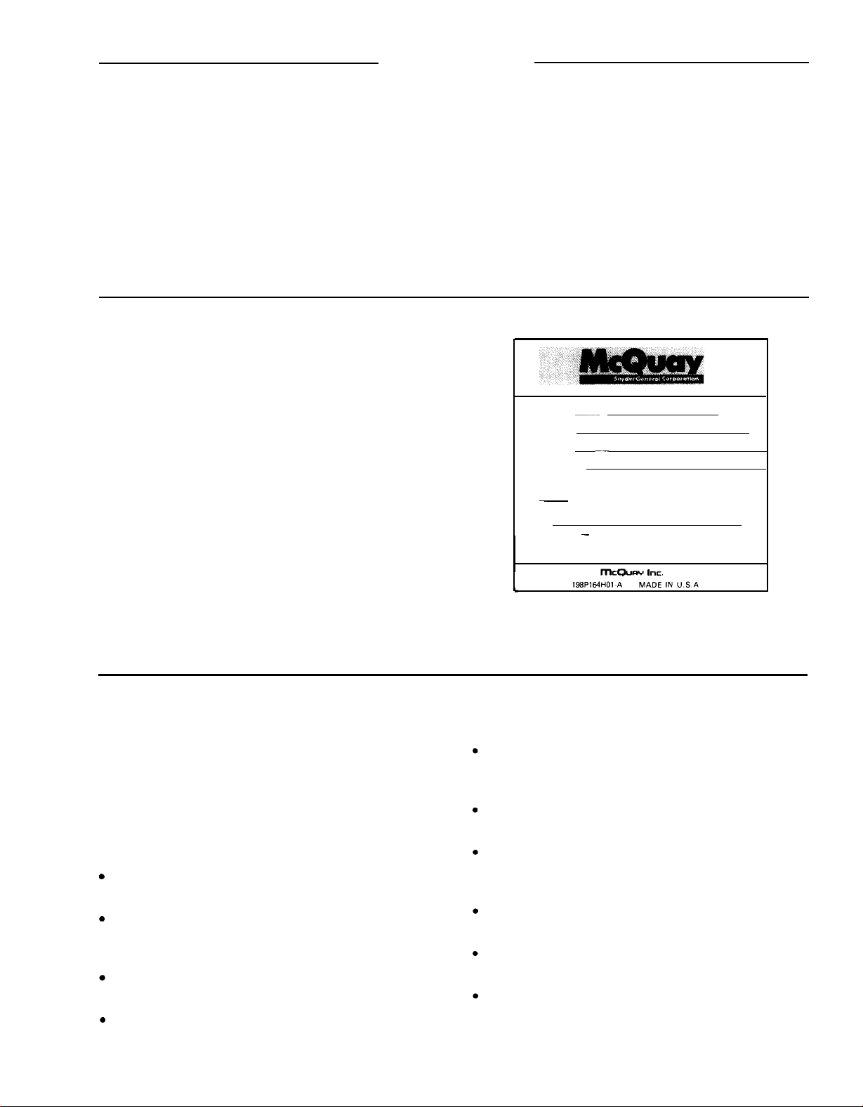
In addition to the unit nameplate shown in Figure 1,
each component has a nameplate affixed with certain
data for the installer, including electrical data for the
compressors and oil pumps.
sentatives, and normally consists of properly setting
the unit in place and connecting the necessary wiring
and piping services to the machine.
All McQuay Templifiers must be started only by a
McQuay Service Representative. The installer should
make no attempt to start the machine before the
complete system checkout has been made by McQuay
and the unit has been initially started.
MODEL
STYLE
SERIAL
S.O. NO.
~~~~
~_
FACTORY CHARGED
~
LBS. REFRIGERANT
LEAK TEST PRESSURE 100 PSIG.
MOTOR
- COMPRESSOR
AND OVERLOAD PROTECTION FIELD
SUPPLIED. SEE SPEC.
UNIT NAMEPLATE
CONTROLLER
PE-D4
FIGURE 1
_
SAFETY CONSIDERATIONS
McQuay equipment is designed to provide safe and
reliable service when properly installed and operated
within the design specifications. The installer and
operator should observe good safety precautions to
prevent damage to the equipment or injury ‘to personnel. Particular attention should be given to the
following:
.
Do not climb on the unit or step on electrical or
refrigerant lines.
.
Never exceed specified test pressures. Verify allowable test pressures by checking the instruction
literature and/or the equipment nameplates.
.
Do not use oxygen to purge or to pressurize the
unit.
.
Do not obstruct or valve off any safety or relief
devices.
Never open valves or connections under pressure in
a way that can cause loss of refrigerant or oil or
create a personnel hazard.
Nameplate and warning/instruction tags should not
be removed.
Fluorocarbon refrigerants must be handled with
caution and release to the atmosphere should be
minimized.
Use only the correct refrigerant
nameplate.
Only qualified electricians should make electrical
installations.
Make certain that rigging equipment is adequate for
the unit weights.
-
consult the unit
Page 4
RECEIVING AND HANDLING
INSTALLATION
The unit should be inspected immediately after receipt
for possible shipping damage.
All
McQuay
Centrifugal Templifier Heat Pumps are
shipped F.O.B. factory and all claims for handling and
shipping damage are the responsibility of the
consignee.
Leave the shipping skid in place until the unit is in its
final position. This will aid in handling the equipment.
Extreme care should be used when rigging the equipment to prevent damage to the control center, or
refrigerant piping.
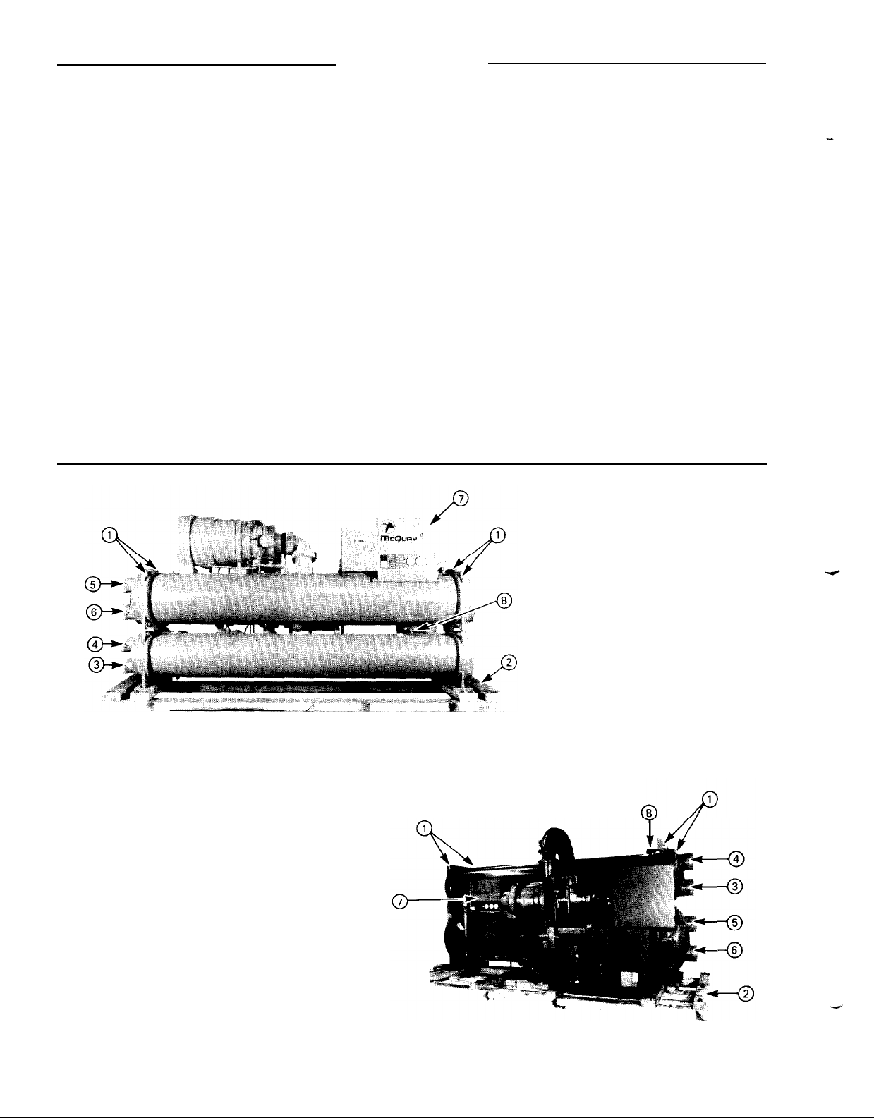
On units with top mounted compressors, the unit can
be lifted by fastening the rigging hooks to the 4
corners of the evaporator where the rigging eyes are
located. (See Figure 2.) Spreader bars should be used
between the rigging lines to prevent damage to the
control center and other components.
On units with side mounted compressors, the unit can
be lifted by the three corner fitting eyes and the
extended eye at the compressor end. The center of
gravity is located approximately where the discharge
line enters the upper condenser shell. Adjust cable or
chain lenghs accordingly. The compressor support is
not designed to support the full weight of the unit.
Therefore, unit must be lifted so that it is level or
canted to assure that the compressor supports leave
the ground first and touch down last. Spreader
bars are a must. (See Figure 3).
For equipment weights for rigging and installation
requirements, refer to the certified equipment data.
1.
2.
3.Condenser Water
4.Condenser Water
FIGURE 3
SIDE MOUNTED COMPRESSOR UNITS
Lifting Eyes
Shipping Skid 6.Source Water - Out
-
In 7.
-
Out 8.
Source Water - In
5.
Control Center
Condenser Relief Valves
TOP MOUNTED COMPRESSOR
FIGURE 7.
UNITS
Page 5

LOCATING AND MOUNTING
INSTALLATION
The unit should be mounted on a level concrete or
steel base and should be located so as to provide
service clearance at one end of the unit for possible
removal of evaporator tubes and/or condenser tubes.
Clearances required are 16 feet for units with 14 foot
long shells, 14 feet for units with 12 foot shells, and
feet for units with 8 foot long shells. Evaporator and
condenser tubes are rolled into the tube sheets to
permit replacement if necessary. Clearance at all other
points, including the top, is 3 feet.
Make certain that the floor or structural support is
adequate to support the full operating weight of the
complete unit.
WATER PUMPS
The use of 3600 rpm or two pole pump motors is not
recommended. It is not uncommon to find these
pumps operate with objectionable noise and vibration.
It is also possible to build up a frequency beat due to
the slight difference in the operating rpm of the pump
motor and the McQuay centrifugal motor. McQuay
encourages the use of
motors whenever possible.
1750
rpm or four pole pump
10
Rubber Shearflex or “lsomode”, pads are supplied
with unit, for use under each corner of the base
members. These pads are packed in the control box
for shipment.
It is not normally necessary to bolt the unit to the
mounting slab or framework; but should this be
desirable,
the unit supports at the four corners and under the
compressor base on the side mounted compressor
units. The unit must be level.
The condenser is connected with the coolest water
entering at the bottom.
The piping should be supported to reduce the weight
and strain on the fittings and connections. Piping
should also be adequately insulated. A cleanable 20
mesh water strainer should be installed at both inlets.
Sufficient shut-off valves should be installed to permit
draining the water from the evaporator or condenser
without draining the complete system.
1-1/8
inch mounting holes are provided in
EVAPORATOR AND CONDENSER
WATER PIPING
All Templifier evaporators and condensers come
equipped with groove-type mechanical clamp or flange
connections. The installing contractor must provide
matching mechanical connections of the sizes given in
the system dimension and capacity tables. NOTE: IF
WELDING IS TO BE PERFORMED ON THE
MECHANICAL OR FLANGE CONNECTIONS, THE
SOLID STATE TEMPERATURE SENSOR AND
THERMOSTAT BULBS MUST BE REMOVED FROM
THE WELLS TO PREVENT DAMAGE TO THOSE
COMPONENTS.
Small water pressure test valves or pipe plugs are
provided at both the inlets and outlets of the vessel
heads. The test valves permit the water flow pressure
drops to be checked. The pressure drops and flow
rates for the evaporator and condenser are specified on
each installation.
Figures 2 and 3 show the inlets and outlets of the
evaporators and condensers. The evaporator is connected with the warmest water entering at the top.
NOTE: NEITHER THE EVAPORATOR NOR THE CON-
DENSER IS SELF-DRAINING: BOTH MUST BE
BLOWN OUT. THE PIPING SHOULD ALSO INCLUDE
THERMOMETERS AT THE INLET AND OUTLET
CONNECTIONS AND AIR VENTS AT THE HIGH
POINTS.
In cases where the water pump noise may be objectionable, rubber isolation sections are recommended at
both the inlet and outlet of the pump. In most cases,
it will not be necessary to provide vibration eliminator
sections in the condenser inlet and outlet water lines;
but where noise and vibration are critical (for example,
where a pipe chase goes through walls), they may be
required. A bypass around the evaporator and/or
condenser must be provided where uninterrupted
source and/or process water flow is required.
Where a cooling tower is used to supply source water,
a flow balancing valve is required when the evaporator
does not have full flow.
OIL COOLER PIPING
Templifier oil coolers normally utilize water for removing heat from the lubricating oil. The water source
must never exceed
gOoF.
In some applications,
refrig-
5
Page 6

INSTALLATION
erant cooled oil coolers are provided and are completely piped up in the factory. Refrigerant cooling is
usually limited to the
TP050
models.
Water Cooled Oil Coolers
When water is to be the coolant, the oil cooler is
factory mounted with the oil piping installed. Water
piping for the oil coolers must be installed in the field
according to good piping practice and should include:
stop valves to isolate the cooler for servicing, cleanable
strainer
(40
mesh maximum), balancing valve to adjust
water flow, solenoid operated water shut-off valve
wired in accordance with Field Connection Control
Diagram, and a drain valve or plug. Water supply for
the oil cooler may be obtained from:
A. Source Water Circuit. See Figure 4.
B. Independent source, such as city water.
C. Cooling tower makeup if the flow is adequate and
continuous and the temperature never exceeds
90°F. See Figure 5.
TABLE 1
1
Maximum Oil Cooler Water Requirements
Model
TEH063
TEH079
TEH100
TEH126 16.0
*Pressure drop through two oil coolers with water sides piped in
series
-
TEH 126 only.
When the oil cooler is piped into the source water
supply, its water piping should be connected across
the source water pump so that the full pressure
differential of the pump is maintained across the cooler
system at all times the pump is running. This is the
recommended arrangement, and most systems will
accommodate it. For those installations where it could
be desirable to pipe the oil cooler system across the
evaporator, this may be done providing the water
pressure drop through the evaporator is greater or
equal to the oil cooler pressure drop.
Under no circumstances should the oil cooler be piped
in parallel with a single pass evaporator. This will result
in inadequate cooling water to the oil cooler due to the
low evaporator pressure drop.
When supplied with city water, the oil cooler water
piping should discharge into an open drain to prevent
draining the cooler by siphoning. This water may also
And Pressure Drops
Maximum
Water Requirement
@
85 F Entering
GPM
8.0
8.0
12.25 5.2
Water
Pressure Drop Thru
Oil Coolers Only
PSI
1.8
1.8
10.4’
be used for cooling tower makeup by discharging it
into the tower sump from a point above the highest
possible water level.
On
R12
units, the water flow through the oil cooler
must be adjusted with the balancing valve so that the
temperature of oil supplied to the compressor bearings
(entering the compressor) is not less than 90°F nor
more than 120°F. On systems using source water for a
cooling medium, the leaving oil temperature should be
on the low side of the acceptable temperature range
when operating with the coldest water.
For
R114
units oil temperatures are normally higher.
For settings consult special instructions furnished with
the unit.
I
I
FIGURE 5
OIL COOLER PIPING
On some units, oil cooler water solenoid valves are
factory furnished. On those units where the solenoid
valve is required and not furnished, the installing
contractor must supply the solenoid.
Refrigerant Cooled Oil Coolers
On those Templifier units furnished with refrigerant oil
cooling, the shut-off and flow control are built into the
refrigerant piping.
Subcooled liquid from the condenser is fed to the oil
cooler through an oil temperature control valve whose
control bulb is located on the oil line leaving the oil
cooler. The gas
the evaporator. Refrigerant flow is controlled to
tain an oil temperature of approximately
R12 Templifiers. Oil Coolers in
at higher temperatures.
-
liquid mixture returns to the inlet of
R114
Templiers operate
main-
90-lOOoF
in
6
Page 7

INSTALLATION
1.
CEO63 Compressors
2.Lube Boxes
3.Suction Shutoff Valve
4.Condenser Relief Valves
5. Expansion Valves
6. Oil Pumps
7.Oil Level Sight Glass
8.Hot Gas Bypass
9.
Oil Coolers
10.
Discharge Check Valve
11. Motor Cooling Liquid Line
12. Motor Cooling Liquid Filter-Drier
TFH063
VENT PIPING
As a safety precaution, each system is equipped with
pressure relief valves located on the condenser and on
the evaporator for the purpose of relieving excessive
refrigerant pressure to the atmosphere. Many local
codes require that relief valves be vented to the
outside, and this is desirable installation practice for all
installations. NOTE: Remove plastic thread protectors
from the inside of the valves prior to making pipe
connections. Whenever vent piping is installed, the
lines should be run in accordance with local code
requirements; or where local codes do not apply, ANSI
B9-1
-Sec. 12 code recommendations should be
followed.
Current condenser design incorporates two relief
valves
the two valves. (See Figure 7). When piping the vent
line to a dual valve set, it may be sized for one relief
valve and piped to both valves. If one relief valve of the
two valve set fails, the shut-off valve may be used to
isolate the faulty relief valve, easing replacement. On
(1
set) with a
3-way
shut-off valve separating
FIGURE 6
(Rear View)
13.
CondenserInlet
14.
CondenserOutlet
15.
EvaporatorInlet
16.
Evaporator
17. Motor Terminal Cover
18. Liquid Line Shutoff Valve
Outlet
Condenser Relief Valve Set
1. #l Relief
2.
3.
4.
larger capacity condenser designs, two sets of dual
relief valves are used. These vents must be sized for
the total of two valves.
Valve
#2
Relief
Valve
Relief Valve
3-Way
Access Valve
3-Way
Shutoff
FIGURE 7
Page 8

THERMAL INSULATION
INSTALLATION
Factory installed thermal insulation is furnished on all
parts of the Templifier unit as needed to prevent
sweating, to retain thermal efficiency, and to protect
operating personnel from hot surfaces.
ELECTRICAL
Wiring, fuse and wire size must be in accordance with
information provided in the Electrical Data. Standard
NEMA motor starters require modification to meet
McQuay specifications. Refer to Electrical Data supplied with the unit for details.
IMPORTANT: The voltage of these units should be
within the limitation of plus or minus
voltage unbalance between phases must not exceed
3%. Since a 3% % voltage unbalance will cause an
approximate 25% increase in motor temperature, it is
most important that the unbalance between phases be
at a minimum.
NOTE: Do not make final power connections to the
starter until wiring has been checked and approved by
an authorized McQuay Service Representative. Under
no circumstances should the compressor be brought
up to speed unless proper phase sequence and rotation
have been established. Serious damage may result if
the compressor starts in the wrong direction. Jog the
machine to check rotation using the sight glasses on
the rear motor cover to observe direction.
Power Wiring
Power wiring to the compressor must be in proper
phase sequence. Motor rotation is set up for clockwise
rotation facing motor end cover with phase sequence
of l-2-3. Care should be taken that proper phase
sequence is carried through the starter to the compressor. With the phase sequence of l-2-3 and
connected to T1 and T6, L2 connected to T2 and T4,
and L3 connected to T3 and T5, rotation is proper. See
diagram in terminal box cover.
T**063/079/100/126
10%,
and the
Care should be taken not to tear, damage or remove
any of this factory insulation.
All field piping connections to the Templifier should be
insulated by the installer if required by good practice
and personnel safety.
CAUTION: Wiring connection to compressor terminal
studs must be made with copper lugs and copper wire.
Power Wiring
All
T**048/050
factory wired and mounted star delta starter equipped
with ambient compensated quick trip overloads, factory set at 1
be in accordance with information located in the elec-
trical data supplied with the unit
cal Data pertaining to your unit.
The power wiring to the compressor starter must be in
proper phase sequence. See second paragraph under
T**063/079/100/126
All units are factory equipped with open transition
starters. Closed transition starters are supplied on a
special order basis. Transition should be set to 15
seconds.
15% F.L.A. Wiring, fuse and wire size must
T**048/050
units are normally supplied with a
or the
McQuay Electri-
Power Wiring.
Control Wiring
The control circuit on the McQuay
and 126 Templifiers is designed for 1 15 volts. Power
should be supplied from a separate circuit and fused at
10 amps. (See Table 2). The control circuit on the
TP048/050
power is provided to the control panel by a .75 or 1
KVA 1 15 volt transformer supplied and mounted in the
starter package.
L1
unit is also designed for 115 volts, but
TABLE 2 MAXIMUM CONDUCTOR LENGTH*
T**063/079/100
Phase sequence can be determined by using GE No.
546703265 phase sequence meter or equal. Before
connecting the starter load leads to the compressor
terminals and while checking the field connection
wiring, the transition timer in the starter should be
adjusted to make the transition in 15 seconds. This
should be reset when the compressor is put on the
line. The timer should be adjusted to actuate (discon-
nect Star winding connection and connect Delta)
when the motor has come up to speed and before any
speed reduction occurs.
-I
l Maximum length is distance conductor will traverse between
control power source and the unit control panel. Wire size based
on voltage drop not to exceed 3 percent.
Panel terminal connectors will accommodate wire size up to 10
AWG, larger conductors will require an intermediate junction box.
The disconnect switch should be tagged to prevent
current interruption. SWITCH IS TO REMAIN ON AT
ALL TIMES IN ORDER TO KEEP OIL HEATERS
8
Page 9

INSTALLATION
b
8
1.
CEO63 Compressor
2.Evaporator
3.Condenser
4.Relief Valves
5.
Control Panel
6.
Lube Box
Oil Pump
7.
Oil Level Sight Glass
8.
Discharge Line
9.
Hot Gas Bypass
10.
Expansion Valve
11.
OPERATIVE AND PREVENT REFRIGERANT FROM
ACCUMULATING IN OIL.
The control center off-on switch should be turned to
the “Off” position any time compressor operation is
not desired.
If the control voltage is supplied by a transformer, the
transformer should be rated at 2 KVA, with an inrush
rating of 12 KVA minimum at 80% power factor and
95% secondary voltage. For control wire sizing, refer
to the N.E.C. article 215 and 310. In the absence of
complete information to permit calculations, the voltage drop should be physically measured.
Control Interlocks
Water flow interlock terminals are provided on the
control center terminal strip. See field connection
diagram in the Electrical Data or in cover of control
center for proper connections.
The purpose of the water flow interlocks is to prevent
compressor operation until both the source water and
condenser water pumps are running and flow is
proven.
12.
Liquid Line Shut-Off Valve
13.
Oil Cooler
14.
Motor Liquid Cooling Line
15.
Motor Terminal Cover
16.
Discharge Check Valve
FIGURE 8
TEH063
Operation of the source water pump may be to cycle
the pump with the compressor or it may be operated
continuously. The hot water (condenser) pump normally will be run continuously. The holding coil of
the cooling tower pump motor starter must be rated at
115 volts 60 Hz with a maximum 25 volt-ampere rating.
All interlock contacts must be rated for no less than 10
inductive amps. The alarm circuit provided in the
control center utilizes 115 volts. The alarm used should
not draw more than
10
volt-amperes.
TESTING CONTROL CIRCUIT
The installing contractor should complete all field
connections to the Templifier control panel after which
he should check out all remote interlocks for proper
operation. Do not disturb the internal wiring of the
control center or change the factory settings of
operating and safety controls.
At the time of startup the
will completely check out the power and control
circuits. Final power connections to the compressor
should be made only after the
inspection.
McQuay
Service Technician
McQuay
pre-startup
9
Page 10

@--
@-----
INSTALLATION
10
Q
CE126 Compressor
1.
Motor Terminal Cover
2.
Lube Box
3.
Oil Coolers
4.
Expansion Valves
5.
Liquid Line Shut-Off Valve
6.
7.Evaporator
8.Condenser
9.Control Center
Discharge Check
10.
Oil Pump
11.
REPAIR OF SYSTEM (If Necessary)
Pressure Testing
No pressure testing is necessary unless some damage
has been incurred during shipment. Damage may be
determined upon a visual inspection of the exterior
piping assuring no breakage occurred or fittings
loosened. Panel gauges should show a positive pressure (except R-114 units in cold locations). If no pres-
sure is evident on the gauges, a leak may have oc-
curred discharging the entire refrigerant charge. In this
case, the unit should be leak tested to determine the
location of the leak. R-114 units must be above an
ambient of
Leak Testing
50°F
to show a positive pressure.
FIGURE 9
TEH 126
Oil Level Sight Glass
12.
13.
Oil Sump
Oil Cooler Water Lines
14.
Valve
Motor Liquid Cooling Line
15.
Condenser Relief Valves (Hidden)
16.
test pressure given above. When the test pressure is
reached, disconnect the gas cylinder.
If any leaks are found in welded or brazed joints or if it
is necessary to replace a gasket, relieve the test
pressure in the system before proceeding. For copper
joints, braze alloy is recommended.
After making any necessary repair, the system should
be evacuated as described in the section following.
Evacuation
After it has been determined that there are no
refrigerant leaks, the system should be evacuated
using a vacuum pump with a capacity of approximately
3 cu.
ft./min.
and that will reduce the vacuum to at
least 1 millimeter (1000 microns).
In the case of loss of the entire refrigerant charge, the
unit should be checked for leaks prior to charging the
complete system. This can be done by charging
enough refrigerant into the system to build the
pressure up to approximately
1-
psig and adding
sufficient dry nitrogen to bring the pressure up to a
maximum of 125 psig and then leak test with a Halide
or electronic leak detector. WATER FLOW THROUGH
THE VESSELS SHOULD BE MAINTAINED ANY TIME
REFRIGERANT IS ADDED OR REMOVED FROM THE
SYSTEM. CAUTION: DO NOT USE OXYGEN TO
BUILD UP PRESSURE AS A SERIOUS EXPLOSION
CAN RESULT. A pressure regulating valve should
always be used on the nitrogen drum being used to
build up the system pressure. Also, do not exceed the
A mercury manometer, electronic or other type of
micron gauge should be connected at the farthest
point from the vacuum pump. For readings below 1
millimeter, the electronic or other micron gauge should
be used.
The triple evacuation method is recommended and is
particularly helpful if the vacuum pump is unable to
obtain the desired 1 millimeter of vacuum. The system
is first evacuated to approximately 29 inches of
mercury. Enough refrigerant vapor is then added to the
system to bring the pressure up to zero pounds.
Then the system is once again evacuated to approxi-
mately 29 inches of mercury. This is repeated 3 times.
The first pull down will remove about 90% of the
10
Page 11

INSTALLATION
non-condensables, the second about 90% of that
remaining from the first pull down and after the third
only 1
/10
of 1% of the non-condensables will remain.
Charging the System
All Templifier Heat Pumps are leak tested at the
factory and shipped with the operating charge of
refrigerant as indicated on the unit nameplate. In the
event the refrigerant charge was lost due to shipping
damage, the system should be charged as follows after
first repairing the leaks and evacuating the system.
Connect the refrigerant drum to the gauge port on
the liquid shut-off valve and purge the charging line
between the refrigerant cylinder and the valve. Then
open the valve to the mid position.
Turn on both the supply water pump and source
water pump and allow water to circulate through the
condenser and the evaporator.
If the system is under a vacuum, stand the refrigerant drum with the connection up and open the drum
and break the vacuum with refrigerant gas.
With a system gas pressure higher than the equiva-
lent of a freezing temperature, invert the charging
cylinder and elevate the drum above the condenser.
With the drum in this position, valves open, water
pumps operating, liquid refrigerant will flow into the
condenser. Approximately 75% of the total requirement estimated for the unit can be charged in this
manner.
After 75% of the required charge has entered the
condenser,
reconnect the refrigerant drum and
charging line to the service valve on the evaporator.
Again purge the connecting line, stand the drum
with the connection up and place the service valve in
the open position.
The normal ambient pressure of
R114
refrigerant is
so low that a refrigerant pump may be desirable and
helpful in charging with that refrigerant.
Important
At this point, the charging procedure should be inter-
rupted and pre-start checks made before attempting
to complete refrigerant charge. The compressor must
not be started at this time.
Operation and Maintenance manuals pertaining to the
individual units are available from your local McQuay
Service Representative.
PRE-START SYSTEM CHECKLIST
SOURCE (EVAPORATOR) WATER
Cooling tower flushed, filled and vented
Water system filled, vented (if used)
Pumps installed, (rotation checked) strainers cleaned
Controls (3-way valves, by-pass valves, etc.) operable
Water system operated and flow balanced to meet unit design requirements
HOT (CONDENSER) WATER
Piping complete
Water system filled, vented (if
Pumps installed, (rotation checked) strainers cleaned
Controls (3-way valves, face and by-pass dampers, by-pass valves, etc.) operable
Water system operated and flow balanced to meet unit requirements
used)
ELECTRICAL
-
service completed, but not connected to control panel
*Power leads connected to starter; load leads run to compressor ready for connection when
Service Engineer is on hand for start-up
(Do not connect to starter or compressor terminals)
All interlock wiring complete between control panel and complies with specifications
Starter complies with specifications
“Oil cooler solenoid wired to control panel as shown on wiring diagram
Pump starter and interlock wired
Cooling tower fans and controls wired
Wiring complies with National Electrical Code and local codes
*Condenser pump starting relay
MISCELLANEOUS
Oil cooler water piping complete. (Units with water cooled oil coolers
Relief valve piping complete
Thermometer wells, thermometers, gauges, control wells, controls, etc. installed
A minimum system load of 25% of machine capacity is available for testing and
adjusting controls
(if
used)
(HWR)
installed and wired.
only)
No
Not
Applicable
11
 Loading...