

Page 1
Page 2

Page 3
APPLICATION
The operation and maintenance procedures presented in this
manual apply to the models
TEH050-126.
Reference to the
installation manuals for these units should be made for details
pertaining to receiving and handling, installation, piping and
wiring, and preparation for initial start up.
All McQuay Centrifugal Templifiers are factory tested prior
to shipment and must be initially started by a factory trained
McQuay Service technician. Failure to follow this start-up procedure may affect the equipment warranty.
The standard warranty on this equipment covers parts
which prove defective in material or workmanship. Specific
OPERATION
OPERATOR RESPONSIBILITIES
It is important that the operator become familiar with the
equipment and the system before attempting to operate the
Templifier.
In addition to reading this manual the operator should study
all the control diagrams furnished with the unit so that he
understands the starting, operating and shut-down sequences
as well as the safety shut-down modes.
When the McQuay Service technician performs the initial
start-up of the Templifier he will be available to answer any
questions and to instruct in proper operating procedures.
It is recommended that the operator maintain an operating
log for each individual unit. In addition, a seoarate
maintenance log should be kept of the periodic maintenance
details of this warranty can be found in the warranty state-
ment furnished with the equipment.
In the application of Templifiers, each unit is designed for
specific heat recovery conditions to achieve the highest possible performance. In order to maintain the design performance
levels, the equipment must be operated and maintained according to the procedures in this manual. The operating and
maintenance procedures in this manual will apply equally to
both TEH and THH models unless specifically noted. For
simplicity only the TEH designation will be used.
and servicing activities.
This McQuay centrifugal Templifier represents a substan-
tial investment and deserves the attention and care normally given to keep this equipment in good working order. If the
operator should encounter abnormal or unusual operating
conditions, it is recommended that a McQuay Service technician be consulted.
McQuay conducts training for centrifugal operators at its
factory Training Center several times a year. These sessions
are structured to provide basic classroom instruction and include hands-on operating and troubleshooting exercises. For
further information, contact vour
McQuav reoresentative.
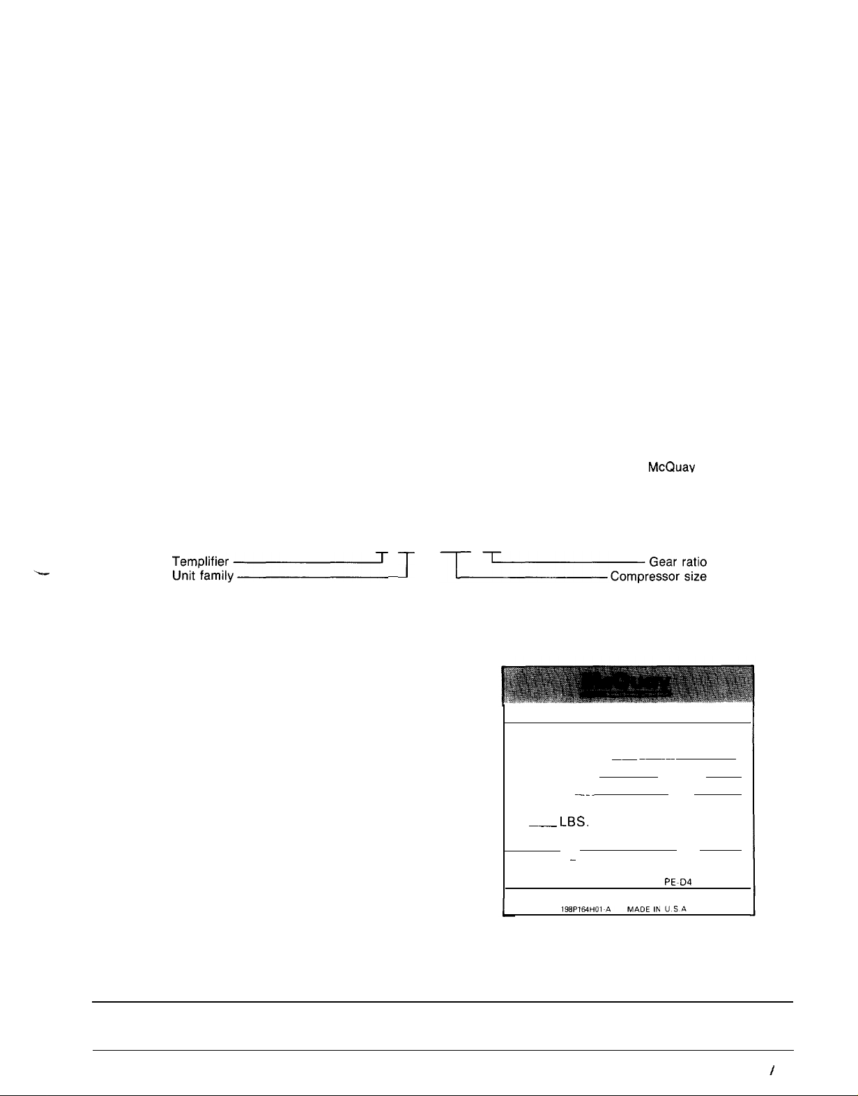
MODEL CODE
T EH
~~~;;y~
T
NOMENCLATURE
Each centrifugal Templifier is assigned a set of identifying
numbers which are used to describe the unit features and
to identify each individual unit. These four-number groups
are stamped on each unit nameplate. A typical nameplate
is shown in Figure 1.
The first number is the unit model number, this identifies
the unit. The second is the unit style number, followed by
a serial number and a shop order number (S.O.). The unit
nameplate is also stamped with the type and operating charge
of refrigerant.
All inquiries pertaining to operating and servicing of this
unit should include all identification numbers.
Each of the individual components also have nameplates
to provide certain necessary information to the installer and
the operator.
The compressor nameplate identifies the compressor
model, style and serial numbers and includes the electrical
characteristics of the compressor motor. The CEO50 com-
pressor nameplate also shows the oil pump electrical
characteristics.
The condenser and evaporator vessels have nameplates
stamped with the maximum working pressure of the vessel.
It should be noted that the vessel relief valve maximum settings coincide with the maximum refrigerant side vessel working pressure.
063K AR
FIGURE
1. Unit Nameplate.
MODEL
STYLE
SERIAL
S.O. NO.
~~~~~~~
~
~_.__
FACTORY CHARGED
~_
LSS. REFRIGERANT-
LEAK TEST PRESSURE 100 PSIG.
MOTOR - COMPRESSOR CONTROLLER
AND OVERLOAD PROTECTION FIELD
SUPPLIED. SEE SPEC.
PE-D4
NOMENCLATURE CHANGE: The model nomenclature TPE and TPH has been changed to TEH and THH respectively. TPE
and TPH are synonymous with TEH and THH respectively.
IM 315
I
Page 3
Page 4
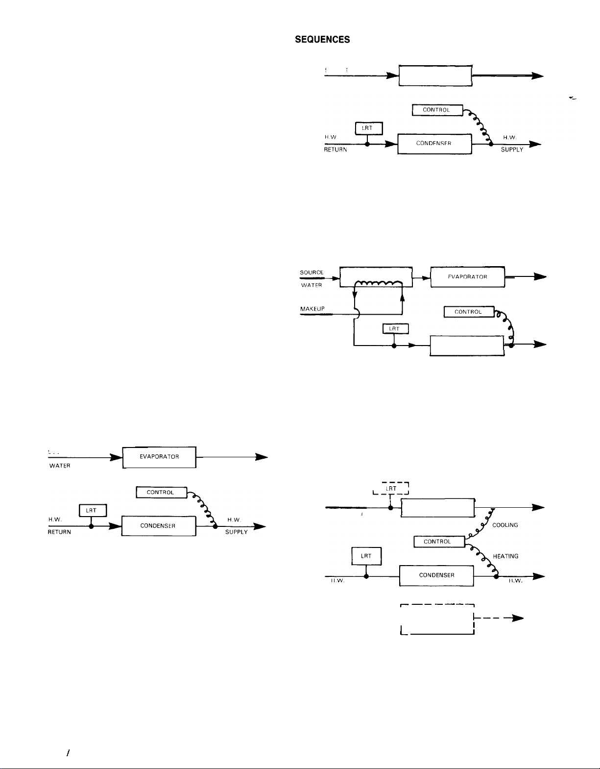
OPERATING
The operation of a Templiifer is similar in some ways to that
conventional chiller, Heat is picked up by the evaporator and
transfered to the condenser via the conventional refrigeration cycle. Source fluid temperatures entering the evaporator
are usually higher than chilled water systems, consequently, the water leaving the condenser is at higher temperature
and thereby more useful for heating purposes.
Although there are no two Templifier control schemes ex-
actly alike, there are four basic control arrangements, and
most applications are adapted from one of them. They are:
1. Process or Service Water Heating
2. Environmental Heating
3. Boiler Feedwater Heating
4. Combination Heating/Cooling
When in automatic control mode, the compressor is nor-
mally cycled on and off in responce to a Load Recycling Thermostat (LRT); during operation the compressor capacity is
controlled by as control module located in the control center.
The sensing point for these controls varies with the application. Schematics of the four arrangements are shown in
Figures 2
-
5.
During all phases of operation, the critical functions of the
Templifier are under constant surveillance by the safety controls Abnormal conditions will cause the chiller to be shut
down and usually will require some corrective action to prevent recurrence. A set of panel lights on the control panel
will indicate the cause of shutdown. For the protection of the
equipment, the operator should determine the exact cause
of shutdown and correct the situation prior to operating the
unit again.
PROCESS/SERVICE WATER HEATING
This system is applied to process heat recovery and service
water installations when the requirement is to maintain a constant hot water temperature. The sensor for capacity regulation is located in the condenser leaving water, and the com-
pressor on/off control (LRT) responds to condenser entering
temperature. (See Figure 2).
FIGURE 2.
SOURCE
>
FIGURE 3.
SOURCE
WATER
EVAPORATOR
BOILER FEEDWATER HEATING
This system utilizes a waste heat source to preheat makeup
water for heating
or process
boilers. Capacity control is usually set at maximum design temperature and the Templifier will
normally operate at or near full load to take full advantage
of the available waste heat. The load recycling thermostat
functions more like a safety control since the makeup water
should not rise to cutout temperature. (See Figure 4).
FIGURE 4.
HEAT EXCHANGER
WATER
CONDENSER
w
TO BOILER
*
PREHEATER
COMBINATION HEATING/COOLING
The combination system operates as a chiller for comfort cooling during summer periods and as a heating unit in winter
heating periods. During heating mode, a waste heat source
is channeled through the evaporator. Compressor on/off control is from thermostats (LRT) in the evaporator inlet for cooling and in the condenser inlet for heating. This system is
sometimes fitted with a separate cooling tower condenser for
summer heat rejection. (See Figure 5
FIGURE 5.
r
1~i-i
SOURCE OR
CHW RETURN
EVAPORATOR
).
*
ENVIRONMENT HEATING
For space heating applications, the compressor capacities
may be controlled to maintain a constant return water
temperature. This system effectively varies (or resets) the
temperature of the heating water with system load changes.
Compressor starting is controlled from condenser entering
water temperature, whereas compressor shutdown is signaled from condenser leaving temperature. (See Figure 3).
For the proper operation of the centrifugal Templifier, a
thorough understanding of the control is essential.
The controls are housed for the most part in the Control
Center and in the Lube Box, both of which are mounted on
the Templifier assembly.
Page 4
I IM 315
RETURN
CONTROL SYSTEMS
A complete summary of the control components presented
in Table 1 identifies each control, its location and setting,
along with a brief description of its purpose in the control
scheme. Most of these controls are standard on all units while
a few may be special purpose or optional devices. Using this
-4
------7
OPTIONAL
TOWER
/_
CONDENSER
SUPPLY
I
I--1
--)
Page 5
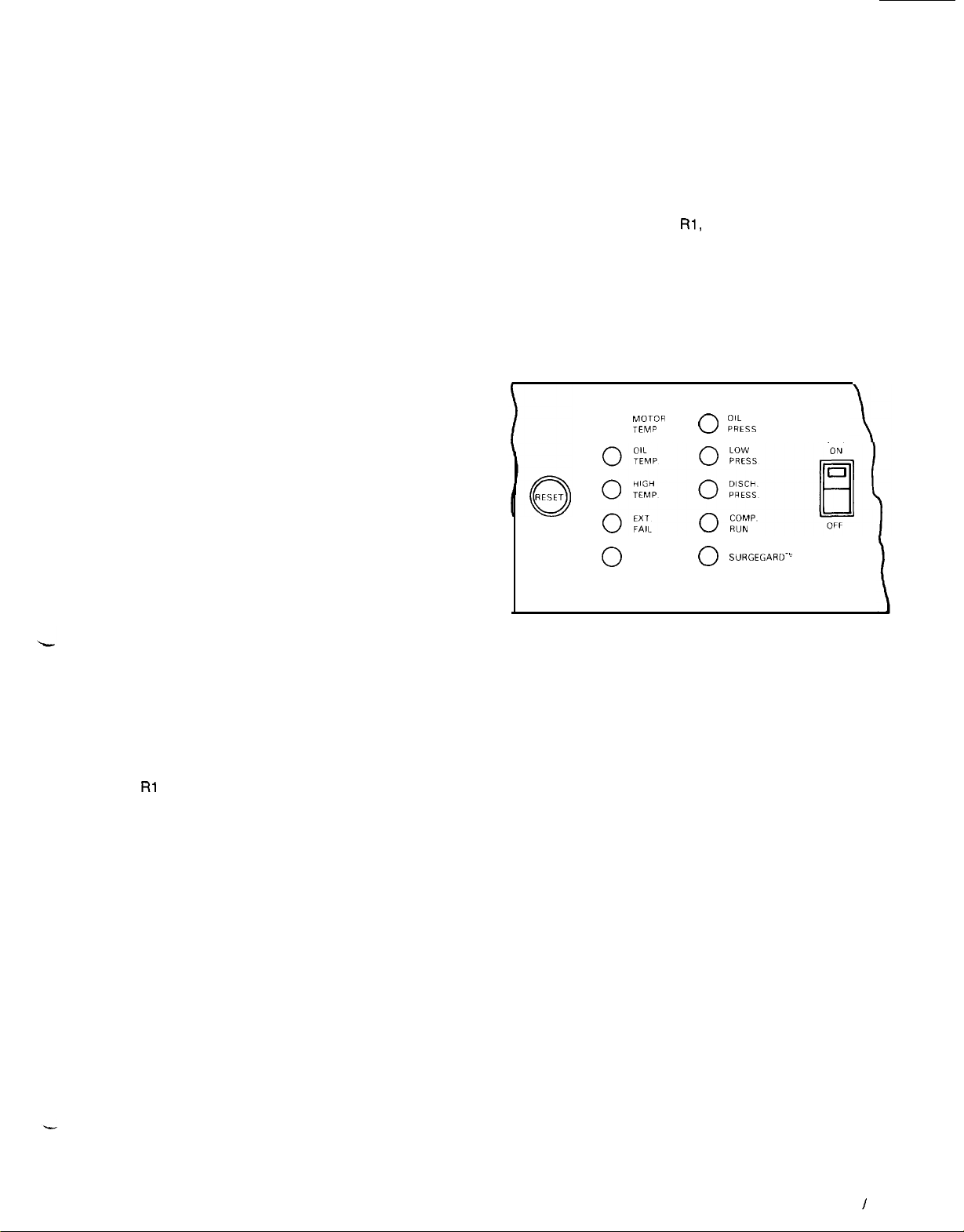
chart in conjunction with the control diagram shipped with
the unit will aid in understanding the various control modes.
For the purpose of describing the controls, they have been
divided into two categories Operating Controls and
Protective Controls and in each group, certain of the
important controls will be reviewed in some detail. There are
a dozen or so relays in the control center which respond to
another controlling device to open or close circuits. These
relays can be identified by the operator from the control
diagram.
OPERATING CONTROLS
The operating control group consists of devices which serve
specific functions in starting, operating and shutting down
the centrifugal compressor during normal operating conditions. For this description it is assumed that the system conditions monitored by the safety and protective controls are
normal and that those controls are positioned for running.
The ON-OFF switch on the control panel provides a means
of manual control to energize or de-energize the operating
circuit. When this switch is turned on, its self-contained light
will energize and the control circuit is ready for automatic
operation of the compressor.
The Load Recycling Thermostat (LRT) sensing water
temperature will cycle the compressor on the line when the
water temperature reaches the ON control point, and will shut
the compressor down when the water temperature drops to the OFF setpoint. The setting procedure is detailed in the adjustment section of this manual.
To assure that the compressor will not be started too frequently, the Time Delay Relay (TDR) will prohibit a restart
within 20 minutes of the last shutdown. This timing is for the
protection of the compressor motor and is not adjustable. It
is classified as an operating control because it functions as
a part of the starting sequence.
On R12 units, once the TDR contacts close, the oil pump
is started and the Prelube Timer (PLT) is energized to assure
oil pumping and bearing lubrication for a fixed time prior to
compressor start. On
after the vane closed switch (VC) closes. At the same time,
the oil heaters which have been energized during the
compressor-off period are now shut off.
Simultaneous with starting the oil pump, the Oil Cooler
Solenoid (OCS) in R12 units is energized, permitting coolant
to flow through the oil cooler to remove the heat generated
by the compressor bearings once the compressor starts.
When RI 14 is used the OCS is energized simultaneously with
oil pump starting providing the vane closed switch (VC) is
closed.
For R12 units at the end of the prelube period the control
circuit is completed up to the Vane Closed switch (VC) which
monitors the position of the compressor capacity control
vanes. This switch permits compressor starting only when
the vanes are in the fully closed position. On
prelube period starts as soon as the vane closed switch
closes.
To complete the control circuit for compressor starting, the
pump interlocks and water flow interlocks for the condenser
water and source water must be closed.
Once the compressor is started, the Control Module functions to load and unload the compressor in response to
changes in the water temperature. The Control Module will
be discussed in greater detail in a later section.
As the system toad reduces and the Control Module
unloads the compressor, the compressor will continue to run
until the LRT shuts off the machine when the water
temperature reaches the OFF set point.
The control panel has two lights which indicate the status
of control. The COMP. RUN light shows that the compressor
is running under normal control and the LOAD RECYCLE
light indicates the compressor has been taken off line by a
normal operating control and is waiting for a restart signal.
R114
units the PLT timing starts only
R114
units the
PROTECTIVE CONTROLS
Each McQuay centrifugal Templifier is equipped with a complement of safety controls to prevent the compressor from
starting under adverse conditions or to take the machine offline when abnormal or unsafe conditions develop during
operation.
In addition, there are a number of relay type devices which
operate to assure that the starting, operating and stopping
functions are carried out in proper sequence for the protection of the equipment. These relays can be identified on the
unit control diagram as
The control panel is equipped with several indicator lights
to provide the operator with a quick status condition when
the compressor is shut down. With the reference to Figure
6 it will be noted that there are eight safety signal lights to
describe some condition which has caused the compressor
to be shut down. In a fault condition only one light can be
energized at one time.
FIGURE 6. Control Panel Lights
MOTOR
TEMP
0
LOAD
0
RECYCLE
Most of these indicator lights are operated when some abnormal condition exists with the Templifier unit. Conditions
such as low suction pressure, high discharge pressure, low
oil pressure or temperature, high motor winding temperature
and surge condition may cause some damage to the equipment if allowed to continue uncorrected.
The troubleshooting guide on page 19 gives the operator
a comprehensive list of fault conditions and the probable
causes. This guide should be consulted whenever the com-
pressor is shutdown by a protective control.
Each unit is equipped with an “External Failure” light on
the control panel. When energized, this signal indicates the
compressor cannot run due to a control problem external to
the control panel. Faults in the condenser water/source water
circuits or in the compressor starter could trigger such an external failure signal. This feature helps the operator locate
control system problems. Causes and corrective actions are
further described in the troubleshooting guide.
The two most severe failures which can occur in a hermetic
centrifugal compressor are surge conditions and motor
failure. McQuay has developed highly reliable protective
systems to guard against both of these failures. An understan-
ding of each will be helpful to the operator in analyzing the
unit performance. Both Guardistor and Surgegard are safe-
ty protective systems developed by McQuay.
Guardistor Motor Protection-Positive protection against
motor overheating is provided by the Guardistor system. The
heart of the Guardistor protective circuit are the thermistors
embedded in the motor windings to sense motor winding
temperature. When the motor temperatures are normal, the
thermistors have low resistance which remains nearly cons-
tant up to a predetermined critical temperature. At this
temperature, a sharp increase in resistance causes the
Rl,
R2,. etc.
0
KS,
0 SURGEGARD-”
UNIT
Guar-
IM
315 I Page 5
Page 6
distor relay to drop out and cause the control circuit to stop
the compressor. Such failure causes a lockout mode requiring manual reset.
Surgegard-McQuay
uses Surgegard to sense the occurrence of surge condition and to stop the compressor before
the machine is damaged. The Surgegard relay will also prevent the compressor from restarting until the cause of the
malfunction has been corrected. Possible causes for surge,
or rotating stall condition, may be dirty condenser tubes or
cooling tower or pump malfunction, which acts to elevate the
system’s head. The Surgegard relay is the safety control
which shuts shuts off the compressor under abnormal conditions in the
TEH063,
079, 087, 100 and 126 Templifiers.
In the TEH050 the high temperature thermostat provides this
safety function. These controls are factory set and require
no field adjustment.
SAFETY CONTROL RESET
Certain safety controls in the Templifier control panel will lock
out automatically when operating conditions exceed trip set-
tings. As an example, if the refrigerant discharge pressure
leaving the compressor exceeds the trip setting of the high
pressure cutout switch, the compressor will be taken off-line
and cannot be restarted until the pressure has returned to
normal and the high pressure cutout has been manually reset.
In the control center several other safety functions also lock
out under abnormal operating conditions. These controls include the low pressure cutout, high discharge temperature
thermostat, high oil temperature switch, low oil pressure, high
suction temperature switch
(TEH/THHO63-126)
and external system failure.
(TEHITHH050 only), Surgegard
Each of these fault signals can be identified by the control
panel lights and all can be reset with the single RESET but-
ton on the front of the control panel when the fault has been
corrected.
In the event of electrical system power interruption, the
Templifier units
will lock
out and will not restart automatical-
ly. The EXT. FAIL light will go on when power is restored and
the RESET button must be manually reset to restore
automatic operation.
CONTROL COMPONENT SUMMARY
CONTROL
Alarm Relay
Chiller Pump,
Waterflow Interlocks Supplied
Cold Oil Temperature
Switch Section Temp.
Condenser Pump,
Waterflow Interlocks Supplied
Flow Switch
Time Delay
Guardistor Relay
Hot Gas Override
Solenoid
Hot Gas Solenoid
Hot Gas Thermostat
High Oil Temperature
Switch Temo. lR12) Section Temo. ina
High Pressure Switch
High Suction Temp.
Switch
High Discharge
Temp. Switch
Interval On Timer
Low Casting Temp.
Thermostat
Liquid Injection
Solenoid
Load Meter
Low Oil Temp.
Thermostat
Low Pressure
Switch
Pumpdown
Switch
Law Pressure
Override Switch
Control
SYMBOL SETTING
R9
CHWI None
COT
CWI
FSTD None
GR None
HGO None None
HGS None None
HGT
HOT
HP See Manual Switch
HST
HT
IOT
LCT
LIS
LM
LOT
LP
LPC
LPO
None
105°F Auto/Man
None
Field Set
140°F
Function Section Press.
150°F Auto/Man
225°F
Field Set
110°F
None None
None None Panel
130°F Auto
See
Function
2-5 psig Auto Side of
above LP
2 psig Auto
above LP
RESET
(Note 1)
Auto/Man
Auto/Man
Auto/Man
Auto
Auto/Man
None
Manual Switch
Manual Switch High
Ngne
Auto Temp.
Manual Switch
LOCATION
Relay
Section
Field Ext.
Switch
Field Ext.
Relay
Section
Relay
Section
Hot Gas
Piping
Hot Gas
Piping
Condenser
Frame
Temp.
Section
Section Temp.
Lead/Lag
Box
Section Temp.
Refrig.
Pipinq
Temp.
Section
Section
Panel one-time pumpdown
Switch None
Section
Surgegard Stops compressor when suction temperature exceeds setting prevents
SIGNAL
LIGHT
None
Fail
Oil
Fail
Ext.
Fail
Motor
Temp.
None
None
None
Oil
Disch.
None
Oil
None
None
Oil
Temp.
LOW
Press.
None
-
STANDARD APPLICATIONS
Actuates circuit for remote alarm.
Prevents chiller operation
flow is established.
Stops compressor if oil temperature entering compressor drops below
setting.
Prevents chiller operation until condenser water pump is energized
and flow is established.
Delays water flow bypass for three seconds to prevent false shutdown
Stops compressor motor when winding temperature exceeds limit.
Opens hot gas bypass at starting of 2nd compressor oil pump to
reduce starting head. Dual compressor units only.
Opens hot gas bypass from discharge to evaporator, providing false
evaporator load. Helps prevent surge conditions.
Energizes hot gas solenoid on drop in water temperature entering
evaporator (senses entering condenser water in Templifier).
Stops compressor if oil temperature entering compressor exceeds
Stops compressor when discharge pressure exceeds setting. Set
lo--12
ceed 90% condenser nameolate maximum warkina oressure).
camoressor surae
Stops compressor when discharge gas temperature exceeds setting.
Actuates circuit for
time delay.
Assures minimum compressor casting temperature at startup.
(CE126 compressor only).
Opens liquid injection valve after compressor starts-standard on
CE126.
Displays percent of full load amps when compressor runs
Prevents compressor start with cold oil. Set as high as conditions
allow. Protects compressor bearings from refrigerant diluted oil.
Stops compressor when suction pressure drops below setting. Set
5 psig below shop order suction pressure.
Stops compressor when suction pressure setting is reached-part of
Overrides control module, unloads compressor when suction pressure
approaches setting of LP cutout-prevents nuisance trip.
FUNCTION
unttl
chilled water pump is energized and
R114
Templifiers only.
(reset auto/man with
psig above design saturated condensing pressure (not to ex-
(Optional for
R114
Temolifiers).
(CEO50 comoressor onlv).
specific
time and returns to normal position after
CEO63
079, 087, 100) (Not used on R114 units).
control feature-SEH units only.
set
Page 6 I IM 315
Page 7
Continued. CONTROL COMPONENT SUMMARY - STANDARD APPLICATIONS
CONTROL
SYMBOL SETTING
RESET
(Note 1)
LOCATION
SIGNAL
LIGHT
FUNCTION
Load Recycle
Thermostat
Liquid Line Solenoid
Valve
Oil Pump Contactor
Motor Control
Relay
Motor Cooling
Solenoid
Valve
Oil Cooler
Solenoid
Oil Pressure
Diff. Switch
011 Pump
Overload
Oil Pump Safety
Timer
Oil Pump Time
Delay Switch
Pushbutton Switch
Prelube
Timer
Protective Signal
Interlock
Phase Voltage Relay
Range Shift
Resistor
Capacity Control
Solenoid
Capacity Control
Solenoid
Starts Counter
Surgegard Relay
System Monitor
Timer
Sump Oil
Thermostat
Sequence Relay
Source Water
Thermostat
Anti-Recycle Time
Delay Relay
Transition Resistor
Protector
Pilot Expanasion
Valve Solenoid
Vane Closed
Switch
Vane Delay
Contacts
Voltage Relay
NOTE
#l.
Auto-This control automatically resets itself.
Auto/Man-This control automatically resets itself but electrical lockout
NOTE X2. This table contains all standard and most optional control components used in McQuay centrifugals. All listed controls are not necessarily used on
all units. Controls for specific units can be identified by
Field Set
LRT
LS
IM
MCR
MCS None None
ocs
OD
OL
OPT
OTDPB60 sec.
PLT
PS
PVR
RSR
SA None
SB
SC
SGR
SM
SOT
SR None None Field
SWT
TDR
TRP
TXS
vc 40 psig
VD
VR Non-
None None Field
None None Relay
None None
None None
50 psig Auto/Man
opens
Non-
Adjust.
60 sec.
None
60 sec.
None
None
None
None None Lube
None
Non-
Adjust.
60 sec.
140°F
Field Set
20 Min.
None
None
Differential
None None
Adiust.
None Temp.
Auto/Man
Auto/Man
None
None
None
None
Auto/Man
None Control None
None Lube
None
Auto/Man
Auto/Man
Auto Control
Auto
None
Auto/Man
None
None
None Lube
Section
Supplied
Section
Starter
Refrig.
Piping
Chiller
Pioina
Lube
Lube
Relay
SectIon Press.
Relay
Section
Switch
Section
Relay
Section
Starter
Starter
Module
Panel
Relay
Section
Relay Ext.
Section
SuppIled
Temp.
Section
Relay
Section
Starter
Piping
Lube
Starter
Manual-This control requires manual reset which is done mechanically with RESET button.
Load
Recycle
None
None
Comp.
Run
None
None
Box
Box
Box
Box
Box maintain set temperature.
Box
Box
referrmg
Press.
Press. circuit
None
None
None
Ext.
Fall
Ext.
Fail
Module Part of
Red
Module
Green
None
Surgegard Works with thermistor to sense impeller cavity temperature. Protects
Fail
None
None
Load
Recycle
None
Ext.
None
Press.
None
None
to control diagram and/or the unit control center.
Starts/stops compressor in response to load changes-stops
compressor 3°F below control point. (See TFH manual for
setting.)
Opens on call for cooling or heating. Closes when system thermostat
or controller is satisfied.
Starts oil pump when energized.
Energizes compressor motor starter when unit control circuit is
energized.
Opens to feed
operation.
Opens valve to permit coolant flow during oil pump operation
Oil
Stops compressor when difference between oil and suction pressure
drops to setting. Closes at 60 psig to permit compressor start.
Oil
Stops oil pump and compressor if oil pump motor overloads electric
Stops pump by interrupting safety circuit if vane closed switch fails lo
Oil
close
Keeps pump
Pushbutton switches reset the safety
on the control panel is pushed.
Provides a pre-lubrication period for bearings prior to compressor
start.
De-energizes system monitor
delta contactor
Protects compressor against damage from single phase, phase
sal or undervoltaqe.
Provides temperature range shift for control module on Templifier
units.
on control piston and closes vanes-UNLOAD.
Part of
on control piston and opens vanes-LOAD.
Counts number of compressor starts.
compressor from a surge (CEO63 thru 126).
If compressor fails to start in 60 seconds after system monitor is
energized, system monitor terminates start effort.
On units with refrigerant cooled oil cooler, controls oil sump heater lo
Relay controlled by system thermostat (or other control) to start unit
on call for cooling.
Stops compressor when water temperature entering evaporator is too
low for practical heat recovery.
Prevents compressor from restarting for 20 minutes after previous
shutdown.
Abort compressor starting sequence if starter fails to make transition
from star lo delta within 1 second.
Fail
Opens when 2nd compressor starts, closes when 2nd compressor
stops (TFH063 only).
Oil
Prevents compressor starting unless capacity control vanes are closed
(fullv
unloaded).
Auxiliary contacts in compressor starter prevent compressor loading
and liquid solenoid valves from opening (SEH units only) until compressor motor connected across the line.
Disconnects oil pump motor capacitor affer start (CEO50 only)
circutt
requires that RESET button be pushed to reset the circuit.
ltquid
refrigerant for motor cooling during compressor
withln
60 seconds after oil pump starts.
runnmg
for 60 seconds after compressor is stopped.
4-way solenoid
4-way
valve. When energized, applies full oil pressure
solenoid valve. When energized, applies full oil pressure
ctrcult
when the RESET button
timer
when compressor starter closes
LRTZ
rever-
IM
315 I Page 7
Page 8

CONTROL CENTER
The control panel and compressor lube box contain most of
the operating and protective controls. The control center is
completely prewired and most adjustable controls have been
set during the factory test procedure.
Inspection of the control panel will reveal that it is divided
into three functional sections as shown in Figure 8.
TEMPERATURE SECTION
The temperature section contains the control module and
several thermostats with adjustments accessible with the
panel door open.
RELAY SECTION
The relay section is located behind the large left front door
with the McQuay logo. This section contains the operating
and safety relays and wiring terminal strip. Most relays are
plug-in type and can easily be removed for servicing.
Templifiers using R114 have an auxillary relay section
mounted on top of the standard panel.
SWITCH SECTION
Mounted in the lower section front panel are pressure gauges,
indicator lights, RESET button and the unit ON/OFF switch.
Behind this front panel is the switch section containing several
safety/operating switches and the reset pushbutton switches.
CONTROL MODULE
The McQuay solid-state capacity control module provides
temperature control and current limit control and is equip-
ped with several auxiliary features which provide the operator
with considerable flexibility in system control.
Two switches provide the operator with the options of
automatic or manual load/unload control. The switch positions are:
AUTO This position provides for automatic operation
of the control module to load or unload the
compressor to control water temperature leaving at the sensor location.
MAN Disconnects the automatic temperature con-
trol functions to permit manual control.
LOAD. With switch in MAN, the SB loading solenoid
can be manually energized.
UNLOAD With switch in MAN, the SA unloading
solenoid can be manually energized.
Indicator lights on the module will function as follows:
Red will light during unloading control action, green will light
during loading and amber will light when the load action is
overridden by the current limit control. Red and green can-
not light simultaneously nor can amber and green. Red and
amber indicate current limit has been exceeded by 5% of full
load and will signal “unload” until current is reduced to the
setpoint. Current limit will override manual load control.
A pulse rate adjustment is provided on the control module
to provide a means of matching load or unload speed to suit
the system size. Pulse rate can be set over the range of 2
to 25 pulses per minute and is effective only when the water
temperature is within
4°F
of setpoint. In a large volume water
system a lower pulse rate (i.e., 8 pulses/minute) will provide
adequate control response. Conversely a higher pulse rate
in a small volume system will allow the control to react quickly
to temperature changes.
The controller is also equipped with a Ramp-up function
which can be adjusted to control the loading of a compressor
at start-up. The Start Point setting determines the point at
which controlled loading begins; the Ramp Time setting
establishes the time of controlled loading.
The adjustment knob marked
ly be positioned at
1000/o
“O/o
Current” would normal-
to permit the compressor to fully
load. If the operator desires to limit the motor amperes or compressor capacity for any reason, this control can be set to
limit the motor current to any point between 30% and 100%.
The “Temperature” knob permits setting the condenser
water control point to the desired temperature. However, it
should not be raised above the design point without factory
approval.
Setting and calibration procedures for all functions of the
control module are detailed in the adjustments section of this
manual.
FIGURE 7. Control Panel.
Load
Light
(Green)
Unload Light (Red)
Current Limit
Light
(Amber)
Manual/Auto
Switch
Load; Unload
Switch
Current Limit
Setting
Water
Temperature
Setting
Pulse
Rate
Adjustmen
Current
Limit
Calibration
Ramp
Start
Point
Ramp
Setting
T
‘ime
Page 8
I
IM 315
Page 9

Page 10

CAPACITY CONTROL SYSTEM
The compressor capacity is controlled by the movement of
the inlet vanes, opening or closing to permit the correct quantity of refrigerant to enter the wheel or impeller. The vane
movement occurs in response to oil flow from the SA or SB
solenoid valve which, in turn, respond to a control module
signal. This oil flow activates a piston to rotate the vanes.
VANE OPERATION
The hydraulic system for the vane control operation consists
of a 4-way normally open solenoid valve. Oil under pressure
is directed by the 4-way valve to either or both sides of the
piston depending on whether the control signal is to load,
unload or hold.
FIGURE 9. Vane Control Solenoid, Operation.
FLOATING PISTON
COMPRESSOR
UNLOADER
CYLINDER
LINKED TO INLET VANES
-
OPENS VANES
-
/
CLOSES VANES
-
To open the vanes (or load the compressor) solenoid
“SA”
is de-energized allowing oil flow from port SA to one side of
the piston and solenoid “SB” is energized, allowing oil from
the other side of the piston to drain through port SB.
To close the vanes (unload compressor) valve SB is deenergized and valve SA is energized to move the piston and
vanes to unload position.
When both solenoid valves SA and SB are de-energized,
full oil pressure is directed to both sides of the piston through
ports SA and SB, thus the vanes are held in that position.
Refer to Figure 9 for solenoid action. Note that both solenoids
cannot be energized simultaneously.
LEGEND-
UNDER PRESSURE
SUMP PRESSURE
TO
Oil
-
PUMP
“SB”
“SA”
SUMP
SECTION
DE ENERGIZED
SECTION
DE ENERGIZED
j
CLOSING
DRAIN FROM PISTON
1
--
SECTION
SECTION SA”
_
DE ENERGIZED
SECTION
DC ENERGIZED
DISCHARGE
VALVE
“SB
“SB
DISCHARGE
VALVE
Page 10 I IM 315
DRAINFROM
PlSTON
DISCHARGE
VALVE
Page 11

METERING VALVES
The speed at which the capacity control vanes are opened
or closed can be adjusted to suit system operating requirements. Adjustable needle valves in the oil drain lines
are used to control the rate of bleed-off and consequently the
“vane speed”. These needle valves are part of the
4-way
solenoid valve assembly located in the compressor lube box
(see Figure 10).
The valves are normally factory set so the vanes will move
from fully closed to fully open in approximately 3 minutes and
from fully open to fully closed in 1 minute (except CE126).
The speed should be slow enough to prevent over-controlling
and hunting. For adjustment procedure, refer to the Ad-
justments section of this manual.
OIL SYSTEM
FIGURE 10. Lube Box.
The oil system for the Templifier units provides lubrication
and heat removal for the compressor bearings and internal
parts. In addition, the system provides oil under pressure to
hydraulically operate the piston for positioning the inlet guide
vanes for capacity control.
Proper operation of the hydraulic system and bearing
lubrication system can be assured only if McQuay recommended oil is used. For proper oil selection, consult Figure
11.
Each unit is factory charged with the proper oil. Under
normal operation, no additional oil should be needed.
The oil pump for the CEO50 compressor is completely selfcontained within the compressor housing. The assembly includes the pump, pump motor, oil heater and oil separator.
The oil is pumped through the oil discharge line to the oil filter
in the compressor casting and then to the oil cooler.
The other compressor sizes-CE063, 079, 087, 100 and
126-utilize
a separate oil pump contained in its own oil reservoir. This assembly includes pump, motor, heater and oil
separator. Oil is pumped through the discharge line, through
the external oil cooler and then to the oil filter inside the compressor housing. Standard
TEH/THH
063-126 units utilize
a water-cooled oil cooler although an optional refrigerantcooled oil cooler is available.
The oil coolers serve to maintain the proper oil temperature
under normal operating conditions. In Templifiers using
Refrigerant 12, the coolant flow control valve should main-
tain
9O”F-120°F
oil temperature leaving the oil cooler for
optimum operation of the oil system. Those units with
Refrigerant 114 operate at higher oil temperatures and are
equipped with special controls.
Bearings are supplied with oil through internally drilled
passages within the compressor assembly. The oil drains
from the bearings into the gear housing and is gravity returned
to the oil sump.
The oil heaters in the gear case and in the oil pump reser-
voir must remain energized whenever the compressor is off.
IN THE EVENT OF POWER LOSS TO THE HEATERS
ALLOWING THE OIL TO COOL, THE HEATERS SHOULD
BE ENERGIZED FOR 24 HOURS PRIOR TO STARTING
THE COMPRESSOR.
A low oil temperature thermostat (LOT) in the control center
prevents the oil pump from starting with cold sump oil. This
thermostat should be set as high as ambient conditions will
allow. This is an automatic reset device and, when tripped,
will cause the OIL TEMP light to glow. In refrigerant 114 units
the high oil temperature thermostat (HOT) and the cold oil
temperature thermostat (COT), monitor the temperature of
the oil flowing to the compressor during the running mode.
They are electrically interlocked and must be reset manually with the reset button on the control panel if the oil
temperature exceeds the settings.
The compresssor is equipped with lubrication protection
for coast down in the event of a power failure. This is accomplished by the use of a spring loaded piston in models
CEO50 thru 100. When the oil pump is started, the piston is
forced back by oil pressure, compressing the spring and filling the piston cavity with oil. When the pump stops, the spring
pressure on the piston forces the oil out to the bearings.
In model CE126 the compressor coast down lubrication is
supplied from a gravity feed lube reservoir.
FIGURE
11. Oil for Centrifugal Compressors.
HOT GAS BYPASS
All Templifiers are equipped with a hot gas bypass system
4
used to feed discharge gas directly into the evaporator when
the system load falls below a prescheduled minimum
com-
pressor capacity.
Light load conditions are signaled by a thermostat (HGT)
sensing return water temperature entering the evaporator.
This thermostat energizes the hot gas solenoid (HGS). This
introduction of hot gas provides a stable refrigerant flow and
keeps the machine from short cycling under light load
conditions.
IM 315
/
Page 11
Page 12

OPERATING THE TEMPLIFIER
The initial startup of the McQuay centrifugal Templifiers after
all installation is complete must be performed by a factory
trained McQuay Service technician.
The following procedures apply to normal daily operation
of the equipment. In cases of continuous operation, the
operator should make operational checks on the equipment
at least once each day.
PRELIMINARY CHECKS BEFORE STARTING
Prior to attempting to start the Templifier, the operator should
make a series of routine checks of the equipment to assure
that all components are ready for operation.
1.
Assure that power has been on to the oil heaters since
shutdown. An EXT FAIL light on will signal if power has
been interrupted and has been restored.
2.
Check oil sump by hand touch to see that oil heaters have
been energized during the shutdown. Check position of
all valves to assure valves are open for operation.
Verify that all condenser and chilled water valves are in
3.
proper starting mode.
All safety indicator lights on the control panel should be
4.
out for proper starting mode. If any light is on, consult the
Troubleshooting Guide.
Visually check the oil level in the sightglass. In the
5.
TEH/THH050 units, this sightglass is in the front end of
the compressor; all larger units have this sightglass as part
of the oil pump.
STARTING THE TEMPLIFIER
Start the evaporator and condenser water pumps and
verify that proper flow has been established.
Position the ON-OFF switch on the control panel to the
ON position. A self-contained light will glow.
Assuming that the condenser water temperature is below
the setting of the Load Recycling Thermostat (LRT), and
the source water temperature is above the setting of the
source water thermostat (SWT) and the unit has been off
more than 20 minutes, the pump will start.
After the prelube operation of the oil pump and all interlocks verify condenser water flow, the compressor will
be started and the COMP RUN light on the control panel
will glow.
The control module will take over load/unload functions
in response to condenser water temperature. Normally,
the compressor will load to full load according to the set-
tings of the control module ramp-up control.
OPERATING CHECKS
1. While operating under automatic control, the operator
should observe the discharge, suction, and oil pressure
and verify that these pressures are normal. For R12 units,
discharge pressure can range from 100 psig to 225 psig
and suction pressure from 35 psig to 90 psig, depending
on load conditions and system operating characteristics.
Normal operating presures with
R114
systems are
FIGURE
12.
TEH-063
1.
CEO63 Compressor
2. Evaporator
3. Condenser
4. Relief Valves
5. Control Panel
6. Lube Box
Page 12 I IM 315
7.
Oil Pump
8. Oil Level Sight Glass
9.
Discharge Line
10.
Hot Gas Bypass
11.
Expansion Valve
12. Liquid
Lme
Shut-Off Valve
LEGEND
13.
Oil Cooler
14. Motor Liquid
15.
Motor Terminal Cover
16.
Discharge Check Valve
Coolmg
Line
Page 13

discharge 85 psig to 210 psig and suction 15 psig to 50
psig. (Refer to refrigeration charts, Figure 15). Oil pressure
must be 50 psig above suction pressure to keep the com-
pressor on line. Normal oil pressures are: CEO50
to 175 psig;
-
100 psig. All pressures are oil gauge reading minus suc-
CE063,079,087,100 -
120 psig; and
-
CEI
150
26
tion gauge reading.
2. Observe the loading and unloading of the compressor by
the red and green lights on the control module. If short
cycling, refer to the Troubleshooting Guide (see page 19).
3. Each time the compressor is shut down on control of the
Load Recycle Thermostat, the LOAD RECYCLE light will
glow, if all other conditions are normal.
4. Once the controlled water temperature has stabilized and
the compressor is intermittently loading or unloading at
less than full load, compare the water temperature with
the module setpoint. If different, consult the
Troubleshooting chart (see page 19).
5. Occasionally check the panel lights. The compressor
should not run if any of the eight safety lights are
energized.
SHUTDOWN
Stopping the unit at night or for weekends can be easily accomplished by switching the ON-OFF switch on the control
panel to the OFF position. The switch light will go out and
the compressor will stop.
The oil pump will continue operating for 60 seconds after
the compressor starter is de-energized to assure lubrication
to compressor bearings during spin-down.
Once the switch is turned off, the compressor cannot be
restarted unless the switch is repositioned.
If the operator has the need to secure the Templifier and
prohibit starting by unauthorized personnel, removal of relay
R7 from its plug-in base in the control panel will open the
protective circuit and immobilize the unit. In this condition,
none of the control panel lights are energized and the oil
heater circuit is still operative. Relay R7 is identified in Figure
8. When relay R7 is replaced, the EXT. FAIL light will come
on and the RESET button must be pushed to restore the safety circuits to the operating mode.
FIGURE
13. THH-063 HEAT
RECOVERY DUAL CONDENSER
TEMPLIFIER
1.
CEO63 Compressor
2. Oil Pump
3.
Oil Cooler
4. Hot Gas Bypass
5. Discharge Check Valve
6.
Evaporator
LEGEND
7. Heat Rejection Condenser
8. Heat Recovery Condenser
9. Condenser Relief Valves
10. Evaporator Relief Valve
11.
Motor Terminal Cover
12 Oil Filter
13. Lube Box
14. Control Panel
15. Motor Cooling
16. Expansion Valve
17. Compressor Suction
Lrquid
Line
Lme
IM 315 I Page 13
Page 14

FIGURE 14. TEH 126
7.
1.
CE126 Compressor
2.
Motor Terminal Cover
3.
Lube
Box
4. Oil Coolers
5. Expansion Valves
6. Liquid Line Shut-Off Valve
Evaporator
Condenser
8.
9.
Control Center
10.
Discharge Check Valve
11.
Oil Pump
12. Oil Level Sight Glass
MAINTENANCE
ROUTINE MAINTENANCE
LUBRICATION (See CAUTION)
After the system is once placed into operation, no other additional oil is required except in the event that repair work
becomes necessary to the oil pump or unless a large amount
of oil is lost from the system due to a leak.
If oil must be added with the system under pressure, use
a hand pump with its discharge line connected to the service valve at the bottom of the oil pump.
pressor with its internal oil pump is equipped with an oil service valve on the compressor).
Units using R114 should have a complete oil change at
least once a year along with the filter change.
CHANGING OIL FILTERS (See CAUTION)
CEO50 Compressors-If the unit is equipped with a suction
line service valve, close this valve and close the valve on the
motor cooling liquid line to isolate the compressor. Vent the
refrigerant pressure from the compressor. Remove the filter
cover and the old filter and install the new filter, open end
first. Replace the cover using a new gasket. Reopen the suction and liquid line valves.
If the unit is not equipped with a suction line service valve,
the unit will have to be pumped down in order to remove the
pressure in the compressor before removing the cover and
changing the filter. Refer to later section for
procedure.
(The
CEO50 com-
pumpdown
LEGEND
13.Oil
Sump
Cooler
WaterLines
14.Oil
15. Motor Liquid Cooling Line
16. Condenser Relief Valves (Hidden)
CEO63 and Larger Compressors-The oil filter in each of
these machines can be changed by simply isolating the filter
cavities. Close the oil discharge line service valve at the oil
pump (at the filter on CE126). Remove the filter cover; some
foaming may occur but the check valve should limit leakage
from other compressor cavaties. Remove the filter, replace
with new element and replace filter cover using new gasket.
Reopen valve in pump discharge line.
When the machine is operated again, the oil level should
be checked to determine if oil needs to be added to main-
tain proper operating level.
CAUTION
Improper servicing of the lubrication system, including
the addition of excessive or incorrect oil, substitute
quality oil filter, or mishandling of the equipment under
pressure is hazardous. Only authorized and trained service personnel should attempt this service. For qualified
assistance, contact your local McQuay Service
technician.
Page 14
I
IM 315
Page 15

REFRIGERANT CYCLE
Maintenance of the refrigerant cycle consists of maintaining
a log of the operating conditions, and assuring the unit has
the proper oil and refrigerant charge.
At every inspection, the oil, suction and discharge
pressures should be noted and recorded, as well as condenser and evaporator water temperatures. Assuming water
flow is correct, this confirms correct refrigerant charge. Correct suction pressure will be indicated by reference to past
suction readings on the same unit.
The suction line temperature at the compressor should be
taken at least once a year. Subtracting from this, the saturated
temperature equivalent of the suction pressure will give the
superheat. Extreme changes in superheat over a period of
time will indicate losses of refrigerant or possible deterioration of the expansion valves. Proper R12 superheat setting
is
2” to 6°F at full load. Corresponding
R114
superheat is
8” to 10°F.
ELECTRICAL SYSTEM
Maintenance of the electrical system involves the general re-
quirement of keeping contacts clean and connections tight
and checking on specific items as follows:
1. The compressor current draw should be checked and compared to nameplate RLA value. Normally the actual cur-
rent will be lower since the nameplate rating represents
full load operation. Also check all pump and fan motor
amperages and compare with nameplate ratings.
2. Inspection should verify that the oil heaters are operative.
The heaters are insert cartridge type and can be
checked by ammeter reading. They should be energized
whenever power is available to the control circuit and
com-
pressor is inoperative. When the compressor starts the
heaters are de-energized.
At least once a year, all safety controls except compressor
overloads should be made to operate and their operating
points checked. Any control may shift its operating point
as it ages, and this must be detected so the controls can
be readjusted or replaced. Pump interlocks and flow switches should be checked to assure they interrupt the control circuit when tripped.
Contactor in the motor starter should be inspected and
cleaned annually. Tighten all terminal connections.
The compressor motor resistance to ground should be
checked and logged annually. This log will track insulation deterioration. A reading of 5 megohms or less indicates possible insulation failure and should be further
checked.
The centrifugal compressor must rotate in the direction
indicated by the arrow on the casting near the rotation
sightglass. If the operator has any reason to suspect that
the power system connections may have been altered, the
compressor should be jogged to check rotation. For
assistance, call McQuay Service.
CLEANING AND PRESERVING
A common cause of service calls and equipment malfunction is dirt. This can be prevented with normal maintenance.
Insulation should be inspected regularly and repaired as
necessary.
Remove and clean strainers in the evaporator water
system, water cooled oil cooler line and condenser water
system at every inspection.
SEASONAL SERVICING
Prior to shutdown periods and before starting again, the
following service procedures should be completed.
untreated water may result in corrosion, erosion, sliming,
scaling or algae formation. It is recommended the service
of a reliable water treatment firm be obtained to determine
ANNUAL SHUTDOWN
1.
Templifiers are normally used nearly year round. If the
Templifier system may be subject to freezing temperature
during a shutdown, care should be taken to remove all
water from the vessels and piping to prevent damage to
the equipment.
2.
Take measures to prevent the shutoff valve in the water
supply line from being accidentally turned on.
3.
If a cooling tower is used and if the water pump will be
exposed to freezing temperatures, be sure to remove the
pump drain plug and leave it out so that any water which
may accumulate will drain away.
4.
Open compressor disconnect switch, and remove
Fusetrons. If transformer is used for control voltage, the
disconnect must remain on to provide power to oil heater.
Set compressor switch to OFF position. To insure against
the possibility of an accidental start, remove relay R7 in
each control panel.
Check for corrosion and clean and paint rusted surfaces.
5.
Clean and flush water tower for all units operating with
6.
a water tower. Make sure tower “blowdown” or bleedoff
is operating. Set up and use a good maintenance program
,
to prevent “liming up” of both tower and evaporator (or
condenser if unit is used for cooling). It should be recognized that atmospheric air contains many contaminants which
increase the need for proper water treatment. The use of
what treatment is required. McQuay assumes no responsibility for the results of untreated or improperly treated
water.
7. Remove condenser and evaporator heads at least once
a year and clean tubes.
ANNUAL STARTUP
A dangerous condition can exist if power is applied to a faulty compressor motor starter which has been burned out. This
condition can exist without the knowledge of the person start-
ing the equipment.
This is a good time to check the motor winding resistance
to ground. Annual checking and recording of this resistance
will provide a record of any deterioration of the winding insulation. All new units have well over 100 megohms
resistance between any motor terminal and ground.
Whenever great discrepancies in readings occur or uniform
readings of less than 5 megohms are obtained, the motor
cover should be removed for inspection of the winding prior
to starting the unit. Uniform readings of less than 5 megohms
indicate motor failure is imminent and motor should be replaced or repaired. Repair before failure occurs can save a
great deal of time and labor expended in the cleanup of a
system after motor burnout.
1. The control circuit should be energized at all times, except when the unit is being serviced. If the control circuit
has been off and the oil is cool, energize the oil heaters
IM 315
I
Page 15
Page 16

and allow 24 hours for heater to remove refrigerant from
the oil before starting.
2. Check and tiahten all electrical connections.
3. Install Fusetrons in the main disconnect switch (if
removed).
I
REPAIR OF SYSTEM
4. Reconnect water lines and turn on supply water. Flush out
evaporator and check for leaks. Purge any air in the
system.
5. Refer to the procedures of “Preliminary Checks Before
Starting” before energizing the compressor circuit.
PUMPING DOWN
If it becomes necessary to pump the system down, extreme
care should be used to avoid damage to the water circuits
due to freezing. Always make sure that full water flow is maintained through the evaporator while pumping down. To pump
system down, close all liquid line valves. With all liquid line
valves closed and water flowing through evaporator, start the
compressor. In order to pump system down as far as possi-
ble, it will be necessary to bypass the low pressure override
switch and jumper the low pressure cutout. Set temperature
module to manual load position. Vanes must be open while
pumping down to avoid a surge or other damaging condition.
Operate machine until the suction pressure stabilizes at
approximately 20 to 25 psig
(R12),
2 to 5 psig
(R114).
Stop the machine. Allow pressure to build up. Repeat this
procedure 3 times.
After the system has been pumped down, the gas pressure
remaining will have to be purged before the machine can be
serviced.
PRESSURE TESTING
No pressure testing is necessary unless some damage was
incurred. After repairs are made, pressure test the system
at a pressure that does not exceed the standby pressure in
the condenser. (A test pressure higher than condenser
pressure would open the discharge check valve and allow
flow of test pressure into condenser). In cases where the entire refrigerant charge is lost, refer to the following paragraphs. The evacuation procedure can be followed in both
cases.
LEAK TESTING
In case of the loss of the entire refrigerant charge, the unit
should be checked for leaks prior to charging the complete
system. This can be done by charging only enough refrigerant
into the system to build the pressure up to approximately 10
psig and adding sufficient dry nitrogen to bring the pressure
up to a maximum of 125 psig and then leak test with Halide
or electronic leak detector. CAUTION: DO NOT USE OXYGEN TO BUILD UP PRESSURE AS A SERIOUS EXPLOSION CAN RESULT. A pressure regulating valve should
always be used on the drum being used to build the system
pressure. Also, do not exceed the test pressure given above.
When the test pressure is reached disconnect the gas
cylinder.
If any leaks are found in welded or brazed joints or if it is
necessary to replace a gasket, relieve the test pressure in
the system before proceeding. For copper joints, braze alloy
is recommended.
After making any necessary repair, the system should be
evacuated as described below.
EVACUATION
After it has been determined that there are no refrigerant
leaks, the system should be evacuated using a vacuum pump
with a capacity of approximately 3 cu. ft/min. and that will
reduce the vacuum to at least 1 millimeter (1000 microns).
A mercury manometer, electronic or other type of micron
gauge should be connected at the farthest point from the
vacuum pump. For readings below 1 millimeter, the electronic
or other micron gauge should be used.
The triple evacuation method is recommended and is particularly helpful if the vacuum pump is unable to obtain the
desired 1 millimeter of vacuum. The system is first evacuated
to approximately 29 inches of mercury. Enough refrigerant
vapor is then added to the system to bring the pressure up
to zero gauge pressure. Then the system is once again
evacuated to approximately 29 inches of mercury. This is
repeated 3 times. The first pull down will remove about 90%
of the noncondensables, the second pull down will remove
about 90% of that remaining from the first pull down and after
the third, only
l/IO
of 1% non-condensables will remain.
REFRIGERANT CHARGING
The McQuay Templifiers normally use R-12, or R-114
refrigerants; however, it is recommended that the operator
check the unit nameplate to assure the correct refrigerant
selection prior to charging or adding refrigerant.
An initial operating charge is made at the factory prior to
shipment. In the event the operator needs to add refrigerant
after the unit is installed, certain precautions should be taken
to protect equipment components. Refrigerant charging lines
must be kept dry, clean and free of non-condensable gases.
Care should be taken in selecting the best charging point in
the unit so as to protect the equipment from damage.
If the entire charge is lost or removed from the unit, recharg-
ing can be accomplished quickly and safely by introducing
the liquid refrigerant directly into the bottom of the evaporator
with the expansion valve manually opened. Both condenser
water and evaporator water must be flowing through the
respective vessels to prevent localized freezing. Consult the
Templifier nameplate for the proper refrigerant charge.
The normal ambient pressure of R114 is so low that a
refrigerant pump may be helpful in charging the system.
With a near-normal charge in the system, final charging
can best be accomplished with the unit running with the com-
pressor al full load. In this operating mode the unit should
be charged until suction superheat is between
(R12), 8”
to 10°F
(R114)
adjusting the thermal expansion
valve as necessary. Continue charging until the liquid
2”
to
6°F
subcooling is as listed on the startup sheet (or design
specification).
PRESSURE RELIEF VALVE REPLACEMENT
Current condenser designs use two relief valves (1 set)
separated by a three-way shutoff valve. In the event one of
the relief valves is leaking on the two valve set, the following
procedures should be followed:
If the valve closest to the valve stem is leaking, back seat
the three-way valve all the way, closing the port to the leak-
ing pressure relief valve. Remove and replace the faulty relief
valve. The three-way shutoff valve should remain either fully
back seated or fully forward for normal operation. If the relief
valve furthest from the valve stem is leaking, front seat the
three-way valve and replace the relief valve and replace the
relief valve as stated above.
‘age 16
I
IM 315
Page 17

EQUIPMENT WARRANTY
Each
TEHlTHH Templifier manufactured by
a standard limited warranty. This warranty covers repair or
replacement of component parts which prove defective in
.
material or workmanship within 12 months from initial
McQuay
carries
startup or 18 months from date shipped by the company,
whichever comes first.
For a complete description of this warranty refer to the
ranty form furnished with the equipment.
war-
FIGURE 15.
TEMPLIFIER REFRIGERANT CHARTS
ADJUSTMENTS
ADJUSTING AND CALIBRATING
CURRENT LIMIT CALIBRATION
The current limit feature of the control module functions to
limit the maximum compressor motor current and is set at
100% amperes with the compressor at full load. The following procedure will properly set this feature:
1. Remove the cover from Control Module. (See Figure 7).
2. Place the AUTO/MAN switch in MAN position. This switch
position effectively disconnects the temperature control
function and permits manual loading and unloading of the
compressor.
3. Adjust the Ramp Up Start Point to 100 (fully counterclockwise) and set Ramp time to MIN (fully clockwise).
4. Rotate Percent Current knob fully clockwise.
5. Using the LOAD/UNLOAD switch, manually load the com-
pressor until the motor current is at rated load amperes.
(Refer to RLA on compressor nameplate).
6. With full load current on the motor, adjust the blue CUR-
RENT CAL. potentiometer in a clockwise rotation until the
amber light on the module comes on. If the red unload
light comes on, back off the setting until only the amber
light is lit. A quick check can be made with a voltmeter
across terminals OP2 and COM of the module. This
voltage should be about 10 VDC.
7. Stop compressor, rotate metal indicator on percent current shaft to 100% on the scale. Install cover to module,
remove end cap from percent current knob, loosen
knob/shaft screw and align the knob indicator line with
100% on the module cover.
TEMPERATURE CALIBRATION
The control module has been factory calibrated and normal-
ly requires no field calibration. If field calibration becomes
necessary or a calibration check is desired, remove the cover
and proceed as follows:
Place AUTO/MAN switch in MAN position.
Operate Templifier loading and unloading manually until
the temperature of the condenser water is steady at the
desired control point using a reliable thermometer.
Switch the AUTO/MAN switch to AUTO position and quick-
ly position the TEMPERATURE knob to a position where
both the LOAD and UNLOAD lights are off. A voltmeter
between terminals 101 and COM on the upper terminal
strip of the module should read 7.5 volts
the adjustable temperature control pot is set at the actual
chilled water temperature.
Check the pointer on the shaft against the temperature
scale. It should read the same as the water temperature;
d.c.
In this mode
IM 315
I
Page
17
Page 18

if not, rotate the pointer to the proper setting without disturbing the shaft
Install cover on module and check knob
5.
positon.
positon;
the mark
should line up with the water temperature. If adjustment
is necessary, remove end cap from temperature knob,
loosen knob/shaft screw and make proper scale alignment.
RAMP-UP CALIBRATION
The ramp-up functions to control the loading of the compressor at startup and is initiated automatically each time the
compressor starts. Ramp-up ends when the selected time expires or when the chilled water temperature reaches the controller setpoint.
A maximum ramp-up time of 45 minutes is achieved by setting the START POINT at 0% LOAD and the RAMP TIME
at MAX. Both settings are made on the two dashpots so
marked on the right side of the module. (See Figure 7).
Any combination may be set to control the loading rate to
suit the system requirements. Obviously a START PT setting of 100% effectively voids the ramp function.
It should be remembered that the ramp-up feature controls
the compressor loading by temporarily resetting the current
limit. This override action can be observed during Ramp-Up
control by the alternate lighting of the amber current limit
signal and the green load signal.
Actual ramp-up time with the condenser water temperature
above the control point is determined by the formula:
Ramp-Up Time (min.) =
%
Current - % Start Point) x 45 x Ramp Time Setting
Example:
Ramp Time = 0.75 Start Point =
30%
% Current = 100%
Ramp Time = (1
.OO - 0.30)
x 45 x 0. ‘5 = 24 minutes
PULSE RATE CALIBRATION
The pulse rate (rate of corrective action) is applied to control
the loading rate. When the leaving chilled water temperature
differs from the control point by
+ 5”F,
the vanes must be
repositioned at the slowest rate that will maintain stable
control.
The pulse rate setting depends on the volume of chilled
water in the piping loop. The pulse rate is adjustable from
2 (DEC.) to 25 (INC.) pulse per minute. A system with a small
volume can be set at a fast rate and conversely slower for
large systems.
The pulse rate can be set by making an adjustment to the
blue PULSE RATE pot and counting the rate per minute that
the red or green lights come on when the condenser water
temperature is near the control point. Adjust the pot counterclockwise to increase pulse rate; clockwise to reduce rate.
CURRENT TRANSFORMER
The current transformer located in the motor starter is used
to generate an A.C. voltage signal which varies directly with
the compressor motor current.
This signal is calibrated at the factory or by the McQuay
Service technician performing the initial startup of the
Templifier. This signal normally is adjusted to approximate-
ly 5 volts a.c. corresponding to the Rated Load Ampere (RLA)
on the compressor nameplate.
The signal is continuously monitored by the control module
to prevent the motor current from exceeding the full load
amperes.
Calibration of this signal, although not complex, can be
hazardous with improper procedures. Therefore, if calibration is needed, it is recommended that the McQuay Service
technician be called to perform the work.
VANE SPEED ADJUSTMENT
The vane speed at which the capacity control vanes open
or close is controlled by the rate of oil bleed-off from the vane
actuating piston. This bleed-off rate is adjustable by positioning the needle valves on SA and SB solenoid valves located
in the lube box.
Screwdriver openings in the left side of the lube box permit access. The upper opening accesses the SB needle valve
for adjusting the vane OPENING speed for loading the compressor (Refer to Figure 10). Turn this screw clockwise to
decrease the vane opening speed and counterclockwise to
increase the opening speed.
The lower opening accesses the SA needle valve for adjusting the CLOSING speed for unloading the compressor.
The same adjustment applies clockwise to decrease
closing, counterclockwise to increase vane closing.
The vanes are factory set so that from fully closed to fully
open positioning of the vanes requires about 3 minutes and
about 1 minute from fully open to fully closed. (Exception:
CE126 settings are 9 minutes to open and 3 minutes to close).
LOAD RECYCLING THERMOSTAT SETTING
During the initial startup procedure the McQuay Service
technician will set the LRT to control the compressor on and
off line at the proper temperature.
Normally this control should stop the compressor when the
water temperature rises to within about
4°F
of the control
point.
Since the LRT scale is not highly accurate, a practical setting can be made with the machine running. Turn the dial
counterclockwise (to a lower temperature) until the compressor stops. At this point compare the actual water
temperature with the dial setting. If they agree, then reset
to the proper cutout setting
(4” below control point). If they
differ, note the difference and direction and make the setting accordingly.
LOW OIL TEMPERATURE THERMOSTAT
It is important to understand that this thermostat simply
prevents the compressor from starting with cold oil and has
no function after the compressor is started. It is shunted out
at the end of the prelube cycle.
Therefore, the setting needs to be as high as practical
without causing a nuisance. It is normally set about 40°F
above the normal high ambient temperature in the equipment
room. The operator making a setting of the LOT should,
however, consider the range of ambient temperature.
Checking the LOT calibration can be accomplished by adjusting the control with the compressor off. Adjust dial
clockwise (to higher temperature) until LOT switch clicks and
then compare the actual oil temperature with the dial reading.
If they differ, note the difference and make setting
accordingly.
Page 18
I
IM 315
Page 19

Page 20

Page 21

Page 22

Page 23

McQUAY SERVICE PROGRAMS
It
is important that an air conditioning system receive
quate maintenance if the full equipment life and full system
benefits are to be realized.
Maintenance should be an ongoing program from the
time the system is initially started. A full inspection should
be made after 3 to 4 weeks of normal operation on a new
installation and on a regular basis thereafter.
McQuay offers a variety of maintenance services
through its Nationwide Service Organization and can tailor
these services to suit the needs of the building owner.
ade-
Most popular among these services is the McQuay
prehensive Maintenance Plan wherein McQuay assumes
full responsibility for your air conditioning equipment.
cluded
are regular routine inspections andemergency
vice by factory trained technicians. All parts, labor,
materials, and refrigerant are included in a McQuay
prehensive Maintenance Contract.
For further information concerning the many services
available, contact your local McQuay Service representative.
Com-
In-
ser-
Com-
IM 315
I
Page 23
 Loading...