

Page 1
Installation and Maintenance Manual IM-809
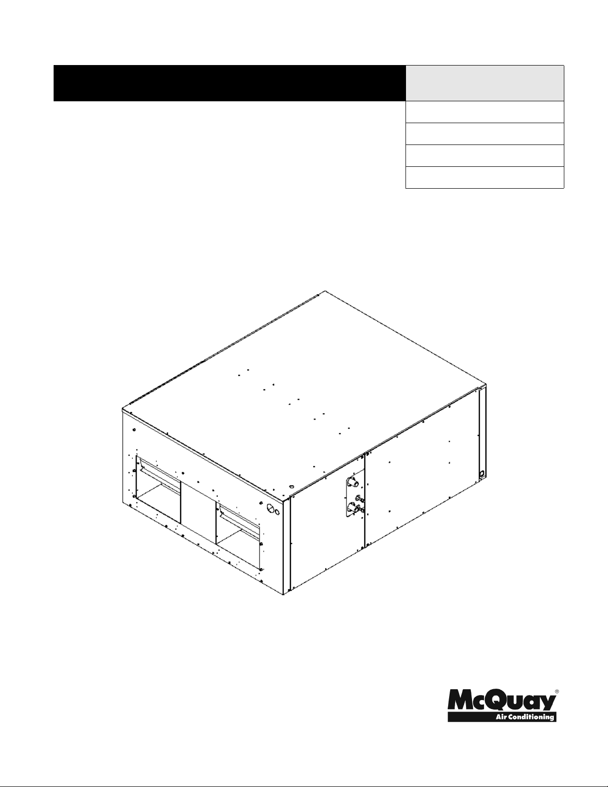
SAH Air Handler
7-1/2 and 10 Tons
Group: Unitary
Part Number: IM-809
Date: August 2005
Supersedes: July 2005
© 2004 McQuay International
IM-809 Page 1
Page 2

Table of Contents
MODEL NOMENCLATURE . . . . . . . . . . . . . . . . . . . . . . . . . 3
INTRODUCTION . . . . . . . . . . . . . . . . . . . . . . . . . . . . . . . . . 4
GENERAL WARNINGS. . . . . . . . . . . . . . . . . . . . . . . . . . . . 5
PRODUCT DESCRIPTION . . . . . . . . . . . . . . . . . . . . . . . . . 6
ORIENTATION . . . . . . . . . . . . . . . . . . . . . . . . . . . . . . . . . . 7
LOCATION . . . . . . . . . . . . . . . . . . . . . . . . . . . . . . . . . . . . . 7
DUCTWORK . . . . . . . . . . . . . . . . . . . . . . . . . . . . . . . . . . . . 7
ELECTRICAL SUPPLY WIRE AND MOP . . . . . . . . . . . . . . 8
CONVERSION TO 460V ELECTRICAL POWER SUPPLY 9
ELECTRICAL CONNECTIONS . . . . . . . . . . . . . . . . . . . . . .10
HEAT KIT INSTALLATION. . . . . . . . . . . . . . . . . . . . . . . . . 11
REFRIGERANT LINES . . . . . . . . . . . . . . . . . . . . . . . . . . . .11
EVAPORATOR COIL TXV . . . . . . . . . . . . . . . . . . . . . . . . . 12
AIRFLOW . . . . . . . . . . . . . . . . . . . . . . . . . . . . . . . . . . . . . .12
BELT TENSION . . . . . . . . . . . . . . . . . . . . . . . . . . . . . . . . .13
MAINTENANCE . . . . . . . . . . . . . . . . . . . . . . . . . . . . . . . . .13
WIRING DIAGRAM . . . . . . . . . . . . . . . . . . . . . . . . . . . . . . .14
"McQuay" is a registered trademark of McQuay International.
© 2004 McQuay International
"Illustrations and information cover the McQuay International products at the time of publication and we reserve the right to make changes in
Page 2 IM-809
design and construction at any time without notice."
Page 3
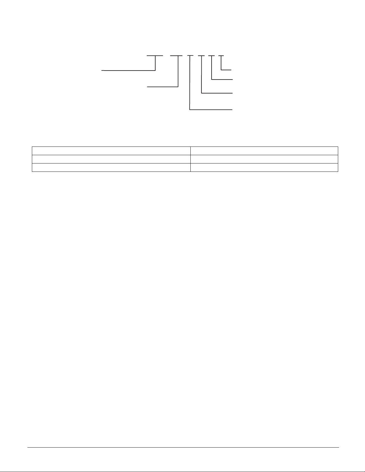
MODEL NOMENCLATURE
M
S
g
*
odel
AH= Split Air Handler Unit
Nominal Capacity (tons)
090 = 7-1/2
120 = 10
SAH090 and 120 units are field-convertible to 460/3/60 voltage.
Table 1: Unit Nameplate Model Number Identifier
Unit Nameplate McQuay Model Number
AR090 SAH090APTY
AR120 SAH120APTY
SAH 090
A
PTY
Future Use
Refrigerant Meterin
T = TXV
Voltage/Phase
P = 208-460/3/60*
Vintage
IM-809 Page 3
Page 4

INTRODUCTION
General Description
These installation instructions cover the indoor installation of
AR series electric split system cooling and heat pump air handlers. See the product catalog for information regarding specifications applicable to your model and accessories.
Receiving Inspection
McQuay products are carefully inspected prior to shipment
and the carrier has assumed responsibility for loss or damage
upon acceptance of the shipment.
Upon receiving your shipment, check all items carefully
against the Bill of Lading. Inspect the unit and/or accessories
for shipping damage as soon as they are received. Immediately file claims for loss or damage, either shipping or concealed, with the shipping company.
Check the unit nameplate to verify the model number and electrical characteristics are correct. In the event an incorrect unit
is shipped, it must be returned to the supplier and must NOT
be installed. The manufacturer disclaims all responsibility for
the installation of incorrectly shipped units.
The SAH evaporator coil contains a high-pressure inert gas
holding charge. Before installing the unit, depress the liquid
line Schrader fitting(s) to verify the integrity of the evaporator
coil. Note that SAH120 units have two (2) liquid line Schrader
valves, both of which should be depressed.
Codes and Regulations
This product is designed and manufactured to permit installation in accordance with National Codes. System design
should, where applicable, follow information presented in
accepted industry guides such as the ASHRAE Handbooks. It
is the installer' s responsibility to install the product in accordance with National Codes and/or prevailing local codes and
regulations. The manufacturer disclaims all responsibility for
equipment installed in violation of any code or regulations.
IMPORTANT
The United States Environmental Protection Agency
(EPA) regulations cover introduction and disposal of
refrigerants in this unit. Failure to follow those
regulations can harm the environment and lead to
substantial fines. Because regulations can change, a
certified technician should perform any work done on
this unit. If you have any questions, please contact the
local office of the EPA.
Important Message to the Owner
Read these instructions carefully and keep them near the product for future reference. Although these instructions are
addressed primarily to the installer, useful maintenance information is included. Have the installer acquaint you with the
operation of the product and periodic maintenance requirements.
Recognize Safety Symbols, Words, and Labels
The following symbols and labels are used throughout this
manual to indicate immediate or potential hazards. It is the
owner's and installer's responsibility to read and comply with
all safety information and instructions accompanying these
symbols. Failure to heed safety information increases the risk
of property damage and/or product damage, serious personal
injury or death. Improper installation, operation or mainte-
nance can void the warranty.
DANGER
Immediate hazards which WILL result in property
damage, product damage, severe personal injury and/
or death.
WARNING
Hazards or unsafe practice CAN result in property
damage, product damage, sever personal injury and/or
death.
CAUTION
Hazards or unsafe practices which CAN result in
property damage, product damage, and/or personal
injury.
Replacement Parts
Replacement parts can be obtained by contacting McQuay at
1
-800-37-PARTS. When contacting McQuay for service or
replacement parts, refer to the model number and serial number of the unit as stamped on the nameplate attached to the
unit.
Important Message to the Installer
This equipment is to be installed by an experienced installation
company and fully trained personnel. Carefully read all
instructions and take into account any special considerations
prior to installing the unit. Give this manual to the owner and
explain its provisions.
Page 4 IM-809
Page 5

GENERAL WARNINGS
WARNING
Verify that all power is disconnected prior to installing
of this equipment. There may be more than one
disconnect servicing this equipment.
WARNING
Before servicing or installing this equipment, the
electrical power to this unit must be in the "OFF"
position. More than one disconnect may exist. Failure
to disconnect power can cause electrical shock, serious
personal injury or death.
WARNING
The unit must have an uninterrupted, unbroken
electrical ground. Failure to properly ground can cause
severe personal injury or death.
WARNING
Installation and service by trained, qualified technicians
only. High pressure and electricity can cause severe
personal injury or death. Observe ALL warnings
contained in this manual and the labels/tags attached to
the equipment.
WARNING
This product is factory shipped for use with a 208-230/
3/60 electrical power supply. However, the air handler
can be reconfigured to operate with a 460/3/60 power
supply provided the conversion noted in the
"Conversion to 460 Electrical Supply" section of this
manual is performed. Failure to observe this warning
can result in personal injury, equipment damage and
fire.
WARNING
This air handler is designed for Upflow or Horizontal Left applications. DO NOT INSTALL IN THE
DOWNFLOW OR HORIZONTAL-RIGHT
ORIENTATION.
WARNING
When installing or servicing, wear protective gloves,
gear and eyeware. Also observe special safety
requirements (hard hats etc.).
CAUTION
To protect the unit when welding close to the painted
surfaces, use a quenching cloth to help prevent
scorching or marring the equipment finish.
IM-809 Page 5
Page 6

PRODUCT DESCRIPTION
When matched with a ACU090 and ACU120 condenser, this
system complies with the minimum efficiency equirements
found in ASHRAE 90.1-1999. See the Product Catalog for
details on these condensers. For other McQuay condenser(s)
that can be matched with this air handler to obtain ASHRAE
90.1-1999 compliance, consult with your local representitive.
Units are intended for use with a room thermostat. This thermostat is not supplied with this equipment. Thermostats that
use 24 VAC control circuitry must be used.
SAH090 SAH120
Net Weight (Lbs.) 375 400
Shipping Weight (Lbs.) 405 430
Refrigerant R22 R22
Blower Wheel (Dia x Width) 11 x 10 11 x 10
Blower Wheel Quantity 2 2
Motor Type Belt Drive
Motor Qty 1 1
Motor (HP) 1 ½ 2 1 ½ 2
Motor (RPM) 1750 1750
Motor Sheave Type Adjustable Variable Pitch
Motor Sheave Diameter (in) 1.9" - 2.9" 2.8" - 3.8"
Blower Wheel Pulley Type Fixed Diameter
Blower Wheel Pulley Dia (in) 5.9 6.5
Evaporator Coil Material Copper Tubes / Al Fins
Face Area (Ft2) 8.9 10.0
Number of Rows 4 4
Suction Line Quantity 1 2
Suction Line Connection (in) * 1 1/8 1 1/8
Liquid Line Quantity 1 2
Liquid Line Connection (in)* 5/8 3/8
Metering Device Thermal Expansion Valve (TXV)
TXV Type Adjustable
TXV Quantity 1 2
* Note: Consult with the condenser specifications for suction and liquid line
sizing.
ELECTRIC HEAT
WARNING
To avoid fire and equipment damage, refer to the "Heat
Kit Installation" section of this manual for the proper
installation procedure.
WARNING
To avoid fire, equipment damage and electric shock, the
electrical characteristics of the air handler, the electric
heat kit, and the building power supply must agree.
This air handler does not have factory-installed electric heat.
Electric heat is available as an accessory. If installing this
option the ONLY heat kits that can be used is the AHKD series
as indicated in Table 2.
Table 2: AHKD Electric Heaters
AHKD Model Number Nominal W
AHKD15-3 15 208-230/3/60 1
AHKD15-4 15 460/3/60 1
AHKD20-3 20 208-230/3/60 2
AHKD20-4 20 460/3/60 2
AHKD30-3 30 208-230/3/60 2
AHKD30-4 30 460/3/60 2
E l e c tr i c a l
Characteristics
Stages
For all supply voltages, use the correction factors in Tables 3
and 4 multiplied by W and (or) temperature rise for corrected
results.
Table 3: W Correction Factors (-3 models).
Supply Voltage 240 230 220 210 208
Correction Factor 1.0 0.92 0.84 0.77 0.75
Table 4: W Correction Factors (-4 models)
Supply Voltage 480 460 440 415 380
Correction Factor 1.0 0.92 0.84 0.75 0.63
The heating mode temperature rise is dependent upon the system airflow, the supply voltage, and the heat kit size (W)
selected. Use Tables 5 and 6 to determine the temperature rise
o
(
F):
Table 5: SAH090 Temperature Rise Table (Degrees F)
Air
Handler
SAH090 15 2800 14 19 19
Heat Kit W CFM
2900 14 18 18
3000 13 18 18
3100 13 17 17
3200 12 17 17
20 2800 19 25 25
2900 18 24 24
3000 18 24 24
3100 17 23 23
3200 17 22 22
30 2800 28 38 38
2900 27 37 37
3000 27 35 35
3100 26 34 34
3200 25 33 33
Table 6: SAH120 Temperature Rise Table (Degrees F)
Air
Handler
SAH120 15 3800 10 14 14
Heat Kit W CFM
3900 10 14 14
4000 10 13 13
4100 10 13 13
4200 9 13 13
20 3800 14 19 19
3900 14 18 18
4000 13 18 18
4100 13 17 17
4200 13 17 17
30 3800 21 28 28
3900 20 27 27
4000 20 27 27
4100 19 26 26
4200 19 25 25
Supply Voltage
208 240 480
Supply Voltage
208 240 480
Page 6 IM-809
Page 7

Note: Tables 5 and 6 are calculated with both stages of
electric heat engaged (2-stage heat systems). For
systems using staged electric heat, divide the temperature rise from the tables by 2 for 1st stage operation.
ORIENTATION
Units can be mounted in the following orientations:
• Upflow
• Horizontal - Left Hand
DO NOT INSTALL THIS AIR HANDLER IN THE HORIZONTAL-RIGHT OR DOWNFLOW ORIENTATION.
LOCATION
DANGER
This unit can distribute carbon monoxide (CO), an
oderless, colorless toxic gas that can cause severe
personal injury or death. The area must be properly
vented and joints must be tight so CO cannot enter duct
work or enclosed space.
WARNING
Units are not weather tight and are designed for indoor
installations only. DO NOT INSTALL OUTDOORS.
DUCTWORK
Units are designed for a complete supply and return ductwork
system. DO NOT OPERATE THIS PRODUCT WITHOUT
BOTH DUCTWORK SYSTEMS ATTACHED.
For proper system performance, size the ductwork systems to
accommodate 375-425 CFM per ton of cooling with a static
pressure not to exceed 0.5" W.C. Inadequate ductwork that
restricts airflow can result in improper cooling performance
and compressor failure. Construct ductwork in a manner that
limits restrictions and maintains suitable air velocity. Seal
ductwork to the unit in a manner that will prevent leakage.
Supply Ductwork Flanges. The supply ductwork flanges
are shipped loose and must be field installed.
further details. Dimensions are approximately 40" x 13-1/8"
Figure 1. Supply Ductwork Flanges
See Figure 1 for
Units are suitable for installation in multiple locations including:
• Overhead (Attic/Mezzanine, etc)
• Closet/Mechanical Room
When installing this air handler, give careful consideration to
minimizing the length of refrigerant tubing. Do not install the
air handler in a location either above or below the condenser
that violates the instructions provided with the condenser.
Allow a minimum of 36" in front of the unit for service clearance. Allow sufficient clearance to remove heater elements for
service or replacement when heat kits are utilized in the application.
When installing in an area directly over a finished ceiling
(such as an attic) an emergency drain pan is required directly
under the unit. See local and state codes for additional requirements.
When installing this unit in an area that may become wet, elevate the unit with a sturdy, non-porous material.
In installations that may lead to physical damage (warehouse,
industrial sites, etc.), install a protective barrier to prevent
equipment damage.
Return Ductwork. DO NOT TERMINATE THE RETURN
DUCTWORK IN AN AREA WHICH CAN INTRODUCE
TOXIC FUMES/ODORS INTO THE DUCTWORK. Introduce the return ductwork
into the air handler bottom. The cabi-
net dimensions are 48" x 24".
Return Air Filters. This unit is factory equipped with disposable return air filters. To provide optimum performance frequent filter replacement is advised. See Table 7 for the
factory-installed filter sizes:
Table 7: Factory-Installed Filter Sizes
Model Filter Size (in.) Qty.
SAH090 16 x 20 x 2 4
SAH120
16 x 20 x 2
20 x 20 x 2
2
2
IM-809 Page 7
Page 8

ELECTRICAL SUPPLY WIRE
AND MOP
WARNING
Before servicing or installing this equipment, the
electrical power to this unit must be in the "OFF" position.
More than one disconnect may exist. Failure to observe
this warning may result in an electrical shock that can
cause personnel injury or death.
WARNING
The unit must have an uninterrupted, unbroken electrical
ground. Failure to properly ground can cause severe personal injury or death.
Voltage Balance. The supply voltage shall be unbalance
(phase to phase) within 2%. To calculate the percentage of
voltage unbalance, use the following formula:
Percentage
Voltage = 100 x
Unbalanace
Max Voltage Deviation From Average
Average Voltage
Example
L1 - L2 = 220 V
L2 - L3 = 216 V
L1 - L3 = 213 V
Avg. Voltage = (220+216+213) / 3
= 649 / 3
= 216
Max. Deviation from Avg. = 220 - 216 = 4
The unit must have an uninterrupted, unbroken electrical ground.
The electrical ground circuit may consist of an appropriately
sized electrical wire connecting the ground lug in the unit control box wire to the building electrical service panel. Other
methods of grounding are permitted if performed in accordance with the National Electric Code (NEC)/American
National Standards Institute (ANSI)/National Fire Protection
Association (NFPA) 70 and local/state codes. In Canada, electrical grounding is to be in accordance with the Canadian Electric Code CSA C22.1. Failure to observe this warning can
result in electrical shock that can cause serious personal injury
or death.
WARNING
To avoid the risk of fire or equipment damage, use only
copper conductors.
WARNING
This product is capable of using either 208-230/3/60 or
460/3/60 supply voltage. Units are factory shipped for use
with 208-230/3/60 voltage. Installations using 460/3/60
require modification to the motor and transformer
electrical circuits. Refer to the "Conversion to 460V
Power Supply" section of this manual. Do not operate this
appliance using a 460V power supply unless this
modification has been made. Failure to observe this
warning may result in personal injury, equipment damage
and fire.
Inspection of the Building Electrical Service. This unit
is designed for 3-phase operation. DO NOT OPERATE ON A
SINGLE PHASE POWER SUPPLY. Measure the power supply to the unit. The supply voltage must be in agreement with
the unit nameplate power requirements and within the range
shown in Table 8.
Table 8: Minimum and Maximum Supply Voltage
Nominal
208-230 187 253
460 414 506
Minimum Supply
Vol tag e
Maximum Supply
Vol tag e
% Voltage Unbalance = 100 x (4 / 216)
= 400 / 216
= 1.8%
Determine Wire Size. The selection of the appropriate supply wire size is important for proper operation of the equipment. The following are important considerations:
• The wire size is adequately sized to carry the Minimum Circuit
Ampacity (MCA). Refer to the NEC (USA) or CSA (Canada) for
wire sizing. The unit MCA for the airhandler and the optional
electric heat kit can be found on the equipment nameplate and
Table 9.
Table 9: Minimum Circuit Ampacity
Air Handler Voltage Heat Kit MCA
SAH090 208-230 NONE 6.5
AHKD15-3 48.6
AHKD20-3 63.0
AHKD30-3 91.9
460 NONE 3.3
AHKD15-4 24.3
AHKD20-4 31.5
AHKD30-4 46.0
SAH120 208-230 NONE 7.5
AHKD15-3 49.4
AHKD20-3 63.8
AHKD30-3 92.7
460 NONE 3.8
AHKD15-4 24.7
AHKD20-4 31.9
AHKD30-4 46.4
Page 8 IM-809
Page 9

• The wire size is appropriately sized to allow for no more than a
2% voltage drop from the building breaker/fuse panel to the unit.
• Refer to the latest edition of the National Electric Code or in Canada the Canadian Electric Code when determining the correct wire
size. Table 10 shows the current carrying capabilities for copper
o
conductors rated at 75
C with a 2% voltage drop
Table 10: Maximum Allowable Length in Feet to Limit Voltage
Drop to 2%*
Wire Size
(AWG)
14 75 50 37 NR NR NR NR NR
12 118795947NRNRNRNR
10 188 125 95 75 63 54 NR NR
8 301 201 150 120 100 86 75 68
6 471 314 235 188 157 134 118 110
Based on NEC 1996*
10 15 20 25 30 35 40 45
Min. Circuit Ampacity (MCA)
Maximum Overcurrent Protection (MOP)
Every installation must include an NEC (USA) or CEC (Canada) approved overcurrent protection device. Also check with
local or state codes for any special regional requirements.
This protection can be in the form of fusing or HACR style circuit breakers. Table 11 can be used as a guide for selecting the
MAXIMUM overcurrent device. This information is also
stated on the equipment nameplate. Note: Fuses or circuit
breakers are to be sized larger than the equipment MCA but
not to exceed the MOP listed below.
Table 11: Maximum Overcurrent Protection
Air Handler Heat Kit MOP
SAH090 NONE 15
AHKD15-3 60
AHKD20-3 70
AHKD30-3 100
NONE 15
AHKD15-4 30
AHKD20-4 35
AHKD30-4 50
SAH120 NONE 15
AHKD15-3 60
AHKD20-3 70
AHKD30-3 100
NONE 15
AHKD15-4 30
AHKD20-4 35
AHKD30-4 50
CONVERSION TO 460V ELECTRICAL
POWER SUPPLY
Transformer. The transformer is multi-rated with a 208V,
240V, or 480V primary input.. To change from the factory setting of 230V to 460V applications, remove the Orange colored
wire attached to the 240 terminal on the primary side of the
transformer. Install this wire on the transformer terminal
marked 480. Similarly, move the Orange wire from 240 to 208
for 208V applications.
Figure 2. Transformer Conversion
Motor Conversion. This conversion requires access to the
motor electrical junction box that is located on the motor endplate on the side opposite from the shaft. Use the following
diagrams when performing this procedure.
Figure 3. Motor Conversion
SAH090
SAH120
WARNING
This product is capable of using either 208- 230/3/60 or
460/3/60 supply voltage. this air handler is factory
shipped for use with 208-230/3/60 voltage. Installations
using 460/3/60 requiring modification to the motor and
transformer electrical circuits. Do not operate this
appliance using a 460V power supply unless this
modification has been made. Failure to observe this
warning may result in personal injury, equipment damage
and fire.
Note: Perform this conversion in an area that will permit
easy accessibility.
IM-809 Page 9
Page 10

ELECTRICAL CONNECTIONS
Supply Voltage. A single point supply voltage termination is
provided in the air handler control box (non-heat kit models)
or heat kit control box (heat kit models). This termination is
common to both the air handler, and heat kit. The wire is to be
sized in accordance with the "Electrical Wire and MOP" section of this manual.
Supply Voltage - Non-Heat Kit Models. Route supply
wire through conduit from the service disconnect box to the
unit. The air handler is equipped with a knockout suitable for
¾" conduit. Figure 4 illustrates the supply voltage hook-up.
Figure 4. Supply Voltage Hook-up (Non Heat Kit Models)
Low Voltage. The 24V control voltage connects the air handler to the room thermostat and condenser. For systems using
staged electric heat, the thermostat is to have W1 and W2
functions. Use copper conductors and a minimum of 18AWG
for low voltage wiring. A provision on the cabinet side to
accept the low voltage wiring is provided. See Figure 6 for
typical low voltage connections
Figure 6. Low Voltage Connections
No Heat - Single Stage Cooling where R… Red,
G… Green, BL…. Blue Note white wire and brown
wire are not used and are to be taped.
Supply Voltage - Heat Kit Models. When a heat kit is
used, the system uses a single point wiring hook-up. Route the
supply wire through conduit from the service disconnect box
to the heat kit. The heat kit is equipped with a knockout suitable for ½" or ¾" conduit dependent on the kW. Install the supply voltage on the terminal block located in the heat kit control
box.
The heat kit is factory-equipped with the supply and low voltage wires for the air handler. The low voltage connection from
the heat kit is provided through a multi-pin plug that connects
to a mating plug in the air handler. The high voltage connections are to be made at the air handler contactor. These wires
are to be routed through the pipe nipples supplied with the heat
kit as shown in Figure 5:
Figure 5. Supply Voltage Hook-up (Heat Kit Models)
Single Stage Heat - Single Stage Cooling where R…
Red, W… White, G… Green, BL…. Blue Note brown
wire is not used and is to be taped.
Two Stage Heat – Single Stage Cooling - where
R… Red, W… White, BR… Brown, G… Green,
BL…. Blue
Page 10 IM-809
Page 11

HEAT KIT INSTALLATION
Inspect for Shipping Damage. The heat kit is an optional
accessory that is shipped separately from the air handler.
Inspect the heat kit for damage and report any damage to the
carrier. Do not install this accessory if it is determined that the
integrity has been compromised by freight damage.
Check the Nameplate. From the heat kit nameplate check
the following:
• The model number agrees with the approved models (see
the "Electric Heat" section of this manual).
• The correct size (kW)
• Electric characteristics, voltage and phase agree with the
building electrical supply.
General Guidelines. The following guidelines must be followed when installing heat kits:
• When installed in a garage, the elements must be at least
18 above the floor.
• If this appliance is installed in an enclosed area such as a
garage or utility room with any carbon monoxide (CO)
producing appliance (i.e. automobile, furnace, water-heater
etc.), verify that the area is properly ventilated.
• A means of strain relief and conductor protection must be
provided at the supply wire entrance.
• This appliance must be installed following the ANSI/
NFPA70 (National Electrical Code) and other applicable
codes. If in doubt, contact the local authority having jurisdiction.
• Use copper conductors only
• Some localities require the installer be licensed. Contact
the local authority if in doubt.
Failure to follow these instructions can cause fire, explosion, electrical shock, property damage, personal injury, or
death.
DANGER
This unit can distribute carbon monoxide (CO), an
oderless, colorless toxic gas that can cause severe
personal injury or death. The area must be properly
vented and joints must be tight so CO cannot enter duct
work or enclosed space.
Attaching the Heat Kit. The heat kit attaches directly to the
top panel (when viewed in the upflow position) of the air handler. Do not screw the heat kit into the duct flanges (Figure 7).
Figure 7. Attaching The Heat Kit
The wires from the heat kit are to be routed through the pipe
nipple into the air handler electrical compartment. See the
"Electrical Connection" section of this manual for wiring
details.
REFRIGERANT LINES
CAUTION
To protect the unit when welding close to the painted
surfaces, use a quenching cloth to prevent scorching or
marring the equipment finish.
Preparing the Tubing. All cut ends are to be round, burr
free and cleaned. Failure to follow this practice can result in
refrigerant leaks. The equipment suction line(s) are spun
closed and require pipe cutters to cut off the closed end. The
liquid lines have a Schrader valve soldered on the end. Unsweat the Schrader valve(s) and clean the end of these tubes.
Post Brazing. Quench all welded joints with water or a wet
rag.
IM-809 Page 11
Page 12

Piping Size. For the correct size tubing, follow the specification for the condenser/heat pump.
The SAH090 coil is circuited to accept a single suction and liquid line. The SAH120 evaporator coil has (2) suction lines and
(2) liquid lines. When using a single condenser, such as the
ACU120 with the SAH120, it is necessary to manifold the suction lines into a single connection. Similarly, the liquid lines of
the SAH120 are to be manifolded when matched with a single
condenser/heat pump. The manifolds must be sized to accept
the suction and liquid line diameters prescribed within the
condenser Installation Manual. See Figure 8 for additional
details.
Figure 8. Liquid and Suction Lines with a Single
Condensor/Heat Pump
SAH090
EVAPORATOR COIL TXV
Note: The Thermal Expansion Valve (TXV) Bulb is not
permanently connected to the suction line from the
factory. After the suction and liquid line tubing is
brazed in the field, the TXV bulb must be attached
to the suction line(s) inside the cabinet at the 10 or 2
o'clock position and insulated. This location will be
different for vertical or horizontal orientation.
Always locate the TXV bulb on the top of the suction tube at 10 or 2 o'clock.
For most installations, no adjustment to the TXV setting is
required. However, if the measured superheat is less than 80 or
greater than 200, an adjustment is required. The adjustment
stem is at the base of the valve (opposite the diaphragm) under
a flair nut.
To increase the superheat (when measured at the condenser
base valve), turn the stem clockwise (in). To decrease the
superheat, turn the stem out (counterclockwise). Use a ¼"
refrigeration wrench for this function.
Refer to the condensing unit / heat pump installation instructions for the charging method.
AIRFLOW
The blower uses a belt drive motor that has an adjustable
sheave. The factory setting for the SAH090 is 2 turns open.
The SAH120 is 3 turns open.
SAH120 SINGLE OUTDOOR UNIT
Multiple Condensers. The AR120 can accept (2) condensers/heat pumps. See Figure 9 when using two condensers.
Figure 9. Liquid and Suction Lines with Multiple
Condensers/Heat Pumps
SAH120 TWO OUTDOOR UNITS
To increase the airflow:
• Remove the blower belt
• Loosen the set screw as shown in Figure 10, rotate the other half
clockwise (screw in).
• Tighten the set screw
• Re-install the belt
Figure 10. Airflow Adjustment
To decrease the airflow perform the same steps, but rotate the
sheave counterclockwise (screw out).
Page 12 IM-809
Page 13

Table 12 can be used as guide for system airflow:
Table 12: System Airflow
SAH090
Static
Pressure
.1 4264 3930 3633 3273
.2 3996 3705 3325 2998
.3 3731 3379 3002 2517
.4 3445 3066 2613
.5 3113 2662
12345
SAH120
Static
Pressure
.1 5193 5037 4790 4097 4097
.2 5012 4873 4603 3842 3842
.3 4852 4675 4393 3589 3589
.4 4687 4484 4172 3295 3073
.5 4501 4268 3939 2922 2610
.6 4293 4041 3673 2642
.7 4073 3742 3347
.8 3807 3485 2962
.9 3540 3117
12345
Sheave Turns Open
Sheave Turns Open
BELT TENSION
The belt tension is to be checked at the time of installation and
after a "run in" period of about 24 hours. To perform the measurement, use a "Belt Tension Gauge" that is available from
most belt manufacturers. The force required to deflect the belt
1/8" (at the midpoint) should be between 3 ½ and 5 pounds.
MAINTENANCE
Routine maintenance is essential for the proper operation of
this air handler. A few preseason checks can help avoid costly
repairs and down time.
1. Check and change air filters as needed
2. Check, adjust or replace belts and check sheaves for proper
operation.
3. Clean the evaporator coil and check for duct leaks.
4.
Check for proper charge and (or) for refrigerant le
aks.
IM-809 Page 13
Page 14

WIRING DIAGRAM
THERMOSTAT
RBR
W1
W
C
GRW2
BL
G
SUPPLY VOLTAGE
L2 L1
1
4
G
L3
52
6
3
BL
CONTACTOR
SUPPLY VOLTAGE
L2
L3
L3
L2
L1
CONTACTOR
T3
EVAP.
MOTOR
T1
T2
B
B
B
O
FACTORY WIRED FOR 240V
SEE NOTE FOR MOTOR
CONNECTIONS
BL
COLOR CODE
B
BL
BR
G
O
R
W
BLACK
BLUE
BROWN
GREEN
ORANGE
RED
WHITE
L1
G
C
B
BL
PRIMARY
208V
240V
480V CDM
BL
SECONDARY
24V
TRANSFORMER
WIRING CODE
FACTORY WIRING
HIGH VOLTAGE
LOW VOLTAGE
FEILD WIRING
HIGH VOLTAGE
LOW VOLTAGE
G
W2
R
W1
RELAY
(SEQUENCER)
CDM
EVAP.
MOTOR
1
2
FACTORY WIRED
FOR 240V
SEE NOTE FOR
MOTOR
CONNECTIONS
R
R
PRIMARY
240V
480V
208V
TRANSFORMER
SECONDARY
24V
BLOWER
BL
RELAY
4
CONTACTOR
24V
BLOWER
R
RELAY
5
6
PLUG
W2
W1
G
C
R
NOTES:
1. ALL REPLACEMENT WIRES MUST BE
SAME GAUGE AND TYPE.
2. TO CHANGE VOLTAGE FROM 240V TO
208V, MOVE WIRE FROM 240V TAP TO
208V TAP AT TRANSFORMER PRIMARY.
3. TO CONVERT VOLTAGE FROM 240V TO
480V:
a. MOVE WIRE FROM 240V TAP TO
480V TAP AT TRANSFORMER PRIMARY.
b. IDENTIFY MODEL (AR120 OR AR090)
AND REWIRE MOTOR FROM LOW
VOLTAGE (240V) TO HIGH VOLTAGE
(480V) ACCORDING TO INSTRUCTIONS.
A.O. SMITH MOTOR
SAH120 MOTOR
HIGH VOLTAGE
(480V)
7
4
8
5
9
6
14
INSULATE
15
INSULATE
16
INSULATE
LOW VOLTAGE
(240V)
1
L1
2
L2
3
L3
14
4
15
5
16
6
1
7
8
9
L1
2
L2
3
L3
SAH090 MOTOR
HIGH VOLTAGE
(480V)
T4
T7
T5
T8
T6
T9
P4
INSULATE
P5
INSULATE
P6
INSULATE
LOW VOLTAGE
(240V)
T1
L1
T2
L2
T3
L3
T4
T5
T6
T7
P4
P5
P6
T1
T8
T9
L1
T2
L2
T3
L3
Page 14 IM-809
Page 15

This document contains the most current product information as of this printing. For the most up-to-date
product information, please go to www.mcquay.com.
www.mcquay.com • 800-432-1342
 Loading...