

Page 1
Installation, Operation & Maintenance Manual
Refrigerant Recovery Unit, Model RRU999
IOMM RRU999
Group: Refrigerant
Effective: December 2000
Supersedes: New
© 1999 McQuay International
Page 2

Table of Contents
Specifications...........................................................................................................................3
Product Description.................................................................................................................4
Shipping Contents ...................................................................................................................5
Operating Procedures.............................................................................................................6
Calibration Procedure .............................................................................................................9
Changing Compressor Oil.....................................................................................................10
Display Sequence..................................................................................................................12
Electrical Parts Breakdown..................................................................................................13
Replacement Parts List........................................................................................................14
Troubleshooting.....................................................................................................................15
"McQuay" is a registered trademark of McQuay International
"Illustrations cover the general appearance of McQuay International products at the time of publication and we reserve the right to make
changes in design and construction at anytime without notice."
2 IOMM RRU999
1997 McQuay International
Page 3

Specifications
Electrical Power Requirements
Recovery Main Components : 460 VAC, 60 Hz, 7.5-Hp, 3-Phase, 20-Ampe res
For Controls : 115 VAC, 50/60 Hz, 1-Phase, 20-Amperes
Dimensions (approximate): 54 in. high x 40 in. wide x 40 in. deep
Weight: 400-lbs. (550-lbs shipping)
575 VAC, 60 Hz, 7.5-Hp, 3-Phase, 20-Amperes
NOTICE
McQuay International urges that all HVAC servicers working on McQuay equipment or any
manufacturer’s products, make every effort to eliminate, if possible, or vigorously reduce the
emission of CFC, HCFC, and HFC refrigerants to the atmosphere resulting from installation,
operation, routine maintenance, or major service of this equipment. Always act in a
responsible manner to conserve refrigerants for continued use even when acceptable
alternatives are available. Conservation and emission reduction can be accomplished by
following recommended service and safety procedures.
WARNING
To avoid injury or death due to inhalation of, or skin exposure to refrigerant, closely follow
all safety procedures described in the Material Safety Data Sheet for the refrigerant and to
all labels on refrigerant containers. Certain procedures common to refrigeration system
service may expose personnel to liquid or vaporous refrigerant.
IOMM RRU999 3
Page 4
Product Description
McQuay’s RRU999 recovery system provides automated recovery of most positive-pressure
refrigerants and blends.
The unit consists of a 7.5-hp compressor with a suction accumulator, oil separator, dual high capacity
air-cooled condensers, microprocessor control system, and actuated valving system. Unit
connections are 1¼ in. male pipe with isolation valves.
After the hoses are connected and purged or evacuated, the RRU999 starts automated recovery by
letting the refrigerant migrate from the A/C system to the recovery tank. It then draws vapor off the
recovery tank, heats it via compression, and injects it back into the A/C system high side, thus
creating a pressure differential before commencing liquid transfer.
When a pressure transducer determines that pressure differential is below 20 psig and the liquid
sensor determines that liquid transfer has been completed, the RRU999 will switch from liquid
push/pull mode to vapor recovery. The recovery unit then begins removing vapor from both sides of
A/C system. Vapor refrigerant is first cleansed by the 96 cubic inch inlet drier, then travels through
coalescent oil separator, then through a suction accumulator, through a crankcase pressure regulator,
then finally into the compressor where refrigerant is then compressed. Discharged hot gas from the
compressor is then sent through an oil separator where oil is extracted from the hot gas and returned
to the compressor. The refrigerant is then condensed by the dual air-cooled condensers and sent to
the recovery tank.
The RRU999 can be programmed to stop transfer at 0 psi or 15 in. Hg vacuum. This transfer stops
when a pressure transducer indicates the A/C system reaches the programmed pressure. The unit
then confirms the vacuum level by monitoring pressure for two minutes. Should pressure in the A/C
system rise, the RRU999 energizes again to achieve A/C system vacuum.
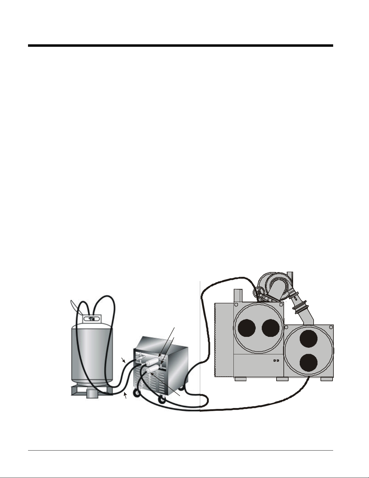
Figure 1, RRU999 Connections
1-1/4” REC OVERY
C YL IND ER PORT S
A/C SYSTEM
S ID E
VAPOR
T ANK
SID E
LIQUID
H OSE
VAPO R
HOSE
L IQ UID
D RIERS
1-1/4” PORT:
EV APORAT OR
1-1/4” PORT:
C OND ENSE R
4 IOMM RRU999
Page 5
Shipping Contents
Furnished with RRU999 are:
• 100-ft. 3 phase-VAC power cord
• 100-ft. 120-VAC power cord
• Two 96 cubic inch drier shells
• Four filter cores
Note: Please follow the recommended procedures outlined in this manual for regular
changing of compressor oil and coalescent oil filter. Before every recovery job install new
drier cores.
Peak Performance:
To get the highest performance from your RRU999 unit, we recommend that you connect to 1¼ in.
evaporator and condenser ports on the chiller or A/C system and to recovery cylinders with 1¼ in.
ports whenever possible.
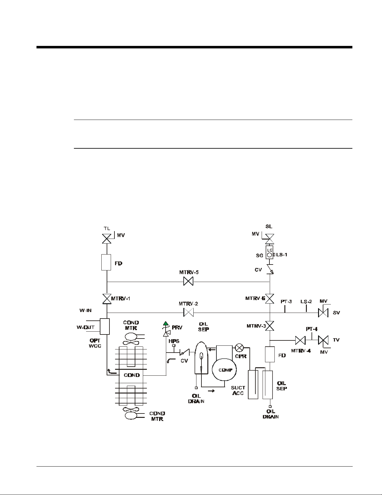
Figure 2, Process and Identification Schematic
IOMM RRU999 5
Page 6

Operating Procedures
:To ensure your safety as well as others, before attempting to recover an A/C, refrigeration or
chiller system, proper and thorough preparation must take place.
• Make sure you have a recovery cylinder with a minimum 1¼ in. male flare vapor port and a
minimum 1¼ in. male flare liquid port. This tank or series of tanks have to be able to hold the
entire charge.
• Reminder: The refrigerant full weight is 80% of water capacity weight determined as follows:
Maximum allowable gross weight = 80% of water capacity weight + cylinder tare weight.
• In addition, a suitable scale should be used to weigh the tanks in case the RRU999 needs to be
shut down to prevent overfilling tanks. If a scale is not available, the tanks can be equipped at
the time of purchase with a float switch that will work with the RRU999’s microprocessor
control circuit.
• Finally, the recovery cylinder or cylinders must be pulled into a 29 in. vacuum before recovery
commences. Failure to follow these above stated procedures will decrease the likelihood of the
RRU999 performing at its highest possible effectiveness.
1. Turn the chiller, refrigeration or A/C system off and make sure that the system cannot restart.
2. Connect the 100-ft 3-phase power cord to a proper size breaker or fused disconnect and plug it
into the RRU999’s control box. Connect the 100-ft 120-VAC 1-phase power cord for controls.
Connect at this time, if equipped, with the 80% safety shut off float cable.
3. At this point, the display lights up indicating the unit has power and prompting you to press
“Start”.
An additional feature can be accessed at this time, by pressing the “M” key. This display
will show you the total compressor run time as well as give you a historical maintenance
schedule. In addition, at every 10 hours of cumulative operating run time for the compressor,
an automatic message will appear each time you start the RRU999 until maintenance is
performed. After changing oil, then press the “Enter” key which records that maintenance
has been performed. A message will then not appear until the next 10 hours of compressor
run time is accumulated. The system will retain a log of each maintenance event recorded.
4. The RRU999 then asks you to “Select Refrigerant” being recovered. Scroll to the desired
refrigerant using the “M V” keys then press “Enter”.
5. The RRU999 then prompts you to check selection by displaying “Selected Refrigerant R___,
Is This Correct? Enter = Yes, Canc = No”. The RRU999 then prompts you to select the
vapor transfer shutdown pressure with “USE M V to select 0 PSI or 15 Hg Shutdown”. Select
desired shutdown pressure, then press “ENTER”.
6. The RRU999 then asks you to “Connect all Refrigerant Hoses” then press “Enter”. Connect
two hoses to the RRU999’s recovery side liquid and vapor ports and to liquid and vapor ports on
the recovery cylinder. Connect other two hoses and 96 cubic inch drier shells to system side
ports on the RRU999 and to the chiller evaporator and condenser or A/C system.
7. Open vapor and liquid access valves on A/C system being recovered then press “Enter”.
8. “Open system vapor and liquid hand valves on the RRU999 recovery unit” then press “Enter”.
9. “Open recovery vapor and liquid hand valves on the RRU999 recovery unit” then press
“Enter”.
CAUTION
6 IOMM RRU999
Page 7

Note: If the recovery hoses have isolation valves, open them now.
10. The RRU999 then asks you to “Purge Both Refrigerant Lines at the Recovery Tank” then
press “Enter”.
11. Next “open vapor and liquid hand valves on recovery tank” then press “Enter”.
12. The RRU999 then displays “Liquid Transfer!” and displays the A/C system and recovery tank
pressures.
The RRU999 now begins automated recovery while
continuously displaying the A/C system and recovery tank pressures.
Note: The RRU999 is equipped with a coalescent oil separator, designed to remove oil
from the dirty recovered refrigerant. During the recovery periodically drain the oil from this
separator into a suitable container, failure to drain this separator will allow contaminated oil
to be passed through the system and will remain in the recovered refrigerant.
13. Once pressure between the cooling system and recovery tank are within 20-psi of each other
and a liquid sensor indicates that all liquid from the liquid transfer has been removed, the unit
switches to vapor recovery, displaying “Vapor Recovery in Process” and continues to display
the A/C system and recovery tank pressures.
If the RRU999 does not switch to vapor recovery and you are absolutely sure that all of the
liquid has been removed, it may be because lines to the recovery tank or to the cooling
system are restricted. In this case, a bypass feature can be accessed that forces the unit to
begin vapor recovery. To perform this task, press the enter key two times in a row during
the liquid recovery mode and vapor recovery will commence.
It is absolutely imperative that all liquid has been transferred before using this override
feature. Failure to do so may result in liquid slugging to the compressor and causing major
damage.
14. When a 15 in. vacuum has been achieved in the A/C system, the unit compressor shuts off and
the display reads “Vapor Recovery 2 Minute Wait State” and displays the time remaining.
At this point, the microprocessor continues to monitor A/C system pressure. Should
pressure rise, the RRU999 restarts to again achieve a 15 in. vacuum.
15. Then the display will read “Vapor Recovery Finished!” Press “Enter”.
Upon pressing “Enter”, the RRU999 prompts you to perform the following valve
manipulations 16-22:
16. “Close access valves on A/C system being recovered” and then press ”Enter”.
17. “Close both hand valves on the RRU999 unit A/C System Side” and press “Enter”.
18. The RRU999 compressor then restarts and begins to force remaining liquid in the RRU999 as
well as liquid in hose into the recovery tank. Displaying “Liquid Refrigerant Clearing in
Process”.
19. “Close both liquid and vapor hand valves on recovery tank” and press “Enter”.
20. The RRU999 then begins evacuating the recovery tank vapor hose, displaying “Hose
Evacuation in Process”.
21. When the hose evacuation is complete the unit displays “Close both Liquid and Vapor Tank
Hand Valves on RRU999 Unit”, then press “Enter”.
22. Finally, the unit displays “System Recovery Completed! Disconnect all Hoses and Power”.
At this time, close all four refrigerant hose isolation valves located on the ends of the
refrigerant hoses connected from the RRU999 to the recovery tank.
IOMM RRU999 7
Page 8

There will still be a small residual amount of refrigerant in the RRU999. This amount must be
removed if you want to change to a different type of refrigerant. An explanation on how to remove
this residual amount of refrigerant is described in the next paragraph.
Removing Remaining Residual Refrigerant
a. Connect the center tap of a manifold set to a suitable vacuum pump inlet and the discharge side
of the pump to a 50 lb. evacuated recovery cylinder. Connect the low and high side of the
manifold set to the ¼ in. compressor suction and discharge access ports located on the side of
the RRU999 unit.
b. Open valve on the 50 lb. recovery tank and turn on the vacuum pump. Open the low and high
side manifold valves and wait until a 29 in. vacuum has been achieved on your manifold gauge.
c. Close both manifold valves, shut down the vacuum pump and close the recovery tank valve.
If you intend to use the RRU999 on a different type of refrigerant, make sure to change the
compressor oil and disposable driers.
Changing Replaceable Cores
Make sure you replace filter cores after each recovery job. Simply unscrew bolts on the drier shells
and replace the cores in the filter assembly.
The driers and compressor lubricant are available from McQuay.
8 IOMM RRU999
Page 9

Calibration Procedure
Pressure Transducer Calibration Procedure
The RRU999 unit is equipped with a sensitive pressure transducer which needs to be calibrated prior
to running the RRU999. This will take into account the variations in atmospheric pressure at various
altitudes and locations.
McQuay recommends that this calibration procedure be performed if any of the following events
occur:
a. Any time a new pressure transducer is installed on the unit.
b. Any time that the unit is moved to a substantially different altitude or is exposed to significantly
different atmospheric pressure.
c. Any time that the pressure readings appear to be questionable or there is any reason to doubt the
accuracy of the transducer readings.
Calibration Procedure Steps:
1. At power up, the RRU999 recovery unit will display:
“RRU999 Commercial Recovery Unit”
“Has Power ( Press Start)”
2. At this screen you must press “CANCEL” twice within 5 seconds to enter the calibration
mode. The display will then show the following:
“Open Pressure Transducers to Atmosphere” (Then press “Enter” key)
3. Now, with no hoses connected, open the liquid and vapor system and recovery tank valves on
the RRU999 to the atmosphere and press “Enter”.
4. The screen will then display the following message:
“System Pressure XX PSI”
“Press Enter To Calibrate This Transducer”
The system is displaying the raw, uncalibrated reading from the transducer. If you press
“Enter”, it will calculate a calibration value and store it in the computer’s nonvolatile
memory. If you press “Cancel”, a new calibration factor will not be calculated.
5. It will then display the following message:
“Recovery Tank Pressure xx HG”
“Press Enter to Calibrate this Transducer”
The system is once again displaying the raw, uncalibrated reading from the transducer.
Once you press “Enter”, it will calculate a calibration value for this transducer and store it in
memory. If you press “Cancel”, a new calibration factor will not be calculated. It will then
display the following message and be ready for operation:
“RRU999 Commercial Recovery Unit”
“Has Power ( Press Start)”
IOMM RRU999 9
Page 10

Changing Compressor Oil
The compressor’s charge of Polyol Ester fluid should be regularly replaced with an identical fluid or,
at a minimum, after these events:
1. After a maximum of 10 hours of run time.
2. When changing recovery jobs that involve different refrigerants.
3. After recovering a system with a burnt out compressor.
To remove and change the oil in the compressor and the oil separator:
When changing oil, it is highly recommended that the same type of oil being used with the
refrigerant being recovered be used in the RRU999 compressor. This will help ensure that
cross contamination does not occur.
a. Make sure the RRU999 unit has no refrigerant in its internal parts.
b. Connect a manifold set to dry nitrogen and to the suction and discharge service ¼ in. access
ports located on the side of the RRU999.
c. Connect another ¼ in. hose to the access fitting on the bottom of the RRU999 oil separator
fitting and the other end to a suitable disposable oil container.
d. Gradually allow dry nitrogen to go into the discharge port on the RRU999 unit until all oil has
been forced out of the oil separator. Note : 10 to 15 PSI will be more than adequate.
WARNING
e. Remove oil plug from rear of compressor located just below heater junction box. Drain into a
suitable disposable oil container.
f. Gradually allow dry nitrogen to go into the suction port on the RRU999 unit until all oil has been
forced out of the compressor.
g. To add new oil to the RRU999 compressor, connect a vacuum pump to the ¼ in. access port on
the suction side of the compressor. Pull down into a minimum 29 in. vacuum.
h. Connect other hose to the ¼ in. access port on the top rear of the compressor and into the new
oil container. Note : Fill compressor with exactly 50 oz. of oil.
i. Connect the other hose to the ¼ in. access port on the bottom of the oil separator and into the
same new oil container. Note : Fill the separator with exactly 16 oz. of oil.
j. Once this procedure is finished, remove all hoses and pull the entire RRU999 into a 29 in.
vacuum. Dispose of old oil properly.
Note: After approximately 20 hours of continuous recovery replace coalescent filter in the
oil separator. This procedure can be accomplished by removing the oil separator side
panel, unscrewing bolts on the oil separator body and replacing the coalescent filter per
instructions given with the filter.
WARNING
Failure to follow above procedures for recharging oil in the compressor with the exact
amount of oil may result in major damage to the compressor.
10 IOMM RRU999
Page 11

Figure 3, Block Wiring Diagram
Y
A2
L3
A2
L2
L1
A1
BR O Y
2
BK
1
BK
T3
T 2
O
T1
A1
BR
R
3+
SSR
4-
FAN MOTOR
BK
L
G
BR Y
G+5 G + 12
SUPPLY
POWER
TRI VOLT DC
B
W
N
20 W
CPU
PRES
PT 3
MOTOR
COMPRESSOR
+ 12
BK YL
G
RD
+5
SYSTEM
PR ES
PT 4
TANK
F ULL
TANK
PT 5
80 %
9
765
432
BBB
3
1
5-8
3
412
1-4
Common
#1 ACTUATOR
TO AC T.
T O ACT.
W
W5B
8
6
7
4
WW B B
BB
Common
#5 ACTUATOR
#3 ACTUATOR
#4 ACTUATOR
#2 ACTUATOR
W
TB-2
W
12
5v
99
1010
Comm onComm on
8
675
#6 ACTUATOR
#7 ACTUATOR
FULL
TANK
80%
TANK
SYSTEM
PRESSURE
PRESSURE
W
B
SINGLE
PHASE
120 VOLT
G
CIRCUIT
BREAKER
G
FUSE
BR
Y O
HEATER
CRANK CASE
BR
OY
BK
SWITCH
PRESSURE
FAN
MOTOR
5
BELI MO
FAN
MOTOR
R
L
R
L
R
L
1
ACT UAT OR
4
BELIM O
BELIM O
AC TUATO R
2
1
R
B
2
VBEL IM O
R6L
ACTUATO R
3
BELIM O
BELIM O
ACTUATO R ACT UAT OR
R
L
R
L
ACTUATO R
3 PHASE
IOMM RRU999 11
Page 12

Display Sequence
High Pressure Refrigerant Recovery Only
RECOVERY UNIT HAS POWER (PRESS START)
IS THIS CORRECT? (ENTER = YES, CANC = NO)
USE TO SELECT 0 PSI OR 15 HG SHUTDOWN
OPEN VAPOR & LIQUID ACCESS VALVES ON
A/C SYSTEM BEING RECOVERED (PRESS ENTER)
OPEN SYSTEM VAPOR & LIQUID HAND VALVES
OPEN RECOVERY VAPOR & LIQUID HAND VALVES
RRU999 RECOVERY UNIT
SELECT REFRIGERANT WITH KEYS
R___ (PRESS ENTER)
SELECTED REFRIGERANT R___
0 PSI SELECTED
CONNECT ALL REFRIGERANT HOSES
ON RECOVERY UNIT (PRESS ENTER)
ON RECOVERY UNIT (PRESS ENTER)
(PRESS ENTER)
VAPOR RECOVERY SYSTEM - - PSI
IN PROCESS RECOVERY CYLINDER - - PSI
VAPOR RECOVERY 2 MINUTE
WAIT STATE 0:00
VAPOR RECOVERY FINISHED!
(PRESS ENTER)
CLOSE ACCESS VALVES ON A/C SYSTEM BEING
RECOVERED (PRESS ENTER)
CLOSE BOTH HAND VALVES ON
UNIT A/C SYSTEM SIDE (PRESS ENTER)
LIQUID REFRIGERANT CLEARING IN PROCESS
CLOSE BOTH LIQUID & VAPOR HAND VALVES
ON RECOVERY TANK (PRESS ENTER)
0:00
PURGE BOTH REFRIGERANT LINES AT THE
RECOVERY TANK (PRESS ENTER)
OPEN VAPOR & LIQUID HAND VALVES ON
RECOVERY TANK (PRESS ENTER)
CHANGING VALVE SEQUENCE
90 SECOND WAIT 1:30
LIQUID TRANSFER! SYSTEM LIQUID - - PSI
IN PROCESS RECOVERY CYLINDER - - PSI
CHANGING VALVE SEQUENCE
90 SECOND WAIT 1:30
HOSE EVACUATION IN PROCESS
CLOSE BOTH LIQUID & VAPOR TANK HAND
VALVE ON UNIT (PRESS ENTER)
SYSTEM RECOVERY COMPLETED!
DISCONNECT ALL HOSES & POWER
0:00
12 IOMM RRU999
Page 13

Electrical Parts Breakdown
1. Compressor Motor:
7.5Hp, 460VAC, 50/60Hz, 3Ph
7.5Hp, 575VAC, 50/60Hz, 3 Ph for 575 Model
2. Condenser Fan Motor - 115/230 VAC 60Hz
3. High Pressure Switch
4. (2) Pressure Transducer
5. (6) Actuator Ball Valve Assembly - 120 VAC 50/60 Hz 133 in-lbs 150s
6. Male Inlet - 50A, 480VAC, 3PH, 4W or 600VAC For 575 Model
7. Male Inlet -15A,125V, 1PH, 3W GRD
8. Terminal Block
9. Power Supply - 20W, 115V, 1A / 230VAC, 0.6A
10. Contactor-120V 50/60Hz 10Hp 600 VAC - MAX 30A open
11. CPU Mother Board Assembly
13. Display Board Assembly
14. Keypad
18. Circuit Breakers- 20 Amp, 250 VAC, 28 VDC
19. Float Connector
IOMM RRU999 13
Page 14

Replacement Parts List
Reference Number Part Number Description
1..........................EVA182.................Motor Actuator
2..........................RVA150.................Actuated Ball Valve Assembly
3..........................XPT287.................Pressure Transducer
4..........................RVC055.................Check Valve
5.........................ROS055.................Vapor Comp Oil Separator
6..........................RPR008.................Crankcase Pressure Regulator
7..........................RSA011.................Suction Accumulator
8..........................MFR004.................Unit Frame
9.........................EMO237.................Compressor Drive Motor
9.........................EMO575.................Compressor Drive Motor
10.........................HMB184.................Motor Slide Base
11 .........................HPY294.................Motor Drive Pulley
12.........................HBU009.................Motor Drive Pulley Bushing
13.........................HBT261.................Motor Drive Belts
14.........................HPY004.................Compressor Pulley
15.........................RCP755.................Vapor Recovery Compressor
16.........................EMO112.................Cond Fan Motor
17.........................HFB125.................Cond Fan Blade
19........................RCC014.................Condenser Coil
20.........................RSL004.................Liquid Level Sensor
21.........................RSG001.................Liquid Chamber Sight Glass
23.........................RVC055.................Liquid Check Valve
24.........................XPT287.................Pressure Transducer
25.........................RVA150.................Hand Ball Valves Tank and System
26.........................XKP006.................6 Button Keypad
27.........................XPC210.................Display Board A-2 40X2 LCD
28.........................XCA034.................Ribbon Cable 34 Pin Assembly
29........................XPC101B................Mother Board B-1 Allvac Stuffing
32..........................EMI200..................Male Inlet 230/480
32..........................EMI459..................Male Inlet 600V
33..........................EMI115..................Male Inlet 115V
34.........................XPS200.................Power Supply (Electronics)
35.........................XTL210.................10 Position Terminal Strip
38.........................XRY150.................Solid State Relay
39.........................ECP004.................Contactor
14 IOMM RRU999
Page 15

Troubleshooting
To avoid injury or death due to inhalation of, or skin exposure to refrigerant, closely follow
all safety procedures described in the Material Safety Data Sheet for the refrigerant and to
all labels on refrigerant containers. Certain procedures common to the refrigeration system
service may expose personnel to liquid or vaporous refrigerant.
Troubleshooting Procedures
If functional difficulties are experienced and the preceding maintenance checks do not resolve the
problem, refer to the following troubleshooting chart for assistance.
Troubleshooting Guide
The following guide is provided to assist in analyzing problems that could occur.
• Symptom: Describes what is happening;
• Cause: Suggests possible sources;
• Solution: Describes what must be done.
Symptom Cause Solution
EVAC will not switch from
liquid mode to vapor mode
when transferring high
pressure refrigerant.
Slow liquid transfer. Restriction in flow. Replace restrictive fittings and hoses with appropriate
Pressure differential between
system and recovery tank
becomes too high - greater
than 50 psig.
Unit will not pump down to a
15 in. vacuum on final vapor
refrigerant recovery.
Oil separator float is stuck
open and feeding refrigerant
back to suction side of
compressor.
EVAC running high head
pressure back to recovery
tank.
Automatic actuator valves do
not function.
WARNING
Still have liquid in system. When the pressure differential between system and
receiving tank is less than 15 psig, and all liquid has
been removed, unit will automatically switch from liquid
to vapor mode.
Possible malfunction. If unit does not automatically switch to vapor mode,
make sure that all liquid has been transferred and that
no liquid is in the sight glass. Press ENTER key 2 times
in a row. This will manually force EVAC into vapor
mode.
size to expedite transfer.
Restrictions in recovery line. Restriction in liquid recovery lines or tank. Tank needs
to have a 1¼ in. ID valve. Many tanks do not have 1¼
in. valves. McQuay provides tanks fitted with properly
sized valves for this purpose.
Pressure transducer not
properly calibrated.
Restriction in hoses going to
tank.
Capacity of recovery tank is
too small or tank is overfilled.
High concentration of
noncondensibles.
Loss of power to valves. Make sure LED’s on A-4 circuit board are working. If
Verify that displayed pressure is equal to gauge
pressure. If they are different, please follow the
calibration procedures enclosed to calibrate the
pressure transducer.
Drain compressor oil separator.
Replace with appropriately sized hoses and fittings.
Run water over tank or add secondary water cooled
condenser on liquid return line going to recovery tank.
McQuay has available secondary water cooled and air
cooled condensers.
Replace with appropriately sized tanks.
Remove noncondensibles.
LED signal is present at A-4 board, check to verify that
24 VAC is being supplied to actuators. If 24 VAC is
not present, replace transformer.
IOMM RRU999 15
Page 16

16 IOMM RRU999
Page 17

Page 18

Post Office Box 2510, Staunton, Virginia 24402-2510 • (800) 432-1342 • www.mcquay.com
 Loading...