

Page 1

MicroTech®
RMS Sensor Kit
General Description
The RMS Sensor Kit provides a zone temperature sensor and outside-air temperature-sensor for the
RMS Panel.
Inspection
Verify that all required parts have been included:
Quantity Item Description
Installation & Maintenance Data
IM 501
: Controls
Group
Part Number
: August 1997
Date
552192Y-03
:
1 Outside Air Temperature Sensor
1 Zone Temperature Sensor
1 Gray PVC Mounting Track
1 Printed Circuit Board
1 Ribbon Cable (10 Conductor)
2 #8 Sheet Metal Screws
Installation
Printed Circuit Board
Fasten the PVC mounting track to the lower right corner of the panel as shown in Figure 1. Use the
two #8 sheet metal screws provided.
Attach the PC board to the PVC track so that the ribbon connector is adjacent to the microprocessor.
Place one end of the board in the track, and apply a slight downward pressure at the other to snap the
board in place.
Connect the ribbon cable as indicated (the connectors have a polarizing nose to assure correct
position). A downward pressure on each connector engages the locking tabs. Check to be sure that the
connector is locked by pressing the locking tabs between your thumb and forefinger.
Zone Temperature Sensor
Follow the installation instructions in Bulletin No. IM 529-3, “MicroTech Room Temperature
Sensors,” which is included with the sensor. Note that Table 1 of IM 529 indicates that three
conductors are required for the sensor included in this kit (Standard sensor #1); however, for this
application, only two conductors are required.
Wire the sensor as shown in Figure 2. Use a twisted, shielded pair cable (Belden 8762 or equivalent).
© 1997 McQuay International
Page 2
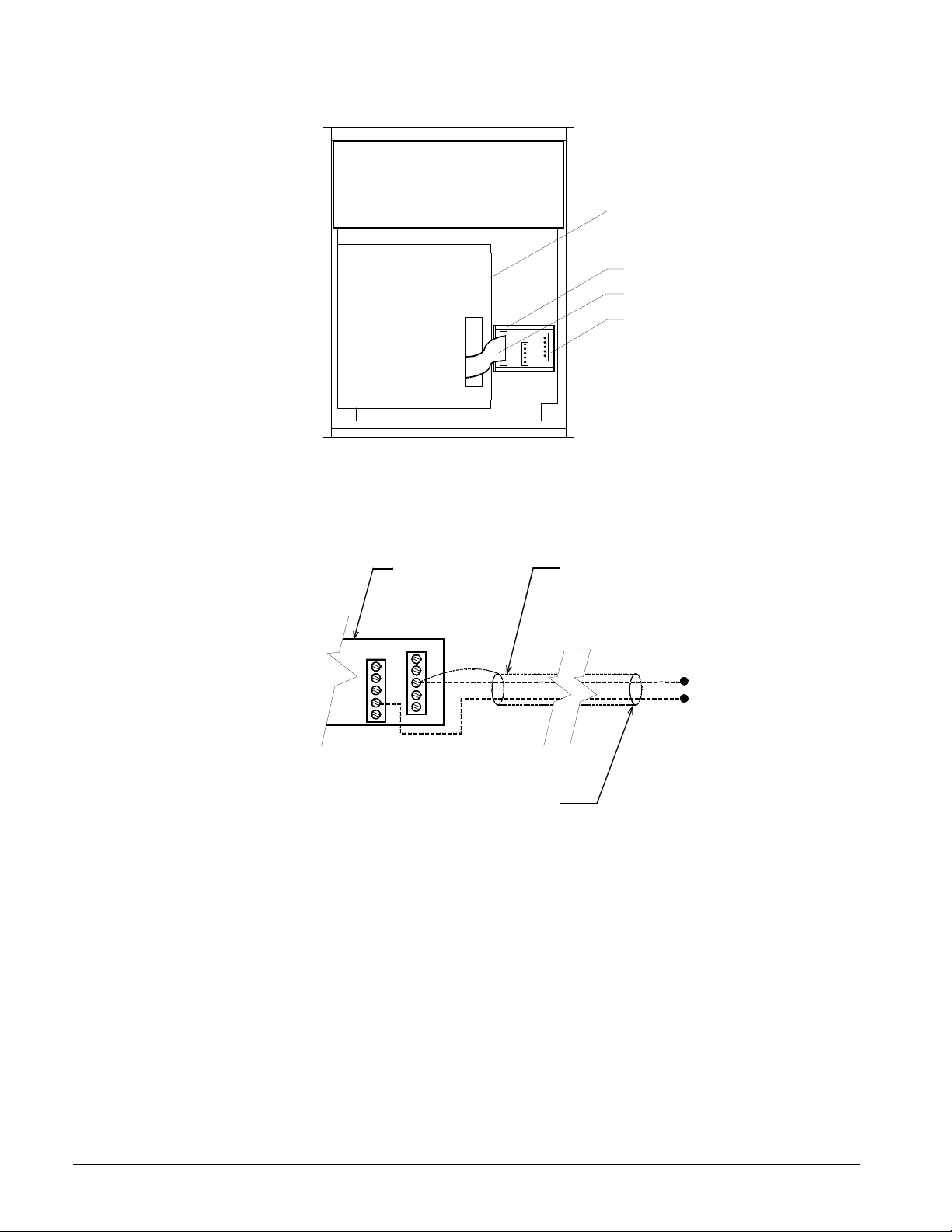
Figure 1. RMS Panel
ANALOG INPUTS
Figure 2. Zone Temperature Sensor Connection
Microprocessor
Mounting Track
Ribbon Cable
PC Board
a0065
PC Board
3
4
Strip back and tape shield at
sensor to prevent contact.
Belden Cable 8762 or Equivelant
Maximum Cable Length = 500 ft.
4-20 mA or
0-5 Vdc
a0068
Outside Air Temperature Sensor
Locate the outdoor-air temperature-sensor in a shaded area away from devices such as exhaust fans.
The preferred location is under a roof soffit on a north-facing wall.
Position the junction box horizontally as indicated in Figure 3 with the sensor shield on either the left
or right. The shield can be rotated by hand so that the angled end always faces down. Do not mount
the sensor in the vertical position.
Wire the sensor as shown in Figure 4. Use a twisted, shielded pair cable (Belden 8762 or equivalent).
Do not cut or shorten the 8-foot wire leads provided with the sensor (the lead length prevents
moisture from entering the sensor element). Using the insulation displacement type connectors
provided, terminate the wires at the sensor by inserting the unstripped wires into the connector and
pressing the red button into the connector body with a pliers.
2 IM 501
Page 3

Figure 3. Outdoor Air Temperature Sensor Mounting
Correct mounting position
Do not mount sensor
in the veritcal position.
Figure 4. Outdoor Air Temperature Sensor Connection
Shield
a0048
PC Board
3
4
Strip back and tape shield at
sensor to prevent contact.
Belden Cable 8762 or Equivelant
Maximum Cable Length = 500 ft.
Use crimp connectors provided.
Do not
use wire nuts
Outside Air Sensor
.
a0069
IM 501 3
Page 4

External Signals
If the RMS panel has special software, 2 external 4-20 mA or 0-5 Vdc signals can be connected to the
controller. Figure 5 shows one external signal wired to analog input 2 at PC board terminals 7 and 8.
Similarly, an external signal wired to analog input 3 would be connected at terminals 9 and 10. Use a
twisted, shielded pair cable (Belden 8762 or equivalent) for each input signal.
!
CAUTION
Ground loop current hazard. Can cause equipment damage.
The external signal must be isolated from any ground other than the MicroTech controller
chassis ground (PC board terminal 5). If it is not, ground loop currents could occur which
could damage the MicroTech controller. If the device or system providing the external signal
is connected to a ground other than the MicroTech controller chassis, be sure that it is
providing an isolated output, or condition the output with a signal isolator.
Figure 5. External Signal Connection
PC Board
3
4
Strip back and tape shield at
sensor to prevent contact.
Belden Cable 8762 or Equivelant
Maximum Cable Length = 500 ft.
4-20 mA or
0-5 Vdc
a0068
13600 Industrial Park Boulevard, PO Box 1551, Minneapolis, MN 55440 USA (612) 553-5330
 Loading...