

Page 1

BULLETIN NO. IM 150-4
INSTALLATION AND
MAINTENANCE DATA
FORM NO. 308972Y REV. A
MODELS RHP & RHQ
FEBRUARY, 1981
AIR COOLED CONDENSING UNIT
3/4,
1,
1
1/2,
2,,
3,
5,
7
1/22
and
10
HP
Page 2

Page 3
INSPECTION
When the equipment is received,
all items should be carefully checked
against the bill of lading to be sure all crates and cartons have
been received.
when received.
carrier immediately and a claim should be filed.
All units should be carefully inspected for damage
If any damage is found,
it should be reported to the
The unit nameplate
should be checked to make sure that the voltage agrees with the power
supply available.
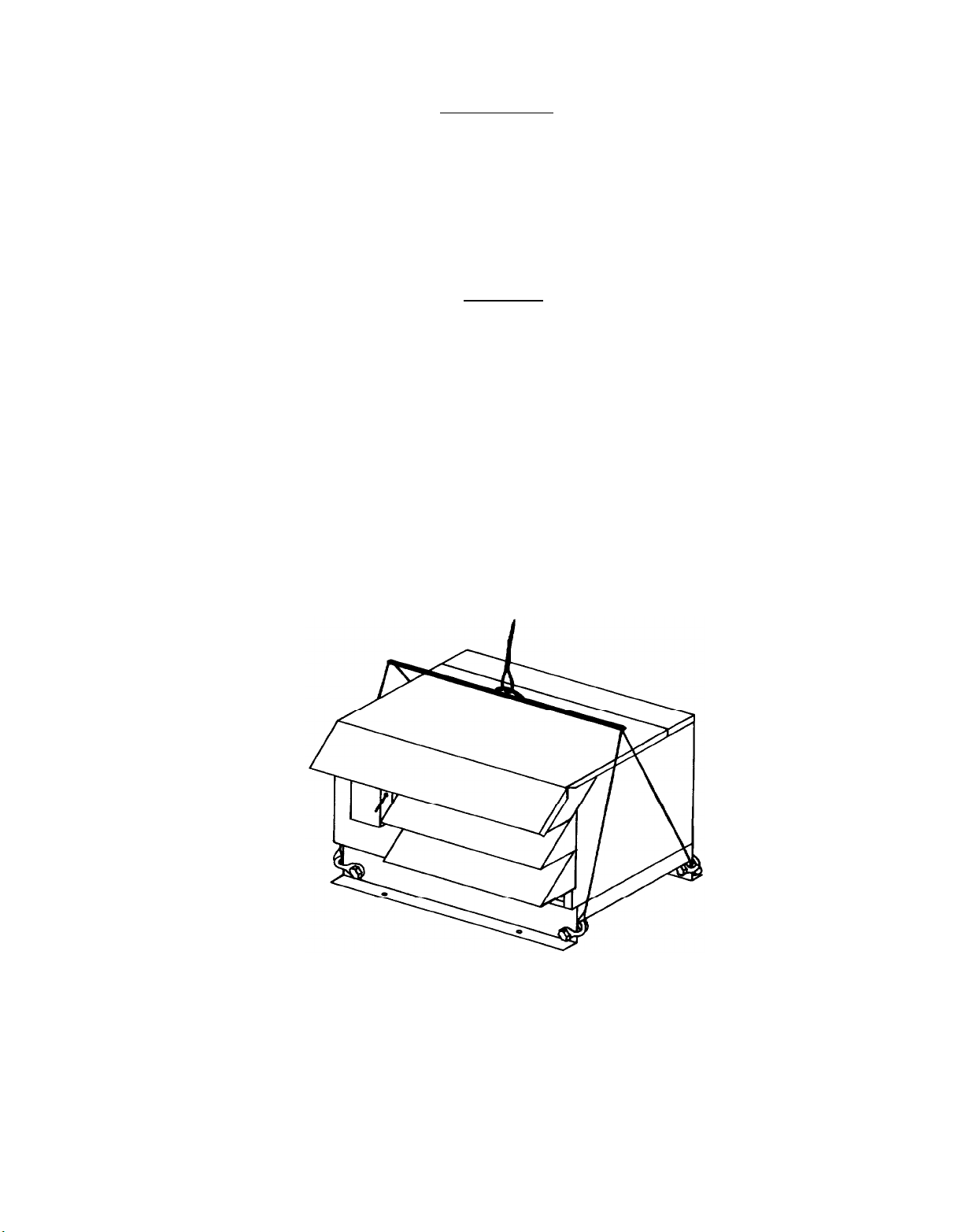
RIGGING
Remove nuts from bolts that hold unit to skid.
from skid.
protect the cabinet.
steel pipe,
points.
Rig unit as shown in Figure 1.
On 007 through 020 units, use two lengths of
inserted through holes in the unit base, as lifting
See Table 1 for unit weights.
This will free unit
Use a spreader bar to
FIGURE 1
UNIT RIGGING
Page 3
Page 4

INSTALLATION
General
Commercial equipment of this type is intended for installation by
qualified refrigeration mechanics.
As a condition of the warranty,
the check tests and startup procedure must be performed by qualified
personnel and must be properly reported on the form provided with
each unit.
Arrangements for service should be made prior to in-
stallation as it is not included in the warranty or the selling
price.
Unit Location
Units are designed for outdoor application and may be mounted on a
roof or concrete slab (ground level installation).
Roof mounted
units should be installed level on steel channels or an I-beam frame
to support the unit above the roof.
lators is recommended.
the weight of the unit.
The roof must be strong enough to support
See Table 1 for unit weights.
Use of vibration pads or iso-
Concrete
slabs used for unit mounting should be installed level and be prop-
erly supported to prevent settling.
A one piece concrete slab with
footings extended below the frost line is recommended.
The condenser coil side of the unit should be located no closer than
four feet from any wall or other obstruction to provide sufficient
clearance for air entrance.
be provided on the discharge side of the unit.
work to the coil inlet or fan outlet.
At least four feet of clearance should
Do not attach duct-
Care should be taken to avoid
air recirculation conditions that can be caused by sight screening,
walls, etc.
Also keep unit fan discharge away from any building air
intakes.
TABLE 1
l 1
l/8
on
050B-H
PHYSICAL DATA
CONNECTIONS
SHIPPING
Page
4
Page 5

Sound and Vibration
Units should be installed away from occupied spaces and above or outside of utility areas,
transmission of sound and vibration to occupied spaces.
corridors and auxiliary spaces to reduce the
The refrig-
erant piping should be flexible enough to prevent the transmission
of noise and vibration from the unit into the building.
If the re-
frigerant lines are to be suspended from the structure of the building, isolation hangers should be used to prevent the transmission of
vibration.
Where piping passes through a wall, it is advisable to
pack fiberglass and sealing compound around the lines to minimize
vibration and retain flexibility in the lines.
FIELD WIRING
Make the
on the unit,
codes and ordinances.
ation must not exceed
supply
All wiring must be done in accordance with applicable
power connection to the fused safety switch supplied
Size conductors using Table
+lO%
of the nameplate value.
on three-phase units must not exceed 2%.
TABLE 2
TOTAL
23Ol
1P
10.9
10.6
1 1.2
23.4
20.0
26.6
UNIT
A
MPS
5.1
5.9
5.9
6.7
6.5
7.8
7.8
7.8
1 I
,
I
-
_ _
I
23.3
208-
:
!30/3P(
-___
17.2
15.9
14.9
23.4
23.2
21 .6
35.1
34.1
35.3
57.1
58.0
_
46.0
L
RHP/RHQ
r
:ONDENSINC
UNIT SIZE
007&M
OlOB-L
0100-M
015B-L
015B-M
OZOB-L
OZOB-M
02OB-H
030B-L
030B-M
030B-H
050B-L
050B-M
05OB-H
075B-L
075B-M
075B-H
1 OOB-L
1008&l
1 OOB-H
NOTE:
1. Based on condenser fan motor FLA at 208 volts.
2. Based on 125% of compressor RATED LOAD AMPS plus 100%
of FLA for all other motors. Select conductors based on NEC
310-16 or
3. Use only time delay dual element fuses.
4. Based on maximum allowable unit cooler motor amps as shown
in table 9.
T
I
2081
1P
7.8 7.7
9.0 7.4
8.9 7.6
9.1 6.5
9.0 6.8
12.4
13.1
_
-
_ 22.9
-
_ 29.1
-
_ 35.2
_ _
- -
_ _
_ _
_ _
-
310-18.
ELECTRICAL RATINGS
MINIMUM CIRCUIT AMPS MINIMUM CIRCUIT AMPS
FOR UNITS WITHOUT
5.7
6.7
6.7
7.9
7.7
9.3
9.3
9.3
.J
.9
(2) ADE
4601
3P
+
_
_ 16.6
_ 16.4
_ 16.8
_ 16.7
_ 27.6
-
_
_ _
-
_
_ _
22.6
22.6
19.4
35.1
35.6
27.9
_
] - 1 -
13.5
28.2
T CIRCUIT
208- I
230/38(l)
20.4
18.8
17.5
28.2
27.9
25.9
41
40.4
41
69.2
70.3
55.3
FOR UNITS WITH
ROST
2081
YTZ-
IP
16.3
27.8
_
_
_
-
-
-
-
-
-
CIRCUI
2.
Voltage vari-
Phase unbalance
MAXIMUM
2301
I
45
35
50
FUSE
4
SI2
;
_
_
T
I
2)
(41
T(
T
,
4601
ZOO81
1P lP
3P
_
15 15
_
15 15
-
15 15
_
15 15
-
15 15
25 20
25 20
_ 20
-
_ 45
-
_
-
-
_ 50
_
_ 60
_ _
37.6
_
37.6
32.9
-
50.1
_ _
50.6
- -
,
42.9
15 _
15
15
15
15
15
15 _
15
30
25
25
45
45 _
40 _
60 35
60 35
60 30
100 50
100 60
90 45
I
-
-
-
_
-
-
-
-
-
-
Page 5
Page 6

The unit is designed to operate with a pumpdown cycle, therefore a
solenoid valve must be installed in the liquid line (see Figure 2).
Make sure that the system is wired so that the pumpdown cycle is initiated if power to the unit cooler fan motors is disconnected.
Diagrams 1and 2 show typical control wiring for air and electric
defrost applications respectively.
SEAsommm
Diagram 15 shows field wiring of the Seasonmiser system.
must have a pump down solenoid valve in the liquid line.
FIELD
WIRING (RHQ
ONLY)
All units
The primary
of the Class II transformer is connected in parallel with the pump
down solenoid valve.
in series with the sensor and heat motor assembly.
pressure control is required,
The transformer secondary (24 VAC) is connected
If a differential
it is connected in parallel with the
subcooling sensor.
DIAGRAM I
DIAGRAM 2
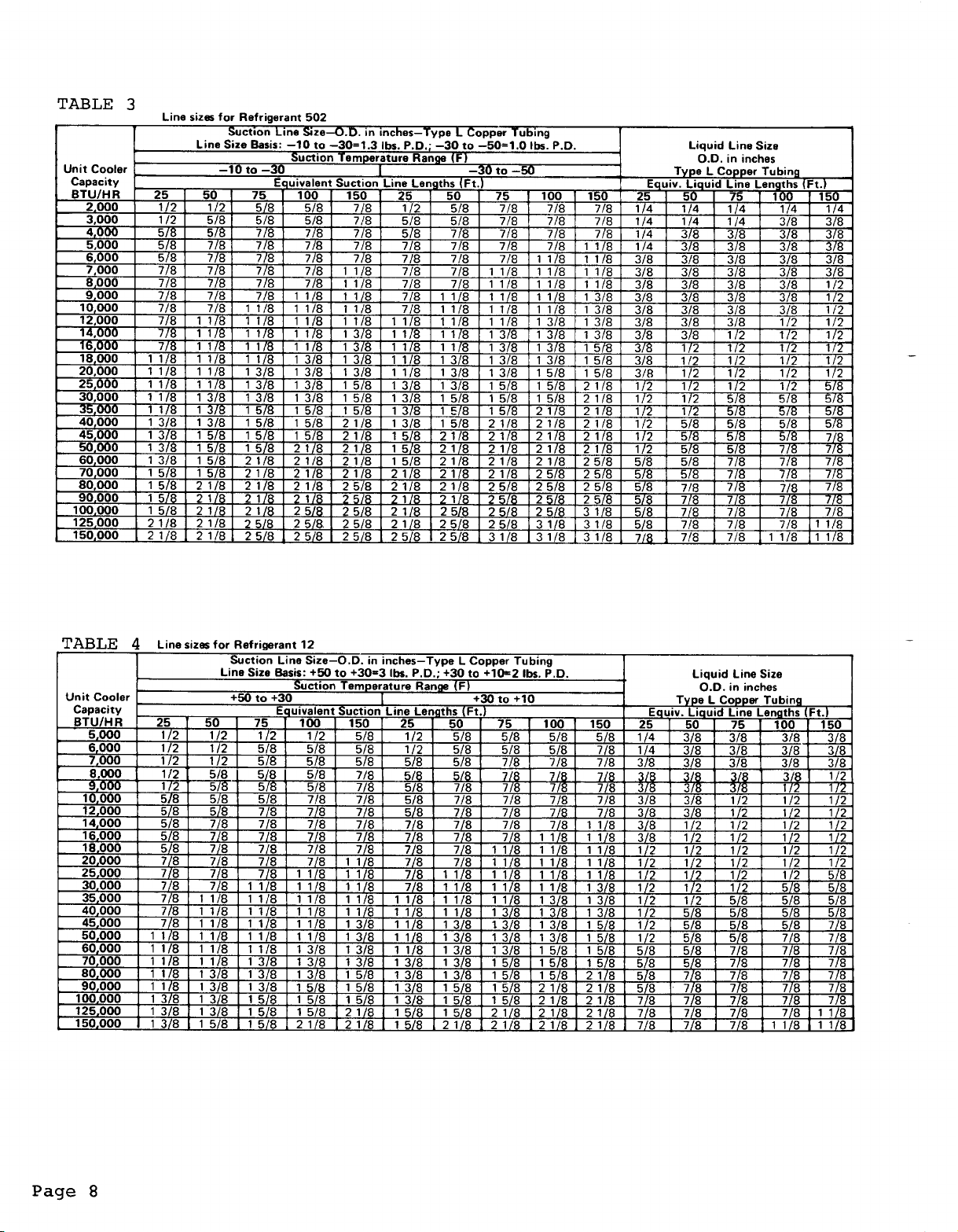
PIPING
Install piping according to standard accepted refrigeration practice.
See Figure 2 for typical refrigerant piping. The following recom-
mendations should be adhered to.
See Tables 3,4 and 5 for recommended liquid and suction line
1.
sizing.
2.
Use only refrigeration grade copper tubing.
3.
Soft solder joints are not acceptable.
Pass dry nitrogen through lines while brazing.
4.
Do not leave dehydrated piping or components open to the atmos-
5.
phere any longer than is absolutely necessary.
Use a P-trap at the base of suction risers greater than 3
6.
to 4ft.in
height to improve oil return.
Page 6
Page 7

7.
8.
9
_ .
10.
Slope suction line
l/2"
per 10 ft.
in direction of flow to improve
oil return.
Support piping with hangers to prevent transmission of vibration
to the building.
If not furnished with condensing unit, install a filter-drier
and a sight glass in the liquid line.
A solenoid valve must be installed in the liquid line because
the condensing unit is designed to operate with a pump down cycle.
FIGURE
1
2
3
4 Thermostatic Expansion Valve
5 Liquid Line
6 Suction Line, Pitched Toward Compressor
7
NOTE: FILTER-DRIER AND SIGHT GLASS MAY BE
2
LEGEND
Filter-Drier
Solenoid Valve
Sight-Glass/Moisture indicator
Drain Line, Heat Trace for Low Temperature
FURNISHED WITH CONDENSING UNIT.
TYPICAL REFRIGERANT PIPING
SEASONMISER PIPING
(RHQ
ONLY)
To maximize the energy-saving potential of the Seasonmiser system,
keep tubing runs as short as possible and insulate the liquid line
all the way to the cold zone.
desired to prevent sweating.
prevent suction gas at the compressor from rising above
The suction line may be insulated if
In any case,
care must be taken to
65OF
under
any condition.
Locate the subcooling sensor (and differential pressure switch where
required) at the point where the liquid line enters the refrigerated
space.
The location should be outside of the refrigerated space.
The subcooling sensor should be within 12" of the entry point.
Pump down solenoid valves and heat exchangers (where used) should be
downstream of the subcooling sensor.
with the evaporator shortens sensor life.
Making the sensor pump down
Heat exchangers upstream
of the sensor can allow the formation of flash gas upstream of the
heat exchanger.
The subcooling sensor is assembled with low melting point solder.
It should be installed using flare connections provided.
Brazing
or soldering will damage the sensor.
The differential pressure control should have the pressure tap
labelled liquid connected to the liquid line and the tap labelled
suction connected to the suction line.
Page 7
Page 8
Page 9

Page 10

TABLE 6 CONDENSING UNIT CHARGE(LBS.)
AMBIENT TEMPERATURE F
RHPIRHQ
0070-M
OlOB-L
01OB-M
015B-L
015B-M
02OB-L
02OB-M
020B-H
03OB-L
030B-M
03OB-H
05OB-L
05oB-M
OBOB-H
075B-L
075B-M
075B-H
lOOB-L
lOOB-M
IOOB-H
10 0
1
4.7
4.5
4.7
5.6
5.9
5.6
5.9 6.0 6.1
5.4
10.4
10.9
9.9
18.2 I 18.7
34.6 35.5 36.1 37.0
36.5 37.4
33.2 33.9 34.6
4.8 4.9 5.0
I
4.6
4.8
1
5.7 7
610
1
5.7
5.5 5.6
I 10.5
11.1 11.3
10.1
-10
1
4.7
419
2::
1
Tmp5.8
1
10.7
10.3
I
19.0 I 19.5 1
38.0 38.9
-20
lower
.I
I
1
4.8
5.0
5.9
6.2
5.9
6.2
5.7
11 .o
11.6
10.6
35.5
%I
TABLE 7
LGTH.
OF
LIQ. LINE O.D. OF LIQUID LINE
(FT.)
in
20 0.34
30 0.51
40
50
60
70 1.19
a0
90
100
l/4
0.17 0.47
0.68
0.85 2.35
1
.02
1.36 3.76 6.96 11.20
1.53 4.23 7.88 12.60
1.70 4.70 8.70 14.00
CHARGING AND INITIAL STARTUP
1.
Make sure all electrical
2.
The compressor oil level
ter of the sight glass.
3.
Make sure the compressor
They should be tightened
under the hold down nuts
Check all system controls and adjust if necessary.
4.
in pressure of the low pressure switch for the lowest ambient in
which the condensing unit will be operated, using Table 8.
the cut-out pressure low enough to avoid short cycling.
Make sure compressor suction and discharge valves are back-seated.
5.
Attach charging line to charging port on liquid line valve and
6.
front-seat the valve.
Turn on electrical power to the condensing unit and the unit
7.
cooler(s).
8.
Open the valve on the refrigerant cylinder and begin charging
liquid refrigerant into the system.
when the low pressure switch closes.
total system charge, as calculated,
9.
When the correct charge has been added back-seat the liquid line
valve.
Page 10
LIQUID LINE CHARGE
3/a
0.94
1.41
1
2.82
3.29
I
1
.88
connections are tight.
should be at or slightly above the
Use only Suniso 3G or 3GS compressor oil.
hold down bolts are properly tightened.
to the point where the rubber spacers
just begin to deform.
WEIGHT OF REFRIGERANT (LB.)
l/2
0.87 1.40
1.74
2.61 4.20
3.48 5.60
4.35 7.00
5.22 8.40
6.09 9.80
I
518
2.80
I
The compressor will start
Continue charging until the
has been added to the system.
718
2.90 4.95
5.80 9.90
8.70 14.85 22.65
11.60 19.80 30.20
14.50 24.75 37.75
17.40
20.30 34.65 52.85
23.20 39.60 60.40
26.10 44.55 67.95
29.00 49.50 75.50
I
Ill8
29.70
1
1 318
I
7.55
15.10
45.30
cen-
Set the
cut-
A
Set
Page 11

10.
Record the system charge on the unit nameplate.
TABLE 8
\
(F)
50
40
30
20
10
0
-10
-20
45 35 25 15
3";
25 25
19 19
12 12
30 22
30 22
8
2
1
LOW
PRESSllRF
:;
22
19 15
12 17
15
CCINTR~II CII I-r_Inl ci=-r-rlnlc IDCICI
5
::
10
10
ill
65
50
40
OPERATIONAL CHECKOUT
1.
Check supply voltage.
It must be within
?lO%
of the voltage lis-
ted on the unit nameplate.
2.
Check the compressor amp draw. It must not exceed the value listed on the unit nameplate.
On 3-phase compressors phase unbal-
ance must not exceed 2%.
3.
Make sure discharge and suction pressures are within normal design
limits.
units furnished with Seasonmiser control.
Note:
Discharge pressure may be lower than normal on
See information on
Seasonmiser system operation.
4.
Make sure that the crankcase heater is functioning.
5.
After several hours of operation,
check the compressor oil level.
It should be maintained approximately at the center of the sight
glass on the compressor.
SEQUENCE OF OPERATION
Wiring for all units is shown in Diagrams 3 through
8.On
208 volt or230
volt units line voltage power is fed to the compressor crankcase heater
and the unit control circuit. On 460 volt units a transformer
Tl
is
furnished to reduce the line voltage to 230 volt power for the crankcase heater and control circuit.
When the fused safety switch is closed,power is supplied to the con-
densing unit. Compressor operation is typically controlled by a
field mounted liquid line solenoid valve. On a call for cooling, the
solenoid valve opens.
low pressure switch in Dual Pressure Control
tacts.
Switch
MPl),
When all operating safety controls are closed (High Pressure
PCl,
Oil Failure Control
the compressor and condenser fan(s) start.
When the demand for cooling is satisfied,
valve closes,
initiating the pumpdown cycle. The condensing unit con-
An increase in refrigerant pressure closes the
PCl,
energizing its con-
OPl,
and Compressor Motor Protector
the liquid line solenoid
tinues to run until the low pressure switch in the Dual Pressure Control PC1 opens.
Opening the low pressure switch in PC1 deenergizes
its contacts and shuts down the unit.
Page 11
Page 12

Page 13

Page 14

Page 15

Page 16

Page 17

Page 18

Defrost Circuit Applications
DEFROST CIRCUIT
When an RHP or
matched with an electric defrost unit cooler
REM-007B through
1OOB
unit with a defrost circuit is
(s)
make sure that the
condensing unit voltage and the unit cooler voltage are the same.
Also,
use Table 9 to determine whether or not
the
total unit cooler
motor load and defrost heater load fall within the limits of the de-
frost circuit components. Example No.
1 shows a typical system
match in which the limits of the defrost circuit components are not
exceeded.
Table 2 lists the minimum circuit amps for the
supply
conductors on a
condensing unit furnished with a defrost circuit. The minimum circuit amps shown in Table 2 are based on either the unit cooler motor
load or the defrost heater load being the maximum allowable value.
Field wiring between the condensing unit and the unit cooler fan
motors on 208 or 230 volt units must have a minimum ampacity equal
to 125% of the largest unit cooler fan motor FLA plus 100% of the
remaining fan motor
conductors to the fan motors must be at least
FLA's.
On 460 volt units the ampacity of the
l/3
of the ampacity
of the supply conductors to the condensing unit (see Table 2).
The ampacity of the supply circuit conductors from the defrost con-
tactor to the defrost heaters must be equal to or greater than the
condensing unit safety switch fuse amp rating.
It may be possible
to reduce the size of the supply circuit conductors by installing
branch circuit fusing outside of the condensing unit control panel,
Select the branch circuit fusing for the total defrost heater load.
The ampacity of the supply circuit conductors must be at least equal
to the fuse size.
TABLE 9
RHPI
RHG
CONDENSING
UNIT
SIZE
0076-M
OlOB-L
0106-M
015B-L
015B-M
OZOB-L
02OB.M
OZOB-H
03OB-L
030B-M
030B.H
05OB-L
050B.M
050B-H
075B-L
075B-M
075B-H
lOOB-L
1 OOB-M
1 OOB-H
MAX. MAX. MAX.
UNIT
COOLER COOLER
FAN MTR. OEF. HTR. FAN MTR. DEF. HTR. FAN MTR. DEF. HTR. FAN MTR. DEF. HTR.
AMPS AMPS
7.2
6.0 15 7.4
6.0 15 7.4
5.9
5.9
12.6
1 1
.9
_ _
_ _
_ _
_ _
-
_ _
_ _
_ _ _
_ _
_
_ _
_ _ _
MAXIMUM UNIT COOLER MOTOR AND HEATER LOADS
ELECTRICAL POWER SUPPLY
208/60/l
UNIT
15
15
15 8.2
25 9.1
25 9.1
_
_ _
230/60/l
UNIT
COOLER COOLER COOLER
AMPS
7.3
6.2 15 8.3
8.8
13.5
13.5
13.5
13.5
13.5
13.5
_
_
_
MAX. MAX. MAX.
UNIT
(2)
AMPS
15 9.9
15 9.1
15 9.1 15
15 8.3 15
20 7.2 15
20 7.2 15
20 7.2 15
30
30
30
_
_
_
_
_
_
_
-
_
208-230/W/3
UNIT UNIT
AMPS AMPS
9.6
9.1 25
10.1
13.5
13.5 40
13.5 40
13.5
13.5 60 15.0 35
13.5
13.5 60
13.5 60
13.5 60 15.0 40 60 40
46Ol6013
MAX.
COOLER COOLER COOLER (AMPS
15
15
15
30
25
40
60
60 13.5 30
UNIT
AMPS
_
_
_
_
_
_
_ _
_ _
_
_
15.0 35
150
150
_
_
_
_
_
_
_
_
_
DEFROST
CONTACTOF
RATING0 I
(208- 460
30
30
30
30
30
30
30
30
30
30
30
40
40
40
60 40
60 40
60 40
MAX.
UNIT
AMPS 230
_
40 - 60 40
40 60 40
RES.)
-
-
-
-
~
-
-
~
-
-
-
-
NOTES:
1. 2 pole on single phase units, 3 pole on three phase units, N.A. on
single phase
0508
units.
2.Defrost contactor N.A. on single phase 0508 units.
Page 18
Page 19

Example No. 1
A
208-230/60/3
unit cooler.
RHQ-030B-L condensing unit matched with (1) EEP-012B
(DSl)
RHQ unit safety switch
Maximum allowable unit cooler fan motor load:
9)
Maximum allowable defrost heater load:
Voltage of EEP unit:
Total EEP fan motor load:
Total EEP defrost heater load
208-230 V (See
fuse rating:
Catalog 72)
1.9 amps (See
(rated at
30 amps (See Table
30 amps (See Table 9)
Catalog 72)
24OV):
18.1 amps
(See Catalog 72)
Check of unit cooler fan motor circuit:
A.
Condensing unit voltage and unit cooler fan motor voltage
1.
are the same.
Total unit cooler fan motor load does not exceed the listed
2.
maximum of 12.8 amps.
Therefore,
the
limits of the defrost circuit,
The supply circuit conductors to the motors must have a min-
imum ampacity equal to:
the unit cooler fan motor load does not exceed
1.25 x 1.9 = 2.4 amps.
9.6 amps (See
2)
Table
Check of unit cooler defrost heater circuit:
B.
1.
Condensing unit voltage and unit cooler defrost heater voltage agree.
2.
Total unit cooler defrost heater load does not exceed the
listed maximum of 30 amps,
Therefore,
ceed the limits of the defrost circuit.
The supply circuit conductors to the defrost heaters must have a
minimum ampacity of 30 amps unless branch circuit fusing is used.
If branch circuit fusing is used it must be sized for the total defrost heater load or 18.1 amps.
size should be used or 20 amp fuses.
must have minimum ampacity of 20 amps.
In some applications,
ceed the maximum defrost circuit limits listed in Table 9.
limits are exceeded,
selecting and wiring additional circuit components.
Applications Exceedinq the Limits of the Defrost Circuit
A.
Unit Cooler Fan Motor Load
If the total unit cooler fan motor load exceeds the limits of the
defrost circuit listed in Table 9,
motors can not be supplied through the condensing unit defrost
circuit.
A separate power supply must be field installed out-
the unit cooler defrost heater load does not ex-
The next larger standard fuse
The supply circuit conductors
one or both of the unit cooler loads may ex-
If the
see the following section for instructions on
power to the unit cooler fan
Page 19
Page 20

side of the condensing unit control panel for the motor load.
It must include a contactor rated for the total motor FLA and a
fused safety switch, Select fuses for a maximum of 175% of the
FLA of the largest unit cooler fan motor plus 100% of the FLA of
the remaining motors.
B.
Unit Cooler Defrost Heater Load
If the total unit cooler defrost heater load exceeds the limits
of the defrost circuit listed in Table 9, power to the unit cooler defrost heaters can not be supplied through the condensing
unit defrost circuit.
A separate power supply must be field
installed outside of the condensing unit control panel for the
defrost heater load.
It must include a contactor and a fused
safety switch rated for the total heater load,
The following example shows a system match in which the limits
of the defrost circuit in the condensing unit are exceeded.
Example No. 2
A 208-230/60/3
RHP-lOOB-L
condensing unit matched with (2) EEP-036B
unit coolers.
RHP unit safety switch
(DSl)
fuse rating: 100 amps (See Table
Maximum allowable unit cooler fan motor load:
9)
Maximum allowable defrost heater load:
Voltage of EEP unit:
Total EEP fan motor load:
Total EEP defrost heater load:
A.
Check of unit cooler fan motor circuit:
1.
Condensing unit voltage and unit cooler fan motor are the
208-230V (See Catolog 72)
17.6 amps (See Catolog 72)
68 amps (See Catolog
60 amps (See Table
same.
2.
Total unit cooler fan motor load does exceed the listed
maximum of
13-5
amps.
Since the total fan motor load exceeds the limits of the
defrost circuit a separate circuit must be provided for
the unit cooler fan motors.
Maximum fuse size is equal to:
(1.75 X 4.4 + (3 X 4.4) = 20.9 amps. Therefore use 20 amp
fuses.
2)
13.5 amps (See Table
9)
72)
Page 20
Page 21

B.
Check of unit cooler defrost heater circuit:
1.
Condensing unit voltage and unit cooler defrost heater voltage agree.
2.
Total unit cooler defrost heater load does exceed the limits
of the defrost circuit.
Since the total defrost heater load exceeds the limits of
the defrost circuit a separate circuit must be provided for
the unit cooler defrost heaters.
A contactor rated at least
68 amps or two contactors each rated at least 34 amps must
be provided.
Also,
a fused safety switch must be provided.
Size fuses for the total heater load. Therefore, use 70
amp fuses.
Or if two switches are installed use 35 amp
fuses.
Field Wiring of Defrost Circuit
Diagrams 9 through 14 show typical defrost circuit wiring between a
condensing unit and single or multiple unit coolers.
wiring to the room thermostat and liquid line solenoid valve.
wiring is shown dashed.
Diagrams 9 through 12 show wiring for cases
Also shown is
Field
where the total unit cooler fan motor or defrost heater loads are
within the amperage limits of the defrost circuit components provided
in the condensing unit.
Diagrams 13 and 14 show cases where the am-
perage limits of the defrost circuit components are exceeded.
Defrost circuit wiring is the same whether a single-phase or a three-
phase condensing unit is furnished except that a three-pole defrost
contactor is provided on three-phase units.
three-phase condensing unit,
most unit cooler defrost heaters may be
wired for either single-phase or three-phase operation.
When matched with a
See the Installation and Maintenance Bulletin shipped with the unit coolers for
specific information on defrost heater wiring.
Disconnect switches must be installed within sight of the unit
cooler if required by local codes.
If a disconnect switch is installed
for the unit cooler fan motors it must also disconnect the liquid line
solenoid valve so that when the unit cooler fans are disconnected the
condensing unit pumps down.
It is recommended that when a disconnect
is installed for the fan motor and solenoid valve circuits that one
also be installed for the defrost heaters.
This will allow total
shut-down of the unit cooler and will prevent the possibility of the
defrost heaters being energized when the fan motor and solenoid valve
circuits are disconnected.
Page 21
Page 22

Page 23

Page 24

Page 25

Page 26

Page 27

Defrost Circuit Operation
Diagrams 3 through 8 show the defrost circuit wiring provided in each
condensing unit.
Diagrams 9 through 14 show field wiring between the
condensing unit and the unit cooler(s) for typical applications.
During normal refrigeration operation defrost timer
closed from terminal 1 to terminal 4.
This energizes the unit cooler
(TD)
contacts are
fan motors through the contacts of defrost termination thermostat
(TCl)
(the unit cooler fan motor contactor is energized on 460V units).
The fan motors operate continously during the refrigeration cycle.
The liquid line solenoid valve
4 on timer
(TD)through
the room thermostat(TC2).
(SV)
is also energized from terminal
Compressor operation
is controlled by the solenoid valve (SV).
When a defrost cycle is initiated by timer
(TD)its contacts open from
terminal 1 to terminal 4 and close from terminal 1 to terminal 3.
Opening the circuit to terminal 4 de-energizes the unit cooler fan
motors and the liquid line solenoid valve (SV)
The compressor will
continue to run in a pumpdown cycle until the low pressure switch
in the dual pressure
control (PC)opens.
When the compressor shuts
off the auxiliary contacts on the compressor contactor(Ml)close.
This closes the circuit to the defrost contactor(M2),which energizes
the defrost heaters in the unit cooler.
The heaters remain energized
until the defrost is terminated by thermostat(TC1).
NOTE:
The auxiliary contacts on compressor contactor(Ml)serve
as an interlock so that the defrost heaters can never be
energized when the compressor is running. If, for exam-
ple,
during a defrost cycle the refrigerant pressure
builds up to the point where the low pressure switch
closes,
when the compressor starts,
the compressor will run in a pumpdown cycle.
the auxiliary contacts will
But
open the circuit to the defrost contactor de-energizing
the defrost heaters.
The defrost contactor will be
re-
energized when the pumpdown cycle is completed.
The defrost cycle is terminated when the termination thermostat(TC1)
switches,
energizes the solenoid in
3 and closing the circuit to terminal 4.
terminal 3 de-energizes the defrost heaters.
closing its contacts from terminal R to terminal Y.
timer(TD),
opening the circuit to terminal
Opening the circuit to
Closing the circuit to
This
terminal 4 energizes the liquid line solenoid valve(SV]circuit and
the unit cooler fan motor circuit.
The fan motors will not start
until the temperature has cooled down to the point where the con-tacts
of the thermostat
[TCl)switch,
so they are closed from R to B.
SEASONTROL HEAD PRESSURE CONTROL SYSTEM
Figure 3 illustrates the piping of the Seasontrol valve.
and R22 systems,
R12 systems it controls at approximately 115 psig.
the valve controls at approximately 200 psig. On
At condensing
On R502
pressures above the valve setting flow enters port C and leaves port
R.
When the condensing pressure falls below the valve setting, the
valve modulates to permit discharge gas to enter port B.
Metering
discharge gas into the flow leaving the condenser produces a higher
pressure at condenser outlet,
of liquid to rise in the condenser.
reduces the flow and causes the level
Flooding the condenser with
liquid reduces the available condensing surface, holding the condensing pressure at the valve setting.
Page
27
Page 28

FIGURE 3
CONDENSER
COIL
\
CONTROL VALVE
t
COMPRESSOR
SEASONMISER HEAD PRESSURE CONTROL SYSTEM
Installation
Figure 4 and Diagram 15 show typical piping and wiring for a Season-
miser system.
Operational Checkout
7
1.
Before connecting power to the heat motor, check its continuity.
Resistance through the heat motor should measure between 50 and
100 ohms.
2.
Also, before connecting the two power leads to the heat motor,
check the voltage drop across the leads.
Make sure that the
liquid line solenoid valve is energized so that the primary of
the Seasonmiser circuit transformer is receiving power.
3.
Pump down the system by closing the liquid line shutoff valve.
Pumping down the system will assure that the sub-cooling controller switch is closed.
A voltage drop of 24 volts should be
measured across the two power leads.
4.
When the ambient temperature is below about
700
F operation of
the Seasonmiser system can be checked by slowly throttling the
liquid line shutoff valve to create flashing in the liquid line.
If the system is functioning properly,
will rise when there is flash gas in the liquid line.
the condensing pressure
It should
fall when the valve is reopened.
Seasonmiser Operation
The pressure at which the Seasonmiser valve begins to control is var-
iable.
R12 and R22 systems a differential pressure controller.
The valve is controlled by a sub-cooling controller and on
The
sub-
cooling controller monitors the amount of sub-cooling at the TEV and
the differential pressure controller monitors the pressure differen-
tial across the TEV.
pressure differential remain above
not begin to control regardless of
flow will be through the condenser
As
lonq
as the amount of sub-cooling and the
preset minimums, the valve will
the ambient temperature.
and the condensing pressure will
Full
fall as the ambient falls.
_
Page 28
Page 29

however,
If,
either the amount of sub-cooling or the differential
pressure fall below the preset minimums, the heat motor will be ener-
gized.
This will raise the control point of the valve and the valve
will begin to modulate to permit discharge gas to enter port B. Metering discharge gas into the flow leaving the condenser produces a
higher pressure at the condenser outlet, reduces the flow and causes
the level of liquid to rise in the condenser.
Flocding the conden-
ser with liquid reduces the available condensing surface and raises
the condensing pressure. Pressure will continue to rise until both
the amount of sub-cooling and the differential pressure are above
preset minimums.
ential pressure controller are satisfied, the heat motor will be
When both the sub-cooling controller and the differ-
de-
energized and the condensing pressure will begin to fall until either
sensor calls for an increase.
The condensing pressure thus cycles
up and down through a narrow range during low outdoor ambient operation.
The temperature limiting thermostat in the heat motor assembly prevents excessive temperatures from damaging the valve or motor and
limits the receiver pressure increase in the event that one of the
switches fails to open.
The thermostat will automatically reset and
the system can cycle on the temperature limiting thermostat without
damage.
FIGURE 4
1
2
3
4
5
6
7
8
9
10
11
12
LEGEND
Liquid Line
Sight Glass/Moisture Indicator
Filter-Drier
Solenoid Valve
Thermal Expansion Valve
Drain Line, Heat Trace for Low Temp
Liquid Line
Suction Line
SEASONMISER Valve
Heat Motor
Subcooling Controller
Differential Pressure Controller (Med. & High Temp
Units Only)
Shutoff
Valve
Page
29
Page 30

DIAGRAM
15
sv
T2
PC1
PC2
HM
TC3
H2
NOTE:
t-------
LEGEND
Liquid Line Solenoid Valve
I I
Transformer
Class
Subcooling Controller
Differential Pressure Controller
Heat Motor
Heat Motor Limit Switch
Heat Motor Heater
- - -
Field Wiring
HM
I
MAINTENANCE
Periodic Service
The following should be checked annually:
1.
Make sure that the liquid line sight glass is clear.
2.
Make sure the compressor oil level is near the center of the oil
sight glass on the compressor.
3.
Check the condenser coil face for obstruction.
flush with cold water,
4.
Make sure that the crankcase heater is functioning.
5.
Oil the fan motor bearings with SAE-20 weight oil.
Make a general inspection of the entire system for any unusual
6.
brush off or clean with a vacuum cleaner.
noise or vibration.
Page 30
If necessary,
Page 31

Condenser Fan and Motor Access
On the 007Bthrough
the condenser fan or motor is easily accomplished by
tire top section of the unit as shown in Figure 5.
six screws as shown,
020B
units access for service or replacement of
removing the en-
By removing the
the top can be lifted off from the unit.
Then,
when the two screws at the top of the fan deck are removed, the fan
deck can be tilted toward the compressor to provide enough space to
remove the fan.
Once the fan is removed from the motor shaft and the
motor mount bolt holding the motor in place is loosened, the motor
can be removed.
The 030B through
1OOB
units have enough access space around the fan
guards so that servicing the fan or motor is most easily done by removing the bolts that hold the fan guard to the fan deck.
FIGURE 5
FAN AND MOTOR ACCESS
Page 31
Page 32

Adding Refrigerant to an Undercharged System
To add refrigerant to a system that has been leaking, use the fol-
lowing procedure after repairing the leak.
A.
If there is flash gas in the sight glass at the condenser:
Add refrigerant until the sight glass remains clear.
1.
2.
Use Table 1 to determine the required condensing unit charge
for the current ambient and also for the minimum design am-
bient.
3.
Add additional charge equivalent to the difference between
the two charging requirements determined in step 2.
B.
If there is no flash gas in the sight glass:
If the system has leaked but not to the point where the sight
glass is flashing,
should be added is to remove refrigerant from the system until
the sight glass begins to flash.
above.
the only way to determine how much refrigerant
Then proceed with steps l-3
SERVICE AND WARRANTY PROCEDURE
Motor
Copeland Refrigeration Corporation has stocking wholesalers who maintain a stock of replacement
serve refrigeration contractors and servicemen as required.
When a
compressor can be taken to any authorized Copeland Wholesaler for an
over-the-counter exchange,
Credit is issued on the returned motor-compressor upon receipt and
factory inspection of the inoperative motor-compressor.
On all out--of-warranty motor-compressor failures, Copeland offers the
same field facilities for service and/or replacement as described
above.
determined by the repair charge established for that particular unit.
In Warranty Return Material Procedure
(Other than compressors) material may not be returned except by permission of authorized factory service personnel of McQuay Group at
Minneapolis, Minnesota. A "Return Goods"
cluded with the returned material. Enter the information as called
for on the tag,
prompt issuance of credits.
The return of the part does not constitute an order for replacement.
Therefore,a purchase order must be entered through your nearest
McQuay Group representative or
include part name, part number,
unit involved.
-
Comoressor
motor-compressors
motor-compressor fails in warranty,the inoperative motor-
or an advance replacement can be obtained.
The credit issued on the returned motor-compressor will be
tag will be sent to be in-
in order to expedite handling at our factories and
McQuay
model number and serial number of the
Distributor.
and service parts to
The order should
If it is determined that the failure of the part is due to faulty
material or workmanship, and is in warranty, credit will be issued
on the customer's account.
All parts shall be returned to the pre-designated McQuay Group fac-
tory,
Page 32
transportation charges prepaid.
Page 33

Replacement Parts
your
Replacement service parts can be ordered through
representative or McQuay Distributor.
scription of service part,
part number (if known), plus complete
serial and model number of unit involved.
Always provide complete de-
Replacement parts for the
nearest McQuay
motor-compressor assembly can be procured direct from your nearest
franchised Copeland Refrigeration Corporation Wholesaler.
TROUBLE SHOOTING CHART
PROBLEM
Compressor will not run
Compressor noisy or vibrating
High Discharge Pressure
Low Discharge Pressure
High Suction Pressure
Low Suction Pressure
Little or no oil pressure
Compressor loses oil
Compressor thermal
protector switch open
POSSIBLE CAUSES
1.
Main switch open.
2. Fuse blown.
3. Thermal overloads tripped.
4. Defective contactor or coil.
5. System shut down by safety devices.
6. No cooling required.
7. Liquid line solenoid will not open.
8. Motor electrical trouble.
9. Loose wiring.
1. Flooding of refrigerant into crankcase.
2. Improper piping support on suction
or liquid line.
3. Worn compressor.
1.
Non-condensibles in system.
2. System overcharges with refrigerant.
3. Discharge shut-off valve partially closed.
4. Fan not running.
5. Insufficient refrigerant in system
(RHO onlv).
1.
Faulty condenser temperature regulation.
2. Suction shut-off valve partially closed.
3. Insufficient refrigerant in system.
4. Low suction pressure.
1.
Excessive load.
2. Expansion valve overfeeding.
1. Lack of refrigerant.
2. Evaporator dirty.
3. Clogged liquid line filter drier.
4. Clogged suction line or compressor
suction gas strainers.
5. Expansion valve malfunctioning.
6. Condensing temperature too low.
7. Failure of heat motor electrical
circuit
(RHO
only).
8. Failure of bellows in subcooling
controller
1. Clogged suction oil strainer.
2. Excessive liquid in crankcase.
3. Low oil pressure safety switch defective.
4. Worn oil pump.
5. Oil pump reversing gear stuck in wrong
position.
6. Worn bearings.
7. Low oil level.
8. Loose fitting on oil lines.
9. Pump housing
1. Lack of refrigerant.
2. Excessive compression
1. Operating beyond design conditions.
2. Discharge valve partially shut.
3. Blown valve plate gasket.
(RHQ
onlv).
qasket
leaks.
rinq
.-
blow-by.
POSSIBLE CORRECTIVE STEPS
1.
Close switch.
2. Check electrical circuits and motor winding for shorts or grounds. Investigate for
possible overloading. Replace fuse after
fault is corrected.
3. Overloads are auto. reset. Check unit
closely when unit comes back on line.
4. Repair or replace.
5. Determine type and cause of shutdown
and correct it before resetting safety switch
6. None. Wait until unit calls for cooling.
7. Repair or replace coil.
8. Check motor for opens, short circuit, or
burn out.
9. Check all wire junctions. Tighten all
terminal screws.
1. Check setting of expansion valve.
2. Relocate, add or remove hangers.
3. Replace.
1. Purge the noncondensibles.
2. Remove excess.
3. Open valve.
4. Check electrical circuit.
5. Check for leaks, repair and add charge.
1. Check condenser control operation.
2. Open valve.
3. Check for leaks. Repair and add charge.
4. See Corrective steps for low suction
pressure below.
1.
Reduce load or add additional equipment.
2. Check remote bulb. Regulate superheat.
1.
Check for leaks. Repair and add charge.
2. Clean chemically.
3. Replace cartridge(s).
4. Clean strainers.
5. Check and reset for proper superheat.
6. Check means for regulating condensing
temperature.
7. Replace defective component. NOTE:
If heat motor is defective,entire assembly
must be replaced.
8. Replace control.
l.Clean.
2. Check crankcase heater. Reset expansion
valve for higher superheat. Check liquid
line solenoid valve operation.
3. Replace.
4. Replace.
5. Reverse direction of compressor rotation.
6. Replace compressor.
7. Add oil.
8. Check and tighten system.
9. Replace gasket.
1. Check for leaks and repair. Add refrigerant.
2. Replace compressor.
1.
Add facilities so that conditions are
within allowable limits.
2. Open valve.
3. Replace gasket.
Page
33
 Loading...