

Page 1

Catalog 1110-6
®
Downow Discharge, Horizontal Discharge
High Efciency Rooftop
Water Source Heat Pumps
RWD, RGD, RWH, RGH
RWD 060
RWH 060
Page 2

McQuay Rooftop Water Source Heat Pumps
Model RWD, RGD – Downow Discharge
Standard Features: Optional Features:
Heavy duty cabinet construction. Geothermal operation.
Downowandhorizontaldischargearrangements. Hot gas by-pass.
Rated in accordance with ARI ISO 13256-1. Hot gas reheat.
3 to 35 ton (14 to 123 kW) capacity. Economizer.
Full perimeter roof curb. Multiplefanmotorsizes.
Multiple access panels. Baked phenolic coil coatings.
Fully insulated. Single wall cupronickel coaxial heat exchanger.
Crankcase heaters. R407C refrigerant
Electric controls. Harsh environment protection plus –
Sloped stainless steel drain pan. (includes thermoguard coating on evaporator
Multiple refrigerant circuits, 8 tons (28 kW) and up. and hot gas reheat coils).
Factory tested.
RWD 060
Model RWH, RGH – Horizontal Discharge
Standard Features: Optional Features:
Heavy duty cabinet construction. Geothermal operation
Horizontaldischargearrangement. Hot gas by-pass.
Rated in accordance with ARI ISO 13256-1. Hot gas reheat.
3 to 35 ton (14 to 123 kW) capacity. Economizer.
Roof curb. Multiplefanmotorsizes.
Multiple access panels. Baked phenolic coil coatings.
Fully insulated. Single wall cupronickel coaxial heat exchanger.
Crankcase heaters. R407C refrigerant
Electric controls. Harsh environment protection plus
Sloped stainless steel drain pan.
Multiple refrigerant circuits, 8 tons (28 kW) and up.
Factory tested.
RWH 060
“McQuay” is a registered trademark of McQuay International.
©McQuay International 2008. All rights reserved throughout the world.
The information in this catalog supersedes and replaces previous catalogs with regard to McQuay Terminal Air Conditioning products. Illustrations cover the gener-
al appearance of McQuay products at the time of publication and McQuay reserves the right to make changes in design and construction at anytime without notice.
Catalog 1110 Rooftop Water Source Heat Pumps Page 1 of 62
Page 3

Table of Contents
Nomenclature.....................................................................2
RWD, RGD – Downow Discharge Unit
RWD, RGD - Downow Discharge Design Features
RWD, RGD Optional Features ..........................................6
ISO Performance Data....................................................7-8
RWD - Water Loop ..................................................................7
RGD - Ground Loop ................................................................
RWD, RGD Electrical Data ...........................................9-10
Capacity Data .............................................................. 11-22
RWD, RGD – Size 036 ..........................................................
RWD, RGD – Size 048 ..........................................................
RWD, RGD – Size 060 ..........................................................
RWD, RGD – Size 072 ..........................................................
RWD, RGD – Size 096 ..........................................................
RWD, RGD – Size 120 ..........................................................
RWD, RGD – Size 150 ..........................................................
RWD, RGD – Size 180 ..........................................................
RWD, RGD – Size 240 ..........................................................
RWD, RGD – Size 300 ..........................................................
RWD, RGD – Size 360 ..........................................................
RWD, RGD – Size 420 ..........................................................
RWD, RGD Correction Factors ....................................... 23
RWD, RGD Physical Data ................................................24
Fan Performance Data ....................................................25
Dimensional Data .......................................................26-30
RWD, RGD – Size 036-072 ...................................................
RWD, RGD – Size 096-120 ...................................................
RWD, RGD – Size 150-240 ...................................................
RWD, RGD – Size 300-360 ...................................................
RWD, RGD – Size 420 ..........................................................
RWD, RGD Engineering Guide Specications ..............31
.......3-5
11
12
13
14
15
16
17
18
19
20
21
22
26
27
28
29
30
RWH, RGH – Horizontal Discharge Unit
RWH, RGH Horizontal Discharge Design Features
RWH Optional Features ..................................................34
ISO Performance Data................................................35-36
RWH - Water Loop ................................................................35
RGH - Ground Loop ..............................................................
RWH, RGH Electrical Data .........................................37-38
8
Capacity Data ..............................................................39-50
RWH, RGH – Size 036 ..........................................................
RWH, RGH – Size 048 ..........................................................
RWH, RGH – Size 060 ..........................................................
RWH, RGH – Size 072 ..........................................................
RWH, RGH – Size 096 ..........................................................
RWH, RGH – Size 120 ..........................................................
RWH, RGH – Size 150 ..........................................................
RWH, RGH – Size 180 ..........................................................
RWH, RGH – Size 240 ..........................................................
RWH, RGH – Size 300 ..........................................................
RWH, RGH – Size 360 ..........................................................
RWH, RGH – Size 420 ..........................................................
RWH, RGH Correction Factors ....................................... 51
RWH, RGH Physical Data ................................................52
Fan Performance Data ....................................................53
Dimensional Data .......................................................54-59
RWH, RGH – Size 036-072 ...................................................
RWH, RGH – Size 096-120 ...................................................
RWH, RGH – Size 150-240 ...................................................
RWH, RGH – Size 300 ..........................................................
RWH, RGH – Size 360 ..........................................................
RWH, RGH – Size 420 ..........................................................
Accessories .....................................................................60
RWH, RGH – Filter Box ........................................................60
RWH, RGH – Supplemental Electric Heater .........................
RWH, RGH Engineering Guide Specications ..............61
....32-34
36
39
40
41
42
43
44
45
46
47
48
49
50
54
55
56
57
58
59
60
McQuay WSHP Product Model Nomenclature
W RWD 1 036 E F Y B E
Product Category
W = WSHP
Product Identier
RWD=RooftopDownowWaterSourceHeatPump
RGD=RooftopDownowGeothermalHeatPump
RWH=RooftopHorizontalWaterSourceHeatPump
RGH=RooftopHorizontalGeothermalHeatPump
Design Series
1 = 1st Design
2 = 2nd Design
3 = 3rd Design
4 = 4th Design
Nominal Capacity
036 = 36,000 Btuh Nominal Cooling
048 = 48,000 Btuh Nominal Cooling
060 = 60,000 Btuh Nominal Cooling
072 = 72,000 Btuh Nominal Cooling
096 = 96,000 Btuh Nominal Cooling
120 = 120,000 Btuh Nominal Cooling
150 = 150,000 Btuh Nominal Cooling
180 = 180,000 Btuh Nominal Cooling
240 = 240,000 Btuh Nominal Cooling
300 = 300,000 Btuh Nominal Cooling
360 = 360,000 Btuh Nominal Cooling
420 = 420,000 Btuh Nominal Cooling
Controls
E = Electromechanical
NOTE: For illustration purposes only. Not all options available with all models.
PleaseconsultMcQuaySalesRepresentativeforspecicavailability.
1110 Rooftop Water Source Heat Pumps Page 2 of 62
Discharge Air
B = Bottom (Code 02 must be RWD, RGD)
E = End Discharge (Code 02 must be RWH, RGH)
Return Air
B = Bottom (Code 02 must be RWD, RGD)
H=Horizontal(Code02mustbeRWH,RGH)
Cabinet Height
Y = None
Voltage
F = 208-230/60/3
K = 460/60/3
Page 4

Design Features – RWD, RGD
Model RWD, RGD –
High Efciency Rooftop
Downow Discharge
RWD 060
Application
Packaged curb mounted vertical supply and return water
to-air heat pump air conditioners are an excellent choice for
a multitude of building applications ranging from ofce,
schools, health care and retirement facilities to hotels and
motels, and industrial operations. The RWD models are
normally used with a water loop system utilizing a cooling tower and boiler, this unit is designed to operate with
entering water temperatures between 55oF and 95oF. The
RGD models are rated for ground loop heat exchanger ap-
plication with entering uid temperature between 30oF and
100oF. All units are rated in accordance with ARI Standard
ISO 13256-1.
These outdoor roof mounted units are positioned on the
factory supplied roof curb, above the conditioned space,
for minimal eld ductwork. After assembly each unit is
charged and run tested in both the heating and cooling
cycles for reliable operation. Units are design certied to
conform to appropriate UL/ANSI Standards by ETL.
Paint Finish
The unit is constructed of hot dipped galvanized G-90 steel
that is chemically treated with zinc phosphate, coated with
0.2 to 0.3 MIL polyurethane primer then nished with 0.7
to 0.8 MIL polyester top coat. Finish meets or exceeds a
1,000 hour Salt Spray Test per ASTM B117-97.
Non-rust Sound Attenuating Base Pan
Unit base pans are fabricated from 16-gauge G-90 galva-
nized steel which is lled with viscous petroleum distillate
to a uniform 1/4" wet depth, air dried, and cured to form a
solid protective layer to resist corrosive oxidation.
Air handling sections have an additional layer of 24-gauge
aluminum that covers and encapsulates the corrosion
protection. A layer of 3/8" thick closed cell insulation is
applied to the bottom of the base to provide thermal insulation, sound attenuation and curb perimeter seal.
Non-Corroding Hardware
Exterior nuts, bolts and washers are stainless steel. Exterior
screws are steel coated with Magnigard Silver 17, an epoxy
nish containing aluminum ake pigment that meets or
exceeds a 10,000 hour Salt Spray Test per ASTM B117-97.
Compressor
Models 036 and 048 equipped with high efciency reciprocating compressors. All other models are equipped with
scroll compressors selected for their reliability and high
efciency.
Compressor mountings are designed to reduce vibration
transmission to the unit structure and minimize piping
stress.
Standard Design Features
Heavy Duty Cabinet
All models are constructed of G-90 galvanized steel. Bases
are 16-gauge, corner posts are 18-gauge, access panels are
20-gauge and top pans are 18-gauge. The interior of the en-
tire unit is thermally insulated with 1-inch thick berglass
with an R value of 4.2. Insulation surface exposed to the
air stream is nished with acrylic coating that is resistant to
air erosion. The design of the cabinet allows access to the
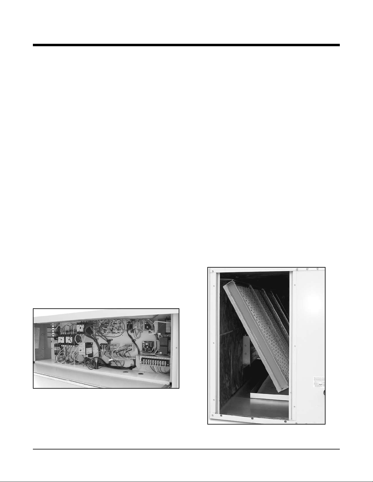
electrical panel without impairing unit operation.
Compressor Compartment
Catalog 1110 Rooftop Water Source Heat Pumps Page 3 of 62
Page 5

Design Features – RWD, RGD
Compressor Protection
All compressors have crankcase heaters and internal overheat protection.
Compressor Control Module
The sequence begins with a three second start delay, a
ninety second bypass of low pressure cutout switch at start-
up, and a ve minute anti-short-cycle time delay (delay
begins upon opening of thermostat). Compressor operation
is locked out upon opening of high-pressure cutout or low
pressure cutout (after 90 second start-up delay expires).
Units can be reset remotely at a thermostat or by removing
and reapplying power to unit. Units can be switched to 24-
vac output for remote fault indication (eld option).
Separate Refrigeration Circuits
Multiple refrigeration circuits are standard on sizes 096
thru 420. Multicompressor models provide the added
benet of partial standby. Also, they provide two-stage
operation with one compressor being activated from the
rst stage of the two-stage space thermostat on the cooling
cycle. On the heating cycle, all compressors are activated
by the rst stage of the space thermostat.
Indoor Air Coil
The indoor air coils have aluminum ns formed on multiple
rows of seamless copper tubing arranged in a staggered
tube conguration. The tubes are mechanically expanded,
rmly bonding the tube to the collar of each n.
The Coaxial Water Coil
The Coaxial Water Coil consists of an enhanced surface
inner copper tube with outer steel tube (tube-in-tube).
Water connections are stubbed off inside the cabinet. Field
piped return and supply water lines enter through individual
sleeves in the compressor base pan section after passing
through the roof curb. Units are shipped with water pressure taps and upper elbows for easy connection to the water
source. RGD models are equipped with fully insulated refrigerant and water lines and a polyurethane foam encased
coaxial water coil.
Evaporator Blower and Motor
A forward-curved, statically and dynamically balanced
DWDI centrifugal blower(s) is used for the supply air.
Blower wheels are fabricated of galvanized steel. Blower
housings are fabricated of galvanized or epoxy coated steel.
The blower wheel(s) is mounted on a solid steel shaft supported by sealed ball bearings. The shaft is belt driven with
adjustable drive sheaves connected to a nominal 1725-rpm
motor with sealed ball bearings. The sealed bearings on
both the blower shaft and motor are permanently lubricated.
Motors up to 3 horsepower are internally protected (auto
reset) and motors 5 horsepower and larger are externally
protected (manual reset).
Blower and Motor Compartment
Foam Encased Coaxial Water Coil
Page 4 of 62 Rooftop Water Source Heat Pumps Catalog 1110
Page 6
Design Features – RWD, RGD
Refrigerant Circuit
Included in each refrigerant circuit is a reversing valve,
high-pressure unit protection control, low pressure unit
protection control/loss of charge protector , dual gauge con-
nections for high and low pressure readings, and a bi-ow
thermostatic expansion valve. The expansion valve has adjustable superheat and distributors to meter the refrigerant
evenly to the evaporator refrigerant circuits. The 24-volt
reversing valve is energized in the cooling mode, making it
fail safe to the heating mode.
Factory-installed service ports in compressor suction, discharge and liquid lines are included for ease of servicing. A
common refrigerant line connection is also provided for use
with water regulating valves.
Electric Controls
Internally wired controls include the compressor control
module, reversing valve relay, fan relay and the blower and
compressor motor contactors or starters mounted in a sheet
metal control panel. The isolated 24-volt control circuit
includes a transformer and low voltage terminal board for
external thermostat control hookup.
Terminal Board Connections
Terminal boards are furnished for 24-volt thermostat connections on units.
Sloped Stainless Steel Condensate
Drain Pan
The condensate drain pan is sloped to comply with
ASHRAE Standard 62-1089R and fabricated from stainless steel. The bottom is insulated with 5/8" closed cell
neoprene insulation. Condensation may be drained from
either side of the unit from MPT drain ttings positioned at
the exterior of each side of the cabinet (sizes 036, 048, 060,
and 072 are equipped for one side drain only).
Power Entry
Power entering through the curb sleeves is standard in all
models.
Multiple Refrigeration Circuits
Unit sizes 096 and larger use either two or three separate
refrigeration circuits. This design offers two stages of
cooling for load shedding when conditions allow. Three
compressor units energize two of the refrigeration circuits
for the rst stage of cooling and the third is reserved for
maximum conditions. The heating cycle uses all three circuits at start up and unloads one circuit as conditions allow.
Multiple compressors on independent circuits also offer
the added benet of continuous operation in the event of a
failure in one of the circuits.
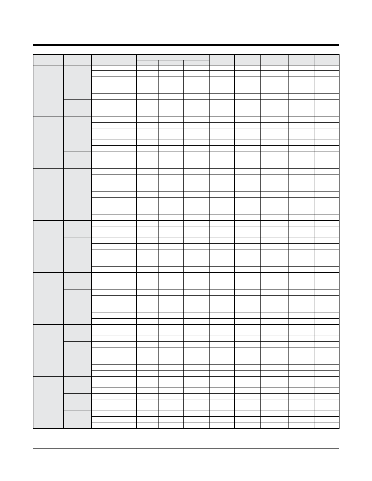
Filters
All models are shipped with 2-inch thick disposable glass
ber media lters mounted in a factory installed at lter
rack on the return air opening.
Control Board
Disposable Glass Fiber Media Filter
Catalog 1110 Rooftop Water Source Heat Pumps Page 5 of 62
Page 7

Optional Features – RWD, RGD
Coil Coatings:
■ Baked phenolic.
Corrosion Protection Options:
■ Harsh environment protection plus
Refrigerant Circuit Components
& Controls:
■ Hot gas reheat.
Evaporator Motors:
■ ODP evaporator blower motor, nominal efciency.
■ ODP evaporator blower motor, high efciency.
■ Totally enclosed blower motor.
Filters:
■ 2-inch aluminum metal mesh lters.
■ 2-inch extended surface pleated lters (30% efcient).
Electrical Options:
■ Clogged lter indicator.
■ 115-volt GFCI convenience outlet.
■ Firestat, return air mounted manual reset limit control.
■ Non-fused disconnect NEMA3R enclosure.
Controls:
■ 24-volt with terminal strip.
■ Microprocessor.
Outdoor Air Ventilation:
■ No ventilation.
■ Manual 20% outdoor air damper.
■ Motorized proportional outdoor air damper.
■ ASHRAE cycle III economizer, with enthalpy
changeover control.
Supplemental Heat Options:
■ Electric Heat (see accessories).
Specialty Coils:
■ Cupro-nickel coaxial coil.
Refrigerant:
■ R-407C available.
Copper Tube, Copper Fin DX Evaporator Coil
Page 6 of 62 Rooftop Water Source Heat Pumps Catalog 1110
Page 8

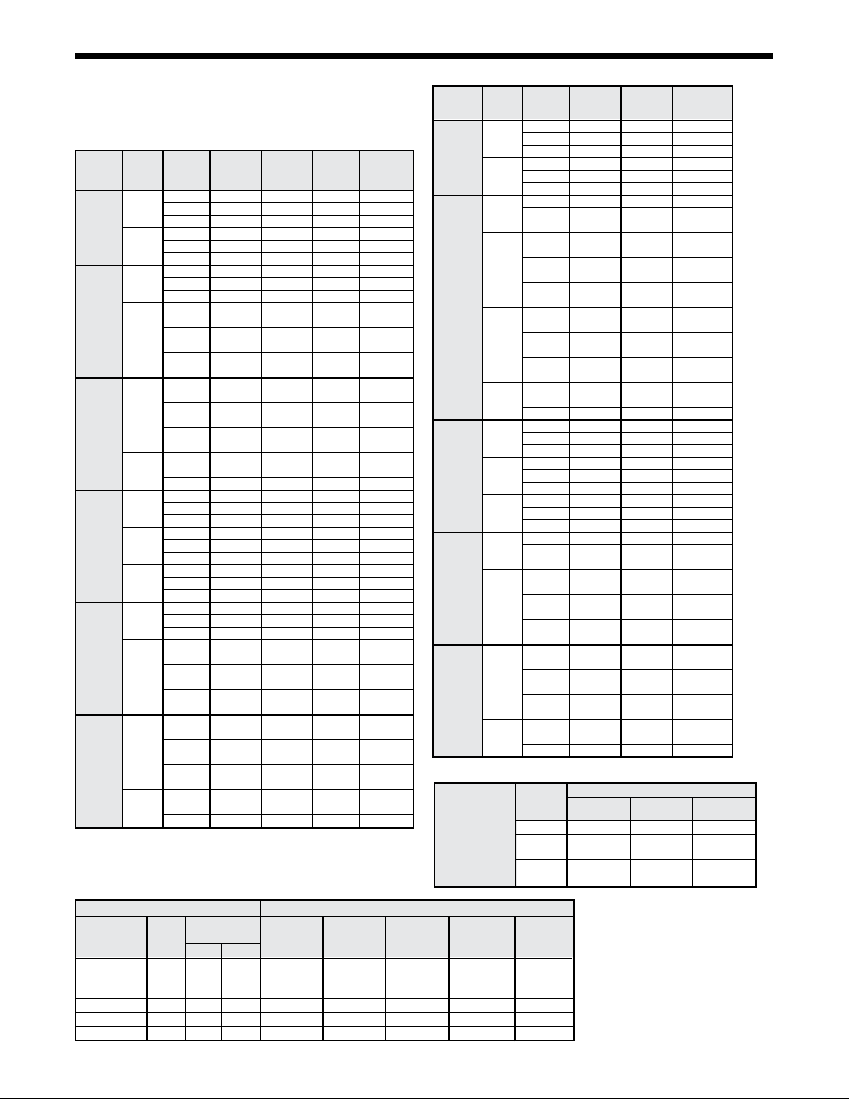
ISO Performance Data – RWD (Water Loop)
Downow Discharge Units
Table 1.
UNIT AIRFLOW WATER FLOW COOLING HEATING
SIZE
CFM L
208-230/60/3
036 1200 566 8.6 0.54 460/60/3 34,500 10,104 14.1 42,900 12,565 4.4
380/415/50/3
208-230/60/3
048 1800 850 13.0 0.82 460/60/3 49,600 14,526 13.0 59,600 17,455 4.5
380/415/50/3
208-230/60/3
060 2000 944 15.5 0.98 460/60/3 60,600 17,748 12.8 73,000 21,380 4.6
380/415/50/3
208-230/60/3
072 2300 1086 18.0 1.14 460/60/3 75,200 22,024 12.8 83,300 24,397 4.6
380/415/50/3
208-230/60/3
096 3200 1510 24.0 1.52 460/60/3 95,000 27,823 12.5 173,000 33,095 4.2
380/415/50/3
208-230/60/3
120 4000 1888 31.0 1.96 460/60/3 119,000 34,852 12.0 140,000 41,003 4.2
380/415/50/3
208-230/60/3
150 5000 2360 36.0 2.27 460/60/3 150,700 44,136 12.5 185,000 54,182 4.3
380/415/50/3
208-230/60/3
180 6000 2832 42.0 2.65 460/60/3 171,900 50,345 13.9 208,000 60,918 4.6
380/415/50/3
208-230/60/3
240 8000 3776 58.0 3.66 460/60/3 229,800 67,303 12.5 287,100 84,085 4.3
380/415/50/3
208-230/60/3
300 10,000 4720 68.0 4.29 460/60/3 276,400 80,951 13.6 343,100 100,486 4.6
380/415/50/3
208-230/60/3
360 12,000 5663 93.0 5.87 460/60/3 376,500 110,267 12.4 459,100 134,459 4.2
380/415/50/3
208-230/60/3
420 14,000 6607 108.0 6.81 460/60/3 426,700 124,970 12.1 550,000 161,081 4.2
380/415/50/3
Notes:
EER=EnergyEfciencyRatio;COP=CoefcientofPerformance.
Cooling capacity is based on 80.6oF (27oC) db, 66.2oF (19oC) wb entering air temperature and 86oF (30oC) entering, 95oF (35oC) leaving water temperature. Heating
capacity based on 68oF (20oC) db entering air temperature and 68oF (20oC)enteringwater temperature.Netcapacitiesincludefanmotorheat;50cycleunitsare
derated, 60 cycle units.
/s GPM L/s
VOLTAGE
BTU
/HR WATTS EER BTU/HR WATTS COP
Catalog 1110 Rooftop Water Source Heat Pumps Page 7 of 62
Page 9

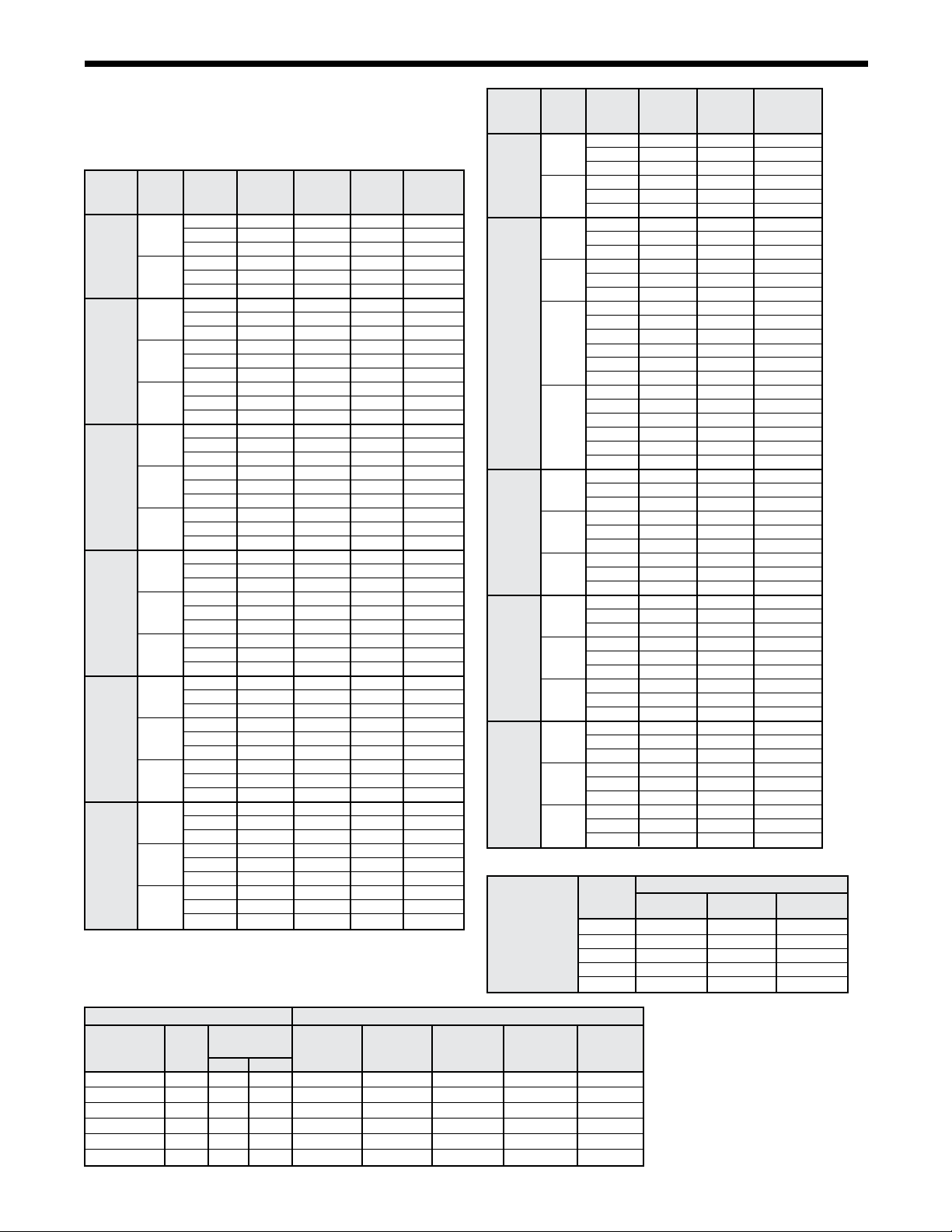
ISO Performance Data – RGD (Ground Loop)
Downow Discharge Units
Table 2.
UNIT AIRFLOW WATER FLOW COOLING HEATING
SIZE
CFM L
208-230/60/3
036 1200 566 8.6 0.54 460/60/3 38,500 11,276 14.9 24,100 7,058 3.5
380/415/50/3
208-230/60/3
048 1800 850 13.0 0.82 460/60/3 52,000 15,230 14.9 35,000 10,251 3.5
380/415/50/3
208-230/60/3
060 2000 944 15.5 0.98 460/60/3 60,200 17,631 14.1 47,000 13,756 3.2
380/415/50/3
208-230/60/3
072 2300 1086 18.0 1.14 460/60/3 75,300 22,346 15.9 55,400 16,225 3.7
380/415/50/3
208-230/60/3
096 3200 1510 24.0 1.52 460/60/3 96,000 28,116 13.5 71,400 20,911 3.2
380/415/50/3
208-230/60/3
120 4000 1888 31.0 1.96 460/60/3 120,000 35,145 13.4 93,100 27,267 3.2
380/415/50/3
208-230/60/3
150 5000 2360 36.0 2.27 460/60/3 154,000 45,103 13.6 120,500 35,291 3.2
380/415/50/3
208-230/60/3
180 6000 2832 42.0 2.65 460/60/3 178,200 52,190 15.7 133,600 39,128 3.5
380/415/50/3
208-230/60/3
240 8000 3776 58.0 3.66 460/60/3 236,900 69,382 14.5 180,600 52,893 3.4
380/415/50/3
208-230/60/3
300 10,000 4720 68.0 4.29 460/60/3 285,000 83,469 14.8 230,000 67,361 3.6
380/415/50/3
208-230/60/3
360 12,000 5663 93.0 5.87 460/60/3 383,100 112,200 14.0 304,100 89,063 3.2
380/415/50/3
208-230/60/3
420 14,000 6607 108.0 6.81 460/60/3 440,000 128,865 13.4 369,000 108,071 3.2
380/415/50/3
Notes:
EER=EnergyEfciencyRatio;COP=CoefcientofPerformance.
Cooling capacity is based on 80.6oF (27oC) db, 66.2oF (19oC) wb entering air temperature and 77oF (25oC) entering, 87oF (31oC) leaving water temperature. Heating
capacity based on 68oF (20oC) db entering air temperature and 32oF (0oC)entering watertemperature. Netcapacities includefanmotorheat;50 cycleunits are
derated, 60 cycle units.
/s GPM L/s
VOLTAGE
BTU
/HR WATTS EER BTU/HR WATTS COP
Page 8 of 62 Rooftop Water Source Heat Pumps Catalog 1110
Page 10
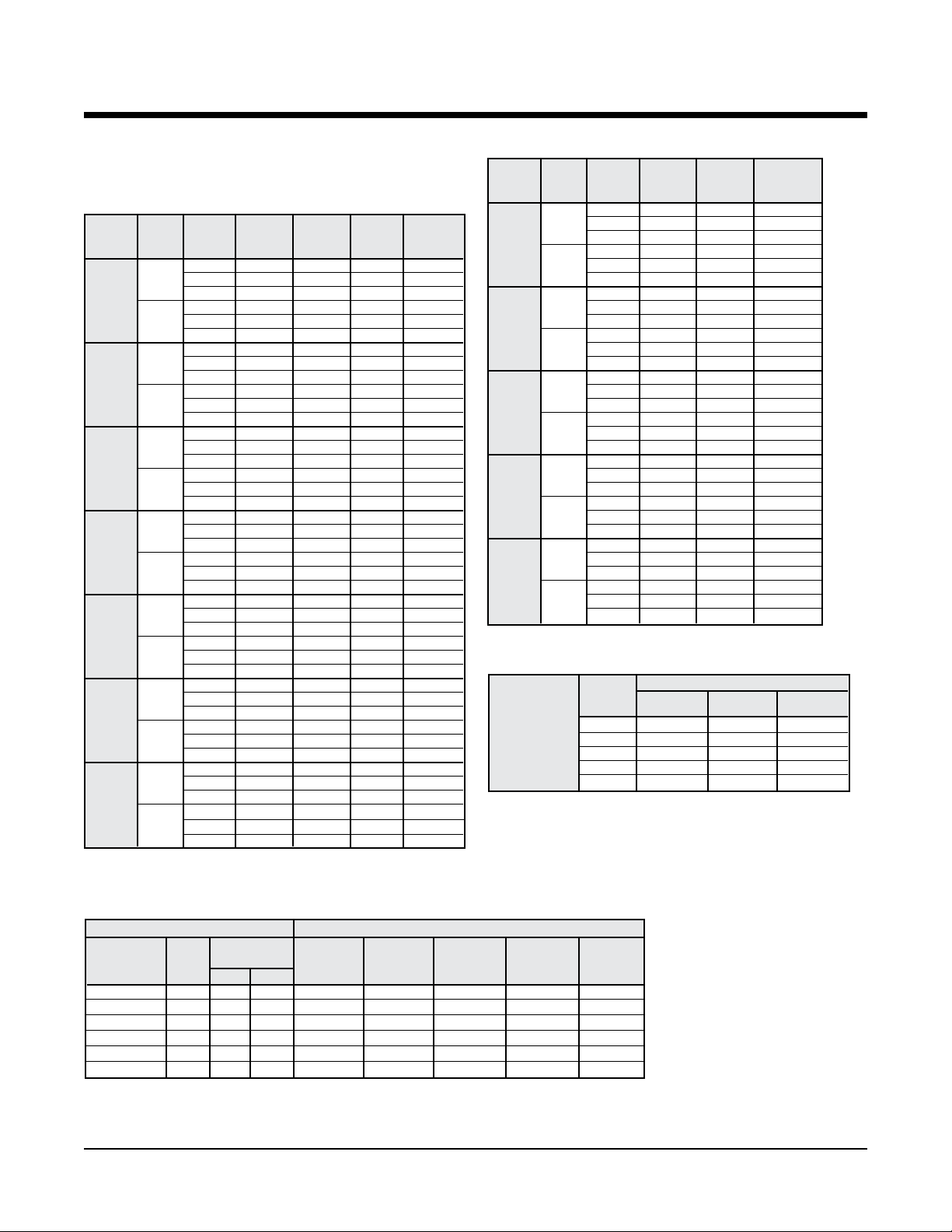
Electrical Data – RWD, RGD 036 – 150
HP Qty RLA (each) LRA (each)
1/2 460/60/3 1 4.8 36.0 1.4 6.2 414/506 7.4 15
380/50/3 1 4.8 36.0 1.2 6.0 342/420 7.2 15
208-230/60/3 1 8.7 68.0 2.8 11.5 197/253 13.7 20
036 3/4 460/60/3 1 4.8 36.0 1.4 6.2 414/506 7.4 15
380/50/3 1 4.8 36.0 2.1 6.9 342/420 8.1 15
208-230/60/3 1 8.7 68.0 3.4 12.1 197/253 14.3 20
1 460/60/3 1 4.8 36.0 1.7 7.5 414/506 7.7 15
380/50/3 1 4.8 36.0 1.9 6.7 342/420 7.9 15
3/4 460/60/3 1 5.8 42.0 1.4 7.2 414/506 8.7 15
380/50/3 1 5.8 42.0 2.1 7.9 342/420 9.4 15
208-230/60/3 1 12.8 91.0 3.4 16.2 197/253 19.4 30
048 1
1
380/50/3 1 5.8 42.0 2.7 8.5 342/420 9.9 15
3/4 460/60/3 1 6.8 49.5 1.4 8.2 414/506 9.9 15
380/50/3 1 6.8 49.5 2.1 8.9 342/420 10.6 15
208-230/60/3 1 17.4 124.0 3.4 20.8 197/253 25.2 40
060 1
1
208-230/60/3 1 20.0 156.0 3.4 23.4 197/253 28.4 45
1 460/60/3 1 9.0 75.0 1.7 10.7 414/506 12.9 20
380/50/3 1 9.0 75.0 1.9 10.9 342/420 13.2 20
208-230/60/3 1 20.0 156.0 4.6 24.6 197/253 29.6 45
072 11/2
208-230/60/3 1 20.0 156.0 6.2 26.2 197/253 31.2 50
2 460/60/3 1 9.0 75.0 3.1 12.1 414/506 14.4 20
380/50/3 1 9.0 75.0 3.5 12.5 342/420 14.8 20
1 460/60/3 2 6.5 46.5 1.7 14.7 414/506 16.3 20
380/50/3 2 6.5 46.5 1.9 14.9 342/420 16.5 20
096 11/2
380/50/3 2 6.5 46.0 2.7 15.7 342/420 17.3 20
2 460/60/3 2 6.5 46.0 3.1 15.5 414/506 17.7 20
380/50/3 2 6.5 46.0 3.5 15.9 342/420 18.1 20
1
380/50/3 2 8.1 66.5 2.7 18.9 342/420 20.9 25
120 2 460/60/3 2 8.1 63.0 3.1 19.3 414/506 21.3 25
208-230/60/3 2 16.1 128.0 8.0 40.2 197/253 44.2 60
3 460/60/3 2 8.1 63.0 4.0 20.2 414/506 22.2 30
380/50/3 2 8.1 63.0 4.8 21.0 342/420 23.0 30
1
380/50/3 2 9.0 75.5 2.7 20.7 342/420 23.0 30
208-230/60/3 2 20.0 156.0 6.2 46.2 197/253 51.2 70
150 2
380/50/3 2 9.0 75.5 3.5 21.5 342/420 23.8 30
208-230/60/3 2 20.0 156.0 8.0 48.0 197/253 53.0 70
3
380/50/3 2 9.0 75.5 4.8 22.8 342/420 25.1 30
Unit Size
Fan Motor
1
/2
1
/2
1
/2
1
/2
Compressor Fan Motor Total Unit Min./Max. Min. Circuit Max Fuse
Voltage
208-230/60/3 1 8.7 68.0 2.8 11.5 197/253 13.7 20
208-230/60/3 1 12.8 91.0 2.8 15.6 197/253 18.8 30
460/60/3 1 5.8 42.0 1.7 7.5 414/506 8.9 15
380/50/3 1 5.8 42.0 1.9 7.7 342/420 9.2 15
208-230/60/3 1 12.8 91.0 4.6 17.4 197/253 20.6 30
460/60/3 1 5.8 42.0 2.3 8.1 414/506 9.6 15
208-230/60/3 1 17.4 123.0 2.8 20.2 197/253 24.6 40
460/60/3 1 6.8 59.6 1.7 8.5 414/506 10.2 15
380/50/3 1 6.8 59.6 1.9 8.7 342/420 10.4 15
208-230/60/3 1 17.4 124.0 4.6 22.0 197/253 26.4 40
460/60/3 1 6.8 59.6 2.3 9.1 414/506 10.8 15
380/50/3 1 6.8 59.6 2.7 9.5 342/420 11.2 15
460/60/3 1 9.0 75.0 2.3 11.3 414/506 13.6 20
380/50/3 1 9.0 75.0 2.7 11.7 342/420 13.9 20
208-230/60/3 2 12.9 93.0 3.4 29.2 197/253 32.4 45
208-230/60/3 2 12.9 91.0 4.6 30.4 197/253 33.6 45
460/60/3 2 6.5 46.0 2.3 15.3 414/506 16.9 20
208-230/60/3 2 12.9 91.0 6.2 32.0 197/253 35.2 45
208-230/60/3 2 16.1 125.0 4.6 36.8 197/253 40.8 50
460/60/3 2 8.1 66.5 2.3 18.5 414/506 20.5 25
208-230/60/3 2 16.1 128.0 6.2 38.4 197/253 42.4 50
380/50/3 2 8.1 63.0 3.5 19.7 342/420 21.7 25
208-230/60/3 2 20.0 156.0 4.6 44.6 197/253 49.6 60
460/60/3 2 9.0 75.5 2.3 20.3 414/506 22.6 30
460/60/3 2 9.0 75.5 3.1 21.1 414/506 23.4 30
460/60/3 2 9.0 75.5 4.0 22.0 414/506 24.3 30
FLA Amps Volts Ampacity Size
Catalog 1110 Rooftop Water Source Heat Pumps Page 9 of 62
Page 11

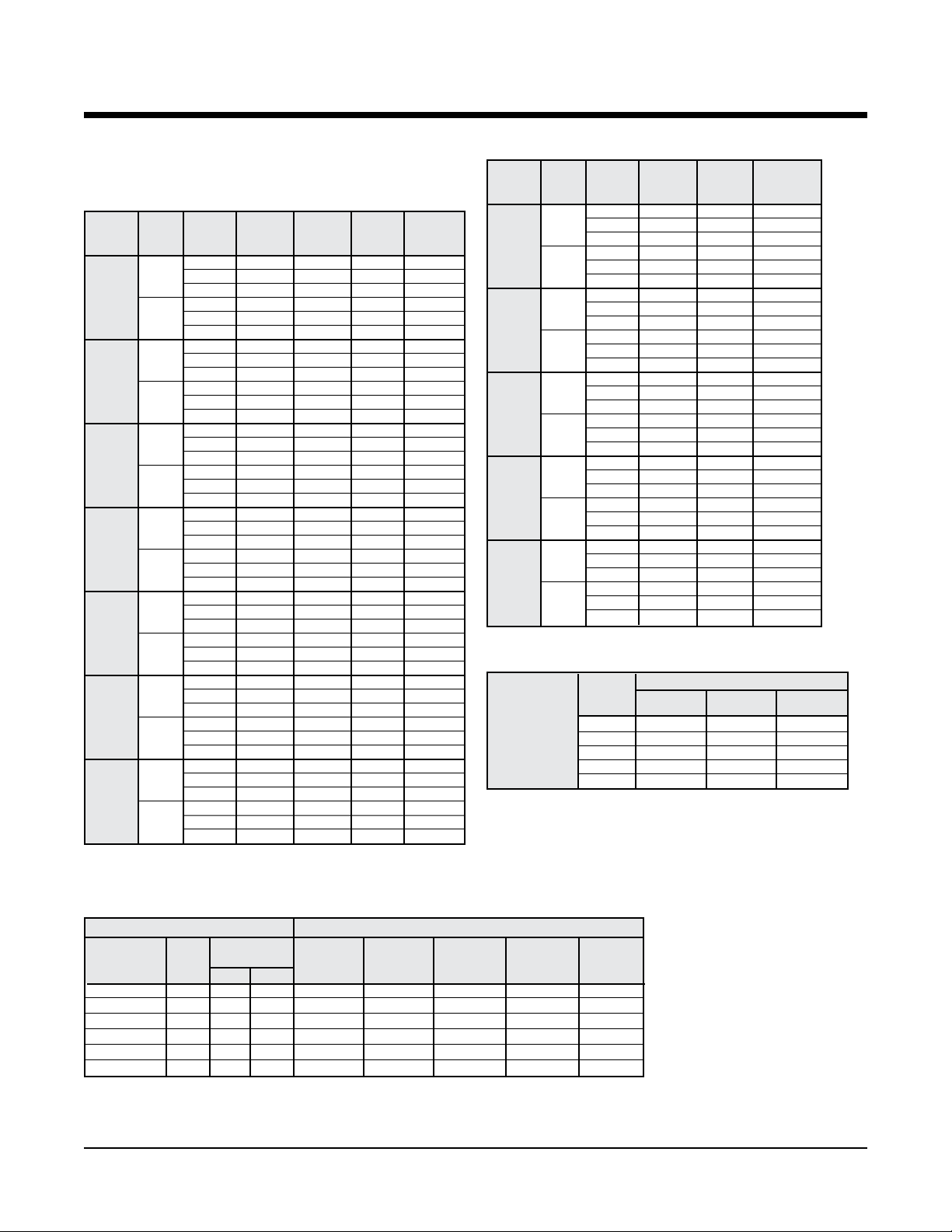
Electrical Data – RWD, RGD 180 – 420
208-230/60/3 2 22.5 164.0 6.2 51.2 197/253 56.8 70
2 460/60/3 2 10.9 100.0 3.1 24.9 414/506 27.6 35
380/50/3 2 10.9 100.0 3.5 25.3 342/420 28.0 35
208-230/60/3 2 22.5 164.0 8.0 53.0 197/253 58.6 80
180 3 460/60/3 2 10.9 100.0 4.0 25.8 414/506 28.5 35
380/50/3 2 10.9 100.0 4.8 26.6 342/420 29.3 40
208-230/60/3 2 22.5 164.0 13.4 58.4 197/253 64.0 80
5 460/60/3 2 10.9 100.0 6.7 28.5 414/506 31.2 40
380/50/3 2 10.9 100.0 7.8 29.6 342/420 32.3 40
208-230/60/3 2 30.9 225.0 13.4 75.2 197/253 82.9 110
5 460/60/3 2 15.6 114.0 6.7 37.9 414/506 41.8 50
240 380/50/3 2 15.6 114.0 7.8 39.0 342/420 42.9 50
208-230/60/3 2 30.9 225.0 20.0 81.8 197/253 89.5 110
7
380/50/3 2 15.6 114.0 11.5 42.7 342/420 46.6 60
208-230/60/3 2 37.8 239.0 13.4 89.0 197/253 98.5 125
5 460/60/3 2 17.3 125.0 6.7 41.3 414/506 45.6 60
380/50/3 2 17.3 125.0 7.8 42.4 342/420 46.7 60
208-230/60/3 2 37.8 239.0 20.0 95.6 197/253 105.1 125
300 71/2 460/60/3 2 17.3 125.0 10.0 44.6 414/506 48.9 60
380/50/3 2 17.3 125.0 11.5 46.1 342/420 50.4 60
208-230/60/3 2 37.8 239.0 28.0 103.6 197/253 113.1 150
10 460/60/3 2 17.3 125.0 14.0 48.6 414/506 52.9 70
380/50/3 2 17.3 125.0 14.0 48.6 342/420 52.9 70
208-230/60/3 2 52.6 425.0 20.0 125.2 197/253 138.4 175
7
360 380/50/3 2 23.8 187.0 11.5 59.1 342/420 65.1 80
208-230/60/3 2 52.6 425.0 28.0 133.2 197/253 146.4 175
10 460/60/3 2 23.8 187.0 14.0 61.6 414/506 67.5 90
380/50/3 2 23.8 187.0 14.0 61.6 342/420 67.5 90
208-230/60/3 3 37.8 239.0 28.0 141.4 197/253 150.9 175
10 460/60/3 3 17.3 125.0 14.0 65.9 414/506 70.2 80
420 380/50/3 3 17.3 125.0 14.0 65.9 342/420 70.2 80
208-230/60/3 3 37.8 239.0 38.6 152.0 197/253 161.5 175
15 460/60/3 3 17.3 125.0 19.3 71.2 414/506 75.5 90
380/50/3 3 17.3 125.0 19.3 71.2 342/420 75.5 90
Unit Size
Fan Motor
HP
1
/2 460/60/3 2 15.6 114.0 10.0 41.2 414/506 45.1 60
1
/2 460/60/3 2 23.8 187.0 10.0 57.6 414/506 63.6 80
Voltage
Compressor
Qty RLA (each) LRA (each) FLA Amps Volts Ampacity Size
Fan Motor Total Unit Min./Max. Min. Circuit Max Fuse
Page 10 of 62 Rooftop Water Source Heat Pumps Catalog 1110
Page 12

Capacity Data – RWD, RGD 036
Cooling capacities shown are gross capacities. For net capacities,
multiply blower bhp required times 2545 Btu per bph and subtract
from total and sensible in tables.
Table 8. Cooling
o
EWT(
F) gpm cfm Capacity
1,100 45,810 32,040 1,230 50,000
6.1 1,200 46,490 33,490 1,230 50,700
40 1,300 47,100 34,850 1,240 51,330
1,100 46,460 32,310 1,120 50,280
8.6 1,200 47,180 33,740 1,120 51,020
1,300 47,780 35,180 1,130 51,630
1,100 43,990 31,450 1,490 49,080
6.1 1,200 44,680 32,780 1,490 49,780
1,300 45,170 34,280 1,500 50,310
1,100 44,330 31,590 1,440 49,260
50 7.2 1,200 45,030 32,920 1,450 49,970
1,300 45,590 34,320 1,450 50,550
1,100 44,680 31,620 1,400 49,450
8.6 1,200 45,340 33,070 1,400 50,130
1,300 45,920 34,450 1,410 50,720
1,100 40,340 29,790 1,940 46,970
6.1 1,200 40,860 31,240 1,950 47,520
1,300 41,510 32,650 1,960 48,210
1,100 40,610 30,040 1,910 47,130
70 7.2 1,200 41,230 31,310 1,910 47,760
1,300 41,850 32,800 1,920 48,430
1,100 40,900 30,150 1,880 47,310
8.6 1,200 41,530 31,440 1,880 47,950
1,300 42,160 32,930 1,890 48,620
1,100 34,860 27,750 2,090 41,990
6.1 1,200 35,310 29,140 2,100 42,480
1,300 35,750 30,370 2,110 42,940
1,100 35,140 27,860 2,060 42,180
85 7.2 1,200 35,610 29,260 2,070 42,680
1,300 36,010 30,610 2,080 43,110
1,100 35,440 27,870 2,030 42,380
8.6 1,200 35,870 29,360 2,040 42,850
1,300 36,290 30,720 2,050 43,290
1,100 32,030 26,500 2,340 40,030
6.1 1,200 32,420 27,860 2,350 40,460
1,300 32,720 29,300 2,360 40,790
1,100 32,300 26,610 2,320 40,220
100 7.2 1,200 32,700 27,970 2,330 40,660
1,300 33,010 29,420 2,340 41,000
1,100 32,550 26,710 2,300 40,400
8.6 1,200 32,960 28,060 2,310 40,850
1,300 33,270 29,520 2,320 41,190
1,100 30,040 25,710 2,490 38,560
6.1 1,200 30,340 27,200 2,510 38,900
1,300 30,660 28,450 2,520 39,260
1,100 30,300 25,810 2,480 38,760
110 7.2 1,200 30,610 27,300 2,490 39,100
1,300 30,900 28,640 2,500 39,450
1,100 30,540 25,910 2,460 38,930
8.6 1,200 30,850 27,400 2,470 39,290
1,300 31,160 28,900 2,480 39,630
Total
Btu/h Btu/h
Heat
SH
Watts Rejected
Btu/h
Heating Heat
o
EWT(
F) gpm cfm Capacity Watts Absorpted
Btu/h Btu/h
1,100 20,860 1,450 15,900
6.1 1,200 20,890 1,410 16,060
30 1,300 20,910 1,380 16,200
1,100 21.490 1,490 16,410
8.6 1,200 21,520 1,450 16,580
1,300 21,550 1,410 16,730
1,100 25,310 1,650 19,670
6.1 1,200 25,350 1,610 19,870
40 1,300 25,370 1,560 20,040
1,100 26,090 1,690 20,320
8.6 1,200 26,140 1,640 20,540
1,300 26,170 1,600 20,720
1,100 30,200 1,910 23,700
6.1 1,200 30,280 1,850 23,950
1,300 30,320 1,800 24,160
1,100 30,710 1,930 24,130
50 7.2 1,200 30,790 1,870 24,390
1,300 30,840 1,830 24,610
1,100 31,170 1,950 24,520
8.6 1,200 31,260 1,900 24,790
1,300 31,320 1,850 25,020
1,100 35,180 2,130 27,900
6.1 1,200 35,310 2,080 28,220
1,300 35,400 2,030 28,490
1,100 35,760 2,160 28,390
60 7.2 1,200 35,900 2,100 28,720
1,300 36,010 2,050 29,000
1,100 36,290 2,180 28,840
8.6 1,200 36,450 2,130 29,180
1,300 36,570 2,080 29,470
1,100 40,030 2,320 32,090
6.1 1,200 40,240 2,270 32,490
1,300 40,410 2,220 32,820
1,100 40,690 2,350 32,650
70 7.2 1,200 40,930 2,300 33,060
1,300 41,110 2,260 33,410
1,100 41,340 2,390 33,200
8.6 1,200 41,600 2,340 33,620
1,300 41,800 2,290 33,980
1,100 45,170 2,550 36,450
6.1 1,200 45,500 2,510 36,940
1,300 45,770 2,460 37,350
1,100 45,960 2,590 37,120
80 7.2 1,200 46,320 2,550 37,630
1,300 46,610 2,500 38,060
1,100 46,660 2,620 37,720
8.6 1,200 47,060 2,580 38,250
1,300 47,370 2,540 38,700
Table 8d. Heating Correction Multipliers
Heating
Correction
Ent. Air
Heating Heat of Total
o
F dbt
Btu/h Absorp. Watts
Multipliers 60 1.014 1.038 0.925
Various 65 1.007 1.019 0.963
Entering Air oF 70 1 1 1
dbt Temperature 75 0.993 0.981 1.077
80 0.986 0.961 ––
Multipliers
Table 8b. Cooling Performance Correction Factors
Table 8c. Heating
Condenser Water Flow Cooling Performance Correction Factors
Cooling Pressure Total Heat Sensible
Cycle gpm
Design ∆T psi Ft.HD. Btu/h
o
8
10
12
14
16
20
10.6 7.2 16.6 1.005 0.987 1.002 1.001 1.02
o
8.6 4.7 10.9 1.000 1.000 1.000 1.000 1.00
o
7.1 3.1 7.2 0.987 1.012 0.992 0.996 0.98
o
6.1 2.3 5.4 0.973 1.025 0.985 0.992 0.95
o
5.3 2.0 4.6 0.960 1.037 0.977 0.988 0.93
o
4.3 1.2 2.8 0.958 1.054 0.973 0.980 0.91
Drop
Capacity
Watts
Rejection Capacity EER
Input
Btu/h Btu/h
Notes:
1. Above ratings are based on 80
o
F dbt, 67oF
wbt entering air in cooling, 70oF dbt in
heating. For other entering air conditions
see correction factor charts.
2. Above ratings do not include allowance
for water pump power consumption.
3. Heating ratings below 45
o
EWT based
on the use of 20% methanol/water anti-
freeze.
4. Interpolation of ratings is permitted.
5. Above ratings are at 208 volts.
1110 Rooftop Water Source Heat Pumps Page 11 of 62
Page 13

Capacity Data – RWD, RGD 048
Table 9c. Heating
Cooling capacities shown are gross capacities. For net capacities,
multiply blower bhp required times 2545 Btu per bph and subtract
from total and sensible in tables.
Table 9. Cooling
Total SH Heat
o
EWT(
F) gpm cfm Capacity Btu/h Watts Rejected
Btu/h Btu/h
1,700 64,590 46,720 2,230 72,200
8.5 1,800 65,270 47,840 2,230 72,880
40 1,900 65,640 49,320 2,240 73,290
1,700 65,590 47,110 2,130 72,840
13 1,800 66,280 48,260 2,130 73,540
1,900 66,810 49,540 2,130 74,080
1,700 62,230 45,660 2,470 70,670
8.5 1,800 62,820 46,860 2,480 71,270
1,900 63,230 48,230 2,490 71,710
1,700 62,850 45,850 2,410 71,080
50 10.5 1,800 63,420 47,100 2,420 71,660
1,900 63,760 48,600 2,430 72,040
1,700 63,270 45,970 2,370 71,360
13 1,800 63,820 47,270 2,380 71,930
1,900 64,180 48,760 2,390 72,320
1,700 56,940 43,710 2,980 67,120
8.5 1,800 57,420 44,940 2,990 67,620
1,900 58,060 46,220 3,000 68,290
1,700 57,500 43,920 2,930 67,500
70 10.5 1,800 58,070 45,010 2,930 68,080
1,900 58,620 46,480 2,950 68,670
1,700 57,890 44,030 2,890 67,770
13 1,800 58,330 45,390 2,900 68,230
1,900 58,910 46,830 2,910 68,840
1,700 51,270 41,280 3,110 69,530
8.5 1,800 51,590 42,740 3,130 62,260
1,900 51,960 43,980 3,140 62,670
1,700 51,700 41,710 3,070 62,170
85 10.5 1,800 52,140 42,940 3,080 62,640
1,900 52,520 44,190 3,090 63,060
1,700 52,060 41,840 3,040 62,420
13 1,800 52,600 42,900 3,040 62,980
1,900 52,900 44,330 3,050 63,320
1,700 47,130 39,590 3,470 58,980
8.5 1,800 47,390 41,060 3,490 59,300
1,900 47,760 42,180 3,500 59,700
1,700 47,630 39,800 3,430 59,330
100 10.5 1,800 47,910 41,250 3,450 59,680
1,900 48,240 42,520 3,460 60,050
1,700 47,880 40,150 3,410 59,500
13 1,800 48,350 41,180 3,410 60,000
1,900 48,590 42,640 3,430 60,290
1,700 44,150 38,650 3,710 56,830
8.5 1,800 44,530 39,760 3,720 57,240
1,900 44,760 41,130 3,740 57,530
1,700 44,720 38,630 3,670 57,240
110 10.5 1,800 44,970 40,110 3,690 57,560
1,900 45,260 41,330 3,700 57,900
1,700 45,040 38,770 3,640 57,480
13 1,800 45,300 40,240 3,660 57,800
1,900 45,600 41,470 3,680 58,150
Table 9b. Cooling Performance Correction Factors
Condenser Water Flow Cooling Performance Correction Factors
Cooling Pressure Total Heat Sensible
Cycle gpm
Drop
Capacity
Design ∆T psi Ft.HD. Btu/h
8o 15.7 8.5 19.7 1.005 0.957 1.002 1.001 1.02
10
12
14
16
20
o
13 5.9 13.7 1.000 1.000 1.000 1.000 1.00
o
10.4 3.9 9.0 0.987 1.012 0.992 0.996 0.98
o
8.9 2.9 6.7 0.973 1.025 0.985 0.992 0.95
o
7.8 2.2 5.2 0.960 1.037 0.977 0.988 0.93
o
6.3 1.5 3.4 0.958 1.054 0.973 0.980 0.91
Watts
Rejection Capacity EER
Input
Btu/h Btu/h
Page 12 of 62 Rooftop Water Source Heat Pumps 1110
Heating Heat
o
EWT(
F) gpm cfm Capacity Watts Absorpted
Btu/h Btu/h
1,700 32,000 2,270 24,260
8.5 1,800 32,040 2,250 24,350
30 1,900 32,170 2,250 24,490
1,700 32,920 2,300 25,080
13 1,800 33,020 2,290 25,210
1,900 33,110 2,280 25,330
1,700 37,770 2,480 29,300
8.5 1,800 37,890 2,470 29,470
40 1,900 37,990 2,460 29,610
1,700 38,950 2,520 30,340
13 1,800 39,070 2,510 30,520
1,900 39,190 2,500 30,670
1,700 43,880 2,700 34,680
8.5 1,800 44,020 2,680 34,890
1,900 44,150 2,660 35,070
1,700 44,660 2,720 35,370
50 10.5 1,800 44,820 2,700 35,590
1,900 44,960 2,690 35,790
1,700 45,230 2,740 35,870
13 1,800 45,390 2,720 36,100
1,900 45,540 2,710 36,300
1,700 50,260 2,910 40,310
8.5 1,800 50,440 2,890 40,580
1,900 50,600 2,870 40,820
1,700 51,190 2,950 41,130
60 10.5 1,800 51,390 2,920 41,410
1,900 51,590 2,900 41,690
1,700 51,870 2,970 41,730
13 1,800 52,100 2,940 42,060
1,900 52,280 2,920 42,320
1,700 56,890 3,150 46,150
8.5 1,800 57,110 3,120 46,480
1,900 57,310 3,090 46,780
1,700 58,010 3,190 47,140
70 10.5 1,800 58,250 3,150 47,500
1,900 58,470 3,120 47,810
1,700 58,790 3,210 47,840
13 1,800 59,050 3,180 48,210
1,900 59,270 3,150 48,540
1,700 63,680 3,380 52,150
8.5 1,800 63,960 3,340 52,570
1,900 64,210 3,300 52,950
1,700 64,970 3,420 53,290
80 10.5 1,800 65,270 3,380 53,740
1,900 65,540 3,340 54,140
1,700 65,820 3,450 54,040
13 1,800 66,140 3,410 54,510
1,900 66,410 3,370 54,930
Table 9d. Heating Correction Multipliers
Heating
Correction
Ent. Air
Heating Heat of Total
o
F dbt
Btu/h Absorp. Watts
Multipliers 60 1.014 1.038 0.925
Various 65 1.007 1.019 0.963
Entering Air oF 70 1 1 1
dbt Temperature 75 0.993 0.981 1.077
80 0.986 0.961 ––
Notes:
1. Above ratings are based on 80
2. Above ratings do not include allowance
3. Heating ratings below 45
4. Interpolation of ratings is permitted.
5. Above ratings are at 208 volts.
Multipliers
wbt entering air in cooling, 70oF dbt in
heating. For other entering air conditions
see correction factor charts.
for water pump power consumption.
o
EWT based
on the use of 20% methanol/water anti-
freeze.
o
F dbt, 67oF
Page 14
Capacity Data – RWD, RGD 060
Table 10c. Heating
Cooling capacities shown are gross capacities. For net capacities,
multiply blower bhp required times 2545 Btu per bph and subtract
from total and sensible in tables.
Table 10. Cooling
Total SH Heat
o
EWT(
F) gpm cfm Capacity Btu/h Watts Rejected
11
40
15.5
11
50 13
15.5
11
70 13
15.5
11
85 13
15.5
11
100 13
15.5
11
110 13
15.5
1,800 75,430 52,770 2,640 84,430
2,000 76,660 55,660 2,650 85,710
2,200 77,680 58,510 2,670 86,780
1,800 76,030 53,070 2,560 84,780
2,000 77,330 55,950 2,580 86,120
2,200 78,370 58,840 2,590 87,220
1,800 73,490 51,990 2,860 83,240
2,000 74,700 54,860 2,870 84,500
2,200 75,670 57,720 2,890 85,520
1,800 73,850 52,140 2,820 83,450
2,000 75,070 55,010 2,830 84,730
2,200 76,060 57,870 2,840 85,760
1,800 74,160 52,270 2,780 83,640
2,000 75,400 55,140 2,790 84,930
2,200 76,400 58,000 2,810 85,970
1,800 69,200 50,230 3,420 80,870
2,000 70,270 53,120 3,440 82,000
2,200 71,260 55,620 3,440 83,010
1,800 69,570 50,380 3,370 81,060
2,000 70,660 53,260 3,380 82,200
2,200 71,650 55,800 3,390 83,220
1,800 69,890 50,510 3,320 81,230
2,000 70,990 53,400 3,340 82,380
2,200 71,870 56,330 3,350 83,300
1,800 65,680 48,850 3,950 79,170
2,000 66,750 51,430 3,960 80,270
2,200 67,440 54,580 3,980 81,010
1,800 66,040 48,990 3,890 79,330
2,000 67,120 51,600 3,900 80,440
2,200 67,960 54,330 3,910 81,310
1,800 66,360 49,110 3,840 79,470
2,000 67,330 52,070 3,860 80,490
2,200 68,160 54,870 3,870 81,360
1,800 62,050 47,150 4,590 77,720
2,000 62,830 50,290 4,610 78,560
2,200 63,620 52,870 4,620 79,380
1,800 62,290 47,620 4,530 77,760
2,000 63,320 50,040 4,540 78,810
2,200 63,990 53,030 4,550 79,520
1,800 62,590 47,720 4,480 77,880
2,000 63,620 50,190 4,480 78,930
2,200 64,300 53,190 4,500 79,640
1,800 59,520 46,080 5,090 76,900
2,000 60,350 48,870 5,100 77,760
2,200 61,140 51,730 5,110 78,590
1,800 59,850 46,220 5,030 76,990
2,000 60,690 49,020 5,040 77,870
2,200 61,490 51,880 5,040 78,700
1,800 60,130 46,360 4,970 77,080
2,000 60,990 49,140 4,980 77,970
2,200 61,800 52,010 4,990 78,810
Btu/h Btu/h
Table 10b. Cooling Performance Correction Factors
Condenser Water Flow Cooling Performance Correction Factors
Cooling Pressure Total Heat Sensible
Cycle gpm
Design ∆T psi Ft.HD.
8o 19.4 10 21.9 1.005 0.987 1.002 1.001 1.02
10o 15.5 6 14.0 1.000 1.000 1.000 1.000 1.00
12
14
16
20
o
12.9 4 9.7 0.987 1.012 0.992 0.996 0.98
o
11.1 3 7.2 0.973 1.025 0.985 0.992 0.95
o
9.7 2 5.5 0.960 1.037 0.977 0.988 0.93
o
7.8 2 3.5 0.958 1.054 0.973 0.980 0.91
Drop
Capacity
Btu/h
Watts
Rejection Capacity EER
Input
Heating Heat
o
EWT(
F) gpm cfm Capacity Watts Absorpted
11
30
15.5
11
40
15.5
11
50 13
15.5
11
60 13
15.5
11
70 13
15.5
11
80 13
15.5
1,800 42,040 3,290 30,300
2,000 42,100 3,230 30,560
2,200 42,150 3,180 30,770
1,800 42,760 3,310 31,050
2,000 42,820 3,240 31,310
2,200 42,880 3,190 31,520
1,800 47,700 3,410 35,750
2,000 47,780 3,340 36,060
2,200 47,840 3,280 36,310
1,800 48,600 3,430 36,570
2,000 48,690 3,350 36,900
2,200 48,770 3,290 37,170
1,800 53,790 3,530 41,530
2,000 53,900 3,450 41,920
2,200 53,990 3,380 42,220
1,800 54,370 3,550 42,070
2,000 54,490 3,460 42,470
2,200 54,580 3,390 42,790
1,800 54,900 3,560 42,560
2,000 55,020 3,470 42,970
2,200 55,130 3,400 43,290
1,800 60,290 3,670 47,610
2,000 60,430 3,570 48,090
2,200 60,550 3,490 48,470
1,800 60,990 3,690 48,280
2,000 61,150 3,580 48,780
2,200 61,280 3,500 49,170
1,800 61,660 3,700 48,940
2,000 61,830 3,600 49,450
2,200 61,970 3,510 49,850
1,800 67,140 3,820 54,130
2,000 67,330 3,700 54,710
2,200 67,500 3,610 55,180
1,800 68,000 3,840 54,960
2,000 68,210 3,720 55,560
2,200 68,390 3,630 56,040
1,800 68,710 3,850 55,620
2,000 68,940 3,730 56,240
2,200 69,130 3,640 56,740
1,800 74,350 3,980 60,960
2,000 74,610 3,850 61,660
2,200 74,830 3,740 62,230
1,800 75,320 4,010 61,890
2,000 75,610 3,870 62,620
2,200 75,840 3,760 63,210
1,800 76,020 4,020 62,480
2,000 76,320 3,880 63,250
2,200 76,570 3,770 63,850
Table 10d. Heating Correction Multipliers
Heating
Correction
Multipliers 60 1.014 1.038 0.925
Various 65 1.007 1.019 0.963
Entering Air oF 70 1 1 1
dbt Temperature 75 0.993 0.981 1.077
80 0.986 0.961 ––
Btu/h Btu/h
Ent. Air
o
F dbt
Btu/h Btu/h
Heating Heat of Total
Btu/h Absorp. Watts
Notes:
1. Above ratings are based on 80
2. Above ratings do not include allowance
3. Heating ratings below 45
4. Interpolation of ratings is permitted.
5. Above ratings are at 208 volts.
Multipliers
wbt entering air in cooling, 70oF dbt in
heating. For other entering air conditions
see correction factor charts.
for water pump power consumption.
on the use of 20% methanol/water anti-
freeze.
o
o
F dbt, 67oF
EWT based
1110 Rooftop Water Source Heat Pumps Page 13 of 62
Page 15
Capacity Data – RWD, RGD 072
Table 11c. Heating
Cooling capacities shown are gross capacities. For net capacities,
multiply blower bhp required times 2545 Btu per bph and subtract
from total and sensible in tables.
Table 11. Cooling
Total SH Heat
o
EWT(
F) gpm cfm Capacity Btu/h Watts Rejected
Btu/h Btu/h
12
40
18
12
50 15
18
12
70 15
18
12
85 15
18
12
100 15
18
12
110 15
18
2,000 82,960 56,110 4,040 96,760
2,300 84,830 60,300 4,100 98,820
2,600 86,310 64,280 4,140 100,440
2,000 83,800 56,630 3,930 97,210
2,300 85,720 60,850 3,990 99,330
2,600 87,350 64,650 4,020 101,080
2,000 80,460 55,360 4,350 95,310
2,300 82,390 59,270 4,390 97,380
2,600 83,940 62,950 4,420 99,040
2,000 81,010 55,590 4,280 95,620
2,300 83,060 59,350 4,320 97,790
2,600 84,370 63,550 4,360 99,240
2,000 81,370 55,740 4,230 95,820
2,300 83,370 59,660 4,280 97,950
2,600 84,790 63,690 4,310 99,500
2,000 75,490 53,100 5,040 92,700
2,300 77,090 57,230 5,080 94,430
2,600 78,590 61,260 5,120 96,040
2,000 75,940 53,470 4,970 92,890
2,300 77,670 57,420 5,000 94,740
2,600 79,190 61,480 5,030 96,370
2,000 76,290 53,610 4,920 93,070
2,300 78,050 57,550 4,950 94,950
2,600 79,580 61,630 4,980 96,580
2,000 71,480 51,440 5,690 90,880
2,300 73,110 55,200 5,710 92,610
2,600 74,400 59,450 5,750 94,030
2,000 72,000 51,630 5,600 91,100
2,300 73,650 55,430 5,630 92,840
2,600 75,110 59,370 5,650 94,400
2,000 72,320 51,800 5,540 91,230
2,300 73,840 55,910 5,570 92,860
2,600 75,320 59,860 5,600 94,430
2,000 67,260 49,820 6,490 89,390
2,300 68,960 53,570 6,510 91,190
2,600 70,180 57,260 6,540 92,490
2,000 67,760 49,980 6,390 89,550
2,300 69,330 54,110 6,420 91,220
2,600 70,560 57,840 6,440 92,540
2,000 68,090 50,080 6,320 89,660
2,300 69,810 53,920 6,340 91,450
2,600 71,060 57,640 6,370 92,780
2,000 64,400 48,640 7,120 88,710
2,300 65,900 52,660 7,160 90,320
2,600 67,060 56,340 7,190 91,580
2,000 65,010 48,500 7,010 88,920
2,300 66,540 52,530 7,040 90,550
2,600 67,530 56,640 7,080 91,680
2,000 65,170 48,950 6,950 88,870
2,300 66,700 53,010 6,970 90,490
2,600 67,870 56,720 6,990 91,740
Table 11b. Cooling Performance Correction Factors
Condenser Water Flow Cooling Performance Correction Factors
Cooling Pressure Total Heat Sensible
Cycle gpm Drop Capacity
Design ∆T psi Ft.HD. Btu/h
8o 23 5 12.0 1.006 0.988 1.003 1.003 1.02
10
12
14
16
20
o
18 4 8.0 1.000 1.000 1.000 1.000 1.00
o
15 3 6.0 0.995 1.011 0.998 0.995 0.99
o
13 2 4.5 0.991 1.022 0.995 0.992 0.97
o
11 2 3.5 0.986 1.035 0.992 0.990 0.95
o
9 1 2.5 0.975 1.056 0.988 0.985 0.93
Watts
Rejection Capacity EER
Input
Btu/h Btu/h
Page 14 of 62 Rooftop Water Source Heat Pumps 1110
Heating Heat
o
EWT(
F) gpm cfm Capacity Watts Absorpted
12
30
18
12
40
18
12
50 15
18
12
60 15
18
12
70 15
18
12
80 15
18
2,000 55,920 4,660 40,080
2,300 56,070 4,550 40,540
2,600 56,180 4,470 40,890
2,000 57,260 4,700 41,400
2,300 57,430 4,580 41,900
2,600 57,560 4,500 42,270
2,000 63,360 4,880 46,460
2,300 63,550 4,750 47,080
2,600 63,700 4,650 47,540
2,000 64,940 4,920 47,810
2,300 65,170 4,790 48,470
2,600 65,350 4,690 48,970
2,000 71,140 5,110 53,420
2,300 71,400 4,950 54,200
2,600 71,610 4,830 54,780
2,000 72,320 5,140 54,510
2,300 72,620 4,980 55,330
2,600 72,850 4,860 55,940
2,000 73,130 5,160 55,270
2,300 73,450 5,000 56,110
2,600 73,690 4,880 56,740
2,000 79,440 5,350 61,080
2,300 79,790 5,170 62,030
2,600 80,080 5,040 62,740
2,000 80,840 5,400 62,380
2,300 81,240 5,210 63,380
2,600 81,550 5,070 64,130
2,000 81,820 5,430 63,290
2,300 82,240 5,240 64,320
2,600 82,570 5,100 65,100
2,000 88,140 5,630 69,030
2,300 88,610 5,420 70,190
2,600 88,980 5,260 71,060
2,000 89,800 5,680 70,570
2,300 90,320 5,460 71,800
2,600 90,730 5,310 72,710
2,000 90,920 5,720 71,610
2,300 91,470 5,500 72,880
2,600 91,910 5,340 73,830
2,000 97,200 5,930 77,330
2,300 97,830 5,680 79,020
2,600 98,320 5,510 80,040
2,000 99,100 5,990 79,300
2,300 99,770 5,740 80,750
2,600 100,310 5,570 81,840
2,000 100,360 6,040 80,100
2,300 101,080 5,790 81,650
2,600 101,650 5,610 82,810
Btu/h Btu/h
Table 11d. Heating Correction Multipliers
Heating
Correction
Ent. Air
Heating Heat of Total
o
F dbt
Btu/h Absorp. Watts
Multipliers 60 1.014 1.038 0.925
Various 65 1.007 1.019 0.963
Entering Air oF 70 1 1 1
dbt Temperature 75 0.993 0.981 1.077
80 0.986 0.961 ––
Notes:
1. Above ratings are based on 80
2. Above ratings do not include allowance
3. Heating ratings below 45
4. Interpolation of ratings is permitted.
5. Above ratings are at 208 volts.
Multipliers
wbt entering air in cooling, 70oF dbt in
heating. For other entering air conditions
see correction factor charts.
for water pump power consumption.
o
EWT based
on the use of 20% methanol/water anti-
freeze.
o
F dbt, 67oF
Page 16
Capacity Data – RWD, RGD 096
Table 12c. Heating
Cooling capacities shown are gross capacities. For net capacities,
multiply blower bhp required times 2545 Btu per bph and subtract
from total and sensible in tables.
Table 12. Cooling
Total SH Heat
o
EWT(
F) gpm cfm Capacity Btu/h Watts Rejected
16
40
24
16
50 20
24
16
70 20
24
16
85 20
24
16
100 20
24
16
110 20
24
2,800 114,590 80,400 4,200 121,750
3,200 116,920 85,710 4,230 124,130
3,600 118,900 90,560 4,240 126,140
2,800 115,980 80,980 4,050 122,890
3,200 118,500 86,120 4,070 125,450
3,600 120,450 91,150 4,090 127,430
2,800 111,350 78,800 4,580 119,160
3,200 113,560 84,090 4,610 121,420
3,600 115,180 89,420 4,630 123,090
2,800 112,060 79,340 4,490 119,710
3,200 114,360 84,570 4,510 122,050
3,600 116,200 89,550 4,530 123,920
2,800 112,600 79,560 4,420 120,150
3,200 114,950 84,780 4,440 122,530
3,600 116,810 89,780 4,460 124,420
2,800 104,180 76,040 5,540 113,630
3,200 106,150 81,300 5,560 115,640
3,600 108,290 86,360 5,580 117,810
2,800 104,980 76,330 5,420 114,230
3,200 106,990 81,600 5,450 116,290
3,600 109,130 86,750 5,460 118,450
2,800 105,510 76,520 5,350 114,630
3,200 107,550 81,800 5,370 116,710
3,600 109,680 87,010 5,390 118,870
2,800 98,620 73,800 6,410 109,550
3,200 100,580 78,690 6,430 111,550
3,600 102,520 83,940 6,460 113,540
2,800 99,390 74,070 6,290 110,110
3,200 101,200 79,360 6,310 111,960
3,600 103,180 84,620 6,330 113,990
2,800 99,890 74,260 6,210 110,480
3,200 101,730 79,540 6,230 112,350
3,600 103,720 84,830 6,250 114,380
2,800 92,840 71,510 7,420 105,490
3,200 95,040 76,610 7,440 107,730
3,600 96,580 81,350 7,460 109,310
2,800 93,570 71,770 7,290 106,000
3,200 95,630 77,260 7,310 108,110
3,600 97,350 81,690 7,330 109,850
2,800 94,050 71,940 7,200 106,330
3,200 96,120 77,450 7,230 108,450
3,600 97,700 82,260 7,240 110,060
2,800 88,950 69,820 8,160 102,860
3,200 90,930 75,230 8,190 104,900
3,600 92,320 80,050 8,220 106,340
2,800 89,590 70,180 8,030 103,290
3,200 91,650 75,510 8,050 105,390
3,600 93,070 80,340 8,080 106,850
2,800 90,220 69,970 7,930 103,760
3,200 92,260 75,360 7,960 105,840
3,600 93,560 80,530 7,990 107,190
Btu/h Btu/h
o
EWT(
F) gpm cfm Capacity Watts Absorpted
16
30
24
16
40 20
24
16
50 20
24
16
60 20
24
16
70 20
24
16
80 20
24
2,800 68,050 5,970 47,680
3,200 68,230 5,850 48,270
3,600 68,360 5,750 48,730
2,800 69,650 6,010 49,140
3,200 69,840 5,880 49,770
3,600 70,000 5,790 50,260
2,800 77,690 6,220 56,480
3,200 77,910 6,060 57,220
3,600 78,110 5,950 57,810
2,800 78,810 6,240 57,530
3,200 79,060 6,090 58,270
3,600 79,250 5,970 58,870
2,800 79,610 6,270 58,230
3,200 79,870 6,110 59,020
3,600 80,070 5,990 59,640
2,800 88,010 6,480 65,900
3,200 88,300 6,290 66,820
3,600 88,520 6,150 67,520
2,800 89,380 6,520 67,140
3,200 89,700 6,330 68,110
3,600 89,950 6,180 68,850
2,800 90,350 6,540 68,020
3,200 90,690 6,350 69,030
3,600 90,960 6,200 69,790
2,800 98,890 6,760 75,810
3,200 99,270 6,540 76,950
3,600 99,570 6,370 77,820
2,800 100,560 6,810 77,310
3,200 100,980 6,580 78,520
3,600 101,350 6,410 79,480
2,800 101,750 6,840 78,410
3,200 102,200 6,600 79,660
3,600 102,550 6,430 80,600
2,800 110,300 7,070 86,170
3,200 110,720 6,800 87,510
3,600 111,110 6,610 88,570
2,800 112,290 7,120 87,980
3,200 112,850 6,850 89,460
3,600 113,290 6,650 90,590
2,800 113,620 7,160 89,190
3,200 114,220 6,890 90,720
3,600 114,690 6,680 91,890
2,800 122,170 7,400 96,900
3,200 122,820 7,090 98,620
3,600 123,340 6,870 99,900
2,800 124,460 7,470 98,980
3,200 125,190 7,150 100,780
3,600 125,760 6,920 102,150
2,800 126,050 7,520 100,400
3,200 126,830 7,190 102,280
3,600 127,450 6,960 103,710
Heating Heat
Btu/h Btu/h
Table 12d. Heating Correction Multipliers
Heating
Correction
Ent. Air
Heating Heat of Total
o
F dbt
Btu/h Absorp. Watts
Multipliers 60 1.014 1.038 0.925
Multipliers
Various 65 1.007 1.019 0.963
Entering Air oF 70 1 1 1
dbt Temperature 75 0.993 0.981 1.077
80 0.986 0.961 ––
Table 12b. Cooling Performance Correction Factors
Condenser Water Flow Cooling Performance Correction Factors
Cooling Pressure Total Heat Sensible
Cycle gpm Drop Capacity
Design ∆T psi Ft.HD. Btu/h
8o 28 9.6 22.2 1.005 0.987 1.002 1.001 1.02
10
12
14
16
20
o
24 7.1 16.5 1.000 1.000 1.000 1.000 1.00
o
21 5.5 12.7 0.987 1.012 0.992 0.996 0.98
o
18 4.1 9.5 0.973 1.025 0.985 0.992 0.95
o
16 3.3 7.5 0.960 1.037 0.977 0.988 0.93
o
12 1.9 4.3 0.958 1.054 0.973 0.980 0.91
Watts
Rejection Capacity EER
Input
Btu/h Btu/h
Notes:
1. Above ratings are based on 80
wbt entering air in cooling, 70oF dbt in
heating. For other entering air conditions
see correction factor charts.
2. Above ratings do not include allowance
for water pump power consumption.
3. Heating ratings below 45
on the use of 20% methanol/water anti-
freeze.
4. Interpolation of ratings is permitted.
5. Above ratings are at 208 volts.
1110 Rooftop Water Source Heat Pumps Page 15 of 62
o
F dbt, 67oF
o
EWT based
Page 17
Capacity Data – RWD, RGD 120
Table 13c. Heating
Cooling capacities shown are gross capacities. For net capacities,
multiply blower bhp required times 2545 Btu per bph and subtract
from total and sensible in tables.
Table 13. Cooling
Total SH Heat
o
EWT(
F) gpm cfm Capacity Btu/h Watts Rejected
20
40
31
20
50 26
31
20
70 26
31
20
85 26
31
20
100 26
31
20
110 26
31
3,500 141,280 99,160 5,340 150,390
4,000 144,450 105,610 5,380 153,630
4,500 146,750 111,940 5,410 155,980
3,500 143,290 99,570 5,130 152,050
4,000 146,280 106,290 5,170 155,100
4,500 148,980 112,230 5,200 157,840
3,500 137,330 97,500 5,840 147,290
4,000 140,360 103,910 5,870 150,390
4,500 142,640 110,020 5,900 152,700
3,500 138,750 97,630 5,690 148,450
4,000 141,550 104,410 5,730 151,320
4,500 143,900 110,550 5,750 153,710
3,500 139,040 98,230 5,620 148,630
4,000 142,190 104,670 5,650 151,820
4,500 144,500 110,830 5,670 154,180
3,500 129,020 93,950 7,030 141,020
4,000 131,660 100,250 7,060 143,710
4,500 134,100 106,680 7,100 146,210
3,500 130,120 94,410 6,860 141,830
4,000 132,740 100,820 6,890 144,500
4,500 135,290 107,200 6,920 147,100
3,500 130,700 94,660 6,780 142,260
4,000 133,350 101,080 6,810 144,960
4,500 135,870 107,470 6,830 147,530
3,500 122,260 91,300 8,110 136,100
4,000 122,670 96,110 8,070 136,450
4,500 127,040 103,830 8,180 140,990
3,500 123,310 91,760 7,930 136,840
4,000 126,000 98,200 7,960 139,580
4,500 128,190 104,340 7,990 141,820
3,500 123,870 92,000 7,840 137,240
4,000 126,580 98,520 7,860 140,000
4,500 128,830 104,450 7,890 142,290
3,500 115,360 88,300 9,350 131,310
4,000 117,820 94,740 9,390 133,840
4,500 119,830 100,610 9,420 135,910
3,500 116,360 88,750 9,160 131,990
4,000 118,880 95,200 9,190 134,560
4,500 120,850 101,240 9,230 136,600
3,500 116,890 88,980 9,060 132,350
4,000 119,440 95,440 9,090 134,950
4,500 121,430 101,500 9,120 137,000
3,500 110,640 86,580 10,270 128,170
4,000 112,900 92,810 10,320 130,520
4,500 114,880 98,370 10,350 132,540
3,500 111,700 86,440 10,070 128,870
4,000 113,910 93,280 10,120 131,180
4,500 115,870 98,980 10,150 133,190
3,500 110,350 85,630 9,900 127,240
4,000 114,480 93,380 10,010 131,560
4,500 116,420 99,250 10,040 133,560
Btu/h Btu/h
Table 13b. Cooling Performance Correction Factors
Condenser Water Flow Cooling Performance Correction Factors
Cooling Pressure Total Heat Sensible
Cycle gpm
Design ∆T psi Ft.HD. Btu/h
8o 39 18.5 42.8 1.005 0.987 1.002 1.001 1.02
10o 31 11.9 27.6 1.000 1.000 1.000 1.000 1.00
12
14
16
20
o
26 8.5 19.7 0.987 1.012 0.992 0.996 0.98
o
22 6.2 14.3 0.973 1.025 0.985 0.992 0.95
o
19 4.7 10.8 0.960 1.037 0.977 0.988 0.93
o
16 3.4 7.8 0.958 1.054 0.973 0.980 0.91
Drop
Capacity
Watts
Rejection Capacity EER
Input
Btu/h Btu/h
Page 16 of 62 Rooftop Water Source Heat Pumps 1110
Heating Heat
o
EWT(
F) gpm cfm Capacity Watts Absorpted
20
30
31
20
40 26
31
20
50
26
31
20
60 26
31
20
70 26
31
20
80 26
31
3,500 86,130 7,240 61,430
4,000 86,330 7,090 62,150
4,500 86,430 6,970 62,640
3,500 88,000 7,290 63,130
4,000 88,240 7,130 63,900
4,500 88,420 7,010 64,490
3,500 98,010 7,540 72,290
4,000 98,260 7,350 73,180
4,500 98,460 7,210 73,860
3,500 99,620 7,580 73,760
4,000 99,910 7,390 74,690
4,500 100,130 7,240 75,410
3,500 100,520 7,600 74,570
4,000 100,820 7,410 75,540
4,500 101,050 7,260 76,270
3,500 110,850 7,870 84,010
4,000 111,190 7,640 85,130
4,500 111,450 7,470 85,970
3,500 112,860 7,920 85,840
4,000 113,240 7,680 87,030
4,500 113,530 7,510 87,910
3,500 113,980 7,950 86,860
4,000 114,370 7,710 88,080
4,500 114,680 7,530 88,990
3,500 124,580 8,210 96,550
4,000 125,020 7,940 97,940
4,500 125,370 7,730 98,980
3,500 127,020 8,280 98,780
4,000 127,520 7,990 100,240
4,500 127,910 7,780 101,360
3,500 128,370 8,310 100,010
4,000 128,900 8,020 101,520
4,500 129,310 7,810 102,670
3,500 139,080 8,590 109,770
4,000 139,670 8,260 111,480
4,500 140,120 8,020 112,760
3,500 141,980 8,660 112,410
4,000 142,640 8,330 114,230
4,500 143,160 8,080 115,600
3,500 143,610 8,700 113,920
4,000 144,320 8,360 115,800
4,500 144,880 8,110 117,210
3,500 154,300 8,990 123,610
4,000 155,070 8,610 125,690
4,500 155,670 8,330 127,250
3,500 157,720 9,080 126,750
4,000 158,600 8,680 128,970
4,500 159,290 8,400 130,630
3,500 159,540 9,130 128,390
4,000 160,540 8,730 130,740
4,500 161,270 8,440 132,480
Btu/h Btu/h
Table 13d. Heating Correction Multipliers
Heating
Correction
Multipliers 60 1.014 1.038 0.925
Various 65 1.007 1.019 0.963
Entering Air oF 70 1 1 1
dbt Temperature 75 0.993 0.981 1.077
80 0.986 0.961 ––
Ent. Air
Heating Heat of Total
o
F dbt
Btu/h Absorp. Watts
Notes:
1. Above ratings are based on 80
2. Above ratings do not include allowance
3. Heating ratings below 45
4. Interpolation of ratings is permitted.
5. Above ratings are at 208 volts.
Multipliers
wbt entering air in cooling, 70oF dbt in
heating. For other entering air conditions
see correction factor charts.
for water pump power consumption.
on the use of 20% methanol/water anti-
freeze.
o
EWT based
o
F dbt, 67oF
Page 18

Capacity Data – RWD, RGD 150
Cooling capacities shown are gross capacities. For net capacities,
multiply blower bhp required times 2545 Btu per bph and subtract
from total and sensible in tables.
Table 14. Cooling
Total SH Heat
o
EWT(
F) gpm cfm Capacity Btu/h Watts Rejected
20
40
49
20
55
49
20
65
49
20
75
49
20
85
49
20
95
49
20
110
49
4,500 178,400 125,900 6,500 200,600
5,000 180,800 133,100 6,600 203,300
5,500 183,800 139,300 6,700 206,600
4,500 180,500 126,900 6,200 201,800
5,000 183,300 133,400 6,300 204,900
5,500 186,100 140,300 6,400 207,900
4,500 170,600 122,800 7,500 196,100
5,000 173,000 129,600 7,500 198,800
5,500 175,700 136,300 7,600 201,800
4,500 172,600 123,900 7,200 197,300
5,000 175,300 130,300 7,300 200,100
5,500 178,000 137,300 7,300 203,000
4,500 165,100 120,800 8,200 193,200
5,000 168,000 127,700 8,300 196,300
5,500 170,200 133,900 8,300 198,600
4,500 167,200 121,700 7,900 194,300
5,000 170,100 128,600 8,000 197,400
5,500 172,400 134,900 8,000 199,900
4,500 159,600 118,500 9,000 190,400
5,000 162,500 125,100 9,100 193,500
5,500 164,600 131,300 9,100 195,700
4,500 161,700 119,400 8,700 191,400
5,000 164,500 126,200 8,800 194,500
5,500 166,800 132,200 8,800 196,800
4,500 154,400 116,300 10,000 188,300
5,000 156,700 122,700 10,000 190,800
5,500 158,700 129,000 10,000 192,900
4,500 156,000 116,900 9,600 188,700
5,000 158,800 123,600 9,700 191,900
5,500 160,800 129,800 9,700 193,900
4,500 148,600 114,000 11,000 186,200
5,000 150,700 120,500 11,100 188,600
5,500 152,600 126,600 11,100 190,500
4,500 150,600 114,700 10,600 186,900
5,000 152,800 121,100 10,700 189,300
5,500 154,600 127,600 10,800 191,500
4,500 139,500 110,400 13,000 183,900
5,000 141,700 116,200 13,000 186,100
5,500 143,200 122,900 13,100 187,800
4,500 141,500 111,100 12,500 184,300
5,000 143,500 117,600 12,600 186,500
5,500 145,200 123,600 12,600 188,300
Btu/h Btu/h
Table 14c. Heating
Heating Heat
o
EWT(
F) gpm cfm Capacity Watts Absorpted
Btu/h Btu/h
20
30
49
20
40
49
20
55
49
20
70
49
20
80
49
4,500 110,400 9,000 79,500
5,000 110,500 8,800 80,300
5,500 110,600 8,700 80,900
4,500 113,300 9,100 82,300
5,000 113,500 8,900 83,100
5,500 113,700 8,800 83,800
4,500 126,000 9,400 93,800
5,000 126,200 9,200 94,800
5,500 126,400 9,000 95,500
4,500 129,800 9,500 97,300
5,000 130,100 9,300 98,300
5,500 130,300 9,100 99,100
4,500 151,500 10,100 117,000
5,000 151,900 9,800 118,300
5,500 152,300 9,600 119,400
4,500 156,400 10,300 121,400
5,000 157,000 10,000 123,000
5,500 157,400 9,700 124,200
4,500 179,100 10,900 141,900
5,000 179,800 10,600 143,700
5,500 180,300 10,300 145,200
4,500 185,300 11,100 147,400
5,000 186,100 10,700 147,800
5,500 186,700 10,400 151,100
4,500 198,600 11,500 159,200
5,000 199,400 11,100 161,400
5,500 200,100 10,800 163,200
4,500 206,000 11,800 165,700
5,000 207,000 11,400 168,400
5,500 207,900 11,000 170,200
Table 14d. Heating Correction Multipliers
Heating
Correction
Ent. Air
Heating Heat of Total
o
F dbt
Btu/h Absorp. Watts
Multipliers 60 1.014 1.038 0.925
Various 65 1.007 1.019 0.963
Entering Air oF 70 1 1 1
dbt Temperature 75 0.993 0.981 1.077
80 0.986 0.961 ––
Multipliers
Table 14b. Cooling Performance Correction Factors
Condenser Water Flow Cooling Performance Correction Factors
Cooling Pressure Total Heat Sensible
Drop
Cycle gpm
Capacity
Design ∆T psi Ft.HD. Btu/h
8o 49 26.0 26.0 1.005 0.987 1.002 1.001 1.02
10
12
14
16
20
o
36 6.3 14.5 1.000 1.000 1.000 1.000 1.00
o
32 5.0 11.6 0.987 1.012 0.992 0.996 0.98
o
28 3.9 9.0 0.973 1.025 0.985 0.992 0.95
o
24 2.9 6.7 0.960 1.037 0.977 0.988 0.93
o
20 2.1 4.8 0.958 1.054 0.973 0.980 0.91
Watts
Rejection Capacity EER
Input
Btu/h Btu/h
Notes:
1. Above ratings are based on 80
o
F dbt, 67oF
wbt entering air in cooling, 70oF dbt in
heating. For other entering air conditions
see correction factor charts.
2. Above ratings do not include allowance
for water pump power consumption.
3. Heating ratings below 45
o
EWT based
on the use of 20% methanol/water anti-
freeze.
4. Interpolation of ratings is permitted.
5. Above ratings are at 208 volts.
Catalog 1110 Rooftop Water Source Heat Pumps Page 17 of 62
Page 19
Capacity Data – RWD, RGD 180
Cooling capacities shown are gross capacities. For net capacities,
multiply blower bhp required times 2545 Btu per bph and subtract
from total and sensible in tables.
Table 15. Cooling
Total SH Heat
o
EWT(
F) gpm cfm Capacity Btu/h Watts Rejected
28
40
42
28
55
42
28
65
42
28
75
42
28
85
42
28
95
42
28
110
5,500 201,748 148,314 6,888 225,260
6,000 204,544 155,486 6,946 228,250
6,500 206,710 162,080 6,990 230,570
5,500 203,852 149,606 6,644 226,530
6,000 206,912 156,410 6,692 229,750
6,500 209,168 162,998 6,734 232,150
5,500 192,710 145,082 7,884 219,620
6,000 195,322 151,186 7,922 222,360
6,500 197,144 158,066 7,972 224,350
5,500 194,752 145,376 7,584 220,640
6,000 197,396 152,722 7,642 223,480
6,500 199,864 158,424 7,668 226,030
5,500 186,826 142,822 8,676 216,440
6,000 189,150 149,228 8,720 218,910
6,500 191,068 155,640 8,760 220,970
5,500 189,092 143,666 8,362 217,630
6,000 191,726 149,610 8,394 220,370
6,500 193,470 156,556 8,440 222,280
5,500 181,176 139,666 9,548 213,760
6,000 183,280 146,218 9,596 216,030
6,500 185,140 152,468 9,634 218,020
5,500 183,326 140,646 9,218 214,790
6,000 185,270 147,724 9,270 216,910
6,500 187,146 154,118 9,306 218,910
5,500 174,692 137,810 10,564 210,750
6,000 177,004 143,576 10,592 213,150
6,500 178,434 150,498 10,642 214,760
5,500 176,860 138,618 10,206 211,690
6,000 179,192 144,534 10,234 214,120
6,500 181,032 150,712 10,266 216,070
5,500 168,388 135,104 11,680 208,250
6,000 170,220 141,598 11,724 210,230
6,500 172,138 147,140 11,746 212,230
5,500 170,716 135,416 11,292 209,260
6,000 172,402 142,412 11,340 211,110
6,500 174,326 148,110 11,362 213,100
5,500 159,554 130,878 13,666 206,200
6,000 160,968 137,886 13,718 207,790
6,500 162,714 143,406 13,736 209,590
5,500 161,192 132,280 13,288 206,540
42
6,000 162,970 138,614 13,320 208,430
6,500 164,744 144,212 13,336 210,260
Btu/h Btu/h
Table 15c. Heating
Heating Heat
o
EWT(
F) gpm cfm Capacity Watts Absorpted
28
30
42
28
40
42
28
55
42
28
70
42
28
80
42
5,500 121,416 8,738 91,590
6,000 121,450 8,608 92,070
6,500 121,508 8,502 92,490
5,500 124,758 8,882 94,440
6,000 124,972 8,752 95,100
6,500 125,038 8,640 95,550
5,500 139,438 9,254 107,850
6,000 139,566 9,094 108,530
6,500 139,678 8,962 109,090
5,500 143,786 9,376 111,790
6,000 143,964 9,208 112,540
6,500 144,116 9,072 113,150
5,500 167,026 9,844 133,430
6,000 167,350 19,642 134,440
6,500 167,632 9,476 135,290
5,500 172,722 10,006 138,570
6,000 173,138 9,796 139,700
6,500 173,492 9,624 140,650
5,500 199,260 10,784 162,450
6,000 199,856 10,528 163,920
6,500 200,364 10,318 165,150
5,500 206,772 11,010 169,190
6,000 207,508 10,742 170,850
6,500 208,136 10,524 172,220
5,500 222,238 11,492 183,020
6,000 223,074 11,196 184,860
6,500 223,784 10,956 186,390
5,500 230,790 11,770 230,790
6,000 231,814 11,462 231,814
6,500 232,682 11,210 232,682
Btu/h Btu/h
Table 15d. Heating Correction Multipliers
Heating
Correction
Ent. Air
Heating Heat of Total
o
F dbt
Btu/h Absorp. Watts
Multipliers 60 1.014 1.038 0.925
Various 65 1.007 1.019 0.963
Entering Air oF 70 1 1 1
dbt Temperature 75 0.993 0.981 1.077
80 0.986 0.961 ––
Multipliers
Table 15b. Cooling Performance Correction Factors
Condenser Water Flow Cooling Performance Correction Factors
Cooling Pressure Total Heat Sensible
Cycle gpm
Drop
Capacity
Design ∆T psi Ft.HD. Btu/h
8o 53 8.3 19.2 1.005 0.987 1.002 1.001 1.02
o
10
12
14
16
20
42 5.3 12.2 1.000 1.000 1.000 1.000 1.00
o
36 3.9 9.1 0.987 1.012 0.992 0.996 0.98
o
31 3.9 9.1 0.973 1.025 0.985 0.992 0.95
o
27 3.0 7.0 0.960 1.037 0.977 0.988 0.93
o
21 1.9 4.3 0.958 1.054 0.973 0.980 0.91
Watts
Rejection Capacity EER
Input
Btu/h Btu/h
Notes:
1. Above ratings are based on 80
o
F dbt, 67oF
wbt entering air in cooling, 70oF dbt in
heating. For other entering air conditions
see correction factor charts.
2. Above ratings do not include allowance
for water pump power consumption.
3. Heating ratings below 45
o
EWT based
on the use of 20% methanol/water anti-
freeze.
4. Interpolation of ratings is permitted.
5. Above ratings are at 208 volts.
Page 18 of 62 Rooftop Water Source Heat Pumps Catalog 1110
Page 20
Capacity Data – RWD, RGD 240
Cooling capacities shown are gross capacities. For net capacities,
multiply blower bhp required times 2545 Btu per bph and subtract
from total and sensible in tables.
Table 16. Cooling
Total SH Heat
o
EWT(
F) gpm cfm Capacity Btu/h Watts Rejected
38
40
58
38
55
58
38
65
58
38
75
58
38
85
58
38
95
58
38
110
58
7,000 264,966 188,448 11,284 303,480
8,000 269,370 199,976 11,404 308,290
9,000 273,086 210,464 11,494 312,320
7,000 268,496 189,974 10,982 305,980
8,000 273,058 201,502 11,098 310,940
9,000 276,906 212,048 11,192 315,100
7,000 254,958 184,548 12,518 297,680
8,000 259,126 196,040 12,624 302,210
9,000 262,824 206,228 12,692 306,140
7,000 257,920 185,764 12,156 299,410
8,000 262,224 197,270 12,260 304,070
9,000 266,060 207,440 12,326 308,130
7,000 247,516 181,442 13,488 293,550
8,000 251,884 192,180 13,570 298,200
9,000 254,826 203,482 13,656 301,430
7,000 250,470 182,662 13,090 295,150
8,000 254,556 194,196 13,186 299,560
9,000 258,218 204,370 13,246 303,430
7,000 239,796 178,264 14,600 289,630
8,000 243,984 188,924 14,674 294,070
9,000 247,550 201,672 14,788 298,020
7,000 242,740 179,442 14,162 291,070
8,000 247,032 190,194 14,234 295,610
9,000 249,816 201,706 14,316 298,680
7,000 232,176 174,222 15,860 286,310
8,000 235,802 185,558 15,946 290,230
9,000 239,570 197,680 16,050 294,350
7,000 235,064 175,440 15,384 287,570
8,000 238,808 186,810 15,462 291,580
9,000 242,436 199,428 15,566 295,560
7,000 223,946 170,792 17,322 283,070
8,000 226,980 183,206 17,422 286,440
9,000 231,080 194,144 17,514 290,860
7,000 226,778 171,984 16,802 284,120
8,000 229,904 184,192 16,892 287,560
9,000 234,124 195,360 16,972 292,050
7,000 209,576 165,996 19,864 277,370
8,000 213,908 177,624 19,942 281,970
9,000 217,010 187,358 20,004 285,280
7,000 212,760 166,132 19,238 278,420
8,000 216,772 178,750 19,338 282,770
9,000 219,612 189,382 19,410 285,860
Btu/h Btu/h
Table 16c. Heating
Heating Heat
o
EWT(
F) gpm cfm Capacity Watts Absorpted
38
30
58
38
40
58
38
55
58
38
70
58
38
80
58
7,000 166,860 13,906 119,400
8,000 167,116 13,610 120,670
9,000 167,270 13,384 121,590
7,000 170,722 14,040 122,800
8,000 170,768 13,716 123,960
9,000 173,492 13,786 126,440
7,000 190,256 14,652 140,250
8,000 190,664 14,040 142,750
9,000 190,994 14,016 143,160
7,000 195,072 14,812 144,520
8,000 195,566 14,438 146,290
9,000 195,964 14,156 147,650
7,000 226,878 15,708 173,270
8,000 227,652 15,246 175,620
9,000 228,276 14,904 177,410
7,000 233,420 15,938 179,020
8,000 234,346 15,462 181,570
9,000 235,088 15,108 183,520
7,000 268,028 17,098 209,670
8,000 269,248 16,518 212,870
9,000 270,228 16,094 215,300
7,000 276,188 17,376 216,880
8,000 277,628 16,780 220,360
9,000 278,780 16,342 223,000
7,000 297,058 18,156 235,090
8,000 298,616 17,490 238,920
9,000 299,868 17,002 241,840
7,000 306,598 18,512 243,420
8,000 308,512 17,824 247,680
9,000 309,990 17,320 250,880
Btu/h Btu/h
Table 16d. Heating Correction Multipliers
Heating
Correction
Ent. Air
Heating Heat of Total
o
F dbt
Btu/h Absorp. Watts
Multipliers 60 1.014 1.038 0.925
Various 65 1.007 1.019 0.963
Entering Air oF 70 1 1 1
dbt Temperature 75 0.993 0.981 1.077
80 0.986 0.961 ––
Multipliers
Table 16b. Cooling Performance Correction Factors
Condenser Water Flow
Cooling Pressure Total Heat Sensible
Cycle gpm
Design ∆T psi Ft.HD.
o
8
10
12
14
16
20
73 17.9 41.5 1.005 0.987 1.002 1.001 1.02
o
58 11.6 26.7 1.000 1.000 1.000 1.000 1.00
o
49 8.4 19.4 0.987 1.012 0.992 0.996 0.98
o
42 6.3 14.4 0.973 1.025 0.985 0.992 0.95
o
36 4.7 10.8 0.960 1.037 0.977 0.988 0.93
o
29 3.1 7.1 0.958 1.054 0.973 0.980 0.91
Drop
Capacity
Cooling Performance Correction Factors
Watts
Rejection Capacity EER
Btu/h
Input
Btu/h Btu/h
Notes:
1. Above ratings are based on 80
o
F dbt, 67oF
wbt entering air in cooling, 70oF dbt in
heating. For other entering air conditions
see correction factor charts.
2. Above ratings do not include allowance
for water pump power consumption.
3. Heating ratings below 45
o
EWT based
on the use of 20% methanol/water anti-
freeze.
4. Interpolation of ratings is permitted.
5. Above ratings are at 208 volts.
Catalog 1110 Rooftop Water Source Heat Pumps Page 19 of 62
Page 21

Capacity Data – RWD, RGD 300
Cooling capacities shown are gross capacities. For net capacities,
multiply blower bhp required times 2545 Btu per bph and subtract
from total and sensible in tables.
Table 17. Cooling
Total SH Heat
o
EWT(
F) gpm cfm Capacity Btu/h Watts Rejected
44
40
68
44
55
68
44
65
68
44
75
68
44
85
68
44
95
68
44
110
68
9,000 320,688 233,148 12,844 364,520
10,000 322,998 242,488 12,852 366,860
11,000 329,302 257,850 13,020 373,740
9,000 324,572 234,764 12,496 367,220
10,000 329,086 247,038 12,580 372,020
11,000 333,402 259,598 12,664 376,620
9,000 305,406 226,844 14,290 354,180
10,000 309,480 238,646 14,374 358,540
11,000 314,054 250,900 14,472 363,450
9,000 310,140 227,220 13,798 357,230
10,000 314,408 238,978 13,878 361,770
11,000 318,994 251,412 13,966 366,660
9,000 295,812 222,928 15,464 348,590
10,000 300,530 235,640 15,564 353,650
11,000 304,188 246,718 15,644 357,580
9,000 299,838 224,554 14,952 350,870
10,000 304,338 235,306 14,994 355,510
11,000 308,450 248,506 15,118 360,050
9,000 285,940 218,918 16,812 343,320
10,000 291,072 230,236 16,862 348,620
11,000 294,500 241,312 16,940 352,320
9,000 289,898 220,508 16,250 345,360
10,000 294,640 233,108 16,344 350,420
11,000 298,228 244,180 16,414 354,250
9,000 276,410 213,304 18,292 338,840
10,000 280,744 225,972 18,404 343,560
11,000 283,954 237,018 18,480 347,030
9,000 279,624 216,350 17,750 340,200
10,000 284,764 227,570 17,788 345,470
11,000 288,106 238,650 17,858 349,060
9,000 266,122 211,278 20,150 334,890
10,000 270,008 221,844 20,166 338,830
11,000 273,182 232,426 20,230 342,230
9,0002 270,264 211,884 19,420 336,540
10,000 273,958 223,334 19,500 340,510
11,000 277,058 234,424 19,566 343,840
9,000 249,724 205,896 23,050 328,390
10,000 252,494 214,678 23,060 331,200
11,000 255,690 228,532 23,178 334,800
9,000 253,262 207,154 22,366 329,600
10,000 256,524 218,918 22,434 333,090
11,000 259,234 230,418 22,494 336,010
Btu/h Btu/h
Table 17c. Heating
Heating Heat
o
EWT(
F) gpm cfm Capacity Watts Absorpted
44
30
68
44
40
68
44
55
68
44
70
68
44
80
68
9,000 210,786 16,902 153,100
10,000 211,164 16,604 154,490
11,000 211,482 16,364 155,630
9,000 214,496 17,054 156,290
10,000 214,934 16,746 157,780
11,000 215,306 16,498 159,000
9,000 237,674 17,626 177,520
10,000 238,220 17,054 180,010
11,000 238,680 16,992 180,690
9,000 244,494 17,786 183,790
10,000 245,144 17,422 185,680
11,000 245,688 17,134 187,210
9,000 281,022 18,714 217,150
10,000 281,902 18,276 219,530
11,000 282,644 17,932 221,440
9,000 290,596 18,998 225,760
10,000 291,692 18,544 228,400
11,000 292,610 18,184 230,550
9,000 330,078 20,172 261,230
10,000 331,480 19,624 264,500
11,000 332,654 19,194 267,140
9,000 342,974 20,540 272,870
10,000 344,686 19,976 276,510
11,000 346,118 19,532 279,460
9,000 364,552 21,314 291,810
10,000 366,398 20,686 295,800
11,000 367,940 20,194 299,020
9,000 379,460 21,776 305,140
10,000 381,730 21,130 309,610
11,000 383,622 20,622 313,240
Btu/h Btu/h
Table 17d. Heating Correction Multipliers
Heating
Correction
Multipliers 60 1.014 1.038 0.925
Various 65 1.007 1.019 0.963
Entering Air oF 70 1 1 1
dbt Temperature 75 0.993 0.981 1.077
80 0.986 0.961 ––
Ent. Air
Heating Heat of Total
o
F dbt
Btu/h Absorp. Watts
Multipliers
Table 17b. Cooling Performance Correction Factors
Condenser Water Flow Cooling Performance Correction Factors
Cooling Pressure Total Heat Sensible
Cycle gpm
Design ∆T psi Ft.HD.
8o 86 9.3 21.6 1.005 0.987 1.002 1.001 1.02
10o 68 5.9 13.7 1.000 1.000 1.000 1.000 1.00
12
14
16
20
o
58 4.4 10.1 0.987 1.012 0.992 0.996 0.98
o
49 3.2 7.3 0.973 1.025 0.985 0.992 0.95
o
43 2.4 5.7 0.960 1.037 0.977 0.988 0.93
o
35 1.6 3.8 0.958 1.054 0.973 0.980 0.91
Drop
Capacity
Btu/h
Watts
Rejection Capacity EER
Input
Btu/h Btu/h
Notes:
1. Above ratings are based on 80
wbt entering air in cooling, 70oF dbt in
heating. For other entering air conditions
see correction factor charts.
2. Above ratings do not include allowance
for water pump power consumption.
3. Heating ratings below 45
on the use of 20% methanol/water anti-
freeze.
4. Interpolation of ratings is permitted.
5. Above ratings are at 208 volts.
o
F dbt, 67oF
o
EWT based
Page 20 of 62 Rooftop Water Source Heat Pumps Catalog 1110
Page 22

Capacity Data – RWD, RGD 360
Cooling capacities shown are gross capacities. For net capacities,
multiply blower bhp required times 2545 Btu per bph and subtract
from total and sensible in tables.
Table 18. Cooling
Total SH Heat
o
EWT(
F) gpm cfm Capacity Btu/h Watts Rejected
62
40
93
62
55
93
62
65
93
62
75
93
62
85
93
62
95
93
62
110
93
11,000 434,250 300,200 17,716 494,710
12,000 440,126 312,470 17,848 501,040
13,000 445,902 324,898 17,944 507,140
11,000 439,480 303,178 17,150 498,010
12,000 445,592 315,016 17,250 504,470
13,000 451,988 327,096 17,362 511,240
11,000 417,612 294,216 20,164 486,430
12,000 423,120 306,052 20,254 492,250
13,000 427,818 317,658 20,334 497,220
11,000 422,418 296,058 19,468 488,860
12,000 428,032 308,032 19,556 494,780
13,000 432,884 319,672 19,630 499,880
11,000 405,372 288,964 22,078 480,720
12,000 411,214 299,752 22,140 486,780
13,000 414,984 312,424 22,236 490,880
11,000 410,118 290,964 21,316 482,870
12,000 416,116 301,864 21,376 489,070
13,000 420,084 314,454 21,460 493,330
11,000 393,136 282,568 24,238 475,860
12,000 398,130 294,176 24,314 481,110
13,000 401,670 306,806 24,406 484,970
11,000 397,254 285,602 23,430 477,220
12,000 403,044 296,272 23,478 483,170
13,000 407,416 307,784 23,538 487,750
11,000 379,742 276,840 26,718 470,930
12,000 383,716 289,642 26,818 475,250
13,000 387,566 301,274 26,886 479,330
11,000 384,440 278,908 25,822 472,570
12,000 388,600 291,688 25,908 477,020
13,000 392,652 303,262 25,964 481,270
11,000 365,784 270,944 29,524 466,550
12,000 369,360 283,896 29,628 470,480
13,000 374,614 295,824 29,698 475,970
11,000 370,454 272,938 28,560 467,930
12,000 374,238 285,818 28,646 472,010
13,000 378,006 297,372 28,702 475,970
11,000 340,246 262,236 34,226 457,060
12,000 345,786 273,476 34,256 462,700
13,000 348,756 285,944 34,400 466,160
11,000 344,864 264,130 33,152 458,010
12,000 349,334 274,952 33,174 462,560
13,000 354,364 286,424 33,238 467,810
Btu/h Btu/h
Table 18c. Heating
Heating Heat
o
EWT(
F) gpm cfm Capacity Watts Absorpted
62
30
93
62
40
93
62
55
93
62
70
93
62
80
93
11,000 281,798 25,552 194,590
12,000 282,046 25,136 196,260
13,000 282,250 24,796 196,630
11,000 287,010 25,716 199,240
12,000 287,166 25,298 200,820
13,000 287,450 24,942 202,320
11,000 319,776 26,684 228,700
12,000 320,166 25,716 232,400
13,000 321,070 25,804 233,000
11,000 326,890 26,932 234,970
12,000 327,370 26,402 237,260
13,000 327,994 25,990 239,290
11,000 379,220 28,250 282,800
12,000 379,924 27,580 285,790
13,000 380,540 27,028 288,290
11,000 388,588 28,512 291,280
12,000 389,466 27,820 294,520
13,000 390,232 27,250 297,230
11,000 446,686 30,236 343,490
12,000 447,932 29,366 347,710
13,000 449,022 28,658 351,210
11,000 458,962 30,590 354,560
12,000 460,720 29,674 359,440
13,000 462,060 28,942 363,280
11,000 493,874 31,632 385,910
12,000 495,648 30,618 391,150
13,000 497,194 29,798 395,490
11,000 508,212 32,048 398,830
12,000 510,406 30,996 404,620
13,000 512,308 30,146 409,420
Btu/h Btu/h
Table 18d. Heating Correction Multipliers
Heating
Correction
Multipliers 60 1.014 1.038 0.925
Various 65 1.007 1.019 0.963
Entering Air oF 70 1 1 1
dbt Temperature 75 0.993 0.981 1.077
80 0.986 0.961 ––
Ent. Air
Heating Heat of Total
o
F dbt
Btu/h Absorp. Watts
Multipliers
Table 18b. Cooling Performance Correction Factors
Condenser Water Flow Cooling Performance Correction Factors
Cooling Pressure Total Heat Sensible
Cycle gpm
Design ∆T psi Ft.HD. Btu/h
8o 119 20.1 46.4 1.005 0.987 1.002 1.001 1.02
10o 93 12.5 29.0 1.000 1.000 1.000 1.000 1.00
12
14
16
20
o
80 9.4 21.7 0.987 1.012 0.992 0.996 0.98
o
68 6.9 15.9 0.973 1.025 0.985 0.992 0.95
o
60 5.4 12.6 0.960 1.037 0.977 0.988 0.93
o
48 3.6 8.2 0.958 1.054 0.973 0.980 0.91
Drop
Capacity
Watts
Rejection Capacity EER
Input
Btu/h Btu/h
Notes:
1. Above ratings are based on 80
wbt entering air in cooling, 70oF dbt in
heating. For other entering air conditions
see correction factor charts.
2. Above ratings do not include allowance
for water pump power consumption.
3. Heating ratings below 45
on the use of 20% methanol/water anti-
freeze.
4. Interpolation of ratings is permitted.
5. Above ratings are at 208 volts.
o
F dbt, 67oF
o
EWT based
Catalog 1110 Rooftop Water Source Heat Pumps Page 21 of 62
Page 23
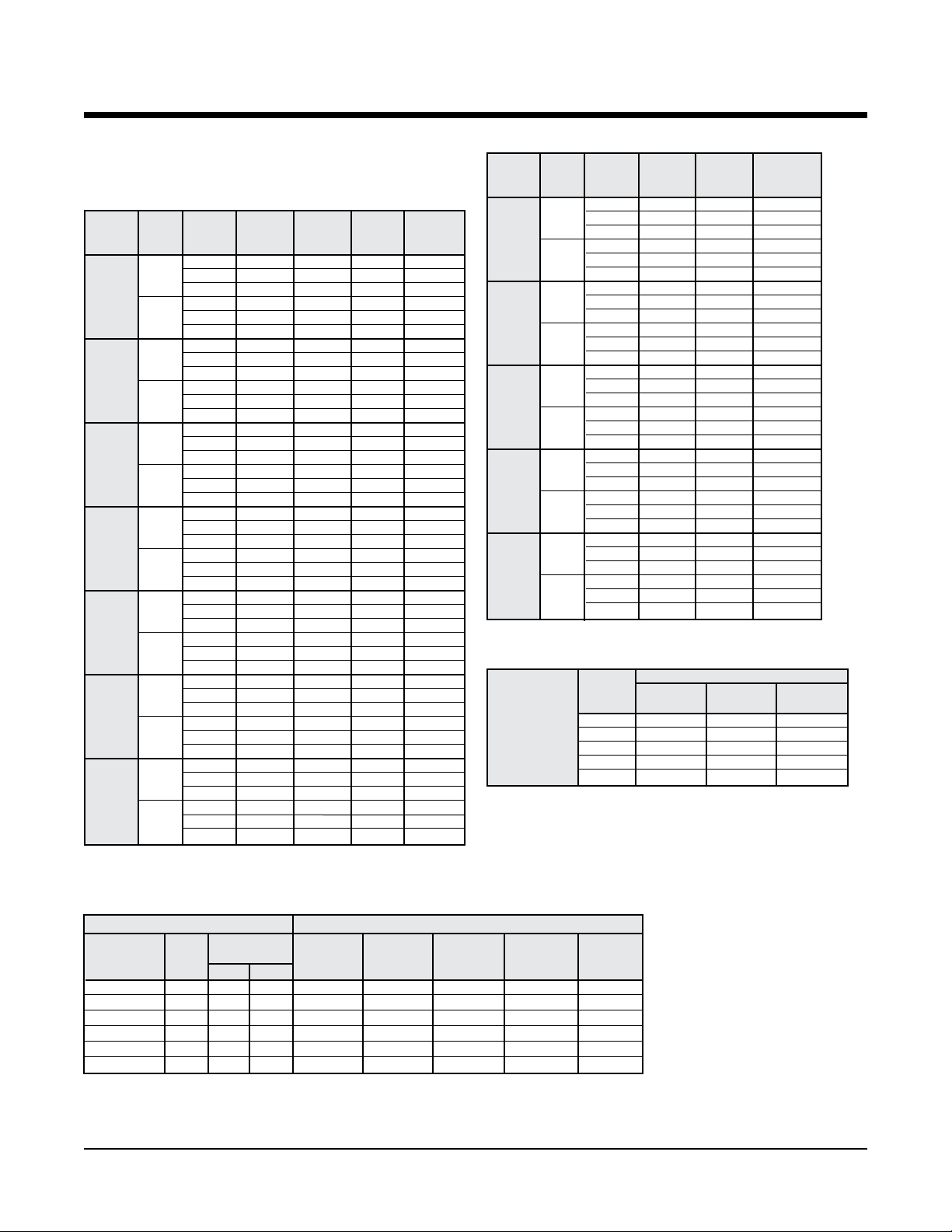
Capacity Data – RWD, RGD 420
Cooling capacities shown are gross capacities. For net capacities,
multiply blower bhp required times 2545 Btu per bph and subtract
from total and sensible in tables.
Table 19. Cooling
Total SH Heat
o
EWT(
F) gpm cfm Capacity Btu/h Watts Rejected
66
40
135
66
55
135
66
65
135
66
75
135
66
85
135
66
95
135
66
110
135
13,000 508,400 356,700 22,900 586,400
14,000 515,500 367,100 22,900 593,700
15,000 521,000 379,400 23,000 599,600
13,000 522,000 360,300 21,300 594,700
14,000 529,000 372,800 21,400 601,900
15,000 535,100 385,000 21,500 608,300
13,000 488,500 346,000 25,500 575,400
14,000 494,200 358,200 25,600 581,500
15,000 499,100 370,100 25,700 586,800
13,000 502,000 351,600 23,700 582,900
14,000 508,200 364,200 23,800 589,400
15,000 513,700 376,200 23,900 595,200
13,000 473,600 339,700 27,600 567,700
14,000 478,700 351,800 27,700 573,200
15,000 483,200 363,500 27,800 578,000
13,000 487,200 345,500 25,600 574,700
14,000 493,000 357,800 25,700 580,800
15,000 498,100 369,700 25,800 586,200
13,000 456,400 335,600 30,200 559,300
14,000 460,900 347,700 30,300 564,200
15,000 466,400 361,000 30,400 570,200
13,000 471,500 338,900 27,900 566,700
14,000 476,800 351,000 28,000 576,400
15,000 480,600 364,400 28,100 576,400
13,000 439,000 328,500 33,000 551,700
14,000 444,300 337,800 32,900 556,700
15,000 448,100 353,200 33,200 561,600
13,000 453,900 333,400 30,500 558,100
14,000 458,500 345,500 30,600 572,200
15,000 464,800 357,200 30,700 569,500
13,000 420,100 321,100 36,400 544,300
14,000 424,900 333,700 36,400 549,300
15,000 429,300 342,800 36,300 553,300
13,000 435,000 326,800 33,700 550,000
14,000 440,400 340,200 33,800 570,800
15,000 444,300 351,500 33,800 559,800
13,000 390,100 309,000 42,200 534,200
14,000 392,700 320,000 42,300 537,100
15,000 394,900 330,800 42,400 539,500
13,000 405,500 315,500 39,200 539,400
14,000 408,800 326,700 39,300 530,700
15,000 411,700 337,700 39,400 546,100
Btu/h Btu/h
Table 19c. Heating
Heating Heat
o
EWT(
F) gpm cfm Capacity Watts Absorpted
66
30
135
66
40
135
66
55
135
66
70
135
66
80
135
13,000 334,800 29,600 233,600
14,000 335,600 29,200 236,000
15,000 336,400 28,800 238,000
13,000 354,800 30,300 251,600
14,000 355,600 29,800 254,000
15,000 356,300 29,400 256,100
13,000 381,500 31,000 275,700
14,000 381,900 30,500 277,900
15,000 382,200 30,000 279,800
13,000 405,700 31,800 297,000
14,000 406,100 31,300 299,400
15,000 406,500 30,800 301,500
13,000 453,600 33,400 339,600
14,000 453,800 32,700 342,200
15,000 454,100 32,100 344,400
13,000 484,500 34,400 367,000
14,000 485,300 33,700 370,300
15,000 486,000 33,100 373,200
13,000 525,900 35,900 403,300
14,000 527,400 35,100 407,700
15,000 528,500 34,400 411,200
13,000 559,000 37,100 432,200
14,000 562,100 36,300 432,800
15,000 564,700 35,600 443,400
13,000 569,800 38,300 439,200
14,000 572,700 36,600 447,700
15,000 575,300 35,900 452,900
13,000 599,500 38,700 467,400
14,000 605,500 37,800 465,200
15,000 610,500 37,000 484,200
Btu/h Btu/h
Table 19d. Heating Correction Multipliers
Heating
Correction
Multipliers 60 1.014 1.038 0.925
Various 65 1.007 1.019 0.963
Entering Air oF 70 1 1 1
dbt Temperature 75 0.993 0.981 1.077
80 0.986 0.961 ––
Ent. Air
Heating Heat of Total
o
F dbt
Btu/h Absorp. Watts
Multipliers
Table 19b. Cooling Performance Correction Factors
Condenser Water Flow Cooling Performance Correction Factors
Cooling Pressure Total Heat Sensible
Cycle gpm
Design ∆T psi Ft.HD. Btu/h
8o 135 17 39.9 1.005 0.987 1.002 1.001 1.02
10o 108 12 26.7 1.000 1.000 1.000 1.000 1.00
12
14
16
20
o
90 8 19.3 0.987 1.012 0.992 0.996 0.98
o
75 6 13.9 0.973 1.025 0.985 0.992 0.95
o
66 5 11.0 0.960 1.037 0.977 0.988 0.93
o
54 3 7.7 0.958 1.054 0.973 0.980 0.91
Drop
Capacity
Watts
Rejection Capacity EER
Input
Btu/h Btu/h
Notes:
1. Above ratings are based on 80
wbt entering air in cooling, 70oF dbt in
heating. For other entering air conditions
see correction factor charts.
2. Above ratings do not include allowance
for water pump power consumption.
3. Heating ratings below 45
on the use of 20% methanol/water anti-
freeze.
4. Interpolation of ratings is permitted.
5. Above ratings are at 208 volts.
o
F dbt, 67oF
o
EWT based
Page 22 of 62 Rooftop Water Source Heat Pumps Catalog 1110
Page 24
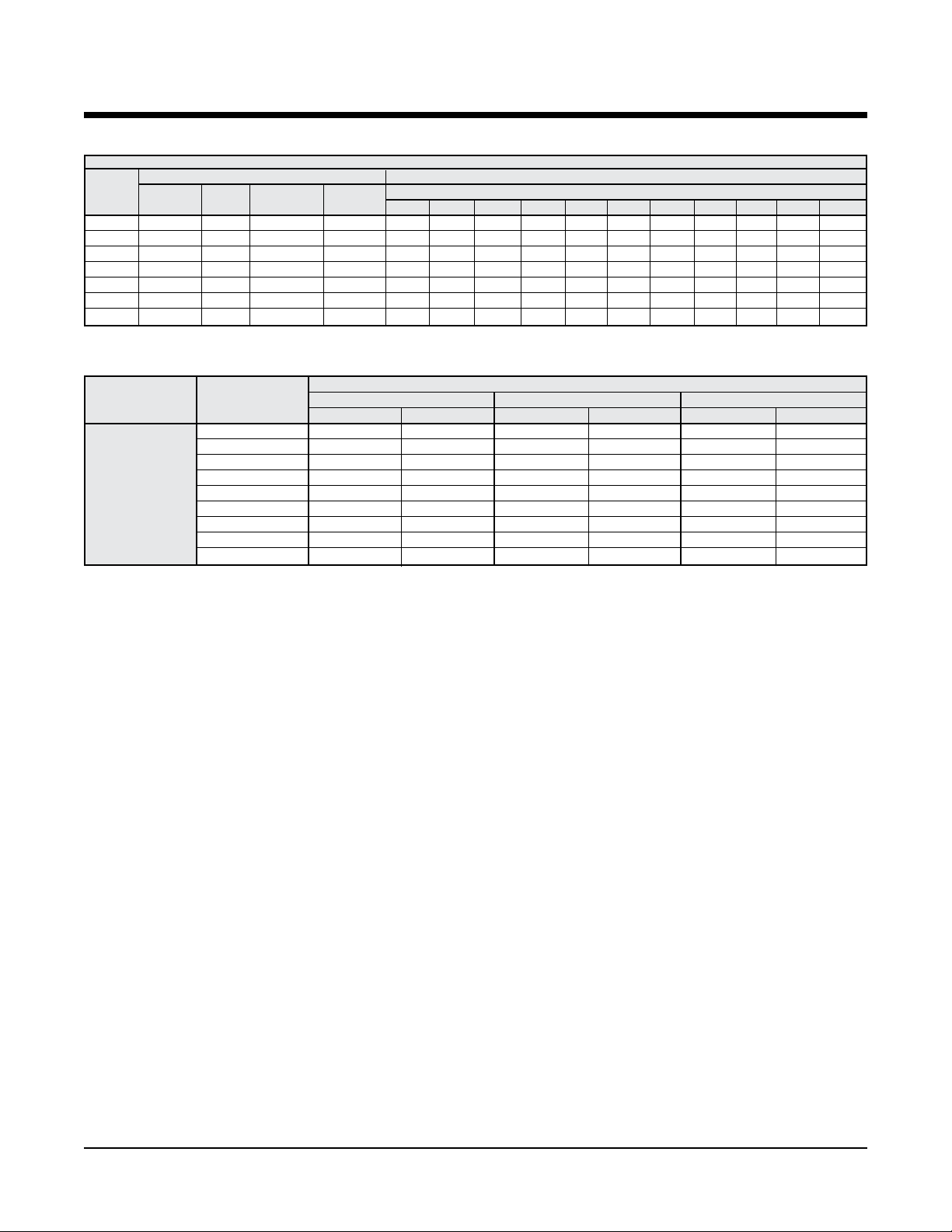
Correction Factors – RWD, RGD 036 – 420
Table 20. Cooling Correction Multipliers
Cooling Correction Multipliers – At Various Entering Air oF dbt and oF wbt
Ent. Air Multipliers Multipliers for Sensible Cooling
o
F Total
wbt Cooling
61 0.911 0.93 0.983 0.927 0.83 0.91 1.00 1.09 1.18 — — — — — —
63 0.938 0.95 0.989 0.949 0.74 0.83 0.91 1.00 1.09 1.18 — — — — —
65 0.968 0.97 0.994 0.973 0.65 0.74 0.83 0.91 1.00 1.09 1.18 1.27 — — —
67 1.000 1.00 1.000 1.000 0.56 0.65 0.73 0.82 0.91 1.00 1.09 1.18 1.27 — —
69 1.035 1.03 1.007 1.029 — 0.56 0.65 0.73 0.82 0.91 1.00 1.08 1.17 1.26 —
71 1.072 1.06 1.012 1.060 — — 0.56 0.64 0.73 0.82 0.9 0 0.99 1.08 1.17 1.26
73 1.108 1.09 1.019 1.092 — — — — 0.64 0.72 0.81 0.90 0.99 1.07 1.16
Table 21. Supplemental Electric Heaters
VOLTAGE
ARRANGEMENT UNIT SIZE 208
HEATER kW FLA HEATER kW FLA HEATER kW FLA
036 – 420 3.8 10.4 5.0 12.1 5.0 12.0
048 – 420 11.3 31.2 15.0 36.1 15.0 18.0
096 – 420 15.0 41.6 20.0 48.1 20.0 24.1
DOWNFLOW 096 – 420 18.8 52.0 25.0 60.1 25.0 30.1
096 – 420 22.5 62.5 30.0 72.2 30.0 36.1
120 – 420 26.3 72.9 35.0 84.2 35.0 42.1
120 – 420 30.0 83.3 40.0 96.2 40.0 48.1
180 – 420 37.5 104.1 50.0 120.3 50.0 60.1
180 – 420 45.0 124.9 60.0 144.3 60.0 72.2
EER Total Watts Heat Rej.
70 72 74 76 78 80 82 84 86 88 90
/60/3 240/60/3 480/60/3
At Entering Air oF dbt
Minimum circuit ampacity (MCA) for wire sizing
For units less supplemental electric heat: Use values from tables on pages 9 and 10.
For supplemental electric heat: Optional separate power supply for the electric heater. For the electric heater, MCA =
1.25 x heater amps.
For unit with supplemental electric heat: Single point power. In this case, the electric heater can operate simultane-
ously with the compressor(s).
Minimum circuit ampacity = [(Largest comp. RLA + electric heater amps) x 1.25 + FLA of all other motors and compressors]
Maximum fuse size
For units less supplemental electric heat: Use values from tables on pages 9 and 10.
For supplemental electric heat: Optional separate power supply for the electric heater. For the electric heater, MFS =
1.25 x heater amps.
For unit with supplemntal electric heat: Single point power. In this case, the electric heater can operate simultaneously
with the compressor(s).
Max. fuse size = (2.25 x compressor RLA) + FLA of all other motors and compressors + electric heater amps
Select the next smaller from the following standard fuse sizes: 15, 20, 25, 30, 35, 40, 45, 50, 60, 70, 80, 90, 100, 110, 125,
150, 175, 200, 225, 250, and 300.
Note: in some instances with relatively large electric heat loads, the value computed for maximum fuse size will be less than
the minimum circuit ampacity. In this situation, the maximum fuse size is the same as minimum circuit ampacity or the next
higher fuse size.
Catalog 1110 Rooftop Water Source Heat Pumps Page 23 of 62
Page 25

Physical Data – RWD, RGD 036 – 420
Physical Data – English Units
Table 22.
036 048 060 072 096 120 150 180 240 300 360 420
Fan Qty. 1 1 1 1 2 2 2 2 2 2 2 2
Fan Size (in) 9 X 6 9 X 9 10 X 10 11 X 10 12 X 9 12 X 9 12 X 9 15 X 11 15 X 11 15 X 15 15 X 15 15 X 15
Fan Motor Power (hp)
Small 1/2 3/4 3/4 1 1 1
Medium 3/4 1 1 1
Large 1 1
Coil Face Area
(sq. ft.)
Coil Rows 3 3 3 4 4 4 4 4 4 4 4 4
Condensate Size
MPT (Quantity)
Compressor (Qty.) Recip. (1) Recip. (1) Scroll (1) Scroll (1) Scroll (2) Scroll (2) Scroll (2) Scroll (2) Scroll (2) Scroll (2) Scroll (2) Scroll (3)
Water Conns.,
O.D.S. (in)
Filter Qty. 1 1 1 1 4 4 5 5 5 8 8 8
Filter Size (in) 28 x 30 x 2
Oper. Wt. (lbs.) 550 575 600 610 1125 1175 1630 1670 1800 2650 3450 3700
Ship Wt. (lbs.) 560 585 610 620 1145 1195 1670 1710 1840 2700 3500 3750
Curb Wt. (lbs.) 84 84 84 84 122 122 167 167 200 167 330 330
UNIT SIZE
DATA
1
/
11/
2
1
1
/
4.2 5.1 6.4 6.4 8.0 8.0 14.6 14.6 14.6 20.6 26.0 29.2
3/4" (1) 3/4" (1) 3/4" (1) 3/4" (1) 1" (2) 1" (2) 1" (2) 1" (2) 1" (2) 1" (2) 1" (2) 1" (2)
7/8" 1
1
/8"
11/
2
11/8"
2
32 x 32 x 2
/
2 2 3 3 5 71/2 10 –– ––
11/8" 15/8" 15/8" 15/8" 15/8" 15/8" 21/8" 21/8" 21/8"
11/
2
2
14 x 25 x 2
2 2 3 5 71/
2
2 –– 5 71/2 10
15 x 305/8 x 2
2
20 x 25 x 2
10 15
20 x 30 x 2
Physical Data – SI Units
Table 22b.
DATA
036 048 060 072 096 120 150 180 240 300 360 420
Fan Qty. 1 1 1 1 2 2 2 2 2 2 2 2
Fan Size (mm) 229 x 153 229 x 229 254 x 254 280 x 254 305 x 229 305 x 229 305 x 229 381 x 280 381 x 280 381 x 381 381 x 381 381 x 381
Fan Motor Power (watts)
Small 373 560 560 746 746 1119 1119 1492 –– 3730 5595 7460
Medium 560 746 746 1119 1119 1492 1492 2238 3730 5595 7460 11186
Large 746 1119 1119 1492 1492 2238 2238 3730 5595 7460 –– ––
Coil Face Area
(sq. m.)
0.39 0.48 0.60 0.60 0.75 0.75 1.36 1.36 1.36 1.92 2.42 2.72
Coil Rows 3 3 3 4 4 4 4 4 4 4 4 4
Condensate Size
(MPT) (Quantity)
19.1 (1) 19.1 (1) 19.1 (1) 19.1 (1) 25.4 (2) 25.4 (2) 25.4 (2) 25.4 (2) 25.4 (2) 25.4 (2) 25.4 (2)
Compressor Qty. Recip. (1) Recip. (1) Scroll (1) Scroll (1) Scroll (2) Scroll (2) Scroll (2) Scroll (2) Scroll (2) Scroll (2) Scroll (2) Scroll (3)
Water Conns., O.D.
(mm)
Filter Qty. 1 1 1 1 4 4 5 5 5 8 8 8
Filter Size (mm) 711 x 762 x 51
653 839 839 839 1212 1212 1212 1212 1212 1585 1585 1585
813 x 813 x 51
356 x 635 x 51
Oper. Wt. (kg) 250 261 272 277 511 533 740 758 817 1202 1565 1679
Ship Wt. (kg) 254 266 277 281 520 542 758 776 835 1225 1588 1701
Curb Wt. (kg) 38 38 38 38 56 56 76 76 91 76 150 150
UNIT SIZE
381 x 778 x 51
508 x 635 x 51
25.4 (2)
508 x 762 x 51
Page 24 of 62 Rooftop Water Source Heat Pumps Catalog 1110
Page 26

Fan Motor Performance Data – RWD, RGD 036 – 420
English Units
Table 23.
UNIT SIZE CFM
1,000 1,115 .4 1,200 .4 1,295 .5 1,385 .5 1,455 .6 1,530 .6 1,600 .7
036 1,200 1,150 .5 1,250 .5 1,340 .6 1,440 .6 1,500 .7 1,580 .7 1,650 .8
1,300 1,220 .5 1,320 .6 1,400 .7 1,470 .7 1,540 .8 1,620 .9 1,690 .9
1,700 1,290 .7 1,370 .7 1,450 .8 1,530 .9 1,600 1.0 1,680 1.1 1,750 1.2
048 1,800 1,330 .8 1,420 .8 1,490 1.0 1,570 1.1 1,650 1.1 1,710 1.2 1,800 1.4
1,900 1,390 .9 1,460 1.0 1,540 1.1 1,610 1.2 1,680 1.2 1,760 1.4 1,840 1.5
1,800 910 .6 995 .7 1,080 .8 1,165 .9 1,245 .9 1,320 1.0 1,390 1.1
060 2,000 970 .7 1,045 .8 1,125 .9 1,200 1.0 1,275 1.1 1,345 1.2 1,410 1.3
2,200 1,040 .8 1,140 .9 1,200 1.0 1,260 1.1 1,340 1.2 1,400 1.4 1,570 1.5
2,000 1,122 .8 1,182 .9 1,239 1.0 1,293 1.1 1,345 1.1 1,395 1.2 1,443 1.3
072 2,300 1,164 1.1 1,222 1.1 1,277 1.2 1,330 1.3 1,381 1.4 1,430 1.5 1,477 1.6
2,600 1,209 1.3 1,265 1.4 1,318 1.5 1,370 1.6 1,419 1.7 1,467 1.8 1,513 1.9
2,800 870 .8 960 1.0 1,030 1.1 1,090 1.3 1,160 1.4 1,230 1.6 1,290 1.8
096 3,200 910 1.1 1,000 1.2 1,060 1.4 1,130 1.6 1,200 1.8 1,270 1.9 1,320 2.2
3,600 970 1.4 1,040 1.5 1,080 1.7 1,170 1.8 1,210 2.0 - - - -
3,500 1,104 1.4 1,181 1.5 1,301 1.7 1,328 1.9 1,399 2.2 1,467 2.4 1,535 2.6
120 4,000 1,188 1.8 1,257 2.0 1,325 2.2 1,392 2.4 1,456 2.7 1,519 2.9 - -
4,500 1,271 2.4 1,335 2.6 1,397 2.8 1,458 3.0 - - - - - -
4,500 704 1.2 765 1.4 823 1.6 860 1.8 900 2.2 955 2.4 1,000 2.5
150 5,000 743 1.5 800 1.7 854 2.0 907 2.2 957 2.5 990 2.8 1,020 2.9
5,500 783 1.9 836 2.1 887 2.3 936 2.9 984 2.9 - - - -
5,500 760 1.9 800 2.0 840 2.2 890 2.4 950 2.7 1,000 2.9 1,050 3.2
180 6,000 790 2.3 830 2.5 870 2.8 920 3.0 970 3.3 1,020 3.5 1,070 3.8
6,500 830 2.7 880 2.9 920 3.2 960 3.5 1,020 3.8 1,060 4.0 1,100 4.3
7,000 860 3.2 910 3.5 950 3.8 1,000 4.1 1,040 4.4 1,080 4.7 1,120 5.0
240 8,000 920 4.1 960 4.4 1,000 4.8 1,050 5.1 1,090 5.5 1,130 5.8 1,170 6.2
9,000 980 5.2 1,020 5.6 1,050 6.0 1,080 6.5 1,140 6.7 1,170 7.1 - -
9,000 800 3.5 840 3.9 890 4.2 930 4.7 980 5.0 1,020 5.6 1,050 6.0
300 10,000 850 4.6 890 5.1 940 5.6 980 6.1 1,020 6.6 1,060 7.1 1,100 7.6
11,000 900 6.0 940 6.5 990 7.0 1,030 7.3 1,070 7.7 1,110 8.2 1,150 8.7
11,000 840 5.5 880 5.9 920 6.4 970 6.9 1,010 7.3 1,050 7.7 1,090 8.1
360 12,000 900 6.8 940 7.3 980 7.8 1,030 8.3 1,070 8.8 1,100 9.3 1,150 9.8
13,000 940 8.1 980 8.6 1,020 9.2 1,060 9.7 - - - - - -
13,000 930 7.6 960 8.1 1,000 8.6 1,040 9.2 1,070 9.5 1,120 10.0 1,060 11.0
420 14,000 980 9.4 1,030 9.7 1,060 10.5 1,090 11.0 1,130 11.6 1,170 12.0 1,190 13.0
0.4 0.6 0.8 1.0 1.2 1.4 1.6
RPM BHP RPM BHP RPM BHP RPM BHP RPM BHP RPM BHP RPM BHP
15,000 1,040 11.3 1,070 12.0 1,110 12.5 1,140 13.1 1,170 13.5 1,210 14.0 1,240 15.0
EXTERNAL STATIC PRESSURE (INCHES W.C.)
Notes: 1. For units with electric heat, add 0.1 inch external static pressure prior to making rpm and Bhp selection.
2. Tables can be interpolated but not extrapolated.
3.Aboveexternalstaticpressurevaluesinclude1"throwawaylters.
“S” Models – Italic
“M” Models – Regular
“L” Models – Bold Italic
Catalog 1110 Rooftop Water Source Heat Pumps Page 25 of 62
Page 27

Dimensional Data – RWD, RGD 036 – 072
Downow unit
Note 1
Add 6" for 25% outside air intake
and13"foreconomizerhoods
Roof curb RWD 036 - 072
Page 26 of 62 Rooftop Water Source Heat Pumps Catalog 1110
Page 28

Dimensional Data – RWD, RGD 096 – 120
Downow unit
Note 1
Add 6" for 25% outside air intake
and13"foreconomizerhoods
Roof curb RWD 096 - 120
Catalog 1110 Rooftop Water Source Heat Pumps Page 27 of 62
Page 29

Dimensional Data – RWD, RGD 150 – 240
Downow unit
Note 1
Add 6" for 25% outside air intake
and19"foreconomizerhoods
Roof curb RWD 150 - 240
Page 28 of 62 Rooftop Water Source Heat Pumps Catalog 1110
Page 30

Dimensional Data – RWD, RGD 300 – 360
Downow unit
Note 1
Add 6" for 25% outside air intake
and17"foreconomizerhoods
Roof curb RWD 300 - 360
Model
300 56"
360 66"
Height
Catalog 1110 Rooftop Water Source Heat Pumps Page 29 of 62
Page 31

Dimensional Data – RWD, RGD 420
Downow unit
Note 1
Add 6" for 25% outside air intake
and13"foreconomizerhoods
Roof curb RWD 420
Page 30 of 62 Rooftop Water Source Heat Pumps Catalog 1110
Page 32

Engineering Guide Specications – RWD, RGD
General
Furnish and install McQuay Model RWD Series water
source heat pump per plans and specications. Capacity and energy efciency shall not be less than scheduled.
Unit shall be provided with factory installed options listed
below. Performance ratings shall be per ARI Standard ISO
13256-1.
Approvals
Unit shall be design certied to conform to appropriate
UL/ANSI Standards by ETL or other nationally recognized
testing laboratory.
Cabinet
Cabinet shall be constructed of G-90 galvanized steel with
gauge thickness of: Bases - 16-gauge; Corner Posts and
Tops - 18-gauge; Access Panels - 20-gauge. The interior of
the indoor airside is to be thermally insulated with 1-inch
thick - 11/2-pound density glass ber insulation. A closed
cell neoprene liner shall be installed on the underside of
the base pan for noise reduction and weather seal to the
roof curb. The cabinet shall be mounted on two steel rails
to facilitate installation. The design of the cabinet shall
allow access to the compressor and electrical panel without
impairing unit operation.
Sloped Stainless Steel Condensate
Drain Pan
The condensate drain pan shall be sloped to comply with
ASHRAE Standard 62-1089R and fabricated from stainless
steel. The bottom shall be insulated with 5/8" closed cell
neoprene insulation. Condensation may be drained from
either side of the unit (model sizes 096 through 420) from
MPT drain ttings positioned at the exterior of each side of
the cabinet.
Non Rust Base
Unit base pan shall be coated with viscous petroleum distillate to a uniform 1/4" wet depth, air dried, and cured to
form a solid protective layer to eliminate corrosive oxidation.
Paint Finish
Constructed of hot dipped galvanized G-90 steel that is
chemically treated with zinc phosphate, coated with 0.2 to
0.3 MIL polyurethane primer then nished with 0.7 to 0.8
MIL polyester top coat. Finish shall meet or exceed 1,000
hour Salt Spray Test per ASTM B117-97.
Non-Corroding Hardware
All exterior hardware nuts, bolts, and washers shall be
stainless steel (Type 304). All exterior screws shall be steel
coated with Magnigard Silver 17.
Assembly and Test
The unit shall be completely factory assembled, wired,
thoroughly leak and safety control tested. After assembly,
each unit shall be charged and run tested in both the heating
and cooling cycles.
Refrigerant System
The refrigerant system shall include a reciprocating compressor in model 036 and 048 or scroll compressors in
models 060 and larger, with a crankcase heater and thermal
overload protection. The compressor shall rest on external
rubber isolators.
Each system shall include a reversing valve accumulator,
dual gauge connections for high and low pressure readings,
bi-ow thermostatic expansion valve with inner copper
tube and outer steel tube, and copper tube aluminum plate-
nned indoor air coil.
Safety controls shall include low-pressure manual reset
safety system. Unit shall include a compressor logic control
module with a circuit to lock compressor off in the event
one of the safety controls have been activated. Unit shall include a circuit to bypass the 30/15 psig low pressure cutout
at start-up for 90 seconds. Unit shall not be restarted until
the room thermostat has been turned off and then on again
or electric power to the unit has been
interrupted.
Electrical
Internally wired controls shall include the compressor
control module(s) and the blower and compressor motor contactors or starters. The 24-volt control circuit shall
include a transformer and low voltage terminal board for
external thermostat control hookup.
Fan Section
A forward curved, statically and dynamically balanced
DWDI centrifugal blower(s) shall be used. Both the
blower(s) and housing(s) are to be galvanized steel. The
blower wheel(s) shall be mounted on a solid steel shaft sup-
ported by sealed ball bearings. The shaft shall be driven by
adjustable belt drive sheaves connected to a nominal 1725rpm motor with sealed ball bearings. The sealed bearings
on both the blower shaft and motor shall be permanently
lubricated.
Catalog 1110 Rooftop Water Source Heat Pumps Page 31 of 62
Page 33

Design Features – RWH, RGH
Model RWH, RGH –
High Efciency Rooftop
Horizontal Discharge
RWH 060
Application
The model RWH water source heat pump air conditioner
is designed to be efcient in both the heating and cooling
cycles. Model RGH is designed for cooling only applications.
These platform mounted units can be installed alongside
the building or on the roof where horizontal air supply and
return are required. They are frequently used for remodel
projects and those buildings where the duct work cannot be
routed inside the building. They are not generally used in
curb mounted applications.
After assembly, each unit is charged and run tested in both
the heating and cooling cycles for reliable operation.
The RWH model is normally used with a water loop
system utilizing a cooling tower and boiler. These units
are designed to operate with an entering water temperature
between 55oF and 95oF. The RGH model is rated for a
ground loop heat exchanger application with an entering
uid temperature between 30oF and 100oF in accordance
with ARI Standard ISO 13256-1.
Paint Finish
The unit is constructed of hot dipped galvanized G-90 steel
that is chemically treated with zinc phosphate, coated with
0.2 to 0.3 MIL polyurethane primer then nished with 0.7
to 0.8 MIL polyester top coat, these attractive units are suitable for a variety of applications. Finish meets or exceeds a
1,000 hour Salt Spray Test per ASTM B117-97.
Non-rust Sound Attenuating Base Pan
Unit base pans are fabricated from 16-gauge G-90 galva-
nized steel which is lled with viscous petroleum distillate
to a uniform 1/4" wet depth, air dried, and cured to form a
solid protective layer to resist corrosive oxidation.
Air handling sections have an additional layer of 24-gauge
aluminum that covers and encapsulates the corrosion protection. Units have a layer of 3/8" thick closed cell insulation on the bottom of the base to provide thermal insulation,
sound attenuation and curb perimeter seal.
Non-Corroding Hardware
Exterior nuts, bolts and washers are stainless steel. Exterior
screws are steel coated with Magnigard Silver 17, an epoxy
nish containing aluminum ake pigment that meets or
exceeds a 10,000 hour Salt Spray Test per ASTM B117-97.
Compressor
Models 036 and 048 are equipped with high efciency
reciprocating compressors. Models 060 and larger are
equipped with scroll compressors selected for their reliabil-
ity and high efciency. Compressor mountings are designed
to reduce vibration transmission to the unit structure and
minimize piping stress.
Compressor Protection
All compressors have crankcase heat and internal overheat
protection.
Standard Design Features
Heavy Duty Cabinet
All models are constructed of G-90 galvanized steel. Bases
are 16-gauge, corner posts are 18-gauge, access panels are
20-gauge and top pans are 18-gauge. The interior of the en-
tire unit is thermally insulated with 1-inch thick berglass
with an R value of 4.2. Insulation surface exposed to the air
stream is nished with an acrylic coating that is resistant to
air erosion. The design of the cabinet allows access to the
electrical panel without impairing unit operation.
Page 32 of 62 Rooftop Water Source Heat Pumps Catalog 1110
Page 34

Design Features – RWH, RGH
Compressor Control Module
The sequence begins with a three second start delay, a
ninety second bypass of low pressure cutout switch at start-
up, and a ve minute anti-short-cycle time delay (delay
begins upon opening of thermostat). Compressor operation
is locked out upon opening of high pressure cutout or low
pressure cutout (after 90 second start-up delay expires).
Units can be reset remotely at thermostat or by removing
and reapplying power to unit. Units can be switched to 24-
vac output for remote fault indication (eld option).
Separate Refrigeration Circuits
Multiple refrigeration circuits are standard on sizes 096
thru 420. Multicompressor models provide the added bene-
t of partial standby. Also, they provide two stage operation
with one compressor being activated from the rst stage
of the two stage space thermostat on the cooling cycle. On
the heating cycle, all compressors are activated by the rst
stage of the space thermostat.
Indoor Air Coil
The indoor air coils have aluminum ns formed on multiple
rows of seamless copper tubing arranged in a staggered
tube conguration. The tubes are mechanically expanded,
rmly bonding the tube to the collar of each n.
The Coaxial Water Coil
The Coaxial Water Coil consists of an enhanced surface
inner copper tube with outer steel tube (tube-in-tube). Field
piped return and supply water lines enter through individual
sleeves in the compressor base pan section after passing
through the roof curb. RGH models are equipped with
fully-insulated refrigerant and water lines and a polyurethane foam encased coaxial water coil.
Evaporator Blower and Motor
A forward-curved, statically and dynamically balanced
DWDI centrifugal blower(s) is used for the supply air.
Blower wheels are fabricated of galvanized steel. Blower
housings are fabricated of galvanized or epoxy coated steel.
The blower wheel(s) is mounted on a solid steel shaft supported by sealed ball bearings. The shaft is belt driven with
adjustable drive sheaves connected to a 1725 rpm motor
with sealed ball bearings. The sealed bearings on both the
blower shaft and motor are permanently lubricated. Motors
up to 3 horsepower are internally protected (autoreset) and
motors 5 horsepower and larger are externally protected
(manual reset).
Refrigerant Circuit
Included in each refrigerant circuit is a reversing valve,
high pressure unit protection control, low pressure unit
protection control/loss of charge protector, dual gauge con-
nections for high and low pressure readings, and a bi-ow
thermo-expansion valve. The expansion valve has adjustable superheat and distributors to meter the refrigerant
evenly to the evaporator refrigerant circuits. The 24-volt
reversing valve is energized in the cooling mode, making it
fail safe to the heating mode.
Factory-installed service ports in compressor suction, discharge and liquid lines are included for ease of servicing. A
common refrigerant line connection is also provided for use
with water regulating valves.
Electric Controls
Internally wired controls include the compressor control
module, heat relay, fan relay and the blower and compressor motor contactors or starters mounted in sheet metal
control panel. The isolated 24-volt control circuit includes
a transformer and low voltage terminal board for external
thermostat control hookup.
Catalog 1110 Rooftop Water Source Heat Pumps Page 33 of 62
Page 35
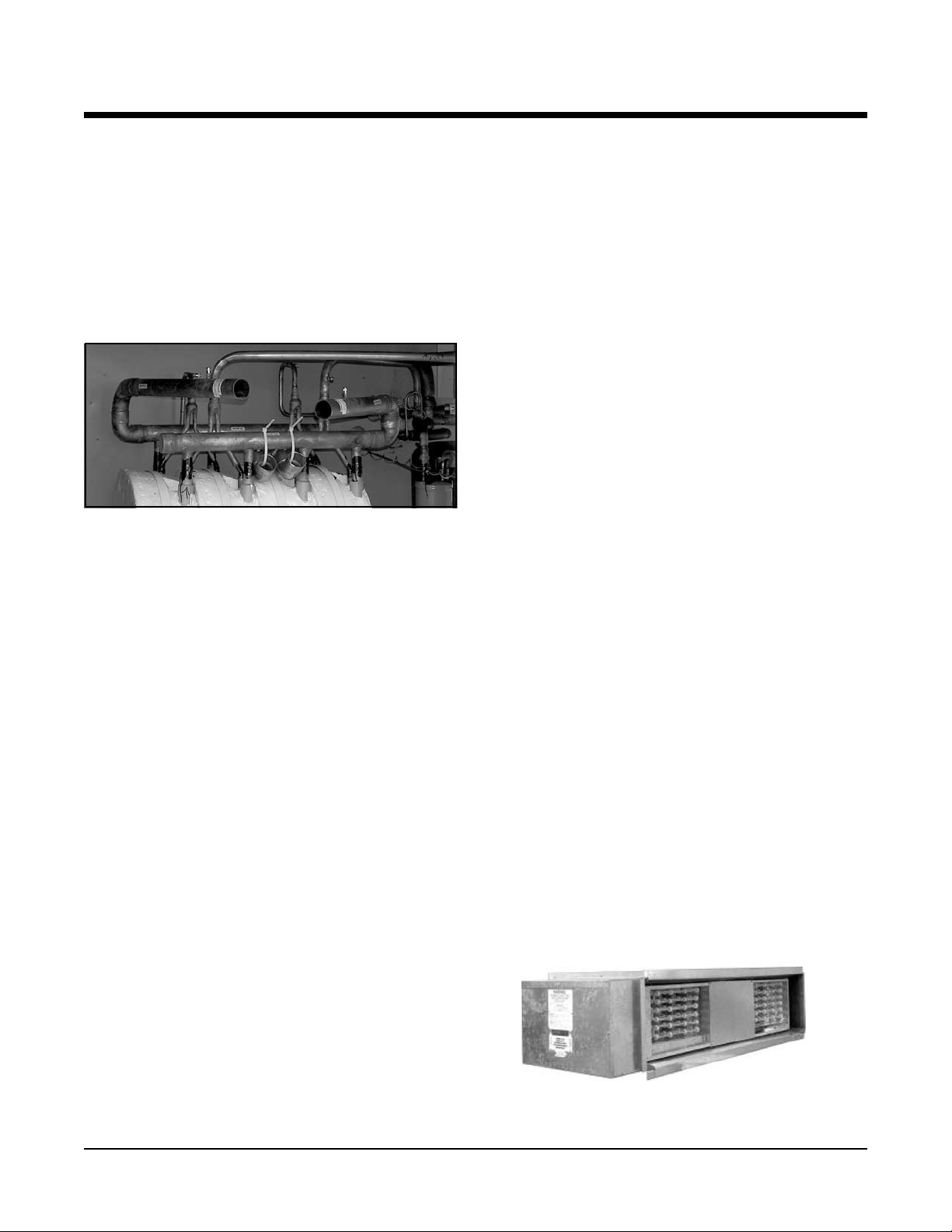
Design Features/Optional Features – RWH, RGH
Terminal Board Connections
Terminal boards are furnished for 24-volt thermostat connections on units.
Water Connections
Water connections are stubbed off inside the cabinet with
sleeves in the bottom pan for easy connection. Units are
shipped with water pressure taps and upper elbows for easy
connection to water source.
Water Connections Detail
Filters
Unit sizes 300 thru 420 are shipped with 2-inch thick
disposable glass ber media lters mounted in the factoryinstalled lter rack on the return air opening. Optionally
available are 2-inch deep pleat, or 2-inch aluminum metal
mesh lters. For sizes 036 thru 240 an accessory return air
lter box is available.
Electric Heaters
A wide range of electric heaters sizes are available for eld
installation in sizes 036 thru 240. Factory-installed heaters
are available in the sizes 300, 360 and 420.
Sloped Stainless Steel Condensate
Drain Pan
The condensate drain pan is sloped to comply with
ASHRAE Standard 62-1089R and fabricated from stainless
steel. The bottom is insulated with 5/8" closed cell neoprene insulation. The drain pan is furnished with MPT drain
ttings positioned at the exterior of the cabinet.
Refrigerant:
■ R-407C available.
Specialty Coils:
■ Cupro-nickel coaxial coil.
Motors:
■ Standard efciency motor.
■ High efciency motor.
Filters:
■ 2-inch aluminum metal media lters.
■ 2-inch extended surface cleanable lters.
Electrical Options:
■ Clogged lter indicator.
■ 115-volt GFCI convenience outlet with 15A circuit
breaker.
■ Non-fused disconnect NEMA3R enclosure.
Refrigerant Circuit Components &
Controls:
■ Lead Compressor Waste Heat Recovery Water Heater.
■ Hot gas bypass (single compressor units or lead only
on dual compressor units).
■ Hot gas reheat (one row coil).
Supplemental Heat Options:
■ Electric Heat (see accessories).
Controls:
■ 24-volt with terminal strip.
■ Microprocessor.
Outdoor Air Ventilation:
■ Manual economizer.
■ Motorized 2-position outside air/return air damper.
■ Modulating economizer with barometric relief.
Optional Features RWH, RGH
Corrosion Protection Options
■ Seacoast Construction.
Coil Coatings:
■ Baked Phenolic.
Page 34 of 62 Rooftop Water Source Heat Pumps Catalog 1110
Supplemental Electric Heater
Page 36

ISO Performance Data – RWH (Water Loop)
Horizontal Discharge Units
Table 24.
UNIT AIRFLOW WATER FLOW COOLING HEATING
SIZE
CFM L
208-230/60/3
036 1200 566 8.6 0.54 460/60/3 34,500 10,104 14.1 42,900 12,565 4.4
380/415/50/3
208-230/60/3
048 1800 850 13.0 0.82 460/60/3 49,600 14,526 13.0 59,600 17,455 4.5
380/415/50/3
208-230/60/3
060 2000 944 15.5 0.98 460/60/3 60,600 17,748 12.8 73,000 21,380 4.6
380/415/50/3
208-230/60/3
072 2300 1086 18.0 1.14 460/60/3 75,200 22,024 12.8 83,300 24,397 4.6
380/415/50/3
208-230/60/3
096 3200 1510 24.0 1.52 460/60/3 95,000 27,823 12.5 173,000 33,095 4.2
380/415/50/3
208-230/60/3
120 4000 1888 31.0 1.96 460/60/3 119,000 34,852 12.0 140,000 41,003 4.2
380/415/50/3
208-230/60/3
150 5000 2360 36.0 2.27 460/60/3 150,700 44,136 12.5 185,000 54,182 4.3
380/415/50/3
208-230/60/3
180 6000 2832 42.0 2.65 460/60/3 171,900 50,345 13.9 208,000 60,918 4.6
380/415/50/3
208-230/60/3
240 8000 3776 58.0 3.66 460/60/3 229,800 67,303 12.5 287,100 84,085 4.3
380/415/50/3
208-230/60/3
300 10,000 4720 68.0 4.29 460/60/3 276,400 80,951 13.6 343,100 100,486 4.6
380/415/50/3
208-230/60/3
360 12,000 5663 93.0 5.87 460/60/3 376,500 110,267 12.4 459,100 134,459 4.2
380/415/50/3
208-230/60/3
420 14,000 6607 108.0 6.81 460/60/3 426,700 124,970 12.1 550,000 161,081 4.2
380/415/50/3
Notes:
EER=EnergyEfciencyRatio;COP=CoefcientofPerformance.
Cooling capacity is based on 80.6oF (27oC) db, 66.2oF (19oC) wb entering air temperature and 86oF (30oC) entering, 95oF (35oC) leaving water temperature. Heating
capacity based on 68oF (20oC) db entering air temperature and 68oF (20oC)enteringwatertemperature.Netcapacitiesincludefanmotorheat;50cycle unitsare
derated, 60 cycle units.
/s GPM L/s
VOLTAGE
BTU
/HR WATTS EER BTU/HR WATTS COP
Catalog 1110 Rooftop Water Source Heat Pumps Page 35 of 62
Page 37

ISO Performance Data – RGH (Ground Loop)
Horizontal Discharge Units
Table 25.
UNIT AIRFLOW WATER FLOW COOLING HEATING
SIZE
CFM L
208-230/60/3
036 1200 566 8.6 0.54 460/60/3 38,500 11,276 14.9 24,100 7,058 3.5
380/415/50/3
208-230/60/3
048 1800 850 13.0 0.82 460/60/3 52,000 15,230 14.9 35,000 10,251 3.5
380/415/50/3
208-230/60/3
060 2000 944 15.5 0.98 460/60/3 60,200 17,631 14.1 47,000 13,756 3.2
380/415/50/3
208-230/60/3
072 2300 1086 18.0 1.14 460/60/3 75,300 22,346 15.9 55,400 16,225 3.7
380/415/50/3
208-230/60/3
096 3200 1510 24.0 1.52 460/60/3 96,000 28,116 13.5 71,400 20,911 3.2
380/415/50/3
208-230/60/3
120 4000 1888 31.0 1.96 460/60/3 120,000 35,145 13.4 93,100 27,267 3.2
380/415/50/3
208-230/60/3
150 5000 2360 36.0 2.27 460/60/3 154,000 45,103 13.6 120,500 35,291 3.2
380/415/50/3
208-230/60/3
180 6000 2832 42.0 2.65 460/60/3 178,200 52,190 15.7 133,600 39,128 3.5
380/415/50/3
208-230/60/3
240 8000 3776 58.0 3.66 460/60/3 236,900 69,382 14.5 180,600 52,893 3.4
380/415/50/3
208-230/60/3
300 10,000 4720 68.0 4.29 460/60/3 285,000 83,469 14.8 230,000 67,361 3.6
380/415/50/3
208-230/60/3
360 12,000 5663 93.0 5.87 460/60/3 383,100 112,200 14.0 304,100 89,063 3.2
380/415/50/3
208-230/60/3
420 14,000 6607 108.0 6.81 460/60/3 440,000 128,865 13.4 369,000 108,071 3.2
380/415/50/3
/s GPM L/s
VOLTAGE
BTU
/HR WATTS EER BTU/HR WATTS COP
Notes:
EER=EnergyEfciencyRatio;COP=CoefcientofPerformance.
Cooling capacity is based on 80.6oF (27oC) db, 66.2oF (19oC) wb entering air temperature and 77oF (25oC) entering, 87oF (31oC) leaving water temperature. Heating
capacity based on 68oF (20oC) db entering air temperature and 32oF (0oC)entering watertemperature. Netcapacities includefanmotorheat;50 cycleunits are
derated, 60 cycle units.
Page 36 of 62 Rooftop Water Source Heat Pumps Catalog 1110
Page 38
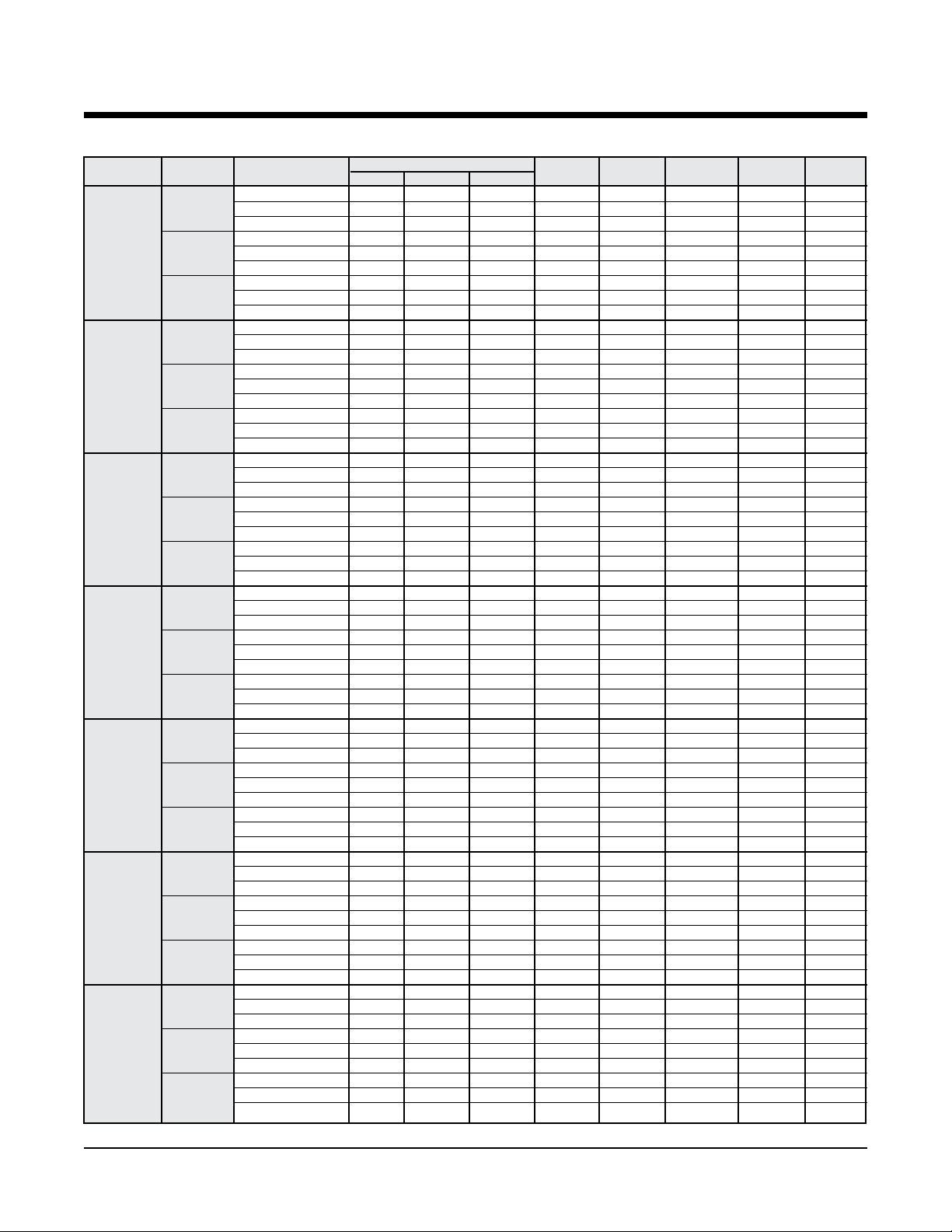
Electrical Data – RWH, RGH 036 – 150
Table 26. Horizontal Discharge Units
HP Qty RLA (each) LRA (each) FLA Amps Volts Ampacity Size
208-230/60/3 1 8.7 68.0 2.8 11.5 197/253 13.7 20
1/2 460/60/3 1 4.8 36.0 1.4 6.2 414/506 7.4 15
380/50/3 1 4.8 36.0 1.2 6.0 342/420 7.2 15
208-230/60/3 1 8.7 68.0 2.8 11.5 197/253 13.7 20
036 3/4 460/60/3 1 4.8 36.0 1.4 6.2 414/506 7.4 15
380/50/3 1 4.8 36.0 2.1 6.9 342/420 8.1 15
208-230/60/3 1 8.7 68.0 3.4 12.1 197/253 14.3 20
1 460/60/3 1 4.8 36.0 1.7 7.5 414/506 7.7 15
380/50/3 1 4.8 36.0 1.9 6.7 342/420 7.9 15
208-230/60/3 1 12.8 91.0 2.8 15.6 197/253 18.8 30
3/4 460/60/3 1 5.8 42.0 1.4 7.2 414/506 8.7 15
380/50/3 1 5.8 42.0 2.1 7.9 342/420 9.4 15
208-230/60/3 1 12.8 91.0 3.4 16.2 197/253 19.4 30
048 1 460/60/3 1 5.8 42.0 1.7 7.5 414/506 8.9 15
380/50/3 1 5.8 42.0 1.9 7.7 342/420 9.2 15
208-230/60/3 1 12.8 91.0 4.6 17.4 197/253 20.6 30
1
380/50/3 1 5.8 42.0 2.7 8.5 342/420 9.9 15
208-230/60/3 1 17.4 123.0 2.8 20.2 197/253 24.6 40
3/4 460/60/3 1 6.8 49.5 1.4 8.2 414/506 9.9 15
380/50/3 1 6.8 49.5 2.1 8.9 342/420 10.6 15
208-230/60/3 1 17.4 124.0 3.4 20.8 197/253 25.2 40
060 1 460/60/3 1 6.8 59.6 1.7 8.5 414/506 10.2 15
380/50/3 1 6.8 59.6 1.9 8.7 342/420 10.4 15
208-230/60/3 1 17.4 124.0 4.6 22.0 197/253 26.4 40
1
380/50/3 1 6.8 59.6 2.7 9.5 342/420 11.2 15
208-230/60/3 1 20.0 156.0 3.4 23.4 197/253 28.4 45
1 460/60/3 1 9.0 75.0 1.7 10.7 414/506 12.9 20
380/50/3 1 9.0 75.0 1.9 10.9 342/420 13.2 20
208-230/60/3 1 20.0 156.0 4.6 24.6 197/253 29.6 45
072 11/2 460/60/3 1 9.0 75.0 2.3 11.3 414/506 13.6 20
380/50/3 1 9.0 75.0 2.7 11.7 342/420 13.9 20
208-230/60/3 1 20.0 156.0 6.2 26.2 197/253 31.2 50
2 460/60/3 1 9.0 75.0 3.1 12.1 414/506 14.4 20
380/50/3 1 9.0 75.0 3.5 12.5 342/420 14.8 20
208-230/60/3 2 12.9 93.0 3.4 29.2 197/253 32.4 45
1 460/60/3 2 6.5 46.5 1.7 14.7 414/506 16.3 20
380/50/3 2 6.5 46.5 1.9 14.9 342/420 16.5 20
208-230/60/3 2 12.9 91.0 4.6 30.4 197/253 33.6 45
096 11/2 460/60/3 2 6.5 46.0 2.3 15.3 414/506 16.9 20
380/50/3 2 6.5 46.0 2.7 15.7 342/420 17.3 20
208-230/60/3 2 12.9 91.0 6.2 32.0 197/253 35.2 45
2 460/60/3 2 6.5 46.0 3.1 15.5 414/506 17.7 20
380/50/3 2 6.5 46.0 3.5 15.9 342/420 18.1 20
208-230/60/3 2 16.1 125.0 4.6 36.8 197/253 40.8 50
1
380/50/3 2 8.1 66.5 2.7 18.9 342/420 20.9 25
208-230/60/3 2 16.1 128.0 6.2 38.4 197/253 42.4 50
120 2 460/60/3 2 8.1 63.0 3.1 19.3 414/506 21.3 25
380/50/3 2 8.1 63.0 3.5 19.7 342/420 21.7 25
208-230/60/3 2 16.1 128.0 8.0 40.2 197/253 44.2 60
3 460/60/3 2 8.1 63.0 4.0 20.2 414/506 22.2 30
380/50/3 2 8.1 63.0 4.8 21.0 342/420 23.0 30
208-230/60/3 2 20.0 156.0 4.6 44.6 197/253 49.6 60
1
380/50/3 2 9.0 75.5 2.7 20.7 342/420 23.0 30
208-230/60/3 2 20.0 156.0 6.2 46.2 197/253 51.2 70
150 2 460/60/3 2 9.0 75.5 3.1 21.1 414/506 23.4 30
380/50/3 2 9.0 75.5 3.5 21.5 342/420 23.8 30
208-230/60/3 2 20.0 156.0 8.0 48.0 197/253 53.0 70
3 460/60/3 2 9.0 75.5 4.0 22.0 414/506 24.3 30
380/50/3 2 9.0 75.5 4.8 22.8 342/420 25.1 30
Unit Size
Fan Motor
1
/2 460/60/3 1 5.8 42.0 2.3 8.1 414/506 9.6 15
1
/2 460/60/3 1 6.8 59.6 2.3 9.1 414/506 10.8 15
1
/2 460/60/3 2 8.1 66.5 2.3 18.5 414/506 20.5 25
1
/2 460/60/3 2 9.0 75.5 2.3 20.3 414/506 22.6 30
Compressor
Voltage
Fan Motor Total Unit Min./Max. Min. Circuit Max Fuse
Catalog 1110 Rooftop Water Source Heat Pumps Page 37 of 62
Page 39

Electrical Data – RWH, RGH 180 – 420
Table 26. Horizontal Discharge Units (Cont'd)
208-230/60/3 2 22.5 164.0 6.2 51.2 197/253 56.8 70
2 460/60/3 2 10.9 100.0 3.1 24.9 414/506 27.6 35
380/50/3 2 10.9 100.0 3.5 25.3 342/420 28.0 35
208-230/60/3 2 22.5 164.0 8.0 53.0 197/253 58.6 80
180 3 460/60/3 2 10.9 100.0 4.0 25.8 414/506 28.5 35
380/50/3 2 10.9 100.0 4.8 26.6 342/420 29.3 40
208-230/60/3 2 22.5 164.0 13.4 58.4 197/253 64.0 80
5 460/60/3 2 10.9 100.0 6.7 28.5 414/506 31.2 40
380/50/3 2 10.9 100.0 7.8 29.6 342/420 32.3 40
208-230/60/3 2 30.9 225.0 13.4 75.2 197/253 82.9 110
5 460/60/3 2 15.6 114.0 6.7 37.9 414/506 41.8 50
240 380/50/3 2 15.6 114.0 7.8 39.0 342/420 42.9 50
208-230/60/3 2 30.9 225.0 20.0 81.8 197/253 89.5 110
7
380/50/3 2 15.6 114.0 11.5 42.7 342/420 46.6 60
208-230/60/3 2 37.8 239.0 13.4 89.0 197/253 98.5 125
5 460/60/3 2 17.3 125.0 6.7 41.3 414/506 45.6 60
380/50/3 2 17.3 125.0 7.8 42.4 342/420 46.7 60
208-230/60/3 2 37.8 239.0 20.0 95.6 197/253 105.1 125
300 7
380/50/3 2 17.3 125.0 11.5 46.1 342/420 50.4 60
208-230/60/3 2 37.8 239.0 28.0 103.6 197/253 113.1 150
10 460/60/3 2 17.3 125.0 14.0 48.6 414/506 52.9 70
380/50/3 2 17.3 125.0 14.0 48.6 342/420 52.9 70
208-230/60/3 2 52.6 425.0 20.0 125.2 197/253 138.4 175
7
360 380/50/3 2 23.8 187.0 11.5 59.1 342/420 65.1 80
208-230/60/3 2 52.6 425.0 28.0 133.2 197/253 146.4 175
10 460/60/3 2 23.8 187.0 14.0 61.6 414/506 67.5 90
380/50/3 2 23.8 187.0 14.0 61.6 342/420 67.5 90
208-230/60/3 3 37.8 239.0 28.0 141.4 197/253 150.9 175
10 460/60/3 3 17.3 125.0 14.0 65.9 414/506 70.2 80
420 380/50/3 3 17.3 125.0 14.0 65.9 342/420 70.2 80
208-230/60/3 3 37.8 239.0 38.6 152.0 197/253 161.5 175
15 460/60/3 3 17.3 125.0 19.3 71.2 414/506 75.5 90
380/50/3 3 17.3 125.0 19.3 71.2 342/420 75.5 90
Unit Size
Fan Motor
HP Qty RLA (each) LRA (each) FLA Amps Volts Ampacity Size
1
/2 460/60/3 2 15.6 114.0 10.0 41.2 414/506 45.1 60
1
/2 460/60/3 2 17.3 125.0 10.0 44.6 414/506 48.9 60
1
/2 460/60/3 2 23.8 187.0 10.0 57.6 414/506 63.6 80
Compressor
Voltage
Fan Motor Total Unit Min./Max. Min. Circuit Max Fuse
Page 38 of 62 Rooftop Water Source Heat Pumps Catalog 1110
Page 40

Capacity Data – RWH, RGH 036
Cooling capacities shown are gross capacities. For net capacities,
multiply blower bhp required times 2545 Btu per bph and subtract
from total and sensible in tables.
Table 27. Cooling
Total SH Heat
o
EWT(
F) gpm cfm Capacity Btu/h Watts Rejected
1,100 45,810 32,040 1,230 50,000
6.1 1,200 46,490 33,490 1,230 50,700
40 1,300 47,100 34,850 1,240 51,330
1,100 46,460 32,310 1,120 50,280
8.6 1,200 47,180 33,740 1,120 51,020
1,300 47,780 35,180 1,130 51,630
1,100 43,990 31,450 1,490 49,080
6.1 1,200 44,680 32,780 1,490 49,780
1,300 45,170 34,280 1,500 50,310
1,100 44,330 31,590 1,440 49,260
50 7.2 1,200 45,030 32,920 1,450 49,970
1,300 45,590 34,320 1,450 50,550
1,100 44,680 31,620 1,400 49,450
8.6 1,200 45,340 33,070 1,400 50,130
1,300 45,920 34,450 1,410 50,720
1,100 40,340 29,790 1,940 46,970
6.1 1,200 40,860 31,240 1,950 47,520
1,300 41,510 32,650 1,960 48,210
1,100 40,610 30,040 1,910 47,130
70 7.2 1,200 41,230 31,310 1,910 47,760
1,300 41,850 32,800 1,920 48,430
1,100 40,900 30,150 1,880 47,310
8.6 1,200 41,530 31,440 1,880 47,950
1,300 42,160 32,930 1,890 48,620
1,100 34,860 27,750 2,090 41,990
6.1 1,200 35,310 29,140 2,100 42,480
1,300 35,750 30,370 2,110 42,940
1,100 35,140 27,860 2,060 42,180
85 7.2 1,200 35,610 29,260 2,070 42,680
1,300 36,010 30,610 2,080 43,110
1,100 35,440 27,870 2,030 42,380
8.6 1,200 35,870 29,360 2,040 42,850
1,300 36,290 30,720 2,050 43,290
1,100 32,030 26,500 2,340 40,030
6.1 1,200 32,420 27,860 2,350 40,460
1,300 32,720 29,300 2,360 40,790
1,100 32,300 26,610 2,320 40,220
100 7.2 1,200 32,700 27,970 2,330 40,660
1,300 33,010 29,420 2,340 41,000
1,100 32,550 26,710 2,300 40,400
8.6 1,200 32,960 28,060 2,310 40,850
1,300 33,270 29,520 2,320 41,190
1,100 30,040 25,710 2,490 38,560
6.1 1,200 30,340 27,200 2,510 38,900
1,300 30,660 28,450 2,520 39,260
1,100 30,300 25,810 2,480 38,760
110 7.2 1,200 30,610 27,300 2,490 39,100
1,300 30,900 28,640 2,500 39,450
1,100 30,540 25,910 2,460 38,930
8.6 1,200 30,850 27,400 2,470 39,290
1,300 31,160 28,900 2,480 39,630
Btu/h Btu/h
Heating Heat
o
EWT(
F) gpm cfm Capacity Watts Absorpted
1,100 20,860 1,450 15,900
6.1 1,200 20,890 1,410 16,060
30 1,300 20,910 1,380 16,200
1,100 21.490 1,490 16,410
8.6 1,200 21,520 1,450 16,580
1,300 21,550 1,410 16,730
1,100 25,310 1,650 19,670
6.1 1,200 25,350 1,610 19,870
40 1,300 25,370 1,560 20,040
1,100 26,090 1,690 20,320
8.6 1,200 26,140 1,640 20,540
1,300 26,170 1,600 20,720
1,100 30,200 1,910 23,700
6.1 1,200 30,280 1,850 23,950
1,300 30,320 1,800 24,160
1,100 30,710 1,930 24,130
50 7.2 1,200 30,790 1,870 24,390
1,300 30,840 1,830 24,610
1,100 31,170 1,950 24,520
8.6 1,200 31,260 1,900 24,790
1,300 31,320 1,850 25,020
1,100 35,180 2,130 27,900
6.1 1,200 35,310 2,080 28,220
1,300 35,400 2,030 28,490
1,100 35,760 2,160 28,390
60 7.2 1,200 35,900 2,100 28,720
1,300 36,010 2,050 29,000
1,100 36,290 2,180 28,840
8.6 1,200 36,450 2,130 29,180
1,300 36,570 2,080 29,470
1,100 40,030 2,320 32,090
6.1 1,200 40,240 2,270 32,490
1,300 40,410 2,220 32,820
1,100 40,690 2,350 32,650
70 7.2 1,200 40,930 2,300 33,060
1,300 41,110 2,260 33,410
1,100 41,340 2,390 33,200
8.6 1,200 41,600 2,340 33,620
1,300 41,800 2,290 33,980
1,100 45,170 2,550 36,450
6.1 1,200 45,500 2,510 36,940
1,300 45,770 2,460 37,350
1,100 45,960 2,590 37,120
80 7.2 1,200 46,320 2,550 37,630
1,300 46,610 2,500 38,060
1,100 46,660 2,620 37,720
8.6 1,200 47,060 2,580 38,250
1,300 47,370 2,540 38,700
Btu/h Btu/h
Table 27d. Heating Correction Multipliers
Heating
Correction
Multipliers 60 1.014 1.038 0.925
Various 65 1.007 1.019 0.963
Entering Air oF 70 1 1 1
dbt Temperature 75 0.993 0.981 1.077
80 0.986 0.961 ––
Ent. Air
Heating Heat of Total
o
F dbt
Btu/h Absorp. Watts
Multipliers
Table 27b. Cooling Performance Correction Factors
Table 27c. Heating
Condenser Water Flow Cooling Performance Correction Factors
Cooling Pressure Total Heat Sensible
Cycle gpm
Design ∆T psi Ft.HD. Btu/h
8o 10.6 7.2 16.6 1.005 0.987 1.002 1.001 1.02
10o 8.6 4.7 10.9 1.000 1.000 1.000 1.000 1.00
12
14
16
20
o
7.1 3.1 7.2 0.987 1.012 0.992 0.996 0.98
o
6.1 2.3 5.4 0.973 1.025 0.985 0.992 0.95
o
5.3 2.0 4.6 0.960 1.037 0.977 0.988 0.93
o
4.3 1.2 2.8 0.958 1.054 0.973 0.980 0.91
Drop
Capacity
Watts
Rejection Capacity EER
Input
Btu/h Btu/h
Notes:
1. Above ratings are based on 80
wbt entering air in cooling, 70oF dbt in
heating. For other entering air conditions
see correction factor charts.
2. Above ratings do not include allowance
for water pump power consumption.
3. Heating ratings below 45
on the use of 20% methanol/water anti-
freeze.
4. Interpolation of ratings is permitted.
5. Above ratings are at 208 volts.
o
F dbt, 67oF
o
EWT based
1110 Rooftop Water Source Heat Pumps Page 39 of 62
Page 41

Capacity Data – RWH, RGH 048
Table 28c. Heating
Cooling capacities shown are gross capacities. For net capacities,
multiply blower bhp required times 2545 Btu per bph and subtract
from total and sensible in tables.
Table 28. Cooling
Total SH Heat
o
EWT(
F) gpm cfm Capacity Btu/h Watts Rejected
1,700 64,590 46,720 2,230 72,200
8.5 1,800 65,270 47,840 2,230 72,880
40 1,900 65,640 49,320 2,240 73,290
1,700 65,590 47,110 2,130 72,840
13 1,800 66,280 48,260 2,130 73,540
1,900 66,810 49,540 2,130 74,080
1,700 62,230 45,660 2,470 70,670
8.5 1,800 62,820 46,860 2,480 71,270
1,900 63,230 48,230 2,490 71,710
1,700 62,850 45,850 2,410 71,080
50 10.5 1,800 63,420 47,100 2,420 71,660
1,900 63,760 48,600 2,430 72,040
1,700 63,270 45,970 2,370 71,360
13 1,800 63,820 47,270 2,380 71,930
1,900 64,180 48,760 2,390 72,320
1,700 56,940 43,710 2,980 67,120
8.5 1,800 57,420 44,940 2,990 67,620
1,900 58,060 46,220 3,000 68,290
1,700 57,500 43,920 2,930 67,500
70 10.5 1,800 58,070 45,010 2,930 68,080
1,900 58,620 46,480 2,950 68,670
1,700 57,890 44,030 2,890 67,770
13 1,800 58,330 45,390 2,900 68,230
1,900 58,910 46,830 2,910 68,840
1,700 51,270 41,280 3,110 69,530
8.5 1,800 51,590 42,740 3,130 62,260
1,900 51,960 43,980 3,140 62,670
1,700 51,700 41,710 3,070 62,170
85 10.5 1,800 52,140 42,940 3,080 62,640
1,900 52,520 44,190 3,090 63,060
1,700 52,060 41,840 3,040 62,420
13 1,800 52,600 42,900 3,040 62,980
1,900 52,900 44,330 3,050 63,320
1,700 47,130 39,590 3,470 58,980
8.5 1,800 47,390 41,060 3,490 59,300
1,900 47,760 42,180 3,500 59,700
1,700 47,630 39,800 3,430 59,330
100 10.5 1,800 47,910 41,250 3,450 59,680
1,900 48,240 42,520 3,460 60,050
1,700 47,880 40,150 3,410 59,500
13 1,800 48,350 41,180 3,410 60,000
1,900 48,590 42,640 3,430 60,290
1,700 44,150 38,650 3,710 56,830
8.5 1,800 44,530 39,760 3,720 57,240
1,900 44,760 41,130 3,740 57,530
1,700 44,720 38,630 3,670 57,240
110 10.5 1,800 44,970 40,110 3,690 57,560
1,900 45,260 41,330 3,700 57,900
1,700 45,040 38,770 3,640 57,480
13 1,800 45,300 40,240 3,660 57,800
1,900 45,600 41,470 3,680 58,150
Btu/h Btu/h
Table 28b. Cooling Performance Correction Factors
Condenser Water Flow Cooling Performance Correction Factors
Cooling Pressure Total Heat Sensible
Cycle gpm Drop Capacity
Design ∆T psi Ft.HD. Btu/h
8o 15.7 8.5 19.7 1.005 0.987 1.002 1.001 1.02
10o 13 5.9 13.7 1.000 1.000 1.000 1.000 1.00
12
14
16
20
o
10.4 3.9 9.0 0.987 1.012 0.992 0.996 0.98
o
8.9 2.9 6.7 0.973 1.025 0.985 0.992 0.95
o
7.8 2.2 5.2 0.960 1.037 0.977 0.988 0.93
o
6.3 1.5 3.4 0.958 1.054 0.973 0.980 0.91
Watts
Rejection Capacity EER
Input
Btu/h Btu/h
Page 40 of 62 Rooftop Water Source Heat Pumps 1110
Heating Heat
o
EWT(
F) gpm cfm Capacity Watts Absorpted
1,700 32,000 2,270 24,260
8.5 1,800 32,040 2,250 24,350
30 1,900 32,170 2,250 24,490
1,700 32,920 2,300 25,080
13 1,800 33,020 2,290 25,210
1,900 33,110 2,280 25,330
1,700 37,770 2,480 29,300
8.5 1,800 37,890 2,470 29,470
40 1,900 37,990 2,460 29,610
1,700 38,950 2,520 30,340
13 1,800 39,070 2,510 30,520
1,900 39,190 2,500 30,670
1,700 43,880 2,700 34,680
8.5 1,800 44,020 2,680 34,890
1,900 44,150 2,660 35,070
1,700 44,660 2,720 35,370
50 10.5 1,800 44,820 2,700 35,590
1,900 44,960 2,690 35,790
1,700 45,230 2,740 35,870
13 1,800 45,390 2,720 36,100
1,900 45,540 2,710 36,300
1,700 50,260 2,910 40,310
8.5 1,800 50,440 2,890 40,580
1,900 50,600 2,870 40,820
1,700 51,190 2,950 41,130
60 10.5 1,800 51,390 2,920 41,410
1,900 51,590 2,900 41,690
1,700 51,870 2,970 41,730
13 1,800 52,100 2,940 42,060
1,900 52,280 2,920 42,320
1,700 56,890 3,150 46,150
8.5 1,800 57,110 3,120 46,480
1,900 57,310 3,090 46,780
1,700 58,010 3,190 47,140
70 10.5 1,800 58,250 3,150 47,500
1,900 58,470 3,120 47,810
1,700 58,790 3,210 47,840
13 1,800 59,050 3,180 48,210
1,900 59,270 3,150 48,540
1,700 63,680 3,380 52,150
8.5 1,800 63,960 3,340 52,570
1,900 64,210 3,300 52,950
1,700 64,970 3,420 53,290
80 10.5 1,800 65,270 3,380 53,740
1,900 65,540 3,340 54,140
1,700 65,820 3,450 54,040
13 1,800 66,140 3,410 54,510
1,900 66,410 3,370 54,930
Table 28d. Heating Correction Multipliers
Heating
Correction
Multipliers 60 1.014 1.038 0.925
Various 65 1.007 1.019 0.963
Entering Air oF 70 1 1 1
dbt Temperature 75 0.993 0.981 1.077
80 0.986 0.961 ––
Ent. Air
o
F dbt
Btu/h Btu/h
Heating Heat of Total
Btu/h Absorp. Watts
Notes:
1. Above ratings are based on 80
2. Above ratings do not include allowance
3. Heating ratings below 45
4. Interpolation of ratings is permitted.
5. Above ratings are at 208 volts.
Multipliers
wbt entering air in cooling, 70oF dbt in
heating. For other entering air conditions
see correction factor charts.
for water pump power consumption.
on the use of 20% methanol/water anti-
freeze.
o
F dbt, 67oF
o
EWT based
Page 42

Capacity Data – RWH, RGH 060
Table 29c. Heating
Cooling capacities shown are gross capacities. For net capacities,
multiply blower bhp required times 2545 Btu per bph and subtract
from total and sensible in tables.
Table 29. Cooling
Total SH Heat
o
EWT(
F) gpm cfm Capacity Btu/h Watts Rejected
11
40
15.5
11
50 13
15.5
11
70 13
15.5
11
85 13
15.5
11
100 13
15.5
11
110 13
15.5
1,800 75,430 52,770 2,640 84,430
2,000 76,660 55,660 2,650 85,710
2,200 77,680 58,510 2,670 86,780
1,800 76,030 53,070 2,560 84,780
2,000 77,330 55,950 2,580 86,120
2,200 78,370 58,840 2,590 87,220
1,800 73,490 51,990 2,860 83,240
2,000 74,700 54,860 2,870 84,500
2,200 75,670 57,720 2,890 85,520
1,800 73,850 52,140 2,820 83,450
2,000 75,070 55,010 2,830 84,730
2,200 76,060 57,870 2,840 85,760
1,800 74,160 52,270 2,780 83,640
2,000 75,400 55,140 2,790 84,930
2,200 76,400 58,000 2,810 85,970
1,800 69,200 50,230 3,420 80,870
2,000 70,270 53,120 3,440 82,000
2,200 71,260 55,620 3,440 83,010
1,800 69,570 50,380 3,370 81,060
2,000 70,660 53,260 3,380 82,200
2,200 71,650 55,800 3,390 83,220
1,800 69,890 50,510 3,320 81,230
2,000 70,990 53,400 3,340 82,380
2,200 71,870 56,330 3,350 83,300
1,800 65,680 48,850 3,950 79,170
2,000 66,750 51,430 3,960 80,270
2,200 67,440 54,580 3,980 81,010
1,800 66,040 48,990 3,890 79,330
2,000 67,120 51,600 3,900 80,440
2,200 67,960 54,330 3,910 81,310
1,800 66,360 49,110 3,840 79,470
2,000 67,330 52,070 3,860 80,490
2,200 68,160 54,870 3,870 81,360
1,800 62,050 47,150 4,590 77,720
2,000 62,830 50,290 4,610 78,560
2,200 63,620 52,870 4,620 79,380
1,800 62,290 47,620 4,530 77,760
2,000 63,320 50,040 4,540 78,810
2,200 63,990 53,030 4,550 79,520
1,800 62,590 47,720 4,480 77,880
2,000 63,620 50,190 4,480 78,930
2,200 64,300 53,190 4,500 79,640
1,800 59,520 46,080 5,090 76,900
2,000 60,350 48,870 5,100 77,760
2,200 61,140 51,730 5,110 78,590
1,800 59,850 46,220 5,030 76,990
2,000 60,690 49,020 5,040 77,870
2,200 61,490 51,880 5,040 78,700
1,800 60,130 46,360 4,970 77,080
2,000 60,990 49,140 4,980 77,970
2,200 61,800 52,010 4,990 78,810
Btu/h Btu/h
Table 29b. Cooling Performance Correction Factors
Condenser Water Flow Cooling Performance Correction Factors
Cooling Pressure Total Heat Sensible
Cycle gpm Drop Capacity
Design ∆T psi Ft.HD. Btu/h
8o 19.4 10 21.9 1.005 0.987 1.002 1.001 1.02
10o 15.5 6 14.0 1.000 1.000 1.000 1.000 1.00
12
14
16
20
o
12.9 4 9.7 0.987 1.012 0.992 0.996 0.98
o
11.1 3 7.2 0.973 1.025 0.985 0.992 0.95
o
9.7 2 5.5 0.960 1.037 0.977 0.988 0.93
o
7.8 2 3.5 0.958 1.054 0.973 0.980 0.91
Watts
Rejection Capacity EER
Input
Btu/h Btu/h
1110 Rooftop Water Source Heat Pumps Page 41 of 62
Heating Heat
o
EWT(
F) gpm cfm Capacity Watts Absorpted
Btu/h Btu/h
11
30
15.5
11
40
15.5
11
50 13
15.5
11
60 13
15.5
11
70 13
15.5
11
80 13
15.5
1,800 42,040 3,290 30,300
2,000 42,100 3,230 30,560
2,200 42,150 3,180 30,770
1,800 42,760 3,310 31,050
2,000 42,820 3,240 31,310
2,200 42,880 3,190 31,520
1,800 47,700 3,410 35,750
2,000 47,780 3,340 36,060
2,200 47,840 3,280 36,310
1,800 48,600 3,430 36,570
2,000 48,690 3,350 36,900
2,200 48,770 3,290 37,170
1,800 53,790 3,530 41,530
2,000 53,900 3,450 41,920
2,200 53,990 3,380 42,220
1,800 54,370 3,550 42,070
2,000 54,490 3,460 42,470
2,200 54,580 3,390 42,790
1,800 54,900 3,560 42,560
2,000 55,020 3,470 42,970
2,200 55,130 3,400 43,290
1,800 60,290 3,670 47,610
2,000 60,430 3,570 48,090
2,200 60,550 3,490 48,470
1,800 60,990 3,690 48,280
2,000 61,150 3,580 48,780
2,200 61,280 3,500 49,170
1,800 61,660 3,700 48,940
2,000 61,830 3,600 49,450
2,200 61,970 3,510 49,850
1,800 67,140 3,820 54,130
2,000 67,330 3,700 54,710
2,200 67,500 3,610 55,180
1,800 68,000 3,840 54,960
2,000 68,210 3,720 55,560
2,200 68,390 3,630 56,040
1,800 68,710 3,850 55,620
2,000 68,940 3,730 56,240
2,200 69,130 3,640 56,740
1,800 74,350 3,980 60,960
2,000 74,610 3,850 61,660
2,200 74,830 3,740 62,230
1,800 75,320 4,010 61,890
2,000 75,610 3,870 62,620
2,200 75,840 3,760 63,210
1,800 76,020 4,020 62,480
2,000 76,320 3,880 63,250
2,200 76,570 3,770 63,850
Table 29d. Heating Correction Multipliers
Heating
Correction
Multipliers 60 1.014 1.038 0.925
Various 65 1.007 1.019 0.963
Entering Air oF 70 1 1 1
dbt Temperature 75 0.993 0.981 1.077
80 0.986 0.961 ––
Ent. Air
Heating Heat of Total
o
F dbt
Btu/h Absorp. Watts
Notes:
1. Above ratings are based on 80
2. Above ratings do not include allowance
3. Heating ratings below 45
4. Interpolation of ratings is permitted.
5. Above ratings are at 208 volts.
Multipliers
67oF wbt entering air in cooling, 70oF dbt
in heating. For other entering air conditions
see correction factor charts.
for water pump power consumption.
on the use of 20% methanol/water anti-
freeze.
o
EWT based
o
F dbt,
Page 43

Capacity Data – RWH, RGH 072
Table 30c. Heating
Cooling capacities shown are gross capacities. For net capacities,
multiply blower bhp required times 2545 Btu per bph and subtract
from total and sensible in tables.
Table 30. Heating
Total SH Heat
o
EWT(
F) gpm cfm Capacity Btu/h Watts Rejected
12
40
18
12
50 15
18
12
70 15
18
12
85 15
18
12
100 15
18
12
110 15
18
2,000 82,960 56,110 4,040 96,760
2,300 84,830 60,300 4,100 98,820
2,600 86,310 64,280 4,140 100,440
2,000 83,800 56,630 3,930 97,210
2,300 85,720 60,850 3,990 99,330
2,600 87,350 64,650 4,020 101,080
2,000 80,460 55,360 4,350 95,310
2,300 82,390 59,270 4,390 97,380
2,600 83,940 62,950 4,420 99,040
2,000 81,010 55,590 4,280 95,620
2,300 83,060 59,350 4,320 97,790
2,600 84,370 63,550 4,360 99,240
2,000 81,370 55,740 4,230 95,820
2,300 83,370 59,660 4,280 97,950
2,600 84,790 63,690 4,310 99,500
2,000 75,490 53,100 5,040 92,700
2,300 77,090 57,230 5,080 94,430
2,600 78,590 61,260 5,120 96,040
2,000 75,940 53,470 4,970 92,890
2,300 77,670 57,420 5,000 94,740
2,600 79,190 61,480 5,030 96,370
2,000 76,290 53,610 4,920 93,070
2,300 78,050 57,550 4,950 94,950
2,600 79,580 61,630 4,980 96,580
2,000 71,480 51,440 5,690 90,880
2,300 73,110 55,200 5,710 92,610
2,600 74,400 59,450 5,750 94,030
2,000 72,000 51,630 5,600 91,100
2,300 73,650 55,430 5,630 92,840
2,600 75,110 59,370 5,650 94,400
2,000 72,320 51,800 5,540 91,230
2,300 73,840 55,910 5,570 92,860
2,600 75,320 59,860 5,600 94,430
2,000 67,260 49,820 6,490 89,390
2,300 68,960 53,570 6,510 91,190
2,600 70,180 57,260 6,540 92,490
2,000 67,760 49,980 6,390 89,550
2,300 69,330 54,110 6,420 91,220
2,600 70,560 57,840 6,440 92,540
2,000 68,090 50,080 6,320 89,660
2,300 69,810 53,920 6,340 91,450
2,600 71,060 57,640 6,370 92,780
2,000 64,400 48,640 7,120 88,710
2,300 65,900 52,660 7,160 90,320
2,600 67,060 56,340 7,190 91,580
2,000 65,010 48,500 7,010 88,920
2,300 66,540 52,530 7,040 90,550
2,600 67,530 56,640 7,080 91,680
2,000 65,170 48,950 6,950 88,870
2,300 66,700 53,010 6,970 90,490
2,600 67,870 56,720 6,990 91,740
Btu/h Btu/h
Table 30b. Cooling Performance Correction Factors
Condenser Water Flow Cooling Performance Correction Factors
Cooling Pressure Total Heat Sensible
Cycle gpm
Design ∆T psi Ft.HD. Btu/h
8o 23 5 12.0 1.006 0.988 1.003 1.003 1.02
10o 18 4 8.0 1.000 1.000 1.000 1.000 1.00
12
14
16
20
o
15 3 6.0 0.995 1.011 0.998 0.995 0.99
o
13 2 4.5 0.991 1.022 0.995 0.992 0.97
o
11 2 3.5 0.986 1.035 0.992 0.990 0.95
o
9 1 2.5 0.975 1.056 0.988 0.985 0.93
Drop
Capacity
Watts
Rejection Capacity EER
Input
Btu/h Btu/h
Page 42 of 62 Rooftop Water Source Heat Pumps 1110
Heating Heat
o
EWT(
F) gpm cfm Capacity Watts Absorpted
12
30
18
12
40
18
12
50 15
18
12
60 15
18
12
70 15
18
12
80 15
18
2,000 55,920 4,660 40,080
2,300 56,070 4,550 40,540
2,600 56,180 4,470 40,890
2,000 57,260 4,700 41,400
2,300 57,430 4,580 41,900
2,600 57,560 4,500 42,270
2,000 63,360 4,880 46,460
2,300 63,550 4,750 47,080
2,600 63,700 4,650 47,540
2,000 64,940 4,920 47,810
2,300 65,170 4,790 48,470
2,600 65,350 4,690 48,970
2,000 71,140 5,110 53,420
2,300 71,400 4,950 54,200
2,600 71,610 4,830 54,780
2,000 72,320 5,140 54,510
2,300 72,620 4,980 55,330
2,600 72,850 4,860 55,940
2,000 73,130 5,160 55,270
2,300 73,450 5,000 56,110
2,600 73,690 4,880 56,740
2,000 79,440 5,350 61,080
2,300 79,790 5,170 62,030
2,600 80,080 5,040 62,740
2,000 80,840 5,400 62,380
2,300 81,240 5,210 63,380
2,600 81,550 5,070 64,130
2,000 81,820 5,430 63,290
2,300 82,240 5,240 64,320
2,600 82,570 5,100 65,100
2,000 88,140 5,630 69,030
2,300 88,610 5,420 70,190
2,600 88,980 5,260 71,060
2,000 89,800 5,680 70,570
2,300 90,320 5,460 71,800
2,600 90,730 5,310 72,710
2,000 90,920 5,720 71,610
2,300 91,470 5,500 72,880
2,600 91,910 5,340 73,830
2,000 97,200 5,930 77,330
2,300 97,830 5,680 79,020
2,600 98,320 5,510 80,040
2,000 99,100 5,990 79,300
2,300 99,770 5,740 80,750
2,600 100,310 5,570 81,840
2,000 100,360 6,040 80,100
2,300 101,080 5,790 81,650
2,600 101,650 5,610 82,810
Btu/h Btu/h
Table 30d. Heating Correction Multipliers
Heating
Correction
Multipliers 60 1.014 1.038 0.925
Various 65 1.007 1.019 0.963
Entering Air oF 70 1 1 1
dbt Temperature 75 0.993 0.981 1.077
80 0.986 0.961 ––
Ent. Air
Heating Heat of Total
o
F dbt
Btu/h Absorp. Watts
Notes:
1. Above ratings are based on 80
2. Above ratings do not include allowance
3. Heating ratings below 45
4. Interpolation of ratings is permitted.
5. Above ratings are at 208 volts.
Multipliers
wbt entering air in cooling, 70oF dbt in
heating. For other entering air conditions
see correction factor charts.
for water pump power consumption.
on the use of 20% methanol/water anti-
freeze.
o
EWT based
o
F dbt, 67oF
Page 44

Capacity Data – RWH, RGH 096
Table 31c. Heating
Cooling capacities shown are gross capacities. For net capacities,
multiply blower bhp required times 2545 Btu per bph and subtract
from total and sensible in tables.
Table 31. Cooling
Total SH Heat
o
EWT(
F) gpm cfm Capacity Btu/h Watts Rejected
Btu/h Btu/h
16
40
24
16
50 20
24
16
70 20
24
16
85 20
24
16
100 20
24
16
110 20
24
2,800 114,590 80,400 4,200 121,750
3,200 116,920 85,710 4,230 124,130
3,600 118,900 90,560 4,240 126,140
2,800 115,980 80,980 4,050 122,890
3,200 118,500 86,120 4,070 125,450
3,600 120,450 91,150 4,090 127,430
2,800 111,350 78,800 4,580 119,160
3,200 113,560 84,090 4,610 121,420
3,600 115,180 89,420 4,630 123,090
2,800 112,060 79,340 4,490 119,710
3,200 114,360 84,570 4,510 122,050
3,600 116,200 89,550 4,530 123,920
2,800 112,600 79,560 4,420 120,150
3,200 114,950 84,780 4,440 122,530
3,600 116,810 89,780 4,460 124,420
2,800 104,180 76,040 5,540 113,630
3,200 106,150 81,300 5,560 115,640
3,600 108,290 86,360 5,580 117,810
2,800 104,980 76,330 5,420 114,230
3,200 106,990 81,600 5,450 116,290
3,600 109,130 86,750 5,460 118,450
2,800 105,510 76,520 5,350 114,630
3,200 107,550 81,800 5,370 116,710
3,600 109,680 87,010 5,390 118,870
2,800 98,620 73,800 6,410 109,550
3,200 100,580 78,690 6,430 111,550
3,600 102,520 83,940 6,460 113,540
2,800 99,390 74,070 6,290 110,110
3,200 101,200 79,360 6,310 111,960
3,600 103,180 84,620 6,330 113,990
2,800 99,890 74,260 6,210 110,480
3,200 101,730 79,540 6,230 112,350
3,600 103,720 84,830 6,250 114,380
2,800 92,840 71,510 7,420 105,490
3,200 95,040 76,610 7,440 107,730
3,600 96,580 81,350 7,460 109,310
2,800 93,570 71,770 7,290 106,000
3,200 95,630 77,260 7,310 108,110
3,600 97,350 81,690 7,330 109,850
2,800 94,050 71,940 7,200 106,330
3,200 96,120 77,450 7,230 108,450
3,600 97,700 82,260 7,240 110,060
2,800 88,950 69,820 8,160 102,860
3,200 90,930 75,230 8,190 104,900
3,600 92,320 80,050 8,220 106,340
2,800 89,590 70,180 8,030 103,290
3,200 91,650 75,510 8,050 105,390
3,600 93,070 80,340 8,080 106,850
2,800 90,220 69,970 7,930 103,760
3,200 92,260 75,360 7,960 105,840
3,600 93,560 80,530 7,990 107,190
Table 31b. Cooling Performance Correction Factors
Condenser Water Flow Cooling Performance Correction Factors
Cooling Pressure Total Heat Sensible
Cycle gpm
Design ∆T psi Ft.HD. Btu/h
8o 28 9.6 22.2 1.005 0.987 1.002 1.001 1.02
10o 24 7.1 16.5 1.000 1.000 1.000 1.000 1.00
12
14
16
20
o
21 5.5 12.7 0.987 1.012 0.992 0.996 0.98
o
18 4.1 9.5 0.973 1.025 0.985 0.992 0.95
o
16 3.3 7.5 0.960 1.037 0.977 0.988 0.93
o
12 1.9 4.3 0.958 1.054 0.973 0.980 0.91
Drop
Capacity
Watts
Rejection Capacity EER
Input
Btu/h Btu/h
1110 Rooftop Water Source Heat Pumps Page 43 of 62
Heating Heat
o
EWT(
F) gpm cfm Capacity Watts Absorpted
16
30
24
16
40 20
24
16
50 20
24
16
60 20
24
16
70 20
24
16
80 20
24
2,800 68,050 5,970 47,680
3,200 68,230 5,850 48,270
3,600 68,360 5,750 48,730
2,800 69,650 6,010 49,140
3,200 69,840 5,880 49,770
3,600 70,000 5,790 50,260
2,800 77,690 6,220 56,480
3,200 77,910 6,060 57,220
3,600 78,110 5,950 57,810
2,800 78,810 6,240 57,530
3,200 79,060 6,090 58,270
3,600 79,250 5,970 58,870
2,800 79,610 6,270 58,230
3,200 79,870 6,110 59,020
3,600 80,070 5,990 59,640
2,800 88,010 6,480 65,900
3,200 88,300 6,290 66,820
3,600 88,520 6,150 67,520
2,800 89,380 6,520 67,140
3,200 89,700 6,330 68,110
3,600 89,950 6,180 68,850
2,800 90,350 6,540 68,020
3,200 90,690 6,350 69,030
3,600 90,960 6,200 69,790
2,800 98,890 6,760 75,810
3,200 99,270 6,540 76,950
3,600 99,570 6,370 77,820
2,800 100,560 6,810 77,310
3,200 100,980 6,580 78,520
3,600 101,350 6,410 79,480
2,800 101,750 6,840 78,410
3,200 102,200 6,600 79,660
3,600 102,550 6,430 80,600
2,800 110,300 7,070 86,170
3,200 110,720 6,800 87,510
3,600 111,110 6,610 88,570
2,800 112,290 7,120 87,980
3,200 112,850 6,850 89,460
3,600 113,290 6,650 90,590
2,800 113,620 7,160 89,190
3,200 114,220 6,890 90,720
3,600 114,690 6,680 91,890
2,800 122,170 7,400 96,900
3,200 122,820 7,090 98,620
3,600 123,340 6,870 99,900
2,800 124,460 7,470 98,980
3,200 125,190 7,150 100,780
3,600 125,760 6,920 102,150
2,800 126,050 7,520 100,400
3,200 126,830 7,190 102,280
3,600 127,450 6,960 103,710
Btu/h Btu/h
Table 31d. Heating Correction Multipliers
Heating
Correction
Multipliers 60 1.014 1.038 0.925
Various 65 1.007 1.019 0.963
Entering Air oF 70 1 1 1
dbt Temperature 75 0.993 0.981 1.077
80 0.986 0.961 ––
Ent. Air
Heating Heat of Total
°
F dbt
Btu/h Absorp. Watts
Notes:
1. Above ratings are based on 80
2. Above ratings do not include allowance
3. Heating ratings below 45
4. Interpolation of ratings is permitted.
5. Above ratings are at 208 volts.
Multipliers
wbt entering air in cooling, 70oF dbt in
heating. For other entering air conditions
see correction factor charts.
for water pump power consumption.
on the use of 20% methanol/water anti-
freeze.
o
EWT based
o
F dbt, 67oF
Page 45

Capacity Data – RWH, RGH 120
Table 32c. Heating
Cooling capacities shown are gross capacities. For net capacities,
multiply blower bhp required times 2545 Btu per bph and subtract
from total and sensible in tables.
Table 32. Cooling
Total SH Heat
o
EWT(
F) gpm cfm Capacity Btu/h Watts Rejected
20
40
31
20
50 26
31
20
70 26
31
20
85 26
31
20
100 26
31
20
110 26
31
3,500 141,280 99,160 5,340 150,390
4,000 144,450 105,610 5,380 153,630
4,500 146,750 111,940 5,410 155,980
3,500 143,290 99,570 5,130 152,050
4,000 146,280 106,290 5,170 155,100
4,500 148,980 112,230 5,200 157,840
3,500 137,330 97,500 5,840 147,290
4,000 140,360 103,910 5,870 150,390
4,500 142,640 110,020 5,900 152,700
3,500 138,750 97,630 5,690 148,450
4,000 141,550 104,410 5,730 151,320
4,500 143,900 110,550 5,750 153,710
3,500 139,040 98,230 5,620 148,630
4,000 142,190 104,670 5,650 151,820
4,500 144,500 110,830 5,670 154,180
3,500 129,020 93,950 7,030 141,020
4,000 131,660 100,250 7,060 143,710
4,500 134,100 106,680 7,100 146,210
3,500 130,120 94,410 6,860 141,830
4,000 132,740 100,820 6,890 144,500
4,500 135,290 107,200 6,920 147,100
3,500 130,700 94,660 6,780 142,260
4,000 133,350 101,080 6,810 144,960
4,500 135,870 107,470 6,830 147,530
3,500 122,260 91,300 8,110 136,100
4,000 122,670 96,110 8,070 136,450
4,500 127,040 103,830 8,180 140,990
3,500 123,310 91,760 7,930 136,840
4,000 126,000 98,200 7,960 139,580
4,500 128,190 104,340 7,990 141,820
3,500 123,870 92,000 7,840 137,240
4,000 126,580 98,520 7,860 140,000
4,500 128,830 104,450 7,890 142,290
3,500 115,360 88,300 9,350 131,310
4,000 117,820 94,740 9,390 133,840
4,500 119,830 100,610 9,420 135,910
3,500 116,360 88,750 9,160 131,990
4,000 118,880 95,200 9,190 134,560
4,500 120,850 101,240 9,230 136,600
3,500 116,890 88,980 9,060 132,350
4,000 119,440 95,440 9,090 134,950
4,500 121,430 101,500 9,120 137,000
3,500 110,640 86,580 10,270 128,170
4,000 112,900 92,810 10,320 130,520
4,500 114,880 98,370 10,350 132,540
3,500 111,700 86,440 10,070 128,870
4,000 113,910 93,280 10,120 131,180
4,500 115,870 98,980 10,150 133,190
3,500 110,350 85,630 9,900 127,240
4,000 114,480 93,380 10,010 131,560
4,500 116,420 99,250 10,040 133,560
Btu/h Btu/h
Table 32b. Cooling Performance Correction Factors
Condenser Water Flow Cooling Performance Correction Factors
Cooling Pressure Total Heat Sensible
Cycle gpm
Design ∆T psi Ft.HD. Btu/h
8o 39 18.5 42.8 1.005 0.987 1.002 1.001 1.02
10o 31 11.9 27.6 1.000 1.000 1.000 1.000 1.00
12
14
16
20
o
26 8.5 19.7 0.987 1.012 0.992 0.996 0.98
o
22 6.2 14.3 0.973 1.025 0.985 0.992 0.95
o
19 4.7 10.8 0.960 1.037 0.977 0.988 0.93
o
16 3.4 7.8 0.958 1.054 0.973 0.980 0.91
Drop
Capacity
Watts
Rejection Capacity EER
Input
Btu/h Btu/h
Page 44 of 62 Rooftop Water Source Heat Pumps 1110
Heating Heat
o
EWT(
F) gpm cfm Capacity Watts Absorpted
20
30
31
20
40 26
31
20
50
26
31
20
60 26
31
20
70 26
31
20
80 26
31
3,500 86,130 7,240 61,430
4,000 86,330 7,090 62,150
4,500 86,430 6,970 62,640
3,500 88,000 7,290 63,130
4,000 88,240 7,130 63,900
4,500 88,420 7,010 64,490
3,500 98,010 7,540 72,290
4,000 98,260 7,350 73,180
4,500 98,460 7,210 73,860
3,500 99,620 7,580 73,760
4,000 99,910 7,390 74,690
4,500 100,130 7,240 75,410
3,500 100,520 7,600 74,570
4,000 100,820 7,410 75,540
4,500 101,050 7,260 76,270
3,500 110,850 7,870 84,010
4,000 111,190 7,640 85,130
4,500 111,450 7,470 85,970
3,500 112,860 7,920 85,840
4,000 113,240 7,680 87,030
4,500 113,530 7,510 87,910
3,500 113,980 7,950 86,860
4,000 114,370 7,710 88,080
4,500 114,680 7,530 88,990
3,500 124,580 8,210 96,550
4,000 125,020 7,940 97,940
4,500 125,370 7,730 98,980
3,500 127,020 8,280 98,780
4,000 127,520 7,990 100,240
4,500 127,910 7,780 101,360
3,500 128,370 8,310 100,010
4,000 128,900 8,020 101,520
4,500 129,310 7,810 102,670
3,500 139,080 8,590 109,770
4,000 139,670 8,260 111,480
4,500 140,120 8,020 112,760
3,500 141,980 8,660 112,410
4,000 142,640 8,330 114,230
4,500 143,160 8,080 115,600
3,500 143,610 8,700 113,920
4,000 144,320 8,360 115,800
4,500 144,880 8,110 117,210
3,500 154,300 8,990 123,610
4,000 155,070 8,610 125,690
4,500 155,670 8,330 127,250
3,500 157,720 9,080 126,750
4,000 158,600 8,680 128,970
4,500 159,290 8,400 130,630
3,500 159,540 9,130 128,390
4,000 160,540 8,730 130,740
4,500 161,270 8,440 132,480
Btu/h Btu/h
Table 32d. Heating Correction Multipliers
Heating
Correction
Multipliers 60 1.014 1.038 0.925
Various 65 1.007 1.019 0.963
Entering Air oF 70 1 1 1
dbt Temperature 75 0.993 0.981 1.077
80 0.986 0.961 ––
Ent. Air
Heating Heat of Total
o
F dbt
Btu/h Absorp. Watts
Notes:
1. Above ratings are based on 80
2. Above ratings do not include allowance
3. Heating ratings below 45
4. Interpolation of ratings is permitted.
5. Above ratings are at 208 volts.
Multipliers
wbt entering air in cooling, 70oF dbt in
heating. For other entering air conditions
see correction factor charts.
for water pump power consumption.
on the use of 20% methanol/water anti-
freeze.
o
EWT based
o
F dbt, 67oF
Page 46

Capacity Data – RWH, RGH 150
Cooling capacities shown are gross capacities. For net capacities,
multiply blower bhp required times 2545 Btu per bph and subtract
from total and sensible in tables.
Table 33. Cooling
Total SH Heat
o
EWT(
F) gpm cfm Capacity Btu/h Watts Rejected
Btu/h Btu/h
20
40
49
20
55
49
20
65
49
20
75
49
20
85
49
20
95
49
20
110
49
4,500 178,400 125,900 6,500 200,600
5,000 180,800 133,100 6,600 203,300
5,500 183,800 139,300 6,700 206,600
4,500 180,500 126,900 6,200 201,800
5,000 183,300 133,400 6,300 204,900
5,500 186,100 140,300 6,400 207,900
4,500 170,600 122,800 7,500 196,100
5,000 173,000 129,600 7,500 198,800
5,500 175,700 136,300 7,600 201,800
4,500 172,600 123,900 7,200 197,300
5,000 175,300 130,300 7,300 200,100
5,500 178,000 137,300 7,300 203,000
4,500 165,100 120,800 8,200 193,200
5,000 168,000 127,700 8,300 196,300
5,500 170,200 133,900 8,300 198,600
4,500 167,200 121,700 7,900 194,300
5,000 170,100 128,600 8,000 197,400
5,500 172,400 134,900 8,000 199,900
4,500 159,600 118,500 9,000 190,400
5,000 162,500 125,100 9,100 193,500
5,500 164,600 131,300 9,100 195,700
4,500 161,700 119,400 8,700 191,400
5,000 164,500 126,200 8,800 194,500
5,500 166,800 132,200 8,800 196,800
4,500 154,400 116,300 10,000 188,300
5,000 156,700 122,700 10,000 190,800
5,500 158,700 129,000 10,000 192,900
4,500 156,000 116,900 9,600 188,700
5,000 158,800 123,600 9,700 191,900
5,500 160,800 129,800 9,700 193,900
4,500 148,600 114,000 11,000 186,200
5,000 150,700 120,500 11,100 188,600
5,500 152,600 126,600 11,100 190,500
4,500 150,600 114,700 10,600 186,900
5,000 152,800 121,100 10,700 189,300
5,500 154,600 127,600 10,800 191,500
4,500 139,500 110,400 13,000 183,900
5,000 141,700 116,200 13,000 186,100
5,500 143,200 122,900 13,100 187,800
4,500 141,500 111,100 12,500 184,300
5,000 143,500 117,600 12,600 186,500
5,500 145,200 123,600 12,600 188,300
Table 33c. Heating
Heating Heat
o
EWT(
F) gpm cfm Capacity Watts Absorpted
Btu/h Btu/h
20
30
49
20
40
49
20
55
49
20
70
49
20
80
49
4,500 110,400 9,000 79,500
5,000 110,500 8,800 80,300
5,500 110,600 8,700 80,900
4,500 113,300 9,100 82,300
5,000 113,500 8,900 83,100
5,500 113,700 8,800 83,800
4,500 126,000 9,400 93,800
5,000 126,200 9,200 94,800
5,500 126,400 9,000 95,500
4,500 129,800 9,500 97,300
5,000 130,100 9,300 98,300
5,500 130,300 9,100 99,100
4,500 151,500 10,100 117,000
5,000 151,900 9,800 118,300
5,500 152,300 9,600 119,400
4,500 156,400 10,300 121,400
5,000 157,000 10,000 123,000
5,500 157,400 9,700 124,200
4,500 179,100 10,900 141,900
5,000 179,800 10,600 143,700
5,500 180,300 10,300 145,200
4,500 185,300 11,100 147,400
5,000 186,100 10,700 147,800
5,500 186,700 10,400 151,100
4,500 198,600 11,500 159,200
5,000 199,400 11,100 161,400
5,500 200,100 10,800 163,200
4,500 206,000 11,800 165,700
5,000 207,000 11,400 168,400
5,500 207,900 11,000 170,200
Table 33d. Heating Correction Multipliers
Heating
Correction
Multipliers 60 1.014 1.038 0.925
Various 65 1.007 1.019 0.963
Entering Air oF 70 1 1 1
dbt Temperature 75 0.993 0.981 1.077
80 0.986 0.961 ––
Ent. Air
Heating Heat of Total
o
F dbt
Btu/h Absorp. Watts
Multipliers
Table 33b. Cooling Performance Correction Factors
Condenser Water Flow Cooling Performance Correction Factors
Cooling Pressure Total Heat Sensible
Cycle gpm
Design ∆T psi Ft.HD. Btu/h
8o 49 26.0 26.0 1.005 0.987 1.002 1.001 1.02
10o 36 6.3 14.5 1.000 1.000 1.000 1.000 1.00
12
14
16
20
o
32 5.0 11.6 0.987 1.012 0.992 0.996 0.98
o
28 3.9 9.0 0.973 1.025 0.985 0.992 0.95
o
24 2.9 6.7 0.960 1.037 0.977 0.988 0.93
o
20 2.1 4.8 0.958 1.054 0.973 0.980 0.91
Drop
Capacity
Watts
Rejection Capacity EER
Input
Btu/h Btu/h
Notes:
1. Above ratings are based on 80
wbt entering air in cooling, 70oF dbt in
heating. For other entering air conditions
see correction factor charts.
2. Above ratings do not include allowance
for water pump power consumption.
3. Heating ratings below 45
on the use of 20% methanol/water anti-
freeze.
4. Interpolation of ratings is permitted.
5. Above ratings are at 208 volts.
o
F dbt, 67oF
o
EWT based
Catalog 1110 Rooftop Water Source Heat Pumps Page 45 of 62
Page 47

Capacity Data – RWH, RGH 180
Cooling capacities shown are gross capacities. For net capacities,
multiply blower bhp required times 2545 Btu per bph and subtract
from total and sensible in tables.
Table 34. Cooling
Total SH Heat
o
EWT(
F) gpm cfm Capacity Btu/h Watts Rejected
28
40
42
28
55
42
28
65
42
28
75
42
28
85
42
28
95
42
28
110
42
5,500 201,748 148,314 6,888 225,260
6,000 204,544 155,486 6,946 228,250
6,500 206,710 162,080 6,990 230,570
5,500 203,852 149,606 6,644 226,530
6,000 206,912 156,410 6,692 229,750
6,500 209,168 162,998 6,734 232,150
5,500 192,710 145,082 7,884 219,620
6,000 195,322 151,186 7,922 222,360
6,500 197,144 158,066 7,972 224,350
5,500 194,752 145,376 7,584 220,640
6,000 197,396 152,722 7,642 223,480
6,500 199,864 158,424 7,668 226,030
5,500 186,826 142,822 8,676 216,440
6,000 189,150 149,228 8,720 218,910
6,500 191,068 155,640 8,760 220,970
5,500 189,092 143,666 8,362 217,630
6,000 191,726 149,610 8,394 220,370
6,500 193,470 156,556 8,440 222,280
5,500 181,176 139,666 9,548 213,760
6,000 183,280 146,218 9,596 216,030
6,500 185,140 152,468 9,634 218,020
5,500 183,326 140,646 9,218 214,790
6,000 185,270 147,724 9,270 216,910
6,500 187,146 154,118 9,306 218,910
5,500 174,692 137,810 10,564 210,750
6,000 177,004 143,576 10,592 213,150
6,500 178,434 150,498 10,642 214,760
5,500 176,860 138,618 10,206 211,690
6,000 179,192 144,534 10,234 214,120
6,500 181,032 150,712 10,266 216,070
5,500 168,388 135,104 11,680 208,250
6,000 170,220 141,598 11,724 210,230
6,500 172,138 147,140 11,746 212,230
5,500 170,716 135,416 11,292 209,260
6,000 172,402 142,412 11,340 211,110
6,500 174,326 148,110 11,362 213,100
5,500 159,554 130,878 13,666 206,200
6,000 160,968 137,886 13,718 207,790
6,500 162,714 143,406 13,736 209,590
5,500 161,192 132,280 13,288 206,540
6,000 162,970 138,614 13,320 208,430
6,500 164,744 144,212 13,336 210,260
Btu/h Btu/h
Table 34c. Heating
Heating Heat
o
EWT(
F) gpm cfm Capacity Watts Absorpted
28
30
42
28
40
42
28
55
42
28
70
42
28
80
42
5,500 121,416 8,738 91,590
6,000 121,450 8,608 92,070
6,500 121,508 8,502 92,490
5,500 124,758 8,882 94,440
6,000 124,972 8,752 95,100
6,500 125,038 8,640 95,550
5,500 139,438 9,254 107,850
6,000 139,566 9,094 108,530
6,500 139,678 8,962 109,090
5,500 143,786 9,376 111,790
6,000 143,964 9,208 112,540
6,500 144,116 9,072 113,150
5,500 167,026 9,844 133,430
6,000 167,350 19,642 134,440
6,500 167,632 9,476 135,290
5,500 172,722 10,006 138,570
6,000 173,138 9,796 139,700
6,500 173,492 9,624 140,650
5,500 199,260 10,784 162,450
6,000 199,856 10,528 163,920
6,500 200,364 10,318 165,150
5,500 206,772 11,010 169,190
6,000 207,508 10,742 170,850
6,500 208,136 10,524 172,220
5,500 222,238 11,492 183,020
6,000 223,074 11,196 184,860
6,500 223,784 10,956 186,390
5,500 230,790 11,770 230,790
6,000 231,814 11,462 231,814
6,500 232,682 11,210 232,682
Btu/h Btu/h
Table 34d. Heating Correction Multipliers
Heating
Correction
Multipliers 60 1.014 1.038 0.925
Various 65 1.007 1.019 0.963
Entering Air oF 70 1 1 1
dbt Temperature 75 0.993 0.981 1.077
80 0.986 0.961 ––
Ent. Air
Heating Heat of Total
o
F dbt
Btu/h Absorp. Watts
Multipliers
Table 34b. Cooling Performance Correction Factors
Condenser Water Flow Cooling Performance Correction Factors
Cooling Pressure Total Heat Sensible
Cycle gpm
Design ∆T psi Ft.HD. Btu/h
8o 53 8.3 19.2 1.005 0.987 1.002 1.001 1.02
10o 42 5.3 12.2 1.000 1.000 1.000 1.000 1.00
o
12
14
16
20
36 3.9 9.1 0.987 1.012 0.992 0.996 0.98
o
31 3.9 9.1 0.973 1.025 0.985 0.992 0.95
o
27 3.0 7.0 0.960 1.037 0.977 0.988 0.93
o
21 1.9 4.3 0.958 1.054 0.973 0.980 0.91
Drop
Capacity
Watts
Rejection Capacity EER
Input
Btu/h Btu/h
Notes:
1. Above ratings are based on 80
wbt entering air in cooling, 70oF dbt in
heating. For other entering air conditions
see correction factor charts.
2. Above ratings do not include allowance
for water pump power consumption.
3. Heating ratings below 45
on the use of 20% methanol/water anti-
freeze.
4. Interpolation of ratings is permitted.
5. Above ratings are at 208 volts.
o
F dbt, 67oF
o
EWT based
Page 46 of 62 Rooftop Water Source Heat Pumps Catalog 1110
Page 48

Capacity Data – RWH, RGH 240
Cooling capacities shown are gross capacities. For net capacities,
multiply blower bhp required times 2545 Btu per bph and subtract
from total and sensible in tables.
Table 35. Cooling
Total SH Heat
o
EWT(
F) gpm cfm Capacity Btu/h Watts Rejected
Btu/h Btu/h
38
40
58
38
55
58
38
65
58
38
75
58
44
85
58
38
95
58
38
110
58
7,000 264,966 188,448 11,284 303,480
8,000 269,370 199,976 11,404 308,290
9,000 273,086 210,464 11,494 312,320
7,000 268,496 189,974 10,982 305,980
8,000 273,058 201,502 11,098 310,940
9,000 276,906 212,048 11,192 315,100
7,000 254,958 184,548 12,518 297,680
8,000 259,126 196,040 12,624 302,210
9,000 262,824 206,228 12,692 306,140
7,000 257,920 185,764 12,156 299,410
8,000 262,224 197,270 12,260 304,070
9,000 266,060 207,440 12,326 308,130
7,000 247,516 181,442 13,488 293,550
8,000 251,884 192,180 13,570 298,200
9,000 254,826 203,482 13,656 301,430
7,000 250,470 182,662 13,090 295,150
8,000 254,556 194,196 13,186 299,560
9,000 258,218 204,370 13,246 303,430
7,000 239,796 178,264 14,600 289,630
8,000 243,984 188,924 14,674 294,070
9,000 247,550 201,672 14,788 298,020
7,000 242,740 179,442 14,162 291,070
8,000 247,032 190,194 14,234 295,610
9,000 249,816 201,706 14,316 298,680
7,000 232,176 174,222 15,860 286,310
8,000 235,802 185,558 15,946 290,230
9,000 239,570 197,680 16,050 294,350
7,000 235,064 175,440 15,384 287,570
8,000 238,808 186,810 15,462 291,580
9,000 242,436 199,428 15,566 295,560
7,000 223,946 170,792 17,322 283,070
8,000 226,980 183,206 17,422 286,440
9,000 231,080 194,144 17,514 290,860
7,000 226,778 171,984 16,802 284,120
8,000 229,904 184,192 16,892 287,560
9,000 234,124 195,360 16,972 292,050
7,000 209,576 165,996 19,864 277,370
8,000 213,908 177,624 19,942 281,970
9,000 217,010 187,358 20,004 285,280
7,000 212,760 166,132 19,238 278,420
8,000 216,772 178,750 19,338 282,770
9,000 219,612 189,382 19,410 285,860
Table 35c. Heating
Heating Heat
o
EWT(
F) gpm cfm Capacity Watts Absorpted
38
30
58
38
40
58
38
55
58
38
70
58
38
80
58
7,000 166,860 13,906 119,400
8,000 167,116 13,610 120,670
9,000 167,270 13,384 121,590
7,000 170,722 14,040 122,800
8,000 170,768 13,716 123,960
9,000 173,492 13,786 126,440
7,000 190,256 14,652 140,250
8,000 190,664 14,040 142,750
9,000 190,994 14,016 143,160
7,000 195,072 14,812 144,520
8,000 195,566 14,438 146,290
9,000 195,964 14,156 147,650
7,000 226,878 15,708 173,270
8,000 227,652 15,246 175,620
9,000 228,276 14,904 177,410
7,000 233,420 15,938 179,020
8,000 234,346 15,462 181,570
9,000 235,088 15,108 183,520
7,000 268,028 17,098 209,670
8,000 269,248 16,518 212,870
9,000 270,228 16,094 215,300
7,000 276,188 17,376 216,880
8,000 277,628 16,780 220,360
9,000 278,780 16,342 223,000
7,000 297,058 18,156 235,090
8,000 298,616 17,490 238,920
9,000 299,868 17,002 241,840
7,000 306,598 18,512 243,420
8,000 308,512 17,824 247,680
9,000 309,990 17,320 250,880
Btu/h Btu/h
Table 35d. Heating Correction Multipliers
Heating
Correction
Multipliers 60 1.014 1.038 0.925
Various 65 1.007 1.019 0.963
Entering Air oF 70 1 1 1
dbt Temperature 75 0.993 0.981 1.077
80 0.986 0.961 ––
Ent. Air
Heating Heat of Total
o
F dbt
Btu/h Absorp. Watts
Multipliers
Table 35b. Cooling Performance Correction Factors
Condenser Water Flow Cooling Performance Correction Factors
Cooling Pressure Total Heat Sensible
Cycle gpm
Design ∆T psi Ft.HD.
8o 73 17.9 41.5 1.005 0.987 1.002 1.001 1.02
10o 58 11.6 26.7 1.000 1.000 1.000 1.000 1.00
o
12
14
16
20
49 8.4 19.4 0.987 1.012 0.992 0.996 0.98
o
42 6.3 14.4 0.973 1.025 0.985 0.992 0.95
o
36 4.7 10.8 0.960 1.037 0.977 0.988 0.93
o
29 3.1 7.1 0.958 1.054 0.973 0.980 0.91
Drop
Capacity
Btu/h
Watts
Rejection Capacity EER
Input
Btu/h Btu/h
Notes:
1. Above ratings are based on 80
wbt entering air in cooling, 70oF dbt in
heating. For other entering air conditions
see correction factor charts.
2. Above ratings do not include allowance
for water pump power consumption.
3. Heating ratings below 45
on the use of 20% methanol/water anti-
freeze.
4. Interpolation of ratings is permitted.
5. Above ratings are at 208 volts.
o
F dbt, 67oF
o
EWT based
Catalog 1110 Rooftop Water Source Heat Pumps Page 47 of 62
Page 49
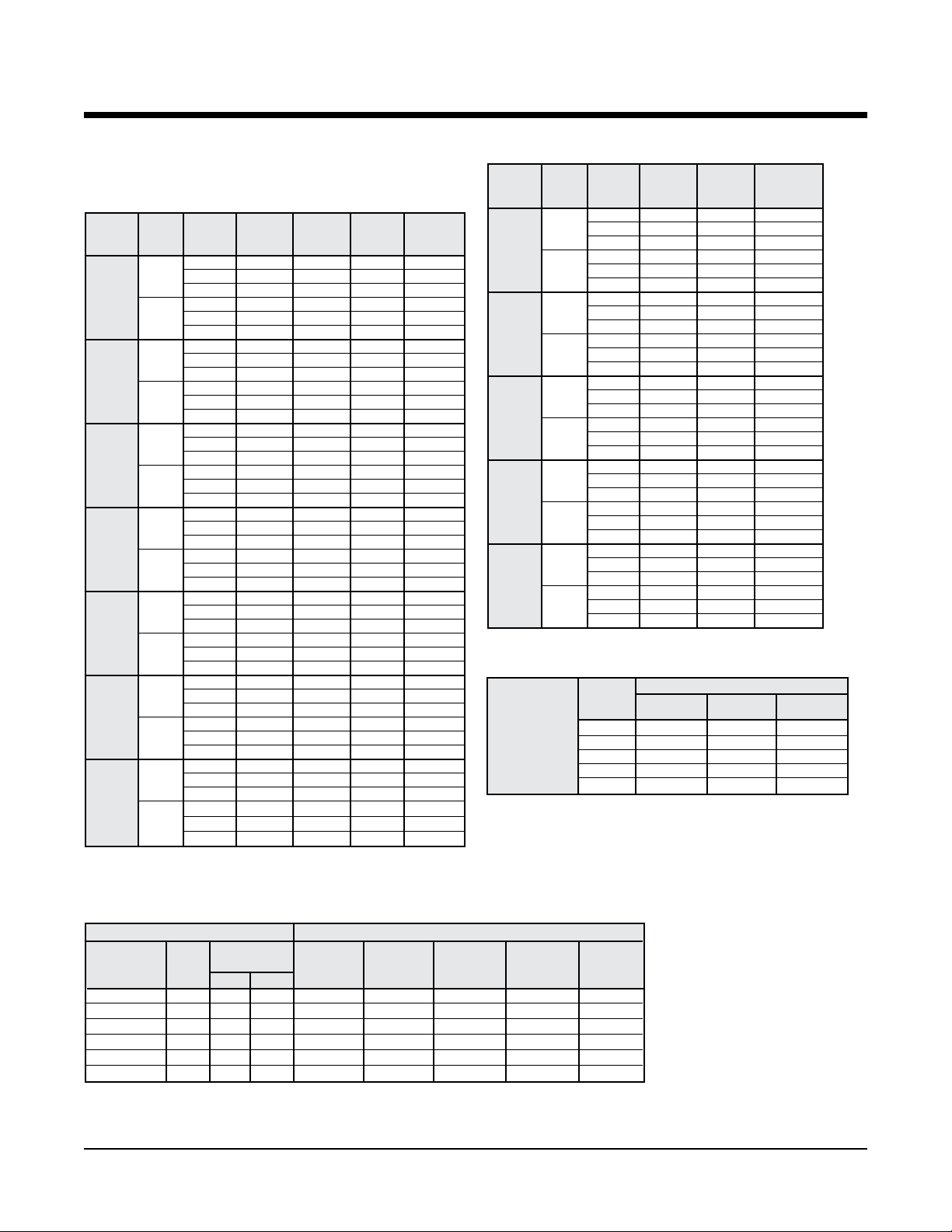
Capacity Data – RWH, RGH 300
Cooling capacities shown are gross capacities. For net capacities,
multiply blower bhp required times 2545 Btu per bph and subtract
from total and sensible in tables.
Table 36. Cooling
Total SH Heat
o
EWT(
F) gpm cfm Capacity Btu/h Watts Rejected
Btu/h Btu/h
44
40
68
44
55
68
44
65
68
44
75
68
44
85
68
44
95
68
44
110
68
9,000 320,688 233,148 12,844 364,520
10,000 322,998 242,488 12,852 366,860
11,000 329,302 257,850 13,020 373,740
9,000 324,572 234,764 12,496 367,220
10,000 329,086 247,038 12,580 372,020
11,000 333,402 259,598 12,664 376,620
9,000 305,406 226,844 14,290 354,180
10,000 309,480 238,646 14,374 358,540
11,000 314,054 250,900 14,472 363,450
9,000 310,140 227,220 13,798 357,230
10,000 314,408 238,978 13,878 361,770
11,000 318,994 251,412 13,966 366,660
9,000 295,812 222,928 15,464 348,590
10,000 300,530 235,640 15,564 353,650
11,000 304,188 246,718 15,644 357,580
9,000 299,838 224,554 14,952 350,870
10,000 304,338 235,306 14,994 355,510
11,000 308,450 248,506 15,118 360,050
9,000 285,940 218,918 16,812 343,320
10,000 291,072 230,236 16,862 348,620
11,000 294,500 241,312 16,940 352,320
9,000 289,898 220,508 16,250 345,360
10,000 294,640 233,108 16,344 350,420
11,000 298,228 244,180 16,414 354,250
9,000 276,410 213,304 18,292 338,840
10,000 280,744 225,972 18,404 343,560
11,000 283,954 237,018 18,480 347,030
9,000 279,624 216,350 17,750 340,200
10,000 284,764 227,570 17,788 345,470
11,000 288,106 238,650 17,858 349,060
9,000 266,122 211,278 20,150 334,890
10,000 270,008 221,844 20,166 338,830
11,000 273,182 232,426 20,230 342,230
9,0002 270,264 211,884 19,420 336,540
10,000 273,958 223,334 19,500 340,510
11,000 277,058 234,424 19,566 343,840
9,000 249,724 205,896 23,050 328,390
10,000 252,494 214,678 23,060 331,200
11,000 255,690 228,532 23,178 334,800
9,000 253,262 207,154 22,366 329,600
10,000 256,524 218,918 22,434 333,090
11,000 259,234 230,418 22,494 336,010
Table 36c. Heating
Heating Heat
o
EWT(
F) gpm cfm Capacity Watts Absorpted
Btu/h Btu/h
44
30
68
44
40
68
44
55
68
44
70
68
44
80
68
9,000 210,786 16,902 153,100
10,000 211,164 16,604 154,490
11,000 211,482 16,364 155,630
9,000 214,496 17,054 156,290
10,000 214,934 16,746 157,780
11,000 215,306 16,498 159,000
9,000 237,674 17,626 177,520
10,000 238,220 17,054 180,010
11,000 238,680 16,992 180,690
9,000 244,494 17,786 183,790
10,000 245,144 17,422 185,680
11,000 245,688 17,134 187,210
9,000 281,022 18,714 217,150
10,000 281,902 18,276 219,530
11,000 282,644 17,932 221,440
9,000 290,596 18,998 225,760
10,000 291,692 18,544 228,400
11,000 292,610 18,184 230,550
9,000 330,078 20,172 261,230
10,000 331,480 19,624 264,500
11,000 332,654 19,194 267,140
9,000 342,974 20,540 272,870
10,000 344,686 19,976 276,510
11,000 346,118 19,532 279,460
9,000 364,552 21,314 291,810
10,000 366,398 20,686 295,800
11,000 367,940 20,194 299,020
9,000 379,460 21,776 305,140
10,000 381,730 21,130 309,610
11,000 383,622 20,622 313,240
Table 36d. Heating Correction Multipliers
Heating
Correction
Multipliers 60 1.014 1.038 0.925
Various 65 1.007 1.019 0.963
Entering Air oF 70 1 1 1
dbt Temperature 75 0.993 0.981 1.077
80 0.986 0.961 ––
Ent. Air
Heating Heat of Total
o
F dbt
Btu/h Absorp. Watts
Multipliers
Table 36b. Cooling Performance Correction Factors
Condenser Water Flow Cooling Performance Correction Factors
Cooling Pressure Total Heat Sensible
Cycle gpm
Design ∆T psi Ft.HD. Btu/h
8o 86 9.3 21.6 1.005 0.987 1.002 1.001 1.02
10o 68 5.9 13.7 1.000 1.000 1.000 1.000 1.00
o
12
14
16
20
58 4.4 10.1 0.987 1.012 0.992 0.996 0.98
o
49 3.2 7.3 0.973 1.025 0.985 0.992 0.95
°
43 2.4 5.7 0.960 1.037 0.977 0.988 0.93
o
35 1.6 3.8 0.958 1.054 0.973 0.980 0.91
Drop
Capacity
Watts
Rejection Capacity EER
Input
Btu/h Btu/h
Notes:
1. Above ratings are based on 80
wbt entering air in cooling, 70oF dbt in
heating. For other entering air conditions
see correction factor charts.
2. Above ratings do not include allowance
for water pump power consumption.
3. Heating ratings below 45
on the use of 20% methanol/water anti-
freeze.
4. Interpolation of ratings is permitted.
5. Above ratings are at 208 volts.
o
F dbt, 67oF
o
EWT based
Page 48 of 62 Rooftop Water Source Heat Pumps Catalog 1110
Page 50

Capacity Data – RWH, RGH 360
Cooling capacities shown are gross capacities. For net capacities,
multiply blower bhp required times 2545 Btu per bph and subtract
from total and sensible in tables.
Table 37. Cooling
Total SH Heat
o
EWT(
F) gpm cfm Capacity Btu/h Watts Rejected
62
40
93
62
55
93
62
65
93
62
75
93
62
85
93
62
95
93
62
110
93
11,000 434,250 300,200 17,716 494,710
12,000 440,126 312,470 17,848 501,040
13,000 445,902 324,898 17,944 507,140
11,000 439,480 303,178 17,150 498,010
12,000 445,592 315,016 17,250 504,470
13,000 451,988 327,096 17,362 511,240
11,000 417,612 294,216 20,164 486,430
12,000 423,120 306,052 20,254 492,250
13,000 427,818 317,658 20,334 497,220
11,000 422,418 296,058 19,468 488,860
12,000 428,032 308,032 19,556 494,780
13,000 432,884 319,672 19,630 499,880
11,000 405,372 288,964 22,078 480,720
12,000 411,214 299,752 22,140 486,780
13,000 414,984 312,424 22,236 490,880
11,000 410,118 290,964 21,316 482,870
12,000 416,116 301,864 21,376 489,070
13,000 420,084 314,454 21,460 493,330
11,000 393,136 282,568 24,238 475,860
12,000 398,130 294,176 24,314 481,110
13,000 401,670 306,806 24,406 484,970
11,000 397,254 285,602 23,430 477,220
12,000 403,044 296,272 23,478 483,170
13,000 407,416 307,784 23,538 487,750
11,000 379,742 276,840 26,718 470,930
12,000 383,716 289,642 26,818 475,250
13,000 387,566 301,274 26,886 479,330
11,000 384,440 278,908 25,822 472,570
12,000 388,600 291,688 25,908 477,020
13,000 392,652 303,262 25,964 481,270
11,000 365,784 270,944 29,524 466,550
12,000 369,360 283,896 29,628 470,480
13,000 374,614 295,824 29,698 475,970
11,000 370,454 272,938 28,560 467,930
12,000 374,238 285,818 28,646 472,010
13,000 378,006 297,372 28,702 475,970
11,000 340,246 262,236 34,226 457,060
12,000 345,786 273,476 34,256 462,700
13,000 348,756 285,944 34,400 466,160
11,000 344,864 264,130 33,152 458,010
12,000 349,334 274,952 33,174 462,560
13,000 354,364 286,424 33,238 467,810
Btu/h Btu/h
Table 37c. Heating
Heating Heat
o
EWT(
F) gpm cfm Capacity Watts Absorpted
62
30
93
62
40
93
62
55
93
62
70
93
62
80
93
11,000 281,798 25,552 194,590
12,000 282,046 25,136 196,260
13,000 282,250 24,796 196,630
11,000 287,010 25,716 199,240
12,000 287,166 25,298 200,820
13,000 287,450 24,942 202,320
11,000 319,776 26,684 228,700
12,000 320,166 25,716 232,400
13,000 321,070 25,804 233,000
11,000 326,890 26,932 234,970
12,000 327,370 26,402 237,260
13,000 327,994 25,990 239,290
11,000 379,220 28,250 282,800
12,000 379,924 27,580 285,790
13,000 380,540 27,028 288,290
11,000 388,588 28,512 291,280
12,000 389,466 27,820 294,520
13,000 390,232 27,250 297,230
11,000 446,686 30,236 343,490
12,000 447,932 29,366 347,710
13,000 449,022 28,658 351,210
11,000 458,962 30,590 354,560
12,000 460,720 29,674 359,440
13,000 462,060 28,942 363,280
11,000 493,874 31,632 385,910
12,000 495,648 30,618 391,150
13,000 497,194 29,798 395,490
11,000 508,212 32,048 398,830
12,000 510,406 30,996 404,620
13,000 512,308 30,146 409,420
Btu/h Btu/h
Table 37d. Heating Correction Multipliers
Heating
Correction
Multipliers 60 1.014 1.038 0.925
Various 65 1.007 1.019 0.963
Entering Air oF 70 1 1 1
dbt Temperature 75 0.993 0.981 1.077
80 0.986 0.961 ––
Ent. Air
Heating Heat of Total
o
F dbt
Btu/h Absorp. Watts
Multipliers
Table 37b. Cooling Performance Correction Factors
Condenser Water Flow Cooling Performance Correction Factors
Cooling Pressure Total Heat Sensible
Cycle gpm
Design ∆T psi Ft.HD. Btu/h
8o 119 20.1 46.4 1.005 0.987 1.002 1.001 1.02
10o 93 12.5 29.0 1.000 1.000 1.000 1.000 1.00
12
14
16
20
o
80 9.4 21.7 0.987 1.012 0.992 0.996 0.98
o
68 6.9 15.9 0.973 1.025 0.985 0.992 0.95
o
60 5.4 12.6 0.960 1.037 0.977 0.988 0.93
o
48 3.6 8.2 0.958 1.054 0.973 0.980 0.91
Drop
Capacity
Watts
Rejection Capacity EER
Input
Btu/h Btu/h
Notes:
1. Above ratings are based on 80
wbt entering air in cooling, 70oF dbt in
heating. For other entering air conditions
see correction factor charts.
2. Above ratings do not include allowance
for water pump power consumption.
3. Heating ratings below 45
on the use of 20% methanol/water anti-
freeze.
4. Interpolation of ratings is permitted.
5. Above ratings are at 208 volts.
o
F dbt, 67oF
o
EWT based
Catalog 1110 Rooftop Water Source Heat Pumps Page 49 of 62
Page 51
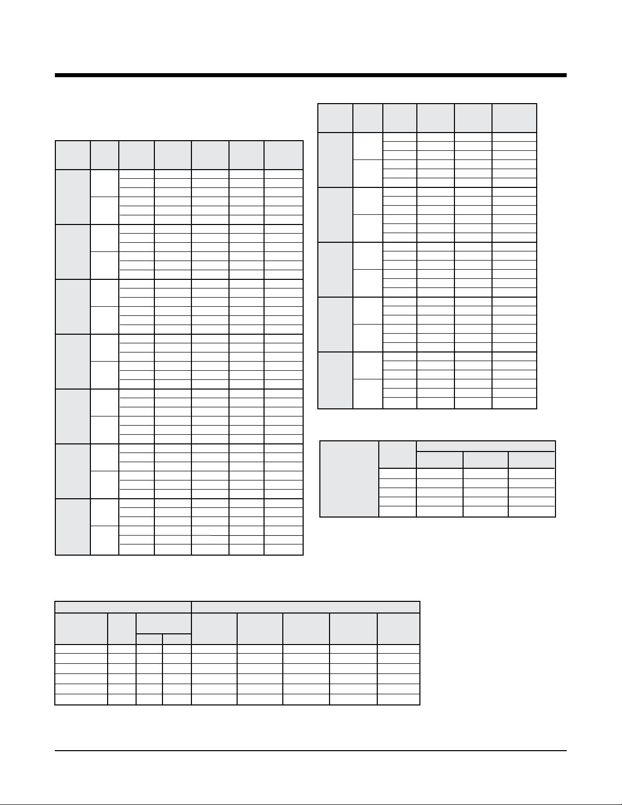
Capacity Data – RWH, RGH 420
Cooling capacities shown are gross capacities. For net capacities,
multiply blower bhp required times 2545 Btu per bph and subtract
from total and sensible in tables.
Table 38. Cooling
Total SH Heat
o
EWT(
F) gpm cfm Capacity Btu/h Watts Rejected
66
40
135
66
55
135
66
65
135
66
75
135
66
85
135
66
95
135
66
110
135
Btu/h Btu/h
13,000 508,400 356,700 22,900 586,400
14,000 515,500 367,100 22,900 593,700
15,000 521,000 379,400 23,000 599,600
13,000 522,000 360,300 21,300 594,700
14,000 529,000 372,800 21,400 601,900
15,000 535,100 385,000 21,500 608,300
13,000 488,500 346,000 25,500 575,400
14,000 494,200 358,200 25,600 581,500
15,000 499,100 370,100 25,700 586,800
13,000 502,000 351,600 23,700 582,900
14,000 508,200 364,200 23,800 589,400
15,000 513,700 376,200 23,900 595,200
13,000 473,600 339,700 27,600 567,700
14,000 478,700 351,800 27,700 573,200
15,000 483,200 363,500 27,800 578,000
13,000 487,200 345,500 25,600 574,700
14,000 493,000 357,800 25,700 580,800
15,000 498,100 369,700 25,800 586,200
13,000 456,400 335,600 30,200 559,300
14,000 460,900 347,700 30,300 564,200
15,000 466,400 361,000 30,400 570,200
13,000 471,500 338,900 27,900 566,700
14,000 476,800 351,000 28,000 576,400
15,000 480,600 364,400 28,100 576,400
13,000 439,000 328,500 33,000 551,700
14,000 444,300 337,800 32,900 556,700
15,000 448,100 353,200 33,200 561,600
13,000 453,900 333,400 30,500 558,100
14,000 458,500 345,500 30,600 572,200
15,000 464,800 357,200 30,700 569,500
13,000 420,100 321,100 36,400 544,300
14,000 424,900 333,700 36,400 549,300
15,000 429,300 342,800 36,300 553,300
13,000 435,000 326,800 33,700 550,000
14,000 440,400 340,200 33,800 570,800
15,000 444,300 351,500 33,800 559,800
13,000 390,100 309,000 42,200 534,200
14,000 392,700 320,000 42,300 537,100
15,000 394,900 330,800 42,400 539,500
13,000 405,500 315,500 39,200 539,400
14,000 408,800 326,700 39,300 530,700
15,000 411,700 337,700 39,400 546,100
Table 38c. Heating
Heating Heat
o
EWT(
F) gpm cfm Capacity Watts Absorpted
Btu/h Btu/h
66
30
135
66
40
135
66
55
135
66
70
135
66
80
135
13,000 334,800 29,600 233,600
14,000 335,600 29,200 236,000
15,000 336,400 28,800 238,000
13,000 354,800 30,300 251,600
14,000 355,600 29,800 254,000
15,000 356,300 29,400 256,100
13,000 381,500 31,000 275,700
14,000 381,900 30,500 277,900
15,000 382,200 30,000 279,800
13,000 405,700 31,800 297,000
14,000 406,100 31,300 299,400
15,000 406,500 30,800 301,500
13,000 453,600 33,400 339,600
14,000 453,800 32,700 342,200
15,000 454,100 32,100 344,400
13,000 484,500 34,400 367,000
14,000 485,300 33,700 370,300
15,000 486,000 33,100 373,200
13,000 525,900 35,900 403,300
14,000 527,400 35,100 407,700
15,000 528,500 34,400 411,200
13,000 559,000 37,100 432,200
14,000 562,100 36,300 432,800
15,000 564,700 35,600 443,400
13,000 569,800 38,300 439,200
14,000 572,700 36,600 447,700
15,000 575,300 35,900 452,900
13,000 599,500 38,700 467,400
14,000 605,500 37,800 465,200
15,000 610,500 37,000 484,200
Table 38d. Heating Correction Multipliers
Heating
Correction
Multipliers 60 1.014 1.038 0.925
Various 65 1.007 1.019 0.963
Entering Air oF 70 1 1 1
dbt Temperature 75 0.993 0.981 1.077
80 0.986 0.961 ––
Ent. Air
Heating Heat of Total
o
F dbt
Btu/h Absorp. Watts
Multipliers
Table 38b. Cooling Performance Correction Factors
Condenser Water Flow Cooling Performance Correction Factors
Cooling Pressure Total Heat Sensible
Cycle gpm
Design ∆T psi Ft.HD. Btu/h
8o 135 17 39.9 1.005 0.987 1.002 1.001 1.02
10o 108 12 26.7 1.000 1.000 1.000 1.000 1.00
12
14
16
20
o
90 8 19.3 0.987 1.012 0.992 0.996 0.98
o
75 6 13.9 0.973 1.025 0.985 0.992 0.95
o
66 5 11.0 0.960 1.037 0.977 0.988 0.93
o
54 3 7.7 0.958 1.054 0.973 0.980 0.91
Drop
Capacity
Watts
Rejection Capacity EER
Input
Btu/h Btu/h
Notes:
1. Above ratings are based on 80
wbt entering air in cooling, 70oF dbt in
heating. For other entering air conditions
see correction factor charts.
2. Above ratings do not include allowance
for water pump power consumption.
3. Heating ratings below 45
on the use of 20% methanol/water anti-
freeze.
4. Interpolation of ratings is permitted.
5. Above ratings are at 208 volts.
o
F dbt, 67oF
o
EWT based
Page 50 of 62 Rooftop Water Source Heat Pumps Catalog 1110
Page 52

Correction Factors – RWH, RGH 036 – 420
Table 39. Cooling Correction Multipliers
Ent. Air
o
F Total
wbt Cooling
61 0.911 0.93 0.983 0.927 0.83 0.91 1.00 1.09 1.18 — — — — — —
63 0.938 0.95 0.989 0.949 0.74 0.83 0.91 1.00 1.09 1.18 — — — — —
65 0.968 0.97 0.994 0.973 0.65 0.74 0.83 0.91 1.00 1.09 1.18 1.27 — — —
67 1.000 1.00 1.000 1.000 0.56 0.65 0.73 0.82 0.91 1.00 1.09 1.18 1.27 — —
69 1.035 1.03 1.007 1.029 — 0.56 0.65 0.73 0.82 0.91 1.00 1.08 1.17 1.26 —
71 1.072 1.06 1.012 1.060 — — 0.56 0.64 0.73 0.82 0.9 0 0.99 1.08 1.17 1.26
73 1.108 1.09 1.019 1.092 — — — — 0.64 0.72 0.81 0.90 0.99 1.07 1.16
Table 40. Supplemental Electric Heaters
ARRANGEMENT UNIT SIZE
036 – 420 3.8 10.4 5.0 12.1 5.0 12.0
048 – 420 11.3 31.2 15.0 36.1 15.0 18.0
096 – 420 15.0 41.6 20.0 48.1 20.0 24.1
Horizontal
096 – 420 22.5 62.5 30.0 72.2 30.0 36.1
120 – 420 26.3 72.9 35.0 84.2 35.0 42.1
120 – 420 30.0 83.3 40.0 96.2 40.0 48.1
180 – 420 37.5 104.1 50.0 120.3 50.0 60.1
180 – 420 45.0 124.9 60.0 144.3 60.0 72.2
Note:Electricheatersonunitsizes036through240canbeeldinstalled.
096 – 420 18.8 52.0 25.0 60.1 25.0 30.1
Multipliers
EER Total Watts Heat Rej.
Cooling Correction Multipliers – At Various Entering Air oF dbt and oF wbt
70 72 74 76 78 80 82 84 86 88 90
HEATER kW FLA HEATER kW FLA HEATER kW FLA
208/60/3 240/60/3 480/60/3
Multipliers for Sensible Cooling
At Entering Air oF dbt
VOLTAGE
Minimum circuit ampacity (MCA) for wire sizing
For units less supplemental electric heat: Use values from tables on pages 37 and 38.
For supplemental electric heat: Optional separate power supply for the electric heater. For the electric heater, MCA = 1.25 x
heater amps.
For unit with supplemental electric heat: Single point power. In this case, the electric heater can operate simultaneously with
the compressor(s).
Minimum circuit ampacity = [(Largest comp. RLA + electric heater amps) x 1.25 + FLA of all other motors and compressors]
Example: RWH150, 208-3-60, 2 hp
7.5 kW electric heater
(20.0 + 20.8) x 1.25 = 51.0 compressor 1 and electric heat
20.0 compressor 2
6.2 fan motor
77.2 Minimum Circuit Ampacity
Maximum fuse size
For units less supplemental electric heat: Use values from tables on pages 37 and 38
For supplemental electric heat: Optional separate power supply for the electric heater. For the electric heater, MFS = 1.25 x
heater amps.
For unit with supplemental electric heat: Single point power. In this case, the electric heater can operate simultaneously with
the compressor(s).
Max. fuse size = (2.25 x compressor RLA) + FLA of all other motors and compressors + electric heater amps
Select the next smaller from the following standard fuse sizes: 15, 20, 25, 30, 35, 40, 45, 50, 60, 70, 80, 90, 100, 110, 125, 150, 175, 200,
225, 250, and 300.
Example: Same unit size from above -
2.25 x 20.0 = 45.0 compressor 1
20.0 compressor 2
20.8 electric heater
6.2 fan motor
92.0 Total Amps Max. fuse size: 90 Amperes
Note: in some instances with relatively large electric heat loads, the value computed for maximum fuse size will be less than the minimum
circuit ampacity. In this situation, the maximum fuse size is the same as minimum circuit ampacity or the next higher fuse size. The maximum fuse size can not be less than the minimum ciricuit ampacity. If so, increase the maximum fuse size.
Catalog 1110 Rooftop Water Source Heat Pumps Page 51 of 62
Page 53
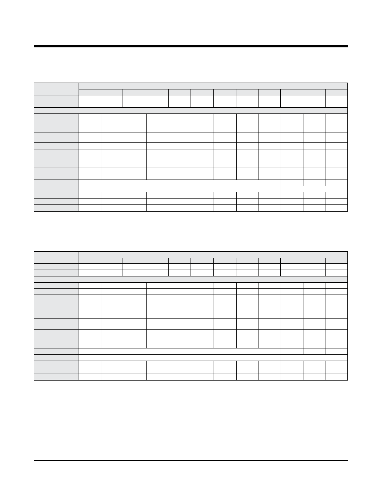
Physical Data – RWH, RGH 036 – 420
Physical Data – English Units
Table 41a.
036 048 060 072 096 120 150 180 240 300 360 420
Fan Qty. 1 1 1 1 2 2 2 2 2 2 2 2
Fan Size (in) 10" x 10" 10" x 10" 10" x 10" 10" x 10" 10" x 10" 10" x 10" 15" x 11" 15" x 11" 15" x 11" 15" x 15" 15" x 15" 15" x 15"
Fan Motor Power (hp)
Small 1/2 3/4 3/4 1 1 1
Medium 3/4 1 1 1
Large 1 1
Coil Face Area
(sq. ft.)
Coil Rows 4 4 4 4 4 4 4 4 4 4 4 4
Condensate Size
3/4" (1) 3/4" (1) 3/4" (1) 3/4" (1) 1" (2) 1" (2) 1" (2) 1" (2) 1" (2) 1" (2) 1" (2) 1" (2)
MPT (Quantity)
Compressor Qty. Recip. (1) Recip. (1) Scroll (1) Scroll (1) Scroll (2) Scroll (2) Scroll (2) Scroll (2) Scroll (2) Scroll (2) Scroll (2) Scroll (3)
Water Conns.,
O.D.S. (in)
Filter Qty. See accessories section 12 12 12
Filter Size (in) See accessories section 18" x 20" x 2"
Oper. Wt. (lbs.) 510 530 550 560 1035 1080 1500 1530 1650 2440 3175 3450
Ship Wt. (lbs.) 520 540 560 570 1055 1100 1540 1570 1690 2490 3225 3500
Curb Wt. (lbs.) 84 84 84 84 122 122 167 167 167 167 330 330
UNIT SIZE
DATA
1
1
1
/2 11/2 2 2 3 3 5 71/2 10 N/A N/A
4.5 4.5 4.5 4.5 8.0 8.0 14.0 14.6 14.6 20.6 26.0 29.2
/2 11/2 2 2 3 5 71/2 10 15
/2 11/2 2 N/A 5 71/2 10
7/8" 1
1
/8" 11/8" 11/8" 15/8" 15/8" 15/8" 15/8" 15/8" 21/8" 21/8" 21/8"
Physical Data – SI Units
Table 41b.
036 048 060 072 096 120 150 180 240 300 360 420
Fan Qty. 1 1 1 1 2 2 2 2 2 2 2 2
Fan Size (mm) 254 x 254 254 x 254 254 x 254 254 x 254 254 x 254 254 x 254 381 x 279 381 x 279 381 x 279 381 x 381 381 x 381 381 x 381
Fan Motor Power (watts)
Small 373 560 560 746 746 1119 1119 1492 N/A 3730 5595 7460
Medium 560 746 746 1119 1119 1492 1492 2238 3730 5595 7460 11186
Large 1 1
Coil Face Area
(sq. m.)
Coil Rows 4 4 4 4 4 4 4 4 4 4 4 4
Condensate Size
MPT (Quantity)
Compressor Qty. Recip. (1) Recip. (1) Scroll (1) Scroll (1) Scroll (2) Scroll (2) Scroll (2) Scroll (2) Scroll (2) Scroll (2) Scroll (2) Scroll (3)
Water Conns., O.D.
(mm)
Filter Qty. See accessories section 12 12 12
Filter Size (mm) See accessories section 457 x 508 x 51
Oper. Wt. (kg) 231 240 250 254 470 490 680 694 748 1107 1440 1565
Ship Wt. (kg) 236 245 254 259 479 499 699 712 767 1130 1463 1587
Curb Wt. (kg) 38 38 38 38 56 56 76 76 76 76 150 150
UNIT SIZE
DATA
1
/
0.42 0.42 0.42 0.42 0.74 0.74 1.30 1.36 1.36 1.91 2.42 2.71
11/
2
2
2 2 3 3 5 7 10 –– ––
19 (1) 19 (1) 19 (1) 19 (1) 25 (2) 25 (2) 25 (2) 25 (2) 25 (2) 25 (2) 25 (2) 25 (2)
653 839 839 839 1212 1212 1212 1212 1212 1585 1585 1585
Page 52 of 62 Rooftop Water Source Heat Pumps Catalog 1110
Page 54

Fan Performance Data – RWH, RGH 036 – 420
English Units
Table 42.
EXTERNAL STATIC PRESSURE (INCHES W.C.)
UNIT SIZE CFM
1,100 996 .4 1,080 .4 1,180 .5 1,240 .6 1,350 .6 1,440 .7 1,540 .8
036 1,200 1,019 .4 1,120 .4 1,220 .5 1,300 .6 1,410 .7 1,480 .8 1,560 .9
1,300 1,042 .5 1,160 .5 1,250 .6 1,330 .7 1,420 .8 1,510 .9 1,580 .9
1,700 1,074 .7 1,164 .8 1,249 1.0 1,328 1.1 1,404 1.2 1,475 1.3 1,542 1.5
048 1,800 1,091 .8 1,177 .9 1,261 1.0 1,340 1.2 1,414 1.3 1,485 1.4 1,552 1.6
1,900 1,108 .9 1,191 1.0 1,272 1.1 1,350 1.3 1,424 1.4 - - - -
1,800 1,174 .8 1,248 .9 1,319 1.0 1,389 1.1 1,457 1.2 1,524 1.3 1,589 1.5
060 2,000 1,195 .9 1,264 1.0 1,332 1.1 1,398 1.2 1,463 1.4 1,526 1.5 - -
2,200 1,238 1.1 1,303 1.2 1,367 1.3 1,429 1.4 - - - - - -
2,000 1,212 .9 1,281 1.1 1,349 1.2 1,414 1.3 1,478 1.4 1,541 1.5 1,603 1.6
072 2,300 1,284 1.2 1,347 1.4 1,409 1.5 1,469 1.6 1,528 1.7 1,585 1.8 1,642 2.0
2,600 1,360 1.6 1,418 1.7 1,475 1.8 1,531 2.0 - - - - - -
2,800 980 .8 1,070 .9 1,150 1.1 1,230 1.3 1,320 1.4 1,410 1.6 1,480 1.8
096 3,200 1,010 1.0 1,090 1.2 1,190 1.3 1,250 1.5 1,350 1.7 1,420 1.8 - -
3,600 1,050 1.3 1,150 1.5 1,220 1.7 1,300 1.8 1,380 1.9 - - - -
3,500 1,104 1.4 1,181 1.5 1,301 1.7 1,328 1.9 1,399 2.2 1,467 2.4 1,535 2.6
120 4,000 1,188 1.8 1,257 2.0 1,325 2.2 1,392 2.4 1,456 2.7 1,519 2.9 - -
4,500 1,271 2.4 1,335 2.6 1,397 2.8 1,458 3.0 - - - - - -
4,500 704 1.2 765 1.4 823 1.6 860 1.8 900 2.2 955 2.4 1,000 2.5
150 5,000 743 1.5 800 1.7 854 2.0 907 2.2 957 2.5 990 2.8 1,020 2.9
5,500 783 1.9 836 2.1 887 2.3 936 2.9 984 2.9 - - - -
5,500 783 1.9 836 2.1 887 2.3 936 2.6 984 2.9 1,030 3.2 1,070 3.5
180 6,000 834 2.3 884 2.6 932 2.8 978 3.1 1,023 3.4 1,067 3.7 1,110 4.0
6,500 884 2.8 930 3.1 975 3.4 1,019 3.7 1,062 4.0 1,104 4.3 1,144 4.6
7,000 898 3.2 943 3.5 987 3.8 1,029 4.1 1,070 4.4 1,111 4.7 1,150 5.0
240 8,000 964 4.3 1,005 4.6 1,045 4.9 1,084 5.3 1,122 5.6 1,159 5.9 1,195 6.3
9,000 1,030 5.7 1,068 6.0 1,105 6.3 1,141 6.7 1,176 7.1 1,211 7.4 - -
9,000 936 4.5 982 4.9 1,026 5.3 1,071 5.7 1,114 6.1 1,157 6.5 1,200 6.9
300 10,000 999 5.8 1,041 6.2 1,081 6.6 1,122 7.1 1,162 7.5 1,201 7.9 1,241 8.3
11,000 1,061 7.3 1,099 7.8 1,137 8.2 1,174 8.7 1,211 9.1 1,248 9.6 - -
11,000 891 5.6 932 6.0 973 6.4 1,012 6.8 1,051 7.2 1,090 7.7 1,127 8.1
360 12,000 945 6.9 984 7.4 1,021 7.8 1,058 8.3 1,095 8.7 1,131 9.2 1,166 9.7
13,000 999 8.5 1,036 9.0 1,071 9.4 1,106 9.9 - - - - - -
13,000 962 8.0 999 8.5 1,036 9.0 1,071 9.4 1,106 9.9 1,140 10.4 1,174 10.9
420 14,000 1,019 9.8 1,054 10.3 1,088 10.8 1,121 11.3 1,154 11.8 1,187 12.3 1,218 12.9
15,000 1,075 11.7 1,108 12.3 1,140 12.8 1,172 13.4 1,203 13.9 1,234 14.5 1,260 15.0
0.4 0.6 0.8 1.0 1.2 1.4 1.6
RPM BHP RPM BHP RPM BHP RMP BHP RPM BHP RPM BHP RPM BHP
Notes: 1. For units with electric heat, add 0.1 inch external static pressure prior to making rpm and Bhp selection.
2. Tables can be interpolated but not extrapolated.
3.Aboveexternalstaticpressurevaluesinclude1"throwawaylters.
“S” Models – Italic
“M” Models – Regular
“L” Models – Bold Italic
Catalog 1110 Rooftop Water Source Heat Pumps Page 53 of 62
Page 55

Dimensional Data – RWH, RGH 036 – 072
Horizontal unit
Duct connections
SUPPLY AIR
12" x 301⁄2" (30.5 cm x 77.5 cm) 111⁄2" x 30" (29.2 cm x 76.2 cm)
RETURN AIR
161⁄4" x 301⁄4" (41.3 cm x 76.8 cm) 16" x 30" (40.6 cm x 76.2 cm)
WITH ELEC HEAT W/O ELEC HEAT
WITH FILTER BOX W/O FILTER BOX
*3 feet (.9 m) of clearance must be left for access to compressor and electrical panel compartment on all three sides.
Roof curb – RWH 036 – 072
Curb Dimensions
Curb A B C D E F G
851-576 48 45 45.25 48.25 22.125 –– 2.125
Page 54 of 62 Rooftop Water Source Heat Pumps Catalog 1110
Page 56

Dimensional Data – RWH, RGH 096 – 120
Horizontal unit
Duct connections
SUPPLY AIR
12" x 461⁄2" (30.5 cm x 118.11 cm)
RETURN AIR
*3 feet (.9 m) of clearance must be left for access to compressor and electrical panel compartment on all three sides.
WITH ELEC HEAT W/O ELEC HEAT
111⁄2" x 46" (29.2 cm x 116.84 cm)
WITH FILTER BOX W/O FILTER BOX
161⁄4" x 461⁄4" (41.3 cm x 117.48 cm)
16" x 46" (40.6 cm x 116.84 cm)
Roof curb – RWH 096 – 120
Curb Dimensions
Curb A B C D E F G
851-577 80 42 42.25 80.25 23 14 2.125
Catalog 1110 Rooftop Water Source Heat Pumps Page 55 of 62
Page 57

Dimensional Data – RWH, RGH 150 – 240
Horizontal unit
Duct connections
SUPPLY AIR
RETURN AIR
*3 feet (.9 m) of clearance must be left for access to compressor and electrical panel compartment on all three sides.
WITH ELEC HEAT W/O ELEC HEAT
12" x 703⁄4" (30.5 cm x 179.71 cm)
WITH FILTER BOX W/O FILTER BOX
161⁄4" x 701⁄2" (41.3 cm x 179.07 cm) 16" x 701⁄4" (40.6 cm x 179.07 cm)
111⁄2" x 701⁄4" (29.2 cm x 178.44 cm)
Roof curb 150 – 240
Curb Dimensions
Curb A B C D E F G
851-564 82 68 68.25 82.25 20 24 2.125
Page 56 of 62 Rooftop Water Source Heat Pumps Catalog 1110
Page 58

Dimensional Data – RWH, RGH 300
Horizontal unit
*3 feet (.9 m) of clearance must be left for access to compressor and electrical panel compartment on all three sides.
Roof curb 300
Curb Dimensions
Curb A B C D E F G
851-575 144 71.5 71.75 144.25 48.5 48.5 2.125
Catalog 1110 Rooftop Water Source Heat Pumps Page 57 of 62
Page 59

Dimensional Data – RWH, RGH 360
Horizontal unit
*3 feet (.9 m) of clearance must be left for access to compressor and electrical panel compartment on all three sides.
Roof curb 360
Curb Dimensions
Curb A B C D E F G
851-575 144 71.5 71.75 144.25 48.5 48.5 2.125
Page 58 of 62 Rooftop Water Source Heat Pumps Catalog 1110
Page 60

Dimensional Data – RWH, RGH 420
Horizontal unit
Roof curb 420
Catalog 1110 Rooftop Water Source Heat Pumps Page 59 of 62
Page 61

Accessories
Filter Box / Filter Dimensions
Table 43.
RWH/RGH
Model
16" x 20" x 2" / (2)
20" x 20" x 2" / (2)
036 - 072 725-20 15" x 30" x 2" / (2)
096 - 120 725-21
180 - 240 725-22
300-420 Filter Rack In Unit 18" x 20" x 2" / (12)
Filter Box No. Filter Size / (Qty.)
15" x 20" x 2" / (4)
20" x 25" x 2" / (4)
Filter Box / Filter Dimensions & Size
Table 44.
Models Used Filter Box Filter
With
No.
036-072 725-20 301/4 201/4 18 2"
096-120 725-21 46
180-240 725-22 70
A B C
1
/4 161/4 23 2"
1
/4 161/4 23 2"
Size
Supplemental Electric Heaters
Filters
The angle lter accessory is fully insulated and is eld
installed to the return air connection of unit sizes 036 thru
240. All RWH, RGH 300 thru 420 are shipped with 2" thick
disposable glass ber media lters factory installed. Aluminum metal media lters are also available.
Table 45. - Electric Heater Dimensions
RWH/RGH 036-060 1-25 32
RWH/RGH 096-120
30.1-60 481/
RWH/RGH 120-300 30.1-60 721/
kW
For Unit
Range
A B C* D E F G H
1
/
2
24 11
3
6 22 13
/
4
3
1-30 481/2 22 12 6 20 14 461/
26 12 6 24 14 46
2
1-30 721/2 22 161/4 6 20 181/4 701/
30.1-60 721/
26
2
26
2
6 24
161/
4
6 24
161/
4
181/
181/
/
4
70
4
70
4
1
30
1
1
1
3
11
/
/
/
/
/
2
2
2
2
2
2
4
12
12
1
16
/
4
161/
4
161/
4
Page 60 of 62 Rooftop Water Source Heat Pumps Catalog 1110
Page 62

Engineering Guide Specications – RWH, RGH
General
Furnish and install McQuay Model RWH/RGH Series A
water source heat pump per plans and specications. Capacity and Energy Efciency shall not be less than scheduled. Unit shall be provided with factory installed options
listed below.
Approvals
Unit shall be design certied to conform to appropriate
UL/ANSI Standards by ETL or other nationally recognized
testing laboratory.
Cabinet
Cabinet shall be constructed of G-90 galvanized steel with
gauge thickness of: Bases - 16 gauge; Corner Posts and
Tops - 18-gauge; Access Panels - 20-gauge. The interior of
the indoor air side is to be thermally insulated with 1 inch
thick - 11/2 pound density glass ber insulation. A closed
cell neoprene liner is to be installed on the underside of
the base pan for noise reduction and weather seal to the
roof curb. The cabinet is to be mounted on two steel rails
to facilitate installation. The design of the cabinet is to al-
low access to the compressor and electrical panel without
impairing unit operation.
Sloped Stainless Steel Condensate
Drain Pan
The condensate drain pan shall be sloped to comply with
ASHRAE Standard 62-1089R and fabricated from stainless
steel. The bottom shall then be insulated with 5/8” closed
cell neoprene insulation. The drain pan shall be furnished
dual MPT drain ttings positioned at the exterior of the
cabinet.
Non Rust Base
Unit base pan shall be coated with a mastic compound to
a uniform 1/4” wet depth and air dried to prevent rain or
condensate from contacting steel on the bottom of the base
pan.
Paint Finish
Constructed of hot dipped galvanized G-90 steel that is
chemically treated with zinc phosphate, coated with 0.2 to
0.3 MIL polyurethane primer then nished with 0.7 to 0.8
MIL polyester top coat, these attractive units are suitable
for a variety of applications. Finish meets or exceeds 1,000
hour Salt Spray Test per ASTM B117-97.
Non-Corroding Hardware
All exterior hardware nuts, bolts, and washers shall be
stainless steel (Type 304). All exterior screws shall be steel
coated with Magnigard Silver 17.
Assembly and Test
The unit shall be completely factory assembled and wired
and thoroughly leak and safety control tested. After assembly, each unit is to be charged and run tested in both the
heating and cooling cycles.
Refrigerant System
The refrigerant system is to include a reciprocating compressor in model 036 and 048 or scroll compressors in
models 060 and larger, with a crankcase heater and thermal
overload protection. The compressor is to rest on external
rubber isolators. Each system is to include a reversing
valve, accumulator, dual gauge connections for high and
low pressure readings, bi-ow thermal expansion valve
with adjustable superheat, coaxial counterow water coil
with inner copper tube and outer steel tube, and copper tube
aluminum plate-nned indoor air coil. Safety controls are to
include low pressure safety control/loss of charge protector
(auto-reset) and high pressure manual reset safety system.
Unit shall include a compressor logic control module with a
circuit to lock compressor off in the event one of the safety
controls shall have been activated. Unit shall include a
circuit to bypass the 30 psig low pressure cutout at start-up
for 90 seconds. Unit may not be restarted until the room
thermostat has been turned off and then on again.
Electrical Controls
Internally wired controls are to include the compressor
control module(s) and the blower and compressor motor
contactors or starters. The 24 volt control circuit includes
a transformer and low voltage terminal board for external
thermostat control hookup.
Fan Section
A forward curved, statically and dynamically balanced,
DWDI centrifugal blower(s) is to be used. Both the
blower(s) and housing(s) are to be galvanized steel. The
blower wheel(s) is to be mounted on a solid steel shaft supported by sealed ball bearings. The shaft is to be driven by
adjustable belt drive sheaves connected to a 1725 rpm motor with sealed ball bearings. The sealed bearings on both
the blower shaft and motor are permanently lubricated.
Filters
2-inch thick disposable glass ber media lters are to be
installed in the factory mounted at lter rack on the return
air opening of model sizes 300, 360 and 420. Field installed
lter boxes for all other model sizes shall be furnished with
2 inch thick disposable glass ber media lters. Filters are
to be located downstream of outside air intake.
Catalog 1110 Rooftop Water Source Heat Pumps Page 61 of 62
Page 63

Page 64

®
Total Heat Pump Capability
Large Vertical Units
6 to 25 Ton
Large Horizontal Units
6 to 10 Ton
Rooftop Units
3 to 35 Ton
Ennity Vertical & Horizontal Units
1⁄2 to 5 Ton
Console Units
1⁄2 to 11⁄2 Ton
Water to Water Source
Heat Pump Units
3 to 35 Ton
Warranty
All McQuay equipment is sold pursuant to its standard terms and conditions of sale, including Limited
Product Warranty. Consult your local McQuay Representative for warranty details. Refer to Form
933-43285Y. To nd your local McQuay Representative, go to www.mcquay.com.
This document contains the most current product information as of this printing. For the most up-to-date
product information, please go to www.mcquay.com.
Products Manufactured in an ISO Certied Facility.
©2008 McQuay International (800) 432-1342 www.mcquay.com Catalog 1110-6 (3-08)
 Loading...