

Page 1
Installation and Maintenance Manual IM-805
Group: Light Commercial
Part Number: IM-805
Date: August 2005
Supersedes: March 2005
RG Single Package Gas-Electric
Heating and Cooling Unit
2 to 5 ton
© 2004 McQuay International
IM-805 Page 1
Page 2

Table of Contents
MODEL NOMENCLATURE . . . . . . . . . . . . . . . . . . . . . . . . . 3
INTRODUCTION . . . . . . . . . . . . . . . . . . . . . . . . . . . . . . . . .4
General Description . . . . . . . . . . . . . . . . . . . . . . . . . . . . . . . 4
Receiving Inspection . . . . . . . . . . . . . . . . . . . . . . . . . . . . . . 4
Codes and Regulations . . . . . . . . . . . . . . . . . . . . . . . . . . . .4
Important Message to the Installer . . . . . . . . . . . . . . . . . . . .4
Important Message to the Owner . . . . . . . . . . . . . . . . . . . . .4
Recognize Safety Symbols, Words, and Labels . . . . . . . . . .4
Replacement Parts . . . . . . . . . . . . . . . . . . . . . . . . . . . . . . . .4
GENERAL WARNINGS . . . . . . . . . . . . . . . . . . . . . . . . . . . .5
UNIT LOCATION . . . . . . . . . . . . . . . . . . . . . . . . . . . . . . . . .5
All Installations: . . . . . . . . . . . . . . . . . . . . . . . . . . . . . . . . . . .6
Ground Level Installations Only: . . . . . . . . . . . . . . . . . . . . . .6
Rooftop Installations Only:. . . . . . . . . . . . . . . . . . . . . . . . . . 6
Roof Curb Installations Only:. . . . . . . . . . . . . . . . . . . . . . . . .6
GENERAL INFORMATION. . . . . . . . . . . . . . . . . . . . . . . . . . 7
RIGGING DETAILS. . . . . . . . . . . . . . . . . . . . . . . . . . . . . . . . 7
GAS PIPING . . . . . . . . . . . . . . . . . . . . . . . . . . . . . . . . . . . . . 7
PROPANE GAS INSTALLATION. . . . . . . . . . . . . . . . . . . . 9
Tanks and Piping . . . . . . . . . . . . . . . . . . . . . . . . . . . . . . . . . 9
ELECTRICAL WIRING . . . . . . . . . . . . . . . . . . . . . . . . . . . .10
Thermostat Location . . . . . . . . . . . . . . . . . . . . . . . . . . . . . 10
Unit Voltage . . . . . . . . . . . . . . . . . . . . . . . . . . . . . . . . . . . .11
Heat Anticipator Setting . . . . . . . . . . . . . . . . . . . . . . . . . . .11
CIRCULATING AIR AND FILTERS . . . . . . . . . . . . . . . . . . 11
Airflow Conversion . . . . . . . . . . . . . . . . . . . . . . . . . . . . . . . 11
Horizontal Air Flow . . . . . . . . . . . . . . . . . . . . . . . . . . . . . . . 11
Down Discharge Applications . . . . . . . . . . . . . . . . . . . . . . . 11
Ductwork . . . . . . . . . . . . . . . . . . . . . . . . . . . . . . . . . . . . . . 11
Filters. . . . . . . . . . . . . . . . . . . . . . . . . . . . . . . . . . . . . . . . . 12
VENTING . . . . . . . . . . . . . . . . . . . . . . . . . . . . . . . . . . . . . .12
Flue Hood Installation . . . . . . . . . . . . . . . . . . . . . . . . . . . . .12
CONDENSATE DRAIN . . . . . . . . . . . . . . . . . . . . . . . . . . . .12
Condensate Drain Connection . . . . . . . . . . . . . . . . . . . . . .12
NORMAL SEQUENCES OF OPERATION . . . . . . . . . . . . 12
Heating. . . . . . . . . . . . . . . . . . . . . . . . . . . . . . . . . . . . . . . . 12
Cooling . . . . . . . . . . . . . . . . . . . . . . . . . . . . . . . . . . . . . . . .12
Fan Only. . . . . . . . . . . . . . . . . . . . . . . . . . . . . . . . . . . . . . . 13
STARTUP, ADJUSTMENTS, AND CHECKS . . . . . . . . . . .13
Heating Startup . . . . . . . . . . . . . . . . . . . . . . . . . . . . . . . . . .13
Cooling Startup. . . . . . . . . . . . . . . . . . . . . . . . . . . . . . . . . . 16
TROUBLESHOOTING. . . . . . . . . . . . . . . . . . . . . . . . . . . . 16
Ignition Control Error Codes . . . . . . . . . . . . . . . . . . . . . . . .16
Abnormal Operation - Heating . . . . . . . . . . . . . . . . . . . . . . .16
Abnormal Operation - Cooling . . . . . . . . . . . . . . . . . . . . . . 17
MAINTENANCE. . . . . . . . . . . . . . . . . . . . . . . . . . . . . . . . . 17
Filter Replacement or Cleaning . . . . . . . . . . . . . . . . . . . . . 17
Cabinet Finish Maintenance. . . . . . . . . . . . . . . . . . . . . . . . 17
Clean Outside Coil (Qualified Servicer Only) . . . . . . . . . . .17
Condenser, Evaporator, and Induced Draft Motors. . . . . . 17
Flame Sensor (Qualified Servicer Only). . . . . . . . . . . . . . . 17
Flue Passages (Qualified Servicer Only) . . . . . . . . . . . . . .18
Cleaning Flue Passages (Qualified Servicer Only) . . . . . . .18
Main Burner Flame (Qualified Servicer Only) . . . . . . . . . . .18
Cleaning Burners . . . . . . . . . . . . . . . . . . . . . . . . . . . . . . . . .18
ACCESSORIES AND FUNCTIONAL PARTS. . . . . . . . . . 19
Sheet Metal Accessories . . . . . . . . . . . . . . . . . . . . . . . . . . 19
Functional Parts . . . . . . . . . . . . . . . . . . . . . . . . . . . . . . . . . 19
General Information . . . . . . . . . . . . . . . . . . . . . . . . . . . . . . 19
APPENDIX . . . . . . . . . . . . . . . . . . . . . . . . . . . . . . . . . . . . .20
This Forced Air Central Unit Design Complies With Requirements Embodied in
The American National Standard / National Standard of Canada Shown Below.
ANSI Z21.47•CSA-2.3 Central Furnaces
"McQuay" is a registered trademark of McQuay International.
© 2004 McQuay International
"Illustrations and information cover the McQuay International products at the time of publication and we reserve the right to make changes in
design and construction at any time without notice."
Manufactured by Goodman Manufacturing Co., L. P., Houston, TX 77008
Page 2 IM-805
Page 3
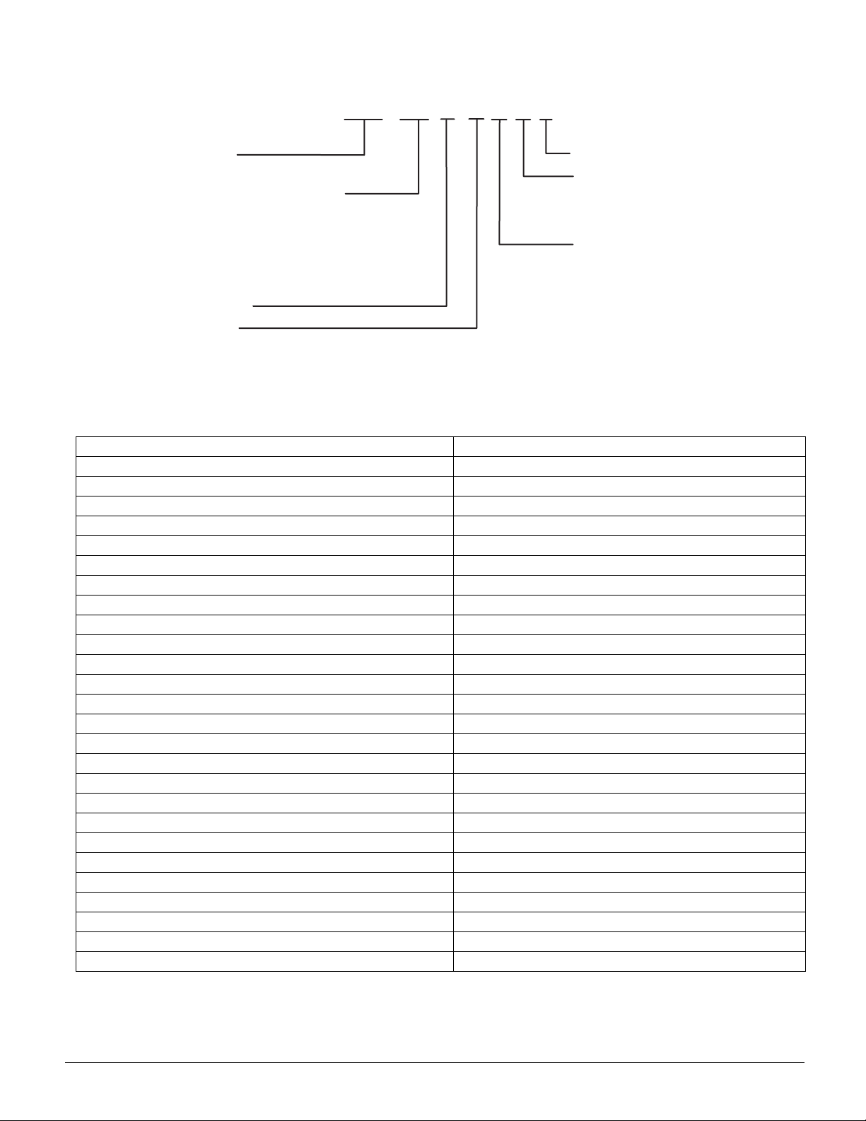
MODEL NOMENCLATURE
M
R
N
2
3
3
4
4
6
*
RG
odel
G = Rooftop Gas
ominal Capacity (tons)
4 = 2
0 = 3
6 = 3
2 = 3-1/2
8 = 4
0 = 5
Vintage
SEER
A = 10
B = 12
* 10 SEER Size 036, 042, 048 and 060 only.
Table 1: Unit Nameplate Model Number Ide nt if i er
024
A
ARY
A
Future Use
Voltage/Phase
P = 208-230/3/60
R = 208-230/1/60
Heating Input
(BTUH)
A = 45,000
B = 70,000
C = 90,000
D = 115,000
E = 140,000
Unit Nameplate McQuay Model Number
GPG10240451A RG024AAARY
GPG10240701A RG024AABRY
GPG10300701A RG030AABRY
GPG10360701A RG036AABRY
GPG10360901A RG036AACRY
GPG10420701A RG042AABRY
GPG10420901A RG042AACRY
GPG10480901A RG048AACRY
GPG10481151A RG048AADRY
GPG10600901A RG060AACRY
GPG10601401A RG060AAERY
GPG10360903A RG036AACPY
GPG10480903A RG042AACPY
GPG10600903A RG048AACPY
GPG10601403A RG060AAEPY
GPG12240451A RG024ABARY
GPG12240701A RG024ABBRY
GPG12300701A RG030ABBRY
GPG12360701A RG036ABBRY
GPG12360901A RG036ABCRY
GPG12420701A RG042ABBRY
GPG12420901A RG042ABCRY
GPG12480901A RG048ABCRY
GPG12481151A RG048ABDRY
GPG12600901A RG060ABCRY
GPG12601151A RG060ABDRY
IM-805 Page 3
Page 4
INTRODUCTION
General Description
These installation instructions cover the outdoor installation of
single package gas-electric heating and cooling units. See the
product catalog applicable to your model for information
regarding specifications applicable to your model and accessories.
Receiving Inspection
McQuay products are carefully inspected prior to shipment
and the carrier has assumed responsibility for loss or damage
upon acceptance of the shipment.
Upon receiving your shipment, check all items carefully
against the Bill of Lading. Inspect the unit and/or accessories
for shipping damage as soon as they are received. Immediately file claims for loss or damage, either shipping or concealed, with the shipping company.
Check the unit nameplate to verify the model number an d electrical characteristics are correct. In the event an incorrect unit
is shipped, it must be returned to the supplier and must NOT
be installed. The manufacturer disclaims all responsibility for
the installation of incorrectly shipped units.
Codes and Regulations
This product is designed and manufactured to permit installation in accordance with National Codes. System design
should, where applicable, follow information presented in
accepted industry guides such as the ASHRAE Handbooks. It
is the installer' s responsibility to inst all the pro duct in ac cordance with National Codes and/or prevailing local codes and
regulations. The manufacturer disclaims all responsibility for
equipment installed in violation of any code or regulations.
Important Message to the Installer
This equipment is to be installed by an experienced installation
company and fully trained personnel. Carefully read all
instructions and take into account any special considerations
prior to installing the unit. Give this manual to the owner and
explain its provisions.
Important Message to the Owner
Read these instructions carefully and keep them near the product for future reference. Although these instructions are
addressed primarily to the installer, useful maintenance information is included. Have the installer acquaint you with the
operation of the product and periodic maintenance requirements.
Recognize Safety Symbols, Words, and Labels
The following symbols and labels are used throughout this
manual to indicate immediate or potential hazards. It is the
owner's and installer's responsibility to read and comply with
all safety information and instructions accompanying these
symbols. Failure to heed safety information increases the risk
of property damage and/or product damage, serious personal
injury or death. Improper installation, operation and maintenance can void the warranty.
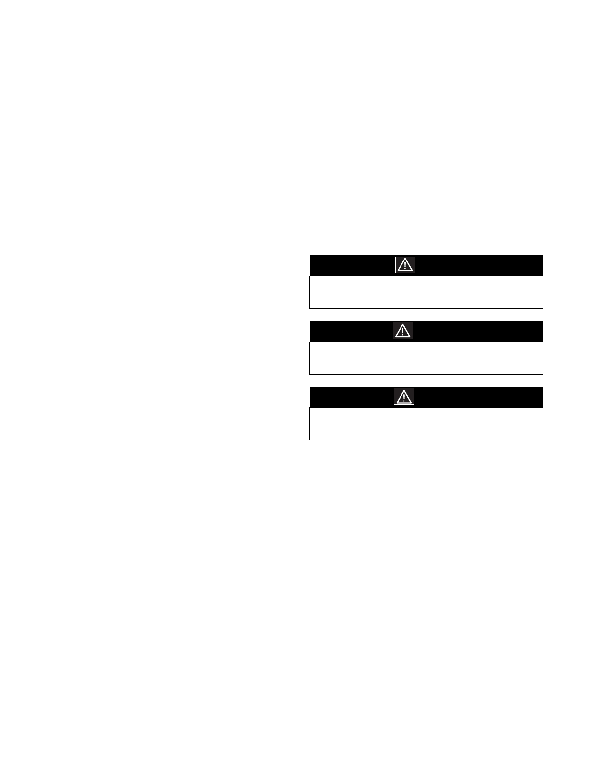
DANGER
Immediate hazards which WILL result in property
damage, product damage, severe personal injury and/
or death.
WARNING
Hazards or unsafe practice CAN result in property
damage, product damage, sever personal injury and/or
death.
CAUTION
Hazards or unsafe practices which CAN result in
property damage, product damage, and/or personal
injury.
Replacement Parts
Replacement parts can be obtained by contacting McQuay at
1
-800-37-PARTS. When contacting McQuay for service or
replacement parts, refer to the model number and serial number of the unit as stamped on the nameplate attached to the
unit.
Page 4 IM-805
Page 5

GENERAL WARNINGS
DANGER
CARBON MONOXIDE (CO) POISONING HAZARD
CO can cause brain damage and death. It is odorless
and colorless. Do not install this unit in any enclosure
or location where fumes many enter an enclosure.
DANGER
To avoid property damage, personal injury or death, do
not store or use gasoline or other flammable vapors or
liquids in the vicinity of this unit or in any area sharing
ventilation.
WARNING
IF YOU SMELL GAS
• Immediately evacuate the area.
• Do not try to light any appliances.
• Do not touch any electrical switches.
• Do not use any phones in your building.
• Immediately call your gas supplier from a phone
located in a neighboring building.
• Follow the gas supplier's instructions.
• If you cannot reach your gas supplier, call the fire
department.
Failure to follow these instructions can result in fire,
explosion, severe personal injury or death.
WARNING
If overheating occurs or the gas supply fails to shut off,
turn off the manual gas shutoff valve outside the
furnace before turning off the electricity supply to avoid
property damage, severe personal injury or death.
WARNING
To avoid property damage, personal injury or death, do
not use this unit if any part has been under water.
Immediately call a qualified service technician to
inspect the furnace an replace any affected part.
WARNING
This product contains or produces substances which
may cause serious illness or death, and which are
known to the State of California to cause cancer, birth
defects or other reproductive harm.
WARNING
To avoid property damage, personal injury or death,
follow the planned maintenance instructions provided in
the "Maintenance" section of this document..
CAUTION
Freezing can burst pipes. Routinely inspect and
monitor unit and premise. If vacant, drain all water
pipes and close water source. Drain hydronic coils and
use alternative heat source.
CAUTION
Do not use this unit as a "construction heater" during
finishing phases of construction on a new structure.
Extremely low return air temperatures and corrosive or
dirty atmosphere can damage unit.
CAUTION
Sheet metal parts, screws, clips and similar items have
sharp edges. Use caution and wear protective clothing
when installing or servicing this equipment.
CAUTION
Keep these instructions in a safe and accessible space
for future reference or in case of an emergency.
UNIT LOCATION
WARNING
To prevent possible equipment damage, property
damage, personal injury or death, all illustrations
included in this manual must be observed when
installing the unit.
IMPORTANT NOTE: Remove wood shipping rails prior to
installation of the unit.
All Installations:
• For proper flame pattern within the heat exchanger and
proper condensate drainage, the unit must be mounted
level.
• The flue outlet hood must be at least 12 inches from any
opening through which flue gases could enter a buil ding,
and at least three feet above any forced air inlet located
within ten feet. The economizer/manual fresh air intake/
motorized fresh air intake and combustion air inlet
mounted on the unit are not affected by this restricti on.
• To avoid possible corrosion of the heat exchanger, do not
locate the unit in an area where the outdoor air (i.e. combustion air for the unit) will be frequently contaminated by
compounds containing chlorine or fluorine. Common
sources of such compounds include swimming pool chemicals and chlorine bleaches, paint stripper, adhesives, paints,
varnishes, sealers, waxes (which are not yet dried) and solvents used during construction and remodeling. Various
commercial and industrial processes may also be sources of
chlorine/fluorine compounds.
IM-805 Page 5
Page 6

• To avoid possible illness or death, do NOT locate outside
air intake device (economizer, manual fresh air intake,
motorized fresh air intake) too close to an exhaust outlet,
gas vent termination or plumbing vent outlet. For specific
distances required, consult local codes.
• Allow minimum clearances from the enclosure for fire protection, proper operation, and service access (see Appendix
Figure 25). These clearances must be permanently maintained.
• The combustion air inlet and flue outlet hoods on the unit
must never be obstructed. If used, do not allow the economizer/manual fresh air damper/ motorized fresh air damper
to become blocked by snow or debris. In some climates or
locations, it may be necessary to elevate the unit to avoid
these problems.
• When the unit is heating, the temperature of the return air
entering the unit must be between 50° F and 100° F.
Ground Level Installations Only:
• When the unit is installed on the ground adjacent to the
building , use a level concrete (or equal) base. Prepare a
base that is 3” larger than the package unit footprint and a
minimum of 3” thick.
• Locate the base where no runoff of water from higher
ground can collect in the unit.
Figure 1. Outside Slab Installation
Figure 2. Rooftop Installation
Roof Curb Installations Only:
• Sufficient structural support must be determined prior to
locating and mounting the curb and package unit.
• Ductwork must be constructed using industry guidelines.
The duct work must be placed into the roof curb before
mounting the package unit.
• Curb insulation, cant strips, flashing and general roofing
material are furnished by the contractor.
Figure 3. Roof Curb Installation
Rooftop Installations Only:
• To avoid possible property damage or personal injury, the
roof must have sufficient structural strength to carry the
weight of the unit(s) and snow or water loads as required
by local codes. Consult a structural engineer to determine
the weight capabilities of the roof.
• The unit may be installed directly on wood floors or on
Class A, Class B, or Class C roof covering material.
• To avoid possible personal injury, provide a flat surface for
service personnel.
Page 6 IM-805
Page 7

GENERAL INFORMATION
WARNING
To prevent property damage, personal injury or death,
due to fire, explosions, smoke, soot, condensation,
electric shock or carbon monoxide, this unit must be
properly installed, repaired, operated, and maintained.
This unit is approved for outdoor installation ONLY. For
proper operation the unit must be installed, operated, and
maintained in accordance with these installation and operating
instructions, all local building codes and ordinances, or in their
absence, with the latest edition of the National Fuel Gas Code
NFPA54/ANSI Z223.1 and National Standard of Canada
CAN/CSA B149 Installation Codes.
The heating and cooling capacities of the unit should be
greater than or equal to the design heating and cooling loads of
the area to be conditioned. The loads should be calculated by
an approved method or in accordance with ASHRAE Guide or
Manual J - Load Calculations published by the Air Conditioning Contractors of America.
Obtain from:
American National Standards Institute
1430 Broadway
New York, NY 10018
RIGGING DETAILS
WARNING
To avoid equipment and property damage, the unit
should remain in an upright position during all rigging
and moving operations.
To facilitate lifting and moving when a crane is used, place the
unit in an adequate cable sling..
IMPORTANT NOTE: If using bottom discharge with roof
curb, ductwork should be attached to the curb prior to installing the unit. Ductwork dimensions are shown in roof curb
installation instructions.
Refer to the Roof Curb Installation Instructions for proper curb
installation. Curbing must be installed in compliance with the
National Roofing Contractors Association Manual.
Lower the unit carefully onto the roof mounting curb. While
rigging the unit, the center of gravity will cause the condenser
end to be lower than the supply air end.
Figure 4. Rigging
GAS PIPING
IMPORTANT NOTE: This unit is factory set to operate on
natural gas at the altitudes shown on the nameplate.
WARNING
To avoid property damage, personal injury or death
when either using propane gas alone or at higher
altitudes, obtain and install the proper conversion kit(s).
Failure to do so can result in unsatisfactory operation
and/or equipment damage. High altitude kits are for
U.S. installations only and are not approved for use in
Canada.
The nameplate is stamped with the model number, type of gas
and gas input rating. Verify that the unit is eq uipped t o oper at e
on the type of gas available. Conversion to LP gas is permitted
with the use of factory-authorized conversion kit LPT-00A.
Table 2: Inlet Gas Pressure
Natural Min. 5.0" W.C., Max. 10.0" W.C.
Propane Min. 11.0" W.C., Max. 13.0" W.C.
Inlet gas pressure must not exceed the maximum value shown
in table above.
For dependable ignition, the minimum supply pressure should
not vary from the value shown in Table 2. In addition, gas
input to the burners must not exceed the rated input shown on
the nameplate. Overfiring of the unit could result in premature
heat exchanger failure.
High Altitude Derate (U.S. Installations Only)
IMPORTANT NOTE: The gas/electric units naturally derate
with altitude. Do not attempt to increase the firing rate by
changing orifices or increasing the manifold pressure. This can
cause poor combustion and equipment failure. At all altitudes,
the manifold pressure must be within 0.3 inches W.C. of the
value listed on the nameplate for the fuel used. At all altitudes
and with either fuel, the air temperature rise must be within the
range listed on the nameplate.
Refer to the Installation Manual provided with the LP kit for
conversion from natural gas to propane gas, and for altitude
adjustments.
Piping
IMPORTANT NOTE: To avoid unsatisfactory operation or
equipment damage due to under-firing of equipment, do not
undersize the natural/propane gas piping from the meter/tank
to the unit. When sizing a trunk line, as shown in Table 3,
include all appliances on that line that co uld be oper ated simu ltaneously.
The nameplate is stamped with the model number, type of gas
and gas input rating. Verify that the unit is equipped to operate
on the type of gas available. The gas line installation must
comply with local codes, or in the absence of local codes, with
the latest edition of the National Fuel Gas Code NFPA 54/
ANSI Z223.1.
IM-805 Page 7
Page 8

Natural Gas Connection
Table 3: Natural Gas Capacity of Pipe in Cubic Feet of Gas
Per Hour (CFH
Length of
Pipe in Feet
10 132 278 520 1050 1600
20 92 190 350 730 1100
30 73 152 285 590 980
40 63 130 245 500 760
50 56 115 215 440 670
60 50 105 195 400 610
70 46 96 180 370 560
80 43 90 170 350 530
90 40 84 160 320 490
100 38 79 150 305 460
Pressure =.50 PSIG or less and Pressure Drop of 0.3" W.C. (Based on 0.60
Specific Gravity Gas)
)
Nominal Black Pipe Size (inches)
1/23/4 11 1/41 1/2
BTUH Furnace Input
CFH =
Heating Value of Gas (BTU/Cubic Foot)
Refer to the Proper Piping Practice drawing for the general
layout at the unit. The following rules apply:
Figure 5. Proper Piping Practice
GROUND JOINT UNION
(INSTALLED AHEAD OF GAS VALVE)
GROMMET
NOTE:
The unit gas supply entrance is factory sealed with
plugs. Keep plugs in place until gas supply is ready
to be installed. Once ready, replace the plugs with the
supplied grommets and install gas supply line.
Gas Piping Checks
DRIP LEG
MANUAL
SHUT-OFF
VALV E
1. Use black iron pipe and fittings for the supply piping. The
use of a flex connector and/or copper piping is permitted as
long as it is in agreement with local codes.
2. Use pipe joint compound on male threads only. Pipe joint
compound must be resistant to the action of the fuel used.
3. Use ground joint unions.
4. Install a drip leg to trap dirt and moisture before it can enter
the gas valve. The drip leg must be a minimum of three
inches long.
5. Use two pipe wrenches when making connection to the gas
valve to keep it from turning.
6. Install a manual shut-off valve in a convenient location
between the meter and the unit (within six feet of unit).
7. Tighten all joints securely.
8. The unit must be connected to the building piping by one of
the following methods:
• Rigid metallic pipe and fittings
• Semirigid
metallic tubing and metallic fittings (Aluminum
alloy tubing must not be used in exterior locations)
• Listed gas appliance connectors, used in accordance with
the terms of their listing, that are completely in the same
room as the equipment
• In the prior two methods above, the connector or tubing
must be protected from physical and thermal damage.
Aluminum alloy tubing and connectors must be coated to
protect against external corrosion when contacting
masonry, plaster or insulation, or when they are subject to
repeated wettings by liquids.
CAUTION
To avoid property damage or personal injury due to fire,
the following instructions must be followed regarding
gas connections and pressure testing:
• The unit and its gas connections must be leak tested
before operation. Because of the danger of explosion
or fire, never use a match or open flame to test for
leaks. Never exceed specified pressures for testing.
Higher pressure may damage the gas v al ve and cause
overfiring, which may result in premature heat
exchange failure.
• This unit and its shut-off valve must be disconnected
from the gas supply during any pressure testing of that
system at test pressures in excess of 1/2 PSIG (3.48
kPa).
• This unit must be isolated from the gas supply system
by closing its manual shut-off valve during any
pressure testing of the gas supply piping system at
test pressures equal to or less than 1/2 PSIG (3.48
kPa).
WARNING
To a v oid property damage or personal injury during air
bleeding, be sure there is no open flame, sparks, arcing
switches on equipment, cigarette or other sources of
ignition in the vicinity or in areas sharing ventilation.
There will be air in the gas supply line after testing for leaks on
a new installation. Before bleeding the line, verify that there is
no flame, arcing switch on equipment, cigarette, or other
source of ignition in the area or areas sharing ventilation.
Bleed air from the line by loosening the ground joint union
until pure gas is expelled. Tighten the union and wait for at
least five minutes until all gas has been evacuated from the
area. The unit is placed in operation by closing the main electrical disconnect switch for the unit.
Page 8 IM-805
Page 9

PROPANE GAS INSTALLATION
WARNING
To avoid property damage, personal injury or death due
to fire or explosion caused by a propane gas leak, install
a gas detecting warning device. Since rust can reduce
the level of odorant in propane gas, a gas detecting
warning device is the only reliable way to detect a
propane gas leak. Contact a local propane gas supplier
about installing a gas detecting warning device.
IMPORTANT NOTE: Propane gas conversion kits must be
installed to convert units to propane gas. See the product catalog for the appropriate kit part number.
All propane gas equipment must conform to the standards of
the National Board of Fire Underwriters (See NBFU Manual
58).
For satisfactory operation, propane gas supply pressure must
be within 9.7 - 10.3 inches W.C. at the manifold with all gas
appliances in operation. Maintaining proper gas pressure
depends on three main factors:
1. Vaporization rate, which depends on (a) temperature of the
liquid, and (b) wetted surface area of the container or containers.
2. Proper pressure regulation.
3. Pressure drop in lines between regulators, and between second stage regulator and the appliance. Pipe size required
will depend on length of pipe run and total load of all appliances.
Tanks and Piping
Complete information regarding tank sizing for vaporization,
recommended regulator settings and pipe sizing is available
from most regulator manufacturers and propane gas suppl iers.
See Figure 6 for typical propane gas piping.
Since propane gas will quickly dissolve white lead or most
standard commercial compounds special pipe dope must be
used. Shellac-based compounds that are resistant to the actions
of liquefied petroleum gases, such as Gasolac®, Stalactic®,
Clyde’ s® o r Joh n Cr ane ®, ar e sa tisf ac tory.
Figure 6. Typical Propane Gas Piping
Table 4: Propane Gas Pipe Sizing
Sizing Between First and Second Stage Regulator
Maximum Propane Capacities listed are based on 1 PSIG Pressure Drop at 10
PSIG Setting. Capacities in 1,000 BTU/HR
Pipe or
Tubing
Lenght,
Feet
30 309 700 1303 2205 3394 1843 3854
40 265 599 1115 1887 2904 1577 3298
50 235 531 988 1672 2574 1398 2923
60 213 481 896 1515 2332 1267 2649
70 196 446 824 1394 2146 1165 2437
80 182 412 767 1297 1996 1084 2267
90 171 386 719 1217 1873 1017 2127
100 161 365 679 1149 1769 961 2009
150 130 293 546 923 1421 772 1613
200 111 251 467 790 1216 660 1381
250 90 222 414 700 1078 585 1224
300 89 201 378 634 976 530 1109
350 82 185 345 584 898 488 1020
400 78 172 321 543 836 454 949
To convert to Capacities at 15 PSIG Settings -- Multiply by 1.130
To convert to Capacities at 5 PSIG Settings -- Multiply by 0.879
Sizing Between Single or Second Stage Regulator and Appliance*
Maximum Propane Capacities Listed are Based on 1/2" W.C. Pressure Drop at
11" W.C. Setting. Capacities in 1,000 BTU/HR
Pipe or
Tubing
Lenght,
*DATA IN ACCORDANCE WITH NFPA PAMPHLET NO. 54
3/8" 1/2" 5/8" 3/4" 7/8" 1/2" 3/4" 1" 1 1/4" 1 1/2"
Feet
10 49 110 206 348 539 291 608 1146 2353 3525
20 34 76 141 239 368 200 418 788 1617 2423
30 27 61 114 192 296 161 336 632 1299 1946
40 23 52 97 164 253 137 284 541 1111 1665
50 20 46 86 146 224 122 255 480 985 1476
60 19 42 78 132 203 110 231 436 892 1337
80 16 36 67 113 174 94 198 372 764 1144
100 14 32 59 100 154 84 175 330 677 1014
125 12 28 52 89 137 74 155 292 600 899
150 11 26 48 80 124 67 141 265 544 815
200 10 22 41 69 106 58 120 227 465 697
250 9 19 36 61 94 51 107 201 412 618
300 8 18 33 55 85 46 97 182 374 560
350 7 16 30 51 78 43 89 167 344 515
400 7 15 28 47 73 40 83 156 320 479
Tubing Size, O.D. Type L
3/8" 1/2" 5/8" 3/4" 7/8" 1/2" 3/4"
Tubing Size, O.D. Type L Nominal Pipe Size, Schedule 40
Nominal Pipe
Size, Schedule
40
First Stage
Regulator
5 to 15 PSIG
(20 PSIG Max.)
200 PSIG
Maximum
Second Stage
Regulator
Continuous
11” W.C.
WARNING
To prevent property damage or serious personal injury
due to fire or explosion caused by a propane gas leak,
install a gas detecting warning device.
• Propane gas is heavier than air and any leaking gas
can settle in any low areas or confined spaces.
• Propane gas odorant may fade, making the gas
undetectable, except with a warning device.
IM-805 Page 9
Page 10

ELECTRICAL WIRING
Thermostat Location
Mount the thermostat approximately five feet above the floor,
in an area that has an inside, vibration-free wall and good air
circulation.
Air movement must not be obstructed by furniture, door, draperies, etc. The thermostat must not be mounted where it will be
affected by drafts, hot or cold water pipes or air ducts in walls,
radiant heat from a fireplace, lamps, the sun, a television, etc.
Consult the Instruction Sheet packaged with thermostat for
mounting instructions.
WARNING
To a void property damage or personal injury due to fire,
use only copper conductors.
CAUTION
To prevent improper operation due to wiring errors,
label all wires prior to disconnection when servicing
controls. Verify proper operation after servicing.
All units have one stage of heating and one stage of mechanical cooling. Units with economizers may use thermostats with
one or two stages of cooling.
WARNING
To avoid injury, electrical shock or death, disconnect
electrical power before servicing or changing any
electrical wiring.
The units are designed for operation on 60 hertz current and at
voltages shown on the nameplate. All internal wiring in the
unit is complete. It is necessary to bring in the power supply to
the contactor as shown on the unit wiring diagram supplied
with the unit. 24-volt wiring must be connected between the
unit control panel and the room thermostat. Do not run control
wiring next to or in the same conduit as higher voltage wiring.
Figure 7. Low Voltage Wiring
0
0
A
4
8
3
-
-
1
0
6
8
1
8
B
0
9
9
-
1
WYR
C
LOW VOLTAGE
CONNECTOR
G
8
K4
K3
L
0
E
0
D
4
-
O
8
M
6
0
1
M
E
T
S
Y
S
N
O
I
T
I
N
.
X
G
I
A
C
M
I
T
A
A
m
M
0
0
O
4
T
z
U
H
A
0
0
6
/
2
.
0
1
5
2
Z
C
I
A
S
V
N
4
2
A
E
G
A
R
T
S
O
S
O
S
W
E
T
R
P
R
M
O
F
O
C
K
A
E
R
B
T2
R
Y
W
G
L
O
O
C
T
2
A
L
E
H
2
L
D
E
2
S
L
U
N
U
2
L
1
L
1
L
I
D
K2
S
F
K1
9
6
2
1
3
2
3
9
6
2
1
6
9
1
3
1
1
C22
1
1
1
1
0
0
1
0
1
1
F1
FUSE 3 AMP MAX
2
2
8
5
2
5
8
7
4
1
1
7
4
1
1
7
4
P
N
O
C
E
120
135
P3
150
P
U
-
D
E
E
P
P2
S
T1
For unit protection, use a fuse or HACR circuit breaker that is
in excess of the circuit ampacity, but less than or equal to the
maximum overcurrent protection device. DO NOT EXCEED
THE MAXIMUM OVERCURRENT DEVICE SIZE
SHOWN ON UNIT NAMEPLATE.
All line voltage connections must be made through weatherproof fittings. All exterior power supply and ground wiring
must be in approved weatherproof conduit. Low voltage wiring from the unit control panel to the thermo stat r equires coded
cable. See below for ground level and rooftop wiring .
Figure 8. Typical Electrical Wiring
Note:Junction box location
shown is optional and is
for illustration purposes only.
JUNCTION BOX
Electrical Power Directly To Junction Box
Refer to the unit wiring diagram for electrical connections.
When installed, the unit must be electrically grounded in
accordance with local codes, or in the absence of local codes,
with the National Electrical Code, ANSI/NFPA No. 70, and/or
the CSA C22.1 Electrical Code. Verify that low voltage con-
nections are waterproof.
WARNING
To avoid the risk of electrical shock, wiring to the unit
must be polarized and grounded.
Electrical Power Routed Through Bottom of Unit
Page 10 IM-805
Page 11

Unit Voltage
The unit transformer is factory connected for 230V operation.
If the unit is to operate on 208V, reconnect the transformer primary lead and induced draft blower motor leads as shown on
the unit wiring diagram.
Heat Anticipator Setting
The heat anticipator is to be set by measuring the load (amperage) at the “R” circuit. Follow the instructions provided by the
thermostat for more details.
Figure 9. Typical Thermostat and Unit 24V Wiring Hookup
G
Y
R
W
R
From
Unit
W
Y
G
CIRCULATING AIR AND FILTERS
Airflow Conversion
Units can easily be converted from horizontal to down-discharge airflow delivery. In down-discharge or high static
installations, the installer should measure the total external
static and review the blower performance charts before performing the installation. In some installations it will be necessary to change the blower speed to prov id e prop er ai r flow.
Horizontal Air Flow
Remove the supply and return duct covers which are attached
to the unit as shown in Figure 10.
Down Discharge Applications
Cut the insulation around bottom openings and remove panels
from the bottom of the unit, saving the screws holding the panels in place.
Ductwork
Duct systems and register sizes must be properly designed for
the CFM and external static pressure rating of the unit. Ductwork should be designed in accordance with the recommended
methods of Air Conditioning Contractors of America Manual
D (Residential) or Manual Q (Commercial). All ductwork
exposed to outdoor conditions must include a weatherproof
barrier and adequate insulation.
A duct system should be installed in accordance with Standards of the National Board of Fire Underwriters for the Installation of Air Conditioning, Warm Air Heating and Ventilating
Systems. Pamphlets No. 90A and 90B.
The supply duct from the unit through a wall may be installed
without clearance. However, minimum unit clearances as
shown in the Appendix must be maintained. Provide the supply duct with an access panel large enough to inspect the air
chamber downstream of the heat exchanger. Tightly attach a
cover to prevent air leaks.
For duct flange dimensions on the unit refer to the Uni t
Dimension illustration in the Appendix.
For down-discharge applications, attach the ductwork to the
roof curb prior to installing the unit. Ductwork dimensions are
shown in the roof curb installation manual.
If desired, supply and return duct connections to the unit may
be made with flexible connections to reduce unit operating
sound transmission.
Figure 10. Duct Cover Installation
Remove these covers
for horizontal duct
applications
Remove these panels
for downflow duct
applications
IM-805 Page 11
Page 12

Filters
CAUTION
To prevent property damage due to fire and loss of
equipment efficiency or equipment damage due to dust
and lint build up on internal parts, never operate unit
without an air filter installed in the return air system.
Even though a return air filter is not supplied with this unit,
there must be a means of filtering all return air. The 12 SEER
size 048 and 060 models are provided with internal filter racks
for down-discharge applications. All units may be externally
filtered.
CONDENSATE DRAIN
Condensate Drain Connection
A 3/4” NPT drain connection is supplied for condensate piping. An external trap must be installed for proper conden sate
drainage.
Figure 12. Drain Connection
DRAIN
CONNECTION
UNIT 2" MINIMUM
Refer to the unit filter size chart in the Appendix for filter size
information.
Filters installed external to the unit should be sized in accordance with their manufacturer’s recommendations. A throwaway filter must be sized for a maximum face velocity of 300
feet per minute.
Filter Installation
Important: When installing a filter, the air flow arrows on the
filter must point toward the circulator blower.
VENTING
NOTE: Venting is self-contained. Do not modif y or blo ck.
Flue Hood Installation
Install the flue hood and bug screen prior to operation of the
unit.
T o inst all th e flue hood cover and bug screen:
1. Remove the flue hood and bug screen from inside the heat
exchanger compartment.
2. Slide the bug screen over the flanges of the flue hood and
attach the flue hood and screen to the unit with the sheet
metal screws provided.
Figure 11. Flue Hood and Bug Screen Installation
FLEXIBLE
TUBING-HOSE
OR PIPE
A POSITIVE LIQUID
SEAL IS REQUIRED
3" MINIMUM
NORMAL SEQUENCES OF
OPERATION
Heating
This unit is equipped with an ignition control that automati-
cally lights the main burner. DO NOT attempt to light the
main burners by any other method.
1. Thermostat calls for heat. The induced draft blower energizes for a 15-second pre-purge.
2. The spark igniter and gas valve energizes for 7 seconds.
NOTE: The igniter produces a very intense electrical spark
that ignites the gas.
3. The 30-second HEAT FAN ON delay time begins.
4. The unit delivers heat to the conditioned space until the
thermostat is satisfied.
5. The gas valve deenergizes. The induced draft blower continues operation for a 29-second post-purge.
6. Ignition control begins timing the HEAT FAN OFF delay.
There is an adjustable HEAT FAN OFF delay of approximately 120/135/150 seconds (factory set at 150). After the
HEAT FAN OFF delay time has elapsed, the blower will
deenergize. This allows any additional heat in the heat
exchanger to be transferred to the conditioned space.
Cooling
1. Thermostat calls for cooling. The compressor and outdoor
FLUE HOOD
BUG SCREEN
fan are energized.
2. Approximately seven seconds later , the indo or fan st ar ts.
3. The unit will deliver cooling to the conditioned space until
the thermostat is satisfied.
4. The compressor and outdoor fan will be deenergized when
the thermostat opens.
5. The indoor fan continues to run for approximately 60 seconds after the thermostat is satisfied. This allows additional cooling from the indoor coil to be transferred to the
conditioned space. Then, the indoor fan stops.
Page 12 IM-805
Page 13

NOTE: A 180-second anti-short cycle is integral to the contr ol
and prevents recycling of the compressor.
Fan Only
1. Thermostat calls for FA N ONLY by ener gizing “G”.
2. Approximately seven seconds later, the indoor fan starts.
Secondary Limit Control
The secondary limit control is located on the top of the blower
scroll assembly. This control opens when elevated temperatures are sensed. Elevated temperatures at the control ar e normally caused by blower failure. The reason for the control
opening should be determined and repaired prior to resetting.
3. The indoor fan continues to run for approximately 60 seconds after “G” is deenergized.
STARTUP, ADJUSTMENTS, AND
CHECKS
Heating Startup
This unit is equipped with an electronic ignition dev ice to
automatically light the main burners. It also has a power vent
blower to exhaust combustion products.
On new installations, or if a major component has been
replaced, the operation of the unit must be checked.
Check unit operation as outline d in th e fo llow in g inst ru ction s.
If any sparking, odors, or unusual sounds are encountered, shut
off electrical power and recheck for wiring errors or obstructions in or near the blower motors. Duct covers must be
removed before operating unit.
Heat Anticipator Setting
Set the heat anticipator on the room thermostat to 0.4 amps to
obtain the proper number of heating cycles per hour and to
prevent the room temperature from overshooting the room
thermostat setting.
Rollout Protection Control
The rollout protection device opens to cut power to the gas
valve if the flames from the burners are not properly drawn
into the heat exchanger. The rollout protection device is
located on the burner bracket. The reason for elevated temperatures at the control should be determined and repaired prior to
resetting this manual reset control.
WARNING
To avoid property damage, personal injury or death due
to fire or explosion, a qualified service technician must
investigate the reason that the rollout pr otect i on dev ice
opened prior to manually resetting the rollout protection
device.
Figure 13. Rollout Protection on Burner Bracket
If the power to the unit is interrupted during the heating cycle,
it may cause the secondary limit to trip. Once the blower compartment temperature drops below the limit reset temperature,
the limit will automatically reset.
Figure 14. Secondary Limit Control
Secondary
Control Limit
Back of Unit
Pre-Operation Checks
1. Close the manual gas valve external to the unit.
2. Turn of f the electri cal power su pply t o the u ni t.
3. Set the room thermostat to its lowest possible setting.
4. Remove the heat exchanger door on the side of the unit by
removing screws.
5. This unit is equipped with an ignition device which automatically lights the main burner. DO NOT try to light
burner by any other method.
6. Move the gas control valve switch to the OFF position. Do
not force.
7. Wait five minutes to clear out any gas.
8. Smell for gas, including near the ground. This is important
Rollout Protection
because some types of gas are heavier than air. If you have
waited five minutes and you do smell gas, immediately follow the warnings regarding gas leaks included under the
"General W arnings" section of this manual (page 4). If after
five minutes no gas smell is noted, move or rotate the gas
control valve switch to the ON position.
9. Replace the heat exchanger door on the side of the unit.
10.Open the manual gas valve external to the unit.
11.T ur n on th e electrical p ow er su pply t o the u ni t.
12.Set the thermostat to desired settin g.
IM-805 Page 13
Page 14

Figure 15. Gas Valve On/Off Selector Switch
Gas Valve
On/Off
Selector
Switch
INLET
*
OFF
ON
*
**
*
*
*
Figure 16. Measuring Inlet Gas Pressure-Alternate Method
Gas Line
Gas Shutoff Valve
OUTLET
White-Rodgers Model 36F22
INLET
Gas Valve
On/Off
Selector
Switch
White-Rodgers Model 36G22
OUTLET
Gas Supply And Manifold Check
Gas supply pressure and manifold pressure with the burners
operating must be as specified on the rating plate.
Gas Inlet Pressure Check
Gas inlet pressure must be checked and adjusted in accordance
with the type of fuel being consumed.
With Power And Gas Off:
1. Connect a water manometer or adequate gauge to the inlet
pressure tap of the gas valve to measure inlet gas pressure.
Inlet gas pressure can also be measured by removing the
cap from the dripleg and installing a predrilled cap with a
hose fitting (Figure 16).
With Power And Gas On:
2. Put unit into the heating cycle and turn on all other gas consuming appliances
Table 5: Maximum Inlet Gas Pressure
Natural Min. 5.0" W.C., Max. 10.0" W.C.
Propane Min. 11.0" W.C., Max. 13.0" W.C.
NOTE: Inlet Gas Pressure Must Not Exceed the Maximum
Value Shown in Table 5.
If operating pressures differ from Table 5, make the necessary
pressure regulator adjustments, check the piping size, and/or
consult with the local utility.
Gas Line
To Furnace
Open To
Atmosphere
Drip Leg Cap
With Fitting
Manometer Hose
Manometer
Manifold Pressure Check
The gas valve has a tapped opening to facilitate measurement
of the manifold pressure. A “U” Tube manometer having a
scale range from 0 to 12 inches of water should be used for this
measurement. The manifold pressure must be measured with
the burners operating.
To adjust the pressure regulator, remove the adjustment screw
or cover on the gas valve. Turn out (counterclockwise) to
decrease pressure. Turn in (clockwise) to increase pressure.
Only small variations in gas flow should be made by means of
the pressure regulator adjustment. In no case should the final
manifold pressure vary more than plus or minus 0.3 inches
water column from the specified nominal pressure. Any major
changes in flow should be made by changing the size of the
burner orifices. The measured input rate to the furnace must
not exceed the rating specified on the unit rating plate.
For natural gas, the manifold pressure must be between 3.2 and
3.8 inches water column (3.5 nominal).
For propane gas, the manifold pressure must be between 9.7
and 10.3 inches water column (10.0 nominal).
Gas Input (Natural Gas Only) Check
To measure the gas input use a gas meter and proceed as follows:
1. Turn off gas supp ly to all othe r appl iances except the un it.
2. With the unit operating, time the smallest dial on the meter
for one complete revolution. If this is a 2 cubic foot dial,
divide the seconds by 2; if it is a 1 cubic foot dial, use the
seconds as is. This gives the seconds per cubic foot of gas
being delivered to the unit.
Page 14 IM-805
Page 15

3. INPUT=GAS HTG VALUE x 3600 / SEC. PER CUBIC
FOOT
Example: Natural gas with a heating value of 1000 BTU per
cubic foot and 34 seconds per cubic foot as determined by Step 2, then:
Input = 1000 x 3600 / 34 = 106,000 BTU per hour.
NOTE: BTU content of the gas should be obtained from the
gas supplier. This measured input must not be greater
than the value shown on the unit nameplate.
4. Relight all other appliances turned off in Step 1. Be sure all
pilot burners are operating.
Main Burner Flame Check
Flames should be stable, soft and blue (dust may cause orange
tips but they must not be yellow) and extending directly outward from the burner without curling, floating or li fting o ff.
Temperature Rise Check
Check the temperature rise through the unit by placing thermometers in supply and return air registers as close to the unit
as possible. Thermometers must not be able to sample temperature directly from the unit heat exchangers, or false readings
could be obtained.
1. All registers must be open; all duct dampers must be in
their final (fully or partially open) position and the unit
operated for 15 minutes before taking read ings .
2. The temperature rise must be within the range specified on
the nameplate.
NOTE: Air temperature rise is the temperature difference
between supply and return air.
With a properly designed system, the proper amount of temperature rise will normally be obtained when the unit is operated at rated input with the recommended blower speed.
If the correct amount of temperature rise is not obtained, it
may be necessary to change the blower speed. A higher
blower speed will lower the temperature rise. A slower blower
speed will increase the temperature rise.
NOTE: Blower speed MUST be set to give the correct air tem-
perature rise through the unit as marked on the rating
plate.
External Static Pressure Check
The total external static pressure must be checked on this unit
to determine if the airflow is proper.
Blower Speed Adjustments
WARNING
To avoid personal injury or death due to electric shock,
remove electrical power from the unit before changing
speed taps on the blower motor.
Refer to the wiring diagram in the Appendix to verify speed
tap settings.
Blower speeds are to be changed at the ignition control board.
Both heat speed and cool speed terminals are supplied on the
board along with two unused motor lead terminals.
Limit Check
Check limit control operation after 15 minutes of operation by
blocking the return air grille(s).
1. After several minutes, the main burners must go OFF. The
blower will continue to run.
2. Remove air restrictions and the main burners will relight
after a cool down period of a few minutes.
Adjust the thermostat setting below room t emper at ure.
1. The main burners must go OFF.
2. The circulating air blower will continue to run for 120, 135
or 150 seconds, depending on the setting.
Figure 17. Control Board (Top)
1068-83-400A
LED
R36
D11
COOL
UNUSED HEAT
L1
L1
D1
FS
9
6
6
9
5
8
L2
L2L2
L2
3
2
23
1
R25
D5
D7
NOTE:
D12
R42
C13
R29
R22
R31
R11
R4
Z1
C27
R35
R34
C20
D14
D10
D9
R38
D3
K4
K3
R3
R8
K2
R10
K1
12
12
11
11
10
If necessary, adjust fan OFF delay settings to obtain a
satisfactory comfort level.
WARNING
This unit must not be used as a "construction heater"
during the finishing phases of construction on a new
structure. This type of use may result in premature
failure of the unit due to extremely low return air
termperatures and exposure to corrosive or very dirty
at mospheres.
Unit Shutdown
1. Set the thermostat to lowest setting.
2. Turn of f the electri cal power su pply t o the u ni t.
3. Remove the heat exchanger door on the side of the unit by
removing screws.
4. Move or rotate (Figure 15) the gas control valve switch to
the OFF position. Do not force.
IM-805 Page 15
Page 16

5. Close the manual gas shutoff valve external to the unit.
6. Replace the heat exchanger door on the unit.
7. If cooling and/or air circulation will be desired, turn ON
the electrical power.
Cooling Startup
NOTE: Check all manual reset limit controls in the heating cir-
cuit if the cooling mode does not operate.
Compressor Protection Devices
The compressor includes components which are designed to
protect the compressor against abnormal operat ing co nditi ons.
WARNING
To prevent personal injury or death, always disconnect
electrical power before inspecting or servicing the unit.
All compressor protection devices reset automatically,
energizing the contactor and outdoor fan.
Cooling Refrigerant Charging
Check unit charge before putting the cooling section into full
operation. The unit is factory charged with R-22 for nominal
air flow and static pressure conditions. The unit has a piston
flowrator expansion device. To verify that the unit is properly
charged for the intended application, check the unit refrigerant
superheat at the compressor. The refrigerant superheat is a
function of outdoor ambient temperature and return air temperature of the conditioned space. It is the installing contractor’s
responsibility to verify that the proper refrigerant superheat at
the compressor is adjusted for each application. For example, a
10 degree refrigerant superheat level is adequate for a 95
degree outdoor ambient temperature and a 78 - 80 degree
indoor return air temperature. As the outdoor ambient temperature rises, the superheat decreases. As the outdoor ambient
temperature lowers, the superheat increases. Proper superheat
adjustment optimizes cooling performance.
Cooling Operation
NOTE: Mechanical cooling cannot be reliably provided at
ambient temperatures below 50° F.
1. Turn on the electrical power supply to the unit.
2. Place the room thermostat selector switch in the COOL
position (or AUTO if available, and if automatic
changeover from cooling to heating is desired).
3. Set the room thermostat to the desired temperature.
TROUBLESHOOTING
WARNING
Troubleshooting can present hazards of electricity,
rotating parts, sharp edges and weight. troubleshooting
must be done by trained, experienced technicians only.
Improper troubleshooting can result in equipment
damage, severe personal injury or death.
The following presents probable causes of questionable unit
operation.
Ignition Control Error Codes
Remove the control box access panel and note the number of
diagnostic LED flashes. Refer to the "Diagnostic Indicator
Chart" in the Appendix for an interpretation of the signal and
to this section for an explanation.
Abnormal Operation - Heating
Internal Control Failure
If the integrated ignition control in this unit encounters an
internal fault, it will go into a “hard” lockout and turn off the
diagnostic LED. If the diagnostic LED indicates an internal
fault, check the power supply to unit for proper voltage. Ch eck
all fuses, circuit breakers and wiring. Disconnect the electric
power for five seconds. If the LED remains off after restoring
power, replace the control board.
External Lockout
An external lockout occurs if the integrated ignition control
determines that a measurable combustion cannot be established within three (3) consecutive ignition attempts. If flame
is not established within the seven (7) second trial for ignition,
the gas valve is deenergized, a 15 second inter-purge cycle is
completed, and ignition is reattempted. The contr ol wil l repeat
this routine three times if a measurable combustion is not
established. The control will then shut off the induced draft
blower and go into a lockout state.
If flame is established but lost, the control will energize the circulator blower at the heat speed and then begin a new ignition
sequence. If flame is established and lost on subsequent
attempts, the control will recycle for four (4) consecutive ignition attempts (five attempts total) before locking out.
The diagnostic fault code is 1 flash for a lockout due to failed
ignition attempts or flame dropouts. The integrated control
will automatically reset after one hour, or it can be reset by
removing the thermostat signal or disconnecting the electrical
power supply for over five seconds. If the diagnostic LED
indicates an external lockout, perform the following checks:
• Check the supply and manifold pr essures
• Check the gas orifices for debris
• Check the gas valve for proper op eratio n
• Check the secondary limit
A dirty filter, excessive duct static, insufficient air flow, a
faulty limit, or a failed circulator blower can cause this limit to
open. Check the filters, the total external duct static, the circulator blower motor, the blower motor speed tap (see wiring
diagram) and the limit. An interruption in electrical power
during a heating cycle may also cause the auxiliary limit to
open. The secondary limit is located on top of the circulator
blower assembly. The automatic reset auxiliary limit is located
on the circulator blower scroll.
• Check the rollout limit
If the burner flames are not properly drawn into th e heat
exchanger, the flame rollout protection device will open. Possible causes are restricted or blocked flue passages, a blocked
or cracked heat exchanger, a failed induced draft blower or
insufficient combustion air. The rollout protection device is a
manual reset limit located on the burner bracket. The cause of
the flame rollout must be determined and corrected before
resetting the limit.
Page 16 IM-805
Page 17

• Check the flame sensor
A drop in flame signal can be caused by nearly invisible coating on the sensor. Remove the sensor and carefully clean with
steel wool.
• Check the wiring
Check wiring for opens/shorts and miswiring
IMPORTANT NOTE: If you have to frequently reset your
gas/electric package unit, it means that a problem exists that
should be corrected. Contact a qualified servicer for further
information.
Pressure Switch Stuck Open
A pressure switch that is stuck open can be caused by a faulty
pressure switch, faulty wiring, a disconnected or damaged
hose, a blocked or restricted flue, or a faulty induced draft
blower.
If the control senses an open pressure switch during the prepurge cycle, only the induced draft blower will be energized.
If the pressure switch opens after ignition has begun, the gas
valve is deenergized, the circulator blower heat off cycle
begins, and the induced draft blower remains on. The diagnostic fault code is two flashes.
Pressure Switch Stuck Closed
A pressure switch that willl not open can be caused by a faulty
pressure switch or faulty wiring. If the control encounters a
pressure switch that willl not open, the induced draft blower
remains off. The diagnostic LED code for this fault is thr ee (3)
flashes.
Open Thermal Protection Device
If the primary limit switch opens, the gas valve is immediately
deenergized, the induced draft and air circulating blowers are
energized. The induced draft and air circulator blowers
remain energized until the limit switch recloses. The diagnostic fault code for an open limit is four (4) flashes.
A primary limit will open due to excessive supply air temperatures. This can be caused by a dirty filter, excessive duct
static, insufficient air flow, or a faulty limit. Check filters, total
external duct static, blower motor, blower motor speed tap (see
wiring diagram), and limit. This limit will automatically reset
once the temperature falls below a preset level.
Flame Detected with Gas Valve Closed
If flame is detected with the gas valve deenergized, the combustion and air circulator blowers are energized. The diagnostic fault code is five (5) flashes for this condition. The control
can be reset by removing the power supply to the unit or it will
automatically reset after one hour. Improper wiring is the
probable cause for this fault.
Abnormal Operation - Cooling
Short Cycle Compressor D el ay
The automatic ignition control has a built-in feature that helps
prevent damage to the compressor in short cycling situations.
In the event of intermittent power losses or intermittent thermostat operation, the ignition control will delay output to the
compressor contactor for three minutes from the time power is
restored (compressor is off a total of three minutes). The diagnostic LED will flash six (6) times to indicate the compressor
contactor output is being delayed.
NOTE: Some electronic thermostats also have a built-in com-
pressor short cycle timer that may be longer than the
three minute delay. If you are using an electronic
thermostat and the compressor has not started after
three minutes, wait an additional five minutes to
allow the thermostat to complete its short cycle delay
time.
MAINTENANCE
WARNING
To avoid personal injury or death due to electric shock,
disconnect electrical power before performing any
maintenance.
Have the gas heating section of the unit checked at least once
a year before the heating season begins to verify that the combustion air inlet and flue outlet hoods are not blocked by debri s
that prevents adequate combustion air and/or proper vent system operation.
Filter Replacement or Cleaning
A return air filter is not supplied with this unit; however, there
must be a means of filtering all of the return air. The filter(s)
may be located in the return air duct(s) or return air filter
grille(s). Consult with your installer for the actual location of
the return air filter(s) for your unit.
Dirty filters are the most common cause of inadequate heating
or cooling performance. Filter inspection should be made at
least every two months; more often if required by local conditions and usage.
Dirty throwaway filters should be discarded and replaced with
a new, clean filter. Dirty permanent filters should be washed
with water, thoroughly dried and sprayed with a filter adhesive
before being reinstalled. Filter adhesives may be found at
many hardware stores. Permanent filters should last several
years, but they should be replaced if they become torn or
uncleanable.
Cabinet Finish Maintenance
Use a fine grade automotive wax on the cabinet finish to maintain the finish’s original high luster. This is especially important in installations with extended periods of direct sunlight.
Clean Outside Coil (Qualified Servicer Only)
The coil with the outside air flowing over it should be
inspected annually and cleaned as often as required to keep the
finned areas free of lint, hair and debris.
Condenser, Evaporator, and Induced Draft Motors
Bearings on the air circulating blower motor, condenser motor
and the combustion fan motor are permanently lubricated. No
additional oiling is required.
Flame Sensor (Qualified Servicer Only)
A drop in the flame current can be caused by a nearly invisible
coating on the flame sensor. This coating, created by the fuel
or combustion air supply, can be removed by carefully cleaning the flame sensor with steel wool (Figure 18).
NOTE: After cleaning, the microamp signal should be stable
and in the range of 4 - 6 microamps DC.
IM-805 Page 17
Page 18

Figure 18. Flame Sensor
Flame
Sensor
Flue Passages (Qualified Servicer Only)
At the start of each heating season, inspect and clean the unit
flue passage if it has become dirty.
Cleaning Flue Passages (Qualified Servicer Only)
1. Shut off the electric power and gas supply to the unit .
2. Remove the burner assembly by disconnecting the gas line
and removing the manifold bracket from the partition
panel.
3. Remove the flue from the induced draft blower and the collector box cover from the partition panel.
4. The primary heat exchanger tubes can be cleaned using a
round wire brush attached to a length of high grade stainless steel cable, such as drain cleanout cable. Attach a variable speed reversible drill to the other end of the spring
cable. Slowly rotate the cable with the drill and insert it into
one of the primary heat exchanger tubes. While reversing
the drill, work the cable in and out several times to obtain
sufficient cleaning. Use a large cable for the large tube, and
then repeat the operation with a small cable for the smaller
tube. Repeat for each tube.
5. When all heat exchanger tubes have been cleaned, replace
the parts in the reverse order in which they were removed.
6. To reduce the chances of repeated fouling of the heat
exchanger, perform the steps listed in “Startup, Adjustments, and Checks”.
Main Burner Flame (Qualified Servicer Only)
Flames should be stable, soft and blue. Dust may cause orange
tips, but the flame must not be y ellow. The flames must extend
directly outward from the burner without curling, floating or
lifting off.
Figure 19. Burner Flame
WARNING
To avoid personal injury or death due to electric shock,
do not remove any internal compartment covers or
attempt any adjustment. Contact a qualified servicer at
once if an abnormal flame develops.
At least once a year, prior to or during the heating season,
make a visual check of the burner flames.
NOTE: This will involve removing and reinstalling the heat
exchanger door on the unit, which is held by two
screws. Contact a qualified servicer if you are uncertain about performing this task.
If a strong wind is blowing, it may alter the airflow pattern
within the unit enough that an inspection of the burner flames
is not possible.
Cleaning Burners
1. Shut off the electric power and gas suppl y to the u nit.
2. Remove the screws securing the manifold to the burner
retention bracket. Remove the manifold and rotate each
burner counterclockwise to re mo ve.
Figure 20. Manifold Assembly
Burner
Burner
Bracket
Manifold
3. Remove the burners.
4. Use a bottle brush to clean burner insert and inside of the
burners.
5. Replace the burners and manifold and inspect the burner
assembly for proper seating of the burners in retention
slots.
6. Reconnect the electrical power and gas supply.
CAUTION
Label all wires prior to disconnection when servicing
controls. Wiring errors can cause improper operation
and equipment or property damage.
Check the burner flames for:
1. Good adjustment
2. Stable, soft and blue
3. Not curling, floating, or lifting off.
Page 18 IM-805
To avoid equipment or property damage, always verify
proper operation after servicing.
CAUTION
Page 19

Turn the unit on at the thermostat. Wait a few minutes, since
any dislodged dust will alter the normal flame appearance.
Flames should be predominantly blue and directed into the
tubes. They should not be yellow. They should extend directly
outward from the burner ports without curling downward,
floating or lifting off the ports.
ACCESSORIES AND FUNCTIONAL
PARTS
Sheet Metal Accessories
Additional accessories can be purchased to fit specific application needs. Parts and instructions are available by contacting
McQuay at 1-800-37-PARTS.
Functional Parts
Functional Parts List
Auxliary Limit Switch Flame Roll-out Switch
Blower Housing Flame Sensor
Circulator Blower Motor Gas Orifice
Blower Wheel Gas Valve
Burner Heat Exchanger
Capacitor High Limit Switch
Compressor Igniter
Condenser Coil Ignition Control
Condenser Fan Blade Induced Draft Blower
Condenser Fan Motor Pressure Switch
Contactor Pressure Switch Hose
Gas Manifold Transformer
Evaporator Coil
General Information
1. Refer to the description in Functional Parts List when
ordering any of the listed functional parts. Be sure to provide the unit model and serial numbers with the order.
2. Although only functional parts are shown, all sheet metal
parts, doors, etc. may be ordered by description.
3. Parts are available by contacting McQuay at 1-800-37PARTS.
IM-805 Page 19
Page 20

APPENDIX
IGNITION CONTROL DIAGNOSTIC INDICATOR CHART
Light Signal Refer to Abnormal Heating or Cooling Operation Sections of this Manual
Off Internal Control Failure
1 Flash External Lockout
2 Flashes Pressure Switch Stuck Open
3 Flashes Pressure Switch Stuck Closed
4 Flashes Thermal Protection Device Open
5 Flashes Flame Detected with Gas Valve Closed
6 Flashes Short Cycle Compressor Delay (Cooling Only)
Figure 21. Heating Timing Chart
Circulator
Blower
Gas Valve
Igniter
Induced
Draft
Blower
Thermostat
On
Off
On
Off
On
Off
On
Off
On
Off
Seconds
Figure 22. Cooling Timing Chart
Circulator
Blower
Outdoor Fan
and
Compressor
0 15 22 52 0 29 120, 135,150
ON
OFF
ON
OFF
Thermostat
ON
OFF
Seconds 0 7 0 60
Page 20 IM-805
Page 21

Figure 23. Unit Dimensions
A
SUCTION/LIQUID PRESSURE PORTS
BEHIND COMPRESSOR ACCESS PANE
HEAT EXCHANGE ACCESS PANE
CONDENSATE DRAI N CONNECTION
47
SUPPLY GAS ENTRANCE
3/4" NPT FEMALE
4 3/4
16 1/8
19 1/8
7 5/16
7 7/8
POWER WIRE ENTRANCE
CONTROL WIRE ENTRANCE
18 7/16
FLUE EXHAUST
7 15/16
51
16
1 3/8
5 1/2
16
B
B
(INCHES)
A
B
B
SUPPLY
SMALL
SMALL MEDIUM LARGE
27 32 40
16 16 18
27
16
3
EVAPORATOR/CONTROL PANEL ACCESS PANEL
DIMENSIONS
DIMENSION
(INCHES)
A
2 3/4
RETURN
MEDIUM
16
32
40
16
COMBUSTION AIR INLETS
HOOD FLUE EXHAUST
BLOWER ACCESS PANEL
RETURN
11
22
22
11
SUPPLY
IM-805 Page 21
Page 22

Figure 24. Single Stage Wiring Diagram
T
Y
B
B
CH OPTIONAL
CONNECTED A T L1, L2
NOTE 4
CAP2
BR
BR
EM
1
2
4
3
ALT. 4-SPEED
MOTOR
ALS
PS
PU
RS
PU
W.R.
BL
GV
VM
S
COMP
NOTE 5
R
BL
B
PU
PL
R
CM
NOTE 6
PK
PU
BL
NOTE 3
C
PU
CAP2
BR
EM
234
1
4-SPEED
MOTOR
PU
Y
Y
G
3
6
2
5
1
4
(ALT.)
HONEYWELL
IGN
FS
B
PU
R
B
PU
B
BL
BL
T1
R
L1
CC
BL
B
BL
1
PU
G
PU
GR
BR
5
R
Y
BL
B
PU
R
LS
R
IIC
PU
Y
BL
Y
Y R W
MV
MV
PK
GV
Y2 Y1
Y
BL
CRYWG
G
R
T2
L2
23
208
TRANS
24V
B
BL
B
R
Y
Y
W
G
G
FUSE 3 AMP MAX.
C22
Y
240
Y
Y
R
R
BR
R
Y
B
B
FS
12
11
10 7 4 P1
F1
T1
O
Y
CH OPTIONAL
NOTE 2
BL
L2
L1
DI
63
9
785
2
P1
P3
P2
MOUNT
SCREW
REQUIRED
CAP 1
H
F
GRD
POWER SUPPLY
208-230/1/60
B
R
PU
PU
PU
PU
R
ECON
120
135
150
SPEED-UP
C
L1
L1
L1
1
FUSE
4
5
9
B
BL
R
CC
T1
C
COMP
L1
L1
L1 D1
FS FS
IIC
3
6
8
ECON
10
7
GW
SUPPLY VOLTAGE
208-230/1/60
R
S
CAP1
H
(HIGH)
C
(LOW)
H
TRANS
LS
ALS
PS
12
11
Y1 Y2
CH
NOTE 4
T2 CC
C
CM
F
NOTE 5
NOTE 3
VM
NOTE 2
IGN
RS
C
Y
CAP 2
EM
GV
CC
NOTE 6
L2
L2
L2
L2
L2
2
4
5
6
PL
1
23
R
NOTES:
1. REPLACEMENT WIRE MUST BE THE SAME SIZE AND TYPE OF
2. FOR 208 VOLT TRANSFORMER OPERATION MOVE BLACK WIRE
3. FOR 208 VENT MOTOR OPERATION CONNECT BLACK LEAD
4. CRANKCASE HEATER (OPTIONAL)
5. FOR DIFFERENT THAN FACTORY SPEED TAP. CHANGE COOLING
4 SPEED MOTOR
B - HIGH SPEED
R
BL - MEDIUM HIGH SPEED
Y - MEDIUM LOW SPEED
R - LOW SPEED
3 SPEED MOTOR
B - HIGH SPEED
BL - MEDIUM SPEED
R - LOW SPEED
6. ACCESSORY ECONOMIZER PLUG (ON SELECT MODELS) ADJACEN
COMPONENT LEGEND
ALS .......... AUXILLARY LIMIT SWITCH
CAP ......... CAPACITOR
COMP ...... COMPRESSOR
CM ........... CONDENSER MOTOR
CC ........... CONTACTOR
CH ........... CRANKCASE HEATER
EM ........... EVAPORATOR MOTOR
IIC ............ INTEGRATED IGNITION CONTROL
IGN .......... IGNITOR
PL ............ PLUG
PS ............ PRESSURE SWITCH
RS ........... ROLLOUT SWITCH
VM ........... VENT MOTOR
............ WIRE SPLICE
............ MARKED TERMINAL
............ UNMARKED TERMINAL
WIRE CODE
B ..... BLACK
BL ... BLUE
BR .. BROWN
PK ... PINK
PU .. PURPLE
R ..... RED
Y ..... YELLOW
WIRING
INSTALLER/ SERVICEPERSON
THE STATUS LIGHT ON THE FURNACE CONTROL
MAY BE USED AS A GUIDE TO TROUBLESHOOTING
THIS APPLIANCE. STATUS LIGHT CODES ARE AS FOLLOWS:
STA TUS LIGHT
ON
OFF
1 BLINK
2 BLINKS
3 BLINKS
4 BLINKS
5 BLINKS
6 BLINKS
EQUIP. STATUS
NORMAL OPERATION
NO POWER OR
INTERNAL CONTROL
FAULT
IGNITION FAILURE
OR
OPEN ROLLOUT
SWITCH
OR
OPEN AUX. LIMIT
SWITCH
PRESSURE SWITCH
OPEN
PRESSURE SWITCH CLOSED
WITHOUT INDUCER ON
OPEN LIMIT SWITCH
FALSE FLAME SENSED
COMPRESSOR
OUTPUT DELAY
CHECK INPUT POWER
REPLACE CONTROL
PRESSURE SWITCH
PRESSURE SWITCH
STICKING GAS VALVE
ANTI-CYCLE TIMER
CHECK
-
GAS FLOW
GAS PRESSURE
GAS VALVE
FLAME SENSOR
FLAME ROLLOUT
BAD SWITCH
AUX. LIMIT OPEN
CHECK
CHECK
MAIN LIMIT OPEN
BAD SWITCH
3 MIN. COMP.
Page 22 IM-805
Page 23

Figure 25. Minimum Clearances
12" MIN
3"
.
MIN
12" MIN
CLEARANCE TO
COMBUSTIBLE MATERIALS
48" MIN
(FOR SERVICE)
Table 6: Recommended Filter Sizes
Unit 2 Ton 2 1/2 Ton 3 Ton 3 1/2 - 4 Ton 5 Ton
Min. Filter Size (1) 20 x 20 x 1 (1) 20 x 25 x 1 (1) 25 x 25 x 1 (2) 20 x 20 x 1 (2) 20 x 25 x 1
IM-805 Page 23
Page 24

This document contains the most current product information as of this printing. For the most up-to-date
product information, please go to www.mcquay.com.
www.mcquay.com • 800-432-1342
 Loading...