

Page 1
Installation and Mainenance Manual IM791-2
Applied Packaged Rooftop System
Heating and Cooling with Evaporative
Condenser
Gas/Electric Models RPE/RDE 076C-150C
76 to 150 Tons
Group: Applied Systems
Part Number: IM791-2
Date: September 2010
© 2010 McQuay International
®
Page 2

Contents
Unit Nameplate............................................................ 3
Gas Burner Nameplate....... .......................................... 3
Hazard Identification Information............................... 3
Nomenclature....... ..................................................... ... 3
Unit Description........................................................... 4
Condenser Fan Arrangement ....................................... 5
Refrigerant Circuit Schematic ..................................... 5
Refrigeration Piping..................................................... 6
Spray System Plumbing with Optional Non-Chemical
Water Treatment .......................................................... 9
Bleed Off and Water Consumption ........................... 10
Control Locations ...................................................... 10
Walk-In Service Compartment.................................. 14
Receiving Inspection.................................................. 17
Unit Clearances.......................................................... 17
Ventilation Clearance ................................................ 18
Overhead clearance.................................................... 18
Roof Curb Assembly and Installation........................ 19
Reassembly of Split Units.......................................... 24
Condensate Drain Connection ................................... 26
Unit Piping................................................................. 26
Steam Coil Piping...................................................... 28
Steam Piping Recommendations ............................... 28
Steam Trap Recommendations.................................. 28
Damper Assemblies................................................... 30
Cabinet Weatherproofing........................................... 31
Installing Ductwork ................................................... 32
Installing Duct Static Pressure Sensor Taps.............. 33
Electrical Installation ........................................................ 34
Field Power Wiring.................................................... 34
Field Control Wiring.................................................. 37
Relief Damper Tie-Down .......................................... 38
Spring Isolated Fans....................................... ............ 38
Adjusting Spring Mounts........................................... 38
Spring Isolated Compressors..................................... 40
Power-up.................................................................... 41
Fan Operation ............................................................ 41
Economizer Operation............................................... 41
Heating....................................................................... 46
Legend ....................................................................... 47
Typical Control Schematic: Discharge Air Control
(DAC) ........................................................................ 50
Typical Control Schematic: Zone or Space Comfort Con-
trol (SCC).................................................... ............... 52
Typical Output Schematic: Actuator Control ............ 54
Typical Schematic: Condenser Fan, Anti-Corrosion Elec-
tric Heaters ................................................................ 55
Typical Output Schematic: VFD Control (SAF/RAF) 56
Typical Output Schematic: VFD Control Continued
(SAF/RAF)................................................................. 57
Typical Power Circuit Wiring - 4 Compressor - VFD 58
Typical Condensing Unit Control - MicroTech II - 4
Compressor................................................................. 60
Typical Super Mod Gas Furnace Control (1000 MBh) 64
Non-Chemical Water Treatment ................................ 66
Enthalpy Control ........................................................ 66
Hot Gas Bypass .......................................................... 68
External Time Clock................................................... 68
Smoke Detectors......................................................... 68
Freeze Protection........................................................ 68
Low Airflow Alarm.................................................... 69
Duct High Pressure Limit........................................... 69
Condensing Unit VFD Operation.... ........................... 69
Variable Frequency Drive Operation ......................... 69
Convenience Receptacle/Section Lights .................... 69
DesignFlow™ Outdoor Air Damper Option.............. 69
Propeller Exhaust Fan Option .................................... 72
Propeller Exhaust Fan Control ................................... 74
Ultraviolet Lights Option ........................................... 76
Ultraviolet Light Operation........................................ 76
Before Start-Up........................................................... 78
Power-Up.................................................................... 79
Fan Start-Up ............................................................... 79
Economizer Start-Up.................................................. 79
Evaporative Condenser Start-Up................................ 79
Compressor Start-Up.................................................. 80
Oil Pressure ................................................................ 81
Heating System Start-Up............................................ 81
Air Balancing.............................................................. 82
Sheave Alignment ...................................................... 82
Drive Belt Adjustment................................................ 83
Mounting and Adjusting Motor Sheaves.................... 83
Rooftop Equipment Warranty Regist. Form...................... 86
Planned Maintenance.............................................. .... 93
Sump Cleaning ............................. .............................. 95
Unit Storage................................................................ 95
Gas Furnace................................................................ 96
Bearing Lubrication.................................................... 96
Setscrews.................................................................... 98
Supply Fan Wheel-to-Funnel Alignment ................... 99
Refrigerant Charge ................................... .................. 99
Replacing Failed Refrigerant Sensors
or Switches ............................................................... 100
Evaporative Condenser Section................................ 100
Control Panel Components....................................... 101
Limited Product Warranty............................................... 104
Service and Warranty Procedure ..................... ................ 104
Replacement Parts .................................................... 104
Compressor....................................................... ........ 105
In-Warranty Return Material Procedure................... 105
Page 3

Introduction
This manual provides general information about the “C”
vintage McQuay RoofPak applied rooftop unit, models RDE
and RPE. In addition to an overall description of the unit, it
includes mechanical and electrical installation procedures,
commissioning procedures, sequence of operation information,
and maintenance instructions. For further information on the
optional forced draft gas-fired furnace, refer to Bulletin No.
IM 684 or IM 685.
The MicroTech II applied rooftop unit controller is available
on “C” vintage applied rooftop units. For a detailed description
of the MicroTech II components, input/output configurations,
field wiring options and requirements, and service procedures,
refer to IM696 for a description of operation and information
on using and programming the MicroTech II unit controller,
refer to the appropriate operation manual (see Figure 1).
For a description of operation and information on using the
keypad to view data and set parameters, refer to the
appropriate program-specific operation manual (see Figure 1).
Table 1: Operation Manuals
Unit Manual
VFD’s Vendor IM Manuals
Discharge Air Control (VAV or CAV) OM 137
Space Comfort Control
(CAV-Zone Temperature Control)
Non-Chemical Water Treatment Option IM 827
OM 138
Introduction
Unit Nameplate
The unit nameplate is located on the outside lower right corner
on the main control box door. It includes the unit model
number, serial number, unit part number, electrical
characteristics, and refrigerant charge.
Gas Burner Nameplate
On units which include gas heat, the nameplate is located on
the lower right corner on the main control box door. It includes
the burner model number, minimum/maximum input,
maximum temperature rise and minimum CFM.
Hazard Identification Information
WARNING
Warnings are provided throughout this manual to indicate to
installing contractors, operators, and service personnel
potentially hazardous situatio n s wh i c h, if no t avo i d ed , ca n
result in severe personal injury or property damage.
CAUTION
Cautions are provided throughout this manual to indicate to
installing contractors, operators, and service personnel
potentially hazardous situatio n s wh i c h, if no t avo i d ed , ca n
result in personal injury or equipment damage.
Nomenclature
RoofPak
Unit Configuration
P = Blow through Cooling
D = Draw through Cooling
Evaporative Condensers
Nominal Capacity (Tons)
RPE, RDE: 076, 089, 100, 110, 130, 140, 150
R P E - 150 C S E
Heat Medium
A = Natural Gas
E = Electric
S = Steam
W = Hot Water
Y = None (Cooling Only)
Cooling Coil Size
S = Standard (Low Airflow)
L = Large (High Airflow)
Design Vintage
McQuay IM 791-2 3
Page 4

Introduction
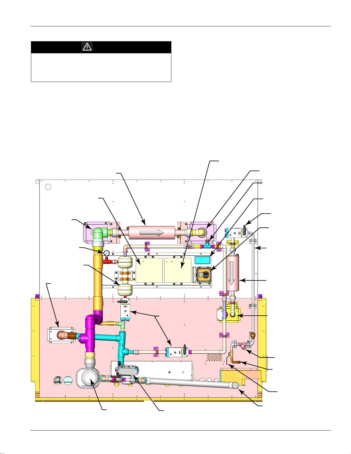
Unit Description
Typical Component Lo ca tio ns
Figure 1 shows a typical RPE unit with the locations of the
major components. Figure 2, page 4 shows a typical RDE unit
Figure 1: Typical Component Locations - RPE Units
with the locations of the major components. These figures are
for reference only. See the certified submittals for actual
specific dimensions.
Figure 2: Component Locations - RDE Units
4 McQuay IM 791-2
Page 5
Condenser Fan Arrangement
Table 2 shows the condenser fan numbering conventions and
locations for each unit size.
Table 2: Condenser Fan Arrangement
Introduction
Unit
Size
076C
089C
100C
110C
130C
140C
150C
Refrig.
Circuit
1
2
1
2
Arrangement
11
21
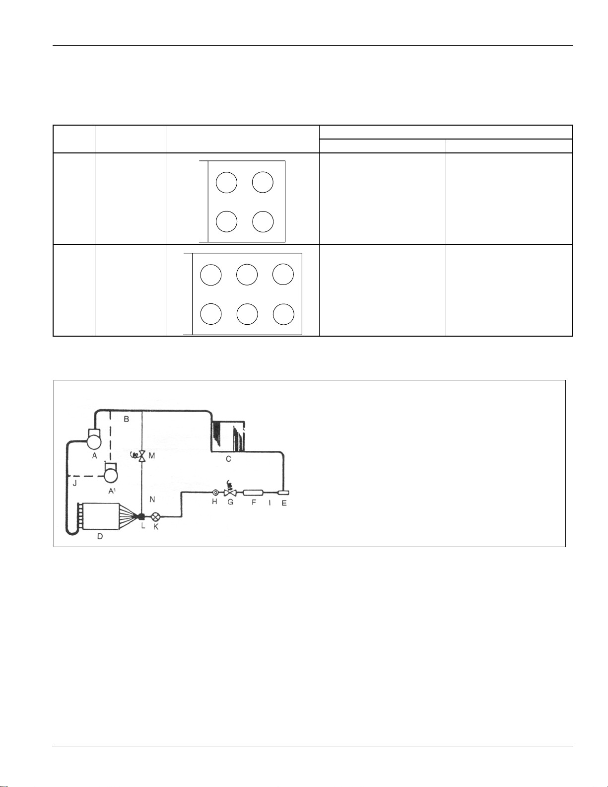
Refrigerant Circuit Schematic
Figure 3: Circuit Schematic
11
21
12
22
12
22
13
23
Fan Control
With VFD Without VFD
11, 21 - Digital
12 - CCB1 - B06
22 - CCB2 - B06
11, 21 - Digital
12 - CCB1 - B06
22 - CCB2 - B06
31 - CCB1 - B07
32 - CCB1 - B07
11, 21 - Digital
21 - CCB2 - B05
12 - CCB1 - B06
22 - CCB2 - B06
11 - CCB1 - B05
21 - CCB2 - B05
12 - CCB1 - B06
22 - CCB2 - B06
13 - CCB1 - B07
23 - CCB2 - B07
Legend
A Compressor
A1 Second Compressor (4 Compressor Units)
B Discharge Line
C Condenser Coil
D Evaporator Coil
E Manual Shut-off Valve
F Filter-Drier
G Liquid Line Solenoid Valve
H Sightglass
I Liquid Line
J Suction Line
K Thermostatic Expansion Valve
L Distributor
M Combination Hot Gas Bypass Control and Solenoid Valve
N Hot Gas Bypass Lines (Optional)
McQuay IM 791-2 5
Page 6

Introduction
Refrigeration Piping
This section presents the unit refrigeration piping diagrams for
the various available configurations. Component numbering
conventions are also shown.
Figure 4: Condenser Piping - 2 Compressors - 2 Circuits (076C - 100C)
1. Discharge Line Service Valve
2. Discharge Muffler
3. Liquid Line Manual Shut-off Valve
4. Suction Line Service Valve
5. Vibration Eliminator
Suction LIne
Circuit 2
Circuit 1
Compressor 2
4
Discharge Line
Circuit 2
Hot Gas
Bypass
Circuit 2
Circuit 1
Liquid Line
Circuit 1
Liquid Line
Circuit 2
With Vibration Eliminators
Compressor 1
Discharge Line
Circuit 1
Suction LIne
Circuit 2
Circuit 1
5
5
3
2
4
Compressor 2
4
3
1
Discharge Line
Circuit 2
2
Hot Gas
Bypass
Circuit 2
Circuit 1
Liquid Line
Circuit 1
Liquid Line
Circuit 2
Compressor 1
3
2
1
3
Without Vibration Eliminators
Discharge Line
Circuit 1
4
6 McQuay IM 791-2
2
Page 7
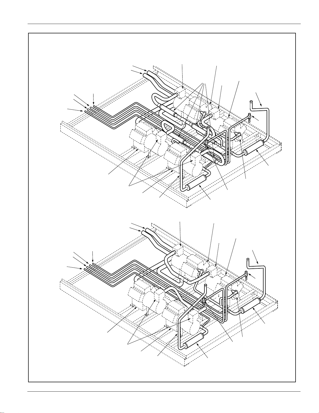
Figure 4. Condenser Piping - 4 Compressors - 4 Circuits (110C - 150C)
4
1. Discharge Line Service Valve
2. Discharge Muffler
3. Liquid Line Manual Shut-off Valve
4. Suction Line Service Valve
5. Vibration Eliminator
Hot Gas
Bypass
Circuit 2
Circuit 1
Liquid Line
Circuit 2
Liquid Line
Circuit 1
Suction LIne
Circuit 2
Circuit 1
Compressor 4
5
Compressor 2
4
Introduction
Discharge Line
Circuit 2
3
2
Compressor 3
With Vibration Eliminators
Hot Gas
Bypass
Circuit 2
Circuit 1
Liquid Line
Circuit 2
Liquid Line
Circuit 1
4
Compressor 1
Suction LIne
Circuit 2
Circuit 1
Discharge Line
Circuit 1
1
3
2
4
Compressor 4
4
Compressor 2
Discharge Line
Circuit 2
3
2
Compressor 3
Without Vibration Eliminators
4
Compressor 1
Discharge Line
Circuit 1
2
1
3
McQuay IM 791-2 7
Page 8
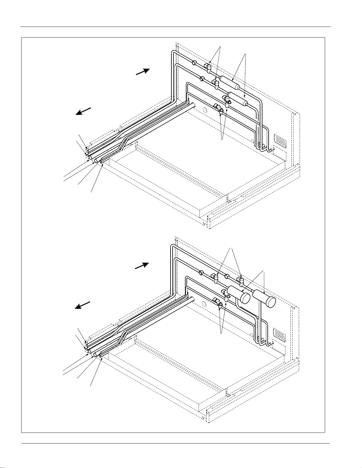
Introduction
Figure 5: Service Compartment Piping
Solid Core Filters
1. Liquid Line Solid Core Filter/Drier
2. Liquid Solenoid Valves
3. Hot Gas Bypass Valve and Solenoids
To Evaporator Coil
Liquid Line
Circuit # 1
Circuit # 2
Suction Line
Circuit # 2
Circuit # 1
Hot Gas Bypass
Circuit # 1
Hot Gas Bypass
Circuit # 2
2
1
To Compressors
3
Replaceable Filters
1. Liquid Line Replaceable Core Filter/Drier
2. Liquid Solenoid Valves
3. Hot Gas Control and Solenoid Valve
To Compressors
To Evaporator Coil
Liquid Line
Circuit # 1
Circuit # 2
Suction Line
Circuit # 2
Circuit # 1
Hot Gas Bypass
Circuit # 1
Hot Gas Bypass
Circuit # 2
2
1
3
8 McQuay IM 791-2
Page 9
Spray System Plumbing with Optional Non-Chemical Water Treatment
WARNING
Failure to maintain and continually provide water
treatment may result in severe equipment damage and
may create biologically hazardous conditions. See
Figure 26 for water connection sizes and locations.
Figure 6: Spray System Piping
NOTE:
The cyclone separator is on a side stream. A hand
valve controls water flow. The hand valve should be
opened until the inlet pressure to the separator is
about 12 psi as determined by the factory-installed
gauge. This will yield about 20 gpm of blowdown
whenever the blowdown solenoid opens.
Dolphin
makeup water
Dolphin sump water
treatment module
Dolphin
sump water
transformer
To Spraybar
transformer
Introduction
To Spraybar
Conductivity sensor
Conductivity controller
Makeup water
control valve
Auto purge controller
Flowmeter
Cyclone seperator
Sump
overflow
Ball valve
actuators
Heat-tape all components
from customer connection
point to makeup water
control valve
Dolphin makeup water
treatment module
Makeup water connection
point to sump tank.
Cleanout
Customer makeup
water connection point
Manual shutoff
Sump Pump
McQuay IM 791-2 9
Freeze protection
valve and actuator
Blow down and drain
Page 10

Introduction
Bleed Off and Water Consumption
Controlled bleed off [or blow down] is required on McQuay
RPE/ RDE units as it should be with all evaporative
condensing products. It involves draining off a portion of the
highly concentrated water from the bottom of the sump and
replacing it with lower concentration make-up water to inhibit
scale. Scale protection is required because the evaporation
process leaves behind solids (scale) that will coat the heat
exchanger surfaces and sump. This reduces the capacity,
efficiency, and life expectancy of the equipment.
Manual bleed off occurs whenever the spray pump operates. A
manual valve adjusts flow and is provided as standard. Refer
to Figure 6. This inevitably bleeds off too much [increased
water costs] or too little [risking scale build up] water.
Automatic bleed off control is superior and usually is provided
with the water treatment system.
Theoretical water consumption required for proper heat
rejection is 1.8 gallons per ton hour. All of this water
evaporates and none goes into the sewer. An additional 0.6 to
0.9 gallons per ton hour (.03 to .05 with McQuay nonchemical water treatment) is also required for make up and
bleed off. The exact amount should be determined by water
Figure 7: Control Locations - RPE Units
analysis. The RPE/ RDE includes a float valve and solenoid
that automatically refills the sump as required.
Bleed off must be handled in accordance with local codes and
normally is drained into the sanitary sewer. Normally, this
water should not be drained onto the roof or into a storm drain.
One possible exception to this is with the McQuay nonchemical water treatment option (consult local codes
carefully). Because most water utilities charge for both intake
and sewer water flows based on intake meter readings, sewer
charges may be reduced if sewer flow is proven to be less than
water intake. McQuay offers both intake and bleed off water
meters to document reduced sewer flow [confirm details with
your local utility]. These meters are not included in the basic
water treatment option.
Control Locations
Figure 7 (RPE Units) and Figure 8, page 11 (RDE Units) show
the locations of the various control components mounted
throughout the units. See Control Locations‚ page 10 for the
locations of control components mounted in control panels.
Additional information is included in Table 3, page 15 and the
Legend‚ page 47.
Return Air
Economizer
Heat
Section
Discharge
Plenum
Section
HL22 (Optional)
LT10 (Optional)
S10, REC10 (Optional)
Service
Section
SD1
(Optional)
Condensor
Section
VM1
(Optional)
Exhaust
Fan
Water Treatment
(Optional)
Oil Pressure Box
Water Pump
Control Box
Space Heater
(Optional)
Water Level
Switches
(WL63, WL64)
Sump Heater (Optional)
Sump Water Temp Sensor
ACT5 (optional)
ACT6 (optional)
OAT
LT11
(Optional)
S11
REC11
OAE
RAE (optional)
10 McQuay IM 791-2
Page 11

Figure 8: Control Locations - RDE Units
(
)
C
ondensor
Section
Introduction
C19,20
(Optional)
Economizer
Return Air
Filter
Section
Heat
Section
SV1, 2
Supply Fan
Discharge
Plenum
Section
OAE
OAT
Service
Section
FS1
(Optional)
LT10 (Optional)
S10, REC10 (Optional)
SD1 (Optional)
Exhaust
Fan
Water Treatment
(Optional)
Water Pump
Control Box
Space Heater
(Optional)
Sump Heater (Optional)
Sump Water Temp Sensor
Oil Pressure Box
Water Level
Switches
(WL63, WL64)
LT11 (Optional)
S11, REC11
SD2
Optional
McQuay IM 791-2 11
Page 12

Introduction
Control Panel Locations
The unit control panels and their locations are shown in the
following figures. These figures show a typical unit
configuration. Specific unit configurations may differ slightly
from these figures depending on the particular unit options.
See Wiring Diagrams‚ page 47 for the Legend and component
description.
Figure 9: Control Panel Locations - Service Compartment
WARNING
Electrical shock can cause severe personal injury or
death.
The control panel must be serviced by trained, experienced
technicians.
Oil
Pressure
Instruments
Control
Panel
Power
Disconnect
12 McQuay IM 791-2
Page 13

Figure 10: Main Control Panel - 076C - 150C
Introduction
See page page 47 for Legend
UP
for Control
Connections
Terminal Block
2 Feet to Floor
Main Disconnect
or Power Block
McQuay IM 791-2 13
Page 14

Introduction
Figure 11: Electric Heat Control Panel - Sizes 075C- 135C
FB31FB32FB33
M31M32M33
FB34FB44
M34M44
FB41FB42FB43
M41M42M43
GLG3
DS3
H53
TB11
• The manual shutter is normally be closed but can be opened
to condition the compartment when service is needed.
Figure 12: Walk-In Service Compartment
Perform Most Refrigerant Service in Comfort, Away
From Compressor Noise
Marine Lights
Exhaust Fan
Optional Unit
Heater
Walk-In Service Compartment
Each unit includes a walk-in service compartment containing
the following:
• Main control panel. See Figure 9, page 12.
• Liquid Line components except the expansion valve.
• Spray pumps, water control valves (except float valves in the
sump) and water supply and sanitary connections. See
Figure 6, page 9.
• Water treatment system (optional).
• Main access door opened from the inside and outside.
• Raised service grate to help protect service personnel against
water and chemical spills.
• Refrigerant Schrader ports are provided on the liquid and
suction lines to allow for easy refrigerant pressure readings,
however, discharge pressure at the compressor must be
measured outside the enclosure.
• Refrigerant charge can be added at the Schrader connections
in the compartment.
• Lights, ventilation fans, manual shutter that can be opened to
allow conditioned air into the plenum and optional unit
heater provide more comfortable servicing.
• An adjustable TC66 thermostat turns on the ventilation fan
when the compartment temperature exceeds 75°F.
• An adjustable integral thermostat runs the unit heater when
the compartment temperature drops to 35°F.
Charging, Suction,
Discharge & Liquid
Schrader Connections
Hot Gas
Bypass
Valves
Solenoid, Sight Glass
& Filter Drier
Raised Floor Grate
and Drain Pan
Space for
Water
Treatment
WARNING
Moving parts and electrical connections in the service
compartment can cause severe personal injury or death.
Cabinet access must be limited to trained, experienced
technicians only.
14 McQuay IM 791-2
Page 15

Controls, Settings, and Functions
Introduction
Table 3 presents a listing of all the unit control devices.
Included in the table are the device symbol, a description of
the device, its function, and any reset information, its location,
Table 3: Controls, Settings , an d Fu nc tions
Symbol
CS1 & 2
DAT
DHL
EFT
FP1, 2
FS1 Freezestat
HP1, 2,
3 & 4
LP1, 2
MCB Main control board Processes input information N/A
MP1–6 Compressor motor
OAE
OAT
PC5 Dirty filter switch Senses filter pressure drop Auto
PC6 Dirty filter switch Senses filter pressure drop Auto
Description Function Reset Location Setting Range Differential Part no.
Switch (toggle),
refrigerant circuit
Discharge air
temperature sensor
Duct high limit
switch
Entering fan air
temperature sensor
Evaporator frost
protection
High pressure
control
Low pressure
control
protector
Enthalpy control
(electromechanical)
Enthalpy control
(electronic)
Outside air
temperature sensor
Shuts off compressor control
circuits manually
Senses discharge air
temperature
Prevents excessive VAV duct
pressures; shuts off fan
Senses entering fan air
temperature
Senses low refrigerant
temperature
Shuts off fans, opens heating
valve, and closes outdoor
damper if low air temperature at
coil is detected
Stops compressor when
refrigerant discharge pressure
is too high
Stops compressor when
suction pressure is too low
(used for pumpdown)
Senses motor winding
temperature, shuts off
compressor on high
temperature.
Notes:
1.Unit size 018C compressors
include internal motor
protector.
2.Unit sizes 020C–036C, circuit
#1 compressors include
internal motor protector (refer
to unit wiring diagram).
Returns outside air dampers to
minimum position when
enthalpy is too high
Returns outside air dampers to
minimum position when outside
air enthalpy is higher than
return air empalthy (use RAE)
Senses outside air temperature N/A N/A N/A 060004705
N/A
N/A
Auto
N/A
N/A
Auto Heating section
Manual
(relay
latched)
Auto Compressor
Auto at
3400
ohms
Auto
Auto
any device setting, any setting ranges, differentials, and the
device part number.
Main control
panel
Discharge air
section
Main control
panel
Inlet of supply
fan
Return bends of
evaporative coil
Compressor
Main control
box
Compressor
junction box
Economizer
section
Economizer
section
First filter
section
Final filter
section
N/A N/A N/A 01355000
N/A N/A 060004705
3.5" w.c
(871.8 Pa)
N/A N/A 060004705
Opens at
30°F
Closes at
45°F
38°F (3°C)
or as required
See
page 105.
See
page 105.
N/A N/A N/A 060006101
9 K–18 K
ohms
“B” or as
required
Fully CW past
“D”
(when used
with RAE)
As required
As required
0.05–5.0" wc
(12.5–1245.4
Pa)
N/A N/A 072501901
35°F–45°F
(2°C–7°C)
N/A
N/A
700 ohms cold N/A 044691509
A–D
A–D N/A 049262201
.05-5" wc
(12.5–1245.4
Pa)
.05-5" wc
(12.5–1245.4
Pa)
.05" wc
(12.5 Pa),
fixed
12°F (7°C),
fixed
100 psi
(689 kPa)
25 psi
(172 kPa)
Temperature:
3.5°F (2°C)
Humidity:
5% fixed
.05" wc
(12.5 Pa)
.05" wc
(12.5 Pa)
065493801
065830001
047356120
047356111
030706702
065493801
065493801
McQuay IM 791-2 15
Page 16

Introduction
Table 3: Controls, Settings , an d Fu nc tions (continued)
Symbol
PC7
PS1, 2 Pumpdown switch
RAE
RAT
SD1
SD2
SPS1
SPS2
SUMP
HTR
SV1, 2
SV5, 6
SV61,
62
SV63 Solenoid Valve
SWT Sump Water Temp
S1 System switch
S7
TC66 Temperature
WL63 Switch, Water Level
WL64 Switch, Low Water Maintains proper water level N/A Sump Holding
Description Function Reset Location Setting Range Differential Part no.
Airflow proving
switch
Return air enthalpy
sensor
Return air
temperature sensor
Smoke detector,
supply air
Smoke detector,
return air
Static pressure
sensor duct #1
Static pressure
sensor duct #2
Static pressure
sensor: building
(space) pressure
Sump Water Heater ,
Evap Condenser
Solenoid valve
(liquid line)
Solenoid valve
(hot gas bypass)
Solenoid Valve
(Water Fill - Evap
Cond)
(Sump Drain - Evap
Cond)
Sensor
ON-OFF-AUTO
switch
Control - Evap Cond
Exhaust Fan
Sump Fill
Senses supply fan pressure to
prove airflow
Used to manually pump down
compressor
Used to compare return air
enthalpy to outside air enthalpy
(used with OAE)
Senses return air temperature N/A
Initiates unit shutdown if smoke
is detected
Initiates unit shutdown if smoke
is detected
Converts static pressure
signals to voltage signals
Converts static pressure
signals to voltage signals and
sends them to MicroTech II
controller
Converts static pressure
signals to voltage signals.
Controls Wa ter Temp in the
Evap Condenser Sump
Closes liquid line for
pumpdown
Closes hot gas bypass line for
pump-down
Open when sump water level is
low to add water
Opens to drain sump N/A Service
Sensor for freeze and head
pressure control
Shuts off entire control circuit
(except crankcase heaters)
Used to manually switch unit N/A
Sequences the vestibule
exhaust fan
Maintains proper water level N/A Sump Holding
Auto
N/A
N/A
Manual
Manual
N/A
N/A
N/A
N/A
N/A
N/A Service
N/A Sump Holding
N/A
N/A Service
Supply fan
section
Condenser
control box
Economizer
section
Return air
section
Discharge air
section
Return air
section
Main control
box
Main control
box
Main control
box
Sump Holding
Tank
Condenser
section
Condenser
section
Compartment
Compartment
Tank
Main control
box
Main control
box
Compartment
Tank
Tank
.10" wc (25
Pa)
N/A N/A N/A 01355000
N/A N/A N/A 049262202
N/A N/A 060004705
N/A N/A N/A 04925001
N/A N/A N/A 04925001
N/A
N/A
N/A
N/A N/A N/A
N/A N/A N/A 111011001
N/A N/A N/A
N/A N/A N/A
N/A N/A N/A See parts
N/A N/A N/A 001355000
N/A N/A N/A
N/A N/A N/A
N/A N/A N/A See parts
N/A N/A N/A See parts
.05-5" wc
(12.5–1245.4
Pa)
0–5" wc
(0–1245.4 Pa)
1–6 VDC out
0–5" wc
(0–1245.4 Pa)
1–6 VDC out
-025–0.25" wc
(-62.3–62.3 Pa)
1–5 VDC out
.05" wc
(12.5 Pa),
fixed
N/A 049545007
N/A 049545007
N/A 049545006
060015801
See parts
See parts
See parts
See parts
See parts
See parts
catalog
catalog
catalog
catalog
catalog
catalog
catalog
catalog
catalog
16 McQuay IM 791-2
Page 17
Mechanical Installation
S
d
p
The installation of this equipment must be in accordance with
the regulations of authorities having jurisdiction and all
applicable codes. It is the responsibility of the installer to
determine and follow the applicable codes.
WARNING
Improper installation, adjustment, alteration se r v ic e or
maintenance can cause personal inju ry or death.
Read and understand this Installation and Maintenance
manual thoroughly before installing or servicing this
equipment.
Note: Low head pressure may lead to poor, erratic refrigerant
feed control at the thermostatic expansion valve. The
units have automatic control of the condenser fans which
should provide adequate head pressure control down to
50°F (10°C). The system designer is responsible for
assuring the condensing section is not exposed to
excessive wind or air recirculation.
WARNING
Sharp edges and coil surfaces can cause personal
injury. Avoid contact with them.
Installation and maintenance must be performed only by
trained and experienced personnel familiar with local codes
and regulations.
WARNING
Sharp edges on sheet metal, screws and clips can cause
personal injury.
This equipment must be installed and operated only by
experienced trained personnel.
Mechanical Installation
Receiving Inspection
When the equipment is received, check all items against the
bill of lading to be sure all crates and cartons have been
received. If the unit has become dirty during shipment
(winter road chemicals are of particular concern), clean it
when received.
Inspect all units for damage when received. Report all
shipping damage to the carrier and file a claim. In most cases,
equipment is shipped F.O.B. factory and claims for freight
damage should be filed by the receiver.
The unit nameplate should be checked before unloading the
unit to make sure the voltage complies with the power supply
available.
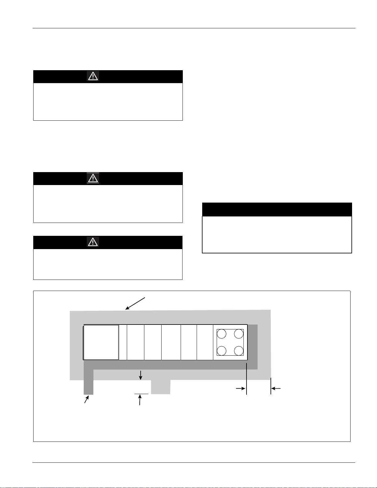
Unit Clearances
Service Clearance
Allow service clearance approximately as indicated in
Figure 13. Also, a roof walkway should be provided to the
rooftop unit and along at least the two sides of the unit that
provide access to most controls and serviceable components.
NOTICE
On units with side discharge, access to plenum mounted
components becomes difficult once ductwork is installed.
Installer must provide access in the ductwork for plenum
mounted controls.
Figure 13: Service Clearances Side Discharge
72"
4 sides except as indicated
ABCDEFG
24"
Roof Walkway
Adjacent to Cooling Coil,
Heat, and Supply
Fan Sections.
ervice Clearance on
Legend:
A = Return Air Section
B = Filter Section
C = Cooling Section
D = Cooling/Supply Fan Section
E = Heat Section
F = Discharge Plenum Section
G = Service Com
artment
72" Clearance to
end of unit or en
of outside hood
McQuay IM 791-2 17
Page 18

Mechanical Installation
Maxi
All
Figure 14: Side Discharge
V entilation Clearance
Following are minimum ventilation clearance
recommendations. The system designer must consider each
application and provide adequate ventilation. If this is not
done, the unit will not perform properly.
Unit(s) surrounded by a screen or a fence:
1 The bottom of the screen or fence should be at least 1 ft.
(305 mm) above the roof surface.
2 The distance between the unit and a screen or fence should
be as described in Service Clearance‚ page 17. See also
Figure 13, page 17.
3 The distance between any two units within a screen or
fence should be at least 120" (3048 mm).
Unit(s) surrounded by solid walls:
1 If there are walls on one or two adjacent sides of the unit,
the walls may be any height. If there are walls on more than
two adjacent sides of the unit, the walls should not be
higher than the unit.
2 The distance between the unit and the wall should be at
least 96" (2438 mm) on all sides of the unit.
3 The distance between any two units within the walls should
be at least 120" (3048 mm). Do not locate outside air
intakes near exhaust vents or other sources of contaminated
air.
If the unit is installed where windy conditions are common,
wind screens should be installed around the unit, maintaining
the clearances specified (see Figure 15). This is particularly
important to prevent blowing snow from entering outside air
intakes, and to maintain adequate head pressure control when
mechanical cooling is required at low outdoor air
temperatures.
Overhead clearance
1 Unit(s) surrounded by screens or solid walls must have no
overhead obstructions over any part of the unit.
2 The area above the condenser must be unobstructed in all
installations to allow vertical air discharge.
3 The following restrictions must be observed for overhead
obstructions above the air handler section (see Figure 15):
a There must be no overhead obstructions above the
furnace flue, or within 9" (229 mm) of the flue box.
b Overhead obstructions must be no less than 2" (51 mm)
above the top of the unit.
c There must be no overhead obstructions in the areas
above the outside air and exhaust dampers that are
farther than 24" (610 mm) from the side of the unit.
Figure 15: Overhead Clearance
mum
owable
9" (229mm) Min to Flue Box
Typical All Sides
24" (610 mm)
Maximum
2" (51mm)
Top of Unit
To O verhead
Obstruction
Overhead Canopy Area
Flue Box
18 McQuay IM 791-2
Page 19

Mechanical Installation
Roof Curb Assembly and Installation
The roof curb and unit must be located on a portion of the roof
that can support the weight of the unit. The unit must be
supported to prevent bending or twisting of the machine.
If building construction could allow the transmission of sound
and vibration into the occupied space, the unit should be
located over a non-critical area. It is the responsibility of
the system designer to make adequate provisions for noise
and vibration in the occupied space.
The curb and unit must be installed level to allow the
condensate drain to flow properly.
Integral supply and return air duct flanges are provided with
the RPE/RDE roof curb, allowing connection of ductwork to
the curb before the unit is set. The gasketed top surface of the
duct flanges seals against the unit when it is set on the curb.
These flanges must not support the total weight of the
ductwork. Refer to Installing Ductwork‚ page 32 for details on
duct connections. It is critical that the condensate drain side of
the unit be no higher than the opposite side.
Assembly of a typical RPE/RDE roof curb is shown in
Figure 17, page 21. Parts A through K are common to all units
having bottom return openings. Depending on the unit length,
Parts L and M may be included with the roof curb kit to create
the correct overall curb length.
RPE/RDE Assembly instructions
Refer to Figure 17, page 21.
1 Set curbing parts A through K per dimensions shown over
roof opening or on a level surface. Note location of return
and supply air openings.
2 If applicable, set other curbing parts (D, L, M, etc.) in place
making sure that the orientation complies with the
assembly instructions. Check alignment of all mating bolt
holes.
3 Bolt curbing parts together using fasteners provided.
Tighten all bolts finger tight.
4 Square entire curbing assembly and securely tighten all
bolts.
5 Position curb assembly over roof openings. Curb must be
level from side to side and over its length. Check that top
surface of the curb is flat with no bowing or sagging.
6 W eld curbing in place. Caulk all seams watertight. Remove
backing from 0.25" (6 mm) thick x 1.50" (38 mm) wide
gasketing and apply to surfaces shown by notes.
7 Flash curbing into roof as shown in Detail “B”.
8 Parts E and F are not required on units with no return shaft
within the curb perimeter.
9 Parts G and H are not required on units with no supply shaft
within the curb perimeter.
McQuay IM 791-2 19
Page 20

Mechanical Installation
Figure 16: RPE/RDE Roof Curb Assembly
RDE & RPE 076-100
D
SA
OPENING
OPENING
N
P
C
RA
SEE FIGURE "A"
G
F
E
F
R
Q
H
J
K
L
K
M
B
RDE & RPE 110-150
G
F
E
C
RA
OPENING
D
SA
OPENING
R
Q
H
K
L
L
K
F
N
P
SEE FIGURE "A"
J
M
B
B
M
Dim 076-100C 110-150C
J
100.00 100.00
84.00 60.00
62.00 62.00
38.00 46.00
87.00 87.00
1.50 1.50
6.80 6.80
81.00 81.00
7.50 7.50
5.00 5.00
8.00 8.00
2.00 2.00
4.00 4.00
1.50 1.50
78.80 78.80
B
C
D
E
F
G
H
K
L
M
N
P
Q
R
20 McQuay IM 791-2
Page 21

Figure 17: RPE/RDE Roof Curb Assembly
Using remaining side supports
in this area, align lengths on
opposite sides of assembly
and install a cross support
at each side.
Equal Length
Side Supports
See Detail "A"
B
Mechanical Installation
Condenser
Section Support
(1 of 2 shown)
A
A
38.8"
B
Return
Air
85"
62.8"
Section B-B
Section A-A
2
1
2
5
4
9
10
6
7
10
3
9
6
8
4
1. Unit Base
2. Curb Gasketing
3. 2 x 4 Nailer Strip
4. Galvanized Curb
5. Duct Support
6. Cant Strip (not furnished)
7. Roofing Material (not furnished)
8. Rigid Insulation (not furnished)
9. Counter flashing (not furnished)
10. Flashing (not furnished)
2
2
3
5
4
1
9
10
6
7
8
McQuay IM 791-2 21
Page 22

Mechanical Installation
Post and Rail Mounting
When mounting by post and rail, the structural support should
be run the full length of the unit. Locate the structural member
at the base of the unit as shown in Figure 18 assuring the
shaded area is well supported by the structural member.
CAUTION
The unit must be level side to side and over the entire
length. Equipment damage can result if the unit is not level.
If resilient material is placed between the unit and the rail,
insert a heavy steel plate between the unit and the resilient
material to distribute the load. Properly seal cabinet
penetrations (electrical, piping, etc.) to protect against
moisture and weather.
Figure 18: Post and Rail Mounting
max
4 Provide adequate protection from vandalism, mechanical
contact, etc.
5 Securely close the doors.
6 If there are isolation dampers, make sure they are properly
installed and fully closed to prevent the entry of animals
and debris through the supply and return air openings.
7 Cover the supply and return air openings on units without
isolation dampers.
Figure 19 shows an example of the rigging instruction label
shipped with each unit.
WARNING
Use all lifting points. Severe personal injury and
property damage can result from improp er lifting
adjustment.
Figure 19: Rigging and Handling Instruction Label
Rigging and Handling Instructions
Unit has either four or six lifting points (four-point shown below).
Caution: All lifting points must be used.
Rigging cables must be at least as long as distance "A".
Note:
*Rail cannot extend beneath the unit more than 5" (127 mm) or it will interfere
with duct and electrical connections.
Rigging and Handling
Lifting brackets with 2" (51 mm) diameter holes are provided
on the sides of the unit.
Use spreader bars, 96" to 100" (2438 to 2540 mm) wide to
prevent damage to the unit cabinet. Avoid twisting or uneven
lifting of the unit. The cable length from the bracket to the
hook should always be longer than the distance between the
outer lifting points.
If the unit must be stored at the construction site for an
intermediate period, these additional precautions should be
taken:
1 Make sure to support the unit well along the length of the
base rail.
2 Make sure to level the unit
(no twists or uneven ground surface).
3 Provide proper drainage around the unit to prevent flooding
of the equipment.
Caution:
Lifting points may not
be symmetrical to center of
gravity of unit. Balast or unequal
Lift Only As Indicated
cable lengths may be required
Lifting Points
Refer to Figure 20 and the following calculations to determine
whether a four or six point lift is required.
X= Distance from the entering air end of the unit (or shipping
section) to the first lifting lug in the direction of air flow.
For all units or shipping sections with outdoor air/return air
options, X= 48"
For shipping sections without outdoor air/return air options,
X= 0
Y= distance from condenser or leaving air end of unit to the
last lifting lug.
For all units or shipping sections with condensers, Y= 21.5
(sizes 76-100) or Y= 60.2 (sizes 110-150).
For all units or shipping sections without condensers, Y=0
Z= Total base rail length of the unit. Note: Z excludes hoods
and overhung parts extending past base rails of the unit.
22 McQuay IM 791-2
Page 23

Mechanical Installation
A= Z-X-Y
If A<288", 4-point lift is sufficient
If A>288", 6-point lift is required
B= Distance from first lifting lug to middle lifting lug on units
with 6-point lift.
B= A/2 +/- 48" Note: Middle lifting lug may be installed on
either side of the midpoint to avoid interference with
condensate drains.
Figure 20: Unit Type RPE/RDE Lifting Points
Figure 21: RPE/RDE Factory Split at Supply Fan Section
McQuay IM 791-2 23
Page 24

Mechanical Installation
Reassembly of Split Units
Although RoofPak units typically ship from the factory as
complete units, they may be split at the factory.
The RPE/RDE unit may ship from the factory as two pieces,
split at the supply fan bulkhead, to be recoupled together on
the roof. This configuration would be ordered if shipping
length or weight limitation prevented a packaged RPE/RDE
from being ordered. Splitting at the fan has the advantage of
leaving all factory refrigerant piping intact so field evacuation
and charging is not required.
A single nameplate is attached to the air handler section and
power is fed to both sections through the main control box, as
it would be in a non-split RPE/RDE unit.
RPE/RDE Factory Split at Fan
Field reassembly of an RPE/RDE unit that has shipped split at
the fan takes place in two phases:
Phase 1 - Setting the Sections and Cabinet
Reassembly
The steps required to set the unit and reassemble the cabinet
are shown in Figure 22, Figure 23, and Figure 24, page 25.
The following items should be noted:
1 Top cap and plywood covers must be removed before the
sections are set together, but the steel retainer clips must be
left in place to secure the bulkhead. Refer to Step 1 and
Figure 22.
2 Both sections must be carefully lowered into place to make
sure that the roof curb engages the recesses in the unit base.
3 All seams at the split must be caulked watertight after
recoupling the sections, as shown in Step 3 and Figure 23,
page 25.
WARNING
Improper installation can cause severe equipment
damage, personal injury or death.
Connect the power block correctly and maintain proper
phasing.
When reconnection of the power wires is complete, the inner
raceway cover in the blank or heat section must be reinstalled.
Figure 24, page 25 shows a typical installation of the raceway
cover. If the unit is equipped with a fan diffuser, install as
shown in Figure 24.
Control harnesses can be run by removing the external
raceway covers on either side of the unit split. The excess
harness length can be removed from the external raceway on
the DX side of the split, routed along the raceway through the
bushed hole in the fan section and into the junction box where
control wiring terminal blocks are provided for reconnection.
All electrical connections should be made per the unit's
electrical schematics. Reinstall the external raceway covers
after routing of the control wires is complete.
1 Prepare the units for reassembly as shown in Figure 22.
Figure 22: RPE/RDE Split at Fan Reassembly - Step 1
R e m o v e p l y w o o d a n d r e t a i n i n g
R e m o v e t o p c a p a n d
s a v e f o r s t e p 3
a n g l e s f r o m u n i t a n d d i s c a r d
D i s c h a r g e e n
d o f U n i t
Phase 2 - Reconnecting Power and Control Wiring
The DX coil/condenser section contains power and control
harnesses which have their excess length in the blank or heat
section that is normally immediately downstream of the fan.
Once the sections are physically reconnected, the ends of the
F a n e n d o f U n i t
power harness are fed back through the unit base into the
junction box, per the unit’s electrical schematics.
24 McQuay IM 791-2
2
Set fan end of unit and discharge end of unit in place.
3 Caulk and install parts as shown in Figure 23.
R e m o v e s c r e w s o n f a n p a n e l , b u t
l e a v e r e t a i n e r c l i p s i n p l a c e ;
s a v e s c r e w s f o r
S t e p 3 .
Page 25

Mechanical Installation
ovided
Figure 23: Split at Fan Reassembly - Step 3
Reinstall Top Cap
Saved from Step 1
Caulk Ends of
Splice Cap
Splice Cover
Provided
Install
#10 Screws
Provided
Figure 24: RPE Split at Fan Reassembly - Step 4
Install Screws (.250-20 x .75)
Saved from Step 1
Nut
Clip-on
Pr
4
Make electrical connections and reinstall Inner Raceway
Cover as shown in Figure 24.
McQuay IM 791-2 25
Page 26

Mechanical Installation
Condensate Drain Connection
The unit is provided with a 1.5" male NPT condensate drain
connection. Refer to certified drawings for the exact location.
The unit and drain pan must be level side to side and a P-trap
must be installed for proper drainage.
RPE units may have positive or negative pressure sections.
Traps should be used in both cases, with care given to negative
pressure sections. In Figure 25, page 26, dimension “A”
should be a minimum of 8" (203 mm). So the cabinet static
pressure does not blow or draw the water out of the trap and
cause air leakage, dimension A should be two times the
maximum static pressure encountered in the coil section in
inches w.c.
Drainage of condensate directly onto the roof may be
acceptable; refer to local codes. A small drip pad of stone,
mortar, wood or metal be should be provided to protect the
roof against possible damage.
If condensate is to be piped into the building drainage system,
the drain line should be pitched away from the unit at a
minimum of 1/8" per foot. The drain line must penetrate the
roof external to the unit. Refer to local codes for additional
requirements. Sealed drain lines require venting to provide
proper condensate flow.
Where the cooling coils have intermediate condensate pans on
the face of the evaporator coil, copper tubes near both ends of
the coil provide drainage to the main drain pan. Check that the
copper tubes are in place and open before the unit is put into
operation.
Because drain pans in any air conditioning unit will have some
moisture in them, algae, etc. will grow. Periodic cleaning is
necessary to prevent this buildup from plugging the drain and
causing the drain pan to overflow. Also, the drain pans should
be kept clean to prevent the spread of disease. Cleaning must
be performed by qualified personnel.
WARNING
Clean drain pans regularly. Growth in uncleaned drain
pans can cause disease.
Cleaning must be done by trained, experienced personnel.
Figure 25: Condensate Drain Connection
S e e V i e w " A "
C o p p e r T u b e
( o n e e a c h e n d o f c o i l )
S t a t i c P r e s s u r e " P "
4 " ( 1 0 2 m m )
M i n i m u m
" A "
8 " ( 2 0 3 m m )
M i n . o r 2 x " P "
( i n . w . o . )
D r a i n P a n
N o t e : D r a i n l i n e m u s t
n o t b e r u n h i g h e r
t h a n t h i s l e v e l
M i n i m i z e T h i s
e n s i o n
D i m
Unit Piping
Gas Piping
See the “Installation” section of the gas-fired furnace
installation manual, Bulletin No. IM684 or IM685.
Supply Water
City water must be piped into the service section of the unit.
Install a manual shutoff valve to facilitate service of the unit.
Provisions have been made to pipe through the floor of the
service section within the curb. If the unit will be exposed to
low outdoor air conditions, care must be taken to prevent
freeze damage to this piping.
The service section has an optional heater to minimize freeze
problems during cold weather. Verify that this heater functions
before filling the unit. A sump heater option is also offered that
includes heat tape on the pressure side of the float controlled
fill valve, plus an extra 8 feet of heat tape to protect field
connections inside the service compartment.
If the unit is mounted on post and rail structure, pipe will be
exposed to outdoor conditions and will need to be heat taped
or drained manually during the winter season.
26 McQuay IM 791-2
Page 27

Mechanical Installation
Drain Water
A drain and bleed off connection is also located in the service
section of the unit. Since this water will contain water
treatment chemicals, local codes may require connection to the
sanitary sewer. The freeze warning for supply water also
applies to drain water piping.
Figure 26: Unit Piping Knockout Locations
Discharge
Air
Opening
A
7.87
6.88
9.26
DETAIL A
SCALE 1 : 9
4.75
2.25
6.75
4.75
Note: Make sure that a service compartment heater and
especially a sump heater or some type of freeze
protection have been provided if freezing conditions are
expected.
Walk-in
Vestibule
CONTROL
WIRING
.88" KNOCKOUT
(3)
B
C ondensing
SUPPLY
WATER
3.0" KNOCKOUT
(.75" COPPER
CONN ECTION)
Unit
7.87
26.50
DETAIL B
SCALE 1 : 9
21.50
3.0" KNOCKOUT
(2)
Water Treatment
WARNING
Failure to maintain and continually provide water
treatment will result in severe equipment damage and
may create biologically hazardous conditions.
Water treatment, whether ordered as an option on the unit or
purchased separately, must be properly installed and started
before starting the unit. Failure to do so will result in scale
build up on the condenser tubes with a resulting loss in heat
rejection capacity. In severe cases, it may become impossible
to operate the compressors. In addition, untreated cooling
tower water can be a source for airborne disease.
Proper water treatment must include the following minimum
features:
• Bleed Off
• Scale and corrosion inhibitor chemical treatment
• Biocide chemical treatment
See Catalog 219 for information on the optional McQuay
supplied water treatment systems.
POWER WIRES
72.00
(REFERENCE)
DRAIN
WATER
3.0" KNOCKOUT
(2.0" PVC C ONNEC TION)
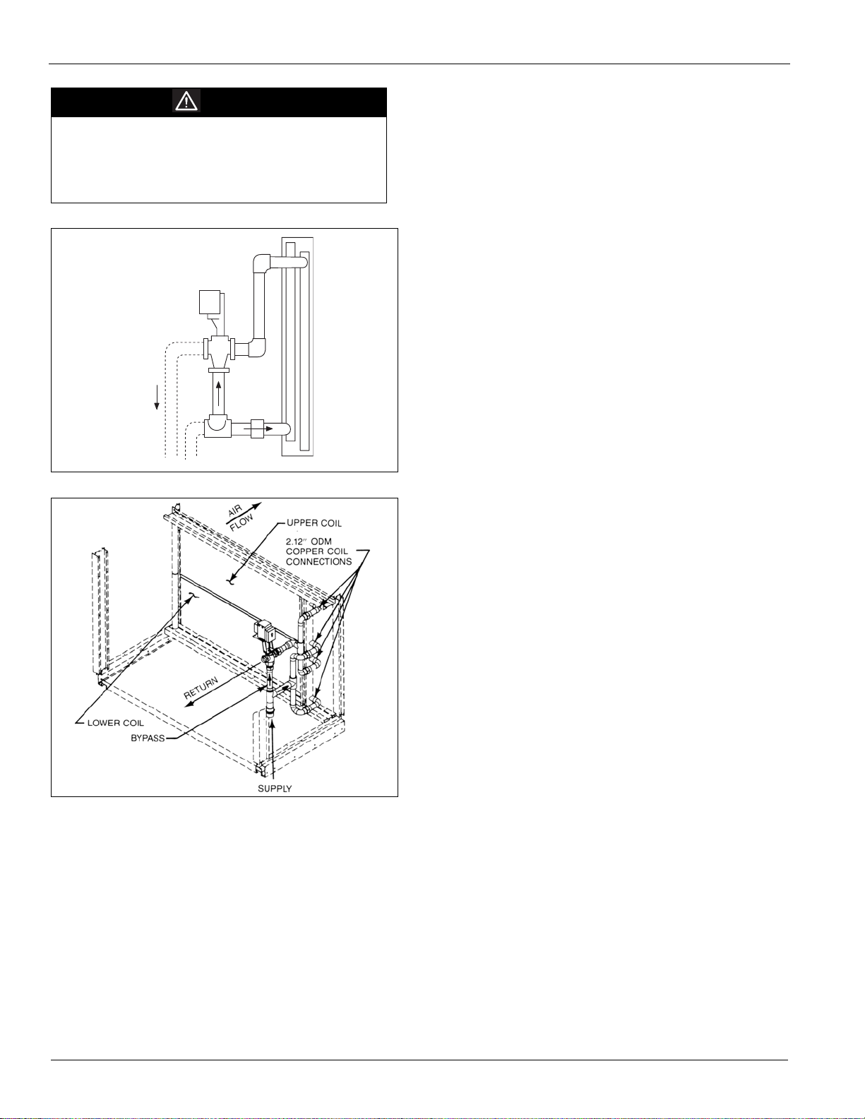
Hot Water Coil Piping
Hot water coils either are provided without valves for field
piping or are piped with three-way valves and actuator motors.
Note: If the unit is equipped with an iron valve, connecting to a
copper piping system will likely cause galvanic corrosion to
occur and the valve will not last. All coils have vents and
drains factory installed.
Hot water coils are not normally recommended for use with
entering air temperatures below 40°F (4°C). No control system
can guarantee a 100% safeguard against coil freeze-up. Glycol
solutions or brines are the only freeze-safe media for operation
of water coils at low entering air temperature conditions.
When no factory piping or valve is included, the coil
connections are 2-1/8" copper (two supply and two return).
With the factory piping and valve package, field piping
connections are the same NPT size as the valve with female
threading (see Figure 27, page 28).
Refer to the certified drawings for the recommended piping
entrance locations. All piping penetrations must be sealed to
prevent air and water leakage.
Note: The valve actuator spring returns to a stem down
position upon power failure. This allows full flow through
the coil.
McQuay IM 791-2 27
Page 28
Mechanical Installation
CAUTION
Coil freeze possible. Possible equipment damage.
Carefully read and follow instructions for mixing antifreeze
solution. Some products will have higher freezing points in
their natural state than when mixed with water. The freezing
of coils is not the responsibility of McQuay International.
Figure 27: Hot Water Valve Package
R e t u r n
Figure 28: Hot Water Heat Section (Factory Valve/Piping)
B y p a s s
S u p p l y
Refer to the certified drawings for the recommended piping
entrance locations. All piping penetrations must be sealed to
prevent air and water leakage.
Note: The valve actuator spring returns to a stem up position
upon power failure. This allows full flow through the coil.
Steam Piping Recommendations
1 Be certain that adequate piping flexibility is provided.
Stresses resulting from expansion of closely coupled piping
and coil arrangement can cause serious damage.
2 Do not reduce pipe size at the coil return connection. Carry
return connection size through the dirt pocket, making the
reduction at the branch leading to the trap.
3 Install vacuum breakers on all applications to prevent
retaining condensate in the coil. Generally, connect the
vacuum breaker between the coil inlet and the return main.
However, if the system has a flooded return main, the
vacuum breaker should be open to the atmosphere and the
trap design should allow venting of large quantities of air.
4 Do not drain steam mains or takeoffs through coils. Drain
mains ahead of coils through a steam trap to the return line.
5 Do not attempt to lift condensate.
6 Pitch all supply and return steam piping down a minimum
of 1" (25 mm) per 10 feet (3 m) of direction of flow.
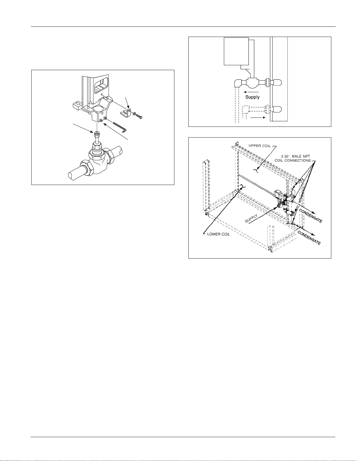
Steam Coil Piping
Steam coils either are provided without valves for field piping,
or are piped with two-way valves and actuator motors.
The steam coil is pitched at 1/8" (3 mm) per foot (305 mm) to
provide positive condensate removal. When no factory piping
or valve is included, the coil connections are 2.5" male NPT
iron pipe.
With the factory piping and valve package, the field supply
connection is the same NPT size as the valve with female
threading (see Figure 30, page 29).
Steam Trap Recommendations
1 Size traps in accordance with manufacturers'
recommendations. Be certain that the required pressure
differential will always be available. Do not undersize.
2 Float and thermostatic or bucket traps are recommended for
low pressure steam. Use bucket traps on systems with onoff control only.
3 Locate traps at least 12" (305 mm) below the coil return
connection.
4 Always install strainers as closely as possible to the inlet
side of the trap.
5 A single tap may generally be used for coils piped in
parallel, but an individual trap for each coil is preferred.
Steam Coil Freeze Conditions
If the air entering the steam coil is below 35°F (2°C), note the
following recommendations:
1 1.5 psi (34.5 kPa) steam must be supplied to coils at all
times.
2 Do not use modulating valves. Control should be by means
of face and bypass dampers.
3 As additional protection against freeze-up, the tap should
be installed sufficiently far below the coil to provide an
adequate hydrostatic head to provide removal of
condensate during an interruption on the steam pressure.
Estimate 3 ft. (914 mm) for each 1 psi (7 kPa) of trap
differential required.
28 McQuay IM 791-2
Page 29
Mechanical Installation
4 If the unit is to be operated in environments with possible
freezing temperatures, an optional freezestat is
recommended. See Freeze Protection‚ page 68 for
additional information.
Figure 29: Valve Assembly
S t e m C l i p
S t e m
S e t s c r e w s
Figure 30: Steam Valve Package
Condensate
Figure 31: Steam Heat Section (Factory Valve/Piping)
McQuay IM 791-2 29
Page 30

Mechanical Installation
Damper Assemblies
The optional damper assemblies described in this section are
provided with manually adjustable linkages, or may be shipped
with factory installed actuators and linkages.
Economizer Dampers
Outside air intake is provided on both sides of the unit, and the
return air path is at the center of the damper set. As the single
actuator modulates the outside air dampers open, the return air
dampers close. Exhaust air exits the unit through the gravity
relief dampers provided at the end of the economizer section.
The outside air return air damper assembly (economizer)
comes with manually adjustable linkage. This adjustable
linkage can also be used for connection of a damper operator.
The damper is set so that the crankarm moves through a 90degree angle to bring the economizer dampers from full open
to full close. Mechanical stops have been placed in the
crankarm mounting bracket. Do not remove stops. If the
crankarm is driven past the stops, damage to the linkage or
damper will result. The unit will ship with a shipping bolt
securing the linkage crankarm. Remove shipping bolt before
use.
Figure 32: Damper Adjustment
O u t s i d e
O u t s i d e
O p t i o n a l R e t u r n A i r F a n
A i r
A i r
E c o n o m i z e r
S h a f t . 5 0 0 D i a .
x 1 . 5 0 L o n g
O A
O p e n
9 0 °
S t r o k e
. 7 5
. 2 5
3 . 0 0
O A
C l o s e d
Note: For good airflow control, adjust linkages so damper
blades do not open beyond 70 degrees. Opening a
damper blade beyond 70 degrees has little effect on its
airflow.
Do not “overclose” low leak damper blades. The edge
seal should just lightly contact the adjoining blade. The
blades will lock up if they are closed so far the seal goes
over center.
30 McQuay IM 791-2
Page 31

Mechanical Installation
Intake Hood Damper (0 to 100% outside air)
Units requiring 100% outside air are provided with a rain hood
and dampers which may be controlled by a single actuator. The
actuator provides two-position control for opening the
dampers fully during unit operation and closing the dampers
during the off cycle. No unit mounted exhaust dampers are
provided.
Intake Hood Damper (0 to 30% outside air)
These dampers are intended to remain at a fixed position
during unit operation, providing fresh air quantities from 0 to
30% of the total system airflow, depending on the damper
setting. This setting is made at the linkage rod on units with
manually adjustable linkages.
On units provided with MicroTech II controls, the damper
position may be set at the controller keypad. During unit
operation, the two-position actuator drives the damper to the
position set on the keypad. During the off cycle, the damper is
automatically closed.
No unit mounted exhaust dampers are provided with this
option.
Figure 33: Intake Hood Damper Adjustment
Figure 34: Typical Damper Linkage Bar - Size 015C - 040C
Shown
A i r f l o w
3 . 1 5 " ( 8 0 m m )
M a x . S t r o k e o f
D a m p e r L i n k a g e B a r
Cabinet Weatherproofing
This unit ships from the factory with fully gasketed access
doors and cabinet caulking to provide weather resistant
operation. After the unit has been set in place, all door gaskets
should be inspected for shipping damage and replaced if
necessary.
S h a f t . 5 0 0 D i a .
x 1 . 5 0 L o n g
O A
O p e n
9 0 °
S t r o k e
. 7 5
The unit should be protected from overhead runoff from
overhangs or other such structures.
Field assembled options such as external piping or vestibules
must be recaulked per the installation instructions provided
with the option.
O A
C l o s e d
. 2 5
3 . 0 0
McQuay IM 791-2 31
Page 32

Mechanical Installation
Installing Ductwork
On bottom-supply/bottom-return units, the installing
contractor should make an airtight connection by attaching
field fabricated duct collars to the bottom surface of either the
roof curb's duct flange or the unit's duct opening if a McQuay
roof curb is not used. Do not support the total weight of the
ductwork from the unit or these duct flanges. Refer to
Figure 35.
Units with optional back return or side discharge have duct
collars provided. The discharge duct collars on a side
discharge unit are exposed by removing the plenum section
access door and the door gasketing.
Use flexible connections between the unit and ductwork to
avoid transmission of vibration from the unit to the structure.
Figure 35: Installing Ductwork
U n i t D u c t O p e n i n g
Design ductwork per ASHRAE and SMACNA
recommendations to minimize losses and sound transmission.
Where return air ducts are not required, connect a sound
absorbing T or L to the unit return to reduce noise transmission
to the occupied space.
Ductwork exposed to outdoor conditions must be built in
accordance with ASHRAE and SMACNA recommendations
and local building codes
.
NOTICE
Installer must provide access in the ductwork for plenum
mounted controls.
On units with side discharge, access to plenum mounted
components becomes difficult once ductwork is installed.
U n i t B a s e
F l e x i b l e
C o n n e c t o r
D u c t w o r k
9 . 7 6 "
4 . 5 8 "
R o o f C u r b
D u c t F l a n g e r
i n R o o f C u r b
32 McQuay IM 791-2
Page 33

Installing Duct Static Pressure Sensor Taps
g
Mechanical Installation
For all Variable Air Volume (VAV) units, duct static pressure
taps must be field installed and connected to the pressure
sensors in the unit. Sensor SPS1 is standard; additional sensor
SPS2 is optional. These sensors are located at the bottom of
the main control panel next to terminal block TB2 (see Control
Panel Locations‚ page 12).
The duct static pressure sensing tap must be carefully located
and installed. Improper location or installation of the sensing
tap will cause unsatisfactory operation of the entire variable air
volume system. Following are pressure tap location and
installation recommendations. The installation must comply
with local code requirements.
CAUTION
Sensor fittings are fragile. Damage to pressure sensor
can occur during removal.
If tubing must be removed from a pressure sensor fitting,
use care. Do not wrench the tubing back and forth to
remove or the fitting may break off.
1 Install a tee fitting with a leak-tight removable cap in each
tube near the sensor. This will facilitate connecting a
manometer or pressure gauge if testing is required.
2 Use different colored tubing for the duct pressure (HI) and
reference pressure (LO) taps, or tag the tubes.
3 Locate the duct pressure (HI) tap near the end of a long
duct to ensure that all terminal box take-offs along the run
will have adequate static pressure.
4 Locate the duct tap in a nonturbulent flow area of the duct.
Keep it several duct diameters away from take-off points,
bends, neckdowns, attenuators, vanes, or other
irregularities.
5 Use a static pressure tip (Dwyer A302 or equivalent) or the
bare end of the plastic tubing for the duct tap. (If the duct is
lined inside, use a static pressure tip device.)
6 Install the duct tap so that it senses only static pressure (not
velocity pressure). If an L-shaped pressure tip device is
used, the point must face the airstream. If a bare tube end is
used, it must be smooth, square (not cut at an angle), and
perpendicular to the airstream.
(see Figure 36).
7 Locate the reference pressure (LO) tap somewhere near the
duct pressure tap within the building (see Figure 36). If the
reference tap is not connected to the sensor, unsatisfactory
operation will result.
8 Route the tubes between the curb and the supply duct, and
feed them into the unit through the knockout in the bottom
of the control panel (see Figure 16). Connect the tubes to
the appropriate 1/8" fittings on the sensors. Make sure that
the sensors do not support the weight of the tubing; use
tube clamps or some other means.
Figure 36: Pressure Sensing Tub ing Ins t a lla tio n
To Sensor
"HI" input
Duct Pressure
Tap
Tubing Extends
thru Approx. 1/8"
To Sensor
"LO" Input
Pressure Sensing
Tubin
Rubber
Grommet
Lab Pressurization Applications
1 Install a “T” fitting with a leak-tight removable cap in each
tube near the sensor. This will facilitate connecting a
manometer or pressure gauge if testing is required.
2 Use different colored tubing for the controlled space
pressure (HI) and reference pressure (LO) taps, or tag the
tubes.
3 Regardless of whether the controlled space is positive or
negative with respect to its reference, locate the HI pressure
tap in the controlled space. (The setpoint can be set
between -0.2 and 0.2" W.C.)
4 Locate the reference pressure (LO) tap in the area
surrounding the controlled space. If the reference tap is not
connected to the sensor, unsatisfactory operation will
result.
5 Locate both taps so that they are not influenced by any
source of moving air (velocity pressure). These sources
may include air diffusers or doors between the high and
low pressure areas.
6 Route the tap tubes between the curb and the supply duct,
and feed them into the unit through the knockout in the
bottom of the control panel (see Figure 36).
7 Connect the tubes to the appropriate 1/4" fittings on sensor
SPS2. Assure that the sensor does not support the weight of
the tubing; use tube clamps or some other means.
McQuay IM 791-2 33
Page 34

Mechanical Installation
Installing Building Static Pressure Sensor Taps
If a unit has direct building static pressure control capability,
static pressure taps must be field installed and connected to
pressure sensor SPS2 in the unit. This sensor is located at the
bottom of the main control panel next to terminal block TB2
(see Control Locations‚ page 10).
The two static pressure sensing taps must be carefully located
and installed. Improper location or installation of the sensing
taps will cause unsatisfactory operation. Following are
pressure tap location and installation recommendations for
both building envelope and lab, or “space within a space”
pressure control applications. The installation must comply
with local code requirements.
CAUTION
Fragile sensor fittings. May damage pressure sensor.
If tubing must be removed from a pressure sensor fitting,
use care. Do not wrench the tubing back and forth to
remove or the fitting may break off.
Building Pressurization Applications
1
Install a tee fitting with a leak-tight removable cap in each
tube near the sensor. This will facilitate connecting a
manometer or pressure gauge if testing is required.
2 Locate the building pressure (Hi) tap in the area that
requires the closest control. Typically, this is a ground level
floor that has doors to the outside.
3 Locate the building tap so that it is not influenced by any
source of moving air (velocity pressure). These sources
may include air diffusers or outside doors.
4 Route the building tap tube between the curb and the
supply duct, and feed it into the unit through the knockout
in the bottom of the control panel.
5 Connect the tube to the 1/4" HI fitting on sensor SPS2.
Assure that the sensor does not support the weight of the
tubing; use tube clamps or some other means.
6 Locate the reference pressure (LO) tap on the roof. Keep it
away from the condenser fans, walls, or anything else that
may cause air turbulence. Mount it high enough above the
roof so that it is not affected by snow, If the reference tap is
not connected to the sensor, unsatisfactory operation will
result.
7 Use an outdoor static pressure tip (Dwyer A306 or
equivalent) to minimize the adverse effects of wind. Place
some type of screen over the sensor to keep out insects.
Loosely packed cotton works well.
8 Route the outdoor tap tube out of the main control panel
through a small field-cut opening in the edge of the control
wiring raceway cover. Cut this “mouse hole” in the vertical
portion of the edge. Seal the penetration to prevent water
from entering. Connect the tube to the 1/4" LO fitting on
sensor SPS2.
Electrical Installation
Field Power Wiring
Wiring must comply with all applicable codes and ordinances
and these specifications. Defects caused by incorrect wiring
are not covered by the warranty. An open fuse or motor
protector indicates a short, ground, or overload. Before
replacing a fuse or restarting a compressor or fan motor, the
trouble must be found and corrected.
According to the National Electrical Code, a disconnecting
means must be located within sight of and readily accessible
from the air conditioning equipment. The unit may be ordered
with an optional factory mounted disconnect switch. This
switch is not fused. Power leads must be over-current
protected at the point of distribution. The maximum allowable
overcurrent protection is shown on the unit nameplate.
RPE and RDE units are provided with internal power wiring
(see A, B, and C in Figure 37) for single or dual point power
connection. The power block or an optional disconnect switch
(see D in Table 37) is located per Table 4. Field power leads
are brought into the unit through 3" knockouts in the bottom of
the main control panel. Refer to the unit nameplate to
determine the number of power connections.
Units ordered with multiple point power connections are
provided with non-fused, factory mounted disconnect
switches. Several multiple point power options are available,
as shown in Table 4.
WARNING
Hazardous voltage. Can cause severe injury or death.
Lock and tag out all electric power before servicing
equipment. More than one disconnect may be required to
de-energize the unit.
Table 4: Multiple Point Power Connection Options
Number of Electrical Circuits Disconnect Designation Load Location (see Figure 1)
2
2
3
Note: Refer to certified drawings for dimensions to wire entry
points.
34 McQuay IM 791-2
DS2 Supply & return fan motors, controls Main control panel
DS1 Balance of unit Main control panel
DS3 Electric heat Electric heat control panel
DS1 Balance of unit Main control panel
DS3 Electric heat Electric heat control panel
DS2 Supply & return fan motors, controls Main control panel
DS1 Balance of unit Main control panel
Page 35

Figure 37: RPE and RDE Power Wiring
Vertical Power Connection
Mechanical Installation
Remove Covers
Fixed Panel
Access Door
Drill Hole
Fixed Panel
Horizontal
Power
Connection
Vertical Power
Connection
Through
Curb
Conceptual Power Wire Routing
for Both Horz. and Vert. Power
Connections
2 Power Knockouts
3 Control Knockouts
Terminal Block
for Control
Connections
Location of Terminal Block or
Main Disconnect
2 Feet to Floor
or Power Block
Disconnect Power Lugs
McQuay IM 791-2 35
Page 36

Mechanical Installation
The minimum circuit ampacity (wire sizing amps) is shown on
the unit nameplate. Refer to Table 5, page 36 for the
recommended number of power wires.
Copper wire is required for all conductors. Size wires in
accordance with the ampacity tables in Article 310 of the
National Electrical Code. If long wires are required, it may be
necessary to increase the wire size to prevent excessive voltage
drop. Wires should be sized for a maximum of 3% voltage
drop. Supply voltage must not vary by more than 10% of
nameplate. Phase voltage imbalance must not exceed 2%.
(Calculate the average voltage of the three legs. The leg with
voltage deviating the farthest from the average value must not
be more than 2% away.) Contact the local power company for
correction of improper voltage or phase imbalance.
CAUTION
Provide proper line voltage and phase balance.
Improper line voltage or excessive phase imbalance can
cause severe damage to the unit's electrical components.
A ground lug is provided in the control panel for each power
conduit. Size grounding conductor in accordance with Table
250-95 of the National Electrical Code.
In compliance with the National Electrical Code, an
electrically isolated 115V circuit is provided in the unit to
supply the factory mounted service receptacle outlet and
optional unit lights. This circuit is powered by a field
connected 15A, 115V power supply . Leads are brought into the
RFS and RPS units through a 7/8" knockout in the bottom of
the main control panel, near the power wire entry point.
Note: The National Electrical Code requires that this 115V
circuit be protected by a ground fault circuit interrupter (GFI)
device (field supplied).
WARNING
Electrical shock hazard.
Can cause severe injury or death.
All protective deadfront panels must be reinstalled and
secured when power wiring is complete.
Table 5: Recommended 3-Phase Power Wiring*
WIRE
GAUGE
250 1 75 1 2-1/2 255
300 1 75 1 2-1/2 285
350 1 75 1 3 310
400 1 75 1 3 335
500 1 75 1 3 380
250 2 75 2 2-1/2 510
300 2 75 2 2-1/2 570
QTY./
POLE
1 1 75 1 1-1/4 130
1/0 1 75 1 1-1/2 150
2/0 1 75 1 2 175
3/0 1 75 1 2 200
4/0 1 75 1 2 230
3/0 2 75 2 2 400
4/0 2 75 2 2 460
INSULATION
RATING (°C)
NO. OF
CONDUITS
CONDUIT
(TRADE
SIZE, IN.)
FOR MCA
UP TO
(AMPS)
WIRE
GAUGE
350 2 75 2 3 620
400 2 75 2 3 670
500 2 75 2 3 760
250 3 75 3 2-1/2 765
300 3 75 3 2-1/2 855
350 3 75 3 3 930
QTY./
POLE
INSULATION
RATING (°C)
NO. OF
CONDUITS
CONDUIT
(TRADE
SIZE, IN.)
FOR MCA
UP TO
(AMPS)
Note:
1. All wire sizes assume separate conduit for each set of
parallel conductors.
2. All wire sizes based on NEC Table 310-16 for THW wire (copper). Canadian electrical code wire ampacities may vary.
3. All wire sizes assume no voltage drop for short power leads.
*To provide that disconnects and power blocks mate with power wiring.
Condenser Fan Cycling
FanTrol is provided on all units and is a method of head
pressure control which automatically cycles the condenser fans
in response to sump water temperature. This feature maintains
head pressure and allows the unit to operate down to 45°F
ambient.
RDE and RPE units have two independent refrigerant circuits
with two to three condenser fans being controlled
independently by the sump water temperature.
Condenser Fan Wiring
A standard JCI A99 temperature sensor connects to MCBAI11 to measure the temperature in the sump of the
condensing unit.
All condenser fans on each compressor circuit turn on and off
using the same outputs as the Compressor Circuit Board that
control the fans. Condenser Fan #1 for each circuit turns on
and off through BO #5 on the compressor board for that
circuit. Condenser Fan #2 for each circuit turns on and off
through BO #6 on the compressor board for that circuit.
Condenser Fan #3 for each circuit turns on and off through BO
#7 on the compressor board for that circuit. If the unit has an
optional VFD for condenser fans 11 and 21, the VFD is turned
on digitally from the MCB.Keypad Display
Table 6: Evap Condensing Menu Items
Evap Condensing
VFD Speed = XXX % - Rounded to the nearest percentage
instead of being truncated
Sump Temp=xxx°F
Min Fan Speed=25% 0% to99%
Min SumpT=80°F 0° to 99°F
Max SumpT=90°F 0° to 99°F
Stage Time+ 10 Min 0 Min to 99 Min
36 McQuay IM 791-2
Page 37

Mechanical Installation
Field Control Wiring
RoofPak applied rooftop units are available with several
control arrangements which may require low voltage field
wiring. Detailed descriptions of various field control wiring
options and requirements are included in the “Field Wiring”
section of Bulletin No. IM 696, MicroTech II Applied Rooftop
Unit Controller. Refer to the unit wiring diagrams for
additional installation information.
Wiring must comply with applicable codes and ordinances.
and these specifications. Defects caused by incorrect wiring
are not covered by the warranty.
WARNING
Electrical shock hazard. Can cause severe injury or
death.
Connect only low voltage NEC Class II circuits to terminal
blocks TB2 and TB7.
Reinstall and secure all protective deadfront panels when
the wiring installation is complete.
Most field control wiring connections are made at terminal
block TB2, which is located in the main control panel. Some
control options require field wiring connections to terminal
block TB7, which is also located in the main control panel.
Refer to Figure 38 and see Control Panel Locations‚ page 12.
T wo 7/8" knockouts are provided for wire entry. A 7/8"
knockout is also available in the end of the unit base.
Note: If a single conduit containing 24V and 115V wiring is run
above the roofline between the RFS and RCS units, the
24V wiring must be reinstalled as an NEC Class I wiring
system.
Figure 38: RDE and RPE Control Wiring Raceway
McQuay IM 791-2 37
Page 38

Preparing Unit for Operation
Preparing Unit for Operation
WARNING
Moving machinery hazard. Can cause severe injury or death.
Lock out and tag out all power before servicing equipment.
More than one disconnect may be required to de-energize unit.
Relief Damper Tie-Down
Economizer sections with a 30" or 40" return fan have a relief
damper that is tied down for shipping. Two brackets and two
screws must be removed before operation to allow free
movement of dampers. Access is from inside the economizer
section.
Spring Isolated Fans
WARNING
Moving machinery hazard. Can cause severe injury or death.
Before servicing equipment, disconnect power and lock off.
More than one disconnect may be required to de-energize unit.
Figure 39: RDT Spring Mount Hold Down Fasteners
Hold-down
fasteners
Hold-down
fasteners
Releasing Spring Mounts
The optional spring-mounted supply and return fans are locked
down for shipment. Hold-down fasteners are located at each
spring mount. Remove these fasteners before operating the
fans. Figure 41 shows a typical spring mount. Note that the
3/8" hold-down bolt securing the fan base to the unit cross
channel must be removed.
After removing the hold-down fasteners, rock the fan assembly
by hand to check for freedom of movement.
Figure 40: Fan Spring Mount Adjustment
Leveling
screw
Spring
mount
assembly
Cross
channel
* Grossly out-of-adjustment thrust restraints can affect this dimension.
Recheck after thrust restraints are adjusted.
Jam nut
Fan base
3 /8 " ± 1 /4 "
with fan running
Adjusting Spring Mounts
Figure 41: Spring Mount
To adjust spring mount compression, perform the following:
1 Loosen the .625-18 UNF hex nut (Figure 41).
2 Place additional weight on the fan sled frame and use a
lever to slightly compress the spring or raise the sled. This
will allow the bolt to turn freely.
3 Place one or two drops of oil on the threads if needed.
Note: The greatest friction that makes adjustment difficult,
comes from the surfaces of the top of the upperrebound plate (Figure 41), both sides of the .615"
washer, and the underside of the sled. If friction is
occurring at these point, relieve the weight and oil
the friction surfaces.
4
Use a flat blade socket drive bit (1/2" drive handle
recommended) and make sure that when adjusting the
slotted bolt, that the upper-rebound plate also turns. The
slot is located just above the hex nut. This action allows the
bolt to push the compression plate (Figure 41) up or down
with the lease friction occurring between the .625" washer
and the underside of the channel.
Note: If the spring compresses to far, lift the sled before
turning. If the spring does not compress enough,
place weight on the sled corner, forcing it down
before turning.
5
Re-adjust the position of the lower-rebound plate so that
the sled has at least 3/4" travel and not more than 1.25" of
travel.
CAUTION
Do no use impact tools for field spring mount adjustments as
damage to bits or to the bolt slot may occur.
WARNING
Moving machinery hazard. Can cause severe injury or death.
Start the fans for the first time according to the Check, Test, and
Start Procedures‚ page 78. If this is not done, equipment
damage, severe personal injury, or death can occur.
38 McQuay IM 791-2
Page 39

Preparing Unit for Operation
Figure 42: Thrust Restraint Adjustment
WARNING
Follow proper procedures. Severe fan damage can occur
otherwise.
The fans must be started for the first time in accordance with
the Check, Test, and Start Procedures‚ page 78. If this is not
done, personal injury and severe fan damage can occur.
Adjustment of Supply Fan Thrust Restraints
Thrust restraints are provided when housed double-width fans
are mounted on springs. After the spring mounts have been
adjusted for level operation when the fan is running, the thrust
restraints should be checked. With the fan off, the adjustment
nuts should be set so the spring is slightly compressed against
the angle bolted to the fan housing frame. Refer to Figure 42.
When the fan is turned on, the fan will move back to a level
position and the thrust restraint springs will compress
J a m N u t " A "
N u t " B "
S p r i n g C l i p
D e t a i l " A "
S e e D e t a i l " A "
W a s h e r
N u t " C "
J a m N u t " A "
T h r u s t R e s t r a i n t A n g l e
F a n H o u s i n g F r
a m e
F a n B u l k h e a d
Thrust Restraint Adjustment (With Fan Off)
1.Loosen jam nuts “A”.
2.Turn nut "C" until spring cup and washer contact thrust restraint angle.
3.Turn nut "B" until spring is compressed by two turns of nut "B".
4.Tighten jam nuts "A".
McQuay IM 791-2 39
Page 40

Preparing Unit for Operation
A
Adjustment of Seismic Restraints
Spring mounted supply air and return air fans may be ordered
with factory installed seismic restraints. Refer to Figure 43.
The system consists of four snubbers, one located next to each
spring isolator. These snubbers will allow free movement of
the fan assemblies during normal operation because normal
operation will not cause fan movements that exceed .25" (6
mm). However, they will restrain the fan assembly and limit
movement to .25" (6 mm) in any direction if an abnormal
condition were to occur.
The position the fan will assume during normal operation will
be determined by actual job site airflow and static pressure.
Therefore, for proper operation, the seismic restraints must be
field adjusted as part of the normal “Check, Test and Start”
procedure. When the fan is operating in a normal manner there
should be no contact between the snubber restrainer angle and
the snubber neoprene bumper. However, in a “seismic event,”
the snubber will limit movement of the spring mounted fan
assembly to .25" (6 mm) in any direction, thereby helping to
prevent the fan from being tossed about and damaged, or
causing damage.
When a seismic restraint is properly adjusted and the fan is
operating normally, the neoprene center bumper will be
centered within the 2" (51 mm) diameter hole in the restrainer
angle, and the restrainer angle will be centered vertically
between the flanges of the neoprene center bumper. This
results in .25" (6 mm) clearance in all directions. When the fan
is turned off the restrainer angle may come to rest on the
neoprene center bumper.
The seismic restraint is adjustable in all directions. Vertical
slots in the restrainer angle and horizontal slots in the blower
base allow the restrainer angle to be adjusted up and down and
back and forth. The neoprene center bumper is mounted on a
slotted hole allowing its adjustment in and out.
Removing the neoprene center bumper bolt allows removal,
disassembly, and replacement of the neoprene components.
Spring Isolated Compressors
Units that have been ordered with optional compressor
mounting springs must have the rigid shipping spacers
removed before operating the units. Refer to Figure 44.
Before operating the unit, remove and discard the shipping
spacers (1) and install the neoprene spacers (2). Remove the
top mounting nuts (3). Install one neoprene spacer on each of
the four mounting bolts.
Replace the mounting nuts, leaving 1/16" (2mm) space
between the mounting nut and the neoprene spacer.
Figure 44: Compressor Mounting Springs
Figure 43: Cross Section of Seismic Restraint
F a n B a s e C h a n n e l
S n u b b e r R e s t r a i n e r A n g l e
A d j u s t U p o r D o w n
o r B a c k a n d F o r t h
S n u b b e r N e o p r e n e
. 2 5 "
S n u b b e r N e o p r e n e
d j u s t I n a n d O u t
B u m b e r
( 6 m m ) G a p
( F a n R u n n i n g )
B u m b e r
40 McQuay IM 791-2
Page 41

Sequences of Operation
The following sequences of operation are for a typical “C”
vintage applied rooftop unit that is equipped with MicroTech
II, an economizer, 4 compressor / 8stage cooling, 3 to 1 turn
down burner, variable frequency drives (VFD), a return air fan
and an external time clock. These sequences describe the
ladder wiring diagram logic in detail; refer to Wiring
Diagrams‚ page 47 as you read them. Note that your unit's
sequences of operation may vary from those described here.
Refer to the wiring diagrams supplied with the unit for exact
information.
For detailed description of operation information relating to
the MicroTech II controller's software, refer to the appropriate
operation manual (see Table 1, page 3). These manuals
describe the various setpoints, parameters, operating states,
and control algorithms that affect rooftop unit operation.
Power-up
Sequences of Operation
Fan Operation
When the main control board (MCB) commands the supply
and return fans to start, the unit enters the Startup operating
state. As a result, a 3-minute timer is set, output MCB-BO3
(line 307) energizes, and relay R26 energizes (line 306).
After the 3-minute timer expires, the unit enters the Recirc
operating state. As a result, output MCB-BO1 energizes relay
R67 (line 401). This gives a start signal to supply fan drive
AFD10 (line 445). Four seconds after MCB-BO1 is energized,
output MCB-BO2 energizes relay R68 (line 404). This gives a
start signal to return fan drive AFD20 (line 445).
Within 120 seconds after the fans start, the controller expects
airflow switch PC7 (line 228) to close and thus energize binary
input MCB-BI6. (If MCB-BI6 does not energize, the controller
assumes the fans did not start. It then shuts down the unit and
generates an alarm.)
When primary power is connected to the unit, 115VAC power
is fed through control circuit transformer TI and control circuit
fuse FI (line 168) to compressor crankcase heaters HTR-1,
HTR-2, HTR-3 and HTR-4 (lines 815, 850, 820 and 855).
When system switch S1 (line 203) is closed, low voltage
transformers T2 (line 203), T3 (line 301)and T9 (line 802) are
energized, and 115 VAC power is supplied to the following:
• Smoke detectors (lines 265 and 267)
• Economizer actuator ACT3 (line 313)
• M30A to energize the supply fan VFD (line 426)
• M40A to energize the return fan VFD (line 430)
• Heating control panel (line 603)
• Compressor circuit switches CSI and CS2 (lines 805 and
840)
Transformer T2 supplies 24VAC power to terminals 24V &
24C on the main control board MCB (lines 207 and 208). T2
supplies 24VAC power to the following:
• Switch S7 On-Auto-Off (line 217)
• Enthalpy sensor OAE (line 250)
• External time clock contacts (line 215)
• External exhaust fan status contacts (line 257, VAV only)
• Airflow interlock switch PC7 (line 228)
• Dirty filter switches PC5 and PC6 (lines 242 and 247)
• Duct high limit switch DHL (line 260)
• Gas furnace alarm relay R24 (line 225)
• Freezestat switch FS1 (line 231)
• Smoke detectors SDI and SD2 (line 237)
When the field supplied Cool Enable switch is in the “off”
position, field wiring terminal 105 is de-energized (line 220).
Binary input MCB-BI3 will be de-energized and the cooling
will be disabled. When the field supplied Heat Enable switch
is in the “off” position, field wiring terminal 106 is deenergized (line 223). Binary input MCB-BI4 will be deenergized and the heating will be disabled. Note: Unit ships
with factory installed jumpers between 101 and 105 and
between 101 and 106.
During the Recirc operating state, the outside air damper is
held closed. The controller does this by energizing output
MCB-BO5 (line 318). On VAV units, output MCB-BO12, the
VAV box output, is also de-energized (line 309) during the
Recirc state.
The supply fan adjustable frequency drive (AFD10) is
modulated to maintain the duct static pressure setpoint. When
energized, output MCB-BO14 (line 407) drives AFD10 toward
increased capacity; MCB-BO13 (line 405) drives it toward
decreased capacity. On VAV units or CAV units equipped with
return fan capacity control, the adjustable frequency drive
(AFD20) is modulated to maintain an acceptable building
static pressure (using either VaneTrol logic or direct
measurement of building pressure; see the appropriate OM for
more information). When energized, output MCB-BO16 (line
409) drives AFD20 toward increased capacity; MCB-BO15
(line 411) drives them toward decreased capacity.
Note: If the inverter bypass switch S4 (lines426 and 430) is in
the bypass position, MMP30 and MMP40 (line 132 and
144) protect the fans from excessive current draw. If
either the supply or return fan is drawing excessive
current, one of the MMPs triggers an auxiliary contacts
(line 426) and open the circuit, causing both fans to stop.
Economizer Operation
When the outdoor air is suitable for free cooling, the switch in
enthalpy sensor OAE is in position “3” (line 252) energizing
binary input MCB-BI11. When MCB-BI11 is energized, the
economizer is enabled. (Note: If selected from the keypad, the
enthalpy decision can be made based on outdoor temperature.
In that condition, if the outdoor air temperature is less than or
equal to the changeover setpoint, the economizer is enabled.)
If cooling is required, the economizer dampers (ACT3) are
modulated to maintain the discharge air temperature setpoint.
When energized, output MCB-BO6 drives the outdoor air
dampers towards the open position, and MCB-BO5 towards
the closed (line 318). If the outdoor air dampers are wide open
and more cooling is required, the dampers will hold their
McQuay IM 791-2 41
Page 42

Sequences of Operation
positions and mechanical cooling will be activated (see
below).
When the outdoor air is not suitable for free cooling, the
switch in enthalpy sensor OAE is in position “1”, deenergizing binary input MCB-BI11 (Alternatively, the outdoor
air temperature is above the changeover setpoint plus the
economizer changeover differential). When the economizer is
disabled, the dampers are held at their minimum position.
General Cooling Control
A unit with evaporative condensors cannot operate in a cooling
state below 40ºF. If the OAT Compressor Loackout
Temperature on units with evaporative condensing is lowered
below 40ºF, it will immediately be set back to 40ºF
Condenser fan #1 on each circuit is turned on and off via
ModBus communications with a single VFD. These two fans
always operate at the same speed.
Condenser fan #1 and #3 on each compressor circuit are turned
on and off using the two outputs on the main control board that
are used for standard condenserfans. Relays are driven by each
of these outputs so that fans associated with a circuit that is not
operating will not be turned on.
Sump Pump Control
The pump output is turned on whenever the unit is in the
Cooling state and the Sump Pump Fail condition described
below is false. The Sump Pump is turned on before any
compressor or condenser fan is turned on.
A Sump Pump Fail condition is set to True if the Sump Pump
status is Open after the Sump Pump Output has been turned on
for more than the Sump Pump Delay time (Default equals 30
seconds). The Sump Pump Fail condition remains true for one
cooling stage time. The Sump Pump is turned off and the
maximum Cooling Stage is set to zero when the Sump Pump
Fail condition is true. A manual clear Sump Pump Fail
Problem that disables cooling becomes active if Cooling has
been limited to Stage Zero due to Sump Pump Fail conditions
three times between 2:00 AM of one dav and 2:00 AM of the
next day.
If the non-chemical water treatment option is provided, the
sump pump is run every three days to reduce scaling. The
pump output is turned on for one hour if all of the following
are true:
• The sump pump has been off for more than 72 hours, but
less than 120 hours,
• The outside air temperature is greater than 35°F.
Configuration Options
There are two configurations of Evaporative Condensing units.
One has two condenser fans per refrigerant circuit. The other
has three condenser fans per circuit. In addition, the first fan
on each circuit can either have a VFD or not. Configuration
string position #6 is set based on the configuration of the unit.
See IM696-2, OM137-3 or OM138-3 for definitions of values
used in this position.
Sequence of Operation
A condenser fan is allowed to operate only when one or more
compressors on the corresponding circuit are operating. On
condensers with no VFD's, if circuit #1 is lead, CCB1-BO5
energizes condenser fan contactor M11. If there is a VFD, the
digital bus communicates a start signal to the VFD to start both
M11 and M21. SWT sensor wired into MCB-AI11 looks at the
sump water temperature and stages additional fans as
necessary. CCB1-BO6 energizes M12. CCB2-B06 energizes
M22. CCB1-BO7 energizes M13. CCB2-B07 energizes M23.
Refer to OM138-2 or OM138-2 for a more complete sequence.
Also refer to Figure 45, page 43 (with VFD) and Figure 46,
page 44 (without VFD) for condenser fan and spray pump
sequence of operation concept schematics. For a typical
detailed schematic, see Typ ical Cond ensing Unit Control -
MicroTech II - 4 Compressor‚ page 60.
Speedtrol
After the pump and compressors are turned on, the sump
temperature rises to 80°F . At that point the VFD fans go to
minimal speed (20 Hz). Under low ambient conditions, the
VFD fans may not be running or cycle on and off.
As the sump temperature increases to 90°F, the VFD
condenser fans (2) are ramped up to 100% (60 Hz) at a rate
that is proportional to the temperature rise above 80°F (i.e. 4
Hz change per °F).
Above 90°F, the next fan of a lead-lag fan staging is turned on
and the VFD is slowed down to the minimum speed and then
ramped up to maintain the sump temperature between 80-90°F
until all fans are turned on. Under extreme hot or humid
conditions, the sump temperatures may rise to 105-110°F with
all fans running.
When the sump temperature falls below 80°F and the VFD is
at minimal speed (20 Hz), the lead-lag fans are staged off and
the VFD is ramped up to maintain the 80-90°F sump
temperatures.
Emergency Sump Drain Sequences
There are two instances where the unit controls will open the
drain solenoid and drain the sump. At that time, virtually the
entire spray system will drain via gravity (an exception is a
small trap that keeps the optional conductivity sensor
immersed).
If sump water temperature drops below 35°F, the controls
assume the optional sump heater has failed or was not ordered,
freezing conditions exist, and the water is drained.
If the optional, non-chemical water treatment system is
ordered and the spray system has not operated for five days,
then the controls assume that organic growth has begun in the
spray system, so the water is drained.
The McQuay spray system only holds about 150 gallons of
water, so the water costs associated with draining the sump is
42 McQuay IM 791-2
Page 43

Sequences of Operation
negligible. If the non-chemical water treatment option is
utilized, then no chemicals are lost in the draining process.
The entire spray system automatically refills itself when a call
for mechanical cooling occurs and ambient temperature is not
below 40°F.
Figure 45: Concept Schematic - Evaporative Condensing Control With VFD - 3 Fans Per Circuit
24VAC
24VAC
115VAC
MicroTech II
Control
Mod-DCU
(MCB)
AI 11
Sump
Temp
BO7
Pump
Ctcr
Aux
BI12
Pump
Relay
The pump must turn on
before compressor and
condenser fans operate
BO6
1312
M12
N2
Comm
Note: M12, M13,
M22 and M23 are
condenser fan
contactors
BI12
Comp
Board # 1
(CCB1)
Comp
Board # 2
VFD
BO7
BO6
BO7
Low Water
Switch
1516
1312
1516
Pump Relay
M13
M22
M23
Pump
Ctcr
Pump
Contactor
The pump can’t operate with
insufficient water.
Controls the speed of 2 fans
McQuay IM 791-2 43
Page 44

Sequences of Operation
Figure 46: Concept Schematic - Evaporative Condensing Control Without VFD - 3 Fans Per Circuit
MicroTech II
Control
24VAC
Mod-DCU
AI 11
Sump
Temp
N2
Comm
BO7
Pump
Ctcr
Aux
BI12
24VAC
Pump
Relay
Comp
Board # 1
(CCB1)
115VAC
The pump must turn on
before compressor and
condenser fans operate
BO5
BO6
BO7
119
1312
1516
M11
M12
M13
Note: M12, M13,
M22 and M23 are
condenser fan
contactors
BI12
Comp
Board # 2
(CCB2)
BO5
BO6
BO7
Low Water
Switch
119
1312
1516
Pump Relay
M21
M22
M23
Pump
Ctcr
Pump
Contactor
The pump can’t operate with
insufficient water.
44 McQuay IM 791-2
Page 45

Mechanical Cooling Operation
4-Compressor/3 Stage Unit
Refer to page 60 as you read this sequence of operation. In this
configuration there are 4 equally sized compressors and two
cooling circuits. In the following description, compressor #1 is
lead. However, if Auto Lead/Lag Staging is selected on the
keypad, the lead compressor will be #1 or #2, depending on
run hours.
When the unit disconnect is closed, 115VAC power is supplied
directly from control transformer T1 to the compressor
crankcase heaters, HTR-1, 2, 3 & 4 (lines 815, 850, 819, 855)
and motor protectors MP1, 2, 3 & 4 (lines 816, 851, 820, 856).
This same 115 VAC source also goes through:
1 System switch, S1 (line 203)
2 The optional phase voltage monitors, PVM1
(line 203)
3 The optional ground fault relays, GFR
(line 203)
4 Compressor control switches, CS1 & 2 (lines 805, 840)
5 Transformer T9 is also powered
Compressor control switches, CS1 & 2 also provide 24 VAC
from transformer T9 to compressor control boards CCB1 and
CCB2 (lines 805, 840) as well as the following cooling circuit
binary inputs:
1 Frost protect FP1 to CCB1-B18 (line 810) - Optional when
no hot gas bypass is ordered on the unit
2 Frost protect FP2 to CCB2-BI8 (line 846) - Optional when
no hot gas bypass is ordered on the unit
3 HP relay R1 to CCB1-BI7 (lines 825)
4 HP relay R2 to CCB2-BI7 (lines 860)
5 Compressor contactor status M1-AUX2 to CCB1-BI9
(line 807)
6 Compressor contactor status M2-AUX2 to CCB2-BI9
(line 843)
7 Compressor contactor status M3-AUX2 to CCB1-BI10
(line 808)
8 Compressor contactor status M4-AUX2 to CCB2-BI10
(line 844)
9 Circuit pump down switch PS1 to CCB1-BI11 (line 813)
10 Circuit pump down switch PS2 to CCB2-BI11 (line 847)
11 Cool enable from MCB-B07 to CCB1-BI12 and CCB2-
BI12 (lines 813, 848)
When manual pumpdown switches PS1, PS2, and PS3 are
closed, all four compressors are fully enabled and ready to
start if commanded to by the MicroTech II control system.
Sequences of Operation
Cross Circuit Loading
If cooling is enabled (MCB-BI3 is energized) and mechanical
cooling is required, the MCB will energize cool enable output
MCB-BO7 (line 813) to binary inputs CCB1-BI12 (line 813)
and CCB2-BI12 (line 848). The MCB will also send a digital
communications signal to CCB1 & 2 to enable cooling. CCB1BO4 output will energize and open liquid line solenoid valve
SV1 (line 831), allowing refrigerant to flow into the
evaporator coil. As the refrigerant evaporates, the suction
pressure increases until low pressure switch LP1 closes (line
815) as a binary input to CCB1-BI6. When CCB1 senses that
LP1 has closed, CCB1-BO1 energizes contactor M1 (line 816)
to start compressor #1. CCB1-B03 will energize to unload
compressor #1 (line (828). This is stage 1.
If more cooling is required, CCB2-BO4 will energize and open
liquid line solenoid valve SV2 (line 866), allowing refrigerant
to flow into the evaporator coil. As the refrigerant evaporates,
the suction pressure increases until low pressure switch LP2
closes (line 850) as a binary input to CCB2-BI6. When CCB2
senses that LP2 has closed, CCB2-BO1 energizes contactor
M2 (line 852) to start compressor #2. CCB2-B03 will energize
to unload compressor #2 (line 864). This is stage 2.
If more cooling is required, CCB1-B03 will de-energize to
load compressor#1 (line 828). This is Stage 3.
Stage 4: CCB2-B03 de-energizes to load compressor #2
(line 864).
Stage 5: CCB1-B02 energizes to start compressor #3 (line 821)
and CCB1-B03 energizes to unload compressor #1 (line 828).
Stage 6: CB2-B02 energizes to start compressor 4 (line 857)
and CCB2-B03 energizes to unload compressor #2 (line 864).
Stage 7: CCB1-B03 de-energizes to load compressor #1.
Stage 8: CCB2-B03 de-energizes to load compressor #2.
When the cooling demand is satisfied, MCB works through
CCB1 & 2 to stage down the compressors. If Auto Lead/Lag
Staging is selected, the compressor with the most hours will
stage off first and so on. When both circuits are running with
only one compressor each (stage 2) and less cooling is
required, if circuit #2 is lag, CCB2-BO4 de-energizes to close
liquid line solenoid valve SV2 (line 866). As a result,
compressor #2 pumps down refrigeration circuit #2 until the
suction pressure drops low enough to open low pressure
control LP2 (line 850). When LP2 opens, CCB2-BO1, BO5,
(BO6 and BO7) will de-energize to shut down compressor #2
and its associated condenser fan(s).
When mechanical cooling is no longer necessary, CCB1-BO4
de-energizes to close liquid line solenoid valve SV1 (line 831).
As a result, compressor #1 pumps down refrigeration circuit
#1 until the suction pressure drops low enough to open low
pressure control LP1 (line 815). When LP1 opens, CCB1BO1, BO5, (BO6 and BO7) will de-energize to shut down
compressor #1 and its associated condenser fan(s).
McQuay IM 791-2 45
Page 46

Sequences of Operation
Lead Circuit Loading
The loading and unloading process is similar except that both
compressors in the lead cooling circuit will energize before
energizing any compressors in lag circuit.
Compressor Safeties
If a compressor motor protector or oil pressure safety trips, it
will immediately disable its associated compressor contactor
M1, 2, 3 or 4 (lines 816, 852, 821 and 857), The appropriate
CCB*-B0* will de-energize.
If high pressure switch HP1 or HP3 trips (line 827 and 822),
compressors #1 and #3 will be disabled and relay R1 will
signal CCB1 of the event. (line 825). CCB1 will then deenergize CCB1-BO1 and BO2 (lines 816 & 821) to keep
compressors #1 and #3 locked out. If high pressure switch HP2
or HP4 trips (line 862 and 858), compressors #2 and #4 will be
disabled and relay R2 will signal CCB2 of the event. (line
860). CCB2 will then de-energize CCB2-BO1 and BO2 (lines
852 & 857) to keep compressors #2 and #4 locked out.
If frost protect switch FP1 trips (line 810), CCB1-BO4 will deenergize (lines 830) to close SV1 and pump down circuit #1. If
frost protect switch FP2 trips (line 846), CCB2-BO4 will deenergize (lines 866) to close SV2 and pump down circuit #2.
For both of these alarms, the circuit will remain off for at least
one cooling stage timer interval. If cooling is still needed, the
cooling will try to restart. The cooling will reset up to three
times in a 24 hour period (between 2:00 AM and 2:00 AM).
After the third trip, the alarm will remain until manually
cleared at the keypad or over the network.
Heating
Gas Furnace, Modulating Burner (3 to 1 turn down)
Refer to page 64 as you read this sequence of operation. Note
that the gas furnace wiring diagrams supplied with the units
include a detailed sequence of operation. Refer to the wiring
diagram supplied with the unit for exact wiring and sequence
of operation information.
When system switch S1 is closed, 115 VAC power is supplied
to the furnace control circuit. If burner switch S3 and safeties
HL22, HL23 are closed, terminal 5 (line 609) on the flame
safeguard control (FSG) will be energized as will the
modulating gas valve VM1. If heating is enabled (MCB-BI4 is
energized (line 223) and heating is required, the MCB-BO11
will energize R20 (line 413). The normally open R20 contacts
(line 603) close, and if manual burner switch S3 and high limit
switches HL22, HL23, FLC (fan limit control), LP5, and HP5
are closed, terminal 6 (line 618) on the flame safeguard control
(FSG) will be energized. FSG will energize terminal 4 to start
the blower motor (BM) through contactor M29 (line 609). If
the blower is operational, air switch AS (line 621) will close
and make FSG terminal 6 to 7. After a 90-second prepurge
period, FSG terminals 8 (line 613) and 10 (line 630) are
energized. As a result, ignition transformer IT and pilot gas
valve GVI are energized. The pilot flame will ignite and be
detected by FSG through flame rod FD (line 612). Upon
detection of pilot flame after the 10 second trial for ignition
period, the FSG will de-energize terminal 10 and energize
terminal 9 to energize main gas valves GV2 and GV3 (lines
617, 619) and low fire start relay R23 (line 624). The R23
contacts (lines 632 and 633) allow the MCB to modulate gas
valve actuator VM1 as required to satisfy the heating demand.
Whenever the burner is operating, its firing rate will be
determined by the position of gas valve actuator VM1. This
actuator modulates the butterfly gas valve and combustion air
damper (lines 690 and 692), thus varying the furnace firing
rate between 33% and 100% of full capacity. When the MCBBO10 energizes (line 634), VM1 modulates toward open and
the firing rate increases. When MCB-BO9 energizes (line
644), VM1 modulates toward closed and the firing rate
decreases. When both MCB-BO10 and MCB-BO9 are open,
VM1 holds its position and the firing rate remains constant.
When heating is no longer necessary, MCB-BO11 opens, deenergizing relay R20 and opening its contacts in line 603. As a
result, the flame safeguard control is de-energized, all gas
valves close, the combustion air blower motor stops, and gas
valve actuator VM1 closes. If the furnace is warm enough to
close it, the FLC fan controls switch (line 633) will override
supply fan start/stop output MCB-BO1 through R67 (line 607)
and keep the supply fan running until the furnace cools down
(this might happen during night setback operation).
If the furnace overheats, the FLC high limit control (line 603)
will cycle the burner, preventing the furnace temperature from
exceeding the limit control's set point. When the furnace is
cycled off, low fire start relay R23 de-energizes. The normally
closed R23 contacts (line 633) cause VM1 to drive to its
minimum position, overriding MicroTech II control of VM1
via MCB-BO10 and MCB-BO9. Because relay R23 is deenergized whenever GV2 is de-energized, the burner will
always start at low fire.
Flame Control Lockout
If the pilot flame does not ignite or the flame safeguard fails to
detect its flame within 10 seconds, the flame safeguard control
will enter the “lockout” state. FSG terminals 4, 8, 9, and 10
will be de-energized and the burner will be shut down. FSG
terminal 3 will energize relay R24 (line 225). The R24
contacts (line 244) signal the controller that the problem exists
by energizing the input to MCB-BI5. If a lockout occurs, the
flame safeguard control must be manually reset.
46 McQuay IM 791-2
Page 47

Wiring Diagrams
Legend
General Notes
1. Field wiring
Wiring Diagrams
ID Description Standard location
C11 Capacitors, Speedtrol, circuit #1Condenser bulkhead
C20 Power factor capacitors,
return fan
C21 Capacitors, Speedtrol, circuit #2Condenser bulkhead
Return section
2. Factory wiring
3. Shielded wire/cable
4. Main control box
terminals
5. Auxilliary box
6. Field terminals
7. Plug connector
8. Wire/harness number
9. Wire nut/ID
ID Description Standard location
ACT3, 4 Actuator motor, economizer Economizer section
ACT5 Actuator motor, discharge
ACT6 Actuator motor, return air
ACT7 Actuator motor , heat face/
ACT8 Actuator motor, cool face/
ACT10, 11Actuator motor, exhaust
ACT12 Actuator motor, enthalpy
AFD10 Adjustable frequency drive,
AFD11 Adjustable frequency drive,
AFD20 Adjustable frequency drive,
AFD60 Adjust. freq. drive, energy
AS Airflow switch, burner blower Gas heat box
BM Burner blower motor Heat section, gas
C1–8 Power factor capacitors,
C10 Power factor capacitors,
200/ H200
WN7
isolation damper
isolation damper
bypass
Bypass
dampers
wheel bypass damper
supply fan
evap cond. fans
return/exhaust fan
recovery wheel(s)
compressors
supply fan
terminals
Discharge section
Return section
Coil section, heat
Coil section, cool
Return section
Energy recovery section
AFD/supply fan section
Main/RCE control box
AFD/ret. ex. fan section
Energy recovery section
Condenser section
Supply Fan section
CB10 Circuit breaker, supply fan Main control box
CB1 1 Circuit breaker, evaporative
condenser fan(s)
CB20 Circuit breaker, return/
exhaust fan
CB60 Circuit breaker, energy
recovery wheel
CCB1, 2 Compressor control boards,
refrig. circuits
CPC Circuit board, main, micro
controller
CPR Circuit board, expansion,
micro controller
CS1, 2 Control switches, refrig.
circuits
DAT Discharge air temperature
sensor
DFLH Design flow lefthand sensor Return section
DFRH Design flow righthand sensor Return section
DHL Duct hi-limit Main control box
DS1 Disconnect, total unit or cond/
heat
DS2 Disconnect, SAF/RAF/
controls
DS3 Disconnect, electric heat Electric heat box
DS4 Disconnect, condenser (RCS
Only)
EAT Exhaust air tempe rature
sensor
EFT Entering fan air temperature
sensor
EHB1 Staged electric heat board Main control box
ERB1 Energy recovery board Main control box
ERM1 Energy recovery wheel motor #1Energy recovery section
ERM2 Energy recovery wheel motor #2Energy recovery section
F1A, B Fuse, control circuit
transformer (T1), primary
F1C Fuse, control circuit
transformer (T1), secondary
F2 Fuse, control circuit
transformer (T2), primary
F3 Fuse, burner blower motor Main control box
FB11, 12 Fuseblock, Speedtrol Main/cond. control box
FB31–40 Fuseblock, electric heat (top
bank)
FB41–50 Fuseblock, electric heat (bot.
bank)
FB65 Fuseblock, evap. cond. sump
heater
FD Flame detector Heat section, gas
FLC Fan limit control Heat section, gas
FP1, 2 Frost protection, refrig. circuits Coil section, cool
FS1, 2 Freezestat control Coil section, heat/cool
FSG Flame safeguard Gas heat box
Main/cond. control box
Main control box
Main control box
Main control box
Main control box
Main control box
Main/cond. control box
Discharge section
Main control box
Main control box
RCS control box
Energy recovery section
Supply fan section
Main control box
Main control box
Main control box
Electric heat box
Electric heat box
Main/cond. control box
McQuay IM 791-2 47
Page 48

Wiring Diagrams
ID Description Standard location
GCB1 Generic condenser board,
refrig. circ.
GFR1, 2 Ground fault relay Main control box
GFS1, 2 Ground fault sensor Main control box
GFR4 Ground fault relay, condenser Condenser control box
GFS4 Ground fault sensor,
condenser
GRD Ground All control boxes
GV1 Gas valve, pilot Heat section, gas
GV2 Gas valve, main/safety Heat section, gas
GV3 Gas valve, redundant/safety Heat section, gas
GV4–8 Gas valve, main, hi turn down Heat section, gas
HL1–10 Hi-limits, pwr, elec he ater s
(top bank)
HL11 –20 Hi-limits, pwr, elec heaters
(bot. bank)
HL22 Hi-limits, gas heat (pre-filters) Supply fan section
HL23 Hi-limits, gas heat (final filters) Final filter section
HL31–40 Hi-limits, ctl. elec heaters (top
bank)
HL41–50 Hi-limits, ctl. elec heaters (bot.
bank)
HP1–4 Hi-pressure controls, refrig On compressors
HP5 Hi-pressure controls, gas Heat section, gas
HS1 Heat switch, electric heat
shutdown
HS3 Heat switch, electric heat
deadfront interlock
HTR1–6 Crankcase heaters On compressors
HTR65 Heater, sump Evap. condenser section
HTR66 Heater, vestibule Evap. condenser
HUM1 Humidstat sensor Energy recovery section
IT Ignition transformer Gas heat box
LAT Leaving air temperature
sensor
LP1, 2 Low-pressure controls,
refrigeration
LP5 Low-pressure control, gas Heat section, gas
LR10 Line Reactor, supply fan Inverter bypass box
LR20 Line reactor, return/exhaust
fan
LS1, 2 Limit switch, low fire, high fire Gas heat box
LT10– 23 Light, cabinet sections Supply fan section
M1–8 Contactor, compressor Main/cond. control box
M10 Contactor, supply fan Main control box
M11–18 Contactor, condenser fans,
circuit #1
M20 Contactor, return fan Main control box
M21–28 Contactor, Condenser fans,
circuit #2
M29 Contactor, burner moto r Gas heat box
M30 Contactor, reversing, invertor
bypass, supply fan
M31–39 Contactor, electric heat (top
bank)
M40 Contactor, reversing, Invertor
Bypass, Return Fan
M41–50 Contactor, electric heat (bot.
bank)
M60 Contactor, energy recover y
wheel
Main control box
Condenser control box
Heat section, electric
Heat section, electric
Heat section, electric
Heat section, electric
Main control box
Electric heat box
vestibule
Energy recovery section
On compressors
Inv. bypass/main cont.
box
Main/cond. control box
Main/cond. control box
Inverter bypass box
Electric heat box
Inverter bypass box
Electric heat box
Main control box
ID Description Standard location
M64 Contactor, sump pump Main/cond. control box
M65 Contactor, sump heater Main/cond. control box
MCB Microprocessor circuit board Main control box
MJ Mechanical Jumper All control boxes
MMP1–8 Manual motor protector,
compressors
MMP10 Manual motor protector,
supply fan
MMP11–18Manual motor protector , cond.
fans, ckt#1
MMP20 Manual motor protector, return
fan
MMP21–28Manual motor protector , cond.
fans, ckt#2
MMP30 Manual motor protector, invrtr.
bypass, sup. fan
MMP40 Manual motor protector, invrtr.
bypass, ret. fan
MMP51,
52, 53
MMP60 Manual motor protector,
MMP64 Manual motor protector, sump
MP1–6 Motor protector, compr.#1-6 On compressors
OAE Outside air enthalpy sensor Economizer section
OAT Outside air temperature
OP1–4 Oil pressure controls,
PB1, 2 Power block, power
PB3 Power block, power
PB4 Power block, power
PB9, 10 Power block, supply fan Junction box, split unit
PB11, 12 Power block, power
PB19, 20 Power block, return/exhaust
PC5 Pressure control, clogged filter Pre filter section
PC6 Pressure control, clogged final
PC7 Pressure control, proof airflow Supply fan section
PC8 Pressure control, minimum
PC12, 22 Pressure control, Fantrol Condenser section
PM1 Phone modem Main control box
PS1, 2 Pumpdown switches, refrig
PS3 Pumpdown switch, RFS only Main control box
PVM1, 2 Phase voltage monitor Main control box
PVM4 Phase voltage monitor,
R1, 2 Relay, hi pressure reset Main/cond. control box
R3, 4 Relay, hi pressure delay Main/cond. control box
R5–8 Relay, safety, cool fail Main/cond. control box
R9, 10 Relay, compresso r lockou t Main/cond. control box
R11, 12 Relay, Speedtrol fan cycling Main/cond. control box
R20 Relay, Heat, gas/ steam/ hot
Manual motor protector,
exhaust fan(s)
energy recovery wheel
pump
sensor
compr.#1-4
distribution
distribution, electric heat
distribution, condenser
distribution
fan
filter
airflow
circuits
condenser
water
Main/cond. control box
Main control box
Main/cond. control box
Main control box
Main/cond. control box
Inverter bypass box
Inverter bypass box
Prop exhaust box
Main control box
Main/RCE control box
Economizer section
Condenser section
Main control box
Electric heat box
Condenser control box
Main control box
Junction box, split unit
Final filter section
Coil section, cool
Main/cond. control box
Condenser control box
Gas heat/main cont. box
48 McQuay IM 791-2
Page 49

Wiring Diagrams
ID Description Standard location
R21, 22 Relay, heat, gas (hi-turn
down)
R23 Relay, heat, gas & electric Gas/electric heat box
R24 Relay, heat alarm, gas Main control box
R25 Relay, heat, gas, start supply
fan inverter
R26 Relay, isol/exh. dampers,
open/close
R28 Relay, isolation damper,
safety
R29 Relay, remote fire alarm Main control box
R30 Relay, cool valve with face
bypass
R45 Relay, UV lights Main control box
R46, 47 Relay, supply fan inverter,
incr/decr
R48, 49 Relay, return fan inverter, incr/
decr
R56 Relay, heater, water pipe Main/RCE control box
R58,59 Relay, heat wheel inverter,
incr/decr
R60 Relay , energy recovery wheel,
enable
R61 Relay, smoke detector,
discharge air
R62, 63, 65Relay, use o n specials Main control box
R64 Relay, sump pump Main/RCE control box
R66 Relay, smoke detector, return
air
R67 Relay, supply fan, enable Main control box
R68 Relay, return fan, enable Main cont rol box
R69 Relay, Inv. bypass VAV box
interlock
R70–79 Relay, use on specia ls Main control box
RAE Retur n air enthalpy sensor Return section
RAT Return air temperature sensor Return section
REC1 Receptacle, main box Main control box
REC2 Receptacle, condenser box Condenser control box
REC3 Receptacle, field power, 115V Discharge bulkhead
REC10–23Receptacle, cabinet sections Cabinet sections
S1 Switch, system on/off Main control box
S2 Switch, system on/off,
condenser unit
S3 Switch, furnace on/off Gas heat box
S4 Switch, inverter bypass, on/ off Main control box
S7 Switch, local on/auto/off to
controller
S10–23 Switches, cabinet section
lights
S40–45 Switches, door interlock, UV
lights
SC11 Speed control, circuit #1 Condenser bulkhead
SC21 Speed control, circuit #2 Condenser bulkhead
SD1 Smoke detector, supply Discharge section
SD2 Smoke detector, return Return section
SPS1, 2 Static pressure sensors, duct/
building
SR1-3 Sequencing relays, electric
heat
SV1, 2 Solenoid valves, liquid Condenser section
Gas heat box
Main control box
Main control box
Main control box
Main control box
Main control box
Main control box
Main control box
Main control box
Main control box
Main control box
Main control box
Condenser control box
Main control box
Cabinet sections
Cabinet sections
Main control box
Electric heat box
ID Description Standard location
SV5, 6 Solenoid valves, hot gas Condenser section
SV61, 62 Solenoid valves, sump, fill Main/RCE control box
SV63 Solenoid valves, su mp, drain Main/RCE control box
SWT Sump water temperature
T1 Transformer, main control
T2 Transformer, control input
T3 Transformer, control output
T4 Transformer, exh. damper
T5 Transformer, electric heat Electric heat box
T6 Transformer, dew point
T9 Transformer , refrig. circuit 24V Main control box
T11 Transformer, speedtrol (line/
TB1 Terminal block, internal Main control box
TB2 Terminal block, field Main control box
TB3 Terminal blocks, factory Main control box
TB4 Terminal block, RFS, field Main control box
TB5 Terminal block, RCS, field Condenser control box
TB6 Terminal block, RCS, factory Condenser control box
TB7 Terminal block, 115V
TB8 Terminal block, 115V conv.
TB11 Terminal block, heat Heat control box
TB23 Terminal block, oil pressure
TB25, 26,
27, 28
TC12,
13, 14
TC56 Temperature control, water
TC66 T emperature con trol, vestibule
TD1, 2 Time delay, compressor
TD3, 4 Time delay, hi-pressure Main/cond. control box
TD5–8 Time dela y, part winding,
TD10 Time delay, hi turn down
TD11, 12 Time delay, low ambient Main/cond. control box
TR1, 2 Transducer, pressure Main control box
U1, 2 Unloaders, compressors On compressors
UV Ultra-violet light(s) Coil/discha rge section
VM1 Valve motor #1, heating Gas heat box/ heat
VM5 Valve motor #5, cooling Coil section, cool
VV1 Vent valve, gas heat Heat Section, Gas
WL63 Water level, sump, fill Evap. condenser section
WL64 Water level, sump, low water Evap. condenser section
ZNT1 Zone temp. sensor, setback Field installed
sensor
(line/1 15 V (ac)
(1 15/ 24 V (ac)
(1 15/ 24 V (ac)
actuator (115/12 V (dc)
controller (115/24 V (ac)
240 V (ac)
convenience outlet, field
outlet, RCS, field
box, RPE/RCE only
Terminal block, split unit
junction box
Temperature controls, Fantrol Condenser section
pipe heater
exhaust fan
lockout
compr #1 - 4
burner
Evap. condenser section
Main control box
Main control box
Main control box
Main control box
Main control box
Condenser section
Main control box
Condenser control box
Evap. condenser
vestibule
Junction box, split unit
Evap. condenser
vestibule
Evap. condenser
vestibule
Main/cond. control box
Main control box
Gas heat box
section
McQuay IM 791-2 49
Page 50

Wiring Diagrams
Typical Control Schematic: Discharge Air Control (DAC)
NOTE - BACnet IP shown.
See IM 696 pages 5-7 for
more details.
50 McQuay IM 791-2
Page 51

Wiring Diagrams
McQuay IM 791-2 51
Page 52

Wiring Diagrams
Typical Control Schematic: Zone or Space Comfort Control (SCC)
NOTE - BACnet IP shown.
See IM 696 pages 5-7 for
more details.
52 McQuay IM 791-2
Page 53

Wiring Diagrams
McQuay IM 791-2 53
Page 54

Wiring Diagrams
Typical Output Schematic: Actuator Control
54 McQuay IM 791-2
Page 55

Typical Schematic: Condenser Fan, Anti-Corrosion Electric Heaters
Wiring Diagrams
McQuay IM 791-2 55
Page 56

Wiring Diagrams
Typical Output Schematic: VFD Control (SAF/RAF)
631603
/1.68/2.68 /3.11 /3.11
427 445
T1_NT2_115VAC
432 445
168C
445
137
PL7
+PP
2
309
445
133
149
145
PL8
+PP
11
303B
102
R67
R25
401A
jprs
24V SRC
1NO1
BO1
207
MCB
35
604
SUPPLY FAN
102
H1C
R46_47
H1DN
405A
jprs
24V SRC
BO13
RETURN FAN
MCB
447
H1UP
407A
jprs
24V SRC
14NO14
13NO13
BO14
207
SAF DECR
MCB
R68
404A
jprs
24V SRC
2NO2
BO2
207
MCB
207
SAF INCR
R48_49
jprs
BO15
MCB
H1DN
409A
24V SRC
H1C
447
+PP
PL18
H1UP
C3C1
R20
+GB
H413-7 H413-6
+PP
76
PL18
413A
411A
jprs
jprs
24V SRC
24V SRC
16NO16
15NO15
BO16
207
RAF DECR
MCB
207
RAF INCR
BO11
MCB
11NO11
207
HEAT ENABLE
+BB
M30I
PL7
+PP
INVERTER
H425-2
A2A1
I
H425-12
12
425A
S4
SUPPLY
+PP
H429-11
A2A1
+BB
M30B
I
R69
H427-9
PL7
+PP
9
427B
13
R67
427A
1NO
1NC
BYPASS
1C
AIR
426B
PL8
46
A2A1
I
10
RETURN
A2A1
+BB
M40B
I
H431-7
PL8
+PP
7
13
404
R68
431A 431B
2ND
2NC
BYPASS
2C
AIR
+BB
M40I
87
H429-10
PL8
+PP
401
429A
INVERTER
S4
SIG_1/6.01
(Schematic continues on next page.)
H426-4H426-6H426-3
+BB
MMP40
H426-1
PL8
1
424
+BB
425
+PP
426A
PL7
+PP
MMP30
PL7
+PP
426
12(32)11(31) 12(32)11(31)
3
133 145
427
428
429
430
431
432
433
T3_24V T3_COM
400
45 42
TB2 TB2
SOURCE 9-16
WIRED INTERNAL
TO MOTHERBOARD
402
MCB
403
9-16
SRC
207
203B
404
405
406
407
408
409
410
411
412
413
414
415
416
417
418
419
420
421
422
423
303A
401
56 McQuay IM 791-2
Page 57

Typical Output Schematic: VFD Control Continued (SAF/RAF)
+PP
+NB
AFD20
149
RAF
264
ABB401
PL8
H443-2
2
14
9
1216
10
8
1113
+PP
PL8
H443-5
5
+PP
R66
R68
PL8
445C 445D
443H
35
76
15
H2DNH2VH2UP
DECRINCR
443G
404 241430
409
R48_49
Wiring Diagrams
H443C
+PP
PL8
H443-12
12
+PP
PL7
H443-1
137
261
14
9
(Schematic continues on previous page.)
1216
SAF
+NB
AFD10
ABB401
10
8
1113
1
+PP
PL7
H443-4
4
H443A
+BB
+BB
M40I
R61M30I
R67
+PP
H443-15
1413
443E
443D
351413
76
445A 445B
PL7
14
H443-14
H2DNH2VH2UP
DECRINCR
443C
401 239425
405
R46_47
+PP
435
436
437
438
439
440
441
H443-7
7
442
PL7
443
444
443A
445
446
447
448
449
450
McQuay IM 791-2 57
Page 58

Wiring Diagrams
Typical Power Circuit Wiring - 4 Compressor - VFD
58 McQuay IM 791-2
Page 59

Wiring Diagrams
McQuay IM 791-2 59
Page 60

Wiring Diagrams
Typical Condensing Unit Control - MicroTech II - 4 Compressor
60 McQuay IM 791-2
Page 61

Wiring Diagrams
McQuay IM 791-2 61
Page 62

Wiring Diagrams
Typical CV Fan Control (SAF and RAF) and Light/Receptacle Power
/1.68
T1_N
/3.11
T3_COM
R67
10
2
R68
10
2
A2A1
M10
A2A1
M20
jprs
401A
24V SRC
BO1
MCB
TB2
207
11NO
42
R67
426C426B426A
1
401
3
R68
431A
1
404
3
404A
24V SRC
BO2
MCB
207
22NO
RETURN FAN
jprs
SUPPLY FAN
12(32)
MMP20
45
11(31)
TB2
SOURCE 9-16
WIRED INTERNAL
TO MOTHERBOARD
MCB
SRC 9-16
207
12(32)
/3.11
T3_24V
MMP10
11(31)
115VAC_GF/1
62 McQuay IM 791-2
Page 63

Wiring Diagrams
McQuay IM 791-2 63
Page 64

Wiring Diagrams
Typical Super Mod Gas Furnace Control (1000 MBh)
632615
402
H604-5
NB
TB11
+PP
5
PL19
T1_N
/1.68
168C
87
R25
+MB
604B
+PP
3
PL19
H604-3
10
TB11
RED_G602-L1
604A
L2
L4
FLC
L1
L3
RED_G603-L3
42
413
RED_G602-L1
R20
10
5
7
1
S3
4
11
8
2
1
TB11
RED_G602-L2
607A
602A
8
9
TB11
H603-4
+PP
42
PL19
H602-2
603A 603B 603C
+PP
2
PL19
PL16
+PP
H603-2
426B
SIG_1/4.28
21
HL22
225
627
NB
TB11
31
R22
20202020202020
R24
+MB
87
WHITE
WHITE
WHTBLK
1
+PP
PL19
H610-1
BLKBLK
BM
6
GV1A
BLACK
GV1B
19191919191919
WHITE
WHITE
WHTBLK
WHTBLK
WHTBLK
GV4A
GV4B
BLACK
BLACK
BLACK
SEE THE PIPING SCHEMATIC BELOW
REQUIRED FOR YOUR BURNER SIZE
FOR THE NUMBER OF MAIN GAS VALVES
21212121212121
C2C1
R23
L2
115V
L1
TB11
RED_G609-L WHT_G609-R
RED_G613-L
NOCOM
LS1
RED_G617-L WHT_G617-R
5
31
625
R23
TB11
3
BLACK BLACK
TB11
TB11
610A 610B
3
4
8
L2
613A 613B
611A
4K1
617A
9
2K2
621C
107
5K12K11K1
3K1
I
T
R
E
FSG
M
6K1
FIER
FSG
AMPLI
FLAME
(FLAME SAFEGUARD)
(PLUG-IN TYPE
CONTROLLER)
6
621B
NO
ASLS2
COM
621A
NO
COM
TB11
MICROCOMPUTER
FSG-F
2
FSG-G
FD
(FLAME ROD)
(L1)
5
632628
C2C1
R21
IGNITION TRANSFORMER
X2
6000V
X1
IT
4
2131
TD10
628A
42
612
R22
7
TB11
628
R21
VM1
10NO10
BO10
207
MCB
+MB
jprs
24V SRC
PL18
H633-9
24V SRC
9NO9
207
+PP
PL18
9
8
H634-8
11
12
TB11
+PP
PL19
H632-9
jprs
BO9
MCB
+MB
+PP
9
TB11
633A 633B
625
R23
4
6
R21
46
631A
632A 632B
5
R20
4
YEL_G632-R
VALVE
ACTUATOR
(FLOATING)
GAS & AIR
MODULATING
BLK WHT
RED_G630-B WHT_G630-W
634A 634B
5
628
5
413
6
YEL_G633-1
YEL_G634-2
COM
CLOSE
OPEN
1
2
R
(CL)
(OP)
CCW
CW
T
Y
G
H603-1
1
+PP
PL16
S1/2.01
600
601
201A
602
603
604
605
606
607
608
609
610
611
612
613
614
615
616
617
618
619
620
621
622
623
624
625
626
627
628
629
630
631
1.POWER, PILOT & MAIN VALVE INDICATION
NOTE:
632
(FSG) CONTROLLER.
LIGHTS ARE PART OF THE FLAMESAFEGUARD
IS THE SECOND VALVE OF A REDUNDANT
2. GV-A IS THE FIRST VALVE AND GV-B
633
COMBINATION VALVE WITH PRESSURE
REGULATION AND MANUAL SHUTOFF
634
635
64 McQuay IM 791-2
636
Page 65

Wiring Diagrams
COCK
SHUTOFF
(THRU 1/2 P.S.I.)
COCK
SHUTOFF
PIPING DIAGRAM
WHEN 120 VOLT
--FIRST
VALVE AND
GV1A
MANUAL VALVE.
REG.
HIGH PRESS.
OVER 1/2 P.S.I.
(TYPICAL)
PRESS. REG.
GV4B GV4A
GV5B GV5A
--MAIN
VALVE AND
COMBINATION GAS CONTROLS
GV1B
BURNER
BLOWER
TEST
COCK
MODULATING
ACTUATOR
AIR
SWITCH
SAFEGUARD (FSG). UPON A CALL FOR HEAT, THE CONTROL SYSTEM WILL CLOSE (BO#11) ON THE MAIN CTRL BRD (MCB), THUS ENERGIZING RELAY (R20).
WHEN THE ROOFTOP UNIT IS ENERGIZED 120 VOLT POWER IS SUPPLIED TO THE SYSTEM ON-OFF SWITCH (S1), TO BURNER ON-OFF SWITCH (S3) AND 24 VOLTS TO THE (BO#11)
CONTACTS ON THE MAIN CTRL BRD (MCB). BURNER ON-OFF SWITCH (S3) WILL POWER THE MODULATING GAS VALVE ACTUATOR (VM1) AND TERMINAL #5(L1) ON THE FLAME
PREPURGE PERIOD WILL BEGIN.
BLOWER MOTOR (BM). WHENEVER POWER IS RESTORED TO THE FLAME SAFEGUARD, THE FLAME SAFEGUARD WILL GO THROUGH A 10 SECOND INITIATION PERIOD BEFORE THE
CONTROL (FLC) AND TERMINAL #6 ON THE FLAME SAFEQUARD (FSG) IS POWERED. THE FLAME SAFEGUARD THEN ENERGIZES ITS TERMINAL #4, WHICH POWERS THE BURNER COMBUSTION AIR
POWER IS FURNISHED THROUGH THE SYSTEM ON-OFF SWITCH (S1), THROUGH THE BURNER ON-OFF SWITCH (S3), THROUGH RELAY (R20 CONTACTS, THROUGH THE HIGH LIMIT
FOR A NEW CALL FOR HEAT, (VM1) THROUGH THE N/O CONTACTS OF (R20) AND THE N/C CONTACTS OF (R21), WILL RE-POSITION THE BURNER AIR VALVE TO ITS MAXIMUM OPEN
(VM1), THROUGH THE N/C CONTACTS OF (R20) AND (R23), POSITIONS THE BURNER AIR AND GAS CONTROL VALVES TO MINIMUM AFTER A RUN CYCLE. WHEN (R20) IS ENERGIZED
THE AIR CONTROL VALVE WILL BE RE-POSITIONED TO THE MAXIMUM POSITION FOR THE PREPURGE AND THEN RETURNED TO THE MINIMUM POSITION FOR LOW FIRE START.
THE BURNER AIR CONTROL VALVE WILL BE AT THE MINIMUM POSITION DURING OFF CYCLES. UPON A CALL FOR HEAT OR ANY OTHER TIME THAT A PREPURGE CYCLE OCCURS
AIR SWITCH (AS). THIS INITIATES THE 60 SECOND PREPURGE CYCLE. CONCURRENTLY, (LS2) POWERS TIMER (TD10) WHICH WILL ENERGIZE RELAY (R21) AFTER 20 SECONDS.
POSITION FOR PREPURGE. WHEN THE AIR CONTROL VALVE REACHES THE FULL OPEN POSITION SWITCH (LS2) IS 'MADE', POWERING (FSG) TERMINAL #7 THROUGH THE BURNER
TEST
CONN.
IGNITION PERIOD TERMINAL #10 (IGNITION TRANSFORMER--IT) WILL BE DE-ENERGIZED AND TERMINAL #9 (RELAY R23 COIL AND MAIN GAS VALVES--GV4 & GV5) WILL BE ENERGIZED
TERMINAL #10 (IGNTION TRANSFORMER--IT) WILL BE ENERGIZED. IF FLAME IS BEING DETECTED THROUGHT THE FLAME ROD (FD) AT THE COMPLETION OF THE 10 SECOND TRIAL FOR
AFTER COMPLETION OF THE 60 SECOND PREPURGE PERIOD THERE WILL BE A 10 SECOND TRIAL FOR IGINITION DURING WHICH TERMINAL #8 (COMBINATION GAS VALVE--GV1) AND
AND THE CONTROL SYSTEM WILL BE ALLOWED TO CONTROL THE FIRING RATE. THE FLAME SAFEGUARD CONTAINS "LEDS"(LOWER LEFT CORNER) THAT WILL GLOW TO INDICATED OPERATION.
(LS1) WILL BE 'MADE'. IF (LS1) IS NOT 'MADE' THE COMBINATION GAS CONTROL START VALVES (GV1) WILL NOT OPEN AND THE BURNER WILL GO OUT ON SAFETY LOCKOUT.
N/C CONTACT OF (R23). AT THE COMPLETION OF THE 60 SECOND PREPURGE CYCLE THE VALVE WILL BE AT THE MINIMUM OPEN POSITION AND THE MINIMUM POSITION SWITCH
WHEN (R21) IS ENERGIZED (VM1) WILL START THE AIR CONTROL VALVE ON ITS WAY TOWARD THE MINIMUM AIR VALVE POSITION THROUGH THE N/O CONTACT OF (R21) AND THE
THE BURNER AIR AND GAS VALVES FOR THE REQUIRED FIRING RATE. WHEN THE MAIN CONTROL SYSTEM CLOSES (BO#10) ON THE MAIN CTRL BRD (MCB), THE GAS VALVE ACTUATOR
AFTER THE FLAME HAS LIT AND BEEN PROVEN, RELAY (R23) IS ENERGIZED ALLOWING (VM1), AS CONTROLLED BY (BO#9) & (BO#10) ON THE MAIN CTRL BRD (MCB), TO POSITION
AT ITS PRESENT POSITION. THE HEATING CAPACITY IS MONITORED BY THE MAIN CTRL BRD (MCB) THROUGH (AI#10) VIA A POSITION FEEDBACK POTENTIOMETER ON THE ACTUATOR.
THE ACTUATOR WILL RE-POSITION TOWARD A LOWER FIRING RATE. IF NEITHER (BO#9) OR (BO#10) ON THE MAIN CONTROL BOARD (MCB) ARE CLOSED, THE ACTUATOR WILL REMAIN
WILL RE-POSITION TOWARD A HIGHER FIRING RATE UNTIL (BO#10) OPENS OR THE ACTUATOR REACHES ITS MAXIMUM POSITION. WHEN THE MAIN CONTROL SYSTEM CLOSES (BO#9),
INPUT #5 ON THE MICROTECH II MAIN CONTROL BOARD (MCB).
TERMINAL #3 WILL ENERGIZE THE HEAT ALARM RELAY (R24), WHICH WOULD THEN ENERGIZE THE REMOTE 'HEAT FAIL' INDICATOR LIGHT AND SEND A FAIL SIGNAL TO BINARY
THUS DE-ENERGIZING THE BURNER AND TERMINAL #3 WILL BECOME ENERGIZED. THE FLAME SAFEGUARD WOULD THEN BE ON SAFETY LOCKOUT AND WOULD REQUIRE MANUAL RESETTING.
IN THE EVENT THE FLAME FAILS TO IGNITE OR THE FLAME SAFEGUARD FAILS TO DETECT ITS FLAME WITHIN 10 SECONDS, TERMINALS #4, 8, 9, AND 10 WILL BE DE-ENERGIZED,
THE EARLIER DESCRIBED PREPURGE CYCLE WITH THE WIDE OPEN AIR VALVE WILL BE REPEATED.
IF AN ATTEMPT IS MADE TO RESTART THE BURNER BY RESETTING THE FLAME SAFEGUARD, OR IF AN AUTOMATIC RESTART IS INITIATED AFTER FLAME FAILURE,
IF THE UNIT OVERHEATS, THE HIGH LIMIT CONTROL (FLC) WILL CYCLE THE BURNER, LIMITING FURNACE TEMPERATURE TO THE LIMIT CONTROL SET POINT.
V
V
SEQUENCE OF OPERATION
641
642
643
644
645
646
647
648
649
650
651
652
653
654
655
656
657
658
659
660
661
662
663
664
665
666
667
668
McQuay IM 791-2 65
Page 66

Unit Options
Unit Options
Non-Chemical Water Treatment
The McQuay Chemical Free Water Treatment System is
designed to prevent scale build-up and microbial growth in the
moisture-laden condenser section of McQuay evaporative
condenser rooftop units. It has several advantages over
traditional chemical treatment systems and functions in the
following ways (see IM 827 for more details):
• Changes precipitate formation from surface nucleation
(scale) to colloidal nucleation (bulk-solution powder).
• Keeps systems free from mineral scale on the fill material,
pipes, heat exchangers, and other components in the system.
• Controls the population of microorganisms such as bacteria
and algae by incorporating them into colloidal precipitates
• (encapsulation) or damaging them with pulsed electric fields
(electroporation).
Enthalpy Control
Outside Air Enthalpy Control (OAE)
Units with MicroTech II control and an economizer come
standard with an electromechanical enthalpy control device
(OAE) which senses both the humidity and temperature of the
outside air entering the unit. This device has an enthalpy scale
marked A through D. Table 7 shows the control points at 50%
RH for settings A through D. Figure 47 shows this scale on a
psychrometric chart. When the outside air conditions exceed
the setting of the device, the outside air dampers are positioned
to the minimum outside air intake position by the MicroTech II
controller.
Table 7: Enthalpy Control Settings
CONTROL CURVE CONTROL POINT
TEMP. AT 50% RH
A 73°F (23°C)
B 70°F (21°C)
C 67°F (19°C)
D 63°F (17°C)
Differential Enthalpy Control (OAE/RAE)
An optional electric differential enthalpy control arrangement
(OAE/RAE) is available on units with MicroTech II control. In
this configuration a solid-state humidity and temperature
sensing device is located in both the return (RAE) and outside
intake (OAE) airstreams. This OAE device has the same A
through D scale as the device described above. However, with
the OAE/RAE arrangement the switch on OAE must be set all
the way past the “D” setting. With this done, the MicroTech II
controller will adjust the return and outside air dampers to use
the airstream with the lowest enthalpy.
Ground Fault Protection
The ground fault protection is designed to protect motors from
destructive arcing ground faults. The system consists of a
ground fault relay and a ground fault current sensor. The
ground fault relay employs solid state circuits that will trip and
open a set of relay contacts in the 115 volt control circuit to
shut the unit down whenever a ground fault condition exists.
The ground fault relay is self powered. The ground fault sensor
is a current transformer type of device located on the load side
of the power block through which the power wires of all
phases are run.
Figure 47: Enthalpy Control Settings
8 5
9 0
9 5
1 0 0
( 2 9 . 5 )
4 6
4 4
4 2
8 0
( 2 6 . 5 )
4 0
3 8
3 6
3 4
3 2
3 0
2 8
2 6
E N T H A L P Y B T U P E R P O U N D D R Y A I R
2 4
2 2
2 0
1 8
1 6
1 4
1 2
( 1 . 5 )
3 5
( 1 . 5 )
4 5
( 7 )
4 0
( 4 . 5 )
3 5
4 0
4 5
( 4 . 5 )
( 7 )
6 0
( 1 5 . 5 )
5 5
( 1 3 )
B
5 0
C
( 1 0 )
D
5 0
5 5
6 0
( 1 0 )
( 1 3 )
( 1 5 . 5 )
( 1 8 . 5 )
A
6 5
( 1 8 . 5 )
7 5
( 2 4 )
7 0
( 2 1 )
D
6 5
7 0
7 5
( 2 1 )
( 2 4 )
( 3 2 )
0 . 8 0
0 . 9 0
0 . 7 0
0 . 6 0
0 . 5 0
A
B
C
8 0
8 5
9 0
( 2 6 . 5 )
( 2 9 . 5 )
( 3 2 )
1 0 5
( 3 5 )
( 3 8 )
( 4 0 . 5 )
R E L A T I V E
H U M I D I T Y
0 . 4 0
0 . 3 0
0 . 2 0
0 . 1 0
9 5
1 0 0
1 0 5
0 . 5 )
( 3 5 )
( 3 8 )
( 4
Phase Voltage Monitor
The phase voltage monitor protects against phase loss (single
phasing) when any one of three line voltages drops to 74% or
less of setting. This device also protects against phase reversal
when improper phase sequence is applied to equipment, and
low voltage (brownout) when all three line voltages drop to
90% or less of setting. An indicator run light is “on” when all
phase voltages are within specified limits. The phase voltage
monitor is located on the load side of the power block with a
set of contacts wired to the 115 volt control circuit to shut the
unit down whenever the phase voltages are outside the
specified limits.
66 McQuay IM 791-2
Page 67

Unit Options
odule
MicroTech II™ Remote User Interface (UI)
Both a unit mounted and remote mounted keypad and display
are provided with this option. The unit mounted and remote
mounted UI are identical. The following items are provided:
• Unit mounted UI
• Unit mounted power supply and R485 isolator for the
remote UI
• Selector switch to activate either the unit mounted UI or the
remote UI. Only one UI is active at a time.
• Wall mounted electrical box that contains the remote UI.
Remote wiring to connect the unit to the remote UI is not
included. Refer to “Cable and Wiring Recommendations”.
Cable and Wiring Recommendations
• No more than 1,000 feet of wiring can be used to connect the
remote user interface to the unit.
• Use overall foil shield, 3 twisted pairs, 22 AWG stranded
connectors with drain wire.
• UL 910 plenum rated = Belden 6542FE-1000-877
• Non-plenum rated = Belden 5542FE-1000-8
Figure 48: Factory-Assembled Remote User Interface
7.2 "
6.9 "
Enclosure
with Cover
Surface Mount,
Modular Jack
with 6 contacts,
Screw Te rminals
Cable Assembly
4.4 "
(4) #6-32
Hex Nuts
(4) #6 Split
Lock Washers
Keypad/Display
M
Ground
Figure 49: Remote User Interface Wiring Diagram
Part Winding Start
The part winding start option is used to reduce the locked rotor
inrush current of the compressor motors or the fan motors
(208/230 volt units).
The motor has dual windings which are energized with dual
contactors. The first contactor closes, energizing one winding.
A time delay relay closes the second contactor about one
second later, energizing the second winding and bringing the
motor up to full speed. Figure 50 is a typical wiring schematic
showing part winding start.
Figure 50: Part Winding Start
McQuay IM 791-2 67
Page 68

Unit Options
Hot Gas Bypass
Hot gas bypass is a system for maintaining evaporator pressure
at or above a minimum value. The purpose for regulating the
hot gas into the distributor is to keep the velocity of the
refrigerant as it passes through the evaporator high enough for
proper oil return to the compressor when cooling load
conditions are light.
The system consists of a combination of solenoid valves and a
pressure regulating valve as shown in Figure 51. The solenoid
valves are factory wired to open whenever the controller calls
for the first stage of cooling. The pressure regulating valve
starts to modulate open at 57 psig (393 kPa).
Figure 51: Hot Gas Bypass System
Hot gas bypass line,
circuit #1
Hot gas bypass line,
circuit #2
Combination modulation
and solenoid valves
The regulating valve opening point can be determined by
slowly reducing the system load or reducing the required
discharge air temperature setting while observing the suction
pressure. When the bypass valve starts to open, the refrigerant
line on the evaporator side of the valve will begin to feel warm
to the touch.
CAUTION
Do not touch gas liner during valve checkout. The hot gas
line can become hot enough in a short time to cause
personal injury.
To evaporator
External Time Clock
An external time clock can be used as an alternative to (or in
addition to) the MicroTech II controller's internal scheduling
function. The external timing mechanism is set up to open and
close the circuit between field terminals 101 and 102. When
the circuit is open, power is not supplied to digital input BI1 on
the MCB. This is the normal condition in which the
programmable internal schedule is followed. When the circuit
is closed, the MicroTech II controller responds by placing the
unit in the occupied mode, overriding any set internal
schedule.
For more information, please see the “Digital Inputs” section
of Bulletin No. IM 696, MicroTech II Applied Rooftop Unit
Controller.
Smoke Detectors
Optional smoke detectors can be located at the supply and
return openings. The wiring for these smoke detectors is
shown on any of the “Typical Main Control Circuit” wiring
schematics within the section Wiring Diagrams‚ page 47.
The sequence of operation for these detectors is as follows:
When the smoke is detected by either sensor, the normally
closed sensor contacts open. This removes power from digital
input MCB BI8 on the Main Control Board.
The MicroTech II controller responds by shutting the unit
down. The controller is placed in the Alarm Off state, and
cannot be restarted until the alarm is manually cleared. Refer
to the operation manual supplied with the unit for information
on clearing alarms (OM138 or OM137).
The smoke detectors themselves must be manually reset once
they have tripped. Power must be cycled to the smoke detector
to reset.
Freeze Protection
An optional freezestat is available on units with MicroTech II
control that have hot water o r steam heating coils. The sensing
element is located on the downstream side of the heating coil
in the heating section of the unit. If the freezestat detects a
freezing condition and closes, the MicroTech II controller will
take different action, depending on whether the fans are on or
off. The freezestat is an auto reset type of control; however, the
controller alarm it causes is a manual reset if the fan is on and
auto reset if the fan is off.
Fan On Operation
If the freezestat detects a freezing condition while the fan is
on, the MicroTech II controller will shut down the fans, close
the outdoor air dampers, open the heating valve, and set a 10minute timer. The MicroTech II controller's active alarm will
be “Freeze Stat Fault.”
When the 10-minute timer expires, the controller begins
checking the freezestat again. If the freezestat is open, the
heating valve will close. If the freezestat closes again, the
heating valve will open, and the 10-minute timer will reset.
The unit will remain shut down until the “Freeze Stat Fail”
alarm is manually cleared. Refer to the operation manual
68 McQuay IM 791-2
Page 69

Unit Options
supplied with the unit for information clearing alarms (OM138
or OM137).
Fan Off Operation
If the freezestat detects a freezing condition while the fan is
off, the MicroT ech II controller will open the heating valve and
set a 10-minute timer. The MicroTech II controller's active
alarm will be “Freeze Problem.”
When the 10-minute timer expires, the controller begins
checking the freezestat again. If the freezestat is open, the
heating valve will close. If the freezestat closes again, the
heating valve will open, and the 10-minute timer will reset.
When the freezestat opens again, the “Freeze Stat Prob” alarm
automatically clears. This feature protects the coil and allows
the system to start normally after a cold night.
Low Airflow Alarm
An EFT sensor and an associated “Low Airflow Alarm” are
provided on VAV units with MicroTech II control and gas or
electric heat. The EFT sensor is located in the supply fan
section of the unit at the supply air funnel.
Heat will be disabled whenever the airflow is detected to be
too low for safe heating operation. This condition is indicated
when the supply air temperature exceeds the mixed air
temperature by more than 60°F (16°C). In this case, a “Low
Airflow Alarm” is generated and heat will not be re-enabled
until the alarm is manually cleared. Refer to the operation
manual supplied with the unit for information on clearing
alarms (OM138 or OM137).
Duct High Pressure Limit
The duct high pressure limit control (DHL) is provided on all
VAV units, including the CAV-DTC unit that can be field
converted to VAV. The DHL protects the ductwork, the
terminal boxes, and the unit from over pressurization which
could be caused by, for example, tripped fire dampers or
control failure.
The DHL control is factory set to open when the discharge
plenum pressure rises to 3.5" w.c. (872 Pa). This setting should
be correct for most applications; however, it is adjustable.
Removing the front cover of the device reveals a scale
showing the current setting. Turning the adjustment screw
located on the bottom of the device adjusts the setting up or
down.
If the DHL switch opens, digital input MCB BI 14 on the Main
Control Board will be de-energized. The MicroTech II
controller then shuts down the unit and enters the Off-Alarm
state. The alarm must be manually cleared before the unit can
start again. Refer to the operation manual supplied with your
unit for more information on clearing alarms (OM138 or
OM137).
Condensing Unit VFD Operation
V a riable Frequency Drive Operation
Refer to the vendor instructions supplied with the unit.
Convenience Receptacle/Section Lights
A convenience receptacle is provided in the main control box
on all units. To utilize this receptacle, a separate field supplied
115V power wir ing circuit must be connected to the 1 15V field
terminal block TB1, located in the main control box. Note that
the National Electrical Code requires that this circuit be
protected by a ground fault circuit interrupter (GFCI) device.
Optional lights are available for certain sections in the unit.
Each light includes a switch and convenience receptacle, and
is powered by the external 115V power supply connected to
TB1.
DesignFlow™ Outdoor Air Damper Option
DesignFlow™ airflow measurement stations are located inside
the louvered outdoor air intake doors between the intake
louver and outside air dampers. Essentially, they consist of a
vane that is repositioned by airflow, the amount of rotation
indicating the amount of airflow. They are calibrated precisely
at the factory and no further calibration is required. However, a
leveling adjustment is required in the field so that the
DesignFlow unit is in the same orientation as when it was
factory calibrated. See “DesignFlow Station Startup” below.
The rotational position of the DesignFlow unit vane is
translated into CFM by the microprocessor in the MicroTech II
control system. The position of the vane is determined by two
things—the force of the airflow impacting the vane and the
gravitational effect on the vane. Gravity is the only factor at
the lower CFM end of the range. On a correctly leveled unit,
this gravitational effect will be the same as when the unit was
calibrated in the factory.
Accurately leveling a station involves applying a precise
mechanical force against the vane. This force should cause the
vane to move to a specific position if the DesignFlow unit is
correctly leveled.
DesignFlow Station Startup
• Before initial startup of the rooftop unit, carry out the
following procedure on both the right-hand (control panel
side) and left-hand (side opposite the control panel)
DesignFlow station vanes (see Figure 52).
Note: This procedure is much easier to carry out with two
people—one making the mechanical adjustments and
the other viewing and recording readings on the
MicroTech II control panel.
1
Verify that power is supplied to the unit’s MicroTech II
control system. The DesignFlow startup procedure cannot
be completed without use of the MicroTech II controls.
2 Unlock and open the louvered outdoor air intake door on
the side of the unit (see Figure 52).
See Sequences of Operation‚ page 41.
McQuay IM 791-2 69
Page 70

Unit Options
e
3 The swinging vane on the measurement station is locked in
place for shipment. Unlock it by removing the two shipping
screws. One is located one inch from the top of the vane
and the other one inch from the bottom of the vane. Both
are about eight inches in from the outer edge of the vane.
4 Examine the station for shipping damage. Manually rotate
the vane and verify that it does not rub against anything.
Figure 52: DesignFlow Station
5
Manually hold the vane closed against the mechanical stop
at the top of the assembly. Then, read the current vane
leveling position on the MicroTech II keypad/display.
Do this by viewing the LH Lvl Pos= or RH Lvl Pos=
parameter in the DesignFlow setup menu. The LH Lvl
Pos= parameter indicates the current position of the vane
for the left-hand DesignFlow station (side opposite the
control panel). The RH Lvl Pos= parameter indicates the
current position of the vane for the right-hand DesignFlow
station (control panel side).
Important: Wait several seconds until the value on the
keypad stabilizes before taking the reading.
For detailed information regarding operation and
navigation through the unit keypad, refer to Operation
manual OM 137 (discharge air control units) or OM 138
(zone control units).
6 Confirm the value of the reading. Ideally, it should read
close to 20.00 (19.50 to 20.50 is acceptable). If the reading
is out of range, loosen the screws fixing the mechanical
stop at the top of the assembly, make a small adjustment,
and recheck until the reading is in the specified range.
Note: Generally, adjustments should not be necessary.
7
Locate the leveling component kit, which is shipped with
the unit, in the unit mail control panel.
8 Duct tape the fulcrum alignment plate to the bottom corner
of the vane (see Figure 53) aligning it as follows:
a The bottom edge of its notches should be flush with the
bottom edge of the vane.
b The side of one notch should be even with the bend near
the outer edge of the vane.
c The plate should be flat against the outer surface of the
vane.
Figure 53: Tape Fulcrum Alignment Plate to Vane
Vane
Duct tape
This edge flush
with bottom of vane
These edges flush
with bottom of van
Locate and install the fulcrum used in the leveling
9
Alignment plate
Fulcrum
Duct tape
procedure as follows (see Figure 53):
a Wipe the bottom of the louver door where the fulcrum
will be located so that the duct tape will stick to it.
b Pre-apply duct tape to the top surface of the bottom
portion of the fulcrum, extending it about one inch
beyond the edges on three sides.
c With the alignment plate taped to the vane and the vane
in the zero airflow position, locate the fulcrum parallel
to and against the alignment plate.
Note: The zero airflow position is when the vane is swung
away from the back wall and gently resting against its
stop.
d
Once the fulcrum is in position, press the duct tape
extensions down to hold the fulcrum in place.
e Remove the alignment plate after installing the fulcrum.
10 Close and latch the louvered intake door.
11 Remove the cover from the access opening in the bottom
blade of the outdoor air intake louver (see Figure 56).
12 Verify that the unit fans are off and that the outdoor air
dampers are closed. If there is a wind, cover the outdoor air
louvers with poly film, cardboard, or other suitable material
to prevent adverse readings due to wind.
13 Rest the leveling weight assembly on the fulcrum, as shown
in Figure 54, so that:
a Its bottom two thumbscrews rest on the top edge of the
fulcrum.
b Its top thumbscrew rests against the vertical alignment
mark on the vane.
Note: The alignment mark is locate d 0.50 inch in from the
bend on the outer edge of the vane. It intersects with
a hole located one inch up from the bottom outer
edge of the vane.
70 McQuay IM 791-2
Page 71

Unit Options
Figure 54: Place Leveling Weight on Fulcrum
involves precisely pivoting the assembly with a known force
applied to the vane until the vane opens to a specific position.
If after performing Steps 13 through 15 (previous page), the
vane does not come to rest within the specified range, carry out
the following steps:
1 Unlock and open the louvered outdoor air intake door on
the side of the unit.
2 Loosen the two .25-20 NC lock nuts at the top of the
DesignFlow frame (see Figure 55).
Figure 55: DesignFlow Frame
Top lock nuts
Vane
Pivot point
Set up the leveling test as follows:
14
a While holding the weight so it stays on the fulcrum,
manually rotate the vane to the wide-open position,
manually return it to the zero CFM position, and gently
release the vane.
b Locate the leveling weight assembly so its contact point
is against the vertical mark on the vane.
c While the weight assembly teeters on the fulcrum,
gently rap the base frame to slightly vibrate the
assembly and encourage the vane to seek its equilibrium
point.
15 Read the current LH Lvl Pos= (or RH Lvl Pos=) parameter
in the DesignFlow Setup menu on the keypad/display.
These parameters vary from 20% to 80% depending on the
position of the DesignFlow vane
16 If the value indicated by the LH Lvl Pos= (or RH Lvl Pos=)
parameter is not within the range of 23.64% to 24.08%,
adjust the level of the DesignFlow unit using the procedure
described in “Making Level Adjustments” below.
17 When the LH Lvl Pos= (or RH Lvl Pos=) value is in range,
remove the fulcrum and leveling weight assembly and
replace the access opening cover in the louvered door.
Making Level Adjustments
The DesignFlow unit is mounted so that it pivots at the top
when three lock nuts are loosened, two at the top and one at
the bottom of the assembly (see Figure 55). Leveling the unit
Bottom lock nut
3 Close and lock the intake door.
4 Remove the cover from the access opening in the bottom
blade of the outdoor air intake louver (see Figure 56).
5 Loosen the .25-20 NC lock nut in the slotted hole at the
bottom of the DesignFlow frame (see Figure 57).
6 If the LH Lvl Pos= (or RH Lvl Pos=) value obtained in
step 15 above is HIGHER than the specified range,
move the bottom of the DesignFlow frame closer to the
outdoor air dampers (away from the back end of the unit).
Do this by turning the long adjuster nut to increase the L
dimension in Figure 57.
If the LH Lvl Pos= (or RH Lvl Pos=) value obtained in
step 15 above is LOWER than the specified range,
move the bottom of the DesignFlow frame away from the
outdoor air dampers (toward the back end of the unit). Do
this by turning the long adjuster nut to decrease the L
dimension in Figure 57.
Note: If the necessary adjustment cannot be made using
the long adjuster nut, reposition the two .25-20 NC
jam nuts on the threaded rod to make larger
adjustments (see Figure 57).
7
When finished making the adjustments, tighten the .25-20
NC lock nut in the slotted hole at the bottom of the
DesignFlow frame (see Figure 57).
8 Gently rap the base frame to slightly vibrate the assembly
to encourage the vane to seek its equilibrium point.
McQuay IM 791-2 71
Page 72

Unit Options
9 Recheck the vane position compared to the range specified
in Step 16 (previous page). Readjust the level as necessary.
10 When the level is correct, unlock and open the louvered
outdoor air intake door on the side of the unit and tighten
the two .25-20 NC lock nuts at the top of the DesignFlow
frame (see Figure 55).
11 Close and lock the intake door.
12 Recheck the vane position and read just th e level as
necessary.
13 When the vane position is correct, replace the access
opening cover in the louvered door.
Figure 56: Remove Covers From Access Opening
Louvered
door
is similar to that for supply fans and covered in other sections
of this manual.
Figure 58: 2 Fans with Back Return Shown
F a n a n d M o t o r A s s e m b l i e s
Access opening
Cover
Figure 57: Leveling Adjustment
Threaded adjuster
assembly
Long adjuster nut
Jam nuts
To INCREASE L dimension
L
Right hand adjuster Left hand adjuster
To INCREASE L dimension
Locknut
L
Propeller Exhaust Fan Option
Economizer units may include propeller exhaust or centrifugal
return fan options. This section covers maintenance and
operating instructions for the propeller exhaust option.
Centrifugal return fan construction, maintenance and operation
V F D
S t a r t e r s
Prestarting Checks
Check all fasteners and set screws for tightness. This is
especially important for bearing set screws.
The propeller should rotate freely and not rub on the fan panel
venturi. Rotation direction of the propeller should be checked
by momentarily turning the unit on. Rotation should be in the
same direction as the rotation decal affixed to the unit or as
shown in Figure 59, page 73. For 3-phase installations, fan
rotation can be reversed by simply interchanging any two of
the three electrical leads. For single phase installations follow
the wiring diagram located on the motor.
The adjustable motor pulley is preset at the factory for the
specified fan RPM. Fan speed can be increased by closing or
decreased by opening the adjustable pulley. Two or three
groove variable pitch pulleys must be adjusted an equal
number of turns open. Any increase in fan speed represents a
substantial increase in horsepower required from the motor.
Always check motor load amperage and compare to name
plate rating when changing fan speed.
72 McQuay IM 791-2
Page 73

Unit Options
A
e
Figure 59: Fan Rotation
i r f l o w
R o t a t i o n
A i r f l o w
R o t a t i o n
Once the fan has been put into operation, establish a periodic
maintenance program to preserve the reliability and
performance of the fan. Items to be included in this program
are:
• Belts
• Bearings
• Fasteners
• Setscrews
• Lubrication
• Removal of Dust/Dirt
Figure 60: Belt Adjustment
D e f l e c t i o n =
B e l t S p a n
Figure 61: Drive Pulley Alignment
M u s t b e
p a r a l l e l
B e l t S p a n
6 4
Belts
WARNING
Rotating fan and motor belts can cause severe personal
injury or death.
Secure all loose clothing, hair, jewelry and tools to avoid
entrapment.
M o t o r
B e a r i n g
C e n t e r l i n e s
m u s t c o i n c i d
Premature belt failures are generally caused by improper belt
tension (either too tight or too loose) or misaligned pulleys.
The proper tension for operating a V-belt is the lowest tension
at which the belts will not slip at peak load conditions. For
initial tensioning, the proper belt deflection half way between
pulley centers is 1/64" for each inch of belt span. For example,
if the belt span is 64 inches, the belt deflection should be one
inch using moderate thumb pressure at midpoint of the drive,
See Figure 60, page 73.
M u s t b e
p a r a l l e l
A d j u s t a b l e
S h e a v e
Check belt tension two times during the first 24 hours of
operation and periodically thereafter. To adjust belt tensio n,
simply loosen four fasteners (two on each side of the motor
plate) and slide the motor plate away from the fan shaft until
proper belt tension is attained. On some fans, fasteners
attaching the motor to the motor plate must be loosened in
order to adjust the belt.
It is very important that the drive pulleys remain in proper
alignment after adjustments are made. Misalignment of pulleys
will result in premature belt wear noise, vibration and power
loss. See Figure 61, page 73.
Bearings
Bearings are the most critical moving part of the fan and
should be inspected at periodic intervals. Locking collars and
set screws, in addition to fasteners attaching the bearings to the
bearing plate, must be checked for tightness. In a clean
environment and temperatures above 32°F./below 200° F., fan
shaft bearings with grease fittings should be lubricated semiannually using a high quality lithium based grease. If unusual
environmental conditions exist temperatures below 32°F/
above 200°F, moisture or contaminants, more frequent
lubrication is required.
McQuay IM 791-2 73
Page 74

Unit Options
With the unit running, add grease very slowly with a manual
grease gun until a slight bead of grease forms at the seal. Be
careful not to unseat the seal by over lubricating or using
excessive pressure. Bearings without grease fittings are
lubricated for life.
Fasteners and Setscrews
Any fan vibration has a tendency to loosen mechanical
fasteners. A periodic inspection should include checking all
fasteners and set screws for tightness. Particular attention
should be paid to setscrews attaching the propeller to the shaft
and the shaft to the bearings. Loose bearing set screws will
lead to premature failure of the fan shaft.
Lubrication
Refer to Bearings‚ page 73 for bearing lubrication. Many
fractional horsepower motors installed on the smaller fans are
lubricated for life and require no further attention. Motors
equipped with oil holes should be oiled in accordance with the
manufacturer's instructions printed on the motor. Use a high
grade SAE 20 machine oil and use caution not to over
lubricate.
Motors supplied with grease fittings should be greased
according to directions printed on the motor.
Removal of Dust/Dirt
Dirt clogs cooling openings on the motor housing,
contaminates bearing lubricant and collects on propeller
blades causing severe imbalance if left unchecked. The
exterior surface of the motor, fan panel and entire propeller
should be thoroughly cleaned periodically. Use caution and do
not allow water or solvents to enter the motor or bearings.
Under no circumstances should motors or bearings be sprayed
with steam or water.
Propeller Exhaust Fan Control
Exhaust Fan On/Off Control
The Exhaust fans are turned on and off based on building static
pressure, outdoor air damper position, and discharge fan
capacity. Exhaust fans do not have to always run while the
supply fan is on, as the does a return fan. They are turned on
and off through DO # 2 on the Mod DCU as described below.
The Exhaust Fans are turned on when:
• All of the following are true for longer than the Min Start
Time (Default Time = 120 Seconds):
– OA Damper Capacity exceeds Min OA Dmpr Pos
– Either the Discharge Fan Capacity exceeds the Min DF
Cap or the Discharge Fan Control Type is Constant Vo lume. This two part condition may be able to be reduced to
one condition if there is one attribute that is set to 100%
when constant volume units are on and to the current fan
speed or actuator position for variable air volume units.
– The type of control (RF/EF Ctrl) is set to Building Pres-
sure
– The building static pressure is above the building static
pressure setpoint by more than the deadband/2.
OR
• All of the following are true for longer than the Min Start
Time (Default Time = 120 Seconds).
– OA Damper Capacity exceeds Min OA Dmpr Pos
– The Discharge Fan Capacity exceeds the Min DF Cap or
the Discharge Fan Control Type is Constant Volume. This
two part condition may be able to be reduced to one condition if there is one attribute that is set to 100% when constant volume units are on and to the current fan speed or
actuator position for variable air volume units.
– The type of control (RF/EF Ctrl) is set to Position
– The Exhaust Fan VFD capacity (Rem RF/EF Cap) is set to
a value above the Min Exh Fan Cap (Default = 25%) .
The Exhaust Fans are turned off when:
• All of the following are true:
– The type of control (RF/EF Ctrl) is set to Building Pres-
sure
– The building static pressure is below the building static
pressure setpoint by more than the deadband/2
– The Exhaust Fan capacity is at the Min Exh Fan Cap
(Default = 25%) or lower for longer than the Min Stop
Time (Default Time = 120 Seconds).
OR
• Both of the following are true:
– The type of control (RF/EF Ctrl) is set to Position
– The Remote Exhaust Fan capacity setpoint (Rem RF/EF
Cap) is set below the Min Exh Fan Cap (Default = 25%)
for longer than the Min Stop Time (Default Time = 120
Seconds).
OR
• The unit is off
Exhaust Fan Speed Control
The exhaust fan variable frequency drive can be cont rolled by
two different methods that maintain building static pressure.
Fan tracking is not provided with exhaust fans. The Exhaust
Fan VFD speed is increased through MCB-BO16 and
decreased through MCB-BO15 just like the Return Fan.
Set the minimum speed of the Exhaust Fan to Min Exh Fan
Cap (Default = 25%) using the keypad on the VFD. Enter the
same minimum speed value through the MicroTech II keypad
to provide the capability to turn on and off the Exhaust Fans as
described above.
When Building Static pressure is selected, the exhaust variable
frequency drive is controlled to maintain building static
pressure directly . A mini mum speed is maintained b y the VFD,
not by MicroTech II.
74 McQuay IM 791-2
Page 75

Unit Options
The outputs, MCB-BO15 and MCB-BO16 will be controlled
by a Proportional/Integral (PI) algorithm that increases the
speed of the VFD in order to lower the building static pressure
When the unit is in an off state, the variable frequency drive is
turned off by turning off MCB-BO2. At the same time, MCB-
BO15 is turned on, and MCB-BO16 is turned off.
and decreases the speed of the VFD in order to raise the
building static pressure. The building static pressure will be
provided as it is now through MCB-AI14 with a range of - .25
IWC to + .25 IWC. This control algorithm is identical to that
Keypad Entries
Add a new table menu, Exhaust Fan Setup, after Bldg Static P
Setup and before Zone Temp Setup with the following entries.
currently used to control building static pressure using a return
fan VFD except that the minimum speed (Default = 25%) is
not maintained by MicroTech II.
When position control is selected, the speed of the exhaust fan
variable frequency drive is controlled to the Remote RF/EF
setting. MCB-BO15 and MCB-BO16 are controlled to
maintain a fixed speed provided through a connected network
or the keypad. This control algorithm similar to that currently
used to control a return fan VFD to maintain a fixed speed
Exhaust Fan Setup
Min Exh Fan Cap = 25%(1 - 99%)
Min OA Dmpr Pos= 5%(1 - 99%)
Min DF Cap = 10%(1 - 99%)
Min Start Time=120 s(10 - 240 sec)
Min Stop Time=120 s(10 - 240 sec)
except that the minimum speed (Default = 25%) is not
maintained by MicroTech II. This minimum speed is
maintained by the VFD.
Table 8: Propeller Exhaust Fa n Troubleshooting
Problem Cause Corrective Action
Check backdraft dampers for proper operation. Remove obstructions in
ductwork. Clean dirty filters. Check for adequate supply for air exhaust
fans or exhaust air for supply fans.
Tighten bearing collars and setscrews. Lubricate bearings. Replace
defective bearings.
Tighten pulleys on motor shaft and fan shaft. Adjust belt tension. Align
pulleys. Replace worn belts or pulleys.
Clean dirt build-up from propeller. Check all setscrews and fasteners for
tightness. Check for worn bearing. Correct propeller imbalance. Check for
loose dampers, guards or ductwork.
Reduced Airflow
Excessive Noise
System resistance is too high.
Unit running backwards. See Prestarting Checks‚ page 72
Fan speed too low. Increase fan speed
Excessive dirt on propeller. Clean propeller
Bearings
V-Belt drive
Excessive vibration
Defective motor Replace motor.
Figure 62: Propeller Exhaust Replacement Parts List
1
9
8
2
7
1 0
4
3
6
5
1 . F a n P a n e l
2 . P r o p e l l e r
3 . D r i v e F r a m e
C h a n n e l ( 2 )
4 . M o t o r P l a t e
5 . M o t o r
6 .
M o t o r P u l l e y
7 . S h a f t P u l l e y
8 . F a n S h a f t
9 . B e a r i n g s
1 0 . B e l t
1 1 . B e a r i n g P l a t e
McQuay IM 791-2 75
Page 76

Unit Options
Ultraviolet Lights Option
When this option is employed, ultraviolet C light bathes the
moist surfaces on the coil and drain pan, killing most microorganisms that can grow there.
Typically, ultraviolet lights are installed on the leaving side of
the cooling coils in the unit. Each light module is mounted on a
rail and is removable for convenient bulb replacement.
UV Light Power Disconnect switches (two per door) are
factory installed on every door that allows a direct line of sight
to the UV lamps when opened. These switches are designed to
prevent UV exposure when cabinet doors are opened and must
not be disabled.
A viewing window near the UV lights allows viewing to
determine if the lights are energized. The viewing windows
use specially designed glass that blocks harmful UV light.
CAUTION
UVC exposure is harmful to the skin and eyes. Looking at
an illuminated bulb can cause permanent blindness. Skin
exposure to UVC can cause cancer.
Always disconnect power to unit before servicing. Do not
operate if disconnect switch has been disabled.
Figure 63: Typical Ultraviolet Light Installation
Cooling
Coil
View
Window
AIRFLOW
Light Power
Disconnect
Switch
Ultraviolet
Light
Units
Light Power
Disconnect
Switch
Ultraviolet Light Operation
Refer to the wiring schematic below. 115VAC power for the
UV lights is provided by control circuit transformer T1. The
lights operate whenever the unit is powered, system switch S1
is closed, and all doors with door power disconnect switches
are closed. T o turn the lights off, disconnect power to the entire
unit, or open system switch S1.
The normally open disconnect switches are wired in series in a
circuit that supplies 24VAC to the coil of relay R45. When all
doors are closed, relay R45 is energized, and its normally open
contacts (in series with system switch S1) provide 115VAC to
the UV lights.
76 McQuay IM 791-2
Page 77

Figure 64: Typical Ultraviolet Light Wiring Schematic
Unit Options
McQuay IM 791-2 77
Page 78

Check, Test, and Start Procedures
Check, Test, and St art Procedures
WARNING
Electric shock and moving machinery hazard. Can
cause severe equipment damage, personal injury, or
death.
Lock out and tag out electrical power before servicing this
equipment.
All start-up and service work must be performed by trained,
experienced technicians.
Read and follow this manual: MicroTech II Applied Rooftop
Unit Controller manual (Bulletin IM 696), and operation
manual (Bulletin OM 137 or OM 138) before operating or
servicing.
Equipment frame must be bonded to building electrical
ground through grounding terminal or other approved
means.
All units are completely run tested at the factory to promote
proper operation in the field. Nevertheless, the following
check, test, and start procedures must be performed to properly
start the unit. To obtain full warranty coverage, the check, test,
and start form supplied with the unit must be completed,
signed, and returned to McQuay International.
A representative of the owner or the operator of the equipment
should be present during start-up to receive instructions in the
operation, care, and maintenance of the unit.
If the unit has a factory mounted disconnect switch, use the
switch’s bypass mechanism to open the main control panel
door without de-energizing the control panel (see page 103 for
instructions).
Whenever accessing the main control panel while it is still
energized, keep the inner deadfront protective panels on to
avoid exposure to high voltage power.
WARNING
Hazardous voltage. Can cause severe injury or death.
Disconnect electric power before servicing equipment. More
than one disconnect may be required to de-energize the unit.
Before Start-Up
1 Verify that the unit is completely and properly installed
with ductwork connected. Verify that all construction
debris is removed, and that the filters are clean.
2 Verify that all electrical work is complete and properly
terminated. Verify that all electrical connections in the unit
control panel and compressor terminal box are tight, and
that the proper voltage is connected. Verify all nameplate
electrical data is compatible with the power supply. Verify
the phase voltage imbalance is no greater than 10%.
3 Verify that gas piping is complete and leak tight. Verify that
the shutoff cock is installed ahead of the furnace, and that
all air has been bled from the gas lines.
4 Manually rotate all fans and verify that they rotate freely.
Verify that the belts are tight and the sheaves are aligned.
5 Verify that all setscrews and fasteners on the fan assemblies
are still tight. Do this by reading and following the
instructions in “Setscrews” which is in the “Maintenance”
section of this manual.
6 Verify that the evaporator condensate drain is trapped, and
that the drain pan is level.
7 If unit is curb mounted, verify that the curb is properly
flashed to prevent water leakage.
8 Before attempting to operate the unit, review the control
layout description to become familiar with the control
locations. Review the equipment and service literature, the
sequences of operation, and the wiring diagrams to become
familiar with the functions and purposes of the controls and
devices.
9 Determine which optional controls are included with the
unit.
10 Before closing (connecting) the power disconnect sw itch,
open (disconnect) the following unit control circuit
switches:
a Main Control Panel
• Turn system switch S1 to off.
• Electric heat units: turn switch HS1 to off.
b Compressor Compartment
• Turn compressor control circuit switches
CS1, CS2 to off.
• Turn liquid line solenoid valve switches
PS1, PS2, PS3 to off.
c Furnace Control Compartment
• Turn furnace switch S3 to off.
d Main Control Panel Switch S7 to off.
11 If the DAC or SCC unit does not have an optional zone
temperature sensor (ZNT1) connected to it, you may need
to change the keypad entry under Setup/Service \ Unit
Configuration \ Space Sensor = from “Yes” to “No”
12 If desired, all MicroTech II internal control timers can be
reduced significantly by changing the entry under keypad
menu Setup/Service \ Unit Configuration \ Timer Settings \
Service = from “0 min” to “X min” where X is the number
of minutes you want to have the unit operate with fast
timers.
WARNING
Failure to maintain and continually provide water
treatment will result in severe equipment damage and
may create biologically hazardous condi t ions.
78 McQuay IM 791-2
Page 79

Check, Test, and Start Procedures
Power-Up
1 Close the unit disconnect switch. With the control system
switch S1 in the “off” position, power should be available
only to the control transformer T1 and the compressor
crankcase heaters.
2 Turn the Switch S1 to “on”. Power should now be supplied
to the control panel, and the LED's on MCB1 should follow
the normal startup sequence (refer to the “MCB LED
Power-Up Sequence” of IM 696).
Fan Start-Up
1 Verify all duct isolation dampers are open. Unit mounted
isolation dampers may be mounted in the supply or return
sections.
2 Place the unit into the “Fan Only” mode through the
keypad menu System Summary \ System \ Ctrl Mode = Fan
Only.
3 Turn Switch S7 to “on”. The controller should enter the
“Startup Initial” operating state.
4 If the fans are equipped with optional spring isolators,
check the fan spring mount adjustment. When the fans are
running they should be level. Refer to RDT Spring Mount
Hold Down Fasteners‚ page 38.
5 Verify the rotation is correct.
6 Verif y the DHL safety is opening at a pressure compatible
with duct working pressure limits.
Note: The supply and return fan drives are usually selected for
operation in the drive's midspeed range. The return fan
drives are usually shipped with fixed pitch sheaves that
will provide the selected fan speed; however, the supply
fan drives are usually shipped with variable pitch
sheaves that are adjusted to provide the minimum fan
speed. Both drives should be adjusted for proper airflow
during air balancing. For more information, refer to Air
Balancing‚ page 82.
Economizer Start-Up
CAUTION
Adjust dampers properly. Improper adjustment may damage
the dampers.
When an economizer is ordered without an actuator, the
linkage requires a 3.14" linear stroke to fully open it. Do not
allow dampers to be driven beyond their normal full closed or
full open position.
1 Check whether the outdoor air is suitable for free cooling
by displaying the keypad menu T emperature \ OA Damper \
OA Ambient = “Low” indicates low outdoor air enthalpy;
“High” indicates high outdoor air enthalpy. Refer to
Enthalpy Control‚ page 66 to verify that the enthalpy
changeover control is working properly. You may want to
take temperature and humidity measurements.
2 Verify that switches PS1 and PS2 are at “off.” This will
prevent compressor operation during the procedure.
3 At the keypad, set the cooling setpoint low enough so that
the controller will call for cooling. The value in
T emperatur e \ Zone Cooling \ Occ Clg Spt = will need to be
adjusted below the temperature shown in Temperature \
Zone Cooling \ Control Temp =. In addition, on DAC units,
the value in Temperature \ Discharge Cooling \ DAT Clg
Spt = will need to be adjusted below the temperature shown
in Temperature \ Discharge Cooling \ Disch Air =.
4 Place the unit into cooling mode through the keypad menu
System Summary \ System \ Ctrl Mode = Cool Only.
5 Observe the outdoor air dampers:
a If the outdoor enthalpy is low, the control algorithm
should start to modulate the dampers open to maintain
the discharge air setpoint.
b If the outdoor enthalpy is high, the dampers should
maintain their minimum position. Look at menu
Temperature \ OA Dam per \ MinOA Pos = . Change this
entry to another value. Verify that the dampers move to
the new minimum position setpoint.
6 If the unit is equipped with the electromechanical enthalpy
changeover control (Honeywell H205) and the outdoor air
condition is borderline, attempt to change its input to the
MicroT ech II controller by turning the switch adjustment to
“A” or “D”. Check enthalpy status in keypad menu
Temperature \ OA Damper \ OA Ambient =. If this reading
is “Low”, go to step 5a. If it is “High”, go to step 5b.
Note: It may not be possible to check the economizer
operation in both low and high enthalpy states on the
same day. If this is the case, repeat this procedure on
another day when the opposite outdoor air enthalpy
conditions exist.
Evaporative Condenser Start-Up
1 Ve rify that the sump is completely empty and the drain
plugs are fully installed and tight.
2 Open the manual city water valve. Solenoid valve SV61
should be energized by sump water level switch WL63.
Supply water piping should be leak tight. Observe the sump
begin to fill.
3 Make sure that pumpdown switches PS1, PS2 and PS3 are
turned to “Off”.
4 Turn compressor control circuit switch CS1 to “On”.
5 Ve rify that the compressors remain off.
6 Place a jumper between terminals 57 and 59. If the sump
low water switch is working properly, spray pump M64
will remain off when the sump is empty. If the spray pump
turns on without water in the sump, pull the jumper
immediately and check the switch and associated wiring.
7 When the water fills past the low water switch WL64, the
spray pump will energize. Observe piping inside the service
section and in the condensing section. Make sure piping is
water tight and that the spray pattern is completely
covering the condensing coil.
McQuay IM 791-2 79
Page 80

Check, Test, and Start Procedures
8 Remove the jumper and the spray pump should shut down.
9 When the water level reaches WL63, the supply water
solenoid should shut off city water into the unit.
10 If the unit is equipped with the optional sump heater, check
its internal thermostat. Set the dial to a setpoint above the
current sump temperature. Measure the current draw of the
heater and compare to the heater nameplate data. When
finished, put the setpoint back to the desired operating
value (about 50°F)
11 If the unit is equipped with optional freeze protection,
check its operation. Go to the evaporative condenser
keypad menu and set the sump dump setpoint below the
current sump temperature. Solenoid valve SV63 should
energize and start the sump draining. Solenoid valve SV61
and spray pump M64 should be de-energized. When
finished, change setpoint back to 35°F (default).
Compressor Start-Up
CAUTION
Low ambient temperature hazard. Can cause compressor
damage.
Do not attempt to start up and check out the refrigeration
system when the outdoor air temperature is below 50°F.
With the supply and return fans operational, prepare for
compressor operation.
The unit is shipped with refrigeration service valves closed.
Backseat (open) the discharge, and liquid line valves. Connect
service gauges and crack the valves off the backseat position
(one turn forward). Verify that the unit has not lost its
refrigerant charge.
Verify that the crankcase heaters are operating. These should
operate for at least 24 hours before starting the compressors.
Verify that the condenser fan blades are positioned properly
and that the screws are tight (See Figure 65). The fan blade
must be correctly positioned within its orifice for proper
airflow across the condenser coils.
Figure 65: Condenser Fan Blade Positioning
1.21"
Perform the following procedure:
1 At the keypad, set the cooling setpoint low enough so that
the controller will call for cooling. The value in
T emperatur e \ Zone Cooling \ Occ Clg Spt = will need to be
adjusted below the temperature shown in Temperature \
Zone Cooling \ Control Temp =. In addition, on DAC units,
the value in Temperature \ Discharge Cooling \ DAT Clg
Spt = will need to be adjusted below the temperature shown
in Temperature \ Discharge Cooling \ Disch Air =.
2 Place the unit into cooling mode through the keypad menu
System Summary \ System \ Ctrl Mode = Cool Only.
3 Ve rify that the low ambient compressor lockout
temperature setpoint, Temperature \ OA Damper \
OATComp Lock = is set below the current outside air
temperature (shown in System Summary \ Temperatures \
OA Temp =).
Note: Do not attempt to operate the compressors if the
outdoor air is too cool. See the warning statement under
Compressor Start-Up‚ page 80.
4 Turn pumpdown switch PS3 to “on.”
5 Turn compressor control circuit switch CS1 and pump-
down switch PS1 to “on.” Now refrigeration circuit #1 is
enabled and circuit #2 is disabled. Note that if the unit has
an economizer and the outdoor air enthalpy is low, the
economizer must fully open before the controller will
energize mechanical cooling. When the outdoor air damper
has fully opened and the internal timer has expired, liquid
line solenoid valve SV1 should open. If the solenoid valve
does not open, do the following:
a Verify that there is a call for cooling by checking the
keypad menu System Summary \ System \ UnitStatus =.
This should be in “Cooling”.
b Check the keypad menu System Summary \ System \ Clg
Status =. The compressors will only run if this reads
either “All Clg” or “Mech Clg”.
c Trace the control circuits.
NOTICE
Venting refrigerant to atmosphere is not allowed per most
local laws and/or codes.
6 Verify that compressor #1 starts. On units without optional
low ambient start, the compressor should start shortly after
the solenoid valve opens. On units with low ambient start,
the compressor should start when the solenoid valve opens.
If the compressor motor hums but does not run, verify that
it is getting three-phase power.
The compressor should operate continuously while there is
a call for cooling. If the compressor trips on oil pressure,
see Oil Pressure‚ page 81. If the compressor cycles on its
low pressure switch, do the following:
a Verify that the circuit is not short of refrigerant.
b Check for low airflow.
c Check for clogged filters.
d Check for restricted ductwork.
e Check for very low temperature return air entering the
unit.
80 McQuay IM 791-2
Page 81

Check, Test, and Start Procedures
f Verify that the liquid line components, expansion valve,
and distributor tubes are feeding the evaporator coil.
g Verify that all air handling section panels are closed.
h Verify that the suction service valve and the liquid line
service valves are completely open.
7 Verify that the compressors stage properly. As the circuit
loads up the second compressor (if available) will be
energized. For more information on staging sequences, see
the Binary Outputs-Auxiliary Control Boards section of
bulletin IM 696, “MicroTech II Applied Rooftop Unit
Controller”
8 Verify that the condenser fans are cycling and rotating
properly (blowing air upward). When the compressor
starts, at least one condenser fan should also start. The
CCB1 should control the remaining condenser fans based
on sump temperature conditions.
9 Check the oil level in the compressor sightglass. If low oil
is observed, it is possible that liquid refrigerant is returning
to the compressor. Check the suction superheat, see
Checking Superheat‚ page 81. It should be between 10°F
(5.5°C) and 13°F (7.2°C). See “Expansion Valve Superheat
Adjustment”.
10 Close solenoid valve SV1 by turning switch PS1 to “Off.”
The circuit should pump down and then the compressor(s)
should stop. Place the unit into the “Fan Only” mode
through the keypad menu System Summary \ System \ Ctrl
Mode = Fan Only.
Note: Check refrigerant circuit #2 by repeating steps 2
through 10, substituting circuit #2 nomenclature for
circuit #1 nomenclature (CS2, PS2, TD2, SV2,
CCB2, and compressor #2 (and #4).
Note: The unit is wired for one time pumpdown. The
compressor will not restart on the off cycle even if the
low pressure switch closes due to small leaks in the
solenoid valve or compressor check valve.
11
Verify that the condenser refrigerant subcooling at full
capacity is between 13 and 20°F.
Expansion Valve Superheat Adjustment
It is very important that the expansion valve superheat setting
be adjusted to be between 10°F (-12°C) and 13°F (-11°C) as
described in the steps below. Insufficient superheat will cause
liquid floodback to the compressor which may result in
slugging. Excessive superheat will reduce system capacity and
shorten compressor life.
1 Turn the adjustment stem clockwise to increase superheat.
Not exceeding one turn,
2 Adjust the stem and then observe the superheat. Allow up
to 30 minutes for the system to rebalance at the final
superheat setting.
On refrigeration circuits with multiple expansion valves, the
superheat adjustment should be approximately the same for all
valves in the circuit.
Checking Superheat
Following are recommendations for checking superheat:
1 Close the unit section doors. Running the unit with its
doors open will affect expansion valve and system
operation considerably.
2 For units with one expansion valve per circuit, check the
pressure and temperature at the compressor suction valve.
3 For units with multiple expansion valves per circuit, check
the pressure at the compressor, and check the temperature
at the suction header that is fed by the valve.
Oil Pressure
When the compressor has operated long enough to stabilize
conditions, proper oil pressure should be maintained. The
actual oil pressure value varies from compressor to compressor
and depends upon the temperature, oil viscosity, compressor
size, and the amount of clearance in the compressor bearings.
Oil pressure values from 20 to 60 psi (138-414 kPa) (over
suction pressure) are not uncommon.
The oil level in the compressor sightglass can vary widely and
depends upon the same factors listed above. In fact, it is not
unusual for two compressors that serve the same circuit to
have very different oil levels. Therefore, it is recommended
that oil pressure, not sightglass level, be used to judge whether
there is enough oil in a refrigerant circuit. If the oil pressure is
low, additional oil should be added (use only dry refrigerant
grade oil, Sunisco 3GS, Texaco WF32, or Calumet R015).
Note: If low oil level is accompanied by heavy foaming visible
in the oil sightglass, it is possible that excess liquid
refrigerant is returning to the compressor. Check the
suction superheat and adjust the expansion valve for
10°F (-12°C) to 13°F (-11°C) of superheat.
Heating System Start-Up
General
1 At the keypad, set the heating setpoints high enough so that
the controller will call for heating. The value in
T emperatur e \ Zone Heating \ Occ Htg Spt = will need to be
adjusted above the temperature shown in Temperature \
Zone Heating \ Control Temp =. In addition, on DAC units,
the value in Temperature \ Discharge Heating \ DAT Htg
Spt = will need to be adjusted above the temperature shown
in Temperature \ Discharge Heating \ Disch Air =.
2 Place the unit into heating mode through the keypad menu
System Summary \ System \ Ctrl Mode = Heat Only.
3 Ve rify that the high ambient heat lockout temperature
setpoint, Temperature \ Zone Heating \ OATHtg Lock = is
set above the current outside air temperature (shown in
System Summary \ Temperatures \ OA Temp =).
McQuay IM 791-2 81
Page 82

Check, Test, and Start Procedures
e
Gas Furnace
Refer to the “Start-up and Operating Procedures” section of
the Forced Draft Gas Fired Furnace Installation Manual,
Bulletin No. IM 684 or 685. Perform the start-up procedures
given in it.
Electric Heat
Turn the electric heat switch HS1 to “On”. The electric heaters
should energize. If the unit has multistage electric heat, the
MicroTech II Auxiliary Control board EHB1 should energize
the heaters in successive stages. The rate of staging is set in
keypad menu Setup/Service \ Heating Setup \ Stage Time =.
The default value of “5 min” can be adjusted from 2 to 60
minutes.
Steam Heat
The steam valve actuator should open the valve. The steam
valve is open when the valve stem is up. If the unit loses
power, the spring in the actuator should drive the valve wide
open. Check this by opening system switch S1.
Hot Water Heat
The hot water valve actuator should open the valve to the coil.
The three-way hot water valve is open to the coil when the
valve stem is down. If the unit loses power, the spring in the
actuator should drive the valve wide open to the coil. Check
this by opening system switch S1.
Air Balancing
Air balancing should be performed by a qualified air balancing
technician. Note that the supply fan motors are usually shipped
with variable pitch sheaves which are typically set at the low
end of the drive's fan rpm range. See Mounting and Adjusting
Motor Sheaves‚ page 83. The return fan motors are usually
shipped with fixed pitch sheaves.
WARNING
Moving machinery hazard. Can cause severe personal
injury or death.
Use a strobe tachometer to measure the speed of return
fans. Do not use a mechanically driven tachometer on this
fan arrangement.
3 For DAC units that are using fan tracking control, adjust
the parameters for the MicroTech II controller's VaneTrol
algorithm. For complete information on using this feature,
see the “Return Fan Capacity Control” section in Bulletin
OM 137, “MicroTech II Applied Rooftop Unit Controller:
DAC Control”.
4 When the final drive adjustments or changes are complete,
check the current draw of the supply and return fan motors.
The amperage must not exceed the service factor stamped
on the motor nameplate.
5 Upon completion of the air balance, replace variable pitch
motor sheaves (if any) with comparably sized fixed pitch
sheaves. A fixed pitch sheave will reduce vibration and
provide longer belt and bearing life.
Sheave Alignment
Mounting:
1 V erify both driving and driven sheaves are in alignment and
the shafts are parallel. The center line of the driving sheave
must be in line with the center line of the driven sheave.
See Figure 66.
2 Verify that all setscrews are torqued to the values shown in
Table 17, page 98 before starting drive. Check setscrew
torque and belt tension after 24 hours of service.
Figure 66: Sheave Alignment (Adjustable Shown)
M u s t b e
p a r a l l e l
B e a r i n g
M o t o r
C e n t e r l i n e s
m u s t c o i n c i d
The following should be performed as part of the air balancing
procedure:
1 Check the operating balance with the economizer dampers
positioned for both full outdoor air and minimum outdoor
air.
2 Verify that the total airflow will never be less than that
required for operation of the electric heaters or gas furnace.
M u s t b e
p a r a l l e l
82 McQuay IM 791-2
A d j u s t a b l e
S h e a v e
Page 83

Check, Test, and Start Procedures
Drive Belt Adjustment
General Rules of Tensioning
1 The ideal tension is the lowest tension at which the belt will
not slip under peak load conditions.
2 Check tension frequently during the first 24-48 hours of
operation.
3 Over tensioning shortens belt and bearing life.
4 Keep belts free from foreign material which may cause
slippage.
5 Make V -drive inspection on a periodic basis. Adjust tension
if the belt is slipping. Do not apply belt dressing. This may
damage the belt and cause early failure.
Tension Measurem ent Proc ed ure
1 Measure the belt span. See Figure 67.
2 Place belt tension checker squarely on one belt at the center
of the belt span. Apply force to the checker, perpendicular
to the belt span, until the belt deflection equals belt span
distance divided by 64. Determine force applied while in
this position.
3 Compare this force to the values in on the drive kit label
found on the fan housing.
Mounting and Adjusting Motor Sheaves
Figure 68: VM and VP Variable Pitch Sheaves
A
S i n g l e G r o o v e
K e y " E " p r o j e c t s
t o p r o v i d e a g r i p
f o r r e m o v a l .
B
A
T w o G r o o v e
D
E
D
D o n o t o p e r a t e
C
s h e e v e s w i t h f l a n g e
p r o j e c t i n g b e y o n d
t h e h u b e n d .
B
D
E
Figure 67: Drive Belt Adjustment
D e f l e c t i o n =
B e l t S p a n
B e l t S p a n
6 4
C
C
VM and VP Variable Pitch Sheaves
Mounting:
1 All sheaves should be mounted on the motor shaft with
setscrew “A” toward the motor (see Figure 68).
2 Be sure both the driving and driven sheaves are in
alignment and that the shafts are parallel.
3 Fit internal key “D” between sheave and shaft, and lock
setscrew “A” securely in place.
Adjusting:
1 Slack off all belt tension by moving the motor toward the
driven shaft until the belts are free from the grooves. For
easiest adjustment, remove the belts.
2 Loosen setscrews “B” and “C” in the moving parts of the
sheave and pull out external key “E” (see Figure 68). This
key projects a small amount to provide a grip for removing.
3 Adjust the sheave pitch diameter for the desired fan speed
by opening the moving parts by half or full turns from
closed position. Do not open more than five full turns for
“A” belts or six full turns for “B” belts.
Adjust both halves of two-groove sheaves by the same
number of turns from closed to ensure that both grooves
have the same pitch diameter.
McQuay IM 791-2 83
Page 84

Check, Test, and Start Procedures
4 Replace external key “E” and securely tighten setscrews
“B” over the key. Tighten setscrews “C” into the keyway in
the fixed half of the sheave.
5 Put on belts and adjust the belt tension. Do not force belts
over grooves. Loosen the belts by adjusting the motor base
closer to the fan shaft.
6 Be sure that all keys are in place and that all setscrews are
tight before starting the drive. Check the setscrews and belt
tension after 24 hours of service.
LVP Variable Pitch Sheaves
Mounting:
1 For single-groove sheaves, slide the sheave onto the motor
shaft so that the side of the sheave with setscrew “A” is
next to the motor (see Figure 69, page 85).
For two-groove sheaves, slide the sheave onto the motor
shaft so that the side of the sheave with setscrew “A” is
away from the motor (see Figure 69, page 85).
2 T o remove the flange and locking rings:
a Loosen setscrews “D”.
b Loosen, but do not remove, capscrews “E”.
c Remove key “F”. This key projects a small amount to
provide a grip for removing.
d Rotate the flange counterclockwise until it disengages
the threads on the shaft barrel.
3 Be sure that the driving and driven sheaves are in alignment
and the shafts are parallel. When aligning two-groove
sheaves, allow room between the sheave and motor to get
to capscrews “E”.
4 Insert key “C” between the sheave and the shaft and tighten
setscrew “A” securely.
Adjusting:
Slack off all belt tension by moving the motor toward the
1
driven shaft until the belts are free from the grooves. For
easiest adjustment, remove the belts.
2 Loosen setscrews “D”.
3 Loosen, but do not remove, capscrews “E”.
4 Remove key “F”. This key projects a small amount to
provide a grip for removing.
5 Adjust the pitch diameter by opening or closing the
movable flange by half or full turns. Note that two-groove
sheaves are supplied with both grooves set at the same
pitch diameter. Both movable flanges must be moved the
same number of turns to ensure the same pitch
diameter for satisfactory operation. Do not open
sheaves more than five turns for “A” belts or six turns
for “B” belts.
6 Replace key “F”.
7 Tighten setscrews “D” and capscrews “E”.
8 Put on the belts and adjust the belt tension. Do not force
belts over grooves. Loosen the belts by adjusting the motor
base closer to the fan shaft.
9 Be sure that all keys are in place and that all setscrews and
all capscrews are tight before starting the drive. Check and
retighten all screws and retension the belts after
approximately 24 hours of operation.
MVP Variable Pitch Sheaves
(Refer to Figure 69 and Figure 70)
Adjusting:
1
Slack off belt tension by moving the motor toward the
driven shaft until the belts are free from the grooves. For
easiest adjustment, remove the belts.
2 Loosen both locking screws “A” in outer locking ring, but
do not remove them from the sheave. There is a gap of
approximately 0.2" (1 mm) between the inner and outer
locking rings. This gap must be maintained for satisfactory
locking of the sheave.
If locking screws “A” are removed by accident and the gap
is lost, screw the outer locking ring down until it touches
the inner locking ring. Then back off the outer ring ½ to 3/4
turn until the inner and outer ring screw holes are lined up.
Reinsert locking screws “A”, but do not tighten them until
after adjustment is made.
3 Adjust the sheave to the desired pitch diameter by turning
the outer locking ring with a spanner wrench. Any pitch
diameter can be obtained within the sheave range. One
complete turn of the outer locking ring will result in a
0.233" (6 mm) change in pitch diameter.] Do not open “A-
B” sheaves more than 4-3/4 turns for “A” belts or 6
turns for “B” belts. Do not open “C” sheaves more than
9-1/2 turns.
4 Tighten both locking screws “A” in the outer locking ring.
5 Put on the belts and adjust the belt tension. Do not force
belts over grooves. Loosen the belts by adjusting the motor
base closer to the fan shaft.
Important: Do not loosen any screws other than the two
locking screws “A” in the outer locking ring. These screws
must be tightened securely before the drive is operated.
84 McQuay IM 791-2
Page 85

Figure 69: LVP Variable Pitch Sleeves
Check, Test, and Start Procedures
A
E
C
F
D
E
D
S e c t i o n A - A S e c t i o n A - A
Figure 70: MVP Variable Pitch Sheaves (Type A-B)
A
B
C e n t e r F l a n g e s
A
E
C
A
F
D
G a p
O u t e r L o c k i n g
R i n g
3 C a p s c r e w s " B "
Figure 71: MVP Variable Pitch Sheaves (Type C)
1 8 °
L o c k i n g
S c r e w s
" A "
I n n e r L o c k i n g
R i n g
B a r r e l F l a n g e
B a r r e l
S p a n n e r W r e n c h
H o l e
E n d F l a n g e
2 L o c k i n g
S c r e w s
" A "
T h r e a d
C e n t e r F l a n g e
A s s e m b l y
L o n g K e y
H e r e
S h o r t K e y
H e r e
McQuay IM 791-2 85
Page 86

Rooftop Equipment Warranty Regist. Form
Rooftop Equipment Warranty Regist. Form
NOTE: This is a copy of the form included with the unit and may be used to make additional copies.
Rooftop Equipment Warranty Regist. Form
To comply with the terms of McQuay Warranty, complete and return this form within
10 days to McQuay, Warranty Department
Check, test, and start procedure for RoofPak roof mounted air conditioners
with or without heat recovery and roof mounted air handlers.
Job Name:
Installation address: __________________________________________________________________________________________________
City: ______________________________________________________________________________ State: __________________________
Purchasing contractor:________________________________________________________________________________________________
City: ______________________________________________________________________________ State: __________________________
Name of person doing start-up (print)____________________________________________________________________________________
Company name_____________________________________________________________________________________
Address ___________________________________________________________________________________________
City/State/Zip_______________________________________________________________________________________
Unit model number: ________________________________________________ Unit serial number:________________________________
Compressor 1 model number: ________________________________________ Serial number: ___________________________________
Compressor 2 model number: ________________________________________ Serial number: ___________________________________
Compressor 3 model number: ________________________________________ Serial number: ___________________________________
Compressor 4 model number: ________________________________________ Serial number: ___________________________________
Circle Yes or No. If not applicable to the type of unit, circle N/A.
I. INITIAL CHECK
A. Is any shipping damage visible? . . . . . . . . . . . . . . . . . . . . . . . . . . . . . . . . . . . . . . . . . . . . . . . . . . . . . . . . . . . . . . . . . . Yes No N/A
B. Are fan drives properly aligned and belts properly adjusted? . . . . . . . . . . . . . . . . . . . . . . . . . . . . . . . . . . . . . . . . . . . . Yes No N/A
C. Tightened all setscrews on pulleys, bearings and fans? . . . . . . . . . . . . . . . . . . . . . . . . . . . . . . . . . . . . . . . . . . . . . . . . Yes No N/A
D. Have the hold-down bolts been backed off on spring mounted fan isolators?. . . . . . . . . . . . . . . . . . . . . . . . . . . . . . . . Yes No N/A
E. Do fans turn freely? . . . . . . . . . . . . . . . . . . . . . . . . . . . . . . . . . . . . . . . . . . . . . . . . . . . . . . . . . . . . . . . . . . . . . . . . . . . . Yes No N/A
F. Has the discharge static pressure reference line been properly located within the building? Yes No N/A
G. Electrical service corresponds to unit nameplate?. . . . . . . . . . . . . . . . . . . . . . . . . . . . . . . . . . . . . . . . . . . . . . . . . . . . . Yes No N/A
Volts Hertz Phase
H. Is the main disconnect adequately fused and are fuses installed? . . . . . . . . . . . . . . . . . . . . . . . . . . . . . . . . . . . . . . . . Yes No N/A
I. Are crankcase heaters operating, and have they been operating 24 hours prior to start-up? . . . . . . . . . . . . . . . . . . . . Yes No N/A
J. Are all electrical power connections tigh t? (Check compressor electrical box.). . . . . . . . . . . . . . . . . . . . . . . . . . . . . . . Yes No N/A
K. Is the condensate drain trapped?. . . . . . . . . . . . . . . . . . . . . . . . . . . . . . . . . . . . . . . . . . . . . . . . . . . . . . . . . . . . . . . . . . Yes No N/A
II. FAN DATA
A. Check rotation of supply fan?. . . . . . . . . . . . . . . . . . . . . . . . . . . . . . . . . . . . . . . . . . . . . . . . . . . . . . . . . . . . . . . . . . . . . Yes No N/A
B. Voltage at supply fan motor: 1–2 _________V 2–3__________V 1–3 _________ V
C. Supply fan motor amp draw per phase: . . . . . . . . . . . . . . . . . . . . . . . . . . . . . . . . . . . . . . . . . . . . . . . . . . . . . . . . . . . . . L1 L2 L3
D. Fuse sizes: ___________________________________________________________________
E. What is the supply fan rpm?
F. Check rotation of return fan? . . . . . . . . . . . . . . . . . . . . . . . . . . . . . . . . . . . . . . . . . . . . . . . . . . . . . . . . . . . . . . . . . . . . . Yes No N/A
G. Voltage at return fan motor: 1–2 _________V 2–3__________V 1–3 _________ V
H. Return fan motor amp draw per phase: . . . . . . . . . . . . . . . . . . . . . . . . . . . . . . . . . . . . . . . . . . . . . . . . . . . . . . . . . . . . . L1 L2 L3
I. Fuse sizes: ___________________________________________________________________
J. What is the return fan rpm?
K. Record supply static pressure at unit: ______________ inches of H20
L. Record return static pressure at unit (with outside air dampers closed)______________ inches of H20
III. START-UP COMPRESSOR OPERATION
A. Do compressors have holding charges?
Circuit #1 . . . . . . . . . . . . . . . . . . . . . . . . . . . . . . . . . . . . . . . . . . . . . . . . . . . . . . . . . . . . . . . . . . . . . . . . . . . . . . . . . . . . Yes No N/A
Circuit #2 . . . . . . . . . . . . . . . . . . . . . . . . . . . . . . . . . . . . . . . . . . . . . . . . . . . . . . . . . . . . . . . . . . . . . . . . . . . . . . . . . . . . Yes No N/A
B. Backseat discharge, suction (sizes 115 to 135C only), and liquid line valves? . . . . . . . . . . . . . . . . . . . . . . . . . . . . . . . Yes No N/A
C. Are compressors rotating in the right direction?. . . . . . . . . . . . . . . . . . . . . . . . . . . . . . . . . . . . . . . . . . . . . . . . . . . . . . . Yes No N/A
D. Do condenser fans rotate in the right direction?. . . . . . . . . . . . . . . . . . . . . . . . . . . . . . . . . . . . . . . . . . . . . . . . . . . . . . . Yes No N/A
McQuay G.O. No.:
86 McQuay IM 791-2
Page 87

Rooftop Equipment Warranty Regist. Form
Warranty Registration Form (continued)
E. Ambient temperature ______________________ °F
F. Oil safety control time delay (sizes 115 to 135C only): Compressor #1 ________ sec. Compressor #3 _______ sec.
Compressor #2________ sec. Compressor #4 ________sec.
G. Compressor lockout timers function?. . . . . . . . . . . . . . . . . . . . . . . . . . . . . . . . . . . . . . . . . . . . . . . . . . . . . . . . . . . . . . . Yes No N/A
H. FanTrol functions: TC13 _________ TC14 ________
I. Part winding start time functions (sizes 115 to 135C option only):
Compressor: TD1 __________ TD2 __________ TD3__________ TD4__________
Supply fan: TD9 __________
Return fan: TD19 _________
J. Does unit start up and perform per sequence of operation? . . . . . . . . . . . . . . . . . . . . . . . . . . . . . . . . . . . . . . . . . . . . . Yes No N/A
IV. PERFORMANCE DATA
A. Compressor voltage across each phase: 1–2_________ V 2–3 _________ V 1–3 ________ V
B. Compressor amperage of fully loaded compressor:
Compressor #1 Phase 1 _______ Phase 2________ Phase 3 ________
Compressor #2 Phase 1 _______ Phase 2________ Phase 3 ________
Compressor #3 Phase 1 _______ Phase 2________ Phase 3 ________
Compressor #4 Phase 1 _______ Phase 2________ Phase 3 ________
C. Low pressure cut-out: Circuit 1 __________ psig Circuit 2___________psig
Low pressure cut-in: Circuit 1 __________ psig Circuit 2 ___________psig
D. High pressure cut-out: Circuit 1 __________ psig Circuit 2 ___________psig
E. Discharge pressure, one compressor: Circuit 1___________ psig Circuit 2 __________ psig
Discharge pressure, fully loaded, 2–3 compressors: Circuit 1___________ psig Circuit 2 __________ psig
F. Suction pressure, one compressor: Circuit 1___________ psig Circuit 2 __________ psig
Suction pressure, fully loaded, 2–3 compressors: Circuit 1___________ psig Circuit 2 __________ psig
Liquid press, fully loaded, 2–3 compressors
(at liquid line shutoff valve):
Liquid temperature, fully loaded, 2–3 compressors: Circuit 1___________ psig Circuit 2 __________ psig
G. System oil pressure (oil pressure-suction-net oil pressure):
(on four-compressor units, indicate for each compressor)
H. Suction line temperature: ___________ °F ____________°F
I. Superheat: ___________ °F ____________°F
J. Subcooling: ___________ °F ____________ °F
K. Is the liquid in the line sightglass clear and dry? . . . . . . . . . . . . . . . . . . . . . . . . . . . . . . . . . . . . . . . . . . . . . . . . . . . . . . Yes No N/A
L. Does the hot gas bypass valve function properly?. . . . . . . . . . . . . . . . . . . . . . . . . . . . . . . . . . . . . . . . . . . . . . . . . . . . . Yes No N/A
M. At what suction pressure does the hot gas bypass valve open? __________ psig __________ psig
N. Record discharge air temperature at discharge of unit: ____________°F
O. Are all control lines secure to prevent excessive vibration and wear?. . . . . . . . . . . . . . . . . . . . . . . . . . . . . . . . . . . . . . Yes No N/A
P. Are all gauges shut off and valve caps and packings tight after start-up?. . . . . . . . . . . . . . . . . . . . . . . . . . . . . . . . . . . Yes No N/A
V. ELECTRIC HEAT CHECK, TEST & START
A. Electrical heat service corresponds to unit nameplate?. . . . . . . . . . . . . . . . . . . . . . . . . . . . . . . . . . . . . . . . . . . . . . . . . Yes No N/A
Volts Hertz Phase
B. Are there any signs of physical damage to the electric heat coils? . . . . . . . . . . . . . . . . . . . . . . . . . . . . . . . . . . . . . . . . Yes No N/A
C. Have all electrical terminals been tightened?. . . . . . . . . . . . . . . . . . . . . . . . . . . . . . . . . . . . . . . . . . . . . . . . . . . . . . . . . Yes No N/A
D. Does sequence controller stage contactors properly? . . . . . . . . . . . . . . . . . . . . . . . . . . . . . . . . . . . . . . . . . . . . . . . . . . Yes No N/A
E. Electric heater voltage across each phase: ____________L1 ____________L2 ___________ L3
F. Amp draw across each phase at each heating stage:
Stage 1 Stage 2 Stage 3 Stage 4 Stage 5 Stage 6
Phase L1: ___________ ___________ ____________ ____________ ___________ ___________
Phase L2: ___________ ___________ ____________ ____________ ___________ ___________
Phase L3 ___________ ___________ ____________ ____________ ___________ ___________
G. FLA: L1 ___________ L2 ___________ L3____________
H. Operate electric heat with fans off. Electric heat must cycle on high limit control.. . . . . . . . . . . . . . . . . . . . . . . . . . . . . Yes No N/A
Circuit 1___________ psig Circuit 2 __________ psig
Circuit 1___________ psig Circuit 2 __________ psig
McQuay IM 791-2 87
Page 88

Rooftop Equipment Warranty Regist. Form
Warranty Registration Form (continued)
VI. GAS & OIL BURNER CHECK, TEST, & START
Specifications:
For gas, see Forced Draft Gas Burner Installation and Maintenance Bulletin.
For oil, see Oil Fired Furnace Installation and Maintenance Bulletin.
A. (Gas/Oil) Furnace model no. __________________
B. (Gas/Oil) Burner model no. __________________ Serial no. ___________________
C. (Gas) Type firing: Single Stage two Stage modulation
D. (Oil) Type firing start: Full fire start Low fire start
E. (Gas) Rated firing rate:_________________ MBH input
F. (Oil) Rated firing rate:_________________ GPH, #2 fuel oil
G. (Gas/Oil) Altitude:___________________ ft. above sea level
H. Is there a circulating tank? . . . . . . . . . . . . . . . . . . . . . . . . . . . . . . . . . . . . . . . . . . . . . . . . . . . . . . . . . . . . . . . . . . . . . . . Yes No N/A
VII. GAS BURNER CHECK, TEST, & START
A. Input: _______________________________ CFH
B. Gas pressure at burner: _________________inches wc
C. CO2: __________________________ %
D. CO2: __________________________ %
E. Pilot flame only: _______________microamps (steady at low fire)
F. Pilot Tap-gas pressure:__________________ inches wc
G. Motor only/burner: FLA__________________ running amps
H. High limit control OK?. . . . . . . . . . . . . . . . . . . . . . . . . . . . . . . . . . . . . . . . . . . . . . . . . . . . . . . . . . . . . . . . . . . . . . . . . . . Yes No N/A
I. Flame safeguard: ________________ microamps
J. Flame failure shutoff: ________________ seconds
K. Airswitch OK?. . . . . . . . . . . . . . . . . . . . . . . . . . . . . . . . . . . . . . . . . . . . . . . . . . . . . . . . . . . . . . . . . . . . . . . . . . . . . . . . . Yes No N/A
L. High Gas Pressure Switch OK? . . . . . . . . . . . . . . . . . . . . . . . . . . . . . . . . . . . . . . . . . . . . . . . . . . . . . . . . . . . . . . . . . . . Yes No N/A
M. Low Gas Pressure Switch OK? . . . . . . . . . . . . . . . . . . . . . . . . . . . . . . . . . . . . . . . . . . . . . . . . . . . . . . . . . . . . . . . . . . . Yes No N/A
N. Main Gas Valve Close-off OK?. . . . . . . . . . . . . . . . . . . . . . . . . . . . . . . . . . . . . . . . . . . . . . . . . . . . . . . . . . . . . . . . . . . . Yes No N/A
VIII. OIL BURNER CHECK, TEST & START
A. Nozzle(s): Type/manufacturer GPH Angle Pattern manufacturer
B. Nozzle pressure: _______________________ psi
C. CO2: __________________________ %
D. Smoke spot: number ______________
E. Running amps ________________ FLA
F. Flame safeguard: microamps_________________
G. High limit control OK?. . . . . . . . . . . . . . . . . . . . . . . . . . . . . . . . . . . . . . . . . . . . . . . . . . . . . . . . . . . . . . . . . . . . . . . . . . . Yes No N/A
H. Flame failure shutoff OK?. . . . . . . . . . . . . . . . . . . . . . . . . . . . . . . . . . . . . . . . . . . . . . . . . . . . . . . . . . . . . . . . . . . . . . . . Yes No N/A
I. Ignition failure check OK? . . . . . . . . . . . . . . . . . . . . . . . . . . . . . . . . . . . . . . . . . . . . . . . . . . . . . . . . . . . . . . . . . . . . . . . Yes No N/A
IX. Have all electronic or electrical controls been checked, adjusted, and tested for proper operation per the
installation and maintenance bulletins?
X. MAINTAINING MICROTECH CONTROL PARAMETER RECORDS
After the unit is checked, tested, and started and the final control parameters are set, record the final settings. Keep these records on file and
update whenever changes to the control parameters are made. Keeping a record facilitates any required analysis and troubleshooting of the
system operation and facilitates restoration after a controller replacement.
Yes No N/A
Signature:______________________________________________________ Startup date: ___________________________________
RETURN COMPLETED FORM TO:
McQuay International Warranty Department, 13600 Industrial Park Boulevard, Minneapolis, MN 55441
Please list any additional comments that could affect the operation of this unit; e.g., shipping damage, failed components, adverse installation
applications, etc., on a separate sheet and attach to this form.
88 McQuay IM 791-2
Page 89

Final Control Settings
When all start-up procedures have been completed, set the
controls and program the MicroTech II controller for normal
operation. Use the following list as a guide; some items may
not apply to your unit. For more detail, refer to OM696.
1 Turn system switch S1 & S7 to “on.”
2 Turn gas furnace switch S3 to “auto” or turn electric heat
switch HS1 to “on.”
3 Turn compressor control switches CS1 and CS2 to “on.”
4 Turn liquid line solenoid switches PS1, PS2, and PS3 to
“on.”
5 Set the electromechanical (Honeywell H205) enthalpy
control (OAE) as required (A, B, C, or D). Set the solidstate (Honeywell H705/C7400) enthalpy control
(OAE/ RAE) past “D”.
6 Set the heating and cooling parameters as required for
normal unit operation:
a Temperature \ Zone Cooling \
b Temperature \ Zone Heating \
c Temperature \ Discharge Cooling \
d Temperature \ Discharge Heating \
7 Set the low ambient compressor lockout setpoint as
required in menu, Temperature \ OA Damper \ OATComp
Lock =. Do not set it below 50°F (10°C) unless the unit is
equipped for low ambient operation.
8 Set the high ambient heat lockout temperature setpoint,
Temperature \ Zone Heating \ OATHtg Lock = as required.
9 Set the alarm limits as required in
Setup/Service \ Alarm Limits \.
10 Set the compressor lead/lag function as desired using
keypad menu Setup/Service \ Compressor Setup \ Lead
Circuit= and Setup/Service \ Compressor Setup \
CompCtrl=. Refer to “Compressor Staging” in Bulletins
OM 137 and OM 138.
Note: If the unit has hot gas bypass on circuit #1 only, lead
circuit must always be “#1”.
11 Set the duct static pressure control parameters as required
in keypad menu Airflow \ Duct Pressure \.
12 Set the building static pressure control paramet e rs as
required in keypad menu Airflow \ Bldg Pressure \.
13 Set the fan tracking parameters as required in keypad
menus Setup/Service \ Fan Tracking Setup \ and Setup/
Service \ Fan Balance \.
Final Control Settings
14 Set the economizer control parameters as required in
keypad menu Temperature \ OA Damper \.
15 Set the control timers as required in keypad menu
Setup/Service \ Timer Settings \.
16 Set the date and time in keypad menu
Setup/Service \ Time/Date \.
17 Set the operating schedule as required using keypad menus.
Note: When used with a Building Automation System,
these settings may need to be kept at the default of
no schedule.:
Schedules \ Daily Schedule \
a
b Schedules \ Holiday Schedule \
18 Place the unit into the Calibrate mode by using the keypad
menu Setup/Service \ Unit Configuration \ Calibrate
Mode= and changing the value from “No” to “Yes”.
Calibrate will automatically zero all static pressure sensors
and calibrate any actuator feedback pots connected to the
MicroT ech II controller. When calibrate is finished, keypad
menu System Summary \ System \ UnitStatus= will change
from “Calib” to “Off Man”. To restart the unit change
keypad menu System Summary \ System \ Ctrl Mode = from
“Off” to “Auto”.
Maintaining Control Parameter Records
Record and save the MicroTech II controller's set points and
parameters for future reference. If the Microprocessor Control
Board ever requires replacement, this record will facilitate
entering the unit's proper data. The following tables display all
the set points, monitoring points, and pro gram variables
offered by MicroT ech II plus the keypad road map used to find
each parameter. All user adjusted set points and program
variables are highlighted along with their default values.
Light gray boxes in Figure 72, page 90, Figure 73, page 91 &
Figure 74, page 92) indicate parameters specifically associated
with discharge air temperature control.
Medium gray boxes in Figure 72, page 90, Figure 73, page 91
& Figure 74, page 92) indicate parameters specifically
associated with space temperature control.
Dark gray boxes in Figure 72, page 90, Figure 73, page 91 &
Figure 74, page 92) indicate parameters common to both
control methods.
Keep a record of any changes made to the shaded boxes.
McQuay IM 791-2 89
Page 90

Final Control Settings
Figure 72: Keypad Accessible Menu Structure
Zone Cooling
Control Temp= xxx.x°F
CLEAR
ALARM
Move Display Down
Decrement Adjustable Parameter
Bldg Pressure
[15=1,2 or 4]
Bldg Press= x.xx"WC
ALARM
Move Display Up
Increment Adjustable Parameter
Display Active Alarm Clear Active Alarm
Duct Pressure
[14=1 or 2]
Duct Press= x.xx"WC
Clg Capacity= xxx%
BldgSP Spt= 0.050"WC
DuctSP Spt= 1.00"WC
A
Energy Recovery
[19=1 or 2]
RF/EF Fan Cap= xxx%
EF Min Cap= 5%
Energy Rec= Yes
ER DAT= xxx.x°F
Eff Clg Spt= xxx.x°F
Occ Clg Spt= 75.0°F
Clg Deadband= 2.0°F
CtrlTemp Src= Return
Space Temp= xxx.x°F
UnoccClg Spt= 85.0°F
UnoccClgDiff= 3.0°F
Clg Status= _____
OATClg Lock= 55°F
OATLock Diff= 1°F
Discharge Heating
Disch Air= xxx.x°F
BSP Db= 0.010"WC
DSP Db= 0.08"WC
RF/EF Fan Cap= xxx%
Disch Fan Cap= xxx%
RF/EF Fan Cap= xxx%
Evap Condensing
Htg Capacity= xxx%
[6>0]
VFD Speed= xxx%
Sump Temp= xxx.x°F
ER ExhT= xxx.x°F
Eff Htg Spt= xxx.x°F
DAT Htg Spt= 100.0°F
[1=1 or 3]
Htg Db= 2.0°F
Min Fan Speed= 25%
Min SumpT= 75°F
Max SumpT= 85°F
Min DAT Ctrl= Yes
Stage Time= 10 Min
Min Htg Spt= 60.0°F
Max Htg Spt= 120.0°F
Htg Reset= None
[1=1 or 3]
Min Htg Spt@= 0
[1=1 or 3]
Max Htg Spt@= 100
MinDAT Limit= 55.0°F
[1=0 or 2]
[1=1 or 3]
Keypad Key Definitions
1
2
Main Menu
System Summary
Move Display Right
Move Edit Cursor Right
Move Display Left
Move Edit Cursor Left
3
4
567
Airflow
Humidity
Schedules
Temperatures
SAVE
ENTER
Select Menu
BACK
CANCEL
Backup To Previous Menu
8
Active Alarms
Setup/Service
Previous Alarms
Save Edited Parameter
Airflow Summary
Flow Status= _____
Temperatures
Control Temp= xxx.x°F
Cancel Editing Command
Occupancy
Occupancy= _____
1 2 3
System
UnitStatus= _____AClg Capacity= xxx%
Disch Fan= _____
RF/EF Fan= _____
[15=0,1,2 or 4]
Fan Operation= _____
Disch Air= xxx.x°F
Return Air= xxx.x°F
[1=1 or 2]
Space Temp= xxx.x°F
Occ Mode= Auto
OccSrc= _____
Tnt Ovrd= 0 min
Htg Capacity= xxx%
Clg Status= _____
OA Temp= xxx.x°F
Ent Fan= xxx.x°F
Emerg Override= Norm
Htg Status= _____
Ctrl Mode= Off
[9=2,3,4,6,7,A or B]
Appl Mode= Heat/Cool
VAV Output= _____
[14=1 or 2]
Sub Menus
Max Signal= 100%
OA Damper
OA Damper Pos= xxx%
Discharge Cooling
Disch Air= xxx.x°F
Zone Heating
Control Temp= xxx.x°F
[7=3 or C]
MinOAResetMax= 50%
[7=1,2,3,4,A,B or C]
Eff Min OA Pos= xxx%
Clg Capacity= xxx%
Htg Capacity= xxx%
[7=3 or C]
Max Fan Diff= 50%
[7=3 or C]
OA Flow= xxxxxCFM
Eff Clg Spt= xxx.x°F
DAT Clg Spt= 55.0°F
Eff Htg Spt= xxx.x°F
Occ Htg Spt= 70.0°F
[15=1 or 2]
[8>0]
[1=1 or 3]
Min Fan Diff= 20%
OA Ambient= _____
Clg Db= 2.0°F
Htg Deadband= 2.0°F
[15=1 or 2]
Reset T Limit= 0°F
[7=3 or C]
EconChgovr= Enthalpy
[7=3 or C]
MinOA Type= None
[7=3 or C]
DesignFlow= No
Min Clg Spt= 55.0°F
Max Clg Spt= 65.0°F
CtrlTemp Src= Return
Space Temp= xxx.x°F
UnoccHtg Spt= 55.0°F
[7=3 or C]
EconChgovrT= 60°F
[7=3 or C]
[8>0]
MinOA Pos= 10%
[1=1,3,A or C]
Clg Reset= None
[1=1 or 3]
Min Clg Spt@= 0
UnoccHtgDiff= 3.0°F
Htg Status= _____
EconChgovrDiff= 1°F
[7=3 or C]
Max Purge= 60 min
[7=3 or C]
MinOA Flow= 2000CFM
[8>0]
MinOA @Max Sig= 60%
[7=3 or C]
[1=1 or 3]
Max Clg Spt@= 100
[1=1 or 3]
OATHtg Lock= 55°F
OATLock Diff= 1°F
OA Temp= xxx.x°F
Min Signal= 0%
[7=3 or C]
BACK
CANCEL
90 McQuay IM 791-2
Page 91

Figure 73: Keypad Accessible Menu Structure (continued)
Final Control Settings
DF CapCtrl= DuctPres
Unit Configuration
AHU ID= _____
Optimal Start
Space Temp= xxx.x°F
[14=1 or 2]
Remote DF Cap= 25%
[14=1 or 2]
Comp Brd 1 ID= _____
[2=1]
Comp Brd 2 ID= _____
Optimal Start= No
Auto Update= Yes
RF/EF Ctrl= Tracking
[2=1, & 3<8]
Htg Rate= 0.4°F/min
[15=1,2 or 4]
Rem RF/EF Cap= 25%
[15=1,2 or 4]
GenCond Brd ID= ____
[3=8]
Htg OAT= 35°F
Eng Units= English
El Ht Brd ID= _____
[9=2]
Htg Zero OAT= 0°F
ER Brd ID= _____
[19=1 or 2]
Clg Rate= 0.4°F/min
Calibrate Mode= No
Clg OAT= 85°F
Clg Zero OAT= 100°F
Space Sensor= Yes
EFT Sensor= No
2nd P Sensor= None
[14=1,2 or 15=1,2 or 4]
Fan Balance
Fan Tracking
Duct Static P Setup
Time/Date
[14=1 or 2 & 15=1 or 2]
[14=1 or 2 & 15=1 or 2]
[14=1 or 2]
Fan Balance= Off
Set Max w/o Exh= No
Set Min w/o Exh= No
DF Max w/oExh= 100%
RF@DFMax w/oEx=95%
DF Min w/oExh= 20%
DSP Propbd= 6.0"WC
DSP IntTime= 40 sec
DSP Period= 10 sec
Time= hh:mm:ss
Day= day
Date= dd-mmm-yyyy
Set Max w/ Exh= No
Set Min w/ Exh= No
RF@DFMin w/oEx=15%
DF Max w/Exh= 100%
PRAC= No
Rem RF/EF Cap= 25%
RF@DFMax w/Ex=60%
DF Min w/Exh= 20%
RF@DFMin w/Ex=10%
B
DesignFlow Setup
[8>0]
Wait Time= 30 sec
Modband= 50%
Max Step= 5.0%
Deadband= 6.0%
LH Flow= xxx.xx%
RH Flow= xxx.xx%
AI11 Reference= No
Economizer Setup
[7=3 or C]
Clg Propbd= 30°F
Clg IntTime= 60 sec
Clg Period= 30 sec
Feedback= 3 Wire
Chilled Water Setup
[2=2 or A]
Clg Propbd= 30°F
Clg IntTime= 60 sec
Clg Period= 30 sec
Stage Time= 5 min
Feedback= 3 Wire
PRAC= No PRAC= No
Timer Settings
Service= 0 min
Recirculate= 3 min
[1=0 or 1]
Low DAT= 3 min
Max MWU= 90 min
[1=0 or 1]
Tnt Ovrd= 120 min
Start Init= 180 sec
Post Heat= 0 min
Holiday Schedule
Hol 1=mmmdd-mmmdd
Hol 2=mmmdd-mmmdd
Hol 3=mmmdd-mmmdd
One Event Schedule
Beg= mmm dd@hh:mm
End= mmm dd@hh:mm
5 6
Daily Schedule
Mon= 00:00 - 00:00
Tue= 00:00 - 00:00
Wed= 00:00 - 00:00
Thu= 00:00 - 00:00
4
Dehumidification
[1=0 or 2]
Dehum Status= _____
Rel Humidity= xxx%
Dew Point= xx.x°F
Dehum Method=None
A
Fri= 00:00 - 00:00
Sat= 00:00 - 00:00
RH Setpoint= 50%
Hol 13=mmmdd-mmmdd
Sun= 00:00 - 00:00
DewPoint Spt= 50°F
Hol 14=mmmdd-mmmdd
Hol 15=mmmdd-mmmdd
Hol= 00:00 - 00:00
DewPnt Db= 2°F
RH Db= 2%
Hol 16=mmmdd-mmmdd
Operating Hours
Passwords
Configuration Code
Fan= xxxxx hr
Mech Cool= xxxxx hr
Timeout= 15 min
Clear Alarm= No
Pos # 1-4= x.xxx
Pos # 5-8= x.xxx
[2>0]
Comp 1= xxxxx hr [2=1]
Comp 2= xxxxx hr [2=1]
Comp 3= xxxxx hr [2=1]
Pos # 9-12= x.xxx
Pos # 13-16= x.xxx
Pos # 17-20= x.xxx
[14=1 or 2]
Comp 4= xxxxx hr [2=1]
Pos # 21-22= x.x
Sub Menus (Continued)
Heating= xxxxx hr [9>0]
Economizer= xxxxx hr
[7=3 or C]
Tnt Ovrd= xxxxx hr
Comp 5= xxxxx hr [3=6]
Comp 6= xxxxx hr [3=6]
ERecovery= xxxxx hr
Compressor Setup
[2=1 & 3<8]
Lead Circuit= #1
Comp Ctrl= Cross Circ
Clg Method= Average
Cond Fan1 Spt= 0°F
Cond Fan2 Spt= 55°F
Cond Fan3 Spt= 65°F
Cond Fan4 Spt= 75°F
Cond Fan Diff= 5°F
Stage Time= 5 min
[19=1 or 2]
Zone Temp Setup
[1=0 or 2]
Exhaust Fan Setup
[15=4]
Bldg Static P Setup
[15=1,2 or 4]
Spt Source= Keypad
Min Exh Fan Cap= 25%
BSP Propbd= 1.0"WC
Clg Propbd= 8.0°F
Htg Propbd= 12.0°F
Min OA Dmpr= 5%
Min DF Cap= 10%
BSP IntTime= 10 sec
BSP Period= 5 sec
Clg IntTime= 700 sec
Period= 60 sec
Htg IntTime= 500 sec
Min Strt Time= 120 sec
Min Stop Time= 120 sec
PRAC= No
McQuay IM 791-2 91
Page 92

Final Control Settings
Figure 74: Keypad Accessible Menu Structure (continued)
Comp #2 Alm= Slow
[3<8]
Comp #3 Alm= Slow
[3=4,5,6 or 7]
Comp #4 Alm= Slow
[3=5,6 or 7]
Comp #5 Alm= Slow
Freeze= Slow
[2=2,A or 9=1,5 or C]
OAT Sensor= Slow
Space Sensor= Slow
[1=0,1 or 3]
Alarm Out Problems
Return Sensor= Slow
[3=6]
[1=0 or 1]
Comp #6 Alm= Slow
Ent Fan Sens= Slow
[3=6]
[18=1]
Lo Airflow= Slow
PumpDown-Ckt1= Slow
[3<8]
PumpDown-Ckt2= Slow
[3<8]
Ckt1 Clg Ena= Slow
[3<8]
Ckt2 Clg Ena= Slow
[9=2,3,4,6,7,A or B]
Heat Fail= Slow
[9=3,4,6,A or B]
Fan Retry= Slow
[14=2]
Hi Press-Ckt1= Slow
[3<8]
[3<8]
GenC Clg Ena= Slow
[3=8]
HtgB Htg Ena= Slow
[9=2]
Ckt1 Comm Fail= Slow
Hi Press-Ckt2= Slow
[3<8]
Lo Press-Ckt1= Slow
[3<8]
Lo Press-Ckt2= Slow
[3<8]
Ckt2 Comm Fail= Slow
[3<8]
Frost-Ckt1= Slow
[3<8]
[3<8]
Genc Comm Fail= Slow
[3=8]
HtgB Comm Fail= Slow
[9=2]
ERecB CommFail= Slow
Frost-Ckt2= Slow
[3<8]
Comp #1 Alm= Slow
[3<8]
[19=1 or 2]
Previous Alarm 1
Alarm Name
Alarm Type
dd-mmm-yy hh:mm:ss
Active Alarm 4
Alarm Name
Alarm Type
dd-mmm-yy hh:mm:ss
Previous Alarm 8
Alarm Name
Alarm Type
dd-mmm-yy hh:mm:ss
Previous Alarm 7
Alarm Name
Alarm Type
dd-mmm-yy hh:mm:ss
Alarm Out Faults
Manual Control
Dehum Setup
[1=0 or 2]
Energy Recovery Setup
[19=1 or 2]
Freeze= Fast
[2=2,A or 9=1,5 or C]
Manual Control= No
Dehum Ctrl= Occupied
Min ExhT Diff= 2°F
Smoke= Fast
OAT Sensor= Fast
[1=3]
Discharge Fan= Off
RF/EF Fan= Off
[15=0,1,2 or 4]
Minimum Stages= 2
Maximum Stages= 4
Max ExhT Diff= 6°F
Stage Time= 5 min
Space Sensor= Fast
Fan Operation= Off
DH Stage Time= 10min
Min Off Time= 20 min
[1=2 or 3]
Return Sensor= Fast
Alarm= Normal
Sensor Loc= Return
Min Exh On= 120 sec
[1=0 or 1]
OA Damper= Auto
[7>0]
Min Exh Off= 120 sec
Disch Sensor= Fast
Mod Cooling= Auto
Duct Hi Limit= Fast
[14=1 or 2]
Hi Return Temp= Fast
[1=0 or 1]
Hi Disch Temp= Fast
[2=2 or A]
Mod Heating= Auto
[9=1,5 or C]
VAV Output= Heat
[14=1 or 2]
Disch Vanes= Auto
Lo Disch Temp= Fast
Fan Fail= Fast
OA Dmpr Stuck= Fast
[1=2 or 3]
[14=1]
RF/EF Vanes= Auto
[15=1]
Disch VFD= Auto
[14=2]
RF/EF VFD= Auto
Active Alarm 3
Alarm Name
Alarm Type
dd-mmm-yy hh:mm:ss
[15=2]
Active Alarm 2
Alarm Name
Alarm Type
dd-mmm-yy hh:mm:ss
7 8
Active Alarm 1
Alarm Name
Alarm Type
dd-mmm-yy hh:mm:ss
Alarm Limits
Hi Disch Alm= 170°F
Lo Disch Alm= 40°F
Hi Return Alm= 120°F
[1=1 or 3]
Previous Alarm 6
Alarm Name
Alarm Type
dd-mmm-yy hh:mm:ss
Previous Alarm 5
Alarm Name
Alarm Type
dd-mmm-yy hh:mm:ss
Previous Alarm 4
Alarm Name
Alarm Type
dd-mmm-yy hh:mm:ss
Previous Alarm 3
Alarm Name
Alarm Type
dd-mmm-yy hh:mm:ss
Heating Setup
Stage Time= 5 min
[9=2,3,4,6,7,A or B]
F&BP Ctrl= OpenValve
[9=1]
F&BP Chgovr= 37°F
[9=1]
Htg Propbd= 20°F
[9=1,3,4,5,A,B or C]
Htg IntTime= 120 sec
[9=1,3,4,5,A,B or C]
Htg Period= 60 sec
[9=1,3,4,5,A,B or C]
Feedback= 3 Wire
[9=3,4,5,A,B or C]
PRAC= No
[9=1,3,4,5,A,B or C]
B
Sub Menus (Continued)
Airflow Switch= Off
Alarm Out Warnings
Dirty Filter= Off
Dirty FnlFltr= Off [20=1]
Ckt1 H/W= Off [3<8]
Ckt2 H/W= Off [3<8]
GenC H/W= Off [3=8]
HtgB H/W= Off [9=2]
Previous Alarm 2
Alarm Name
Alarm Type
dd-mmm-yy hh:mm:ss
92 McQuay IM 791-2
Page 93

Maintenance
Maintenance
CAUTION
Improper maintenance can cause severe personal injury
or death.
Installation and maintenance must be performed only by
trained, experienced personnel familiar with this type of
equipment and local codes and regulations.
WARNING
Moving machinery and electrical power hazards. Can
cause severe personal injury or death.
Lock out and tag out all power before servicing equipment.
CAUTION
Sharp edges are inherent to sheet metal parts, screws,
clips, and similar items. Can cause personal injury.
Exercise caution when servicing equipment.
Planned Maintenance
Planned maintenance is the best way to avoid unnecessary
expense and inconvenience. Have this system inspected at
regular intervals by a qualified service technician. The
required frequency of inspections depends upon the total
operating time and the indoor and outdoor environmental
conditions, but guidelines are provided in Table 9. Routine
maintenance includes the following items:
Weekly
1 Clean or replace the filters as needed. Inspect every 40
hours under normal operation. More frequent inspection is
required during construction periods or any other period
that generates greater than normal filter loading
2 Check the water treatment system. Refer to IM 827 for
McQuay Chemical Free W ater T reatment System. For other
treatment systems, follow the manufacturer’s
recommendations. Generally, the following are required:
a Verify that chemical tanks have sufficient reserves.
b Verify that chemical pumps are primed and functioning.
c Confirm water hardness sensor is cleaned and
functioning.
d Inspect condenser tubes for evidence of scale buildup
e Inspect for water leaks
3 During cooling season:
a Inspect the roof area for evidence of over spray.
b Inspect the sump for buildup of mud and debris. Clean if
necessary. Refer to Sump Cleaning‚ page 95.
4 Check each circuit's refrigerant sightglass when the circuit
is operating under steady-state, full load conditions. The
sightglass should then be full and clear. If it is not, check
for refrigerant leaks.
Note: A partially full sight glass is not uncommon at part
load conditions.
5 Check for blockage of the condensate drain. Clean the
condensate pan as needed.
6 Check the power and control voltages.
7 Check and adjust all temperature and pressure controls
as needed.
8 Examine the gas furnace (see Bulletin No. IM 684 or 685).
Monthly
1 During cooling season:
a Depress the low sump water float (WL64) to confirm
spray pump shutdown
b Depress sump water float (WL63) to confirm activation
of supply water solenoid valve SV61.
2 Check for proper superheat and subcooling (see Checking
Superheat‚ page 81 and Refrigerant Charge‚ page 99).
3 Check the running amperage of all motors.
4 Check all operating temperatures and pressures.
Bi-Monthly
1 Tighten, align, and replace any frayed belts. Tighten all
wire connections, and setscrews (Note: Belts must be
checked for tightness after 24 hours of initial operation).
2 Clean the evaporator and condenser coils mechanically or
with cold water, if necessary. Usually any fouling is only
matted on the entering air face of the coil and can be
removed by brushing.
3 Lubricate the motor and fan shaft bearings. See page 96
(and page 73 for EAFs).
4 Check and adjust all damper linkages.
5 Check the operation of all safety controls.
6 Check the condenser fans and tighten their setscrews.
Annually
1 At the beginning of the cooling season, perform the
complete start up (see Check, Test, and Start Procedures‚
page 78).
2 At the end of the cooling season, shut down city water,
drain and clean the sump, verify that the spray pump is
completely drained. If there is no heat in the service
compartment, flush water piping with antifreeze and either
drain the city water supply to a level below the roof, or
confirm that any field supplied heat tape is functioning.
3 Lubricate the door latch mechanisms.
McQuay IM 791-2 93
Page 94

Maintenance
Table 9: Maintenance Schedule
Maintenance Task Weekly Monthly Bi-Monthly Annually
Weekly Procedures
Clean or replace filters if necessary X X X X
Water treatment system - verify reserves in chemical tanks X X X X
Water treatment system - verify operation of chemical pumps X X X X
Water treatment system - verify operation of water hardness sensor and
clean residue if necessary
XX X X
Water treatment system - inspect condenser tubes for residue and clean
if necessary
Water treatment system - verify chemical tanks have reserves X X X X
Water treatment system - inspect for water leaks X X X X
Inspect roof area for evidence of over spray (during cooling season) X X X X
Inspect sump for residue and clean if necessary (during cooling season) X X X X
Inspect refrigerant sightglass and inspect for leaks if necessary X X X X
Inspect condensate drain pan for residue and clean if necessary X X X X
Inspect power and control voltages X X X X
Inspect all temperature and pressure controls. Adjust if necessary X X X X
Inspect gas furnace X X X X
Monthly Procedures
Depress low sump water float and confirm spray pump shutdown
(cooling season only)
Depress sump water float and confirm supply water solenoid valve
operation (cooling season only)
Inspect for proper superheat and subcooling X X X
Inspect running amperage of all motors X X X
Inspect all operating temperatures and pressures X X X
Bi-Monthly Procedures
Tighten/align belts or replace frayed belts X X
X X X X
XXX
X X X
Inspect evaporator/condenser coils for residue and clean if necessary X X
Lubricate motor and fan shaft bearings X X
Inspect all damper linkages and adjust if necessary X X
Inspect all safety controls and verify operation X X
Inspect condenser fans and tighten setscrews if necessary X X
Annual Procedures
Perform complete start up procedures (beginning of cooling season) X
Drain and clean the sump X
Verify any field supplied heat tape is functioning X
Lubricate all door latch mechanisms X
94 McQuay IM 791-2
Page 95

Maintenance
p
l
Sump Cleaning
The spray operation washes articles out of the condenser air
and condenser heat rejection evaporates water. The
evaporation process leaves behind minerals and particles that
settle in the sump and sump screen. The sump screen protects
the pump and spray system and must be in place when the unit
is operating. To clean the sump (see Figure 75):
1 Drain the Sump by opening the manual Drain Valve and
pumping as much water as possible into a sanitary
sewer.Gravity
2 Gravity drain the remaining water into containers and
dispose of properly.
3 Remove the Sump Screen and clean.
4 A Hose Bib and Shut Off Valve is provided inside the
service compartment. See Figure 6, page 9. Use a hose to
wash any remaining sediment out of the drain.
Figure 75: Cleaning the Sump
5 Provide unit doors are securely closed and locked.
6 If isolation dampers are provided, verify that they are
properly installed and fully closed to prevent the entry of
animals and debris through the supply and return air
openings.
7 Units without isolation dampers should be fitted with
covers over the supply and return air openings.
Preparation
Supply (and Return) fans
1 Move the motor base to check and lubricate slides and
leadscrews.
2 Remove the drive belts, tag them with the fan name and
unit serial number and store them in a conditioned space
out of direct sunlight.
3 Turn the supply and return fan manual motor protectors
(MMPs) to the off position.
4 Once every month, rotate the fan and motor shafts. Mark
the shaft positions fIrst to make sure they stop in a different
position.
5 Depending on local climatic conditions, condensate can
collect on components inside the units. To prevent surface
rust and discoloration, spray all bare metal parts with a rust
preventive compound. Pay close attention to fan shafts,
sheaves, bearings and bearing supports,
Manua
Removable
Screen
Sum
Drain
Valve
Unit Storage
Location
The McQuay Rooftop Packaged System Unit is an outdoor
unit. However, the schedule may dictate storage either on the
ground or in its final position at the site. If the unit is stored on
the ground, additional precautions should be taken as follows:
1 Make sure that the unit is well supported along the length
of the base rail.
2 Make sure that the unit is level
(no twists or uneven ground surface).
3 Provide proper drainage around the unit to prevent flooding
of the equipment
4 Provide adequate protection from vandalism, mechanical
contact, etc. The condenser fins are particularly vulnerable
to damage by even light contact with ground based objects.
Cabinet Sections
1 Once a month, open a door on each section and verify that
no moisture or debris is accumulating in the unit.
Cooling circuits
1 Provide that each circuit is properly pumped down.
2 Pull the fuses to each compressor
(store them in the control cabinet)
3 Close all the refrigerant service valves on each circuit
4 Tag the valves as a warning for the technici an who will be
restarting the units
5 Note: steps 1 to 4 are not necessary if the unit had not yet
been started.
Gas Furnace
If the unit is equipped with a gas furnace, close the gas shutoff
valve and open furnace control switch S3.
Control Compartment
McQuay International recommends that the electronic
1
control equipment in the unit be stored in a 5% to 95% RH
(non-condensing) environment.
2 It may be necessary to put a heat source (light bulb) in the
main control panel to prevent the accumulation of
atmospheric condensate within the panel.
McQuay IM 791-2 95
Page 96

Maintenance
3 The location and wattage of the heat source will be
dependent on local environmental conditions.
4 Check the control compartment every two weeks to provide
that the heat source is functional and is adequate for current
conditions.
Restart
After extended storage, a very complete start up must be
performed. Inevitable accumulations of dirt, insect nests, etc.
can contribute to problems if not cleaned out thoroughly prior
to start up. In addition, thermal cycling will have tended to
loosen mechanical and electrical connections. Following the
start up procedure will help discover these and other issues that
may have developed during the storage interval.
Gas Furnace
For information on maintenance of the gas furnace, refer to
Bulletin No. IM 684 or 685.
Bearing Lubrication
CAUTION
Bearing overheating potential. Can cause damage to the
equipment.
Do not overlubricate bearings.
Use only a high grade mineral grease with a 200°F safe
operating temperature. Refer to the list below for
recommended lubricant types.
Motor Bearings
Supply and Return Fans—Supply and return fan motors
should have grease added after every 2000 hours of operation.
Use one of the greases shown below. using the following
procedure, lubricate the bearings while the motor is warm, but
not running.
1 Remove and clean the upper and lower grease plugs.
2 Insert a grease fitting into the upper hole and add clean
grease according to the grease charge shown in Table 10
with a low pressure grease gun.
3 Run the motor for 6 minutes before replacing the plugs.
Note: Specific greasing instructions may be located on a tag
attached to the motor. If specific lubrication instructions
are on the motor, they supersede all other instructions.
Condenser fan - Condenser fan motors are permanently
lubricated and require no periodic lubrication.
Recommended grease to be used for motor bearings:
• Polyrex EM (Exxon Mobile)
• Texaco Polystar
• Rykon Premium #2
• Penzoil Pen 2 Lube
• Chevron SRI
Table 10: SAF, RAF, & EAF Motor Relubrication Grease
Charge
NEMA Frame
Size
56 to 140 0.08
140 0.15
180 0.19
210 0.3
250 0.47
280 0.61
320 0.76
360 0.81
400 1.25
440 2.12
Bearing Grease
Charge (oz)
Fan Shaft Bearings
Compatibility of grease is critical. Relubricatable Browning
bearings are supplied with grease fittings or zerks for ease of
lubrication with hand or automatic grease guns. Always wipe
the fitting and grease nozzle clean.
CAUTION
For safety, stop rotating equipment. Add one half of the
recommended amount shown in Table 10. Start bearing,
and run for a few minutes. Stop bearing and add the second
half of the recommended amount. A temperature rise,
sometimes 30°F (1°C), after relubrication is normal. Bearing
should operate at temperature less than 200°F (94°C) and
should not exceed 225°F (107°C) for intermittent operation.
For a relubrication schedule, see Table 11. For any
applications that are not in the ranges of the table, contact
McQuay.
CAUTION
The tables below state general lubrication
recommendations based on our experience and are
intended as suggested or starting points only. For best
results, specific applications should be monitored regularly
and lubrication intervals and amounts adjusted accordingly.
Table 11: SAF and RAF Relubrication Intervals
(Use NLGI #2 Lithium or Lithium Complex Grease)
Speed Temperature Cleanliness Relub. intervals
100 rpm
500 rpm
1000 rpm
1500 rpm
Above 1500 rpm
Max catalog rating
Up to
120°F
(50°C)
Up to
150°F
(65°C)
Up to
210°F
(100°C)
210°F
Over
(100°C) to
250°F (120°C)
Up to
150°F
(65°C)
150°F
Over
(65°C) to 250°F
(120°C)
Above
250°F
(120°C)
Clean 6 to 12 months
Clean 2 to 6 months
Clean
Clean Weekly
Dirty/wet 1 seek to 1 month
Dirty/wet Daily to 2 weeks
2 weeks to 2
months
Contact Browning
96 McQuay IM 791-2
Page 97

Maintenance
Table 12: SAF and RAF Recommended Relubrication
Grease Charge
Shaft Size (in) OZ. Shaft Size Grams
1/2 to 3/4 0.03 20 mm 0.85
7/8 to 1-3/16 0.10 25-30 mm 2.84
1-1/4 to 1-1/2 0.15 35-40 mm 4.25
1-11/1 6 to 1-15/16 0.20 45-50 mm 5.67
2 to 2-7/16 0.30 55-60 mm 8.51
2-1/2 to 2-15/16 0.50 65-70 mm 15.59
3 to 3-7/16 0.85 75-80 mm 24.10
3-1/2 to 4 1.50 85-105 mm 42.53
Table 13: Recommended lubricants for fan shaft bearings
Product Name
Texaco Premium RB-30 to 350ºF
Mobile AW2
Mobile SCH 100
Chevron Altiplex
Synthetic
Exxon Ronex MP
Note: Temperature ranges over 140ºF are shown for lubricants only.
Maximum unit temperature is 140ºF.
Temperature
Range
-34 to 177ºC
-40 to 437ºF
-40 to 175ºC
-58 to 356ºF
-50 to 180ºC
-60 to 450ºF
-51 to 232ºC
-40 to 300ºF
-40 to 149ºC
Base Thickener
paraffinic
mineral oil
Mineral oil Lithium 2
Synthetic Lithium 2
Synthetic Lithium 2
Mineral oil Lithium 2
Lithium 2
NLGI
Grade
CAUTION
Failure to observe safety precautions can cause personal
injury or equipment damage.
CAUTION
Failure to carefully follow installation instructions can result
in improper installation, which can cause bearing
performance problems as well as derious personal injury.
Before attempting to install or remove bearings, read
installation/removal instructions in their entirety.
Bearing Replacement
The following instructions must be read in entirety before
attempting installation or removal. The procedures indicated
should be carefully followed. Failure to do so can result in
improper installation which could cause bearing performance
problems as well as serious personal injury.
Bearings in Bolt-On Housings (Units)
1 Check area - Clean and organize bearing installation area
and keep well lit. Be sure mounting surfaces are clean and
flat.
2 Check shaft - Shaft should be within tolerance range shown
in Table 14, clean, and free of nicks and burrs. Mount
bearing on unused section of shafting or repair/replace
shafting as required.
Table 14: Shaft Size To lerances
Shaft Size (in) Tolerance
1-11/16 to 2-7/16 +0 to -0.0015
2-7/16 and up +0 to -0.002
3 Install unit - Slide unit onto shaft. If it is difficult to mount
bearing on shaft, use a piece of emery cloth to reduce any
high spots on shaft. Do not hammer on any component of
the bearing.
4 Fasten unit in place - Install housing mounting bolts, check
and align bearing and tighten mounting bolts to
recommended fastener torques. Exercising extreme caution
and safety, rotate shaft slowly to center bearing.
BOA Concentric Inserts
1 Be sure that BOA Concentric collar is fitted square and
snug against the shoulder on the inner ring.
2 Torque BOA Concentric collar cap screw to torque
recommended in Table 15.
Table 15: Recommended Torque Values for Concentric
Locking Bearing/Shaft Size
Fan Size (in) Bore Size (in)
27 (AF)/40 & 49
(SWSI)
30 & 33 (AF)/44
(SWSI)
36 (AF 2-11/16 T-45 400
40 (AF) 2-15/16 T-45 400
2-3/16 T-30 180
2-7/16 T-45 400
Torx Screw
Size
In lbs.
Note: AF = DWDI AF, SWSI = AF Plenum Fan
Monitor Installed Bearing
After bearing has been run for several minutes, and again after
several hours, check bearing for excessive noise or vibration.
Shutdown machine and check housing temperature: typical
applications operate at 100°F - 105°F (38°C - 66°C). Tighten
all locking devices after 500 hours or 3 months, whichever
comes first.
Vibration Levels
Each unit as shipped has been trim-balanced to operate
smoothly. To provide satisfactory operation after shipping and
installation, use the accepted industry guidelines for field
balancing fans. See Table 16.
Table 16: Vibration Levels
FAN SPEED (RPM) VIBRATION
800 or less 5 mils maximum displacement
801 or greater 0.20 in/sec. maximum velocity
Note: Excessive vibration from any cause contributes to premature fan and motor
bearing failure. Overall vibration levels should be monitored every six months of
operation. An increase in levels is an indication of potential trouble.
Vibration Causes
1 Wheel imbalance.
a Dirt or debris on wheel blades.
b Loose setscrews in wheel hub or bearing-to-shaft.
c Wheel distorted from overspeed.
2 Bent shaft.
3 Drive faulty.
McQuay IM 791-2 97
Page 98

Maintenance
a Variable pitch sheaves - Axial and radial runout of
flanges; uneven groove spacing; out of balance. Also
similar faults in driven sheave.
b Bad V-belts; lumpy, or mismatched; belt ten sion too
tight or too loose.
4 Bad bearings, loose bearing hold-down bolts.
5 Motor imbalance.
6 Fan section not supported evenly on foundation.
Periodic Service and Maintenance
1 Check all moving parts for wear every six months.
2 Check bearing collar, sheave, and wheel hub setscrews,
sheave capscrews, and bearing hold-down bolts for
tightness every six months.
Setscrews
Setscrews lock bearings, sheaves, locking collars and fan
wheel to their shafts. It is very important that all setscrews be
checked periodically to provide that they have not loosened. If
this is not done, severe equipment damage could occur.
CAUTION
Improperly tightened setscrews can lead to severe
equipment damage.
Using Table 17 and Table 18, check the tightness of all
setscrews with a torque wrench. Note that if the return fan
bearing setscrews need to be retightened, a special procedure is
required to equally load both bearings (see Return Fan Bearing
Setscrews‚ page 98).
If a setscrew is checked for proper torque and is found to be
below the minimum torque or is loose or has been removed, it
is a good indication that the assembly conditions have
changed. Do not attempt to reuse a setscrew in this case.
(Setscrews have special points designed to cut into the shaft
material to create the clamping force. Use of the proper torque
will always cause deformation of this point. Reusing a
setscrew with a deformed point will give an unknown
clamping force for a given torque.)
Before installing a new setscrew, clean out the threads in the
hole. Apply one drop of light machine oil to the threads of the
setscrew prior to installation. Excess oil or any grease will
compromise the clamping pressure that is required for proper
installation. Do not use oil with EP (extreme pressure)
additive. Do not use liquid chemical thread sealant such as
Loctite since it may foul the threads and give improper torque
settings.
Table 17: Screw Torque Settings, Socket Head for Bearings
Socket Head for
bearings
Dia. (in.) Low (ft-lb.) High (ft-lb.)
1/4 5.0 6.5
5/16 12 14
3/8 20 25
7/16 30 38
3/4 50 52
5/8 91 94
Table 18: Screw Torque Settings, Square Head for Fan Hubs
Square Head for fan
hubs (across flats)
Dia. (in.) Low (ft-lb.) High (ft-lb.)
3/8 23 30
3/4 60 75
5/8 125 150
Diamond Faceted and knurled point setscrews
Cup Point setscrews
Return Fan Bearing Setscrews
Because the return fan Is mounted on a vertical shaft, the
following procedure must be used to retighten any return fan
bearing setscrews that have loosened. This procedure will
provide that both bearings are equally loaded. If one bearing is
carrying the entire weight of the fan, it could fail prematurely.
1 Loosen the fan belts.
2 Support the weight of the fan and the fan shaft with timbers
or some other suitable means (see Figure 76).
Important: In order to maintain proper drive alignment
and fan-to-tunnel clearance, the fan and shaft must not drop
at all when the setscrews are loosened in Step 4.
3 Verify that the upper shaft collar is securely fastened to the
shaft. Check the setscrew torque.
4 Loosen the upper and lower bearing setscrews. The entire
weight of the fan and shaft is now supported by the fan
shaft support.
5 Retighten all bearings to the torque specification given in
Table 17.
6 Remove the fan shaft support and retension the belts.
Figure 76: Return Fan Assembly
Upper
Bearing
Fan
Wheel
Fan
Shaft
Fan Shaft
Support
98 McQuay IM 791-2
Lower
Bearing
Page 99

Maintenance
Supply Fan Wheel-to-Funnel Alignment
If the unit is equipped with an airfoil or backward curved
supply fan, the fan wheel-to-funnel alignment must be as
shown in Figure 77, Figure 78 and Figure 79, page 99 to
obtain proper air delivery and operating clearance. If
necessary , adjustments are made as follows:
1 Verify that the fan shaft has not moved in its bearings.
2 Loosen the fan hub setscrews and move the wheel(s) along
the shaft as necessary to obtain the correct dimension
shown in Table 19, Table 20, and Table 21, page 99.
3 Retighten the setscrews to the torque specification given in
Table 17, page 98. Tighten the setscrews over the keyway
first; tighten those at 90 degrees to the keyway last.
4 Verify that the radial clearance around the fan is uniform.
Radial clearance can be adjusted by slightly loosening the
funnel hold-down fasteners, shifting the funnel as required,
and retightening the fasteners.
Figure 77: 27"-33" Airfoil Wheel-to-Funnel Alignment
Figure 79: 44" Airfoil Wheel-to-Funnel Alignment
W h e e l
F u n n e l
A
Table 21: 44" Airfoil Wheel-to-Funnel Tolerances
(RDT 045 - 075)
WHEEL-TO-FUNNEL RELATIONSHIP
WHEEL DIA. (IN.)
44 16.21
“A” (IN INCHES)
Refrigerant Charge
The unit nameplate references proper charge for each
refrigerant circuit in case a full charge must be added to the
unit.
WARNING
Abrupt loss of charge can cause severe personal injury.
Reclaim refrigerant before replacing.
Table 19: Airfoil Wheel-to-Funnel Tolerances
Wheel-to-Funnel Relationship (In Inches)
Wheel Diameter Inches) “A” +0.3/ —0.0
Figure 78: 40" Airfoil Wheel-to-Funnel Alignment
(RDT 045 - 075)
Table 20: 40"Airfoil Wheel-to-Funnel Tolerances
(RDT 045 - 075)
27 9.90 (246mm)
30 10.60 (269mm)
33 11.70 (297mm)
W h e e l
F u n n e l
A
WHEEL-TO-FUNNEL RELATIONSHIP
WHEEL DIA. (IN.) “A” (IN INCHES)
40
62
Take special care to add refrigerant slowly enough to the
suction to prevent damage. Adjust the charging tank hand
valve so liquid leaves the tank but vapor enters the compressor.
This is especially true with R-407C because the charge must
be drawn from the liquid portion of the tank.
CAUTION
Units purchased for R-22 operation must be charged
only with R-22. Units purchased for R-407C operation
must be charged only with R-407C.
Field mixing or changing of refrigerants can compromise
performance and damage equipment.
Table 22: Acceptable Refrigerant Oils
Polyolester [POE] oils
Note: Do not use mineral oils
Copeland ULtra 22 CC
Mobil EAL™ Arctic 22 CC
ICI EMKARATE RL™ 32CL
Subcooling
When field charging the unit, use the following to properly
charge the unit:
• All compressors on each circuit operating at full capacity.
• Allowable subcooling ranges are between 13°F to 20°F.
• Be sure to measure pressure and temperature at the same
location when finding/calculating subcooling. Compare the
actual temperature and pressures to the saturated liquid
temperature. R-407C example: A pressure of 250 psi is
McQuay IM 791-2 99
Page 100

Maintenance
.
measured at the condenser outlet. From the R-407C chart,
250 psig is approximately 108°F saturated liquid
temperature. If the actual refrigerant temperature is 98°F , the
liquid is subcooled 10°F.
• Ambient temperature must be between 60°F and 105°F.
• Hot Gas Bypass NOT operating (only if unit is supplied with
option).
If any one of the above items is not followed, subcooling
readings will not be accurate and the potential exists for over
or undercharging of the refrigerant circuit.
Refrigerant Charging with Zeotropes
R-407C is a zeotropic mixture. During initial charging or
“topping” off a system, it is important to remove the
refrigerant from the charging cylinder in the liquid phase.
Many of the cylinders for the newer refrigerants use a dip tube
so that in the upright position liquid is drawn from the
cylinder. DO NOT vapor charge out of a cylinder unless the
entire cylinder is to be charged into the system. Refer to
charging instructions provided by the refrigerant manufacturer.
Replacing Failed Refrigerant Sensors or Switches
Evaporative Condenser Section
Nozzle and Spray Tree Removal
Remove Outer
Trim Panels
1 Remove outer trim panels
The McQuay Rooftop Unit includes the following refrigerant
sensors or switches.
1 Low refrigerant sensing, operating switch
2 High refrigerant pressure, safety switch
The low pressure and Speedtrol sensors/ switches sense
refrigerant pressure through schrader fittings that contain
cores. The cores are stop valves that will not allow refrigerant
to flow through the schrader unless the device is in place.
Therefore the low pressure and Speedtrol sensors/switches can
be replaced without reclaiming the refrigerant.
The schrader that serves the high pressure switch does not
contain a core, in order to maximize the functionality of the
safety. Therefore it cannot be replaced unless the refrigerant
has already been reclaimed.
Unthread Spray Tree
Assembly by Holding
Spray Nozzle Tee and
Rotating Counter-clockwise
Rotate Assembly so Nozzle T ees
will slip through Support Brackets
and pull asembly out.
2 Disconnect either or both spray trees from the 2" PVC
bushing at the rear manifold by rotating the tree assembly
counter-clockwise.
3 After tree assembly is disconnected, rotate it so the nozzles
are horizontal and pull assembly out.
100 McQuay IM 791-2
 Loading...