

Page 1

10 & 12.5 TON
15 & 20 TON
Installat
ion and Ma
intenance Manual
IM 910
roup: Applied Systems
G
Part Number: 92-102421-10
Air-Cooled Split-System Condensing Units
for Rooftop Systems and Air Handlers
Models RCS 10E to 20E
10, 12.5, 15 & 20 Tons
Date: February 2008
© 2008 McQuay International
Page 2

Table of Contents
Introduction . . . . . . . . . . . . . . . . . . . . . . . . . . . . . . . . . 3
Checking Product Received . . . . . . . . . . . . . . . . . . . . . . . . . . . . . 3
Standard Unit Features . . . . . . . . . . . . . . . . . . . . . . . . . . . . . . . . 3
nstallation . . . . . . . . . . . . . . . . . . . . . . . . . . . . . . . . . . 6
I
Crankcase Heaters. . . . . . . . . . . . . . . . . . . . . . . . . . . . . . . . . . . . 6
Order Parts. . . . . . . . . . . . . . . . . . . . . . . . . . . . . . . . . . . . . . . . . . 6
Standard Items . . . . . . . . . . . . . . . . . . . . . . . . . . . . . . . . . . . . . . . 6
Corrosive Environment. . . . . . . . . . . . . . . . . . . . . . . . . . . . . . . . . 6
Installation General . . . . . . . . . . . . . . . . . . . . . . . . . . . . . . . . . . . 7
Rooftop Installation. . . . . . . . . . . . . . . . . . . . . . . . . . . . . . . . . . . . 7
Slab Installation . . . . . . . . . . . . . . . . . . . . . . . . . . . . . . . . . . . . . . 7
Installation of Piping . . . . . . . . . . . . . . . . . . . . . . . . . . 9
Typical Piping Recommendations . . . . . . . . . . . . . . . 9
Electrical Wiring. . . . . . . . . . . . . . . . . . . . . . . . . . . . . 11
Electrical Power . . . . . . . . . . . . . . . . . . . . . . . . . . . . . . . . . . . . . 11
Power Wiring . . . . . . . . . . . . . . . . . . . . . . . . . . . . . . . . . . . . . . . 11
Wire Routing. . . . . . . . . . . . . . . . . . . . . . . . . . . . . . . . . . . . . . . . 11
Grounding. . . . . . . . . . . . . . . . . . . . . . . . . . . . . . . . . . . . . . . . . . 12
Thermostat . . . . . . . . . . . . . . . . . . . . . . . . . . . . . . . . . . . . . . . . . 12
Leak Testing . . . . . . . . . . . . . . . . . . . . . . . . . . . . . . . . 13
Evacuation and Charging . . . . . . . . . . . . . . . . . . . . . 13
Final Leak Testing . . . . . . . . . . . . . . . . . . . . . . . . . . . 14
re-Start Check . . . . . . . . . . . . . . . . . . . . . . . . . . . . . 14
P
ccessories Installation . . . . . . . . . . . . . . . . . . . . . . 15
A
Service Valve . . . . . . . . . . . . . . . . . . . . . . . . . . . . . . . . . . . . . . . 15
Louvers. . . . . . . . . . . . . . . . . . . . . . . . . . . . . . . . . . . . . . . . . . . . 15
Maintenance and Operation . . . . . . . . . . . . . . . . . . . 15
Crankcase Heaters. . . . . . . . . . . . . . . . . . . . . . . . . . . . . . . . . . . 15
Contactor . . . . . . . . . . . . . . . . . . . . . . . . . . . . . . . . . . . . . . . . . . 15
High Pressure Switch . . . . . . . . . . . . . . . . . . . . . . . . . . . . . . . . . 16
Low Pressure Switch . . . . . . . . . . . . . . . . . . . . . . . . . . . . . . . . . 16
Relay . . . . . . . . . . . . . . . . . . . . . . . . . . . . . . . . . . . . . . . . . . . . . 16
Replacement Parts. . . . . . . . . . . . . . . . . . . . . . . . . . . . . . . . . . . 16
Charge Information. . . . . . . . . . . . . . . . . . . . . . . . . . . . . . . . . . . 16
Wiring Diagrams. . . . . . . . . . . . . . . . . . . . . . . . . . . . . . . . . . . . . 16
Troubleshooting . . . . . . . . . . . . . . . . . . . . . . . . . . . . . . . . . . . . . 16
Troubleshooting Chart . . . . . . . . . . . . . . . . . . . . . . . 23
Service and Warranty Procedure . . . . . . . . . . . . . . . 24
RCS Condensing Unit Equipment Warranty
Registration Form. . . . . . . . . . . . . . . . . . . . . . . 25-26
Quality Assurance Survey Report . . . . . . . . . . . . . . 27
Nomenclature
R C S — 15 –E
Design vintageRooftop Condensing Unit
Nominal capacity (tons)
10, 12, 15, 20
2 IM 910
Page 3

Recognize this symbol as an indication of
!
Important Safety Information!
ANGER
D
!
▲▲
The use of unauthorized components, accessories or
devices may adversely affect the operation of the condensing unit and may also endanger life and property.
The manufacturer disclaims any responsibility for such loss
or injury and the manufacturer’s warranty does not cover
any damage or defect to the air conditioner caused by the
attachment or use of any components, accessories or
devices (other than those authorized by the manufacturer)
into, onto or in conjunction with the condensing unit.
Introduction
This manual contains the installation and operating instructions for your split condensing unit. There are a few precautions that should be taken to derive maximum satisfaction
from it. Improper installation can result in unsatisfactory operation or dangerous conditions.
Read this manual and any instructions packaged with separate
equipment required to make up the system prior to installation.
Give this manual to the owner and explain its provisions. The
owner should retain this manual for future reference.
Checking Product Received
Upon receiving the unit, inspect it for any damage from shipment. Claims for damage, either shipping or concealed, should
be filed immediately with the shipping company. Check the
unit model number, electrical characteristics, and accessories
to determine if they are correct.
Standard Unit Features
CABINET — Galvanized steel with a durable powder paint
finish. Stamped louvered panels offer 100% protection for the
condenser coil.
COMPRESSOR — Tandem scrolls are utilized with compressors mounted and piped as a set. Replacement must be by
complete set, not individual compressors. The compressor set
is mounted on isolators, and features inherent protection with
crankcase heaters as standard. By staging compressors, 50%
and 100% loading is allowed.
CONDENSER COIL — Constructed with copper tubes and
luminum fins mechanically bonded to the tubes for maximum
a
heat transfer capabilities. All coil assemblies are leak tested at
450 psig internal pressure.
REFRIGERANT CONNECTIONS — Field piping connections are made through a fixed panel. This allows complete
access or removal of access panels after piping connections
ave been made.
h
CRANKCASE HEATER — Standard, all models.
LOW AMBIENT CONTROL — A pressure sensitive fan
cycling control to allow unit operation to 0°F is standard.
SERVICE VALVES — Standard on liquid lines, optional on
vapor lines.
SERVICE ACCESS — The control box, as well as the compressor and other refrigerant controls, is accessible through
access panels. It may be opened without affecting the normal
operation of the unit.
Condenser fan motors are accessible by removing wire grilles.
FILTER DRIER — Field supplied.
SIGHT GLASS — Optional, field supplied.
TRANSFORMER — Step down type, line to 24 volts.
CONTACTOR — The contactor is an electrical switch which
operates the compressor and condenser fans.
HIGH PRESSURE CONTROL — Opens the contactor circuit on high refrigerant pressure; manual reset.
LOW PRESSURE CONTROL — Stops compressor operation in the event of loss of refrigerant.
CONDENSER FAN MOTOR (Direct Drive) — Ball bearing
1075 RPM motors are mounted to minimize vibration and
noise problems.These are permanent split capacitor types and
require the same capacitance for both run and start.
TESTING — All units are run tested at the factory prior to
shipment. Units are shipped with a holding pressure of nitrogen.
IM 910
3
Page 4
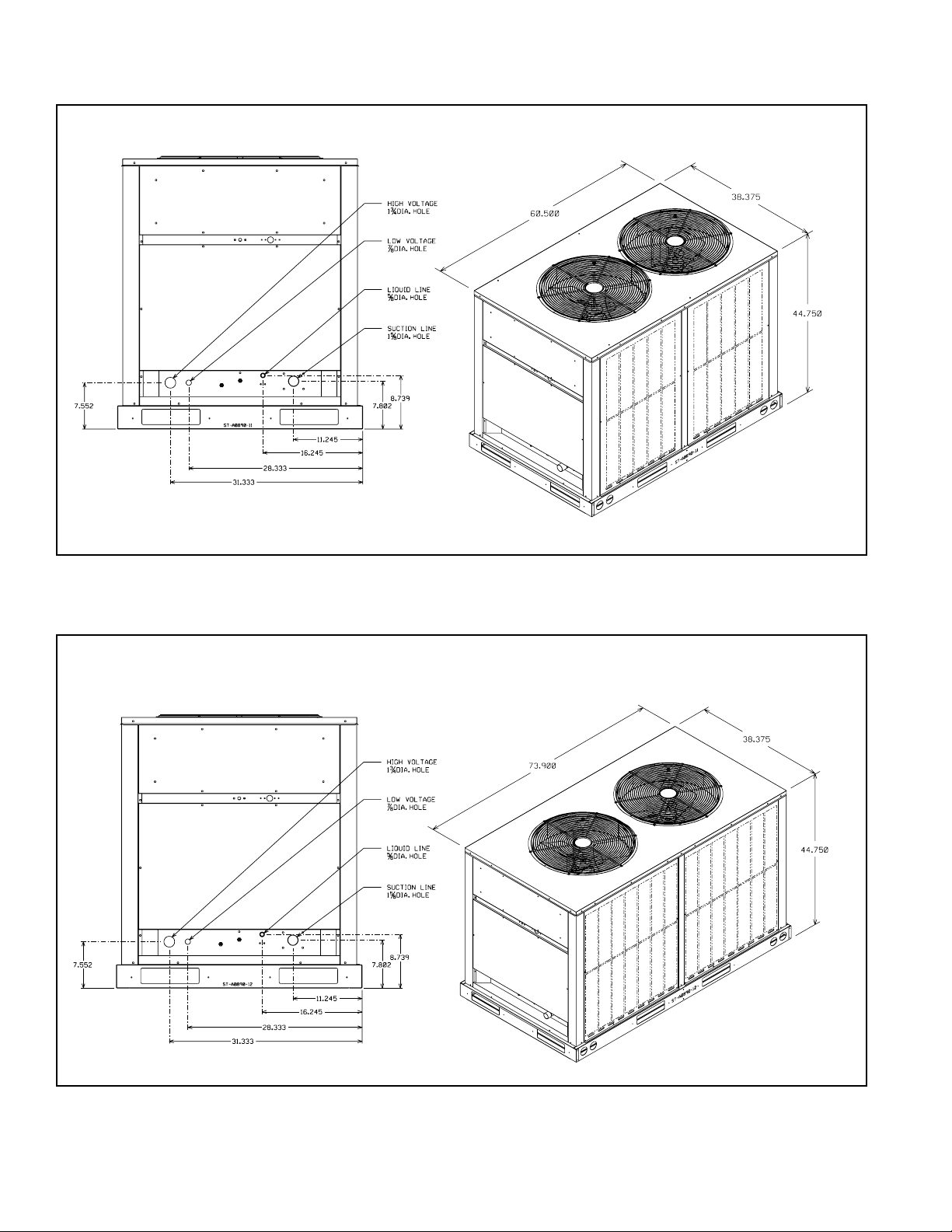
Figure 1: Dimensions – 10 Ton Units
ST-A0890-11
ST-A0890-12
ST-A0890-11
ST-A0890-12
ST-A0890-11
ST-A0890-11
Figure 2 : Dimensions – 12.5 Ton Units
4
IM 910
Page 5
Gauge (nominal)
Top (frame)
CONDENSER FANS:
Quantity
CONDENSER COIL:
Quantity
REFRIGERANT CONNECTION:
Vapor, O.D.F. (inches), Sweat Type (1 ea.)
CABINET:
Finish
Liquid O.D.F. (inches), Sweat Type (1ea.)
MODEL RCSNOMINAL CAPACITY (TONS)
Operating Weight (lbs.)
Shipping Weight (approximate, lbs.)
Type
RPM
CFM (total)
Diameter (inches)
Drive
Motor Horsepower (ea.)
Type
RPM
Rows
Fins per inch
Square Feet
Fins/Tubes
Tube Size, O.D. (inches)
Sheet Metal
Sides (posts)
Base rails (frame)
COMPRESSOR:
Quantity
10 12.5
569 640
609 680
11
Tandem Scroll Tandem Scroll
3500 3500
Capacity Steps
22
Percent from full load 50 50
23
6,800 6,800
24 24
Direct Direct
PSC PSC
1075
1075
22
22
18
22
27.0 32.875
Al/Cu Al/Cu
Powder Paint Powder Paint
Galvanized Galvanized
20 20
20 20
14 14
20
945
985
1
Tandem Scroll
3500
2
50
3
10,200
24
Direct
PSC
1075
2
3
18
40.375
Al/Cu
Powder Paint
Galvanized
20
20
14
15
818
858
1
Tandem Scroll
3500
2
50
3
10,200
24
Direct
PSC
1075
2
2
18
40.375
Al/Cu
Powder Paint
Galvanized
20
20
14
10E
12E
15E
20E
1/3 1/3
1/3
1/3
3/8 3/8
3/8
3/8
1-3/8
1-3/8
1-5/8
1-5/8
5/8
5/8
5/8
7/8
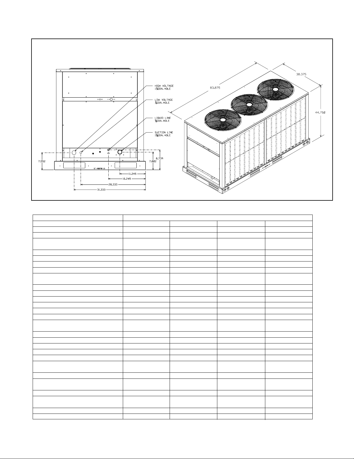
Figure 3 : Dimensions – 15 to 20 Ton Units
ST-A0890-11
ST-A0890-12
ST-A0890-11
S
T-A0890-12
ST-A0890-13
Table 1 – Physical Data
IM 910
5
Page 6

CONDENSING UNIT
Gauge (nominal)
Top (frame)
CONDENSER FANS:
Quantity
CONDENSER COIL:
Quantity
REFRIGERANT CONNECTION:
Vapor, O.D.F. (inches), Sweat Type (1 ea.)
CABINET:
Finish
Liquid O.D.F. (inches), Sweat Type (1ea.)
MODEL NO.
NOMINAL CAPACITY (TONS)
Operating Weight (lbs.)
Shipping Weight (approximate, lbs.)
T
ype
RPM
C
FM (total)
Diameter (inches)
Drive
Motor Horsepower (ea.)
Type
RPM
Rows
Fins per inch
Square Feet
Fins/Tubes
Tube Size, O.D. (inches)
Sheet Metal
Sides (posts)
Base rails (frame)
COMPRESSOR:
Quantity
10 12.5
569 640
609 680
11
T
andem Scroll Tandem Scroll
3500 3500
Capacity Steps
22
P
ercent from full load 50 50
23
6
,800 6,800
24 24
D
irect Direct
1
/3
1
/3
PSC PSC
1075
1075
2
2
22
18
22
27.0 32.875
Al/Cu Al/Cu
3
/8
3
/8
13/8 13/8
5
/8
5
/8
Powder Paint Powder Paint
Galvanized Galvanized
20 20
20 20
14 14
20
945
985
1
Tandem Scroll
3500
2
5
0
3
10,200
24
Direct
1
/3
PSC
1075
2
3
18
40.375
Al/Cu
3
/8
15/8
7
/8
Powder Paint
G
alvanized
20
20
14
15
818
858
1
T
andem Scroll
3500
2
5
0
3
10,200
24
Direct
1
/3
PSC
1075
2
2
18
40.375
Al/Cu
3
/8
15/8
5
/8
Powder Paint
Galvanized
2
0
20
14
A0890-14
Table 2: Electrical Data
lectrical
E
odel
M
umber
N
CS
R
0ECAZ 3-60-208/230 17.3/17.3 137 4.8 44/44 50/50 60/60 27 [2.51] 1 6600 [3115] 309 [8760] 569 [258.1] 609 [276.2]
1
10EDAZ 3-60-460 9 62 2.8 24 30 30 27 [2.51] 1 6600 [3115] 309 [8760] 569 [258.1] 609 [276.2]
10EYAZ 3-60-575 7.1 50 2 18 20 25 27 [2.51] 1 6600 [3115] 309 [8760] 569 [258.1] 609 [276.2]
12ECAZ 3-60-208/230 18.6/18.6 156 4.8 47/47 60/60 60/60 32.88 [3.05] 2 6600 [3115] 413 [11709] 640 [290.3] 680 [308.4]
2EDAZ 3-60-460 9 75 2.8 24 30 35 32.88 [3.05] 2 6600 [3115] 413 [11709] 640 [290.3] 680 [308.4]
1
2EYAZ 3-60-575 7.4 54 2 19 25 25 32.88 [3.05] 2 6600 [3115] 413 [11709] 640 [290.3] 680 [308.4]
1
5ECAZ 3-60-208/230 28.8/28.8 195 7.2 72/72 80/80 100/100 40.38 [3.75] 2 9900 [4672] 573 [16245] 819 [371.5] 859 [389.6]
1
5EDAZ 3-60-460 14.7 95 4.2 38 40 50 40.38 [3.75] 2 9900 [4672] 573 [16245] 819 [371.5] 859 [389.6]
1
15EYAZ 3-60-575 10.8 80 3 28 30 35 40.38 [3.75] 2 9900 [4672] 573 [16245] 819 [371.5] 859 [389.6]
20ECAZ 3-60-208/230 37.2/37.2 239 7.2 91/91 110/110 125/125 40.38 [3.75] 3 9900 [4672] 778 [22056] 945 [428.7] 985 [446.8]
20EDAZ 3-60-460 17.2 125 3.3 42 50 50 40.38 [3.75] 3 9900 [4672] 778 [22056] 945 [428.7] 985 [446.8]
20EYAZ 3-60-575 12.4 80 2.4 31 35 40 40.38 [3.75] 3 9900 [4672] 778 [22056] 945 [428.7] 985 [446.8]
Figure 4: Control Box Configuration
hase
P
requency (Hz)
F
oltage (Volts)
V
Compressor
Rated Load
Amperes
(RLA)
Locked Rotor
Amperes
(LRA)
Fan Motor
ull Load
F
A
mperes
FLA)
(
Minimum
ircuit
C
mpacity
A
mperes
A
Fuse or HACR
Circuit Breaker
inimum
M
A
M
mperes
A
aximum
mperes
ace Area
F
q. Ft. [m2]
S
Outdoor Coil
o.
N
ows
R
FM
C
L/s]
[
Refrig.
er
P
ircuit
C
z. [g]
O
N
bs. [kg]
L
Weight
et
hipping
S
bs. [kg]
L
Installation
Crankcase Heaters
These units are equipped with a crankcase heater that is facto-
The condensing unit consists of a completely assembled package which includes a compressor pack, condenser coils, fans,
fan motors, outdoor control box, factory wiring, factory tubing
and fittings.
ry wired to operate whenever the main power supply to the
unit is “on” and compressors are “off.” Before starting the
equipment after prolonged shut-down or at the time of initial
spring start-up, be sure that the circuits to the condensing units
are closed for at least 24 hours.
Order Parts
When reporting shortages or damaged parts, or when ordering
repair parts, give the complete unit model and serial numbers
which are stamped on the unit rating plate.
Standard Items
6 IM 910
Corrosive Environment
The metal parts of this unit may be subject to rust or deteriora-
tion if exposed to a corrosive environment. This oxidation
could shorten the equipment’s useful life. Corrosive elements
include salt spray, fog or mist in seacoast areas, sulphur or
chlorine from lawn watering systems, and various chemical
contaminants from industries such as paper mills and petrole-
um refineries.
If the unit is to be installed in an area where contaminants are
likely to be a problem, special attention should be given to the
equipment location and exposure.
Page 7

• Avoid having lawn sprinkler heads spray directly on the unit
INSTALLATION GENERAL
The condensing unit should be installed outdoors. It should be
located as near as possible to the evaporator section to keep
connecting refrigerant tubing lengths to a minimum. The unit must be
installed to allow a free air flow to the condenser coils.
If several units are installed adjacent to each other, care must be
taken to avoid recirculation of air from one condenser to another. In
all installations, adequate space must be provided for installation and
servicing.
cabinet.
• In coastal areas, locate the unit on the side of the building
away from the waterfront.
• Shielding provided by a fence or shrubs may give some protection, based on clearances recommended in this book.
Regular maintenance will reduce the build-up of contaminants
and help to protect the unit’s finish.
DANGER
!
▲▲
isconnect all power to unit before starting maintenance.
D
Failure to do so can cause electrical shock resulting in
severe personal injury or death.
• Frequent washing of the cabinet, fan blade and coil with
fresh water will remove most of the salt or other contaminants that build up on the unit.
• Regular cleaning and waxing of the cabinet with a good
automobile polish will provide some protection.
• A good liquid cleaner may be used several times a year to
remove matter that will not wash off with water.
Several different types of protective coatings are offered in
some areas. These coatings may provide some benefit, but the
effectiveness of such coating materials cannot be verified by
the equipment manufacturer.
Installation General
The condensing unit should be installed outdoors. It should be
located as near as possible to the evaporator section to keep
connecting refrigerant tubing lengths to a minimum. The unit
must be installed to allow a free air flow to the condenser
coils.
If several units are installed adjacent to each other, take care to
void recirculation of air from one condenser to another. In all
a
installations, adequate space must be provided for installation
and servicing.
The unit must not be connected to any duct work. Do not
locate unit under a roof drip; if necessary, install gutters, etc.,
to prevent water run-off onto the unit. To prevent air recircula-
ion, it is recommended that the unit not be installed under an
t
overhang. However, if this is necessary, allow a minimum of
60 inches above the unit for air discharge.
Rooftop Installation
If rooftop installation is required, make certain that the building construction is adequate for the weight of the unit. (Refer
to physical data chart.) Before placing the unit on the roof,
make certain that the nylon rigging slings are of sufficient
length to maintain equilibrium of the unit when lifting. Under
no circumstances should the unit be lifted by only one corner
for rooftop installation.
Slab Installation
Condensing units should be set on a solid level foundation.
When installed at ground level, the unit should be placed on a
6 inch cement slab. If the pad is formed at the installation site,
do not pour the pad tight against the structure, otherwise vibration will be transmitted from the unit through the pad.
Figure 5: Clearances
IM 910
7
Page 8
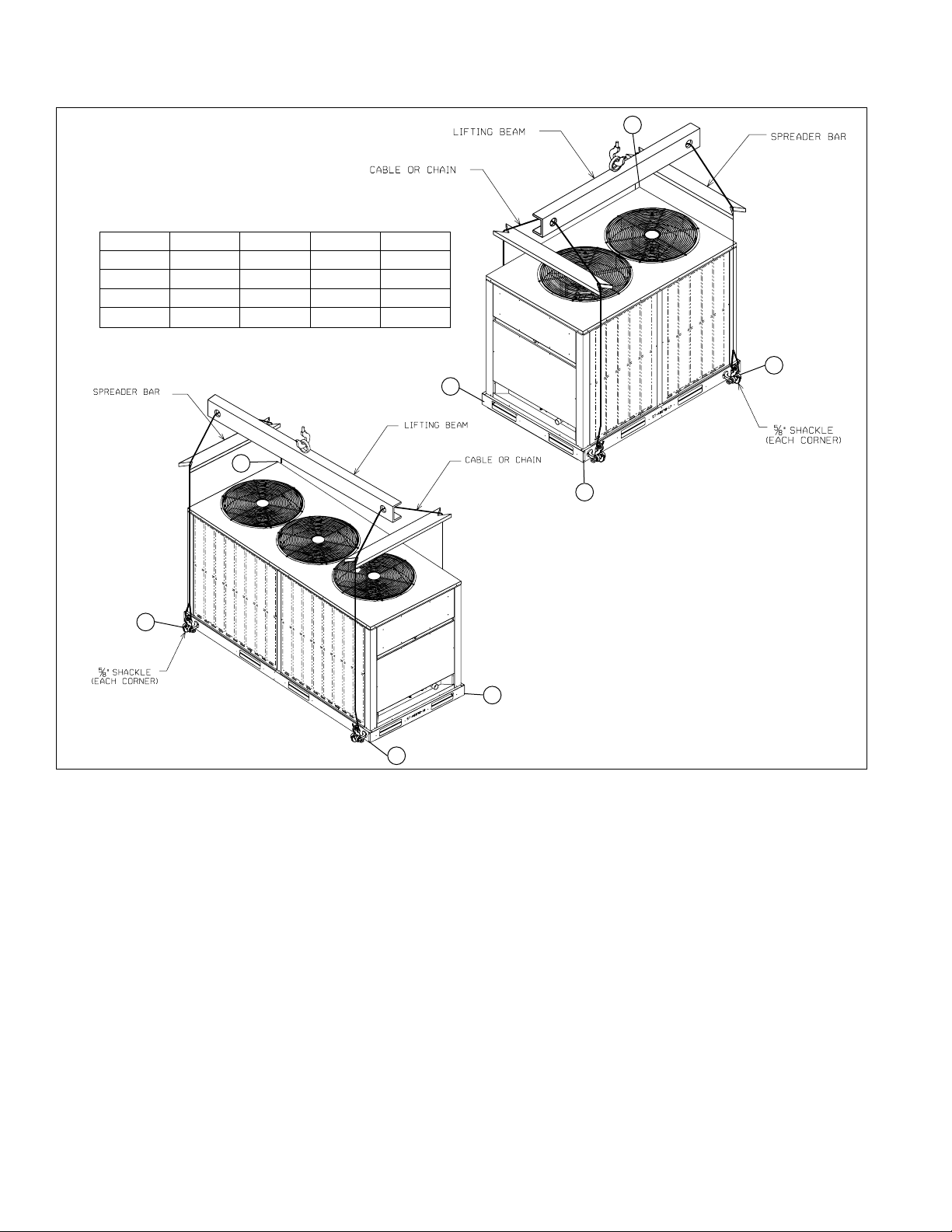
DETAIL
CORNER WEIGHTS (Pounds)
MODEL
10 TON 140 150 135 144
12.5 TON 167 163 140 170
15 TON 211 198 211 198
20 TON 238 246 235 227
ABCD
15 & 20
TON
10 & 12.5
TON
ST-A0890-17
ST-A0890-18
Figure 6: Rigging
B
D
A
B
C
A
D
C
8 IM 910
Page 9
Installation of Piping
INSTALLATION OF PIPING
IMPORTANT: CONDENSING UNITS ARE SHIPPED WITH A NITROGEN
HOLDING CHARGE. EVACUATE CONDENSING UNIT BEFORE CHARGING
WITH REFRIGERANT.
Once located, the condensing unit is ready to be interconnected with
the evaporator using ONLY refrigeration grade dehydrated tubing.
T
he following should be considered when connecting the tubing.
1. Pitch the vapor line toward the compressor approximately 1/2 inch
every 10 feet to facilitate oil return.
2. It is recommended that the sight glass, filter drier and liquid line
solenoid valve be installed in the liquid line just prior to the
evaporator.
3. Silver solder (such as silfos, Easy Flow, etc.) should be used for all
refrigerant joints.
4. Thoroughly clean all joints before fluxing. DO NOT USE ACID
FLUX.
5. When fluxing, limit the application of paste to the minimum and
always apply flux to the male portion of the connection.
6. vapor lines should be insulated to prevent condensate drip. Use
insulation of at least 3/8 inch wall thickness. The insulation should
be installed on the tubing prior to making the sweat connections.
7. Insulate the liquid line whenever the heat pick-up or transfer can
affect the sub-cooling.
8. Care should be taken to avoid transmission of noise or vibration to
building structure.
!
WARNING
DO NOT USE OXYGEN TO PURGE LINES OR PRESSURE
SYSTEM FOR LEAK TEST. OXYGEN REACTS VIOLENTLY
WITH OIL, WHICH CAN CAUSE AN EXPLOSION RESULTING
I
N SEVERE PERSONAL INJURY OR DEATH.
TABLE 2
REFRIGERANT PIPING DATA
21/8
15/8
13/8
11/8
7
/8
3
/4
TUBE SIZE
(IN.) O.D.
5
/8
1
/2
SOLE-
NOID
VALVE
ANGLE
VALVE
SHORT
RADIUS
ELL
LONG
RADIUS
ELL
TEE LINE
FLOW
TEE
BRANCH
FLOW
70
72
75
78
87
102
115
141
24
25
25
28
29
33
34
39
4.7
5.7
6.5
7.8
2.7
3.2
3.8
5.2
3.2
3.9
4.5
5.3
1.9
2.2
2.6
3.4
1.7
2.3
2.9
3.7
5.2
6.9
8.7
12.0
6.6
8.2
9.7
12.0
8.0
10.0
12.0
16.0
FOR NON-FERROUS VALVES & FITTINGS (BRAZED)
EQUIVALENT LENGTH (FT.) [m] OF STRAIGHT TYPE "L" TUBING
a
pproximately 3 PSIG pressure drop.
approximately 3 PSIG pressure drop.
adjacent to evaporator. Filter drier should be between the
condensing unit and sight glass.
. Pitch all horizontal vapor lines downward in the direction of flow
prevent dirt and moisture from entering the piping.
possible to minimize piping runs.
tubing noise transmission into the conditioned space, the suction
clamp must be installed after tubing is brazed as illustrated in
figure 7.
92-22205-38
. Size liquid line for no more than 10
o
F
loss which corresponds to
o
(
1/2" to 10 ft. run).
TYPICAL PIPING RECOMMENDATIONS
The following will be of help in accomplishing a successful
i
nstallation.
approximately 3 PSIG pressure drop.
2. Size vapor lines for no more than 2F loss which corresponds to
approximately 3 PSIG pressure drop.
3. Install sight glass, filter drier and solenoid valve in liquid line
adjacent to evaporator. Filter drier should be between the
condensing unit and sight glass.
4. Pitch all horizontal vapor lines downward in the direction of flow
5. When making up refrigerant piping, take every precaution to
prevent dirt and moisture from entering the piping.
6. Locate the condensing unit and evaporator(s) as close together as
possible to minimize piping runs.
7. Liquid or vapor lifts not to exceed 60 ft.
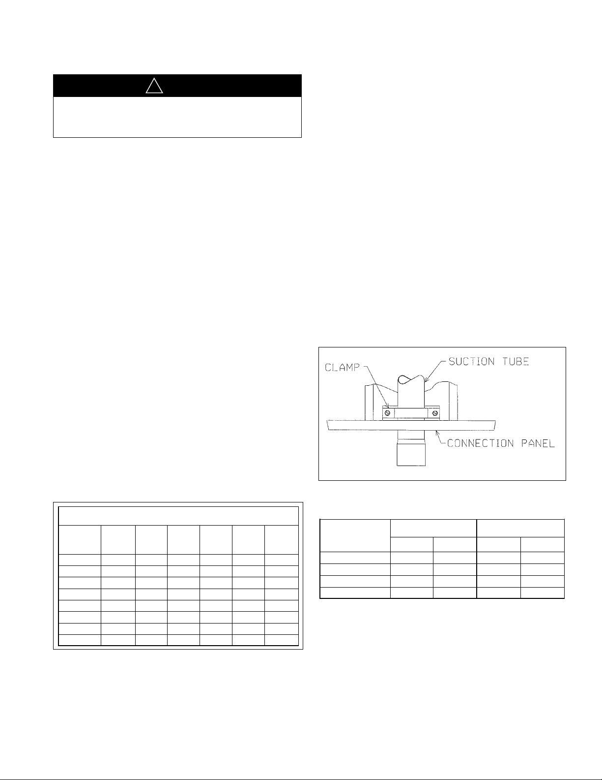
8. To prevent suction line breakage due to vibration and to prevent
tubing noise transmission into the conditioned space, the suction
clamp must be installed after tubing is brazed as illustrated in
figure 7.
92-22205-38
RECOMMENDED VAPOR AND LIQUID LINE
SIZES FOR VARIOUS LENGTHS OF RUN
200
EQUIVALENT
LENGTH TO
EVAPORATOR
(FEET)
200
LIQUID LINE O.D.
SIZES (INCHES)
VAPOR LINE O.D.
SIZES (INCHES)
150
150
1
5
/8
15/8
15/8
21/8 21/8
21/8
15/8
15/8
7
/8
7
/8
7
/8
7
/8
3
/4
3
/4
5
/8
5
/8
NOTE: Line length between condenser and evaporator (suction and liquid) not
to exceed 150’ equivalent length.
1. Size liquid line for no more than 10oF loss which corresponds to
o
(1/2" to 10 ft. run).
0” to 15”
16” to 50”
51” to 100”
101” to 150”
WARNING
!
▲▲
Do not use oxygen to purge lines or pressure system for
leak test. Oxygen reacts violently with oil, which can cause
n explosion resulting in severe personal injury or death.
a
NOTE – The condensing unit is shipped with a holding charge of
dry nitrogen which must be purged from the unit before evacuation.
Once located, the condensing unit is ready to be interconnected with the evaporator using ONLY refrigeration grade dehydrated tubing.The following should be considered when connecting the tubing.
1 Pitch the vapor line toward the compressor approximately
1/2 inch every 10 feet to facilitate oil return.
2 It is recommended that the sight glass, filter drier and liq-
uid line solenoid valve be installed in the liquid line just
prior to the evaporator.
3 Silver solder (such as silfos, Easy Flow, etc.) should be
used for all refrigerant joints.
4 Thoroughly clean all joints before fluxing. DO NOT USE
ACID FLUX.
5 When fluxing, limit the application of paste to the mini-
mum and always apply flux to the male portion of the
connection.
6 Vapor lines should be insulated to prevent condensate
drip. Use insulation of at least 3/8 inch wall thickness.
The insulation should be installed on the tubing prior to
making the sweat connections.
7 Insulate the liquid line whenever the heat pick-up or
transfer can affect the sub-cooling.
8 Care should be taken to avoid transmission of noise or
vibration to building structure.
Table 3: Refrigerant Piping Data
Typical Piping Recommendations
The following will be of help in accomplishing a successful
installation.
1 Size liquid line for no more than 10°F loss which corre-
sponds to approximately 3 psig pressure drop.
2 Size vapor lines for no more than 2°F loss which corre-
sponds to approximately 3 psig pressure drop.
3 Install sight glass, filter drier and solenoid valve in liquid
line adjacent to evaporator. Filter drier should be between
the condensing unit and sight glass.
4 Pitch all horizontal vapor lines downward in the direction
of flow (1/2” to 10 ft. run).
5 When making up refrigerant piping, take every precaution
to prevent dirt and moisture from entering the piping.
6 Locate the condensing unit and evaporator(s) as close
together as possible to minimize piping runs.
7 Liquid or vapor lifts not to exceed 60 ft.
8 To prevent suction line breakage due to vibration and to
prevent tubing noise transmission into the conditioned
space, the suction clamp must be installed after tubing is
brazed as illustrated in figure 7.
Figure 7: Suction Clamp
Table 4: Recommended Vapor and Liquid Line Sizes for
Various Lengths of Run
IM 910
9
Page 10

NOTES:
1.When evaporator coil is above condenser, the pressure drop due to vertical lift (.5 PSIG per foot of lift) must
be added to the pressure drop derived from this curve.
3.Do not oversize liquid line. Oversized liquid lines add significantly to the amount of refrigerant required to
charge the system.
4.The maximum recommended velocity with solenoid valves or other quick closing devices in the liquid line is
300 FPM.
SYSTEM CAPACITY T0NS
7
/
8
"
O
.
D.
3
/
4
"
O
.
D.
5
/
8
"
O
.
D.
1
/
2
"
O
.
D.
3
/
8
"
O
.
D.
5
/
1
6
"
O
.
D.
1
/
4
"
O
.
D.
1
5
0
F
P
M
2
0
0
F
P
M
3
0
0
F
P
M
PRESSURE DROP PSIG
2.Size liquid line for no more than 10
o
F loss (approximately 30 PSIG total pressure drop).
SYSTEM CAPACITY T0NS
7
/
8
"
O
.
D
.
3
/
4
"
O
.
D
.
5
/
8
"
O
.
D
.
1
/
2
"
O
.
D
.
3
/
8
"
O
.
D
.
5
/
1
6
"
O
.
D.
1
/
4
"
O
.
D.
15
0
F
P
M
20
0
F
P
M
3
0
0
F
P
M
PRESSU
RE D
ROP
PSIG
Figure 8: Liquid Line Pressure Drop Per 100 Feet Equivalent Length
NOTES:
1.When evaporator coil is above condenser, the pressure drop due to vertical lift (.5 PSIG per foot of lift) must
be added to the pressure drop derived from this curve.
3.Do not oversize liquid line. Oversized liquid lines add significantly to the amount of refrigerant required to
charge the system.
4.The maximum recommended velocity with solenoid valves or other quick closing devices in the liquid line is
300 FPM.
SYSTEM CAPACITY T0NS
7
/
8
"
O
.
D.
3
/
4
"
O
.
D.
5
/
8
"
O
.
D.
1
/
2
"
O
.
D.
3
/
8
"
O
.
D.
5
/
1
6
"
O
.
D.
1
/
4
"
O
.
D.
1
5
0
F
P
M
2
0
0
F
P
M
3
0
0
F
P
M
PRESSURE DROP PSIG
SYSTEM CAPACITY T0NS
2
1
/
8
"
O
.
D
.
1
5
/
8
" O.D
.
1
3
/
8
" O.D
.
1
1
/
8
" O.D
.
7
/
8
" O.D
.
3
/
4
" O.D
.
5
/
8
" O.D
.
4
0
0
0
F
P
M
M
A
X
I
M
UM
1
5
0
0
F
P
M
M
I
N
I
M
U
M
(
H
E
A
T
P
U
M
P
S
)
7
0
0
F
P
M
M
I
N
I
M
U
M
NOTES:
1.The minimum velocity line (700 fpm) is recommended for cooling only units with vertical or horizontal run refrigerant lines.
2.For suction pressure drop (PSIG), multiply percent (%) loss by 1.18.
2.Size liquid line for no more than 10
o
F loss (approximately 30 PSIG total pressure drop).
(Type L Copper Tubing)
Figure 9: Suction Line System Capacity Loss In Percent Per 100 Feet Equivalent Length
(Type L Copper Tubing)
10
IM 910
Page 11

AIR
F
LOW
H
ORIZONTAL P TRAP
VERTICAL
Figure 10: Typical Drain Piping
NOTE: PIPING ACCESSORIES SHOWN SHOULD BE MOUNTED AS CLOSE TO AIR
HANDLER AS POSSIBLE.
AIR
FLOW
HORIZONTAL P TRAP
VERTICAL
!
WARNING
SOLID COPPER WIRE - AWG
3.0 16 14 12 10 10 10
2.5 16 14 12 12 10 10
2.0 18 16 14 12 12 10
50 100 150 200 250 300
Length of Run - Feet (1)
Thermostat
Load - Amps
(1) Wire length equals twice the run distance.
Figure 11: Coil Above Condensing Unit
Electrical Wiring
NNOOTTEE ——
Code (CEC in Canada) and any local ordinance that may apply.
Electrical Power
It is important that proper electrical power is available at the
unit. Voltage must not vary more than 10% from that stamped
n the rating plate. (See Electrical Data Table on Page 6 for
o
minimum and maximum voltage.) Interphase voltage variation
on three-phase units must not be more than 3%. Contact local
power company for correction of improper voltage or phase
unbalance.
IMPORTANT: Models equipped with scroll compressors must be
phased correctly for proper compressor rotation. If the compressor is noisy or if suction and discharge pressures do not appear
normal, reverse any two power leads to the unit. Extended run
time in reverse rotation will damage the compressor and lead to
premature failure.
Power Wiring
Power wiring should be run in grounded rain-tight conduit.
See Electrical Data Table for wire ampacity and proper wire
size.
Field wiring must comply with the National Electric
Figure 12: Coil Below Condensing Unit
Wire Routing
POWER WIRING MUST BE RUN IN CONDUIT. Conduit
must be run through the connector panel below the service
cover and attached to the bottom of the control box.
If low (extra-low in Canada) voltage control wire is run in
conduit with power supply, Class I insulation is required. If
run separate, Class II is required. Low voltage wiring may be
run through the insulated bushing provided in the 7/8” hole in
the connector panel, then route to the control box.
WARNING
!
▲▲
After completing wiring, check all electrical connections,
including factory wiring within the unit. Make sure all connections are tight. Replace and secure all electrical box covers and access doors before leaving the unit or turning on
power to the unit. Failure to do so can cause a fire or electrical shock resulting in property damage, personal injury or
death.
Table 5: Field Wire Size for 24 Volt Thermostat
IM 910
11
Page 12

WARNING
!
▲▲
This unit must be permanently grounded. A ground lug is
rovided near the contactor for a ground wire. Failure to do
p
so can cause a fire or electrical shock resulting in property
damage, severe personal injury or death.
Grounding
A grounding lug is provided in control box for a ground wire.
Grounding also may be accomplished by grounding the power
line conduit to the unit.
Thermostat
two-stage cooling, two-stage heating (if heating is used)
A
thermostat should be mounted on an inside wall about five feet
above the floor in a location where it will not be affected by
the sun or drafts from open doors or other sources. Install,
level, and after installation check the thermostat calibration
nd recalibrate if necessary.
a
12 IM 910
Page 13

service valve. The actual line temperature should be 15 to 25F
higher than the saturation temperature corresponding to the
vapor pressure. If superheat is measured at evaporator, the
saturation temperature corresponding to the vapor pressure.
gauges.
be replaced to prevent leaks.
LIQUID
TUBE
TUBE SIZE
O.D. (INCHES)
SUCTION
TUBE
5
/8 1.86
7
/8 2.67 .06
11/8 .15
13/8 .22
15/8 .29
21/8 .43
o
to 20o higher than the
o
actual line temperature should be 15
o
CIRCUIT
AMPACITY
COPPER
WIRE GAUGE*
DISTANCE IN FEET
1
00 150 200 250 300
40 6 4 3 2 1
4
5 4 3 2 1 1/0
50 4 3 2 1 1/0
60 4 2 1 1/0 2/0
70 3 2 1/0 2/0 3/0
8
0 3 1 1/0 2/0 3/0
90 2 1/0 2/0 3/0 4/0
100 2 1/0 2/0 3/0 4/0
110 1 2/0 3/0 4/0 250
125 1 2/0 3/0 4/0 250
Table 6: Copper Wire Size (1% Voltage Drop)
LEAK TESTING
Pressurize line set and coil through service fittings with dry nitrogen
to 150 PSIG maximum. Leak test all joints using liquid detergent. If a
leak is found, recover pressure and repair.
EVACUATION AND CHARGING
The evacuation of any system component that has been exposed to
atmosphere or lost its charge is essential before charging. Never
attempt to operate a system while it is under a vacuum.
NOTE: The condensing unit is shipped with a holding charge of dry
nitrogen which must be purged from the unit before evacuation.
1. Since the condensing unit itself must be evacuated, open the
vapor, discharge and liquid shut-off valves.
2. Use a refrigeration type vacuum pump capable of evacuation in
the 500 micron range.
3. Connect the vacuum pump to the service manifold assembly with
!
WARNING
DO NOT USE OXYGEN TO PURGE LINES OR PRESSURE
SYSTEM FOR LEAK TEST. OXYGEN REACTS VIOLENTLY
WITH OIL, WHICH CAN CAUSE AN EXPLOSION RESULTING
IN SEVERE PERSONAL INJURY OR DEATH.
10 Ton
309 oz.
12.5 Ton
413 oz.
*System with 0 Feet of Tubing
15 Ton
573 oz.
20 Ton
778 oz.
COPPER WIRE
GAUGE (75°C INSULATION)
Leak Testing
Pressurize line set and coil through service fittings with dry
nitrogen to 150 psig maximum. Leak test all joints using liquid
detergent. If a leak is found, recover pressure and repair.
WARNING
!
▲▲
Do not use oxygen to purge lines or pressure system for
leak test. Oxygen reacts violently with oil, which can cause
an explosion resulting in severe personal injury or death.
Evacuation and Charging
The evacuation of any system component that has been
exposed to atmosphere or lost its charge is essential before
charging. Never attempt to operate a system while it is under a
vacuum.
NOTE – The condensing unit is shipped with a holding charge of
dry nitrogen which must be purged from the unit before evacuation.
1 Since the condensing unit itself must be evacuated, open
the vapor, discharge and liquid shut-off valves.
2 Use a refrigeration type vacuum pump capable of evacua-
tion in the 500 micron range.
3 Connect the vacuum pump to the service manifold assem-
bly with a pressure gauge that will read 30 inches vacuum. Connect the service manifold to the vapor line service port. (“Low” shown on label.)
4 With an accurate scale, 1/2 oz., set refrigerant tank up so
its weight can be measured while in a position to charge
liquid. (Unit must be off.) Energize liquid line solenoid
valve by wiring valve to 24V power supply (or open by
manual stem if applicable).
5 Connect to the liquid line service port. (“High” shown on
label.) Shut off tank and evacuate the system. The pressure gauge should read at least 29.5” of vacuum.
6 Triple evacuate the system.
7 The refrigerant system will now be free of noncondens-
ables.
8 Remove vacuum pump from 3-way valve.
IM 910
9 Install refrigerant tank (liquid charging) to liquid line ser-
vice valve.
10 Before tightening, purge tank and service valve hose.
11 Note weight of refrigerant tank.
12 De-energize liquid line solenoid valve. Open refrigerant
tank valve. Allow pressure in tank and unit to equalize.
13 Close off service valve to liquid line service port and note
weight of refrigerant tank.
14 Position tank for gas charging.
15 Re-wire liquid line solenoid to thermostat control. Close
main disconnect switch and turn thermostat to lowest setting.
16 Charge unit per Tables 7 and 8.
17 Adjust refrigerant charge to obtain pressures indicated in
the temperature/pressure charging charts beginning on
page 17.
18 Note weight of refrigerant tank.
19 When system has stabilized, check superheat at the suc-
tion line service valve. The actual line temperature should
be 15° to 25°F higher than the saturation temperature corresponding to the vapor pressure. If superheat is measured
at evaporator, the actual line temperature should be 15 to
20° higher than the saturation temperature corresponding
to the vapor pressure.
20 Close service ports on vapor and liquid valves. Remove
service gauges.
21 Replace service port caps and valve stem caps. These
caps must be replaced to prevent leaks.
22 Record total charge quantity on rating plate.
Table 7: Basic System Charge*
Table 8: Required Ounces of R-22 Charge Per Foot of
Tubing
13
Page 14

Final Leak Testing
PRE-START CHECK
1. Is condensing unit properly located and level?
2. Is air free to travel to and from condensing unit?
3. Is the wiring correct and according to the unit wiring diagram?
4. Are wiring connections tight? (Including those in unit and
compressor electrical box.)
5. Is the unit properly grounded?
6. Is circulating air blower correctly wired?
7. Is condensing unit properly fused?
8. Is the thermostat level, correctly wired and in a good
location?
9. Is the ductwork correctly sized, run, taped and insulated?
10. Is refrigerant tubing neatly run and vapor line thoroughly
insulated?
11. Is condensate drain line properly sized, run, trapped and
pitched?
12. Are refrigerant connections tight and leak tested?
13. Is filter clean and in place?
14. Does the condenser fan turn free without rubbing?
15. Is the fan tight on the fan shaft?
16. Are all covers and access panels in place to prevent air loss?
G YES G NO
G YES G NO
G YES G NO
G YES G NO
G YES G NO
G YES G NO
G YES G NO
G YES G NO
G YES G NO
G YES G NO
G YES G NO
G YES G NO
G YES G NO
G YES G NO
G YES G NO
G YES G NO
After the unit has been properly evacuated and charged, a
alogen leak detector should be used to detect leaks in the sys-
h
tem. All piping within the condensing unit, evaporator, and
Table 9: Charging Hints
SYMPTOM POSSIBLE CAUSE REMEDY
High head pressure a. Air flow to or from condenser a. Remove obstruction, relocate
restricted or dirty condenser condensing unit—if necessary clean
. Faulty condenser fan or motor. b. Replace.
b
c. Overcharge of refrigerant c. Reduce charge.
d. Air in system. d. Evacuate and recharge.
Low head pressure a. Short of refrigerant. a. Check for leak, add charge.
b. Low evaporator air flow. b. Increase blower speed, check
Low vapor & a. Short of refrigerant. a. Check for leak—add refrigerant.
hot compressor
Excessive sweating a. Low indoor airflow a. Increase speed of air handler blower
b. Excess refrigerant b. Slowly reduce charge.
interconnecting tubing should be checked for leaks. If a leak is
etected, the refrigerant should be recovered before repairing
d
the leak. The Clean Air Act prohibits releasing refrigerant into
the atmosphere.
condenser.
filters.
or reduce restriction—replace air
filter.
Pre-Start Check
14
IM 910
Page 15

Accessories Installation
ACCESSORIES
SERVICE VALVE
INSTALLATION (Refer to Figure 19)
1
. Remove clamp securing suction line ext. tube (if applicable).
3
. Remove suction line Ext. tube by sweating at reducer/suction line
line). Remove excess braze material from surface.
a
t this time).
7. Braze valve.
LOUVERS
INSTALLATION (Refer to Figure 20)
1. Remove two screws from top panel where louver will install.
2. Slide top of louver panel under lip of the top panel and slide into
place.
3. Attach with four screws provided.
ST-A0890-15
2
. Remove connector panel “A”.
4. Slide service valve “C” onto reducer/suction line “B” (do NOT braze
5. Install connector panel “A”.
6. Install bracket “D”.
“B” (reducer required on some models and remains on suction
ST-A0890-15
Service Valve (See Figure 14)
1 Remove clamp securing suction line ext. tube (if applica-
ble).
2 Remove connector panel “A”.
3 Remove suction line Ext. tube by sweating at reduc-
er/suction line“B” (reducer required on some models and
remains on suction line). Remove excess braze material
from surface.
4 Slide service valve “C” onto reducer/suction line “B” (do
NNOOTT
braze at this time).
5 Install connector panel “A”.
6 Install bracket “D”.
7 Braze valve.
Louvers (See Figure 13)
1 Remove two screws from top panel where louver will
install.
2 Slide top of louver panel under lip of the top panel and
slide into place.
3 Attach with four screws provided.
Figure 13: Optional Louver Installation
Figure 14: Optional Service Valve Installation
IM 910
15
Page 16

Maintenance and Operation
• All access panels must be in place when unit is in opera-
tion.
• For maximum efficiency, the condenser coil must be kept
clean. Periodic inspections, depending on local conditions
are recommended. If it is necessary to clean the condenser coil, use a common garden hose.
• Never operate the unit without filters installed in the air
handler.
Crankcase Heaters
All units are equipped with crankcase heaters that are factory
wired to operate whenever the main power supply to the unit
is “on” and compressors are “off.” Before starting the equipment after prolonged shutdown or at the time of initial startup, be sure that the circuits to the condensing units are closed
for at least 24 hours.
Low Pressure Switch (LPC)
Acts as safety against loss of refrigerant.
Relay (R)
nergizes the compressor contactor when safety circuit is
E
made.
Replacement Parts
To find your local McQuay Certified Parts Distributor, go to
www.mcquay.com and select Parts Locator.
Charge Information
Refer to the appropriate charge chart beginning on page 17.
Wiring Diagrams
Refer to the appropriate wiring diagram beginning on page 22.
Contactor
The contactor is an electrical switch which operates the compressor and condenser fans. Relay activates contactor when
safety circuit is made.
High Pressure Switch (HPC)
Opens the contactor circuit on high refrigerant pressure —
Manual Reset — check for cause of tripping before putting
unit back in service.
WARNING
!
▲▲
Do not wire around the high pressure switch. 15 ton unit
compressors are not provided with internal pressure relief
means. Failure to follow this warning can cause an explosion resulting in personal injury or death.
Troubleshooting
Refer to the troubleshooting chart beginning on page 23.
16
IM 910
Page 17

Figure 15: Charging Chart – 10 Ton Units
IM 910
17
Page 18

Figure 16: Charging Chart – 12.5 Ton Units
18
IM 910
Page 19
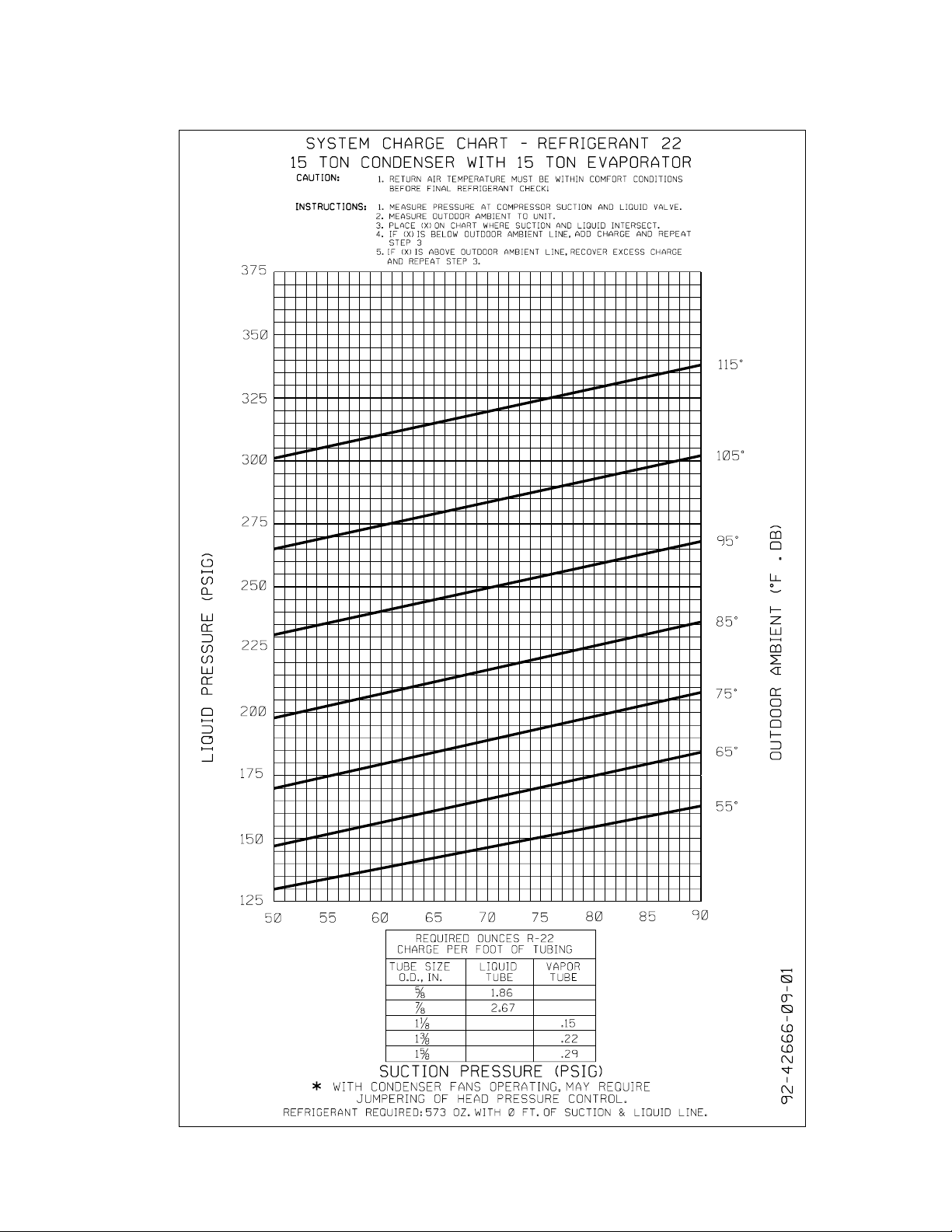
Figure 17: Charging Chart – 15 Ton Units
IM 910
19
Page 20

Figure 18: Charging Chart – 20 Ton Units
20 IM 910
Page 21

Figure 19: Charging Chart – 15 Ton Units
IM 910
21
Page 22

Figure 20: Wiring Diagram 10-20 Ton Units
22
IM 910
Page 23
Trouble Shooting Chart
DANGER
!
▲▲
Disconnect all power to unit before servicing. Contactor may break only one side. Failure to shut off power can cause electrical
shock resulting in personal injury or death.
SYMPTOM POSSIBLE CAUSE REMEDY
Unit will not run • Power off or loose electrical connection • Check for correct voltage at compressor contactor in
• Thermostat out of calibration-set too high • Reset
• Defective contactor • Check for 24 volts at contactor coil - replace if contacts
• Blown fuses • Replace fuses
• Transformer defective • Check wiring-replace transformer
• High pressure control open (if provided) • Reset-also see high head pressure remedy-The high
• Interconnecting low voltage wiring damaged • Replace thermostat wiring
Condenser fan runs, • Run capacitor defective (single phase only) • Replace
compressor doesn’t • Start relay defective (single phase only) • Replace
• Loose connection • Check for correct voltage at compressor -
• Compressor stuck, grounded or open motor • Wait at least 2 hours for overload to reset.
winding, open internal overload. If still open, replace the compressor.
• Low voltage condition • At compressor terminals, voltage must be within 10%
• Low voltage condition • Add start kit components
Insufficient cooling • Improperly sized unit • Recalculate load
• Improper airflow • Check - should be approximately 400 CFM per ton.
• Incorrect refrigerant charge • Charge per procedure attached to unit service panel
• Air, non-condensibles or moisture in system • Recover refrigerant, evacuate & recharge, add filter drier
• Incorrect voltage • At compressor terminals, voltage must be within 10%
Compressor short cycles • Incorrect voltage • At compressor terminals, voltage must be ±10% of
• Defective overload protector • Replace - check for correct voltage
• Refrigerant undercharge • Add refrigerant
Registers sweat • Low evaporator airflow • Increase speed of blower or reduce restriction - replace
High head-low vapor • Restriction in liquid line, expansion device • Remove or replace defective component
pressures or filter drier
• Flow check piston size too small • Change to correct size piston
• Incorrect capillary tubes • Change coil assembly
• TXV does not open • Replace TXV
High head-high or • Dirty condenser coil • Clean coil
normal vapor pressure - • Refrigerant overcharge • Correct system charge
Cooling mode • Condenser fan not running • Repair or replace
• Air or non-condensibles in system • Recover refrigerant, evacuate & recharge
Low head-high vapor • Flow check piston size too large • Change to correct size piston
pressures • Defective Compressor valves • Replace compressor
• Incorrect capillary tubes • Replace coil assembly
Low vapor - cool • Low evaporator airflow • Increase speed of blower or reduce restriction - replace
evaporator coil • Operating below 65°F outdoors • Add Low Ambient Kit
• Moisture in system • Recover refrigerant - evacuate & recharge - add filter
• TXV limiting refrigerant flow • Replace TXV
High vapor pressure • Excessive load • Recheck load calculation
• Defective compressor • Replace
Fluctuating head & vapor • TXV hunting • Check TXV bulb clamp - check air distribution on coil -
• Air or non-condensate in system • Recover refrigerant, evacuate & recharge
Gurgle or pulsing noise • Air or non-condensibles in system • Recover refrigerant, evacuate & recharge
at expansion device or
liquid line
control box
are open
pressure control opens at 450 psig
check & tighten all connections
of rating plate volts when unit is operating
of rating plate volts when unit is operating.
nameplate marking when unit is operating.
air filter
air filter
drier
replace TXV
IM 910
23
Page 24

Service and Warranty Procedure
S
ervice and Warranty Procedure
Replacement Parts
When contacting McQuay for service or replacement parts,
provide the model number, serial number, and unit part
number of the unit as stamped on the serial plate attached to
the unit. For questions regarding wiring diagrams, provide the
number on the specific diagram. If replacement parts are
required, include the date of unit installation, the date of
failure, an explanation of the malfunction, and a description of
the replacement parts required.
Scroll Compressor
All McQuay Rooftop products include a first-year parts only
warranty. The warranty period extends 12 months from startup
or 18 months from date of shipment, whichever comes first.
Labor to install these parts is not included with this warranty.
Compressors are considered a part and are included in this
standard warranty.
All Compressors
Replacement compressors for McQuay Rooftop Units can be
obtained from the McQuay Service Parts department.
The decision to replace the failed portion of the compressor
tandem, as opposed to replacing the entire tandem, must be
decided based on the following.
1 In warranty: Warranty only covers replacement of the failed
portion of the tandem.
2 Out of warranty: The customer decides whether to replace
the entire tandem or just a portion.
3 Some equipment may include the extended 2nd - 5th year
compressor warranty option.
Order the replacement compressor through the McQuay Parts
Department (Minneapolis).
1 Contact the McQuay Parts Department for compressor
availability.
2 Send a completed parts order form to the McQuay Parts
Department.
3 The Parts Department processes the order and the
c
ompressors are shipped from our Dayton, OH warehouse
v
ia ground transportation. If next-day air is required,
i
ndicate this on the parts order form and a freight charge
will be billed to your account. Air freight costs are not
covered under the McQuay warranty.
4 After the failed compressor is replaced, return it to McQuay
International with a Return Goods Tag attached, which you
will receive in the mail. It must be attached to the
compressor. The Return Goods Tag has instructions on
where to send the compressor. If the compressor is not
returned, you will be billed for the replacement compressor.
5 Consideration may be given at this time to a compressor
teardown analysis, depending on the history of failures.
In-Warranty Return Material Procedure
Material other than compressors may not be returned except by
permission of authorized factory service personnel of McQuay
International at Minneapolis, Minnesota.
A “return goods” tag will be sent to be included with the
returned material. Enter the information as called for on the tag
in order to expedite handling at out factories and issuance of
credits. All parts shall be returned to the factory designated on
the return goods tag, transportation charges prepaid.
The return of the part does not constitute an order for
replacement. A purchase order for the replacement part must
be entered through your nearest McQuay representative. The
order should include the component's part number and
description and the model and serial numbers of the unit
involved.
If it is determined that the failure of the returned part is due to
faulty material or workmanship within the standard warranty
period, credit will be issued on the customer's purchase order.
24 IM 910
Page 25

RCS Condensing Unit Equipment Warranty Registration Form
To comply with the terms of McQuay Warranty, complete and return this Equipment
Warranty Registration Form within 10 days to McQuay, Warranty Department
C
heck, test, and start procedure for RoofPak roof mounted air conditioners
with or without heat recovery and roof mounted air handlers.
J
ob Name: __________________________________________________________ McQuay G.O. No.: ________________
Installation address: __________________________________________________________________________________
City: _______________________________________________________________________________ State: _________
P
urchasing contractor: ________________________________________________________________________________
C
ity:________________________________________________________________________________ State: _________
N
ame of person doing start-up (print)____________________________________________________________________
Company name ____________________________________________________________________
Address __________________________________________________________________________
C
ity/State/Zip ______________________________________________________________________
Unit model number:___________________________________________________ Unit serial number: ______________
Compressor #1 model number: ________________________________________ Serial number: __________________
Compressor #2 model number: ________________________________________ Serial number: __________________
Circle Yes or No. If not applicable to the type of unit, circle N/A.
I. INITIAL CHECK
A. Is any shipping damage visible? . . . . . . . . . . . . . . . . . . . . . . . . . . . . . . . . . . . . . . . . . . . . . . . . . . . . . . . . . . . . . . . . . . .
Yes No N/A
B. Tightened all setscrews?. . . . . . . . . . . . . . . . . . . . . . . . . . . . . . . . . . . . . . . . . . . . . . . . . . . . . . . . . . . . . . . . . . . . . . . . .
Yes No N/A
C. Have the shipping spacers been removed from the compressor springs and have the neoprene spacers been
installed on each compressor mounting bolt? (Only applies to 115C–135C units with compressor spring isolators.)
Yes No N/A
D. Electrical service corresponds to unit nameplate? . . . . . . . . . . . . . . . . . . . . . . . . . . . . . . . . . . . . . . . . . . . . . . . . . . . . .
Yes No N/A
Volts __________
Hertz __________ Phase __________
E. Is the main disconnect adequately fused and are fuses installed?. . . . . . . . . . . . . . . . . . . . . . . . . . . . . . . . . . . . . . . . . Yes No N/A
F. Are crankcase heaters operating, and have they been operating 24 hours prior to start-up? . . . . . . . . . . . . . . . . . . . .
Yes No N/A
G. Are all electrical power connections tight? (Check compressor electrical box.) . . . . . . . . . . . . . . . . . . . . . . . . . . . . . . .
Yes No N/A
H. Has the field piping been piped per ASHRAE recommendations?: . . . . . . . . . . . . . . . . . . . . . . . . . . . . . . . . . . . . . . . .
Yes No N/A
II. START-UP COMPRESSOR OPERATION
A. Has each circuit been field leak tested?
Circuit 1. . . . . . . . . . . . . . . . . . . . . . . . . . . . . . . . . . . . . . . . . . . . . . . . . . . . . . . . . . . . . . . . . . . . . . . . . . . . . . . . . . . . . . Yes No N/A
Circuit 2. . . . . . . . . . . . . . . . . . . . . . . . . . . . . . . . . . . . . . . . . . . . . . . . . . . . . . . . . . . . . . . . . . . . . . . . . . . . . . . . . . . . . .
Yes No N/A
B. Refrigerant charge per circuit:
Circuit 1 ________ Circuit 2 ________
C. Backseat discharge, suction (sizes 115C –135C only), and liquid line valves? . . . . . . . . . . . . . . . . . . . . . . . . . . . . . . . Yes No N/A
D. Are compressors rotating in the right direction? . . . . . . . . . . . . . . . . . . . . . . . . . . . . . . . . . . . . . . . . . . . . . . . . . . . . . . .
Yes No N/A
E. Do condenser fans rotate in the right direction? . . . . . . . . . . . . . . . . . . . . . . . . . . . . . . . . . . . . . . . . . . . . . . . . . . . . . . .
Yes No N/A
F. Ambient temperature:
____________ °F
G. Oil safety control time delay (sizes 115C–135C only):
Compressor #1 sec. _______ Compressor #3 sec. _______
H. Compressor lockout timers function? . . . . . . . . . . . . . . . . . . . . . . . . . . . . . . . . . . . . . . . . . . . . . . . . . . . . . . . . . . . . . . .
Yes No N/A
I. FanTrol functions:
TC12 ________ TC13 ________
TC14 ________
J. Part winding start time functions (sizes 115C–135C only):
Compressor: TD1 __________ TD2 __________ TD3 __________ TD4 __________
K. Does unit start up and perform per sequence of operation?. . . . . . . . . . . . . . . . . . . . . . . . . . . . . . . . . . . . . . . . . . . . . . Yes No N/A
Compressor #2 sec. _______ Compressor #4 sec. _______
IM 910
25
Page 26

RCS Condensing Unit Equipment Warranty Registration Form
E
quipment Warranty Registration Form (continued)
I
II. PERFORMANCE DATA
A. Compressor voltage across each phase: L1–2________ V L2–3 ________ V L1–3 _______ V
B
. Compressor amperage of fully loaded compressor:
C
ompressor #1: Phase 1 ________ Phase 2 ________ Phase 3 ________
C
ompressor #2: Phase 1 ________ Phase 2 ________ Phase 3 ________
C. Low pressure cut-out: Circuit 1 psig Circuit 2 psig
L
ow pressure cut-in: Circui t 1 psig Circuit 2 psig
D. High pressure cut-out: Circuit 1 psig Circuit 2 psig
E. Discharge pressure, one compressor: Circuit 1 psig Circuit 2 psig
F
. Discharge pressure, fully loaded: Circuit 1 psig Circuit 2 psig
G
. Suction pressure, one compressor: Circuit 1 psig Circuit 2 psig
S
uction pressure, fully loaded: Circuit 1 psig Circuit 2 psig
Circuit 1 psi g Circuit 2 psig
L
iquid press, fully loaded (at liquid line
s
hutoff valve):
Liquid temperature, fully loaded: Circuit 1 psig Circuit 2 psig
Circuit 1 Circuit 2
H. Suction line temperature: _______________________________ °F °F
I. Superheat: _______________________________ °F °F
J. Subcooling: _______________________________ °F °F
K. Is the liquid in the liquid line sightglass clear and dry? . . . . . . . . . . . .
L. At what suction pressure does the hot gas bypass Circuit 1 _________ psi g Circuit 2 _________ psig
valve open?
M.
Record discharge air temperature at discharge of the air handler:
°F
N. Are all control lines secure to prevent excessive vibration and wear? . . . . . . . . . . . . . . . . . . . . . . . . . . . . . . . . . . . . . . Ye s No N/A
O. Are all gauges shut off and valve caps and packings tight after start-up? . . . . . . . . . . . . . . . . . . . . . . . . . . . . . . . . . . . Yes No N/A
Signature: __________________________________________________________ Startup date:
Please see the following page “Quality Assurance Survey Report” and list any additional comments that could affect the operation of this unit; e.g.,
shipping damage, failed components, adverse installation applications, etc. If additional comment space is needed, write the comment(s) on a
separate sheet, attach it to the Survey Report and return it to the Warranty Department with the above completed Warranty Registration form.
RETURN COMPLETED EQUIPMENT WARRANTY REGISTRATION FORM TO:
McQuay International Warranty Department, 13600 Industrial Park Boulevard, Minneapolis, MN 55441
. . . . . . . . . . . . . . . . . . . . . . . . . . . . . . . . . . . . Yes No N/A
.
_________________________________
__________________________________________________________
_
_________________________________________________________
_
_________________________________________________________
__________________________________________________________
_
_________________________________________________________
_
_________________________________________________________
__________________________________________________________
__________________________________________________________
__________________________________________________________
26 IM 910
Page 27

Quality Assurance Survey Report
Is any shipping damage visible? . . . . . . . . . . . . . . . . . . . . .
Location on unit ___________________________________________________________________________
.
How would you rate the overall appearance of the product; i.e., paint, fin damage, etc.?
Excellent Good Fair Poor
Did all sections of the unit fit together properly?
Did the cabinet have any air leakage? . . . . . . . . . . . . . . . . . . . . . .
Location on unit ___________________________________________________________________________
Were there any refrigerant leaks? . . . . . . . . . . . . . . . . . . . . . . .
Shipping Workmanship Design
Does the refrigerant piping have excessive vibration?. . . . .
Location on unit ___________________________________________________________________________
Did all of the electrical controls function at start-up? . . . . . .
Comments _______________________________________________________________________________
Did the labeling and schematics provide adequate information?
How would you rate the serviceability of the product?
Excellent Good Fair Poor
1 How would you rate the overall quality of the product?
Excellent Good Fair Poor
11. How does the quality of McQuay products rank in relation to competitive products?
Excellent Good Fair Poor
Comments:
Please list any additional comments which could affect the operation of this unit; i.e., shipping damage, failed components, adverse installation
applications, etc. If additional comment space is needed, write the comment(s) on a separate sheet, attach the sheet to this completed Quality
Assurance Survey Report, and return it to the Warranty Department with the completed preceding “Equipment Warranty Registration Form”.
RETURN COMPLETED QUALITY ASSURANCE SURVEY REPORT TO:
McQuay International Warranty Department, 13600 Industrial Park Boulevard, Minneapolis, MN 55441
. . . . . . . . . . .
.
. . . . . . . . . . . . . . . . . . . . . . . . . . . . . . . . . . . Ye s No N/A
.
. . . . . .
. . . . . . . . . . . . . . . . . . . . . . . . . . . . . . . . . . . . Yes No N/A
.
. . . . . . . . . . .
.
. . . . . . . . . . . . . . . . . . . . . . . . . . . . . . . . . . . Ye s No N/A
.
. . . . . . . . . . .
. . . . . . . . . . . . . . . . . . . . . . . . . . . . . . . . . . . . Yes No N/A
.
. . . . . . . . . . .
.
. . . . . . . . . . . . . . . . . . . . . . . . . . . . . . . . . . . Ye s No N/A
.
. . . . . . . . . . .
. . . . . . . . . . . . . . . . . . . . . . . . . . . . . . . . . . . . Yes No N/A
.
. . . . . . . .
. . . . . . . . . . . . . . . . . . . . . . . . . . . . . . . . . . . . Yes No N/A
.
. . . . . .
. . .
To whom it may concern:
Please review the items below upon receiving and installing our product. Mark N/A on any item that does not apply to the product.
J
ob Name: _____________________________________________________ McQuay G.O. no. __________________________________
I
nstallation Address: ___________________________________________________________________________________________________
City: __________________________________________________________ State: __________________________________________
Purchasing Contractor: _________________________________________________________________________________________________
C
ity: ____________________________________________________ State: __________________________________________
1.
2
.
3
.
4.
5
.
6.
7.
8.
9.
0.
IM 910
27
Page 28

McQuay Training and Development
Now that you have made an investment in modern, efficient McQuay equipment, its care should be a high priority.
For training information on all McQuay HVAC products, please visit us at www.mcquay.com and click on training, or
call 540-248-9646 and ask for the Training Department.
Warranty
All McQuay equipment is sold pursuant to its standard terms and conditions of sale, including Limited Product
Warranty. Consult your local McQuay Representative for warranty details. Refer to Form 933-43285Y. To find your
local McQuay Representative, go to www.mcquay.com.
This document contains the most current product information as of this printing. For the most up-to-date product
information, please go to www.mcquay.com.
© 2008 McQuay International • www.mcquay.com • 800-432-1342
28 IM 910
 Loading...