

Page 1

Replacement Parts List No. 700007000
Revision AD 07/12
Roofpak
Applied Rooftop Units
RCS, RDT, RFS, RPS
Sizes 080-135 Tons
Vintage C
To find your Daikin McQuay Parts distributor, call 1-800-377-2787 or visit www.DaikinMcQuay.com
Page 2

Contents
Parts List Revision History .......................................................................................................................................................5- 6
Nomenclature .........................................................................................................................................................................7- 15
Electrical Legend ..................................................................................................................................................................16- 20
Section A- Outdoor/Return Air Section
Notes ................................................................................................................................................................................21
100% Outside Air Damper with Hood- No Return Air Plenum ..........................................................................................22
100% Outside Air Damper .................................................................................................................................................23
0 - 30% Outside Air Section w/ ACT3 ...............................................................................................................................24
0- 100% Economizer Section with Barometric Exhaust Damper- Units without Return Air Fans .....................................25
0- 100% Economizer Section with Barometric Exhaust Damper- Units with 44” Return Air Fans ....................................26
0- 100% Economizer Section with Prop Exhaust Fan & Damper ......................................................................................27
0 - 100% Economizer Damper- Diagrams .........................................................................................................................28
0 - 100% Economizer Damper w/ ACT3- Components .....................................................................................................29
0 - 100% Economizer Exhaust Damper (Until 1/05) ....................................................................................................30, 31
Return Air Plenum Isolation Damper w/ Actuator ACT6 ....................................................................................................32
Prop Exhaust Fan & Damper ............................................................................................................................................33
Prop Exhaust Fan Inverter and Control Box ......................................................................................................................34
Design Flow .......................................................................................................................................................................35
Return Air Fan Detail- Fan Mounts (Until 11/04) ...............................................................................................................36
Return Air Fan Detail- Fan Mounts (11/04 & Later) ...........................................................................................................37
Return Air Fan: Code 21= 44B* or 44W* ..........................................................................................................................38
Return Air Fan Motors .......................................................................................................................................................39
Section Mounted Controls- OAE, RAE, RAT, SD2, LT11, S11, REC11 ...........................................................................40
Ebtron Sensor Detail .........................................................................................................................................................41
Section B- Draw-Thru Filter/Blank Section
Notes ................................................................................................................................................................................42
Section Mounted Controls- PC5, SPS5- Clogged Filter Static Pressure Sensor ..............................................................42
Filters ..........................................................................................................................................................................43, 44
Section C- Draw-Thru Blank Access Section or Separate Inverter Section
Notes ................................................................................................................................................................................45
Unit Mounted Controls- LT17, S17, REC17 ......................................................................................................................45
Section D- Draw-Thru Cooling Section
Notes ................................................................................................................................................................................46
Evaporator Coils, Drain Pans, Gasketing
Small Face DX Coils: Code 03= S, Unit Sizes 080, 090 ..............................................................................................47
Small Face DX Coils: Code 03= S, Unit Sizes 105, 115 ........................................................................................48, 49
Large Face DX Evaporator Coils: Code 03= L, Unit Sizes 080- 135 ......................................................................50, 51
Section E- 48” Spacer Section or Draw-Thru Heat Section- RDT Units
Notes ................................................................................................................................................................................52
Section Mounted Controls- LT18, REC18, S18 .................................................................................................................52
Hot Water or Steam Coil Heat, Mixing Valves and Actuator (VM1) ..................................................................................53
Section F- Supply Air Section
Notes ................................................................................................................................................................................54
Forward Curved Fans- Low Pressure (FCLP) ...................................................................................................................55
Forward Curved Fans- High Pressure (FCMP) .................................................................................................................56
Air Foil Fan- Double Width ..........................................................................................................................................57, 58
Air Foil- Double Width- VAV Assembly .............................................................................................................................59
Air Foil Fan- Single Width- RDT (Draw-Thru/No Heat) Units ......................................................................................60, 61
Air Foil- Single Width- VAV Assembly ...............................................................................................................................62
Fan Mounts- 33” Forward Curved Fan (Until 11/04) .........................................................................................................63
Fan Mounts- 33” Forward Curved Fan (11/04 & Later) .....................................................................................................64
Fan Mounts- 36” Forward Curved Fan (Until 11/04) .........................................................................................................65
Fan Mounts- 36” Forward Curved Fan (11/04 & Later) .....................................................................................................66
Fan Mounts- 40” Forward Curved Fan (Until 11/04) .........................................................................................................67
Fan Mounts- 40” Forward Curved Fan (11/04 & Later) .....................................................................................................68
Fan Mounts- 33” Airfoil Double Width Fan (Until 11/04) ....................................................................................................69
Fan Mounts- 33” Airfoil Double Width Fan (11/04 & Later) ...............................................................................................70
Fan Mounts- 36” Airfoil Double Width Fan (Until 11/04) ....................................................................................................71
RoofPak Singlezone; RCS,RDT,RFS,RPS 080-135 “C” Rev. AD 07/12 RPL 700007000 / Page 2
Page 3

Contents
Continued
Section F- Supply Air Section, Continued
Fan Mounts- 36” Airfoil Double Width Fan (11/04 & Later) ...............................................................................................72
Fan Mounts- 40” Airfoil Double Width Fan (Until 11/04) ....................................................................................................73
Fan Mounts- 40” Airfoil Double Width Fan (11/04 & Later) ...............................................................................................74
Fan Mounts- 44” AFSW- RDT Units (Until 11/04) .............................................................................................................75
Fan Mounts- 44” AFSW- Draw-Thru/No Heat Units (11/04 & Later) .................................................................................76
Fan Mounts- 49” AFSW- RDT Units (Until 11/04) .............................................................................................................77
Fan Mounts- 49” AFSW- RDT Units (11/04 & Later) .........................................................................................................78
Supply Air Fan Motors .......................................................................................................................................................79
Belt Guard .........................................................................................................................................................................80
Inverters & Inverter Bypass Control Box (Until 3/05)
Motor HP 5 - 25 ............................................................................................................................................................81
Motor HP 30 - 75 ..........................................................................................................................................................82
Inverters & Inverter Bypass Control Box (3/05 to 10/06)
Motor HP 5 .............................................................................................................................................................83, 84
Motor HP 7.5 - 25 ...................................................................................................................................................85, 86
Motor HP 30 - 75 ....................................................................................................................................................87, 88
Inverters & Inverter Bypass Control Box (1/07 & Later)
Motor HP 5 ...................................................................................................................................................................89
Motor HP 7.5 - 25 ...................................................................................................................................................90, 91
Motor HP 30 - 75 ....................................................................................................................................................92, 93
Inverters ..................................................................................................................................................................94- 97
Line Reactors ...............................................................................................................................................................98
Section Mounted Controls- PC7, HL22, LT10, S10, REC10, UV Lights .......................................................................99
Section Mounted Controls- MATS, EFTS, SATS, DATS, OATS, SD1 .......................................................................100
Section Mounted Controls- SCB- TB25, TB27, TB28, PB10, PB9, PB20, PB19 .......................................................101
Section G- Blow-Thru Heat Section
Notes ..............................................................................................................................................................................102
Option 1: Blank Compartment
Unit Mounted Controls- LT1, S12, REC12 ................................................................................................................102
Diffuser ....................................................................................................................................................................... 102
Option 2: Hot Water or Steam Coil Heat
Mixing Valves and Actuator (VM1) .............................................................................................................................103
Option 3: Electric Heat— Code 34 first digit = E
Heaters, Hi Limit Cutouts, Diffusers ...................................................................................................................104, 105
Electric Heat Control Box (Until 3/05) .................................................................................................................106- 110
Electric Heat Control Box (3/05 & Later) ............................................................................................................111- 115
Option 4- Gas Heat Code 04= A
Vestibules, Heat Exchangers and Primary Components- 500, 640, 650, 790, 800, 1000, 1100, 1400 .....................116
Vestibules, Heat Exchangers and Primary Components- 1500, 2000 .......................................................................117
Modulating or Single Stage Burner .....................................................................................................................118- 121
Hi Turn Down Burner ..........................................................................................................................................122- 125
Single Stage or Modulating Burner Controls
MicroTech or No Controls (Until 6/95) ...................................................................................................................126
MicroTech or No Controls (7/95 to 1/01) ..............................................................................................................127
MicroTech II or No Controls (1/01 & Later) ..................................................................................................128, 129
MicroTech III Controls ...........................................................................................................................................130
Hi Turn Down Burner Controls
MicroTech II or No Controls ..........................................................................................................................131, 132
MicroTech III Controls ...........................................................................................................................................133
Gas Train- Inlet ...................................................................................................................................................134- 137
Gas Train- Controls: GV1, GV2, GV4, GV5, GV6, GV7, GV8, GV9, VM1 .........................................................138- 142
Gas Train- Outlet ........................................................................................................................................................143
Gas Train- Damper Linkage ...............................................................................................................................144- 146
Cabinet Doors, Gasketing, Hardware, and Flue Box Mounting ..........................................................................147- 150
Section H- Blow-Thru Heat Blank Access Section
Notes ..............................................................................................................................................................................151
Section Mounted Controls- LT19, REC19, S19 ...............................................................................................................151
RoofPak Singlezone; RCS,RDT,RFS,RPS 080-135 “C” Rev. AD 07/12 RPL 700007000 / Page 3
Page 4

Contents
Continued
Section I- Blow-Thru Cooling Section
Notes ..............................................................................................................................................................................152
Section Mounted Controls- LT16, S16, REC16 ...............................................................................................................152
Section J- Final Filter Section
Notes ..............................................................................................................................................................................153
Section Mounted Controls- HL23, PC6, SPS6 ................................................................................................................153
Filters ..............................................................................................................................................................................154
Section K- Discharge Plenum Section- RPS, RFS
Notes ..............................................................................................................................................................................155
Section Mounted Controls- DAT, OAT, SD1 ...................................................................................................................155
Damper Assembly- w/ Actuator ACT5 .............................................................................................................................156
Section L- Out-of-Airstream Blank Access Section
Notes ..............................................................................................................................................................................157
Section Mounted Controls- LT20, REC20, S20 ...............................................................................................................157
Section M- Condenser Section
Notes ..............................................................................................................................................................................158
Section Mounted Controls- PC22, PC12 .........................................................................................................................158
Units with Original Fan Assembly (3 blade prop) ....................................................................................................159, 160
Units with New Fan Assembly (4 blade prop) ........................................................................................................161, 162
Quiet Fans ...............................................................................................................................................................163, 164
Compressors & Compressor Components
Semi Hermetic Compressors: Code 44= H or K .................................................................................................165- 168
Scroll Compressors
R22 Compressor: Code 44= Z (Until 7/08) ............................................................................................................169
R22 Compressor: Code 44= Z (7/08 & Later) .......................................................................................................170
R407C Compressor: Code 44= T (Until 7/08) .......................................................................................................171
R407C Compressor: Code 44= T (7/08 & Later) ...................................................................................................172
Compressor Mounting ...........................................................................................................................................173
Condenser Coil Guards ...................................................................................................................................................173
Condenser Control Box- Original MicroTech (Until 3/05) .......................................................................................174- 184
Condenser Control Box (RCS Units Only)- MicroTech II or No Controls (3/05 & Later) .........................................185- 190
Condenser Control Box (RCS Units Only)- MicroTech III Controls (9/08 & Later) ..................................................191- 193
Speedtrol Control Box and Transformer ..........................................................................................................................194
McQuay Supplied Line Voltage Box- T6, DS6, FU6A, FU6B, FU6C ..............................................................................195
Section N- Main Control Box
Notes ..............................................................................................................................................................................196
Control Panel- Units with MicroTech Controls (Until 1/01) ......................................................................................197- 199
Control Panel- Units with MicroTech II Controls (1/01 until 3/05) ............................................................................200- 202
Control Panel- Units without MicroTech Controls (Until 3/05) .................................................................................203, 204
Power Panel- Until 3/05 ...........................................................................................................................................205- 226
MicroTech II or No Controls Control Panel (3/05 & Later) .......................................................................................227- 233
MicroTech III Units with Controller (9/08 & Later) ...................................................................................................234- 236
Power Panel w/ Semihermetic Compressors (10/04 to 12/04)- Diagram ........................................................................237
Power Panel (3/05 to 10/06) ....................................................................................................................................238- 263
Power Panel (1/07 & Later) .....................................................................................................................................264- 288
Refrigeration Tubing
Notes ..............................................................................................................................................................................289
Units with Semi-Hermetic Discus Compressors: Code 44= H or K .................................................................................290
Units with Scroll Compressors: Code 44= Z or T ............................................................................................................291
RoofPak Singlezone; RCS,RDT,RFS,RPS 080-135 “C” Rev. AD 07/12 RPL 700007000 / Page 4
Page 5

Parts List Revision History
Rev. Date Description
05/11 Archived Revisions A- C.
D 2/09 Page 11 Code 15- Added MicroTech III to selection F.
Page 13 Codes 12 & 18- added MicroTech III.
Page 14 Added MicroTech III to drawings.
Page 15 Added EXPA,B,D to electrical legend.
Page 18 Added R81-88 to electrical legend.
Page 19 Added TD20 to electrical legend.
Page 20 Added MicroTech III to notes.
Page 39 Ref. #7- added p/n 193414600 for MicroTech III controls.
Page 41 SPS5- added MicroTech III to footnote.
Page 99 Ref. #5, 7 & 8- added p/n 193414600 for MicroTech III controls.
Page 112 F33- 60KW 460/575V deleted.
Pages 125, 126 Added “No Controls” to subheading.
Page 127 Ref. #32- added p/n 193423703 for units built 9/08 & later. Added “No Controls” to subheading.
Page 128 Added new for Modulating Burner controls used with MicroTech III controls. Document Repaginated.
Page 129 Added “MicroTech II” & “No Controls” to subheading.
Ref. #32- added p/n 193423703 for units built 9/08 & later.
Diagram Changed “TD11” To “TD10”.
Page 130 Added new for HTD Burner controls used with MicroTech III controls. Document Repaginated.
Page 152 Ref. #7 & 8- added p/n 193414600 for MicroTech III controls.
Pages 182- 187 Added “No Controls” to subheading.
Pages 224- 230 Added “No Controls” & “MicroTech II” to subheading.
Pages 231- 233 Added new for MicroTech III main control panel. Document Repaginated.
Page 278 Ref. #1- 208/230V, 460V AL, 575V AL p/n changed to 349932523.
Ref. #1A- deleted.
Ref. #3- 208/230V, 460 AL p/n changed to 349934149; 575V AL p/n changed to 349934147.
Ref. #3E- 208/230V, 460V AL & 575V AL p/n changed to 349933821. Desc. chg. to “Aux. Contact- 1NO or NC.
Page 279 Ref. #1- all voltages p/n changed to 349932523.
Ref. #3- p/n 349934107,08,09 changed to 349934147,48, 49 respectively.
Ref. #3A deleted.
Page 280 Ref. #1 & 2- p/n for 208/230V changed to 349932523.
Ref. #3 & 4- p/n for 208/230V changed to 349934149.
Ref. # 3E & 4E- 208/230V p/n changed to 349933821.
Page 281 Ref. #1- 208/230V, 575V AL p/n changed to 349932523. Ref. #1A- deleted.
Ref. #3- p/n 349934109, 08 changed to 349934149,48 respectively.
Ref. #3E- p/n for all voltages changed to 349933821.
E 4/09 Page 10- 15 Arrange Code Index into numerical order. (Added two pages).
Page 32 Change Damper Type Powered sub-heading from C20=D*, F* to C20=E*, G*
Change Damper Type Baromettic sub-heading from C20=E*, G* to C20=D*, F*
Page 161 Removed footnote 4.
F 5/09 Page 161 Ref #35 change TEAO p/n from 060001500 to 11206001 and add 1.5 HP to description.
G 5/09 Page 41 Ref #7 change RAT sensor p/n from 193414600 to 193414601.
Page 101 Ref #5 change EFT sensor p/n from 193414600 to 193414601.
Ref #8 change SAT & DAT sensor p/ns from 193414600 to 193414601.
Ref #7 change OAT sensor p/n from 193414600 to 193414601.
Page 154 Ref #7 & 8 change OAT & DAT sensor p/ns from 193414600 to 193414601.
Page 235 Change DAT, EFT, OAT, RAT, EAT, LAT p/ns from 193414600 to 193414601.
H 8/09 Page 235 Add Remote Interface Display p/n 193408001.
I 12/09 Updated Cover and Revision pages with current logo design.
Page 60 Changed Footnote #3 p/n from 031771703 to 031771600.
J 3/10 Page 61 Corrected Code markers for Ref. 4 from C40= to C31=. Corrected fan size for p/ns 110942010 & 093413572.
K 5/10 Page 198, 201 Added Condenser Control box lock/key p/n 001157200 & key only p/n 021993200.
L 5/10 Corrected various formatting and style issues to ensure document consistency.
Pages 2- 4 Corrected various mismatched TOC entries and page headings.
Page 8 Corrected invalid Coil size (Code 03) entry from “E” to “L”.
Page 22, 55 Removed comment regarding Rapid CD and replaced text with: “The drive components (fan sheave, motor
sheave, belt, and fan bushing) are not listed as they are unique to the unit. If a drive component is
required you may use the number from the part and cross reference it with the Drive Components
Cross Reference form number: 571006, or contact McQuay Parts Parts to ensure that the needed
part(s) are correctly identified.”
Page 101, 156 Removed footnote #1 for SD1.
Page 112 Replaced obsolete 600A disconnect switch p/n 349935326 w/ 193438205, and shaft p/n 349962214 w/
349962243. Updated footnote #4: “Handle only p/n 349961102; Mechanism only p/n 193455001; Shaft p/n
349961403.” Added footnote #5.
Page 120, 124 Removed Complete Burner Assembly p/ns.
McQuay International, 13600 Industrial Park Blvd., P.O. Box 1551, Minneapolis, MN 55440 (763) 553-5330
RoofPak Singlezone; RCS,RDT,RFS,RPS 080-135 “C” Rev. AD 07/12 RPL 700007000 / Page 5
Page 6

Parts List Revision History
Continued
Rev. Date Description
L 5/10 Page 129, 131 (old), 129, 130, 132, 133 (New) Split diagram and table into two pages due to lack of additional room for
(cont.) update of Gas Heat relays R20- R23B. Repaginated document and updated TOC.
Page 187, 191 (Old) 189, 193 (New) Changed invalid GFR4 p/n 034937502 to 349937502.
Page 189, 198 (Old) 191 , 193 (New) Replaced obsolete 600A disconnect switch p/n 349935332 w/ 193438002,
handle p/n 349935631 w/ 193437901, and shaft p/n 349962303 w/ 349962241. Added footnote #3.
Page 267, 268 (old) 269, 270 (New) Replaced obsolete 600A disconnect switch p/n 349935326 w/ 193438205,
mechanism 349961205 w/ p/n 193455001, and shaft mod 349962207 w/ 349962242. Replaced obsolete 800A
disconnect switch p/n 349935425 w/ 193438201, mechanism 349961205 w/ p/n 193455001, and shaft mod
349962207 w/ 349962242. Replaced obsolete 1000A disconnect switch p/n 349935426 w/ 193438206,
mechanism 349961205 w/ p/n 193455001, and shaft mod 349962207 w/ 349962242. Updated footnote #3
from: “use switch p/n 349935332, handle kit p/n 349935631, shaft p/n 349962302, and ground lug p/n
349938002.” to “then use switch p/n 193438002, handle kit p/n 193437901, shaft p/n 349962233, and ground
lug p/n 349938002.”
M 6/10 Page 130 Changed p/n 026217000 to 061019403.
N 7/10 Page 36 Deleted Ref #110 p/n 098662800 and added footnote #2: “P/N is unit specific. Contact McQuay Parts Parts
with overall length and bolt hole spacing so that the correct part can be identified.”
Page 203, 231 Changed Battery p/n from RB2325 to 049754501.
P 8/10 Page 172, 173 Changed Ref #1, 2 p/n 098868802 to 098868803 & p/n 098868803 to 098868804.
Q 9/10 Page 172, 173 Removed footnote notation from Ref #1 Unit Size 105 compressors 098868801, 03, & 04.
R 10/10 Page 291 Added quantity to HGPB Sol. Valve p/n 111011001 5/02 & Later for unit sizes 080- 105.
S 11/10 Corrected misc. formatting issues.
Page 236 Replaced COM p/ns: 193408101 with 090016709; 193408201 with 090016711; 193408202 with
090016712, & 193408301 with 090016710.
T 1/11 Page 236 P/ns for LonWorks DAC & LonWorks SCC were reversed. DAC= 090016712, SCC= 090016711.
U 2/11 Page 39 Changed “No VIV” & “With VIV” headers from “C21=40V*” & “C21=40W*” to “C21=44B* & C21=44W*”.
V 2/11 Various Corrected misc. spelling issues.
Page 236 Changed Terminal block p/ns: 193410402 to 193410302, 193410403 to 193410303, 193410405 to 193410305,
193410406 to 193410306, 193410407 to 193410307 & 193410408 to 193410308.
W 4/11 Page 178, 179 Changed description of p/n 023780212 from 200A/250V to 100A/600V per print.
X 5/11 Page 173 Changed Ref #1 p/n 098868901 to 113119101; 098868903 to 113119103; 098868904 to 113119104;
098868801 to 113119301; 098868803 to 113119203, & 098868804 to 113119204.
Y 6/11 Page 34: Re-arranged/updated Ref #6 Bub & P/ns. Added 6B Blade p/n 300044027, 6C Shaft p/n 300044028,
6D bearing p/n 300044029, 6F Bushing p/n 000804000. Changed 6I motor p/ns from 065820200 &
046514600 to 300046887 & 300046251.
Page 58: Added box to clarify fan position diagram.
Z 7/11 Page 58: Changed Ref #2 40” Inlet Funnel p/n from 031940906 to 031940905.
AA 12/11 Page 236: Changed SPS1-3 p/ns 049545012 to 910124529 & 049545013 to 910124528. Added footnote #2.
AB 03/12 Cover, Pg. 5: Updated to current Daikin McQuay logo format.
Page 5: Archived Rev C. Deleted one page of Revisions. Updated TOC and repaginated form.
Page 130, 133 (OLD) 129, 132 (NEW): Changed p/n 193454702 to 193454703.
Page 130 (OLD) 129 (NEW): Replaced table using 7000108 pg. 88 and added footnotes.
AC 06/12 Various: Changed ‘McQuay Parts” to “Daikin McQuay Parts”.
Page 94: Added footnote for 401 Inverters.
Page 95: Added footnote for 550 Keypad Display p/n.
Page 116: Changed header from “500/650” to “500/640”.
AD 07/12 Page 99: Added PC7 retrofit kit p/n 910122413 and footnote #1 for units built 1/00 and Later.
RoofPak Singlezone; RCS,RDT,RFS,RPS 080-135 “C” Rev. AD 07/12 RPL 700007000 / Page 6
Page 7

Nomenclature
Model Number- Dataplate
R PS 135 C S L
R = RoofPak
PS = Heating, Mechanical Cooling; Single Zone Unit
FS = Heating, Future Mechanical Cooling; Single Zone Unit
CS = Condensing Section Only; Single Zone Unit
DT = Draw Through Heating, Mechanical Cooling
080, 090, 105, 115, 125, 135
Unit Configuration
Nominal Capacity (tons)
Design Vintage
Heat Medium
A = Natural Gas
E = Electric
S = Steam
W = Hot Water
Y = None (Cooling Only)
Cooling Coil Size
S = Standard (Low Airflow)
L = Large (High Airflow)
Nomenclature
Serial Number
Serial Number- Until February, 1999
3 7A 12345 01
Factory
3= Faribault,MN
Year and Month of
Manufacture:
Year Month
U= 1989 A= Jan.
V= 1990 B= Feb.
W= 1991 C= Mar.
X= 1992 D= Apr.
Y= 1993 E= May
Z= 1994 F= Jun
5= 1995 G= Jul
6= 1996 H= Aug
7= 1997 J= Sep.
8= 1998 K= Oct.
9= 1999 L= Nov.
M= Dec.
RoofPak Singlezone; RCS,RDT,RFS,RPS 080-135 “C” Rev. AD 07/12 RPL 700007000 / Page 7
Engineering Revision
Sequence
Serial Number- February, 1999 and later
FBO U 05 05 048
Plant Identification
FBO = Faribault
U= Unit
Year of
Manufacture
99= 1999
00= 2000
01= 2001
02= 2002
03= 2003
04= 2004
05= 2005
06= 2006
07= 2007
etc.
Serial Number
(build sequence)
Month of
Manufacture
01= January
02= February
03= March
04= April
05= May
06= June
07= July
08= August
09= September
10= October
11= November
12= December
Page 8
Nomenclature
Continued
Unit Model Number- Complete
RPS 080C S A Y 1 EU P 27 AL P1 LD 5 5 A 1 CH R120 BB FE 44B1 JEY 1250A Y AB S CYYS 4Z104D
Code 03 04 05 06 07 08 09 10 11 12 13 14 15 16 17 18 19 20 21 22 23 24 25 26 27 28
YYYYYY BBBBBB 30A1 QEY 1250A 110SSB YYYY YYYYYY YYYYYY B B BB Y 6 AG Z 2 1 1 Y D YY1AAA
29 30 31 32 33 34 35 36 37 38 39 40 41 42 43 44 45 46 47 48 49 50-54
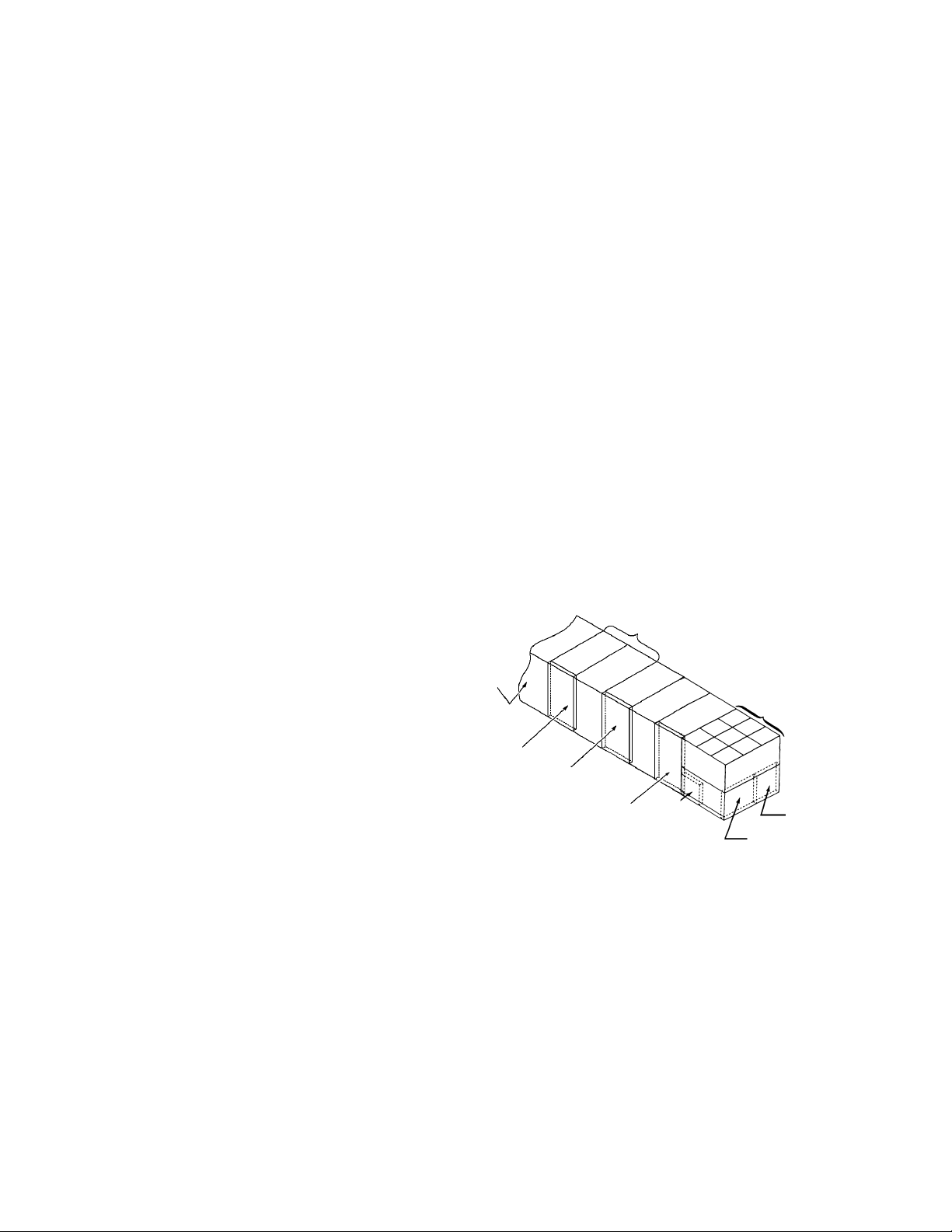
Unit Section Layout Examples
A=
Return Air/Outside Air/
Heat Recovery/Prop Exhaust
Section
B C F G
A
Prop Exhaust Draw Thru
A
Heat Recovery Draw Thru Heat Recovery Blow Thru
A
B, C, D, E=
Draw-Thru Section
D
B C F G
D
H J
H J
RFS RCS
B C F G
D
F=
Supply Fan
Section
K M
L
K M
H
J K
G, H, I=
Blow-Thru Section
RPS
A
J=
Final
Filter
B C F G
A
K=
Discharge
Plenum
D
Return Air Fan Draw Thru
B C F
L=
Out-of Air-
Stream
Blank Ac-
cess
H
H J
G
M
M=
Condenser Section
J K M
I
K M
Return Air Fan Draw Thru
RDT
A
RoofPak Singlezone; RCS,RDT,RFS,RPS 080-135 “C” Rev. AD 07/12 RPL 700007000 / Page 8
B C F
With Prop Exhaust With Return Air Fan
D
E
M
A
B C F
D
E
M
Page 9
Nomenclature
Continued
General Options
Unit Model Codes that Pertain: 05, 06, 07, 51- 54
Section A
Return/Outside Air/Heat Recovery Options
Unit Model Codes that Pertain:
14, 15, 19, 20, 21, 22, 23, 24, 49
Sections B, C, D, E
Draw-Thru Cooling Sections
Section B- Filter
Unit Model Codes that Pertain: 25
Section C- Draw-Thru Blank Access
Unit Model Codes that Pertain: 26
Section D- Draw-Thru Cooling Section
Unit Model Codes that Pertain: 27, 28, 29
Section E- Draw-Thru Heating/Blank Section
Unit Model Codes that Pertain: 30
Section F- Supply Fan Options
Unit Model Codes that Pertain:
14, 15, 31, 32, 33, 49
Sections G, H, I
Blow-Thru Options (N/A RDT)
Section G= Blow-Thru Heat/Blank
Unit Model Codes that Pertain: 04, 34
Section J- Final Filter Section
Unit Model Codes that Pertain: 39
Section K- Discharge Plenum Section
Unit Model Codes that Pertain: 40
Section L- Blank Compartment Section- Out of
Airstream
Unit Model Codes that Pertain: 41
Section M- Condenser Section
Unit Model Codes that Pertain: 42, 43, 44, 45, 47
Section N- Main Control Panel
Unit Model Codes that Pertain: 08, 09, 10, 11, 12, 18
Auxiliary Controls/ Remote Sensors
Unit Model Codes that Pertain: 13, 16, 17
Refrigeration Tubing Options
Unit Model Codes that Pertain: 46
Supply Air Section
Prop Exhaust
(not shown)
Condenser
Section
Section H= Blow-Thru Blank Access
Unit Model Codes that Pertain: 38
Section I- Blow-Thru Coil Sections
Unit Model Codes that Pertain: 35, 36, 37
Inverters, Line Reactors
& Manual Bypass
Electric Heat
Contol Panel
Main Control
Panel
Fuse
Box
Condenser
Control
Panel
Condenser Control
Panel
RoofPak Singlezone; RCS,RDT,RFS,RPS 080-135 “C” Rev. AD 07/12 RPL 700007000 / Page 9
Page 10

Nomenclature
Continued
Code 04= Heat Section- Type of Heat
Y= No Heat
A= Natural Gas Heat
E= Electric Heat
S= Steam Heat
W= Hot Water Heat
X= Propane Heat or Fuel Oil Furnace (specials)
Code 05= Split Unit
C= Split at condenser
F= Split at Fan/Heat
Code 06= Insulation and Liners
1= 1”, 3/4# with liners on doors
2= 1½”, 1.5# with solid liners on doors & ceilings
3= 1½”, 1.5# with perforated liners in plenums, solid elsewhere
4= 1½”, 1.5# with solid liners on doors, ceilings and floors
5= 1½”, 1.5# with perforated liners in plenums, solid elsewhere
(including floors)
6= 1½”, 1.5# with St Stl Solid Liners on Doors, Ceilings and Floors
Code 07= Approval agency listing
CY= ETL-Canada
EY= USA
YY= None
Code 08= Main Control Box Location
P= Discharge Plenum MicroTech (2 panel)
D= Discharge Plenum MicroTech (1 panel)
S= Supply Fan (2 panel)
F= Supply Fan (1 panel)
C or B= Vestibule
H or T= Heat Section
Code 09= Unit Voltage
12= 208/60/3
27= 460/60/3
28= 380/50/3
29= 230/60/3
37= 575/60/3
Code 10= Starting Option
AL= Across-the-Line (std.)
PW= Part Winding Start
PP= Part Winding Compressor & Fan
PS= Part Winding Fans
Code 12= Temperature Controls (continued)
MicroTech II
LD= LonMark w/ Discharge Air Temp. Ctl.
LS= LonMark w/ Space or Zone Ctl.
BD= BACNet w/MSTP w/ Discharge Air Temp. Ctl.
BS= BACNet w/MSTP w/ Space or Zone Ctl.
ED= BACNet w/Ethernet w/ Discharge Air Temp. Ctl.
ES= BACNet w/Ethernet w/ Space or Zone Ctl.
SD= Standalone w/ Discharge Air Temp. Ctl.
SS= Standalone w/ Space or Zone Ctl.
MicroTech III
LE= LonMark w/ Discharge Air Temp. Ctl.
LF= LonMark w/ Space or Zone Ctl.
BE= BACNet w/MSTP w/ Discharge Air Temp. Ctl.
BF= BACNet w/MSTP w/ Space or Zone Ctl.
EE= BACNet w/Ethernet w/ Discharge Air Temp. Ctl.
EF= BACNet w/Ethernet w/ Space or Zone Ctl.
SE= Standalone w/ Discharge Air Temp. Ctl.
SF= Standalone w/ Space or Zone Ctl.
No Controls
YM= No Temperature Controls
YC= No Temperature Controls w/6 to 9 volt DC modulating gas heat
actuator
Code 13= Air Flow Controls
Y= None
1= 1 duct sensor
2= 2 duct sensors
3= 1 duct and 1 space sensor
4= 1 space sensor
5= Duct Hi Limit (DHL) sensor for no controls unit- VAV unit only
Code 14= Inverters
Y= None
X=VAV (special)
Separate Section
1= SA Fan only w/bypass
2= SA & RA Fans w/bypass
4= RA only w/bypass
No Separate Section
3= SA Fan only w/bypass
5= SA & RA Fans w/bypass
6= SA Fan only no bypass
7= SA & RA Fans no bypass
8= RA Fan only w/bypass
9= RA Fan only no bypass
Code 11= Field Power Connection and Disconnect
P1= Single Power Block: Complete Unit
Q1= Two Power Blocks: EH/Balance of Unit
A2= One, thru-the-door Disconnect: Complete Unit
C2= Two, thru-the-door Disconnects: SAF&RAF&CB/Balance of Unit
B2= Two, thru-the-door Disconnects: EHB/Balance of Unit
D2= Three thru-the-door Disconnects: EH/SAF&RAF&CB/Balance of
Unit
Code 12= Temperature Controls
Original MicroTech
1M= MicroTech, CAV, Zone Control
2M= MicroTech, VAV, Discharge Air Cooling Control, Zone/Return Air
Heating Control (Constant Volume)
4M= MicroTech, VAV, Disch. Air Cool and Heating Control
5M= MicroTech, CAV, Disch. Air Cooling or Cool & Heat Control
Code 15= Inlet Vane/Damper Actuators or Inverter Type
Y= None
1= Supply Fan Only
2= Supply and Return Fan
4= Return Fan Only
A= ABB Inverter
G= Graham Inverter
R= Reliance Inverter
S= McQuay MD2, MD3, MD6
F= Field Installed Inverter controlled by MTech II or III
Code 16= Smoke Detectors
1= Return Air Smoke Detector
2= Supply Air Smoke Detector
3= 1 + 2
Y= None
RoofPak Singlezone; RCS,RDT,RFS,RPS 080-135 “C” Rev. AD 07/12 RPL 700007000 / Page 10
Page 11

Nomenclature
Continued
Code 17= Misc. Aux. Controls
C G
Y= None
F= Freezestat (Steam or HW Heat only)
P= Phase Failure
G= Ground Fault Protection
L= Line Reactors (Inverter w/ separate section only)
A= Freezestat & Phase Failure (Steam or HW Heat only)
B= Freezestat & Ground Fault (Steam or HW Heat only)
C= Phase Failure & Ground Fault
D= Freezestat, Phase Failure & Ground Fault
(Steam or HW Heat only)
E= Freezestat & Line Reactors
(Steam or HW Heat & Inverter w/ separate section only)
H= Phase Failure & LIne Reactors
(Inverter w/ separate section only)
J= Freezestat, P.F. & Line Reactors
(ST or HW Heat & Inverter w/ separate section only)
K= Ground Fault, Phase Failure & Line Reactors
(Inverter w/ separate section only)
1= UV Lights
2= UV Lights & Freezestat
(Steam or HW Heat only)
3= UV Lights & Phase Failure
4= UV Lights & Line Reactors
(Inverter w/ separate section only)
5= UV Lights, Freezestat & Phase Failure
(Steam or HW Heat only)
6= UV Lights, Freezestat & Line Reactors
(ST or HW Heat & Inv. w/ sep. section only)
7= UV Lights, Phase Failure & Line Reactors
(Inverter w/ separate section only)
8= UV Lights, Freezestat, Phase Failure & Line
C= Differential Enthalpy
Y= None (includes mechanical enthalpy)
Code 18= Misc. Controls/ Unit Length
YYYY= None
MicroTech I
KYYY= Unit mounted keypad
BYYY= Unit mounted keypad and modem
MicroTech II or MicroTech III
W___= Wireless Modem (___= Air Handler Length [in.])
M___= Phone Modem (___= Air Handler Length [in.])
R___= Remote Keypad (___= Air Handler Length [in.])
K___= Remote Keypad (___= Air Handler Length [in.])
U___= Unit Powered Receptacle (___= Air Handler Length [in.])
V___= K + U (___= Air Handler Length [in.])
Code 19= Return Air Plenum
YY= None (No return air section)
BY= Bottom Return
HY= Back Return
SY= Side (opp. drive) Return
BE= Bottom Return w/Iso. Damper w/ Actuator
BB= Bottom Return w/Burgler Bars
Code 20= Outdoor Air Options
YY= None
AE= 100% Outside air damper w/hood & actuator
AY= 100% Outside air damper w/hood/no actuator
BE= 0- 30% Outdoor air section w/actuator
BY= 0- 30% Outdoor air section w/o actuator
DE= 0- 100% Econ. w/barometric exhaust damper w/act.
DY= 0- 100% Econ. w/barometric exhaust damper w/o act.
EE= 0- 100% Econ. w/power closure exhaust damper w/act.
EY= 0- 100% Econ. w/power closure exhaust damper w/o act.
HE= 0- 100% Econ. w/prop exhaust damper w/act.
HY= 0- 100% Econ. w/prop exhaust damper w/o act.
FE= same as DE + Design Flow
FY= same as DY + Design Flow
GE= same as EE + Design Flow
GY= same as EY + Design Flow
JE= same as HE + Design Flow
JY= same as HY + Design Flow
KE= same as DE + Ebtron Sensor
KY= same as DY + Ebtron Sensor
LE= same as EE + Ebtron Sensor
LY= same as EY + Ebtron Sensor
ME= same as HE + Ebtron Sensor
MY= same as HY + Ebtron Sensor
Code 21= Return Air Fan
YYYY= No Return Air Fan
44B()= 44” Airfoil w/o vanes
44W()= 44” Airfoil w/vanes
()= isolator type:
1= rubber in-shear
2= spring
3= spring w/seismic restraints
Code 22= Return Air Fan Motor
YYY= No Return Fan
J K Y
Always Y
A= Open Drip-proof motor
E= High Eff. ODP motor
F= High Eff. VAV motor
G= Totally- Enclosed motor
H= High Eff. Totally-Enclosed
J= Premium Eff. ODP
K= Premium Eff. Totally- Encl.
J= 5.0 HP P= 25.0 HP
K= 7.5 HP Q= 30.0 HP
L= 10.0 HP R= 40.0 HP
M= 15.0 HP S= 50.0 HP
N= 20.0 HP T= 60.0HP
(prop exhaust option is always J [5.0 HP])
RoofPak Singlezone; RCS,RDT,RFS,RPS 080-135 “C” Rev. AD 07/12 RPL 700007000 / Page 11
Page 12

Nomenclature
Continued
Code 23= Return Air Fan Drive Selection
YYYY= No Return Air Fan
_ _ _ _ A
Service Factor/Pitch Type
Required
RPM
A= Std. SF/Fixed Pitch
B= 150% SF/Fixed Pitch
C= Std. SF/Variable Pitch
D= 150% SF/Variable Pitch
Code 24= Exhaust Fans
Y= None
2= 2 Prop Exhaust Fan w/ Hood
3= 3 Prop Exhaust Fans w/ Hood
Code 25= Draw-Thru Filter Section
AA= Angular/Throwaway
AB= Angular/30% Throwaway
AC= Angular/30%/Intersept
AY= Angular/No Media
DB= Angular w/LO CFM Blender/30% Throwaway
DC= Angular w/LO CFM Blender/30%/Intersept
DY= Angular w/LO CFM Blender/No Media
EB= Angular w/HI CFM Blender/30% Throwaway
EC= Angular w/HI CFM Blender/30%/Intersept
EY= Angular w/HI CFM Blender/No Media
FA= Flat/ Throwaway
FB= Flat/ 30%/Throwaway
FC=Flat/30%/Intersept
FD= Flat/65% Cartridge
FE= Flat/95% Cartridge
FG= Flat/95% Cartridge/Intersept
FY= Flat/Rack Only
HB= Flat w/HI CFM Blender/30%Throwaway
HC= Flat w/HI CFM Blender/30%/Intersept
HD= Flat w/HI CFM Blender/65% Cartridge
HE= Flat w/HI CFM Blender/95% Cartridge
HG= Flat w/HI CFM Blender/95% Cartridge/ Intersept
HY= Flat w/HI CFM Blender/Rack Only
LE= Large Staggered/95% Cartridge
LG= Large Staggered/95% Cartridge/Intersept
LY= Large Staggered/Rack Only
SD= Staggered 65% Cartridge
SE= Staggered 95% Cartridge
SG= Staggered 95% Cartridge/Intersept
SY= Staggered Rack Only
VD= Staggered w/HI CFM Blender/65% Cartridge
VE= Staggered w/HI CFM Blender/95% Cartridge
VG= Staggered w/HI CFM Blender/95% Cartridge/Intersept
VY= Staggered w/HI CFM Blender/Rack Only
BY= Blank 24” Section- less filters and rack
CY= Blank 48” Section- less filters and rack
Code 26= Blank Draw-thru Section
Y= None
S= Blank 48” Section
Code 27= Draw-Thru Drain Pan/Cooling Coil Section
RPS/RFS/RDT
YYYY= None
CYYS= Cooling coil section w/stainless steel sloped drain pan
CYYY= Cooling coil section w/galvanized steel sloped drain pan
Code 28= Draw-Thru Cooling Coil
YYYYYY= No Cooling Coil
5Z 08 3 H
H= Aluminum Fin
D= Lanced Aluminum
C= Copper Fin
3= 3 Row 5= 5 Row
4= 4 Row 6= 6 Row
08= 8 Fins-per-inch
10= 10 Fins-per-inch
12= 12 Fins-per-inch
4Z= Type 4EZ
5Z= Type 5EZ
Code 29= Draw-Thru Heating Coil
YYYYYY= No Heating Coil (always)
Code 30= Draw-Thru Heating Section (RDT only) or Blank Spacer
Section
YYYYYY= No Heating Section
BBBBBB= Blank 48” Section
Hydronic Heat (RDT only)
W22 J 3 E
E= Electric Actuator
Y= Less Actuator
2= 2 Way Steam Valve
3= 3 Way HW Valve
Y= No Valve
E= 1¼” Valve Pkg. H= 2½” Valve Pkg.
F= 1½” Valve Pkg. J= 3.0” Valve Pkg.
G= 2.0” Valve Pkg. Y= No Valve Pkg.
S11= 5JA0601H (6FPI, 1 Row 5J Steam Coil)
S12= 5JA1201H (12FPI, 1 Row 5J Steam Coil)
S13= 5JA0602C (6FPI, 2 Row 5J Steam Coil)
S14= 5JA1202C (12FPI, 2 Row 5JSteam Coil)
W11= 5WH0901H (9FPI, 1 Row 5WH HW Coil)
W22= 5WS0902C (9FPI, 2 Row 5 WS HW Coil)
Electric Heat (RDT only)
E120 2 Y
Always ‘Y’
1= 1 Stage 2= 2 Stages
4= 4 Stages 6= 6 Stages
E020= 20 KW Heater E160= 160 KW Heater
E040= 40 KW Heater E200= 200 KW Heater
E060= 60 KW Heater E240= 240 KW Heater
E080= 80 KW Heater E280= 280 KW Heater
E100= 100 KW Heater E320= 320 KW Heater
E120= 120 KW Heater
RoofPak Singlezone; RCS,RDT,RFS,RPS 080-135 “C” Rev. AD 07/12 RPL 700007000 / Page 12
Page 13

Nomenclature
Continued
Code 31= Supply Air Fan
33A()= 33” Airfoil Double Width, w/o vanes
33V()= 33” Airfoil Double Width, w/vanes
33F()= 33” Forward Curved, LP
33M()= 33”Forward Curved, MP
36A()= 36” Airfoil Double Width, w/o vanes
36V()= 36” Airfoil Double Width, w/vanes
36F()= 36” Forward Curved, LP
36M()= 36”Forward Curved, MP
40A()= 40” Airfoil Double Width, w/o vanes
40V()= 40” Airfoil Double Width, w/vanes
44B()= 44” Airfoil Single Width, w/o vanes (RDT only)
44W()= 44” Airfoil Single Width, w/vanes (RDT only)
49B()= 49” Airfoil Single Width, w/o vanes (RDT only)
49W()= 49” Airfoil Single Width, w/vanes (RDT only)
()= Fan Isolators: 1= RIS; 2= Spring; 3= Spring w/ Seismic Snubbers
Code 32= Supply Air Fan Motor
E A Y
Always ‘Y’
A= Open Drip-proof Motor
E= High Eff. ODP Motor
F= High Eff. VAV
G= Totally- Enclosed Motor
H= High Eff. Totally-Enclosed
J= Premium Eff. ODP Motor
K= Premium Eff. Totally-Enclosed
J= 5.0 HP M= 15.0 HP Q= 30.0 HP T= 60.0 HP
K= 7.5 HP N= 20.0 HP R= 40.0 HP U= 75.0 HP
L= 10.0 HP P= 25.0 HP S= 50.0 HP
Code 33= Supply Air Fan Drive Selection
_ _ _ _ A
Service Factor/Pitch Type
Required
RPM
A= Std. SF/Fixed Pitch
B= 150% SF/Fixed Pitch
C= Std. SF/Variable Pitch
D= 150% SF/Variable Pitch
Code 34= Blow Thru Heat Section
YYYYYY= No section, cooling only
BBBBBB= Blank 48” section, no heat, cooling only
Gas Heat Breakdown:
079 S S C
A= Low CFM Baffle Position
B= Medium CFM Baffle Position
C= High CFM Baffle Position
D= Extra High CFM
Y= None
A= One Stage Heat/Maximum gas pressure= 0.5 psi
P= One Stage Heat/ with H.P. Regulator Range= 2- 3 psi
Q= One Stage Heat/ with H.P. Regulator Range= 5- 10 psi
E= Modulating Burner/Maximum gas pressure= 0.5 psi
R= Modulating Burner/with H.P. Regulator Range= 2- 3 psi
S= Modulating Burner/with H.P. Regulator Range= 5- 10 psi
H= Hi Turn Down Burner 20:1
T= Hi Turn Down Burner 20:1/with H.P. Regulator Range= 2- 3 psi
U= Hi Turn Down Burner 20:1/with H.P. Regulator Range= 5- 10
psi
A= Aluminized Steel Secondary Heat Exchanger
S= Stainless Steel Heat Exchanger
MBH (in 10’s)
ex. 065= 650 MBH [050,064,065,079,080,100110,140,150,200]
Code 34= Blow Thru Heat Section (continued)
Hydronic Heat Breakdown:
W22 J 3 E
E= Electric Actuator
Y= Less Actuator
2= 2 Way Steam Valve
3= 3 Way HW Valve
Y= No Valve
E= 1¼” Valve Pkg. H= 2½” Valve Pkg.
F= 1½” Valve Pkg. J= 3.0” Valve Pkg.
G= 2.0” Valve Pkg. Y= No Valve Pkg.
S11= 5JA0601H (6FPI, 1 Row 5J Steam Coil)
S12= 5JA1201H (12FPI, 1 Row 5J Steam Coil)
S13= 5JA0602C (6FPI, 2 Row 5J Steam Coil)
S14= 5JA1202C (12FPI, 2 Row 5JSteam Coil)
W11= 5WH0901H (9FPI, 1 Row 5WH HW Coil)
W22= 5WS0902C (9FPI, 2 Row 5 WS HW Coil)
Electric Heat Breakdown:
E020 1 Y
Always ‘Y’
1= 1 Stage 4= 4 Stages
2= 2 Stages 6= 6 Stages
E020= 20 KW Heater E200= 200 KW Heater
E040= 40 KW Heater E240= 240 KW Heater
E060= 60 KW Heater E280= 280 KW Heater
E080= 80 KW Heater E320= 320 KW Heater
E100= 100 KW Heater
E120= 120 KW Heater
E160= 160 KW Heater
Code 35= Draw-Thru Drain Pan/Cooling/Heating Coil Section
RPS/RFS
YYYY= None
CYYS= Cooling coil section w/stainless steel drain pan
CYYY= Cooling coil section w/galvanized steel drain pan
DYYS= Stainless Steel Drain pan only (48” blank section)
DYYY= Galvanized Steel Drain pan only (48” blank section)
YYYY= None
Code 36= Draw-Thru Cooling Coil
YYYYYY= No Cooling Coil
5Z 08 3 H
H= Aluminum Fin
D= Lanced Aluminum
C= Copper Fin
3= 3 Row 5= 5 Row
4= 4 Row 6= 6 Row
08= 8 Fins-per-inch
10= 10 Fins-per-inch
12= 12 Fins-per-inch
4Z= Type 4EZ
5Z= Type 5EZ
Code 37= Draw-Thru Heating Coil
YYYYYY= No Heating Coil (always)
Code 38= Blow-Thru Blank Access Section
Y= None- no section
B= Blank Section after Heat Section- 48” section
RoofPak Singlezone; RCS,RDT,RFS,RPS 080-135 “C” Rev. AD 07/12 RPL 700007000 / Page 13
Page 14

Nomenclature
Continued
Code 39= Final Filter Section
Y= None
A= Flat filter section, 95% cartridge, 24/24”
B= Flat filter section, 95% cartridge, 24/48”
C= Blank- 24/24” section
D= Blank- 24/48” section
E= Flat filter section, 95% cartridge, 24/24” with Intersept
F= Flat filter section, 95% cartridge, 24/48” with Intersept
Code 40= Discharge Plenum
BY= Bottom Discharge
GY= Bottom Discharge (SW Supply Fan Only)
BB= Bottom Discharge w/Burglar Bars
GB= Bottom Discharge w/Burglar Bars (SW Supply Fan Only)
BE= Bottom Discharge w/Discharge Damper (VAV) w/act.
FY= Front Discharge (RFS only)
SY= LH Side Discharge (SW Supply Fan only)
HY= LH Side Discharge (SW Supply Fan only)
Code 41= Blank Compartment Section- Out of Airstream
Y= None- no selection required
1= 48/24” Blank Section only- out of airstream with light
2= 48” Blank Section only- out of airstream with light
Code 42= Compressor Capacity Control
4= 4 steps
6= 6 steps
8= 8 steps
Code 43= Condenser Options
AY= Aluminum Fin Air Coil
AG= Aluminum Fin Air Coil w/ Coil Guards
AS= Aluminum Fin Air Coil w/ Seal Tite Conduits
AB= Alum. Fin Coil w/ Coil Guards & STC
CY= Copper Fin Air Coil
Code 47= Low Ambient Operation
1= Fantrol Standard Fans
2= Speedtrol Standard Fans
3= Fantrol Quiet Fans
4= Speedtrol Quiet Fans
5= Fantrol Standard CFM Fans w/TEAO Motor
6= Speedtrol Standard CFM Fans w/ TEAO Motor
7= Fantrol High CFM Fans w/ TEAO Motor
8= Speedtrol High CFM Fans w/ TEAO Motor
Code 48= Future use
Code 49= Supply and Return Fan Options
Y= None
A= SA fan belt guard
B= SA fan section light
C= A + B
D= SA & RA fan belt guard
E= SA & RA section light
F= D + E
Code 50= Misc.
Code 51= Packaging
Code 52= Parts Warranty
Code 53= Compressor Warranty
Code 54= Heat Exchanger Warranty
Code 44= Compressor Type
H= Semi Hermetic R22
K= Semi Hermetic R407C
Z= Scroll R22 (080-105 only)
T= Scroll R407C (080-105 only)
Code 45= Compressor Isolation
1= Resilient rubber-in-shear
2= Spring isolation
3= Seismic
Code 46= Piping Option
1= Hot Gas Bypass, circuit #1 only
2= Hot Gas Bypass, circuits 1 & 2
3= Replaceable Filter Drier Core
4= 1 + 3
5= 2 + 3
Y= None
RoofPak Singlezone; RCS,RDT,RFS,RPS 080-135 “C” Rev. AD 07/12 RPL 700007000 / Page 14
Page 15
Nomenclature
Continued
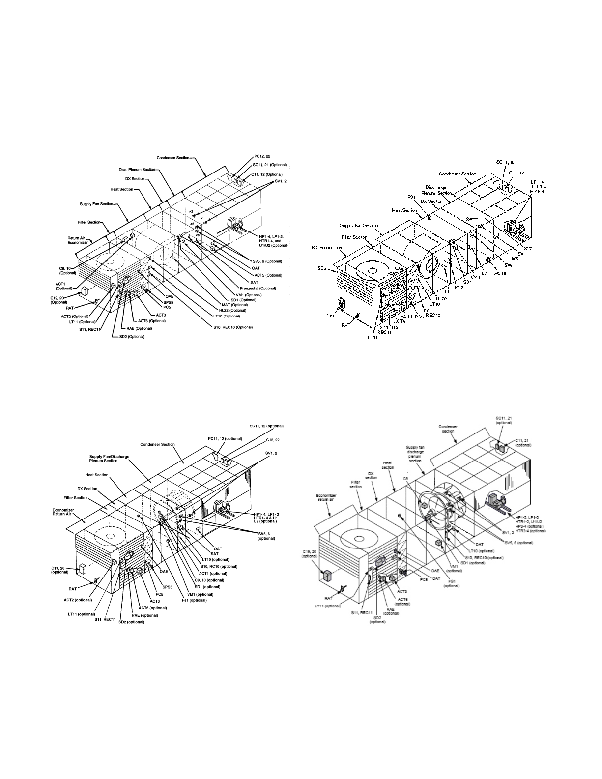
Control Locations
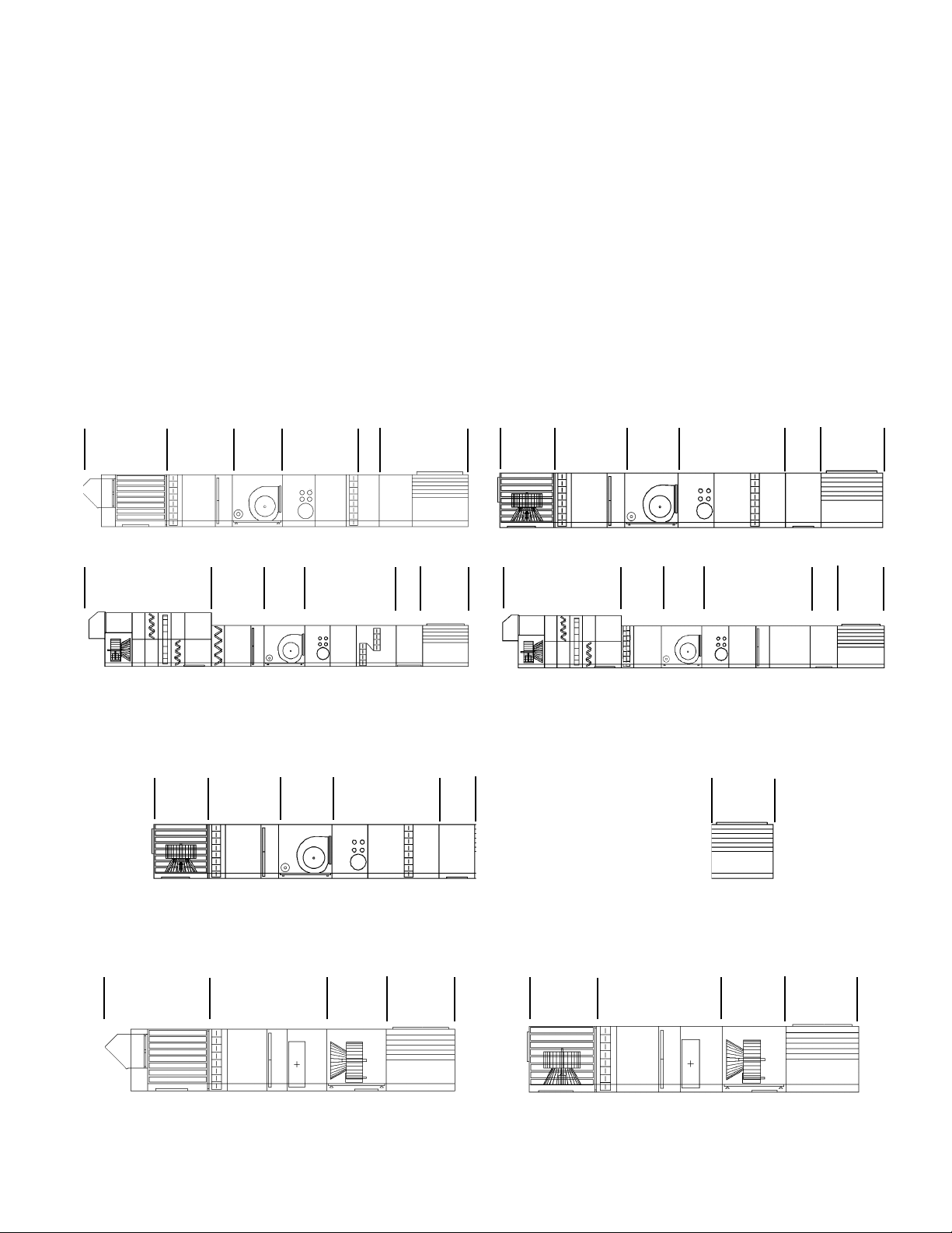
PC7 (located in Supply Air Section) is not
shown.
RPS, RFS, RCS - w/original controls & optional
vanes
RDT - w/original controls & optional vanes
RPS, RFS, RCS - MicroTech II or III controls
RDT - MicroTech II or III controls
RoofPak Singlezone; RCS,RDT,RFS,RPS 080-135 “C” Rev. AD 07/12 RPL 700007000 / Page 15
Page 16

Electrical Legend
Schematic Sym. Description Location
ACT1 Actuator Motor, Supply Fan Vanes Supply Air Section
ACT2 Actuator Motor, Return Fan Vanes Return Air Section
ACT3, 4 Actuator Motors, Economizer Dampers Economizer Section
ACT5 Actuator Motor, Discharge Isolation Damper Discharge Section
ACT6 Actuator Motor, Return Air Isolation Damper Return Air Section
ACT7 Actuator Motor, Heat Face/Bypass Coil Section, Heat
ACT8 Actuator Motor, Cool Face/Bypass Coil Section, Cool
ACT 10, 11 Actuator Motors, Exhaust Dampers Return Air Section
ADI ADI Board Main Control Box
AFD10 Adjustable Frequency Drive (Inverter), Supply Fan AFD or Supply Fan Sect.
AFD20 Adjustable Frequency Drive (Inverter), Return Fan AFD or Supply Fan Sect.
AS Blower Air Switch Furnace Section
BM Burner Blower Motor Furnace Section
C1-5 Power Factor Capacitors, Compressor #1 Condenser Section
C2, 6 Power Factor Capacitors, Compressor #2 Condenser Section
C3, 7 Power Factor Capacitors, Compressor #3 Condenser Section
C4, 8 Power Factor Capacitors, Compressor #4 Condenser Section
C9, 10 Power Factor Capacitors, Supply Fan Supply Air Section
C11 Capacitor, Speedtrol (Circuit #1) Cond. Bulkhead
C19, 20 Power Factor Capacitors, Return Fan Return Air Fan
C21 Capacitor, Speedtrol (Circuit #2) Cond. Bulkhead
CB10 Circuit Breaker, Supply Fan Main Control Box
CB20 Circuit Breaker, Return Fan Main Control Box
CCB1, 2 Compressor Control Boards Main or Cond. Ctl. Box
COMPR.1-4 Compressors Condenser Section
CPC Circuit Board, Main, MicroTech Controller Main Control Box
CPR Circuit Board, expansion, Main Controller Main Control Box
CS1, 2 Control Switches, Refrigerant Circuits Condenser Control Box
DAT Discharge Air Temperature Sensor Discharge section
DB1 Daughter Board Main Control Box
DFLH Design Flow Sensor, Left Hand Return Section
DFRH Design Flow Sensor, Right Hand Return Section
DHL Duct High Limit Main Control Box
DS1 Disconnect, Total Unit or Condenser/Heat Main Control Box
DS2 Disconnect, SAF/RAF/Controls Main Control Box
DS3 Disconnect, Electric Heat Electric Heat Section
DS4 Disconnect, Condenser Cond. Control Box
DS6 Disconnect, Unit Supplied 120V Power Bulkhead
EFT Entering Air Temperature Sensor Supply Fan Section
EHB1 Staged Electric Heat Board Main Control Box
EXPA, B, D Expansion Board Main Control Box
F1, 1A Fuse, Control Circuit, T1 Primary Main Control Box
F1C Fuse, Control Circuit, T1 Secondary Main Control Box
F2 Fuse, Control Circuit Condenser Control Box
F3 Fuse, Burner Motor Main Control Box
F4 Fuse, T4 Transformer Main Control Box
F11 Fuse, Speedtrol Motor Main Control Box
F12 Fuse, 208V Speedtrol Motor Main Control Box
FB1 - 4 Fuseblocks, Compressors Condenser/Fuse Ctrl Box
FB8 Fuseblock, Main Transformer Main Control Box
FB9, 10 Fuseblocks, Supply Fan Main Control Box
FB11-18 Fuseblocks, Condenser Fans Cond. Control Box
FB19, 20 Fuseblocks, Return Fan Main Control Box
FB31-40 Fuseblocks, Electric Heat (Top Bank) Electric Heat Section
RoofPak Singlezone; RCS,RDT,RFS,RPS 080-135 “C” Rev. AD 07/12 RPL 700007000 / Page 16
Page 17

Electrical Legend
Continued
Schematic Sym. Description Location
FB41-50 Fuseblocks, Electric Heat (Bottom Bank) Electric Heat Section
FD Flame Detector Furnace Section
FLC Fan Limit Control Furnace Section
FS1 Freezestat Coil Section, Heat/Cool
FSG Flame Safeguard Furnace Section
GCB1 Generic Condenser Board Main Control Box
GFS1/GFR1 Ground Fault Sensor/Relay, RPS Unit Main Control Box
GFS2/GFR2 Ground Fault Sensor/Relay, RCS Unit Cond. Control Box
GFS4/GFR4 Ground Fault Sensor/Relay, RCS Unit Cond. Control Box
GRD Ground All Control Boxes
GV1 Gas Valve, Pilot Furnace Section
GV2, 3 Gas Valves, Main Furnace Section
GV4-8 Gas Valve, Hi-Turn Down Furnace Section
HL 1-10 High Limits, Elec. Heaters, Power (Top Bank) Electric Heat Section
HL 11-20 High Limits, Elec. Heaters, Power (Bottom Bank) Electric Heat Section
HL22 High Limit, Gas Heat (Prefilters) Supply Air Section
HL23 High Limit, Gas Heat (Final Filter) Final Filter Section
HL31-40 High Limits, Elec. Heaters, Control (Top Bank) Electric Heat Section
HL41-50 High Limits, Elec. Heaters, Control (Bottom Bank) Electric Heat Section
HP1-4 High Pressure Controls, Refrigerant On Compressors
HP5 High Pressure Control, Gas Furnace Section
HS1 Heat Switch, Electric, Shutdown Main Control Box
HTR1-4 Crankcase Heaters On Compressors
IT Ignition Transformer Furnace Section
LP1,2 Low Pressure Controls, Refrigerant On Compr.
LP5 Low Pressure Control, Gas Furnace Section
LT2 Light, Furnace On Furnace Section
LT3 Light, Pilot Gas Valve On Furnace Section
LT4 Light, Main Gas Valve On Furnace Section
LT10 Light, Supply Fan Supply Air Section
LT11 Light, Return Fan Return Air Section
LT12 Light, Heat Section Heat Section
LT13 Light, Filter Section Filter Section
LT14 Light, Final Filter Section Final Filter Section
LT15 Light, Discharge Section Discharge Section
LT16 Light, Blow-through Coil Section Blow-thru Coil Section
LT17 Light, Evaporator Coil Section Evaporator Coil Section
LT18 Light, Preheat Section Preheat Section
LT19 Light, Blank Section Blank Section
LT20 Light, Blank Compartment Blank Compartment
LT22 Light, Condenser Section Condenser Section
M1-6 Contactors, Compressors Main/Cond. Control Box
M9, 10 Contactors, Supply Fan Main Control Box
M11-18 Contactors, Condenser Fans, Circuit #1 Cond. Control Box
M19,20 Contactors, Return Fan Main Control Box
M21-28 Contactors, Condenser Fans, Circuit #2 Cond. Control Box
M29 Contactor, Burner Motor Furnace Section
M30 Contactor, Supply Fan Inverter Inverter Bypass Box
M31-39 Contactors, Elec. Heaters (Top Bank) Electric Heat Section
M40 Contactor, Return Fan Inverter Inverter Bypass Box
M41-50 Contactors, Elec. Heaters (Bottom Bank) Electric Heat Section
M51, 52, 53 Contactor, Prop Exhaust Fan Motor Return Air Section
RoofPak Singlezone; RCS,RDT,RFS,RPS 080-135 “C” Rev. AD 07/12 RPL 700007000 / Page 17
Page 18

Electrical Legend
Continued
Schematic Sym. Description Location
MAT Mixed Air Temperature Sensor Supply Air Section
MCB Microprocessor Control Board Main Control Box
MCB1 Microprocessor Control Board #1 Main Control Box
MJ Mechanical Jumpers Terminal Blocks
MMP1-6 Manual Motor Protectors, Compressors Main/Cond. Control Box
MMP10 Manual Motor Protector, Supply Fan Main Control Box
MMP11, 12 Manual Motor Protectors, Condenser Fans Ckt. 1 Main/Cond. Control Box
MMP20 Manual Motor Protector, Return fan Main Control Box
MMP21,22 Manual Motor Protectors, Condenser Fans Ckt. 2 Main/Cond. Control Box
MMP51, 52, 53 Manual Motor Protectors, Prop Exhaust Fan Motors Return Air Section
MP1-4 Motor Protectors, Compressors On Compressors
NB1, 2 Neutral Blocks Main Control Box
NB3 Neutral Block Cond. Control Box
OAE Outside Air Enthalpy Control Economizer Section
OAT Outside Air Temperature Sensor Discharge Bulkhead
OBA Output Board A, Standard Main Control Box
OBB Output Board B, Cooling Main Control Box
OBC Output Board C, Heating Main Control Box
OL9, 10 Overload Relays, Supply Fan Main Control Box
OL 19,20 Overload Relays, Return Fan Main Control Box
OL 51,52, 53 Overload Relays, Prop Exhaust Fan Return Air Section
OP1-4 Oil Pressure Controls, Compressors Condenser Section
PB1 Powerblock, Total Unit or Cond./Heat Main Control Box
PB2 Powerblock, SAF/RAF/Controls Main Control Box
PB3 Powerblock, Electric Heat Electric Heat Section
PB4 Powerblock, Condenser Cond. Control Box
PB9, 10 Powerblock, Supply Fan Unit Split Junction Box
PB19, 20 Powerblock, Return Fan Unit Split Junction Box
PB31 Power Block, DS3 Power Distribution Electric Heat Control Box
PB41 Powerblock, Power Distribution RCS Control Box
PC5 Pressure Control, Clogged Filter Filter Section
PC6 Pressure Control, Clogged Final Filter Final Filter Section
PC7 Pressure Control, Proof of Airflow Supply Air Filter
PC8 Pressure Control, Minimum Airflow Evaporator Coil Section
PC12, 22 Pressure Control, FanTrol Cond. Bulkhead
PM1 Phone Modem Main Control Box
PS1, 2 Pumpdown Switches, Refrigerant Circuits Cond. Control Box
PS3 Pumpdown Switch, Unit Main Control Box
PVM1 Phase Voltage Monitor, RPS Unit Main Control Box
PVM2, 4 Phase Voltage Monitor, RCS Unit Cond./Fuse Ctrl Box
R1, 2 Relays, High Pressure Reset Main/Cond. Control Box
R3, 4 Relays, Hi Pressure delay Main/Cond. Control Box
R5- 8 Relays, Compressor, Safety/Cool Fail Main/Cond. Control Box
R9, 10 Relays, Compressor Lockout Main/Cond. Control Box
R11, 12 Relays, Low Ambient Main/Cond. Control Box
R12, 13, 14 Relays, Condenser Fan <Main Control Box
R19, 20 Relays, Cool Failure Indicator Main Control Box
R20 Relay, Gas, Steam, Hot Water Heat Main Control Box
R21, 22 Relays, Gas Heat Furnace Section
R23 Relay, Gas Heat, Modulating Valve or Electric Heat Furnace Sect./Elec. Ht. CB
R24 Relay, Gas Heat Alarm Main Control Box
R25 Relay, Gas Heat Start, Supply Fan Inverter Main Control Box
RoofPak Singlezone; RCS,RDT,RFS,RPS 080-135 “C” Rev. AD 07/12 RPL 700007000 / Page 18
Page 19

Electrical Legend
Continued
Schematic Sym. Description Location
R26 Relay, Occupied/Unoccupied Main Control Box
R27 Relay, Exhaust Dampers Main Control Box
R28 Relay, Isolation Dampers Main Control Box
R29 Relay, Remote Fire Alarm Main Control Box
R30 Relay, Cool Valve w/ F&B Main Control Box
R45 Relay, UV Lights Main Control Box
R46, 47 Relays, Supply Fan Inverter increase/decrease Main Control Box
R48, 49 Relays, Return Fan Inverter increase/decrease Main Control Box
R62, 64 Relays, Special Main Control Box
R63 Relay, Duct Hi Limit Main Control Box
R66 Relay, RA Smoke Detector Main Control Box
R67 Relay, Supply Fan Enable Main Control Box
R68 Relay, Return Fan Enable Main Control Box
R69 Relay, Inverter Bypass VAV Box Interlock Main Control Box
R81-88 Relays, Smoke Main Control Box
RAE Return Air Enthalpy Sensor Return Air Section
RAT Return Air Temperature Sensor Return Air Section
REC1 Receptacle, Main Box Main Control Box
REC2 Receptacle, Condenser Box Cond. Control Box
REC3 Receptacle, Field Power, 115V Discharge Bulkhead
REC10-23 Receptacles, Cabinet Section Cabinet Sections
S1 Switch, System On/Off, RPS Unit Main Control Box
S2 Switch, System On/Off, RCS Unit Cond. Control Box
S3 Switch, Furnace On/Off Furnace Section
S4 Switch, Inverter Bypass On/Off Main Control Box
S6 Switch, Return Fan Vanes Adjustment Main Control Box
S7 Switch, Local On/Off/Auto to Controller Main Control Box
S10-22 Switches, Cabinet Section Lights Cabinet Sections
S40-45 Switches, Door Interlock, UV Lights Cabinet Sections
SAT Supply Air Temperature Sensor Discharge Section
SB1 Staging Board #1, Cooling Main Control Box
SB2 Staging Board #2, Heating Main Control Box
SC11 Speed Control, Circuit #1 Cond. Bulkhead
SC21 Speed Control, Circuit #2 Cond. Bulkhead
SD1 Smoke Detector, Supply Air Discharge Section
SD2 Smoke Detector, Return Air Return Air Section
SPS1, 2 Static Pressure Sensors, Duct or Building Main Control Box
SPS5 Static Pressure Sensor, Clogged Filter “” Filter Section
SPS6 Static Pressure Sensor, Clogged Final Filter Final Filter Section
SR1-3 Sequence Relays, Electric Heat Electric Heat Section
SV1-4 Solenoid Valves, Liquid Discharge Bulkhead
SV5-8 Solenoid Valves, Hot Gas Discharge Bulkhead
T1 Transformer, Main Control Main Control Box
T2 Transformer, Unit 24V Main Control Box
T3 Transformer, Controller, 18V Main Control Box
T4 Transformer, Exhaust Dampers Main Control Box
T5 Transformer, Electric Heat Electric Heat Section
T6 Transformer, Unit Supplied 120V Voltage Bulkhead
T7 Transformer, Gas Pilot Valve Furnace Section
T8 Transformer, Gas Main Valve Furnace Section
T9 Transformer, 24V Refrigerant Circuit Main Control Box
T10 Transformer, SpeedTrol, 24V Cond. Control Box
RoofPak Singlezone; RCS,RDT,RFS,RPS 080-135 “C” Rev. AD 07/12 RPL 700007000 / Page 19
Page 20

Electrical Legend
Continued
Schematic Sym. Description Location
T11 Transformer, Speedtrol, 230V Cond. Control Section
TB1 Terminal Block, 115V, Field Main/Cond. Control Box
TB2 Terminal Block, 24V, Field Main/Cond. Control Box
TB3,4 Terminal Blocks, Condenser Cond. Control Box
TB5 Terminal Block, 115V, Factory Main/Cond. Control Box
TB6 Terminal Block, 115V/24V, Factory Main Control Box
TB7, 8 Terminal Block, 24V, Factory Main Control Box
TB10 Terminal Block, Heating Main Control Box
TB11 Terminal Block, Heating Electric Heat Section
TB12, 13 Terminal Blocks, Electric Heat, Power Electric Heat Section
TB25 Terminal 115V Factory Unit Split Junction Box
TB27, 28 Terminal 24V Factory Unit Split Junction Box
TC1, 2 Temperature Controls, FanTrol Cond. Control Box
TC12 Temperature Control, Fantrol Cond. Control Box
TD1, 2 Time Delays, Compressor Lockout Main/Cond. Control Box
TD3, 4 Time Delays, High Pressure Main/Cond. Control Box
TD5- 8 Time Delays, Compressor Part Winding Cond. Control Box
TD9 Time Delay, Supply Fan Part Winding Main Control Box
TD10 Time Delay, Hi-Turn Down Burner Furnace Section
TD11, 12 Time Delays, Low Ambient Cond. Control Box
TD19 Time Delays, Return Fan Part Winding Main Control Box
TD20 Time Delay, Return Air Fan Main Control Box
TR1, 2 Transducer, Pressure Main Control Box
U1,2 Unloaders, Compressors On Compressors
VM1 Valve Motor, Heating Heating Section
VM5 Valve Motor, Cooling Coil Section, Cool
VV1 Vent Valve Furnace Section
ZNT1 Zone Temperature Sensor, Control Field Installed
ZNT2-5 Zone Temperature Sensors, Special Field Installed
RoofPak Singlezone; RCS,RDT,RFS,RPS 080-135 “C” Rev. AD 07/12 RPL 700007000 / Page 20
Page 21

Section A- Outdoor/Return Air Section
Notes
➩
Primary Codes that pertain: 19, 20, 21, 22, 23
Additional Codes that pertain: 06, 09, 12, 14, 15, 16, 17, 49
Codes 19 and 20 determine the base section. Code 19 is the Return Air Plenum, and determines if the unit has
back (a.k.a. horizontal) return air, bottom return air, or side return air. The plenum is required for any outdoor air
application with an economizer (Code 20= BE, BY, DE, DY, EE, EY, FE, FY, GE, GY, HE, HY, JE or JY). The only
case in which a plenum is not required is when a 100% outdoor air damper and hood are ordered (C20= AE, AY).
Codes 21, 22, 23 determine the return air fan, motor and drives. These codes only pertain to units with a 0-100%
economizer (C20= DE, DY, EE, EY, FE, FY, GE, GY, HE, HY, JE or JY). The fan section parts, the fans, and the
motors are listed in this section. The drive components (fan sheave, motor sheave, belt, and fan bushing) are
not listed as they are unique to the unit. If a drive component is required you may use the number from the
part and cross reference it with the Drive Components Cross Reference form number: 571006, or contact
Daikin McQuay Parts to ensure that the needed part(s) are correctly identified. The motors range anywhere
from 5- 60 horsepower, and the fan wheel is 40”.
Code 06 determines the panels used in final cabinet assembly (return air units only). For sheet metal components
that make up the Outdoor/Return Air Section, contact Daikin McQuay Parts to insure that correct liners,
insulation and hardware are ordered.
Code 09, the voltage, is part of the motor part number identification.
Code 12, the control system comes into play when an economizer is present. The economizer comes with an actuator
motor on any MicroTech unit (C12= 1M, 2M, 4M, or 5M [original MicroTech] or L*, B*, E* or S* [MicroTech II or III]),
but may not have a motor if the unit has controls by others (C12= YC or YM).
Code 14 determines if the return fan has an inverter, or variable frequency drive. If code 14 equals 1-9 (or X for units
built prior to 2000) , then the unit has inverters, and cannot, therefore have wheels with variable inlet vanes (which
haven’t been used on production units since 2003).
Code 15, determines if Variable Inlet Vanes (VIV) are present (these haven’t been used on production units since
2003). If code 15= 2 or 4, they are present on the return fan.
Code 16 determines if a smoke detector is located in the return air cabinet. If C16= 1 or 3, a smoke detector (SD2)
is present.
Code 17 determines the Enthalpy Control. If C17= Y* and the unit has an economizer there is a mechanical enthalpy
control (OAE). If C17= C*, there is a differential enthalpy control (OAE + RAE).
Code 49 determines if the return air cabinet has a light, switch and receptacle (C49= B), fan belt guards (C49= D)
or both (C49= F).
RoofPak Singlezone; RCS,RDT,RFS,RPS 080-135 “C” Rev. AD 07/12 RPL 700007000 / Page 21
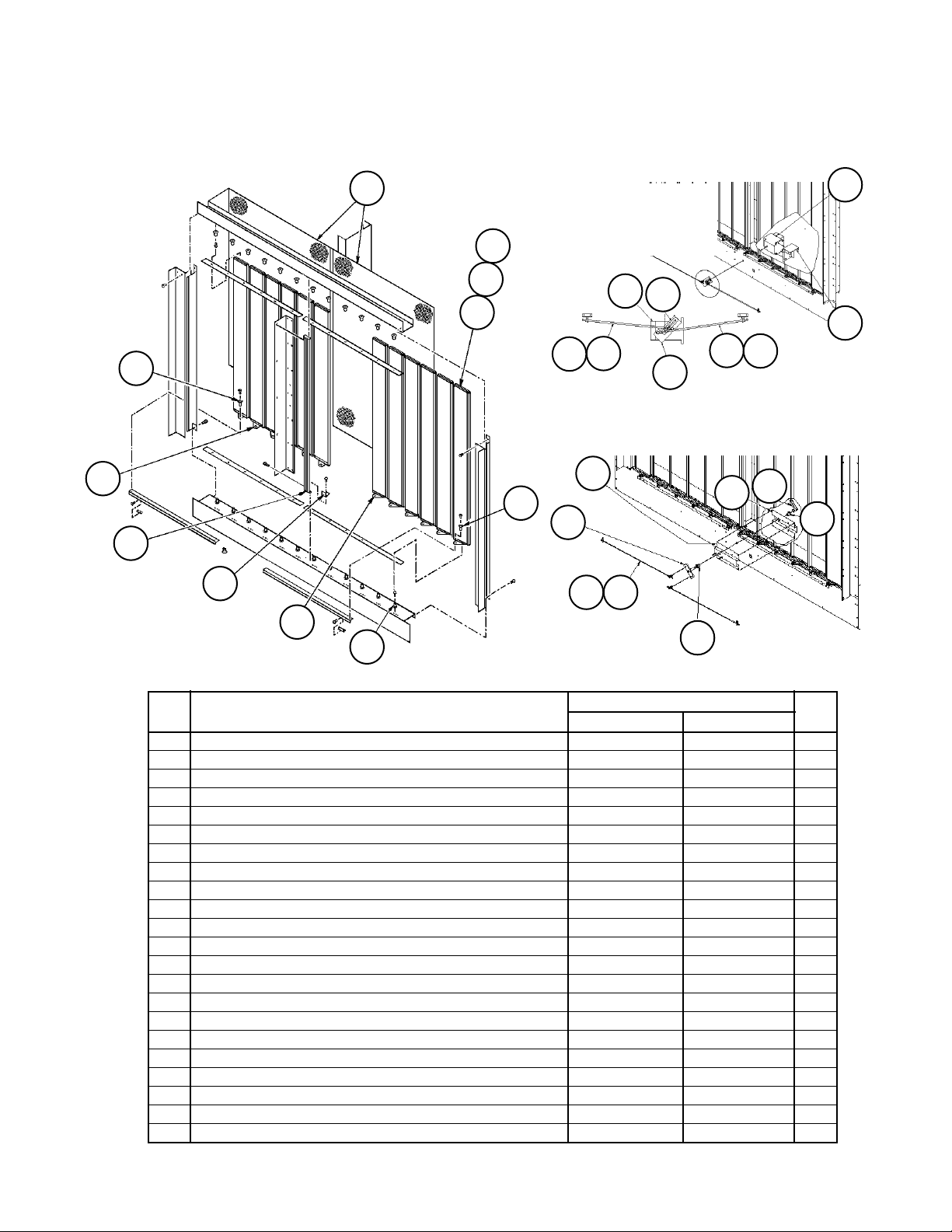
Page 22
Section A- Outdoor/Return Air Section
100% Outside Air Damper with Hood
C20= AE or AY and C19= YY
No Return Air Plenum
Air
Flow
11
15
14
13
12
9
4
Section B
9
10
15
Ref. Part Actuator Qty.
No. Description C20= AE C20= AY
4 Damper Assy 1 055979603 055979602 1
Damper Only 098313801 039813801 1
9 Liner 056132701 056132701 2
10 Panel- Hood Side 056132203 056132203 1
11 Panel- Hood Side 056132204 056132204 1
12 Panel- Hood Top 056131802 056131802 1
13 Louver 056132002 056132002 5
14 Channel- Support 056132403 056132403 2
15 Channel- Support 056132102 056132102 2
1
Complete assy includes the damper assy and linkage (no actuator) or actuator assy. For Damper components see the
following page.
Note: The outdoor air damper with actuator (C20= AE) must have MicroTech controls. Dampers without actuators (C20= AY)
must have controls by others (12= YM, YC).
RoofPak Singlezone; RCS,RDT,RFS,RPS 080-135 “C” Rev. AD 07/12 RPL 700007000 / Page 22
Page 23
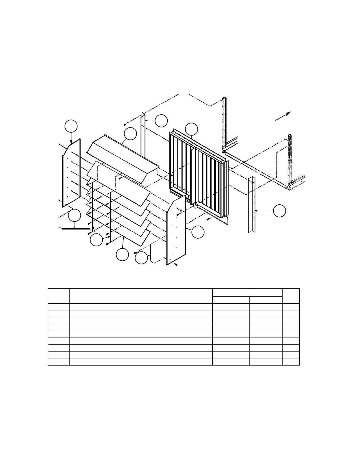
Section A- Outdoor/Return Air Section
100% Outside Air Damper
C20= AE or AY and C19= YY
23
29
26
16
Damper Assy Detail
28
14
24
13
25
27
Motorized Linkage
Detail:
C20= AE
22
21
4
Manual Linkage Detail:
17
23
5
7
21
20
6
C20= AY
40
21
10
22
17
4
20
40
Ref. Part Actuator Qty.
No. Description C20= AE C20= AY
4 Shaft- Linkage 055979701 not used 2
5 Shaft Assy not used 056081001 1
6 Adapter Plate- CrankArm 055542001 not used 1
7 Shaft- Linkage not used 055536609 2
10 Channel- Support not used 056080601 1
13 Blade- Damper 044195103 044195103 13
14 Grille 055982601 055982601 2
16 Stop/Anti- Rotate- Damper 065779801 065779801 2
17 Support- Damper Motor 055982001 not used 1
Support- Damper not used 056080701 1
20 Crank Arm- Damper 032279200 not used 1
Crank Arm- Adjustable not used 025072600 1
21 Ball Joint- Damper 000887000 000887000 4
22 Actuator- Motorized ACT3 059999804 not used 1
23 Bushing- Linkage Bar, Nylon 046098300 046098300 12
24 Bushing- Damper Blade, Nylon 043730400 043730400 24
25 Gasket- Vinyl 044193116 044193116 12
26 Gasket- Vinyl 045655716 045655716 1
27 Plug- Damper End 041003501 041003501 12
28 Plug- Damper End 041003502 041003502 6
29 Plug- Damper End 041003503 041003503 6
40 Bearing- Sleeve not used 047138504 2
RoofPak Singlezone; RCS,RDT,RFS,RPS 080-135 “C” Rev. AD 07/12 RPL 700007000 / Page 23
Page 24
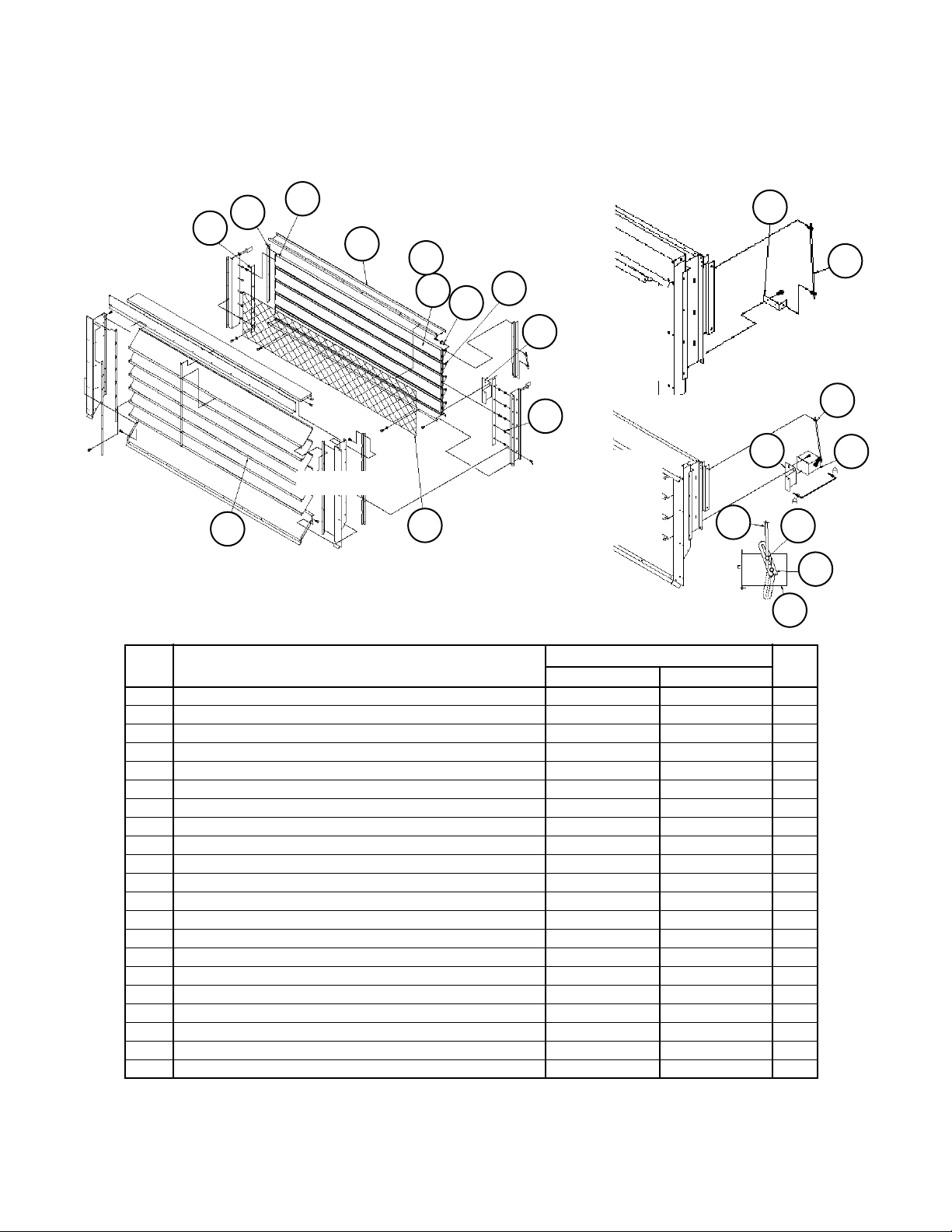
Section A- Outdoor/Return Air Section
0 - 30% Outside Air Section w/ ACT3
C20= BE or BY and C19= BE, BY, or HY
11
26
14
30
9
Damper Detail
10
12
13
15
33
31
13
Linkage
Detail:
Without
Actuator
C20= BY
8
34
32
Linkage
Detail:
With
Actuator
C20= BE
15
13
34
35
36
View A-A
35
Ref. Part Actuator Qty.
No. Description C20= BE C20= BY,HY
Damper Assembly- Complete 1 055608703 055608702 1
Damper Assembly
2
098314001 098314001 1
8 Blade- Damper 044193212 044193212 5
9 Gasket- Vinyl 055940203 055940203 1
10 Gasket- Vinyl 044193124 044193124 5
11 Seal- End 055942501 055942501 2
12 Grille 055942601 055942601 1
13 Support- Motor 055595701 1
Rod- Support Angle 055608601 1
14 Bar- Linkage 055942701 055942701 2
15 Shaft- Linkage 055536608 055536608 1
26 Louver 055593202 055593202 6
30 Plug- End 041003505 041003505 5
31 Plug- End 041003506 041003506 5
32 Bushing- Damper Blade 043730400 043730400 10
33 Bushing- Linkage Bar, Nylon 046098300 046098300 10
34 Ball Joint- Damper 000887000 not used 2
35 Actuator- Motorized, 120V ACT3 059999804 not used 1
36 Crank Arm- Damper 032279200 not used 1
N/S Isolation Damper C19= BE only 3 055942906 055942906 1
N/S= Not Shown on Diagram.
1
Complete assy includes the damper assy and linkage (no actuator) or actuator assy.
2
Damper only, no linkage or actuator components.
3
Details follow exhaust damper section.
RoofPak Singlezone; RCS,RDT,RFS,RPS 080-135 “C” Rev. AD 07/12 RPL 700007000 / Page 24
Page 25
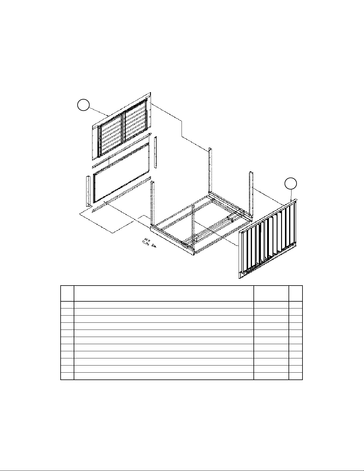
Section A- Outdoor/Return Air Section
0- 100% Economizer Section with Barometric Exhaust Damper
Units without Return Air Fans
C20= DE, DY, EE, EY, FE, FY, GE, or GY, C21= YYYY
12
Back Return (C19= HY) shown.
11
Ref Part Part Qty.
No. Description Number
11 Economizer Damper 1
w/Act.(C20= DE, EE, FE, GE) 055941103 1
w/o Act. (C20= DY, EY, FY, GY) 055941102 1
12 Exhaust Damper Assy 2 until 1/05
Powered (C20= EE, EY, GE, GY) 055929902 1
Barometric (C20= DE, DY, FE, FY) 055929901 1
Exhaust Damper Assy 1/05 & later
Powered (C20= EE, EY, GE, GY) 112040401 1
Barometric (C20= DE, DY, FE, FY) 112039601 1
N/S Isolation Damper C19= BE only 3 055942906 1
N/S= Not Shown on diagram.
1
Economizer with actuator (C20= DE, FE, GE, HE) requires MicroTech Controls. Without actuator (C20= DY, FY,
GY, HY), requires controls by others (C12= YM, YC). Economizer detail two pages after next.
2
Powered Exhaust Damper (until 1/05) detail follows the Economizer Damper detail.
3
Details follow exhaust damper section.
RoofPak Singlezone; RCS,RDT,RFS,RPS 080-135 “C” Rev. AD 07/12 RPL 700007000 / Page 25
Page 26
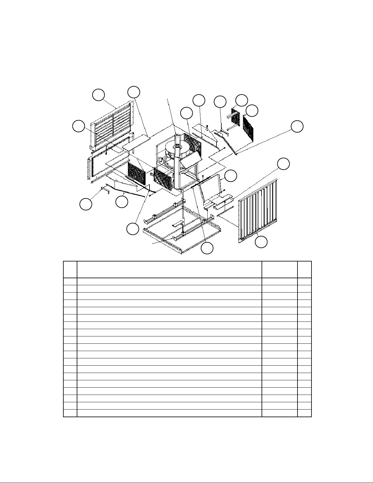
Section A- Outdoor/Return Air Section
0- 100% Economizer Section with Barometric Exhaust Damper
Units with 44” Return Air Fans
C20= DE, DY, EE, EY, FE, FY, GE, or GY C21= 44B* or 44W*
12
124
57
(see Return Fan Detail)
54
16
16
(see Return
Fan Detail)
124
16
16
57
126
125
54
Bottom Return
(C19= BY, BE, BD,
BE) shown.
56
55
11
Ref Part Part Qty.
No. Description Number
11 Economizer Damper 1
w/Actuator C20= DE, EE, FE, GE 055941103 1
w/o Actuator C20= DY, EY, FY, GY 055941102 1
12 Exhaust Damper Assy 2 until 1/05
Powered C20= EE, EY, GE, GY 055929902 1
Barometric C20= DE, DY, FE, FY 055929901 1
Exhaust Damper Assy 1/05 & later
Powered C20= EE, EY, GE, GY 112040401 1
Barometric C20= DE, DY, FE, FY 112039601 1
N/S Isolation Damper C19= BE only 3 055942906 1
16 Gasket .125 x 2.00 055582601 20
54 Gasket 055921404 2
55 Gasket 055921415 2
56 Gasket 055921406 2
57 Gasket 055921407 2
124 Fan Guard 055957610 3
125 Fan Guard 055957611 1
126 Fan Guard 055957612 1
N/S= Not Shown on diagram.
1
Economizer with actuator (C20= DE, FE, GE, HE) requires MicroTech Controls. Without actuator (C20= DY, FY,
GY, HY), requires controls by others (C12= YM, YC). Economizer detail on page after next.
2
Powered Exhaust Damper (until 1/05) detail follows the Economizer Damper detail.
3
Details follow exhaust damper section.
RoofPak Singlezone; RCS,RDT,RFS,RPS 080-135 “C” Rev. AD 07/12 RPL 700007000 / Page 26
Page 27
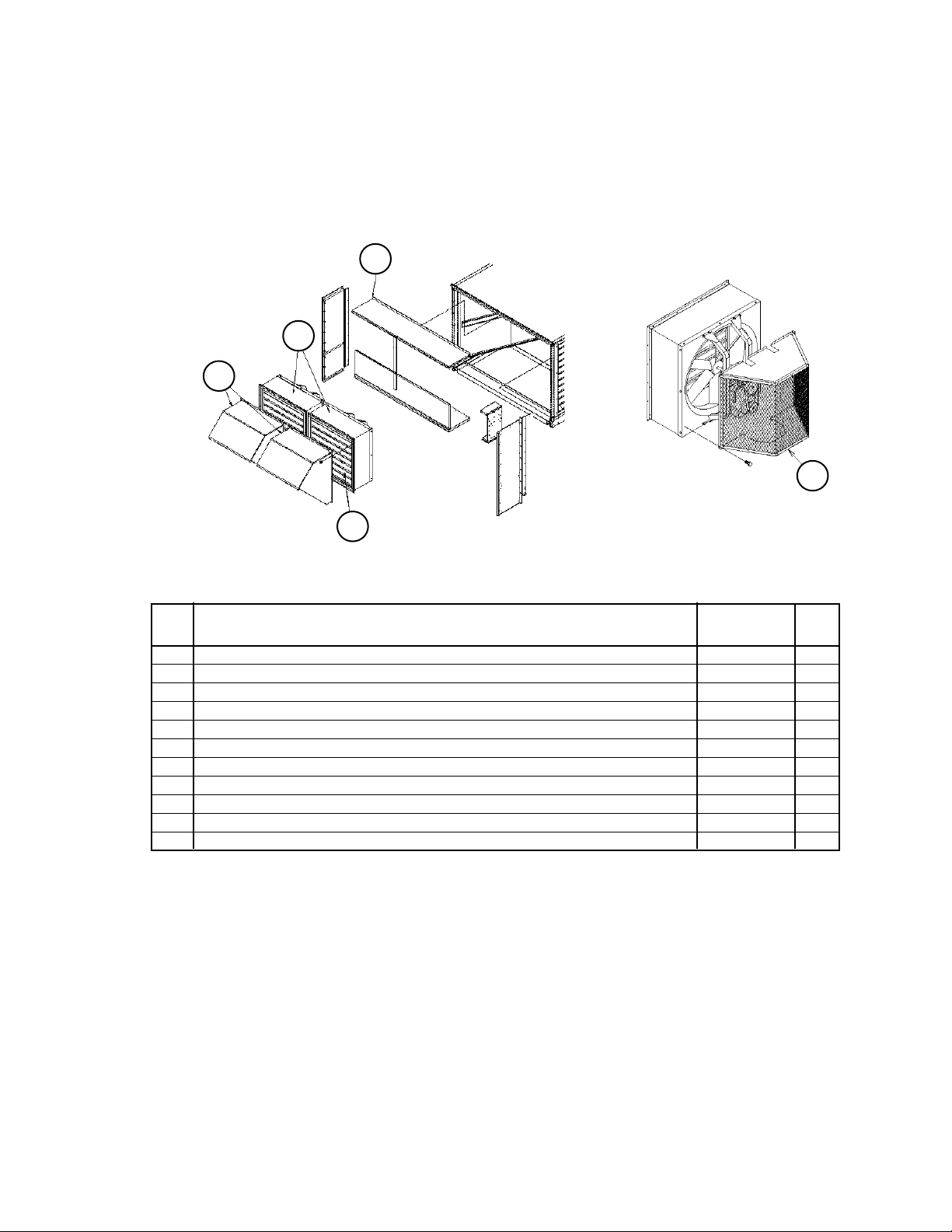
Section A- Outdoor/Return Air Section
0- 100% Economizer Section with Prop Exhaust Fan & Damper
C20= HE, HY, JE or JY, C24= 2 or 3
Section Assembly Detail
-2 Fan Arrangement Shown(C24= 2)
6
41
Ref. Part Part Qty.*
No. Description Number
N/S Isolation Damper w/ actuator C19= BE only 1 055942906 1
N/S Economizer Damper
w/Act.(C20= HE, JE) 055941103 1
w/o Act. (C20= HY, JY) 055941102 1
20
Fan Guard
15
6
2
6 Fan Assembly 3 208/230/460V 111056601
Fan Assembly 3 575V 111056602
15 Fan Guard 111181901 1
20 Panel- Weather Hood 111173101 1
41 Hood- Prop Exhaust 111182301 1
Grille Only- Prop Exhaust Hood 111182101 1
N/S= Not Shown on diagram.
* Quantity is PER fan. Quantity per unit doubles when 2 prop fans are in place (Code 24= 2).
1
See detail following Exhaust Damper Detail.
2
Economizer with actuator (C20= DE, FE, GE, HE) requires MicroTech Controls. Without actuator (C20= DY, FY, GY, HY),
requires controls by others (C12= YM, YC). Economizer detail two pages after next.
3
See detail following Isolation Damper Detail.
4
Quantity may be two (Code 24= 2) or three (C24= 3).
5
Quantity is PER fan.
4
4
5
5
5
5
RoofPak Singlezone; RCS,RDT,RFS,RPS 080-135 “C” Rev. AD 07/12 RPL 700007000 / Page 27
Page 28
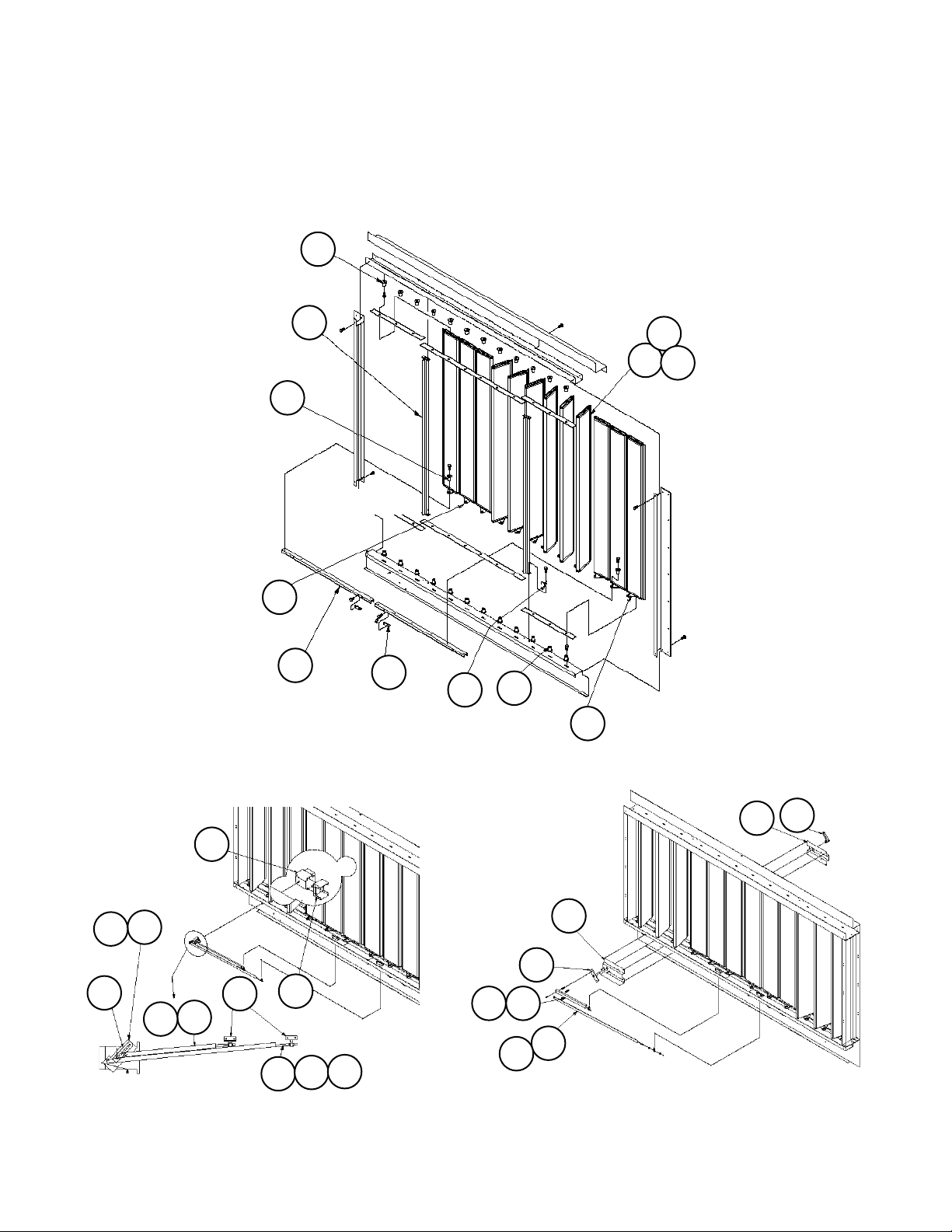
Section A- Outdoor/Return Air Section
0 - 100% Economizer Damper Detail
C20= DE, DY, EE, EY, FE, FY, GE, GY, HE, HY, JE, JY
Diagrams
24
26
23
Damper Detail
28
18
19
16
24
29
13
27
25
Linkage
Detail:
With
Actuator
C20= *E
7
21
20
21
RoofPak Singlezone; RCS,RDT,RFS,RPS 080-135 “C” Rev. AD 07/12 RPL 700007000 / Page 28
6
22
Detail
19
17
40
21
4
* D, E, F, G, H, J
21
7
21
Linkage
Detail:
Without
Actuator
C20= *Y
17
5
6
11
20
Page 29
Section A- Outdoor/Return Air Section
0 - 100% Economizer Damper w/ ACT3
C20= DE, DY, EE, EY, FE, FY, GE, GY, HE, HY, JE, JY
Components
Ref. Part Actuator Qty.
No. Description C20= *E C20= *Y
Damper Assy- Complete 1 055941103 055941102 1
Damper Assembly 2 098313301 098313301 1
4 Shaft Assembly 058390001 not used 1
5 Shaft Assembly not used 056081001 1
6 Plate- Crank Arm 055542001 1
Shaft Assembly 055536603 1
7 Shaft- Linkage 058389901 058389901 1
11 Channel- Support until 4/01 not used 056080601 1
Channel- Support 4/01 & later not used 111087501 1
13 Blade- Damper 044195103 044195103 12
16 Stop/Anti-Rotate- Damper 065779801 065779801 4
17 Support- Damper Motor 055546601 1
Channel- Support until 4/01 056264501 1
Channel- Support 4/01 & later 111087502 1
18 Bar- Linkage 044194800 044194800 2
19 Drive Tab- Linkage Bar 044194900 044194900 2
20 Crank Arm- Damper 032279200 1
Crank Arm- Adjustable 025072600 1
21 Ball Joint- Damper 000887000 000887000 4
22 Actuator- ACT3 until 10/98 047936105 not used 1
Actuator- ACT3 10/98 & later 059999804 not used 1
23 Bushing- Linkage Bar 046098300 046098300 12
24 Bushing- Damper Blade 043730400 043730400 24
25 Gasket- Vinyl 044193116 044193116 12
26 Gasket- Vinyl 045655716 045655716 2
27 End Plug- Damper 041003501 041003501 12
28 End Plug- Damper 041003502 041003502 6
29 End Plug- Damper 041003503 041003503 6
40 Bearing- Sleeve until 4/01 not used 047138504 2
N/S Gasket- Neoprene 3 056003501 056003501 4
N/S= Not Shown on Diagram.
1
Complete assy includes the damper assy and linkage (no actuator) or actuator assy.
2
Damper only, no linkage or actuator components.
3
Applied from outer edge of assembly to inside edge of center support and flush with edge of the bottom channel.
RoofPak Singlezone; RCS,RDT,RFS,RPS 080-135 “C” Rev. AD 07/12 RPL 700007000 / Page 29
Page 30
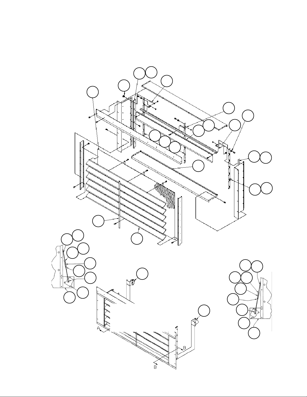
Section A- Outdoor/Return Air Section
0 - 100% Economizer Exhaust Damper (until 1/05)
C20= DE, DY, EE, EY, FE, FY, GE, GY w/ACT10, ACT11
Diagrams
39
17
Damper Detail
32
23
25
19
35
View A-A
ACT11
Detail
44
43
41
33
34
42
21
18
14
36
15
ACT11
34
43
13
38
40
View B-B
ACT10
Detail
25
43
44
34
16
34
39
43
41
36
20
Powered Closure Exhaust
Damper Actuator Detail
(ACT10, ACT11 )
C20= EE, EY, GE, GY
RoofPak Singlezone; RCS,RDT,RFS,RPS 080-135 “C” Rev. AD 07/12 RPL 700007000 / Page 30
37
ACT10
42
33
21
37
20
Page 31

Section A- Outdoor/Return Air Section
0 - 100% Economizer Exhaust Damper Detail (until 1/05)
C20= DE, DY, EE, EY, FE, FY, GE, GY
Components
Ref. Part Damper Type
No. Description Powered Barometric Qty.
C20= E*, G* C20= D*, F*
Exhaust Damper Assy 055929902 055929901 1
13 Blade- Exhaust 055925201 055925201 7
14 Louver- Exhaust 055925602 055925602 6
15 Plate- Linkage 055925801 055925801 3
16 Angle- Blade Support 055925301 055925301 1
17 Angle- Blade Support 055925302 055925302 1
18 Strap- Louver 055925703 055925703 1
19 Support- Damper Blade 055549001 055549001 21
20 Panel- Motor Mount until 2/02 055928402 not used 2
Panel- Motor Mount 2/02 & later 111263001 not used 2
21 Plate- Linkage until 2/02 055928501 not used 2
Plate- Linkage 2/02 & later 111263101 not used 2
Ratchet Pin 2/02 & later 111059301 not used 2
23 Grille- Exhaust Damper 055925502 055925502 1
25 Shaft- Damper Blade 055924402 055924402 14
32 Bearing- Flange, Nylon 001113500 001113500 14
33 Fastener- Stud 018619100 not used 2
34 Ball Joint- Damper 000887000 000887000 2
35 Bearing- Sleeve 047138507 047138507 21
36 Actuator- Motorized, Opposite Drive Side ACT11
Until 2/02 049126401 not used 2
2/02 & later 111059101 not used 2
37 Actuator- Motorized, Drive Side ACT10
Until 2/02 049126401 not used 2
2/02 & later 111059101 not used 2
38 Gasket- Vinyl 044193124 044193124 1
39 Gasket- Sponge Rubber 021768949 021768949 2
40 Gasket- Vinyl 055940201 055940201 5
41 Cap- Closure 049025401 not used 2
42 Spring- Compression 065497401 not used 2
43 Bearing- Sleeve 047138510 not used 2
44 Rod- Linkage 056225101 not used 2
* E (powered) or Y (manual).
RoofPak Singlezone; RCS,RDT,RFS,RPS 080-135 “C” Rev. AD 07/12 RPL 700007000 / Page 31
Page 32

Section A- Outdoor/Return Air Section
Return Air Plenum Isolation Damper w/ Actuator ACT6
C19= BE
Damper Detail
16
15
23
20
3
22
424
19
17
18
22
15
ACT6 Motorized Actuator
20
22
View A-A
21
Ref. Part Part Qty.
No. Description Number
Isolation Damper Assy- Motorized 055921126 1
3 Motor Mount Assembly 055921201 1
4 Blade Assembly- Return, 4” 055921302 15
15 Angle- Linkage 055917902 3
16 Angle- Blade 055638101 45
17 Shaft- Damper Blade 055637801 30
18 Shaft- Linkage 055536601 1
19 Bearing- Flange, Nylon 001113500 30
20 Actuator- Motorized- SPDT ACT6 059999804 1
21 Crank Arm- Damper 032279200 1
22 Ball Joint 000887000 2
23 Bearing- Sleeve 047138507 45
24 Gasket- Vinyl 030051985 16
RoofPak Singlezone; RCS,RDT,RFS,RPS 080-135 “C” Rev. AD 07/12 RPL 700007000 / Page 32
Page 33

Section A- Outdoor/Return Air Section
Prop Exhaust Fan & Damper
C20= HE, HY, JE or JY, C24= 2 or 3
6
Fan Assembly Components
- 2 Fan Arrangement ShownCode 24= 2
54
51
1B
1A
6C
6B
6E
6D
6F
6G
1
6H
Lube Line Detail
6A
Ref. Sch. Part Part
No. Sym. Description Number
1 AFD20 Inverter see charts below
1A Resistor- Inverter 044690105 1 1 1 1
1B Jumper- Inverter
6 Fan Assembly- Complete 111056601
Fan Assembly- Complete 111056602
6A Damper- Backdraft
6B Fan Prop- 36” 300044027 14 14 14 1
6C Fan Shaft 300044028 14 14 14 1
6D Bearing 300044029 24 24 24 2
6E Fan Sheave 019291400 14 14 14 1
6F Bushing- Fan Sheave 000804000 14 14 14 1
6G Belt 049260805 24 24 24 2
6H Motor Sheave 000607600 14 14 14 1
6I Motor 300046887 14 14 1
Motor 300046251 1
51 Tube- Plastic 2 020954800 8’ 8’ 8’ 8’
53 Coupling- Tube
54 Fitting- Grease
1
Quantity= 2 when Inverter model 3500 (Code 15= G) is used.
2
Quantity shown are for 2 fans. Quantities for 3 fan units: Ref. 51= 32’; Ref. 53= 6; Ref. 54= 6.
3
Contact Daikin McQuay Parts.
4
Quantity is PER fan.
Inverter- 2 Fan Units (Code 24= 2)
53
(see following page
Voltage
Control Box
208V
230V
1
055719731 3 3 3 3
3
2
.25 x .125 FPT 021213800 2 2 2 2
2
000109800 2 2 2 2
Inverter- 3 Fan Units (Code 24= 3)
460V
4
6I
575V
4
4
4
4
4
4
4
4
Voltage
Code Inverter Model Part
208V
230V
15= Number
460V
A 401 until 10/04 060011617 1 1
401 until 10/04 060011604 1
550 10/04 & later 112046017 1 1
550 10/04 & later 112046004 1
G 3500 098656918 1
3500 098656928 1
3500 098656905 1
R VTAC9 111046870 1 1
VTAC9 111046856 1
S MD2 349956611 1 1
MD2 349956627 1
Voltage
Code Inverter Model Part
575V
15= Number
A 401 until 10/04 060011618 1 1
401 until 10/04 060011605 1
550 10/04 & later 112046018 1 1
550 10/04 & later 112046005 1
G 3500 098656919 1
3500 098656929 1
3500 098656906 1
3500 098656946 1
R VTAC9 111046871 1 1
VTAC9 111046857 1
S MD2 349956612 1 1
208V
230V
460V
MD2 349956628 1
RoofPak Singlezone; RCS,RDT,RFS,RPS 080-135 “C” Rev. AD 07/12 RPL 700007000 / Page 33
575V
Page 34

Section A- Outdoor/Return Air Section
120
131
2 Fan Units Shown
Prop Exhaust Fan Inverter and Control Box
Until 3/05
Voltage
Ref. Sch. Part Part
No. Sym. Description Number
120 PB20 Power Block 030372705 1 1 1 1
131 M51,52,53 Contactor 027514101 1 1 1 1
135 136
135 OL51,52,53 Overload 059990101 1 1 1 1
136 Heater- Overload 059990611 3 3
Heater- Overload 059990609 3 3
NOTE: All quantities listed are PER fan.
3/05 & to 10/06**
208V
230V
460V
575V
142
OL51
M51 M52
2 Fan Units
Shown
140
OL52
141
MMP51,
MMP52 or
220
2 Fan Units
Shown
MMP53
Detail
Contactors &
Overloads
Detail
Voltage
Ref. Sch. Part Part
208V
230V
460V
No. Sym. Description Number
575V
140 MMP
51,52,53 MMP- Prop Exh. Motors 349934012 1 1
MMP- Prop Exh. Motors 349934010 1
MMP- Prop Exh. Motors 349934009 1
141 Line Shield 349933001 1 1 1 1
142 Short Circuit Alarm 349933903 1 1 1 1
NOTE: All quantities listed are PER fan.
10/06 to present**
Voltage
Ref. Sch. Part Part
208V
230V
460V
No. Sym. Description Number
220 OL51,52,53 Overload 349934663 1
Overload 349934662 1
Overload 349934660 1
Overload 349934659 1
230 M51,52,53 Contactor 349932123 1 1
Contactor 349932121 1 1
NOTE: All quantities listed are PER fan.
575V
** Units built between 10/06 and 12/06 may have either group of
components installed. If unsure, contact Daikin McQuay Parts to
230
RoofPak Singlezone; RCS,RDT,RFS,RPS 080-135 “C” Rev. AD 07/12 RPL 700007000 / Page 34
verify.
Page 35
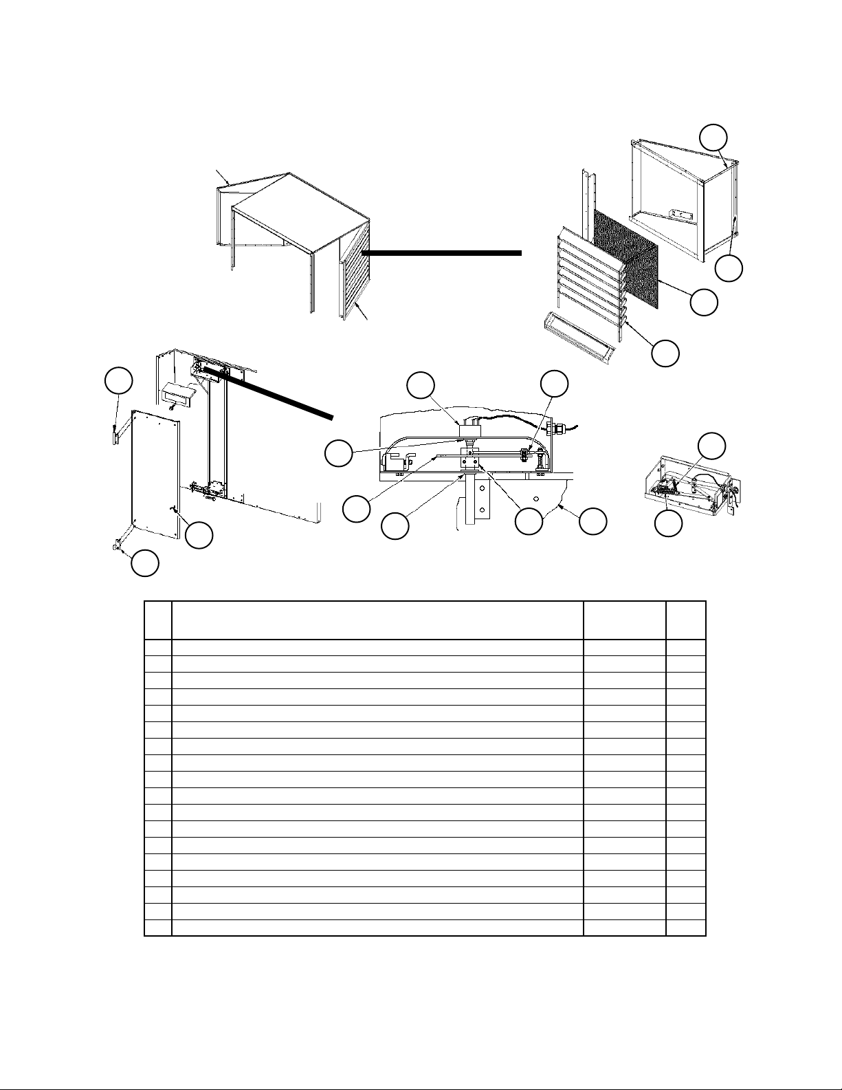
Section A- Outdoor/Return Air Section
LH Louvered Door Assy
Section Final
Assembly
Design Flow
Code 20= FE, FY, GE, GY
Louvered Door
Assembly Detail
RH Louvered Door Assy
4
➤
3
2
1
105
9
127
➤
12
110
104
106
Design Flow Vane and
Vane Bearings Detail
Ref Part Part Qty.
No. Description Number
1 Louver Panel Left Hand Door 059595204 15
Louver Panel Right Hand Door 059595203 15
2 Grille 055541401 2
3 Gasket 055921403 1
4 Gasket 055921401 1
9 Potentiometer 098663701 1
12 O’Ring- Potentiometer 098663801 1
104 Panel- Vane 098661803 1
105 Shaft- Upper 098662601 1
106 Bearing- Lower 091634501 1
109 Crank Arm Assy Left Hand Door 091658802 1
Crank Arm Assy Right Hand Door 091658801 1
110 Link Arm
120 Bearing 060014201 1
127 Bearing 047138535 1
130 Spring- Main 098664701 1
131 Spring- Secondary 098664901 1
N/S Leveling Kit- Design Flow 091659301 1
N/S= Not shown on diagram.
1
Quantity is PER door.
2
P/N is unit specific. Contact Daikin McQuay Parts with overall length and bolt hole spacing so that the correct part
can be identified.
120
Adjuster Control Assy
Detail
109 104
130
2
1
131
Spring
Detail
1
RoofPak Singlezone; RCS,RDT,RFS,RPS 080-135 “C” Rev. AD 07/12 RPL 700007000 / Page 35
Page 36

Section A- Outdoor/Return Air Section
Return Air Fan- Fan Mounts
Until 11/04
Mounting
162
164
Diagram
163
161
or
or
63
61
62
64
or
or
93
89
90
190
92
91
Rubber Mounts
188
189
123
155
156
Spring Mounts
91
61 62
121
122
160
161 162
163
63
164
21
64
Rubber Mounts (Code 15= 44B1 or 44W1)
Ref. Fan Motor Part Part Qty.
No. HP Description Number
21 All Channel- Mount Support 055512101 4
61 5 - 40 Rubber Mount- Red 021639701 1
50, 60 Rubber Mount- Black 021639704 1
62 5 - 40 Rubber Mount- Red 021639701 1
50, 60 Rubber Mount- Black 021639704 1
63 All Rubber Mount- Red 021639701 1
64 All Rubber Mount- Red 021639701 1
89 All Screw- Cap, 3/8-16 X 1” 048878118 8
90 All Washer- Lock, 3/8” 048164812 8
91 All Nut- 1/2-13 032333305 12
92 All Screw- Cap, 1/2-13 X 1” 040499501 8
93 All Washer- Plain, 1/2” 040500310 8
Spring Mounts (Code 15= 44B2, 44B3, 44W2 or 44W3)
Ref. Fan Motor Part Part Qty.
No. HP Description Number
121 All Support Assembly 055606901 4
122 All Screw Adjust Assembly 055528201 4
123 All Channel Assembly 055606801 4
155 All Plate- Gasket Retainer 055502101 4
156 All Support- Spring Locator 055502201 4
160 All Pad- Rubber Vibration 048447901 4
161 5 - 30 Mount- Spring, Red 048448503 1
40 - 60 Mount- Spring, Green 048448504 1
162 5 - 30 Mount- Spring, Red 048448503 1
40 - 60 Mount- Spring, Green 048448504 1
163 All Mount- Spring, Red 048448503 1
164 All Mount- Spring, Red 048448503 1
188 All Nut- 5/8-11 040500002 4
189 All Screw- Cap, 3/8-16 X 1” 048878118 12
190 All Washer- Lock, 3/8” 048164812 8
N/S All Screw- Tapping, 1/4-20 046093809 8
RoofPak Singlezone; RCS,RDT,RFS,RPS 080-135 “C” Rev. AD 07/12 RPL 700007000 / Page 36
Page 37

Section A- Outdoor/Return Air Section
Return Air Fan- Fan Mounts
11/04 & Later
163
92
93
89
81
Rubber Mounts
161
or
61
63
or
188
189
181
Spring Mounts
91
or
164
121
161 162
163
91
61 62
63
21
162
or
62
64
164
Rubber Mounts (Code 15= 44B1 or 44W1)
Ref. Fan Motor Part Part Qty.
No. HP Description Number
21 All Channel- Mount Support 055512101 4
61 5 - 40 Rubber Mount- Red 021639701 1
64
50, 60 Rubber Mount- Black 021639704 1
62 5 - 40 Rubber Mount- Red 021639701 1
50, 60 Rubber Mount- Black 021639704 1
63 All Rubber Mount- Red 021639701 1
64 All Rubber Mount- Red 021639701 1
81 All Nut 059992201 8
89 All Screw 112047201 8
91 All Nut- 1/2-13 032333305 12
92 All Screw- Cap, 1/2-13 X 1” 040499501 8
93 All Washer- Plain, 1/2” 040500310 8
Mounting
Diagram
Spring Mounts (Code 15= 44*2) & Seismic Spring (44*3)
Ref. Fan Motor Part Part Qty.
No. HP Description Number
121 All Mount
Spring (C15= 40*2) 251783201 4
Seismic (C15= 40*3) 251783301 4
161 5 - 10 Spring Mount- Brown 251784801 1
15 - 30 Spring Mount- Red 251784901 1
40 - 60 Spring Mount- Red/Black 251785001 1
162 5 - 10 Spring Mount- Brown 251784801 1
15 - 60 Spring Mount- Red 251784901 1
163 5 - 10 Spring Mount- Brown 251784801 1
15 - 30 Spring Mount- Red 251784901 1
40 - 60 Spring Mount- Red/Black 251785001 1
164 5 - 10 Spring Mount- Brown 251784801 1
15 - 60 Spring Mount- Red 251784901 1
181 All Nut
Spring (C15= 40*2) 059992201 12
Seismic (C15= 40*3) 111056301 20
188 All Nut 040500002 4
189 All Screw
Spring (C15= 40*2) 112047201 12
Seismic (C15= 40*3) 112047201 20
RoofPak Singlezone; RCS,RDT,RFS,RPS 080-135 “C” Rev. AD 07/12 RPL 700007000 / Page 37
Page 38

Section A- Outdoor/Return Air Section
Return Air Fan (Code 21-= 44B* or 44W*)
18
35
17
23
24
36
11
19
21
27
26
37
1
4
13
12
Ref. Motor Part No VIV With VIV
No. HP Description C21= 44B* C21= 44W* Qty.
1 Motor see following page
4 All Mount- Motor 056234101 056234101 1
5 All Channel Assembly 056234201 056234201 1
11 All Clamp- Motor Channel until 11/02 056230201 056230201 1
All Clamp- Motor Channel 11/02 & later 056230203 056230203 1
12 All Clamp- Motor Channel until 11/02 056230202 056230202 1
All Clamp- Motor Channel 11/02 & later 056230203 056230203 1
13 All Shaft- Fan 2.438” dia. 056255103 056255103 1
14 All Linkage- Shaft not used 055536608 2
17 All Tubing- Plastic 021136745 021136745 2
18 All Coupling until 12/04 021213700 021213700 2
All Coupling 12/04 & later 027674000 027674000 2
19 All Coupling 021213800 021213800 2
21 All Fitting- Grease 1/8” MPS 000109800 000109800 2
23 All Bearing- 2.437” Opposite Drive End 020649905 020649905 1
24 All Bearing- 2.437” Drive End 049547014 049547014 1
26 All Key- Wheel 5/8” X 6½” 023221610 023221610 1
27 All Key- Fan Sheave 5/8” x 5½” 023221607 023221607 1
28 5- 20 Actuator ACT2 not used 059999801 1
25- 60 Actuator ACT2 not used 059999802 1
29 All Crank Arm- Damper not used 032279200 1
30 All Ball Joint not used 000887000 2
35 All Wheel- SISW until 6/00 093413720 093413720 1
All Wheel- SISW 6/00 & later 111041201 111041201 1
36 All Control- Fan Vane until 6/00 not used 048447007 1
All Control- Fan Vane 6/00 & later not used 110941910 1
36 All Funnel- Inlet until 6/00 092045214 not used 1
All Funnel- Inlet 6/00 & later 110941810 not used 1
37 All Lock Collar 2.437” 049115912 049115912 1
48 All Lock Washer 048164814 048164814 2
63 All Cap Screw 040499501 040499501 2
* Mounting type 1= RIS, 2= Spring, 3= Spring w/ seismic snubbers.
48
63
5
28
14
29
30
RoofPak Singlezone; RCS,RDT,RFS,RPS 080-135 “C” Rev. AD 07/12 RPL 700007000 / Page 38
Page 39

Section A- Outdoor/Return Air Section
Return Air Fan Motors
All motors listed below are Across-The-Line start (C10= AL or PW). There are some units that have Part-Winding start motors (C10= PP or PS).
These units have motors 15HP and greater and are 208V or 230V only. Contact Daikin McQuay Parts if a PW replacement motor is needed.
H.P. Unit ODP ODP HiEff ODP PrEff. TEFC TEFC HiEff TEFC PrEff
Voltage C22= *AY C22= *EY C22= *JY C22= *GY C22= *HY C22= *KY
C09= 12
5 208/60/3 020521000 039447600 065817200 025435800 049186800 065819500
7.5 208/60/3 020524800 037530300 065817300 024581000 047665900 065819600
10 208/60/3 021486000 038999000 065817400 025436900 047666100 065819700
15 208/60/3 049100600 039896200 049100700 049186900 065817500 065819800
20 208/60/3 049101200 039895800 049101300 049187000 065817600 065819900
25 208/60/3 034243300 039448900 049100900 049187100 065817700 065820000
30 208/60/3 049101500 041775200 205066500 049101600 049187200 205066800
40 208/60/3 030389500 041775300 205067100 049101900 049187300 205070700
50 208/60/3 049102200 041775400 205067500 049102300 049187400 205091600
60 208/60/3 049102600 041775800 205067700 048443300 049187500
C09= 29
5 230/60/3 019664800 039442500 065818200 020520600 040161200 065820200
7.5 230/60/3 019855100 039448700 065818300 020522100 049100500 065820300
10 230/60/3 017859600 039446500 065818400 024211500 044691100 065820400
15 230/60/3 023256100 039446600 026215800 038689700 065818500 065820500
20 230/60/3 022772100 039448800 031314500 040161300 065818600 065820600
25 230/60/3 029863500 039896100 032242500 040161400 065818700 065820700
30 230/60/3 040626800 040626800 205066600 032243100 049025300 205067000
40 230/60/3 041770000 041770000 205067200 048448000 048448000 205067200
50 230/60/3 039899200 039899200 205067600 040161600 040161600 205069400
60 230/60/3 041775500 041775500 065819100 046748300 046748300 205069600
C09= 27
5 460/60/3 019664800 039442500 065818200 020520600 040161200 065820200
7.5 460/60/3 019855100 039448700 065818300 020522100 049100500 065820300
10 460/60/3 017859600 039446500 065818400 024211500 044691100 065820400
15 460/60/3 023256100 039446600 026215800 038689700 065818500 065820500
20 460/60/3 022772100 039448800 031314500 040161300 065818600 065820600
25 460/60/3 029863500 039896100 032242500 040161400 065818700 065820700
30 460/60/3 040626800 040626800 205066600 032243100 049025300 205067000
40 460/60/3 041770000 041770000 205067200 0484480000 048448000 205067200
50 460/60/3 039899200 039899200 205067600 040161600 040161600 205069400
60 460/60/3 041775500 041775500 065819100 046748300 046748300 205069600
C09= 37
5 575/60/3 046741800 046741900 205168900 048169900 049188400 046514600
7.5 575/60/3 046744400 047443300 205168800 040160100 049188500 046514700
10 575/60/3 031326700 047443400 205168600 049763700 049188600 065821400
15 575/60/3 046744500 047443500 046749000 049185200 205166600 065821500
20 575/60/3 046744600 049181100 049186200 049188700 205166800 065821600
25 575/60/3 047133700 049181200 049186300 049188800 205166900 065821700
30 575/60/3 047137600 049181300 205066700 049126100 049188900 205067000
40 575/60/3 047138000 049181400 205067300 049186400 049189000 205067300
50 575/60/3 047133800 049181500 205091800 049126200 049189100 205069500
60 575/60/3 046747600 049181600 205069000 049186500 049189200 205069800
RoofPak Singlezone; RCS,RDT,RFS,RPS 080-135 “C” Rev. AD 07/12 RPL 700007000 / Page 39
Page 40

Section A- Outdoor/Return Air Section
Section Mounted Controls
OAE, RAE, RAT, SD2, LT11, S11, REC11
Bottom Return
Shown
C19= BY or BE
Economizer
43
Economizer
40
40
41
OAE- Mechanical Enthalpy (Code 17= Y*)
Ref Part Part
No. Description Number Qty.
40 Mount- OAE Enthalpy 055800101 1
41
41 Enthalpy Assembly
(knob & Control) 055740691 1
Knob only 026215500 1
Control OAE only 030706702 1
40
OAE & RAE Differential Enthalpy (Code 17= C*)
Ref Part Part
No. Description Number Qty.
Mixing Box
40 Mount- OAE Enthalpy
Economizer Units 059328901 1
Mixing Box Units 055800301
41 Control- OAE 049262201 1
43 Control- RAE 049262202 1
43
RAT- Outdoor Air Temperature Sensor
Ref Part Part
No. Description Number Qty.
7 Return Air Temp.
Sensor- RAT 1934146011 1
1
7
P/N is for MicroTech III Controls. For Original MicroTech controls
(C12= 1,2,3,4,5) use p/n 065829505. For MicroTech II controls
(C12= _D or _S) use p/n 060004705.
30
30
SD2- Return Air Smoke Detector
C16= 1 or 3
Ref Part Part
No. Description Number Qty.
Return Air Opening
Return Air
Opening
30 Smoke Detector SD2
until 2/00 055744901 1 1
2/00- 2/03 060016501 1
Back Return
C19= HY
Bottom Return
C19= BY or BE
2/03- Present 098873101 1
1
Includes Duct House 24- 240V p/n 049025003 + Smoke
Detector only p/n 049025004.
LT11- Return Fan Light/S11- Return Fan Light
Switch/ REC11- Return Fan Light Receptacle
84 85
88 89
RoofPak Singlezone; RCS,RDT,RFS,RPS 080-135 “C” Rev. AD 07/12 RPL 700007000 / Page 40
C49= E or F
Ref Part Part
No. Description Number Qty.
84 Light Fixture 042229500 1
85 Bulb- LT11 065492402 1
88 Light Switch- S11 065492201 1
89 Receptacle- REC11 030187000 1
Page 41

Section A- Outdoor/Return Air Section
Ebtron Sensor
Code 20= KE, KY, LE, LY, ME, MY
Ref. Part Part
No. Description Number Qty.
394 Ebtron Sensor 111055303 1 1
1
This is the standard Ebtron ‘Silver’ sensor. Some unit specials will use an
Ebtron “gold” sensor p/n 111055307.
394
RoofPak Singlezone; RCS,RDT,RFS,RPS 080-135 “C” Rev. AD 07/12 RPL 700007000 / Page 41
Page 42

Section B- Draw-Thru Filter/Blank Section
➩
Primary Codes that pertain: 25
Additional Codes that pertain: 06, 19, 20
Code 25 determines all of the section characteristics. If the first digit of Code 25= A,D or E the filters are in an angular
rack, if the first digit= F, G or H the filters are in a flat rack, if the first digit= S, T or V the filters are in a staggered rack,
if the first digit is L the filters are in a large staggered rack, and If the first digit= B or C there is a blank section. If the
second digit= Y there are no filters, if the second digit= A there are throwaway filters, if the second digit= B there are
30% eff. filters and if the second digit= C there are 30% eff. filters with antimicrobial Intersept. If the second digit=
D there are 65% eff. filters, if the second digit= E there are 95% eff. filters and if the second digit= G there are 95%
eff. filters with antimicrobial Intersept.
Code 06 determines the final assembly panel part numbers. For sheet metal components that make up the
Draw-Thru Filter/Blank Section, contact Daikin McQuay Parts to insure that correct liners, insulation and
hardware are ordered.
Codes 19 and 20 determine the Return Air section which has an effect on the final assembly panels.
This section pertains to the RPS, RFS, or RDT, but not the RCS.
Notes
71
70
Section B- Draw-Thru Filter/Blank Section
Section Mounted Controls
PC5- Clogged Filter Control and
SPS5- Clogged Filter Static Pressure Sensor
65
66
60
84 85
88 89
Controls PC5 and SPS5
Ref. Part Part Qty.
No. Description Number
60 Cover
65 PC5 Pressure Ctl 065493801 1
66 SPS5 Transducer
70 Plastic Tube 1 049095104 1
71 Grommet 1 004910100 1
1
Not used on units with MicroTech II or III.
1
055732501 1
1
049545005 1
LT13- Filter Section Light/S13- Filter Section
Light Switch/ REC13- Filter Section Receptacle
C49= E or F
Ref Part Part
No. Description Number Qty.
84 Light Fixture 055737501 1
85 Bulb- LT13 065492402 1
88 Light Switch- S13 065492201 1
89 Receptacle- REC13 030187000 1
RoofPak Singlezone; RCS,RDT,RFS,RPS 080-135 “C” Rev. AD 07/12 RPL 700007000 / Page 42
Page 43

Section B- Draw-Thru Filter/Blank Section
Filters
Angular Filter Rack- Code 25= AA, AB, AC, DB, DC, EB, EC
Air
Flow
4
14
14
Ref. Part Code Part Qty.
No. Description 25= Number
4 Filter- Throwaway 1 AA 000016100 33
Filter- 30% Eff. Throwaway 1 *B 031298002 33
4
4
Filter- 30% Eff w/Intersept 1 *C 111046306 33
5 Filter- Throwaway 2 AA 000011700 11
Filter- 30% Eff. Throwaway 2 *B 031298001 11
5
8
Filter- 30% Eff w/Intersept 2 *C 111046305 11
8 Stop, Filter 011484101 11
14 Angle Assembly 3 056077301 33
* First digit of code, may be A, D or E.
1
Filter size= 16 x 25 x 2.
2
Filter size= 16 x 20 x 2.
3
Optional- angle is mounted on leaving air side.
Flat Filter Rack- Code 25= FD, FE, FG, GD, GE, GG, HD, HE, HG
107A
106A
107
106
105A
105
104A
104
Ref. Part Code Part Qty.
No. Description 25= Number
104 Filter- 65% Eff. Cartridge 4 *D 065810704 12
Filter- 95% Eff Cartridge 4 *E 065810702 12
104A Gasket- Filter 021768924 12
105 Filter- 65% Eff. Cartridge 5 *D 065810703 4
Filter- 95% Eff Cartridge 5 *E 065810701 4
105A Gasket- Filter 021768912 4
106 Pre Filter 6 *D or *E
until 3/02 031298006 12
3/02 & later 111046101 12
106A Gasket- Pre Filter 111051900 24ft
107 Pre Filter 7 *D or *E
until 3/02 031298005 4
3/02 & later 111046103 4
107A Gasket- Pre Filter 111051900 8 ft
* First digit of code, may be F, G or H.
4
Filter size= 24 x 24 x 12. 5 Filter size= 12 x 24 x 12.
6
Filter size= 24 x 24 x 2.
7
Filter size= 12 x 24 x 2.
RoofPak Singlezone; RCS,RDT,RFS,RPS 080-135 “C” Rev. AD 07/12 RPL 700007000 / Page 43
Page 44

Section B- Draw-Thru Filter/Blank Section
Filters, Continued
Staggered Filter Rack- Code 25= SD, SE, SG, TD, TE, TG, VD, VE, VG
204A
204
Ref. Part Code Part Qty.
No. Description 25= Number
204 Filter- 65% Eff. Cartridge 4 *D 065810704 16
Filter- 95% Eff Cartridge 4 *E 065810702 16
204A Gasket- Filter 021768924 16
206 Pre Filter 5 *D or *E
until 3/02 031298006 16
3/02 & later 111046101 16
206A Gasket- Pre Filter 111051900 32ft
* First digit of code, may be S, T or V.
4
Filter size= 24 x 24 x 12.
5
206
206A
Large Staggered Filter Rack- Code 25= LD, LE, LG
204A
206A
206
204
207
204
207A
205
207
205A
204A
204
205A
205
207A
Filter size= 24 x 24 x 2.
Ref. Part Code Part Qty.
204A
No. Description 25= Number
204 Filter- 65% Eff. Cartridge 4 LD 065810704 16
Filter- 95% Eff Cartridge 4 LE 065810702 16
204A Gasket- Filter 021768924 16
205 Filter- 65% Eff. Cartridge 5 LD 065810703 8
Filter- 95% Eff Cartridge 5 LE 065810701 8
205A Gasket- Filter 021768912 8
206 Pre Filter 6 LD/LE
until 3/02 031298006 16
3/02 & later 111046101 16
206A Gasket- Pre Filter 111051900 32ft
207 Pre Filter 7 LD/LE
until 3/02 031298005 8
3/02 & later 111046103 8
207A Gasket- Pre Filter 111051900 16ft
4
Filter size= 24 x 24 x 12. 5 Filter size= 12 x 24 x 12.
6
Filter size= 24 x 24 x 2.
7
Filter size= 12 x 24 x 2.
Air Blender Section Parts
(C25= EE, EC, HD, HE, HG, VD, VE, VG)
Ref. Part Part Qty.
No. Description Number
65 Panel- Access 251802801 2
68 Air Blender 205139546 2
75 Plate- Economizer Linkage Access 059384601 1
75
68
RoofPak Singlezone; RCS,RDT,RFS,RPS 080-135 “C” Rev. AD 07/12 RPL 700007000 / Page 44
68
65
Page 45

Section C- Draw-Thru Blank Access Section
or Separate Inverter Section
Notes
➩
Primary Codes that pertain: 26, 14, 15
Additional Codes that pertain: 06
Code 26 determines if a section is installed and if so, the size of the section. If Code 26= S there is a 48” blank
section. If Code 26= Y, there is no section.
Code 06 determines the liners and insulation, and will affect the final assembly panels. For sheet metal components
that make up the Draw-Thru Access or Separate Inverter Section, contact Daikin McQuay Parts to insure
that correct liners, insulation and hardware are ordered.
Codes 14 & 15 determine if the unit has inverter(s) and if so where they are installed. If Code 14= 1, 2 or 4 AND Code
26= S, there is a separate inverter section. If Code 14= 3, 5, 6, 7, 8 or 9, the inverter(s) are installed in the Supply
Air Section. If Code 14= Y, there are no inverters. Code 15 determines the inverter type. The Inverter with Bypass
is shown below. All components pertaining to the Inverter are listed in the Supply Air Section (Section F).
This section pertains to the RPS, RFS or the RDT, but not the RCS.
Return Air Inverter
(AFD20)
Overload
(OL10- Supply
Air)
(OL20- Return
Air)
Power Block
(PB10- Supply Air)
(PB20- Return Air)
Supply Air Inverter
(AFD10)
Contactor
(M30A/M30B- Supply Air)
(M40A/M40B- Return Air)
Section C- Draw-Thru Blank Access Section
or Separate Inverter Section
Unit Mounted Controls- LT7, S17, & REC17
LT17- Filter Section Light/S17- Filter Section
84 85
88 89
Light Switch/ REC17- Filter Section Receptacle
Ref Part Part
No. Description Number Qty.
84 Light Fixture 042229500 1
85 Bulb- LT17 065492402 1
88 Light Switch- S17 065492201 1
89 Receptacle- REC17 030187000 1
RoofPak Singlezone; RCS,RDT,RFS,RPS 080-135 “C” Rev. AD 07/12 RPL 700007000 / Page 45
Page 46

Section D- Draw-Thru Cooling Section
Notes
➩
Primary Codes that pertain: 03, 27, 28
Additional Codes that pertain: 06
Code 03 determines the DX cooling coil size. if Code 03= S there is a small face area coil (24” section for unit sizes
080, 090 or 48” section for unit sizes 105- 115), and if Code 03= L it is a large face area coil (48” section for unit
sizes 080, 090 or 24/48” for unit sizes 105- 135).
Code 27 determines if there is a Section D. If Code 27= YYYY, then there is no section (for RPS or RFS units this
indicates that the cooling coil is in the Blow-Thru position, RDT units always have a section D). If the code is CYYY
or CYYS then there is a unit cooling coil and drain pan (the “S” means the drain pan is stainless steel, a “Y” in the
fourth position indicates that the pan is galvanized). If Code 27= DYYY or DYYS, then the section contains only a
drain pan (not an option for RDT units).
Code 28 will apply only if Code 27= CYYY or CYYS, and determines the coil characteristics.
Code 06 determines the liners and insulation, and will affect the final assembly panels. For sheet metal components
that make up the Draw-Thru Cooling Section, contact Daikin McQuay Parts to insure that correct liners,
insulation and hardware are ordered.
NOTE: The drawings and components listed in this section also apply to Section I—
Blow-Thru Cooling Section- RPS or RFS units.
RoofPak Singlezone; RCS,RDT,RFS,RPS 080-135 “C” Rev. AD 07/12 RPL 700007000 / Page 46
Page 47

Section D- Draw-Thru Cooling Section
Small Face DX Coils (Code 03= S, Unit Sizes 080, 090)
Small Face Area Coil
24” Section
Code 03= S
Unit Sizes 080, 090
3
Evaporator Coils, Drain Pans, Gasketing
Ref. Part Part Qty.
No. Description Number
3 Coil see page after next
10 Drain Pan Sloped
39
43
10
Galvanized C27= CYYY 056267751 1
Stainless C27= CYYS 056267752 1
Drain Pan Non- Sloped
Galvanized C27= CYYY 055531301 1
Stainless C27= CYYS 055531302 1
13 Pan- Auxiliary 9/93 & later
Galvanized C27= CYYY 055926503 1
13
Stainless C27= CYYS 057356801 1
Pan- Auxiliary Until 9/93 055524402 1
39 Gasket 049263200 8’
43 Gasket 021911422 2
1
Sloped drain pans are used 9/93 & later.
1
1
DX Evaporator Coils- Small Face (Code 03= S)
note: for units built 9/93 or earlier, 1/07 and later, or copper fin contact Daikin McQuay Parts.
Coil
Description
4Z 08 3 D
Fin Stock
D= AluminumLanced
C= Copper
H= Aluminum
Rows
3, 4, 5 ,6
Fins-per-inch
08, 10 ,12
Coil Model
Ref. Coil Description Unit Size Qty.
No. Code 28= 080, 090
3 Coil
4Z083D 068471567 1
4Z084D 068471468 1
4Z085D 068471568 1
4Z103D 068471736 1
4Z104D 068471529 1
4Z105D 068471471 1
4Z123D 068471545 1
4Z124D 068471458 1
4Z125D 068471459 1
5Z083H 068471079 1
5Z084H 068471143 1
5Z085H 068471226 1
5Z103H 068471347 1
5Z104H 068471192 1
5Z105H 068471254 1
5Z123H 068471255 1
5Z124H 068471358 1
5Z125H 068471122 1
RoofPak Singlezone; RCS,RDT,RFS,RPS 080-135 “C” Rev. AD 07/12 RPL 700007000 / Page 47
Page 48

Section D- Draw-Thru Cooling Section
Evaporator Coils, Drain Pans, Gasketing
Small Face DX Coils (Code 03= S, Unit Sizes 105, 115)
Small Face Area Coil
48” Section
Code 03= S
Unit Sizes 105, 115
37
Ref. Part Part Qty.
No. Description Number
3 Coil- Upper see next page
4 Coil- Lower see next page
10 Drain Pan Sloped
Galvanized C27= CYYY 056267755 1
Stainless C27= CYYS 056267756 1
Drain Pan Non- Sloped
Galvanized C27= CYYY 055531305 1
Stainless C27= CYYS 055531306 1
11 Drain Pan Sloped
Galvanized C27= CYYY
4/00 & later 096235001 1
Until 4/00 055531353 1
Stainless C27= CYYS 055531354 1
Drain Pan Non- Sloped
Galvanized C27= CYYY 055531303 1
Stainless C27= CYYS 055531304 1
12 Pan- Liner
9/93 & later 055531202 1
Until 9/93 055531201 1
13 Pan- Auxiliary
11/01 & later 056271401 1
Until 11/01 055524401 1
37 Gasket 056003501 144
39 Gasket 049263200 10’
43 Gasket 021911422 4
1
Sloped drain pans are used 9/93 & later.
4
43
3
11
12
39
13
39
10
1
1
1
1
RoofPak Singlezone; RCS,RDT,RFS,RPS 080-135 “C” Rev. AD 07/12 RPL 700007000 / Page 48
Page 49

Section D- Draw-Thru Cooling Section
Small Face DX Evaporator Coils (Code 03= S, Unit Sizes 105, 115)
Continued
DX Evaporator Coils- Small Face (Code 03= S)
note: for units built 9/93 or earlier, 1/07 and later, or copper fin contact Daikin McQuay Parts.
Coil
Description
4Z 08 3 D
Fin Stock
D= AluminumLanced
C= Copper
H= Aluminum
Rows
3, 4, 5 ,6
Fins-per-inch
08, 10 ,12
Coil Model
Ref. Coil Description Unit Size Qty.
No. Code 28= 105,115
3 Coil- Upper
4Z083D 068481084 1
4Z084D 068471469 1
4Z085D 068471510 1
4Z103D 068471472 1
4Z104D 068471577 1
4Z105D 068471495 1
4Z123D 068481035 1
4Z124D 068471460 1
4Z125D 068471461 1
5Z083H 068471386 1
5Z084H 068471373 1
5Z085H 068471090 1
5Z086H 068471137 1
5Z103H 068471211 1
5Z104H 068471136 1
5Z105H 068471066 1
5Z106H 068471106 1
5Z123H 1
5Z124H 068471069 1
5Z125H 068471165 1
5Z126H 068471091 1
4 Coil- Lower
4Z083D 068471631 1
4Z084D 068481019 1
4Z085D 068481033 1
4Z103D 068481021 1
4Z104D 068481059 1
4Z105D 068481028 1
4Z123D 068471519 1
4Z124D 068481014 1
4Z125D 068481056 1
5Z083H 068480978 1
5Z084H 068480968 1
5Z085H 068480846 1
5Z086H 068480871 1
5Z103H 068480903 1
5Z104H 068480870 1
5Z105H 068480840 1
5Z106H 068480853 1
5Z123H 068480983 1
5Z124H 068480841 1
5Z125H 068480884 1
5Z126H 068480847 1
RoofPak Singlezone; RCS,RDT,RFS,RPS 080-135 “C” Rev. AD 07/12 RPL 700007000 / Page 49
Page 50

Section D- Draw-Thru Cooling Section
Large Face DX Evaporator Coils (Code 03= L, Unit Sizes 080- 135)
4
43
3
11
Large Face Area Coil
48” Section (unit sizes 080, 090)
24/48” Section (unit sizes 105- 135)
Code 03= L
(080, 090 shown)
37
48” Section- 080, 090
Ref. Part Part Qty.
No. Description Number
3 Coil- Lower see next page
4 Coil- Upper see next page
10 Drain Pan Sloped
Galvanized C27= CYYY 056267755 1
Stainless C27= CYYS 056267756 1
Drain Pan Non- Sloped
Galvanized C27= CYYY 055531305 1
Stainless C27= CYYS 055531306 1
11 Drain Pan Sloped
Galvanized C27= CYYY
4/00 & later 096235001 1
Until 4/00 055531353 1
Stainless C27= CYYS 055531354 1
Drain Pan Non- Sloped
Galvanized C27= CYYY 055531303 1
Stainless C27= CYYS 055531304 1
12 Pan- Liner
9/93 & later 055531202 1
Until 9/93 055531201 1
13 Pan- Auxiliary
11/01 & later 056271401 1
Until 11/01 055524401 1
37 Gasket 056003501 144
39 Gasket 049263200 10’
43 Gasket 021911422 4
1
Sloped drain pans are used 9/93 & later.
1
1
1
1
12
39
13
39
Base- 080, 090
10
39
Base- 105- 135
24/48” Section- 105- 135
Ref. Part Part Qty.
No. Description Number
3 Coil- Lower see next page
4 Coil- Upper see next page
10 Drain Pan Sloped
Galvanized C27= CYYY 056267751 1
Stainless C27= CYYS 056267752 1
Drain Pan Non- Sloped
Galvanized C27= CYYY 055531305 1
Stainless C27= CYYS 055531306 1
11 Drain Pan Sloped
Galvanized C27= CYYY
4/00 & later 096235001 1
Until 4/00 055531353 1
Stainless C27= CYYS 055531354 1
Drain Pan Non- Sloped
Galvanized C27= CYYY 055531303 1
Stainless C27= CYYS 055531304 1
12 Pan- Liner
9/93 & later 055531202 1
Until 9/93 055531201 1
13 Pan- Auxiliary
11/01 & later 056271401 1
Until 11/01 055524401 1
37 Gasket 056003501 168
39 Gasket 049263200 11’
43 Gasket 021911422 4
1
Sloped drain pans are used 9/93 & later.
1
1
1
1
RoofPak Singlezone; RCS,RDT,RFS,RPS 080-135 “C” Rev. AD 07/12 RPL 700007000 / Page 50
Page 51

Section D- Draw-Thru Cooling Section
Large Face DX Evaporator Coils (Code 03= L, Unit Sizes 080- 135)
Continued
DX Evaporator Coils- Large Face (Code 03= L)
note: for units built 9/93 or earlier, 1/07 and later, or copper fin contact Daikin McQuay Parts.
Coil
Description
4Z 08 3 D
Fin Stock
D= Aluminum- Lanced
C= Copper
H= Aluminum
Rows
3, 4, 5 ,6
Fins-per-inch
08, 10 ,12
Coil Model
Ref. Coil Description Unit Size Qty.
No. Code 28= 080, 090 105-135
3 Coil- Lower
4Z083D 068481084 068471575 1
4Z084D 068471469 068471470 1
4Z085D 068471510 068471563 1
4Z103D 068471472 068471570 1
4Z104D 068471577 068471482 1
4Z105D 068471495 068471506 1
4Z123D 068481035 068471523 1
4Z124D 068471460 068471462 1
4Z125D 068471461 068471463 1
5Z083H 068471386 068471379 1
5Z084H 068471373 068471214 1
5Z085H 068471090 068471228 1
5Z086H 068471137 1
5Z103H 068471211 068471213 1
5Z104H 068471136 068471274 1
5Z105H 068471066 068471139 1
5Z106H 068471106 1
5Z123H 068471395 1
5Z124H 068471069 068471053 1
5Z125H 068471165 068471056 1
5Z126H 068471091 1
4 Coil- Upper
4Z083D 068471631 068481058 1
4Z084D 068481019 068481020 1
4Z085D 068481033 068481053 1
4Z103D 068481021 068481057 1
4Z104D 068481059 068481024 1
4Z105D 068481028 068481031 1
4Z123D 068471519 068481036 1
4Z124D 068481014 068481016 1
4Z125D 068481056 068481017 1
5Z083H 068480978 068480972 1
5Z084H 068480968 068480906 1
5Z085H 068480846 068480913 1
5Z086H 068480871 1
5Z103H 068480903 068480905 1
5Z104H 068480870 068480926 1
5Z105H 068480840 068480872 1
5Z106H 068480853 1
5Z123H 068480983 068481117 1
5Z124H 068480841 068480835 1
5Z125H 068480884 068480837 1
5Z126H 068480847 1
RoofPak Singlezone; RCS,RDT,RFS,RPS 080-135 “C” Rev. AD 07/12 RPL 700007000 / Page 51
Page 52

Section E- 48” Spacer Section
Notes
➩
Primary Codes that pertain: 30
Additional Codes that pertain: 06
Code 30 determines all of the section characteristics. If Code 26= BBBBBB there is a 48” blank section. If Code
30= YYYYYY, there is no section.
Code 06 determines the liners and insulation, and will affect the final assembly panels. For sheet metal components
that make up the 48” Spacer Section, contact Daikin McQuay Parts to insure that correct liners, insulation
and hardware are ordered.
Section E- Draw-Thru Heat Section
RDT Units
Notes
➩
Primary Codes that pertain: 04, 30
Additional Codes that pertain:
Code 04 determines what type of heat. Draw- Thru Heat units are hydronic heat only, Steam (C04=S) or Hot Water
(C04= H).
Code 30 determines the coil and associated valve characteristics.
NOTE: There are some Draw-Thru Electric Heat units; see Section G [Blow Thru Heat] for all Electric Heat
components).
Section Mounted Controls
LT18, REC18, S18- Section Mounted Light
LT18- Return Fan Light/S18- Return Fan Light
284 285
288 289
Switch/ REC18- Return Fan Light Receptacle
Ref Part Part
No. Description Number Qty.
284 Light Fixture 042229500 1
285 Bulb- LT18 065492402 1
288 Light Switch- S18 065492201 1
289 Receptacle- REC18 030187000 1
RoofPak Singlezone; RCS,RDT,RFS,RPS 080-135 “C” Rev. AD 07/12 RPL 700007000 / Page 52
Page 53

Section E- Draw-Thru Heat Section
RDT Units
Hot Water or Steam Coil Heat, Mixing Valves and Actuator (VM1)
Code 30 first 3 digits = S11, S12, S13, S14, W11, W12, W22
Coil Location
Mixing Valve Detail
63
3
2
64
65
Ref Sch. Part Code Coil Coil Part
No. Sym. Description 30= Type Height Number Qty.
2 Steam Heat Coil- Bottom S11*** 5JA0601H 42” 056053061 3 1
Steam Heat Coil- Bottom S12*** 5JA1201H 42” 056053062 3 1
Steam Heat Coil- Bottom S13*** 5JA0602C 42” 056053063 1
Steam Heat Coil- Bottom S14*** 5JA1202C 42” 056053064 1
Hot Water Heat Coil- Bottom W11*** 5WH0901H 42” 056053065 3 1
Hot Water Heat Coil- Bottom W22*** 5WS0902C 42” 056053066 1
3 Steam Heat Coil- Top S11*** 5JA0601H 39” 056053041 4 1
Steam Heat Coil- Top S12*** 5JA1201H 39” 056053042 4 1
Steam Heat Coil- Top S13*** 5JA0602C 39” 056053043 1
Steam Heat Coil- Top S14*** 5JA1202C 39” 056053044 1
Hot Water Heat Coil- Top W11*** 5WH0901H 39” 056053045 4 1
Hot Water Heat Coil- Top W22*** 5WS0902C 39” 056053046 1
63 VM1 Actuator- 120V *****E All All 059999804 1
64 Linkage- 1.50” or 2.00” Valve *****E All All 049762401 1
Linkage- 2.50” or 3.00” Valve *****E All All 049762403 1
65 Valve, 2 Way— Steam Heat
1.50” S**F2* 5JA All 049762503 1
2.00” S**G2* 5JA All 049762504 1
2.50” S**H2* 5JA All 049762505 1
3.00” 1 S**J2* 5JA All 049762506 1
Valve, 3 Way— Hot Water Heat
1.50” W**F3* 5WH, 5WS All 047936501 1
2.00” W**G3* 5WH, 5WS All 047936502 1
2.50” W**H3* 5WH, 5WS All 047936506 1
3.00” 2 W**J3* 5WH, 5WS All 047936503 1
1
Steam Heat 3.00” valve has a flange gasket p/n: 031315900.
2
Hot Water Heat 3.00” valve has a flange gasket p/n: 031316000.
3
Contact Daikin McQuay Parts for units built before 1/95.
4
Contact Daikin McQuay Parts for units built before 1/95.
RoofPak Singlezone; RCS,RDT,RFS,RPS 080-135 “C” Rev. AD 07/12 RPL 700007000 / Page 53
Page 54

Section F- Supply Air Section
Notes
➩
Primary Codes that pertain: 31, 32, 33, 12, 14, 15, 40
Additional Codes that pertain: 04, 06, 34
Code 31 determines the fan size and type, Code 32 determines the motor horsepower and type, and Code 33
determines the drive selection. The drive components (fan sheave, motor sheave, belt, and fan bushing) are
not listed as they are unique to the unit. If a drive component is required you may use the number from the
part and cross reference it with the Drive Components Cross Reference form number: 571006, or contact
Daikin McQuay Parts to ensure that the needed part(s) are correctly identified. The motors range from 5 - 75
horsepower.
Code 04 and Code 34 determine the heat type, which can affect the final assembly part numbers, the location of
the discharge plenum, as well as the section- installed controls.
Code 06 determines the liners and insulation, and will affect the final assembly panels. For sheet metal components
that make up the Supply Air Section, contact Daikin McQuay Parts to insure that correct liners, insulation
and hardware are ordered.
Code 12 determines the location of the unit’s main control box. RDT units with no blow thru section have main control
boxes in the Supply Air section.
Code 40 determines the discharge plenum configuration. The discharge plenum is located in Section F when the
section is bolted directly to the condenser (Section M). RDT units always have the discharge plenum located in Section
F. If Code 40= BE, there is an isolation damper with actuator ACT5. The damper is detailed in Section K.
Codes 14 & 15 determine if the unit has inverter(s) and if so where they are installed. If Code 14= 3, 5, 6, 7, 8 or 9,
the inverter(s) are installed in the Supply Air Section. If Code 14= 1, 2 or 4 AND Code 25= S, there is a separate
inverter section. If Code 14= Y, there are no inverters. Code 15 determines the inverter type. All components
pertaining to the Inverter are listed in this section.
This section does not pertain to the RCS.
RoofPak Singlezone; RCS,RDT,RFS,RPS 080-135 “C” Rev. AD 07/12 RPL 700007000 / Page 54
Page 55

Section F- Supply Air Section
Forward Curved Fans
Low Pressure- FCLP- Code 31= 33F*, 36F* or 40F*
1
2
15
17
16
5
11
22
Ref. Part Part Fan Size
No. Description Number 33” 36” 40”
1 Motor- see table at end of Section F
2 Housing- Blower Assy 055527716 1
Housing- Blower Assy 055527717 1
Housing- Blower Assy 055527719 1
3 Wheel Assembly 012725735 1
Wheel Assembly 012726239 1
Wheel Assembly 012726743 1
5 Screw Adjust Assy 055528202 1 1 1
11 Shaft- 2.188” Dia. 055582702 1
Shaft- 2.438” Dia. 055667502 1
Shaft- 2.688” Dia. 055664602 1
12 Plate, Cutoff 029309800 1
Plate, Cutoff 029309900 1
Plate, Cutoff 029310001 1
15 Mount Assy- Motor 056104501 1 1 1
16 Angle- Motor Mount 055514201 1 1 1
17 Hold Down 041272900 2 2 2
20 Plate- Shim 032422700 2
21 Key- Fan, 4.75” Long 023221508 1
Key- Fan, 6.90” Long 023221619 1 1
22 Key- Sheave, 6.50” Long 023221515 1
Key- Sheave, 6.50” Long 023221610 1 1
23 Bearing- Ball- 2.188” 020648604 2
Bearing- Ball- 2.438” 020648605 2
Bearing- Ball- 2.688” 020648608 2
17
31221
2023
RoofPak Singlezone; RCS,RDT,RFS,RPS 080-135 “C” Rev. AD 07/12 RPL 700007000 / Page 55
Page 56

Section F- Supply Air Section
Forward Curved Fans
High Pressure- FCMP- Code 31= 33M* or 36M*
1
2
15
17
16
5
11
22
Ref. Part Part Fan Size
No. Description Number 33” 36”
1 Motor- see table at end of Section F
2 Housing- Blower Assy 055527716 1
Housing- Blower Assy 055527718 1
3 Wheel Assembly 012727939 1
Wheel Assembly 012728343 1
5 Screw Adjust Assy 055528202 1 1
11 Shaft- 2.438” Dia. 055515702 1
Shaft- 2.688” Dia. 055667303 1
12 Plate, Cutoff 029309800 1
Plate, Cutoff 029309900 1
15 Mount Assy- Motor 056104501 1 1
16 Angle- Motor Mount 055514201 1 1
17 Hold Down 041272900 2 2
20 Plate- Shim 032422700 1
21 Key- Fan, 9.25” Long until 4/01 023221614 1
Key- Fan, 4.25” Long 4/ 01 & later 023221617 2
Key- Fan, 10.00” Long 023221613 1
22 Key- Sheave, 6.50” Long 023221610 1 1
23 Bearing- Ball- 2.437” 020648605 2
Bearing- Ball- 2.688” 020648608 2
17
31221
2320
RoofPak Singlezone; RCS,RDT,RFS,RPS 080-135 “C” Rev. AD 07/12 RPL 700007000 / Page 56
Page 57

Section F- Supply Air Section
Air Foil Fan- Double Width
Code 31= 33V*, 33A*, 36V*, 36A*, 40V* or 40A*
Detail A
14
26
19
27
6
VAV
detail on page after next
Ref. Part Part Fan Size
No Description Number 33” 36” 40”
1 Motor- see listings at end of Section F
2 Housing Assy- Blower, w/Inlet Vanes C31= 33V* 055527710 1
Inlet Vane Assembly Only CW 032739500 1
Inlet Vane Assembly Only CCW 032738900 1
Housing Assy- Blower, w/o Inlet Vanes C31= 33A* 055527704 1
Inlet Funnel Only 031940903 2
Housing Assy- Blower, w/Inlet Vanes C31= 36V* 055527711 1
Inlet Vane Assembly Only CW 032739600 1
Inlet Vane Assembly Only CCW 032739000 1
Housing Assy- Blower, w/o Inlet Vanes C31= 36A* 055527705 1
Inlet Funnel Only 031940904 2
Housing Assy- Blower, w/Inlet Vanes C31= 40V* 055527712 1
Inlet Vane Assembly Only CW 032739700 1
Inlet Vane Assembly Only CCW 032739100 1
Housing Assy- Blower, w/o Inlet Vanes C31= 40A* 055527706 1
Inlet Funnel Only 031940905 2
3 Wheel, Fan- Single Inlet Single Width CW 066543205 1
Wheel, Fan- Single Inlet Single Width CW 066543207 1
Wheel, Fan- Single Inlet Single Width CW 066543209 1
4 Wheel, Fan- Single Inlet Single Width CCW 066543206 1
Wheel, Fan- Single Inlet Single Width CCW 066543208 1
Wheel, Fan- Single Inlet Single Width CCW 066543210 1
5 Screw Adjust Assembly 055528202 2 2 2
27
13
27
1
26
19
View facing Discharge
opening
17
18
See Detail A
14
17
15
5
to Left
6
5
16
13
321 4
2
11
25
22
RoofPak Singlezone; RCS,RDT,RFS,RPS 080-135 “C” Rev. AD 07/12 RPL 700007000 / Page 57
Page 58

Section F- Supply Air Section
Air Foil Fan- Double Width
Code 31= 33V*, 33A*, 36V*, 36A*, 40V* or 40A*
Continued
Ref. Part Part Fan Size
No Description Number 33” 36” 40”
6 Crank Arm Units with Inlet Vanes only 055529403 1
Crank Arm Units with Inlet Vanes only 055529404 1
Crank Arm Units with Inlet Vanes only 055529405 1
11 Shaft- 2.438” Diameter 055515702 1
Shaft- 2.688” Diameter 055667303 1
Shaft- 2.938” Diameter 055642402 1
13 Angle- Linkage Units with Inlet Vanes only 055570901 1
Angle- Linkage Units with Inlet Vanes only 055667201 1
Angle- Linkage Units with Inlet Vanes only 055644301 1
14 Angle- Linkage Units with Inlet Vanes only 055570902 1
Angle- Linkage Units with Inlet Vanes only 055667202 1
Angle- Linkage Units with Inlet Vanes only 055644302 1
15 Motor Mount Assembly 056104501 1 1 1
16 Angle- Motor Mount 055514201 1 1 1
17 Holddown 041272900 1 2 2
18 Angle, Clamping 055576601 1
19 Mount, Bearing Units with Inlet Vanes only 055570801 2 2 2
21 Key- Fan 4.75” Long X 5/8” Diameter
until 4/00 023221606 2
4/00 & later 023221617 2
Key- Fan 10.00” Long X 5/8” Diameter 023221613 1
Key- Fan 5.50” Long X 3/4” Diameter 023221702 2
22 Key- Sheave 6.50” Long X 1/2” Diameter 023221610 1 1
Key- Sheave 5.50” Long X 3/4” Diameter 023221702 1
25 Bearing- Ball 2.437” Bore 020648605 2
Bearing- Ball 2.688” Bore 020648608 2
Bearing- Ball 2.937” Bore 020648609 2
26 Bearing- Sleeve, .752“ Bore Units with Inlet Vanes only 047138508 2 2 2
27 Bearing- Flange, .505“ Bore Units with Inlet Vanes only 047138509 4 4 4
RoofPak Singlezone; RCS,RDT,RFS,RPS 080-135 “C” Rev. AD 07/12 RPL 700007000 / Page 58
Page 59

Section F- Supply Air Section
Air Foil- Double Width- VAV Assembly
Code 31= 33V*, 36V* or 40V*
65
68
69
61
66
60
67
Ref. Motor Part Part Fan Size
No. H.P. Description Number 33” 36” 40”
60 All Plate- Adapter 033603300 1 1 1
61 All Shaft- Linkage 055530507 1
5 - 40 Shaft- Linkage 055530506 1
50 - 75 Shaft- Linkage 055530504 1
10 - 40 Shaft- Linkage 055530508 1
50 - 75 Shaft- Linkage 055530505 1
65 4 Actuator- 120V ACT1 059999801 1 1 1 1
5 Actuator- 120V ACT1 059999802 2 1 1 1
6 Actuator- 120V ACT1 059999803 3 1 1
66 All Crank Arm 032279200 1
10 - 40 Crank Arm 032279200 1 1
50 - 75 Crank Arm 031771800 1 1
67 All Ball Joint- Female 027671100 1 1 1
68 All Ball Joint- Male 034256500 1 1 1
69 All Turnbuckle 032851100 1 1 1
1
Prior to 1/98 the actuator was p/n 031771701.
2
Prior to 1/98 the actuator was p/n 031771702.
3
Prior to 1/98 the actuator was p/n 031771600.
4
Horsepower range— 33” fan: 5- 15HP; 36” or 40” fan: 10, 15 HP.
5
Horsepower range— 33” fan: 20- 50HP; 36” or 40” fan: 20- 40 HP.
6
Horsepower range— 36” or 40” fan: 50- 75 HP.
RoofPak Singlezone; RCS,RDT,RFS,RPS 080-135 “C” Rev. AD 07/12 RPL 700007000 / Page 59
Page 60

Section F- Supply Air Section
Air Foil Fan- Single Width- RDT (Draw-Thru/No Heat) Units
Code 31= 44B*, 44W*, 49B* or 49W*
24
25
26
23
1
27
38
21
3
4
11
22
15
16
5
Ref. Part Part Fan Size
No. Description Number 44” 49”
1 Motor- see table at end of Section F
3 Wheel, Fan- Single Inlet/Single Width until 6/00 093413720 1
Wheel, Fan- Single Inlet/Single Width 6/00 & later 110942010 1
Wheel, Fan- Single Inlet/Single Width until 6/00 093413572 1
Wheel, Fan- Single Inlet/Single Width 6/00 & later 110942011 1
4 Fan Vane Control w/Funnel C31= 44W*
Until 6/00 048447007 1
6/00 & later 110941910 1
Until 6/00 065816501 1
6/00 & later 110941911 1
Inlet Funnel Assembly (no vanes) C31= 44B*
Until 6/00 092045214 1
6/00 & later 110941810 1
Until 6/00 092042515 1
6/00 & later 110941811 1
17
RoofPak Singlezone; RCS,RDT,RFS,RPS 080-135 “C” Rev. AD 07/12 RPL 700007000 / Page 60
Page 61

Section F- Supply Air Section
Air Foil Fan- Single Width- RDT (Draw-Thru/No Heat) Units
Code 31= 44B*, 44W*, 49B* or 49W*
Continued
Ref. Part Part Fan Size
No. Description Number 44” 49”
5 Screw Adjust Assembly 055528203 2 2
11 Shaft- 2.438” Diameter 055534702 1
Shaft- 2.188” Diameter 056079802 1
15 Mount Assembly-Motor 056104501 1 1
16 Angle -Motor Mount 055514201 1 1
17 Angle, Clamping 055512701 2 2
21 Key- Fan, 6.50” Long X 5/8” Diameter 023221610 1
Key- Fan, 6.00” Long X 1/2” Diameter 023221520 2
22 Key- Fan, 5.50” Long X 5/8” Diameter 023221607 1
Key- Fan, 6.00” Long X 1/2” Diameter 023221520 1
23 Plate until 1/00 055606701 1 1
24 Tubing- Plastic 021136795 1
Tubing- Plastic 021136798 1
25 Bearing- Ball, 2.437” Bore 020648605 1
Bearing- Ball, 2.188” Bore 020648604 1
26 Fitting- 1/4” OD X 1/8” MPT until 12/04 021213700 1 1
Fitting- 1/4” OD X 1/8” MPT 12/04 & later 027674000 1 1
27 Fitting- 1/4” OD X 1/8” FPT until 12/04 021213800 1 1
Fitting- 1/4” OD X 1/8” MPT 12/04 & later 027674100 1 1
38 Bearing- Ball, 2.437” Bore 020648605 1
Bearing- Ball, 2.188” Bore 049541108 1
RoofPak Singlezone; RCS,RDT,RFS,RPS 080-135 “C” Rev. AD 07/12 RPL 700007000 / Page 61
Page 62

Section F- Supply Air Section
Air Foil- Single Width- VAV Assembly
Code 31= 44W* or 49W*
44” Fan
67
61
67
See Detail to Right
69
68
61
67
See Detail to Right
Ref. Motor Part Part Fan Size
No. H.P. Description Number 44” 49”
60 7.5 - 40 Mount- Ball Joint 056080101 1
61 All Rod- Damper 028680926 1
7.5 - 40 Linkage- Shaft 055530509 1
50 - 75 Linkage- Shaft 055530502 1
62 50 - 75 Support- Motor 056079901 1
65 3- 20 Actuator- 120V ACT1 059999801 1 1
25 - 60 Actuator- 120V ACT1 059999802 2 1
7.5 - 15 Actuator- 120V ACT1 059999801 1 1
20 - 40 Actuator- 120V ACT1 059999802 2 1
50 - 75 Actuator- 120V ACT1 059999803 3 1
66 All Crank Arm 032279200 1
7.5 - 40 Crank Arm 032279200 1
50 - 75 Crank Arm 031771800 1
67 All Ball Joint 000887000 2
All Ball Joint 027671100 1
68 All Ball Joint 034256500 1
69 All Turnbuckle 032851100 1
1
Prior to 1/98 actuator p/n was 031771701.
2
Prior to 1/98 actuator p/n was 031771702.
3
Prior to 1/98 actuator p/n was 031771600.
66
65
7.5 - 40 HP
66
65
49” Fan
60
65
66
50 - 75 HP
67
62
RoofPak Singlezone; RCS,RDT,RFS,RPS 080-135 “C” Rev. AD 07/12 RPL 700007000 / Page 62
Page 63
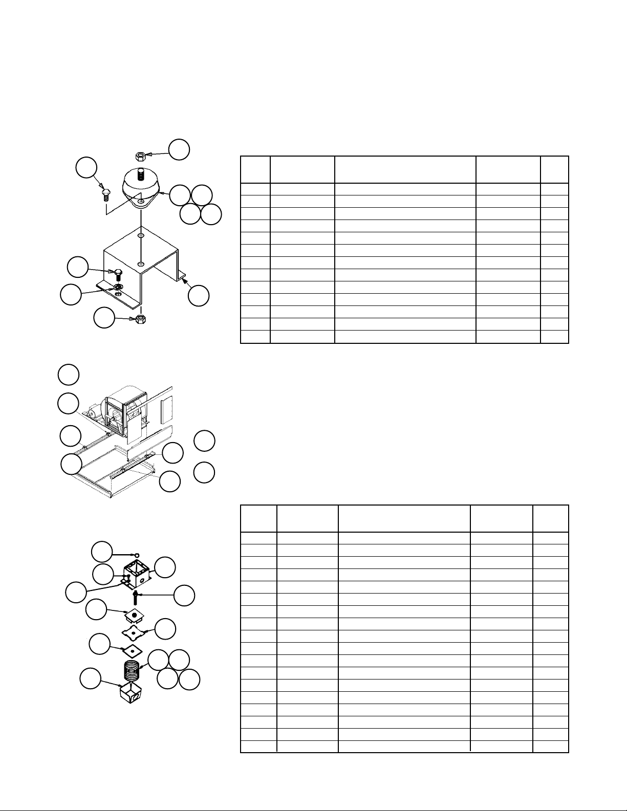
Section F- Supply Air Section
Fan Mounts- 33” Forward Curved Fan
Code 31= 33F1, 33F2, 33F3, 33M1, 33M2, 33M3
Until 11/04
90
161
or
61
63
or
163
92
89
91
Rubber Mounts
91
61 62
63
64
21
Mount Locations
162
or
62
164
or
64
Rubber Mounts (Code 31= 33F1 or 33M1)
Ref. Fan Motor Part Part Qty.
No. HP Description Number
21 All Channel- Mount Support 1 098316001 4
61 5, 7.5 Rubber Mount- Black 021639704 1
10 - 50 Rubber Mount- Red 021639701 1
62 5 - 40 Rubber Mount- Black 021639704 1
50 Rubber Mount- Red 021639701 1
63 5, 7.5 Rubber Mount- Black 021639704 1
10 - 25, 50 Rubber Mount- Red 021639701 1
30, 40 Rubber Mount- Green 021639703 1
64 All Rubber Mount- Red 021639701 1
89 All Screw- Cap, 3/8-16 X 1” 048878118 8
90 All Washer- Lock, 3/8” 048164812 8
91 All Nut- 1/2-13 032333305 12
92 All Screw- Cap, 1/2-13 X 1” 040499501 8
1
Prior to 5/02 p/n was 055512101.
Spring Mounts (Code 31= 33F2, 33F3, 33M2 or 33M3)
Ref. Fan Motor Part Part Qty.
No. HP Description Number
121 All Support Assembly 055606901 4
188
189
190
123
155
156
121
122
160
161 162
163
164
Spring Mounts
RoofPak Singlezone; RCS,RDT,RFS,RPS 080-135 “C” Rev. AD 07/12 RPL 700007000 / Page 63
122 All Screw Adjust Assembly 055528201 4
123 All Channel Assembly 055606801 4
155 All Plate- Gasket Retainer 055502101 4
156 All Support- Spring Locator 055502201 4
160 All Pad- Rubber Vibration 048447901 4
161 5 - 10 Mount- Spring, Black 048448502 1
15 - 50 Mount- Spring, Red 048448503 1
162 All Mount- Spring, Black 048448502 1
163 5 Mount- Spring, Black 048448502 1
7.5 - 25 Mount- Spring, Red 048448503 1
30 - 50 Mount- Spring, Green 048448504 1
164 5-10, 40, 50 Mount- Spring, Red 048448503 1
15 - 30 Mount- Spring, Black 048448502 1
188 All Nut- 5/8-11 040500002 4
189 All Screw- Cap, 3/8-16 X 1” 048878118 12
190 All Washer- Lock, 3/8” 048164812 8
N/S All Screw- Tapping, 1/4-20 046093809 8
Page 64

Section F- Supply Air Section
Fan Mounts- 33” Forward Curved Fan
Code 31= 33F1, 33F2, 33F3, 33M1, 33M2, 33M3
11/04 & Later
Rubber Mounts (Code 31= 33F1 or 33M1)
93
161
or
61
63
or
163
92
89
81
Rubber Mounts
91
61 62
63
21
91
64
Ref. Fan Motor Part Part Qty.
No. HP Description Number
21 All Channel- Mount Support 098316001 4
61 5, 7.5 Rubber Mount- Black 021639704 1
10 - 50 Rubber Mount- Red 021639701 1
62 5 - 40 Rubber Mount- Black 021639704 1
50 Rubber Mount- Red 021639701 1
63 5, 7.5 Rubber Mount- Black 021639704 1
10 - 25, 50 Rubber Mount- Red 021639701 1
30, 40 Rubber Mount- Green 021639703 1
64 All Rubber Mount- Red 021639701 1
81 All Nut 059992201 8
89 All Screw 112047201 8
91 All Nut- 1/2-13 032333305 12
92 All Screw- Cap, 1/2-13 X 1” 040499501 8
93 All Washer- Plain, 1/2” 048164812 8
Mount Locations
162
or
62
64
164
or
Spring Mounts (Code 31= 33F2 or 33M2) and
Seismic Spring (Code 31= 33F3 or 33M3)
Ref. Fan Motor Part Part Qty.
No. HP Description Number
121 All Mount
188
189
181
121
161 162
163
164
Spring Mounts
RoofPak Singlezone; RCS,RDT,RFS,RPS 080-135 “C” Rev. AD 07/12 RPL 700007000 / Page 64
Spring (C31= 33*2) 251783201 4
Seismic (C31= 33*3) 251783301 4
161 5, 7.5 Spring Mount- Purple 251784701 1
10 - 30 Spring Mount- Brown 251784801 1
40, 50 Spring Mount- Red 251785001 1
162 All Spring Mount- Brown 251784801 1
163 5, 7.5 Spring Mount- Brown 251784801 1
10 - 30 Spring Mount- Red 251784901 1
40, 50 Spring Mount- Red/Black 251785001 1
164 5 - 20 Spring Mount- Red 251784901 1
25 - 50 Spring Mount- Red/Black 251785001 1
181 All Nut
Spring (C31= 33*2) 059992201 12
Seismic (C31= 33*3) 111056301 20
188 All Nut 040500002 4
189 All Screw
Spring (C31= 33*2) 112047201 12
Seismic (C31= 33*3) 112047201 20
Page 65

Section F- Supply Air Section
Fan Mounts- 36” Forward Curved Fan
Code 31= 36F1, 36F2, 36F3, 36M1, 36M2, 36M3
Until 11/04
90
92
89
91
Rubber Mounts
91
61 62
63
21
64
Mount Locations
162
or
62
164
or
64
163
or
61161
or
63
Rubber Mounts (Code 31= 36F1 or 36M1)
Ref. Fan Motor Part Part Qty.
No. HP Description Number
21 All Channel- Mount Support 1 098316001 4
61 All Rubber Mount- Red 021639701 1
62 All Rubber Mount- Red 021639701 1
63 10 - 25 Rubber Mount- Red 021639701 1
30 - 50 Rubber Mount- Green 021639703 1
60, 75 Rubber Mount- Gray 021639705 1
64 All Rubber Mount- Red 021639701 1
89 All Screw- Cap, 3/8-16 X 1” 048878118 8
90 All Washer- Lock, 3/8” 048164812 8
91 All Nut- 1/2-13 032333305 12
92 All Screw- Cap, 1/2-13 X 1” 040499501 8
1
Prior to 5/02 p/n was 055512101.
Spring Mounts (Code 31= 36F2, 36F3, 36M2 or 36M3)
Ref. Fan Motor Part Part Qty.
No. HP Description Number
121 All Support Assembly 055606901 4
188
189
190
123
155
156
121
122
160
161 162
163
164
Spring Mounts
RoofPak Singlezone; RCS,RDT,RFS,RPS 080-135 “C” Rev. AD 07/12 RPL 700007000 / Page 65
122 All Screw Adjust Assembly 055528201 4
123 All Channel Assembly 055606801 4
155 All Plate- Gasket Retainer 055502101 4
156 All Support- Spring Locator 055502201 4
160 All Pad- Rubber Vibration 048447901 4
161 10 Mount- Spring, Black 048448502 1
15 - 75 Mount- Spring, Red 048448503 1
162 10 Mount- Spring, Red 048448503 1
15 - 75 Mount- Spring, Black 048448502 1
163 10 - 20 Mount- Spring, Red 048448503 1
25 - 75 Mount- Spring, Green 048448504 1
164 All Mount- Spring, Red 048448503 1
188 All Nut- 5/8-11 040500002 4
189 All Screw- Cap, 3/8-16 X 1” 048878118 12
190 All Washer- Lock, 3/8” 048164812 8
N/S All Screw- Tapping, 1/4-20 046093809 8
Page 66

Section F- Supply Air Section
Fan Mounts- 36” Forward Curved Fan
Code 31= 36F1, 36F2, 36F3, 36M1, 36M2, 36M3
11/04 & Later
92
93
89
81
Rubber Mounts
91
61 62
63
21
91
64
163
or
61161
or
63
Mount Locations
162
or
62
164
or
64
Rubber Mounts (Code 31= 36F1 or 36M1)
Ref. Fan Motor Part Part Qty.
No. HP Description Number
21 All Channel- Mount Support 098316001 4
61 All Rubber Mount- Red 021639701 1
62 All Rubber Mount- Red 021639701 1
63 10 - 25 Rubber Mount- Red 021639701 1
30 - 50 Rubber Mount- Green 021639703 1
60, 75 Rubber Mount- Gray 021639705 1
64 All Rubber Mount- Red 021639701 1
81 All Nut 059992201 8
89 All Screw 112047201 8
91 All Nut- 1/2-13 032333305 12
92 All Screw- Cap, 1/2-13 X 1” 040499501 8
93 All Washer- Plain, 1/2” 048164812 8
188
189
181
Spring Mounts
121
161 162
163
164
Spring Mounts (Code 31= 36F2 or 36M2) and
Seismic Spring (Code 31= 36F3 or 36M3)
Ref. Fan Motor Part Part Qty.
No. HP Description Number
121 All Mount
Spring (C31= 36*2) 251783201 4
Seismic (C31= 36*3) 251783301 4
161 10 - 20 Spring Mount- Brown 251784801 1
25 - 50 Spring Mount- Red 251784901 1
60, 75 Spring Mount- Red 251785001 1
162 All Spring Mount- Brown 251784801 1
163 10 - 20 Spring Mount- Red 251784901 1
25 - 50 Spring Mount- Red/Black 251785001 1
60, 75 Spring Mount- Red/Green 251785001 1
164 10 Spring Mount- Red 251784901 1
15 - 75 Spring Mount- Red/Black 251785001 1
181 All Nut
Spring (C31= 36*2) 059992201 12
Seismic (C31= 36*3) 111056301 20
188 All Nut 040500002 4
189 All Screw
Spring (C31= 36*2) 112047201 12
Seismic (C31= 36*3) 112047201 20
RoofPak Singlezone; RCS,RDT,RFS,RPS 080-135 “C” Rev. AD 07/12 RPL 700007000 / Page 66
Page 67

Section F- Supply Air Section
Fan Mounts- 40” Forward Curved Fan
Code 31= 40F1, 40F2, 40F3, 40M1, 40M2, 40M3
Until 11/04
90
92
89
91
Rubber Mounts
91
61 62
63
21
64
Mount Locations
162
or
62
164
or
64
163
or
61161
or
63
Rubber Mounts (Code 31= 40F1 or 40M1)
Ref. Fan Motor Part Part Qty.
No. HP Description Number
21 All Channel- Mount Support 1 098316001 4
61 All Rubber Mount- Red 021639701 1
62 All Rubber Mount- Red 021639701 1
63 10 - 25 Rubber Mount- Red 021639701 1
30 - 50 Rubber Mount- Green 021639703 1
60, 75 Rubber Mount- Gray 021639705 1
64 All Rubber Mount- Red 021639701 1
89 All Screw- Cap, 3/8-16 X 1” 048878118 8
90 All Washer- Lock, 3/8” 048164812 8
91 All Nut- 1/2-13 032333305 12
92 All Screw- Cap, 1/2-13 X 1” 040499501 8
1
Prior to 5/02 p/n was 055512101.
Spring Mounts (Code 31= 40F2, 40F3, 40M2 or 40M3)
Ref. Fan Motor Part Part Qty.
188
189
190
123
155
156
121
122
160
161 162
163
164
Spring Mounts
RoofPak Singlezone; RCS,RDT,RFS,RPS 080-135 “C” Rev. AD 07/12 RPL 700007000 / Page 67
No. HP Description Number
121 All Support Assembly 055606901 4
122 All Screw Adjust Assembly 055528201 4
123 All Channel Assembly 055606801 4
155 All Plate- Gasket Retainer 055502101 4
156 All Support- Spring Locator 055502201 4
160 All Pad- Rubber Vibration 048447901 4
161 All Mount- Spring, Red 048448503 1
162 10 - 25 Mount- Spring, Red 048448503 1
30 - 75 Mount- Spring, Black 048448502 1
163 10 - 20 Mount- Spring, Red 048448503 1
25 - 75 Mount- Spring, Green 048448504 1
164 All Mount- Spring, Red 048448503 1
188 All Nut- 5/8-11 040500002 4
189 All Screw- Cap, 3/8-16 X 1” 048878118 12
190 All Washer- Lock, 3/8” 048164812 8
N/S All Screw- Tapping, 1/4-20 046093809 8
Page 68

Section F- Supply Air Section
Fan Mounts- 40” Forward Curved Fan
Code 31= 40F1, 40F2, 40F3, 40M1, 40M2, 40M3
11/04 & Later
92
93
89
81
Rubber Mounts
91
61 62
63
21
91
64
163
or
61161
or
63
Mount Locations
162
or
62
164
or
64
Rubber Mounts (Code 31= 40F1 or 40M1)
Ref. Fan Motor Part Part Qty.
No. HP Description Number
21 All Channel- Mount Support 098316001 4
61 All Rubber Mount- Red 021639701 1
62 All Rubber Mount- Red 021639701 1
63 10 - 25 Rubber Mount- Red 021639701 1
30 - 50 Rubber Mount- Green 021639703 1
60, 75 Rubber Mount- Gray 021639705 1
64 All Rubber Mount- Red 021639701 1
81 All Nut 059992201 8
89 All Screw 112047201 8
91 All Nut- 1/2-13 032333305 12
92 All Screw- Cap, 1/2-13 X 1” 040499501 8
93 All Washer- Plain, 1/2” 048164812 8
188
189
181
Spring Mounts
121
161 162
163
164
Spring Mounts (Code 31= 40F2 or 40M2) and
Seismic Spring (Code 31= 40F3 or 40M3)
Ref. Fan Motor Part Part Qty.
No. HP Description Number
121 All Mount
Spring (C31= 40*2) 251783201 4
Seismic (C31= 40*3) 251783301 4
161 10, 15 Spring Mount- Brown 251784801 1
20 - 50 Spring Mount- Red 251784901 1
60, 75 Spring Mount- Red 251785001 1
162 10 - 20 Spring Mount- Red 251784901 1
25 - 75 Spring Mount- Brown 251784801 1
163 10, 15 Spring Mount- Red 251784901 1
20 - 50 Spring Mount- Red/Black 251785001 1
60, 75 Spring Mount- Red/Green 251785001 1
164 All Spring Mount- Red/Black 251785001 1
181 All Nut
Spring (C31= 40*2) 059992201 12
Seismic (C31= 40*3) 111056301 20
188 All Nut 040500002 4
189 All Screw
Spring (C31= 40*2) 112047201 12
Seismic (C31= 40*3) 112047201 20
RoofPak Singlezone; RCS,RDT,RFS,RPS 080-135 “C” Rev. AD 07/12 RPL 700007000 / Page 68
Page 69

Section F- Supply Air Section
Fan Mounts- 33” Airfoil Double Width Fan
Code 31= 33A1, 33A2, 33A3, 33V1, 33V2, 33V3
Until 11/04
or
61161
or
63163
Mount Locations
or
16262
or
16464
90
190
92
89
91
Rubber Mounts
188
189
123
155
156
Spring Mounts
91
61 62
121
122
160
161 162
163
63
164
21
64
Rubber Mounts (Code 31= 33A1 or 33V1)
Ref. Fan Motor Part Part Qty.
No. HP Description Number
21 All Channel- Mount Support 1 098316001 4
61 5, 7.5 Rubber Mount- Black 021639704 1
10 - 50 Rubber Mount- Red 021639701 1
62 All Rubber Mount- Black 021639704 1
63 5 - 25 Rubber Mount- Red 021639701 1
30 - 50 Rubber Mount- Green 021639703 1
64 5 - 25 Rubber Mount- Black 021639704 1
30 - 50 Rubber Mount- Red 021639701 1
89 All Screw- Cap, 3/8-16 X 1” 048878118 8
90 All Washer- Lock, 3/8” 048164812 8
91 All Nut- 1/2-13 032333305 12
92 All Screw- Cap, 1/2-13 X 1” 040499501 8
1
Prior to 5/02 p/n was 055512101.
Spring Mounts (Code 31= 33A2, 33A3, 33V2 or 33V3)
Ref. Fan Motor Part Part Qty.
No. HP Description Number
121 All Support Assembly 055606901 4
122 All Screw Adjust Assembly 055528201 4
123 All Channel Assembly 055606801 4
155 All Plate- Gasket Retainer 055502101 4
156 All Support- Spring Locator 055502201 4
160 All Pad- Rubber Vibration 048447901 4
161 5 - 10 Mount- Spring, Black 048448502 1
15,20,40,50 Mount- Spring, Red 048448503 1
25, 30 Mount- Spring, Green 048448504 1
162 All Mount- Spring, Black 048448502 1
163 5 Mount- Spring, Black 048448502 1
7.5 - 20 Mount- Spring, Red 048448503 1
25 - 50 Mount- Spring, Green 048448504 1
164 All Mount- Spring, Black 048448502 1
188 All Nut- 5/8-11 040500002 4
189 All Screw- Cap, 3/8-16 X 1” 048878118 12
190 All Washer- Lock, 3/8” 048164812 8
N/S All Screw- Tapping, 1/4-20 046093809 8
RoofPak Singlezone; RCS,RDT,RFS,RPS 080-135 “C” Rev. AD 07/12 RPL 700007000 / Page 69
Page 70

Section F- Supply Air Section
Fan Mounts- 33” Airfoil Double Width Fan
Code 31= 33A1, 33A2, 33A3, 33V1, 33V2, 33V3
11/04 & Later
92
93
89
81
Rubber Mounts
91
61 62
63
21
91
64
or
61161
or
63163
Mount Locations
or
16262
or
16464
Rubber Mounts (Code 31= 33A1 or 33V1)
Ref. Fan Motor Part Part Qty.
No. HP Description Number
21 All Channel- Mount Support 098316001 4
61 5, 7.5 Rubber Mount- Black 021639704 1
10 - 50 Rubber Mount- Red 021639701 1
62 All Rubber Mount- Black 021639704 1
63 5 - 25 Rubber Mount- Red 021639701 1
30 - 50 Rubber Mount- Green 021639703 1
64 5 - 25 Rubber Mount- Black 021639704 1
30 - 50 Rubber Mount- Red 021639701 1
81 All Nut 059992201 8
89 All Screw 112047201 8
91 All Nut- 1/2-13 032333305 12
92 All Screw- Cap, 1/2-13 X 1” 040499501 8
93 All Washer- Plain, 1/2” 048164812 8
Spring Mounts (Code 31= 33A2 or 33V2) and
Seismic Spring (Code 31= 33A3 or 33V3)
Ref. Fan Motor Part Part Qty.
188
189
181
121
161 162
163
164
Spring Mounts
RoofPak Singlezone; RCS,RDT,RFS,RPS 080-135 “C” Rev. AD 07/12 RPL 700007000 / Page 70
No. HP Description Number
121 All Mount
Spring (C31= 33*2) 251783201 4
Seismic (C31= 33*3) 251783301 4
161 5 , 7.5 Spring Mount- Purple 251784701 1
10 - 30 Spring Mount- Brown 251784801 1
40, 50 Spring Mount- Red 251784901 1
162 All Spring Mount- Brown 251784801 1
163 5, 7.5 Spring Mount- Brown 251784801 1
10 - 30 Spring Mount- Red 251784901 1
40, 50 Spring Mount- Red/Black 251785001 1
164 All Spring Mount- Red 251784901 1
181 All Nut
Spring (C31= 33*2) 059992201 12
Seismic (C31= 33*3) 111056301 20
188 All Nut 040500002 4
189 All Screw
Spring (C31= 33*2) 112047201 12
Seismic (C31= 33*3) 112047201 20
Page 71

Section F- Supply Air Section
Fan Mounts- 36” Airfoil Double Width Fan
Code 31= 36A1, 36A2, 36A3, 36V1, 36V2, 36V3
Until 11/04
or
61161
or
63163
Mount Locations
or
16262
or
16464
90
190
92
89
91
Rubber Mounts
188
189
123
155
156
Spring Mounts
91
61 62
121
122
160
161 162
163
63
164
21
64
Rubber Mounts (Code 31= 36A1 or 36V1)
Ref. Fan Motor Part Part Qty.
No. HP Description Number
21 All Channel- Mount Support 1 098316001 4
61 All Rubber Mount- Red 021639701 1
62 10, 30 - 50 Rubber Mount- Red 021639701 1
20, 60, 75 Rubber Mount- Black 021639704 1
63 10 - 25 Rubber Mount- Red 021639701 1
30 - 50 Rubber Mount- Green 021639703 1
60, 75 Rubber Mount- Gray 021639705 1
64 All Rubber Mount- Red 021639701 1
89 All Screw- Cap, 3/8-16 X 1” 048878118 8
90 All Washer- Lock, 3/8” 048164812 8
91 All Nut- 1/2-13 032333305 12
92 All Screw- Cap, 1/2-13 X 1” 040499501 8
1
Prior to 5/02 p/n was 055512101.
Spring Mounts (Code 31= 36A2, 36A3, 36V2 or 36V3)
Ref. Fan Motor Part Part Qty.
No. HP Description Number
121 All Support Assembly 055606901 4
122 All Screw Adjust Assembly 055528201 4
123 All Channel Assembly 055606801 4
155 All Plate- Gasket Retainer 055502101 4
156 All Support- Spring Locator 055502201 4
160 All Pad- Rubber Vibration 048447901 4
161 10 - 60 Mount- Spring, Red 048448503 1
75 Mount- Spring, Green 048448504 1
162 10 Mount- Spring, Red 048448503 1
15 - 60 Mount- Spring, Black 048448502 1
75 Mount- Spring, Blue 048448501 1
163 10 - 20 Mount- Spring, Red 048448503 1
25 - 75 Mount- Spring, Green 048448504 1
164 All Mount- Spring, Red 048448503 1
188 All Nut- 5/8-11 040500002 4
189 All Screw- Cap, 3/8-16 X 1” 048878118 12
190 All Washer- Lock, 3/8” 048164812 8
N/S All Screw- Tapping, 1/4-20 046093809 8
RoofPak Singlezone; RCS,RDT,RFS,RPS 080-135 “C” Rev. AD 07/12 RPL 700007000 / Page 71
Page 72

161
or
61
92
93
89
81
Rubber Mounts
Section F- Supply Air Section
Fan Mounts- 36” Airfoil Double Width Fan
Code 31= 36A1, 36A2, 36A3, 36V1, 36V2, 36V3
11/04 & Later
Rubber Mounts (Code 31= 36A1 or 36V1)
91
61 62
63
64
21
91
Mount Locations
Ref. Fan Motor Part Part Qty.
No. HP Description Number
21 All Channel- Mount Support 098316001 4
61 All Rubber Mount- Red 021639701 1
62 10, 30 - 50 Rubber Mount- Red 021639701 1
20, 60, 75 Rubber Mount- Black 021639704 1
63 10 - 25 Rubber Mount- Red 021639701 1
30 - 50 Rubber Mount- Green 021639703 1
60, 75 Rubber Mount- Gray 021639705 1
64 All Rubber Mount- Red 021639701 1
81 All Nut 059992201 8
89 All Screw 112047201 8
91 All Nut- 1/2-13 032333305 12
92 All Screw- Cap, 1/2-13 X 1” 040499501 8
93 All Washer- Plain, 1/2” 048164812 8
63
or
163
188
189
181
Spring Mounts
62
64
121
161 162
163
or
or
164
162
164
Spring Mounts (Code 31= 36A2 or 36V2) and
Seismic Spring (Code 31= 36A3 or 36V3)
Ref. Fan Motor Part Part Qty.
No. HP Description Number
121 All Mount
Spring (C31= 36*2) 251783201 4
Seismic (C31= 36*3) 251783301 4
161 10 , 15 Spring Mount- Brown 251784801 1
20 - 50 Spring Mount- Red 251784901 1
60, 75 Spring Mount- Red/Black 251785001 1
162 All Spring Mount- Brown 251784801 1
163 10, 15 Spring Mount- Red 251784901 1
20 - 50 Spring Mount- Red/Black 251785001 1
60, 75 Spring Mount- Red/Green 251785101 1
164 10 - 20 Spring Mount- Red 251784901 1
25 - 75 Spring Mount- Red/Black 251785001 1
181 All Nut
Spring (C31= 36*2) 059992201 12
Seismic (C31= 36*3) 111056301 20
188 All Nut 040500002 4
189 All Screw
Spring (C31= 36*2) 112047201 12
Seismic (C31= 36*3) 112047201 20
RoofPak Singlezone; RCS,RDT,RFS,RPS 080-135 “C” Rev. AD 07/12 RPL 700007000 / Page 72
Page 73

Section F- Supply Air Section
Fan Mounts- 40” Airfoil Double Width Fan
Code 31= 40A1, 40A2, 40A3, 40V1, 40V2, 40V3
Until 11/04
or
61161
or
63163
Mount Locations
or
16262
or
16464
90
190
92
89
91
Rubber Mounts
188
189
123
155
156
Spring Mounts
91
61 62
121
122
160
161 162
163
63
164
21
64
Rubber Mounts (Code 31= 40A1 or 40V1)
Ref. Fan Motor Part Part Qty.
No. HP Description Number
21 All Channel- Mount Support 1 098316001 4
61 10 - 50 Rubber Mount- Red 021639701 1
60, 75 Rubber Mount- Green 021639703 1
62 10 - 30 Rubber Mount- Red 021639701 1
40 - 75 Rubber Mount- Black 021639704 1
63 10, 15 Rubber Mount- Red 021639701 1
20 - 50 Rubber Mount- Green 021639703 1
60, 75 Rubber Mount- Gray 021639705 1
64 All Rubber Mount- Red 021639701 1
89 All Screw- Cap, 3/8-16 X 1” 048878118 8
90 All Washer- Lock, 3/8” 048164812 8
91 All Nut- 1/2-13 032333305 12
92 All Screw- Cap, 1/2-13 X 1” 040499501 8
1
Prior to 5/02 p/n was 055512101.
Spring Mounts (Code 31= 40A2, 40A3, 40V2 or 40V3)
Ref. Fan Motor Part Part Qty.
No. HP Description Number
121 All Support Assembly 055606901 4
122 All Screw Adjust Assembly 055528201 4
123 All Channel Assembly 055606801 4
155 All Plate- Gasket Retainer 055502101 4
156 All Support- Spring Locator 055502201 4
160 All Pad- Rubber Vibration 048447901 4
161 10 - 50 Mount- Spring, Red 048448503 1
60, 75 Mount- Spring, Green 048448504 1
162 All Mount- Spring, Black 048448502 1
163 10, 15 Mount- Spring, Red 048448503 1
20 - 75 Mount- Spring, Green 048448504 1
164 All Mount- Spring, Red 048448503 1
188 All Nut- 5/8-11 040500002 4
189 All Screw- Cap, 3/8-16 X 1” 048878118 12
190 All Washer- Lock, 3/8” 048164812 8
N/S All Screw- Tapping, 1/4-20 046093809 8
RoofPak Singlezone; RCS,RDT,RFS,RPS 080-135 “C” Rev. AD 07/12 RPL 700007000 / Page 73
Page 74

161
or
61
92
93
89
81
Rubber Mounts
Section F- Supply Air Section
Fan Mounts- 40” Airfoil Double Width Fan
Code 31= 40A1, 40A2, 40A3, 40V1, 40V2, 40V3
11/04 & Later
Rubber Mounts (Code 31= 40A1 or 40V1)
91
61 62
63
64
21
91
Mount Locations
Ref. Fan Motor Part Part Qty.
No. HP Description Number
21 All Channel- Mount Support 098316001 4
61 10 - 50 Rubber Mount- Red 021639701 1
60, 75 Rubber Mount- Green 021639703 1
62 10 - 30 Rubber Mount- Red 021639701 1
40 - 75 Rubber Mount- Black 021639704 1
63 10, 15 Rubber Mount- Red 021639701 1
20 - 50 Rubber Mount- Green 021639703 1
60, 75 Rubber Mount- Gray 021639705 1
64 All Rubber Mount- Red 021639701 1
81 All Nut 059992201 8
89 All Screw 112047201 8
91 All Nut- 1/2-13 032333305 12
92 All Screw- Cap, 1/2-13 X 1” 040499501 8
93 All Washer- Plain, 1/2” 048164812 8
63
or
163
188
189
181
Spring Mounts
62
64
121
161 162
163
or
or
164
162
164
Spring Mounts (Code 31= 40A2 or 40V2) and
Seismic Spring (Code 31= 40A3 or 40V3)
Ref. Fan Motor Part Part Qty.
No. HP Description Number
121 All Mount
Spring (C31= 40*2) 251783201 4
Seismic (C31= 40*3) 251783301 4
161 10 Spring Mount- Brown 251784801 1
15 - 30 Spring Mount- Red 251784901 1
40 - 75 Spring Mount- Red/Black 251785001 1
162 All Spring Mount- Brown 251784801 1
163 10 Spring Mount- Red 251784901 1
15 - 30 Spring Mount- Red/Black 251785001 1
40 - 75 Spring Mount- Red/Green 251785101 1
164 10 - 20 Spring Mount- Red 251784901 1
25 - 75 Spring Mount- Red/Black 251785001 1
181 All Nut
Spring (C31= 40*2) 059992201 12
Seismic (C31= 40*3) 111056301 20
188 All Nut 040500002 4
189 All Screw
Spring (C31= 40*2) 112047201 12
Seismic (C31= 40*3) 112047201 20
RoofPak Singlezone; RCS,RDT,RFS,RPS 080-135 “C” Rev. AD 07/12 RPL 700007000 / Page 74
Page 75
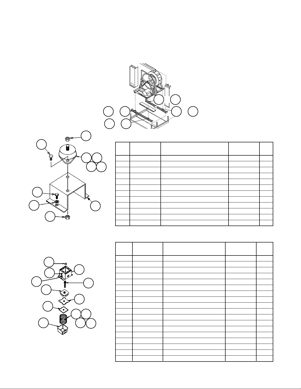
Section F- Supply Air Section
Fan Mounts- 44” AFSW- RDT Units
Code 31= 44B1, 44B2, 44B3, 44W1, 44W2, 44W3
Until 11/04
Mount Locations
or
16262
90
190
92
89
91
Rubber Mounts
188
189
123
155
156
Spring Mounts
91
61 62
121
122
160
161 162
163
63
164
21
64
or
61161
or
63163
or
16464
Rubber Mounts (Code 31= 44B1 or 44W1)
Ref. Fan Motor Part Part Qty.
No. HP Description Number
21 All Channel- Mount Support 1 098316001 4
61 7.5 - 25 Rubber Mount- Black 021639704 1
30 - 60 Rubber Mount- Red 021639701 1
62 All Rubber Mount- Red 021639701 1
63 7.5, 10 Rubber Mount- Black 021639704 1
15 - 50 Rubber Mount- Red 021639701 1
60 Rubber Mount- Green 021639703 1
64 All Rubber Mount- Red 021639701 1
89 All Screw- Cap, 3/8-16 X 1” 048878118 8
90 All Washer- Lock, 3/8” 048164812 8
91 All Nut- 1/2-13 032333305 12
92 All Screw- Cap, 1/2-13 X 1” 040499501 8
1
Prior to 5/02 p/n was 055512101.
Spring Mounts (Code 31= 44B2, 44B3, 44W2 or 44W3)
Ref. Fan Motor Part Part Qty.
No. HP Description Number
121 All Support Assembly 055606901 4
122 All Screw Adjust Assembly 055528201 4
123 All Channel Assembly 055606801 4
155 All Plate- Gasket Retainer 055502101 4
156 All Support- Spring Locator 055502201 4
160 All Pad- Rubber Vibration 048447901 4
161 7.5 - 40 Mount- Spring, Black 048448502 1
50, 60 Mount- Spring, Red 048448503 1
162 7.5 - 30 Mount- Spring, Red 048448503 1
40 - 60 Mount- Spring, Black 048448502 1
163 7.5 - 20 Mount- Spring, Black 048448502 1
25 - 50 Mount- Spring, Red 048448503 1
60 Mount- Spring, Green 048448504 1
164 All Mount- Spring, Red 048448503 1
188 All Nut- 5/8-11 040500002 4
189 All Screw- Cap, 3/8-16 X 1” 048878118 12
190 All Washer- Lock, 3/8” 048164812 8
N/S All Screw- Tapping, 1/4-20 046093809 8
RoofPak Singlezone; RCS,RDT,RFS,RPS 080-135 “C” Rev. AD 07/12 RPL 700007000 / Page 75
Page 76

Section F- Supply Air Section
Fan Mounts- 44” AFSW- Draw-Thru/No Heat Units
Code 31= 44B1, 44B2, 44B3, 44W1, 44W2, 44W3
11/04 & Later
Mount Locations
162
or
62
or
61161
or
63163
64
164
or
92
93
89
81
Rubber Mounts
188
189
181
Spring Mounts
91
61 62
91
121
161 162
163
63
21
164
64
Rubber Mounts (Code 31= 44B1 or 44W1)
Ref. Fan Motor Part Part Qty.
No. HP Description Number
21 All Channel- Mount Support 098316001 4
61 7.5 - 25 Rubber Mount- Black 021639704 1
30 - 60 Rubber Mount- Red 021639701 1
62 All Rubber Mount- Red 021639701 1
63 7.5, 10 Rubber Mount- Black 021639704 1
15 - 50 Rubber Mount- Red 021639701 1
60 Rubber Mount- Green 021639703 1
64 All Rubber Mount- Red 021639701 1
81 All Nut 059992201 8
89 All Screw 112047201 8
91 All Nut- 1/2-13 032333305 12
92 All Screw- Cap, 1/2-13 X 1” 040499501 8
93 All Washer- Plain, 1/2” 048164812 8
Spring Mounts (Code 31= 44B2 or 44W2) and
Seismic Spring (Code 31= 44B3 or 44W3)
Ref. Fan Motor Part Part Qty.
No. HP Description Number
121 All Mount
Spring (C31= 44*2) 251783201 4
Seismic (C31= 44*3) 251783301 4
161 7.5 - 20 Spring Mount- Purple 251784701 1
25 - 50 Spring Mount- Brown 251784801 1
60 Spring Mount- Red 251784901 1
162 All Spring Mount- Brown 251784801 1
163 7.5 - 25 Spring Mount- Brown 251784801 1
30 - 50 Spring Mount- Red 251784901 1
60 Spring Mount- Red/Black 251785001 1
164 All Spring Mount- Red 251784901 1
181 All Nut
Spring (C31= 44*2) 059992201 12
Seismic (C31= 44*3) 111056301 20
188 All Nut 040500002 4
189 All Screw
Spring (C31= 44*2) 112047201 12
Seismic (C31= 44*3) 112047201 20
RoofPak Singlezone; RCS,RDT,RFS,RPS 080-135 “C” Rev. AD 07/12 RPL 700007000 / Page 76
Page 77

Section F- Supply Air Section
Fan Mounts- 49” AFSW- RDT Units
Code 31= 49B1, 49B2, 49B3, 49W1, 49W2, 49W3
Until 11/04
Mount Locations
or
16262
90
190
92
89
91
Rubber Mounts
188
189
123
155
156
Spring Mounts
91
61 62
121
122
160
161 162
163
63
164
21
64
or
61161
or
63163
or
16464
Rubber Mounts (Code 31= 49B1 or 49W1)
Ref. Fan Motor Part Part Qty.
No. HP Description Number
21 All Channel- Mount Support 1 098316001 4
61 All Rubber Mount- Red 021639701 1
62 All Rubber Mount- Red 021639701 1
63 7.5 - 30 Rubber Mount- Red 021639701 1
40 - 75 Rubber Mount- Green 021639703 1
64 7.5 - 30 Rubber Mount- Red 021639701 1
40 - 75 Rubber Mount- Green 021639703 1
89 All Screw- Cap, 3/8-16 X 1” 048878118 8
90 All Washer- Lock, 3/8” 048164812 8
91 All Nut- 1/2-13 032333305 12
92 All Screw- Cap, 1/2-13 X 1” 040499501 8
1
Prior to 5/02 p/n was 055512101.
Spring Mounts (Code 31= 49B2, 49B3, 49W2 or 49W3)
Ref. Fan Motor Part Part Qty.
No. HP Description Number
121 All Support Assembly 055606901 4
122 All Screw Adjust Assembly 055528201 4
123 All Channel Assembly 055606801 4
155 All Plate- Gasket Retainer 055502101 4
156 All Support- Spring Locator 055502201 4
160 All Pad- Rubber Vibration 048447901 4
161 7.5 - 60 Mount- Spring, Red 048448503 1
75 Mount- Spring, Green 048448504 1
162 All Mount- Spring, Red 048448503 1
163 7.5 - 30 Mount- Spring, Red 048448503 1
40 - 75 Mount- Spring, Green 048448504 1
164 7.5 Mount- Spring, Red 048448503 1
10 - 75 Mount- Spring, Green 048448504 1
188 All Nut- 5/8-11 040500002 4
189 All Screw- Cap, 3/8-16 X 1” 048878118 12
190 All Washer- Lock, 3/8” 048164812 8
N/S All Screw- Tapping, 1/4-20 046093809 8
RoofPak Singlezone; RCS,RDT,RFS,RPS 080-135 “C” Rev. AD 07/12 RPL 700007000 / Page 77
Page 78

Section F- Supply Air Section
Fan Mounts- 49” AFSW- RDT Units
Code 31= 49B1, 49B2, 49B3, 49W1, 49W2, 49W3
11/04 & Later
or
16262
92
93
89
81
Rubber Mounts
188
189
181
Spring Mounts
91
61 62
91
121
161 162
163
63
21
164
64
or
61161
or
63163
or
16464
Rubber Mounts (Code 31= 49B1 or 49W1)
Ref. Fan Motor Part Part Qty.
No. HP Description Number
21 All Channel- Mount Support 098316001 4
61 All Rubber Mount- Red 021639701 1
62 All Rubber Mount- Red 021639701 1
63 7.5 - 30 Rubber Mount- Red 021639701 1
40 - 75 Rubber Mount- Green 021639703 1
64 7.5 - 30 Rubber Mount- Red 021639701 1
40 - 75 Rubber Mount- Green 021639703 1
81 All Nut 059992201 8
89 All Screw 112047201 8
91 All Nut- 1/2-13 032333305 12
92 All Screw- Cap, 1/2-13 X 1” 040499501 8
93 All Washer- Plain, 1/2” 048164812 8
Spring Mounts (Code 31= 49B2 or 49W2) and
Seismic Spring (Code 31= 49B3 or 49W3)
Ref. Fan Motor Part Part Qty.
No. HP Description Number
121 All Mount
Spring (C31= 44*2) 251783201 4
Seismic (C31= 44*3) 251783301 4
161 7.5 - 30 Spring Mount- Red 251784901 1
40, 50 Spring Mount- Red/Black 251785001 1
60, 75 Spring Mount- Red/Green 251785101 1
162 All Spring Mount- Red/Black 251785001 1
163 7.5 - 20 Spring Mount- Red 251784901 1
25 - 75 Spring Mount- Red/Black 251785001 1
164 All Spring Mount- Red/Black 251785001 1
181 All Nut
Spring (C31= 44*2) 059992201 12
Seismic (C31= 44*3) 111056301 20
188 All Nut 040500002 4
189 All Screw
Spring (C31= 44*2) 112047201 12
Seismic (C31= 44*3) 112047201 20
RoofPak Singlezone; RCS,RDT,RFS,RPS 080-135 “C” Rev. AD 07/12 RPL 700007000 / Page 78
Page 79

Section F- Supply Air Section
Supply Air Fan Motors
All motors listed below are Across-The-Line start (C10= AL or PW). There are some units that have Part-Winding start motors
(C10= PP or PS). These units have motors 15HP and greater and are 208V or 230V only. Contact Daikin McQuay Parts if a PW
replacement motor is needed.
H.P. Unit ODP ODP HiEff ODP PrEff. TEFC TEFC HiEff TEFC PrEff
Voltage C32= *AY C32= *EY C32= *JY C32= *GY C32= *HY C32= *KY
C09= 12
5 208/60/3 020521000 039447600 065817200 025435800 049186800 065819500
7.5 208/60/3 020524800 037530300 065817300 024581000 047665900 065819600
10 208/60/3 021486000 038999000 065817400 025436900 047666100 065819700
15 208/60/3 049100600 039896200 065817500 049100700 049186900 065819800
20 208/60/3 049101200 039895800 065817600 049101300 049187000 065819900
25 208/60/3 034243300 039448900 065817700 049100900 049187100 065820000
30 208/60/3 049101500 041775200 205066500 049101600 049187200 205066800
40 208/60/3 030389500 041775300 205067100 049101900 049187300 205070700
50 208/60/3 049102200 041775400 205067500 049102300 049187400 205091600
60 208/60/3 049102600 041775800 205067700 048443300 049187500
75 208/60/3 049189900 041775700 205069100 049103100 049187600
C09= 29
5 230/60/3 019664800 039442500 065818200 020520600 040161200 065820200
7.5 230/60/3 019855100 039448700 065818300 020522100 049100500 065820300
10 230/60/3 017859600 039446500 065818400 024211500 044691100 065820400
15 230/60/3 023256100 039446600 065818500 026215800 038689700 065820500
20 230/60/3 022772100 039448800 065818600 031314500 040161300 065820600
25 230/60/3 029863500 039896100 065818700 032242500 040161400 065820700
30 230/60/3 040626800 040626800 205066600 032243100 049025300 205066900
40 230/60/3 041770000 041770000 205067200 048448000 048448000 205069200
50 230/60/3 039899200 039899200 205067600 040161600 040161600 205069400
60 230/60/3 041775500 041775500 065819100 046748300 046748300 205069600
75 230/60/3 041775600 041775600 205070300 031327700 049187800 205069900
C09= 27
5 460/60/3 019664800 039442500 065818200 020520600 040161200 065820200
7.5 460/60/3 019855100 039448700 065818300 020522100 049100500 065820300
10 460/60/3 017859600 039446500 065818400 024211500 044691100 065820400
15 460/60/3 023256100 039446600 065818500 026215800 038689700 065820500
20 460/60/3 022772100 039448800 065818600 031314500 040161300 065820600
25 460/60/3 029863500 039896100 065818700 032242500 040161400 065820700
30 460/60/3 040626800 040626800 205066600 032243100 049025300 205066900
40 460/60/3 041770000 041770000 205067200 048448000 048448000 205069200
50 460/60/3 039899200 039899200 205067600 040161600 040161600 205069400
60 460/60/3 041775500 041775500 065819100 046748300 046748300 205069600
75 460/60/3 041775600 041775600 205070300 031327700 049187800 205069900
C09= 37
5 575/60/3 046741800 046741900 205168900 048169900 049188400 046514600
7.5 575/60/3 046744400 047443300 205168800 040160100 049188500 046514700
10 575/60/3 031326700 047443400 205168600 049763700 049188600 065821400
15 575/60/3 046744500 047443500 205166600 046749000 049185200 065821500
20 575/60/3 046744600 049181100 205166800 049186200 049188700 065821600
25 575/60/3 047133700 049181200 205166900 049186300 049188800 065821700
30 575/60/3 047137600 049181300 205066700 049126100 049188900 205067000
40 575/60/3 047138000 049181400 205067300 049186400 049189000 205069300
50 575/60/3 047133800 049181500 205091800 049126200 049189100 205069500
60 575/60/3 046747600 049181600 205069000 049186500 049189200 205069800
75 575/60/3 049181700 049181800 205070400 049186600 049189300 205070000
RoofPak Singlezone; RCS,RDT,RFS,RPS 080-135 “C” Rev. AD 07/12 RPL 700007000 / Page 79
Page 80

41
Section F- Supply Air Section
Belt Guard
Code 49= A, C, D or F
Air Foil Double Width (AFDW) or Forward Curved Fans (FCLP or FCMP)
Ref. Part Part Fan Size
40
No. Description Number 33” 36” 40”
40 Grille Assembly 055606004 1
Grille Assembly 055606005 1
Grille Assembly 055606006 1
41 Belt Guard Assembly 055606014 1
Belt Guard Assembly 055606015 1
Belt Guard Assembly 055606016 1
Air Foil Single Width (AFSW) with
Side Discharge (C40= H),
Main Control Box (C08= S or F)
The main control box is mounted in this section on RDT
units (the supply air section is mounted directly to the condenser section).
81
80
Air Foil Single Width (AFSW) with
Bottom Discharge (C40= G),
Main Control Box (C08= S or F)
The main control box is mounted in this section on RDT
units (the supply air section is mounted directly to the condenser section).
83
Air Foil Single Width (AFSW) with
Side Discharge (C40= S),
No Control Box (C08= P or D)
RPS units (Main Control Box is mounted in the Discharge Plenum Section K).
82
81
80
Air Foil Single Width (AFSW) with
Bottom Discharge (C40= B),
No Control Box (C08= P or D or Y)
RPS units (Main Control Box is mounted in the
Discharge Plenum Section K).
83
82
81
81
80
Ref. Part Part Fan Size
No. Description Number 44” 49”
80 Grille Assy 056259211 1
Grille Assy 056259221 1
81 Grille Assy 056259212 1
Grille Assy 056259222 1
82 Grille Assy 056259213 1 1
83 Grille Assy 056259214 1 1
RoofPak Singlezone; RCS,RDT,RFS,RPS 080-135 “C” Rev. AD 07/12 RPL 700007000 / Page 80
80
Page 81

Section F- Supply Air Section
Inverters & Inverter Bypass Control Box
Until 3/05 (Code 8= P)**
Motor HP 5 - 25 (Code 22 or Code 32= J, K L, M, N or P)
Inverters may be located in a separate section (Code 14= 1, 2 or 4, only inverters WITH bypass may be installed in a separate section), or the
Supply Air Section (Code 14= 3, 5, 6, 7, 8 or 9). The inverter and bypass controls are the same regardless of the installation location, although
the sheet metal components differ. The diagrams shown below apply to either a return air or supply air inverter (both may be installed if code
14= 5). Even if Code 14= 8 or 9— where only a return air fan inverter is called for— the inverter and bypass controls are still installed in the
Supply Air Section.
** If unit was built between 10/04 and 3/05 visual inspection is required to confirm installed components.
40
M30A/M30B (Supply)
M40A/M40B (Return)
60
PB10 (Supply)
PB20 (Return)
62
OR
M10 (Sup-
ply)
M20 (Re-
turn)
40
Supply Air and Return Air Fan
Inverter without Bypass.
(Code 14= 7)
50
Supply Air or Return Air Fan
Inverter w/ Bypass Control Box.
OL10 (Supply)
OL20 (Return)
61
61A
Bypass Controls
Detail
40
Supply Air or Return Air Fan
Inverter without Bypass.
(Code 14= 6, 7, 9)
(Code 14= 3, 5, 8)
Motor Horsepower
5 7.5, 10 15 20 25
Ref Sch. Part Part
208V
230V
460V
575V
208V
230V
460V
575V
208V
230V
460V
575V
208V
230V
460V
575V
No. Sym. Description Number
208V
40 AFD10,20 Inverter 12 pages after next
50 Gasket 055940207 1 1 1 1 1 1 1 1 1 1 1 1 1 1 1 1 1 1 1 1
60 M30AB Contactor 066814301 1 1 1 1 1 1
M40AB 066814303 1 1 1 1 1 1
066814304 1 1 1 1
066814305 1
066814306 1 1
066814307 1
61 OL10, 20 Overload
61A Heater- OL
1
1
62 PB10,20 Power Block 030372715 1 1 1 1 1 1 1 1 1 1 1 1 1 1 1 1 1 1 1 1
M10, 20 Contactor
1
For part numbers for the OL10 or OL20 and associated heater see “Section N- Main Control Box Power Panel Until 3/05”.
2
The inverter bypass box originally had a contactor (M10 or M20) installed. This was replaced with the Power Block. If a contactor
is needed see “Section N- Main Control Box Power Panel Until 3/05” for part number(s).
2
230V
460V
575V
RoofPak Singlezone; RCS,RDT,RFS,RPS 080-135 “C” Rev. AD 07/12 RPL 700007000 / Page 81
Page 82
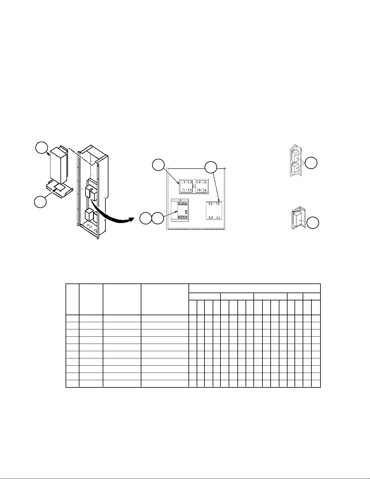
Section F- Supply Air Section
Inverters & Inverter Bypass Control Box
Until 3/05 (Code 8= P)**
Motor HP 30 - 75 (Code 22 or Code 32= Q, R, S, T or U)
Inverters may be located in a separate section (Code 14= 1, 2 or 4, only inverters WITH bypass may be installed in a separate section), or the
Supply Air Section (Code 14= 3, 5, 6, 7, 8 or 9). The inverter and bypass controls are the same regardless of the installation location, although
the sheet metal components differ. The diagrams shown below apply to either a return air or supply air inverter (both may be installed if code
14= 5). Even if Code 14= 8 or 9— where only a return air fan inverter is called for— the inverter and bypass controls are still installed in the
Supply Air Section.
** If unit was built between 10/04 and 3/05 visual inspection is required to confirm installed components.
40
50
Supply Air or Return Air Fan
Inverter w/ Bypass Control Box.
(Code 14= 3, 5, 8)
Motor Horsepower
30 40 50 60 75
Ref Sch. Part Part
No. Sym. Description Number
40 AFD10,20 Inverter 11 pages after next
50 Gasket 055940207 1 1 1 1 1 1 1 1 1 1
60 M30AB Contactor 066814304 1 1
M40AB 066814306 1 1
066814307 1 1 1
066814308 1 1 1 1 1 1
61 OL10, 20 Overload
61A Heater- OL
62 PB10,20 Power Block 030372715 1 1 1 1 1 1 1 1 1 1 1 1 1 1
M10, 20 Contactor
1
For part numbers for the OL10 or OL20 and associated heater see “Section N- Main Control Box Power Panel
Until 3/05”.
2
The inverter bypass box originally had a contactor (M10 or M20) installed. This was replaced with the Power Block.
If a contactor is needed see “Section N- Main Control Box Power Panel Until 3/05” for part number(s).
M30A/M30B (Supply)
M40A/M40B (Return)
60
OL10 (Supply)
OL20 (Return)
61
61A
1
1
2
PB10 (Supply)
PB20 (Return)
62
Bypass Controls
Detail
208V
230V
460V
575V
OR
208V
M10 (Sup-
ply)
M20 (Re-
turn)
Supply Air and Return Air Fan
Inverter without Bypass.
(Code 14= 7)
Supply Air or Return Air Fan
Inverter without Bypass.
(Code 14= 6, 7, 9)
230V
460V
575V
208V
230V
460V
575V
460V
575V
40
40
460V
575V
RoofPak Singlezone; RCS,RDT,RFS,RPS 080-135 “C” Rev. AD 07/12 RPL 700007000 / Page 82
Page 83

Section F- Supply Air Section
Inverters & Inverter Bypass Control Box
3/05 to 10/06 (Code 8= D)**
Motor HP 5 (Code 22= J; or Code 32= J)
Diagrams
Inverters may be located in a separate section (Code 14= 1, 2 or 4, only inverters WITH bypass may be installed in a separate
section), or the Supply Air Section (Code 14= 3, 5, 6, 7, 8 or 9). The inverter and bypass controls are the same regardless of
the installation location, although the sheet metal components differ. The diagrams shown below apply to either a return air or
supply air inverter (both may be installed if code 14= 5). Even if Code 14= 8 or 9— where only a return air fan inverter is called
for— the inverter and bypass controls are still installed in the Supply Air Section.
** If unit was built between 10/04 & 3/05 or 10/06 & 12/06 visual inspection is required to confirm installed components.
LR10 (Supply)
71
LR20 (Return)
40
50
Supply Air or Return Air Fan Inverter
with Bypass Control Box.
(Code 14= 3, 5, 8)
Two boxes installed if Code 14= 5
40
Supply Air and Return Air Fan
Inverter without Bypass.
(Code 14= 7)
MMP30 (Supply)
MMP40 (Return)
70
Bypass Controls Detail
70
78
72
M30B/M30I (Supply)
M40B/M40I (Return)
75
72
73
40
74
76
Supply Air or Return Air Fan
Inverter without Bypass.
77
(Code 14= 6, 7, 9)
MMP & Contactor Link Detail
RoofPak Singlezone; RCS,RDT,RFS,RPS 080-135 “C” Rev. AD 07/12 RPL 700007000 / Page 83
Page 84

Section F- Supply Air Section
Inverters & Inverter Bypass Control Box
3/05 to 10/06 (Code 8= D)**
Motor HP 5 (Code 22= J; or Code 32= J)
Components
** If unit was built between 10/04 & 3/05 or 10/06 & 12/06 visual inspection is required to confirm installed components.
Motor HP
5
Ref Sch. Part Part
No. Sym. Description Number
40 AFD10,20 Inverter- see 9 pages after next
50 Gasket 055940207 1 1 1 1
70 MMP30,40 Motor Control 349934009 1
349934010 1
349934012 1 1
71 LR10,20 Line Reactor- see page after inverters
72 M30B,I Contactor 349933102 1 1
M40B,I 349933201 1
349933301 1
73 Alarm- Short Circuit 349933903 1 1 1 1
74 Alarm/Aux. Contact 349933902 1 1 1 1
75 Line Shield 349933001 1 1 1 1
76 Cover- Contactor 349932801 2 2
349932802 2
349932803 2
77 Aux. Contact Block N/A
78 Link Module 349932902 1 1
349932903 1
349932904 1
N/A= Not Applicable.
208V
230V
460V
575V
RoofPak Singlezone; RCS,RDT,RFS,RPS 080-135 “C” Rev. AD 07/12 RPL 700007000 / Page 84
Page 85

Section F- Supply Air Section
Inverters & Inverter Bypass Control Box
3/05 to 10/06 (Code 8= D)**
Motor HP 7.5 - 25 (Code 22 or Code 32= K, L, M, N or P)
Diagrams
** If unit was built between 10/04 & 3/05 or 10/06 & 12/06 visual inspection is required to confirm installed components.
LR10 (Supply)
71
LR20 (Return)
70
40
50
Supply Air or Return Air Fan
Inverter w/Bypass Control
Box.
(Code 14= 3, 5, 8)
Two boxes installed if C14= 5
MMP30 (Supply)
MMP40 (Return)
M30B/M30I (Supply)
72
M40B/M40I (Return)
Bypass Controls Detail
70
75
73
78
72
73
72
MMP & Contactor Link Detail
MMP p/n 349934109
70
79
72
77
76
70
78
72
77
80
78
73
74
MMP & Contactor Link Detail
MMP p/n 3499340xx
70
79
72
77
72
76
77
MMP & Contactor Link Detail
MMP p/n 349934105,06,07,08
RoofPak Singlezone; RCS,RDT,RFS,RPS 080-135 “C” Rev. AD 07/12 RPL 700007000 / Page 85
MMP & Contactor Link Detail
MMP p/n 349938606
Page 86

Section F- Supply Air Section
Inverters & Inverter Bypass Control Box
3/05 to 10/06 (Code 8= D)**
Motor HP 7.5- 25 (Code 22 or Code 32= K, L, M, N or P)
Components
** If unit was built between 10/04 & 3/05 or 10/06 & 12/06 visual inspection is required to confirm installed components.
Motor Horsepower
7.5 10 15 20 25
Ref Sch. Part Part
No. Sym. Description Number
208V
230V
460V
575V
208V
230V
460V
575V
208V
230V
460V
575V
208V
230V
460V
575V
208V
230V
460V
40 AFD10,20 Inverter- see 7 pages after next
50 Gasket 055940207 1 1 1 1 1 1 1 1 1 1 1 1 1 1 1 1 1 1 1 1
70 MMP30,40 Motor Control 349934010 1
349934011 1 1
349934012 1
349934013 1
349934014 1 1
349934105 1 1
349934106 1 1 1 1
349934107 1
349934108 1 1
349934109 1 1 1
349938606 1
71 LR10,20 Line Reactor- see page after inverters
72 M30B,I Contactor 349933102 1 1 1
M40B,I 349933201 1
349933301 1 1 1
349933401 1
349933501 1 1 1 1 1 1 1 1
349933601 1 1 1 1
73 Alarm- Short Circuit 349933903 1 1 1 1 1 1 1 1 1 1 1 1 1 1 1 1 1 1 1
74 Alarm/Aux. Contact 349933902 1 1 1 1 1 1 1
75 Line Shield 349933001 1 1 1 1 1 1 1
76 Cover- Contactor 349932801 2 2 2
349932802 2
349932803 2 2 2
349932804 2
349932805 2 2 2 2 2 2 2 2
77 Aux. Contact Block 349933804 1 1 1 1 1 1 1 1 1 1 1 1
78 Link Module 349932902 1 1 1
349932903 1
349932904 1 1 1
349932906 1
349932907 1 1 1 1 1 1 1 1
79 Aux. Contact 349938701 1
80 Lug 349938801 6
575V
RoofPak Singlezone; RCS,RDT,RFS,RPS 080-135 “C” Rev. AD 07/12 RPL 700007000 / Page 86
Page 87

Section F- Supply Air Section
Inverters & Inverter Bypass Control Box
3/05 to 10/06 (Code 8= D)**
Motor HP 30 - 75 (Code 22= Q, R, S, T; Code 32= Q, R, S, T or U)
Diagrams
** If unit was built between 10/04 and 3/05 visual inspection is required to confirm installed components.
LR10 (Supply)
71
LR20 (Return)
70
40
50
Supply Air or Return Air Fan
Inverter w/Bypass Control
Box.
(Code 14= 3, 5, 8)
Two boxes installed if C14= 5
MMP30 (Supply)
MMP40 (Return)
M30B/M30I (Supply)
72
M40B/M40I (Return)
Bypass Controls Detail
73
78
72
70
70
73
72
MMP & Contactor Link Detail
MMP p/n 349934108, 09
79
72
77
76
78
72
77
70
79
72
80
77
MMP & Contactor Link Detail
MMP p/n 349938606, 07
MMP & Contactor Link Detail
MMP p/n 349934107
RoofPak Singlezone; RCS,RDT,RFS,RPS 080-135 “C” Rev. AD 07/12 RPL 700007000 / Page 87
Page 88

Section F- Supply Air Section
Inverters & Inverter Bypass Control Box
3/05 to 10/06 (Code 8= D)**
Motor HP 30 - 75 (Code 22= Q, R, S, T; Code 32= Q, R, S, T or U)
Components
Motor Horsepower
30 40 50 60 75
Ref Sch. Part Part
No. Sym. Description Number
208V
230V
460V
575V
208V
230V
460V
575V
208V
230V
460V
575V
208V
230V
460V
575V
208V
230V
460V
40 AFD10,20 Inverter- see 5 pages after next
50 Gasket 055940207 1 1 1 1 1 1 1 1 1 1 1 1 1 1
70 MMP30 Motor Control 349934107 1 1 1
MMP40 349934108 1
349934109 1 1 1
349938606 1 1 1 1
349938607 1 1
71 LR10,20 Line Reactor- see page after inverters
72 M30B,I Contactor 349933501 1
M40B,I 349933502 1 1
349933601 1 1 1 1 1
349933602 1 1 1 1
349933701 1
73 Alarm- Short Circuit 349933903 1 1 1 1 1 1 1
76 Cover- Contactor 349932805 1 1 1
77 Aux. Contact Block 349933804 1 1 1 1 1 1 1
575V
78 Link Module 349932907 1 1 1
79 Aux. Contact 349938701 1 1 1 1 1 1
1 31
80 Lug 349938801 6 6 3
1
Also requires 3 ring terminals.
RoofPak Singlezone; RCS,RDT,RFS,RPS 080-135 “C” Rev. AD 07/12 RPL 700007000 / Page 88
6 6
Page 89

Section F- Supply Air Section
Inverters & Inverter Bypass Control Box
1/07 & Later** (Code 8= D)
Motor HP 5 (Code 22= J; or Code 32= J)
** If unit was built between 10/06 & 12/06 visual inspection is required to confirm installed components.
LR10 (Supply)
71
LR20 (Return)
40
50
Supply Air or Return Air Fan Inverter
w/ Bypass Control Box.
(Code 14= 3, 5, 8)
Two boxes installed if Code 14= 5
40
Supply Air and Re-
turn Air Fan Inverter
without Bypass.
(Code 14= 7)
MMP30 (Supply)
MMP40 (Return)
40
Supply Air or
Return Air Fan
Inverter without
Bypass.
(Code 14= 6, 7, 9)
70
MMP & Auxiliary
Contact Detail
Until 10/07
MMP & Auxiliary
Contact Detail
10/07 & Later
73
74
72
Bypass Controls Detail
72
M30B/M30I (Supply)
M40B/M40I (Return)
70
73
70
MMP & Contactor
Link Detail
Motor HP
5
Ref Sch. Part Part
No. Sym. Description Number
208V
230V
460V
575V
40 AFD10,20 Inverter- see 4 pages after next
50 Gasket 055940207 1 1 1 1
70 MMP30,40 Motor Control 349934049 1
349934050 1
349934052 1 1
71 LR10,20 Line Reactor- see page following inverters
72 M30B,I Contactor 349933121 1 1
M40B,I 349933123 1 1
73 Contact- Auxiliary 1 349933922 1 1 1 1
Contact- Auxiliary 2 349933821 1 1 1 1
74 Link 349932922 1 1 1 1
1
Side Mounted, 1 NO/1 NC. Until 10/07.
2
Side Mounted, 1 NO or NC. 10/07 & later.
RoofPak Singlezone; RCS,RDT,RFS,RPS 080-135 “C” Rev. AD 07/12 RPL 700007000 / Page 89
Page 90

Section F- Supply Air Section
Inverters & Inverter Bypass Control Box
1/07 & Later** (Code 8= D)
Motor HP 7.5 - 25 (Code 22 or Code 32= K, L, M, N or P)
Diagrams
** If unit was built between 10/06 & 12/06 visual inspection is required to confirm installed components.
40
Supply Air or
Return Air Fan
Inverter without
Bypass.
(Code 14= 6, 7, 9)
40
Supply Air and Re-
turn Air Fan Inverter
without Bypass.
(Code 14= 7)
40
50
Supply Air or Return Air Fan
Inverter w/Bypass Control
Box.
(Code 14= 3, 5, 8)
Two boxes installed if C14= 5
70
MMP30 (Supply)
MMP40 (Return)
Bypass Controls Detail
LR10 (Supply)
71
LR20 (Return)
M30B/M30I (Supply)
72
M40B/M40I (Return)
70
MMP & Auxiliary
73
74
Contact Detail
10/07 & Later
70
70
73
77
70
76
72
73
MMP & Auxiliary
Contact Detail
Until 10/07
72
72
MMP & Contactor Link Detail
MMP p/n 3499340xx
RoofPak Singlezone; RCS,RDT,RFS,RPS 080-135 “C” Rev. AD 07/12 RPL 700007000 / Page 90
MMP & Contactor Link Detail
MMP p/n 349934147, 48, 49
MMP & Contactor Link Detail
MMP p/n 349938606
72
Page 91

Section F- Supply Air Section
Inverters & Inverter Bypass Control Box
1/07 & Later** (Code 8= D)
Motor HP 7.5- 25 (Code 22 or Code 32= K, L, M, N or P)
Components
** If unit was built between 10/06 & 12/06 visual inspection is required to confirm installed components.
Motor Horsepower
7.5 10 15 20 25
Ref Sch. Part Part
No. Sym. Description Number
208V
230V
460V
575V
208V
230V
460V
575V
208V
230V
460V
575V
208V
230V
460V
575V
208V
230V
460V
40 AFD10,20 Inverter- see 2 pages after next
50 Gasket 055940207 1 1 1 1 1 1 1 1 1 1 1 1 1 1 1 1 1 1 1 1
70 MMP30,40 Motor Control 349934050 1
349934051 1 1
349934052 1 1
349934053 1 1 1
349934054 1 1
349934055 1 1
349934147 1 1
349934148 1 1
349934149 1 1 1
349938606 1
71 LR10, 20 Line Reactor- see page after inverters
72 M30B,I Contactor 349933121 1
M40B,I 349933122 1 1
349933123 1 1
349933321 1 1 1 1
349933322 1 1 1
349933521 1 1
349933522 1 1
349933523 1 1
349933621 1 1
575V
73 Contact- Auxiliary 2 349933804 1 1 1 1 1 1
Contact- Auxiliary 1 349933922 1 1 1 1 1 1 1 1 1 1 1 1 1
Contact- Auxiliary 3 349933821 1 1 1 1 1 1 1 1 1 1 1 1 1 1 1 1 1 1 1 1
74 Link 349932922 1 1 1 1 1 1 1 1 1 1 1 1 1
76 Interlock- Trip 349938701 1
77 Lug Kit (3 per kit) 349938801 2
1
Side Mounted, 1 NO/1 NC. Until 10/07.
2
Front Mounted, NC. Until 10/07.
3
Front Mounted, 1 NO or NC. 10/07 & later.
RoofPak Singlezone; RCS,RDT,RFS,RPS 080-135 “C” Rev. AD 07/12 RPL 700007000 / Page 91
Page 92

Section F- Supply Air Section
Inverters & Inverter Bypass Control Box
1/07 & Later** (Code 8= D)
Motor HP 30 - 75 (Code 22= Q, R, S, T; Code 32= Q, R, S, T or U)
Diagrams
** If unit was built between 10/06 & 12/06 visual inspection is required to confirm installed components.
LR10 (Supply)
71
LR20 (Return)
70
40
50
Supply Air or Return Air Fan In-
verter w/Bypass Control Box.
(Code 14= 3, 5, 8)
Two boxes installed if C14= 5
MMP30 (Supply)
MMP40 (Return)
M30B/M30I (Supply)
72
M40B/M40I (Return)
Bypass Controls Detail
70
73
MMP & Auxiliary
Contact Detail
Until 10/07
74
72
MMP & Contactor Link Detail
MMP p/n 349934055
77
70
76
72
72
70
73
MMP & Auxiliary
Contact Detail
10/07 & Later
77
70
76
72
70
73
72
MMP & Contactor Link Detail
MMP p/n 349934147, 48, 49
MMP & Contactor Link Detail
MMP p/n 349938606
RoofPak Singlezone; RCS,RDT,RFS,RPS 080-135 “C” Rev. AD 07/12 RPL 700007000 / Page 92
MMP & Contactor Link Detail
MMP p/n 349938607
Page 93

Section F- Supply Air Section
Inverters & Inverter Bypass Control Box
1/07 & Later** (Code 8= D)
Motor HP 30 - 75 (Code 22= Q, R, S, T; Code 32= Q, R, S, T or U)
Components
** If unit was built between 10/06 & 12/06 visual inspection is required to confirm installed components.
Motor Horsepower
30 40 50 60 75
Ref Sch. Part Part
No. Sym. Description Number
208V
230V
460V
575V
208V
230V
460V
575V
208V
230V
460V
575V
208V
230V
460V
575V
208V
230V
460V
40 AFD10,20 Inverter- see next page
50 Gasket 055940207 1 1 1 1 1 1 1 1 1 1 1 1 1
70 MMP30 Motor Control 349934055 1
MMP40 349934147 1
349934148 1
349934149 1 1 1 1
349938606 1 1 1 1
349938607 1 1
71 LR10,20 Line Reactor- see page after inverters
72 M30B,I Contactor 349933322 1
M40B,I 349933521 1
349933522 1 1
349933523 1 1
349933621 1 1 1
349933721 1 1 1
349933722 1
73 Contact- Auxiliary 3 349933804 1 1 1 1 1 1
Contact- Auxiliary 1 349933922 1
Contact- Auxiliary 4 349933821
74 Link 349932922 1
76 Interlock- Trip 349938701 1 1 1 1 1 1
575V
77 Lug Kit (3 per kit) 349938801 2 2 12 12 2 2
1
Side Mounted, 1 NO/1 NC. Until 10/07.
2
Also requires 3 ring terminals.
3
Front Mounted, NC. Until 10/07.
4
Front Mounted, 1 NO or NC. 10/07 & later.
RoofPak Singlezone; RCS,RDT,RFS,RPS 080-135 “C” Rev. AD 07/12 RPL 700007000 / Page 93
Page 94

Section F- Supply Air Section
Inverters
Code 15= R Model VTAC9
Motor Horsepower
5 7.5 10 15 20 25 30 40 50 60 75
Part
Number
098861454 1
098861455 1
098861456 1
098861457 1
098861458 1
098861459 1
098861460 1
098861461 1
098861462 1
098861463 1
098861464 1
098861468 1
098861469 1
098861470 1
460V
208/230V
460V
208/230V
460V
208/230V
460V
208/230V
460V
208/230V
460V
208/230V
460V
208/230V
460V
208/230V
460V
208/230V
460V
208/230V
208/230V
460V
Code 15= A Model 401 (until 8/04)
1
Motor Horsepower
5 7.5 10 15 20 25 30 40 50 60 75
Part
Number
460V
208/230V
460V
208/230V
460V
208/230V
460V
208/230V
460V
208/230V
460V
208/230V
460V
208/230V
460V
208/230V
460V
208/230V
460V
208/230V
208/230V
060011602 1
060011603 1
060011604 1
060011605 1
060011606 1
060011607 1
060011608 1
060011609 1
060011610 1
060011611 1
060011612 1
060011615 1
060011616 1
060011617 1
060011618 1
060011619 1
060011620 1
060011621 1
060011622 1
060011623 1
1
Model 401 series Inverters have been discontinued by the manufacturer. Refer to the comparable
Model 550 p/n on the following page.
460V
RoofPak Singlezone; RCS,RDT,RFS,RPS 080-135 “C” Rev. AD 07/12 RPL 700007000 / Page 94
Page 95

Section F- Supply Air Section
Inverters, Continued
Code 15= A Model 550 (8/04 & Later)
1
Motor Horsepower
5 7.5 10 15 20 25 30 40 50 60 75
460V
575V
460V
575V
460V
575V
460V
575V
460V
575V
460V
575V
460V
575V
460V
575V
460V
575V
460V
575V
460V
Part
208/230V
208/230V
208/230V
208/230V
208/230V
208/230V
208/230V
208/230V
208/230V
208/230V
208/230V
575V
Number
112046002 1
112046003 1
112046004 1
112046005 1
112046006 1
112046007 1
112046008 1
112046009 1
112046010 1
112046011 1
112046012 1
112046015 1
112046016 1
112046017 1
112046018 1
112046019 1
112046020 1
112046021 1
112046022 1
112046023 1
112046024 1
112046025 1
112046027 1
112046028 1
112046029 1
112046030 1
112046031 1
112046032 1
112046033 1
112046034 1
112046035 1
112046036 1
1
The Keypad Display for Model 550 Inverters is p/n 300040924.
RoofPak Singlezone; RCS,RDT,RFS,RPS 080-135 “C” Rev. AD 07/12 RPL 700007000 / Page 95
Page 96

Section F- Supply Air Section
Inverters, Continued
Code 15= G Model 3500
Motor Horsepower
5 7.5 10 15 20 25
Part
Number
208V
230V
460V
575V
208V
230V
460V
575V
208V
230V
460V
575V
208V
230V
460V
575V
208V
230V
460V
575V
208V
230V
460V
098656903 1
098656904 1
098656905 1
098656906 1
098656907 1
098656908 1
098656916 1
098656917 1
098656918 1
098656919 1
098656920 1
098656921 1
098656926 1
098656927 1
098656928 1
098656929 1
098656930 1
098656931 1
098656943 1
098656944 1
098656945 1
098656946 1
098656947 1
098656948 1
575V
Motor Horsepower
30 40 50 60 75
Part
Number
208V
230V
460V
575V
208V
230V
460V
575V
208V
230V
460V
575V
208V
230V
460V
575V
208V
230V
460V
575V
098656909 1
098656910 1
098656911 1
098656912 1
098656913 1
098656922 1
098656923 1
098656940 1
098656932 1
098656933 1
098656953 1
098656951 1
098656954 1
RoofPak Singlezone; RCS,RDT,RFS,RPS 080-135 “C” Rev. AD 07/12 RPL 700007000 / Page 96
Page 97

Section F- Supply Air Section
Inverters, Continued
Code 15= S McQuay MD2, MD3, MD6
Motor Horsepower
5 7.5 10 15 20 25 30 40 50 60 75
Part
Number
460V
208/230V
575V
460V
208/230V
575V
460V
208/230V
575V
460V
208/230V
575V
460V
208/230V
575V
460V
208/230V
575V
460V
208/230V
575V
460V
208/230V
575V
460V
208/230V
575V
460V
208/230V
575V
460V
208/230V
349956609 2 1
349956610 2 1
349956611 2 1
349956612 2 1
349956613 2 1
349956614 2 1
349956615 2 1
349956616 2 1
349956625 2 1
349956626 2 1
349956627 2 1
349956628 2 1
349956629 2 1
349956630 2 1
349956631 2 1
349956632 2 1
349956683
1,2
1
349956684 2 1
349956685 3 1
349956741
349956742
349956743
349956744
349956745
3,5
1
3,5
1
3,5
1
3,5
1
3,5
1
349956647 4 1
349956648 4 1
349956649 4 1
349956650 4 1
349956651 4 1
349956652 4 1
1
Prior to 12/06 the MD6 Inverter p/n 349956633 was used.
2
MD2. Remote Keypad p/n is 349958801.
3
MD3. Remote Keypad p/n is 349958802.
4
MD6. Remote Keypad p/n is 349958805 + Mount p/n 349958803.
5
For 575V units with an MD3 Inverter and motor under 25 HP a line reactor will be installed regardless of whether one is specified in Code
17 (see nomenclature page). See following page for line reactor part numbers.
575V
RoofPak Singlezone; RCS,RDT,RFS,RPS 080-135 “C” Rev. AD 07/12 RPL 700007000 / Page 97
Page 98

Section F- Supply Air Section
460V
208V/230V
1
575V
460V
208V/230V
575V
460V
208V/230V
575V
460V
208V/230V
575V
460V
208V/230V
575V
460V
208V/230V
Line Reactors
1
Line Reactors used when: Code 17= CL, CE, CH, CJ, CK, C4, C6, C7, C8, YL, YE, YH, YJ, YK, Y4, Y6, Y7, Y8.
Motor Horsepower
5 7.5 10 15 20 25 30 40 50 60 75
Part
Number
073323503 1
073323504 1
073323505 1
073323506 1
073323507 1
073323508 1
073323509 1
073323510 1
073323511 1
073323512 1
073323518 1
073323519 1
073323520 1
073323521 1
073323522 1
073323523 1
073323534 1
073323535 1
073323536 1
073323557 1
073323558 1
3499649262 1
3499649272 1
3499649292 1
3499649302 1
3499649312 1
3499649322 1
3499649542 1
3499649552 1
349964956
2
These are 5% impedance line reactors. Some units may have 3% impedance line reactors, the 5% may be used in their place (there are
dimensional differences).
(except for McQuay 575V inverters 2- 20 HP. These will always have a line reactor regardless of Code 17).
460V
575V
460V
575V
460V
575V
460V
575V
460V
208V/230V
2
1
208V/230V
208V/230V
208V/230V
575V
208V/230V
575V
RoofPak Singlezone; RCS,RDT,RFS,RPS 080-135 “C” Rev. AD 07/12 RPL 700007000 / Page 98
Page 99

Section F- Supply Air Section
Section Mounted Controls
PC7, HL22, LT10, S10, REC10, UV Lights
15
Until 1/00
20
67
19
20
15
1/00 & Later
19
PC7- Proof of Airflow Pressure Control
Ref Part Part
No. Description Number Qty.
15 Bracket, until 1/00 057233101 1
Bracket, 1/00 & later
1
1
19 PC7 Pressure Control
until 1/00 065493801 1
1/00 & later
1
1
20 Pneumatic Fitting
until 1/00 049763002 1
1/00 & later
1
In 06/12 the design of PC7 was changed. Units built 1/00 &
Later require Retrofit Kit 910122413 for proper installation
as old and new parts are NOT interchangeable. In the Kit,
the Switch is p/n 910115489, the Pneumatic Fitting is p/n
910122414, and the Support Bracket is p/n 910122290.
1
1
HL22- Gas Heat Hi Limit Switch
C04= A
Ref Part Part
No. Description Number Qty.
67 T-stat- HL22 Hi Limit 047938801 1
98
99
84 85
86 87
88 89
LT10- Return Fan Light/S10- Return Fan Light
Switch/ REC10- Return Fan Light Receptacle
C49= B or E
Ref Part Part
No. Description Number Qty.
84 Light Fixture 042229500 1
85 Bulb- LT10 065492402 1
86 Junction Box 065491901 1
87 Junction Box Cover 065492001 1
88 Light Switch- S10 065492201 1
89 Receptacle- REC10 030187000 1
UV Lights
Code 17= C1 thru C8, Y1 thru Y8
Ref Part Part
No. Description Number Qty.
98 Lamp Holder- 18” 205484001 1
Lamp Holder- 24” 205484101 1
Lamp Holder- 36” 205484201 1
99 Lamp- 18” 205484501 1
Lamp- 24” 205484601 1
Lamp- 36” 205484701 1
RoofPak Singlezone; RCS,RDT,RFS,RPS 080-135 “C” Rev. AD 07/12 RPL 700007000 / Page 99
Page 100

Section F- Supply Air Section
Section Mounted Controls
MATS, EFTS, SATS, DATS, OATS, SD1
5
MATS (until 2/04)
EFTS (2/04 & later)
8
SATS (until 2/04)
DATS (2/04 & later)
Mixed Air Temperature Sensor- MAT or
Entering Fan Temperature Sensor- EFT
Ref Part Part Qty.
No. Description Number
5 MA Temp. Sensor /
EF Temp. Sensor 1934146011 1
1
P/N is for MicroTech III Controls. For Original MicroTech controls
(C12= 1,2,3,4,5) use p/n 065829505. For MicroTech II controls
(C12= _D or _S) use p/n 060004705.
Supply Air Temperature Sensor- SAT or
Discharge Air Temperature Sensor- DAT
Ref Part Part Qty.
No. Description Number
8 SA Temp. Sensor /
DA Temp. Sensor 1934146011 1
1
P/N is for MicroTech III Controls. For Original MicroTech controls
(C12= 1,2,3,4,5) use p/n 065829505. For MicroTech II controls
(C12= _D or _S) use p/n 060004705.
Outdoor Air Temperature Sensor- OAT
7
Ref Part Part Qty.
No. Description Number
7 OA Temp. Sensor 1934146011 1
1
P/N is for MicroTech III Controls. For Original MicroTech controls
(C12= 1,2,3,4,5) use p/n 065829505. For MicroTech II controls
(C12= _D or _S) use p/n 060004705.
OATS
51
Smoke
Detector
Detail
50
RoofPak Singlezone; RCS,RDT,RFS,RPS 080-135 “C” Rev. AD 07/12 RPL 700007000 / Page 100
Smoke Detector- SD1
Ref Part Part Qty.
No. Description Number
50 Smoke Detector- SD1
until 2/00 055744901 1
2/00- 2/03 060016501 1
2/03- Present 098873101 1
51 Sensing Tube 049025002 1
 Loading...