

Page 1

Installat
ion and Maintenance Manual
Air Cooled Split-System Condensing Units
for Rooftop Systems and Air Handlers
Models RCS 06E to 07E
6.5 & 7.5 Tons
IM 909
roup: Applied Systems
G
Part Number: 92-102421-09-00
Date: February 2008
© 2008 McQuay International
Page 2
Table of Contents
Table of Contents. . . . . . . . . . . . . . . . . . . . . . . . . . . . . 2
omenclature . . . . . . . . . . . . . . . . . . . . . . . . . . . . . . . . 2
N
Introduction . . . . . . . . . . . . . . . . . . . . . . . . . . . . . . . . . 3
Checking Product Received . . . . . . . . . . . . . . . . . . . . . . . . . . . . . 3
Standard Unit Features . . . . . . . . . . . . . . . . . . . . . . . . . . . . . . . . 3
Sequence of Operation –61⁄2 and 71⁄2 Ton . . . . . . . . . . . . . . . . . 4
Accessories . . . . . . . . . . . . . . . . . . . . . . . . . . . . . . . . . . . . . . . . . 4
Liquid Line Solenoid Valve . . . . . . . . . . . . . . . . . . . . . . . . . . . . . . 4
Sight Glass . . . . . . . . . . . . . . . . . . . . . . . . . . . . . . . . . . . . . . . . . . 4
Unit Dimensions . . . . . . . . . . . . . . . . . . . . . . . . . . . . . 5
Physical Data . . . . . . . . . . . . . . . . . . . . . . . . . . . . . . . . . . . . . . . . 6
Electrical Data . . . . . . . . . . . . . . . . . . . . . . . . . . . . . . . . . . . . . . . 6
Installation . . . . . . . . . . . . . . . . . . . . . . . . . . . . . . . . . . 7
Important Message to Owner . . . . . . . . . . . . . . . . . . . . . . . . . . . . 7
Inspection and Handling. . . . . . . . . . . . . . . . . . . . . . . . . . . . . . . . 7
Order Parts. . . . . . . . . . . . . . . . . . . . . . . . . . . . . . . . . . . . . . . . . . 7
Standard Items . . . . . . . . . . . . . . . . . . . . . . . . . . . . . . . . . . . . . . . 7
Installation General . . . . . . . . . . . . . . . . . . . . . . . . . . . . . . . . . . . 7
Location Considerations. . . . . . . . . . . . . . . . . . . . . . . . . . . . . . . . 7
Outside Installation. . . . . . . . . . . . . . . . . . . . . . . . . . . . . . . . . . . . 8
Rooftop Installation. . . . . . . . . . . . . . . . . . . . . . . . . . . . . . . . . . . . 8
Installation of Piping . . . . . . . . . . . . . . . . . . . . . . . . . . 8
Typical Piping Recommendations . . . . . . . . . . . . . . . 9
Wiring . . . . . . . . . . . . . . . . . . . . . . . . . . . . . . . . . . . . . 10
Power Supply . . . . . . . . . . . . . . . . . . . . . . . . . . . . . . . . . . . . . . . 10
Hook-Up . . . . . . . . . . . . . . . . . . . . . . . . . . . . . . . . . . . . . . . . . . . 10
Internal Wiriing . . . . . . . . . . . . . . . . . . . . . . . . . . . . . . . . . . . . . . 11
208 Volt Applications . . . . . . . . . . . . . . . . . . . . . . . . . . . . . . . . . 11
Thermostat . . . . . . . . . . . . . . . . . . . . . . . . . . . . . . . . . . . . . . . . . 11
Leak Testiing . . . . . . . . . . . . . . . . . . . . . . . . . . . . . . . . . . . . . . . 12
Evacuation and Charging . . . . . . . . . . . . . . . . . . . . . . . . . . . . . . 12
System Operating Information . . . . . . . . . . . . . . . . . 13
Advise The Customer. . . . . . . . . . . . . . . . . . . . . . . . . . . . . . . . . 13
Contactor . . . . . . . . . . . . . . . . . . . . . . . . . . . . . . . . . . . . . . . . . . 13
High Pressure Switch (HPC) . . . . . . . . . . . . . . . . . . . . . . . . . . . 13
Low Pressure Switch (LPC) . . . . . . . . . . . . . . . . . . . . . . . . . . . . 13
Replacement Parts. . . . . . . . . . . . . . . . . . . . . . . . . . . . . . . . . . . 13
Troubleshooting . . . . . . . . . . . . . . . . . . . . . . . . . . . . . . . . . . . . . 13
Charging. . . . . . . . . . . . . . . . . . . . . . . . . . . . . . . . . . . . . . . . . . . 13
Trouble Shooting . . . . . . . . . . . . . . . . . . . . . . . . . . . . 14
Charging Charts . . . . . . . . . . . . . . . . . . . . . . . . . . 15-16
Wiring Diagram . . . . . . . . . . . . . . . . . . . . . . . . . . . . . 17
Service and Warranty Procedure . . . . . . . . . . . . . . . 18
RCS Condensing Unit Equipment Warranty
Registration Form. . . . . . . . . . . . . . . . . . . . . . . 19-20
Quality Assurance Survey Report . . . . . . . . . . . . . . 21
Nomenclature
R C S — 06 –E
Design vintageRooftop Condensing Unit
Nominal capacity (tons)
06, 07
IM 9092
Page 3
DANGER
!
▲▲
The use of unauthorized components, accessories or
devices may adversely affect the operation of the condensing unit and may also endanger life and property.
The manufacturer disclaims any responsibility for such loss
or injury and the manufacturer’s warranty does not cover
any damage or defect to the air conditioner caused by the
attachment or use of any components, accessories or
devices (other than those authorized by the manufacturer)
into, onto or in conjunction with the condensing unit.
DANGER
!
▲▲
Units are not design certified to be installed inside the
structure. Doing so can cause inadequate unit performance
as well as property damage and carbon monoxide poisoning resulting in personal injury or death.
Introduction
This manual contains the installation and operating instructions for your commercial split condensing unit. There are a
few precautions that should be taken to derive maximum satisfaction from it. Improper installation can result in unsatisfactory operation or dangerous conditions.
Read this manual and any instructions packaged with separate
equipment required to make up the system prior to installation. Give this manual to the owner and explain its provisions.
The owner should retain this manual for future reference.
Checking Product Received
Upon receiving the unit, inspect it for any damage from shipment. Claims for damage, either shipping or concealed,
should be filed immediately with the shipping company.
IMPORTANT: Check the unit model number, heating size, electrical characteristics, and accessories to determine if they are
correct.
Standard Unit Features
CABINET — Galvanized steel with a durable powder coat
paint finish. The cabinet front and sides are formed into a
one-piece unitized design with stamped louvers to provide
protection for the condenser coils.
SERVICE ACCESS — The control box, as well as compressor and other refrigerant controls, is accessible through access
panels. It may be operated without affecting the normal operation of unit.
Condenser fan motors are mounted on removable top panels.
his brings the motors out to you and expose entire condenser
T
coil for cleaning.
COMPRESSOR — Hermetically sealed with internal high
temperature protection and durable insulation on motor wind-
1
⁄2 ton 575 volt models employ external solid state pro-
ings. 7
ective module. The compressor is mounted on rubber grom-
t
mets to reduce vibration and noise.
CONDENSER COILS — Constructed with copper tubes
and aluminum fins, mechanically bonded to tubes, for maximum heat transfer capabilities. All coil assemblies are leak
tested up to 450 PSIG internal pressure.
REFRIGERANT CONNECTIONS — All field sweat joints
are made external of the unit and are located close to the
ground for a neat looking installation.
LOW AMBIENT CONTROL — A pressure-sensitive, fan
cycling control allows operation of units down to to 0°F.
HIGH PRESSURE CONTROL — Manual reset control
deactivates system if abnormally high pressure occurs.
LOW PRESSURE CONTROL — Automatic reset control
deactivates system if abnormally low pressure or refrigerant
loss occurs.
SERVICE VALVE — Standard on liquid line.
FILTER DRIER — Field supplied.
SIGHT GLASS — Field supplied.
CONDENSER FAN MOTORS — Direct-drive, PSC single-
phase motors.
TRANSFORMER — Step down type, from Line to 24 volts.
CONTACTOR — The contactor is an electrical switch
which operates the compressor and condenser fans. Its 24 volt
coil is activated through the High Pressure Control and Low
Pressure Control on a call for cooling.
CAPACITORS — Help provide starting torque necessary to
boost the condenser fan motors to operating speed by directing their stored energy to the starter winding in step with the
running winding.
EQUIPMENT GROUND — Lug for field connection of
ground wire.
TESTING — All units are run tested at the factory prior to
shipment.
IM 909
3
Page 4
Sequence of Operation —
1 When the room temperature is higher than the thermostat
etting, the thermostat contacts close and energize the
s
compressor contactor (CC) through the high pressure,
low pressure and compressor module. If the unit has
“short cycled” and the optional time delay (TDC) has
been supplied, the contactor coil (CC) will remain de-
nergized for up to five (5) minutes.
e
2 The system will continue cooling operation, as long as
the contacts of all safety devices are closed and until the
thermostat is satisfied.
3 When the thermostat is satisfied, compressor or contactor
(CC) is de-energized.
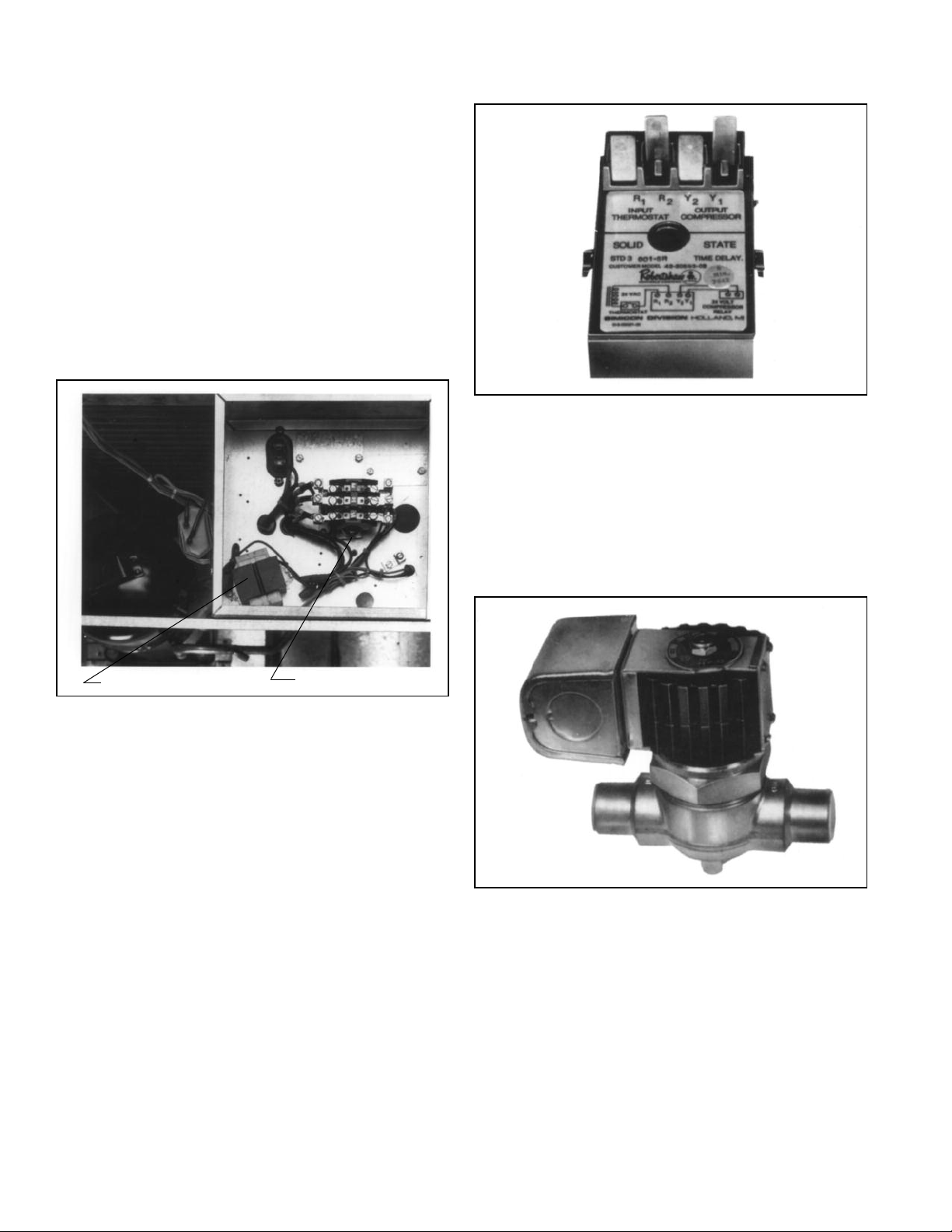
Figure 1: Compressor Contactor
Figure 2: Time Delay Control
Sight Glass — Allows viewing of the refrigerant. Bubbles
may indicate a shortage of refrigerant or a restriction in the
liquid line. The color indicator shows relative moisture saturation of the refrigerant. Its inclusion in the refrigerant piping is
recommended. A minimum of 12 hours after installation is
required before attempting to determine if a moisture condition within the system exists.
Control Transformer
Compressor Contactor
Accessories
Time Delay Control – Prevents restarting of unit for five minutes if shut down for any reason. (See wiring diagram and
schematic in this manual for proper location and installation;
item TDC.)
Liquid Line Solenoid Valve (24V) — Recommended for all
split system applications, to prevent refrigerant migration during off cycles. See wiring connection Page 11. Solenoid to be
located in liquid line close to air handler.
Figure 3: Liquid Line Solenoid Valve
IM 9094
Page 5
Unit Dimensions
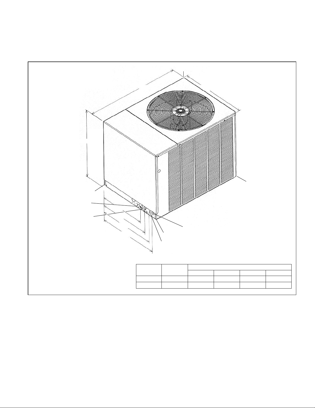
Figure 4: Unit Dimensions and Weights
3253⁄64"
SUCTION
1
LINE 1
LIQUID
LINE 1⁄2"
C
IMPORTANT: THIS UNIT MUST BE
MOUNTED LEVEL IN BOTH DIRECTIONS TO ALLOW WATER TO
43
2
4
⁄64"
D
⁄8"
21
11
24
⁄16"
3
⁄16"
11
26
287⁄16"
⁄16"
HIGH VOLTAGE - 1
B
LOW VOLTAGE -
7
⁄8" HOLE
31
DRAIN FROM THE CONDENSER
1
SECTION AND CONDENSATE PAN.
⁄16"
A
3
⁄4" HOLE
IM 909
Corner Weights (Pounds)
Unit
Model RCS
06E
07E
Total Weight
Lbs. [kg]
266
330 55 [24.95]
Corner Weights, Lbs. [kg]
ABCD
45 [20.41]
66 [29.94]
87 [39.46]
63 [28.58]
73 [33.11]
91 [41.28]
116 [52.62]
5
Page 6
Physical and Electrical Data
Table 1: Physical Data
Model No. RCS- 06 07
Capacity (tons) [kW] 6.5 [22.9] 7.5 [26.4]
Operating Weight (lbs) [kg] 266 [120.7] 330 [149.7]
Shipping Weight (lbs) [kg] 289 [131.1] 353 [160.1]
Compressor:
Quantity 11
Type Scroll
RPM 3500
Refrigerant Charge R-22 Oz. [g] 262 [7428] 262 [7428]
Condenser Fans:
Quantity 11
CFM [l/s] 3500 [1652] 3800 [1793]
Diameter (in) [mm] 24 [610] 24 [610]
Drive Direct
Motor Horsepower [Watts] each 1/3 [249] 1/3 [249]
Type PSC PSC
RPM 1075 1075
Condenser Coil:
Quantity 11
Rows 1
Fins per inch 20 22
Square Feet [m
2
] 22.2 [3] 22.2 [3]
Fins/Tubes Aluminum / Copper
Cabinet:
Finish Power Coat
Sheet Metal Galvanized
Gauge (nominal) Top 20 20
Sides 20 20
Base Rails 14 14
Refrigerant Connection:
Vapor - sweat (in) [mm] 1
Liquid - sweat (in) [mm]
Package Dimensions:
Height (in) [mm] 32.8 [833] 32.8 [833]
Width (in) [mm] 31.1 [789] 31.1 [789]
Length (in) [mm] 43.0 [1092] 43.0 [1092]
1
⁄2 2
1
⁄8 [29] 11⁄8 [29]
1
⁄2 [13]
1
⁄2 [13]
Table 2: Electrical Data
Electrical
Model
Number
RCS
06ECAZ 3-60-208/230 18.6/18.6 156 1.5 25/25 30/30 40/40 22.42 [2.08] 2 3500 [1652] 296 [8392] 266 [120.7] 289 [131.1]
06EDAZ 3-60-460 9 75 1 13 15 20 22.42 [2.08] 2 3500 [1652] 296 [8392] 266 [120.7] 289 [131.1]
06EYAZ 3-60-575 7.4 54 0.8 11 15 15 22.42 [2.08] 2 3500 [1652] 296 [8392] 266 [120.7] 289 [131.1]
07ECAZ 3-60-208/230 25.6/25.6 196 2.2 35/35 45/45 50/50 22.42 [2.08] 2 3800 [1793] 296 [8392] 330 [149.7] 353 [160.1]
07EDAZ 3-60-460 12.8 100 1.3 18 25 30 22.42 [2.08] 2 3800 [1793] 296 [8392] 330 [149.7] 353 [160.1]
07EYAZ 3-60-575 8.7 90 1 12 15 20 22.42 [2.08] 2 3800 [1793] 296 [8392] 330 [149.7] 353 [160.1]
Phase
Frequency (Hz)
Voltage (Volts)
Compressor
Rated Load
Amperes
(RLA)
Locked Rotor
Amperes
(LRA)
Fan Motor
Full Load
Amperes
(FLA)
Minimum
Circuit
Ampacity
Amperes
Fuse or HACR
Circuit Breaker
Minimum
Amperes
Maximum
Amperes
Face Area
Sq. Ft. [m2]
Outdoor Coil
No.
Rows
CFM
[L/s]
Refrig.
Per
Circuit
Oz. [g]
Net
Lbs. [kg]
Weight
Shipping
Lbs. [kg]
6 IM 909
Page 7

Installation
Important Message to Owner
The manufacturer assumes no responsibility for equipment
installed in violation of any code or regulation. The operation
portion of this manual gives instructions as to the service and
care of the unit. It is recommended that the installer go over
he operational portion of this manual with the owner so that
t
there is a full understanding of the equipment and how it is
intended to function.
These instructions should be read and kept for future reference. It is suggested that this booklet be affixed to or adjacent
to the indoor equipment. It is addressed to your dealer and
serviceman, but we highly recommend that you read it—paying particular attention to the section titled “MAINTENANCE.”
Inspection and Handling
Inspect exterior of unit for evidence of rough handling in
shipment. If damage is found, enter claim at once. Unpack
carefully after moving unit to approximate location. Any damage should be reported immediately to the transportation company.
Material in this shipment was inspected at the factory and
released to the common carrier with no known damage.
Order Parts
When reporting shortages or damaged parts, or when ordering
repair parts, give the complete unit model and serial numbers
which are stamped on the Unit Rating Plate.
Standard Items
The condensing unit consists of a completely assembled package which includes a compressor, a condenser coil, fan, fan
motors, outdoor control box, factory wiring, factory tubing
and fittings.
Installation General
The condensing unit should be installed outdoors. It should be
located as near as possible to the evaporator section to keep
connecting refrigerant tubing lengths to a minimum. The unit
must be installed to allow a free air flow to the condenser
coils.
If several units are installed adjacent to each other, care must
be taken to avoid recirculation of air from one condenser to
another. In all installations, adequate space must be provided
for installation and servicing.
Figure 5
Location Considerations
The metal parts of this unit may be subject to rust or deterioration in adverse environmental conditions. This oxidation
could shorten the equipment’s useful life. Salt spray, fog or
mist in seacoast areas, sulphur or chlorine from lawn watering
systems, and various chemical contaminants from industries
such as paper mills and petroleum refineries are especially
corrosive.
If the unit is to be installed in an area where contaminants
are likely to be a problem, give special attention to the
equipment location and exposure.
• Avoid having lawn sprinkler heads spray directly on the
unit cabinet.
• In coastal areas locate the unit on the side of the building
away from the waterfront.
• Shielding by a fence or shrubs may give some protection.
• Frequent washing of the cabinet, fan blade and coil with
fresh water will remove most of the salt or other contaminants that build up on the unit.
• Regular cleaning and waxing of the cabinet with an auto-
mobile polish will provide some protection.
• A liquid cleaner may be used several times a year to
remove matter that will not wash off with water.
Several different types of protective coatings are offered in
some areas. These coatings may provide some benefit, but the
effectiveness of such coating materials cannot be verified by
the equipment manufacturer.
The best protection is frequent cleaning, maintenance and
minimal exposure to contaminants.
DANGER
!
▲▲
These units are designed certified for outdoor installation
only. Installation inside any part of a structure can result in
inadequate unit performance as well as property damage.
Installation inside can also cause recirculation of flue products into the conditioned space resulting in personal injury
or death.
IM 909
7
Page 8

Outside Installation
1 Select a location where external water drainage cannot
ollect around unit.
c
Provide a level slab sufficiently high enough above grade
2
to prevent surface water from entering the unit.
3 Locate the unit to provide proper access for inspection
and servicing.
4 Locate unit where operating sounds will not disturb
owner or neighbors.
5 Locate unit so roof runoff water does not pour directly on
the unit. Provide gutter or other shielding at roof level.
Do not locate unit in an area where excessive snow drifting may occur or accumulate.
6 Select an area which will keep the areas of the vent, air
intake, and A/C condenser fins free and clear of obstructions such as weeds, shrubs, vines, snow, etc. Inform the
user accordingly.
7 To prevent air recirculation, it is recommended that the
unit not be installed under an overhang, but if necessary
allow a minimum of 60 inches above the unit for air
discharge.
8 Condensing units should be set on a solid level founda-
tion. When installed at ground level, the unit should be
placed on a 6 inch cement slab. If the pad is formed at
the installation site, do not pour the pad tight against the
structure, otherwise vibration will be transmitted from
the unit through the pad.
Rooftop Installation
If rooftop installation is required, make certain that the building construction is adequate for the weight of the unit. (Refer
to physical data chart.) Before placing the unit on the roof,
make certain that the nylon rigging slings are of sufficient
length to maintain equilibrium of the unit when lifting. Under
no circumstances should the unit be lifted by only one corner
for rooftop installation.
1 Before locating the unit on the roof, make sure that the
roof structure is adequate to support the weight involved.
(See Electrical & Physical Table in this manual.) THIS
IS VERY IMPORTANT AND THE INSTALLER’S
RESPONSIBILITY.
2 The location of the unit on the roof should be such as to
provide proper access for inspection and servicing.
Figure 6: Suggested Lifting Arrangement
NYLON SLINGS
PREADER BARS
S
Installation of Piping
WARNING
!
▲▲
Do not use oxygen to purge lines or pressure system for
leak test. Oxygen reacts violently with oil, which can cause
an explosion resulting in severe personal injury or death.
Table 3: Refrigerant Piping Data
EQUIVALENT LENGTH (FT.) OF STRAIGHT TYPE “L” TUBING
FOR NON-FERROUS VALVES & FITTINGS (BRAZED)
TUBE SIZE
INCHES
O.D.
1
5
3
7
11⁄8
13⁄8
15⁄8
21⁄8
Once located, the condensing unit is ready to be interconnected with the evaporator using ONLY refrigeration grade dehydrated tubing. The following should be considered when connecting the tubing.
1 Pitch the suction line toward the compressor approxi-
mately 1⁄2 inch every 10 feet to facilitate oil return.
2 It is recommended that the sight glass, filter drier and liq-
uid line solenoid valve be installed in the liquid line just
prior to the evaporator.
3 Silver solder (such as silfos, Easy Flow, etc.) should be
used for all refrigerant joints.
SOLE-
NOID
VALVE
⁄2
⁄8
⁄4
⁄8
ANGLE
VALVE
70
72
75
78
87
102
115
141
24
25
25
28
29
33
34
39
SHORT
RADIUS
ELL
4.7
5.7
6.5
7.8
2.7
3.2
3.8
5.2
LONG
RADIUS
ELL
3.2
3.9
4.5
5.3
1.9
2.2
2.6
3.4
TEE
LINE
FLOW
1.7
2.3
2.9
3.7
5.2
6.9
8.7
12.0
TEE
BRANCH
FLOW
6.6
8.2
9.7
12.0
8.0
10.0
12.0
16.0
IM 9098
Page 9

4 Thoroughly clean all joints before fluxing. DO NOT
SE ACID FLUX.
U
When fluxing, limit the application of paste to the mini-
5
mum and always apply flux to the male portion of the
connection.
6 Suction lines should be insulated to prevent condensate
drip. Use insulation of at least
3
⁄8 inch wall thickness. The
insulation should be installed on the tubing prior to making the sweat connections.
7 Insulate the liquid line whenever the heat pick-up or
transfer can affect the sub-cooling.
8 Care should be taken to avoid transmission of noise or
vibration to building structure.
Size suction lines for no more than 2°F loss which corre-
2
sponds to approximately 3 psig pressure drop.
3 Install sight glass, filter drier and solenoid valve in liquid
line adjacent to evaporator. Filter drier should be between
the condensing unit and sight glass.
4 Pitch all horizontal suction lines downward in the direc-
tion of flow. (
1
⁄2" to 10 ft. run)
5 When making up refrigerant piping, take every precau-
tion to prevent dirt and moisture from entering the piping.
6 Locate the condensing unit and evaporator(s) as close
together as possible to minimize piping runs.
7 Liquid or suction lifts not to exceed 60 ft.
Typical Piping Recommendations
The following will be of help in accomplishing a successful
installation.
1 Size liquid line for no more than 10°F loss which corre-
sponds to approximately 30 psig pressure drop.
Figure 7: Liquid Line Pressure Drop Per 100 Feet
Equivalent Length (Type L Copper Tubing)
NOTES:
1 When evaporator coil is above condenser, the pressure
drop due to vertical lift (.5 PSIG per foot of lift) must be
added to the pressure drop derived from this curve.
2 Size liquid line for no more than 10°F loss (approxi-
mately 30 PSIG total pressure drop).
3 Do not oversize liquid line. Oversized liquid lines add
significantly to the amount of refrigerant required to
charge the system.
4 The maximum recommended velocity with solenoid
valves or other quick closing devices in the liquid line is
300 FPM.
Figure 8: Suction System Capacity Loss in Percent Per
100 Feet Equivalent Length (Type L Copper Tubing)
NOTES:
1 The minimum velocity line (700 fpm) is recommended for
cooling only units with vertical or horizontal run refrigerant lines.
2 For suction pressure drop (PSIG), multiply percent (%)
loss by 1.18.
Table 4: Recommended Vapor and Liquid Line Sizes for
Various Lengths of Run
EQUIVALENT
LENGTH TO
EVAPORATOR
(FEET)
0' to 15'
16' to 50'
51' to 100'
101' to 150'
NOTE: Runs between condenser and evaporator not to exceed 150'
linear length.
LIQUID LINE O.D.
SIZES (INCHES)
091
078
1
1
1
1
⁄2
⁄2
⁄2
⁄2
100
1
⁄2
1
⁄2
1
⁄2
1
⁄2
VAPOR LINE O.D.
SIZES (INCHES)
125
078 091 100 125
5
5
⁄8
5
⁄8
5
⁄8
5
⁄8
11⁄8 11⁄8 13⁄8 13⁄8
⁄8
5
⁄8
11⁄8 11⁄8 13⁄8 15⁄8
5
⁄8
11⁄8 13⁄8 13⁄8 15⁄8
5
⁄8
13⁄8 13⁄8 15⁄8 21⁄8
IM 909
9
Page 10
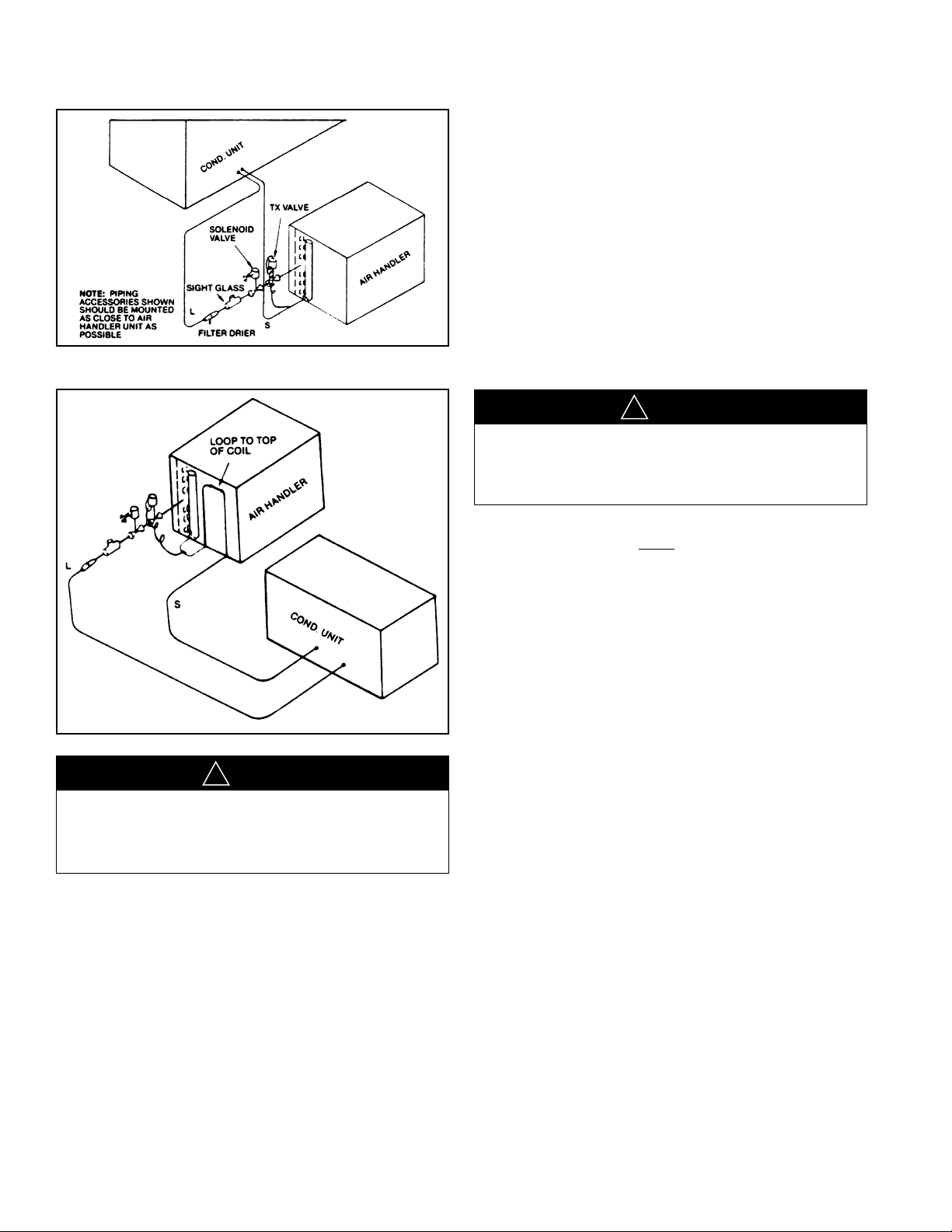
Figure 9: Coil Below Condensing Unit
Figure 10: Coil Above Condensing Unit
It is important that proper electrical power is available at
2
the unit. Voltage should not vary more than 10% from
that stamped on the unit nameplate. On three phase units,
phases must be balanced within 3%.
3 For branch circuit wiring (main power supply to unit dis-
connect), the minimum wire size for the length of run
can be determined from Table 6 using the circuit ampaci-
y found on the unit rating plate. Use the smallest wire
t
size allowable from the unit disconnect to unit.
4 Power wiring should be run in grounded rain-tight con-
duit. See Electrical Data Table on page 6 for unit ampacity and Table 7 for proper wire size. See Table 3 for conduit and hole size based on wire size.
5 A grounding lug is provided in the control box for a
ground wire. Grounding also may be accomplished by
grounding the power line conduit to the unit.
WARNING
!
▲▲
This unit must be permanently grounded. A ground lug is
provided near the contactor for a ground wire. Failure to do
so can cause a fire or electrical shock resulting in property
damage, severe personal injury or death.
IMPORTANT: THIS UNIT IS AP PROVED FOR USE WITH
COPPER CONDUCTORS ONLY
TACTOR.
WARRANTY WILL BE VOIDED IF ALUMINUM WIRE IS CONNECTED TO UNIT CONTACTOR.
CONNECTED TO UNIT CON-
DANGER
!
▲▲
Power supply to unit must be disconnected before making
field connections. To avoid electrical shock, personal injury
or death, be sure to rigorously adhere to field wiring procedures regarding proper lockout and tagout of components.
Wiring
Power Supply
1 All wiring should be made in accordance with the
National Electrical Code. Consult the local power company to determine the availability of sufficient power to
operate the unit. Check the voltage at power supply to
make sure it corresponds to the unit’s RATED VOLTAGE REQUIREMENT. Install a branch circuit disconnect near the rooftop, in accordance with the N.E.C.,
C.E.C. or local codes.
Hook-Up
POWER WIRING MUST BE RUN IN CONDUIT. Conduit
must be run through the connector panel below the service
cover and attached to the bottom of the control box.
If low (extra-low in Canada) voltage control wire is run in
conduit with power supply, Class I insulation is required. If
run separate, Class II is required. Low voltage wiring may be
run through the insulated bushing provided in the 7/8 " hole
in the connector panel then routed to the control box.
10 IM 909
Page 11

Table 5: Conduit and Hole Size
14
CONDUIT SIZE
HOLE SIZE
OTES: 1. DETERMINE REQUIRED WIRE SIZE FROM TABLE 6.
N
2. BOTTOM POWER ENTRY WILL NOT ACCOMMODATE WIRE LARGER THAN #2 AWG (SHADED AREA).
1/2ⴖ
7/8ⴖ
12
1/2ⴖ
7/8ⴖ
10
1/2ⴖ
7/8ⴖ
8
3/4ⴖ
1-31/32ⴖ
6
1ⴖ
1-23/64ⴖ
WIRE SIZE, AWG
4
1ⴖ
1-23/64ⴖ
3
1-1/4ⴖ
1-23/32ⴖ
2
1-1/4ⴖ
1-23/32ⴖ
1
1-1/2ⴖ
1-31/32ⴖ
0
1-1/2ⴖ
1-31/32ⴖ
00
2ⴖ
2-15/32ⴖ
000
2ⴖ
2-15/32ⴖ
Table 6: Branch Circuit Wire Size
COPPER
IRE SIZE—AWG
NIT
U
MCA
0 100 150 200 250 300
5
20 10 86444
25 10 86443
0 8644 32
3
35 8643 21
40 8643 21
5 8432 11/0
4
50 6432 11/0
0 64211/0 2/0
6
70 4321/0 2/0 3/0
80 4311/0 2/0 3/0
0 321/0 2/0 3/0 4/0
9
100 321/0 2/0 3/0 4/0
10 212/0 3/0 4/0 250
1
125 112/0 3/0 4/0 25
W
UPPLY WIRE LENGTH—FEET
S
NOTES:
1 For branch circuit wiring (main power supply to unit
disconnect), the minimum wire size for the length of
run can be determined from this table using the circuit ampacity found on the unit rating plate. From
the unit disconnect to unit, the smallest wire size
allowable in Table 6 may be used, as the disconnect
must be in sight of the unit.
2 Wire size based on 75°C rated wire insulation for
1% voltage drop.
3 For more than 3 conductors in a raceway or cable,
see the N.E.C. (C.E.C. in Canada) for derating the
ampacity of each conductor.
WARNING
!
▲▲
After completion of wiring check all electrical connections,
including factory wiring within the unit, and make sure all
onnections are tight, replace and secure all electrical box
c
covers and access doors before leaving unit or turning on
power to circuit supply unit. Failure to do so can cause a
fire or electrical shock resulting in property damage, personal injury or death.
Internal Wiring
A diagram of the internal wiring of this unit is located on the
inside of control access panel and in this manual. If any of the
original wire as supplied with the unit must be replaced, the
wire gauge and insulation must be same as original wiring.
208 Volt Applications
Transformer is factory wired for 230 volts on 208/230 volt
models and must be changed for 208 volt applications. See
unit wiring diagram for 208 volt wiring.
Thermostat
A single-stage cooling, two-stage heating (if heating is used)
thermostat should be mounted on an inside wall about five
feet above the floor in a location where it will not be affected
by the sun or drafts from open doors or other sources. Install,
level, and after installation check the thermostat calibration
and recalibrate if necessary.
Install the room thermostat in accordance with the instruction
sheet packed in the box with the thermostat.
Figure 11: Typical Field Wiring Connections —
1
6
⁄2 and 71⁄2 Ton
IM 909
Figure 12: Typical Thermostat Wiring
11
Page 12
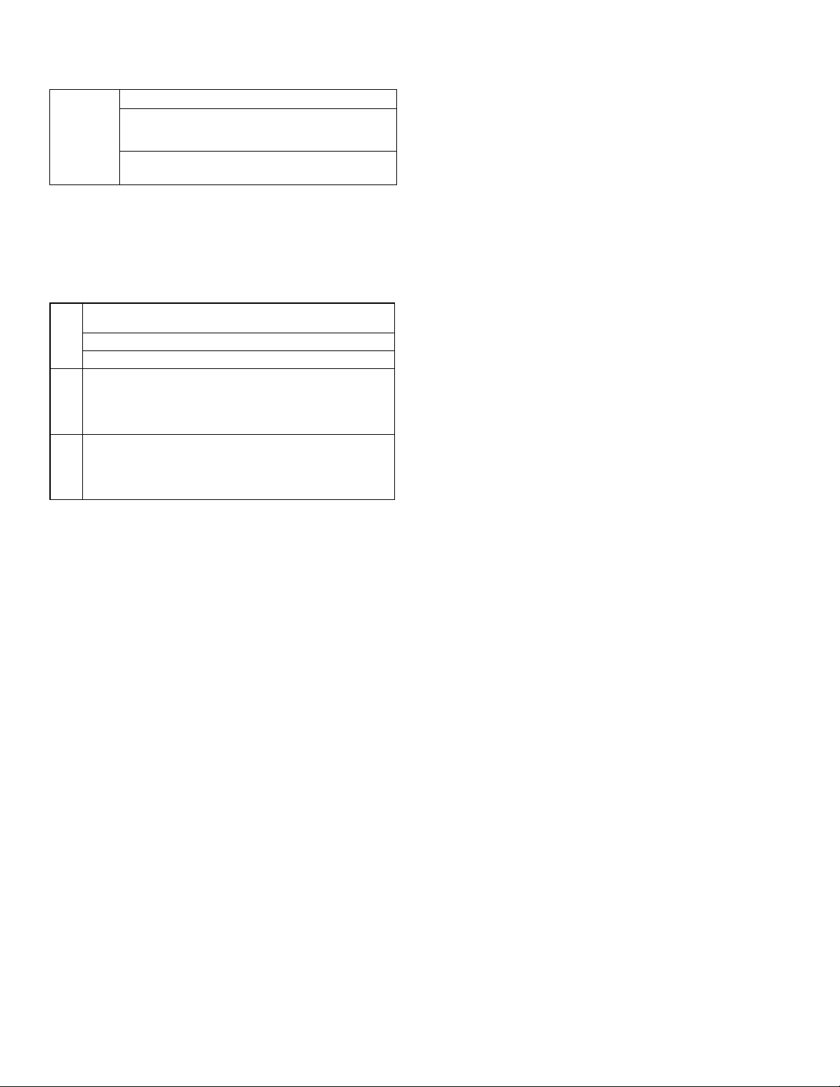
Table 7: Field Wire Size for 24 Volt Thermostat Circuits
SOLID COPPER WIRE - AWG.
3.0 16 14 12 10 10 10
2.5 16 14 12 12 12 10
2.0 18 16 14 12 12 10
Amps
Thermostat Load -
(1) The total wire length is the distance from the unit to the thermostat and back to the unit.
NOTE: DO NOT USE CONTROL WIRING SMALLER THAN
NO. 18 AWG.
Table 8: Copper Wire Size
50 100 150 200 250 300
Length of Run – Feet (1)
(VOLTAGE DROP 1%)
WIRE GAUGE (75°C Insulation)
CIRCUIT
AMPACITY
100 150 200 250 300
40 64 3 2 1
45 43 2 1 1/0
50 43 2 1 1/0
60 42 1 1/0 2/0
70 321/0 2/0 3/0
80 311/0 2/0 3/0
90 2 1/0 2/0 3/0 4/0
100 2 1/0 2/0 3/0 4/0
110 1 2/0 3/0 4/0 250
125 1 2/0 3/0 4/0 250
COPPER
DISTANCE IN FEET
Leak Testing
Pressure the line set and coil through service fittings with dry
nitrogen to 150 psig maximum. Leak test all joints using liquid
detergent. If a leak is found, recover pressure and repair.
Evacuation and Charging
The evacuation of any system component that has been
exposed to atmosphere or lost its charge is essential before
charging. Never attempt to operate a system while it is under
a vacuum.
NOTE – The condensing unit is shipped with a holding
charge of dry nitrogen which must be purged from the unit
before evacuation.
1 Since the condensing unit itself must be evacuated, open
the suction, discharge and liquid shut-off valves.
2 Use a refrigeration type vacuum pump capable of evacu-
ation in the 500 micron range.
3 Connect the vacuum pump to the service manifold
assembly with a pressure gauge that will read 30 inches
vacuum. Connect the service manifold to the suction line
schrader valve port.
With an accurate scale,
4
1
z., set refrigerant tank up so
⁄2 o
its weight can be measured while in a position to charge
liquid. (Unit must be off.) Energize liquid line solenoid
valve by wiring the valve to 24V power supply (or open
by manual stem if applicable).
5 Connect to the liquid shut-off valve port. Shut off tank
nd evacuate the system. The pressure gauge should read
a
at least 29.5" of vacuum.
6 Triple evacuate the system.
7 The refrigerant system will now be free of noncondens-
ables.
8 Remove vacuum pump from 3-way valve.
9 Install refrigerant tank (liquid charging) to service valve.
10 Before tightening, purge tank and service valve hose.
11 Note weight of refrigerant tank.
12 De-energize liquid line solenoid valve. Open refrigerant
tank valve. Allow pressure in tank and unit to equalize.
13 Close off service valve to liquid port and note weight of
refrigerant tank.
14 Position tank for gas charging.
15 Re-wire liquid line solenoid to thermostat control. Close
main disconnect switch and turn thermostat to lowest setting.
16 Charge unit per Tables 10 and 11.
17 Adjust refrigerant charge to obtain pressures indicated in
the temperature/pressure charts on pages 15 and 16.
18 Note weight of refrigerant tank.
19 When system has stabilized, check superheat at the suc-
tion line service valve. The actual line temperature
should be 15° to 25°F higher than the saturation temperature corresponding to the suction pressure. If superheat is
measured at evaporator, the actual line temperature
should be 15° to 20° higher than the saturation temperature corresponding to the suction pressure.
20 Close service ports on suction and liquid valves. Remove
service gauges.
21 Replace service port caps and valve stem caps. These
caps must be replaced to prevent leaks.
22 Record total charge quantity on rating plate.
IM 90912
Page 13
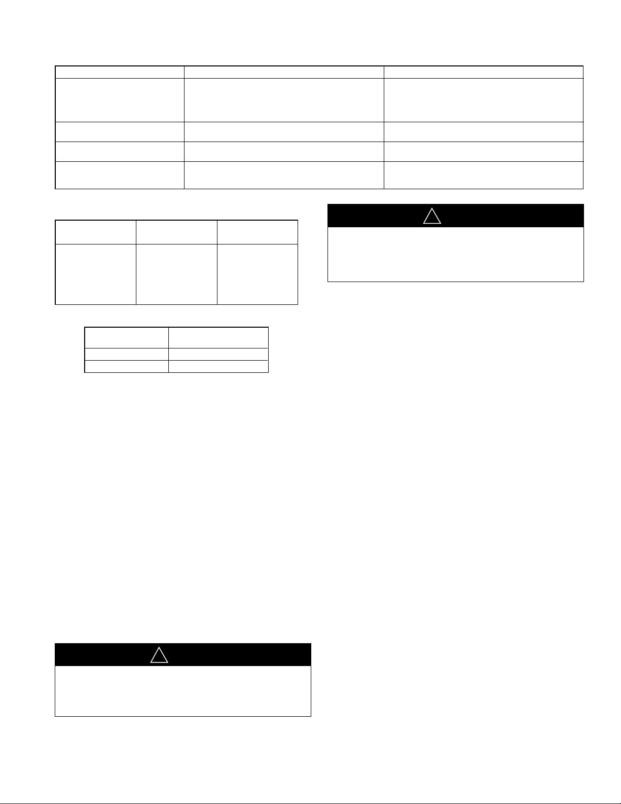
Table 9: Charging Hints
SYMPTOM
High head pressure a. Air flow to or from condenser restricted or a. Remove obstruction, relocate condensing unit,
Low head pressure a. Short of refrigerant. a. Check for leak, add charge.
Low vapor & a. Short of refrigerant. a. Check for leak—add refrigerant.
hot compressor
Excessive sweating a. Low indoor airflow a. Increase speed of air handler blower or reduce
Table 10: Required Ozs. R-22 Charge Per Ft. of Tubing
TUBE SIZE
O.D.
1
⁄2 1.20 —
5
⁄8 1.86 —
11⁄8 2.67 .06
11⁄8 — .15
13⁄8 — .22
15⁄8 — .29
21⁄8 — .43
Table 11: Basic System Charge (with 0 Feet of tubing)
Unit
Model
RCS-06 262 [7428]
RCS-07 262 [7428]
LIQUID
TUBE
dirty condenser if necessary clean condenser.
b. Faulty condenser fan or motor. b. Replace.
c. Overcharge of refrigerant c. Reduce charge.
d. Air in system. d. Evacuate and recharge.
b. Low evaporator air flow. b. Increase blower speed, check filters.
b. Excess refrigerant b. Slowly reduce charge.
Basic System
Charge, Oz. [g]
POSSIBLE CAUSE REMEDY
restriction—replace air filter.
DANGER
!
SUCTION
TUBE
Power supply to unit must be disconnected before making
field connections. To avoid electrical shock, personal injury
or death, be sure to rigorously adhere to field wiring procedures regarding proper lockout and tagout of components.
▲▲
Contactor
The contactor is an electrical switch which operates the compressor and condenser fans. Its 24 volt coil is activated either
directly or indirectly by the room thermostat.
High Pressure Switch (HPC)
Opens the contactor (24 volt) circuit on high refrigerant pressure—Manual Reset—check for cause of tripping before putting unit back in service.
System Operating Information
Advise the Customer
1 Except for the mounting platform, keep all combustible
articles three feet from the unit and exhaust system.
2 IMPORTANT: Replace all blower doors and compartment
cover after servicing the unit. Do not operate the unit
without all panels and doors securely in place.
3 Do not allow snow or other debris to accumulate in the
vicinity of the unit.
4 For maximum efficiency, the condenser coil must be
kept clean. Periodic inspections, depending on local
conditions are recommended. If it is necessary to clean
the condenser coil, use a common garden hose.
5 Never operate the unit without filters installed in the air
handler.
6 If a compressor crankcase heater is used, it must be
turned on 12 to 24 hours prior to starting the compressor.
DANGER
!
▲▲
Label all wires prior to disconnection when servicing controls. Wiring errors can cause improper and dangerous
operation resulting in fire, electrical shock, property damage, personal injury or death.
Low Pressure Switch (LPC)
Acts as safety against loss of refrigerant and low evaporator
temperatures.
Replacement Parts
To find your local McQuay Certified Parts Distributor, go to
www.mcquay.com and select Parts Locator.
Troubleshooting
Refer to Figure 13 for determining cause of unit problems.
Charging
See Figures 14 and 15 for proper charging information.
IM 909
13
Page 14

Figure 13
Cooling Trouble Shooting Chart
DANGER
!
▲▲
Disconnect all power to unit before servicing. Contactor may break only one side. Failure to shut off power can cause electrical
shock resulting in personal injury or death.
SYMPTOM POSSIBLE CAUSE REMEDY
Unit will not run • Power off or loose electrical connection • Check for correct voltage at compressor contactor in control
• Thermostat out of calibration-set too high • Reset
• Failed contactor • Check for 24 volts at contactor coil - replace if contacts are
• Blown fuses • Replace fuses
• Transformer defective • Check wiring-replace transformer
• High pressure control open (if provided) • Reset-also see high head pressure remedy-The high pressure
• Interconnecting low voltage wiring damaged • Replace thermostat wiring
Condenser fan runs, compressor • Loose connection • Check for correct voltage at compressor -
doesn’t check & tighten all connections
• Compressor stuck, grounded or open motor winding • Wait at least 2 hours for overload to reset.
open internal overload. If still open, replace the compressor.
• Low voltage condition • Add start kit components
Insufficient cooling • Improperly sized unit • Recalculate load
• Improper airflow • Check - should be approximately 400 CFM per ton.
• Incorrect refrigerant charge • Charge per procedure attached to unit service panel.
• Air, non-condensibles or moisture in system • Recover refrigerant, evacuate & recharge, add filter drier
• Incorrect voltage • At compressor terminals, voltage must be within 10% of rating
Compressor short cycles • Incorrect voltage • At compressor terminals, voltage must be ± 10% of
• Defective overload protector • Replace - check for correct voltage
• Refrigerant undercharge • Add refrigerant
Registers sweat • Low evaporator airflow • Increase speed of blower or reduce restriction - replace air
box
open
control opens at 450 PSIG
At compressor terminals, voltage must be within 10% of rating
plate volts when unit is operating.
plate volts when unit is operating.
nameplate marking when unit is operating.
filter
High head pressure- • Restriction in liquid line, expansion device or filter drier • Remove or replace defective component
low vapor pressures • Flow check piston size too small • Change to correct size piston
• Incorrect capillary tubes • Change coil assembly
High head pressure-high or • Dirty condenser coil • Clean coil
normal vapor pressure - • Refrigerant overcharge • Correct system charge
Cooling mode • Condenser fan not running • Repair or replace
• Air or non-condensibles in system • Recover refrigerant, evacuate & recharge
Low head pressure-high vapor • Defective Compressor valves • Replace compressor
pressures • Incorrect capillary tubes • Replace coil assembly
Low vapor pressure - • Low evaporator airflow • Increase speed of blower or reduce restriction - replace air
cool compressor - filter
iced evaporator coil • Operating below 65°F outdoors • Add Low Ambient Kit
• Moisture in system • Recover refrigerant - evacuate & recharge - add filter drier
High vapor pressure • Excessive load • Recheck load calculation
• Defective compressor • Replace
Fluctuating head & vapor • Air or non-condensibles in system • Recover refrigerant, evacuate & recharge
pressures
Gurgle or pulsing noise at • Air or non-condensibles in system • Recover refrigerant, evacuate & recharge
expansion device or liquid line
IM 90914
Page 15

Figure 14
RAWE-079
SYSTEM CHARGE CHART – REFRIGERANT 22
61⁄2 TON CONDENSER
CAUTION: 1. RETURN AIR TEMPERATURE MUST BE WITHIN COMFORT CONDITIONS
BEFORE FINAL REFRIGERANT CHECK.
INSTRUCTIONS: 1. MEASURE PRESSURE AT COMPRESSOR SUCTION AND LIQUID VALVE.
2
. MEASURE OUTDOOR AMBIENT TO UNIT.
3. PLACE (X) ON CHART WHERE SUCTION AND LIQUID INTERSECT.
4. IF (X) IS BELOW OUTDOOR AMBIENT LINE, ADD CHARGE AND REPEAT
STEP 3.
5. IF (X) IS ABOVE OUTDOOR AMBIENT LINE, RECOVER EXCESS CHARGE
AND REPEAT STEP 3.
*
WITH CONDENSER FANS OPERATING, MAY REQUIRE
JUMPERING OF HEAD PRESSURE CONTROL.
REFRIGERANT REQUIRED: 262 OZ. WITH 0 FT. OF SUCTION & LIQUID LINE.
SUCTION PRESSURE (PSIG)
LIQUID PRESSURE (PSIG)
OUTDOOR AMBIENT (°F. DB)
RCS-06E
SYSTEM CHARGE CHART – REFRIGERANT 22
61⁄2 TON CONDENSER
IM 909
15
Page 16

RAWE-091
SYSTEM CHARGE CHART – REFRIGERANT 22
71⁄2 TON CONDENSER WITH 10 TON EVAPORATOR
CAUTION: 1. RETURN AIR TEMPERATURE MUST BE WITHIN COMFORT CONDITIONS
BEFORE FINAL REFRIGERANT CHECK.
I
NSTRUCTIONS: 1. MEASURE PRESSURE AT COMPRESSOR SUCTION AND LIQUID VALVE.
2. MEASURE OUTDOOR AMBIENT TO UNIT.
3. PLACE (X) ON CHART WHERE SUCTION AND LIQUID INTERSECT.
4. IF (X) IS BELOW OUTDOOR AMBIENT LINE, ADD CHARGE AND REPEAT
S
TEP 3.
5. IF (X) IS ABOVE OUTDOOR AMBIENT LINE, RECOVER EXCESS CHARGE
AND REPEAT STEP 3.
*
WITH CONDENSER FANS OPERATING, MAY REQUIRE
JUMPERING OF HEAD PRESSURE CONTROL.
REFRIGERANT REQUIRED: 294 OZ. WITH 0 FT. OF SUCTION & LIQUID LINE.
SUCTION PRESSURE (PSIG)
LIQUID PRESSURE (PSIG)
OUTDOOR AMBIENT (°F. DB)
Figure 15
RCS-07E
SYSTEM CHARGE CHART – REFRIGERANT 22
71⁄2 TON CONDENSER WITH 10 TON EVAPORATOR
IM 90916
Page 17
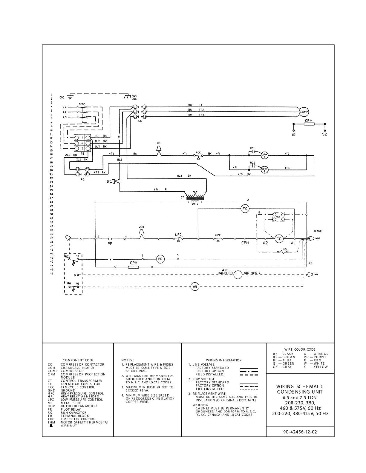
Figure 16: Wiring Diagram 61⁄2 and 71⁄2 Ton Units
IM 909
17
Page 18

Service and Warranty Procedure
Service and Warranty Procedure
Replacement Parts
When contacting McQuay for service or replacement parts,
provide the model number, serial number, and unit part
number of the unit as stamped on the serial plate attached to
t
he unit. For questions regarding wiring diagrams, provide the
n
umber on the specific diagram. If replacement parts are
required, include the date of unit installation, the date of
failure, an explanation of the malfunction, and a description of
the replacement parts required.
Scroll Compressor
All McQuay Rooftop products include a first-year parts only
warranty. The warranty period extends 12 months from startup
or 18 months from date of shipment, whichever comes first.
Labor to install these parts is not included with this warranty.
Compressors are considered a part and are included in this
standard warranty.
All Compressors
Replacement compressors for McQuay Rooftop Units can be
obtained from the McQuay Service Parts department.
The decision to replace the failed portion of the compressor
tandem, as opposed to replacing the entire tandem, must be
decided based on the following.
1 In warranty: Warranty only covers replacement of the failed
portion of the tandem.
2 Out of warranty: The customer decides whether to replace
the entire tandem or just a portion.
3 Some equipment may include the extended 2nd - 5th year
compressor warranty option.
Order the replacement compressor through the McQuay Parts
Department (Minneapolis).
1 Contact the McQuay Parts Department for compressor
availability.
2 Send a completed parts order form to the McQuay Parts
D
epartment.
3 The Parts Department processes the order and the
compressors are shipped from our Dayton, OH warehouse
via ground transportation. If next-day air is required,
indicate this on the parts order form and a freight charge
will be billed to your account. Air freight costs are not
covered under the McQuay warranty.
4 After the failed compressor is replaced, return it to McQuay
International with a Return Goods Tag attached, which you
will receive in the mail. It must be attached to the
compressor. The Return Goods Tag has instructions on
where to send the compressor. If the compressor is not
returned, you will be billed for the replacement compressor.
5 Consideration may be given at this time to a compressor
teardown analysis, depending on the history of failures.
In-Warranty Return Material Procedure
Material other than compressors may not be returned except by
permission of authorized factory service personnel of McQuay
International at Minneapolis, Minnesota.
A “return goods” tag will be sent to be included with the
returned material. Enter the information as called for on the tag
in order to expedite handling at out factories and issuance of
credits. All parts shall be returned to the factory designated on
the return goods tag, transportation charges prepaid.
The return of the part does not constitute an order for
replacement. A purchase order for the replacement part must
be entered through your nearest McQuay representative. The
order should include the component's part number and
description and the model and serial numbers of the unit
involved.
If it is determined that the failure of the returned part is due to
faulty material or workmanship within the standard warranty
period, credit will be issued on the customer's purchase order.
IM 90918
Page 19

RCS Condensing Unit Equipment Warranty Registration Form
To comply with the terms of McQuay Warranty, complete and return this Equipment
Warranty Registration Form within 10 days to McQuay, Warranty Department
Check, test, and start procedure for RoofPak roof mounted air conditioners
w
ith or without heat recovery and roof mounted air handlers.
Job Name: __________________________________________________________ McQuay G.O. No.: ________________
I
nstallation address: __________________________________________________________________________________
C
ity: _______________________________________________________________________________ State: _________
P
urchasing contractor: ________________________________________________________________________________
City:________________________________________________________________________________ State: _________
Name of person doing start-up (print)____________________________________________________________________
C
ompany name ____________________________________________________________________
A
ddress __________________________________________________________________________
City/State/Zip ______________________________________________________________________
Unit model number:___________________________________________________ Unit serial number: ______________
Compressor #1 model number: ________________________________________ Serial number: __________________
Compressor #2 model number: ________________________________________ Serial number: __________________
Circle Yes or No. If not applicable to the type of unit, circle N/A.
I. INITIAL CHECK
A. Is any shipping damage visible? . . . . . . . . . . . . . . . . . . . . . . . . . . . . . . . . . . . . . . . . . . . . . . . . . . . . . . . . . . . . . . . . . . .
Yes No N/A
B. Tightened all setscrews?. . . . . . . . . . . . . . . . . . . . . . . . . . . . . . . . . . . . . . . . . . . . . . . . . . . . . . . . . . . . . . . . . . . . . . . . .
Yes No N/A
C. Have the shipping spacers been removed from the compressor springs and have the neoprene spacers been
installed on each compressor mounting bolt? (Only applies to 115C–135C units with compressor spring isolators.)
Yes No N/A
D. Electrical service corresponds to unit nameplate? . . . . . . . . . . . . . . . . . . . . . . . . . . . . . . . . . . . . . . . . . . . . . . . . . . . . .
Yes No N/A
Volts __________
Hertz __________ Phase __________
E. Is the main disconnect adequately fused and are fuses installed?. . . . . . . . . . . . . . . . . . . . . . . . . . . . . . . . . . . . . . . . . Yes No N/A
F. Are crankcase heaters operating, and have they been operating 24 hours prior to start-up? . . . . . . . . . . . . . . . . . . . .
Yes No N/A
G. Are all electrical power connections tight? (Check compressor electrical box.) . . . . . . . . . . . . . . . . . . . . . . . . . . . . . . .
Yes No N/A
H. Has the field piping been piped per ASHRAE recommendations?: . . . . . . . . . . . . . . . . . . . . . . . . . . . . . . . . . . . . . . . .
Yes No N/A
II. START-UP COMPRESSOR OPERATION
A. Has each circuit been field leak tested?
Circuit 1. . . . . . . . . . . . . . . . . . . . . . . . . . . . . . . . . . . . . . . . . . . . . . . . . . . . . . . . . . . . . . . . . . . . . . . . . . . . . . . . . . . . . . Yes No N/A
Circuit 2. . . . . . . . . . . . . . . . . . . . . . . . . . . . . . . . . . . . . . . . . . . . . . . . . . . . . . . . . . . . . . . . . . . . . . . . . . . . . . . . . . . . . .
Yes No N/A
B. Refrigerant charge per circuit:
Circuit 1 ________ Circuit 2 ________
C. Backseat discharge, suction (sizes 115C –135C only), and liquid line valves? . . . . . . . . . . . . . . . . . . . . . . . . . . . . . . . Yes No N/A
D. Are compressors rotating in the right direction? . . . . . . . . . . . . . . . . . . . . . . . . . . . . . . . . . . . . . . . . . . . . . . . . . . . . . . .
Yes No N/A
E. Do condenser fans rotate in the right direction? . . . . . . . . . . . . . . . . . . . . . . . . . . . . . . . . . . . . . . . . . . . . . . . . . . . . . . .
Yes No N/A
F. Ambient temperature:
____________ °F
G. Oil safety control time delay (sizes 115C–135C only): Compressor #1 sec. _______ Compressor #2 sec. _______
H. Compressor lockout timers function? . . . . . . . . . . . . . . . . . . . . . . . . . . . . . . . . . . . . . . . . . . . . . . . . . . . . . . . . . . . . . . .
Yes No N/A
I. FanTrol functions:
TC12 ________ TC13 ________
TC14 ________
J. Part winding start time functions (sizes 115C–135C only):
Compressor: TD1 __________ TD2 __________ TD3 __________ TD4 __________
K. Does unit start up and perform per sequence of operation?. . . . . . . . . . . . . . . . . . . . . . . . . . . . . . . . . . . . . . . . . . . . . . Yes No N/A
IM 909
19
Page 20

RCS Condensing Unit Equipment Warranty Registration Form
E
quipment Warranty Registration Form (continued)
I
II. PERFORMANCE DATA
A. Compressor voltage across each phase: L1–2________ V L2–3 ________ V L1–3 _______ V
B
. Compressor amperage of fully loaded compressor:
C
ompressor #1: Phase 1 ________ Phase 2 ________ Phase 3 ________
C
ompressor #2: Phase 1 ________ Phase 2 ________ Phase 3 ________
C. Low pressure cut-out: Circuit 1 psig Circuit 2 psig
L
ow pressure cut-in: Circuit 1 psig Circuit 2 psig
D. High pressure cut-out: Circuit 1 psig Circuit 2 psig
E. Discharge pressure, one compressor: Circuit 1 psig Circuit 2 psig
F
. Discharge pressure, fully loaded: Circuit 1 psig Circuit 2 psig
G
. Suction pressure, one compressor: Circuit 1 psig Circuit 2 psig
S
uction pressure, fully loaded: Circuit 1 psig Circuit 2 psig
Circuit 1 psi g Circuit 2 psig
L
iquid press, fully loaded (at liquid line
s
hutoff valve):
Liquid temperature, fully loaded: Circuit 1 psig Circuit 2 psig
Circuit 1 Circuit 2
H. Suction line temperature: _______________________________ °F °F
I. Superheat: _______________________________ °F °F
J. Subcooling: _______________________________ °F °F
K. Is the liquid in the liquid line sightglass clear and dry? . . . . . . . . . . . .
L. At what suction pressure does the hot gas bypass Circuit 1 _________ psi g Circuit 2 _________ psig
valve open?
M.
Record discharge air temperature at discharge of the air handler:
°F
N. Are all control lines secure to prevent excessive vibration and wear? . . . . . . . . . . . . . . . . . . . . . . . . . . . . . . . . . . . . . . Yes No N/A
O. Are all gauges shut off and valve caps and packings tight after start-up? . . . . . . . . . . . . . . . . . . . . . . . . . . . . . . . . . . . Yes No N/A
Signature: __________________________________________________________ Startup date:
Please see the following page “Quality Assurance Survey Report” and list any additional comments that could affect the operation of this unit; e.g.,
shipping damage, failed components, adverse installation applications, etc. If additional comment space is needed, write the comment(s) on a
separate sheet, attach it to the Survey Report and return it to the Warranty Department with the above completed Warranty Registration form.
RETURN COMPLETED EQUIPMENT WARRANTY REGISTRATION FORM TO:
McQuay International Warranty Department, 13600 Industrial Park Boulevard, Minneapolis, MN 55441
. . . . . . . . . . . . . . . . . . . . . . . . . . . . . . . . . . . . Yes No N/A
.
_________________________________
20 IM 909
Page 21

Quality Assurance Survey Report
Is any shipping damage visible? . . . . . . . . . . . . . . . . . . . . .
Location on unit ___________________________________________________________________________
.
How would you rate the overall appearance of the product; i.e., paint, fin damage, etc.?
Excellent Good Fair Poor
Did all sections of the unit fit together properly?
Did the cabinet have any air leakage? . . . . . . . . . . . . . . . . . . . . . .
Location on unit ___________________________________________________________________________
Were there any refrigerant leaks? . . . . . . . . . . . . . . . . . . . . . . .
Shipping Workmanship Design
Does the refrigerant piping have excessive vibration?. . . . .
Location on unit ___________________________________________________________________________
Did all of the electrical controls function at start-up? . . . . . .
Comments _______________________________________________________________________________
Did the labeling and schematics provide adequate information?
How would you rate the serviceability of the product?
Excellent Good Fair Poor
1 How would you rate the overall quality of the product?
Excellent Good Fair Poor
11. How does the quality of McQuay products rank in relation to competitive products?
Excellent Good Fair Poor
Comments:
Please list any additional comments which could affect the operation of this unit; i.e., shipping damage, failed components, adverse installation
applications, etc. If additional comment space is needed, write the comment(s) on a separate sheet, attach the sheet to this completed Quality
Assurance Survey Report, and return it to the Warranty Department with the completed preceding “Equipment Warranty Registration Form”.
RETURN COMPLETED QUALITY ASSURANCE SURVEY REPORT TO:
McQuay International Warranty Department, 13600 Industrial Park Boulevard, Minneapolis, MN 55441
. . . . . . . . . . .
.
. . . . . . . . . . . . . . . . . . . . . . . . . . . . . . . . . . . Ye s No N/A
.
. . . . . .
. . . . . . . . . . . . . . . . . . . . . . . . . . . . . . . . . . . . Yes No N/A
.
. . . . . . . . . . .
.
. . . . . . . . . . . . . . . . . . . . . . . . . . . . . . . . . . . Ye s No N/A
.
. . . . . . . . . . .
. . . . . . . . . . . . . . . . . . . . . . . . . . . . . . . . . . . . Yes No N/A
.
. . . . . . . . . . .
.
. . . . . . . . . . . . . . . . . . . . . . . . . . . . . . . . . . . Ye s No N/A
.
. . . . . . . . . . .
. . . . . . . . . . . . . . . . . . . . . . . . . . . . . . . . . . . . Yes No N/A
.
. . . . . . . .
. . . . . . . . . . . . . . . . . . . . . . . . . . . . . . . . . . . . Yes No N/A
.
. . . . . .
. . .
To whom it may concern:
Please review the items below upon receiving and installing our product. Mark N/A on any item that does not apply to the product.
J
ob Name: _____________________________________________________ McQuay G.O. no. __________________________________
I
nstallation Address: ___________________________________________________________________________________________________
City: __________________________________________________________ State: __________________________________________
Purchasing Contractor: _________________________________________________________________________________________________
C
ity: ____________________________________________________ State: __________________________________________
1.
2
.
3
.
4.
5
.
6.
7.
8.
9.
0.
IM 909
21
Page 22

22 IM 909
Page 23

IM 909
23
Page 24

McQuay Training and Development
Now that you have made an investment in modern, efficient McQuay equipment, its care should be a high priority.
For training information on all McQuay HVAC products, please visit us at www.mcquay.com and click on training, or
call 540-248-9646 and ask for the Training Department.
Warranty
All McQuay equipment is sold pursuant to its standard terms and conditions of sale, including Limited Product
Warranty. Consult your local McQuay Representative for warranty details. Refer to Form 933-43285Y. To find your
local McQuay Representative, go to www.mcquay.com.
This document contains the most current product information as of this printing. For the most up-to-date product
information, please go to www.mcquay.com.
© 2008 McQuay International • www.mcquay.com • 800-432-1342
24 IM 909
 Loading...