

Page 1

Replacement Parts List No. 700013700
Revision U 07/12
Roofpak
Applied Rooftop Units
RPS, RDT, RFS, RCS
Sizes 045 - 079 Tons
Vintage D
R410a
To find your Daikin McQuay Parts distributor, call 1-800-377-2787 or visit www.DaikinMcQuay.com
Page 2

Contents
Parts List Revision History ................................................................................................................................... 5
Nomenclature ...................................................................................................................................................6- 13
Electrical Legend ...........................................................................................................................................14- 17
Section A1- Outdoor/Return Air Section
Notes .............................................................................................................................................................. 18
100% Outside Air Damper with Hood- No Return Air Plenum ....................................................................... 19
100% Outside Air Damper Detail w/ACT3 ..................................................................................................... 20
0 - 30% Outside Air Section w/ ACT3 ............................................................................................................ 21
0- 100% Economizer Section with Barometric Exhaust Damper- Units without Return Air Fans .................. 22
0- 100% Economizer Section with Barometric Exhaust Damper- Units with 40” Return Air Fans ................. 23
0- 100% Economizer Section with Prop Exhaust Fan & Damper................................................................... 24
0 - 100% Economizer Damper w/ ACT3- Diagrams ....................................................................................... 25
0 - 100% Economizer Damper w/ ACT3- Components .................................................................................. 26
Return Air Plenum Isolation Damper w/ Actuator ACT6................................................................................. 27
Prop Exhaust Fan & Damper Detail ......................................................................................................... 28, 29
Design Flow Detail ......................................................................................................................................... 30
Return Air Fan Detail- Fan Mounts ................................................................................................................ 31
Return Air Fan Detail ...................................................................................................................................... 32
Return Air Fan Motors .................................................................................................................................... 33
Section Mounted Controls- OAE, RAE, LT11, S11, REC11 .......................................................................... 34
Ebtron Sensor Detail ...................................................................................................................................... 35
Section A2- Outdoor/Return/Heat Recovery Air Section
Notes .............................................................................................................................................................. 36
Cabinet Gaskets, Doors, Hardware, Exhaust Hoods ..................................................................................... 37
Base Components, Hood, Dampers .............................................................................................................. 38
40” Return Fan Detail ............................................................................................................................... 39, 40
Low Leak Damper Detail ............................................................................................................................... 41
Bypass “L” Type Damper Detail ..................................................................................................................... 42
Heat Recovery— Enthalpy— Wheel Detail .................................................................................................... 43
Wheel, Motor, Drive Components, Seals ....................................................................................................... 43
AFD60 Frost Protection Inverter .................................................................................................................... 43
Section Mounted Controls- OAE, RAE, RAT, EAT, LAT ................................................................................ 44
Section Mounted Controls- SD2, HUM1, LT11, S11, REC11 ........................................................................ 45
Section B- Draw-Thru Filter/Blank Section
Notes .............................................................................................................................................................. 46
Section Mounted Controls- PC5, LT13, S13, REC13 .................................................................................... 46
Filters ....................................................................................................................................................... 47, 48
Air Blender Section Components ................................................................................................................... 48
Section C- Draw-Thru Blank Access Section or Separate Inverter Section
Notes .............................................................................................................................................................. 49
Section D- Draw-Thru Cooling Section
Notes .............................................................................................................................................................. 50
24” Section, Small Face Coils ........................................................................................................................ 51
48” Section, Large Face Coils ........................................................................................................................ 51
Section E- 48” Spacer Section & Section E- Draw-Thru Heat Section
Notes .............................................................................................................................................................. 52
Section Mounted Controls- LT18, REC18, S18- Section Mounted Light........................................................ 52
Hot Water or Steam Coil Heat, Mixing Valves and Actuator (VM1) ............................................................... 53
Section F- Supply Air Section
Notes .............................................................................................................................................................. 54
Forward Curved Fans- Low Pressure- FCLP ................................................................................................ 55
Forward Curved Fans- High Pressure- FCMP ............................................................................................... 56
Air Foil Fan- Double Width ............................................................................................................................. 57
Air Foil Fan- Single Width- RDT Units ............................................................................................................ 58
RoofPak Singlezone; RPS,RDT,RFS,RCS 045-079 “D” Rev. U 07/12 RPL 700013700 / Page 2
Page 3

Contents
Continued
Section F- Supply Air Section, Continued
Fan Mounts- 27” Forward Curved Fan ........................................................................................................... 59
Fan Mounts- 30” Forward Curved Fan ........................................................................................................... 60
Fan Mounts- 33” Forward Curved Fan ........................................................................................................... 61
Fan Mounts- 27” Airfoil Double Width Fan ..................................................................................................... 62
Fan Mounts- 30” Airfoil Double Width Fan ..................................................................................................... 63
Fan Mounts- 33” Airfoil Double Width Fan ..................................................................................................... 64
Fan Mounts- 40” AFSW- RDT Units ............................................................................................................... 65
Fan Mounts- 44” AFSW- RDT Units ............................................................................................................... 66
Supply Air Fan Motors .................................................................................................................................... 67
Belt Guard ...................................................................................................................................................... 68
Inverters & Inverter Bypass Control Box
Motor HP 2 - 5 ............................................................................................................................................ 69
Motor HP 7.5 - 25 ................................................................................................................................. 70, 71
Motor HP 30 - 50 .................................................................................................................................. 72, 73
Inverters ............................................................................................................................................... 74- 77
Line Reactors ............................................................................................................................................. 78
Section Mounted Controls- PC7, HL22, LT10, S10, REC10, UV Lights ........................................................ 79
Section Mounted Controls- MATS, EFTS, SATS, DATS, OATS, SD1 ........................................................... 80
Section Mounted Controls- SCB- Split Junction Box- TB25,TB27,TB28,PB10,PB9,PB20,PB19 .................. 81
Section G- Blow-Thru Heat Section
Notes .............................................................................................................................................................. 82
Option 1: Blank Compartment
Diffuser ....................................................................................................................................................... 82
Option 2: Hot Water or Steam Coil Heat
Mixing Valves and Actuator (VM1) ............................................................................................................. 83
Heaters, Diffusers, Hi Limit Cutouts HL1-20, 31-50 ................................................................................... 84
Option 3: Electric Heat
Heaters, Diffusers, Hi Limit Cutouts HL1-20, 31-50 ................................................................................... 85
Electric Heat Control Box ..................................................................................................................... 86- 90
Option 4- Gas Heat
Vestibules, Heat Exchangers and Primary Components- 200 or 250 MBH Furnaces .............................. 91
Vestibules, Heat Exchangers and Primary Components- 320, 400, 500, 640, 650, 790, 800, 1000 ......... 92
Modulating Burner ................................................................................................................................ 93- 95
Hi Turn Down Burner ...........................................................................................................................96- 99
Modulating Burner Controls
No Controls- Diagram ......................................................................................................................... 100
No Controls- Components ................................................................................................................... 101
MicroTech III Controls ......................................................................................................................... 102
Hi Turn Down Burner Controls
No Controls- Diagram ......................................................................................................................... 103
No Controls- Components ................................................................................................................... 104
MicroTech III Controls ......................................................................................................................... 105
Gas Train- Inlet ................................................................................................................................106- 108
Gas Train- Controls: GV1,GV2, GV3, GV4, GV5, GV6, VM1 .......................................................... 109- 111
Gas Train- Outlet ..................................................................................................................................... 112
Gas Train- Damper Linkage ..................................................................................................................... 113
Cabinet Doors, Gasketing, Hardware, and Flue Box Mounting ....................................................... 114, 115
Section H- Blow-Thru Heat Blank Access Section
Notes ............................................................................................................................................................ 116
Section Mounted Controls- LT19, REC19, S19- Section Mounted Light...................................................... 116
RoofPak Singlezone; RPS,RDT,RFS,RCS 045-079 “D” Rev. U 07/12 RPL 700013700 / Page 3
Page 4

Contents
Continued
Section I- Blow-Thru Cooling Section
Notes ............................................................................................................................................................ 117
Section Mounted Controls- LT16, S16, REC16 ........................................................................................... 117
Section J- Final Filter Section
Notes ............................................................................................................................................................ 118
Section Mounted Controls- HL23, PC6 ........................................................................................................ 118
Filters ........................................................................................................................................................... 119
Section K- Discharge Plenum Section- RPS or RFS
Notes ............................................................................................................................................................ 120
Section Mounted Controls- OAT, DAT, SD1 ................................................................................................ 120
Damper Assembly- w/ Actuator ACT5 ......................................................................................................... 121
Section L- Out-of-Airstream Blank Access Section
Notes ............................................................................................................................................................ 122
Section Mounted Controls- LT20, REC20, S20 ........................................................................................... 122
Section M- Condenser Section
Notes ............................................................................................................................................................ 123
Condenser Fan Deck Assembly- 045D thru 068D: C47= 1, 2 ............................................................ 124, 125
Condenser Fan Deck Assembly- 070D thru 079D: C47= 1, 2 ............................................................ 126, 127
Quiet Fan Assembly: C47= 3, 4 .................................................................................................................. 128
Compressors & Compressor Components
Unit Size 045D ......................................................................................................................................... 129
Unit Size 050D, 051D .............................................................................................................................. 130
Unit Size 060D thru 063D ........................................................................................................................ 131
Unit Size 068D ......................................................................................................................................... 132
Unit Size 070D thru 079D ........................................................................................................................ 133
Condenser Control Box- RCS Only ...................................................................................................... 134- 137
RCS Pressure Manifolds- PC13, PC23, HP1, HP2, LP1, LP2, SPTRL ............................................... 138, 139
RPS/RDT Pressure Controls Box- AFD11, AFD21, LR11, LR21, LP1, LP2, HP1, HP2 ..................... 140, 141
McQuay Supplied Line Voltage Box- T6, DS6, FU6A, FU6B, FU6C............................................................ 142
Section N- Main Control Box
Notes ............................................................................................................................................................ 143
Control Panel - No Controls ................................................................................................................ 144, 145
Control Panel- MicroTech III Units with Controller ...............................................................................146- 148
Power Panel ......................................................................................................................................... 149- 170
Section O- Refrigeration Tubing
Notes ............................................................................................................................................................ 171
Refrigeration Tubing Diagram ...................................................................................................................... 171
Valves, Filter Driers, Sight Glasses ...................................................................................................... 172, 173
Hot Gas Reheat ........................................................................................................................................... 174
RoofPak Singlezone; RPS,RDT,RFS,RCS 045-079 “D” Rev. U 07/12 RPL 700013700 / Page 4
Page 5

Parts List Revision History
Rev. Date Description
A- F 10/11 Archived Revisions A thru F.
G 09/10 Updated Cover and Master page with new title showing 079 Large Condenser. Range changed from 045-075 to 045-
079. Added in Large Condenser sizes and p/ns on various pages. Updated TOC, page headers, and parts tables
with new sizes. New RPS size units include: 051, 063, 071 & 079. P/Ns ref: EPS_5229 Rev J.
Page 6: Changed note for Nominal capacity to an explanation of tonnage rating.
Page 12: Added Quiet Fan (Code 47= 3 or 4) to Nomenclature.
Page 34, 44, 80, 120, 147: Changed Sensor p/n 193414600 to 193414602.
Page 39: Added Wheel p/n 010255226, Bearings 020648654 & 300043930, Shaft p/n 010288112 to Ref #10.
Page 48: Corrected Header for Air Blender Section and added section notation to TOC.
Page 57: Added circle and line to aid in identifying the discharge side of the fan housing.
Page 77: Changed 575V p/ns: 349956738 to 193456302, 349956739 to 193456303, 349956741 to 193456304,
349956742 to 193456305, 349956743 to 193456306, 349956744 to 193456307, & 349956745 to 193456308.
Page 123: Re-wrote Code 47 Note to add Quiet Fan options.
Page 125: Deleted invalid Prop p/n 060013101. Updated table with Large Condenser sizes & p/ns.
Page 126: Added “Code 47= 1, 2” to page header.
Page 127: Deleted invalid Prop p/n 060013101. Added “Code 47= 1, 2” to page header
Page 128: (New)- Added page with “Quiet Fan Assembly” p/ns & instruction drawing. Repaginated document and
updated TOC.
Page 130 (Old) 131 (New): Changed CC Heater Ref #145 from 113108903 to 113108603.
Page 131 (Old) 132 (New): Changed CC Heater Ref #145 from 113108903 to 113108603.
Page 132 (Old) 133 (New): Changed CC Heater Ref #145 from 112056401 to 113108903.
Page 137 thru 140 (Old) 138 thru 141 (New): Added Speedtrol Pressure Switch Harness p/n 403586601.
Page 170- 172 (Old) 171- 173 (New)- Created Section O for Refrigeration Tubing. Updated TOC.
Page 170 (Old) 171 (New): Re-wrote Code 48 Note to clarify information. Added Code 03 information.
Page 173 (New): Added additional page for new Large Condenser size p/ns. Repaginated document and updated TOC.
Page 172 (Old) 174 (New): Added instruction drawing and assigned bubble numbers to p/n table. Updated p/n table
with Large Condenser sizes. Added footnote #1 regarding HGRH located on Circuit #2.
H 11/10 Page 41: Replaced Ref #122 ACT 3 actuator p/n 1131395601 with 113139501. Added footnote #1.
Page 147: Replaced COM p/ns: 193408101 with 090016709; 193408201 with 090016711; 193408202 with
090016712, & 193408301 with 090016710.
I 01/11 Page 147: P/ns for LonWorks DAC & LonWorks SCC were reversed. DAC= 090016712, SCC= 090016711.
J 02/11 Page 147:
193410305, 193410406 to 193410306, 193410407 to 193410307 & 193410408 to 193410308.
K 05/11 Page 125: Deleted qty of 1pc. Vandal Guard 403909506 for Size 068.
L 06/11 Page 28: Re-arranged/updated Ref #6 Bub & P/ns. Added 6B Blade p/n 300044027, 6C Shaft p/n 300044028,
6D bearing p/n 300044029, 6F Bushing p/n 000804000. Changed 6I motor p/ns from 065820200 &
046514600 to 300046887 & 300046251.
M 07/11 Page 125, 127: Added new Ref #111 Condenser Motor p/n 500552601 and updated descriptions. Added footnotes # 2-4.
N 08/11 Page 167: Corrected misaligned formatting on table.
O 10/11
Page 132: Changed CC Heater Ref #145 to 113108903 from 113108603.
Page 133: Changed CC Heater Ref #145 to 112056401 from 113108903.
P 12/11
Page 174:
Q 01/12 Page 9: For Code 13 (Air Flow controls), deleted unused code “8”.
Page 147: Added After 9/11 SPS1, 2 p/ns 910117463 & 910117462. Deleted unused sensor SPS3- Code 13=8 is invalid.
R 03/12 Cover, Pg. 5: Updated to current Daikin McQuay logo format.
Page 104: Changed Ref# 25 from 073300801 to 073300803. Changed relay p/n 193454702 to 193454703 3 places.
Added p/ns for R23A relay 349934764 & adapter 349964702.
S 06/12 Various: Changed “McQuay Parts” to “Daikin McQuay Parts”.
Page 74: VTAC9 Inverter p/n 098861454 is 5HP ONLY. Deleted invalid information.
Page 75: Added footnote for 550 Keypad Display p/n.
Page 92: Changed header from “500/650” to “500/640”.
Page 172, 173: Added RCS HGBP kit 193330721. Added footnote #4.
T 07/12 Page 79: Changed PC7 from 060015801 to Switch 910115489 & retrofit kit 910122413. Changed Fitting p/n from
049763002 to 910122414. Added tootnote #1 & updated drawing.
U 07/12 Page 131, 132: Updated tandem compressor information to replacement singles. Rewrote footnote.
Page 133: Added Cir #2 079D cmpr p/ns: 113091901, 113091902, & 113091904.
Page 131: Changed CC Heater Ref #145 to 113108903 from 113108603.
Page 147: Changed SPS1-3 p/ns 049545012 to 910124529 & 049545013 to 910124528. Added footnote #2.
Changed Terminal block p/ns: 193410402 to 193410302, 193410403 to 193410303, 193410405 to
Added piping detail drawing, updated Bub #s, Added MGHRH p/ns-Valve 404031101 & Coil 404031101.
McQuay International, 13600 Industrial Park Blvd., P.O. Box 1551, Minneapolis, MN 55440 (763) 553-5330
RoofPak Singlezone; RPS,RDT,RFS,RCS 045-079 “D” Rev. U 07/12 RPL 700013700 / Page 5
Page 6

Nomenclature
Model Number- Dataplate
R PS 060 D S L
R = RoofPak
PS = Heating, Mechanical Cooling; Single Zone Unit
FS = Heating, Future Mechanical Cooling; Single Zone Unit
CS = Condensing Section Only; Single Zone Unit
DT = Draw Through Heating, Mechanical Cooling
Eg. 060 = 60 Nominal Tons of Capacity
Unit Configuration
Nominal Capacity (tons)
Design Vintage
Heat Medium
A = Natural Gas
E = Electric
S = Steam
W = Hot Water
Y = None (Cooling Only)
Cooling Coil Size
S = Standard (Low Airflow)
L = Large (High Airflow)
Nomenclature
Serial Number
FBO U 09 05 12345
Plant Identification
FBO = Faribault, MN
U= Unit
Year of Manufacture
08= 2008
09= 2009
10= 2010
etc.
RoofPak Singlezone; RPS,RDT,RFS,RCS 045-079 “D” Rev. U 07/12 RPL 700013700 / Page 6
Serial Number
(Build sequence)
Month of Manufacture
01= January
02= February
03= March
04= April
05= May
06= June
07= July
08= August
09= September
10= October
11= November
12= December
Page 7

Nomenclature
Continued
Unit Model Number- Complete
RPS 062D S A Y 1 EU D 27 AL P1 LE 3 2 A 3 CK K120 BB FE 40B1 JEY 1250A Y AB S CYYS 4Z104D
Code 03 04 05 06 07 08 09 10 11 12 13 14 15 16 17 18 19 20 21 22 23 24 25 26 27 28
YYYYYY BBBBBB 30A1 QEY 1250A 100SSB YYYY YYYYYY YYYYYY B B BB Y 4 MY R 1 1 1 H D YY1AAA
29 30 31 32 33 34 35 36 37 38 39 40 41 42 43 44 45 46 47 48 49 50-54
Unit Section Layout Examples
A=
Return Air/Outside Air/
Heat Recovery/Prop Exhaust
Section
B, C, D, E=
Draw-Thru Section
F=
Supply Fan
Section
G, H, I=
Blow-Thru Section
RPS
J=
Final
Filter
K=
Discharge
Plenum
L=
Out-of Air- Stream
Blank Access
M=
Condenser Section
B C F G
A
Prop Exhaust Draw Thru
A
Heat Recovery Draw Thru Heat Recovery Blow Thru
A
D
B C F G
D
H J
H J
RFS
B C F G
D
K M
K M
H
J K
B C F G
A
D
Return Air Fan Draw Thru
A
B C F
H
H J
G
RCS
J K M
I
M
K M
Return Air Fan Draw Thru
RDT
A
RoofPak Singlezone; RPS,RDT,RFS,RCS 045-079 “D” Rev. U 07/12 RPL 700013700 / Page 7
B C F
With Prop Exhaust With Return Air Fan
D
E
M
A
B C F
D
E
M
Page 8
Prop Exhaust
(not shown)
Inverters, Line Reactors
& Manual Bypass
Heat Control
Electric
Panel
Nomenclature
Continued
Supply Air Section
N
Main Control
Panel
Fantrol/
Speedtrol Box
Code Applications
Controls Locations
Condenser
Section
Condenser Control Panel
(RCS Only)
Condenser Control Panel
(RCS Only)
Unit Model Codes that Pertain: 03, 05, 06, 07, 51- 54
General Options
Section A- Return/Outside Air/Heat Recovery Options
Unit Model Codes that Pertain: 14, 15, 19, 20, 21, 22, 23, 24, 48, 49
Section B- Filter
Unit Model Codes that Pertain: 25
Section C- Draw-Thru Blank Access
Unit Model Codes that Pertain: 26
Section D- Draw-Thru Cooling Section
Unit Model Codes that Pertain: 27, 28, 29
Section E- Draw-Thru Heating/Blank Section
Unit Model Codes that Pertain: 30
Section F- Supply Fan Options
Unit Model Codes that Pertain: 14, 15, 31, 32, 33, 48, 49
Section G= Blow-Thru Heat/Blank
Unit Model Codes that Pertain: 04, 34
Section H= Blow-Thru Blank Access
Unit Model Codes that Pertain: 38
Section I- Blow-Thru Coil Sections
Unit Model Codes that Pertain: 35, 36, 37
Section J- Final Filter Section
Unit Model Codes that Pertain: 39
Section K- Discharge Plenum Section
Unit Model Codes that Pertain: 40
Section L- Blank Compartment Section- Out of Airstream
Unit Model Codes that Pertain: 41
Section M- Condenser Section
Unit Model Codes that Pertain: 42, 43, 44, 45, 47, 48
Section N- Main Control Panel
Unit Model Codes that Pertain: 8, 9, 10, 11, 12, 18
Auxiliary Controls/ Remote Sensors
Unit Model Codes that Pertain: 13, 16, 17
Tubing Options
Unit Model Codes that Pertain: 46
RoofPak Singlezone; RPS,RDT,RFS,RCS 045-079 “D” Rev. U 07/12 RPL 700013700 / Page 8
Page 9

Nomenclature
Continued
Code 01= Unit Type
RPS= Rooftop Packaged Singlezone Unit
RFS= Rooftop Future Refrigeration Singlezone Unit
RCS= Rooftop Condensing Unit
RDT= Rooftop Packaged Drawthru Singlezone Unit
Code 02= Unit Size
Nominal Tonnage= 045, 050, 060, 062, 068, 070, 075
Code 03= Cooling Coil
S= Small L= Large
Code 04= Heat Type
A= Natural Gas E= Electric
S= Steam W= Hot Water
Y= None
Code 05= Unit Split
C= Condenser F= Fan/Heat Y= None
Code 06= Insulation and Liners
1= 1”, 3/4# with liners on doors
2= 1½”, 1½# with solid liners on doors & ceilings
3= 1½”, 1½# with perforated liners in plenums, solid elsewhere
4= 1½”, 1½# with solid liners on doors, ceilings and floors
5= 1½”, 1½# with perforated liners in plenums, solid elsewhere
(including floors)
6= 1½”, 1½# with SS Solid Liners on doors, ceilings and floors
Code 07= Approval Agency Listing
CC, CD, CY= ETL Canada
EU, EY= ETL/MEA- USA
YY= None
Code 08= Main Control Box Location
D= Discharge Plenum (RPS/RFS) or Standard (RCS)
F= Supply Fan Section (RDT)
Code 09= Unit Voltage
12= 208/60/3 29= 230/60/3
27= 460/60/3 37= 575/60/3
Code 10= Starting Option
AL= Across- The- Line
Code 11= Field Power Connection and Disconnect
P1= Single Power Block: Complete Unit
Q1= Two Power Blocks: EH/Balance of Unit
A2= One, thru-the-door Disconnect: Complete Unit
C2= Two, thru-the-door Disconnects: SAF&RAF&CB/Balance of Unit
B2= Two, thru-the-door Disconnects: EHB/Balance of Unit
D2= Three thru-the-door Disc.: EH/SAF&RAF&CB/Balance of Unit
Code 12= Temperature Controls
MicroTech III Controls
LE= LonMark w/ Discharge Air Temp. Ctl.
LF= LonMark w/ Space or Zone Ctl.
BE= BACNet w/MSTP w/ Discharge Air Temp. Ctl.
BF= BACNet w/MSTP w/ Space or Zone Ctl.
EE= BACNet w/Ethernet w/ Discharge Air Temp. Ctl.
EF= BACNet w/Ethernet w/ Space or Zone Ctl.
SE= Standalone w/ Discharge Air Temp. Ctl.
SF= Standalone w/ Space or Zone Ctl.
No Controls
YM= No Temperature Controls w/floating point control
YC= No Temp. Ctls. w/6-9 volt DC modulating gas heat actuator
Code 13= Air Flow Controls
Y= None
1= 1 duct sensor
2= 2 duct sensors
3= 1 duct and 1 space sensor
4= 1 space sensor
5= Duct Hi Limit (DHL) sensor
Code 14= Inverters
Y= None
Separate Section
1= SA Fan only w/bypass 2= SA & RA Fans w/bypass
4= RA only w/bypass
No Separate Section
3= SA Fan only w/bypass 5= SA & RA Fans w/bypass
6= SA Fan only no bypass 7= SA & RA Fans no bypass
8= RA Fan only w/bypass 9= RA Fan only no bypass
Code 15= Inlet Vane/Damper Actuators or Inverter Type
Y= None A= ABB Inverter
G= Graham Inverter
R= Reliance Inverter
S= McQuay MD2, MD3, or MD6
F= Field Installed Inverter controlled by MTech
Code16= Smoke Detectors
Y= None 1= Return Air Fan Section
2= Supply Air Fan Section 3= 1 (RA) + 2 (SA)
Code 17= Misc. Aux. Controls
C G
Y= None
F= Freezestat (Steam or HW Heat only)
P= Phase Failure
G= Ground Fault Protection
L= Line Reactors (Inverter w/ separate section only)
A= Freezestat & Phase Failure (Steam or HW Heat only)
B= Freezestat & Ground Fault (Steam or HW Heat only)
C= Phase Failure & Ground Fault
D= Freezestat, Phase Failure & Ground Fault (Steam or HW Heat only)
E= Freezestat & Line Reactors (ST/HW Heat & Inverter w/separate section only)
H= Phase Failure & LIne Reactors (Inverter w/ separate section only)
J= Freezestat, P.F. & Line Reactors (ST/HW Heat & Inverter w/separate section only)
K= Ground Fault, Phase Failure & Line Reactors (Inverter w/ separate section only)
1= UV Lights
2= UV Lights + F
3= UV Lights + P
4= UV Lights + L
5= UV Lights + A
6= UV Lights + E
7= UV Lights + H
8= UV Lights + J
C= Differential Enthalpy
Y= None (includes mechanical enthalpy)
Code 18= Misc. Controls/ Unit Length
YYYY= None
W___= Wireless Modem (___= Air Handler Length [in.])
M___= Phone Modem (___= Air Handler Length [in.])
K___= Remote Keypad (___= Air Handler Length [in.])
U___= Unit Powered Receptacle (___= Air Handler Length [in.])
V___= K + U (___= Air Handler Length [in.])
Code 19= Return Air Plenum
YY= None (no return air section)
BY= Bottom Return
HY= Back Return
SY= Side (opp. drive) Return
BE= Bottom Return w/Iso. Damper w/ Actuator
BB= Bottom Return w/Burglar Bars
RoofPak Singlezone; RPS,RDT,RFS,RCS 045-079 “D” Rev. U 07/12 RPL 700013700 / Page 9
Page 10

Nomenclature
Continued
Code 20= Outdoor Air Options
YY= None
AE= 100% Outside air damper w/hood & actuator
AY= 100% Outside air damper w/hood/no actuator
BE= 0- 30% Outdoor air section w/actuator
BY= 0- 30% Outdoor air section w/o actuator
DE= 0- 100% Econ. w/barometric exhaust damper w/act.
DY= 0- 100% Econ. w/barometric exhaust damper w/o act.
EE= 0- 100% Econ. w/power closure exhaust damper w/act.
EY= 0- 100% Econ. w/power closure exhaust damper w/o act.
HE= 0- 100% Econ. w/prop exhaust damper w/act.
HY= 0- 100% Econ. w/prop exhaust damper w/o act.
FE= same as DE + Design Flow
FY= same as DY + Design Flow
GE= same as EE + Design Flow
GY= same as EY + Design Flow
JE= same as HE + Design Flow
JY= same as HY + Design Flow
KE= same as DE + Ebtron Sensor
KY= same as DY + Ebtron Sensor
LE= same as EE + Ebtron Sensor
LY= same as EY + Ebtron Sensor
ME= same as HE + Ebtron Sensor
MY= same as HY + Ebtron Sensor
3E= Energy Recovery Economizer, Low CFM- 6”
4E= Energy Recovery Economizer, Low CFM- 12”
5E= Energy Recovery Economizer, High CFM- 6”
6E= Energy Recovery Economizer, High CFM- 12”
Code 21= Return Air Fan
YYYY= No Return Air Fan
40B()= 40” Airfoil Single Width
()= isolator type:
1= rubber in-shear
2= spring
3= spring w/seismic restraints
Code 22= Return Air Fan Motor
YYY= No Return Fan
J K Y
G= 2.0 HP
H= 3.0 HP
J= 5.0 HP
K= 7.5 HP
Code 23= Return Air Fan Drive Selection
YYYY= No Return Air Fan
_ _ _ _ A
Required
RPM
Code 24= Exhaust Fans or Frost Protection
Y= None
1= 1 Prop Exhaust Fan w/ Hood
2= 2 Prop Exhaust Fans w/ Hood
F= Heat Recovery Frost Protection Inverter
Always Y
E= High Eff. ODP motor
H= High Eff. Totally-Enclosed
J= Premium Eff. ODP
K= Premium Eff. Totally- Encl.
L= 10.0 HP Q= 30.0 HP
M= 15.0 HP
N= 20.0 HP
P= 25.0 HP
(prop exhaust option is
always J [5.0 HP])
Service Factor/Pitch Type
A= Std. SF/Fixed Pitch
B= 150% SF/Fixed Pitch
C= Std. SF/Variable Pitch
D= 150% SF/Variable Pitch
Code 25= Draw-Thru Filter Section
AB= Angular/30% Throwaway
AC= Angular/30%/Intersept
AY= Angular/No Media
DB= Angular w/LO CFM Blender/30% Throwaway
DC= Angular w/LO CFM Blender/30%/Intersept
DY= Angular w/LO CFM Blender/No Media
EB= Angular w/HI CFM Blender/30% Throwaway
EC= Angular w/HI CFM Blender/30%/Intersept
EY= Angular w/HI CFM Blender/No Media
FB= Flat/ 30%Throwaway
FC= Flat/30%/Intersept
FD= Flat/65% Cartridge
FE= Flat/95% Cartridge
FG= Flat/95% Cartridge/Intersept
FY= Flat/Rack Only
GB= Flat w/LO CFM Blender/ 30%Throwaway
GC= Flat w/LO CFM Blender/30%/Intersept
GD= Flat w/LO CFM Blender/65% Cartridge
GE= Flat w/LO CFM Blender/95% Cartridge
GG= Flat w/LO CFM Blender/95% Cartridge/Intersept
GY= Flat w/LO CFM Blender/Rack Only
HB= Flat w/HI CFM Blender/30%Throwaway
HC= Flat w/HI CFM Blender/30%/Intersept
HD= Flat w/HI CFM Blender/65% Cartridge
HE= Flat w/HI CFM Blender/95% Cartridge
HG= Flat w/HI CFM Blender/95% Cartridge/ Intersept
HY= Flat w/HI CFM Blender/Rack Only
LD= Large Staggered/65% Cartridge
LE= Large Staggered/95% Cartridge
LG= Large Staggered/95% Cartridge/Intersept
LY= Large Staggered/Rack Only
SD= Staggered/65% Cartridge
SE= Staggered/95% Cartridge
SG= Staggered/95% Cartridge/Intersept
SY= Staggered/Rack Only
TD= Staggered w/LO CFM Blender/65% Cartridge
TE= Staggered w/LO CFM Blender/95% Cartridge
TG= Staggered w/LO CFM Blender/95% Cartridge/Intersept
TY= Staggered w/LO CFM Blender/Rack Only
VD= Staggered w/HI CFM Blender/65% Cartridge
VE= Staggered w/HI CFM Blender/95% Cartridge
VG= Staggered w/HI CFM Blender/95% Cartridge/Intersept
VY= Staggered w/HI CFM Blender/Rack Only
BY= Blank 24” Section- less filters and rack
CY= Blank 48” Section- less filters and rack
Code 26= Blank Draw-thru Section
Y= None
S= Blank 48” Section
Code 27= Draw-Thru Drain Pan/Cooling Coil Section
YYYY= None
CYYS= Cooling coil section w/stainless steel sloped drain pan
CYYY= Cooling coil section w/galvanized steel sloped drain pan
Code 28= Draw-Thru Cooling Coil
YYYYYY= No Cooling Coil
4Z 08 3 H
3= 3 Row 5= 5 Row
4= 4 Row
08= 8 Fins-per-inch
10= 10 Fins-per-inch
12= 12 Fins-per-inch
4Z= Type 4EZ
D= Lanced Aluminum
RoofPak Singlezone; RPS,RDT,RFS,RCS 045-079 “D” Rev. U 07/12 RPL 700013700 / Page 10
Page 11

Nomenclature
Continued
Code 29= Draw-Thru Heating Coil
YYYYYY= No Heating Coil
Code 30= Draw-Thru Heating Section (RDT only)
or Blank Spacer Section
YYYYYY= No Heating Section
BBBBBB= Blank 48” Section
Hydronic Heat (RDT only)
W22 J 3 E
E= Electric Actuator
Y= Less Actuator
2= 2 Way Steam Valve Y= No Valve
3= 3 Way HW Valve
E= 1¼” Valve Pkg. H= 2½” Valve Pkg.
F= 1½” Valve Pkg. J= 3.0” Valve Pkg.
G= 2.0” Valve Pkg. Y= No Valve Pkg.
S11= 5JA0601H (6FPI, 1 Row 5J Steam Coil)
S12= 5JA1201H (12FPI, 1 Row 5J Steam Coil)
S13= 5JA0602C (6FPI, 2 Row 5J Steam Coil)
S14= 5JA1202C (12FPI, 2 Row 5JSteam Coil)
W11= 5WH0901H (9FPI, 1 Row 5WH HW Coil)
W22= 5WS0902C (9FPI, 2 Row 5WS HW Coil)
Electric Heat (RDT only)
E020 1 Y
Always ‘Y’
1= 1 Stage 2= 2 Stages
4= 4 Stages 6= 6 Stages
E020= 20 KW Heater E200= 200 KW Heater
E040= 40 KW Heater E240= 240 KW Heater
E060= 60 KW Heater
E080= 80 KW Heater
E100= 100 KW Heater
E120= 120 KW Heater
E160= 160 KW Heater
Code 31= Supply Air Fan
27A()= 27” Airfoil Double Width, w/o vanes
27V()= 27” Airfoil Double Width, w/vanes
27F()= 27” Forward Curved, LP
27M()= 27”Forward Curved, MP
30A()= 30” Airfoil Double Width, w/o vanes
30V()= 30” Airfoil Double Width, w/vanes
30F()= 30” Forward Curved, LP
30M()= 30”Forward Curved, MP
33A()= 33” Airfoil Double Width, w/o vanes
33V()= 33” Airfoil Double Width, w/vanes
33F()= 33” Forward Curved, LP
33M()= 33”Forward Curved, MP
40B()= 40” Airfoil Single Width, w/o vanes (RDT only)
40W()= 40” Airfoil Single Width, w/vanes (RDT only)
44B()= 44” Airfoil Single Width, w/o vanes (RDT only)
44W()= 44” Airfoil Single Width, w/vanes (RDT only)
()= Fan Isolators: 1= RIS; 2= Spring;
3= Spring w/Seismic Snubbers
Code 32= Supply Air Fan Motor
K A Y
Always Y
H= High Eff. Totally-Enclosed
E= High Eff. ODP motor
J= Premium Eff. ODP Motor
K= Premium Eff. Totally-Enclosed
H= 3.0 HP M= 15.0 HP R= 40.0 HP
J= 5.0 HP N= 20.0 HP S= 50.0 HP
K= 7.5 HP P= 25.0 HP
L= 10.0 HP Q= 30.0 HP
Code 33= Supply Air Fan Drive Selection
_ _ _ _ A
Service Factor/Pitch Type
Required
RPM
A= Std. SF/Fixed Pitch
B= 150% SF/Fixed Pitch
C= Std. SF/Variable Pitch
D= 150% SF/Variable Pitch
Code 34= Blow Thru Heat Section
YYYYYY= No section, cooling only
BBBBBB= Blank 48” section, no heat, cooling only
Gas Heat Breakdown:
020 S S C
A= Low CFM Baffle Position D= Extra High CFM
B= Medium CFM Baffle Position Y= None
C= High CFM Baffle Position
E= Modulating Burner/Maximum gas pressure= 0.5 psi
R= Modulating Burner/with H.P. Regulator Range= 2-3 psi
S= Modulating Burner/with H.P. Regulator Range= 5-10 psi
H= Hi Turn Down Burner 20:1
T= Hi Turn Down Burner 20:1/with H.P. Regulator Range= 2-3 psi
U= Hi Turn Down Burner 20:1/with H.P. Regulator Range= 5-10 psi
S= Stainless Steel Heat Exchanger
MBH (in 10’s)
ex. 020= 200 MBH [020,025,032,040,050,064,065,079,080,100]
Hydronic Heat Breakdown:
W22 J 3 E
E= Electric Actuator
Y= Less Actuator
2= 2 Way Steam Valve Y= No Valve
3= 3 Way HW Valve
E= 1¼” Valve Pkg. H= 2½” Valve Pkg.
F= 1½” Valve Pkg. J= 3.0” Valve Pkg.
G= 2.0” Valve Pkg. Y= No Valve Pkg.
S11= 5JA0601H (6FPI, 1 Row 5J Steam Coil)
S12= 5JA1201H (12FPI, 1 Row 5J Steam Coil)
S13= 5JA0602C (6FPI, 2 Row 5J Steam Coil)
S14= 5JA1202C (12FPI, 2 Row 5JSteam Coil)
W11= 5WH0901H (9FPI, 1 Row 5WH HW Coil)
W22= 5WS0902C (9FPI, 2 Row 5WS HW Coil)
Electric Heat Breakdown:
E020 1 Y
Always ‘Y’
1= 1 Stage 2= 2 Stages
4= 4 Stages 6= 6 Stages
E020= 20 KW Heater E120= 120 KW Heater
E040= 40 KW Heater E160= 160 KW Heater
E060= 60 KW Heater E200= 200 KW Heater
E080= 80 KW Heater E240= 240 KW Heater
E100= 100 KW Heater
Code 35= Draw-Thru Drain Pan/Cooling/Heating Coil Section
YYYY= None
CYYS= Cooling coil section w/stainless steel drain pan
CYYY= Cooling coil section w/galvanized steel drain pan
DYYS= Stainless Steel Drain pan only (48” blank section)
DYYY= Galvanized Steel Drain pan only (48” blank section)
Code 36= Draw-Thru Cooling Coil
YYYYYY= No Cooling Coil
4Z 08 3 H
3= 3 Row 5= 5 Row
4= 4 Row
08= 8 Fins-per-inch
10= 10 Fins-per-inch
12= 12 Fins-per-inch
4Z= Type 4EZ
H= Aluminum Fin D= Lanced Aluminum
C= Copper Fin
RoofPak Singlezone; RPS,RDT,RFS,RCS 045-079 “D” Rev. U 07/12 RPL 700013700 / Page 11
Page 12

Nomenclature
Code 37= Draw-Thru Heating Coil
YYYYYY= No Heating Coil
Code 38= Blow-Thru Blank Access Section
Y= None- No Section
B= Blank Section after Heat Section- 48” section
Code 39= Final Filter Section
Y= None
A= Flat filter section, 95% cartridge, 24/24”
B= Staggered filter section, 95% cartridge, 24/48”
C= Blank- 24/24” section
D= Blank- 24/48” section
E= Flat filter section, 95% cartridge, 24/24” with Intersept
F= Staggered filter section, 95% cartridge, 24/48” with Intersept
Code 40= Discharge Plenum
BY= Bottom Discharge
BB= Bottom Discharge w/Burglar Bars
BE= Bottom Discharge w/Discharge Damper (VAV)
FY= Front Discharge (RFS only)
SY= LH Side Discharge
HY= LH Side Discharge (RDT only)
GY= Bottom Discharge (RDT only)
GB= Bottom Discharge w/Burglar Bars (RDT only)
Code 41= Blank Compartment Section- Out of Airstream
Y= None- no selection required
1= 48/24” Blank Section only- out of airstream with light
2= 48” Blank Section only- out of airstream with light
Continued
Code 48= IBC Seismic Constr/Power Factor Capacitors
H= Modulating Gas Reheat
I= Seismic Construction - Code 21 and/or 31 must be ***1 or ***3
K= Modulating Hot Gas Reheat and Seismic Construction
Y= None
Code 49= Fan Section Options
A= SA Fan Belt Guard
B= SA Fan Section Light
C= A + B
D= SA & RA Fan Belt Guard
E= SA & RA Fan Section Light
F= D + E
Y= None
Code 50= Miscellaneous
YY= None
XX= Special
Code 51= Packaging
Codes 52, 53, 54= Warranty Information
Code 42= Compressor Capacity Control
4= 4 steps (045- 068) 6= 6 steps (070, 075)
Code 43= Condenser Options
MG= Micro Channel Coil w/ Coil Guards
MS= Micro Channel Coil w/ Seal Tite Conduits
MB= Micro Channel Coil w/ Coil Guards + Seal Tite Conduits
MY= Micro Channel Coil
PG= Electrofin Coated Micro Channel Coil w/ Coil Guards
PS= Electrofin Coated Micro Channel Coil w/ Seal Tite Conduits
PB= PG + PS
PY= Electrofin Coated Micro Channel Coil
Code 44= Compressor Type
R= Scroll 410a
Code 45= Compressor Isolation
1= Resilient Rubber-in-Shear 2= Spring isolation Y= None
Code 46= Piping Options
1= Hot Gas Bypass, circuit #1 only
2= Hot Gas Bypass, circuits 1 & 2
3= Replaceable Filter Drier Core
4= 1 + 3
5= 2 + 3
Y= None
Code 47= Low Ambient Operation
1= Fantrol Standard Fans
2= Speedtrol Standard Fans
3= Quiet Fan + Fantrol
4= Quiet Fan + Speedtrol
RoofPak Singlezone; RPS,RDT,RFS,RCS 045-079 “D” Rev. U 07/12 RPL 700013700 / Page 12
Page 13

Nomenclature
Continued
Control Locations
RPS, RFS, RCS
RDT
RoofPak Singlezone; RPS,RDT,RFS,RCS 045-079 “D” Rev. U 07/12 RPL 700013700 / Page 13
Page 14

Electrical Legend
Schematic Sym. Description Location
ACT3, 4 Actuator Motors, Economizer Dampers Economizer Section
ACT5 Actuator Motor, Discharge Isolation Damper Discharge Section
ACT6 Actuator Motor, Return Air Isolation Damper Return Air Section
ACT7 Actuator Motor, Heat Face/Bypass Coil Section, Heat
ACT8 Actuator Motor, Cool Face/Bypass Coil Section, Cool
ACT 10, 11 Actuator Motors, Exhaust Dampers Return Air Section
AFD10 Inverter, Supply Fan AFD or Supply Fan Sect.
AFD11 Inverter, Speedtrol Motor Condenser Section
AFD20 Inverter, Return Fan AFD or Supply Fan Sect.
AFD21 Inverter, Speedtrol Motor Condenser Section
AS Blower Air Switch Furnace Section
BM Burner Blower Motor Furnace Section
C10 Power Factor Capacitors, Supply Fan Supply Air Section
C20 Power Factor Capacitors, Return Fan Return Air Fan
CB10 Circuit Breaker, Supply Fan Main Control Box
CB20 Circuit Breaker, Return Fan Main Control Box
COMPR.1-6 Compressors Condenser Section
DAT Discharge Air Temperature Sensor Discharge section
DFLH Design Flow Sensor, Left Hand Return Section
DFRH Design Flow Sensor, Right Hand Return Section
DHL Duct High Limit Main Control Box
DS1 Disconnect, Total Unit or Condenser/Heat Main Control Box
DS2 Disconnect, SAF/RAF/Controls Main Control Box
DS3 Disconnect, Electric Heat Electric Heat Section
DS4 Disconnect, Condenser Cond. Control Box
DS6 Disconnect- Unit Supplied Line Voltage Condenser Section
EFT Entering Air Temperature Sensor Supply Fan Section
EXPA, B, D Expansion Board Main Expansion Board
F1, 1A Fuse, Control Circuit, T1 Primary Main Control Box
F1C Fuse, Control Circuit, T1 Secondary Main Control Box
F2 Fuse, Control Circuit Condenser Control Box
F3 Fuse, Burner Motor Main Control Box
F4 Fuse, T4 Transformer Main Control Box
F6A, B, C Fuse, Unit Supplied Line Voltage Condenser Section
F11 Fuse, Speedtrol Motor Main Control Box
F21 Fuse, 208V Speedtrol Motor Main Control Box
FB8 Fuseblock, Main Transformer Main Control Box
FB31-40 Fuseblocks, Electric Heat (Top Bank) Electric Heat Section
FB41-50 Fuseblocks, Electric Heat (Bottom Bank) Electric Heat Section
FD Flame Detector Furnace Section
FLC Fan Limit Control Furnace Section
FS1 Freezestat Coil Section, Heat/Cool
FSG Flame Safeguard Furnace Section
GCB1 Generic Condenser Board Main Control Box
GFS1/GFR1 Ground Fault Sensor/Relay, RPS Unit Main Control Box
GFS4/GFR4 Ground Fault Sensor/Relay, RCS Unit Cond. Control Box
GRD Ground All Control Boxes
GV1 Gas Valve, Pilot Furnace Section
GV2, 3 Gas Valves, Main Furnace Section
GV4-8 Gas Valve, Hi-Turn Down Furnace Section
RoofPak Singlezone; RPS,RDT,RFS,RCS 045-079 “D” Rev. U 07/12 RPL 700013700 / Page 14
Page 15

Electrical Legend
Continued
Schematic Sym. Description Location
HL 1-10 High Limits, Elec. Heaters (Top Bank) Electric Heat Section
HL 11-20 High Limits, Elec. Heaters (Bottom Bank) Electric Heat Section
HL22 High Limit, Gas Heat (Prefilters) Supply Air Section
HL23 High Limit, Gas Heat (Final Filter) Final Filter Section
HL31-40 High Limits, Elec. Heaters (Top Bank) Electric Heat Section
HL41-50 High Limits, Elec. Heaters (Bottom Bank) Electric Heat Section
HP1, 2 High Pressure Controls Condenser Manifold
HP5 High Pressure Control, Gas Furnace Section
HS1 Heat Switch, Electric, Shutdown Main Control Box
HTR1-6 Crankcase Heaters On Compressors
IT Ignition Transformer Furnace Section
LP1,2 Low Pressure Controls, Refrigerant Condenser Manifold
LP5 Low Pressure Control, Gas Furnace Section
LT2 Light, Furnace On Furnace Section
LT3 Light, Pilot Gas Valve On Furnace Section
LT4 Light, Main Gas Valve On Furnace Section
LT10 Light, Supply Fan Supply Air Section
LT11 Light, Return Fan Return Air Section
LT12 Light, Heat Section Heat Section
LT13 Light, Filter Section Filter Section
LT14 Light, Final Filter Section Final Filter Section
LT15 Light, Discharge Section Discharge Section
LT16 Light, Blow-through Coil Section Blow-thru Coil Section
LT17 Light, Evaporator Coil Section Evaporator Coil Section
LT18 Light, Preheat Section Preheat Section
LT19 Light, Blank Section Blank Section
LT20 Light, Blank Compartment Blank Compartment
LT22 Light, Condenser Section Condenser Section
M1-6 Contactors, Compressors Main/Cond. Control Box
M10 Contactors, Supply Fan Main Control Box
M11-15 Contactors, Condenser Fans, Circuit #1 Cond. Control Box
M20 Contactors, Return Fan Main Control Box
M21-25 Contactors, Condenser Fans, Circuit #2 Cond. Control Box
M29 Contactor, Burner Motor Furnace Section
M30 Contactor, Supply Fan Inverter Inverter Bypass Box
M31-39 Contactors, Elec. Heaters (Top Bank) Electric Heat Section
M40 Contactor, Return Fan Inverter Inverter Bypass Box
M41-50 Contactors, Elec. Heaters (Bottom Bank) Electric Heat Section
M51, 52, 53 Contactor, Prop Exhaust Fan Motor Return Air Section
MCB1 Microprocessor Control Board Main Control Box
MJ Mechanical Jumpers Terminal Blocks
MMP1-6 Manual Motor Protectors, Compressors Main/Cond. Control Box
MMP10 Manual Motor Protector, Supply Fan Main Control Box
MMP11- 14 Manual Motor Protectors, Cond. Fans Ckt. 1 Main/Cond. Control Box
MMP20 Manual Motor Protector, Return Fan Main Control Box
MMP21- 25 Manual Motor Protectors, Cond. Fans Ckt. 2 Main/Cond. Control Box
MMP51, 52, 53 Manual Motor Protectors, Prop Exhaust Return Air Section
MP1-6 Motor Protectors, Compressors On Compressors
NB1, 2 Neutral Blocks Main Control Box
NB3 Neutral Block Cond. Control Box
OAE Outside Air Enthalpy Control Economizer Section
OAT Outside Air Temperature Sensor Discharge Bulkhead
RoofPak Singlezone; RPS,RDT,RFS,RCS 045-079 “D” Rev. U 07/12 RPL 700013700 / Page 15
Page 16

Electrical Legend
Continued
Schematic Sym. Description Location
OL10 Overload Relays, Supply Fan Main Control Box
OL20 Overload Relays, Return Fan Main Control Box
OL 51,52, 53 Overload Relays, Prop Exhaust Fan Return Air Section
PB1 Powerblock, Total Unit or Cond./Heat Main Control Box
PB2 Powerblock, SAF/RAF/Controls Main Control Box
PB3 Powerblock, Electric Heat Electric Heat Section
PB4 Powerblock, Condenser Cond. Control Box
PB9, 10 Powerblock, Supply Fan Unit Split Junction Box
PB19, 20 Powerblock, Return Fan Unit Split Junction Box
PB31 Power Block, DS3 Power Distribution Electric Heat Control Box
PB41 Power Block, Power Distribution RCS Control Box
PC5 Pressure Control, Clogged Filter Filter Section
PC6 Pressure Control, Clogged Final Filter Final Filter Section
PC7 Pressure Control, Proof of Airflow Supply Air Filter
PC8 Pressure Control, Minimum Airflow Evaporator Coil Section
PC13, 23 Pressure Control, Fan Condenser Section
PVM1 Phase Voltage Monitor, RPS Unit Main Control Box
PVM4 Phase Voltage Monitor, RCS Unit Cond./Fuse Ctrl Box
R1, 2 Relays, High Pressure Reset Main/Cond. Control Box
R5.1- 8.1 Relays, Compressor, Safety/Cool Fail Main/Cond. Control Box
R9, 10 Relays, Compressor Lockout Main/Cond. Control Box
R11 Relays, Speedtrol Inverter Main/Cond. Control Box
R13.1, 14.1 Relays, Compressor, Safety/Cool Fail Main/Cond. Control Box
R12, 13, 14 Relays, Condenser Fans Main/Cond. Control Box
R17 Relays, Speedtrol Inverter Main/Cond. Control Box
R18, 19 Relays, Cool Failure Indicator Main Control Box
R20 Relay, HW, Steam or Electric Heat Main Control Box
R20, 21, 22 Relays, Gas Heat Furnace Section
R23 Relay, Gas Heat Valve or Electric Heat Furnace or Elec. Ht. CB
R24 Relay, Gas Heat Alarm Main Control Box
R25 Relay, Gas Heat Start, Supply Fan Inverter Main Control Box
R26 Relay, Occupied/Unoccupied Main Control Box
R27 Relay, Exhaust Dampers Main Control Box
R28 Relay, Isolation Dampers Main Control Box
R30 Relay, Cool Valve w/ F&B Main Control Box
R45 Relay, UV Lights Main Control Box
R46_47 Relay, Supply Fan Inverter increase/decrease Main Control Box
R48_49 Relay, Return Fan Inverter increase/decrease Main Control Box
R62 Relay, Special Main Control Box
R63 Return Air Inverter Main Control Box
R67 Relay, Supply Fan Enable Main Control Box
R68 Relay, Return Fan Enable Main Control Box
R69 Relay, Inverter Bypass VAV Box Interlock Main Control Box
R70 Relay, Special Main Control Box
R81, 82 Relay, Inverter Reset Main Control Box
R83- 88 Relays, Smoke Main Control Box
RAE Return Air Enthalpy Sensor Return Air Section
RAT Return Air Temperature Sensor Return Air Section
REC1 Receptacle, Main Box Main Control Box
REC2 Receptacle, Condenser Box Cond. Control Box
RoofPak Singlezone; RPS,RDT,RFS,RCS 045-079 “D” Rev. U 07/12 RPL 700013700 / Page 16
Page 17

Electrical Legend
Continued
Schematic Sym. Description Location
REC3 Receptacle, Field Power, 115V Discharge Bulkhead
REC10-23 Receptacles, Cabinet Section Cabinet Sections
S1 Switch, System On/Off, RPS Unit Main Control Box
S2 Switch, System On/Off, RCS Unit Cond. Control Box
S3 Switch, Furnace On/Off Furnace Section
S4 Switch, Inverter Bypass On/Off Main Control Box
S6 Switch, Return Fan Vanes Adjustment Main Control Box
S7 Switch, Local On/Off/Auto to Controller Main Control Box
S10-22 Switches, Cabinet Section Lights Cabinet Sections
S40-45 Switches, Door Interlock, UV Lights Cabinet Sections
SD1 Smoke Detector, Supply Air Discharge Section
SD2 Smoke Detector, Return Air Return Air Section
SPS1, 2, 3 Static Pressure Sensors, Duct or Building Main Control Box
SPTRL Switch- Speedtrol Pressure Condenser Section
SR1-3 Sequence Relays, Electric Heat Electric Heat Section
SV1-4 Solenoid Valves, Liquid Discharge Bulkhead
SV5-8 Solenoid Valves, Hot Gas Discharge Bulkhead
T1 Transformer, Main Control Main Control Box
T2 Transformer, Unit 24V Main Control Box
T3 Transformer, Controller, 18V Main Control Box
T4 Transformer, Exhaust Dampers Main Control Box
T5 Transformer, Electric Heat Electric Heat Section
T6 Transformer, Unit Supplied 120V Power Condenser Section
T7 Transformer, Gas Pilot Valve Furnace Section
T8 Transformer, Gas Main Valve Furnace Section
TB1 Terminal Block, 115V, Field Main/Cond. Control Box
TB2 Terminal Block, 24V, Field Main/Cond. Control Box
TB3,4 Terminal Blocks, Condenser Cond. Control Box
TB5 Terminal Block, 115V, Factory Main/Cond. Control Box
TB6 Terminal Block, 115V/24V, Factory Main Control Box
TB7, 8 Terminal Block, 24V, Factory Main Control Box
TB10 Terminal Block, Heating Main Control Box
TB11 Terminal Block, Heating Electric Heat Section
TB12, 13 Terminal Blocks, Electric Heat, Power Electric Heat Section
TB25 Terminal 115V Factory Unit Split Junction Box
TB27, 28 Terminal 24V Factory Unit Split Junction Box
TC1, 2 Temperature Controls, FanTrol Cond. Control Box
TC12, 14 Temperature Control, Fantrol Cond. Control Box
TD1, 2 Time Delays, Compressor Lockout Main/Cond. Control Box
TD10 Time Delay, Hi-Turn Down Burner Furnace Section
TD20 Time Delay, Duct Hi Limit Main Control Box
TR1, 2 Transducer, Pressure Main Control Box
VM1 Valve Motor, Heating Heating Section
VM5 Valve Motor, Cooling Coil Section, Cool
VV1 Vent Valve Furnace Section
ZNT1 Zone Temperature Sensor, Control Field Installed
RoofPak Singlezone; RPS,RDT,RFS,RCS 045-079 “D” Rev. U 07/12 RPL 700013700 / Page 17
Page 18

Section A1- Outdoor/Return Air Section
Notes
➩
Primary Codes that pertain: 19, 20, 21, 22, 23
Additional Codes that pertain: 06, 09, 12, 14, 15, 16, 17, 48, 49
Codes 19 and 20 determine the base section. Code 19 is the Return Air Plenum, and determines if the unit has
back (a.k.a. horizontal) return air, bottom return air, or side return air. The plenum is required for any outdoor air
application with an economizer (Code 20= BE, BY, DE, DY, EE, EY, FE, FY, GE, GY, HE, HY, JE or JY) or Mixing
Box (C20= CE, CY). The only case in which a plenum is not required is when a 100% outdoor air damper and hood
are ordered (C20= AE, AY).
Codes 21, 22, 23 determine the return air fan, motor and drives. These codes only pertain to units with a 0-100%
economizer (C20= DE, DY, EE, EY, FE, FY, GE, GY, HE, HY, JE or JY). The fan section parts, the fans, and the
motors are listed in this section. The drive components (fan sheave, motor sheave, belt, and fan bushing) are
not listed as they are unique to the unit. If a drive component is required you may use the number from the
part and cross reference it with the Drive Components Cross Reference form number:
571006, or contact Daikin McQuay Parts to ensure that the needed part(s) are correctly identified. The motors
range anywhere from 2- 30 horsepower, and the fan wheel is 40”.
Code 06 determines the panels used in final cabinet assembly (return air units only).
Code 09, the voltage, is part of the motor part number identification.
Code 12, the control system comes into play when an economizer is present. The economizer comes with an
actuator motor on any MicroTech unit (C12= L*, B*, E* or S*, but may not have a motor if the unit has controls by
others (C12= YC or YM).
Code 14 determines if the return fan has an inverter, or variable frequency drive. If code 14 equals 1-9 then the
unit has inverters.
Code 15, determines the type of inverter used.
Code 16 determines if a smoke detector is located in the return air cabinet. If C16= 1 or 3, a smoke detector (SD2)
is present.
Code 17 determines the Enthalpy Control. If C17= Y* and the unit has an economizer there is a mechanical enthalpy
control (OAE). If C17= C*, there is a differential enthalpy control (OAE + RAE).
Code 48 determines if the unit is equipped with Hot Gas Reheat and/or IBC seismic construction. If Code 48 is I
then Code 21 must be ***1 or ***3.
Code 49 determines if the return air cabinet has a light, switch and receptacle (C49= B), fan belt guards (C49= D)
or both (C49= F).
RoofPak Singlezone; RPS,RDT,RFS,RCS 045-079 “D” Rev. U 07/12 RPL 700013700 / Page 18
Page 19
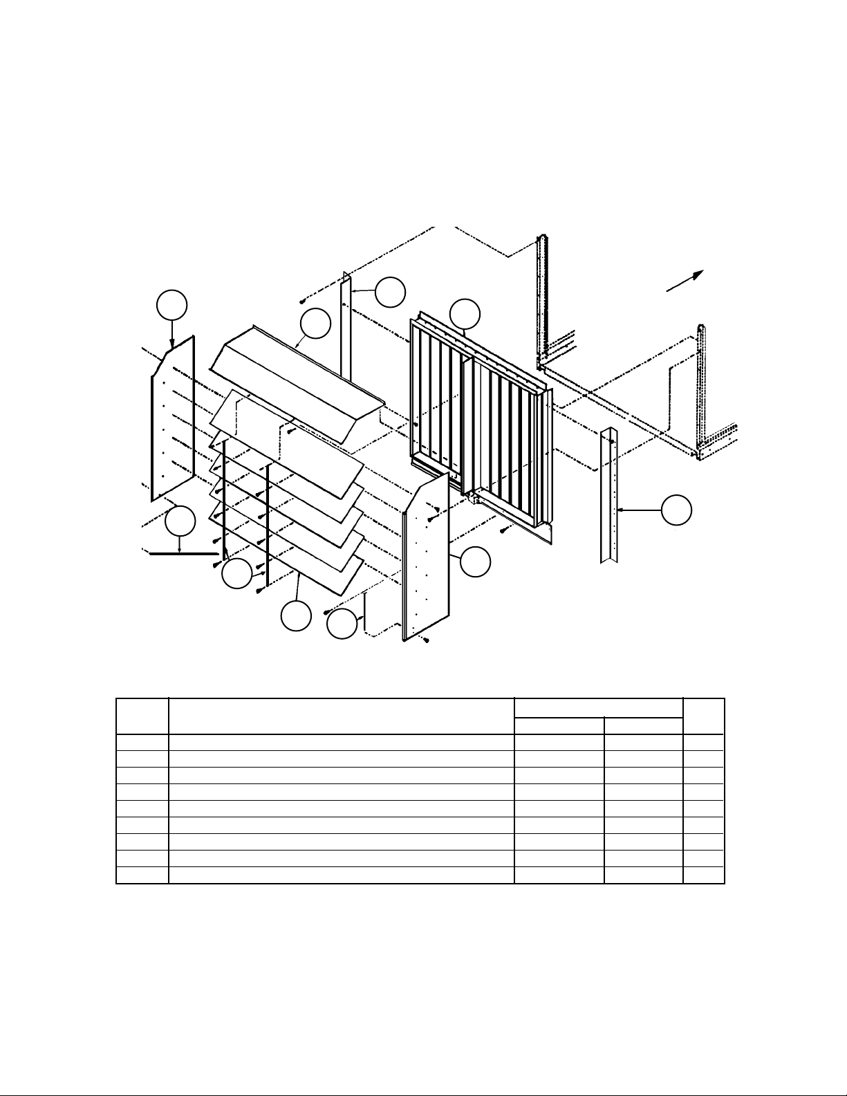
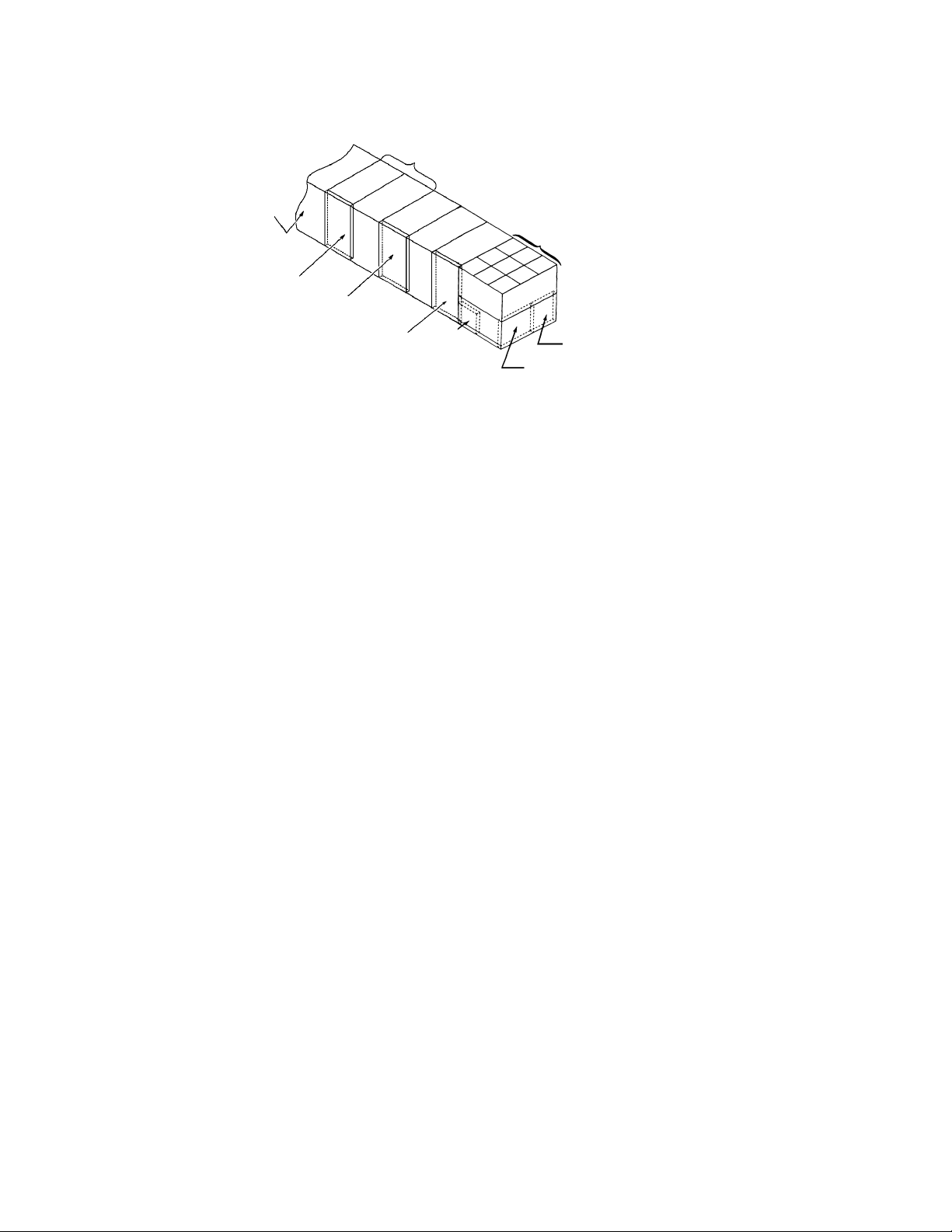
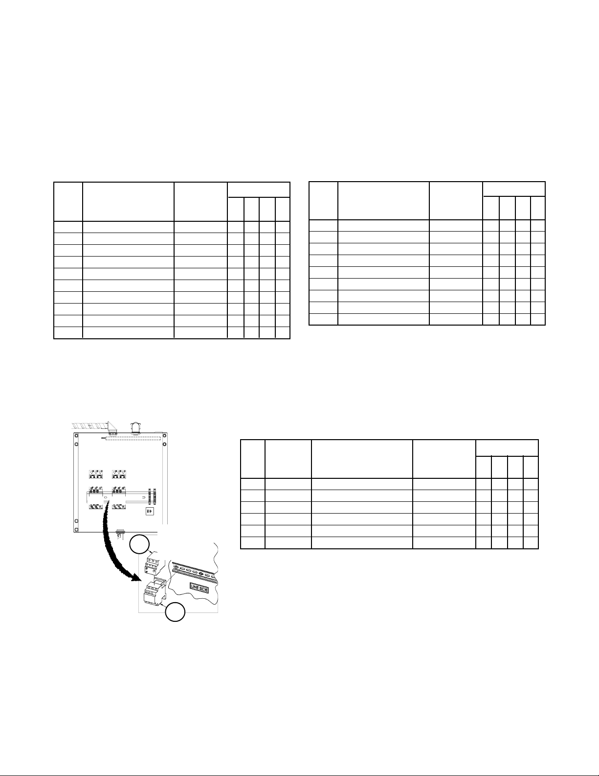
Section A1- Outdoor/Return Air Section
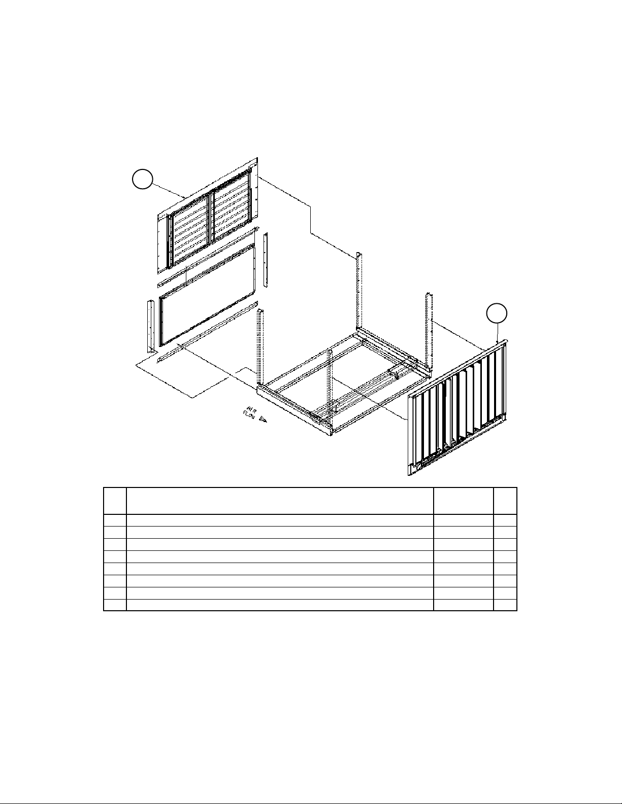
100% Outside Air Damper with Hood
C20= AE or AY and C19= YY
No Return Air Plenum
Air
Flow
11
15
14
13
12
9
4
Section B
9
10
15
Ref. Part Actuator Qty.
No. Description C20= AE C20= AY
4 Damper Assy 1 055979503 055979502 1
Damper Only 098313701 039813701 1
9 Liner 056132601 056132601 2
10 Panel- Hood Side 056131903 056131903 1
11 Panel- Hood Side 056131904 056131904 1
12 Panel- Hood Top 056131802 056131802 1
13 Louver 056132002 056132002 3
14 Channel- Support 056132303 056132303 2
15 Channel- Support 056132102 056132102 2
1
Complete assy includes the damper assy and linkage (no actuator) or actuator assy. For Damper components see the
following page.
Note: The outdoor air damper with actuator (C20= AE) must have MicroTech controls. Dampers without actuators (C20= AY)
must have controls by others (12= YM, YC).
RoofPak Singlezone; RPS,RDT,RFS,RCS 045-079 “D” Rev. U 07/12 RPL 700013700 / Page 19
Page 20
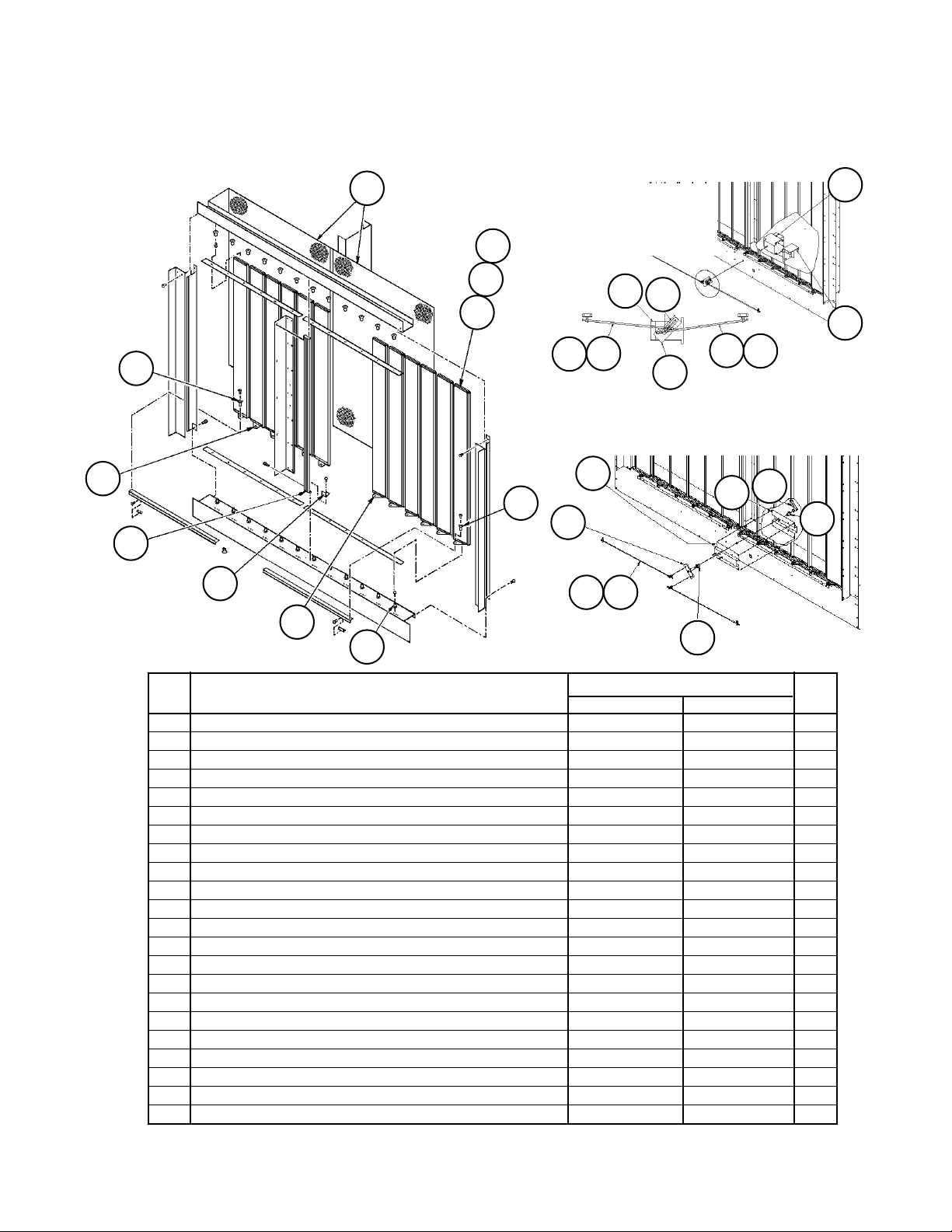
Section A1- Outdoor/Return Air Section
100% Outside Air Damper Detail w/ACT3
C20= AE or AY and C19= YY
23
29
26
16
Damper Assy Detail
28
14
24
13
25
27
Motorized Linkage
Detail:
C20= AE
22
21
4
Manual Linkage Detail:
17
23
5
7
21
20
6
C20= AY
40
21
10
22
17
4
20
40
Ref. Part Actuator Qty.
No. Description C20= AE C20= AY
4 Shaft- Linkage 055979701 not used 2
5 Shaft Assy not used 056081001 1
6 Adapter Plate- Crank Arm 055542001 not used 1
7 Shaft- Linkage not used 055536609 2
10 Channel- Support not used 056080601 1
13 Blade- Damper 044195102 044195102 12
14 Grille 055616801 055616801 2
16 Stop/Anti- Rotate- Damper 065779801 065779801 2
17 Support- Damper Motor 055982001 not used 1
Support- Damper not used 056080701 1
20 Crank Arm- Damper 032279200 not used 1
Crank Arm- Adjustable not used 025072600 1
21 Ball Joint- Damper 000887000 000887000 4
22 Actuator- Motorized ACT3 059999804 not used 1
23 Bushing- Linkage Bar, Nylon 046098300 046098300 12
24 Bushing- Damper Blade, Nylon 043730400 043730400 24
25 Gasket- Vinyl 044193115 044193115 12
26 Gasket- Vinyl 045655715 045655715 1
27 Plug- Damper End 041003501 041003501 12
28 Plug- Damper End 041003502 041003502 6
29 Plug- Damper End 041003503 041003503 6
40 Bearing- Sleeve not used 047138504 2
RoofPak Singlezone; RPS,RDT,RFS,RCS 045-079 “D” Rev. U 07/12 RPL 700013700 / Page 20
Page 21
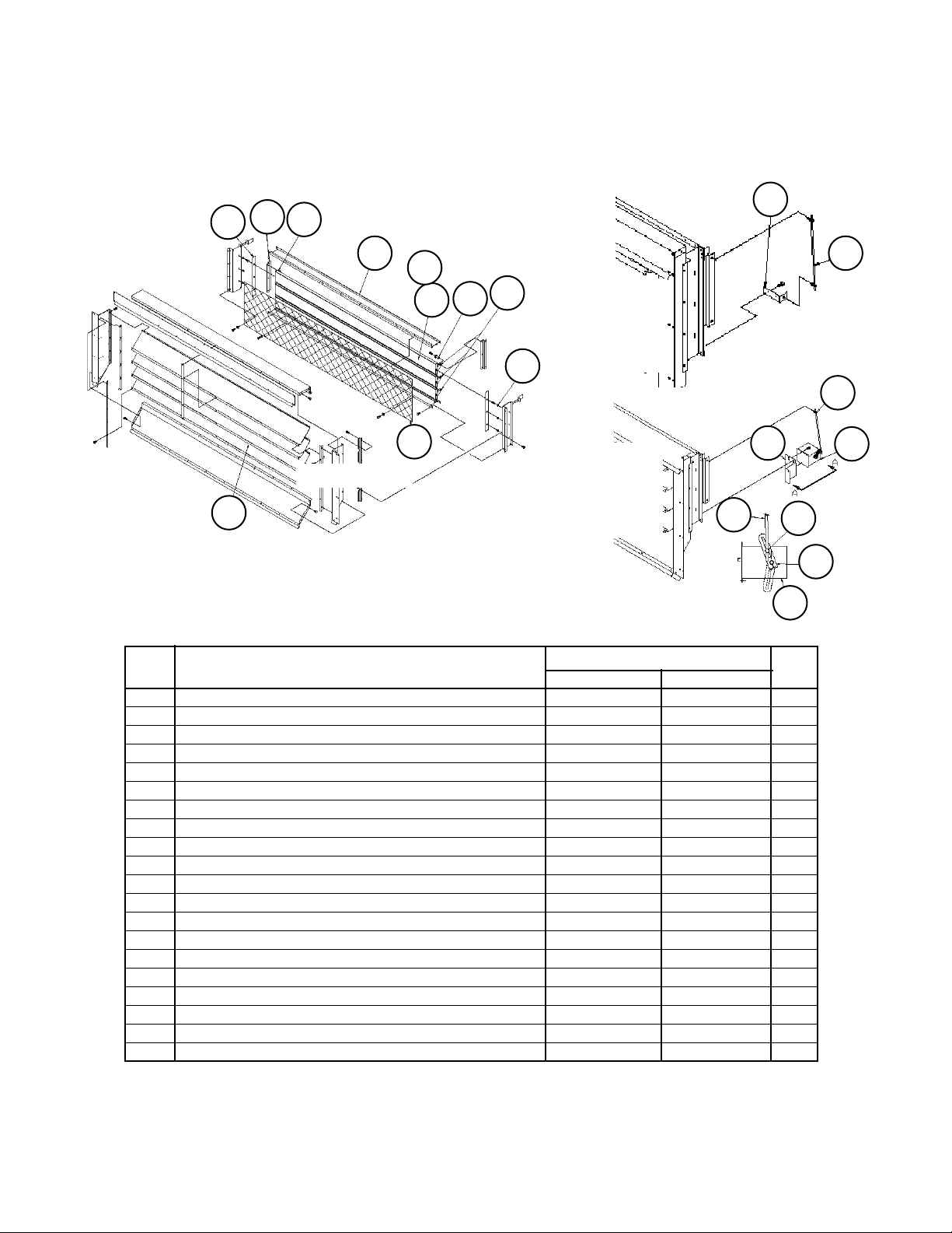
Section A1- Outdoor/Return Air Section
0 - 30% Outside Air Section w/ ACT3
C20= BE or BY
14
11
30
13
9
10
26
Damper Detail
12
31
33
8
32
Linkage
Detail:
Without
Actuator
C20= BY
Linkage
Detail:
With
Actuator
C20= BE
15
View A-A
13
34
35
Ref. Part Actuator Qty.
No. Description C20= BE C20= BY
Damper Assembly- Complete 1 055600803 055600802 1
Damper Assembly
2
098313901 098313901 1
8 Blade- Damper 044193212 044193212 3
9 Gasket- Vinyl 055940203 055940203 1
10 Gasket- Vinyl 044193124 044193124 3
11 Seal- End 055941901 055941901 2
12 Grille 055593601 055593601 1
13 Support- Motor 055595701 not used 1
Rod- Support Angle not used 055608601 1
14 Bar- Linkage 055593701 055593701 2
15 Shaft- Linkage 055536608 055536608 1
26 Louver 055593202 055593202 4
30 Plug- End 041003505 041003505 3
31 Plug- End 041003506 041003506 3
32 Bushing- Damper Blade 043730400 043730400 6
33 Bushing- Linkage Bar, Nylon 046098300 046098300 6
34 Ball Joint- Damper 000887000 not used 2
35 Actuator- Motorized, 120V ACT3 059999804 not used 1
36 Crank Arm- Damper 032279200 not used 1
N/S Isolation Damper C19= BE only 3 055942904 055942904 1
N/S= Not Shown on Diagram.
1
Complete assy includes the damper assy and linkage (no actuator) or actuator assy.
2
Damper only, no linkage or actuator components.
3
Details follow exhaust damper section.
15
34
35
36
RoofPak Singlezone; RPS,RDT,RFS,RCS 045-079 “D” Rev. U 07/12 RPL 700013700 / Page 21
Page 22
Section A1- Outdoor/Return Air Section
0- 100% Economizer Section with Barometric Exhaust Damper
Units without Return Air Fans
C20= DE, DY, EE, EY, FE, FY, GE, or GY, C21= YYYY
12
Back Return (C19= HY) shown.
11
Ref Part Part Qty.
No. Description Number
11 Economizer Damper 1
w/Act.(C20= DE, EE, FE, GE) 055552903 1
w/o Act. (C20= DY, EY, FY, GY) 055552902 1
12 Exhaust Damper Assy
Powered (C20= EE, EY, GE, GY) 112040447 1
Barometric (C20= DE, DY, FE, FY) 112039647 1
N/S Isolation Damper C19= BE only 2 055942904 1
N/S= Not Shown on diagram.
1
Economizer with actuator (C20= DE, FE, GE, HE) requires MicroTech Controls. Without actuator (C20= DY, FY,
GY, HY), requires controls by others (C12= YM, YC). Economizer detail two pages after next.
2
Details follow exhaust damper section.
RoofPak Singlezone; RPS,RDT,RFS,RCS 045-079 “D” Rev. U 07/12 RPL 700013700 / Page 22
Page 23

Section A1- Outdoor/Return Air Section
0- 100% Economizer Section with Barometric Exhaust Damper
Units with 40” Return Air Fans
C20= DE, DY, EE, EY, FE, FY, GE, or GY
C21= 40B1, 40B2, 40B3, 40W1, 40W2, 40W3
12
Bottom Return (C19= BY, BE, BD, BE) shown.
(see Return Fan Detail)
55 56
(see Return Fan Detail)
Ref Part Part Qty.
No. Description Number
11 Economizer Damper 1
w/Actuator C20= DE, EE, FE, GE 055552903 1
w/o Actuator C20= DY, EY, FY, GY 055552902 1
12 Exhaust Damper Assy
Powered C20= EE, EY, GE, GY 055552820 1
Barometric C20= DE, DY, FE, FY 055552810 1
N/S Isolation Damper C19= BE only 2 055942904 1
55 56
50
51
11
50 Belt Guard C49= D or F 055962201 1
51 Belt Guard C49= D or F 055962202 1
55 Gasket 055921413 2
56 Gasket 055921414 2
N/S= Not Shown on diagram.
1
Economizer with actuator (C20= DE, FE, GE, HE) requires MicroTech Controls. Without actuator (C20= DY, FY, GY,
HY), requires controls by others (C12= YM, YC). Economizer detail on page after next.
2
Details follow exhaust damper section.
RoofPak Singlezone; RPS,RDT,RFS,RCS 045-079 “D” Rev. U 07/12 RPL 700013700 / Page 23
Page 24
Section A1- Outdoor/Return Air Section
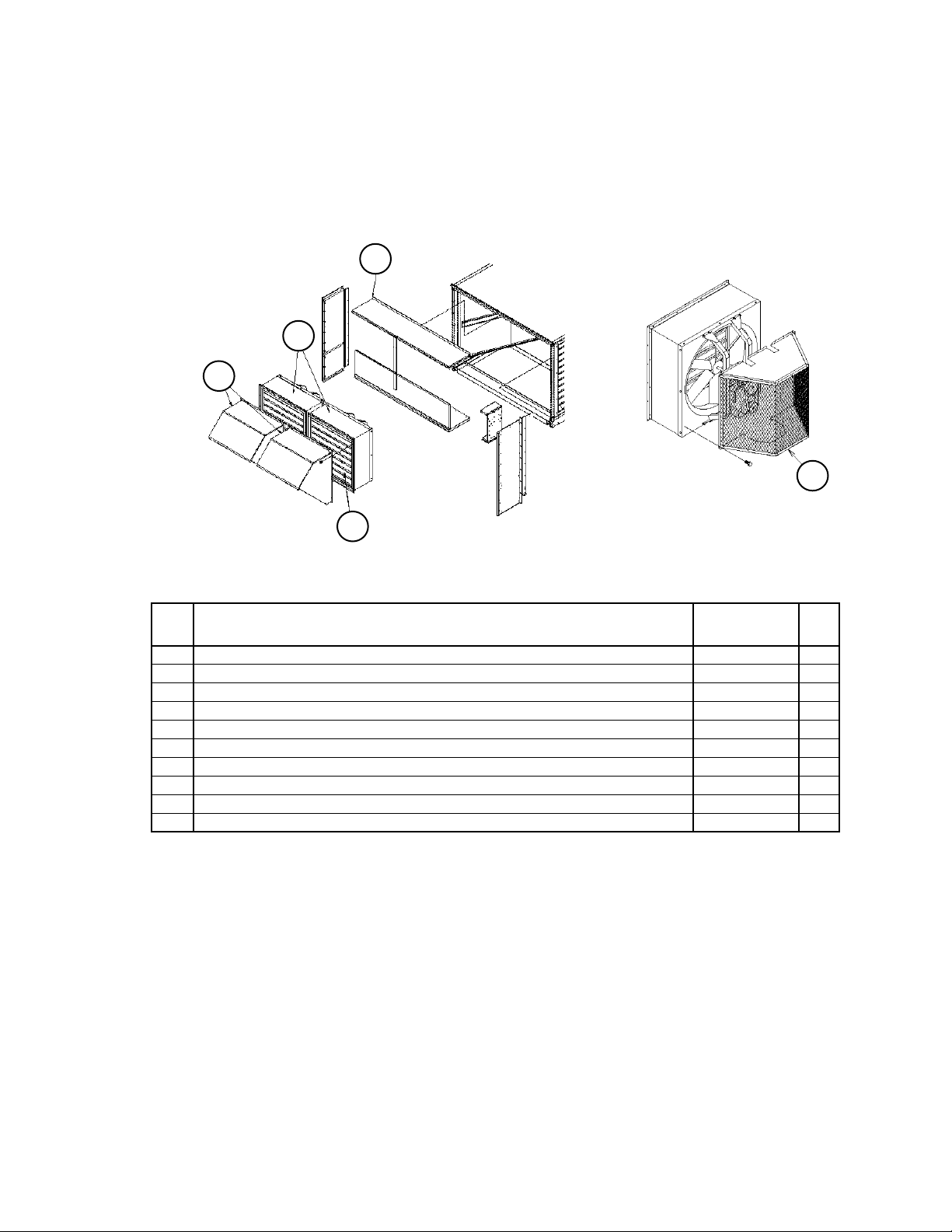
0- 100% Economizer Section with Prop Exhaust Fan & Damper
C20= HE, HY, JE or JY, C24= 1 or 2
Diagrams
Section Assembly Detail
20
Fan Guard
-2 fan arrangement shown(C24= 2)
6
41
6
Ref. Part Part Qty.
No. Description Number
N/S Isolation Damper w/ actuator C19= BE only 1 055942904 1
N/S Economizer Damper
3
w/Act.(C20= HE, JE) 055552903 1
w/o Act. (C20= HY, JY) 055552902 1
6 Fan Assembly 4 208/230/460V 111056601
Fan Assembly 4 575V 111056602
15 Fan Guard 111181901 1
20 Panel- Weather Hood 111173101 1
41 Hood- Prop Exhaust 111182301 1
Grille Only- Prop Exhaust Hood 111182101 1
N/S= Not Shown on diagram.
1
See detail following Exhaust Damper Detail.
3
Economizer with actuator (C20= DE, FE, GE, HE) requires MicroTech Controls. Without actuator (C20= DY, FY, GY, HY),
requires controls by others (C12= YM, YC). Economizer detail two pages after next.
4
See detail following Isolation Damper Detail.
5
Quantity may be one (Code 24= 1) or two (Code 24= 2).
6
Quantity is PER fan.
15
5
5
6
6
6
6
RoofPak Singlezone; RPS,RDT,RFS,RCS 045-079 “D” Rev. U 07/12 RPL 700013700 / Page 24
Page 25

Section A1- Outdoor/Return Air Section
0 - 100% Economizer Damper Detail
C20= DE, DY, EE, EY, FE, FY, GE, GY, HE, HY, JE, JY
Diagrams
24
26
23
Damper Detail
28
18
19
16
24
29
13
27
25
Linkage
Detail:
With
Actuator
C20= *E
7
21
20
21
RoofPak Singlezone; RPS,RDT,RFS,RCS 045-079 “D” Rev. U 07/12 RPL 700013700 / Page 25
6
22
Detail
19
17
21
4
* D, E, F, G, H, J
21
7
21
Linkage
Detail:
Without
Actuator
C20= *Y
17
5
6
11
20
Page 26
Section A1- Outdoor/Return Air Section
0 - 100% Economizer Damper w/ ACT3
C20= DE, DY, EE, EY, FE, FY, GE, GY, HE, HY, JE, JY
Components
Ref. Part Actuator Qty.
No. Description C20= *E C20= *Y
Damper Assy- Complete 1 055552903 055552902 1
Damper Assembly 2 098313201 098313201 1
4 Shaft Assembly 058390001 not used 1
5 Shaft Assembly not used 056081001 1
6 Plate- Crank Arm 055542001 1
Shaft Assembly 058390001 1
7 Shaft- Linkage 058389901 058389901 1
11 Channel- Support not used 111087501 1
13 Blade- Damper 044195102 044195102 12
16 Stop/Anti-Rotate- Damper 065779801 065779801 4
17 Support- Damper Motor 055546601 1
Channel- Support 111087502 1
18 Bar- Linkage 044194800 044194800 2
19 Drive Tab- Linkage Bar 044194900 044194900 2
20 Crank Arm- Damper 032279200 1
Crank Arm- Adjustable 025072600 1
21 Ball Joint- Damper 000887000 000887000 4
22 Actuator- ACT3 059999804 not used 1
23 Bushing- Linkage Bar 046098300 046098300 12
24 Bushing- Damper Blade 043730400 043730400 24
25 Gasket- Vinyl 044193115 044193115 12
26 Gasket- Vinyl 045655715 045655715 2
27 End Plug- Damper 041003501 041003501 12
28 End Plug- Damper 041003502 041003502 6
29 End Plug- Damper 041003503 041003503 6
N/S Gasket- Neoprene 3 056003501 056003501 4
N/S= Not Shown on Diagram.
1
Complete assy includes the damper assy and linkage (no actuator) or actuator assy.
2
Damper only, no linkage or actuator components.
3
Applied from outer edge of assembly to inside edge of center support and flush with edge of the bottom channel.
RoofPak Singlezone; RPS,RDT,RFS,RCS 045-079 “D” Rev. U 07/12 RPL 700013700 / Page 26
Page 27
Section A1- Outdoor/Return Air Section
Return Air Plenum Isolation Damper w/ Actuator ACT6
C19= BE
Damper Detail
16
15
424
23
20
19
17
21
18
22
15
ACT6 Motorized Actuator
3
22
20
22
View A-A
Detail
Ref. Part Part Qty.
No. Description Number
Isolation Damper Assy- Motorized 055921124 1
3 Motor Mount Assembly 055921201 1
4 Blade Assembly- Return 4” 055921302 1
15 Angle- Linkage 055917702 1
16 Angle- Blade 055638102 1
17 Shaft- Damper Blade 055637801 18
18 Shaft- Linkage 055536601 1
19 Bearing- Flange, Nylon 001113500 18
20 Actuator- Motorized- SPDT ACT6 059999804 1
21 Crank Arm- Damper 032279200 1
22 Ball Joint 000887000 2
23 Bearing- Sleeve 047138507 27
24 Gasket- Vinyl 030051985 10
RoofPak Singlezone; RPS,RDT,RFS,RCS 045-079 “D” Rev. U 07/12 RPL 700013700 / Page 27
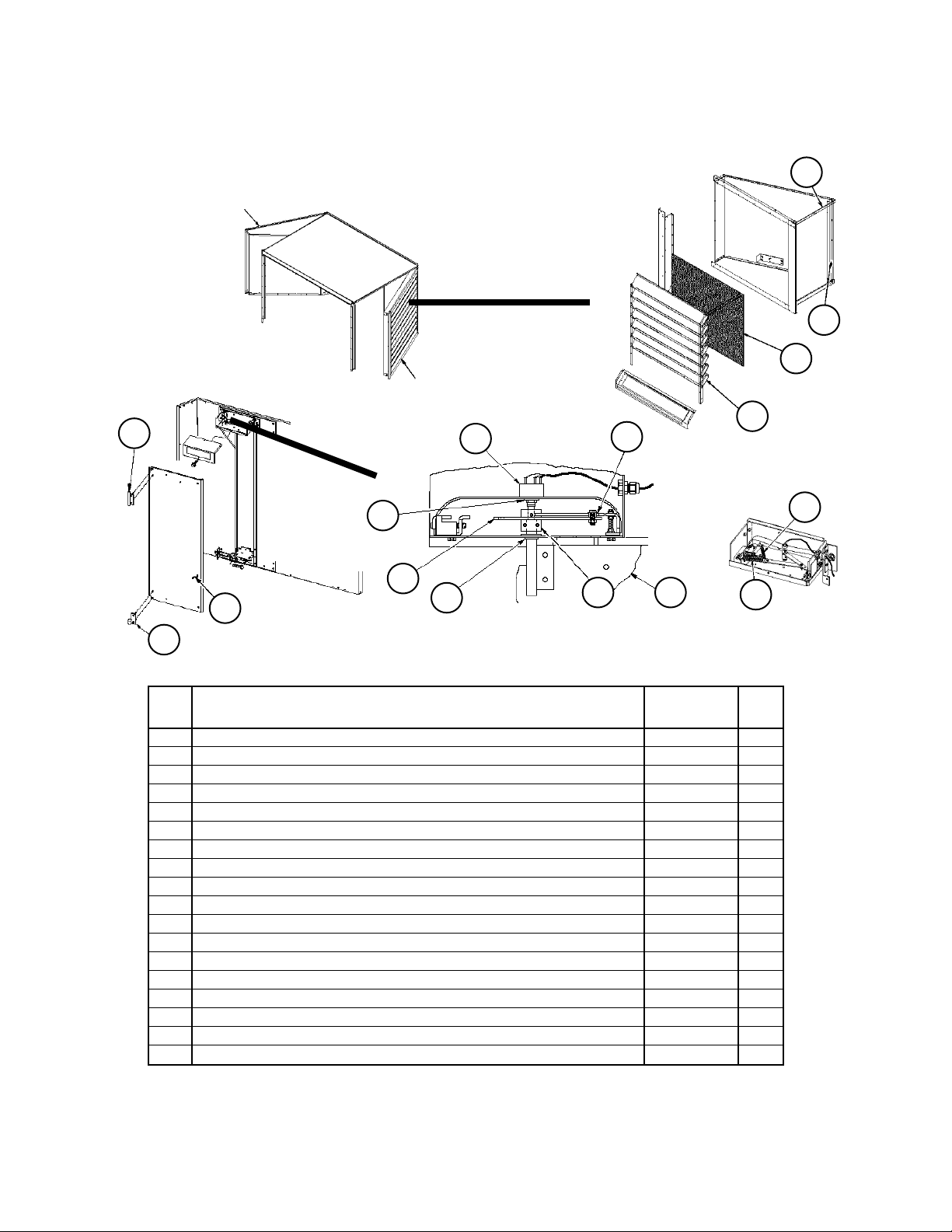
Page 28

Section A1- Outdoor/Return Air Section
Prop Exhaust Fan & Damper Detail
C20= HE, HY, JE or JY, C24= 1 or 2
6
Fan Assembly Components
- 2 Fan Arrangement Shown-
6C
6B
Code 24= 2
6E
1B
6H
6I
460V
6G
575V
1A
54
Lube Line Detail
6A
51
53
1
Control Box
(see following page
Voltage
Ref. Sch. Part Part
208V
No. Sym. Description Number
230V
1 AFD20 Inverter see charts on following page
1A Resistor- Inverter 044690105 1 1 1 1
1B Jumper- Inverter
1
055719731 3 3 3 3
6 Fan Assembly- Complete 111056601
Fan Assembly- Complete 111056602
6A Damper- Backdraft
6B Fan Prop- 36” 300044027 14 14 14 1
6C Fan Shaft 300044028 14 14 14 1
6D Bearing 300044029 24 24 24 2
6E Fan Sheave 019291400 14 14 14 1
6F Bushing- Fan Sheave 000804000 14 14 14 1
6G Belt 049260805 24 24 24 2
6H Motor Sheave 000607600 14 14 14 1
6I Motor 300046887 14 14 1
Motor 300046251 1
3
4
4
4
4
4
4
4
4
4
51 Tube- Plastic 2 020954800 8’ 8’ 8’ 8’
53 Coupling- Tube
54 Fitting- Grease
1
Quantity= 2 when Inverter model 3500 (Code 15= G) is used.
2
Quantity shown are for 1 fan. Quantities for 2 fan units: Ref. 51= 25’; Ref. 53= 4; Ref. 54= 4.
3
Contact Daikin McQuay Parts.
4
Quantity is PER fan.
2
.25 x .125 FPT 021213800 2 2 2 2
2
000109800 2 2 2 2
6D
6F
RoofPak Singlezone; RPS,RDT,RFS,RCS 045-079 “D” Rev. U 07/12 RPL 700013700 / Page 28
Page 29
Section A1- Outdoor/Return Air Section
Prop Exhaust Fan & Damper Detail
C20= HE, HY, JE or JY, C24= 1 or 2
Continued
Inverter- 1 Fan Units (Code 24= 1)
Voltage
Code Inverter Model Part
208V
230V
15= Number
460V
A 550 112046015 1 1
550 112046002 1
G 3500 098656916 1
3500 098656926 1
3500 098656903 1
3500 098656943 1
R VTAC9 111046868 1 1
VTAC9 111046854 1
S MD2 349956609 1 1
MD2 349956625 1
Prop Exhaust Fan Control Box
Voltage
Ref. Sch. Part Part
No. Sym. Description Number
OL51 OL52
M51 M52
2 Fan Units
220
Contactors &
Overloads
Detail
220 OL511, 52 Overload 349934663 2
Overload 349934662 2
Overload 349934660 2
Overload 349934659 2
230 M511,52 Contactor 349932123 2 2
Contactor 349932121 2 2
NOTE: All quantities are PER fan.
1
OL51 & M51 are also used on units with 1 prop exhaust fan where the Inverter is
field installed.
Inverter- 2 Fan Units (Code 24= 2)
Voltage
Code Inverter Model Part
15= Number
575V
A 550 112046017 1 1
550 112046004 1
G 3500 098656918 1
3500 098656928 1
3500 098656905 1
R VTAC9 111046870 1 1
VTAC9 111046856 1
S MD2 349956611 1 1
MD2 349956627 1
208V
208V
230V
230V
460V
460V
575V
575V
230
RoofPak Singlezone; RPS,RDT,RFS,RCS 045-079 “D” Rev. U 07/12 RPL 700013700 / Page 29
Page 30
Section A1- Outdoor/Return Air Section
LH Louvered Door Assy
Section Final
Assembly
105
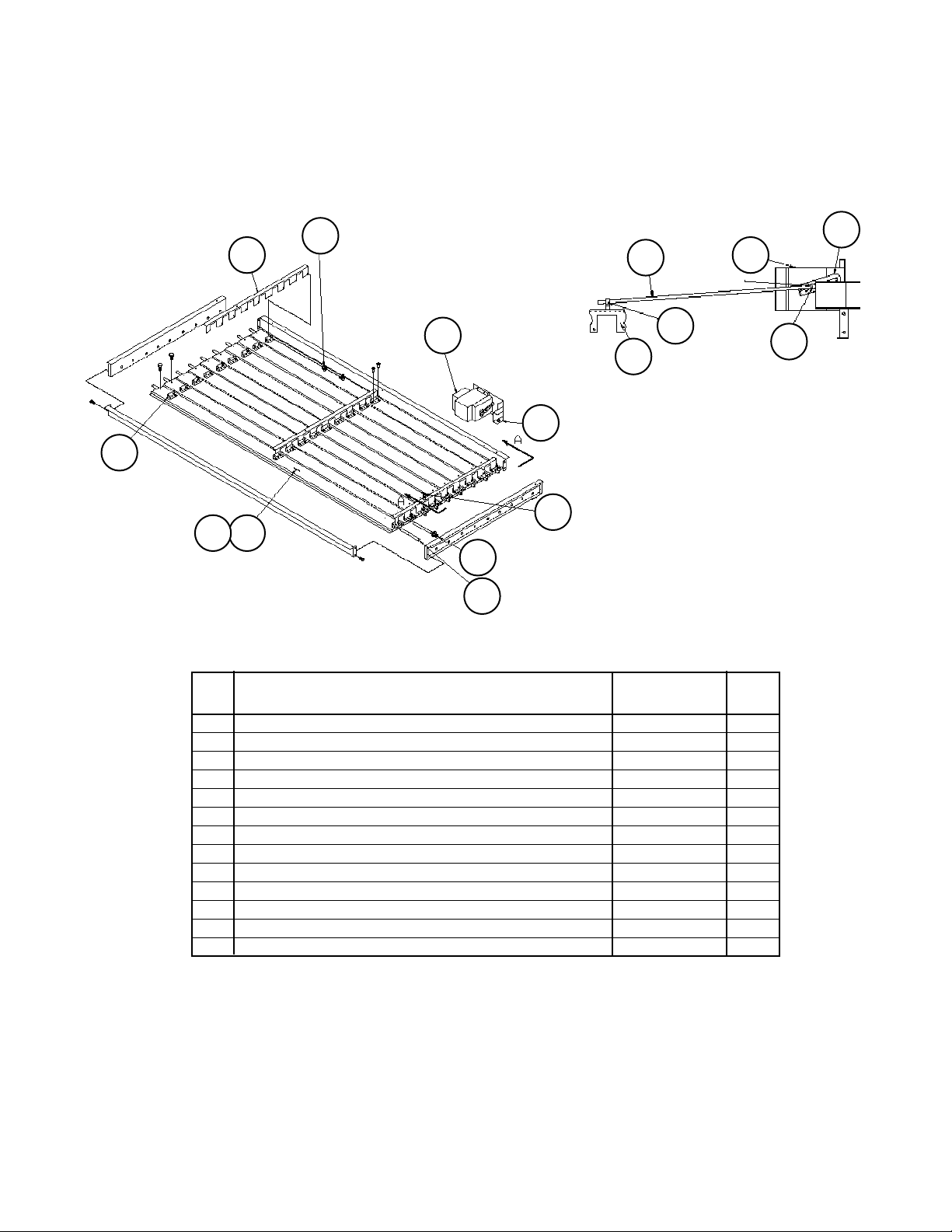
Design Flow Detail
Code 20= FE, FY, GE, GY
Louvered Door
Assembly Detail
RH Louvered Door Assy
9
➤
4
➤
3
2
1
127
12
110
104
106
Design Flow Vane and
Vane Bearings Detail
Ref Part Part Qty.
No. Description Number
1 Louver Panel Left Hand Door 059595204 10
Louver Panel Right Hand Door 059595203 10
2 Grille 055541401 1
3 Gasket 055921402 2
4 Gasket 055921401 1
9 Potentiometer 098663701 1
12 O’Ring- Potentiometer 098663801 1
104 Panel- Vane 098661802 1
105 Shaft- Upper 098662601 1
106 Bearing- Lower 091634501 1
109 Crank Arm Assy Left Hand Door 091658802 1
Crank Arm Assy Right Hand Door 091658801 1
110 Link Arm
120 Bearing 060014201 1
127 Bearing 047138535 1
130 Spring- Main .75” x 2” 098664801 1
131 Spring- Secondary .30” x 1.5” 098664901 1
N/S Leveling Kit- Design Flow 091659301 1
1
Quantity is PER door.
2
P/N is unit specific. Contact Daikin McQuay Parts with overall length and bolt hole spacing so that the correct part
can be identified.
120
Adjuster Control Assy
Detail
109 104
130
2
1
Spring
131
Detail
1
RoofPak Singlezone; RPS,RDT,RFS,RCS 045-079 “D” Rev. U 07/12 RPL 700013700 / Page 30
Page 31
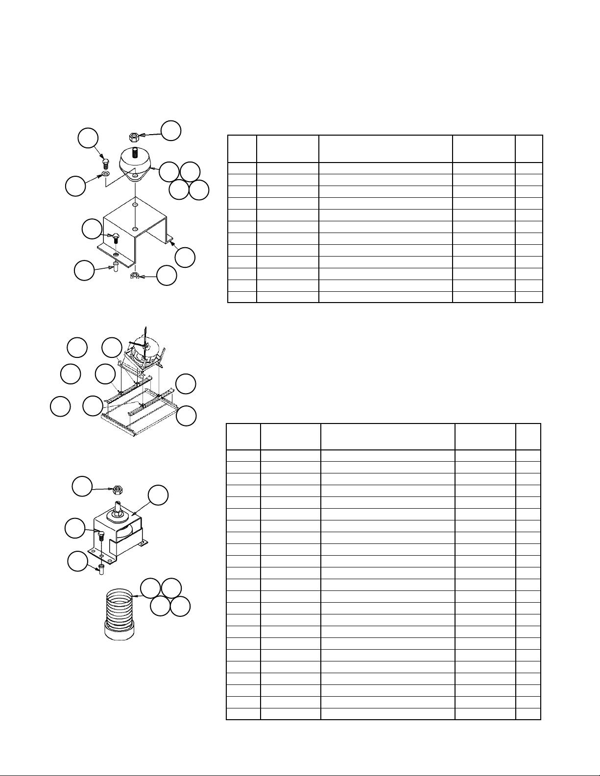
Section A1- Outdoor/Return Air Section
Return Air Fan Detail- Fan Mounts
164
93
161
163
189
181
92
89
81
Rubber Mounts
or
61
or
63
or
64
188
Spring Mounts
91
61 62
91
121
161 162
163
Rubber Mounts (Code 15= 40B1 or 40W1)
Ref. Fan Motor Part Part Qty.
No. HP Description Number
21 All Channel- Mount Support 055512101 4
63
64
21
61 2 - 20 Rubber Mount- Black 021639704 1
25, 30 Rubber Mount- Red 021639701 1
62 2 - 10 Rubber Mount- Black 021639704 1
15 - 30 Rubber Mount- Red 021639701 1
63 2 - 30 Rubber Mount- Black 021639704 1
64 2 - 30 Rubber Mount- Black 021639704 1
81 All Nut 059992201 8
89 All Screw 112047201 8
91 All Nut- 1/2-13 032333305 12
92 All Screw- Cap, 1/2-13 X 1” 040499501 8
93 All Washer- Plain, 1/2” 040500310 8
Mounting Diagram
162
or
62
164
Spring Mounts (Code 15= 40*2) & Seismic Spring (40*3)
Ref. Fan Motor Part Part Qty.
No. HP Description Number
121 All Mount
Spring (C15= 40*2) 251783201 4
Seismic (C15= 40*3) 251783301 4
161 2 Spring Mount- Yellow 251784501 1
3, 5 Spring Mount- Black 251784601 1
7.5- 15 Spring Mount- Purple 251784701 1
20- 30 Spring Mount- Brown 251784801 1
162 2, 15, 20, 25 Spring Mount- Brown 251784801 1
3- 10 Spring Mount- Purple 251784701 1
30 Spring Mount- Red 251784901 1
163 2- 5 Spring Mount- Yellow 251784501 1
7.5- 30 Spring Mount- Blue 251784401 1
164 2 Spring Mount- Brown 251784801 1
3- 7.5 Spring Mount- Black 251784601 1
10- 20 Spring Mount- Yellow 251784501 1
25, 30 Spring Mount- Blue 251784401 1
181 All Nut
Spring (C15= 40*2) 059992201 12
Seismic (C15= 40*3) 111056301 20
188 All Nut 040500002 4
189 All Screw
Spring (C15= 40*2) 112047201 12
Seismic (C15= 40*3) 112047201 20
RoofPak Singlezone; RPS,RDT,RFS,RCS 045-079 “D” Rev. U 07/12 RPL 700013700 / Page 31
Page 32

Section A1- Outdoor/Return Air Section
Return Air Fan Detail (Code 21-= 40B* or 40W*)
17
6
15
Actuator
Lever
2
27
2613
Open Closed
1620
1
7
2
14
10
12
16A
19A
15A
20
Ref. Motor Part No VIV w/ VIV
No. HP Description C20= 40B* C20=40W* Qty.
1 Motor see table on following page
2 All Variable Inlet Vanes Assembly 032739700 1
Drive Collar Only 032590100 1
Crank Rod Only 032590700 7
Vane- CW 032737902 7
Dust Shield 031818400 1
All Fan Housing Assy- Inlet Funnel 031940905 1
6 All Wheel- Air Foil Fan, SI/SW 40° 066543242 066543242 1
7 All Mount- Motor 055552401 055552401 1
10 All Support- Motor 055539301 1
12 All Crank Arm 055541801 1
13 All Shaft 1.937” Diameter 055541902 055541902 1
14 2 - 20 Actuator- Motorized ACT2 059999801 1
25, 30 Actuator- Motorized ACT2 059999802 1
15 All Coupling- 1/8” MPT 027674000 027674000 2
15A All Crank Arm- Damper 032279200 1
16 All Coupling- Reducer 1/4” X 1/8” FPT 021213800 021213800 2
16A All Ball Joint- Damper 000887000 2
17 All Tubing- Plastic 021136745 021136745 2
19 All Grease Fitting 1/8” MPS 000109800 000109800 2
19A All Shaft- Linkage 055536610 2
20 All Bearing- Ball 1.937” bore 020648603 020648603 2
26 All Key- Wheel 1/2” X 5 1/2” 023221513 023221513 1
27 All Key- Fan Sheave 1/2” X 4 1/2” 023221507 023221507 1
* Mounting type 1= RIS, 2= Spring, 3= Spring w/ seismic snubbers.
1719
16
15
RoofPak Singlezone; RPS,RDT,RFS,RCS 045-079 “D” Rev. U 07/12 RPL 700013700 / Page 32
Page 33

Section A1- Outdoor/Return Air Section
Return Air Fan Motors
H.P. Unit ODP HiEff ODP PrEff. TEFC HiEff TEFC PrEff
Voltage C22= *EY C22= *JY C22= *HY C22= *KY
C09= 12
2 208/60/3 039895700 046515500 049100300 N/A
3 208/60/3 039447500 065817100 047358100 065819400
5 208/60/3 039447600 065817200 049186800 065819500
7.5 208/60/3 037530300 065817300 047665900 065819600
10 208/60/3 038999000 065817400 047666100 065819700
15 208/60/3 039896200 065817500 049186900 065819800
20 208/60/3 039895800 065817600 049187000 065819900
25 208/60/3 039448900 065817700 049187100 065820000
30 208/60/3 041775200 205066500 049187200 205066800
C09= 29
2 230/60/3 039446300 205163500 047446000 073321000
3 230/60/3 039442400 065818100 049262300 065820100
5 230/60/3 039442500 065818200 040161200 065820200
7.5 230/60/3 039448700 065818300 049100500 065820300
10 230/60/3 039446500 065818400 044691100 065820400
15 230/60/3 039446600 065818500 038689700 065820500
20 230/60/3 039448800 065818600 040161300 065820600
25 230/60/3 039896100 065818700 040161400 065820700
30 230/60/3 040626800 205066600 049025300 205066900
C09= 27
2 460/60/3 039446300 205163500 047446000 073321000
3 460/60/3 039442400 065818100 049262300 065820100
5 460/60/3 039442500 065818200 040161200 065820200
7.5 460/60/3 039448700 065818300 049100500 065820300
10 460/60/3 039446500 065818400 044691100 065820400
15 460/60/3 039446600 065818500 038689700 065820500
20 460/60/3 039448800 065818600 040161300 065820600
25 460/60/3 039896100 065818700 040161400 065820700
30 460/60/3 040626800 205066600 049025300 205066900
C09= 37
2 575/60/3 049181000 205168300 049188200 046514400
3 575/60/3 046741600 046511700 049188300 046514500
5 575/60/3 046741900 205168900 049188400 046514600
7.5 575/60/3 047443300 205168800 049188500 046514700
10 575/60/3 047443400 205168600 049188600 065821400
15 575/60/3 047443500 205166600 049185200 065821500
20 575/60/3 049181100 205166800 049188700 065821600
25 575/60/3 049181200 205166900 049188800 065821700
30 575/60/3 049181300 205066700 049188900 205067000
RoofPak Singlezone; RPS,RDT,RFS,RCS 045-079 “D” Rev. U 07/12 RPL 700013700 / Page 33
Page 34
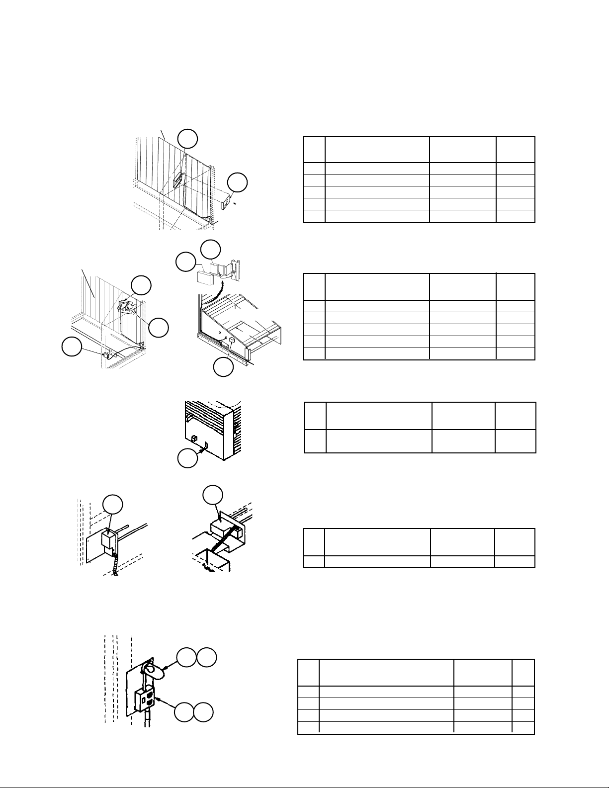
Section A1- Outdoor/Return Air Section
Section Mounted Controls
OAE, RAE, LT11, S11, REC11
Bottom Return
Shown
C19= BY or BE
Economizer
43
Economizer
40
41
40
41
OAE- Mechanical Enthalpy (Code 17= Y*)
Ref Part Part
No. Description Number Qty.
40 Mount- OAE Enthalpy 055800101 1
41
41 Enthalpy Assembly
(knob & Control) 055740691 1
Knob only 026215500 1
Control OAE only 030706702 1
40
OAE & RAE Differential Enthalpy (Code 17= C*)
Ref Part Part
No. Description Number Qty.
Mixing Box
40 Mount- OAE Enthalpy
Economizer Units 059328901 1
Mixing Box Units 055800301
41 Control- OAE 049262201 1
43 Control- RAE 049262202 1
43
RAT- Outdoor Air Temperature Sensor
Ref Part Part
No. Description Number Qty.
7 Return Air Temp.
Sensor- RAT 193414602 1
7
30
SD2- Return Air Smoke Detector
C16= 1 or 3
30
Ref Part Part
Back Return
C19= HY
Return Air Opening
Return Air
Opening
Bottom Return
C19= BY or BE
No. Description Number Qty.
30 Smoke Detector SD2 098873101 1
LT11- Return Fan Light/S11- Return Fan Light
Switch/ REC11- Return Fan Light Receptacle
84 85
88 89
RoofPak Singlezone; RPS,RDT,RFS,RCS 045-079 “D” Rev. U 07/12 RPL 700013700 / Page 34
C49= E or F
Ref Part Part
No. Description Number Qty.
84 Light Fixture 042229500 1
85 Bulb- LT11 065492402 1
88 Light Switch- S11 065492201 1
89 Receptacle- REC11 030187000 1
Page 35

Section A1- Outdoor/Return Air Section
Ebtron Sensor Detail
Code 20= KE, KY, LE, LY, ME, MY
Ref. Part Part
No. Description Number Qty.
394 Ebtron Sensor 111055303 1 1
1
This is the standard Ebtron ‘Silver’ sensor. Some unit specials will use an
Ebtron “gold” sensor p/n 111055307.
394
RoofPak Singlezone; RPS,RDT,RFS,RCS 045-079 “D” Rev. U 07/12 RPL 700013700 / Page 35
Page 36

Section A2- Outdoor/Return/Heat Recovery Air Section
➩
Primary Codes that pertain: 19, 20, 21, 22, 23, 24
Additional Codes that pertain: 06, 09, 14, 15, 16, 17, 49
Codes 19 and 20 determine the base section. Code 19 is the Return Air Plenum, and is always BY (bottom return
air). Code 20 determines the type of Outdoor Air/Heat Recovery control is used. C20= 3E or 5E the unit has a 6”
Heat Recovery Wheel. C20= 4E or 6E the unit has a 12” Heat Recovery Wheel
Codes 21, 22, 23 determine the return air fan, motor and drives. The fan section parts, the fans, and the motors are
listed in this section. The drive components (fan sheave, motor sheave, belt, and fan bushing) are not listed
as they are unique to the unit. If a drive component is required you may use the number from the part and
cross reference it with the Drive Components Cross Reference form number: 571006, or contact Daikin
McQuay Parts to ensure that the needed part(s) are correctly identified. The motors range anywhere from 2- 30
horsepower, and the fan is a 24” Single width airfoil wheel.
Code 24 determines if the Heat Wheel has a frost protection inverter mounted in the section.
Code 06 determines the panels used in final cabinet assembly.
Notes
Code 09, the voltage, is part of the motor part number identification.
Code 14 determines if the return fan has an inverter, or variable frequency drive (VFD). If code 14 equals 2- 9, then
the unit has a return fan inverter.
Code 15, determines the type of Return Fan inverter (mounted in a separate section or the supply air section).
Code 16 determines the smoke detector which is located in the return air cabinet. C16= 1 or 3 if a smoke detector
(SD2) is present.
Code 17 determines the Enthalpy Control. If C17= Y* and the unit has an economizer there is a mechanical enthalpy
control (OAE). If C17= C*, there is a differential enthalpy control (OAE + RAE).
Code 49 determines if the return air cabinet has a light, switch and receptacle (C49= E).
RoofPak Singlezone; RPS,RDT,RFS,RCS 045-079 “D” Rev. U 07/12 RPL 700013700 / Page 36
Page 37

Section A2- Outdoor/Return/Heat Recovery Air Section
Cabinet Gaskets, Doors, Hardware, Exhaust Hoods
C20= 3E, 4E, 5E or 6E
Cabinet Gaskets, Doors and
Exhaust Hoods
503
502
418
(LH components shown)
418
437
439
440
437
419
437
415
Hood
414
423
505
Exhaust Hood-
504
Ref. Part Part Qty.
No. Description Number
414 Hinge 032457700 2
415 Door 24” 111208802 4
418 Door- Exhaust 48” 111209601 1
419 Door- Exhaust 48” 111209602 1
420 Door 24” 111208801 4
421 Door 48” 111209202 1
423 Door 48” 111209201 1
437 Gasket- Vinyl 055921411 24
439 Gasket- Vinyl 055921409 12
440 Gasket- Vinyl 055921408 24
502 Damper- Back Draft 39.38 x 31.25 111209301 2
503 Panel- Hood 111209802 2
504 Panel- Hood RH 111074702 2
505 Panel- Hood LH 111074602 2
See Detail to Left
420
421
437
414
437
RoofPak Singlezone; RPS,RDT,RFS,RCS 045-079 “D” Rev. U 07/12 RPL 700013700 / Page 37
Page 38

Section A2- Outdoor/Return/Heat Recovery Air Section
Base Components, Hood, Dampers
C20= 3E, 4E, 5E or 6E
Outdoor Air Intake Hood Detail
140
148
See Hood
Detail to Left
Base Assembly
160
230
142
144
230
1
145
146
141
31
30
12
210
215
210
215
Ref. Part Part Qty.
No. Description Number
1 Fan Assembly
12 Damper- OA Low Leak w/ actuator ACT3
12A Damper- RA Low Leak w/ actuator ACT4
1
2
2
1
30 Channel- Fan 251849801 1
31 Channel- Fan 251849901 1
140 Panel- Outdoor Intake Hood, Top 251840701 1
141 Panel- Outdoor Intake Hood, Side 251841101 1
142 Panel- Outdoor Intake Hood, Side 251841201 1
144 Louver- Outdoor Intake Hood 251840801 1
145 Louver- Outdoor Intake Hood 251840901 1
146 Louver- Outdoor Intake Hood 251841001 1
148 Screen- Outdoor Intake Hood 251841801 2
160 Wheel, Enthalpy- Heat Recovery
3
201 Filter Rack- Upper LH 251846701 1
202 Filter Rack- Upper RH 251846702 1
204 Filter Rack- Lower LH 251846602 1
205 Filter Rack- Lower RH 251846601 1
210 Filter- 30% 16 x 20 x 2 031298001 14
211 Filter- 30% 16 x 25 x 2 031298002 42
215 Stop- Filter 011484101 14
230 Damper- Economizer w/ actuator ACT12,13
1
See detail on following page.
2
See detail following Fan Mount detail.
3
See detail following “L” Bypass Damper detail..
4
See detail following Low Leak Damper detail.
4
2
201
202
211
205
211
204
12A
1
RoofPak Singlezone; RPS,RDT,RFS,RCS 045-079 “D” Rev. U 07/12 RPL 700013700 / Page 38
Page 39

Section A2- Outdoor/Return/Heat Recovery Air Section
40” Return Fan Detail
10A
10B
7
Thrust Restraint Detail
10C
1
40
11
10
Ref. Part Part Qty.
No. Description Number
1 Motor
7 Gasket 251851101 1
10 Fan Assembly 209994902 1
10A Fan Wheel 010255226 1
10B Bearing- Inlet Side 020648654 1
N/S Bearing- Drive Side 300043930 1
10C Shaft 010288112 1
11 Motor Mount 073316610 1
40 Angle- Thrust Restraint 110916701 1
41 Spring Mount, Floor- Thrust Restraint Red 059397901 1
N/S= Not Shown on diagram.
1
See Motor Table, five pages prior.
41
1
RoofPak Singlezone; RPS,RDT,RFS,RCS 045-079 “D” Rev. U 07/12 RPL 700013700 / Page 39
Page 40

Section A2- Outdoor/Return/Heat Recovery Air Section
40” Return Fan Detail
Fan Mounts
Fan Mounting
Locations
35B
35A
Top View
Fan
Channel
84
226
504
762
81
35A
35B 35C
441 227
510
35D
35C
35D
Rubber- In- Shear (C21= 40B1 or 40V1)
Mounting Detail
Ref Motor Part Part Qty.
No. HP Description Number
35A 2 - 5 Vibration Mount Green 073310901 1
7.5 - 25 Vibration Mount Gray 073311001 1
35B All Vibration Mount Green 073310901 1
35C 2 - 10 Vibration Mount Red 073310801 1
15 - 25 Vibration Mount Green 073310901 1
35D 2 - 10 Vibration Mount Green 073310901 1
15 - 25 Vibration Mount Gray 073311001 1
84
81 Nut- Hex 032333305 4
84 Nut- Hex 032333304 8
226 Screw 046093820 8
227 Screw 040501412 8
441 Nut- Hex 032333304 4
504 Washer 040500310 8
510 Washer 040500307 8
762 Support 057862601 1/mt
Spring (C21= 40B2 or 40V2) or
Spring w/Seismic Snubber (C21= 40B3 or 40V3)
Mounting Detail
81
84
Fan
Channel
*seismic snubber parts only
(C21= 24B3,24V3).
RoofPak Singlezone; RPS,RDT,RFS,RCS 045-079 “D” Rev. U 07/12 RPL 700013700 / Page 40
86*
87*
37*
35A 35B
35C 35D
Ref Part Part Qty.
No. Description Number
35A All Vibration Mount Yellow 059398201 1
35B 2, 3 Vibration Mount Green 059398001 1
5 - 25 Vibration Mount Gray 059398101 1
35C 2 - 15 Vibration Mount Green 059398001 1
20, 25 Vibration Mount Gray 059398101 1
35D 2 - 5 Vibration Mount Gray 059398101 1
7.5 - 25 Vibration Mount Yellow 059398201 1
37 Mount- Seismic 059478401 4
81 Nut- Hex 032333305 8
84 Nut- Hex Spring (C21= 24*2) 032333304 8
Nut- Hex Seismic (C21= 24*3) 032333304 16
86 Screw- Cap 048878118 8
87 Washer 040500308 8
Page 41

Section A2- Outdoor/Return/Heat Recovery Air Section
Low Leak Damper Detail (Ref. #12, 12A)
with ACT3 (Outside Air) or ACT4 (Return Air)
MicroTech III Controls (Code 12= _E or _F)
125
127
128
119
116
127
129
120
Ref Part Part Qty.
No. Description Number
Complete Assy w/ Actuator 111206409
Complete Assy- Less Actuator 251868501
114 Seal- End 043734314 2
116 Stop- Damper 047110101 2
119 End Plug 057783404 1
120 Blade- Damper 047793308 4
122 Actuator ACT3 1 24V 113139501 1
Actuator ACT4 24V 113139601 1
125 End Plug 041003508 4
126 End Plug 041003509 3
127 Bushing- Linkage 046098300 6
128 Bushing- Damper Blade 043730400 5
129 Shaft- Drive 043734000 2
N/S Gasket- Vinyl 044193135 4
N/S Gasket- Vinyl 055940221 1
N/S= Not Shown on diagram.
NOTE- The drawing is a generic illustration of this damper type, and shows part
location, but does not show the actual part quantities listed in the table.
1
This is a replacement actuator. When replacing an original actuator, minor
field modifications may be required for proper installation.
126
114
128
116
122
ACT3 or ACT4
RoofPak Singlezone; RPS,RDT,RFS,RCS 045-079 “D” Rev. U 07/12 RPL 700013700 / Page 41
Page 42

Section A2- Outdoor/Return/Heat Recovery Air Section
Bypass “L” Type Damper Detail
w/ ACT12 (Outside Air) or ACT13 (Return Air) (Ref. # 230)
MicroTech III Controls (Code 12= _E or _F)
Actuator Detail
122
ACT12 or ACT13
Ref. Part Part Qty.
No. Description Number
Complete Assembly w/ Actuator 251849329
Complete Assembly less Actuator 251847129
12 Blade- Damper 251853801 5
13 Blade- Damper 251848801 1
16 Linkage- Channel 251848901 1
17 Gasket- Vinyl 055940222 1
18 Gasket- Vinyl 044193136 5
19 Gasket- Vinyl 044193137 1
20 Plug, End- Damper 041003503 6
21 Plug, End- Damper 041003501 5
22 Stop- Damper 047110101 1
23 Bushing- Damper Blade 043730400 11
24 Bushing- Linkage Bar 046098300 6
25 End Plug- Damper 251854301 1
26 Lock Collar 049115902 1
27 Bushing- Drive Shaft 043734000 1
122 Actuator- 24V ACT12 or ACT 13 113145001 1
24
21
25
20
16
23
23
22
17
13
21
19
27
26
12 18
RoofPak Singlezone; RPS,RDT,RFS,RCS 045-079 “D” Rev. U 07/12 RPL 700013700 / Page 42
Page 43
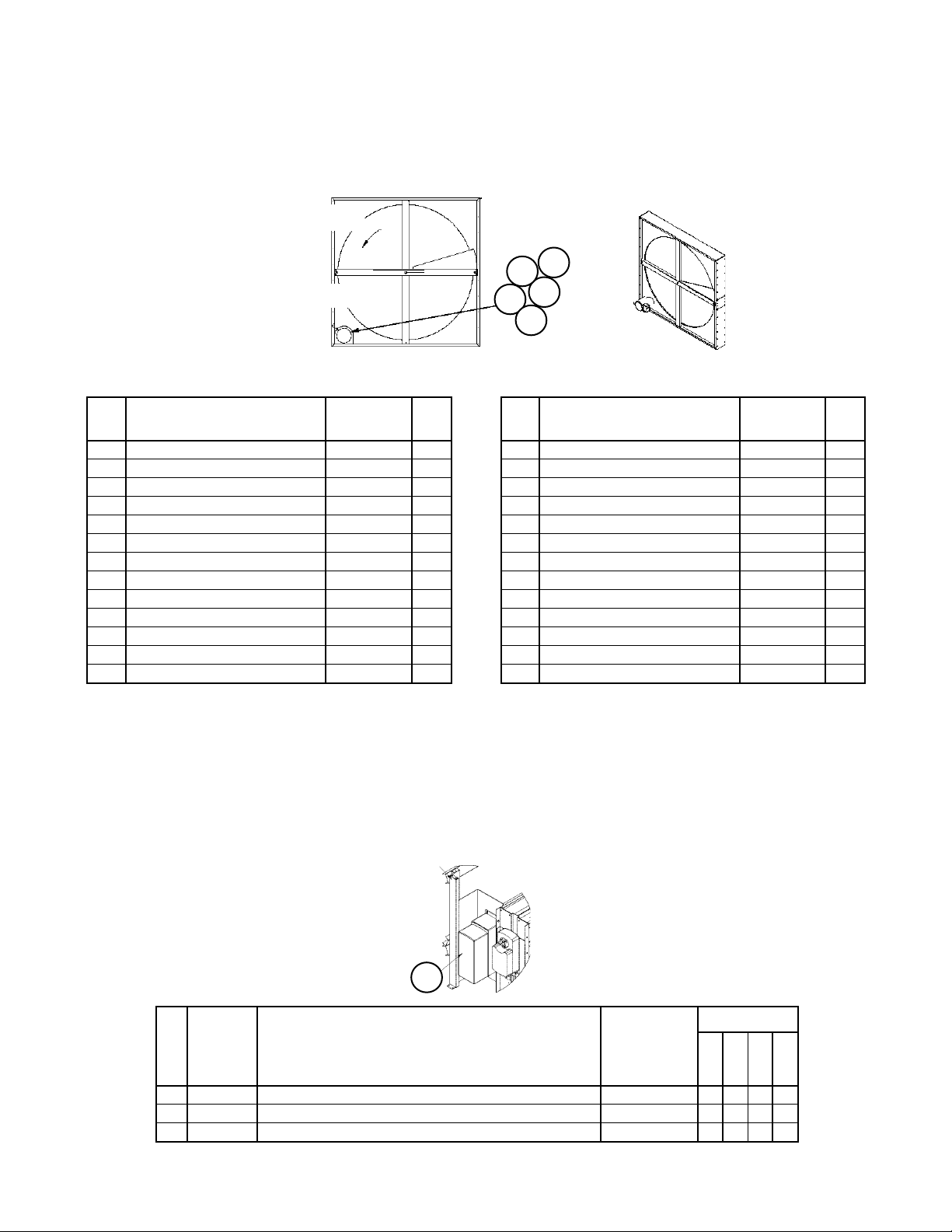
Section A2- Outdoor/Return/Heat Recovery Air Section
Heat Recovery— Enthalpy— Wheel Detail (Ref. #160)
Wheel, Motor, Drive Components, Seals
Outdoor Air Out (Supply)
165
164
Exhaust Air In (Return)
161
163
162
Low Air Flow ERC (Code 20= 3E or 5E)- 6” Wheel
Ref Part Part Qty.
No. Description Number
Wheel Assy- Complete 1
208/230/460V 113073801 1
575V 113087901 1
Segmented Wheel 2 300043261 1
161 Motor
208/230/460V 300043259 1
575V 300043263 1
162 Sheave 111048001 1
163 Bearing 300043258 2
164 Shaft 300043265 1
165 Belt 300043249 1
N/S Inner Seal 300043252 2
N/S Outer Seal 300043252 3
N/S= Not Shown on diagram.
1
Includes motor, shaft, belt etc.
2
If a replacement wheel is required, it is suggested that this part number be used. The segmented wheel ships disassembled which
allows for easier shipping and installation.
High Air Flow ERC (Code 20= 4E or 6E)- 12” Wheel
Ref Part Part Qty.
No. Description Number
Wheel Assy- Complete 1
208/230/460V 113073901 1
575V 113088001 1
Segmented Wheel 2 300043262 1
161 Motor
208/230/460V 300043259 1
575V 300043263 1
162 Sheave 300043260 1
163 Bearing 300043258 2
164 Shaft 300043266 1
165 Belt 300043249 1
N/S Inner Seal 300043252 2
N/S Outer Seal 300043252 3
Section A2- Outdoor/Return/Heat Recovery Air Section
AFD60 Frost Protection Inverter (Code 24= F)
3
Voltage
Ref Sch Part Part
208V
230V
460V
575V
No Sym Description Number
3 AFD60 Inverter 112046014 1 1
AFD60 Inverter 112046001 1
AFD60 Inverter 111195201 1
RoofPak Singlezone; RPS,RDT,RFS,RCS 045-079 “D” Rev. U 07/12 RPL 700013700 / Page 43
Page 44
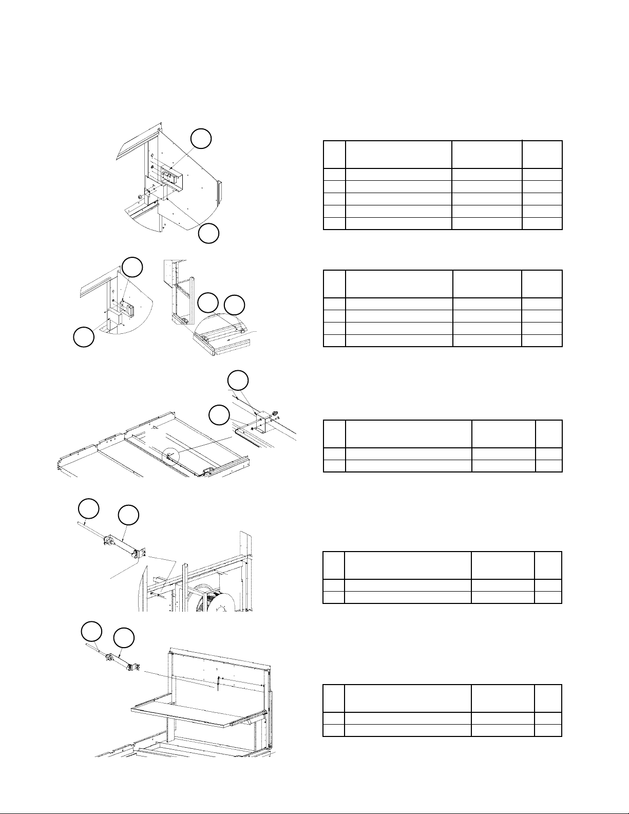
Section A2- Outdoor/Return/Heat Recovery Air Section
Section Mounted Controls
OAE, RAE, RAT, EAT, LAT
OA Opening
OAE
OA Opening
341
347
RA
Open-
ing
410
400
OA Opening
342
Deck Panel
200
348
184
RAE
RA Opening
OAE- Mechanical Enthalpy (Code 17= Y*)
Ref Part Part
No. Description Number Qty.
400 Mount- OAE Enthalpy 055800101 1
410 Enthalpy Assembly
(Knob & Control) 055740691 1
Knob only 026215500 1
Control OAE only 030706702 1
OAE & RAE Differential Enthalpy (Code 17= C*)
Ref Part Part
No. Description Number Qty.
341 Cover- OAE Enthalpy 111075801 1
342 Mount- RAE Enthalpy 055732301 1
347 Control- OAE 049262201 1
348 Control- RAE 049262202 1
RAT- Outdoor Air Temperature Sensor
Ref Part Part
No. Description Number Qty.
184 Support- RATS 111077601 1
200 RA Sensor- RAT 193414602 1
500
422
EAT- Outdoor Air Temperature Sensor
Ref Part Part
Return
Fan
No. Description Number Qty.
422 Support- EATS 111077601 1
500 RA Sensor- EAT 193414602 1
600
582
LAT- Leaving Air Temperature Sensor
Ref Part Part
No. Description Number Qty.
582 Support- LATS 111078001 1
600 Sensor- LAT 193414602 1
RoofPak Singlezone; RPS,RDT,RFS,RCS 045-079 “D” Rev. U 07/12 RPL 700013700 / Page 44
Page 45

Section A2- Outdoor/Return/Heat Recovery Air Section
Section Mounted Controls
SD2, HUM1, LT11, S11, REC11
Heat Wheel
RA Opening
RATS
RA Opening
596
597
230
227
Deck
Panel
SD2- Return Air Smoke Detector
C16= 1 or 3
Ref Part Part
No. Description Number Qty.
227 Support- SD2 111079701 1
230 Smoke Detector SD2 098873101 1
HUM1- Humidistat (units with frost protection)
Code 17= F
Ref Part Part
No. Description Number Qty.
596 Support- HUM1 111078101 1
597 Humidistat HUM1 067295001 1
85
84
LT11- Return Fan Light/S11- Return Fan Light
Switch/ REC11- Return Fan Light Receptacle
C49= E or F
Ref Part Part
No. Description Number Qty.
84 Light Fixture 042229500 1
85 Bulb- LT11 065492402 1
88 Light Switch- S11 065492201 1
88 89
RoofPak Singlezone; RPS,RDT,RFS,RCS 045-079 “D” Rev. U 07/12 RPL 700013700 / Page 45
89 Receptacle- REC11 030187000 1
Page 46

Section B- Draw-Thru Filter/Blank Section
➩
Primary Codes that pertain: 25
Additional Codes that pertain: 06, 19, 20
Code 25 determines all of the section characteristics. If the first digit of Code 25= A, D or E the filters are in an angular
rack, if the first digit= F, G or H the filters are in a flat rack, if the first digit= S, T or V the filters are in a staggered rack,
and If the first digit= B or C there is a blank section. If the second digit= Y there are no filters, if the second digit= A
there are throwaway filters, if the second digit= B there are 30% eff. filters and if the second digit= C there are 30%
eff. filters with antimicrobial Intersept. If the second digit= D there are 65% eff. filters, if the second digit= E there are
95% eff. filters and if the second digit= G there are 95% eff. filters with antimicrobial Intersept.
Code 06 determines the final assembly panel part numbers.
Codes 19 and 20 determine the Return Air section which has an effect on the final assembly panels.
This section pertains to the RPS, RFS or RDT, but not the RCS.
Notes
Section Mounted Controls
PC5, LT13, S13, REC13
Controls PC5
65
84 85
88 89
Ref. Part Part Qty.
No. Description Number
65 PC5 Pressure Ctl 065493801 1
LT13- Filter Section Light/S13- Filter Section
Light Switch/ REC13- Filter Section Receptacle
C49= E or F
Ref Part Part
No. Description Number Qty.
84 Light Fixture 055737501 1
85 Bulb- LT13 065492402 1
88 Light Switch- S13 065492201 1
89 Receptacle- REC13 030187000 1
RoofPak Singlezone; RPS,RDT,RFS,RCS 045-079 “D” Rev. U 07/12 RPL 700013700 / Page 46
Page 47

Section B- Draw-Thru Filter/Blank Section
Filters
Angular Filter Rack- Code 25= AA, AB, AC, DB, DC, EB, EC
Air
Flow
4
14
14
Ref. Part Code Part Qty.
No. Description 25= Number
4 Filter- Throwaway 1 AA 000016100 21
Filter- 30% Eff. Throwaway 1 *B 031298002 21
4
4
Filter- 30% Eff w/Intersept 1 *C 111046306 21
5 Filter- Throwaway 2 AA 000011700 7
Filter- 30% Eff. Throwaway 2 *B 031298001 7
5
8
Filter- 30% Eff w/Intersept 2 *C 111046305 7
8 Stop, Filter 011484101 7
14 Angle Assembly 3 056077301 28
* First digit of code may be A, D or E.
1
Filter size= 16 x 25 x 2.
2
Filter size= 16 x 20 x 2.
3
Optional- angle is mounted on leaving air side.
Flat Filter Rack- Code 25= FD, FE, FG, GD, GE, GG, HD, HE, HG
106A
107A
106
107
104
104A
105
Ref. Part Code Part Qty.
No. Description 25= Number
104 Filter- 65% Eff. Cartridge 4 *D 065810704 8
Filter- 95% Eff Cartridge 4 *E 065810702 8
104A Gasket- Filter 021768924 8
105 Filter- 65% Eff. Cartridge 5 *D 065810703 4
Filter- 95% Eff Cartridge 5 *E 065810701 4
105A Gasket- Filter 021768912 4
105A
106 Pre Filter 6 *D or *E 111046101 8
106A Gasket- Pre Filter 111051900 16ft
107 Pre Filter 7 *D or *E 111046103 4
107A Gasket- Pre Filter 111051900 8 ft
* First digit of code, may be F, G or H.
4
Filter size= 24 x 24 x 12. 5 Filter size= 12 x 24 x 12.
6
Filter size= 24 x 24 x 2.
7
Filter size= 12 x 24 x 2.
RoofPak Singlezone; RPS,RDT,RFS,RCS 045-079 “D” Rev. U 07/12 RPL 700013700 / Page 47
Page 48

Section B- Draw-Thru Filter/Blank Section
Filters, Continued & Air Blender Section Components
Filters
Staggered Filter Rack- Code 25= SD, SE, SG, TD, TE, TG, VD, VE, VG
Ref. Part Code Part Qty.
204A
No. Description 25= Number
204 Filter- 65% Eff. Cartridge 4 *D 065810704 8
Filter- 95% Eff Cartridge 4 *E 065810702 8
204A Gasket- Filter 021768924 8
205 Filter- 65% Eff. Cartridge 5 *D 065810703 8
Filter- 95% Eff Cartridge 5 *E 065810701 8
205A Gasket- Filter 021768912 8
206 Pre Filter 6 *D or *E 111046101 8
205A
206A Gasket- Pre Filter 111051900 16ft
207 Pre Filter 7 *D or *E 111046103 8
207A Gasket- Pre Filter 111051900 16ft
* First digit of code, may be S, T or V.
4
Filter size= 24 x 24 x 12. 5 Filter size= 12 x 24 x 12.
6
Filter size= 24 x 24 x 2.
7
Filter size= 12 x 24 x 2.
207A
207
206
204
205
204
204A
206A
Air Blender Section Components
(C25= DB, DC, EE, EC, GD, GE, GG, HD, HE, HG, TD, TE, TG, VD, VE, VG)
Ref. Part Code Part Qty.
No. Description 25= Number
65 Panel- Access 251802801 2
68 Air Blender
Low CFM GD, GE, DB, DC 205139534 2
High CFM HD, HE, EB, EC 205139538 2
75
68
68
65
RoofPak Singlezone; RPS,RDT,RFS,RCS 045-079 “D” Rev. U 07/12 RPL 700013700 / Page 48
75 Plate- Economizer Linkage Access 059385501 1
Page 49

Section C- Draw-Thru Blank Access Section
or Separate Inverter Section
➩
Primary Codes that pertain: 26, 14, 15
Additional Codes that pertain: 06
Code 26 determines if a section is installed and if so, the size of the section. If Code 26= S there is a 48” blank
section. If Code 26= Y, there is no section.
Code 06 determines the liners and insulation, and will affect the final assembly panels. For sheet metal components
that make up the Blank compartment, contact Daikin McQuay Parts to insure correct liners, insulation and
hardware are ordered.
Codes 14 & 15 determine if the unit has inverter(s) and if so where they are installed. If Code 14= 1, 2 or 4 AND Code
26= S, there is a separate inverter section. If Code 14= 3, 5, 6, 7, 8 or 9, the inverter(s) are installed in the Supply
Air Section. If Code 14= Y, there are no inverters. Code 15 determines the inverter type. The Inverter with Bypass
is shown below. All components pertaining to the Inverter are listed in the Supply Air Section (Section F).
This section pertains to the RPS, RFS or RDT, but not the RCS.
Notes
Return Air Inverter
(AFD20)
Overload
(OL10- Supply Air)
(OL20- Return Air)
Power Block
(PB10- Supply Air)
(PB20- Return Air)
Supply Air Inverter
(AFD10)
Contactor
(M30A/M30B- Supply Air)
(M40A/M40B- Return Air)
Section C- Draw-Thru Blank Access Section
or Separate Inverter Section
Unit Mounted Controls
LT17- Filter Section Light/S17- Filter Section
84 85
88 89
Light Switch/ REC17- Filter Section Receptacle
Ref Part Part
No. Description Number Qty.
84 Light Fixture 042229500 1
85 Bulb- LT17 065492402 1
88 Light Switch- S17 065492201 1
89 Receptacle- REC17 030187000 1
RoofPak Singlezone; RPS,RDT,RFS,RCS 045-079 “D” Rev. U 07/12 RPL 700013700 / Page 49
Page 50

Section D- Draw-Thru Cooling Section
Notes
➩
Primary Codes that pertain: 03, 27, 28
Additional Codes that pertain: 06
Code 03 determines the DX cooling coil size. If Code 03= S there is a small face area coil (24” section), and if Code
03= L it is a large face area coil (48” section).
Code 27 determines if there is a Section D. If Code 27= YYYY, then there is no section (for RPS or RFS units this
indicates that the cooling coil is in the Blow-Thru position, RDT units always have a section D). If the code is CYYY
or CYYS then there is a unit cooling coil and drain pan (the “S” means the drain pan is stainless steel, a “Y” in the
fourth position indicates that the pan is galvanized). If Code 27= DYYY or DYYS, then the section contains only a
drain pan (not an option for RDT units).
Code 28 will apply only if Code 27= CYYY or CYYS, and determines the coil characteristics.
Code 06 determines the liners and insulation, and will affect the final assembly panels. For sheet metal components
that make up the Draw-Thru Cooling Section, contact Daikin McQuay Parts to insure correct liners, insulation
and hardware are ordered.
NOTE: The drawings and components listed in this section also apply to Section I—
Blow-Thru Cooling Section- RPS or RFS units.
RoofPak Singlezone; RPS,RDT,RFS,RCS 045-079 “D” Rev. U 07/12 RPL 700013700 / Page 50
Page 51

Section D- Draw-Thru Cooling Section
Evaporator Coils, Drain Pans, Gasketing
24” Section, Small Face Coils- Code 03= S
Small Face Area Coil
24” Section
Code 03= S
3
39
43
13
10
Ref. Part Part Qty.
No. Description Number
3 Coil Contact Daikin McQuay Parts
10 Drain Pan
Galvanized C27= CYYY 056267751 1
Stainless C27= CYYS 056267752 1
13 Pan- Auxiliary
Galvanized C27= CYYY 055926503 1
Stainless C27= CYYS 057356801 1
39 Gasket 049263200 6’
43 Gasket 021911422 2
48” Section, Large Face Coils- Code 03= L— Unit Sizes 050 - 075 only
Large Face Area Coil
48” Section
Code 03= L
3
37
10
4
43
11
12
13
39
Ref. Part Part Qty.
No. Description Number
3 Coil- Lower Contact Daikin McQuay Parts
4 Coil- Upper Contact Daikin McQuay Parts
10 Drain Pan
Galvanized C27= CYYY 056267755 1
39
Stainless C27= CYYS 056267756 1
11 Drain Pan
Galvanized C27= CYYY 096235001 1
Stainless C27= CYYS 055531354 1
12 Pan- Liner 055531202 1
13 Pan- Auxiliary 056271401 1
37 Gasket 056003501 120
39 Gasket 049263200 7’
43 Gasket 021911422 4
RoofPak Singlezone; RPS,RDT,RFS,RCS 045-079 “D” Rev. U 07/12 RPL 700013700 / Page 51
Page 52

Section E- 48” Spacer Section & Draw-Thru Heat Section
➩
Notes
Section E- 48” Spacer Section
Notes
Primary Codes that pertain: 30
Additional Codes that pertain: 06
Code 30 determines all of the section characteristics. If Code 26= BBBBBB there is a 48” blank section. If Code
30= YYYYYY, there is no section.
Code 06 determines the liners and insulation, and will affect the final assembly panels. For sheet metal components
that make up the 48” Spacer Section, contact Daikin McQuay Parts to insure correct liners, insulation and
hardware are ordered.
Section E- Draw-Thru Heat Section
RDT Units
Notes
Primary Codes that pertain: 04, 30
Additional Codes that pertain: 06
Code 04 determines what type of heat. Draw- Thru Heat units are normally hydronic heat only; Steam (C04=S) or
Hot Water (C04= H). NOTE: There are a few Draw-Thru Electric Heat units. See Section G [Blow Thru Heat]
for all Electric Heat components).
Code 30 determines the coil and associated valve characteristics.
Code 06 determines the liners and insulation, and will affect the final assembly panels. For sheet metal components
that make up the Draw-Thru Heat Section, contact Daikin McQuay Parts to insure correct liners, insulation
and hardware are ordered.
Section Mounted Controls
LT18, REC18, S18- Section Mounted Light
LT18- Return Fan Light/S18- Return Fan Light
284 285
288 289
Switch/ REC18- Return Fan Light Receptacle
Ref Part Part
No. Description Number Qty.
284 Light Fixture 042229500 1
285 Bulb- LT18 065492402 1
288 Light Switch- S18 065492201 1
289 Receptacle- REC18 030187000 1
RoofPak Singlezone; RPS,RDT,RFS,RCS 045-079 “D” Rev. U 07/12 RPL 700013700 / Page 52
Page 53

Section E- Draw-Thru Heat Section
RDT Units
Hot Water or Steam Coil Heat, Mixing Valves and Actuator (VM1)
Code 30 first 3 digits = S11, S12, S13, S14, W11, W12, W22
Coil Location
3
2
Ref Sch. Part Code Coil Coil Part
No. Sym. Description 30= Type Height Number Qty.
2 Steam Heat Coil- Bottom S11*** 5JA0601H 30” 056053021 1
Steam Heat Coil- Bottom S12*** 5JA1201H 30” 056053022 1
Steam Heat Coil- Bottom S13*** 5JA0602C 30” 056053023 1
Steam Heat Coil- Bottom S14*** 5JA1202C 30” 056053024 1
Hot Water Heat Coil- Bottom W11*** 5WH0901H 30” 056053025 1
Hot Water Heat Coil- Bottom W22*** 5WS0902C 30” 056053026 1
3 Steam Heat Coil- Top S11*** 5JA0601H 27” 056053031 1
Steam Heat Coil- Top S12*** 5JA1201H 27” 056053032 1
Steam Heat Coil- Top S13*** 5JA0602C 27” 056053013 1
Steam Heat Coil- Top S14*** 5JA1202C 27” 056053014 1
Hot Water Heat Coil- Top W11*** 5WH0901H 27” 056053035 1
Hot Water Heat Coil- Top W22*** 5WS0902C 27” 056053016 1
63 VM1 Actuator- 120V *****E All All 059999804 1
64 Linkage- 1.25”, 1.50” or 2.00” Valve *****E All All 049762401 1
Linkage- 2.50” or 3.00” Valve *****E All All 049762403 1
65 Valve, 2 Way— Steam Heat
1.25” S**E2* 5JA All 049762502 1
1.50” S**F2* 5JA All 049762503 1
2.00” S**G2* 5JA All 049762504 1
2.50” S**H2* 5JA All 049762505 1
3.00” 1 S**J2* 5JA All 049762506 1
Valve, 3 Way— Hot Water Heat
1.25” W**E3* 5WH, 5WS All 047936505 1
1.50” W**F3* 5WH, 5WS All 047936501 1
2.00” W**G3* 5WH, 5WS All 047936502 1
2.50” W**H3* 5WH, 5WS All 047936506 1
3.00” 2 W**J3* 5WH, 5WS All 047936503 1
1
Steam Heat 3.00” valve has a flange gasket p/n: 031315900.
2
Hot Water Heat 3.00” valve has a flange gasket p/n: 031316000.
Mixing Valve Detail
63
64
65
RoofPak Singlezone; RPS,RDT,RFS,RCS 045-079 “D” Rev. U 07/12 RPL 700013700 / Page 53
Page 54

Section F- Supply Air Section
Notes
➩
Primary Codes that pertain: 31, 32, 33, 12, 14, 15, 40
Additional Codes that pertain: 04, 06, 34, 48
Code 31 determines the fan size and type, Code 32 determines the motor horsepower and type, and Code 33
determines the drive selection. The drive components (fan sheave, motor sheave, belt, and fan bushing) are not
listed as they are unique to the unit. The drive components (fan sheave, motor sheave, belt, and fan bushing)
are not listed as they are unique to the unit. If a drive component is required you may use the number from
the part and cross reference it with the Drive Components Cross Reference form number: 571006, or contact
Daikin McQuay Parts to ensure that the needed part(s) are correctly identified. The motors range from 3 - 50
horsepower.
Code 04 and Code 34 determine the heat type, which can affect the final assembly part numbers, the location of
the discharge plenum, as well as the section- installed controls.
Code 06 determines the liners and insulation, and will affect the final assembly panels. For sheet metal components
that make up the Supply Air Section, contact Daikin McQuay Parts to insure correct liners, insulation and
hardware are ordered.
Code 12 determines the location of the unit’s main control box. RDT units have main control boxes in the Supply
Air section.
Code 40 determines the discharge plenum configuration. The discharge plenum is located in Section F when the
section is bolted directly to the condenser (Section M). RDT units always have the discharge plenum located in Section
F. If Code 40= BE, there is an isolation damper with actuator ACT5. The damper is detailed in Section K.
Code 48 determines if the unit is equipped with Hot Gas Reheat and/or IBC seismic construction. If Code 48 is I
then Code 31 must be ***1 or ***3.
Codes 14 & 15 determine if the unit has inverter(s) and if so where they are installed. If Code 14= 3, 5, 6, 7, 8 or 9,
the inverter(s) are installed in the Supply Air Section. If Code 14= 1, 2 or 4 AND Code 25= S, there is a separate
inverter section. If Code 14= Y, there are no inverters. Code 15 determines the inverter type. All components
pertaining to the Inverter are listed in this section.
This section pertains to the RPS, RFS or RDT, but not the RCS.
RoofPak Singlezone; RPS,RDT,RFS,RCS 045-079 “D” Rev. U 07/12 RPL 700013700 / Page 54
Page 55
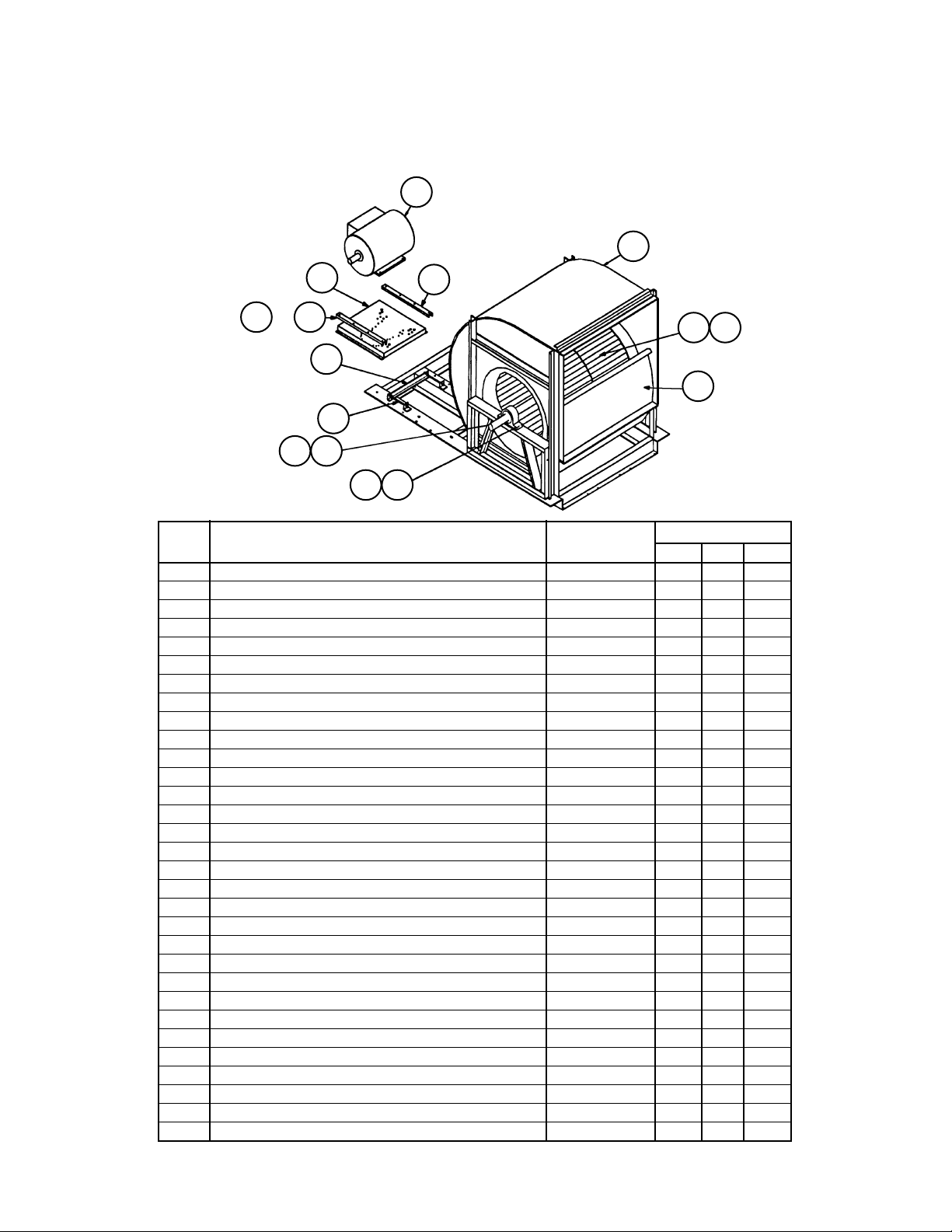
Section F- Supply Air Section
Forward Curved Fans
Low Pressure- FCLP- Code 31= 27F*, 30F* or 33F*
1
2
15
or
1817
16
5
11
22
Ref. Part Part Fan Size
No. Description Number 27” 30” 33”
1 Motor- see Supply Air Fan Motor Section
2 Housing- Blower Assy 055527713 1
Housing- Blower Assy 055527714 1
Housing- Blower Assy 055527715 1
3 Wheel Assembly 024061101 1
Wheel Assembly 024061103 1
Wheel Assembly 012725735 1
5 Screw Adjust Assy 055528202 1 1 1
11 Shaft- 1.688” Dia. 055599601 1
Shaft- 1.937” Dia. 055582801 1
Shaft- 2.188” Dia. 055582701 1
12 Plate, Cutoff 030030102 1
Plate, Cutoff 030030103 1
Plate, Cutoff 029309800 1
15 Mount Assy- Motor 056104501 1 1 1
16 Angle- Motor Mount 055514201 1 1 1
17 Hold Down 041272900 1 1
Hold Down 041272900 1
18 Angle- Clamping 055576601 1 1 1
20 Plate- Shim 055599701 4
Plate- Shim 055599801 4
Plate- Shim- 032422700 2
21 Key- Fan, 4.75” Long 023221409 1
Key- Fan, 4.75” Long 023221508 1
Key- Fan, 4.75” Long 023221508 1
22 Key- Sheave, 6.00” Long 023221416 1
Key- Sheave, 8.50” Long 023221516 1
Key- Sheave, 6.50” Long 023221515 1
23 Bearing- Ball- 1.687” 020648602 2
Bearing- Ball- 1.937” 020648603 2
Bearing- Ball- 2.187” 020648604 2
17
31221
2023
RoofPak Singlezone; RPS,RDT,RFS,RCS 045-079 “D” Rev. U 07/12 RPL 700013700 / Page 55
Page 56
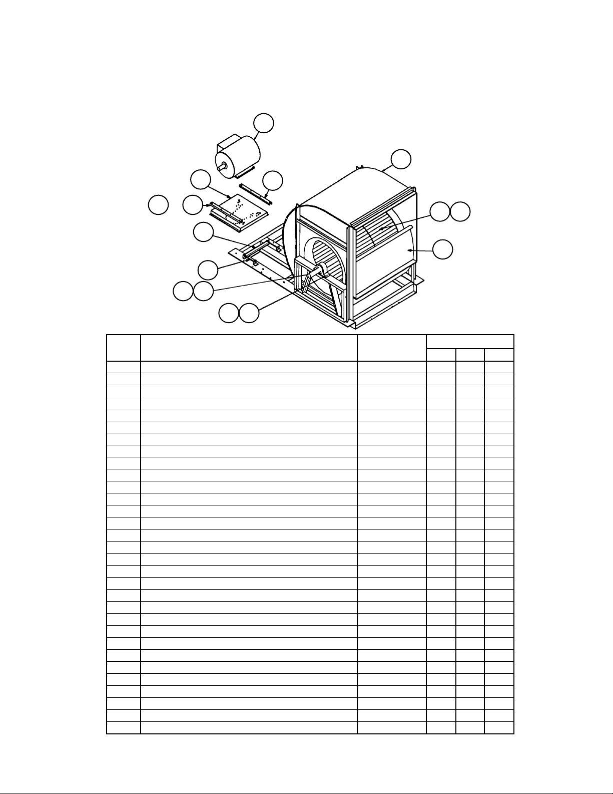
Section F- Supply Air Section
Forward Curved Fans
High Pressure- FCMP- Code 31= 27M*, 30M* or 33M*
1
2
15
or
1817
16
5
11
22
Ref. Part Part Fan Size
No. Description Number 27” 30” 33”
1 Motor- see Supply Air Fan Motor Section
2 Housing- Blower Assy 055527713 1
Housing- Blower Assy 055527714 1
Housing- Blower Assy 055527715 1
3 Wheel Assembly 024061102 1
Wheel Assembly 012727435 1
Wheel Assembly 012727939 1
5 Screw Adjust Assy 055528202 1 1 1
11 Shaft- 1.688” Dia. 055599601 1
Shaft- 2.176” Dia. 055683402 1
Shaft- 2.438” Dia. 055515701 1
12 Plate, Cutoff 030030102 1
Plate, Cutoff 030030103 1
Plate, Cutoff 029309800 1
15 Mount Assy- Motor 056104501 1 1 1
16 Angle- Motor Mount 055514201 1 1 1
17 Hold Down 041272900 1 1
Hold Down 041272900 1
18 Angle- Clamping 055576601 1 1
20 Plate- Shim 055599701 4
Plate- Shim 055683501 2
Plate- Shim 032422700 2
21 Key- Fan, 4.75” Long 023221409 1
Key- Fan, 4.75” Long 023221508 1
Key- Fan, 9.25” Long 023221614 1
22 Key- Sheave, 6.00” Long 023221416 1
Key- Sheave, 8.50” Long 023221516 1
Key- Sheave, 6.50” Long 023221610 1
23 Bearing- Ball- 1.687” 020648602 2
Bearing- Ball- 2.187” 020648604 2
Bearing- Ball- 2.437” 020648605 2
17
31221
2023
RoofPak Singlezone; RPS,RDT,RFS,RCS 045-079 “D” Rev. U 07/12 RPL 700013700 / Page 56
Page 57

Section F- Supply Air Section
Air Foil Fan- Double Width
Code 31= 27A1, 27A2, 27A3, 30A1, 30A2, 30A3, 33A1, 33A2 or 33A3
2
17
17
15
1
Ref. Part Part Fan Size
No Description Number 27” 30” 33”
1 Motor- see Supply Air Fan Motor Section
2 Housing Assy- Blower, w/o Inlet Vanes 055527701 1
Inlet Funnel Only 031940901 2
Housing Assy- Blower 055527702 1
Inlet Funnel Only 031940902 2
Housing Assy- Blower 055527703 1
Inlet Funnel Only 031940903 2
3 Wheel, Fan- Single Inlet Single Width CW 066543201 1
Wheel, Fan- Single Inlet Single Width CW 066543203 1
Wheel, Fan- Single Inlet Single Width CW 066543205 1
4 Wheel, Fan- Single Inlet Single Width CCW 066543202 1
Wheel, Fan- Single Inlet Single Width CCW 066543204 1
Wheel, Fan- Single Inlet Single Width CCW 066543206 1
5 Screw Adjust Assembly 055528202 2 2 2
11 Shaft- 2.188” Diameter 055599502 1
Shaft- 2.438” Diameter 055582902 1
Shaft- 2.438” Diameter 055515702 1
15 Motor Mount Assembly 056104501 1 1 1
16 Angle- Motor Mount 055514201 1 1 1
17 Holddown 041272900 1 1 2
18 Angle, Clamping 055576601 1 1 1
21 Key- Fan 9.25” Long X 1/2” Diameter 023221517 1
Key- Fan 9.25” Long X 5/8” Diameter 023221614 1
Key- Fan 4.75” Long X 5/8” Diameter 023221606 2
22 Key- Sheave 6.50” Long X 1/2” Diameter 023221515 1
Key- Sheave 6.50” Long X 5/8” Diameter 023221610 1 1
25 Bearing- Ball 2.187” Bore 020648604 2
Bearing- Ball 2.437” Bore 020648605 2 2
18
16
321 4
Wheel Detail
(facing discharge)
11
25
22
5
RoofPak Singlezone; RPS,RDT,RFS,RCS 045-079 “D” Rev. U 07/12 RPL 700013700 / Page 57
Page 58

Section F- Supply Air Section
Air Foil Fan- Single Width- RDT Units
Code 31= 40B1, 40B2, 40B3, 44B1, 44B2, 44B3
24
25
26
1
15
27
22
38
4
11
21
3
16
5
17
Ref. Part Part Fan Size
No. Description Number 40” 44”
1 Motor- see Supply Air Fan Motor Section
3 Wheel, Fan- Single Inlet/Single Width 066543243 1
Wheel, Fan- Single Inlet/Single Width 110942010 1
4 Inlet Funnel Assembly 031940905 1
Inlet Funnel Assembly 110941810 1
5 Screw Adjust Assembly 055528203 2 2
11 Shaft- 2.188” Diameter 055615902 1
Shaft- 2.438” Diameter 055534702 1
15 Mount Assembly-Motor 056104501 1 1
16 Angle -Motor Mount 055514201 1 1
17 Angle, Clamping 055512701 2 2
21 Key- Fan, 4.25” Long X 1/2” Diameter 023221519 1
Key- Fan, 6.50” Long X 5/8” Diameter 023221610 1
22 Key- Fan, 5.50” Long X 1/2” Diameter 023221513 1
Key- Fan, 5.50” Long X 5/8” Diameter 023221607 1
24 Tubing- Plastic 021136790 1
Tubing- Plastic 021136795 1
25 Bearing- Ball, 2.187” Bore 020648606 1
Bearing- Ball, 2.437” Bore 020648605 1
26 Fitting- 1/4” OD X 1/8” MPT 027674000 1 1
27 Fitting- 1/4” OD X 1/8” FPT 027674100 1 1
38 Bearing- Ball, 2.187” Bore 020648606 1
Bearing- Ball, 2.437” Bore 020648605 1
RoofPak Singlezone; RPS,RDT,RFS,RCS 045-079 “D” Rev. U 07/12 RPL 700013700 / Page 58
Page 59

92
93
89
81
Rubber Mounts
Section F- Supply Air Section
Fan Mounts- 27” Forward Curved Fan
Code 31= 27F1, 27F2, 27F3, 27M1, 27M2, 27M3
Mount Locations
or
61161
or
63163
or
16262
or
16464
Rubber Mounts (Code 31= 27F1 or 27M1)
91
61 62
63
21
91
64
Ref. Fan Motor Part Part Qty.
No. HP Description Number
21 All Channel- Mount Support 098316001 4
61 3 - 10 Rubber Mount- Black 021639704 1
15 - 50 Rubber Mount- Red 021639701 1
62 All Rubber Mount- Black 021639704 1
63 3, 5 Rubber Mount- Black 021639704 1
7.5 - 50 Rubber Mount- Red 021639701 1
64 3 -7.5, 20-50 Rubber Mount- Red 021639701 1
10, 15 Rubber Mount- Black 021639704 1
81 All Nut 059992201 8
89 All Screw 112047201 8
91 All Nut- 1/2-13 032333305 12
92 All Screw- Cap, 1/2-13 X 1” 040499501 8
93 All Washer- Plain, 1/2” 048164812 8
188
189
181
Spring Mounts
121
161 162
163
164
Spring Mounts (Code 31= 27F2 or 27M2) and
Seismic Spring (Code 31= 27F3 or 27M3)
Ref. Fan Motor Part Part Qty.
No. HP Description Number
121 All Mount
Spring (C31= 27*2) 251783201 4
Seismic (C31= 27*3) 251783301 4
161 5 - 10 Spring Mount- Purple 251784701 1
15 - 30 Spring Mount- Brown 251784801 1
40, 50 Spring Mount- Red 251784901 1
162 All Spring Mount- Purple 251784701 1
163 5 Spring Mount- Purple 251784701 1
7.5, 10 Spring Mount- Brown 251784801 1
15 - 30 Spring Mount- Red 251784901 1
40, 50 Spring Mount- Red/Black 251785001 1
164 All Spring Mount- Brown 251784801 1
181 All Nut
Spring (C31= 27*2) 059992201 12
Seismic (C31= 27*3) 111056301 20
188 All Nut 040500002 4
189 All Screw
Spring (C31= 27*2) 112047201 12
Seismic (C31= 27*3) 112047201 20
RoofPak Singlezone; RPS,RDT,RFS,RCS 045-079 “D” Rev. U 07/12 RPL 700013700 / Page 59
Page 60

161
or
61
92
93
89
81
Rubber Mounts
Section F- Supply Air Section
Fan Mounts- 30” Forward Curved Fan
Code 31= 30F1, 30F2, 30F3, 30M1, 30M2, 30M3
Rubber Mounts (Code 31= 30F1 or 30M1)
91
61 62
63
64
21
91
Mount Locations
Ref. Fan Motor Part Part Qty.
No. HP Description Number
21 All Channel- Mount Support 098316001 4
61 3, 5 Rubber Mount- Black 021639704 1
10 - 50 Rubber Mount- Red 021639701 1
62 All Rubber Mount- Black 021639704 1
63 3 - 30 Rubber Mount- Black 021639701 1
40, 50 Rubber Mount- Green 021639703 1
64 3- 10, 20- 50 Rubber Mount- Red 021639701 1
15 Rubber Mount- Black 021639704 1
81 All Nut 059992201 8
89 All Screw 112047201 8
91 All Nut- 1/2-13 032333305 12
92 All Screw- Cap, 1/2-13 X 1” 040499501 8
93 All Washer- Plain, 1/2” 048164812 8
63
or
163
188
189
181
Spring Mounts
62
64
121
161 162
163
or
or
164
162
164
Spring Mounts (Code 31= 30F2 or 30M2) and
Seismic Spring (Code 31= 30F3 or 30M3)
Ref. Fan Motor Part Part Qty.
No. HP Description Number
121 All Mount
Spring (C31= 30*2) 251783201 4
Seismic (C31= 30*3) 251783301 4
161 5 Spring Mount- Purple 251784701 1
7.5 - 15 Spring Mount- Brown 251784801 1
20 - 50 Spring Mount- Red 251784901 1
162 5 - 20 Spring Mount- Brown 251784801 1
25 - 50 Spring Mount- Purple 251784701 1
163 5, 7.5 Spring Mount- Brown 251784801 1
10 - 20 Spring Mount- Red 251784901 1
25 - 50 Spring Mount- Red/Black 251785001 1
164 5 - 15 Spring Mount- Brown 251784801 1
20 - 50 Spring Mount- Red 251784901 1
181 All Nut
Spring (C31= 30*2) 059992201 12
Seismic (C31= 30*3) 111056301 20
188 All Nut 040500002 4
189 All Screw
Spring (C31= 30*2) 112047201 12
Seismic (C31= 30*3) 112047201 20
RoofPak Singlezone; RPS,RDT,RFS,RCS 045-079 “D” Rev. U 07/12 RPL 700013700 / Page 60
Page 61

Section F- Supply Air Section
Fan Mounts- 33” Forward Curved Fan
Code 31= 33F1, 33F2, 33F3, 33M1, 33M2, 33M3
Mount Locations
or
61161
or
63163
or
16262
or
16464
92
93
89
81
Rubber Mounts
188
189
181
Spring Mounts
91
61 62
91
121
161 162
163
63
21
164
64
Rubber Mounts (Code 31= 33F1 or 33M1)
Ref. Fan Motor Part Part Qty.
No. HP Description Number
21 All Channel- Mount Support 098316001 4
61 3 - 7.5 Rubber Mount- Black 021639704 1
10 - 50 Rubber Mount- Red 021639701 1
62 All Rubber Mount- Red 021639701 1
63 3 - 40 Rubber Mount- Red 021639701 1
50 Rubber Mount- Green 021639703 1
64 All Rubber Mount- Red 021639701 1
81 All Nut 059992201 8
89 All Screw 112047201 8
91 All Nut- 1/2-13 032333305 12
92 All Screw- Cap, 1/2-13 X 1” 040499501 8
93 All Washer- Plain, 1/2” 048164812 8
Spring Mounts (Code 31= 33F2 or 33M2) and
Seismic Spring (Code 31= 33F3 or 33M3)
Ref. Fan Motor Part Part Qty.
No. HP Description Number
121 All Mount
Spring (C31= 33*2) 251783201 4
Seismic (C31= 33*3) 251783301 4
161 5, 7.5 Spring Mount- Purple 251784701 1
10 - 20 Spring Mount- Brown 251784801 1
25 - 50 Spring Mount- Red 251784901 1
162 All Spring Mount- Purple 251784701 1
163 5 - 10 Spring Mount- Brown 251784801 1
15, 20 Spring Mount- Red 251784901 1
25 - 50 Spring Mount- Red/Black 251785001 1
164 All Spring Mount- Brown 251784801 1
181 All Nut
Spring (C31= 33*2) 059992201 12
Seismic (C31= 33*3) 111056301 20
188 All Nut 040500002 4
189 All Screw
Spring (C31= 33*2) 112047201 12
Seismic (C31= 33*3) 112047201 20
RoofPak Singlezone; RPS,RDT,RFS,RCS 045-079 “D” Rev. U 07/12 RPL 700013700 / Page 61
Page 62

92
93
89
81
Rubber Mounts
Section F- Supply Air Section
Fan Mounts- 27” Airfoil Double Width Fan
Code 31= 27A1, 27A2, 27A3
Rubber Mounts (Code 31= 27A1)
91
61 62
63
21
91
64
Ref. Fan Motor Part Part Qty.
No. HP Description Number
21 All Channel- Mount Support 098316001 4
61 3 - 10 Rubber Mount- Black 021639704 1
15 - 50 Rubber Mount- Red 021639701 1
62 All Rubber Mount- Black 021639704 1
63 3, 5, 10 Rubber Mount- Black 021639704 1
7.5, 15- 50 Rubber Mount- Red 021639701 1
64 3- 7.5, 15- 30 Rubber Mount- Black 021639704 1
10, 40, 50 Rubber Mount- Red 021639701 1
81 All Nut 059992201 8
89 All Screw 112047201 8
91 All Nut- 1/2-13 032333305 12
92 All Screw- Cap, 1/2-13 X 1” 040499501 8
93 All Washer- Plain, 1/2” 048164812 8
161
or
61
63
or
163
188
189
181
Spring Mounts
Mount Locations
162
or
62
164
or
64
121
161 162
163
164
Spring Mounts (Code 31= 27A2) and
Seismic Spring (Code 31= 27A3)
Ref. Fan Motor Part Part Qty.
No. HP Description Number
121 All Mount
Spring (C31= 27*2) 251783201 4
Seismic (C31= 27*3) 251783301 4
161 5 - 10 Spring Mount- Purple 251784701 1
15 - 30 Spring Mount- Brown 251784801 1
40, 50 Spring Mount- Red 251784901 1
162 All Spring Mount- Purple 251784701 1
163 5 Spring Mount- Purple 251784701 1
7.5, 10 Spring Mount- Brown 251784801 1
15 - 30 Spring Mount- Red 251784901 1
40, 50 Spring Mount- Red/Black 251785001 1
164 All Spring Mount- Brown 251784801 1
181 All Nut
Spring (C31= 27*2) 059992201 12
Seismic (C31= 27*3) 111056301 20
188 All Nut 040500002 4
189 All Screw
Spring (C31= 27*2) 112047201 12
Seismic (C31= 27*3) 112047201 20
RoofPak Singlezone; RPS,RDT,RFS,RCS 045-079 “D” Rev. U 07/12 RPL 700013700 / Page 62
Page 63

92
93
89
81
Rubber Mounts
Section F- Supply Air Section
Fan Mounts- 30” Airfoil Double Width Fan
Code 31= 30A1, 30A2, 30A3
Mount Locations
or
61161
or
63163
or
16262
or
16464
Rubber Mounts (Code 31= 30A1)
91
61 62
63
21
91
64
Ref. Fan Motor Part Part Qty.
No. HP Description Number
21 All Channel- Mount Support 098316001 4
61 3, 5 Rubber Mount- Black 021639704 1
7.5 - 50 Rubber Mount- Red 021639701 1
62 All Rubber Mount- Black 021639704 1
63 3 - 30 Rubber Mount- Red 021639701 1
40, 50 Rubber Mount- Green 021639703 1
64 3 - 15 Rubber Mount- Black 021639704 1
20 - 50 Rubber Mount- Red 021639701 1
81 All Nut 059992201 8
89 All Screw 112047201 8
91 All Nut- 1/2-13 032333305 12
92 All Screw- Cap, 1/2-13 X 1” 040499501 8
93 All Washer- Plain, 1/2” 048164812 8
Spring Mounts (Code 31= 30A2) and
Seismic Spring (Code 31= 30A3)
Ref. Fan Motor Part Part Qty.
No. HP Description Number
188
189
181
121
161 162
163
164
Spring Mounts
RoofPak Singlezone; RPS,RDT,RFS,RCS 045-079 “D” Rev. U 07/12 RPL 700013700 / Page 63
121 All Mount
Spring (C31= 30*2) 251783201 4
Seismic (C31= 30*3) 251783301 4
161 5 Spring Mount- Purple 251784701 1
7.5 - 20 Spring Mount- Brown 251784801 1
25 - 50 Spring Mount- Red 251784901 1
162 All Spring Mount- Purple 251784701 1
163 5, 7.5 Spring Mount- Brown 251784801 1
10 - 20 Spring Mount- Red 251784901 1
25 - 50 Spring Mount- Red/Black 251785001 1
164 All Spring Mount- Brown 251784801 1
181 All Nut
Spring (C31= 30*2) 059992201 12
Seismic (C31= 30*3) 111056301 20
188 All Nut 040500002 4
189 All Screw
Spring (C31= 30*2) 112047201 12
Seismic (C31= 30*3) 112047201 20
Page 64

161
or
61
92
93
89
81
Rubber Mounts
Section F- Supply Air Section
Fan Mounts- 33” Airfoil Double Width Fan
Code 31= 33A1, 33A2, 33A3
Rubber Mounts (Code 31= 33A1)
91
61 62
63
64
21
91
Mount Locations
Ref. Fan Motor Part Part Qty.
No. HP Description Number
21 All Channel- Mount Support 098316001 4
61 3 - 10 Rubber Mount- Black 021639704 1
15 - 50 Rubber Mount- Red 021639701 1
62 3, 5 Rubber Mount- Red 021639701 1
7.5 - 50 Rubber Mount- Black 021639704 1
63 3 - 40 Rubber Mount- Red 021639701 1
50 Rubber Mount- Green 021639703 1
64 All Rubber Mount- Red 021639701 1
81 All Nut 059992201 8
89 All Screw 112047201 8
91 All Nut- 1/2-13 032333305 12
92 All Screw- Cap, 1/2-13 X 1” 040499501 8
93 All Washer- Plain, 1/2” 048164812 8
63
or
163
188
189
181
Spring Mounts
62
64
121
161 162
163
or
or
164
162
164
Spring Mounts (Code 31= 33A2) and
Seismic Spring (Code 31= 33A3)
Ref. Fan Motor Part Part Qty.
No. HP Description Number
121 All Mount
Spring (C31= 33*2) 251783201 4
Seismic (C31= 33*3) 251783301 4
161 5 Spring Mount- Purple 251784701 1
10, 15 Spring Mount- Brown 251784801 1
20 - 40 Spring Mount- Red 251784901 1
50 Spring Mount- Red/Black 251785001 1
162 All Spring Mount- Purple 251784701 1
163 5 Spring Mount- Brown 251784801 1
10 - 20 Spring Mount- Red 251784901 1
25 - 50 Spring Mount- Red/Black 251785001 1
164 All Spring Mount- Brown 251784801 1
181 All Nut
Spring (C31= 33*2) 059992201 12
Seismic (C31= 33*3) 111056301 20
188 All Nut 040500002 4
189 All Screw
Spring (C31= 33*2) 112047201 12
Seismic (C31= 33*3) 112047201 20
RoofPak Singlezone; RPS,RDT,RFS,RCS 045-079 “D” Rev. U 07/12 RPL 700013700 / Page 64
Page 65

Section F- Supply Air Section
Fan Mounts- 40” AFSW- RDT Units
Code 31= 40B1, 40B2, 40B3
Mount Locations
or
16262
92
93
89
81
Rubber Mounts
91
61 62
63
21
91
64
or
61161
or
63163
or
16464
Rubber Mounts (Code 31= 40B1)
Ref. Fan Motor Part Part Qty.
No. HP Description Number
21 All Channel- Mount Support 098316001 4
61 3 - 30 Rubber Mount- Black 021639704 1
40 Rubber Mount- Red 021639701 1
62 All Rubber Mount- Black 021639704 1
63 3 - 10 Rubber Mount- Black 021639704 1
15 - 40 Rubber Mount- Red 021639701 1
64 All Rubber Mount- Black 021639704 1
81 All Nut 059992201 8
89 All Screw 112047201 8
91 All Nut- 1/2-13 032333305 12
92 All Screw- Cap, 1/2-13 X 1” 040499501 8
93 All Washer- Plain, 1/2” 048164812 8
Spring Mounts (Code 31= 40B2) and
Seismic Spring (Code 31= 40B3)
Ref. Fan Motor Part Part Qty.
No. HP Description Number
188
189
181
121
161 162
163
164
Spring Mounts
RoofPak Singlezone; RPS,RDT,RFS,RCS 045-079 “D” Rev. U 07/12 RPL 700013700 / Page 65
121 All Mount
Spring (C31= 40*2) 251783201 4
Seismic (C31= 40*3) 251783301 4
161 3 - 20 Spring Mount- Purple 251784701 1
25 - 50 Spring Mount- Brown 251784801 1
162 All Spring Mount- Black 251784601 1
163 3 - 7.5 Spring Mount- Purple 251784701 1
10 - 20 Spring Mount- Brown 251784801 1
25 - 50 Spring Mount- Red 251784901 1
164 3 - 30 Spring Mount- Purple 251784701 1
40, 50 Spring Mount- Brown 251784801 1
181 All Nut
Spring (C31= 40*2) 059992201 12
Seismic (C31= 40*3) 111056301 20
188 All Nut 040500002 4
189 All Screw
Spring (C31= 40*2) 112047201 12
Seismic (C31= 40*3) 112047201 20
Page 66

Section F- Supply Air Section
Fan Mounts- 44” AFSW- RDT Units
Code 31= 44B1, 44B2, 44B3
Mount Locations
or
16262
92
93
89
81
Rubber Mounts
188
189
181
Spring Mounts
91
61 62
91
121
161 162
163
63
21
164
64
or
61161
or
63163
or
16464
Rubber Mounts (Code 31= 44B1)
Ref. Fan Motor Part Part Qty.
No. HP Description Number
21 All Channel- Mount Support 098316001 4
61 3 - 25 Rubber Mount- Black 021639704 1
30 - 50 Rubber Mount- Red 021639701 1
62 All Rubber Mount- Red 021639701 1
63 3 - 10 Rubber Mount- Black 021639704 1
15 - 50 Rubber Mount- Red 021639701 1
64 All Rubber Mount- Red 021639701 1
81 All Nut 059992201 8
89 All Screw 112047201 8
91 All Nut- 1/2-13 032333305 12
92 All Screw- Cap, 1/2-13 X 1” 040499501 8
93 All Washer- Plain, 1/2” 048164812 8
Spring Mounts (Code 31= 44B2) and
Seismic Spring (Code 31= 44B3)
Ref. Fan Motor Part Part Qty.
No. HP Description Number
121 All Mount
Spring (C31= 44*2) 251783201 4
Seismic (C31= 44*3) 251783301 4
161 3 - 20 Spring Mount- Purple 251784701 1
25 - 50 Spring Mount- Brown 251784801 1
162 All Spring Mount- Brown 251784801 1
163 3 - 7.5 Spring Mount- Purple 251784701 1
10 - 25 Spring Mount- Brown 251784801 1
30 - 50 Spring Mount- Red 251784901 1
164 All Spring Mount- Red 251784901 1
181 All Nut
Spring (C31= 44*2) 059992201 12
Seismic (C31= 44*3) 111056301 20
188 All Nut 040500002 4
189 All Screw
Spring (C31= 44*2) 112047201 12
Seismic (C31= 44*3) 112047201 20
RoofPak Singlezone; RPS,RDT,RFS,RCS 045-079 “D” Rev. U 07/12 RPL 700013700 / Page 66
Page 67

Section F- Supply Air Section
Supply Air Fan Motors
H.P. Unit ODP HiEff ODP PrEff. EFC HiEff TEFC PrEff
Voltage C32= *EY C32= *JY C32= *HY C32= *KY
C09= 12
3 208/60/3 039447500 065817100 047358100 065819400
5 208/60/3 039447600 065817200 049186800 065819500
7.5 208/60/3 037530300 065817300 047665900 065819600
10 208/60/3 038999000 065817400 047666100 065819700
15 208/60/3 039896200 065817500 049186900 065819800
20 208/60/3 039895800 065817600 049187000 065819900
25 208/60/3 039448900 065817700 049187100 065820000
30 208/60/3 041775200 205066500 049187200 205066800
40 208/60/3 041775300 205067100 049187300 205070700
50 208/60/3 041775400 205067500 049187400 205091600
C09= 29
3 230/60/3 039442400 065818100 049262300 065820100
5 230/60/3 039442500 065818200 040161200 065820200
7.5 230/60/3 039448700 065818300 049100500 065820300
10 230/60/3 039446500 065818400 044691100 065820400
15 230/60/3 039446600 065818500 038689700 065820500
20 230/60/3 039448800 065818600 040161300 065820600
25 230/60/3 039896100 065818700 040161400 065820700
30 230/60/3 040626800 205066600 049025300 205066900
40 230/60/3 041770000 205067200 048448000 205069200
50 230/60/3 039899200 205067600 040161600 205069400
C09= 27
3 460/60/3 039442400 065818100 049262300 065820100
5 460/60/3 039442500 065818200 040161200 065820200
7.5 460/60/3 039448700 065818300 049100500 065820300
10 460/60/3 039446500 065818400 044691100 065820400
15 460/60/3 039446600 065818500 038689700 065820500
20 460/60/3 039448800 065818600 040161300 065820600
25 460/60/3 039896100 065818700 040161400 065820700
30 460/60/3 040626800 205066600 049025300 205066900
40 460/60/3 041770000 205067200 048448000 205069200
50 460/60/3 039899200 205067600 040161600 205069400
C09= 37
3 575/60/3 046741600 046511700 049188300 205168400
5 575/60/3 046741900 205168900 049188400 046514600
7.5 575/60/3 047443300 205168800 049188500 046514700
10 575/60/3 047443400 205168600 049188600 065821400
15 575/60/3 047443500 205166600 049185200 065821500
20 575/60/3 049181100 205166800 049188700 065821600
25 575/60/3 049181200 205166900 049188800 065821700
30 575/60/3 049181300 205066700 049188900 205067000
40 575/60/3 049181400 205067300 049189000 205069300
50 575/60/3 049181500 205091800 049189100 205069500
RoofPak Singlezone; RPS,RDT,RFS,RCS 045-079 “D” Rev. U 07/12 RPL 700013700 / Page 67
Page 68

41
Section F- Supply Air Section
Belt Guard
Code 49= A, C, D or F
Air Foil Double Width (AFDW) or Forward Curved Fans (FCLP or FCMP)
Ref. Part Part Fan Size
40
No. Description Number 27” 30” 33”
40 Grille Assembly 055606001 1
Grille Assembly 055606002 1
Grille Assembly 055606003 1
41 Belt Guard Assembly 055606011 1
Belt Guard Assembly 055606012 1
Belt Guard Assembly 055606013 1
Air Foil Single Width (AFSW) with
Side Discharge (C40= H),
Main Control Box (C08= S or F)
The main control box is mounted in this section on RDT units.
81
80
Air Foil Single Width (AFSW) with
Bottom Discharge (C40= G),
Main Control Box (C08= S or F)
The main control box is mounted in this section on RDT units.
83
Air Foil Single Width (AFSW) with
Side Discharge (C40= S),
No Control Box (C08= P or D)
RPS units (Main Control Box is mounted in the
Discharge Plenum Section K).
82
81
80
Air Foil Single Width (AFSW) with
Bottom Discharge (C40= B),
No Control Box (C08= P or D or Y)
RPS units (Main Control Box is mounted in the
Discharge Plenum Section K).
83
82
81
80
Ref. Part Part Fan Size
No. Description Number 40” 44”
80 Grille Assy 056259201 1 1
81 Grille Assy 056259202 1 1
82 Grille Assy 056259203 1 1
83 Grille Assy 056259204 1 1
RoofPak Singlezone; RPS,RDT,RFS,RCS 045-079 “D” Rev. U 07/12 RPL 700013700 / Page 68
81
80
Page 69

Section F- Supply Air Section
Inverters & Inverter Bypass Control Box
Motor HP 2 - 5 (Code 22= G**, H** or J**; or Code 32= H** or J**)
LR10 (Supply)
71
LR20 (Return)
40
50
Supply Air or Return Air Fan Inverter
w/ Bypass Control Box.
(Code 14= 3, 5, 8)
Two boxes installed if Code 14= 5
40
Supply Air and
Return Air Fan
Inverter without
Bypass.
(Code 14= 7)
Supply Air or
Return Air Fan
Inverter without
Bypass.
(Code 14= 6, 7, 9)
MMP30 (Supply)
MMP40 (Return)
40
70
74
73
72
Bypass Controls Detail
72
M30B/M30I (Supply)
M40B/M40I (Return)
70
MMP & Contactor
Link Detail
Motor Horsepower
2 3 5
Ref Sch. Part Part
No. Sym. Description Number
208V
230V
460V
575V
208V
230V
460V
575V
208V
230V
460V
575V
40 AFD10,20 Inverter- see 4 pages after next
50 Gasket 055940207 1 1 1 1 1 1 1 1 1 1 1 1
70 MMP30,40 Motor Control 349934047 1
349934048 1 1
349934049 1 1 1
349934050 1 1 1
349934051 1
349934052 1 1
71 LR10,20 Line Reactor- see page following inverters
72 M30B,I Contactor 349933121 1 1 1 1 1 1 1 1
M40B,I 349933122 1 1
349933123 1 1
73 Contact- Auxiliary 349933821 1 1 1 1 1 1 1 1 1 1 1 1
74 Link 349932922 1 1 1 1 1 1 1 1 1 1 1 1
RoofPak Singlezone; RPS,RDT,RFS,RCS 045-079 “D” Rev. U 07/12 RPL 700013700 / Page 69
Page 70

Motor HP 7.5 - 25 (Code 22 or Code 32= K**, L**, M**, N** or P**)
40
Supply Air or
Return Air Fan
Inverter without
Bypass.
(Code 14= 6, 7, 9)
40
Supply Air and Return
Air Fan Inverter without
Bypass.
(Code 14= 7)
Section F- Supply Air Section
Inverters & Inverter Bypass Control Box
Diagrams
40
50
MMP30 (Supply)
MMP40 (Return)
Supply Air or Return Air Fan
Inverter w/Bypass Control Box.
(Code 14= 3, 5, 8)
Two boxes installed if C14= 5
70
LR10 (Supply)
71
LR20 (Return)
M30B/M30I (Supply)
72
M40B/M40I (Return)
Bypass Controls Detail
70
73
74
72
72
MMP & Contactor Link Detail
MMP p/n 3499340xx
RoofPak Singlezone; RPS,RDT,RFS,RCS 045-079 “D” Rev. U 07/12 RPL 700013700 / Page 70
MMP & Contactor Link Detail
MMP p/n 349934147, 48, 49
70
73
MMP & Contactor Link Detail
77
70
76
72
72
MMP p/n 349938606
Page 71

Section F- Supply Air Section
Inverters & Inverter Bypass Control Box
Motor HP 7.5- 25 (Code 22 or Code 32= K**, L**, M**, N** or P**)
Components
Motor Horsepower
7.5 10 15 20 25
Ref Sch. Part Part
No. Sym. Description Number
208V
230V
460V
575V
208V
230V
460V
575V
208V
230V
460V
575V
208V
230V
460V
575V
208V
230V
460V
40 AFD10,20 Inverter- see 2 pages after next
50 Gasket 055940207 1 1 1 1 1 1 1 1 1 1 1 1 1 1 1 1 1 1 1 1
70 MMP30,40 Motor Control 349934050 1
349934051 1 1
349934052 1 1
349934053 1 1 1
349934054 1 1
349934055 1 1
349934147 1 1
349934148 1 1
349934149 1 1 1
349938606 1
71 LR10, 20 Line Reactor- see page after inverters
72 M30B,I Contactor 349933121 1
M40B,I 349933122 1 1
349933123 1 1
349933321 1 1 1 1
349933322 1 1 1
349933521 1 1
349933522 1 1
349933523 1 1
349933621 1 1
575V
73 Contact- Auxiliary 349933821 1 1 1 1 1 1 1 1 1 1 1 1 1 1 1 1 1 1 1 1
74 Link 349932922 1 1 1 1 1 1 1 1 1 1 1 1 1
76 Interlock- Trip 349938701 1
77 Lug Kit (3 per kit) 349938801 2
RoofPak Singlezone; RPS,RDT,RFS,RCS 045-079 “D” Rev. U 07/12 RPL 700013700 / Page 71
Page 72

Section F- Supply Air Section
Inverters & Inverter Bypass Control Box
Motor HP 30 - 50 (Code 22= Q**; or Code 32= Q**, R** or S**)
Diagrams
LR10 (Supply)
71
LR20 (Return)
70
40
50
Supply Air or Return Air Fan
Inverter w/Bypass Control Box.
(Code 14= 3, 5, 8)
Two boxes installed if C14= 5
MMP30 (Supply)
MMP40 (Return)
M30B/M30I (Supply)
72
M40B/M40I (Return)
Bypass Controls Detail
70
73
74
72
MMP & Contactor Link Detail
MMP p/n 349934055
77
70
76
72
72
70
73
72
MMP & Contactor Link Detail
MMP p/n 349934147, 48, 49
77
70
76
72
MMP & Contactor Link Detail
MMP p/n 349938606
RoofPak Singlezone; RPS,RDT,RFS,RCS 045-079 “D” Rev. U 07/12 RPL 700013700 / Page 72
MMP & Contactor Link Detail
MMP p/n 349938607
Page 73

Section F- Supply Air Section
Inverters & Inverter Bypass Control Box
Motor HP 30 - 50 (Code 22= Q**; or Code 32= Q**, R** or S**)
Components
Motor Horsepower
30 40 50
Ref Sch. Part Part
No. Sym. Description Number
208V
230V
460V
575V
208V
230V
460V
575V
208V
230V
460V
40 AFD10,20 Inverter- see next page
50 Gasket 055940207 1 1 1 1 1 1 1 1 1 1
70 MMP30 Motor Control 349934055 1
MMP40 349934147 1
349934148 1
349934149 1 1 1
349938606 1 1
349938607 1 1
71 LR10,20 Line Reactor- see page after inverters
72 M30B,I Contactor 349933322 1
M40B,I 349933521 1
349933522 1 1
349933523 1 1
349933621 1
349933721 1 1
349933722 1
575V
73 Contact- Auxiliary 349933821 1 1 1 1 1 1
74 Link 349932922 1
76 Interlock- Trip 349938701 1 1 1 1
77 Lug Kit (3 per kit) 349938801 2 2 12 1
2
Also requires 3 ring terminals.
RoofPak Singlezone; RPS,RDT,RFS,RCS 045-079 “D” Rev. U 07/12 RPL 700013700 / Page 73
2
Page 74
Section F- Supply Air Section
Inverters
Code 15= R Model VTAC9
Motor Horsepower
2 3 5 7.5 10 15 20 25 30 40 50
Part
Number
460V
208/230V
460V
208/230V
460V
208/230V
460V
208/230V
460V
208/230V
460V
208/230V
460V
208/230V
460V
208/230V
460V
208/230V
460V
208/230V
208/230V
098861454 1
098861455 1
098861456 1
098861457 1
098861458 1
098861459 1
098861460 1
098861461 1
098861462 1
098861467 1 1
098861468 1
098861469 1
098861470 1
460V
RoofPak Singlezone; RPS,RDT,RFS,RCS 045-079 “D” Rev. U 07/12 RPL 700013700 / Page 74
Page 75

Section F- Supply Air Section
Inverters, Continued
Code 15= A Model 550
1
Motor Horsepower
2, 3 5 7.5 10 15 20 25 30 40 50
Part
Number
460V
208/230V
575V
460V
208/230V
575V
460V
208/230V
575V
460V
208/230V
575V
460V
208/230V
575V
460V
208/230V
575V
460V
208/230V
575V
460V
208/230V
575V
460V
208/230V
575V
460V
208/230V
575V
112046001 1
112046002 1
112046003 1
112046004 1
112046005 1
112046006 1
112046007 1
112046008 1
112046009 1
112046010 1
112046014 1
112046015 1
112046016 1
112046017 1
112046018 1
112046019 1
112046020 1
112046021 1
112046022 1
112046023 1
112046026 1
112046027 1
112046028 1
112046029 1
112046030 1
112046031 1
112046032 1
112046033 1
112046034 1
112046035 1
1
The Keypad Display for Model 550 Inverters is p/n 300040924.
RoofPak Singlezone; RPS,RDT,RFS,RCS 045-079 “D” Rev. U 07/12 RPL 700013700 / Page 75
Page 76

Section F- Supply Air Section
Inverters, Continued
Code 15= G Model 3500
Motor Horsepower
2 3 5 7.5 10 15 20 25
Part
Number
208V
230V
460V
575V
208V
230V
460V
575V
208V
230V
460V
575V
208V
230V
460V
575V
208V
230V
460V
575V
208V
230V
460V
575V
208V
230V
460V
575V
208V
230V
460V
098656901 1
098656902 1
098656903 1
098656904 1
098656905 1
098656906 1
098656907 1
098656908 1
098656914 1
098656915 1
098656916 1
098656917 1
098656918 1
098656919 1
098656920 1
098656921 1
098656924 1
098656925 1
098656926 1
098656927 1
098656928 1
098656929 1
098656930 1
098656931 1
098656943 1 1 1
098656944 1
098656945 1
098656946 1
098656947 1
098656948 1
575V
Motor Horsepower
30 40 50
Part
Number
208V
230V
460V
575V
208V
230V
460V
575V
208V
230V
460V
575V
098656909 1
098656910 1
098656911 1
098656922 1
098656923 1
098656940 1
098656932 1
098656933 1
098656953 1
098656951 1
RoofPak Singlezone; RPS,RDT,RFS,RCS 045-079 “D” Rev. U 07/12 RPL 700013700 / Page 76
Page 77

Section F- Supply Air Section
Inverters, Continued
Code 15= S McQuay MD2, MD3, MD6
Motor Horsepower
2 3 5 7.5 10 15 20 25 30 40 50
Part
Number
460V
208/230V
575V
460V
208/230V
575V
460V
208/230V
575V
460V
208/230V
575V
460V
208/230V
575V
460V
208/230V
575V
460V
208/230V
575V
460V
208/230V
575V
460V
208/230V
575V
460V
208/230V
575V
460V
208/230V
349956606 2 1
349956607 2 1
349956609 2 1
349956610 2 1
349956611 2 1
349956612 2 1
349956613 2 1
349956614 2 1
349956615 2 1
349956616 2 1
349956622 2 1
349956623 2 1
349956625 2 1
349956626 2 1
349956627 2 1
349956628 2 1
349956629 2 1
349956630 2 1
349956631 2 1
349956632 2 1
349956683 2 1
193456302
193456303
193456304
193456305
193456306
193456307
193456302
3,5
1
3,5
1
3,5
3,5
3,5
1
3,5
1
3,5
1
1
1
349956647 4 1
349956648 4 1
349956649 4 1
349956650 4 1
2
MD2. Remote Keypad p/n is 349958801.
3
MD3. Remote Keypad p/n is 349958802.
4
MD6. Remote Keypad p/n is 349958805 + Mount p/n 349958803.
5
For 575V units with an MD3 Inverter and motor under 25 HP a line reactor will be installed regardless of whether one is specified in Code
17 (see nomenclature page). See following page for line reactor part numbers.
575V
RoofPak Singlezone; RPS,RDT,RFS,RCS 045-079 “D” Rev. U 07/12 RPL 700013700 / Page 77
Page 78

Section F- Supply Air Section
Line Reactors
1
Motor Horsepower
2 3 5 7.5 10 15 20 25 30 40 50
Part
Number
460V
208V/230V
575V
460V
208V/230V
575V
460V
208V/230V
575V
460V
208V/230V
575V
460V
208V/230V
575V
460V
208V/230V
575V
460V
208V/230V
575V
460V
208V/230V
575V
460V
208V/230V
575V
460V
208V/230V
575V
460V
208V/230V
575V
073323502 1
073323503 1
073323504 1
073323505 1
073323506 1
073323507 1
073323508 1
073323509 1
073323511 1
073323512 1
073323517 1
073323518 1
073323519 1
073323520 1
073323521 1
073323522 1
073323523 1
073323533 1
073323534 1
073323535 1
073323541 1
3499649262 1
3499649272 1
3499649292 1
3499649302 1
3499649312 1
3499649322 1
3499649532 1 1
3499649542 1
3499649552 1
3499649562 1
1
Line Reactors are used when Code 17= CL, CE, CH, CJ, CK, C4, C6, C7, C8, YL, YE, YH, YJ, YK, Y4, Y6, Y7, or Y8;
except for McQuay 575V inverters 2- 20 HP. These will always have a line reactor installed regardless of Code 17.
2
These are 5% impedance line reactors. Some units may have 3% impedance line reactors, the 5% may be used in their
place. Due to dimensional differences, minor field modifications may be required for proper installation.
RoofPak Singlezone; RPS,RDT,RFS,RCS 045-079 “D” Rev. U 07/12 RPL 700013700 / Page 78
Page 79
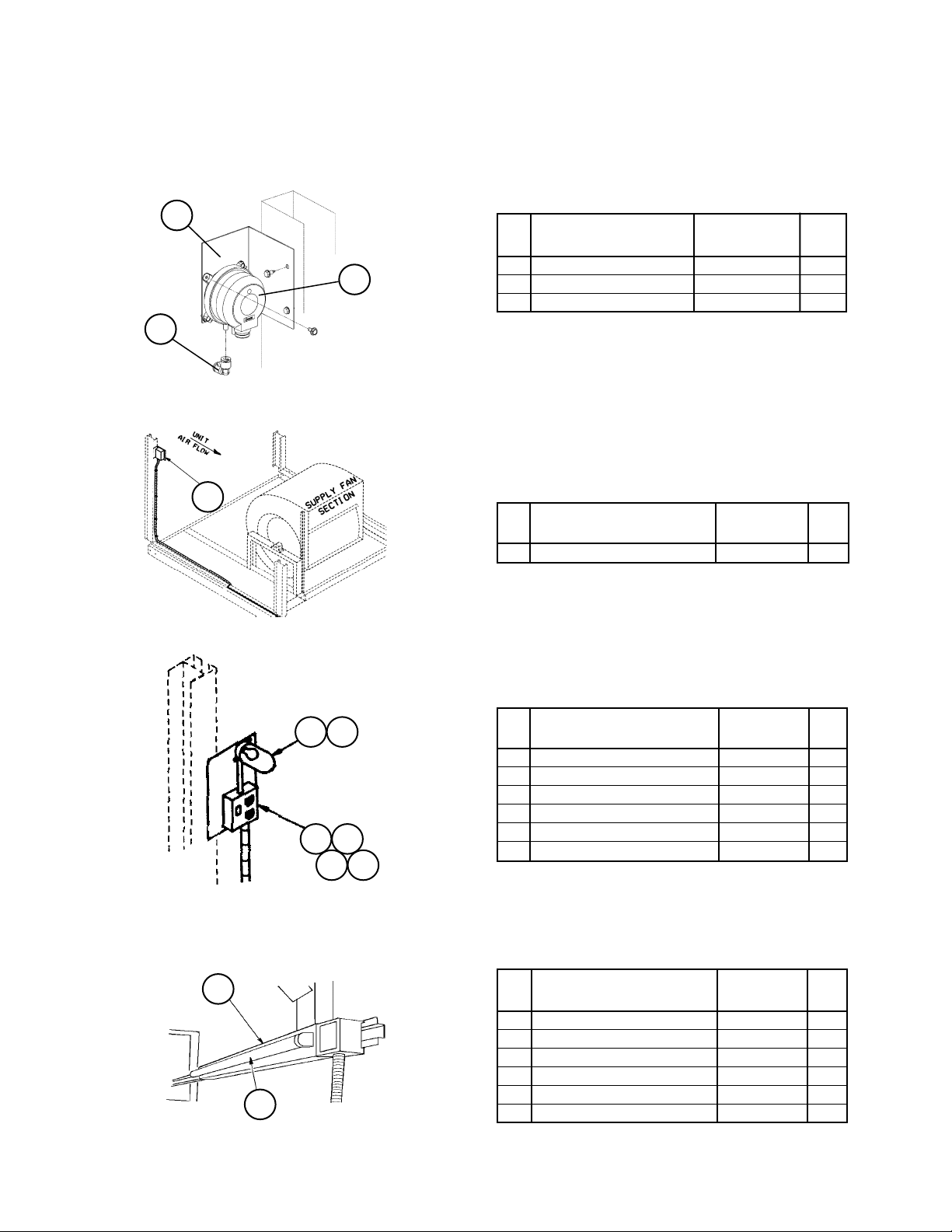
20
15
67
Section F- Supply Air Section
Section Mounted Controls
PC7, HL22, LT10, S10, REC10, UV Lights
PC7- Proof of Airflow Pressure Control
Ref Part Part
No. Description Number Qty.
19
15 Bracket
19 Pressure Control- PC7
20 Pneumatic Fitting
1
During May & June of 2012 PC7 was changed to p/n 910115489
using Pneumatic Fitting 910122414. Units built May & June of
2012 and earlier with the old PC7 Switch require Retrofit Kit
910122413 as the old and new parts are NOT interchangeable.
For units built during May & June of 2012, contact Daikin McQuay
parts to ensure that the required part(s) are ordered.
HL22- Gas Heat Hi Limit Switch
C04= A
Ref Part Part
No. Description Number Qty.
67 T-stat- HL22 Hi Limit 047938801 1
1
1
1
1
1
1
98
99
84 85
86 87
88 89
LT10- Return Fan Light/S10- Return Fan Light
Switch/ REC10- Return Fan Light Receptacle
C49= B or E
Ref Part Part
No. Description Number Qty.
84 Light Fixture 042229500 1
85 Bulb- LT10 065492402 1
86 Junction Box 065491901 1
87 Junction Box Cover 065492001 1
88 Light Switch- S10 065492201 1
89 Receptacle- REC10 030187000 1
UV Lights
Code 17= C1 thru C8, Y1 thru Y8
Ref Part Part
No. Description Number Qty.
98 Lamp Holder- 18” 205484001 1
Lamp Holder- 24” 205484101 1
Lamp Holder- 36” 205484201 1
99 Lamp- 18” 205484501 1
Lamp- 24” 205484601 1
Lamp- 36” 205484701 1
RoofPak Singlezone; RPS,RDT,RFS,RCS 045-079 “D” Rev. U 07/12 RPL 700013700 / Page 79
Page 80

Section F- Supply Air Section
Section Mounted Controls
MATS, EFTS, SATS, DATS, OATS, SD1
5
Mixed Air Temperature Sensor- MAT or
Entering Fan Temperature Sensor- EFT
Ref Part Part Qty.
No. Description Number
5 EF Temp. Sensor- EFT 193414602 1
EFTS
Supply Air Temperature Sensor- SAT or
Discharge Air Temperature Sensor- DAT
8
DATS
OATS
51
Ref Part Part Qty.
No. Description Number
8 DA Temp. Sensor- DAT 193414602 1
7
Outdoor Air Temperature Sensor- OAT
Ref Part Part Qty.
No. Description Number
7 OA Temp. Sensor- OAT 193414602 1
Smoke Detector- SD1
Smoke
Detector
Detail
RoofPak Singlezone; RPS,RDT,RFS,RCS 045-079 “D” Rev. U 07/12 RPL 700013700 / Page 80
50
Ref Part Part Qty.
No. Description Number
50 Smoke Detector- SD1 098873101 1
51 Sensing Tube 049025002 1
Page 81

Section F- Supply Air Section
Section Mounted Controls
SCB- Split Junction Box (Code 05= F)- TB25,TB27,TB28,PB10,PB9,PB20,PB19
TB28 TB27 TB25
PB 19 PB 20 PB 9 PB 10
Motor HP
2 - 25 30 40, 50
Sch. Part Part
Sym. Description Number
Terminal Blocks
TB25 Terminal Block- SCB 015998124 1 1 1 1 1 1 1 1 1 1 1 1
TB27 Terminal Block- SCB 015998130 1 1 1 1 1 1 1 1 1 1 1 1
TB281 Terminal Block- SCB 015998124 1 1 1 1 1 1 1 1 1 1 1 1
PB10 Power Block- Supply Fan
95A, 600V, 3P 030372707 1 1 1 1 1 1 1 1 1 1 1 1
PB9 Power Block- Supply Fan
95A, 600V, 3P 030372707 1
PB20 Power Block- Return Fan
95A, 600V, 3P 030372707 1 1 1 1 1 1 1 1
PB19 Power Block- Return Fan
95A, 600V, 3P 030372707 1
1
Only used when the unit has a supply fan inverter or an Economizer with a Power Closure Exhaust Damper.
208V
230V
460V
575V
208V
230V
460V
575V
208V
230V
460V
575V
RoofPak Singlezone; RPS,RDT,RFS,RCS 045-079 “D” Rev. U 07/12 RPL 700013700 / Page 81
Page 82
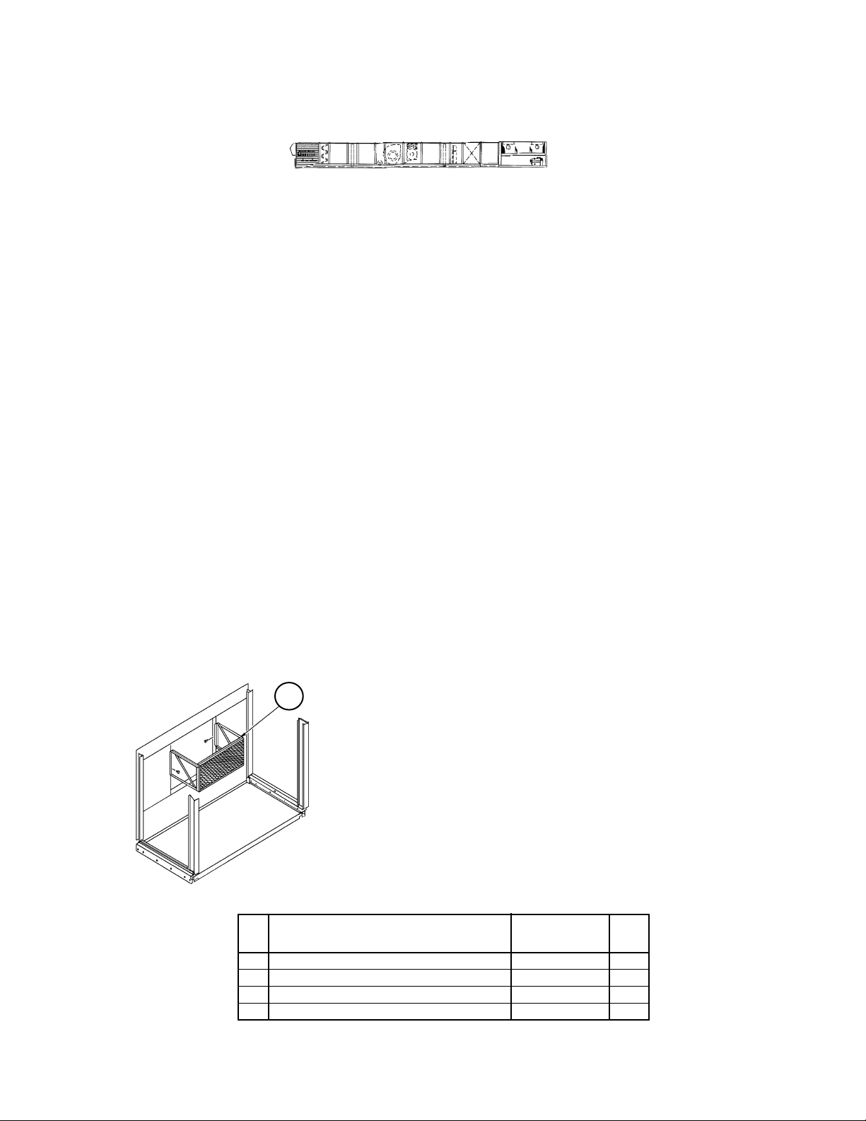
Section G- Blow-Thru Heat Section
Notes
➩
Primary Codes that pertain: 04, 34
Additional Codes that pertain: 06, 07, 08, 09, 12, 31
Code 04 determines what type of heat, if any, the unit employs, and code 34 defines the specific heat section’s
characteristics. If Code 04= Y, and Code 34= YYYYYY there is no section. If Code 04= Y and Code 34= BBBBBB,
then there is a 40” Blank Access Section installed. Otherwise, see the nomenclature page for specific heat section
definition. This section is divided into four subsections: 1. Blank Access; 2. HW/Steam Heat; 3. Electric Heat; and
4. Gas Heat.
Code 07 is the Gas Heat Burner Approval Code and affects many of the parts in the gas heat section depending on
whether the unit is UL approved (USA) or CSA approved (Canada).
Code 08 determines which generation of controls are installed which determines which electric heat controls are
used. Code 09 determines the Unit Voltage, which will have an effect on the electric heaters and their controls.
Code 12 determines the Control type and will affect the gas heat actuator motor. Code 31 is the supply fan size,
and affects the heat section’s diffusers.
Code 06 determines the insulation and liners and will affect the Top Panel, Uprights, and Door Assembly part
numbers. For sheet metal components that make up the Blow-Thru Heat Section, contact Daikin McQuay
Parts to insure correct liners, insulation and hardware are ordered.
Option 1: Blank Compartment
Code 34= BBBBBB and Code 04= Y
Diffuser
12
The drawing shows a diffuser factory mounted on a unit split at the condenser (Code 05= C),
or not split (Code 05=Y). If the unit is split at the Supply Fan (Section F) and Heat (Section G)
the diffuser is field mounted. The part number is the same in either case.
Ref Part Part
No. Description Number Qty.
12 Diffuser
27” Supply Fan C31= 27** 055988001 1
30” Supply Fan C31= 30** 055988002 1
33” Supply Fan C31= 33** 055988003 1
RoofPak Singlezone; RPS,RDT,RFS,RCS 045-079 “D” Rev. U 07/12 RPL 700013700 / Page 82
Page 83

Section G- Blow-Thru Heat Section
Option 2: Hot Water or Steam Coil Heat, Mixing Valves and Actuator (VM1)
Code 34 first 3 digits = S11, S12, S13, S14, W11, W12, W22
Diffuser
12
Ref Sch. Part Code Coil Coil Part
No. Sym. Description 34= Type Height Number Qty.
2 Steam Heat Coil- Bottom S11*** 5JA0601H 30” 056053021 1
Steam Heat Coil- Bottom S12*** 5JA1201H 30” 056053022 1
Steam Heat Coil- Bottom S13*** 5JA0602C 30” 056053023 1
Steam Heat Coil- Bottom S14*** 5JA1202C 30” 056053024 1
Hot Water Heat Coil- Bottom W11*** 5WH0901H 30” 056053025 1
Hot Water Heat Coil- Bottom W22*** 5WS0902C 30” 056053026 1
3 Steam Heat Coil- Top S11*** 5JA0601H 27” 056053031 1
Steam Heat Coil- Top S12*** 5JA1201H 27” 056053032 1
Steam Heat Coil- Top S13*** 5JA0602C 27” 056053013 1
Steam Heat Coil- Top S14*** 5JA1202C 27” 056053014 1
Hot Water Heat Coil- Top W11*** 5WH0901H 27” 056053035 1
Hot Water Heat Coil- Top W22*** 5WS0902C 27” 056053016 1
12 Diffuser- 27” Supply Fan 055988001 1
Diffuser- 30” Supply Fan 055988002 1
Diffuser- 33” Supply Fan 055988003 1
63 VM1 Actuator- 120V *****E All All 059999804 1
64 Linkage- 1.25”, 1.50” or 2.00” Valve *****E All All 049762401 1
Linkage- 2.50” or 3.00” Valve *****E All All 049762403 1
65 Valve, 2 Way— Steam Heat
1.25” S**E2* 5JA All 049762502 1
1.50” S**F2* 5JA All 049762503 1
2.00” S**G2* 5JA All 049762504 1
2.50” S**H2* 5JA All 049762505 1
3.00” 1 S**J2* 5JA All 049762506 1
Valve, 3 Way— Hot Water Heat
1.25” W**E3* 5WH, 5WS All 047936505 1
1.50” W**F3* 5WH, 5WS All 047936501 1
2.00” W**G3* 5WH, 5WS All 047936502 1
2.50” W**H3* 5WH, 5WS All 047936506 1
3.00” 2 W**J3* 5WH, 5WS All 047936503 1
1
Steam Heat 3.00” valve has a flange gasket p/n: 031315900.
2
Hot Water Heat 3.00” valve has a flange gasket p/n: 031316000.
Coil Location
3
2
Mixing Valve Detail
63
64
65
RoofPak Singlezone; RPS,RDT,RFS,RCS 045-079 “D” Rev. U 07/12 RPL 700013700 / Page 83
Page 84

Section G- Blow-Thru Heat Section
Option 3: Electric Heat— Code 34 first digit = E
Heaters, Diffusers, Hi Limit Cutouts HL1-20, 31-50
Diagram & Components
5
12
Air
Flow
7
7A
6
Hi Limit Cutout Unit
with with Voltage
Auto and Auto
Ref Sch. Part Total Code Heater Manual Cutout
No. Sym. Description KW 34= KW Cutout 1 Only
2
460V
208/230V
5 Heater Assy- Top 40 E040 40 049269208 049269217 1
Heater Assy- Top 40 E040 40 049269226 049269235 1
Heater Assy- Top 40 E040 40 N/A 049269244 1
Heater Assy- Top 60 E060 60 049269207 049269216 1
Heater Assy- Top 60 E060 60 049269225 049269234 1
Heater Assy- Top 60 E060 60 N/A 049269243 1
Heater Assy- Top 80 E080 80 049269206 049269215 1
Heater Assy- Top 80 E080 80 049269224 049269233 1
Heater Assy- Top 80 E080 80 N/A 049269242 1
Heater Assy- Top 100 E100 100 049269205 049269214 1
Heater Assy- Top 100 E100 100 049269223 049269232 1
Heater Assy- Top 100 E100 100 N/A 049269241 1
Heater Assy- Top 120 E120 120 049269204 049269213 1
Heater Assy- Top 120 E120 120 049269222 049269231 1
Heater Assy- Top 120 E120 120 N/A 049269240 1
Heater Assy- Top 160 E160 160 049269203 049269212 1
Heater Assy- Top 160 E160 160 049269221 049269230 1
Heater Assy- Top 160 E160 160 N/A 049269239 1
Heater Assy- Top 200 E200 120 049269201 049269210 1
Heater Assy- Top 200 E200 120 049269219 049269228 1
Heater Assy- Top 200 E200 120 N/A 049269237 1
Heater Assy- Top 240 E240 120 049269201 049269210 1
Heater Assy- Top 240 E240 120 049269219 049269228 1
Heater Assy- Top 240 E240 120 N/A 049269237 1
N/A= Not Applicable.
1
Units ETL/MEA approval (Code 07= EY) or no approval (Code 07= YY). Heater assy includes Hi Limit auto and manual reset switches.
2
Units CSA approval (Code 07= CY). Heater assy includes Hi Limit auto reset switches.
575V
RoofPak Singlezone; RPS,RDT,RFS,RCS 045-079 “D” Rev. U 07/12 RPL 700013700 / Page 84
Page 85
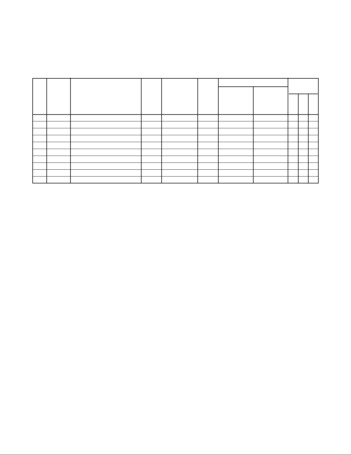
Section G- Blow-Thru Heat Section
Option 3: Electric Heat— Code 34 first digit = E
Heaters, Diffusers, Hi Limit Cutouts HL1-20, 31-50
Components, Continued
Hi Limit Cutout Unit
with with Voltage
Auto and Auto
Ref Sch. Part Total Code Heater Manual Cutout
No. Sym. Description KW 34= KW Cutout 1 Only
2
6 Blank Assy- Bottom 40- 160 E/040- 160 055923601 055923601 1 1 1
Heater Assy- Bottom 200 E200 80 049269202 049269211 1
Heater Assy- Bottom 200 E200 80 049269220 049269229 1
Heater Assy- Bottom 200 E200 80 N/A 049269238 1
Heater Assy- Bottom 240 E240 120 049269201 049269210 1
Heater Assy- Bottom 240 E240 120 049269219 049269228 1
Heater Assy- Bottom 240 E240 120 N/A 049269237 1
7 HL1-20 Hi Limit- Manual Cutout All All All 065496201 N/A var var var
7A HL31-50 Hi Limit- Auto Cutout All All All 065824501 065824201 var var var
12 Diffuser All All All 055645701 055645201 1 1 1
N/A= Not Applicable.
1
Units ETL/MEA approval (Code 07= EY) or no approval (Code 07= YY). Heater assy includes Hi Limit auto and manual reset switches.
2
Units CSA approval (Code 07= CY). Heater assy includes Hi Limit auto reset switches.
460V
208/230V
575V
RoofPak Singlezone; RPS,RDT,RFS,RCS 045-079 “D” Rev. U 07/12 RPL 700013700 / Page 85
Page 86
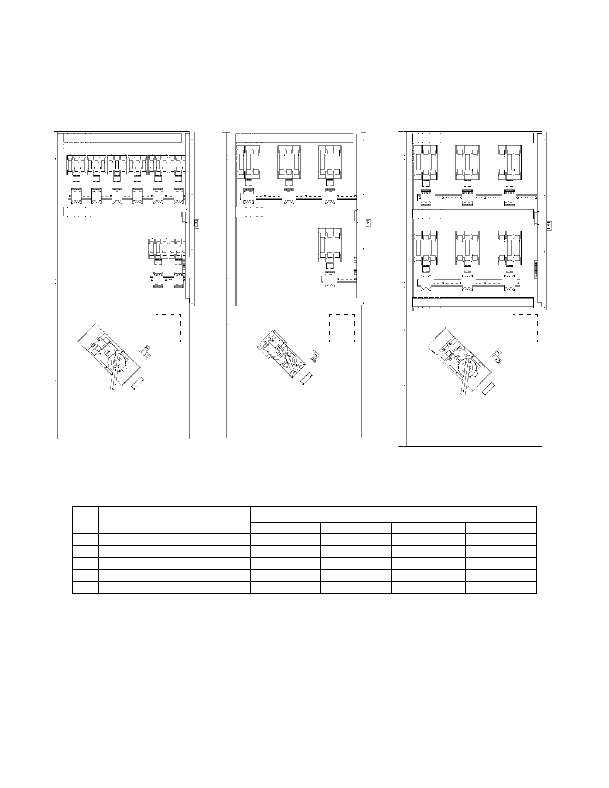
Section G- Blow-Thru Heat Section
Option 3: Electric Heat— Code 34 first digit = E
Electric Heat Control Box
Diagrams & Components
FB33 FB37
M33 M37 M32 M36 M31 M35
FB32 FB36 FB31 FB35
FB34 FB38
M34 M38
PB31 PB31 PB31
DS3
or
PB3
208/230V
20KW- 160KW
FB33 FB32
M33
H
S
3
T
B
11
DS3
or
PB3
M32 M31
FB31
FB34
M34
H
S
3
T
B
11
460/575V
20KW- 160KW
FB33 FB32
M33
DS3
or
PB3
M32 M31
FB42FB43
M42M43
460/575V
200KW- 240KW
FB31
FB41
M41
H
S
3
T
B
11
DS3- Disconnect Switch
1
Sch. Part Disconnect Switch Component
Sym. Description Amps Switch Handle 2 Shaft Ground Lug
DS3 Disconnect Switch 100 Amp 349935125 349935523 349962211 349938001
Disconnect Switch 150 Amp 349935126 349935533 349962212 349938001
Disconnect Switch 250 Amp 349935226 349935533 349962212 349938001
Disconnect Switch 400 Amp 349935325 349935622 349962213 349938002
Disconnect Switch 600 Amp 193438206 3
1
Disconnects are sized according to various unit specifications. Check installed switch to verify the correct DS3 size.
2
Includes mechanism (except 600A switch, see footnote 4).
3
The original “M” frame disconnect is obsolete and replaced with a “P” frame switch. Due to dimensional differences minor field
modifications may be required for proper installation.
4
Handle only p/n 349961102; Mechanism only p/n 193455001; Shaft p/n 349961403.
RoofPak Singlezone; RPS,RDT,RFS,RCS 045-079 “D” Rev. U 07/12 RPL 700013700 / Page 86
4
349962243 349938002
Page 87

Section G- Blow-Thru Heat Section
Option 3: Electric Heat— Code 34 first digit = E
Electric Heat Control Box
20- 120KW Components, Continued
Heater KW=
20 40 60 80 100 120
Sch. Part Part
208V
230V
460V
575V
230V
460V
575V
230V
460V
575V
230V
460V
575V
230V
460V
575V
230V
Sym. Description Number
208V
208V
208V
208V
PB3 Power Block 030372777 1 1 1 1 1 1 1 1 1 1 1 1 1 1 1 1
Power Block 030372785 1 1 1 1 1 1 1 1
PB31 Power Block 4
used w/100A, 150A DS3 030372777 1 1 1 1 1 1 1 1 1 1 1 1 1 1 1 1 1 1 1 1 1 1 1 1
used w/250A DS3 030372783 1 1 1 1 1 1 1 1 1 1 1 1 1 1 1 1 1 1 1 1 1 1 1 1
used w/400A DS3 030372785 1 1 1 1 1 1 1 1 1 1 1 1 1 1 1 1 1 1 1 1 1 1 1 1
5
used w/600A DS3 030372721
1 1 1 1 1 1 1 1 1 1 1 1 1 1 1 1 1 1 1 1 1 1 1 1
208V
460V
575V
DS3 Disconnect Switch
2
HS3 Switch 033696300 1 1 1 1 1 1 1 1 1 1 1 1 1 1 1 1 1 1 1 1 1 1 1 1
TB11 Terminal Block 349930641
1 1 1 1 1 1 1 1 1 1 1 1 1 1 1 1 1 1 1 1 1 1 1 1
M31 Contactor 349932321 1 1 1 1 1 1
Contactor 349932322 1 1 1 1 1 1 1 1 1 1 1 1 1 1 1 1 1 1
M32 Contactor 349932322 1 1 1 1 1 1 1 1 1 1 1 1 1 1
Contactor 349932321 1 1 1 1 1 1
M33 Contactor 349932322 1 1 1 1 1 1 1 1
Contactor 349932321 1 1 1 1 1 1
M34 Contactor 349932322 1 1 1 1 1 1 1 1
Contactor 349932321 1 1 1 1 1 1
M35 Contactor 349932322 1 1 1 1
M36 Contactor 349932322 1 1
1
Part number is for one section. The number of sections used is determined by the options installed.
2
See charts on previous page.
4
Not used when PB3 power block connection is present.
5
Cover- PB31 for 600A DS3= p/n 349938345.
RoofPak Singlezone; RPS,RDT,RFS,RCS 045-079 “D” Rev. U 07/12 RPL 700013700 / Page 87
Page 88

Section G- Blow-Thru Heat Section
Option 3: Electric Heat— Code 34 first digit = E
Electric Heat Control Box
20- 120KW Components, Continued
Heater KW=
20 40 60 80 100 120
Sch. Part Part
208V
230V
460V
575V
230V
460V
575V
230V
460V
575V
230V
460V
575V
230V
460V
575V
230V
Sym. Description Number
208V
208V
208V
208V
208V
460V
FB31 Fuse Block 023780229 1 1 1 1 1 1 1 1 1 1 1 1
Fuse Block 023780225 1 1 1 1 1 1
Fuse Block 023780230 1 1 1 1 1 1
FB32 Fuse Block 023780229 1 1 1 1 1 1 1 1 1 1
Fuse Block 023780225 1 1 1 1 1 1
Fuse Block 023780230 1 1 1 1
FB33 Fuse Block 023780229 1 1 1 1 1 1 1 1
Fuse Block 023780225 1 1 1 1 1 1
FB34 Fuse Block 023780229 1 1 1 1 1 1 1 1
Fuse Block 023780225 1 1 1 1 1 1
FB35 Fuse Block 023780229 1 1 1 1
FB36 Fuse Block 023780229 1 1
F31 Fuse- FB31 025860514 3 3 3 3 3 3 3 3 3 3
Fuse- FB31 025860511 3
Fuse- FB31 025860512 3
Fuse- FB31 025860409 3 3 3
Fuse- FB31 025860408 3 3 3
Fuse- FB31 025860412 3
Fuse- FB31 025860411 3
Fuse- FB31 025860414 3 3
Fuse- FB31 025860413 3 3
F32 Fuse- FB32 025860514 3 3 3 3 3 3 3 3
Fuse- FB32 025860511 3
Fuse- FB32 025860512 3
Fuse- FB32 025860409 3 3 3
Fuse- FB32 025860408 3 3 3
Fuse- FB32 025860412 3
Fuse- FB32 025860411 3
Fuse- FB32 025860414 3
Fuse- FB32 025860413 3
F33 Fuse- FB33 025860511 3
Fuse- FB33 025860512 3
Fuse- FB33 025860514 3 3 3 3 3 3
Fuse- FB33 025860409 3 3 3
Fuse- FB33 025860408 3 3 3
F34 Fuse- FB34 025860511 3
Fuse- FB34 025860512 3
Fuse- FB34 025860514 3 3 3 3 3 3
Fuse- FB34 025860409 3 3 3
Fuse- FB34 025860408 3 3 3
F35 Fuse- FB35 025860514 3 3 3 3
F36 Fuse- FB36 025860514 3 3
575V
RoofPak Singlezone; RPS,RDT,RFS,RCS 045-079 “D” Rev. U 07/12 RPL 700013700 / Page 88
Page 89
Section G- Blow-Thru Heat Section
Option 3: Electric Heat— Code 34 first digit = E
Electric Heat Control Box
160- 240KW Components
Heater KW=
160 200 240
Sch. Part Part
208V
230V
460V
575V
Sym. Description Number
PB3 Power Block
Power Block
PB31 Power Block
4
030372785 1 1 1 1
030372786 1 1 1 1
460V
575V
460V
used w/100A/150A DS3 030372777 1 1 1 1 1 1 1 1
used w/250A DS3 030372783 1 1 1 1 1 1 1 1
used w/400A DS3 030372785 1 1 1 1 1 1 1 1
used w/600A DS3 030372721 5 1 1 1 1 1 1 1 1
DS3 Disconnect Switch
2
HS3 Switch 033696300 1 1 1 1 1 1 1 1
TB11 Terminal Block 349930641 1 1 1 1 1 1 1
M31 Contactor 349932322 1 1 1 1 1 1 1 1
M32 Contactor 349932322 1 1 1 1 1 1 1 1
M33 Contactor 349932322 1 1 1 1 1 1 1 1
M34 Contactor 349932322 1 1 1 1
M35 Contactor 349932322 1 1
M36 Contactor 349932322 1 1
M37 Contactor 349932322 1 1
M38 Contactor 349932322 1 1
M41 Contactor 349932322 1 1 1 1
M42 Contactor 349932322 1 1 1 1
M43 Contactor 349932322 1 1
1
Part number is for one section. The number of sections used is determined by the options
installed.
2
See chart 3 pages prior.
4
Not used when PB3 power block connection is present.
5
Cover- PB31 for 600A DS3= p/n 349938345.
575V
1
RoofPak Singlezone; RPS,RDT,RFS,RCS 045-079 “D” Rev. U 07/12 RPL 700013700 / Page 89
Page 90

Section G- Blow-Thru Heat Section
Option 3: Electric Heat— Code 34 first digit = E
Electric Heat Control Box
160- 240KW Components
Heater KW=
160 200 240
Sch. Part Part
208V
230V
460V
575V
Sym. Description Number
460V
575V
460V
FB31 Fuse Block 023780229 1 1
Fuse Block 023780230 1 1 1 1 1 1
FB32 Fuse Block 023780229 1 1
Fuse Block 023780225
Fuse Block 023780230 1 1 1 1 1 1
FB33 Fuse Block 023780229 1 1
Fuse Block 023780230 1 1 1 1 1 1
FB34 Fuse Block 023780229 1 1
Fuse Block 023780230 1 1
FB35 Fuse Block 023780229 1 1
FB36 Fuse Block 023780229 1 1
FB37 Fuse Block 023780229 1 1
FB38 Fuse Block 023780229 1 1
FB41 Fuse Block 023780230 1 1 1 1
FB42 Fuse Block 023780230 1 1 1 1
FB43 Fuse Block 023780230 1 1
F31 Fuse- FB31 025860514 3 3
Fuse- FB31 025860414 3 3 3
Fuse- FB31 025860413 3 3 3
F32 Fuse- FB32 025860514 3 3
Fuse- FB32 025860414 3 3 3
Fuse- FB32 025860413 3 3 3
F33 Fuse- FB33 025860514 3 3
Fuse- FB33 025860414 3 3 3
Fuse- FB33 025860413 3 3 3
F34 Fuse- FB34 025860514 3 3
Fuse- FB34 025860414 3
Fuse- FB34 025860413 3
F35 Fuse- FB35 025860514 3 3
F36 Fuse- FB36 025860514 3 3
F37 Fuse- FB37 025860514 3 3
F38 Fuse- FB38 025860514 3 3
F41 Fuse- FB41 025860414 3 3
Fuse- FB41 025860413 3 3
F42 Fuse- FB42 025860414 3 3
Fuse- FB42 025860413 3 3
F43 Fuse- FB43 025860414 3
Fuse- FB43 025860413 3
575V
RoofPak Singlezone; RPS,RDT,RFS,RCS 045-079 “D” Rev. U 07/12 RPL 700013700 / Page 90
Page 91

Section G- Blow-Thru Heat Section
Option 4- Gas Heat Code 04= A
Vestibules, Heat Exchangers and Primary Components
200 or 250 MBH Furnaces
Code 34= 020** or 025**
Burner
Burner
Control
4
Box
Gas Train
22
21
Heat
Exchanger
3
5
1
38
Ref Part 200/250 Qty.
No. Description MBH
1 Heat Exchanger- Stainless Steel Secondary C34= ***S** 098320652 1
21 Vestibule 055636308 1
22 Vestibule 055636303 1
38 Capillary Plate 059360301 1
N/A= Not Applicable.
3
Parts detail follows this section.
4
Parts detail follows Burner section.
5
Parts detail follows Burner Control Box section.
RoofPak Singlezone; RPS,RDT,RFS,RCS 045-079 “D” Rev. U 07/12 RPL 700013700 / Page 91
Page 92

Section G- Blow-Thru Heat Section
Option 4- Gas Heat Code 04= A
Vestibules, Heat Exchangers and Primary Components
320, 400, 500, 640, 650, 790, 800, 1000
Code 34= 032**, 040**, 050**, 064**, 065**, 079**, 080**, 100**
Heat
Exchanger
21
22
1
Burner
3
Burner
Control
4
Box
Gas Train
Ref Part 320/400 500/640 650/790 800/1000 Qty.
No. Description MBH MBH MBH MBH
1 Heat Exchanger 098320654 098320656 098320658 098320660 1
21 Vestibule 055636309 055636309 055636309 055636309 1
22 Vestibule 055636304 055636305 055636306 055636307 1
N/A= Not Applicable.
3
Parts detail follows this section.
4
Parts detail follows Burner section.
5
Parts detail follows Burner Control Box section.
5
RoofPak Singlezone; RPS,RDT,RFS,RCS 045-079 “D” Rev. U 07/12 RPL 700013700 / Page 92
Page 93
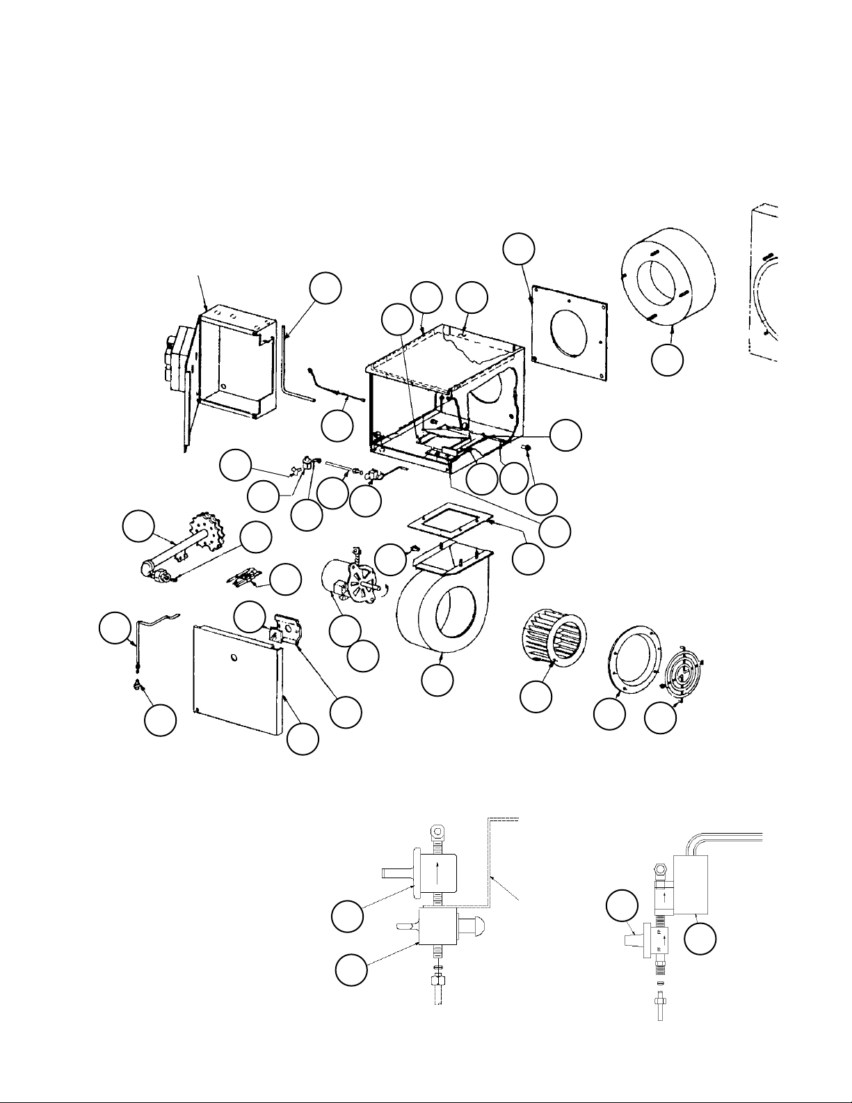
Section G- Blow-Thru Heat Section
Option 4- Gas Heat: Code 04= A
Modulating Burner:
Code 34= ****E*, ****R*, ****S*
Diagrams
126
Burner Control
Box
106
142
122
120
143
111
144
125
130
119
105
110
115
123
149102
114
113
109
147
112
124
116
117
145
103
104
127
121
118
200, 250, 320
MBH Burners
107
108
400- 1000 MBH
Burners
Pilot Valve/ Pressure
Regulator Assy Detail
160
161
RoofPak Singlezone; RPS,RDT,RFS,RCS 045-079 “D” Rev. U 07/12 RPL 700013700 / Page 93
Burner
Control
Box
160
162
Page 94

Section G- Blow-Thru Heat Section
Option 4- Gas Heat: Code 04= A
Modulating Burner:
Code 34= ****E*, ****R*, ****S*
Components
Ref Part C07=EU, EF, EI C07= CC, CD
No. Description UL/ETL CSA
102 Burner Housing 059362302 059362302 1
103 Scroll 035740701 035740701 1
104 Wheel- .5” bore, CCW 034861102 034861102 1
105 Motor- .25 HP, 115/60/1 034249200 034249200 1
106 Gun Assembly:
200 MBH Furnace 034879901 034879901 1
250 MBH Furnace 034879902 034879902 1
320 MBH Furnace 034879903 034879903 1
400 MBH Furnace 034879904 034879904 1
500 MBH Furnace 034880001 034880001 1
640 MBH Furnace 034880002 034880002 1
650 MBH Furnace 034880002 034880002 1
790 MBH Furnace 034880003 034880003 1
800 MBH Furnace 034880003 034880003 1
1000 MBH Furnace 034880004 034880004 1
107 Inlet Funnel 034743101 034743101 1
108 Fan Guard 034742800 034742800 1
109 Blast Tube:
200 - 400 MBH Furnace 037378802 037378802 1
500 - 650 MBH Furnace 034101703 034101703 1
790 - 1000 MBH Furnace 034101707 034101707 1
110 Pilot Mixer 036516401 036516401 1
111 Pilot Assembly 035019600 035019600 1
112 Damper Assembly 035721501 048791401 1
113 Blast Tube Gasket 034102000 034102000 1
114 Right Side Damper:
200 - 500 MBH Furnace 058594301 058594301 1
640 MBH Furnace 058595201 058595201 1
650 - 1000 MBH Furnace 058594501 058594501 1
115 Left Side Damper:
200 - 640 MBH Furnace 058595001 058595001 1
650 - 1000 MBH Furnace 058594401 058594401 1
Burner Approval Code
Qty.
RoofPak Singlezone; RPS,RDT,RFS,RCS 045-079 “D” Rev. U 07/12 RPL 700013700 / Page 94
Page 95
Section G- Blow-Thru Heat Section
Option 4- Gas Heat: Code 04= A
Modulating Burner:
Code 34= ****E*, ****R*, ****S*
Components, Continued
Burner Approval Code Qty.
Ref Part C07=EU, EF, EI C07= CC, CD
No. Description UL/ETL CSA
116 Slide Damper:
200 MBH Furnace 058594801 058594811 1
250 MBH Furnace 058594802 058594812 1
320 MBH Furnace 058594803 058594813 1
400 MBH Furnace 058594804 058594814 1
500 MBH Furnace 058594805 058594815 1
640 MBH Furnace 058594806 058594816 1
650 MBH Furnace 058594807 058594817 1
790 MBH Furnace 058594808 058594818 1
800 MBH Furnace 058594809 058594819 1
1000 MBH Furnace 058594810 058594820 1
117 Blower Gasket 035019500 035019500 1
118 Burner Cover 033972100 033972100 1
119 Ignition Assembly 034742900 034742900 1
120 Glass Cover 036557000 036557000 1
121 Glass Cover Support 036009600 036009600 1
122 Orifice:
200 MBH Furnace 058599301 058599301 1
250 MBH Furnace 058599302 058599302 1
320 MBH Furnace 058599303 058599303 1
400 MBH Furnace 059861501 059861501 1
500 MBH Furnace 058599101 058599101 1
640 MBH Furnace 058599102 058599102 1
650 MBH Furnace 058599103 058599103 1
790 MBH Furnace 058599104 058599104 1
800 MBH Furnace 058599104 058599104 1
1000 MBH Furnace 058599201 058599201 1
123 Clip 034919400 034919400 1
124 Flange Bearing 034252000 034252000 2
125 Air Switch Tube 034102801 034102801 1
126 Pilot Burner Tube:
200 - 400 MBH Furnace 036236000 036236000 1
500 - 1000 MBH Furnace 036236100 036236100 1
127 Compression Fitting 034097500 034097500 1
130 Pilot Tube 034102601 034102601 1
142 Manual Cock Valve- 200-320 MBH only not used 034077300 1
143 Press. Reg. Valve- 200-320 MBH only not used 034077600 1
144 90º Comp. Elbow- 200-320 MBH only not used 034097200 1
145 Motor Conduit Box- 200-320 MBH only 036558800 036558800 1
147 Torsion Spring not used 037528600 1
149 Burner Box Baffle:
200 - 400 MBH Furnace 058597901 058597901 1
500 - 1000 MBH Furnace 058597902 058597902 1
160 Valve- Pressure Regulator 034077600 034077600 1
161 Valve- Manual: 200-320 MBH 034077300 034077300 1
162 Valve- Solenoid: 400- 1000 MBH 034488400 034488400 1
RoofPak Singlezone; RPS,RDT,RFS,RCS 045-079 “D” Rev. U 07/12 RPL 700013700 / Page 95
Page 96

Section G- Blow-Thru Heat Section
Option 4- Gas Heat: Code 04= A
Hi Turn Down Burner:
Code 34= ****H*, ****T*, ****U*
Diagrams
118
120
121
106
110
105
119
358
328
358
114
102
109
113
116
295
300
310
318
500 - 1000 MBH
322
375
324
297
110
324
200 - 400 MBH
325
145
117
321
323
320
103
144
299
104
Detail: Orifice, Control Rod, Control
107
Arm, Linkage, Plate Detail
108
RoofPak Singlezone; RPS,RDT,RFS,RCS 045-079 “D” Rev. U 07/12 RPL 700013700 / Page 96
Page 97

Section G- Blow-Thru Heat Section
Option 4- Gas Heat: Code 04= A
Hi Turn Down Burner
Code 34= ****H*, ****T*, ****U*
Components
Burner Approval Code Qty.
Ref Part C07=EU, EF, EI C07= CC, CD
No. Description UL/ETL CSA
102 Burner Housing 059862103 059862103 1
103 Scroll
200 thru 800 MBH Furnace 096434806 096434806 1
1000 MBH Furnace 059862136 059862136 1
104 Wheel- .5” bore, CCW
200 thru 800 MBH Furnace 034861102 034861102 1
1000 MBH Furnace 034249005 034249005 1
105 Motor- .25 HP, 115/60/1
200 thru 800 MBH Furnace 034249200 034249200 1
1000 MBH Furnace 032248600 032248600 1
106 Gun Assembly:
200 MBH Furnace 096414801 NA 1
250 MBH Furnace 096414802 NA 1
320 MBH Furnace 096414803 NA 1
400 MBH Furnace 096414804 096414804 1
500 MBH Furnace 096414805 096414805 1
640 MBH Furnace 096414806 096414806 1
650 MBH Furnace 096414806 096414806 1
790 MBH Furnace 096414808 096414808 1
800 MBH Furnace 096414808 096414808 1
1000 MBH Furnace 096414810 096414810 1
107 Inlet Funnel
200 thru 800 MBH Furnace 034743101 034743101 1
1000 MBH Furnace 034743102 034743102 1
108 Fan Guard 034742800 034742800 1
109 Blast Tube:
200 - 400 MBH Furnace 037378802 037378802 1
500 MBH Furnace 034101703 034101703 1
640 MBH Furnace 034101703 034101707 1
650 - 1000 MBH Furnace 034101707 034101707 1
RoofPak Singlezone; RPS,RDT,RFS,RCS 045-079 “D” Rev. U 07/12 RPL 700013700 / Page 97
Page 98

Section G- Blow-Thru Heat Section
Option 4- Gas Heat: Code 04= A
Hi Turn Down Burner
Code 34= ****H*, ****T*, ****U*
Components, Continued
Burner Approval Code Qty.
Ref Part C07=EU, EF, EI C07= CC, CD
No. Description UL/ETL CSA
110 Orifice Assembly
200 MBH Furnace 096414701 NA 1
250 MBH Furnace 096414702 NA 1
320 MBH Furnace 096414703 NA 1
400 MBH Furnace 096414704 096414724 1
500 MBH Furnace 096414705 096414725 1
640 MBH Furnace 096414706 096414726 1
650 MBH Furnace 096414707 096414727 1
790 & 800 MBH Furnace 096414708 096414728 1
1000 MBH Furnace 096414710 096414730 1
113 Gasket- Blast Tube 034102000 034102000 1
114 Air Box Assy 059862112 059862112 1
116 Plate- Actuator Scale 059645001 059645001 1
117 Gasket- Blower 035019500 035019500 1
118 Panel- Burner Box Cover 059388501 059388501 1
119 Ignition Wire Assy 034742902 034742902 1
120 Glass Cover- Burner 036557000 036557000 1
121 Support- Glass Cover 036009600 036009600 1
144 Grommet- Flat 060017701 060017701 1
145 Box- Conduit 036558800 036558800 1
295 Motor- Actuator 111047701 111047701 1
297 Control Arm 059862114 059862114 1
299 Control Rod 059861101 059861101 1
300 Crank Arm 059645101 059645101 1
310 Extension- Crank Arm 059862110 059862110 1
318 Bushing- Control Rod 059861301 059861301 1
320 Linkage 096414901 096414901 1
321 Plate- Adjustable
200 MBH Furnace 096422001 NA 1
250 MBH Furnace 096421601 NA 1
320 MBH Furnace 059389601 NA 1
400 MBH Furnace 096423001 096423101 1
500 MBH Furnace 060086401 096422901 1
640 MBH Furnace 096417701 096417801 1
650 MBH Furnace 096416301 096416301 1
790 MBH Furnace 060097101 060097101 1
800 MBH Furnace 060097101 096422701 1
1000 MBH Furnace 060092401 060097301 1
RoofPak Singlezone; RPS,RDT,RFS,RCS 045-079 “D” Rev. U 07/12 RPL 700013700 / Page 98
Page 99

Section G- Blow-Thru Heat Section
Option 4- Gas Heat: Code 04= A
Hi Turn Down Burner
Code 34= ****H*, ****T*, ****U*
Components, Continued
Ref Part C07=EU, EF, EI C07= CC, CD
No. Description UL/ETL CSA
322 Plate- Profile
200 & 250 MBH Furnaces 096421501 NA 1
320 MBH Furnace 059389001 NA 1
400 MBH Furnace 060097601 060097601 1
500 MBH Furnace 060086101 060086101 1
640 MBH Furnace 096417901 096417901 1
650 MBH Furnace 096415301 096418001 1
790 MBH Furnace 096416501 096416501 1
800 MBH Furnace 060096901 060097001 1
1000 MBH 060092601 060097201 1
323 Plate- Slide Damper
200, 250, 320, 400 MBH Furnaces 059388801 059388801 1
500 MBH Furnace 060086301 060086301 1
640, 650 MBH Furnaces 096417601 096417601 1
790, 800, 1000 MBH Furnaces 060092501 060092501 1
324 Box- Air
200 thru 400 MBH Furnaces 059869101 059869101 1
500 thru 1000 MBH Furnaces 060092201 060092201 1
325 Gasket- Air Box 060092301 060092301 1
328 Grommet 000498100 000498100 1
358 Bearing- Sleeve 046761000 046761000 2
375 Grommet- 500 thru 1000 MBH only 059988700 059988700 1
Burner Approval Code
Qty.
RoofPak Singlezone; RPS,RDT,RFS,RCS 045-079 “D” Rev. U 07/12 RPL 700013700 / Page 99
Page 100

Section G- Blow-Thru Heat Section
Option 4- Gas Heat: Code 04= A
Modulating Burner Controls:
Code 34= ****E*, ****R*, ****S*
No Controls (C12= YM, YC)
Diagram
25
26
27
FSG Detail
25
22
63
29
24
61
39
31
34
41
30
32
Gas
Control
Box
11
RoofPak Singlezone; RPS,RDT,RFS,RCS 045-079 “D” Rev. U 07/12 RPL 700013700 / Page 100
 Loading...