

Page 1

Installation and Maintenance Manual IM 787
Field Installed SpeedTrol™ for
RoofPak™ Singlezone Rooftop Units
RPS/RDT/RCS 036C-135C
Group: Aftermarket Products
Part Number: 300040599
Date: December 2003
© 2003 McQuay International
Page 2

Table of Contents
Typical Component Locations . . . . . . . . . . . . . . . . . . . . . . . . . . . . . . . . . . . . . . . . . . . . . . . . . . . . . . . . . . . . . . . . . . . . . . . . . 3
Figure 1 Typical Component Locations . . . . . . . . . . . . . . . . . . . . . . . . . . . . . . . . . . . . . . . . . . . . . . . . . . . . . . . . . . . . . . . 3
Condenser Fan Arrangement . . . . . . . . . . . . . . . . . . . . . . . . . . . . . . . . . . . . . . . . . . . . . . . . . . . . . . . . . . . . . . . . . . . . . . . . . . . 4
Figure 2 Condenser Fan Arrangement . . . . . . . . . . . . . . . . . . . . . . . . . . . . . . . . . . . . . . . . . . . . . . . . . . . . . . . . . . . . . . . 4
Field Installation of SpeedTrol Option to “C” Vintage Rooftop Units: RPS/RDT/RCS (Sizes 036-135) . . . . . . . . . . . . . . . 5
Figure 3 Typical Schematic for RPS/RDT Units . . . . . . . . . . . . . . . . . . . . . . . . . . . . . . . . . . . . . . . . . . . . . . . . . . . . . . . . 6
Figure 4 Typical Schematic for RCS Units . . . . . . . . . . . . . . . . . . . . . . . . . . . . . . . . . . . . . . . . . . . . . . . . . . . . . . . . . . . . 7
Figure 5 Remove Panel V04 . . . . . . . . . . . . . . . . . . . . . . . . . . . . . . . . . . . . . . . . . . . . . . . . . . . . . . . . . . . . . . . . . . . . . . . 8
Figure 6 SpeedTrol Panels . . . . . . . . . . . . . . . . . . . . . . . . . . . . . . . . . . . . . . . . . . . . . . . . . . . . . . . . . . . . . . . . . . . . . . . . 9
Figure 7 Typical Condenser Box Control Panel . . . . . . . . . . . . . . . . . . . . . . . . . . . . . . . . . . . . . . . . . . . . . . . . . . . . . . . 10
Figure 8 Typical Condenser Box Power Panel . . . . . . . . . . . . . . . . . . . . . . . . . . . . . . . . . . . . . . . . . . . . . . . . . . . . . . . . 11
WARNING
Moisture in control panel can cause severe personal injury and damage equipment.
When servicing this equipment during rainy weather, protect electrical components in main control panel from
rain.
™ ® The following are trademarks or registered trademarks of McQuay International: FanTrol, MicroTech, MicroTech II,
RoofPak and SpeedTrol.
2 IM 787
Page 3
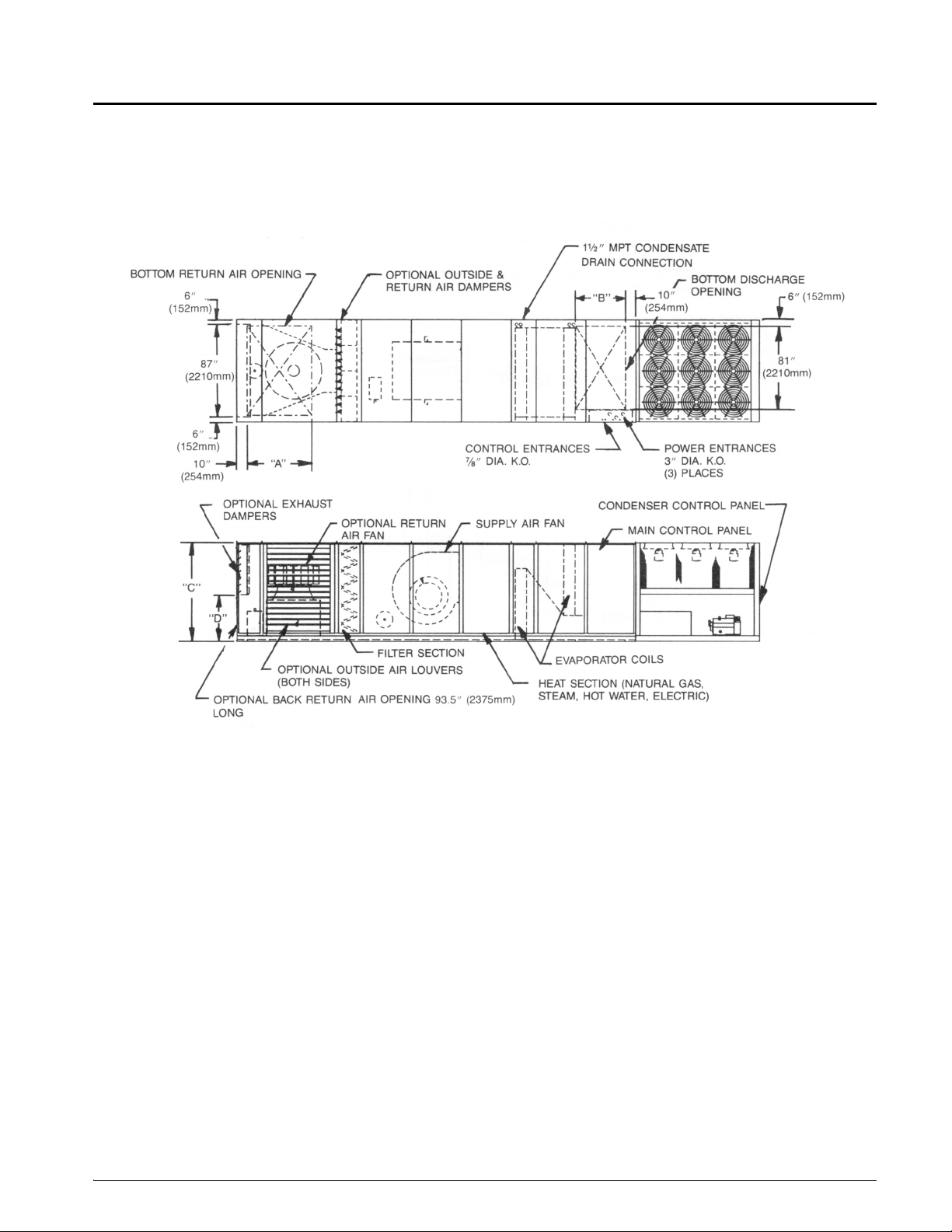
Typical Component Locations
Figure 1 shows a typical RPS unit with the location of the
major components and also lists some major dimensions.
These figures are for reference only.
Figure 1: Typical Component Locations
IM 787 3
Page 4

Condenser Fan Arrangement
Figure 2 shows the condenser fan numbering conventions and locations for each unit size with SpeedTrol application.
Figure 2: Condenser Fan Arrangement
Unit Size Refrig.Circuit Arrangement
12
11
036C
040C
May be a
Singular or
Dual Circuit Unit
22
21
100" (2540 mm)
12
1
2
100" (2540 mm)
11
22
21
83”
COND. AHU
045C
1
11 12
050C
060C
2
1
2
21 22
11 12
23
21 22
83”
13
Low Ambient (SpeedTrol)
Fan No.
11
21
11
21
11
21
11
21
070C
075C
080C
090C
105C
115C
125C
135C
1
2
1
2
1
2
1
2
1
2
11
21
11
24
21
11
24
21
11
25
21
11
251526
21
12
22
12
22
12
25
22
12
22 23
12
22 23
119”
13
23
119”
13
14
23
119”
13
14
23
139”
13 14
139”
13 14
16
11
21
11
21
11
21
11
15
24
21
11
21
24
4 IM 787
Page 5

Field Installation of SpeedTrol Option to “C” Vintage
Rooftop Units: RPS/RDT/RCS (Sizes 036-135)
McQuay's SpeedTrol system of head pressure control operates in conjunction with FanTrol™ by modulating the motor
speed of the last condenser fan of each refrigeration circuit
in response to condenser pressure. By varying the speed of
the last condenser fan of each refrigeration circuit, the
SpeedTrol option allows mechanical cooling operation in
ambient temperatures down to 0°F (-18°C). SpeedTrol controllers SC11 and SC21 sense refrigerant head pressure and
vary the fan speed accordingly. When the pressure rises,
SpeedTrol increases the fan speed; when the pressure falls,
SpeedTrol decreases the fan speed. The SpeedTrol controller's throttling range is 140 to 200 psig (965-1379 kPa) fixed.
The SpeedTrol fan motor is a single phase, 208/240 volt,
thermally protected motor specially designed for variable
speed application. Units with 460-volt power have a transformer mounted inside the condenser fan compartment to
step the voltage down to 230 volts for the SpeedTrol motor.
A portion of a typical SpeedTrol power circuit schematic is
shown in Figure 3 on page 6 and Figure 4 on page 7.
1. Before proceeding, confirm all electrical power has
been terminated to the entire unit.
2. Using Figure 2 on page 4, (Condenser fan arrangements) identify the correct fan arrangement according to
the unit size being worked on and locate condenser fans
11 and 21.
3. Make note of the fan blade position in relation to the fan
deck panel so the fan blade is installed in the exact same
position during reassembly on the motor shaft to assure
maximum efficiency.
4. Remove condenser motor assemblies 11 and 21. Do not
discard the motor mount or mounting hardware, and
make sure not to damage the existing motor wire harness. These items will be needed during reassembly.
Note: The three phase motors and fan blades that were
removed will no longer be needed.
WARNING
Electric shock hazard. Before proceeding, lock and tag out all power sources to unit.
IM 787 5
Page 6

5. Install the new single phase motor, motor slinger (6-3/4"
diameter plastic disc), and fan blade into fan positions
11 and 21 using the existing motor mount and hardware
Figure 3: Typical Schematic for RPS/RDT Units
mentioned in step 4. Position fan blade in the same
location that was noted in step 3.
6. Reconnect motor wire harness to motor as shown on
schematics in Figures 3 or 4.
6 IM 787
Page 7

Figure 4: Typical Schematic for RCS Units
IM 787 7
Page 8

7. Remove panel V04 . Locate and add a rectangular cutout per dimensions shown on tabulated chart per unit
Figure 5: Remove Panel V04
size. Set panel V04 aside for the time being and keep
panel mounting screws for later.
CABINET
SIZE
PANEL SIZE
(REF. ONLY)
A x B
CUTOUT SIZE
C x D
RPS 125 SHOWN
FAN QTY. WILL VARY PER UNIT SIZE
SEE FIGURE 2 FOR APPROPRIATE
FAN LAYOUT
E
F
A
D
E
C
B
F
V04
CONDENSER END PANEL
CONDENSER BOX
CONTROL DOOR
V04
CONDENSER BOX
POWER DOOR
V14 SPEEDTROL COVER
#10 DRILL SCREW
8 IM 787
Page 9

8. With the condenser end panel V04 removed, the condenser bulkhead will be accessible to mount (2) SpeedTrol panels. See Figure 6 to aid in positioning SpeedTrol
panel for circuit 1 and circuit 2.
9. Locate the wire harness for condenser motors 11 and 21
in the condenser power box and disconnect the wire harnesses from their respective contactors M11 and M21.
Reroute both motor wire harnesses to the SpeedTrol
panels for circuit 1 and 2 as shown in Figure 6. Condenser motor 11 to be assigned circuit 1 and motor 21 to
be assigned circuit 2. Trim the motor harness wires to
the appropriate length and crimp the 1/4 quick connects
in place. Wire SpeedTrol panels as shown in Figures 3
or 4.
Figure 6: SpeedTrol Panels
NOTE:
1. ATTACH SPEEDTROL CAPILLARIES TO SCHRAEDER FITTINGS
ON DISCHARGE TUBING AS SHOWN BELOW.
2. UNITS WITH VOLTAGES 380/460/415/575V HAVE A TRANSFORMER
T11, 208/230 DO NOT.
SEE NOTE #1
SEE NOTE #1
FROM
MTR. #11
FROM
MTR. #21
SEE NOTE #2
TO CONDENSER
CONTROL BOX
SPEEDTROL PANEL #1
(CIRCUIT #1)
TO CONDENSER
CONTROL BOX
SPEEDTROL PANEL #2
(CIRCUIT #2)
IM 787 9
Page 10

10. Mounting condenser control and power electrical components:
• Figure 7 (Condenser Box Control Panel) shows locations of the time delay relays TD11 & TD12 and relays
R11 & R12. These components are required for units
with MicroTech™ controls and units with no controls.
RCS rooftop units require an additional transformer
(T10), mount this transformer in upper left of control
panel as shown. Refer to original condenser box control
schematic for wiring instructions.
Figure 7: Typical Condenser Box Control Panel
• Figure 8 (Condenser Box Power Panel) on page 11
shows the mounting location of fuse block FB11. Refer
to Figure 3 or 4 for rewiring of existing fuse blocks, as
well as fuse block FB11.
• If the rooftop unit being worked on has MicroTech II™
controls, the software configuration string position 5
must be set to value 1 or (YES) as shown in Table 1 on
page 11. Changing this requires an AAHU MicroTech
II service tools.
CIRCUIT 1
RELAY
CIRCUIT 1
TIME DELAY
CIRCUIT 2
TIME DELAY
CIRCUIT 2
RELAY
10 IM 787
Page 11

Figure 8: Typical Condenser Box Power Panel
NOTE:
QUANTITIES OF FUSE BLOCKS AND
CONTACTORS WILL VARY PER UNIT SIZE.
NOTE DIRECTION OF
L1 - L3 ON THIS DRAWING.
FOR ALL COMPONENTS.
.
MOUNTING LOCATION
OF FUSEBLOCK FB11
Table 1: Software Configuration String
Configuration
String Position
Description
5 Low Ambient
Values
(Default in bold)
0 FanTrol
1 SpeedTrol
11. Replace condenser end panel V04 using existing mounting screws and place SpeedTrol cover V14 over the
opening created in V04 in step 7.
12. Add SpeedTrol Access label on SpeedTrol cover V14.
13. Please place this Instruction Manual in the Condenser
Control Box.
14. Return electrical power to unit.
IM 787 11
Page 12

This document contains the most current product information as of this printing. For the most up-to-date
product information, please go to www.mcquay.com.
www.mcquay.com • 800-432-1342
 Loading...