

Page 1

Replacement Parts List No. 057117700
Revision AM 07/12
Roofpak
Applied Rooftop Units
RPS/RFS/RCS
Sizes: 015 - 040
Vintage: C
To find your Daikin McQuay Parts distributor, call 1-800-377-2787 or visit www.DaikinMcQuay.com
Page 2

Contents
Parts List Revision History ............................................................................................................................................5, 6
Nomenclature ............................................................................................................................................................... 7- 15
Electrical Legend ....................................................................................................................................................... 16- 20
Section A1- Outdoor/Return Air Section
Notes .........................................................................................................................................................................21
100% Outside Air Damper with Hood- C20= AE or AY and C19= YY No Return Air Plenum ...................................22
Damper Detail ............................................................................................................................................................23
0- 30% Outside Air Section- C20= BE or BY and C19= BY or HY Damper Detail .....................................................24
0- 100% Economizer Section with Barometric Exhaust Damper- Units without Return Air Fans ..............................25
0- 100% Economizer Section with Exhaust Damper- Units with 15" Forward Curved Return Air Fans .....................26
0- 100% Economizer Section with Exhaust Damper- Units with 30" Air Foil Return Air Fans ...................................27
0- 100% Economizer Section with Exhaust Damper- Units with 40" Air Foil Return Air Fans ...................................28
0- 100% Economizer Assembly ...........................................................................................................................29, 30
Return Air Plenum Isolation Damper w/ Actuator ACT6 .............................................................................................31
Design Flow Detail .....................................................................................................................................................32
Return Air Fan Mounting- 15" Forward Curved Fan ...................................................................................................33
Return Air Fan Mounting- 30" and 40" Airfoil Fan- Until 12/04 (original fan design) ..................................................34
Return Air Fan Mounting- 30" and 40" Airfoil Fan- 12/04 and later (current fan design) ............................................35
Return Air Fan Deck- 15" Fans: C21= 15F1, 15F2 or 15F3 .......................................................................................36
Return Air Fan Deck- 30" Fans: C21= 30W or 30B- Until 12/04 ................................................................................37
Return Air Fan Deck- 30" Fans: C21= 30B1, 30B2 OR 30B3- 12/04 & Later ............................................................38
Return Air Fan Deck- 40" Fans: C21= 40W or 40B- Until 12/04 ................................................................................39
Return Air Fan Deck- 40" Fans: C21= 40B1, 40B2 OR 40B3- 12/04 & Later ............................................................40
Return Air Fan Motors ................................................................................................................................................41
Section Mounted Controls- OAE, RAE, LT11, S11, REC11 .......................................................................................42
Section A2- Outdoor/Return/Heat Recovery Air Section
Notes .........................................................................................................................................................................43
100% Outside Air Low Flow - C20= 1E ......................................................................................................................44
100% Outside Air High Flow- C20= 2E ......................................................................................................................45
Economizer - C20= 3E ...............................................................................................................................................46
24" Return Fan Detail .................................................................................................................................................47
24" Return Fan Detail- Fan Motors, Motor Mount ......................................................................................................48
24" Return Fan Detail- Fan Mounts ............................................................................................................................49
Low Leak Damper Detail- MicroTech II Units .............................................................................................................50
Low Leak Damper Detail- MicroTech III Units ............................................................................................................51
Low Leak Bypass Damper Detail- MicroTech II Units) ...............................................................................................52
Low Leak Bypass Damper Detail- MicroTech III Units) ..............................................................................................53
Heat Recovery— Enthalpy— Wheel Detail ................................................................................................................54
AFD60 Frost Protection Inverter (Code 24= F) ..........................................................................................................54
Section Mounted Controls- OAE, RAE, RAT, EAT, LAT ............................................................................................55
Section Mounted Controls- SD2, HUM1, LT11, S11, REC11 ....................................................................................56
Section B- Draw-Thru Filter/Blank Section
Notes .........................................................................................................................................................................57
Section Mounted Controls- PC5, SPS5 ......................................................................................................................57
Filter Section Assembly ..............................................................................................................................................58
Section C- Draw-Thru Blank Access Section or Separate Inverter Section
Notes .........................................................................................................................................................................59
Section D- Draw-Thru Cooling Section
Notes .........................................................................................................................................................................60
Evaporator Coil, Gasket and Drain Pans ...................................................................................................................61
Evaporator Coils Unit Sizes 036 & 040 Only ..............................................................................................................62
Section E- Draw-Thru Blank Access Section
Notes .........................................................................................................................................................................63
Section Mounted Controls- LT17, REC17, S17 ..........................................................................................................63
Section F- Supply Air Section
Notes .........................................................................................................................................................................64
Draw-Thru Evaporator Coil Drain Pans: Unit Sizes 015 thru 030 ..............................................................................65
Rooftop Units: RPS/RFS/RCS 015- 040 "C" Rev. AM 07/12 RPL 057117700 / Page 2
Page 3

Contents, Continued
Section F- Supply Air Section- Continued
Evaporator Coils- Unit Sizes 015 thru 030 Only .........................................................................................................66
Fan Assembly- 15" X 6" and 15" X 15" Forward Curved Fans ..................................................................................67
Fan Assembly- 20" Airfoil Fans w/o Variable Inlet Vanes ..........................................................................................68
Fan Assembly- 20" Airfoil Fans with Variable Inlet Vanes..........................................................................................69
Fan Assembly- 24" Forward Curved LP Fans ...........................................................................................................70
Fan Assembly- 24" Forward Curved MP Fans ..........................................................................................................71
Fan Assembly- 24" Airfoil Fans w/o Variable Inlet Vanes ..........................................................................................72
Fan Assembly- 24" Airfoil Fans with Variable Inlet Vanes..........................................................................................73
Supply Air Fan Mounting- 15" x 6" or 15" X 15" Forward Curved Fan .......................................................................74
Supply Air Fan Mounting- 20" Airfoil Fan- Until 12/04 (original fan design) ...............................................................75
Supply Air Fan Mounting- 20" Airfoil Fan- 12/04 and later (current fan design) .........................................................76
Supply Air Fan Mounting- 24" Airfoil Fan- Until 12/04 (original fan design) ...............................................................77
Supply Air Fan Mounting- 24" Airfoil Fan- 12/04 and later (current fan design) .........................................................78
Supply Air Fan Mounting- 24" Forward Curved Fan- Until 12/04 (original fan design)...............................................79
Supply Air Fan Mounting- 24" Forward Curved Fan- 12/04 and later (current fan design) ........................................80
Supply Fan Motors .....................................................................................................................................................81
Inverters & Inverter Bypass Control Box- Until 3/05 ...................................................................................................82
Inverters & Inverter Bypass Control Box- 3/05 to 10/06
Motor HP 1-5 ...................................................................................................................................................83, 84
Motor HP 7.5- 25 ............................................................................................................................................ 85- 87
Inverters & Inverter Bypass Control Box- 1/07 & Later
Motor HP 1-5 ...................................................................................................................................................88, 89
Motor HP 7.5 - 25 (Code 22 or Code 32= K, L, M, N or P) ............................................................................ 90- 92
Inverters .............................................................................................................................................................. 93- 95
Section Mounted Controls- PC7, MAT, EFT, HL22, LT10, S10, REC10, UV Lights ..................................................96
Section G- Blow-Thru Heat Section
Notes .........................................................................................................................................................................97
Option 1: Blank Compartment
Diffusers ................................................................................................................................................................97
Option 2: Hot Water or Steam Heating Coil
Coil and Coil Compartment Components ..............................................................................................................98
Valve ......................................................................................................................................................................99
Option 3: Electric Heat
Diffusers, High Limit HL4, HL14 & HL 31- 50 ..............................................................................................100, 101
Electric Heat Control Box- Until 3/05 ...........................................................................................................102, 103
Electric Heat Control Box- 3/05 & Later- MicroTech II Units or No Controls .............................................. 104- 107
Electric Heat Control Box- 9/08 & Later- MicroTech III Units ..................................................................... 108- 110
Option 4- Gas Heat Code 04= A
Vestibules, Heat Exchangers and Primary Components- 200 or 250 MBH Furnaces .......................................111
Vestibules, Heat Exchangers and Primary Components- 320, 400, 500, 640, 650, 790, 800, 1000 ..................112
Modulating or Single Stage Burner ............................................................................................................. 113- 115
Hi Turn Down Burner .................................................................................................................................. 116- 119
Single Stage or Modulating Burner Controls
MicroTech Controls (Code 12= 1M, 2M, 3M, 4M, 5M or YM) ..........................................................................120
MicroTech II Controls (C12= LD, LS, BD, BS, ED, ES, SD, SS) or No Controls (C12= YM, YC) Diagram .....121
MicroTech II or No Controls Components. .......................................................................................................122
MicroTech III Controls (C12= LE, LF, BE, BF, EE, EF, SE, SF) ......................................................................123
Hi Turn Down Burner Controls
MicroTech II Controls (C12= LD, LS, BD, BS, ED, ES, SD, SS) or No Controls (C12= YM, YC) Diagram .....124
MicroTech II or No Controls Components. .......................................................................................................125
MicroTech III Controls (C12= _E or _F) ...........................................................................................................126
Gas Train- Inlet ............................................................................................................................................127, 128
Gas Train- Controls .....................................................................................................................................129, 130
Gas Train- Outlet .................................................................................................................................................131
Gas Train- Damper Linkage ........................................................................................................................132, 133
Cabinet Doors, Gasketing, Hardware, and Flue Box Mounting .................................................................. 134- 136
Section H- Blow-Thru Heat Blank Access Section
Notes .......................................................................................................................................................................137
Rooftop Units: RPS/RFS/RCS 015- 040 "C" Rev. AM 07/12 RPL 057117700 / Page 3
Page 4

Contents, Continued
Section I- Blow-Thru Cooling Section
Notes .......................................................................................................................................................................138
Drain Pans ................................................................................................................................................................139
Evaporator Coils .......................................................................................................................................................140
Section J- Final Filter Section
Notes .......................................................................................................................................................................141
Section Mounted Controls- HL23, PC6,SPS6 ..........................................................................................................141
Filter Frame, Filter Gaskets, Filters ..........................................................................................................................142
Section K- Discharge Plenum Section
Notes .......................................................................................................................................................................143
Section Mounted Controls- OAT, DAT, SAT, SD1 ...................................................................................................143
Damper Assembly- w/ Actuator ACT5 ......................................................................................................................144
Section L- Out-of-Airstream Blank Access Section
Notes .......................................................................................................................................................................145
Section M- Condenser Section
Notes .......................................................................................................................................................................146
Section Mounted Controls- PC22, PC12 ..................................................................................................................146
RPS/RCS 018C, 020C, 025C, 030C- Units with Semi Hermetic Compressors ...............................................147, 148
RPS/RCS 015C, 018C, 020C, 025C, 030C- Units with Scroll Compressors .................................................. 149- 153
RPS/RCS 036C, 040C- Units with Semi Hermetic Compressors ....................................................................154, 155
RPS/RCS 036C, 040C- Units with Scroll Compressors .................................................................................. 156- 160
Compressor Mounting ..............................................................................................................................................161
Condenser Control Box- RPS/RCS 018C, 020C, 025C, 030C
MicroTech Controls until 1/01
RPS/RCS Units with Semi- Hermetic Compressors ............................................................................... 162- 163
MicroTech Controls Until 3/05- RPS/RCS 015C, 018C, 020C, 025C, 030C
RPS/RCS Units with Scroll Compressors ............................................................................................... 164- 168
MicroTech II Controls 3/05 & Later*
RCS Units with Scroll Compressors ....................................................................................................... 169- 172
MicroTech III Controls- 9/08 & Later
RCS 015C, 018C, 020C, 025C, 030C .....................................................................................................173, 174
Condenser Control Box- RPS/RCS 036C & 040C
MicroTech Controls until 1/01
RPS/RCS Units with Semi- Hermetic Compressors ................................................................................175, 176
MicroTech Controls Until 3/05- RPS/RCS 036C, 040C
RPS/RCS Units with Scroll Compressors ............................................................................................... 177- 180
MicroTech II Controls 3/05 & Later
RCS 036C, 040C .................................................................................................................................... 181- 185
MicroTech III Controls 9/08 & Later
RCS 036C, 040C .....................................................................................................................................186, 187
Speedtrol Control Box and Transformer ...................................................................................................................188
F7 Fuse Box- RPS 036C, 040C ...............................................................................................................................188
Control Box- McQuay Supplied Line Voltage Box- T6, DS6, FU6A, FU6B, FU6C ...................................................189
Section N- Main Control Box
Notes .......................................................................................................................................................................190
Control Panel- Units with MicroTech Controls- (C12= 1M, 2M, 4M, 5M)— Until 1/01......................................191, 192
Control Panel- Units with MicroTech II Controls— 1/01 until 3/05 .................................................................. 193- 195
Control Panel- Units without MicroTech Controls ............................................................................................196, 197
Power Panel- Until 3/05 ................................................................................................................................... 198- 210
Control Panel 3/05 and later- MicroTech II Units or Units with No Controller ................................................ 211- 216
Control Panel 9/08 and later- MicroTech III Units with Controller ................................................................... 217- 219
Power Panel 3/05 to 10/06 .............................................................................................................................. 220- 240
Power Panel 1/07 & later ................................................................................................................................. 241- 260
Refrigeration Tubing
Notes .......................................................................................................................................................................261
RPS, RCS- Units with Semi-Hermetic Discus Compressors ....................................................................................262
RPS, RCS- Units with Scroll Compressors ..............................................................................................................263
Rooftop Units: RPS/RFS/RCS 015- 040 "C" Rev. AM 07/12 RPL 057117700 / Page 4
Page 5

Parts List Revision History
Rev. Date Description
1st Draft 4/98 Draft Copy
2nd Draft 6/98 2nd Draft Copy - Corrected Compressor part numbers on page 164.
3rd Draft 10/98 3rd Draft Copy-Corrected Compressor part numbers for sizes 036-040 on page 164.
New 1/99 Status change from Draft Copy to New.
Page 120 Removed Ref. #685 from drawing.
Page 150 Corrected part numbers for Horizontal Copper Fin Coils (Ref.# 5).
A 2/99 Page 114 Added Codes H, T and U to descriptions.
B 4/99 Page 20 Corrected part numbers for Economizer Dampers (Ref.# 11) and Exhaust Louvers (Ref.# 12) on Back
Return and Bottom Return units.
C 8/00 Page 178 Added Ref. #. #314 & Ref. #. #379 to diagram.
Page 180 Added Ref. #. #379 description.
D 11/00 Page 77 Ref. #. 25- Bearing P.B. Qty changed from 1 to 2.
Page 167 Added Fuses and Fuse Blocks, (Ref. # 410 & 411).
Page 169 Added Fuses and Fuse Blocks, (Ref. # 410 & 411).
Page 171 Added Fuses and Fuse Blocks, (Ref. # 410 & 411).
Page 173 Added Fuses and Fuse Blocks, (Ref. # 410 & 411).
E 2/01 Page 164 3 part no.'s were incorrect for Compressor sizes 030-035, 2-step,C42=2; 208AL/PW, 230 AL/PW &
380 AL p/n's all were 049267300 and have been changed to 049267200.
F 6/02 Page 177 Added Earthquake Bracket Kit #067794901 and Hurricane Bracket Kit #066320940.
G 6/06 Reformatted entire book. Added Inverters, Hi Turn Down Burners, MicroTech II Controls, new Design Fans, UV
Lights, Design Flow, Scroll Compressors, new Condenser Control Box, new nomenclature, Electrical Legend.
H 07/06 Page 73 Added EFT diagram & table.
Page 153 Sensor had schematic designation of ENT corrected to EFT.
Page 173 Sensor had schematic designation of ENT corrected to EFT.
J 09/06 'Heat Recovery' data' added as follows;
Pages 7,8,13-17,113,151-153,156,158-169,171-175,179 - Replaced page. New page added after page 193
of Rev. H. Eleven new pages added after page 39 of Rev. H. Heading changed on pages 18-39 of Rev. H-
changed "Section A" to Section A1.
K 01/07 Page 77 Replaced page 77 (Inverter information).
Page 79 & 82 - Short Circuit Alarm p/n changed from 349933003 to 349933903.
Page 85 New page added. Document repaginated.
L 01/07 Page 52 Code 25 paragraph was revised.
Page 91 Added note to Heater Cross Ref. tables about Ref. Letter U.
M 01/07 Page 102 Replaced High Turndown Burner drawing with 'sharpened up' version.
Page 109 Ref. #.205 -p/n was changed from 034077301 to 034077300.
N 02/07 Pages 113 &115 were replaced with new pages because of artwork changes & additional columns and footnotes.
O 12/08 Extensive reformatting, added 35 additional pages including power panel and control panel components "1/07
later", new FSG, new McQuay Inverters, 5% impedance inverters, PC12 & 22 fantrol diagrams, quiet
condenser fans & associated components, TEAO condenser fan motors & associated components, new R22 &
R407c (7/08 & later) compressors and associated components, 120V unit powered receptacle panel.
P 1/09 Page 9 Code 15- added MicroTech III to selection "F".
Page 12 Codes 12, 17, 18- added MicroTech III. Code 13- added selection "8".
Page 14 Added ACT4 and EXPA, B, D to legend.
Page 16 Added SPS3 to legend.
Page 17 Added R63 & R81- 88 to legend.
Page 18 Added TD20 to legend.
Page 19 Added MicroTech III to notes.
Page 40 RAT- added p/n for MicroTech III and original MicroTech controls.
Page 42 Ref. #12- added p/n 110905009 for MicroTech III.
Page 43 Ref. #12- added p/n 110905009 for MicroTech III.
Page 44 Ref. #12- added p/n 110905009 for MicroTech III. Ref. #230-added p/n 110919907 for MicroTech III.
Page 48 Added MicroTech II to subheading.
Page 49 Added new for MicroTech III controls low leak damper. Document repaginated.
Page 50 Added MicroTech II to subheading.
Page 51 Added new for MicroTech III controls low leak bypass damper. Document repaginated.
Page 53 RAT, EAT, LAT- added sensor p/n for MicroTech III controls.
Page 54 Added footnote for wall mounted humidistat.
Page 55 SPS5- added footnote for MicroTech III controls.
Page 102 Amended date range and added "MicroTech II" and "No Controls" to subheading.
Page 103 Amended date range and added "MicroTech II" and "No Controls" to subheading.
M31- "1/07 & later" p/n 349932322 & 349932323 rows switched.
M41- 60KW 208/230V p/n changed to 349932321.
Page 104 Amended date range and added "MicroTech II" and "No Controls" to subheading.
F31 & F41- 60KW 208/230V p/n changed to 025860514.
F33 & F43- quantity changed to "3".
Page 105 Amended date range and added "MicroTech II" and "No Controls" to subheading.
Pages 106- 108 Added new for MicroTech III units damper. Document repaginated.
Page 119 Added date range and "MicroTech II" to subheading. Ref. #32 added p/n 193423703 for units built 9/08
& later.
Page 120 Added new for Modulating Burner control box for MicroTech III. Document regaginated.
Page 121 Added "MicroTech I" & "MicroTech II" to subheading. Ref. #32 added p/n 193423703 for units built
9/08 & later.
Page 122 Added new for High Turn Down control box for MicroTech III.
Page 137 SPS6- added MicroTech III to footnote.
Page 139 OAT & DAT- added p/n for MicroTech III controls.
Page 142 Ref. #12- added MicroTech III to footnote.
Rev. P- Continued on next page.
Rooftop Units: RPS/RFS/RCS 015- 040 "C" Rev. AM 07/12 RPL 057117700 / Page 5
Page 6

Parts List Revision History, Continued
Rev. Date Description
P 1/09 Page 148 Ref. #1E- added MicroTech III to table and footnote.
(Cont.) Page 155 Ref. #1E- added MicroTech III to table and footnote.
Pages 169 & 170 Added new for unit sizes 015- 030 condenser control box for MicroTech III controls. Document
repaginated.
Page 179 Added TB1-8 for "1/07 & later".
Pages 182 & 183 Added new for unit sizes 036, 040 condenser control box for MicroTech III controls. Document
repaginated.
Pages 213- 215 Added new for MicroTech III controls main control box.
Page 237 Added MMP61 to drawing.
Page 256 Ref. #7- added M61 for HI Flow ERC units (C20= 2).
Ref. #8- added MMP61 for HI Flow ERC units (C20= 2).
Ref. #8B- changed quantity to 2 for HI Flow ERC units (C20= 2).
Q 5/09 Page 40 Ref #7 change RAT sensor p/n from 193414600 to 193414601.
Page 53 Ref # 200 change RAT sensor MTIII Controls p/n from 193414600 to 193414601.
Ref # 500 change EAT sensor MTIII Controls p/n from 193414600 to 193414601.
Ref # 600 change LAT sensor MTIII Controls p/n from 193414600 to 193414601.
Page 94 Ref # 36 change EFT sensor p/n from 193414600 to 193414601.
Page 139 Ref # 8 change OAT sensor p/n from 193414600 to 193414601.
Ref # 7 change DAT sensor p/n from 193414600 to 193414601.
Page 215 Change DAT, EFT, OAT, RAT, EAT, LAT sensor p/ns from 193414600 to 193414601.
Page 252 Ref #7 change contactor p/n from 349934221 to 349934201.
Page 253 Ref #7 change contactor p/n from 349934221 to 349934201.
R 6/09 Page 8 Move General Option codes and diagram to page 9.
Page 9-14 Arrange Code Index into numerical order. (Added two pages)
S 8/09 Page 217- Add Remote Interface p/n 193408001.
T 10/09 Page 146- Changed part number 049296800 to 046496800.
U 10/09 Page 112- Change Heat Exchanger heading from 650 MBH to 640 MBH.
V 12/09 Page 54- Changed Ref # 163, Bearing from 2pc. to 1pc. Deleted invalid p/n 300043253 for "Inner Seal". Changed
"Outer Seal" description to "Outer/Inner Seal" and changed quantity from 1pc. to 4pc.
Page 222- Added 100A DS1 parts to table. SW= 349935101, lugs- 349935901, handle- 349935501 & gnd lug-
349938001.
W 3/10 Page 74- Changed the description of Spring isolator Ref #99C p/n 022611200 from "Black" to "Blue".
Y 5/10 Page 2- 4 Corrected various TOC mismatches with document page headers.
Page 21, 43, & 64 Clarified note regarding drive information. Removed comment regarding Rapid CD and added
note to use online Drive Cross Reference form instead.
Page 114, 117 Removed Complete Burner Assembly p/ns.
Page 121, 123 (old), 121, 122, 124, 125 (New) Split diagram and table into two pages due to lack of additional
room for update of Gas Heat relays R20- R23B. Repaginated document and updated TOC.
Page 172, 187, 245 Replaced obsolete 600A disconnect switch p/n 349935332 w/ 193438002, handle
p/n 349935631 w/ 193437901, and shaft p/n 349962303 w/ 349962241. Added footnote #3.
Page 183 Changed invalid GFR4 P/N 034937502 to 349937502.
Page 262 For Sol. Valve- Hot Gas Bypass p/n: 047931304 changed use date from Until 1/01 to 1/01 & Later.
Z 6/10 Page 122 Changed p/n 026217000 to 061019403.
AA 6/28 Page 96 Added MAT information and updated Electrical Legend and TOC.
Page 34, 75, 77, 79 Corrected Code 21 description for Seismic Restraint parts to match listed fan size.
Page 143 Added SAT information and updated Electrical Legend and TOC. Deleted Ref #50 Until 2/03 p/n
060016501 and added Ref #51 Sensing Tube p/n 049025005. Deleted SD1 original footnote #1 and added new
footnotes #1 , #2,and #3 for Sensing/Sampling Tubes.
Page 194, 213 Changed MT battery p/n RB2325 to 049754501.
AB 7/10 Page 32- Deleted Ref #110 p/n 098662800 and added footnote: "P/N is unit specific. Contact McQuay Parts
with overall length and bolt hole spacing so that the correct part can be identified."
AC 10/10 Page 51- Replaced Ref #122 ACT 3 actuator p/n 1131395601 with 113139501. Added footnote #2.
Page 218- Replaced COM p/ns: 193408101 with 090016709; 193408201 with 090016711; 193408202 with
090016712, & 193408301 with 090016710.
AD 01/11 Various: Corrected misc. spelling and formatting issues.
Page 47- Added p/n & quantity for: 10A 010288108, 10B 020648652, 10C 010255211 & 10D 010298937.
Changed description for 10D to: Vane Assy w/ Inlet Funnel. Deleted footnote number 2.
Page 218- P/ns for LonWorks DAC & LonWorks SCC were reversed. DAC= 090016712, SCC= 090016711.
AE 02/11 Page 218- Changed Terminal block p/ns: 193410402 to 193410302, 193410403 to 193410303, 193410405
to 193410305, 193410406 to 193410306, 193410407 to 193410307 & 193410408 to 193410308.
AF 06/11 Page 192- Changed MCB1 p/n from 065487311 to 065487306.
AG 12/11 Page 218- Changed SPS1-3 p/ns 049545012 to 910124529 & 049545013 to 910124528. Added footnote #2.
AH 03/12 Cover, Pg. 6: Updated to current Daikin McQuay logo format.
Page 125: Added p/ns for R23A relay 349934764 & adapter 349964702. Changed R20B, R21 & R23B p/n from
193454702 to 193454703. Deleted Ref #34 MicroTech relay p/n 019643000. Changed Ref # 25 FSG from
073300801 to 073300803 and updated description. Added footnote #1.
AJ 04/12 Page 153- Added Speedtrol motor 034914500 to Ref # 35. Updated Ref #35 descriptions.
AK 06/12 Various- Changed "McQuay Parts" to "Daikin McQuay Parts".
Page 93- Added footnotes #1 & 2.
Page 94- VTAC9 Inverter p/n 098861454 is 5HP ONLY. Deleted invalid information.
Page 146- Rewrote notes.
AL 07/12 Page 62, 66, 140: Deleted Evap. Coil p/ns. Added footnote to contact PID.
AM 07/12 Page 96: Changed PC7 from 060015801 to Switch 910115489 & retrofit kit 910122413. Changed Fitting p/n from
049763002 to 910122414. Added tootnote #1 & updated drawing.
McQuay International, 13600 Industrial Park Blvd., P.O. Box 1551, Minneapolis, MN 55440 (763) 553-5330
Rooftop Units: RPS/RFS/RCS 015- 040 "C" Rev. AM 07/12 RPL 057117700 / Page 6
Page 7

Plant Identification Abbreviation
FBO = Faribault, MN
U= Unit
Year of Manufacture
99= 1999, 00= 2000, 01= 2001,
02= 2002, 03= 2003, 04= 2004,
05= 2005, 06= 2006, 07= 2007
etc.
Nomenclature
Serial Number- until 2/1999
3 7A 12345 01
Serial Number
Year and Month of Manufacture:
Factory
3= Faribault,MN
Serial Number- 2/1999 & Later
FBO U 05 10 048
Year Month
6= 1996 A= Jan. G= Jul.
7= 1997 B= Feb. H= Aug.
8= 1998 C= Mar. J= Sep.
9= 1999 D= Apr. K= Oct.
E= May L= Nov.
F= Jun. M= Dec.
Engineering Revision
Month of Manufacture
01= Jan.
02= Feb.
03= Mar.
04= Apr.
05= May
06= Jun.
07= July
08= Aug.
09= Sept.
Serial Number
(Build sequence)
10= Oct.
11= Nov.
12= Dec.
Unit Model Number
R P S 018 C S
Heating Medium
A= Natural Gas
E= Electric
S= Steam
W= Hot Water
Y= None (cooling only)
Design Vintage
Nominal Capacity (Tons)
ex. 018= 18 Tons
Singlezone Unit
Unit Configuration
P= Heating, mechanical cooling
F= Heating, future mechanical cooling
C= Condensing section only
Roofpak:
R= Roofpak Applied Rooftop
Rooftop Units: RPS/RFS/RCS 015- 040 "C" Rev. AM 07/12 RPL 057117700 / Page 7
Page 8
Nomenclature
Continued
Unit Model Number- Complete
RPS 018C S W Y 1 EY P 27 AL P1 SS 1 1 2 1 H R120 BY AE 15F2 EAY
Code 04 05 06 07 08 09 10 11 12 13 14 15 16 17 18 19 20 21 22
1250C Y AB T CYYS 4EZ103H YYYYYY BBBBBB 06F2 LKP 1250C W11D3E
23 24 25 26 27 28 29 30 31 32 33 34
CYYS 4EZ126H YYYYYY B B BY Y 4 AG K 2 1 1 Y A YYAAY
35 36 37 38 39 40 41 42 43 44 45 46 47 48 49 50-54
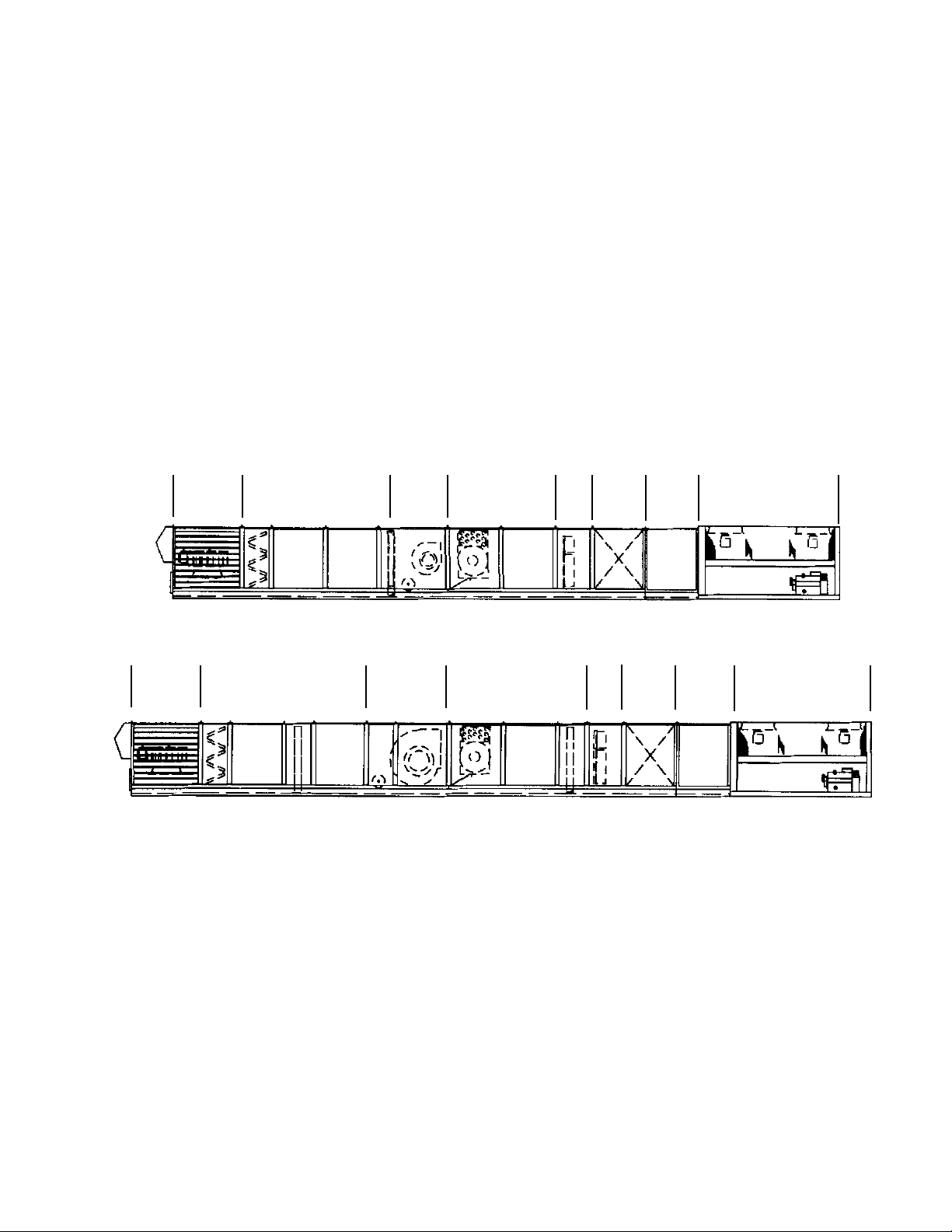
Unit Section Layout
RPS 015- 030C
A
Return/Outside
Air Section
RPS 036- 040C
A
Return/Outside
Air Section
B C E F G
B C E F G
Draw-Thru Section Supply Fan
Section
D
Draw-Thru Section Supply Fan
Section
H
Blow-Thru Section Final
Blow-Thru Section Final
J
Filter
H J
I
K
Discharge
Plenum
Filter
Blank Ac-
K
Discharge
Plenum
L
cess
L
Blank Ac-
cess
M
Condenser Section
M
Condenser Section
Rooftop Units: RPS/RFS/RCS 015- 040 "C" Rev. AM 07/12 RPL 057117700 / Page 8
Page 9
Nomenclature
Continued
General Options
Unit Model Codes that Pertain: 05, 06, 07, 51- 54
Section A
Return/Outside Air/Heat Recovery Options
Unit Model Codes that Pertain:
14, 15, 19, 20, 21, 22, 23, 24, 49
Sections B, C, D, E
Draw-Thru Cooling Sections
Section B- Filter
Unit Model Codes that Pertain: 25
Section C- Draw-Thru Blank Access
Unit Model Codes that Pertain: 26
Section D- Draw-Thru Cooling Section
Unit Model Codes that Pertain: 27, 28
Section E- Draw-Thru Blank Access
Unit Model Codes that Pertain: 30
Section F- Supply Fan Options
Unit Model Codes that Pertain:
14, 15, 31, 32, 33, 49
Sections G, H, I
Blow-Thru Options
Section G= Blow-Thru Heat/Blank
Unit Model Codes that Pertain: 04, 34
Section H= Blow-Thru Blank Access
Unit Model Codes that Pertain: 38
Section I- Blow-Thru Cooling Sections
Unit Model Codes that Pertain: 35, 36
Section J- Final Filter Section
Unit Model Codes that Pertain: 39
Section K- Discharge Plenum Section
Unit Model Codes that Pertain: 40
Section L- Blank Compartment Section- Out of
Airstream
Unit Model Codes that Pertain: 41
Section M- Condenser Section
Unit Model Codes that Pertain: 42, 43, 44, 45, 47
Section N- Main Control Panel
Unit Model Codes that Pertain: 08, 09, 10, 11, 12, 18
Electric Heat Control Panel
Main Control Panel
N
Auxiliary Controls/ Remote Sensors
Unit Model Codes that Pertain: 13, 16, 17
Condenser Control
Panel
Condenser Control Panel
(036- 040C only)
Rooftop Units: RPS/RFS/RCS 015- 040 "C" Rev. AM 07/12 RPL 057117700 / Page 9
Page 10

Nomenclature
Continued
Code 04= Heat Section- Type of Heat
Y= No Heat
A= Natural Gas Heat
E= Electric Heat
S= Steam Heat
W= Hot Water Heat
X= Propane Heat or Fuel Oil Furnace (specials)
Code 05= Split Unit (Does Not Apply)
Code 06= Insulation and Liners
1= 1", 3/4# with liners on doors
2= 1½", 1.5# with solid liners on doors & ceilings
3= 1½", 1.5# with perforated liners in plenums, solid elsewhere
4= 1½", 1.5# with solid liners on doors, ceilings and floors
5= 1½", 1.5# with perforated liners in plenums, solid elsewhere
(including floor)
Code 07= Approval agency listing
YY- None
EY= ETL/MEA, cooling only
CY= CSA, cooling only
EU= ETL/MEA, w/gas heat
EF= FM, w/gas heat
EI= EI, w/gas heat
CC= CSA w/gas heat
CD= CSA w/gas heat
Code 08= Main Control Box Location
P= Discharge Plenum MicroTech I or II (2 panel)
D= Discharge Plenum MicroTech II or III (1 panel)
C or B= Vestibule
H or T= Heat Section
Code 09= Unit Voltage
12= 208/60/3
29= 230/60/3
28= 380/50/3
27= 460/60/3
37= 575/60/3
Code 10= Starting Option
AL= Across-the-Line (std.)
PW= Part Winding Start
Code 11= Field Power Connection and Disconnect
P1= Single Power Block: Complete Unit
A2= One, thru-the-door Disconnect: Complete Unit
Code 12= Temperature Controls
MicroTech I
1M= MicroTech, CAV, Zone Control
2M= MicroTech, VAV, Discharge Air Cooling Control,
Zone/Return
Air Heating Control (Constant Volume)
4M= MicroTech, VAV, Disch. Air Cool and Heating Control
5M= MicroTech, CAV, Disch. Air Cooling or Cool & Heat Control
MicroTech II
LD= LonMark w/ Discharge Air Temp. Ctl.
LS= LonMark w/ Space or Zone Ctl.
BD= BACNet w/MSTP w/ Discharge Air Temp. Ctl.
BS= BACNet w/MSTP w/ Space or Zone Ctl.
ED= BACNet w/Ethernet w/ Discharge Air Temp. Ctl.
ES= BACNet w/Ethernet w/ Space or Zone Ctl.
SD= Standalone w/ Discharge Air Temp. Ctl.
SS= Standalone w/ Space or Zone Ctl.
MicroTech III
LE= LonMark w/ Discharge Air Temp. Ctl.
LF= LonMark w/ Space or Zone Ctl.
BE= BACNet w/MSTP w/ Discharge Air Temp. Ctl.
BF= BACNet w/MSTP w/ Space or Zone Ctl.
EE= BACNet w/Ethernet w/ Discharge Air Temp. Ctl.
EF= BACNet w/Ethernet w/ Space or Zone Ctl.
SE= Standalone w/ Discharge Air Temp. Ctl.
SF= Standalone w/ Space or Zone Ctl.
No Controls
YM= No Temperature Controls
YC= No Temperature Controls w/6 to 9 volt DC modulating gas
heat actuator
Code 13= Air Flow Controls
Y= None
1= 1 duct sensor 2= 2 duct sensors
3= 1 duct &1 space sensor 4= 1 space sensor
5= Duct Hi Limit (DHL) sensor for no controls unit- VAV units only
8= 2 duct &1 space sensor
Code 14= Inverters
Y= None
Separate Section
1= SA Fan only w/bypass
2= SA & RA Fans w/bypass
4= RA only w/bypass
No Separate Section
3= SA Fan only w/bypass
5= SA & RA Fans w/bypass
6= SA Fan only no bypass
7= SA & RA Fans no bypass
8= RA Fan only w/bypass
9= RA Fan only no bypass
Code 15= Inlet Vane/Damper Actuators or Inverter Type
Y= None
1= Supply Fan Only
2= Supply and Return Fan
4= Return Fan Only
A= ABB Inverter
G= Graham Inverter
R= Reliance Inverter
S= McQuay MD2, MD3 or MD6 Inverter
F= Field Installed Inverter controlled by MicroTech II or III
Rooftop Units: RPS/RFS/RCS 015- 040 "C" Rev. AM 07/12 RPL 057117700 / Page 10
Page 11

Nomenclature
Continued
Code 16= Smoke Detectors, with Shutdown Control
Y= None
1= Return Air Only
2= Supply Air Only
3= Supply and Return Air
Code 17= Misc. Aux. Controls
C Y
Y= None
F= Freezestat (Steam or HW Heat only)
P= Phase Failure
G= Ground Fault Protection
L= Line Reactors (Inverter w/ separate section only)
A= Freezestat & Phase Failure (Steam or HW Heat only)
B= Freezestat & Ground Fault (Steam or HW Heat only)
C= Phase Failure & Ground Fault
D= Freezestat, Phase Failure & Ground Fault
(Steam or HW Heat only)
E= Freezestat & Line Reactors
(Steam or HW Heat & Inverter w/separate sect. only)
H= Phase Failure & Line Reactors
(Inverter w/ separate section only)
J= Freezestat, Phase Failure & Line Reactors
(ST or HW Heat & Inverter w/separate sect. only)
K= Ground Fault, Phase Failure & Line Reactors
(ST or HW Heat & Inverter w/separate sect. only)
1= UV Lights
2= UV Lights & Freezestat (Steam or HW Heat only)
3= UV Lights & Phase Failure
4= UV Lights & Line Reactors
(Inverter w/ separate section only)
5= UV Lights, Freezestat & Phase Failure
(Steam or HW Heat only)
6= UV Lights, Freezestat & Line Reactors
(ST or HW Heat & Inv. w/ sep. sect. only)
7= UV Lights, Phase Failure & Line Reactors
(Inverter w/ separate section only)
8= UV Lights, Freezestat, Phase Failure & Line Reactors
(ST or HW Heat & Inv. w/separate sect. only)
C= Differential Enthalpy
Y= None (includes Mechanical Enthalpy on units
w/ MicroTech II or MicroTech III & 0-100% Econ w/ actuator)
Code 18= Misc. Controls/ Unit Length
YYYY= None
MicroTech I
KYYY= Unit mounted keypad
BYYY= Unit mounted keypad and modem
MicroTech II or MicroTech III
W___= Wireless Modem (___= Air Handler Length [in.])
M___= Phone Modem (___= Air Handler Length [in.])
R___= Remote Keypad (___= Air Handler Length [in.])
K___= Remote Keypad (___= Air Handler Length [in.])
U___= Unit Powered Receptacle (___= Air Handler Length [in.])
V___= K + U (___= Air Handler Length [in.])
Code 19= Return Air Plenum
BY= Bottom Return
BB= Bottom Return w/Burglar Bars
BE= Bottom Return w/VAC damper
HY= Back Return
YY= None (No RA section)
Code 20= Outdoor Air Options
YY= None
AE= 100% Outside air damper w/hood & actuator
AY= 100% Outside air damper w/hood/no actuator
BE= 0- 30% Outdoor air section w/actuator
BY= 0- 30% Outdoor air section w/o actuator
DE= 0- 100% Econ. w/barometric exhaust damper w/act.
DY= 0- 100% Econ. w/barometric exhaust damper w/o act.
EE= 0- 100% Econ. w/power closure exhaust damper w/act.
EY= 0- 100% Econ. w/power closure exhaust damper w/o act.
FE= same as DE + Design Flow
FY= same as DY + Design Flow
GE= same as EE + Design Flow
GY= same as EY + Design Flow
1E= Heat Recovery 100% OA Low Flow
2E= Heat Recovery 100% OA High Flow
3E= Heat Recovery Economizer
Code 21= Return Air Fan
YYYY= No Return Air Fan
15F()= 15" X 15" Forward Curved
30B()= 30" Airfoil w/o vanes
30W()= 30" Airfoil w/vanes
40B()= 40" Airfoil w/o vanes
40W()= 40" Airfoil w/vanes
()= Isolator type:
1= rubber in-shear
2= spring
3= spring w/seismic restraints
Code 22= Return Air Fan Motor
YYY= No Return Fan
E A Y
Always Y
A= Open Drip-proof motor
E= High Eff. ODP motor
F= High Eff. VAV motor
G= Totally- Enclosed motor
H= High Eff. Totally-Enclosed
J= Premium Eff. ODP
K= Premium Eff. Totally- Encl.
E= 1.0 HP
F= 1.5 HP
G= 2.0 HP
H= 3.0 HP
J= 5.0 HP
K= 7.5 HP
L= 10.0 HP
Code 23= Return Air Fan Drive Selection
YYYY= No Return Air Fan
_ _ _ _ A
Service Factor/Pitch Type
A= Std. SF/Fixed Pitch
Required
RPM
B= 150% SF/Fixed Pitch
C= Std. SF/Variable Pitch
D= 150% SF/Variable Pitch
Code 24= Frost Protection (Heat Recovery Only)
Y= None
F= Frost Protection Inverter
Rooftop Units: RPS/RFS/RCS 015- 040 "C" Rev. AM 07/12 RPL 057117700 / Page 11
Page 12

Nomenclature
Continued
Code 25= Draw-Thru Filter Section
AA= Angular/Throwaway
AB= Angular/30% Throwaway
AC= Angular/30%/Intersept
AY= Angular/No Media
DB= Angular w/LO CFM Blender/30% Throwaway
DC= Angular w/LO CFM Blender/30%/Intersept
DY= Angular w/LO CFM Blender/No Media
EB= Angular w/HI CFM Blender/30% Throwaway
EC= Angular w/HI CFM Blender/30%/Intersept
EY= Angular w/HI CFM Blender/No Media
FD= Low Flow Flat/65% Cartridge
FE= Low Flow Flat/95% Cartridge
FG= Low Flow Flat/95% Cartridge/Intersept
FY= Low Flow Flat/Rack Only
GD= Low Flow Flat w/LO CFM /65% Cartridge
GE= Low Flow Flat w/LO CFM /95% Cartridge
GG= Low Flow Flat w/LO CFM /95% Cartridge/Intersept
GY= Low Flow Flat w/LO CFM /Rack Only
HD= Low Flow Flat w/HI CFM Blender/65% Cartridge
HE= Low Flow Flat w/HI CFM Blender/95% Cartridge
HG= Low Flow Flat w/HI CFM Blender/95% Cartridge/Intersept
HY= Low Flow Flat w/HI CFM Blender/Rack Only
BY= Blank 22" Section- less filters and rack
CY= Blank 28" Section- less filters and rack
Code 26= Blank Draw-thru Section
Y= None
S= Blank 40" Section
T= Blank 52" Section
Code 27= Draw-Thru Drain Pan/Cooling Coil Section
YYYY= None (036- 040C)
CYYS= Cooling coil section w/stainless steel sloped drain pan
CYYY= Cooling coil section w/galvanized steel sloped drain pan
DYYS= Stainless Steel Drain Pan only (40" blank section)
(036- 040C)
DYYY= Galvanized Steel Drain Pan only (40" blank section)
(036- 040C)
Note: When CYYY/CYYS is selected for unit sizes 018- 030C,
the coil is located in section F)
Code 28= Draw-Thru DX Cooling Coil (until 7/97)
YYYYYY= No Cooling Coil
5Z 08 3 H
H= Aluminum Fin
C= Copper Fin
3= 3 Row
4= 4 Row
5= 5 Row
08= 8 Fins-per-inch
10= 10 Fins-per-inch
12= 12 Fins-per-inch
5Z= Type 5EZ
Code 28= Draw-Thru DX Cooling Coil (7/97 & later)
YYYYYY= No Cooling Coil
4Z 08 3 H
H= Aluminum Fin
C= Copper Fin
D= Lanced Aluminum
3= 3 Row
4= 4 Row
5= 5 Row
6= 6 Row
08= 8 Fins-per-inch
10= 10 Fins-per-inch
12= 12 Fins-per-inch
4Z= Type 4EZ
5Z= Type 5EZ
Code 29= N/A to RPS/RFS/RCS- Always YYYYYY
Code 30= Draw-Thru Blank Access Section
YYYYYY= None
BBBBBB= Blank access section- 40"
Code 31= Supply Air Fan
06F()= 15" X 6" Forward Curved, w/o vanes, Class I
15F()= 15" X 15" Forward Curved, w/o vanes, Class II
20A()= 20" Airfoil, w/o vanes, Class II
20V()= 20" Airfoil, w/vanes, Class II
24F()= 24" Forward Curved, w/o vanes, Class I
24M()= 24"Forward Curved, w/o vanes, Class II
24A()= 24" Backward Curved, w/o vanes, Class II
24V()= 24" Backward Curved, w/vanes, Class II
()= Fan Isolators:
1= RIS
2= Spring
3= Spring w/Seismic Snubbers
Code 32= Supply Air Fan Motor
E A Y
Always Y
A= Open Drip-proof motor
E= High Eff. ODP motor
F= High Eff. VAV
G= Totally Enclosed motor
H= High Eff. Totally-Enclosed
J= Premium Eff. ODP Motor
K= Premium Eff. Totally-Enclosed
E= 1.0 HP K= 7.5 HP
F= 1.5 HP L= 10.0 HP
G= 2.0 HP M= 15.0 HP
H= 3.0 HP N= 20.0 HP
J= 5.0 HP P= 25.0 HP
Code 33= Supply Air Fan Drive Selection
_ _ _ _ A
Service Factor/Pitch Type
A= Std. SF/Fixed Pitch
Required
RPM
B= 150% SF/Fixed Pitch
C= Std. SF/Variable Pitch
D= 150% SF/Variable Pitch
Rooftop Units: RPS/RFS/RCS 015- 040 "C" Rev. AM 07/12 RPL 057117700 / Page 12
Page 13

Nomenclature
Continued
Code 34= Blow Thru Heat Section
YYYYYY= No section, cooling only
BBBBBB= Blank 40" section, no heat, cooling only
Gas Heat Breakdown:
020 A A A
A= Low CFM Baffle Position
B= Medium CFM Baffle Position
C= High CFM Baffle Position
A= One Stage Heat/Maximum gas pressure= 0.5 psi
P= One Stage Heat/ with H.P. Regulator Range= 2- 3 psi
Q= One Stage Heat/ with H.P. Regulator Range= 5- 10 psi
E= Modulating Burner/Maximum gas pressure= 0.5 psi
R= Modulating Burner/with H.P. Regulator Range= 2- 3 psi
S= Modulating Burner/with H.P. Regulator Range= 5- 10 psi
H= Hi Turn Down Burner 20:1
T= Hi Turn Down Burner 20:1/with H.P. Reg. Range= 2- 3 psi
U= Hi Turn Down Burner 20:1/with H.P. Reg. Range= 5- 10psi
A= Aluminized Steel Secondary Heat Exchanger
S= Stainless Steel Heat Exchanger
MBH (in 10's)
ex. 020= 200 MBH [020,025,032,040,050,064,065,079,080,100]
Electric Heat Breakdown:
E 020 1 Y
Always Y
1= 1 Stage
2= 2 Stage
3= 3 Stage
KW (ex. 020= 20 KW)
E= Electric Heat
Hot Water or Steam Heat Breakdown:
W 11 D 3 E
Y= No Actuator
E= Electric Actuator
Y= No Valve
2= 2- Way Valve (ST)
3= 3- Way Valve (HW)
Y= No Valve
D= 1.00" Valve
E= 1.25" Valve
F= 1.50" Valve
G= 2.00" Valve
11= 9 FPI 1 Row (HW) or 6 FPI 1 Row (ST)
12= 12 FPI 1 Row (ST)
22= 9 FPI 2 Row (HW) or 12 FPI 1 Row (ST)
W= Hot Water Heat
S= Steam Heat
Code 35= Draw-Thru Drain Pan/Cooling Coil Section
YYYY= None
CYYS= Cooling coil w/SS sloped drain pan (036- 040C)
CYYY= Cooling coil w/galvanized sloped drain pan (036- 040C)
DYYS= Stainless Steel Drain pan only (40" blank section)
DYYY= Galvanized Steel Drain pan only (40" blank section)
Code 36= Blow-Thru DX Cooling Coil (until 7/97)
YYYYYY= No Cooling Coil
5Z 08 3 H
H= Aluminum Fin
C= Copper Fin
3= 3 Row
4= 4 Row
5= 5 Row
08= 8 Fins-per-inch
10= 10 Fins-per-inch
12= 12 Fins-per-inch
Always 5Z
Code 36= Blow-Thru DX Cooling Coil (7/97 & later)
YYYYYY= No Cooling Coil
4Z 08 3 H
H= Aluminum Fin
3= 3 Row 5= 5 Row
4= 4 Row 6= 6 Row
08= 8 Fins-per-inch
10= 10 Fins-per-inch
12= 12 Fins-per-inch
4Z= Coil Type 4EZ
5Z= Coil Type 5EZ
Code 37= N/A to RPS/RFS/RCS- Always YYYYYY
Code 38= Blow-Thru Blank Access Section
Y= None- no section
B= Blank Section after Heat Section- 40" section
D= Blank Section after Heat Section- 52" section
Code 39= Final Filter Section
Y= None
A= Flat filter section, 95% cartridge, 28"
B= Flat filter section, 95% cartridge, 52"
C= Blank- 28" section
D= Blank- 52" section
E= Flat filter section, 95% cartridge, 28" with Intersept
F= Flat filter section, 95% cartridge, 52" with Intersept
Code 40= Discharge Plenum
BY= Bottom Discharge
BB= Bottom Discharge w/Burglar Bars
BE= Bottom Discharge w/Discharge Damper (VAV)
FY= Front Discharge (RFS only)
SY= Side Discharge (opposite control panel)
Code 41= Blank Compartment Section- Out of Airstream
Y= None- no selection required
2= 40" Blank Section only- out of airstream
Code 42= Compressor Capacity Control
2= 2 steps
3= 3 steps
4= 4 steps
Rooftop Units: RPS/RFS/RCS 015- 040 "C" Rev. AM 07/12 RPL 057117700 / Page 13
Page 14

Nomenclature
Continued
Code 43= Condenser Options
AY= Aluminum Fin Air Coil w/ Scroll Comp.
AG= Aluminum Fin Air Coil w/ Scroll Comp. & Coil Guards
AS= Aluminum Fin Air Coil w/ Scroll Comp. & Seal Tite Conduits
AB= Alum. Fin Coil w/ Scroll Comp. & Coil Guards & STC
HY= Aluminum Fin Air Coil w/ Semi Herm. Comp.
HG= Aluminum Fin Air Coil w/ Semi Herm. Comp. & Coil Guards
CY= Copper Fin Air Coil
Code 44= Compressor Type
H= Semi Hermetic R22 K= Semi Hermetic R407C
Z= Scroll R22 T= Scroll R407C
Code 45= Compressor Isolation
1= Resilient rubber-in-shear 2= Spring isolation 3= Seismic
Code 46= Piping Options
1= Hot Gas Bypass, circuit #1 only
2= Hot Gas Bypass, circuits 1 & 2
3= Replaceable Filter Drier Core
4= 1 + 3
5= 2 + 3
Y= None
Code 47= Low Ambient Operation
1= Fantrol
2= Speedtrol (036,040 only)
3= Quiet Fans- Fantrol
4= Quiet Fans- Speedtrol (036,040)
5= Fantrol Std CFM Fans w/TEAO Motor
6= Speedtrol Standard CFM Fans w/ TEAO Motor
7= Fantrol High CFM Fans w/ TEAO Motor
8= Speedtrol High CFM Fans w/ TEAO Motor
Code 48= N/A to RPS/RFS/RCS
Code 49= Supply and Return Fan Options
Y= None
A= SA Fan Belt Guard
B= SA Fan Section Light
C= A & B
D= SA & RA Fan Belt Guard
E= SA & RA Fan Section Light
F= D & E
Code 50= Misc.
Code 51= Packaging
Code 52= Parts Warranty
Code 53= Compressor Warranty
Code 54= Heat Exchanger Warranty
Rooftop Units: RPS/RFS/RCS 015- 040 "C" Rev. AM 07/12 RPL 057117700 / Page 14
Page 15
Units with optional vanes
(No longer offered)
Nomenclature
Continued
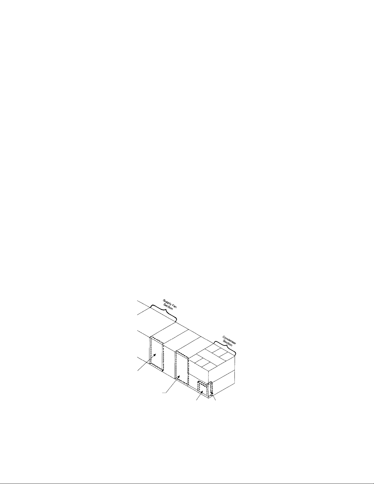
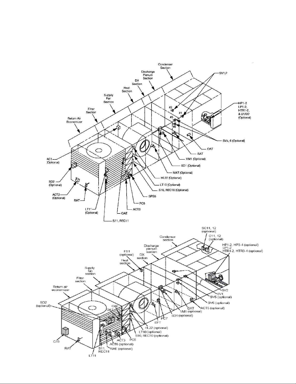
Control Locations
Current
Not Shown: Final filter section (Position I), Contains:
HL23- Gas Hi Limit
SP6- Clogged Filter Transducer
PC6- Clogged Filter Pressure Switch
Rooftop Units: RPS/RFS/RCS 015- 040 "C" Rev. AM 07/12 RPL 057117700 / Page 15
Page 16

Electrical Legend
Schematic Sym. Description Location
ACT1 Actuator Motor, Supply Fan Vanes Supply Air Section
ACT2 Actuator Motor, Return Fan Vanes Return Air Section
ACT3, 4 Actuator Motors, Economizer Dampers Economizer Section
ACT5 Actuator Motor, Discharge Isolation Damper Discharge Section
ACT6 Actuator Motor, Return Air Isolation Damper Return Air Section
ACT7 Actuator Motor, Heat Face/Bypass Coil Section, Heat
ACT8 Actuator Motor, Cool Face/Bypass Coil Section, Cool
ACT 10, 11 Actuator Motors, Exhaust Dampers Return Air Section
ACT12 Actuator Motor, Energy Recovery Bypass Damper Return Air Section
ADI ADI Board Main Control Box
AFD10 Adjustable Frequency Drive (Inverter), Supply Fan AFD or Supply Fan Sect.
AFD20 Adjustable Frequency Drive (Inverter), Return Fan AFD or Supply Fan Sect.
AFD60 Adjustable Frequency Drive (Inverter), Heat Wheel Energy Recovery Section
AS Blower Air Switch Furnace Section
BM Burner Blower Motor Furnace Section
C1, 5 Power Factor Capacitors, Compressor #1 Condenser Section
C2, 6 Power Factor Capacitors, Compressor #2 Condenser Section
C9, 10 Power Factor Capacitors, Supply Fan Supply Air Section
C11 Capacitor, Speedtrol (Circuit #1) Cond. Bulkhead
C19, 20 Power Factor Capacitors, Return Fan Return Air Fan
C21 Capacitor, Speedtrol (Circuit #2) Cond. Bulkhead
CB10 Circuit Breaker, Supply Fan Main Control Box
CB20 Circuit Breaker, Return Fan Main Control Box
CB60 Circuit Breaker, Heat Wheel Main Control Box
CCB1, 2 Compressor Control Boards Main or Cond. Ctl. Box
COMPR.1-4 Compressors Condenser Section
CPC Circuit Board, Main, MicroTech Controller Main Control Box
CPR Circuit Board, Expansion, Main Controller Main Control Box
CS1, 2 Control Switches, Refrigerant Circuits Condenser Control Box
DAT/SAT Discharge/Suppply Air Temperature Sensor Discharge/Supply Section
DFLH Design Flow Sensor, Left Hand Return Section
DFRH Design Flow Sensor, Right Hand Return Section
DHL Duct High Limit Main Control Box
DS1 Disconnect, Total Unit or Condenser/Heat Main Control Box
DS2 Disconnect, SAF/RAF/Controls Main Control Box
DS3 Disconnect, Electric Heat Electric Heat Section
DS4 Disconnect, Condenser Cond. Control Box
DS6 Disconnect, Unit Supplied Voltage Bulkhead
EAT Exhaust Air Temperature Sensor Return Air Section
EFT/MAT Entering/Mixed Air Temperature Sensor Supply Fan Section
EHB1 Staged Electric Heat Board Main Control Box
ERM1,2 Energy Recovery Wheel Motors Energy Recovery Section
EXPA, B, D Expansion Board Main Control Box
F1, 1A Fuse, Control Circuit, T1 Primary Main Control Box
F1C Fuse, Control Circuit, T1 Secondary Main Control Box
F2 Fuse, Control Circuit Condenser Control Box
F3 Fuse, Burner Motor Main Control Box
F4 Fuse, T4 Transformer Main Control Box
FB1,2 Fuseblocks, Compressor #1 & #2 Condenser/Fuse Ctrl Box
FB8 Fuseblock, Main Transformer Main Control Box
FB9, 10 Fuseblocks, Supply Fan Main Control Box
FB11-18 Fuseblocks, Condenser Fans Cond. Control Box
FB19, 20 Fuseblocks, Return Fan Main Control Box
Rooftop Units: RPS/RFS/RCS 015- 040 "C" Rev. AM 07/12 RPL 057117700 / Page 16
Page 17

Electrical Legend
Continued
Schematic Sym. Description Location
FB31-40 Fuseblocks, Electric Heat (Top Bank) Electric Heat Section
FB41-50 Fuseblocks, Electric Heat (Bottom Bank) Electric Heat Section
FD Flame Detector Furnace Section
FLC Fan Limit Control Furnace Section
FS1 Freezestat Coil Section, Heat/Cool
FS2 Freezestat Control Heat Section
FSG Flame Safeguard Furnace Section
GCB1 Generic Condenser Board Main Control Box
GFS1/GFR1 Ground Fault Sensor/Relay, RPS Unit Main Control Box
GFS2/GFR2 Ground Fault Sensor/Relay, RCS Unit Cond. Control Box
GFS4/GFR4 Ground Fault Sensor/Relay, RCS Unit Cond. Control Box
GRD Ground All Control Boxes
GV1 Gas Valve, Pilot Furnace Section
GV2, 3 Gas Valves, Main Furnace Section
GV4-8 Gas Valve, Hi-Turn Down Furnace Section
HL 1-10 High Limits, Elec. Heaters, Power (Top Bank) Electric Heat Section
HL 11-20 High Limits, Elec. Heaters, Power (Bottom Bank) Electric Heat Section
HL22 High Limit, Gas Heat (Prefilters) Supply Air Section
HL23 High Limit, Gas Heat (Final Filter) Final Filter Section
HL31-40 High Limits, Elec. Heaters, Control (Top Bank) Electric Heat Section
HL41-50 High Limits, Elec. Heaters, Control (Bottom Bank) Electric Heat Section
HP1-4 High Pressure Controls, Refrigerant On Compressors
HP5 High Pressure Control, Gas Furnace Section
HS1 Heat Switch, Electric, Shutdown Main Control Box
HTR1-4 Crankcase Heaters On Compressors
HUM1 Humidistat Sensor Energy Recovery Section
IT Ignition Transformer Furnace Section
LP1,2 Low Pressure Controls, Refrigerant On Compr.
LP5 Low Pressure Control, Gas Furnace Section
LT2 Light, Furnace On Furnace Section
LT3 Light, Pilot Gas Valve On Furnace Section
LT4 Light, Main Gas Valve On Furnace Section
LT10 Light, Supply Fan Supply Air Section
LT11 Light, Return Fan Return Air Section
LT12 Light, Heat Section Heat Section
LT13 Light, Filter Section Filter Section
LT14 Light, Final Filter Section Final Filter Section
LT15 Light, Discharge Section Discharge Section
LT16 Light, Blow-through Coil Section Blow-thru Coil Section
LT17 Light, Evaporator Coil Section Evaporator Coil Section
LT18 Light, Preheat Section Preheat Section
LT19 Light, Blank Section Blank Section
LT20 Light, Blank Compartment Blank Compartment
LT22 Light, Condenser Section Condenser Section
M1-6 Contactors, Compressors Main/Cond. Control Box
M9, 10 Contactors, Supply Fan Main Control Box
M11-18 Contactors, Condenser Fans, Circuit #1 Cond. Control Box
M19,20 Contactors, Return Fan Main Control Box
M21-28 Contactors, Condenser Fans, Circuit #2 Cond. Control Box
M29 Contactor, Burner Motor Furnace Section
M30 Contactor, Supply Fan Inverter Inverter Bypass Box
Rooftop Units: RPS/RFS/RCS 015- 040 "C" Rev. AM 07/12 RPL 057117700 / Page 17
Page 18

Electrical Legend
Continued
Schematic Sym. Description Location
M31-39 Contactors, Elec. Heaters (Top Bank) Electric Heat Section
M40 Contactor, Return Fan Inverter Inverter Bypass Box
M41-50 Contactors, Elec. Heaters (Bottom Bank) Electric Heat Section
MAT Mixed Air Temperature Sensor Supply Air Section
MCB Microprocessor Control Board Main Control Box
MCB1 Microprocessor Control Board #1 Main Control Box
MJ Mechanical Jumpers Terminal Blocks
MMP1-6 Manual Motor Protectors, Compressors Main/Cond. Control Box
MMP10 Manual Motor Protector, Supply Fan Main Control Box
MMP11, 12 Manual Motor Protectors, Condenser Fans Ckt. 1 Main/Cond. Control Box
MMP20 Manual Motor Protector, Return fan Main Control Box
MMP21,22 Manual Motor Protectors, Condenser Fans Ckt. 2 Main/Cond. Control Box
MMP60 Manual Motor Protector, Energy Recovery Wheel Energy Recovery Section
MP1-4 Motor Protectors, Compressors On Compressors
NB1, 2 Neutral Blocks Main Control Box
NB3 Neutral Block Cond. Control Box
OAE Outside Air Enthalpy Control Economizer Section
OAT Outside Air Temperature Sensor Discharge Bulkhead
OBA Output Board A, Standard Main Control Box
OBB Output Board B, Cooling Main Control Box
OBC Output Board C, Heating Main Controi Box
OL9, 10 Overload Relays, Supply Fan Main Controi Box
OL 19,20 Overload Relays, Return Fan Main Control Box
OP1-4 Oil Pressure Controls, Compressors Condenser Section
PB1 Powerblock, Total Unit or Cond./Heat Main Control Box
PB2 Powerblock, SAF/RAF/Controls Main Control Box
PB3 Powerblock, Electric Heat Electric Heat Section
PB4 Powerblock, Condenser Cond. Control Box
PC5 Pressure Control, Clogged Filter Filter Section
PC6 Pressure Control, Clogged Final Filter Final Filter Section
PC7 Pressure Control, Proof of Airflow Supply Air Filter
PC8 Pressure Control, Minimum Airflow Evaporator Coil Section
PC12, 22 Pressure Control, FanTrol Cond. Bulkhead
PM1 Phone Modem Main Control Box
PS1, 2 Pumpdown Switches, Refrigerant Circuits Cond. Control Box
PS3 Pumpdown Switch, Unit Main Control Box
PVM1 Phase Voltage Monitor, RPS Unit Main Control Box
PVM2, 4 Phase Voitage Monitor, RCS Unit Cond./Fuse Ctrl Box
R1, 2 Relays, High Pressure Reset Main/Cond. Control Box
R3, 4 Relays, Hi Presssure Delay Main/Cond. Control Box
R5- 8 Relays, Compressor, Safety/Cool Fail Main/Cond. Control Box
R9, 10 Relays, Compressor Lockout Main/Cond. Control Box
R11, 12 Relays, Low Ambient Main/Cond. Control Box
R19, 20 Relays, Cool Failure Indicator Main Control Box
R20 Relay, Gas, Steam, Hot Water Heat Main Control Box
R21, 22 Relays, Gas Heat Furnace Section
R23 Relay, Gas Heat, Modulating Valve or Electric Heat Furnace Sect./Elec. Ht. CB
R24 Relay, Gas Heat Alarm Main Control Box
R25 Relay, Gas Heat Start, Supply Fan Inverter Main Control Box
R26 Relay, Occupied/Unoccupied Main Control Box
R27 Relay, Exhaust Dampers Main Control Box
Rooftop Units: RPS/RFS/RCS 015- 040 "C" Rev. AM 07/12 RPL 057117700 / Page 18
Page 19

Electrical Legend
Continued
Schematic Sym. Description Location
R28 Relay, Isolation Dampers Main Control Box
R29 Relay, Remote Fire Alarm Main Control Box
R30 Relay, Cool Valve w/ F&B Main Control Box
R45 Relay, UV Lights Main Control Box
R46, 47 Relays, Supply Fan Inverter increase/decrease Main Control Box
R48, 49 Relays, Return fan Inverter increase/decrease Main Control Box
R58, 59 Relays, Energy Recovey Wheel- Inverter Main Control Box
R60 Relay, Energy Recovery Wheel- Enable Main Control Box
R61 Relay, Smoke Detector- Discharge Air Main Control Box
R62-64 Relays, Special Main Control Box
R63 Relay, Duct Hi- Limit Main Control Box
R66 Relay, RA Smoke Detector Main Control Box
R67 Relay, Supply Fan Enable Main Control Box
R68 Relay, Return Fan Enable Main Control Box
R69 Relay, Inverter Bypass VAV Box Interlock Main Control Box
R81- 88 Relay- Smoke Main Control Box
RAE Return Air Enthalpy Sensor Return Air Section
RAT Return Air Temperature Sensor Return Air Section
REC1 Receptacle, Main Box Main Control Box
REC2 Receptacle, Condenser Box Cond. Control Box
REC3 Receptacle, Field Power, 115V Discharge Bulkhead
REC10-23 Receptacles, Cabinet Section Cabinet Sections
S1 Switch, System On/Off, RPS Unit Main Control Box
S2 Switch, System On/Off, RCS Unit Cond. Control Box
S3 Switch, Furnace On/Off Furnace Section
S4 Switch, Inverter Bypass On/Off Main Control Box
S6 Switch, Return Fan Vanes Adjustment Main Control Box
S7 Switch, Local On/Off/Auto to Controller Main Control Box
S10-22 Switches, Cabinet Section Lights Cabinet Sections
S40-45 Switches, Door Interlock, UV Lights Cabinet Sections
SAT Supply Air Temperature Sensor Discharge Section
SB1 Staging Board #1, Cooling Main Control Box
SB2 Staging Board #2, Heating Main Control Box
SC11 Speed Control, Circuit #1 Cond. Bulkhead
SC21 Speed Control, Circuit #2 Cond. Bulkhead
SD1 Smoke Detector, Supply Air Discharge Section
SD2 Smoke Detector, Return Air Return Air Section
SPS1, 2, 3 Static Pressure Sensors, Duct or Building Main Control Box
SPS5 Static Pressure Sensor, Clogged Filter Filter Section
SPS6 Static Pressure Sensor, Clogged Final Filter Final Filter Section
SR1-3 Sequence Relays, Electric Heat Electric Heat Section
SV1,2 Solenoid Valves, Liquid Discharge Bulkhead
SV5, 6 Solenoid Valves, Hot Gas Discharge Bulkhead
T1 Transformer, Main Control Main Control Box
T2 Transformer, Unit 24V Main Control Box
T3 Transformer, Controller, 18V Main Control Box
T4 Transformer, Exhaust Dampers Main Control Box
T5 Transformer, Electric Heat Electric Heat Section
T6 Transformer, Unit Supplied Voltage Bulkhead
T7 Transformer, Gas Pilot Valve Furnace Section
T8 Transformer, Gas Main Valve Furnace Section
T9 Transformer, 24V Refrigerant Circuit Main Control Box
Rooftop Units: RPS/RFS/RCS 015- 040 "C" Rev. AM 07/12 RPL 057117700 / Page 19
Page 20

Electrical Legend
Continued
Schematic Sym. Description Location
T10 Transformer, SpeedTrol, 24V Cond. Control Box
T11 Transformer, Speedtrol, 230V Cond. Control Section
TB1 Terminal Block, 115V, Field Main/Cond. Control Box
TB2 Terminal Block, 24V, Field Main/Cond. Control Box
TB3,4 Terminal Blocks, Condenser Cond. Control Box
TB5 Terminal Block, 115V, Factory Main/Cond. Control Box
TB6 Terminal Block, 115V/24V, Factory Main Control Box
TB7, 8 Terminal Block, 24V, Factory Main Control Box
TB10 Terminal Block, Heating Main Control Box
TB11 Terminal Block, Heating Electric Heat Section
TB12, 13 Terminal Blocks, Electric Heat, Power Electric Heat Section
TC1, 2 Temperature Controls, FanTrol Cond. Control Box
TC12 Temperature Control, Fantrol Cond. Control Box
TD1, 2 Time Delays, Compressor Lockout Main/Cond. Control Box
TD3, 4 Time Delays, High Pressure Main/Cond. Control Box
TD5, 6 Time Delays, Compr. #1, #2, Part Winding Cond. Control Box
TD9 Time Delay, Supply Fan Part Winding Main Control Box
TD10 Time Delay, Hi-Turn Down Burner Furnace Section
TD11, 12 Time Delays, Low Ambient Cond. Control Box
TD19 Time Delays, Return Fan Part Winding Main Control Box
TD20 Time Delay, Return Air Fan Start Main Control Box
TR1, 2 Transducer, Pressure Main Control Box
U1,2 Unloaders, Compressors On Compressors
VM1 Valve Motor, Heating Heating Section
VM5 Valve Motor, Cooling Coil Section, Cool
VV1 Vent Valve Furnace Section
ZNT1 Zone Temperature Sensor, Control Field Installed
ZNT2-5 Zone Temperature Sensors, Special Field Installed
Rooftop Units: RPS/RFS/RCS 015- 040 "C" Rev. AM 07/12 RPL 057117700 / Page 20
Page 21

Section A1- Outdoor/Return Air Section
➩
Primary Codes that pertain: 19, 20, 21, 22, 23
Additional Codes that pertain: 06, 09, 12, 14, 15, 16, 17, 49
Codes 19 and 20 determine the base section. Code 19 is the Return Air Plenum, and determines if the unit has
back (a.k.a. horizontal) return air or bottom return air. The plenum is required for any outdoor air application
with an economizer (Code 20= BE, BY, DE, DY, EE, EY, FE, FY, GE or GY). The only case in which a plenum
is not required is when a 100% outdoor air damper and hood are ordered (C20= AE, AY).
Codes 21, 22, 23 determine the return air fan, motor and drives. These codes only pertain to units with a 0-100%
economizer (C20= DE, DY, EE, EY, FE, FY, GE or GY). The fan section parts, the fans, and the motors are listed
in this section. The drive components (fan sheave, motor sheave, belt, and fan bushing) are not listed as
they are unique to the unit. If a drive component is required you may use the number from the part and
cross reference it with the Drive Components Cross Reference form number: 571006, or contact Daikin
McQuay Parts to ensure that the needed part(s) are correctly identified. The motors range anywhere from
1- 10 horsepower, and the fan wheels range from 15" FC to 40" AF.
Code 06 determines the panels used in final cabinet assembly (return air units only).
Notes
Code 09, the voltage, is part of the motor part number identification.
Code 12, the control system comes into play when an economizer is present. The economizer comes with an
actuator motor on any MicroTech unit (C12= 1M, 2M, 4M, or 5M [original MicroTech] or L*, B*, E* or S* [MicroTech
II or MicroTech III]), but may not have a motor if the unit has controls by others (C12= YC or YM).
Code 14 determines if the return fan has an inverter, or variable frequency drive. If code 14 equals 1-9 (or X
for units built prior to 2000) , then the unit has inverters, and cannot, therefore have wheels with variable inlet
vanes (which haven't been used on production units since 2003).
Code 15, determines if Variable Inlet Vanes (VIV) are present (these haven't been used on production units since
2003). If code 15= 2, they are present on the return fan. VIV is only available on units with 0- 30% economizers
(C20= BE, BY).
Code 16 determines the smoke detector which is located in the return air cabinet. C16= 1 or 3 if a smoke detector
(SD2) is present.
Code 17 determines the Enthalpy Control. If C17= Y* and the unit has an economizer there is a mechanical
enthalpy control (OAE). If C17= C*, there is a differential enthalpy control (OAE + RAE).
Code 49 determines if the return air cabinet has a light, switch and receptacle (C49= B), fan belt guards (C49=
D) or both (C49= F).
Rooftop Units: RPS/RFS/RCS 015- 040 "C" Rev. AM 07/12 RPL 057117700 / Page 21
Page 22

Section A1- Outdoor/Return Air Section
100% Outside Air Damper with Hood
C20= AE or AY and C19= YY
No Return Air Plenum
4
6
14
Section B
100% Outdoor Air Damper w/ Hood (C20= AE, AY)
Ref Part Actuator
No. Description C20= AE C20= AY Qty.
4 Damper Assy Complete * 058440301 058440302 1
Damper Assy Only 098313601 098313601 1
6 Hood 058440303 058440303 1
14 Channel 058436501 058436501 1
* Complete assy. includes the damper assy. and linkage (no actuator) or actuator
assy.
Note: The outdoor air damper with actuator (C20= AE) must have MicroTech controls.
Dampers without actuators (C20= AY) must have controls by others (C12= YM, YC).
For Damper components see the following page.
Rooftop Units: RPS/RFS/RCS 015- 040 "C" Rev. AM 07/12 RPL 057117700 / Page 22
Page 23

Section A1- Outdoor/Return Air Section
100% Outside Air Damper with Hood
C20= AE or AY and C19= YY
Damper Detail
18
26
14
23
16
1
Damper Assy Detail
24
29
13 25
27
28
Manual
Linkage
Detail:
C20= AY
20
6
20
22
Motorized
Linkage
Detail:
C20= AE
1
6
31
7
21
4
21
4
1
7
Ref Part Actuator: ACT 3
No. Description C20= AE C20= AY Qty.
1 Damper Assy 098313601 098313601 1
4 Linkage Rod 067012700 067012700 1
6 Crank Arm Operator 046448600 not used 1
Arm Shaft not used 065371301 1
7 Linkage Rod 067012800 067012800 1
13 Damper Blade 044195101 044195101 12
14 Damper Seal 055616401 055616401 4
16 Damper Stop 065779801 065779801 2
18 Linkage Bar 047149800 047149800 2
20 Crank Arm 023680400 025072600 1
21 Ball Joint 000887000 000887000 4
22 Actuator Motor: ACT3 066534807 not used 1
23 Bushing 046098300 046098300 12
24 Bushing 043730400 043730400 24
25 Gasket 044193114 044193114 12
26 Gasket 045655714 046555714 1
27 Damper End Plug 041003501 041003501 12
28 Damper End Plug 041003502 041003502 6
29 Damper End Plug 041003503 041003503 6
31 Lock Collar not used 049115902 2
Rooftop Units: RPS/RFS/RCS 015- 040 "C" Rev. AM 07/12 RPL 057117700 / Page 23
Page 24

36
15
34
15
35
34
13
Section A1- Outdoor/Return Air Section
0- 30% Outside Air Section
C20= BE or BY and C19= BY or HY
Damper Detail
14
Linkage
30
13
Without
Actuator
C20= BY
1
1
Detail:
14
Linkage
Detail:
With
Actuator
C20= BE
31
32
43
33
11
42
10
8
9
26
Damper Detail
Ref Part Actuator: ACT 3
No. Description C20= BE C20= BY Qty.
Complete Assembly* 058440321 058440322 1
1 Damper Assy Only** 098314101 098314101 1
8 Damper Blade 044193213 044193213 2
9 Gasket 055940213 055940213 1
10 Gasket 044193132 044193132 2
11 End Seal 058456701 058456701 2
13 Motor Support 058456501 1
Rod Support Angle 055608601 1
14 Linkage Bar 058456601 058456601 1
15 Shaft Linkage 055536606 055536606 1
26 Exhaust Louver 096170531 096170531 1
Screen Only 058434301 058434301 2
30 End Plug 041003505 041003505 2
31 End Plug 041003506 041003506 2
32 Bushing 043730400 043730400 4
33 Bushing 046098300 046098300 4
34 Ball Joint 000887000 000887000 2
35 Actuator Motor ACT3 066534807 not used 1
36 Damper Crank Arm 023680400 not used 1
42 Screw- .19-24 x .75 046093803 046093803 4
43 Screw- .25-20 x 1.00 046296600 046296600 4
* Complete assy. includes the damper assy. and linkage (no actuator) or actuator assy.
** Damper only, no linkage or actuator components.
Rooftop Units: RPS/RFS/RCS 015- 040 "C" Rev. AM 07/12 RPL 057117700 / Page 24
Page 25
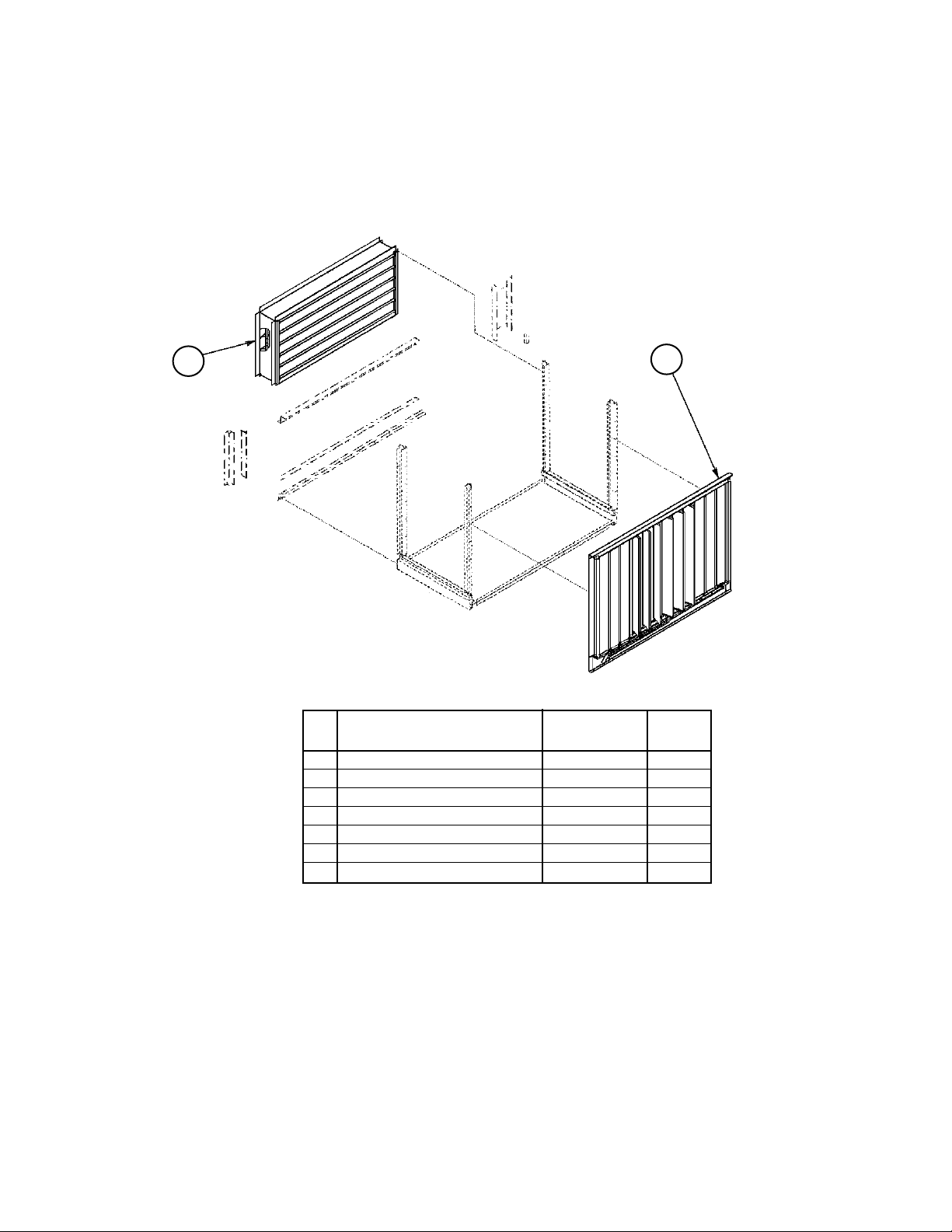
Section A1- Outdoor/Return Air Section
0- 100% Economizer Section with Barometric Exhaust Damper
Units without Return Air Fans
C20= DE, DY, EE, EY, FE, FY, GE, or GY, C21= YYYY
Back Return (C19= HY) shown.
12
11
Ref Part Part Qty.
No. Description Number
11 Economizer Damper 1
w/Act.(C20= *E) 058440311 1
w/o Act. (C20= *Y) 058440312 1
12 Exhaust Damper Assy 058440341 1
Damper Only 030049300 1
N/S Exhaust Louver 096170531 1
Louver Screen only 058434301 1
N/S= Not Shown on diagram.
1
Economizer with actuator (C20= *E) requires MicroTech Controls.
Without actuator (C20= *Y), requires controls by others (C12= YM, YC).
Economizer detail follows four pages after next.
Rooftop Units: RPS/RFS/RCS 015- 040 "C" Rev. AM 07/12 RPL 057117700 / Page 25
Page 26

Section A1- Outdoor/Return Air Section
0 - 100% Economizer Section with Exhaust Damper
Units with 15" Forward Curved Return Air Fans
C20= DE, DY, EE, EY, FE, FY, GE, or GY, C21= 15**
Unit Sizes 015C- 030C only
Until 12/04
57
12
Bottom Return
(C19= BY or BB or BE) shown.
55
166
150
58
55
11
Ref Part Part
No. Description Number Qty.
11 0- 100% Economizer
1
w/act. (C20= DE) 058440311 1
w/o act. (C20= DY) 058440312 1
12 Exhaust Louver
56
Until 5/00 058440331 1
5/00 & Later 096170531 1
Louver Screen Only 058434301 1
54 Gasket 023530463 1
55 Gasket 023530416 1
54
56 Gasket 020717911 1
57 Gasket 020717984 1
58 Exhaust Damper 058440353 1
150 Deflection Screen 046446600 1
166 Flange Bearing 001113500 2
N/S Isolation Damper
2
Code 19= BE only 058400861 1
N/S Belt Guard- LH 3 058440381 1
N/S Belt Guard- RH 3 058440382 1
N/S= Not Shown on diagram.
1
Economizer with actuator (C20= DE) requires MicroTech Controls.
Without actuator (C20= DY), requires controls by others. Economizer
detail after 40" fan section detail.
2
Isolation Damper detail follows Economizer detail.
3
Code 49= D or F.
12/04 and later
Ref Part Part
54
125
12
55
124
Bottom Return
(C19= BY or BB) shown.
Rooftop Units: RPS/RFS/RCS 015- 040 "C" Rev. AM 07/12 RPL 057117700 / Page 26
No. Description Number Qty.
11 0- 100% Economizer
1
w/act. (C20= DE) 058440311 1
w/o act. (C20= DY) 058440312 1
12 Damper Assy
Barometric (C20= DE,DY,FE,FY) 058440310 1
150
Power (C20= EE,EY,GE,GY) 058440320 1
Damper Only 112039627 1
54 Gasket 023530463 1
55 Gasket 023530416 2
124 Belt Guard- LH 2 058876301 1
11
125 Belt Guard- RH 2 058876302 1
150 Deflection Screen 046446600 1
N/S= Not Shown on diagram.
1
Economizer with actuator (C20= DE) requires MicroTech Controls.
Without actuator (C20= DY), requires controls by others. Economizer
detail after 40" fan section detail.
3
Code 49= D or F.
Page 27

Section A1- Outdoor/Return Air Section
0- 100% Economizer Section with Exhaust Damper
Units with 30" Air Foil Return Air Fans
C20= DE, DY, EE, EY, FE, FY, GE, or GY, C21= 30**
Until 12/04
12
45
16
Back Return (C19= HY)
shown.
44
124
11
17
Ref Part Part
No. Description Number Qty.
11 0- 100% Economizer
1
w/act. (C20= DE) 058440311 1
w/o act. (C20= DY) 058440312 1
12 Exhaust Damper Assy 058440361 1
Damper Blade only 058497701 1
Grille- Damper Hood 058560701 1
125
Gasket- Blade 020717938 1
16 Gasket- Retainer 2 058582004 1
17 Gasket- Retainer 2 058582003 1
44 Gasket- Retainer 2 058582006 1
45 Gasket- Retainer 2 058582005 1
124 Belt Guard- LH 3 059864401 1
125 Belt Guard- RH 3 059864402 1
1
Economizer with actuator (C20= DE) requires MicroTech Controls.
Without actuator (C20= DY), requires controls by others (C12= YM, YC).
Economizer detail on page after next.
3
Not applicable for units with Bottom Return (Code 19= BY or BB)
3
Code 49= D or F.
12/04 and later
12
55
50
55
11
Bottom Return (C19= BY or BB) shown.
Rooftop Units: RPS/RFS/RCS 015- 040 "C" Rev. AM 07/12 RPL 057117700 / Page 27
Ref Part Part
No. Description Number Qty.
11 0- 100% Economizer
1
w/act. (C20= DE) 058440311 1
w/o act. (C20= DY) 058440312 1
12 Damper Assy
Barometric (C20= DE,DY,FE,FY) 058440310 1
Power (C20= EE,EY,GE,GY) 058440320 1
Damper Only 112039627 1
50 Belt Guard 2 058400888 2
55 Gasket 055921422 2
1
Economizer with actuator (C20= DE) requires MicroTech Controls.
Without actuator (C20= DY), requires controls by others (C12= YM, YC).
Economizer detail on page after next.
2
Code 49= D or F.
Page 28

Section A1- Outdoor/Return Air Section
0- 100% Economizer Section with Exhaust Damper
Units with 40" Air Foil Return Air Fans
C20= DE, DY, EE, EY, FE, FY, GE, or GY, C21= 40**
Until 12/04
150
12
57
Bottom Return (C19= BY or
BB) is only option for 40" RF.
48
49
49
55
Unit Sizes 036C- 040C only
Ref Part Part
No. Description Number Qty.
11 0- 100% Economizer
w/act. (C20= DE) 058440311 1
w/o act. (C20= DY) 058440312 1
12 Exhaust Damper Assy 058440371 1
Damper Blade only 058451901 1
Grille- Damper Hood 038238001 1
Gasket- Blade 020717987 1
11
Gasket- Blade Ends 020717920 2
48 Gasket- Retainer 058594701 1
49 Gasket- Retainer 058594601 1
55 Gasket 055582601 2
57 Gasket 055582601 1
150 Deflection Screen 046446600 1
N/S Belt Guard- Small 2 058440383 2
N/S Belt Guard- Large 2 058400888 2
N/S= Not Shown on diagram.
1
Economizer with actuator (C20= DE) requires MicroTech Controls.
Without actuator (C20= DY), requires controls by others (C12= YM, YC).
Economizer detail on page after next.
2
Code 49= D or F.
1
12/04 and later
12
55
124
50
55
Bottom Return (C19= BY or BB)
is only option for 40" RF.
Rooftop Units: RPS/RFS/RCS 015- 040 "C" Rev. AM 07/12 RPL 057117700 / Page 28
Ref Part Part
No. Description Number Qty.
11 0- 100% Economizer
1
w/act. (C20= DE) 058440311 1
w/o act. (C20= DY) 058440312 1
12 Damper Assy
Barometric (C20= DE,DY,FE,FY) 058440314 1
Power (C20= EE,EY,GE,GY) 058440324 1
Damper Only 112039627 1
50 Belt Guard 2 058400888 2
55 Gasket 055921422 2
124 Fan Guard 2 058440384 2
1
11
Economizer with actuator (C20= DE) requires MicroTech Controls.
Without actuator (C20= DY), requires controls by others (C12= YM, YC).
Economizer detail on page after next.
2
Code 49= D or F.
Page 29

Section A1- Outdoor/Return Air Section
0- 100% Economizer Assembly
C20= D*, E*, F*, G*
Diagram
17
18
12
14
26
3
23
10
Shown with Actuator
C20= DE, EE, FE, GE
All parts shown apply to economizers
without actuators except for those in the
9
dotted line box. Units with Actuator must
have MicroTech Controls.
13 25 27 28
12
29
15
11
22
20
21
7
6
4
21
Without Actuator
19
24
20
C20= DY, EY, FY, GY
C12 must= YM or YC
Rooftop Units: RPS/RFS/RCS 015- 040 "C" Rev. AM 07/12 RPL 057117700 / Page 29
16
8
6
11
721
17
421
Page 30

Section A1- Outdoor/Return Air Section
0- 100% Economizer Assembly
C20= DE, DY, EE, EY, FE, FY, GE, GY
Components
0-100% Economizer Detail
Ref Part Actuator: ACT 4
No. Description C20= DE C20= DY Qty.
Complete Assembly 058440311 058440312 1
3 Channel 058440313 058440313 1
4 Linkage Rod 067012700 067012700 1
6 Crank Arm Operator 046448600 1
Arm Shaft 065371301 1
7 Linkage Rod 067012800 067012800 1
8 Bottom Support 058448201 058448201 1
9 Top Support 058448401 058448401 1
10 Block Off 058449601 058449601 1
11 Motor Mount 060063301 1
Rear Bearing Support 066002101 1
12 Side Support 058448301 058448301 2
13 Damper Blade 044195101 044195101 12
14 Outside Seal 043734500 043734500 4
15 Center Seal 043734400 043734400 2
16 Damper Stop 065779801 065779801 4
17 Motor Support Brkt. 058411302 1
Front Bearing Supp. 066002201 1
18 Linkage Bar 044194800 044194800 2
19 Linkage Bar 044194900 044194900 2
20 Crank Arm 023680400 025072600 1
21 Ball Joint 000887000 000887000 4
22 Actuator Motor ACT4 066534807 1
23 Bushing 046098300 046098300 12
24 Bushing 043730400 043730400 24
25 Gasket 044193114 044193114 12
26 Gasket 045655714 045655714 2
27 End Plug 041003501 041003501 12
28 End Plug 041003502 041003502 6
29 End Plug 041003503 041003503 6
Rooftop Units: RPS/RFS/RCS 015- 040 "C" Rev. AM 07/12 RPL 057117700 / Page 30
Page 31

Section A1- Outdoor/Return Air Section
Return Air Plenum Isolation Damper w/ Actuator ACT6
C19= BE- Assembly # 058400861
C21= 15F*
Unit Sizes 015- 030 only
9
4
3
10
6
7
8
5
8
2
11
Damper Components
Ref Part Part Qty.
No. Description Number
2 Damper Assembly 033507402 1
3 Motor Mount 058868401 1
4 Actuator Motor ACT6 031771701 1
5 Damper Rod 028680909 1
6 Damper Ball Joint 000887000 2
7 Crank Arm 032279200 1
8 Screw 001378300 14
9 Screw 040501405 3
10 Damper Angle 058412601 2
11 Damper Angle 058412701 2
Rooftop Units: RPS/RFS/RCS 015- 040 "C" Rev. AM 07/12 RPL 057117700 / Page 31
Page 32

Section A1- Outdoor/Return Air Section
LH Louvered Door Assy
Section Final
Assembly
Design Flow Detail
Code 20= FE, FY, GE, GY
Louvered Door
Assembly Detail
➤
3
2
RH Louvered Door Assy
105
9
127
➤
12
110
104
106
Design Flow Vane and
Vane Bearings Detail
Ref Part Part Qty.
No. Description Number
1 Louver Panel Units with no Return Fan (40" Door) Left Hand Door 058410204 7
Units with no Return Fan (40" Door) Right Hand Door 058410203 7
Units with 30" or 40" Return Fan (52" Door) Left Hand Door 058410104 7
Units with 30" or 40" Return Fan (52" Door) Right Hand Door 058410103 7
2 Grille Units with no Return Fan (40" Door) 058410401 1
Units with 30" or 40" Return Fan (52" Door) 058564001 1
3 Gasket 026172804 3
9 Potentiometer 098663701 1
12 O-Ring- Potentiometer 098663801 1
104 Panel- Vane 098661801 1
105 Shaft- Upper 098662601 1
106 Bearing- Lower 091634501 1
109 Crank Arm Assy Left Hand Door 091658802 1
Crank Arm Assy Right Hand Door 091658801 1
110 Link Arm
120 Bearing 060014201 1
127 Bearing 047138535 1
130 Spring- Main 098664801 1
131 Spring- Secondary 098664901 1
N/S Leveling Kit- Design Flow 091659301 1
1
P/N is unit specific. Contact Daikin McQuay Parts with overall length and bolt hole spacing so that the correct part
can be identified.
120
Adjuster Control Assy
Detail
109 104
1
1
1
131
130
Spring
Detail
Rooftop Units: RPS/RFS/RCS 015- 040 "C" Rev. AM 07/12 RPL 057117700 / Page 32
Page 33

91
21
60
Section A1- Outdoor/Return Air Section
Return Air Fan Mounting- 15" Forward Curved Fan
Code 21= 15F1, 15F2, 15F3
Rubber-In-Shear Code 21= 15F1
Rubber Mount Detail: All four corners are the same.
90
Return
Drawing is common to all four corners.
91
Spring Mounting Code 21= 15F2 and Seismic Mount Code 21= 15F3
Ref Part Part Qty.
Fan
No. Description Number
Base
21 Support Angle 035205200 1
60 Isolator- RP- 3 Red 021639701 1
90 Screw 040499501 2
91 Nut 032333305 3
Quantities listed are for ONE mount.
Spring Detail: Quantities listed in chart are for ONE spring. Seismic
mounting is the same with the addition of the parts shown below.
60
99C
99D
56
Pos. 3
Pos. 4
➤
Air Flow
spring- see below
Pos. 2
99B
Top View
Pos.1
99A
55
Additional Seismic Restraint Parts
72
Base Channel
67
Angle
Raceway
71
70
69
Ref Part Part Qty
No. Description Number
55 Spring Retainer 035204301 1
56 Washer 035204500 1
60 Pad 035204400 1
99A Spring Isolator- Position 1
Motor H.P.= 1 thru 5 Black 022611100 1
Motor H.P.= 7.5 thru 10 Blue 022611200 1
99B Spring Isolator- Position 2
Motor H.P.= 1 thru 2 Black 022611100 1
Motor H.P.= 3 thru 7.5 Blue 022611200 1
Motor H.P.= 10 Yellow 022611300 1
99C Spring Isolator- Position 3
Motor H.P.= 1 thru 5 Black 022611100 1
Motor H.P.= 7.5 thru 10 Blue 022611200 1
99D Spring Isolator- Position 4
Motor H.P.= All Black 022611100 1
1
Quantity is for ONE corner. All four corners are the same.
Ref Part Part Qty
No. Description Number
67 Washer Code 21= 15F3 only 057276701 1
68 Spacer Code 21= 15F3 only 057276801 1
69 Washer- Neoprene Code 21= 15F3 only 067301101 2
70 Spacer- Neoprene Code 21= 15F3 only 067301201 1
71 Cap Screw Code 21= 15F3 only 040499515 1
72 Lock Washer Code 21= 15F3 only 048164816 1
1
Quantity is for ONE corner. All four corners are the same.
1
1
68
Rooftop Units: RPS/RFS/RCS 015- 040 "C" Rev. AM 07/12 RPL 057117700 / Page 33
Page 34

Section A1- Outdoor/Return Air Section
Return Air Fan Mounting- 30" and 40" Airfoil Fan
Code 21= 30*1, 40*1, 30*2, 40*2, 30*3, 40*3
Until 12/04 (original fan design)
Rubber-In-Shear Code 21= 30*1, 40*1
Return
Fan
Ref Part Part Qty.
Base
No. Description Number
21 Support Angle 035205200 1
60 Isolator- RP- 3 Black 021639704 1
21
91
90
90 Screw 040499501 2
91 Nut 032333305 3
Drawing is common to all four corners.
60
91
Quantities listed are for ONE mount.
Spring Mounting Code 21= 30*2, 40*2 and Seismic Mount Code 21= 30*3, 40*3
Spring Detail: Quantities listed in chart are for ONE spring. Seismic
mounting is the same with the addition of the parts shown below.
Rubber Mount Detail: All four corners are the same.
60
99C
99D
56
Pos. 3
Pos. 4
➤
Air Flow
spring- see below
Pos. 2
99B
Top View
Pos. 1
99A
55
Additional Seismic Restraint Parts
72
Base Channel
67
Angle
Raceway
71
70
69
68
Ref Part 30" 40" Qty
No. Description Fan Fan
55 Spring Retainer 035204301 035204301 1
56 Washer 035204500 035204500 1
60 Pad 035204400 035204400 1
99A Spring Isolator- Position 1
Motor H.P.= 1 thru 5 022611200 022611200 1
Motor H.P.= 7.5 thru 10 022611300 022611200 1
99B Spring Isolator- Position 2
Motor H.P.= 1 thru 5 022611300 022611300 1
Motor H.P.= 7.5 thru 10 022611400 022611300 1
99C Spring Isolator- Position 3
Motor H.P.= 1 thru 5 022611100 022611100 1
Motor H.P.= 7.5 thru 10 022611200 022611100 1
99D Spring Isolator- Position 4
Motor H.P.= All 022611100 022611100 1
NOTE: Spring colors— 022611100= Black; 022611200= Blue; 022611300= Yellow;
022611400= Brown.
1
Quantity is for ONE corner. All four corners are the same.
Ref Part Part Qty
No. Description Number
67 Washer Code 21= 30/40*3 only 057276701 1
68 Spacer Code 21= 30/40*3 only 057276801 1
69 Washer- Neoprene Code 21= 30/40*3 only 067301101 2
70 Spacer- Neoprene Code 21= 30/40*3 only 067301201 1
71 Cap Screw Code 21= 30/40*3 only 040499515 1
72 Lock Washer Code 21= 30/40*3 only 048164816 1
1
Quantity is for ONE corner. All four corners are the same.
1
1
Rooftop Units: RPS/RFS/RCS 015- 040 "C" Rev. AM 07/12 RPL 057117700 / Page 34
Page 35

91
21
60
Section A1- Outdoor/Return Air Section
Return Air Fan Mounting- 30" and 40" Airfoil Fan
Code 21= 30B1, 40B1, 30B2, 40B2, 30B3, 40B3
12/04 and later (current fan design)
Rubber-In-Shear Code 21= 30*1, 40*1
90
Return
Fan
Base
Ref Part Part Qty.
No. Description Number
21 Support Angle 035205200 1
60 Isolator RP- 3 Black 021639704 1
91
Drawing is common to all four corners.
Quantities listed are for ONE mount.
90 Screw 040499501 2
91 Nut 032333305 3
Rubber Mount Detail: All four corners are the same.
Spring Mounting Code 21= 30*2, 40W*2 and Seismic Mount Code 21= 30*3, 40*3
Spring Detail: Quantities listed in chart are for ONE spring.
Ref Part 30" 40" Qty
No. Description Fan Fan
89
88
81
63
64
Pos. 2
Top View
Pos. 1
21
61
62
spring-
see
below
Pos. 3
Air Flow
Pos. 4
21 Mount- Spring
Spring Mount- C21= ***2 251783201 251783201 1
Seismic Mount- C21= ***3 251783301 251783301 1
81 Nut
Spring Mount- C21= ***2 059992201 059992201 3
Seismic Mount- C21= ****3 111056301 111056301 5
88 Nut 040500002 040500002 1
89 Screw
Spring Mount- C21= ****2 112047201 112047201 3
Seismic Mount- C21= ****3 112047201 112047201 5
61 Spring Isolator- Position 3
Motor H.P.= 1 thru 3 251784601 251784701 1
Motor H.P.= 5 251784701 251784701 1
Motor H.P.= 7.5 thru 10 251784701 251784801 1
62 Spring Isolator- Position 4
Motor H.P.= 1 thru 5 251784401 251784501 1
Motor H.P.= 7.5 thru 10 251784401 251784601 1
63 Spring Isolator- Position 2
➤
Motor H.P.= 1 thru 5 251784601 251784601 1
Motor H.P.= 7.5 thru 10 251784701 251784701 1
64 Spring Isolator- Position 1
Motor H.P.= All 251784401 251784501 1
NOTE: Spring colors— 251784401= Blue; 251784501= Yellow; 251784601= Black;
251784701= Purple; 251784801= Brown.
1
Quantity is for ONE corner. All four corners are the same.
1
Rooftop Units: RPS/RFS/RCS 015- 040 "C" Rev. AM 07/12 RPL 057117700 / Page 35
Page 36

Section A1- Outdoor/Return Air Section
Return Air Fan Deck
15" Fans: C21= 15F1, 15F2 or 15F3
Diagrams
End View
27
15
13
Motor
18
7
6
8
15
20
21
26
15
20
13
Rear View
1916
Ref Part Part
No. Description Number Qty.
6 Wheel 033135100 2
7 Motor Shelf 033262600 1
8 Filler Piece 033262400 1
13 Shaft 033262001 1
15 Tube Coupling 021213700 3
16 Tube Coupling 021213800 3
18 Tube Clamp 001324600 4
19 Grease Fitting 000109800 1
20 Ball Bearing 020648601 3
21 Shim
26 Key 023221409 2
27 Key 023221405 1
Note: Motors are listed on a separate page after the fan deck details.
1
Shims are used as needed. Any of the following may be used:
025639900 (.058"); 091531301 (.046"); 091531601 (0.22"); 091531501
(.031").
Rooftop Units: RPS/RFS/RCS 015- 040 "C" Rev. AM 07/12 RPL 057117700 / Page 36
1
3
Page 37

Section A1- Outdoor/Return Air Section
Return Air Fan Deck
30" Fans: C21= 30W* or 30B*
Until 12/04
Shown With
Variable Inlet Vanes
15
16
48
49
23
14
9
12
20
10
46
21
26
13
27
49
48
6
7
Motor
2
Ref Part w/o VIV w/VIV Qty.
No. Description C21= 30B* C21= 30W*
2 Inlet Funnel 031940902 032739400 1
6 Fan Wheel- SISW 066543221 066543221 1
7 Motor Shelf 058573201 058573201 1
9 Seal Plate n/a 059363801 1
10 Linkage Arm n/a 059364101 1
12 Linkage Rod- Adjust. n/a 059363501 1
13 Shaft 058568201 058568201 1
14 Actuator Motor: ACT2 n/a 031771701 1
15 Crank Arm n/a 032279200 1
16 Ball Joint n/a 000887000 1
20 Cover Plate 059364202
Seal Angle 059363402 1
21 Grease Fitting 000109800 000109800 2
23 Ball Bearing 020648601 020648601 2
26 Shaft Key 023221405 023221405 1
27 Shaft Key 023221411 023221411 1
46 Sleeve Bearing n/a 047138509 1
48 Retainer Assembly 058582001 058582001 1
Gasket Only 055582601 055582601 1
49 Retainer Assembly 058582002 058582002 2
Gasket Only 055582601 055582601 2
Note: Motors are listed on a separate page after the fan deck details.
Rooftop Units: RPS/RFS/RCS 015- 040 "C" Rev. AM 07/12 RPL 057117700 / Page 37
Page 38

Section A1- Outdoor/Return Air Section
Return Air Fan Deck
30" Fans: C21= 30B1, 30B2 OR 30B3
12/04 & Later
1
1719
13
2627
6
2
17 1
19
Ref Part Part Qty.
No. Description Number
1 Bearing 020648601 2
2 Funnel- Inlet 031940902 1
6 Wheel- Fan 066543221 1
7 Mount- Motor 058400974 1
13 Shaft- Fan 058568201 1
17 Tubing- Plastic 021136745 2
19 Fitting- Grease 000109800 2
26 Key 023221405 1
27 Key 023221411 1
Note: Motors are listed on a separate page after the fan deck
details.
Motor
7
Rooftop Units: RPS/RFS/RCS 015- 040 "C" Rev. AM 07/12 RPL 057117700 / Page 38
Page 39

Section A1- Outdoor/Return Air Section
Return Air Fan Deck
40" Fans: C21= 40W* or 40B*
Until 12/04
Motor
7
19
27
13
20
10
21
26 6
56
61
Actuating
Lever
57
60
V.I.V. Linkage
2
1516
V.I.V. Actuator
Motor and Crank Arm
Linkage Rod
Viewed from Bottom of Fan
Funnel
1
4
5
Ref Part w/o VIV w/VIV Qty.
No. Description C21= 40B* C21= 40W*
1 Motor Shelf n/a 038236400 1
2 Inlet Funnel 031940905 032739700 1
4 Crank Arm n/a 032279200 1
5 Actuator Motor ACT2 n/a 031771701 1
6 Fan Wheel: SISW 066543242 066543242 1
7 Fan Motor Mount 038234401 038234401 1
10 Bearing Plate 038234800 038234800 1
13 Shaft 037788701 037788701 1
15 Coupling 027674000 027674000 3
16 Coupling 027674100 027674100 3
19 Grease Fitting 000109800 000109800 2
20 Bearing 020648603 020648603 2
21 Shim 021494400 021494400 2
26 Shaft Key 023221508 023221508 1
27 Shaft Key 023221507 023221507 1
56 Linkage Rod n/a 034831722 1
57 Ball Joint Damper n/a 027671100 1
60 Turnbuckle n/a 032851100 1
61 Ball Joint Damper n/a 034256500 1
Note: Motors are listed on a separate page after the fan deck details.
Rooftop Units: RPS/RFS/RCS 015- 040 "C" Rev. AM 07/12 RPL 057117700 / Page 39
Page 40

Section A1- Outdoor/Return Air Section
Return Air Fan Deck
40" Fans: C21= 40B1, 40B2 OR 40B3
12/04 & Later
18
1
6
17
Motor
7
13
2627
2
1
Ref Part Part Qty.
No. Description Number
1 Bearing 020648603 2
2 Funnel- Inlet 031940905 1
6 Wheel- Fan 066543232 1
7 Mount- Motor 058400974 1
13 Shaft- Fan 037788701 1
17 Tubing- Plastic 021136745 2
18 Fitting- Grease 000109800 2
26 Key 023221508 1
27 Key 023221507 1
Note: Motors are listed on the following page.
17
18
Rooftop Units: RPS/RFS/RCS 015- 040 "C" Rev. AM 07/12 RPL 057117700 / Page 40
Page 41

Section A1- Outdoor/Return Air Section
Return Air Fan Motors
Motors
H.P. Unit ODP ODP HiEff ODP PrEff. TEFC TEFC HiEff TEFC PrEff
Voltage C22= *AY C22= *EY C22= *JY C22= *GY C22= *HY C22= *KY
C09= 12
1 208/60/3 020520800 039447400 205167600 025431900 049100100 004735000
1.5 208/60/3 020520900 039442200 205167500 025432900 049100200 N/A
2 208/60/3 020524900 039895700 046515500 025433900 049100300 N/A
3 208/60/3 020521800 039447500 065817100 025435000 047358100 065819400
5 208/60/3 020521000 039447600 065817200 025435800 049186800 065819500
7.5 208/60/3 020524800 037530300 065817300 024581000 047665900 065819600
10 208/60/3 021486000 038999000 065817400 025436900 047666100 065819700
C09= 29
1 230/60/3 019664600 039446200 205162800 020242000 040161000 046513000
1.5 230/60/3 019423600 039442300 046511100 025433000 040161100 046513100
2 230/60/3 019854800 039446300 205163500 021062900 047446000 073321000
3 230/60/3 017859700 039442400 065818100 020956000 049262300 065820100
5 230/60/3 019664800 039442500 065818200 020520600 040161200 065820200
7.5 230/60/3 019855100 039448700 065818300 020522100 049100500 065820300
10 230/60/3 017859600 039446500 065818400 024211500 044691100 065820400
C09= 27
1 460/60/3 019664600 039446200 205162800 020242000 040161000 046513000
1.5 460/60/3 019423600 039442300 046511100 025433000 040161100 046513100
2 460/60/3 019854800 039446300 205163500 021062900 047446000 073321000
3 460/60/3 017859700 039442400 065818100 020956000 049262300 065820100
5 460/60/3 019664800 039442500 065818200 020520600 040161200 065820200
7.5 460/60/3 019855100 039448700 065818300 020522100 049100500 065820300
10 460/60/3 017859600 039446500 065818400 024211500 044691100 065820400
C09= 37
1 575/60/3 027677700 049180800 206500900 049184500 049188000 206505600
1.5 575/60/3 047132100 049180900 206501600 039897800 049188100 205167800
2 575/60/3 046749300 049181000 205168300 048169800 049188200 046514400
3 575/60/3 046741700 046741600 046511700 033148000 049188300 046514500
5 575/60/3 046741800 046741900 205168900 048169900 049188400 046514600
7.5 575/60/3 046744400 047443300 205168800 040160100 049188500 046514700
10 575/60/3 031326700 047443400 205168600 049763700 049188600 065821400
Rooftop Units: RPS/RFS/RCS 015- 040 "C" Rev. AM 07/12 RPL 057117700 / Page 41
Page 42

Section A1- Outdoor/Return Air Section
Section Mounted Controls
OAE, RAE, LT11, S11, REC11
Bottom Return
Shown
C19= BY or BE
Economizer
Bottom Return
Shown
C19= BY or BE
Economizer
4342
40
7
40
41
41
OAE- Mechanical Enthalpy (Code 17= Y*)
Ref Part Part
No. Description Number Qty.
40 Mount- OAE Enthalpy 055800101 1
41 Enthalpy Assembly
(knob & Control) 055740691 1
Knob only 026215500 1
Control OAE only 030706702 1
OAE & RAE Differential Enthalpy (Code 17= C*)
Ref Part Part
No. Description Number Qty.
40 Mount- OAE Enthalpy 059328901 1
41 Control- OAE 049262201 1
42 Mount- RAE Enthalpy
Back Air Return 055800501 1
Bottom Air Return 055732301 1
43 Control- RAE 049262202 1
RAT- Return Air Temperature Sensor
Ref Part Part
No. Description Number Qty.
7 Sensor- RAT 193414601 1 1
1
P/N is for MicroTech III Controls. For Original MicroTech controls
(C12= 1,2,3,4,5) use p/n 065829505. For MicroTech II controls
(C12= _D or _S) use p/n 060004705.
30
30
SD2- Return Air Smoke Detector
C16= 1 or 3
Ref Part Part
No. Description Number Qty.
Return Air Opening
Return Air
Opening
30 Smoke Detector SD2
until 2/00 055744901 1 1
2/00- 2/03 060016501 1
Back Return
C19= HY
Bottom Return
C19= BY or BE
2/03- Present 098873101 1
1
Includes Duct House 24- 240V p/n 049025003 + Smoke Detector
only p/n 049025004.
LT11- Return Fan Light/S11- Return Fan Light
Switch/ REC11- Return Fan Light Receptacle
84 85
88 89
Rooftop Units: RPS/RFS/RCS 015- 040 "C" Rev. AM 07/12 RPL 057117700 / Page 42
C49= E or F
Ref Part Part
No. Description Number Qty.
84 Light Fixture 042229500 1
85 Bulb- LT11 065492402 1
88 Light Switch- S11 065492201 1
89 Receptacle- REC11 030187000 1
Page 43

Section A2- Outdoor/Return/Heat Recovery Air Section
Notes
➩
Primary Codes that pertain: 19, 20, 21, 22, 23, 24
Additional Codes that pertain: 06, 09, 14, 15, 16, 17, 49
Codes 19 and 20 determine the base section. Code 19 is the Return Air Plenum, and is always BY (bottom return
air). Code 20 determines the type of Outdoor Air/Heat Recovery control is used. C20= 1E or 2E are 100% OA
Air units, and if C20= 3E the unit has an economizer.
Codes 21, 22, 23 determine the return air fan, motor and drives. The fan section parts, the fans, and the motors
are listed in this section.The drive components (fan sheave, motor sheave, belt, and fan bushing) are not
listed as they are unique to the unit. If a drive component is required you may use the number from
the part and cross reference it with the Drive Components Cross Reference form number: 571006, or
contact Daikin McQuay Parts to ensure that the needed part(s) are correctly identified. The motors range
anywhere from 1.5- 20 horsepower, and the fan is a 24" Single width airfoil wheel.
Code 24 determines if the Heat Wheel has a frost protection inverter (mounted in the section).
Code 06 determines the panels used in final cabinet assembly.
Code 09, the voltage, is part of the motor part number identification.
Code 14 determines if the return fan has an inverter, or variable frequency drive. If code 14 equals 2-9 , then
the unit has a return fan inverter.
Code 15, determines the type of Return Fan inverter (mounted in a separate section or the supply air section).
Code 16 determines the smoke detector which is located in the return air cabinet. C16= 1 or 3 if a smoke detector
(SD2) is present.
Code 17 determines the Enthalpy Control. If C17= Y* and the unit has an economizer there is a mechanical
enthalpy control (OAE). If C17= C*, there is a differential enthalpy control (OAE + RAE).
Code 49 determines if the return air cabinet has a light, switch and receptacle (C49= E).
Rooftop Units: RPS/RFS/RCS 015- 040 "C" Rev. AM 07/12 RPL 057117700 / Page 43
Page 44

Section A2- Outdoor/Return/Heat Recovery Air Section
100% Outside Air Low Flow - C20=1E
Intake Hood (see detail to left)
140
148
148
160
142
155
144
145
146
141
1
Outdoor Air Intake Hood
Detail
or
419418
161
LH
RH
422
Exhaust Hood
Detail
12
201
202
206
204
Ref Part Part
No. Description Number Qty.
1 Fan Assembly 1
12 Damper Assy- Low Leak 2 MicroTech II Controls 110905001 1
Damper Assy- Low Leak 3 MicroTech III Controls 110905009 1
140 Panel, Top- Hood 111066001 1
141 Panel, LH Side- Outdoor Air Intake Hood 111066101 1
142 Panel, RH Side- Outdoor Air Intake Hood 111066601 1
144 Panel, Louver- Outdoor Air Intake Hood 111066301 1
145 Panel, Louver- Outdoor Air Intake Hood 111066401 1
146 Panel, Lower Louver- Outdoor Air Intake Hood 111066501 1
148 Screen- Outdoor Air Intake Hood 111076501 2
155 Gasket 024476500 8 ft.
160 Wheel, Enthalpy- Heat Recovery
161 Motor- Enthalpy Wheel
162 Sheave- Fixed
4
1
4
1
4
1
201 Filter Rack 110907301 1
202 Filter Rack 110907302 1
204 Filter Rack 110907304 1
206 Filter Rack 110907306 1
418 Door, Indented- Exhaust LH 111201841 1
419 Door, Indented- Exhaust RH 111201842 1
422 Exhaust Hood 111069501 2
N/S Filter 16 x 20 x 2 031298001 12
N/S Filter 16 x 25 x 2 031298002 12
N/S= Not Shown on Diagram.
1
See Detail two pages after next.
2
See Detail five pages after next.
3
See Detail six pages after next.
4
See Detail in this section (A2) titled 'Heat Recovery-Enthalpy-Wheel Detail (Ref #160) Wheel Motor, Drive Components, Seals"
162
Rooftop Units: RPS/RFS/RCS 015- 040 "C" Rev. AM 07/12 RPL 057117700 / Page 44
Page 45

Section A2- Outdoor/Return/Heat Recovery Air Section
100% Outside Air High Flow - C20=2E
140
Hood (see detail to left)
148
148
142
144
145
146
141
Outdoor Air Intake Hood
Detail
or
419418
LH
RH
201
202
1
161
12
162
422
Exhaust Hood
Detail
203
204
Ref Part Part
No. Description Number Qty.
1 Fan Assembly 1
12 Damper Assy- Low Leak 2 MicroTech II Controls 110905001 1
Damper Assy- Low Leak 3 MicroTech III Controls 110905009 1
140 Panel, Top- Hood 111066001 1
141 Panel, LH Side- Outdoor Air Intake Hood 111066101 1
142 Panel, RH Side- Outdoor Air Intake Hood 111066601 1
144 Panel, Louver- Outdoor Air Intake Hood 111066301 1
145 Panel, Louver- Outdoor Air Intake Hood 111066401 1
146 Panel, Lower Louver- Outdoor Air Intake Hood 111066501 1
148 Screen- Outdoor Air Intake Hood 111076501 2
155 Gasket 024476500 14 ft.
160 Wheel, Enthalpy- Heat Recovery
161 Motor- Enthalpy Wheel
162 Sheave- Fixed
4
2
4
2
4
2
201 Filter Rack 110907301 1
202 Filter Rack 110907302 1
203 Filter Rack 110907303 1
204 Filter Rack 110907304 1
418 Door, Indented- Exhaust LH 111201841 1
419 Door, Indented- Exhaust RH 111201842 1
422 Exhaust Hood 111069501 2
N/S Filter 16 x 20 x 2 031298001 12
N/S Filter 16 x 25 x 2 031298002 12
N/S= Not Shown on Diagram.
1
See Detail one page after next.
2
See Detail four pages after next.
3
See Detail five pages after next.
4
See Detail in this section (A2) titled 'Heat Recovery-Enthalpy-Wheel Detail (Ref #160) Wheel Motor, Drive Components, Seals".
155
160
Rooftop Units: RPS/RFS/RCS 015- 040 "C" Rev. AM 07/12 RPL 057117700 / Page 45
Page 46

Section A2- Outdoor/Return/Heat Recovery Air Section
Economizer - C20=3E
Outdoor Air
Intake Hood
Detail
142
140
144
145
146
148
141
Intake Hood
148
1
12
230
160
155
Exhaust Hood
Detail
or
419418
LH
RH
422
Ref Part Part
No. Description Number Qty.
1 Fan Assembly 1
12 Damper Assy- Low Leak 2 Outdoor Air (w/ACT3)
MicroTech II Controls 110905001 1
MicroTech III Controls 110905009 1
12A Damper Assy- Low Leak 2 Return Air (w/ACT4)
MicroTech II Controls 110905001 1
MicroTech III Controls 110905009 1
140 Panel, Top- Hood 111066001 1
141 Panel, LH Side- Outdoor Air Intake Hood 111066101 1
142 Panel, RH Side- Outdoor Air Intake Hood 111066601 1
144 Panel, Louver- Outdoor Air Intake Hood 111066301 1
145 Panel, Louver- Outdoor Air Intake Hood 111066401 1
146 Panel, Lower Louver- Outdoor Air Intake Hood 111066501 1
148 Screen- Outdoor Air Intake Hood 111076501 2
155 Gasket 024476500 8 ft.
160 Wheel, Enthalpy- Heat Recovery
161 Motor- Enthalpy Wheel
162 Sheave- Fixed
201 Filter Rack 110907301 1
202 Filter Rack 110907302 1
204 Filter Rack 110907304 1
205 Filter Rack 110907305 1
230 Damper Assy- Bypass 2 MicroTech II Controls 110919901 1
Damper Assy- Bypass 2 MicroTech III Controls 110919907 1
418 Door, Indented- Exhaust LH 111201841 1
419 Door, Indented- Exhaust RH 111201842 1
422 Exhaust Hood 111069501 2
N/S Filter 16 x 20 x 2 031298001 12
N/S Filter 16 x 25 x 2 031298002 12
N/S= Not Shown on Diagram.
1
See Detail on next page.
2
See Detail three pages after next.
3
See Detail in this section (A2) titled 'Heat Recovery-Enthalpy-Wheel Detail (Ref #160) Wheel Motor, Drive Components, Seals".
202
201
205
204
3
12A
1
3
1
3
1
161
162
Rooftop Units: RPS/RFS/RCS 015- 040 "C" Rev. AM 07/12 RPL 057117700 / Page 46
Page 47

Section A2- Outdoor/Return/Heat Recovery Air Section
24" Return Fan Detail
Detail
10A
Fan Assy, Motor and
Motor Mounting
10C
1
10
10D
10B
7
Thrust Restraint Detail
40
41
2
Ref Part Part
No. Description Number Qty.
1 Motor- Return Fan
2 Mount- Motor
7 Gasket 240488213 1
10 Fan Wheel and Housing Assembly w/o VIV (Code 21= 24B*) 209989901 1
Fan Wheel and Housing Assembly with VIV (Code 21= 24W*) 209989959 1
10A Shaft Only 010288108 1
10B Bearing Only 020648652 2
10C Wheel Only 010255211 1
10D Vane Assy w/ Inlet Funnel 010298937 1
40 Angle- Thrust Restraint 110916701 2
41 Spring Mount, Floor- Thrust Restraint Red 175psi 059397901 2
1
See Motor Table on following page.
1
1
Rooftop Units: RPS/RFS/RCS 015- 040 "C" Rev. AM 07/12 RPL 057117700 / Page 47
Page 48

Section A2- Outdoor/Return/Heat Recovery Air Section
24" Return Fan Detail
Fan Motors, Motor Mount
H.P. Unit ODP HiEff ODP PrEff TEFC HiEff TEFC PrEff Motor
Voltage C32= *EY C32= *JY C32= *GY C32= *KY Mount
C09= 12
1.5 208/60/3 039442200 205167500 049100200 N/A 073316604
2 208/60/3 039895700 046515500 049100300 N/A 073316604
3 208/60/3 039447500 065817100 047358100 065819400 073316605
5 208/60/3 039447600 065817200 049186800 065819500 073316606
7.5 208/60/3 037530300 065817300 047665900 065819600 073316607
10 208/60/3 038999000 065817400 047666100 065819700 073316608
15 208/60/3 039896200 049100700 065817500 065819800 073316609
20 208/60/3 039895800 049101300 065817600 065819900 073316610
C09= 29
1.5 230/60/3 039442300 046511100 040161100 046513100 073316604
2 230/60/3 039446300 205163500 047446000 073321000 073316604
3 230/60/3 039442400 065818100 049262300 065820100 073316605
5 230/60/3 039442500 065818200 040161200 065820200 073316606
7.5 230/60/3 039448700 065818300 049100500 065820300 073316607
10 230/60/3 039446500 065818400 044691100 065820400 073316608
15 230/60/3 039446600 026215800 065818500 065820500 073316609
20 230/60/3 039448800 031314500 065818600 065820600 073316610
C09= 27
1.5 460/60/3 039442300 046511100 040161100 046513100 073316604
2 460/60/3 039446300 205163500 047446000 073321000 073316604
3 460/60/3 039442400 065818100 049262300 065820100 073316605
5 460/60/3 039442500 065818200 040161200 065820200 073316606
7.5 460/60/3 039448700 065818300 049100500 065820300 073316607
10 460/60/3 039446500 065818400 044691100 065820400 073316608
15 460/60/3 039446600 026215800 065818500 065820500 073316609
20 460/60/3 039448800 031314500 065818600 065820600 073316610
C09= 37
1.5 575/60/3 049180900 206501600 049188100 205167800 073316604
2 575/60/3 049181000 205168300 049188200 046514400 073316604
3 575/60/3 046741600 046511700 049188300 046514500 073316605
5 575/60/3 046741900 205168900 049188400 046514600 073316606
7.5 575/60/3 047443300 205168800 049188500 046514700 073316607
10 575/60/3 047443400 205168600 049188600 065821400 073316608
15 575/60/3 047443500 046749000 205166600 065821500 073316609
20 575/60/3 049181100 049186200 205166800 065821600 073316610
Rooftop Units: RPS/RFS/RCS 015- 040 "C" Rev. AM 07/12 RPL 057117700 / Page 48
Page 49

Section A2- Outdoor/Return/Heat Recovery Air Section
24" Return Fan Detail
Fan Mounts
Fan
Channel
84
226
Fan Mounting
Locations
81
35A
504
762
35B
35C
35A
Top View
35D
Rubber- In- Shear (C21= 24B1 or 24V1)
Mounting Detail
Ref Part Part Qty.
No. Description Number
35A Vibration Mount Black 073310701 1
35B Vibration Mount Black 073310701 1
35C Vibration Mount
1.5, 2 HP Green 073310501 1
3 - 20 HP Black 073310701 1
35D Vibration Mount Black 073310701 1
84
35B 35C 35D
441 227 510
81 Nut- Hex 032333305 4
84 Nut- Hex 032333304 8
226 Screw 046093820 8
227 Screw 040501412 8
441 Nut- Hex 032333304 4
504 Washer 040500310 8
510 Washer 040500307 8
762 Support- Green Vibration Mount 057862501 1/mt
Support- Black Vibration Mount 057862601 1/mt
Spring (C21= 24B2 or 24V2) or
Spring w/Seismic Snubber (C21= 24B3 or 24V3)
Mounting Detail
81
84
Fan
Channel
*seismic snubber parts only (C21= 24B3,24V3).
Rooftop Units: RPS/RFS/RCS 015- 040 "C" Rev. AM 07/12 RPL 057117700 / Page 49
86*
37*
35A 35B
35C
87*
35D
Ref Part Part Qty.
No. Description Number
35A Vibration Mount Red 059397901 1
35B Vibration Mount Red 059397901 1
35C Vibration Mount
1.5 - 5 HP Red 059397901 1
7.5 - 20 HP Green 059398001 1
35D Vibration Mount
1.5 - 5 HP Red 059397901 1
7.5 - 20 HP Green 059398001 1
37 Mount- Seismic 059478401 4
81 Nut- Hex 032333305 8
84 Nut- Hex Spring (C21= 24*2) 032333304 8
Nut- Hex Seismic (C21= 24*3) 032333304 16
86 Screw- Cap 048878118 8
87 Washer 040500308 8
Page 50

Section A2- Outdoor/Return/Heat Recovery Air Section
Low Leak Damper Detail, Part No. 110905001 (Ref. #12 or 12A)
Damper, Actuator (ACT3 - OA Damper and ACT 4 - RA Damper)
MicroTech II Units (Code 12= _D, _S)
125
127
128
119
116
127
129
120
126
116
114
128
Ref Part Part Qty.
No. Description Number
Complete Assy w/ Actuator 110905001
Complete Assy- Less Actuator 098314201
114 Seal- End 043734303 2
116 Stop- Damper 047110101 2
119 End Plug 057783404 1
120 Blade- Damper 047793306 3
122 Actuator ACT3 or ACT4
1
24V 060019501 1
125 End Plug 041003508 3
126 End Plug 041003509 2
127 Bushing- Linkage 046098300 6
128 Bushing- Damper Blade 043730400 5
129 Shaft- Drive 047334000 2
N/S Gasket- Vinyl 84" L 044193127 3
N/S Gasket- Vinyl 80" L 055940216 1
N/S= Not Shown on diagram.
1
ACT3 is used on the Outside Air Damper (used on all control options— C20=
1E, 2E or 3E). ACT4 is used on the Return Air Damper (used on units with
Economizer— C20= 3).
122
ACT3 or ACT4
Rooftop Units: RPS/RFS/RCS 015- 040 "C" Rev. AM 07/12 RPL 057117700 / Page 50
Page 51

Section A2- Outdoor/Return/Heat Recovery Air Section
Low Leak Damper Detail, Part No. 110905009 (Ref. #12 or 12A)
Damper, Actuator (ACT3 - OA Damper and ACT 4 - RA Damper)
MicroTech III Units (Code 12= _E, _F)
125
127
128
119
116
127
129
120
126
114
128
116
Ref Part Part Qty.
No. Description Number
Complete Assy w/ Actuator 110905009
Complete Assy- Less Actuator 251868001
114 Seal- End 043734303 2
116 Stop- Damper 047110101 2
119 End Plug 057783404 1
120 Blade- Damper 047793306 3
122 Actuator ACT3
Actuator ACT4
1 , 2
24V 113139501 1
1
24V 113139601 1
125 End Plug 041003508 3
126 End Plug 041003509 2
127 Bushing- Linkage 046098300 6
128 Bushing- Damper Blade 043730400 5
129 Shaft- Drive 047334000 2
N/S Gasket- Vinyl 84" L 044193127 3
N/S Gasket- Vinyl 80" L 055940216 1
N/S= Not Shown on diagram.
1
ACT3 is used on the Outside Air Damper (used on all control options— C20=
1E, 2E or 3E). ACT4 is used on the Return Air Damper (used on units with
Economizer— C20= 3).
2
This is a replacement actuator. When replacing an original actuator, minor field
modifications may be required for proper installation.
122
ACT3 or ACT4
Rooftop Units: RPS/RFS/RCS 015- 040 "C" Rev. AM 07/12 RPL 057117700 / Page 51
Page 52

Section A2- Outdoor/Return/Heat Recovery Air Section
Low Leak Bypass Damper Detail, Part No. 110919901 (Ref. #230)
Damper, Actuator (ACT12)
Economizer Units (Code 21= 3E)
MicroTech II Units (Code 12= _D, _S)
122
ACT3
128
130
127
128
117
114
124
134
126
114
127
129
116
Ref Part Part Qty.
No. Description Number
Complete Assy w/ Actuator 110919901
Complete Assy- Less Actuator 098314301
114 Seal- End 043734313 4
116 Stop- Damper 047110101 2
117 End Plug 111062001 1
118 End Plug 111062201 1
119 End Plug 057783404 1
120 Blade- Damper 047793307 4
122 Actuator ACT12 24V 111053401 1
124 Coupling- Shaft 111045001 1
125 End Plug 041003508 3
126 End Plug 041003509 2
127 Bushing- Linkage 046098300 8
128 Bushing- Damper Blade 043730400 5
129 Shaft- Drive 043734000 4
130 Lock Collar .50 049115902 1
133 Gasket- Vinyl 17" L 044193134 4
134 Gasket- Vinyl 17" L 055940217 2
119
120
125
133
120
126 114
133
116
118
Rooftop Units: RPS/RFS/RCS 015- 040 "C" Rev. AM 07/12 RPL 057117700 / Page 52
Page 53

Section A2- Outdoor/Return/Heat Recovery Air Section
Low Leak Bypass Damper Detail, Part No. 110919907 (Ref. #230)
Damper, Actuator (ACT12)
Economizer Units (Code 21= 3E)
MicroTech III Units (Code 12= _E, _F)
ACT12
122
127
128
117
114
124
134
126
114
128
130
129
Ref Part Part Qty.
No. Description Number
Complete Assy w/ Actuator 110919907
Complete Assy- Less Actuator 251868401
114 Seal- End 043734313 4
116 Stop- Damper 047110101 2
117 End Plug 111062001 1
118 End Plug 111062201 1
119 End Plug 057783404 1
120 Blade- Damper 047793307 4
122 Actuator ACT12 24V 113145001 1
124 Coupling- Shaft 111045001 1
125 End Plug 041003508 3
126 End Plug 041003509 2
127 Bushing- Linkage 046098300 8
128 Bushing- Damper Blade 043730400 5
129 Shaft- Drive 043734000 4
130 Lock Collar .50 049115902 1
133 Gasket- Vinyl 17" L 044193134 4
134 Gasket- Vinyl 17" L 055940217 2
116
127
119
120
125
133
120
126 114
133
116
118
Rooftop Units: RPS/RFS/RCS 015- 040 "C" Rev. AM 07/12 RPL 057117700 / Page 53
Page 54

Section A2- Outdoor/Return/Heat Recovery Air Section
Heat Recovery— Enthalpy— Wheel Detail (Ref. #160)
Wheel, Motor, Drive Components, Seals
Outdoor Air Out (Supply)
165
164
Exhaust Air In (Return)
Ref Part Part Qty.
No. Description Number
Wheel Assy- Complete 208/230/460V 1 060019601
Wheel Assy- Complete 575V 1 060019602
Wheel Segmented 2 300043255 1
161 Motor 208/230/460V 111047801 1
Motor 575V 111047901 1
162 Sheave 111048001 1
163 Bearing 300043248 1
164 Shaft 1" x 7.7" 300043254 1
165 Belt 300043249 1
N/S Outer/Inner Seal 300043252 4
N/S= Not Shown on diagram.
1
Includes motor, shaft, belt etc.
2
If a replacement wheel is required, it is suggested that this part number be used. The segmented
wheel ships disassembled which allows for easier shipping and installation.
161
163
162
Section A2- Outdoor/Return/Heat Recovery Air Section
AFD60 Frost Protection Inverter (Code 24= F)
100% OA Low Flow (C20= 1E)
Rear Filter
Rack Up-
right
Rear Support
Cross Member
3
Mid- Section Junc-
Base
Rail
Voltage
Ref Sch Part Part
No Sym Description Number
3 AFD60 Inverter 112046014 1 1
AFD60 Inverter 112046001 1
AFD60 Inverter 111195201 1
Rooftop Units: RPS/RFS/RCS 015- 040 "C" Rev. AM 07/12 RPL 057117700 / Page 54
100% OA Hi Flow (C20= 2E)
3
tion Box
Mid- Section
Upright
Base
Rail
Economizer (C20= 3E)
Rear Filter
Rack
3
208V
230V
460V
RA
Damper
Assy
575V
Page 55

Section A2- Outdoor/Return/Heat Recovery Air Section
Section Mounted Controls
OAE, RAE, RAT, EAT, LAT
OA Opening
OAE
OA Opening
341
347
RA
Open-
ing
410
400
OA Opening
342
Deck Panel
200
348
184
RAE
RA Opening
OAE- Mechanical Enthalpy (Code 17= Y*)
Ref Part Part
No. Description Number Qty.
400 Mount- OAE Enthalpy 055800101 1
410 Enthalpy Assembly
(knob & Control) 055740691 1
Knob only 026215500 1
Control OAE only 030706702 1
OAE & RAE Differential Enthalpy (Code 17= C*)
Ref Part Part
No. Description Number Qty.
341 Cover- OAE Enthalpy 111075801 1
347 Control- OAE 049262201 1
342 Mount- RAE Enthalpy 055732301 1
348 Control- RAE 049262202 1
RAT- Outdoor Air Temperature Sensor
Ref Part Part
No. Description Number Qty.
184 Support- RATS 111077601 1
200 RA Sensor- RAT
MicroTech II Controls 060004705 1
MicroTech III Controls 193414601 1
500
422
EAT- Entering Air Temperature Sensor
Ref Part Part
No. Description Number Qty.
Return
Fan
422 Support- EATS 111078001 1
500 Entering Air Temp.
MicroTech II Controls 060004705 1
MicroTech III Controls 193414601 1
600
582
LAT- Leaving Air Temperature Sensor
Ref Part Part
No. Description Number Qty.
582 Support- LATS 111075901 1
600 Leaving Air Temp.
Sensor- LAT
MicroTech II Controls 060004705 1
MicroTech III Controls 193414601 1
Rooftop Units: RPS/RFS/RCS 015- 040 "C" Rev. AM 07/12 RPL 057117700 / Page 55
Page 56

Section A2- Outdoor/Return/Heat Recovery Air Section
Section Mounted Controls
SD2, HUM1, LT11, S11, REC11
Heat Wheel
RA Opening
RATS
RA Opening
596
597
230
227
Deck
Panel
SD2- Return Air Smoke Detector
C16= 1 or 3
Ref Part Part
No. Description Number Qty.
227 Support- SD2 111079701 1
230 Smoke Detector SD2 098873101 1
HUM1- Humidistat (units with frost protection)
Code 24= F
Ref Part Part
No. Description Number Qty.
596 Support- HUM1 111078101 1
597 Humidistat HUM1 067295001 1 1
1
This is the duct mounted humidistat. If a unit has a wall-mounted
humidistat it is p/n 067294901.
85
84
LT11- Return Fan Light/S11- Return Fan Light
Switch/ REC11- Return Fan Light Receptacle
C49= E or F
Ref Part Part
No. Description Number Qty.
84 Light Fixture 042229500 1
85 Bulb- LT11 065492402 1
88 Light Switch- S11 065492201 1
88 89
Rooftop Units: RPS/RFS/RCS 015- 040 "C" Rev. AM 07/12 RPL 057117700 / Page 56
89 Receptacle- REC11 030187000 1
Page 57

Section B- Draw-Thru Filter/Blank Section
➩
Primary Codes that pertain: 25
Additional Codes that pertain: 06, 19, 20
Code 25 determines all of the section characteristics. If the first digit of Code 25 = A, D or E the filters are in an
angular rack, and if the first digit = F, G,or H the filters are in a flat rack. If the second digit = A there are throwaway
filters, B there are 30% eff. filters and C there are 30% eff. filters with antimicrobial Intersept. If the second digit =
D there are 65% eff. filters, E there are 95% eff. filters and G there are 95% eff. filters with antimicrobial Intersept.
Y there is no filter media at all. If Code 25 = BY or CY there is a blank section.
Code 06 determines the final assembly panel part numbers.
Codes 19 and 20 determine the Return Air section which has an effect on the final assembly panels.
This section pertains to the RPS and the RFS, but not the RCS.
Notes
71
70
Section B- Draw-Thru Filter/Blank Section
Section Mounted Controls
PC5- Clogged Filter Control and
SPS5- Clogged Filter Static Pressure Sensor
65
66
60
Controls PC5 and SPS5
Ref. Part Part Qty.
No. Description Number
60 Cover
65 PC5 Pressure Ctl 065493801 1
66 SPS5 Transducer
70 Plastic Tube 1 049095104 1
71 Grommet 1 004910100 1
1
Not used on units with MicroTech II or MicroTech III.
1
055732501 1
1
049545005 1
Rooftop Units: RPS/RFS/RCS 015- 040 "C" Rev. AM 07/12 RPL 057117700 / Page 57
Page 58

Section B- Draw-thru Filter Section
Filter Section Assembly
Angular Filter Section Parts
(C25= AA, AB or AC)
Filter Rack
Pre Filter Rack
4
Unit Base
Assembly
5
Ref. Part Code Part Qty.
No. Description 25= Number
4 Filter
Throwaway AA 000016100 10
30% Pleated AB 031298002 10
30% w/intersept AC 111046306 10
5 Pre- Filter
Throwaway AA 000011700 10
30% Pleated AB 031298001 10
30% w/intersept AC 111046305 10
8
8 Media Filler Piece 011484101 5
Flat Filter Section Parts
(C25= FE or FD)
Filter Rack
Unit Base
Assembly
17
20
21
16
15
14
Ref. Part Code Part Qty.
No. Description 25= Number
14 Filter
65% Cartridge FD 065810704 4
95% Cartridge FE 065810702 4
15 Filter
65% Cartridge FD 065810703 4
95% Cartridge FE 065810701 4
16 Pre Filter
Until 1/00 029218000 4
1/00 to 3/02 031298006 4
3/02 & later 111046101 4
17 Pre Filter
Until 1/00 029217900 4
1/00 to 3/02 031298005 4
3/02 & later 111046103 4
20 Gasket 026172804 2
21 Gasket 056001104 4
Air Blender Section Parts
(C25= DB, DC, GD, GE, HD, HE, EB, EC)
Ref. Part Code Part Qty.
No. Description 25= Number
34 Air Blender
Low CFM GD, GE, DB, DC 205139536 1
High CFM HD, HE, EB, EC 205139542 1
34
Rooftop Units: RPS/RFS/RCS 015- 040 "C" Rev. AM 07/12 RPL 057117700 / Page 58
Page 59

Section C- Draw-Thru Blank Access Section
or Separate Inverter Section
Notes
➩
Primary Codes that pertain: 26, 14, 15
Additional Codes that pertain: 06
Code 26 determines if a section is installed and if so, the size of the section. If Code 26= S or T there is a blank
section. If C26= S the section is 40" (this code is also necessary if the inverters are installed in this section),
and if C26= T the section is 52". If Code 26= Y, there is no section.
Code 06 determines the liners and insulation, and will affect the final assembly panels. For sheet metal
components that make up the Blank compartment, contact Daikin McQuay Parts to insure correct liners,
insulation and hardware are ordered.
This section pertains to the RPS and the RFS, but not the RCS.
Codes 14 & 15 determine if the unit has inverter(s) and if so where they are installed. If Code 14= 1, 2 or 4 AND
Code 25= S, there is a separate inverter section. If Code 14= 3, 5, 6, 7, 8 or 9, the inverter(s) are installed in the
Supply Air Section. If Code 14= Y, there are no inverters. Code 15 determines the inverter type. The Inverter
with Bypass is shown below. All components pertaining to the Inverter are listed in the Supply Air Section
(Section F).
Return Air Inverter
(AFD20)
Overload
(OL10- Supply Air)
(OL20- Return Air)
(PB10- Supply Air)
(PB20- Return Air)
Supply Air Inverter
(AFD10)
Contactor
(M30A/M30B- Supply Air)
(M40A/M40B- Return Air)
Power Block
Rooftop Units: RPS/RFS/RCS 015- 040 "C" Rev. AM 07/12 RPL 057117700 / Page 59
Page 60

Section D- Draw-Thru Cooling Section
➩
Primary Codes that pertain: 27, 28
Additional Codes that pertain: 06
NOTE: Section D applies only to unit sizes 036 and 040. The Draw-Thru Evaporator Cooling Coil for unit
sizes 018- 030 is located in Section F- the Supply Air Section. The coils and their associated components
for the 018- 030 are listed in Section F.
Code 27 determines if there is a Section D. If Code 27= YYYY, then there is no section. If the code is CYYY
or CYYS then there is a unit cooling coil and drain pan (the "S" means the drain pan is stainless steel, a "Y" in
the fourth position indicates that the pan is galvanized). If Code 27= DYYY or DYYS, then the section contains
only a drain pan.
Code 28 will apply only if Code 27= CYYY or CYYS, and determines the coil characteristics. The coils changed
in mid 1997, so the code is necessary to determine the coil part number, as well as certain coil mounting
components. The chart on the following pages lists all the coil choices.
Code 06 determines the liners and insulation, and will affect the final assembly panels. For sheet metal cabinet
components, contact Daikin McQuay Parts with unit serial and/or G.O. number.
Notes
This section pertains to the RPS and the RFS, but not the RCS.
Rooftop Units: RPS/RFS/RCS 015- 040 "C" Rev. AM 07/12 RPL 057117700 / Page 60
Page 61

Section D- Draw-Thru Cooling Section
Evaporator Coil, Gasket and Drain Pans
C27= CYYY, CYYS- 22" Section- Unit Sizes 036C and 040C Only
Diagrams and Components
3
39
13
Unit
Base
14
Units with Semihermetic Discus Compressors (Code 44= H or K)
Ref. Part Code Unit Size Qty.
No. Description 27= 036C 040C
3 Coil- see table on following page
13 Drain Pan- Auxiliary CYYY/CYYS 058586802 043800200 1
14 Drain Pan-Main
Galvanized/Painted CYYY 056280472 056280476 1
Stainless Steel CYYS 056280422 056280426 1
39 Gasket N/A N/A
Units with Scroll Compressors (Code 44= Z or T)
Ref. Part Code Unit Size Qty.
No. Description 27= 036C 040C
3 Coil- see table on following page
13 Drain Pan- Auxiliary CYYY/CYYS 058586802 043800200 1
14 Drain Pan-Main
Galvanized/Painted CYYY 056280472 056280472 1
Stainless Steel CYYS 056280422 056280422 1
39 Gasket 049263200 049263200 5 ft.
Drain Pans
C27= DYYY, DYYS- 40" Section- Unit Sizes 036C and 040C Only
Diagrams and Components
Unit
103
Ref. Part Drain Pan Material C27= Qty.
No. Description DYYY- Galvanized DYYS- Stainless
103 Drain Pan 056280471 056280421 1
Base
Rooftop Units: RPS/RFS/RCS 015- 040 "C" Rev. AM 07/12 RPL 057117700 / Page 61
Page 62

Section D- Draw-Thru Cooling Section
Typical Coil
Description
4Z 08 3 D
Rows
3= 3 Row Coil
4= 4 Row Coil
5= 5 Row Coil
6= 6 Row Coil
Evaporator Coils
C28= 4Z**** or 5Z****
Unit Sizes 036C and 040C Only
Fin Stock
D= Aluminum
H= Aluminum
Fins-per-inch
08= 8 FPI
10= 10 FPI
12= 12 FPI
Coil Model
1
Evaporator coils are serial number specific. Please contact Daikin McQuay Parts with complete model and serial
number information to order the correct coil.
Rooftop Units: RPS/RFS/RCS 015- 040 "C" Rev. AM 07/12 RPL 057117700 / Page 62
Page 63

Section E- Draw-Thru Blank Access Section
Notes
➩
Primary Codes that pertain: 30
Additional Codes that pertain: 06
Code 30 determines all of the section characteristics. If Code 26= BBBBBB there is a blank section. If Code
30= YYYYYY, there is no section.
Code 06 determines the liners and insulation, and will affect the final assembly panels. For sheet metal cabinet
components, contact Daikin McQuay Parts with unit serial and/or G.O. number.
This section pertains to the RPS and the RFS, but not the RCS.
Ref Part Part
No. Description Number Qty.
N/S Catch- Door 055502602 1
N/S Bearing- Door 047138507 2
N/S= Not shown on diagram.
1
1
Section Mounted Controls
LT17, REC17, S17- Section Mounted Light
LT17- Return Fan Light/S17- Return Fan Light
284 285
288 289
Rooftop Units: RPS/RFS/RCS 015- 040 "C" Rev. AM 07/12 RPL 057117700 / Page 63
Switch/ REC17- Return Fan Light Receptacle
Ref Part Part
No. Description Number Qty.
284 Light Fixture 042229500 1
285 Bulb- LT17 065492402 1
288 Light Switch- S17 065492201 1
289 Receptacle- REC17 030187000 1
Page 64

Section F- Supply Air Section
Notes
➩
036, 040
➩
015- 030
Primary Codes that pertain: 31, 32, 33 (all unit sizes); 27, 28 (015- 030 only), 14, 15
Additional Codes that pertain: 04, 06, 17, 34
NOTE: The Draw-Thru Evaporator Cooling Section for unit sizes 015- 030 is located in Section F. The
components for the Draw-Thru Evaporator Section for the 036 and 040 are listed in Section D.
Code 31 determines the fan size and type, Code 32 determines the motor horsepower and type, and Code 33
determines the drive selection. The drive components (fan sheave, motor sheave, belt, and fan bushing)
are not listed as they are unique to the unit. If a drive component is required you may use the number
from the part and cross reference it with the Drive Components Cross Reference form number: 571006,
or contact Daikin McQuay Parts to ensure that the needed part(s) are correctly identified. The motors
range from 1- 25 horsepower.
Code 04 and Code 34 determine the heat type, which can affect the final assembly part numbers, as well as
the section- installed controls.
Code 06 determines the liners and insulation, and will affect the final assembly panels. For sheet metal cabinet
components, contact Daikin McQuay Parts with unit serial and/or G.O. number.
Codes 27 & 28 determine the draw-thru evaporator section, and pertain to the coil and drain pan installed in
section F (sizes 015- 030 only).
Code 17 determines if there are UV lights.
Codes 14 & 15 determine if the unit has inverter(s) and if so where they are installed. If Code 14= 3, 5, 6, 7,
8 or 9, the inverter(s) are installed in the Supply Air Section. If Code 14= 1, 2 or 4 AND Code 25= S, there is
a separate inverter section. If Code 14= Y, there are no inverters. Code 15 determines the inverter type. All
components pertaining to the Inverter are listed in this section.
This section pertains to the RPS and the RFS, but not the RCS.
Rooftop Units: RPS/RFS/RCS 015- 040 "C" Rev. AM 07/12 RPL 057117700 / Page 64
Page 65

Sizes
015C,
018C,
020C
Section F- Supply Air Section
Draw-Thru Evaporator Coil Drain Pans
Unit Sizes 015 thru 030 Only
Drain Pans: Unit Sizes 015- 030
C27= CYYY or CYYS and C28= 4Z**** or 5Z****
3
39
Sizes
13
025C,
030C
39
13
3
14
Unit
Base
Unit
Base
14
Units with Semihermetic Discus Compressors (Code 44= H or K)
Ref. Part Code Part 015- 025,
No. Description 27= Number 020C 030C
3 Coil- see table on following page
13 Drain Pan- Auxiliary CYYY/CYYS 058586802 1 1
14 Drain Pan-Main
Galvanized/Painted CYYY 056280472 1 1
Stainless Steel CYYS 056280422 1 1
N/S Gasket 021911422 2 2
N/S= Not shown on diagram.
Units with Scroll Compressors (Code 44= Z or T)
Ref. Part Code Part 015- 025,
No. Description 27= Number 020C 030C
3 Coil- see table on following page
13 Drain Pan- Auxiliary CYYY/CYYS 058586802 1 1
14 Drain Pan-Main
Galvanized/Painted CYYY 056280472 1 1
Stainless Steel CYYS 056280422 1 1
39 Gasket 049263200 3 ft. 5 ft.
Drain Pans: Unit Sizes 015 thru 030 Only
C27= DYYY, DYYS- 40" Section
Unit
103
Ref. Part Drain Pan Material C27= Qty.
No. Description DYYY- Galvanized DYYS- Stainless
103 Drain Pan 056280471 056280421 1
Rooftop Units: RPS/RFS/RCS 015- 040 "C" Rev. AM 07/12 RPL 057117700 / Page 65
Base
Page 66

Section F- Supply Air Section
Typical Coil
Description
4Z 08 3 D
Rows
3= 3 Row Coil
4= 4 Row Coil
5= 5 Row Coil
6= 6 Row Coil
Unit Sizes 015 thru 030 Only
Fin Stock
D= Aluminum
H= Aluminum
Evaporator Coils
1
C28= 4Z**** or 5Z****
Fins-per-inch
08= 8 FPI
10= 10 FPI
12= 12 FPI
Coil Model
1
Evaporator coils are serial number specific. Please contact Daikin McQuay Parts with complete model and serial
number information to order the correct coil.
Rooftop Units: RPS/RFS/RCS 015- 040 "C" Rev. AM 07/12 RPL 057117700 / Page 66
Page 67

22
Section F- Supply Air Section
Fan Assembly
15" X 6" and 15" X 15" Forward Curved Fans
C31= 06F1, 06F2, 06F3 or 15F1, 15F2, 15F3
Unit Sizes 015, 018, 020, 025, 030
11
23
12
21
23
25
20
24
13
2
14
2
5
19
Motor
18
6
15
6" and 15" Forward Curved Fan Components
Ref. Part Fan Size: Code 31= Qty.
No. Description 06F* 15F*
2 Wheel Assembly 058807901 033135100 2
5 Motor Mount 033453500 033453500 2
6 Blower Frame 058402111 058402112 1
11 Shaft 041001401 033454601 1
12 Filler Piece 041001200 033453400 1
13 Tubing 021136738 021136738 1
14 Tubing 021136774 021136774 1
15 Motor Base 033452701 033452701 1
18 Tube Clamp 001324600 001324600 3
19 Spacer 041001300 not used 3
20 Shim
21 Shaft Key 023221309 023221309 2
22 Shaft Key 023221303 023221410 1
23 Coupling
until 12/04 021213700 021213700 2
12/04 & later 027674000 027674000 2
24 Coupling 021213800 021213800 2
25 Bearing- Pillow Block 020648612 020648601 3
N/S Belt Guard Assy 2 037765601 037765601 1
N/S= Not Shown on diagram.
Note: Motors are listed after the fan mounting section.
1
Any of the following shims may be used: 091532101 (.022); 091532001 (.031);
091531901 (.046); 091531801 (.046); 026637400 (.058).
2
Code 49= A, C, D or F.
1 1
Rooftop Units: RPS/RFS/RCS 015- 040 "C" Rev. AM 07/12 RPL 057117700 / Page 67
Page 68

Section F- Supply Air Section
Fan Assembly
20" Airfoil Fans w/o Variable Inlet Vanes
C31= 20A1, 20A2, 20A3
Unit Sizes 015, 018, 020, 025, 030
2
3
25
11
21
22
Motor
5
15
5
20" Airfoil Components- No V.I.V.
Ref. Part Part Qty.
No. Description Number
2 Blower Housing
until 12/04 058402114 1
12/04 & later 058402164 1
3 Wheel: DWAF 023392415 1
5 Motor Mount 033453500 2
11 Shaft 058490101 1
15 Motor Shelf
until 12/04 058569401 1
12/04 & later 058402194 1
21 Shaft Key 023221507 1
22 Shaft Key 023221505 1
25 Bearing 020648603 2
N/S Grille- Belt Guard 1 058573101 1
N/S= Not Shown on diagram.
Note: Motors are listed after the fan mounting section.
1
Code 49= A, C, D or F.
Rooftop Units: RPS/RFS/RCS 015- 040 "C" Rev. AM 07/12 RPL 057117700 / Page 68
Page 69

Section F- Supply Air Section
Fan Assembly
20" Airfoil Fans with Variable Inlet Vanes
C31= 20V1, 20V2, 20V3
Unit Sizes 015, 018, 020, 025, 030
Motor
5
V.I.V. Detail
65
65
15
66
68
69
60
67
6
61
5
19
2
13
3
11
27
25
21
22
14
20" Airfoil Components- With V.I.V.
Ref. Part Part Qty.
No. Description Number
2 Blower Housing 058402113 1
3 Wheel: DWAF 023392415 1
5 Motor Mount 033453500 2
6 Crank Arm 058569701 1
7 Actuator Mount 058494201 1
11 Shaft 058490101 1
13 Linkage Channel 058490803 1
14 Linkage Channel 058490803 1
15 Motor Shelf 058569401 1
19 Bearing Mount 058490901 2
21 Shaft Key 023221507 1
22 Shaft Key 023221505 1
25 Bearing 020648603 2
26 Sleeve Bearing 047138508 2
27 Flange Bearing 047138509 4
60 Adapter Plate 033603300 1
61 Linkage Shaft 055530511 1
65 Act. Motor: ACT1
Fan Motor H.P:
1 - 15 H.P. 059999801 1
20, 25 H.P. 059999802 1
66 Crank Arm 032279200 1
67 Ball Joint 027671100 1
68 Ball Joint 034256500 1
69 Turnbuckle 032851100 1
N/S Grille- Belt Guard 1 058573101 2
N/S= Not Shown on diagram.
Note: Motors are listed after the fan mounting section.
1
Code 49= A, C, D or F.
27
13
6
7
26
2
Rooftop Units: RPS/RFS/RCS 015- 040 "C" Rev. AM 07/12 RPL 057117700 / Page 69
19
Page 70

Section F- Supply Air Section
Fan Assembly
24" Forward Curved LP Fans
C31= 24F1, 24F2, 24F3
Unit Sizes 036, 040
Until 12/04
Motor
15
16
17
12/04 & Later
Motor
117
103
106
11
5
122
111
115
22
21
120
121
6
116
2
102
19
120
104
12
105
125
3
21
20
25
112
119
Ref. Part Part Qty.
No. Description No.
2 Housing 030030201 1
3 Wheel 024061015 1
5 Motor Mount 033453500 2
6 Blower Frame 058402115 1
11 Shaft 030631201 1
12 Cut Off Plate 030030101 1
15 Motor Shelf 029433500 1
16 Channel 058580101 2
17 Channel 059362402 2
19 Upper Bearing Shim 030570500 2
20 Lower Bearing Shim 021494200 2
21 Shaft Key 023221409 1
22 Shaft Key 023221415 1
25 Bearing- P.B. 020648601 2
N/S Belt Guard Assy 1 035904900 1
N/S= Not Shown on diagram.
Note: Motors are listed after the fan mounting section.
1
Code 49= A, C, D or F.
Ref. Part Part Qty.
No. Description No.
102 Housing 030030201 1
103 Base 058402169 1
104 Mount- Bearing 058402166 2
105 Wheel 024061015 1
106 Screw- Adjusting 055528202 2
111 Shaft 030631201 1
112 Cut Off Plate 030030101 1
115 Mount- Motor 058402171 1
104
116 Angle- Mount 055514201 1
117 Angle- Mount 104400801 2
119 Shim- Upper 030570500 2
120 Shim- Lower 021494200 2
121 Shaft Key 023221409 1
122 Shaft Key 023221415 1
125 Bearing- P.B. 020648601 2
N/S Belt Guard Assy 1 035904900 1
N/S= Not Shown on diagram.
Note: Motors are listed after the fan mounting section.
1
Code 49= A, C, D or F.
Rooftop Units: RPS/RFS/RCS 015- 040 "C" Rev. AM 07/12 RPL 057117700 / Page 70
Page 71

Until 12/04
Motor
15
16
17
11
5
Section F- Supply Air Section
Fan Assembly
24" Forward Curved MP Fans
C31= 24M1, 24M2, 24M3
Unit Sizes 036, 040
Ref. Part Part Qty.
No. Description No.
2 Housing 030030201 1
3 Wheel 024061016 1
5 Motor Mount 033453500 2
6 Blower Frame 058402115 1
11 Shaft 030631301 1
12 Cut Off Plate 030030101 1
15 Motor Shelf 029433500 1
16 Channel 058580101 2
17 Channel 059362402 2
20 Lower Bearing Shim 021494300 2
21 Shaft Key 023221409 1
22 Shaft Key 023221415 1
25 Bearing- P.B. 020648602 2
N/S Belt Guard Assy 1 035904900 1
N/S= Not Shown on diagram.
Note: Motors are listed after the fan mounting section.
1
Code 49= A, C, D or F.
21
22
2
21
3
12
20
25
6
12/04 & Later
Motor
117
103
106
122
111
115
120
121
116
102
125
104
105
112
Ref. Part Part Qty.
No. Description No.
102 Housing 030030201 1
103 Base 058402169 1
104 Mount- Bearing 058402166 2
105 Wheel 024061016 1
106 Screw- Adjusting 055528202 2
111 Shaft 030631301 1
112 Cut Off Plate 030030101 1
104
115 Mount- Motor 058402171 1
116 Angle- Mount 055514201 1
117 Angle- Mount 104400801 2
120 Shim 021494200 2
121 Shaft Key 023221409 1
122 Shaft Key 023221415 1
125 Bearing- P.B. 020648602 2
N/S Belt Guard Assy 1 035904900 1
N/S= Not Shown on diagram.
Note: Motors are listed after the fan mounting section.
1
Code 49= A, C, D or F.
Rooftop Units: RPS/RFS/RCS 015- 040 "C" Rev. AM 07/12 RPL 057117700 / Page 71
Page 72

Section F- Supply Air Section
Fan Assembly
24" Airfoil Fans w/o Variable Inlet Vanes
C31= 24A1, 24A2, 24A3
Unit Sizes 036, 040
Until 12/04
Motor
15
16
17
17
2
25
21
5
16
21
4
Wheels- View looking
toward discharge
3
11
6
Ref. Part Part Qty.
20
No. Description Number
2 Blower Housing 034276601 1
3 Wheel: SISW C.W. 031637711 1
4 Wheel: SISW C.C.W. 031637811 1
5 Motor Mount 033453500 2
22
6 Blower Frame 058402117 1
11 Shaft 034276201 1
15 Motor Shelf 029433500 1
16 Channel 058580101 2
17 Channel 059362402 2
20 Shim 021494400 2
21 Shaft Key 023221519 2
22 Shaft Key 023221513 1
25 Bearing 020648603 2
N/S Belt Guard Assy 1 035904900 1
N/S= Not Shown on diagram.
Note: Motors are listed after the fan mounting section.
1
Code 49= A, C, D or F.
12/04 & Later
2
Ref. Part Part Qty.
No. Description Number
2 Blower Housing 058402167 1
3 Wheel: SISW C.W. 110945604 1
25
4 Wheel: SISW C.C.W. 110945704 1
11 Shaft 034276201 1
15 Mount- Motor 058402171 1
16 Angle- Mount 055514201 1
17 Angle- Motor Mount 104400801 2
21 Key 023221508 1
22 Key 023221513 1
25 Bearing 020648603 2
Motor
16
11
21
22
N/S Belt Guard Assy 1 035904900 1
N/S= Not Shown on diagram.
17
Rooftop Units: RPS/RFS/RCS 015- 040 "C" Rev. AM 07/12 RPL 057117700 / Page 72
15
3
Wheels- View looking
toward discharge
21
4
Note: Motors are listed after the fan mounting section.
1
Code 49= A, C, D or F.
Page 73

Section F- Supply Air Section
Fan Assembly
24" Airfoil Fans with Variable Inlet Vanes
C31= 24V1, 24V2, 24V3
Unit Sizes 036, 040
2
8
65
4
21
3
Motor
15
V.I.V. Detail
19
26
65
66
16
60
68
17
27
67
17
8
69
61
14
20
25
11
21
22
13
6
Ref. Part Part Qty.
No. Description Number
2 Blower Housing 034276602 1
3 Wheel: SISW C.W. 031637711 1
4 Wheel: SISW C.C.W. 031637811 1
5 Motor Mount 033453500 2
6 Blower Frame 058402117 1
8 Crank Arm Assembly 058569702 1
11 Shaft 034276201 1
13 Linkage Angle 058595901 1
14 Linkage Angle 058595902 1
15 Motor Shelf 029433500 1
16 Channel 058580101 2
17 Channel 059362402 2
19 Linkage Support 058595802 2
20 Shim 021494400 2
21 Shaft Key 023221519 2
22 Shaft Key 023221513 1
25 Bearing 020648603 2
26 Sleeve Bearing 047138508 2
27 Flange Bearing 047138509 2
60 Adapter Plate 033603300 1
61 Linkage Shaft 055530510 1
65 Act. Motor: ACT1
Motor H.P. : 1- 20 059999801 1
Motor H.P.: 25 059999802 1
66 Damper Crank Arm 032279200 1
67 Ball Joint 027671100 1
68 Ball Joint 034256500 1
69 Turnbuckle 032851100 1
N/S Belt Guard Assy 1 035904900 1
N/S= Not Shown on diagram.
Note: Motors are listed after the fan mounting section.
1
Code 49= A, C, D or F.
5
16
27
Vane
Crank
Arm
27
26
19
View looking toward discharge
Wheels-
Rooftop Units: RPS/RFS/RCS 015- 040 "C" Rev. AM 07/12 RPL 057117700 / Page 73
Page 74

Section F- Supply Air Section
Supply Air Fan Mounting- 15" x 6" or 15" X 15" Forward Curved Fan
Code 31= 06F1, 06F2, 06F3, 15F1, 15F2, 15F3
Rubber-In-Shear Code 31= 06F1 or 15F1
Rubber Mount Detail: All four corners are the same.
91
90
Return
21
Drawing is common to all four corners.
60
91
Quantities listed are for ONE mount.
Spring Mounting Code 31= 06F2 or 15F2 and Seismic Mount Code 21= 06F3 or 15F3
Ref Part Part Qty.
Fan
No. Description Number
Base
21 Support Angle 035205100 1
60 Isolator- RP- 3 Red 021639701 1
90 Screw 040499501 2
91 Nut 032333305 3
Spring Detail: Quantities listed in chart are for ONE spring. Seismic
mounting is the same with the addition of the parts shown below.
60
spring- see
55
56
below
99B
99A
Pos. 2
Top View
Pos. 1
99C
99D
Pos. 3
Pos. 4
➤
Air Flow
Additional Seismic Restraint Parts
72
Base Channel
67
Angle
Raceway
71
70
69
Ref Part Part Qty
No. Description Number
55 Spring Retainer 035204301 1
56 Washer 035204500 1
60 Pad 035204400 1
99A Spring Isolator- Position 1
Motor H.P.= 1 thru 3 Black 022611100 1
Motor H.P.= 5 thru 20 Blue 022611200 1
99B Spring Isolator- Position 2
Motor H.P.= 1 thru 7.5 Yellow 022611300 1
Motor H.P.= 10 thru 20 Brown 022611400 1
99C Spring Isolator- Position 3
Motor H.P.= All Blue 022611200 1
99D Spring Isolator- Position 4
Motor H.P.= All Pink 022611000 1
1
Quantity is for ONE corner. All four corners are the same.
Ref Part Part Qty
No. Description Number
67 Washer Code 31= 06/15F3 only 057276701 1
68 Spacer Code 31= 06/15F3 only 057276801 1
69 Washer- Neoprene Code 31= 06/15F3 only 067301101 2
70 Spacer- Neoprene Code 31= 06/15F3 only 067301201 1
71 Cap Screw Code 31= 06/15F3 only 040499515 1
72 Lock Washer Code 31= 06/15F3 only 048164816 1
1
Quantity is for ONE corner. All four corners are the same.
1
1
68
Rooftop Units: RPS/RFS/RCS 015- 040 "C" Rev. AM 07/12 RPL 057117700 / Page 74
Page 75

21
60
91
Section F- Supply Air Section
Supply Air Fan Mounting- 20" Airfoil Fan
Code 31= 20*1, 20*2, 20*3
Until 12/04 (original fan design)
Rubber-In-Shear Code 31= 20*1
90
Return
Fan
Ref Part Part Qty.
Base
No. Description Number
21 Support Angle 035205100 1
60 Isolator- RP- 3 Black 021639704 1
90 Screw 040499501 2
91 Nut 032333305 3
Drawing is common to all four corners.
91
Quantities listed are for ONE mount.
Spring Mounting Code 31= 20*2 and Seismic Mount Code 31= 20*3
Spring Detail: Quantities listed in chart are for ONE spring. Seismic
mounting is the same with the addition of the parts shown below.
Rubber Mount Detail: All four corners are the same.
60
55
56
spring- see
below
99B
99A
Pos. 2
Top View
Pos. 1
99C
99D
Pos. 3
Pos. 4
➤
Air Flow
Additional Seismic Restraint Parts
72
Base Channel
67
Angle
Raceway
71
70
69
68
Ref Part 20" Qty
No. Description Fan
55 Spring Retainer 035204301 1
56 Washer 035204500 1
60 Pad 035204400 1
99A Spring Isolator- Position 1
Motor H.P.= All Black 022611100 1
99B Spring Isolator- Position 2
Motor H.P.= 1 thru 5 Yellow 022611300 1
Motor H.P.= 7.5 thru 20 Brown 022611400 1
Motor H.P.= 25 Red 022611500 1
99C Spring Isolator- Position 3
Motor H.P.= 1 thru 5 Blue 022611200 1
Motor H.P.= 7.5 thru 20 Yellow 022611300 1
Motor H.P.= 25 Brown 022611400 1
99D Spring Isolator- Position 4
Motor H.P.= All Pink 022611000 1
1
Quantity is for ONE corner. All four corners are the same.
Ref Part Part Qty
No. Description Number
67 Washer Code 31= 20*3 only 057276701 1
68 Spacer Code 31= 20*3 only 057276801 1
69 Washer- Neoprene Code 31= 20*3 only 067301101 2
70 Spacer- Neoprene Code 31= 20*3 only 067301201 1
71 Cap Screw Code 31= 20*3 only 040499515 1
72 Lock Washer Code 31= 20*3 only 048164816 1
1
Quantity is for ONE corner. All four corners are the same.
1
1
Rooftop Units: RPS/RFS/RCS 015- 040 "C" Rev. AM 07/12 RPL 057117700 / Page 75
Page 76

Section F- Supply Air Section
Supply Air Fan Mounting- 20" Airfoil Fan
Code 31= 20A1, 20A2, 20A3
12/04 and later (current fan design)
Rubber-In-Shear Code 31= 20*1
91
90
21
Return
Fan
Base
Ref Part Part Qty.
No. Description Number
21 Support Angle 035205100 1
60 Isolator- RP- 3 Black 021639704 1
90 Screw 040499501 2
91 Nut 032333305 3
1
60
91
Spring Mounting Code 31= 20A2 and Seismic Mount Code 21= 20A3
Rubber Mount Detail: All four corners are the same.
Quantity is for ONE corner. All four corners are the same.
1
89
88
81
63
64
Pos. 2
Top View
Pos. 1
21
61
62
spring-
see
below
Pos. 3
Air Flow
Pos. 4
Ref Part 20" Qty
No. Description Fan
21 Mount- Spring
Spring Mount- C31= ***2 251783201 1
Seismic Mount- C31= ***3 251783301 1
81 Nut
Spring Mount- C31= ***2 059992201 3
Seismic Mount- C31= ****3 111056301 5
88 Nut 040500002 1
89 Screw
Spring Mount- C31= ****2 112047201 3
Seismic Mount- C31= ****3 112047201 5
61 Spring Isolator- Position 3
Motor H.P.= 1 thru 2 Black 251784601 1
Motor H.P.= 3 thru 15 Purple 251784701 1
Motor H.P.= 20 Brown 251784801 1
62 Spring Isolator- Position 4
Motor H.P.= 1 thru 5 Black 251784601 1
Motor H.P.= 7.5 thru 20 Purple 251784701 1
63 Spring Isolator- Position 2
Motor H.P.= 1 thru 2 Yellow 251784501 1
Motor H.P.= 3 thru 5 Black 251784601 1
Motor H.P.= 7.5 thru 15 Purple 251784701 1
➤
Motor H.P.= 20 Brown 251784801 1
64 Spring Isolator- Position 1
Motor H.P.= 1 thru 3 Yellow 251784501 1
Motor H.P.= 5 thru 10 Black 251784601 1
Motor H.P.= 15 Purple 251784701 1
Motor H.P.= 20 Brown 251784801 1
1
Quantity is for ONE corner. All four corners are the same.
1
Rooftop Units: RPS/RFS/RCS 015- 040 "C" Rev. AM 07/12 RPL 057117700 / Page 76
Page 77

Section F- Supply Air Section
Supply Air Fan Mounting- 24" Airfoil Fan
Code 31= 24A1, 24V1, 24A2, 24V2, 24A3, 24V3
Until 12/04 (original fan design)
Rubber-In-Shear Code 31= 24A1, 24V1
Return
Fan
Ref Part Part Qty
Base
No. Description Number
21 Support Angle 035205100 1
60 Isolator- RP- 3 Red 021639701 1
21
91
90
90 Screw 040499501 2
91 Nut 032333305 3
1
Quantity is for ONE corner. All four corners are the same.
91
60
Spring Mounting Code 31= 24A2, 24V2 and Seismic Mount Code 31= 24A3, 24V3
Spring Detail: Quantities listed in chart are for ONE spring. Seismic
mounting is the same with the addition of the parts shown below.
Rubber Mount Detail: All four corners are the same.
1
60
99C
99D
56
Pos. 3
Pos. 4
➤
Air Flow
spring- see below
Pos. 2
99B
Top View
Pos. 1
99A
55
Additional Seismic Restraint Parts
72
Base Channel
67
Angle
Raceway
71
70
69
68
Ref Part 20" Qty
No. Description Fan
55 Spring Retainer 035204301 1
56 Washer 035204500 1
60 Pad 035204400 1
99A Spring Isolator- Position 1
Motor H.P.= 1 thru 15 Yellow 022611300 1
Motor H.P.= 20, 25 Brown 022611400 1
99B Spring Isolator- Position 2
Motor H.P.= 1 thru 3 Yellow 022611300 1
Motor H.P.= 5 thru 15 Brown 022611400 1
Motor H.P.= 20, 25 Red 022611500 1
99C Spring Isolator- Position 3
Motor H.P.= 1 thru 3 Blue 022611200 1
Motor H.P.= 7.5 thru 25 Yellow 022611300 1
99D Spring Isolator- Position 4
Motor H.P.= All Blue 022611200 1
1
Quantity is for ONE corner. All four corners are the same.
Ref Part Part Qty
No. Description Number
67 Washer Code 31= 24*3 only 057276701 1
68 Spacer Code 31= 24*3 only 057276801 1
69 Washer- Neoprene Code 31= 24*3 only 067301101 2
70 Spacer- Neoprene Code 31= 24*3 only 067301201 1
71 Cap Screw Code 31= 24*3 only 040499515 1
72 Lock Washer Code 31= 24*3 only 048164816 1
1
Quantity is for ONE corner. All four corners are the same.
1
1
Rooftop Units: RPS/RFS/RCS 015- 040 "C" Rev. AM 07/12 RPL 057117700 / Page 77
Page 78

Section F- Supply Air Section
Supply Air Fan Mounting- 24" Airfoil Fan
Code 31= 24A1, 24A2, 24A3
12/04 and later (current fan design)
Rubber-In-Shear Code 31= 20A1
91
90
21
Return
Fan
Base
Ref Part Part Qty
No. Description Number
21 Support Angle 035205100 1
60 Isolator- RP- 3 Red 021639701 1
90 Screw 040499501 2
91 Nut 032333305 3
1
Quantity is for ONE corner. All four corners are the same.
60
91
Spring Mounting Code 31= 20A2 and Seismic Mount Code 21= 20A3
Rubber Mount Detail: All four corners are the same.
1
89
88
81
63
64
Pos. 2
Top View
Pos. 1
21
61
62
spring-
see
below
Pos. 3
Air Flow
Pos. 4
Ref Part 20" Qty
No. Description Fan
21 Mount- Spring
Spring Mount- C31= ***2 251783201 1
Seismic Mount- C31= ***3 251783301 1
81 Nut
Spring Mount- C31= ***2 059992201 3
Seismic Mount- C31= ****3 111056301 5
88 Nut 040500002 1
89 Screw
Spring Mount- C31= ****2 112047201 3
Seismic Mount- C31= ****3 112047201 5
61 Spring Isolator- Position 3
Motor H.P.= All Purple 251784701 1
62 Spring Isolator- Position 4
Motor H.P.= 1 thru 5 Black 251784601 1
Motor H.P.= 7.5 thru 25 Purple 251784701 1
63 Spring Isolator- Position 2
Motor H.P.= 1 thru 3 Black 251784601 1
Motor H.P.= 5 thru 10 Purple 251784701 1
Motor H.P.= 15 thru 20 Brown 251784801 1
Motor H.P.= 25 Red 251784901 1
64 Spring Isolator- Position 1
➤
Motor H.P.= 1 thru 15 Purple 251784701 1
Motor H.P.= 20, 25 Brown 251784801 1
1
Quantity is for ONE corner. All four corners are the same.
1
Rooftop Units: RPS/RFS/RCS 015- 040 "C" Rev. AM 07/12 RPL 057117700 / Page 78
Page 79

Section F- Supply Air Section
Supply Air Fan Mounting- 24" Forward Curved Fan
Code 31= 24F1, 24M1, 24F2, 24M2, 24F3, 24M3
Until 12/04 (original fan design)
Rubber-In-Shear Code 31= 24F1, 24M1
Return
Fan
Ref Part Part Qty
Base
No. Description Number
21 Support Angle 035205100 1
60 Isolator- RP- 3 Red 021639701 1
21
91
90
90 Screw 040499501 2
91 Nut 032333305 3
1
Quantity is for ONE corner. All four corners are the same.
91
60
Spring Mounting Code 31= 24F2, 24M2 and Seismic Mount Code 31= 24F3, 24M3
Spring Detail: Quantities listed in chart are for ONE spring. Seismic
mounting is the same with the addition of the parts shown below.
Rubber Mount Detail: All four corners are the same.
1
60
99C
99D
56
Pos. 3
Pos. 4
➤
Air Flow
spring- see below
Pos. 2
99B
Top View
Pos. 1
99A
55
Additional Seismic Restraint Parts
72
Base Channel
67
Angle
Raceway
71
70
69
68
Ref Part 20" Qty
No. Description Fan
55 Spring Retainer 035204301 1
56 Washer 035204500 1
60 Pad 035204400 1
99A Spring Isolator- Position 1
Motor H.P.= All Yellow 022611300 1
99B Spring Isolator- Position 2
Motor H.P.= 2 thru 5 Yellow 022611300 1
Motor H.P.= 7.5 thru 20 Brown 022611400 1
Motor H.P.= 25 Red 022611500 1
99C Spring Isolator- Position 3
Motor H.P.= 2 thru 10 Blue 022611200 1
Motor H.P.= 15 thru 25 Yellow 022611300 1
99D Spring Isolator- Position 4
Motor H.P.= All Blue 022611200 1
1
Quantity is for ONE corner. All four corners are the same.
Ref Part Part Qty
No. Description Number
67 Washer Code 31= 24*3 only 057276701 1
68 Spacer Code 31= 24*3 only 057276801 1
69 Washer- Neoprene Code 31= 24*3 only 067301101 2
70 Spacer- Neoprene Code 31= 24*3 only 067301201 1
71 Cap Screw Code 31= 24*3 only 040499515 1
72 Lock Washer Code 31= 24*3 only 048164816 1
1
Quantity is for ONE corner. All four corners are the same.
1
1
Rooftop Units: RPS/RFS/RCS 015- 040 "C" Rev. AM 07/12 RPL 057117700 / Page 79
Page 80

Section F- Supply Air Section
Supply Air Fan Mounting- 24" Forward Curved Fan
Code 31= 24F1, 24M1, 24F2, 24M2, 24F3, 24M3
12/04 and later (current fan design)
Rubber-In-Shear Code 31= 24F1, 24M1
91
90
21
Return
Fan
Base
Ref Part Part Qty
No. Description Number
21 Support Angle 035205100 1
60 Isolator- RP- 3 Red 021639701 1
Rubber Mount Detail: All four corners are the same.
90 Screw 040499501 2
91 Nut 032333305 3
1
Quantity is for ONE corner. All four corners are the same.
60
91
Spring Mounting Code 31= 24F2, 24M2 and Seismic Mount Code 21= 24F3, 24M3
Ref Part 20" Qty
No. Description Fan
21 Mount- Spring
Spring Mount- C31= ***2 251783201 1
Seismic Mount- C31= ***3 251783301 1
81 Nut
Spring Mount- C31= ***2 059992201 3
Seismic Mount- C31= ****3 111056301 5
88 Nut 040500002 1
89 Screw
Spring Mount- C31= ****2 112047201 3
Seismic Mount- C31= ****3 112047201 5
61 Spring Isolator- Position 3
Motor H.P.= All Purple 251784701 1
62 Spring Isolator- Position 4
Motor H.P.= 1 thru 5 Black 251784601 1
Motor H.P.= 7.5 thru 20 Purple 251784701 1
63 Spring Isolator- Position 2
Motor H.P.= 1 thru 3 Black 251784601 1
Motor H.P.= 5 thru 10 Purple 251784701 1
Motor H.P.= 15 thru 20 Brown 251784801 1
➤
64 Spring Isolator- Position 1
Motor H.P.= 1 thru 15 Purple 251784701 1
Motor H.P.= 20 Brown 251784801 1
1
Quantity is for ONE corner. All four corners are the same.
89
88
81
63
64
Pos. 2
Top View
Pos. 1
21
61
62
spring-
see
below
Pos. 3
Air Flow
Pos. 4
1
1
Rooftop Units: RPS/RFS/RCS 015- 040 "C" Rev. AM 07/12 RPL 057117700 / Page 80
Page 81

Section F- Supply Air Section
Supply Fan Motors
Motors
H.P. Unit ODP ODP HiEff ODP PrEff. TEFC TEFC HiEff TEFC PrEff
Voltage C22= *AY C22= *EY C22= *JY C22= *GY C22= *HY C22= *KY
C09= 12
1 208/60/3 020520800 039447400 205167600 025431900 049100100 004735000
1.5 208/60/3 020520900 039442200 205167500 025432900 049100200 N/A
2 208/60/3 020524900 039895700 046515500 025433900 049100300 N/A
3 208/60/3 020521800 039447500 065817100 025435000 047358100 065819400
5 208/60/3 020521000 039447600 065817200 025435800 049186800 065819500
7.5 208/60/3 020524800 037530300 065817300 024581000 047665900 065819600
10 208/60/3 021486000 038999000 065817400 025436900 047666100 065819700
15 208/60/3 049100600 039896200 065817500 049100700 049186900 065819800
20 208/60/3 049101200 039895800 065817600 049101300 049187000 065819900
25 208/60/3 034243300 039448900 065817700 049100900 049187100 065820000
C09= 29
1 230/60/3 019664600 039446200 205162800 020242000 040161000 046513000
1.5 230/60/3 019423600 039442300 046511100 025433000 040161100 046513100
2 230/60/3 019854800 039446300 205163500 021062900 047446000 073321000
3 230/60/3 017859700 039442400 065818100 020956000 049262300 065820100
5 230/60/3 019664800 039442500 065818200 020520600 040161200 065820200
7.5 230/60/3 019855100 039448700 065818300 020522100 049100500 065820300
10 230/60/3 017859600 039446500 065818400 024211500 044691100 065820400
15 230/60/3 023256100 039446600 065818500 026215800 038689700 065820500
20 230/60/3 022772100 039448800 065818600 031314500 040161300 065820600
25 230/60/3 029863500 039896100 065818700 032242500 040161400 065820700
C09= 27
1 460/60/3 019664600 039446200 205162800 020242000 040161000 046513000
1.5 460/60/3 019423600 039442300 046511100 025433000 040161100 046513100
2 460/60/3 019854800 039446300 205163500 021062900 047446000 073321000
3 460/60/3 017859700 039442400 065818100 020956000 049262300 065820100
5 460/60/3 019664800 039442500 065818200 020520600 040161200 065820200
7.5 460/60/3 019855100 039448700 065818300 020522100 049100500 065820300
10 460/60/3 017859600 039446500 065818400 024211500 044691100 065820400
15 460/60/3 023256100 039446600 065818500 026215800 038689700 065820500
20 460/60/3 022772100 039448800 065818600 031314500 040161300 065820600
25 460/60/3 029863500 039896100 065818700 032242500 040161400 065820700
C09= 37
1 575/60/3 027677700 049180800 206500900 049184500 049188000 206505600
1.5 575/60/3 047132100 049180900 206501600 039897800 049188100 205167800
2 575/60/3 046749300 049181000 205168300 048169800 049188200 046514400
3 575/60/3 046741700 046741600 046511700 033148000 049188300 046514500
5 575/60/3 046741800 046741900 205168900 048169900 049188400 046514600
7.5 575/60/3 046744400 047443300 205168800 040160100 049188500 046514700
10 575/60/3 031326700 047443400 205168600 049763700 049188600 065821400
15 575/60/3 046744500 047443500 205166600 046749000 049185200 065821500
20 575/60/3 046744600 049181100 205166800 049186200 049188700 065821600
25 575/60/3 047133700 049181200 205166900 049186300 049188800 065821700
Rooftop Units: RPS/RFS/RCS 015- 040 "C" Rev. AM 07/12 RPL 057117700 / Page 81
Page 82

Section F- Supply Air Section
Inverters & Inverter Bypass Control Box
Until 3/05 (Code 8= P)**
Inverters may be located in a separate section (Code 14= 1, 2 or 4, only inverters WITH bypass may be installed in a separate section), or
the Supply Air Section (Code 14= 3, 5, 6, 7, 8 or 9). The inverter and bypass controls are the same regardless of the installation location,
although the sheet metal components differ. The diagrams shown below apply to either a return air or supply air inverter (both may be
installed if code 14= 5). Even if Code 14= 8 or 9— where only a return air fan inverter is called for— the inverter and bypass controls are
still installed in the Supply Air Section.
** If unit was built between 10/04 and 3/05 Contact Daikin McQuay Parts to confirm installed components.
40
M30A/M30B (Supply)
M40A/M40B (Return)
60
PB10 (Supply)
PB20 (Return)
62
OR
M10 (Supply)
M20 (Return)
40
Supply Air and Return Air Fan
Inverter without Bypass.
(Code 14= 7)
50
Supply Air or Return Air Fan
Inverter w/ Bypass Control Box.
OL10 (Supply)
OL20 (Return)
61
61A
Bypass Controls
Detail
40
Supply Air or Return Air Fan
Inverter without Bypass.
(Code 14= 6, 7, 9)
(Code 14= 3, 5, 8)
Motor Horsepower
1 1.5 2 3 5
Ref Sch. Part Part
208V
230V
460V
575V
208V
230V
460V
575V
208V
230V
460V
575V
208V
230V
460V
575V
208V
No. Sym. Description Number
230V
40 AFD10,20 Inverter 6 pages after next
50 Gasket 055940207 1 1 1 1 1 1 1 1 1 1 1 1 1 1 1 1 1 1 1 1
60 M30AB Contactor
M40AB 066814301 1 1 1 1 1 1 1 1 1 1 1 1 1 1 1 1 1 1 1 1
61 OL10, 20 Overload
61A Heater- OL
1
1
62 PB10,20 Power Block 030372715 1 1 1 1 1 1 1 1 1 1 1 1 1 1 1 1 1 1 1 1
M10, 20 Contactor
2
460V
575V
Ref Sch. Part Part 7.5 10 15 20 25
No. Sym. Description Number
208V
230V
460V
575V
208V
230V
460V
575V
208V
230V
460V
575V
208V
230V
460V
575V
208V
230V
460V
575V
40 AFD10,20 Inverter 6 pages after next
50 Gasket 055940207 1 1 1 1 1 1 1 1 1 1 1 1 1 1 1 1 1 1 1 1
60 M30AB Contactor 066814301 1 1 1 1
M40AB 066814303 1 1 1 1 1 1 1 1
066814304 1 1 1 1
066814305 1
066814306 1 1
066814307 1
61 OL10, 20 Overload
61A Heater- OL
1
1
62 PB10,20 Power Block 030372715 1 1 1 1 1 1 1 1 1 1 1 1 1 1 1 1 1 1 1 1
M10, 20 Contactor
1
For part numbers for the OL10 or OL20 and associated heater see "Section N- Main Control Box Power Panel Until 3/05".
2
The inverter bypass box originally had a contactor (M10 or M20) installed. This was replaced with the Power Block. If a contactor is
needed see "Section N- Main Control Box Power Panel Until 3/05" for part number(s).
Rooftop Units: RPS/RFS/RCS 015- 040 "C" Rev. AM 07/12 RPL 057117700 / Page 82
2
Page 83

Section F- Supply Air Section
Inverters & Inverter Bypass Control Box
3/05 to 10/06 (Code 8= D)**
Motor HP 1-5 (Code 22 or Code 32= E, F, G, H or J)
Diagrams
Inverters may be located in a separate section (Code 14= 1, 2 or 4, only inverters WITH bypass may be installed in a separate
section), or the Supply Air Section (Code 14= 3, 5, 6, 7, 8 or 9). The inverter and bypass controls are the same regardless
of the installation location, although the sheet metal components differ. The diagrams shown below apply to either a return
air or supply air inverter (both may be installed if code 14= 5). Even if Code 14= 8 or 9— where only a return air fan inverter
is called for— the inverter and bypass controls are still installed in the Supply Air Section.
** If unit was built between 10/04 & 3/05 or 10/06 & 12/06 Contact McQuay to confirm installed components.
LR10 (Supply)
71
LR20 (Return)
40
50
Supply Air or Return Air Fan Inverter
with Bypass Control Box.
(Code 14= 3, 5, 8)
Two boxes installed if Code 14= 5
40
Supply Air and Return Air Fan
Inverter without Bypass.
(Code 14= 7)
MMP30 (Supply)
MMP40 (Return)
70
Bypass Controls Detail
70
78
72
M30B/M30I (Supply)
M40B/M40I (Return)
75
72
73
40
74
76
Supply Air or Return Air Fan
Inverter without Bypass.
77
(Code 14= 6, 7, 9)
MMP & Contactor Link Detail
Rooftop Units: RPS/RFS/RCS 015- 040 "C" Rev. AM 07/12 RPL 057117700 / Page 83
Page 84

Section F- Supply Air Section
Inverters & Inverter Bypass Control Box
3/05 to 10/06 (Code 8= D)**
Motor HP 1-5 (Code 22 or Code 32= E, F, G, H or J)
Components
** If unit was built between 10/04 & 3/05 or 10/06 & 12/06 Contact McQuay to confirm installed components.
Motor Horsepower
1 1.5 2 3 5
Ref Sch. Part Part
No. Sym. Description Number
208V
230V
460V
575V
208V
230V
460V
575V
208V
230V
460V
575V
208V
230V
460V
575V
208V
230V
460V
40 AFD10,20 Inverter- see 8 pages after next
50 Gasket 055940207 1 1 1 1 1 1 1 1 1 1 1 1 1 1 1 1 1 1 1 1
70 MMP30,40 Motor Control 349934006 1
349934007 1 1 1 1
349934008 1 1 1 1
349934009 1 1 1 1 1
349934010 1 1 1 1
349934012 1 1
71 LR10,20 Line Reactor 1 073323502 1 1 1
073323503 1
073323516 1 1 1 1
073323517 1
073323518 1
073323529 1
073323533 1
073323541 1
073323542 1
073323543 1
073323544 1
073323550 1
073323551 1
073323552 1
073323553 1
72 M30B,I Contactor 349933101 1 1 1 1 1 1 1 1
M40B,I 349933102 1 1 1 1 1 1 1 1 1 1
349933201 1
349933301 1
73 Alarm- Short Circuit 349933903 1 1 1 1 1 1 1 1 1 1 1 1 1 1 1 1 1 1 1 1
74 Alarm/Aux. Contact 349933902 1 1 1 1 1 1 1 1 1 1 1 1 1 1 1 1 1 1 1 1
75 Line Shield 349933001 1 1 1 1 1 1 1 1 1 1 1 1 1 1 1 1 1 1 1 1
76 Cover- Contactor 349932801 2 2 2 2 2 2 2 2 2 2 2 2 2 2 2 2 2 2
349932802 2
349932803 2
77 Aux. Contact Block N/A
78 Link Module 349932902 1 1 1 1 1 1 1 1 1 1 1 1 1 1 1 1 1 1
349932903 1
349932904 1
N/A= Not Applicable.
1
Line Reactors used when Code 17= CL, CE, CH, CJ, CK, C4, C6, C7, C8, YL, YE, YH, YJ, YK, Y4, Y6, Y7, Y8.
575V
Rooftop Units: RPS/RFS/RCS 015- 040 "C" Rev. AM 07/12 RPL 057117700 / Page 84
Page 85

Section F- Supply Air Section
Inverters & Inverter Bypass Control Box
3/05 to 10/06 (Code 8= D)**
Motor HP 7.5- 25 (Code 22= K or L; Code 32= K, L, M, N or P)
Diagrams
** If unit was built between 10/04 & 3/05 or 10/06 & 12/06 Contact McQuay to confirm installed components.
LR10 (Supply)
71
LR20 (Return)
70
40
50
Supply Air or Return Air Fan
Inverter w/Bypass Control
Box.
(Code 14= 3, 5, 8)
Two boxes installed if C14= 5
MMP30 (Supply)
MMP40 (Return)
M30B/M30I (Supply)
72
M40B/M40I (Return)
Bypass Controls Detail
70
75
73
78
72
73
72
MMP & Contactor Link Detail
MMP p/n 349934109
70
79
72
77
76
70
78
72
77
80
78
73
74
MMP & Contactor Link Detail
MMP p/n 3499340xx
70
79
72
77
72
76
77
MMP & Contactor Link Detail
MMP p/n 349934105,06,07,08
Rooftop Units: RPS/RFS/RCS 015- 040 "C" Rev. AM 07/12 RPL 057117700 / Page 85
MMP & Contactor Link Detail
MMP p/n 349938606
Page 86

Section F- Supply Air Section
Inverters & Inverter Bypass Control Box
3/05 to 10/06 (Code 8= D)**
Motor HP 7.5- 25 (Code 22= K or L; Code 32= K, L, M, N or P)
Components
** If unit was built between 10/04 & 3/05 or 10/06 & 12/06 Contact McQuay to confirm installed components.
Motor Horsepower
7.5 10 15 20 25
Ref Sch. Part Part
No. Sym. Description Number
208V
230V
460V
575V
208V
230V
460V
575V
208V
230V
460V
575V
208V
230V
460V
575V
208V
230V
460V
40 AFD10,20 Inverter- see 6 pages after next
50 Gasket 055940207 1 1 1 1 1 1 1 1 1 1 1 1 1 1 1 1 1 1 1 1
70 MMP30,40 Motor Control 349934010 1
349934011 1 1
349934012 1
349934013 1
349934014 1 1
349934105 1 1
349934106 1 1 1 1
349934107 1
349934108 1 1
349934109 1 1 1
349938606 1
71 LR10,20 Line Reactor
1
073323504 1
073323505 1
073323506 1
073323507 1
073323511 1
073323512 1
073323519 1
073323520 1
073323521 1
073323526 1
073323527 1
073323530 1
073323531 1
073323532 1
073323534 1
073323537 1
073323538 1
073323545 1
073323546 1
073323547 1
575V
1
Line Reactors used when Code 17= CL, CE, CH, CJ, CK, C4, C6, C7, C8, YL, YE, YH, YJ, YK, Y4, Y6, Y7, Y8.
Rooftop Units: RPS/RFS/RCS 015- 040 "C" Rev. AM 07/12 RPL 057117700 / Page 86
Page 87

Section F- Supply Air Section
Inverters & Inverter Bypass Control Box
3/05 to 10/06 (Code 8= D)**
Motor HP 7.5- 25 (Code 22= K or L; Code 32= K, L, M, N or P)
Components, Continued
** If unit was built between 10/04 & 3/05 or 10/06 & 12/06 Contact McQuay to confirm installed components.
Motor Horsepower
7.5 10 15 20 25
Ref Sch. Part Part
No. Sym. Description Number
208V
230V
460V
575V
208V
230V
460V
575V
208V
230V
460V
575V
208V
230V
460V
575V
208V
230V
460V
72 M30B,I Contactor 349933102 1 1 1
M40B,I 349933201 1
349933301 1 1 1
349933401 1
349933501 1 1 1 1 1 1 1 1
349933601 1 1 1 1
73 Alarm- Short Circuit 349933903 1 1 1 1 1 1 1 1 1 1 1 1 1 1 1 1 1 1 1
74 Alarm/Aux. Contact 349933902 1 1 1 1 1 1 1
75 Line Shield 349933001 1 1 1 1 1 1 1
76 Cover- Contactor 349932801 2 2 2
349932802 2
349932803 2 2 2
349932804 2
349932805 2 2 2 2 2 2 2 2
77 Aux. Contact Block 349933804 1 1 1 1 1 1 1 1 1 1 1 1
78 Link Module 349932902 1 1 1
349932903 1
349932904 1 1 1
349932906 1
349932907 1 1 1 1 1 1 1 1
79 Aux. Contact 349938701 1
80 Lug 349938801 6
575V
Rooftop Units: RPS/RFS/RCS 015- 040 "C" Rev. AM 07/12 RPL 057117700 / Page 87
Page 88

Section F- Supply Air Section
Inverters & Inverter Bypass Control Box
1/07 & Later (Code 8= D)**
Motor HP 1-5 (Code 22 or Code 32= E, F, G, H or J)
Diagrams
Inverters may be located in a separate section (Code 14= 1, 2 or 4, only inverters WITH bypass may be installed in a separate
section), or the Supply Air Section (Code 14= 3, 5, 6, 7, 8 or 9). The inverter and bypass controls are the same regardless
of the installation location, although the sheet metal components differ. The diagrams shown below apply to either a return
air or supply air inverter (both may be installed if code 14= 5). Even if Code 14= 8 or 9— where only a return air fan inverter
is called for— the inverter and bypass controls are still installed in the Supply Air Section.
** If unit was built between 10/04 and 3/05 or 10/06 & 12/06 Contact McQuay to confirm installed components.
LR10 (Supply)
71
LR20 (Return)
40
50
Supply Air or Return Air Fan Inverter
with Bypass Control Box.
(Code 14= 5, 8)
Two boxes installed if Code 14= 5
40
MMP30 (Supply)
MMP40 (Return)
73
70
70
Bypass Controls Detail
MMP & Auxiliary
73
Contact Detail
Until 10/07
72
M30B/M30I (Supply)
M40B/M40I (Return)
70
Supply Air and Return Air Fan
Inverter without Bypass.
(Code 14= 7)
40
MMP & Auxiliary
Contact Detail
10/07 & Later
74
72
Supply Air or Return Air Fan
Inverter without Bypass.
(Code 14= 7, 9)
MMP & Contactor
Link Detail
Rooftop Units: RPS/RFS/RCS 015- 040 "C" Rev. AM 07/12 RPL 057117700 / Page 88
Page 89

Section F- Supply Air Section
Inverters & Inverter Bypass Control Box
1/07 & Later (Code 8= D)**
Motor HP 1-5 (Code 22 or Code 32= E, F, G, H or J)
Components
** If unit was built between 10/06 & 12/06 Contact McQuay to confirm installed components.
Motor Horsepower
1 1.5 2 3 5
Ref Sch. Part Part
No. Sym. Description Number
208V
230V
460V
575V
208V
230V
460V
575V
208V
230V
460V
575V
208V
230V
460V
575V
208V
230V
460V
40 AFD10,20 Inverter- see 3 pages after next
50 Gasket 055940207 1 1 1 1 1 1 1 1 1 1 1 1 1 1 1 1 1 1 1 1
70 MMP30,40 Motor Control 349934046 1 1
349934047 1 1 1
349934048 1 1 1 1
349934049 1 1 1 1 1
349934050 1 1 1
349934051 1
349934052 1 1
71 LR10,20 Line Reactor 1 073323502 1 1 1
073323503 1
073323517 1 1
073323518 1 1
073323533 1
073323541 1 1 1 1 1 1
3499649293 1
3499649533 1 1 1 1
72 M30B,I Contactor 349933121 1 1 1 1 1 1 1 1 1 1 1 1 1 1 1 1
M40B,I 349933122 1 1
349933123 1 1
575V
73 Aux. Contact 2 349933922 1 1 1 1 1 1 1 1 1 1 1 1 1 1 1 1 1 1 1 1
Aux. Contact 4 349933821 1 1 1 1 1 1 1 1 1 1 1 1 1 1 1 1 1 1 1 1
74 Link Module 349932922 1 1 1 1 1 1 1 1 1 1 1 1 1 1 1 1 1 1 1 1
1
Line Reactors used when Code 17= CL, CE, CH, CJ, CK, C4, C6, C7, C8, YL, YE, YH, YJ, YK, Y4, Y6, Y7, Y8.
2
Side Mounted 1NO/ 1 NC. Until 10/07.
3
These are 5% impedance line reactors. Earlier 575V units may have a 3% impedance line reactor. The 5% can be used to replace
these.
4
Front Mounted 1NO or NC. 10/07 & later.
Rooftop Units: RPS/RFS/RCS 015- 040 "C" Rev. AM 07/12 RPL 057117700 / Page 89
Page 90

Section F- Supply Air Section
Inverters & Inverter Bypass Control Box
1/07 & later** (Code 8= D)
Motor HP 7.5 - 25 (Code 22 or Code 32= K, L, M, N or P)
Diagrams
** If unit was built between 10/06 & 12/06 Contact McQuay to confirm installed components.
40
Supply Air or
Return Air Fan
Inverter without
Bypass.
(Code 14= 7, 9)
40
Supply Air and
Return Air Fan
Inverter without
Bypass.
(Code 14= 7)
40
50
Supply Air or Return Air Fan
Inverter w/Bypass Control
Box.
(Code 14= 5, 8)
Two boxes installed if C14= 5
70
MMP30 (Supply)
MMP40 (Return)
Bypass Controls Detail
LR10 (Supply)
71
LR20 (Return)
M30B/M30I (Supply)
72
M40B/M40I (Return)
70
MMP & Auxiliary
70
Contact Detail
10/07 & Later
70
73
77
70
76
73
73
MMP & Auxiliary
Contact Detail
Until 10/07
74
72
72
MMP & Contactor Link Detail
MMP p/n 3499340xx
Rooftop Units: RPS/RFS/RCS 015- 040 "C" Rev. AM 07/12 RPL 057117700 / Page 90
MMP & Contactor Link Detail
MMP p/n 349934147, 48, 49
72
72
MMP & Contactor Link Detail
MMP p/n 349938606
Page 91

Section F- Supply Air Section
Inverters & Inverter Bypass Control Box
1/07 & later** (Code 8= D)
Motor HP 7.5- 25 (Code 22= K or L; Code 32= K, L, M, N or P)
Components
** If unit was built between 10/06 & 12/06 Contact McQuay to confirm installed components.
Motor Horsepower
7.5 10 15 20 25
Ref Sch. Part Part
No. Sym. Description Number
208V
230V
460V
575V
208V
230V
460V
575V
208V
230V
460V
575V
208V
230V
460V
575V
208V
230V
460V
40 AFD10,20 Inverter- see page after next
50 Gasket 055940207 1 1 1 1 1 1 1 1 1 1 1 1 1 1 1 1 1 1 1 1
70 MMP30,40 Motor Control 349934050 1
349934051 1 1
349934052 1 1
349934053 1 1 1
349934054 1 1
349934055 1 1
349934147 1 1
349934148 1 1
349934149 1 1 1
349938606 1
71 LR10,20 Line Reactor
1
073323504 1
073323505 1
073323506 1
073323507 1
073323511 1 1
073323512 1 1
073323519 1 1
073323520 1 1
073323521 1 1
073323534 1
3499649262 1
3499649272 1
3499649302 1
3499649312 1
3499649322 1
1
Line Reactors used when Code 17= CL, CE, CH, CJ, CK, C4, C6, C7, C8, YL, YE, YH, YJ, YK, Y4, Y6, Y7, Y8.
2
These are 5% impedance line reactors. Earlier 575V units may have a 3% impedance line reactor. The 5% can be used to replace
these. Due to dimensional differences, minor field modifications may be required for proper installation.
575V
Rooftop Units: RPS/RFS/RCS 015- 040 "C" Rev. AM 07/12 RPL 057117700 / Page 91
Page 92

Section F- Supply Air Section
Inverters & Inverter Bypass Control Box
1/07 & later** (Code 8= D)
Motor HP 7.5- 25 (Code 22 or Code 32= K, L, M, N or P)
Components, Continued
** If unit was built between 10/06 & 12/06 Contact McQuay to confirm installed components.
Motor Horsepower
7.5 10 15 20 25
Ref Sch. Part Part
No. Sym. Description Number
208V
230V
460V
575V
208V
230V
460V
575V
208V
230V
460V
575V
208V
230V
460V
575V
208V
230V
460V
72 M30B,I Contactor 349933121 1
M40B,I 349933122 1 1
349933123 1 1
349933321 1 1 1 1
349933322 1 1 1
349933521 13 1
349933522 1 1
349933523 1 1
349933621 1 1
73 Contact- Auxiliary
2
349933804 1 1 1 1 1 1
Contact- Auxiliary 1 349933922 1 1 1 1 1 1 1 1 1 1 1 1 1
Contact- Auxiliary 3 349933821 1 1 1 1 1 1 1 1 1 1 1 1 1 1 1 1 1 1 1 1
74 Link 349932922 1 1 1 1 1 1 1 1 1 1 1 1 1
76 Interlock- Trip 349938701 1
77 Lug Kit (3 per kit) 349938801 2
2
Side Mounted, 1 NO/1 NC. Until 10/07.
2
Front Mounted, NC. Until 10/07.
2
Front Mounted, 1 NO or NC.10/07 & later.
575V
Rooftop Units: RPS/RFS/RCS 015- 040 "C" Rev. AM 07/12 RPL 057117700 / Page 92
Page 93

Section F- Supply Air Section
Inverters
Code 15= A Model 401 (until 8/04)
1
Motor Horsepower
1 1.5 2 3 5 7.5 10 15 20 25
Part
Number
460V
208/230V
575V
460V
208/230V
575V
460V
208/230V
575V
460V
208/230V
575V
460V
208/230V
575V
460V
208/230V
575V
460V
208/230V
575V
460V
208/230V
575V
460V
208/230V
575V
460V
208/230V
575V
060011601 1 1 1 1
060011602 1
060011603 1
060011604 1
060011605 1
060011606 1
060011607 1
060011614 1 1 1 1
060011615 1
060011616 1
060011617 1
060011618 1
060011619 1
060011620 1
1
Model 401 series Inverters have been discontinued by the manufacturer. Refer to the comparable Model 550 p/n on the chart below.
Code 15= A Model 550 (8/04 & Later)
2
Motor Horsepower
1 1.5 2 3 5 7.5 10 15 20 25
Part
Number
460V
208/230V
575V
460V
208/230V
575V
460V
208/230V
575V
460V
208/230V
575V
460V
208/230V
575V
460V
208/230V
575V
460V
208/230V
575V
460V
208/230V
575V
460V
208/230V
575V
460V
208/230V
575V
112046001 1 1 1 1
112046002 1
112046003 1
112046004 1
112046005 1
112046006 1
112046007 1
112046014 1 1 1 1
112046015 1
112046016 1
112046017 1
112046018 1
112046019 1
112046020 1
112046026 1 1 1 1
112046027 1
112046028 1
112046029 1
112046030 1
112046031 1
112046032 1
2
The Keypad Display for Model 550 Inverters is p/n 300040924.
Rooftop Units: RPS/RFS/RCS 015- 040 "C" Rev. AM 07/12 RPL 057117700 / Page 93
Page 94

Section F- Supply Air Section
Inverters, Continued
Code 15= R Model VTAC9
Motor Horsepower
1 1.5 2 3 5 7.5 10 15 20 25
Part
Number
460V
208/230V
575V
460V
208/230V
575V
460V
208/230V
575V
460V
208/230V
575V
460V
208/230V
575V
460V
208/230V
575V
460V
208/230V
575V
460V
208/230V
575V
460V
208/230V
575V
460V
208/230V
098861454 1
098861455 1
098861456 1
098861457 1
098861458 1
098861459 1
098861467 1 1 1 1
098861468 1
098861469 1
098861470 1
Code 15= G Model 3500
Motor Horsepower
1, 1.5, 2 3 5 7.5 10 15 20 25
Part
Number
098656901 1
098656902 1
098656903 1
098656904 1
098656905 1
098656906 1
098656907 1
098656908 1
098656914 1
098656915 1
098656916 1
098656917 1
098656918 1
098656919 1
098656920 1
098656921 1
098656924 1
098656925 1
098656926 1
098656927 1
098656928 1
098656929 1
098656930 1
098656931 1
098656943 1 1 1
098656944 1
098656945 1
098656946 1
098656947 1
098656948 1
208V
230V
460V
575V
208V
230V
460V
575V
208V
230V
460V
575V
208V
230V
460V
575V
208V
230V
460V
575V
208V
230V
460V
575V
208V
230V
460V
575V
208V
230V
460V
575V
575V
Rooftop Units: RPS/RFS/RCS 015- 040 "C" Rev. AM 07/12 RPL 057117700 / Page 94
Page 95

Section F- Supply Air Section
Inverters, Continued
Code 15= S McQuay MD2, MD3, MD6
Motor Horsepower
1 1.5 2 3 5 7.5 10 15 20 25
Part
Number
460V
208/230V
575V
460V
208/230V
575V
460V
208/230V
575V
460V
208/230V
575V
460V
208/230V
575V
460V
208/230V
575V
460V
208/230V
575V
460V
208/230V
575V
460V
208/230V
575V
460V
208/230V
349956606 1 1 1 1
349956607 1 1
349956609 1 1
349956610 1 1
349956611 1 1
349956612 1 1
349956613 1 1
349956614 1 1
349956622 1 1 1 1
349956623 1 1
349956625 1 1
349956626 1 1
349956627 1 1
349956628 1 1
349956629 1 1
349956630 1 1
349956737
349956738
349956739
349956741
349956742
349956743
349956744
349956745
2,4
1 1
2,4
1
2,4
1
2,4
2,4
2,4
1
2,4
1
2,4
1
1
1
349956647 3 1
1
MD2. Remote Keypad p/n is 349958801.
2
MD3. Remote Keypad p/n is 349958802.
3
MD6. Remote Keypad p/n is 349958805 + Mount p/n 349958803.
4
For 575V units with an MD3 Inverter and motor under 25 HP a line reactor will be installed regardless of whether one is specified in
Code 17 (see nomenclature page). See following page for line reactor part numbers.
575V
Rooftop Units: RPS/RFS/RCS 015- 040 "C" Rev. AM 07/12 RPL 057117700 / Page 95
Page 96

20
15
36
Section F- Supply Air Section
Section Mounted Controls
PC7, EFT, HL22, LT10, S10, REC10, UV Lights
PC7- Proof of Airflow Pressure Control
Ref Part Part
No. Description Number Qty.
19
37
15 Bracket
19 Pressure Control- PC7
20 Pneumatic Fitting
1
In 06/12 the design of PC7 was changed. Units equipped
wth the old style PC7 Switch require Retrofit Kit 910122413
for proper installation as old and new parts are NOT
interchangeable. The Switch only is p/n 910115489, the
Pneumatic Fitting is p/n 910122414, and the Support Bracket
is p/n 910122290.
MAT- Mixed Air Temperature Sensor (Until 2/04)
EFT- Entering Fan Temperature Sensor (After 2/04)
Ref Part Part
No. Description Number Qty.
36 Sensor- EFT 1934146011 1
37 Bracket- EFTS 059651301 1
1
P/N is for MicroTech III Controls. For Original MicroTech controls
(C12= 1,2,3,4,5) use p/n 065829505. For MicroTech II controls
(C12= _D or _S) use p/n 060004705.
1
1
1
1
1
1
67
98
99
84 85
86 87
88 89
HL22- Gas Heat Hi Limit Switch— C04= A
Ref Part Part
No. Description Number Qty.
67 T-stat- HL22 Hi Limit 047938801 1
LT10- Return Fan Light/S10- Return Fan Light
Switch/ REC10- Return Fan Light Receptacle
C49= B or E
Ref Part Part
No. Description Number Qty.
84 Light Fixture 042229500 1
85 Bulb- LT10 065492402 1
86 Junction Box 065491901 1
87 Junction Box Cover 065492001 1
88 Light Switch- S10 065492201 1
89 Receptacle- REC10 030187000 1
UV Lights
Code 17= C1 thru C8, Y1 thru Y8
Ref Part Part
No. Description Number Qty.
98 Lamp Holder- 18" 205484001 1
Lamp Holder- 24" 205484101 1
Lamp Holder- 36" 205484201 1
99 Lamp- 18" 205484501 1
Lamp- 24" 205484601 1
Lamp- 36" 205484701 1
Rooftop Units: RPS/RFS/RCS 015- 040 "C" Rev. AM 07/12 RPL 057117700 / Page 96
Page 97

Section G- Blow-Thru Heat Section
Notes
➩
Primary Codes that pertain: 04, 34
Additional Codes that pertain: 06, 07, 08, 09, 12, 31
Code 04 determines what type of heat, if any, the unit employs, and code 34 defines the specific heating
characteristics. If Code 04= Y, and Code 34= YYYYYY there is no section. If Code 04= Y and Code 34= BBBBBB,
then there is a 40" Blank Access Section installed. Otherwise, see the nomenclature page for specific heat
section definition. This section is divided into four subsections: 1. Blank Access; 2. HW/Steam Heat; 3. Electric
Heat; and 4. Gas Heat.
Code 07 is the Gas Heat Burner Approval Code and affects many of the parts in the gas heat section depending
on whether the unit is UL approved (USA) or CSA approved (Canada).
Code 08 determines which generation of controls are installed which determines which electric heat controls are
used. Code 09 determines the Unit Voltage, which will have an effect on the electric heaters and their controls.
Code 12 determines the Control type and will affect the gas heat actuator motor. Code 31 is the supply fan
size, and affects the heat section's diffusers. Code 06 determines the insulation and liners and will affect the
Top Panel, Uprights, and Door Assembly part numbers. For sheet metal cabinet components, contact Daikin
McQuay Parts with unit serial and/or G.O. number.
This section pertains to the RPS and the RFS, but not the RCS.
Option 1: Blank Compartment
Code 34= BBBBBB and Code 04= Y
Diffusers
Units with 15" X 6" or 15" X 15" Supply Fan
Code 31= 06F* or 15F*
Not Used
12
Units with 20" or 24" Supply Fan
Code 31= 20** or 24**
12
Ref Part Part
No. Description Number Qty.
12 Diffuser
C31= 06F* or 15F* 035165700 2
C31= 20** or 24** 031744400 1
Rooftop Units: RPS/RFS/RCS 015- 040 "C" Rev. AM 07/12 RPL 057117700 / Page 97
Page 98

Section G- Blow-Thru Heat Section
Option 2: Hot Water or Steam Heating Coil
Code 34= W***** or S***** and Code 04= W or S
Coil and Coil Compartment Components
108
2
120
108
Not Used
Diffuser
Units with 15" Supply Fan
Code 31= 06F* or 15F*
Ref Part Part
No. Description Number Qty.
2 Coil
Steam Coil- 6 FPI/1 Row (C34= S11***) 067991801 1
Steam Coil- 12 FPI/1 Row (C34= S12***) 067991901 1
Hot Water- 9 FPI/1 Row (C34= W11***) 067992001 1
Hot Water- 9 FPI/2 Row (C34= W12***) 067992101 1
12 Diffuser
C31= 06F* or 15F* 035165700 2
C31= 20** or 24** 031744400 1
108 Fin Channel (1- Row Coil Only) 066634801 2
120 Bottom Baffle (C36= 5Z**** only)
1 Row Coil (C34= W11*** or S11***) 058458601 1
2 Row Coil (C34= W22***) 058466501 1
711 Freezestat- FS1
Until 4/01 065830001 1
4/01 & Later 072502001 1
12
12
Diffuser
Units with 20" or 24" Supply Fan
Code 31= 20** or 24**
711
FS1 Freezestat
(not commonly used)
Rooftop Units: RPS/RFS/RCS 015- 040 "C" Rev. AM 07/12 RPL 057117700 / Page 98
Page 99

Section G- Blow-Thru Heat Section
Option 2: Hot Water or Steam Heating Coil
Code 04= W or S and Code 34= W****E or S****E
Valves
Steam Coil Units
Code 34= S11*2E or S12*2E*
276
250
249
Steam Valve— C34= S***2E
Hot Water Coil Units
Code 31= W11*3E or W12*3E
251
265276
264
263
Hot Water Valve— C34= W***3E
Ref Part Part
No. Description Number Qty.
249 Valve
1" (C34= S**D2E) 028047802 1
1.25" (C34= S**E2E) 028047803 1
1.5" (C34= S**F2E) 028047804 1
2" (C34= S**G2E) 028047805 1
250 Linkage 073365601 1
251 Transformer/Motor
Assembly 063483401 1
Transf. Only 067112601 1
Motor Only (VM1) 066534809 1
276 Adapter 066534806 1
Ref Part Part
No. Description Number Qty.
263 Valve
1" (C34= W**D3E) 028505202 1
1.25" (C34= W**E3E) 028505203 1
1.5" (C34= W**F3E) 028505204 1
2" (C34= W**G3E) 028505205 1
264 Linkage 073365601 1
265 Motor (VM1) 066534807 1
276 Adapter 066534806 1
Rooftop Units: RPS/RFS/RCS 015- 040 "C" Rev. AM 07/12 RPL 057117700 / Page 99
Page 100

Section G- Blow-Thru Heat Section
Diffusers, High Limit HL4, HL14 & HL 31- 50
Diffusers:
Units with 15" Supply Fan
Code 31= 06F* or 15F*
Not
Used
Option 3: Electric Heat
Code 04= E
Heaters, Hi-Limit Switches
52
12
Units with 20" or 24" Supply Fan
Code 31= 20** or 24**
12
Ref Part Part
No. Description Number Qty.
12 Diffuser
C31= 06F* or 15F* 035165700 2
C31= 20** or 24** 032438600 1
34 Hi Limit- HL4, HL14 028398200 2
31- 52 Heaters- See charts on following page
N/S Hi Limit Switches: HL31 - 50 (part of heater assys) 028396300 var.
Control
Box
(see page
after next)
41
31
42
32
51
HL4
HL14
34
Rooftop Units: RPS/RFS/RCS 015- 040 "C" Rev. AM 07/12 RPL 057117700 / Page 100
 Loading...