

Page 1
Installation and Maintenance Manual IM 738-2
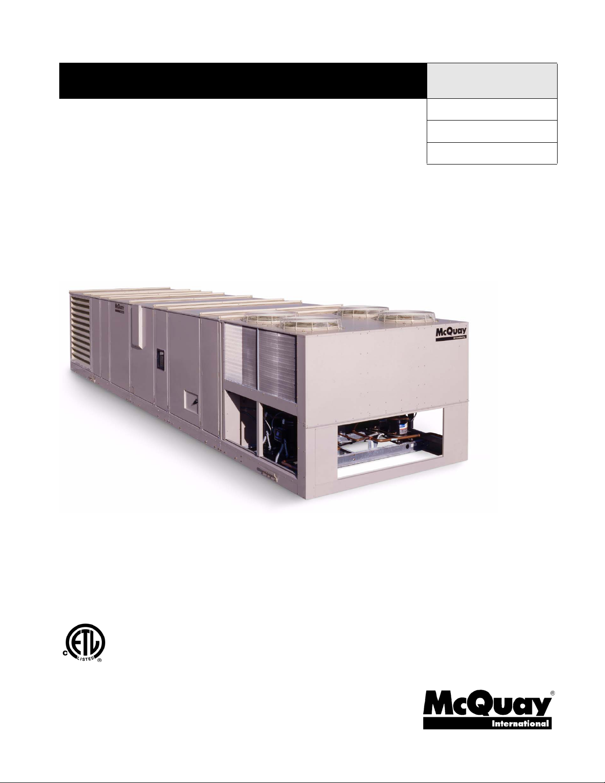
RoofPak™ Singlezone Roof Mounted
Heating and Cooling Units
RPS/RDT/RFS/RCS 015-135C
Group: Applied Systems
Part Number: IM 738
Date: June 2006
US
© 2006 McQuay International
Page 2

Contents
Introduction . . . . . . . . . . . . . . . . . . . . . . . . . . . . . . . . . . . . . . . 3
Unit Nameplate . . . . . . . . . . . . . . . . . . . . . . . . . . . . . . . . . . . . 3
Compressor Nameplate . . . . . . . . . . . . . . . . . . . . . . . . . . . . . 3
Gas Burner Nameplate . . . . . . . . . . . . . . . . . . . . . . . . . . . . . . 3
Hazard Identification Information . . . . . . . . . . . . . . . . . . . . . . . 3
Unit Description . . . . . . . . . . . . . . . . . . . . . . . . . . . . . . . . . . . . 5
Typical Component Locations . . . . . . . . . . . . . . . . . . . . . . . . . 6
Condenser Fan Arrangement . . . . . . . . . . . . . . . . . . . . . . . . . 8
Refrigeration Piping . . . . . . . . . . . . . . . . . . . . . . . . . . . . . . . . . 9
Control Locations . . . . . . . . . . . . . . . . . . . . . . . . . . . . . . . . . 12
Control Panel . . . . . . . . . . . . . . . . . . . . . . . . . . . . . . . . . . . . . 14
Controls, Settings, and Functions . . . . . . . . . . . . . . . . . . . . . 22
Mechanical Installation . . . . . . . . . . . . . . . . . . . . . . . . . . . 25
Unit Clearances . . . . . . . . . . . . . . . . . . . . . . . . . . . . . . . . . . . 25
Ventilation Clearance . . . . . . . . . . . . . . . . . . . . . . . . . . . . . . 25
Overhead Clearance . . . . . . . . . . . . . . . . . . . . . . . . . . . . . . . 26
IBC Seismic Compliant Units . . . . . . . . . . . . . . . . . . . . . . . . 30
Roof Curb Arrangement . . . . . . . . . . . . . . . . . . . . . . . . . . . . 30
Post and Rail Arrangement . . . . . . . . . . . . . . . . . . . . . . . . . . 32
Post and Rail Mounting . . . . . . . . . . . . . . . . . . . . . . . . . . . . . 34
Rigging and Handling . . . . . . . . . . . . . . . . . . . . . . . . . . . . . . 34
Reassembly of Split Units . . . . . . . . . . . . . . . . . . . . . . . . . . . 38
RPS/RDT Factory Split at Condensing Unit . . . . . . . . . . . . . 42
RFS/RCS Permanent Split Systems . . . . . . . . . . . . . . . . . . . 47
Unit Piping . . . . . . . . . . . . . . . . . . . . . . . . . . . . . . . . . . . . . . . 52
Steam Coil Piping . . . . . . . . . . . . . . . . . . . . . . . . . . . . . . . . . 54
Steam Piping Recommendations . . . . . . . . . . . . . . . . . . . . . 54
Steam Trap Recommendations . . . . . . . . . . . . . . . . . . . . . . . 55
Damper Assemblies . . . . . . . . . . . . . . . . . . . . . . . . . . . . . . . 56
Cabinet Weather Protection . . . . . . . . . . . . . . . . . . . . . . . . . 58
Installing Ductwork . . . . . . . . . . . . . . . . . . . . . . . . . . . . . . . . 58
Installing Duct Static Pressure Sensor Taps . . . . . . . . . . . . . 59
Installing Building Static Pressure Sensor Taps . . . . . . . . . . 60
Electrical Installation . . . . . . . . . . . . . . . . . . . . . . . . . . . . . 61
Field Power Wiring . . . . . . . . . . . . . . . . . . . . . . . . . . . . . . . . 61
Field Control Wiring . . . . . . . . . . . . . . . . . . . . . . . . . . . . . . . . 64
Preparing Unit for Operation . . . . . . . . . . . . . . . . . . . . . 65
Spring Isolated Fans . . . . . . . . . . . . . . . . . . . . . . . . . . . . . . . 65
Relief Damper Tie-Down . . . . . . . . . . . . . . . . . . . . . . . . . . . . 66
Adjusting Scroll Dampers . . . . . . . . . . . . . . . . . . . . . . . . . . . 66
Adjusting Supply Fan Thrust Restraints . . . . . . . . . . . . . . . . 66
Sequences of Operation . . . . . . . . . . . . . . . . . . . . . . . . . . 67
Power-up . . . . . . . . . . . . . . . . . . . . . . . . . . . . . . . . . . . . . . . . 67
Fan Operation . . . . . . . . . . . . . . . . . . . . . . . . . . . . . . . . . . . . 67
Economizer Operation . . . . . . . . . . . . . . . . . . . . . . . . . . . . . . 68
Mechanical Cooling Operation . . . . . . . . . . . . . . . . . . . . . . . 68
Heating . . . . . . . . . . . . . . . . . . . . . . . . . . . . . . . . . . . . . . . . . 70
Wiring Diagrams . . . . . . . . . . . . . . . . . . . . . . . . . . . . . . . . . . 71
Unit Options . . . . . . . . . . . . . . . . . . . . . . . . . . . . . . . . . . . . . . 97
Enthalpy Control . . . . . . . . . . . . . . . . . . . . . . . . . . . . . . . . . . 97
Hot Gas Bypass . . . . . . . . . . . . . . . . . . . . . . . . . . . . . . . . . . 98
SpeedTrol™ (N/A Unit Sizes 015C to 030C) . . . . . . . . . . . . 99
External Time Clock . . . . . . . . . . . . . . . . . . . . . . . . . . . . . . 100
Smoke and Fire Protection . . . . . . . . . . . . . . . . . . . . . . . . . 100
Smoke Detectors . . . . . . . . . . . . . . . . . . . . . . . . . . . . . . . . . 100
Freeze Protection . . . . . . . . . . . . . . . . . . . . . . . . . . . . . . . . . 100
Entering Fan Temperature Sensor . . . . . . . . . . . . . . . . . . . 102
Duct High Pressure Limit . . . . . . . . . . . . . . . . . . . . . . . . . . . 102
MicroTech II™ Remote User Interface (UI) . . . . . . . . . . . . . 102
Variable Frequency Drive Operation . . . . . . . . . . . . . . . . . . 104
Convenience Receptacle/Section Lights . . . . . . . . . . . . . . . 104
DesignFlow™ Outdoor Air Damper Option . . . . . . . . . . . . . 104
Propeller Exhaust Fan Option . . . . . . . . . . . . . . . . . . . . . . . 107
Exhaust Fan On/Off Control . . . . . . . . . . . . . . . . . . . . . . . . . 109
Ultraviolet Lights Option . . . . . . . . . . . . . . . . . . . . . . . . . . . . 110
Ultraviolet Light Operation . . . . . . . . . . . . . . . . . . . . . . . . . . 111
Check, Test, and Start Procedures . . . . . . . . . . . . . . 112
Servicing Control Panel Components . . . . . . . . . . . . . . . . . 112
Before Start-up . . . . . . . . . . . . . . . . . . . . . . . . . . . . . . . . . . . 112
Power Up . . . . . . . . . . . . . . . . . . . . . . . . . . . . . . . . . . . . . . . 113
Fan Start-up . . . . . . . . . . . . . . . . . . . . . . . . . . . . . . . . . . . . . 113
Economizer Start-up . . . . . . . . . . . . . . . . . . . . . . . . . . . . . . 113
Compressor Startup . . . . . . . . . . . . . . . . . . . . . . . . . . . . . . . 114
Scroll Compressor Rotational Direction (sizes 15 to 105) . . 114
Oil Pressure (sizes 115 to 135C only) . . . . . . . . . . . . . . . . . 115
Heating System Start-up . . . . . . . . . . . . . . . . . . . . . . . . . . . 116
Air Balancing . . . . . . . . . . . . . . . . . . . . . . . . . . . . . . . . . . . . 117
Sheave Alignment . . . . . . . . . . . . . . . . . . . . . . . . . . . . . . . . 118
Drive Belt Adjustment . . . . . . . . . . . . . . . . . . . . . . . . . . . . . 118
Mounting and Adjusting Motor Sheaves . . . . . . . . . . . . . . . 119
Final Control Settings . . . . . . . . . . . . . . . . . . . . . . . . . . . 122
Maintenance . . . . . . . . . . . . . . . . . . . . . . . . . . . . . . . . . . . . . 126
Servicing Control Panel Components . . . . . . . . . . . . . . . . . 126
Planned Maintenance . . . . . . . . . . . . . . . . . . . . . . . . . . . . . 126
Unit Storage . . . . . . . . . . . . . . . . . . . . . . . . . . . . . . . . . . . . . 126
Gas Furnace . . . . . . . . . . . . . . . . . . . . . . . . . . . . . . . . . . . . 127
Bearing Lubrication . . . . . . . . . . . . . . . . . . . . . . . . . . . . . . . 127
Setscrews . . . . . . . . . . . . . . . . . . . . . . . . . . . . . . . . . . . . . . 129
Supply Fan Wheel-to-Funnel Alignment . . . . . . . . . . . . . . . 130
Refrigerant Leaks . . . . . . . . . . . . . . . . . . . . . . . . . . . . . . . . . 131
Refrigerant Charge . . . . . . . . . . . . . . . . . . . . . . . . . . . . . . . 131
Servicing Refrigerant Sensors or Switches . . . . . . . . . . . . . 131
Winterizing Water Coils . . . . . . . . . . . . . . . . . . . . . . . . . . . . 131
Control Panel Components . . . . . . . . . . . . . . . . . . . . . . . . . 132
Replacement Parts List . . . . . . . . . . . . . . . . . . . . . . . . . . 135
Service and Warranty Procedure . . . . . . . . . . . . . . . . 137
Scroll Compressor (sizes 15 to 105C) . . . . . . . . . . . . . . . . . 137
Reciprocating Compressors (sizes 115 to 135C) . . . . . . . . 137
All Compressors . . . . . . . . . . . . . . . . . . . . . . . . . . . . . . . . . . 138
Limited Product Warranty (North America) . . . . . . 139
Exceptions . . . . . . . . . . . . . . . . . . . . . . . . . . . . . . . . . . . . . . 139
Assistance . . . . . . . . . . . . . . . . . . . . . . . . . . . . . . . . . . . . . . 139
Sole Remedy . . . . . . . . . . . . . . . . . . . . . . . . . . . . . . . . . . . . 139
Rooftop Equipment Warranty Regist. Form . . . . . 140
Page 3
Introduction
Introduction
This manual provides general information about the “C”
vintage McQuay RoofPak applied rooftop unit, models RPS,
RDT, RFS, and RCS. In addition to an overall description of
the unit, it includes mechanical and electrical installation
procedures, commissioning procedures, sequence of operation
information, and maintenance instructions. For further
information on the optional forced draft gas-fired furnace,
refer to Bulletin No. IM 684 or IM 685.
The MicroTech II applied rooftop unit controller is available
on “C” vintage applied rooftop units. For a detailed description
of the MicroTech II components, input/output configurations,
field wiring options, requirements, and service procedures, see
IM 696-3. For operation and information on using and
programming the MicroTech II unit controller, refer to the
appropriate operation manual (see Table 1).
For a description of operation and information on using the
keypad to view data and set parameters, refer to the
appropriate program-specific operation manual (see Table 1).
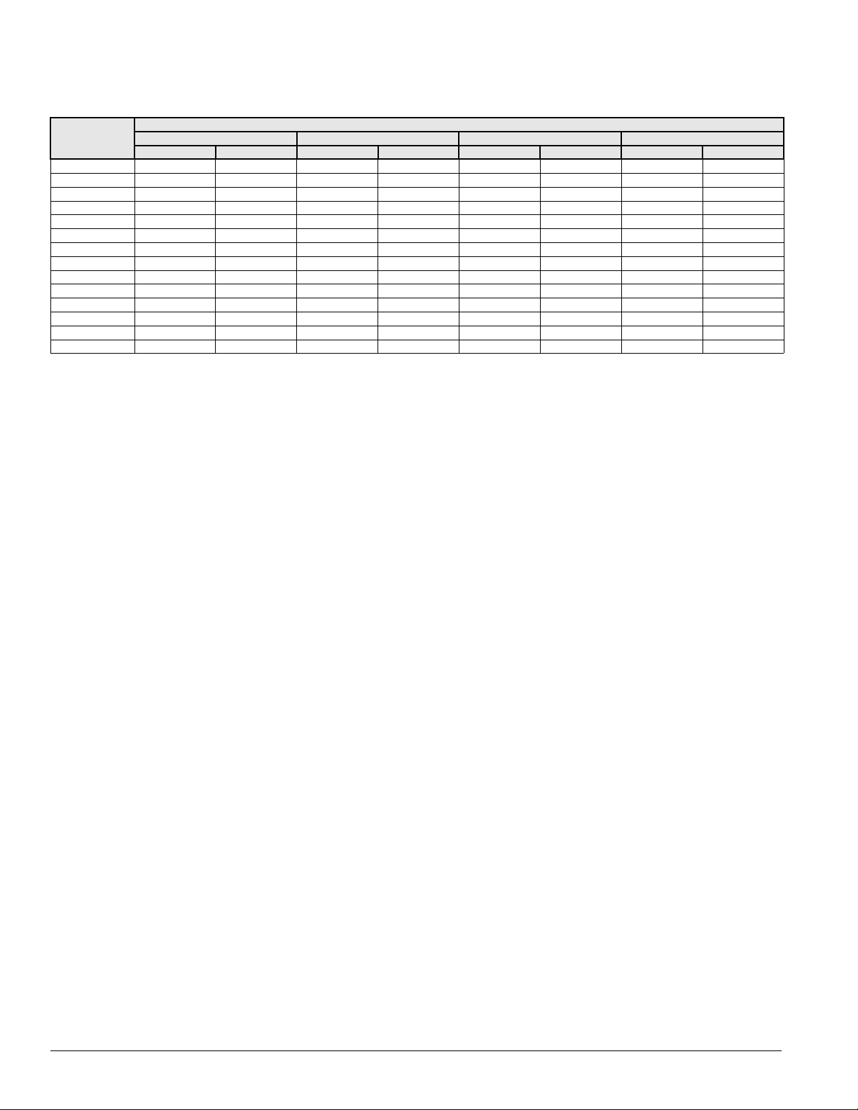
Table 1: Program specific rooftop unit operation literature
Rooftop unit control configuration
VFDs Vendor IM manuals
Discharge Air Control (VAV or CAV) OM 137-2
Space Comfort Control
(CAV-Zone temperature control)
Operation manual bulletin
number
OM 138-2
Unit Nameplate
The unit nameplate is located on the outside lower right corner
of the main control box door. It includes the unit model
number, serial number, unit part number, electrical
characteristics, and refrigerant charge.
On units that utilize the tandem compressor design, each
compressor includes an individual nameplate along with a
nameplate identifying the tandem compressors.
Gas Burner Nameplate
On units that include gas heat, the nameplate is located on the
lower right corner of the main control box door. It includes the
burner model number, minimum/maximum input, maximum
temperature rise, and minimum cfm.
On units that utilize the tandem scroll compressor design, each
compressor includes an individual nameplate along with a
nameplate identifying the tandem compressors.
On units that utilize the tandem reciprocating design, each
compressor includes an individual nameplate.
Hazard Identification Information
WARNING
Warnings indicate potentially hazardous situations, which can
result in property damage, severe personal injury, or death if
not avoided.
CAUTION
Cautions indicate potentially hazardous situations, which can
result in personal injury or equipment damage if not avoided.
Compressor Nameplate
On units with a single compressor on each circuit, the
compressor includes one compressor nameplate.
McQuay IM 738-2 3
Page 4

Introduction
Figure 1: Nomenclature
R P S – 030 C S E
RoofPak
Unit configuration
P = Heating, mechanical cooling
F = Heating, future mechanical cooling
C = Condensing section only
D = Draw through cooling
Blow through cooling = S
Draw through cooling = T
Nominal capacity (tons)
RPS, RFS, RCS, RDT: 015, 018, 020, 025, 030, 036,
040, 045, 050, 060, 070, 075, 080, 090, 105, 115, 125, 135
Heat medium
A = Natural gas
E = Electric
S = Steam
W = Hot water
Y = None (cooling only)
Cooling coil size
S=Standard (low airflow)
L =Large (high airflow)
Design vintage
4 McQuay IM 738-2
Page 5
Unit Description
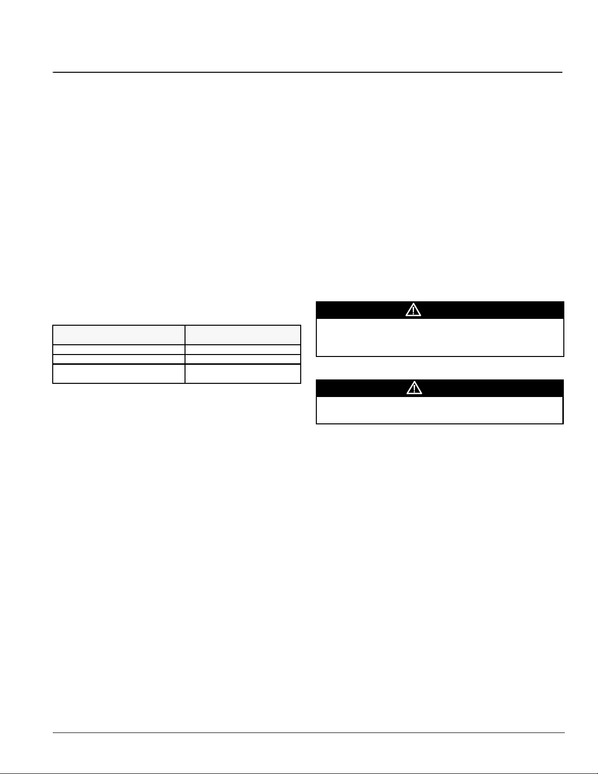
Figure 2: RPS/RDT/RFS/RCS unit
Introduction
R P S / R D T
R F S
R C S
McQuay IM 738-2 5
Page 6
Introduction
Typical Component Locations
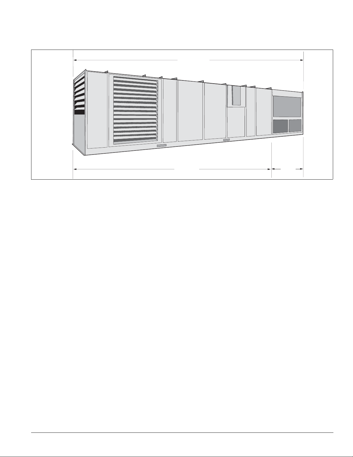
Figure 2 shows an RPS/RDT/RFS/RCS unit. Figure 3 shows a
typical RPS unit with the locations of the major components.
Figure 3: Typical component locations—RPS units
Top View
Outside and return air dampersa
Side View
Exhaust
hood
Bottom return air opening
Filter section
Supply air fan
Figure 4 on page 7 shows a typical RDT unit with the locations
of the major components.
These figures are for general information only. See the
project’s certified submittals for actual specific dimensions
and locations.
Bottom discharge air opening
Power and control entrances
Evaporator coil
Discharge plenum
(main control panel)
Optional back
return opening
Return air
Return airReturn air
fan
Outside air
louvers
Heat section (natural gas, oil,
steam, hot water, electric
Air cooled condenser
6 McQuay IM 738-2
Page 7
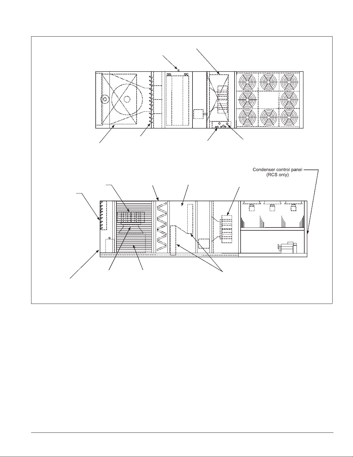
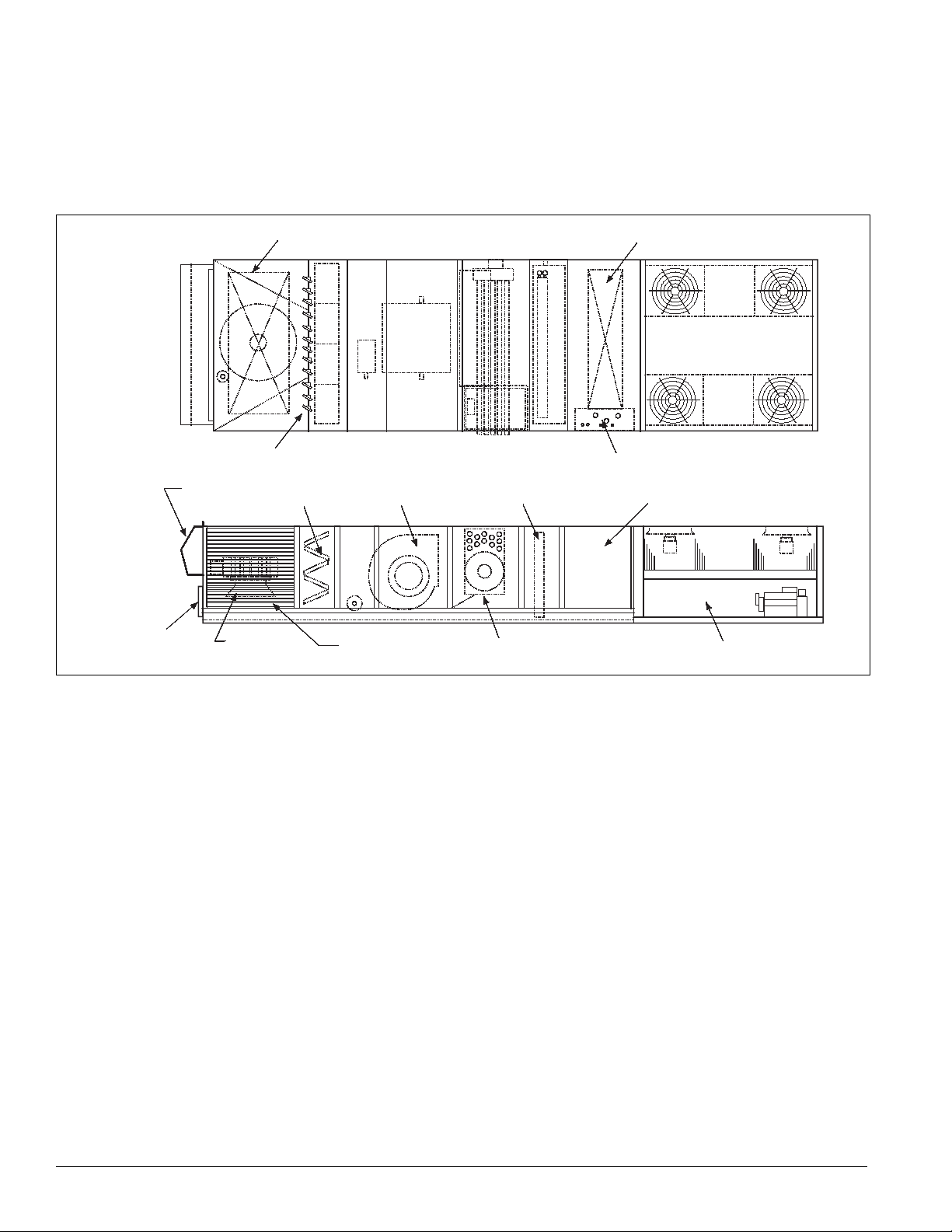
Figure 4: Component locations—RDT units
Top View
Introduction
Bottom supply air opening
1.50 MPT drain
Bottom return opening
Side View
Return air plenum
Exhaust dampers
Optional back return
air opening
Return air fan
Optional outside &
return air dampers
Filter section
Outside air louvers
(both sides)
Control entrances 7/8" dia K.O.
DX coil section
Evaporator coils
Power entrances 3" dia K.O.
Supply fan section
McQuay IM 738-2 7
Page 8
Introduction
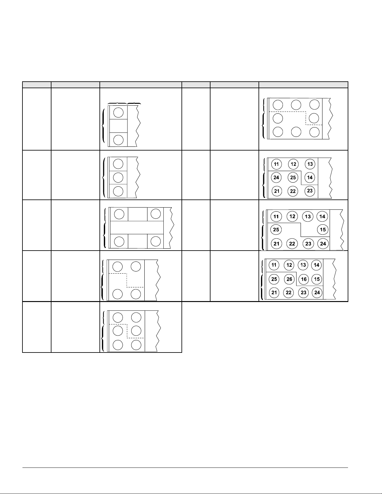
Condenser Fan Arrangement
Table 2 shows the condenser fan numbering conventions and
locations for each unit size.
Table 2: Condenser fan arrangement
Unit size Refrigerant circuit Arrangement Unit size Refrigerant circuit Arrangement
COND
015C
018C
020C
1 or 2
12
11
AHU
075C
080C
090C
1
2
11
24
21
12
22
13
14
23
025C
030C 1 or 2
036C
040C
045C
050C
060C
070C
1
2
1
2
1
2
11
13
12
11
21
11
23
21
21
11
12
22
12
13
22
12
22
1
105C
2
1
115 C
2
1
125C
135C
2
8 McQuay IM 738-2
Page 9
Introduction
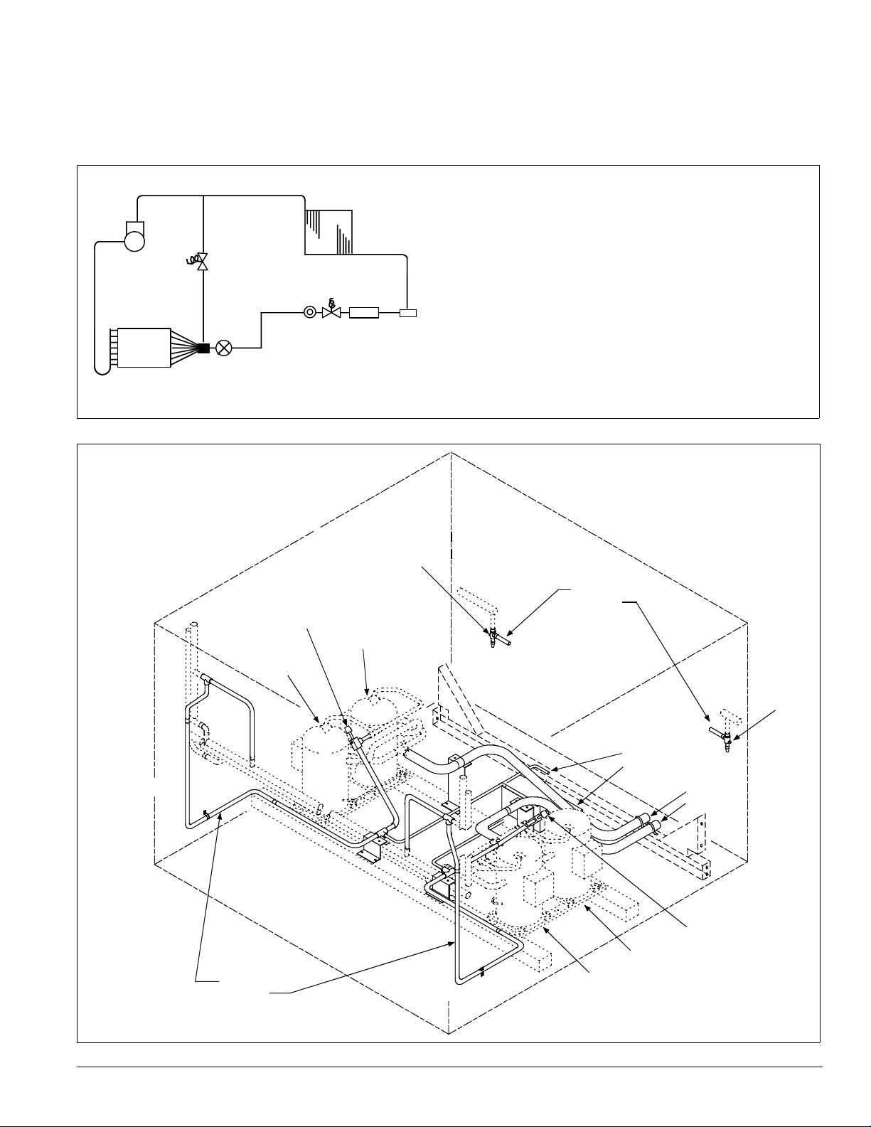
Refrigeration Piping
This section presents the unit refrigeration piping diagrams for
the various available configurations.
Figure 5: Circuit schematic
A - Compressor (1, 2, or 3 per circuit)†
B - Discharge line †
B
A
M
C
J
N
L
K
G
H
I
F
E
D
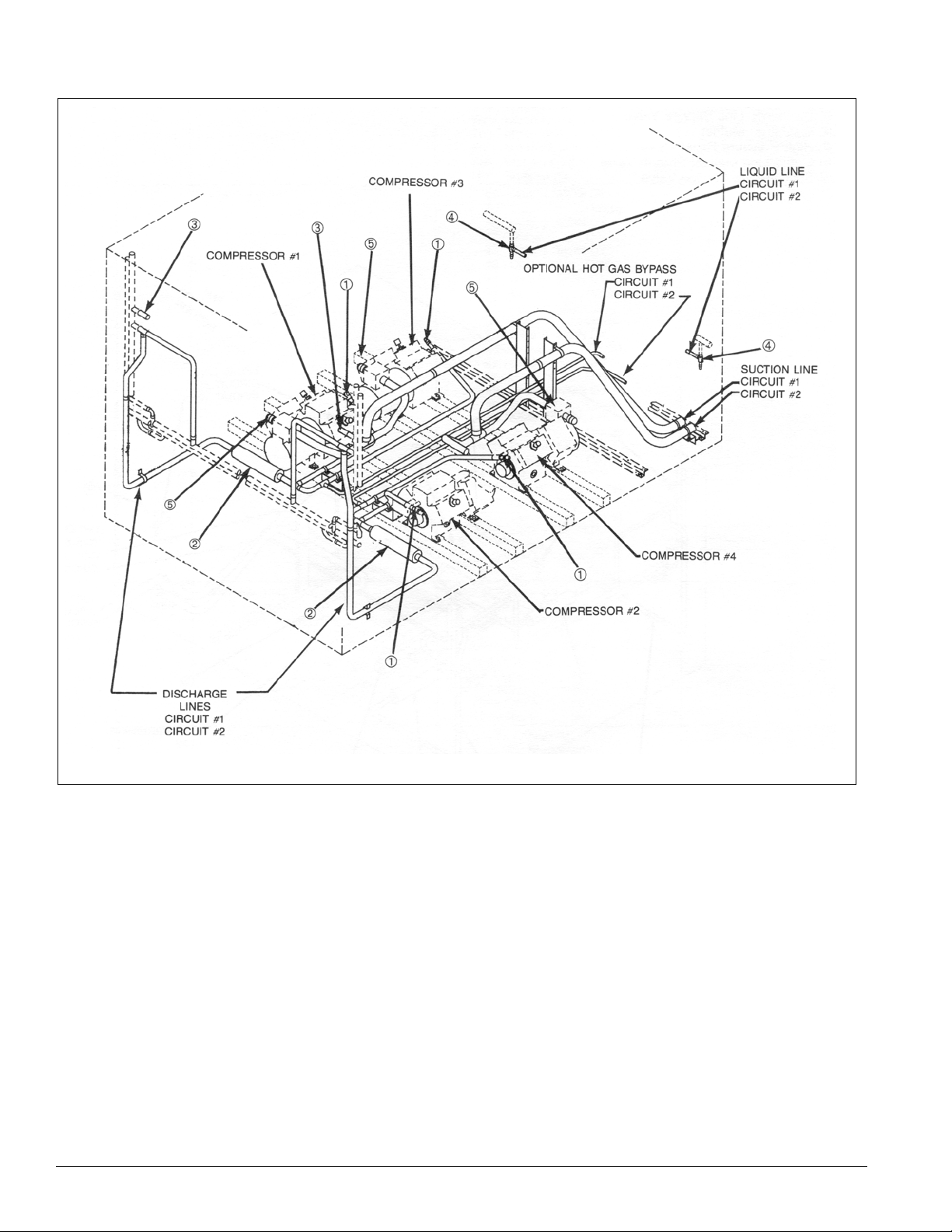
Figure 6: Condenser piping, scroll compressors, one to three compressors per circuit are provided (015 to 105C)
Legend
1 - Discharge shut-off valve—Circuit #1
2 - Liquid shut-off valve—Circuit #1
3 - Liquid shut-off valve—Circuit #2
4 - Discharge shut-off valve—Circuit #2
C - Condenser coil †
D - Evaporator coil*
E - Manual shutoff valve†
F - Filter-drier*
G - Liquid line solenoid valve*
H - Sightglass*
I - Liquid line*†
J - Suction line
K - Thermal expansion valve*
L - Distributor*
M - Hot gas bypass and solenoid valve (optional)*†
N - Hot gas bypass lines (optional)* †
*Supplied on RFS units
†Supplied on RCS units
Compressor #1
Discharge lines
Circuit #1
Circuit #2
1
Compressor #3
2
Liquid lines
Circuit #1
Circuit #2
3
Compressor #4
Compressor #2
Optional
hot gas
bypass
lines
Circuit #1
Circuit #2
Suction
lines
Circuit #1
Circuit #2
4
McQuay IM 738-2 9
Page 10
Introduction
Figure 7: Condenser piping, four reciprocating compressors (115 to 135C)
Legend
1 - Discharge Line Service Valve
2 - Discharge Muffler
3 - High Pressure Relief Valve
4 - Liquid Line Manual Shut-off Valve
5 - Suction Line Service Valve
10 McQuay IM 738-2
Page 11
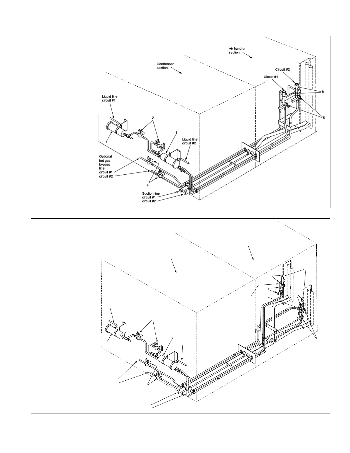
Figure 8: Air handler piping (flat DX)
circu
Legend
1 - Filter-drier
2 - Liquid line solenoid valve
3 - Sightglass
4 - Hot gas bypass and solenoid valve (optional)
5 - Thermostatic expansion valve
6 - Distributor
Introduction
Figure 9: Air handler piping (staggered DX)
Legend
1 - Filter-drier
2 - Liquid line solenoid valve
3 - Sightglass
4 - Hot gas bypass and solenoid valve (optional)
5 - Thermostatic expansion valve
6 - Distributor
Liquid line
circuit #1
1
Optional
hot gas
bypass
line
circuit #1
circuit #2
Air handler
section
Condenser
section
Circuit #1
6
5
Circuit #2
2
1
Liquid line
circuit #2
4
6
5
Suction line
circuit #1
it #2
McQuay IM 738-2 11
Page 12
Introduction
Control Locations
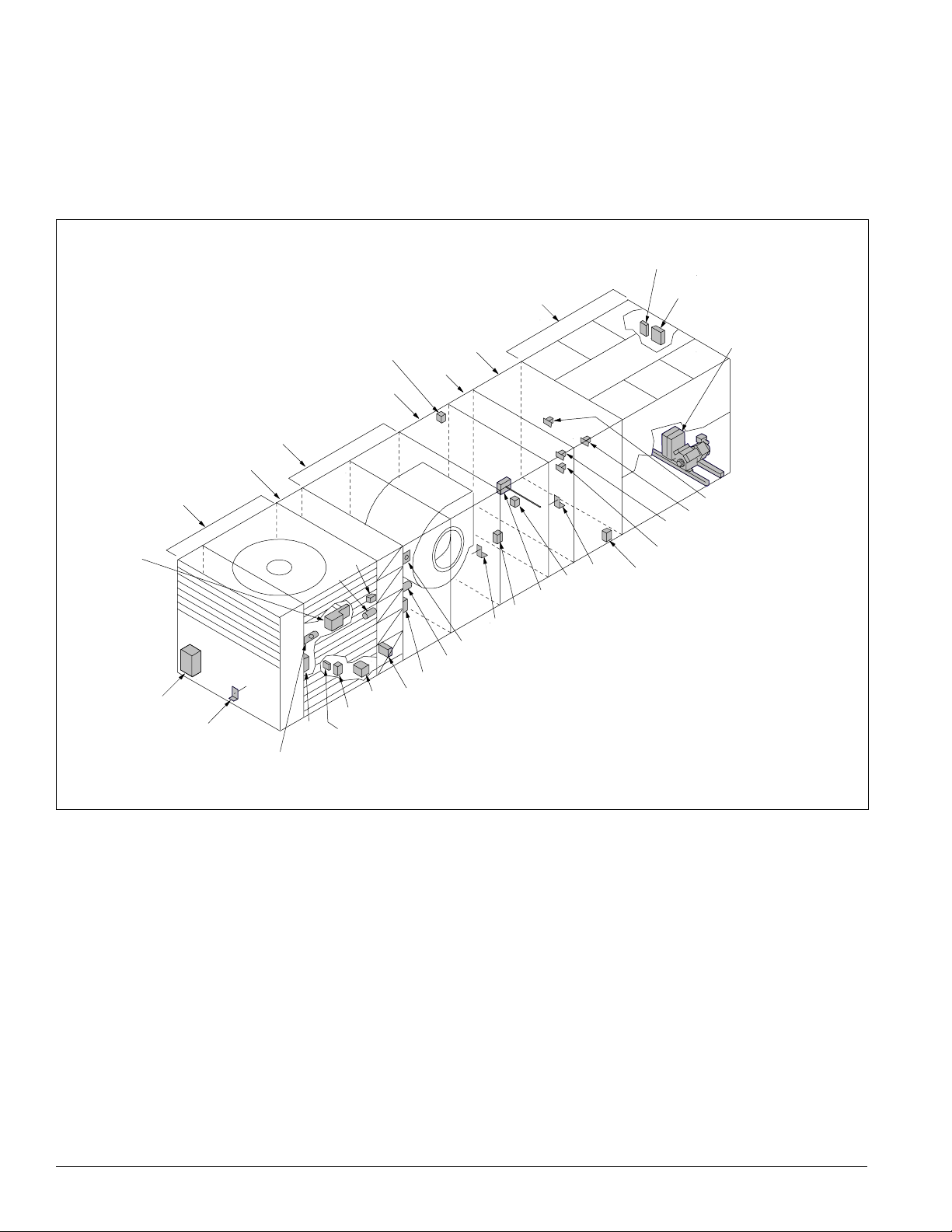
Figure 10 (RPS Units) and Figure 11 on page 13 (RDT Units)
show the locations of the various control components mounted
throughout the units. See “Control Panel” on page 14 for the
locations of control components mounted in control panels.
Figure 10: Control locations—RPS units
FS1
SD2
(optional)
Return air
economizer
C19
RAT
Filter
section
Supply
fan
section
LT11
(opt io nal )
OAT
S11,
REC11
(optional)
Heat
section
OAE
ACT3
ACT6 (optional)
RAE (optional)
section
LT10
S10, REC10
PC5
Additional information is included in Table 3 on page 22 and
the wiring diagram legend, which is included in “Wiring
Diagrams” on page 71.Components mounted in the blowthrough section are located in the same position within the
draw-through section.
SC11, 12
(optional)
C11, 12
(optional)
SV1
SV5 (optional)
SV6 (optional)
ACT5 (optional)
HP1-2, HP3-4 (optional)
LP1-2
HTR1-2, HTR3-4 (optional)
SV2
Disc harge
DX
HL22
plenum
section
EFT
(optional)
(optional)
(optional)
Condensor
section
SD1
PC7
DAT
(optional)
VM1
(optional)
12 McQuay IM 738-2
Page 13
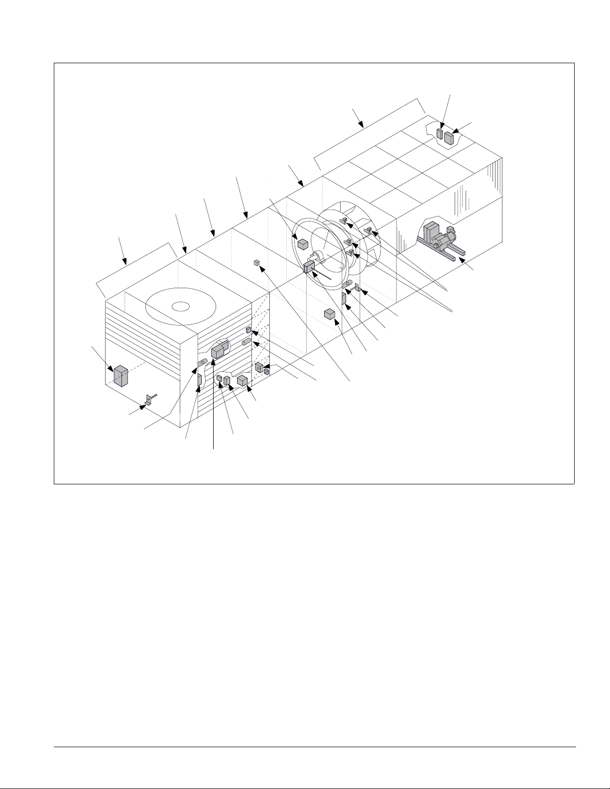
Figure 11: Control locations—RDT units
DX
section
Filter
section
Economizer
return air
Heat
section
Supply fan
discharge
plenum
section
C9
Condenser
section
SC11, 21
(optional)
SV1, 2
Introduction
C11, 21
(optional)
HP1-2, LP1-2
HTR1-2, U1/U2
HP3-4 (optional)
HTR3-4 (optional)
C19, 20
(optional)
RAT
LT11 (optional)
S11, REC11
SD2
(optional)
(optional)
RAE
(optional)
ACT3
ACT6
PC5
OAE
OAT
VM1
(optional)
FS1
(optional)
DAT
LT10 (optional)
S10, REC10 (optional)
SD1 (optional)
SV5, 6 (optional)
McQuay IM 738-2 13
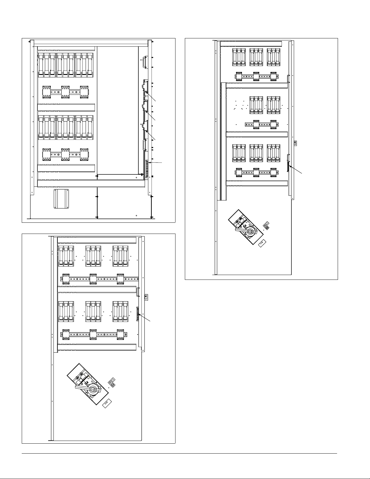
Page 14
Introduction
Control Panel
The unit control panels and their locations are shown in the
following figures. These figures show a typical unit
Figure 12: Control panel locations
Prop exhaust
(optional)
not shown)
(
VFDs, line reactors, and
manual bypass
(optional)
Electric heat
control panel
(optional)
configuration. Specific unit configurations may differ slightly
from these figures depending on the particular unit options.
Supply fan
section
Condenser
section
Main control panel
14 McQuay IM 738-2
Page 15
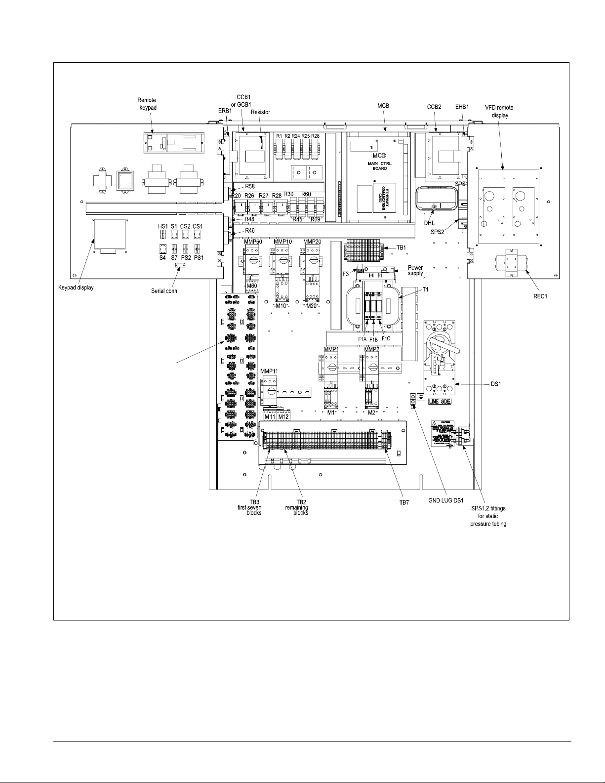
Figure 13: Typical main control panel, 015 to 040, 460 volt
Introduction
See separate
detail, page 17.
McQuay IM 738-2 15
Page 16
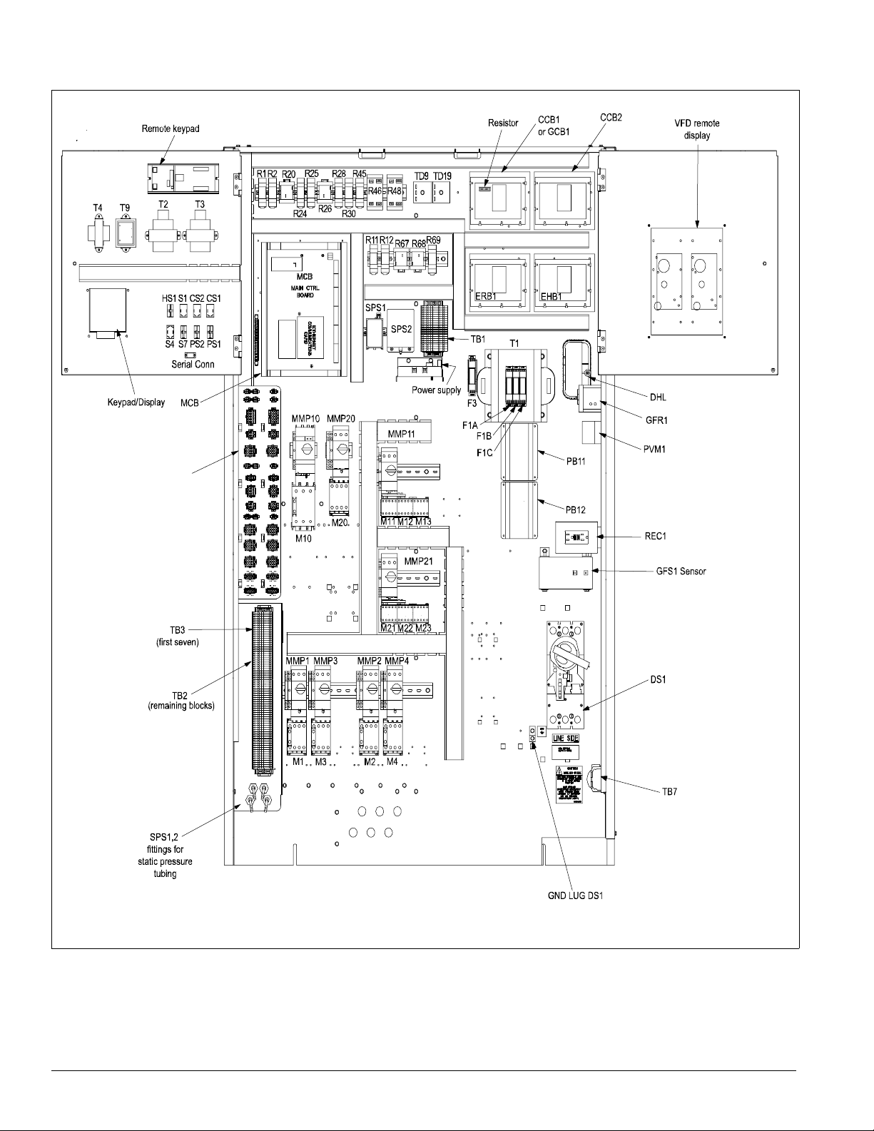
Introduction
Figure 14: Typical main control panel, 045 to 075, 460 volt
See separate
detail, page 17.
16 McQuay IM 738-2
Page 17
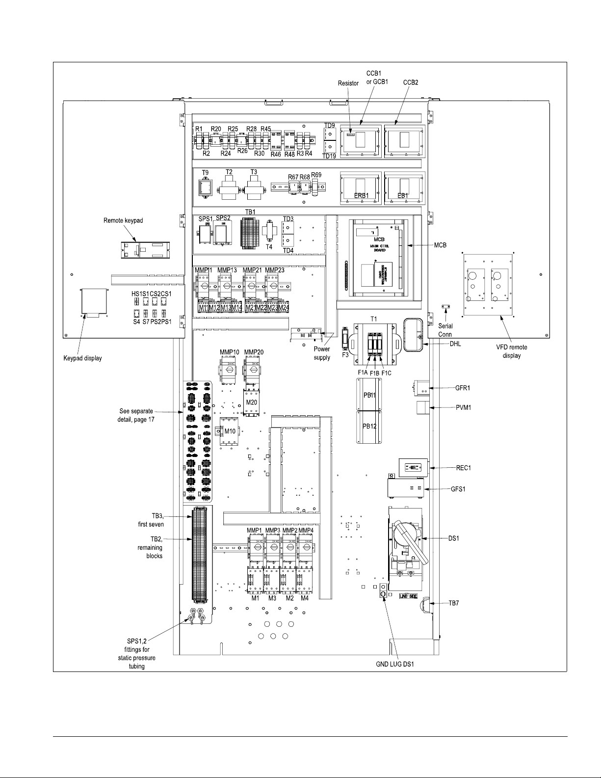
Figure 15: Typical main control panel, 080 to 135, 460 volt
Introduction
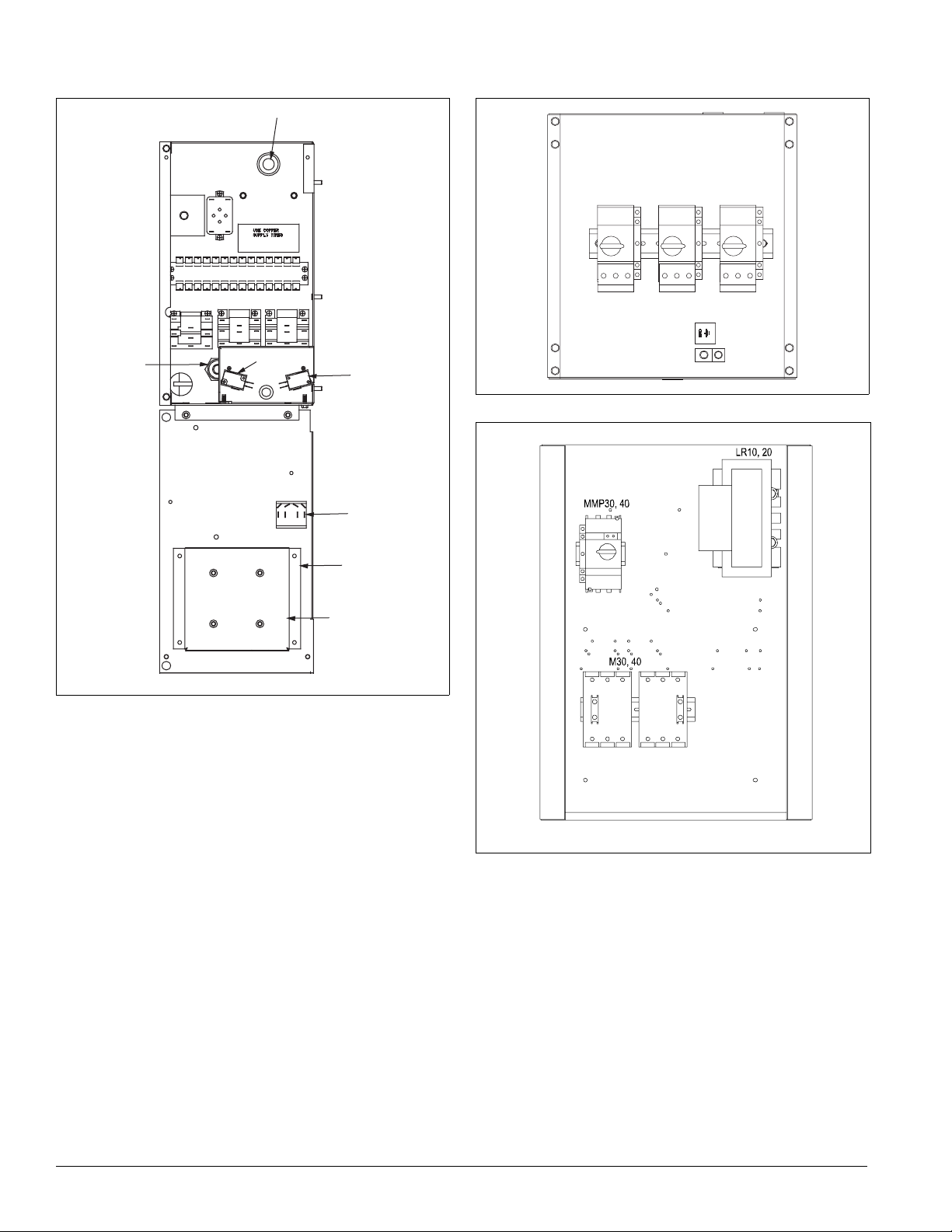
Figure 16:
McQuay IM 738-2 17
Page 18
Introduction
e
A
Figure 17: Typical gas heat panel, 1000 MBH Figure 18: Typical propeller exhaust panel, 3 fans, 460 volt
IT
R22
TD10
R20
S
R23 R21
LS2
LS1
Figure 19: VFD bypass panel, 40 HP, 460 volt)
S3
FSG
FSG Tim
18 McQuay IM 738-2
Page 19
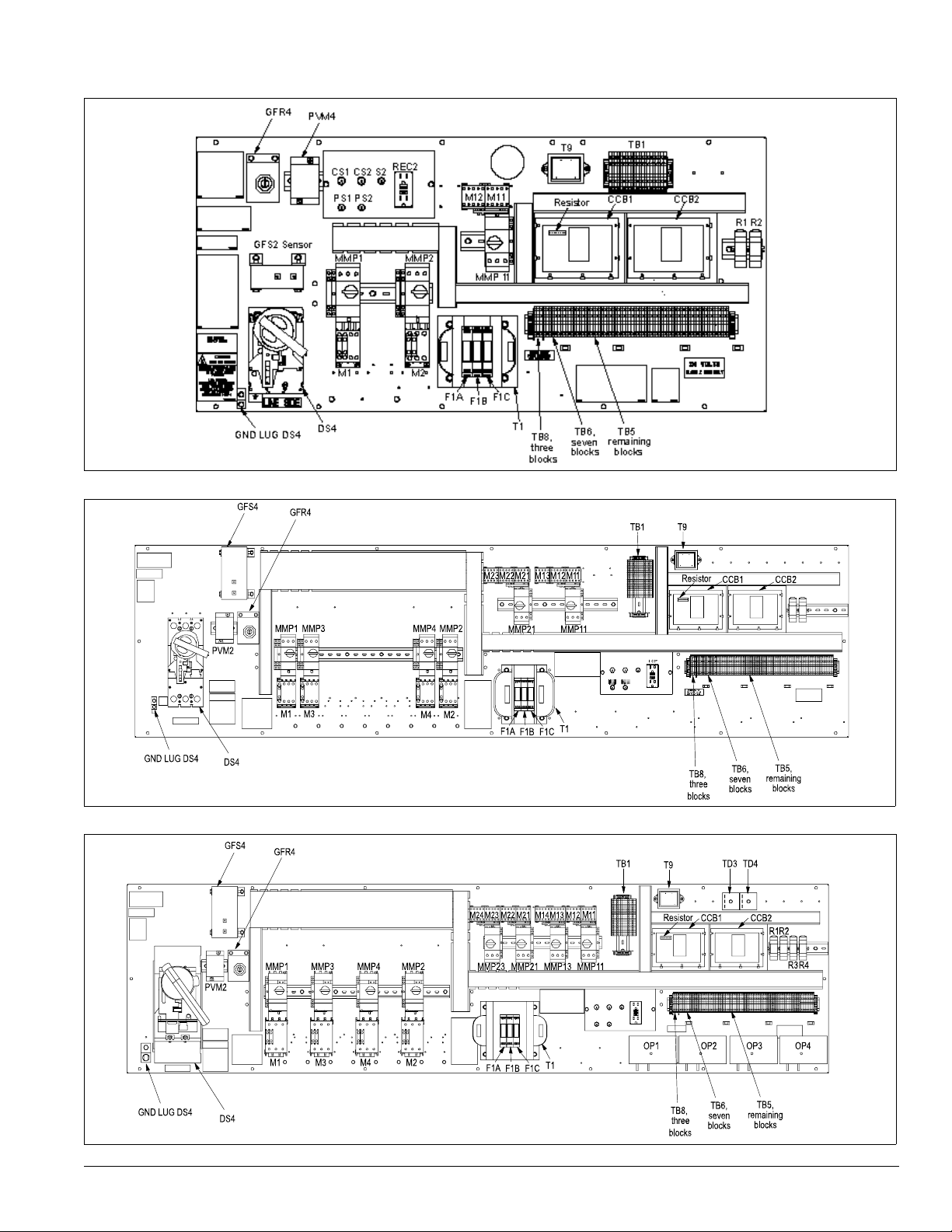
Figure 20: RCS control panel with MicroTech II, 015 to 040C
Figure 21: RCS control panel with MicroTech II, RPS 045 to 075C
Introduction
Figure 22: RCS control panel with MicroTech II, RPS 080 to 135C
McQuay IM 738-2 19
Page 20
Introduction
Figure 23: Electric heat panel, sizes 15 to 40C
FB33 FB32 FB31
M33 M32 M31
FB43 FB42 FB41
M41 M42 M41
SR2
SR3
SR1
TB11
Figure 25: Electric heat panel, sizes 80 to 135
FB31FB32FB33
M31M32M33
FB34FB44
M34M44
FB41FB42FB43
M41M42M43
H53
TB11
PB3
Figure 24: Electric heat panel, sizes 45 to 75C
FB31FB32FB33
M31M32M33
FB41FB42FB43
M42
M41M43
GLG3
DS3
H53
TB11
GLG3
DS3
20 McQuay IM 738-2
Page 21
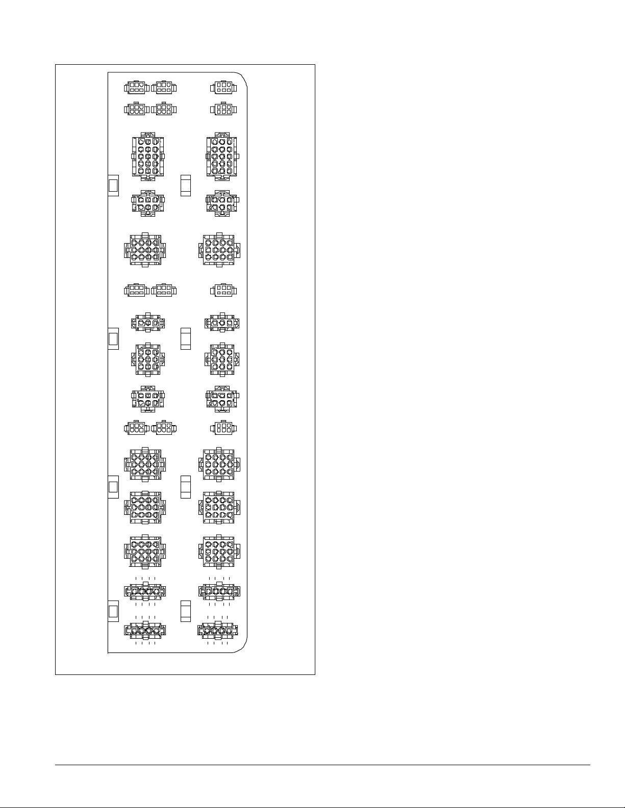
Figure 26: Harness plug connector detail
RATS OATSDATS
FP1 OPEN1EPTS
AFD10 AFD20
SV12 SV56
ACT3 OPEN2
OAE PC7PC5
Introduction
HL22 OPEN3
GSHT1 GSHT2
SD1 SD2
DFRH DFLH OPEN4
COMP1 COMP2
COMP3 COMP4
COMP6COMP5
LT11LT1 0
LT OP1 LT OP2
McQuay IM 738-2 21
Page 22

Introduction
Controls, Settings, and Functions
Table 3 below lists all of the unit control devices and
associated information.
Table 3: Controls, settings, and functions
Symb
ol
CS1 &
2
DAT
DHL
EFT
FP1, 2
FS1
HP1,
2,
3 & 4
LP1, 2
MCB
MP1–
6
OAE
OAT
PC5
Description Function
Switch (toggle),
refrigerant circuit
Discharge air
temperature
sensor
Duct high limit
switch
Entering fan air
temperature
sensor
Evaporator frost
protection
Freezestat
High pressure
control
Low pressure
control
Main control board Processes input information
Compressor motor
protector
Enthalpy control
(electromechanical)
Enthalpy control
(electronic)
Outside air
temperature
sensor
Dirty filter switch Senses filter pressure drop
Shuts off compressor control
circuits manually
Senses discharge air
temperature
Prevents excessive VAV duct
pressures; shuts off fan
Senses entering fan air
temperature
Senses low refrigerant
temperature
Shuts off fans, opens heating
valve, and closes outdoor
damper if low air temperature
at coil is detected
Stops compressor when
refrigerant discharge
pressure is too high
Stops compressor when
suction pressure is too low
(used for pumpdown)
Senses motor winding
temperature, shuts off
compressor on high
temperature.
Notes:
1.Unit size 018C compressors
include internal motor
protector.
2.Unit sizes 020C–036C,
circuit #1 compressors
include internal motor
protector (refer to unit wiring
diagram).
Returns outside air dampers
to minimum position when
enthalpy is too high
Returns outside air dampers
to minimum position when
outside air enthalpy is higher
than return air empalthy (use
RAE)
Senses outside air
temperature
Rese
t
N/A
N/A
Auto
N/A
N/A
Auto
Manu
al
(relay
latche
d)
Auto Compressor
N/A
Auto
at
3400
ohms
Auto
Auto
N/A N/A N/A
Auto
Location Setting Range Differential Part no.
Main control
panel
Discharge air
section
Main control
panel
Inlet of supply
fan
Return bends
of evaporative
coil
Heating
section
Compressor
Main control
box
Compressor
junction box
Economizer
section
Economizer
section
First filter
section
N/A N/A N/A 01355000
N/A N/A
3.5" w.c
(871.8 Pa)
N/A N/A
Opens at
30°F
Closes at
45°F
38°F (3°C)
or as
required
See page
131.
See page
131.
N/A N/A N/A
9 K–18 K
ohms
“B” or as
required
Fully CW
past “D”
(when used
with RAE)
As required
0.05–5.0" wc
(12.5–1245.4
Pa)
N/A N/A
35°F–45°F
(2°C–7°C)
N/A
N/A
700 ohms cold N/A
A–D
A–D N/A
.05-5" wc
(12.5–1245.4
Pa)
.05" wc
(12.5 Pa),
fixed
12°F (7°C),
fixed
100 psi
(689 kPa)
25 psi
(172 kPa)
Temperature:
3.5°F (2°C)
Humidity:
5% fixed
.05" wc
(12.5 Pa)
06000470
5
06549380
1
06000470
5
07250190
1
06583000
1
04735612
0
047356111
06000610
1
04469150
9
03070670
2
04926220
1
06000470
5
06549380
1
22 McQuay IM 738-2
Page 23
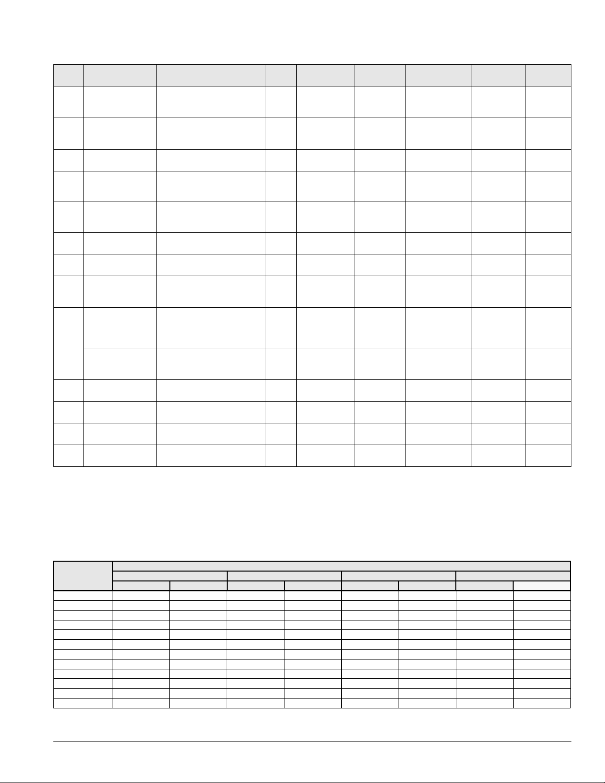
Table 3: Controls, settings, and functions (continued)
Symb
ol
PC6
PC7
PS1,
2
RAE
RAT
SD1
SD2
SPS1
SPS2
SV1,
2
SV5,
6
S1
S7
Description Function
Dirty filter switch Senses filter pressure drop
Airflow proving
switch
Pumpdown switch Used to manually pump down
Return air enthalpy
sensor
Return air
temperature
sensor
Smoke detector,
supply air
Smoke detector,
return air
Static pressure
sensor duct #1
Static pressure
sensor duct #2
Static pressure
sensor: building
(space) pressure
Solenoid valve
(liquid line)
Solenoid valve
(hot gas bypass)
System switch
ON-OFF-AUTO
switch
Senses supply fan pressure
to prove airflow
compressor
Used to compare return air
enthalpy to outside air
enthalpy (used with OAE)
Senses return air temperature
Initiates unit shutdown if
smoke is detected
Initiates unit shutdown if
smoke is detected
Converts static pressure
signals to voltage signals
Converts static pressure
signals to voltage signals and
sends them to MicroTech II
controller
Converts static pressure
signals to voltage signals.
Closes liquid line for
pumpdown
Closes hot gas bypass line for
pump-down
Shuts off entire control circuit
(except crankcase heaters)
Used to manually switch unit
Rese
Auto
Auto
N/A
N/A
N/A
ManualDischarge air
ManualReturn air
N/A
N/A
N/A
N/A
N/A
N/A
N/A
Location Setting Range Differential Part no.
t
Final filter
section
Supply fan
section
Condenser
control box
Economizer
section
Return air
section
section
section
Main control
box
Main control
box
Main control
box
Condenser
section
Condenser
section
Main control
box
Main control
box
Introduction
As required
.10" wc (25
Pa)
N/A N/A N/A 01355000
N/A N/A N/A
N/A N/A
N/A N/A N/A 04925001
N/A N/A N/A 04925001
N/A
N/A
N/A
N/A N/A N/A
N/A N/A N/A 111011001
N/A N/A N/A
N/A N/A N/A
.05-5" wc
(12.5–1245.4
Pa)
.03-1.40" wc
(7.5–348 Pa)
0–5" wc
(0–1245.4 Pa)
1–6 V (dc) out
0–5" wc
(0–1245.4 Pa)
1–6 V (dc) out
-025–0.25" wc
(-62.3–62.3 Pa)
1–5 V (dc) out
.05" wc
(12.5 Pa)
.03" wc
(7.5 Pa),
fixed
N/A
N/A
N/A
06549380
06001580
04926220
06000470
04954500
04954500
04954500
00135500
1
1
2
5
7
7
6
See parts
catalog
0
FanTrol
The FanTrol, provided on all units, is a method of head
pressure control that automatically cycles the condenser fans
in response to ambient air temperature. This feature maintains
head pressure and allows the unit to run at low ambient air
temperatures.
RPS/RDT and RCS units have two independent refrigerant
circuits with one to four condenser fans being controlled
independently by the ambient air temperature of each circuit.
Table 4: R-22 FanTrol setpoints in °F with MicroTech II controls
RPS RCS
RDT RPR
015 to 020C0 5 60 5 ————
025 to 030C0 5 65 5 ————
0360 5 70 5 ————
045 to 045C0 5 65 5 ————
0500 5 60 5 ————
0600 5255705——
0700 5405705——
075 to 090C 0 5 65 5 75 5 0 5
1050505585705
1150505555755
1250 5655355805
1350 5555255655
Setpoint Differential Setpoint Differential Setpoint Differential Setpoint Differential
B05 B06 B07 B08
McQuay IM 738-2 23
Degrees Farenheit
Page 24
Introduction
Table 5: R-407C FanTrol setpoints in °F with MicroTech II controls
RPS, RCS, RDT
Setpoint Differential Setpoint Differential Setpoint Differential Setpoint Differential
015 0 5 60 5
018 to 020C0505————
025 to 036C0 5 65 5 ————
040 0 5 60 6
0450 5 55 5 ————
050 0 5 50 5 — —
0600 5155705——
0700 5305705——
0750 5655755 0 5
080 to 090C 0 5 65 5 75 5 0 5
1050505525705
1150505455755
1250 5555305805
1350 5455205655
B05 B06 B07 B08
Degrees Farenheit
24 McQuay IM 738-2
Page 25
Mechanical Installation
Mechanical Installation
Note – The installation of this equipment shall be in accordance
with the regulations of authorities having jurisdiction and
all applicable codes. It is the responsibility of the installer
to determine and follow the applicable codes. Low head
pressure may lead to poor, erratic refrigerant feed control
at the thermostatic expansion valve. The units have
automatic control of the condenser fans which should
provide adequate head pressure control down to 50°F
(10°C) provided the unit is not exposed to windy
conditions. The system designer is responsible for
assuring the condensing section is not exposed to
excessive wind or air recirculation.
CAUTION
Sharp edges on sheet metal and fasteners can cause personal
injury.
This equipment must be installed, operated, and serviced only
by an experienced installation company and fully trained
personnel.
Receiving Inspection
When the equipment is received, all items should be carefully
checked against the bill of lading to be sure all crates and
Figure 27: Service clearances
72"
(1829 mm)
cartons have been received. If the unit has become dirty
during shipment (winter road chemicals are of particular
concern), clean it when received.
All units should be inspected carefully for damage when
received. Report all shipping damage to the carrier and file a
claim. In most cases, equipment ships F.O.B. factory and
claims for freight damage should be filed by the consignee.
Before unloading the unit, check the unit nameplate to make
sure the voltage complies with the power supply available.
Unit Clearances
Service Clearance
Allow an approximate service clearance as indicated in
Figure 27. Also, McQuay recommends providing a roof
walkway to the rooftop unit as well as along two sides of the
unit that provide access to most controls and serviceable
components.
60"
(1524 mm)
Roof walkway
To roof
access
location
A
60"
(1524 mm)
BC
DE
96"
(2438 mm)
Varies with unit arrangement
Refer to certified drawing & note.
Ventilation Clearance
Below are minimum ventilation clearance recommendations.
The system designer must consider each application and
provide adequate ventilation. If this is not done, the unit will
not perform properly.
Unit(s) surrounded by a screen or a fence:
C
F
60"
(1524 mm)
Legend:
A = Return air section
B = Filter section
C = Cooling section
D = Cooling/supply fan section
E = Heat section
F = Discharge plenum section
1
The bottom of the screen or fence should be at least 1 ft.
(305 mm) above the roof surface.
2 The distance between the unit and a screen or fence should
be as described in Figure 27.
3 The distance between any two units within a screen or
fence should be at least 120" (3048 mm).
McQuay IM 738-2 25
Page 26
Mechanical Installation
Unit(s) surrounded by solid walls:
1 If there are walls on one or two adjacent sides of the unit,
the walls may be any height. If there are walls on more than
two adjacent sides of the unit, the walls should not be
higher than the unit.
2 The distance between the unit and the wall should be at
least 96" (2438 mm) on all sides of the unit.
3 The distance between any two units within the walls should
be at least 120" (3048 mm).
Do not locate outside air intakes near exhaust vents or other
sources of contaminated air.
If the unit is installed where windy conditions are common,
install wind screens around the unit, maintaining the
clearances specified (see Figure 28). This is particularly
important to prevent blowing snow from entering the outside
air intake and to maintain adequate head pressure control when
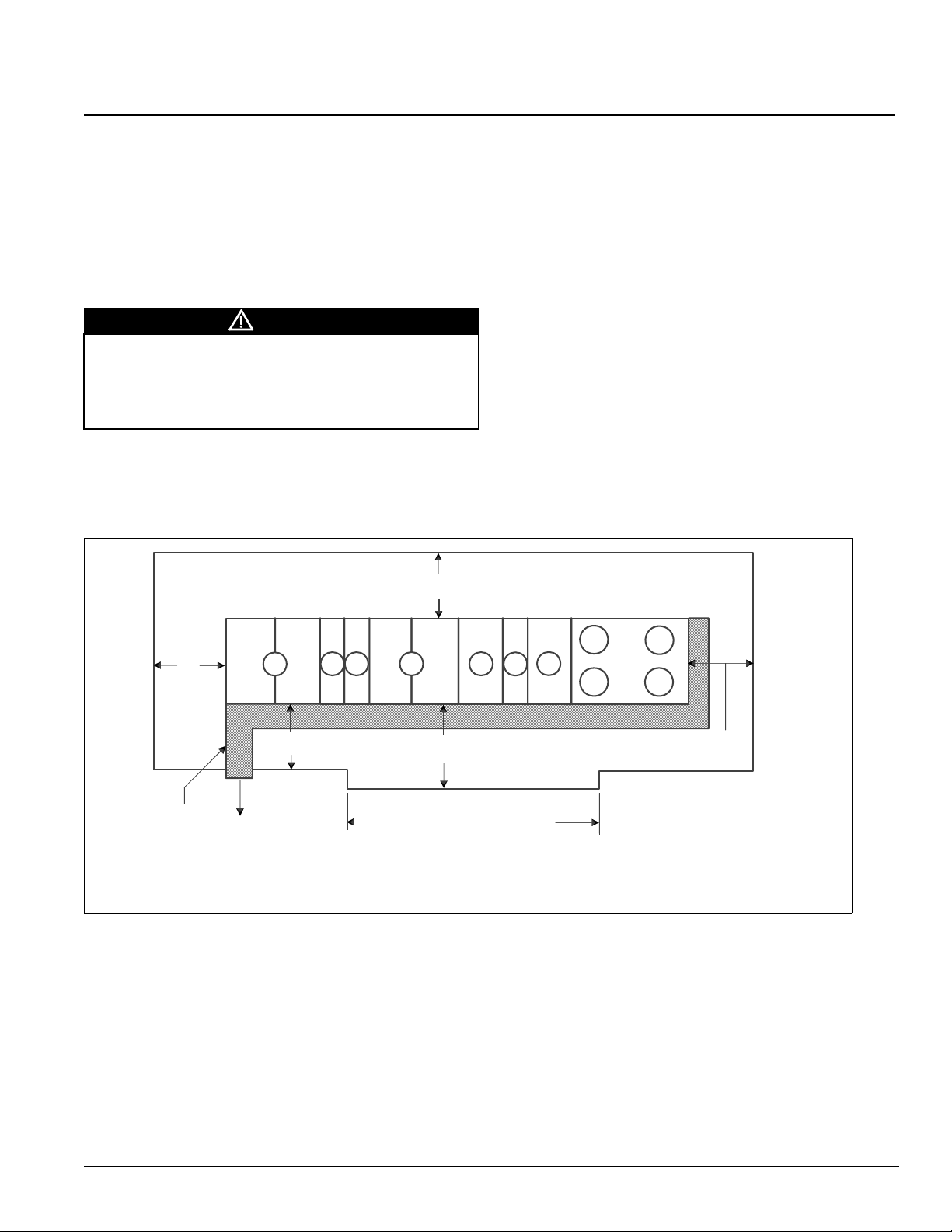
Figure 28: Overhead clearance
Overhead
canopy
mechanical cooling is required at low outdoor air
temperatures.
Overhead Clearance
1 Unit(s) surrounded by screens or solid walls must have no
overhead obstructions over any part of the unit.
2 The area above the condenser must be installed
unobstructed to allow vertical air discharge.
3 The following restrictions must be observed for overhead
obstructions above the air handler section (see Figure 28):
a There must be no overhead obstructions above the
furnace flue, or within 9" (229 mm) of the flue box.
b Overhead obstructions must be no less than 96"
(2438 mm) above the top of the unit.
c There must be no overhead obstructions in the areas
above the outside air and exhaust dampers that are
farther than 24" (610 mm) from the side of the unit.
24" (610 mm)
maximum
96" (2438 mm)
minimum,
top of unit to
permanent
overhead
obstruction
9" (229 mm)
minimum to flue box,
typical all sides
Flue box
24" (610 mm)
maximum
26 McQuay IM 738-2
Page 27
Mechanical Installation
Roof Curb Assembly and Installation
Locate the roof curb and unit on a portion of the roof that can
support the weight of the unit. The unit must be supported to
prevent bending or twisting of the machine.
If building construction allows sound and vibration into the
occupied space, locate the unit over a non-critical area. It is
the responsibility of the system designer to make adequate
provisions for noise and vibration in the occupied space.
WARNING
Mold can cause personal injury. Some materials such as
gypsum wall board can promote mold growth when damp.
Such materials must be protected from moisture that can enter
units during maintenance or normal operation.
Install the curb and unit level to allow the condensate drain to
flow properly and allow service access doors to open and close
without binding.
Figure 29: RCS roof curb assembly
6 "
" Z Z "
6 "
1 . U n i t B a s e
B
A
A
2 . G a l v a n i z e d C u r b
3 . G a l v a n i z e d C u i r b C o v e r
4 . 2 x 4 N a i l e r S t r i p
5 . R i g i d I n s u l a t i o
6 "
6 . C a n t S t r i p ( n o t f u r n i s h e d )
7 . F l a s h i n g ( n o t f u r n i s h e d )
8 . C u r b G a s k e t i n g
9 . I n s u
G a l v a n i z e d C u r b ( n o t f u r n i s h e d )
1 0 . R o o f i n g M a t e r i a l ( n o t f u r n i s h e d )
B
A
A
n ( n o t f u r n i s h e d )
l a t i o n b e t w e e n
Integral supply and return air duct flanges are provided with
the RPS/RFS roof curb, allowing connection of duct work to
the curb before the unit is set. The gasketed top surface of the
duct flanges seals against the unit when it is set on the curb.
These flanges must not support the total weight of the duct
work. See “Installing Ductwork” on page 58for details on duct
connections. It is critical that the condensate drain side of the
unit be no higher than the opposite side.
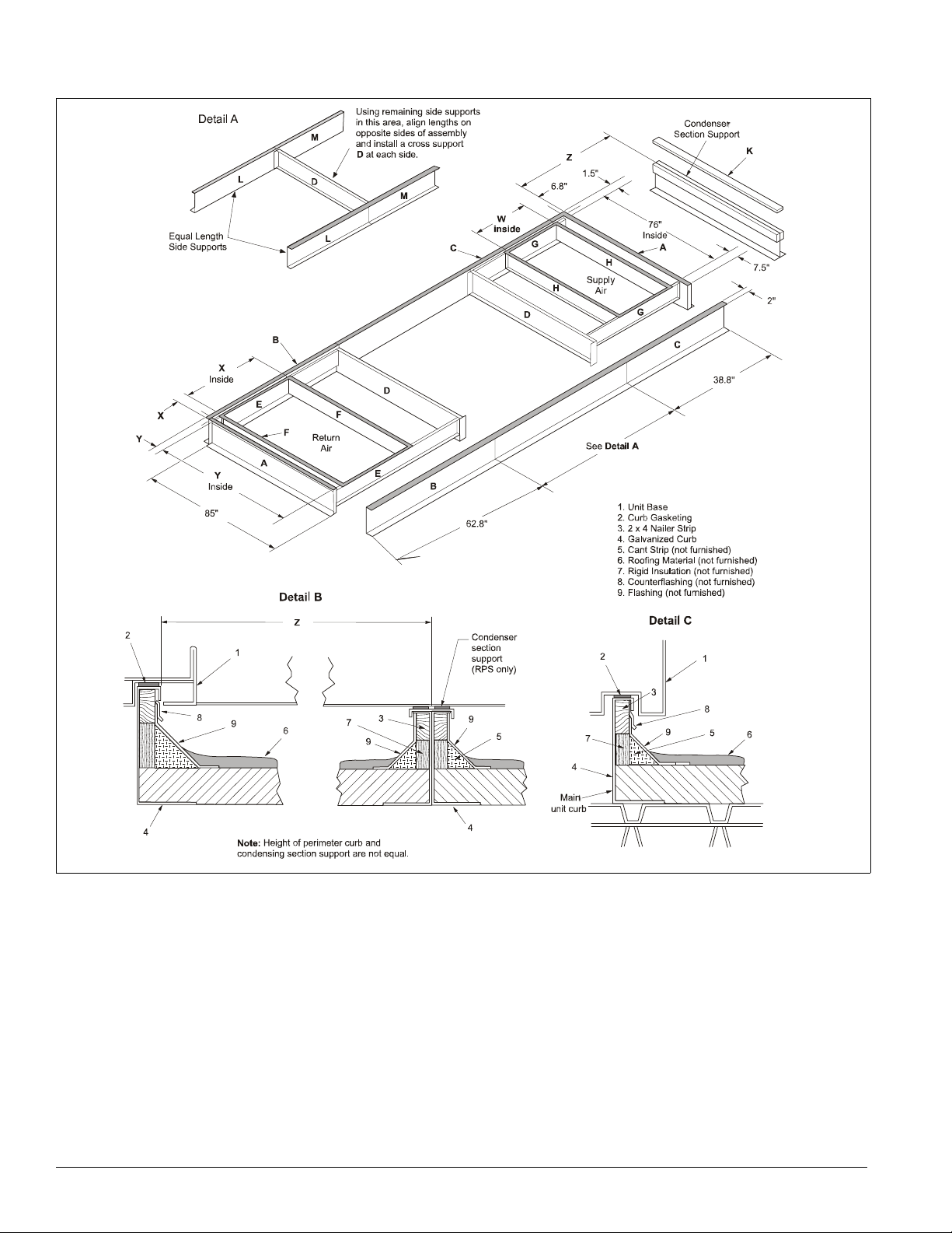
Assembly of a typical RPS/RDT roof curb is shown in
Figure 30 on page 28. Parts A through K are common to all
units having bottom return openings. Depending on the unit
length, Parts L and M may be included with the roof curb kit to
create the correct overall curb length.
Figure 29 shows the assembly of the RCS roof curb.
RCS unit size
015C–030C 31.0 787
6 "
D e t a i l C
1
5
6
8
4
7
9
3
4
5
1 0
2
036C & 040C 94.0 2057
045C–060C 62.0 1575
070C–105C 100.0 2540
115C–135C 120.0 3048
in. mm
“ZZ”
RCS Assembly instructions
1 Set curbing parts “A” (Figure 29) in place making sure that
the orientation complies with the assembly instructions.
Check alignment of all mating bolt holes.
2 Bolt curbing parts together using fasteners provided.
3 Curb must be level from side to side and over its length.
4 Weld curbing in place. Caulk all seams watertight and
insulate between channels.
5 Flash curbing into roof as shown in Detail C.
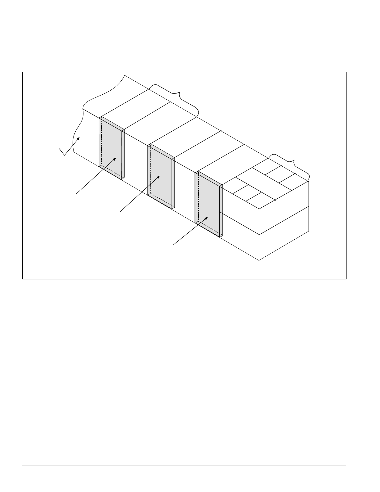
RPS/RDT Assembly instructions
1 Set curbing parts A through K per dimensions shown over
roof opening or on a level surface (see Figure 30 on
page 28). Note location of return and supply air openings.
2 If applicable, set other curbing parts (D, L, M, etc.) in place
making sure that the orientation complies with the
assembly instructions (see Detail A). Check alignment of
3 Bolt curbing parts together using fasteners provided.
Tighten all bolts finger tight.
4 Square entire curbing assembly and securely tighten all
bolts.
5 Position curb assembly over roof openings. Curb must be
level from side to side and over its length. Check that top
surface of the curb is flat with no bowing or sagging.
6 Weld curbing in place. Caulk all seams watertight. Remove
backing from 0.25" (6 mm) thick × 1.50" (38 mm) wide
gasketing and apply to surfaces shown by cross-hatching.
7 Flash curbing into roof as shown in Detail B.
8 Parts E and F are not required on units with no return shaft
within the curb perimeter.
9 Parts G and H are not required on units with no supply shaft
within the curb perimeter.
10 Be sure that electrical connections are coordinated (see
Figure 36).
all mating bolt holes.
McQuay IM 738-2 27
Page 28
Mechanical Installation
Figure 30: RPS/RFS roof curb assembly
28 McQuay IM 738-2
Page 29

Mechanical Installation
Table 6: Roof curb assembly dimensions
Unit size Fan
None 24.0 610 82.0 2083 6.8 173 1.5 38 015C–030C 45.9 1165 20.0 508
015–040C
045C–075C All units 38.0 965 87.0 2210 8.8 222 3.5 89 105C—135C 113 2870 46.0 1168
80C–135C All units 62.0 1575 87.0 2210 8.8 222 3.5 89
Note: These dimensions do not apply to units with energy recovery wheels.
(2) 15” FC 24.0 610 82.0 2083 6.8 173 1.5 38
30" AF 30.0 762 76.0 1930 6.8 173 4.5 114 045C–075C 77.0 1956 28.0 712
40" AF 36.0 914 78.0 1981 14.8 376 3.5 89 80C–90C 113 2870 38.0 965
“X” “Y” “XX” “YY”
in mm in mm in mm in mm in mm in mm
Unit size
036C and
040C
“Z” “W”
94.0 2388 20.0 508
McQuay IM 738-2 29
Page 30
Mechanical Installation
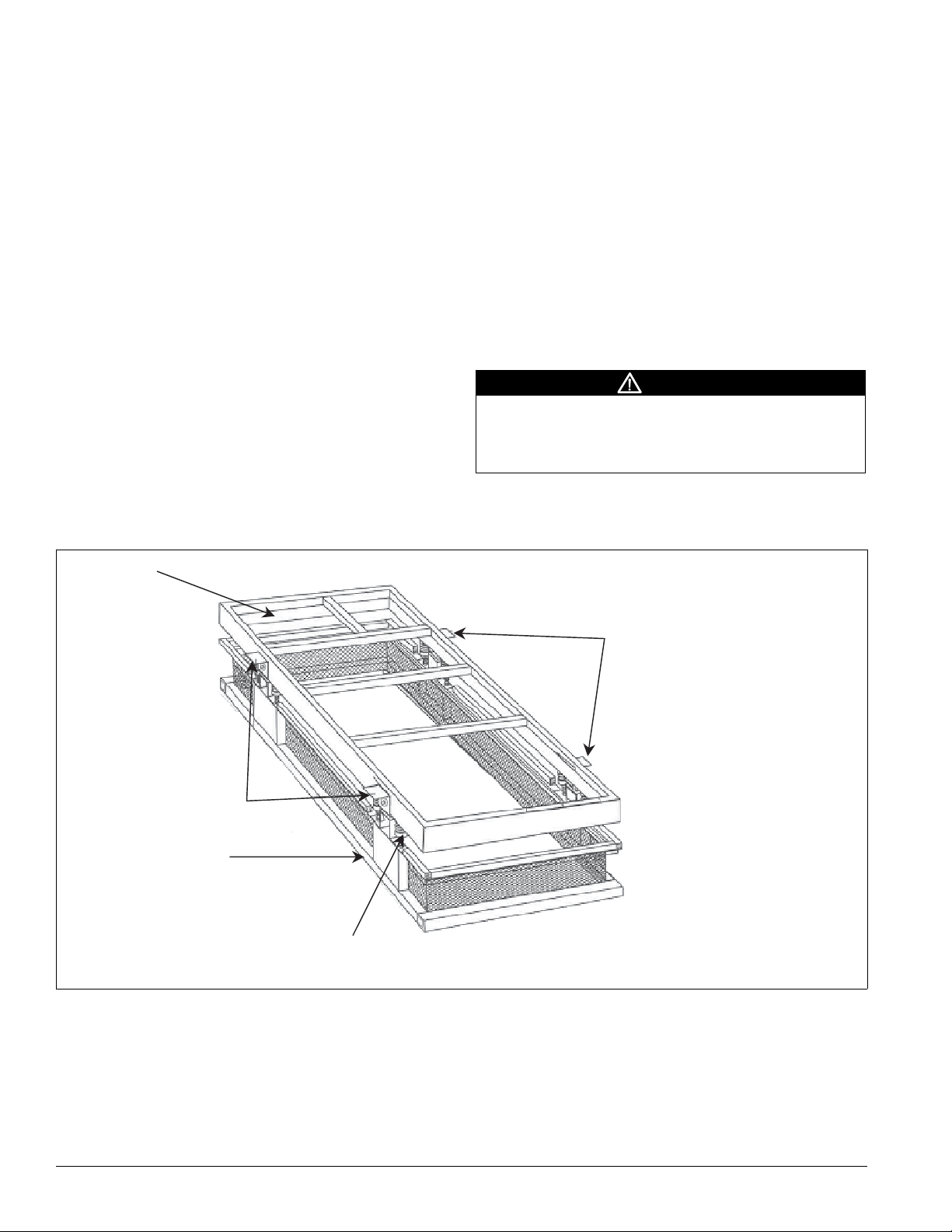
IBC Seismic Compliant Units
It is important to follow these installation instructions for all
IBC Seismic compliant McQuay Rooftop units.
IBC Seismic compliant McQuay Rooftop units can be
mounted to either a roof curb or a post and rail setup. If using a
roof curb, it must be specifically designed for seismic restraint
and be IBC seismic compliant (spring isolated or non-isolated
type seismic roof curbs are available). Typical construction of
a seismic rated roof curb is from structural steel framing and
contains seismic hold down brackets for attachment of the
rooftop unit (see Figure 31). Post and rail arrangements rated
for seismic applications are also available (spring isolated or
non-isolated).
IMPORTANT: An acceptable IBC seismic installation
provides a direct positive attachment to both the building
structure and the roof mounted equipment.
Refer to the roof curb manufacturer’s submittal drawings for
actual roof curb assembly, attachment details and rigging
instructions for both roof curb and post and rail arrangements.
Figure 31: Typical seismic roof curb (spring isolated)
Roof Curb Arrangement
1 Set the rooftop unit on the roof curb (McQuay Rooftop
units are designed to overhang from the roof curb).
2 Adjust the seismic hold down brackets so they come into
contact with the unit base per Figures 32 and 33 on page
31.
a The seismic hold down brackets should be adjustable
and accommodate the overhang of the rooftop unit.
b If the hold down bracket cannot reach the unit base, use
a shim spacer. See Figure 33 on page 31.
3 Weld each seismic hold down bracket (and shim spacer, if
required) to the unit base as shown in the acceptable weld
zone detail in Figure 32 on page 31.
CAUTION
When welding unit to the curb, do not damage wiring (control
panel side). Weld ONLY in the specified zone in the acceptable
weld zone (see Figure 32 on page 31). Welding must comply
with weld fillet size, etc. as indicated in Figure 32 on page 31.
Note – High temperature insulation is installed at the factory to
allow for field welding along the lower front edge region of
the unit base.
Duct opening
Seismic hold down brackets
Structural steel frame
Seismic hold down brackets
Spring
isolator
30 McQuay IM 738-2
Page 31

Figure 32: Welding of hold down brackets—unit base, cross-sectional view
Unit power wiring
(by factory)
Unit base
.25
Field attachment
Mechanical Installation
Unit control wiring
(by factory)
weld
Weld
zone
.50"
Acceptable weld zone
Figure 33: Shim spacers on hold down brackets
Shim
spacer
It may be necessary for
the contractor to field
fabricate spacers or new
seismic hold-downs for
rooftop units having larger
overhang dimensions.
Unit power wiring
(by factory)
Unit base
High temp
Insulation
Seismic hold down bracket
Unit control wiring
(by factory)
Roof curb
Seismic hold
down bracket
Roof curb
McQuay IM 738-2 31
Page 32

Mechanical Installation
Post and Rail Arrangement
1 Set the rooftop unit on the rails. The rails should run
lengthwise and support the entire unit base.
2 Weld both sides of the unit directly to each rail as shown in
Figures 34 and 35 on page 32.
required is dependent on the length of the unit.
a Make the fillet welds 2 inches long, spaced 48 inches
apart on centers.
b Place the end welds 6 to 12 inches from the unit edge.
Figure 34: Welding of unit to rail—unit base, cross-sectional view
The total number of welds
Note – High temperature insulation is installed at the factory to
CAUTION
When welding unit to the curb, do not damage wiring (control
panel side). Weld ONLY in the specified zone in the acceptable
weld zone (see Figure 34 on page 32). Welding must comply
with weld fillet size, etc. as indicated in Figure 34 on page 32.
allow for field welding along the lower front edge region of
the unit base.
Unit base
.25
Weld
zone
2–48
.50"
Acceptable weld zone
Figure 35: Weld locations for rail arrangement
6–12"
Unit power wiring
(by factory)
Unit base
Rail
Field attachment
weld
High temp
insulation
Unit control wiring
(by factory)
Rail
Rooftop unit
.25
2–48
Weld every 48"
Rails
6–12"
32 McQuay IM 738-2
Page 33

Figure 36: Typical power wire entrance, curb view (RPS/RFS 015C to 040C shown, refer to submittal)
Mechanical Installation
D
B
D
Detail A
20.0
SA
OPNG
6.0
6.8
1.5
76.0
B
7.5
6.0
E
3.0 Dia.
K.O.
RPS only
97.0
B
8.0
2Typ
4Typ
K.O.
A
RA
OPNG
A
A
See Detail A
Unit length minus 6.4
12.1
5.1
3.4
C
0.9 Dia.
2.0
4.6
4.8
9.7
2.1
3.1
4.3
McQuay IM 738-2 33
Page 34

Mechanical Installation
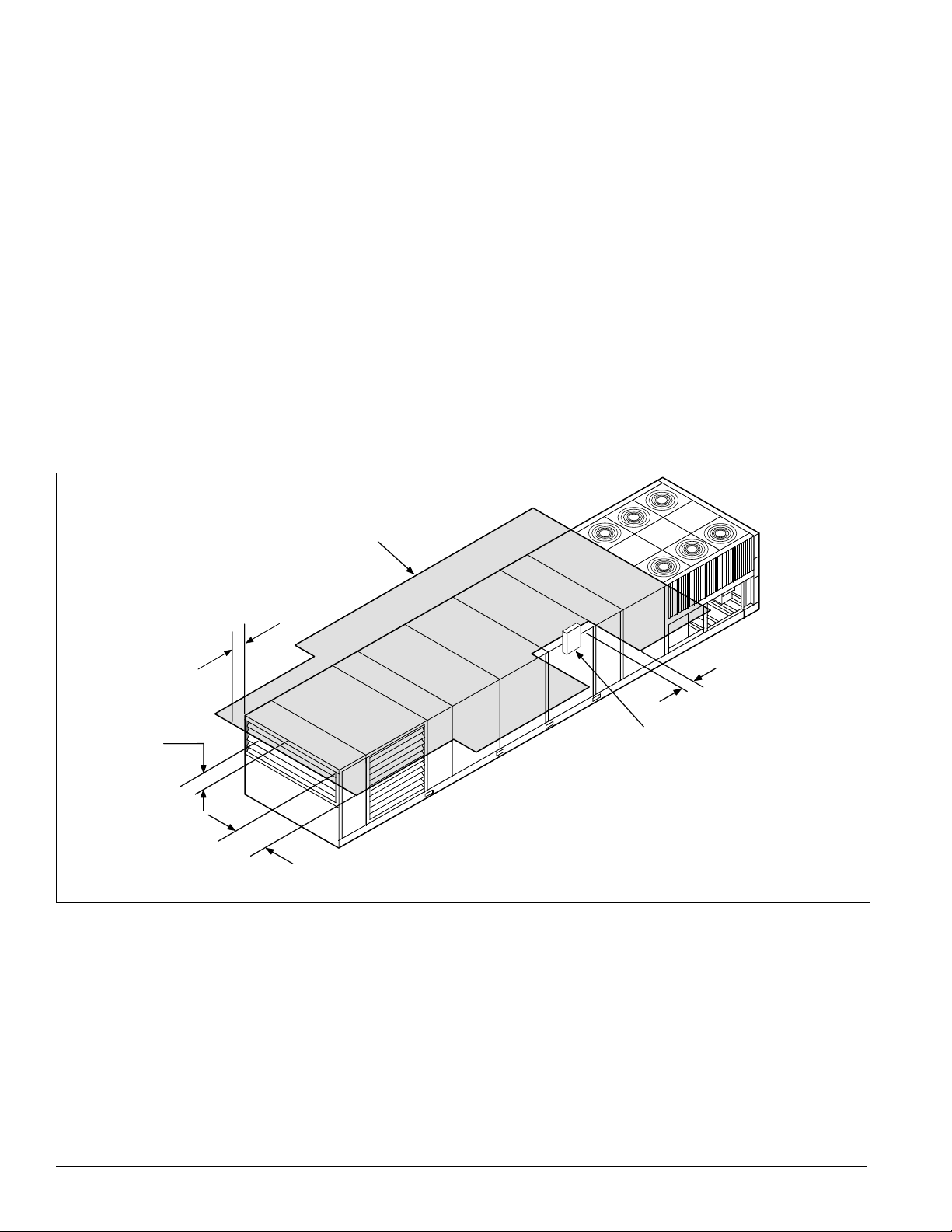
Post and Rail Mounting
When mounting by post and rail, run the structural support the
full length of the unit. Locate the structural member at the base
of the unit as shown in Figure 37, assuring the I-beam is well
supported by the structural member.
CAUTION
The unit must be level side to side and over the entire length.
Equipment damage can result if the unit is not level.
If resilient material is placed between the unit and the rail,
insert a heavy steel plate between the unit and the resilient
material to distribute the load. Seal cabinet penetrations
(electrical, piping, etc.) properly to protect against moisture
and weather.
Figure 37: Post and rail mounting
hook should always be longer than the distance between the
outer lifting points.
If the unit is stored at the construction site for an intermediate
period, follow these additional precautions:
1 Support the unit well along the length of the base rail.
2 Level the unit (no twists or uneven ground surface).
3 Provide proper drainage around the unit to prevent flooding
of the equipment.
4 Provide adequate protection from vandalism, mechanical
contact, etc.
5 Securely close the doors.
6 If there are isolation dampers, make sure they are properly
installed and fully closed to prevent the entry of animals
and debris through the supply and return air openings.
7 Cover the supply and return air openings on units without
isolation dampers.
Figure 38 shows an example of the rigging instruction label
shipped with each unit.
WARNING
Use all lifting points. Improper lifting can cause severe personal
injury and property damage.
Maximum recommended width for structural member is 5" (127 mm) to
allow for adequate space for duct connections and electrical entry.
Table 7: “W” dimension (Figure 37)
Unit
015C-040C 94 2388
045C-135C 99 2538
Dimension “W”
inches mm
Rigging and Handling
Lifting brackets with 2" (51 mm) diameter holes are provided
on the sides of the unit.
Use spreader bars, 96" to 100" (2438 to 2540 mm) wide, to
prevent damage to the unit cabinet. Avoid twisting or uneven
lifting of the unit. The cable length from the bracket to the
Figure 38: Rigging and handling instruction label
Unit has either four or six lifting points (four-point shown below).
Rigging cables must be at least as long as distance “A.”
Spreader bars
required
A
Caution: Lifting points may not
be symmetrical to center of
Lift only as indicated
gravity of unit. Balast or unequal
cable lengths may be required.
CAUTION
Lifting points may not be symmetrical to the center of gravity of
the unit. Ballast or unequal cable lengths may be required.
34 McQuay IM 738-2
Page 35

Mechanical Installation
Lifting Points
To determine the required lifting cable lengths and whether
four-point or six-point lifting is required, use Tables 10 and 11
and Figures 39 and 40.
Referring to Figure 39 and Figure 40, note that dimension A is
the distance between the outer lifting points. The four outer
rigging cables must be equal to or longer than dimension A.
Dimension B shows the minimum distance between the outer
and the inner lifting points for six-point lifting. Use this to
roughly determine the required length of the middle cables for
six-point lifting. Determine dimension A by subtracting
dimensions X and Y from dimension Z (e.g., A = Z – X – Y).
• Where:
• Z = Total unit length in inches
(refer to certified drawings for this dimension).
• X = Outdoor/return air section length (refer to Table 10 for
this dimension).
• Y = Refer to Table 11 for this dimension (see Figure 39 and
Figure 40). If A ≤ 288" (7315 mm), 4-point lifting is
sufficient.
• If A > 288" (7315 mm), 6-point lifting is required.
Table 8: Economizer section
Type of economizer
section
100% OA 0 0
Plenum 48” (1219 mm) 72” (1829 mm)
0–30% OA 48” (1219 mm) 72” (1829 mm)
0–100% economizer 72” (1829 mm) 96” (2438 mm)
0–100% economizer with return fan 72” (1829 mm) 96” (2438 mm)
Table 9: Outdoor/return air section
Outdoor/return air section 800C 802C
100% OA 0 0
Plenum 40” (1016 mm) 52" (1321 mm)
0–30% OA 40” (1016 mm) 52" (1321 mm)
0–100% economizer 40” (1016 mm) 52" (1321 mm)
0–100% economizer with 15" return fan 62" (1575 mm) —
0–100% economizer with 30" return fan 52" (1321 mm) 52" (1321 mm)
0–100% economizer with 40" return fan — 80" (2032 mm)
047C 077C
Table 10: “X” dimension (Figure 39 and Figure 40)
Outdoor/return air section
100 O.A. 00000000
Plenum 40 1016 52 1321 48 1259 72 1829
0–30% O.A. 40 1016 52 1321 48 1259 72 1829
0–100% economizer 40 1016 52 1321 72 1829 96 2438
0–100% economizer with 15” return fan 62 1575 — — — — — —
0–100% economizer with 30” return fan 52 1321 52 1321 — — — —
0–100% economizer with 40” return fan — — 80 2032 — — — —
0–100% economizer with return fan — — — — 72 1829 96 2438
015C–030C 036C–040C 045C–075C 080C–135C
in mm in mm in mm in mm
Table 11: “Y” dimension (Figure 39 and Figure 40)
RPS unit size Dimension “Y”
015C–030C 49.5" (1257 mm)
036C & 040C 38.2" (970 mm)
045C–090C 39.5" (1003 mm)
105C 30.5" (775 mm)
115C–135C 39.5‘” (1003 mm)
McQuay IM 738-2 35
Page 36

Mechanical Installation
Figure 39: Unit type RPS/RDT lifting points Figure 40: Unit type RFS or RPS/RDT factory split at
condenser
4 L i f t i n g P o i n t s
4 L i f t i n g P o i n t s
Y
A
Z
X
X
A
Z
Y = 0
36 McQuay IM 738-2
Page 37

Mechanical Installation
(
)
Figure 41: Unit type RCS
4 L i f t i n g P o i n t s
A
4 L i f t i n g P o i n t s
Figure 43: RPS factory split at supply fan section
0 1 5 C - 0 3 0 C : A M i n . = 3 3 . 9 " ( 8 6 1 m m )
A
0 3 6 C & 0 4 0 C : A M i n . = 8 5 . 6 " ( 2 1 7 4 m m )
Figure 42: Unit type RCS or condenser section from RPS/
RDT factory split at condenser
B
0 4 5 C – 0 6 0 C : B ( mi n .) = 5 7 " ( 1 4 4 8 m m )
0 7 0 C : B ( mi n .) = 9 3 " ( 2 3 6 2 m m )
C – 105
115C – 135C: B
min.) = 113" (2870 cm
045C–090C: B (Min.) = 72" (1829 mm)
105C–115C: B (Min.) = 96" (2438 mm)
125C–135C: B (Min.) = 120" (3048 mm)
McQuay IM 738-2 37
Page 38

Mechanical Installation
Reassembly of Split Units
Although RoofPak units typically ship from the factory as
complete units, they may be split at the factory in one of three
possible configurations.
1 The RFS air handler section and RCS condenser section
ship as two separate units, each with its own power supply
and unit nameplate. This configuration is ordered when the
condenser is intended to remain remote from the air handler
because of space or structural constraints.
On all units except the RFS with end discharge, refrigerant
piping is stubbed out the exterior of the cabinet for
convenient field piping between the RCS and RFS units,
and all necessary refrigeration components are provided.
Detailed instructions are on pages 47 to 52.
2 The RPS/RDT unit factory split at the condenser ships as
an air handler section and a condenser section that is
recoupled together on the roof. This configuration is
ordered if a packaged RPS unit is desired, but cannot go to
the job site because of shipping length or weight
limitations. A single nameplate is attached to the air
handler section and power is fed to both sections through
the main control box, as in a non-split RPS/RDT unit.
Detailed instructions are on pages 42 to 46.
All interconnecting piping and refrigeration components
are provided so that when the sections are coupled
together, only field-provided couplings are required to
connect the piping.
3 The RPS unit factory split at the fan ships as two pieces,
split at the supply fan bulkhead, to recouple together on the
roof. Like the RPS/RDT unit factory split at the condenser,
this configuration is ordered if shipping length or weight
limitation prevents a packaged RPS/RDT from being
ordered. Splitting at the fan has the advantage of leaving all
factory refrigerant piping intact so field evacuation and
charging is not required. Detailed instructions are on pages
38 to 41.
A single nameplate is attached to the air handler section
and power is fed to both sections through the main control
box, as in a non-split RPS/RDT unit.
RPS/RDT Factory Split at Fan
Field reassembly of an RPS/RDT unit that shipped split at the
fan takes place in three phases: (1) setting the sections,
(2) mechanically recoupling the cabinet, and (3) reconnecting
power and control wiring.
Phase I. Set sections (Figure 44)
1 Remove top cap and save for Phase II, Step 1.
2 Remove screws on fan panel, leaving retainer clips in place
to secure bulkhead. Save screws for Phase II, Step 5.
3 Remove plywood and retaining angles from unit and
discard.
4 Carefully lower both sections of unit (fan end and
discharge end) into place, making sure the roof curb
engages the recesses in the unit base.
38 McQuay IM 738-2
Page 39

Figure 44: Set sections, Steps 1–4
Remove top cap and
save for reassembly.
Mechanical Installation
Remove plywood and retaining
angles from unit and discard.
Discharge end of unit
Fan end of unit
Remove screws on fan panel,
leaving retainer clips in place.
Save screws for reassembly.
McQuay IM 738-2 39
Page 40

Mechanical Installation
Phase II. Reassemble cabinet (Figure 45)
1 Reinstall top cap removed in Phase I, Step 1.
2 Caulk (watertight) ends of splice cap.
3 Caulk (watertight) vertical seam.
4 Install #10 screws (provided).
5 Install screws (.25–20 ×.75) removed in Phase I, Step 2.
6 Install splice cover (provided).
Figure 45: Reassemble cabinet
Reinstall top cap
saved in step 1
Caulk ends
of splice cap
Splice cover,
provided
See detail
Caulk
vertical
seam
Install screws
(.25 to 20 × .75)
saved from step 1
#10 screws,
provided
Nut clip-on,
provided
40 McQuay IM 738-2
Page 41

Mechanical Installation
Phase III. Reconnect power and control wiring
The DX coil/condenser section contains power and control
harnesses that have their excess length in the blank or heat
section, which normally is immediately downstream of the fan.
Once the sections are physically reconnected, the ends of the
power harness are fed back through the unit base into the
junction box, per the unit’s electrical schematics.
CAUTION
Connect the power block correctly and maintain proper
phasing. Improper installation can cause severe equipment
damage.
1 Make electrical connections and reinstall inner raceway
cover as shown in Figure 46.
Figure 46: Electrical connections and raceway cover
installation
If applicable, install as shown
with provided fasteners.
After routing wires,
install inner raceway
cover (see step 6).
3.72 ref.
(94 mm)
2
When power wire reconnection is complete, reinstall the
inner raceway cover in the blank or heat section. Figure 46
shows a typical installation of the raceway cover.
3 Run the control harnesses by removing the external
raceway covers on either side of the unit split.
4 Remove the excess harness length from the external
raceway on the DX side of the split; then route along the
raceway, through the bushed hole in the fan section and into
the junction box where control wiring terminal blocks are
provided for reconnection.
5 Make all electrical connections per the unit’s electrical
schematics.
6 Reinstall the external raceway covers after routing of the
control wires is complete.
7 Draw through cooling coils only. Reconnect refrigerant
piping. These refrigerant circuits for these units are shipped
with a holding charge only. Figure 47 illustrates what the
installer sees at the shipping split
a To bridge the gap and connect the piping, remove the
refrigerant piping caps and add fittings and copper
tubing, as required.
b Evacuate and charge the unit. See page 48 for further
details.
Figure 47: Refrigerant lines
Capped
refrigerant
lines
McQuay IM 738-2 41
Page 42

Mechanical Installation
p
RPS/RDT Factory Split at Condensing Unit
3 Loosen piping brackets and clamps on both sections so
Field reassembly of an RPS/RDT unit that has shipped split at
the condenser takes place in three phases: (1) setting the
sections and mechanically recoupling the cabinet,
(2) reconnecting refrigerant piping, and (3) reconnecting
power and control wiring.
4 Physically rig the air handler section into place.
5 After air handler is installed, remove lifting bracket and
Phase I. Set sections and reassemble cabinet
1 Before setting sections together, remove top cap on air
handler section and wire cover on condensing section. See
Figure 48. Discard wire cover.
2 Remove piping cover and discard. Reinstall screws in holes
to prevent water leakage.
Figure 48: RPS/RDT split at condensing unit reassembly, Steps 1–6
Step 3: Loosen piping
clamps and move pipes
Step 1: Remove top cap
and save for step 10.
RFS air
handler unit
to prevent piping
interference during
reassembly (suction,
liquid, and hot gas
bypass lines).
6 On condenser unit, remove bolts adjacent to lifting bracket
refrigerant lines can be moved out of the way to prevent
interference and damage as the sections are set together.
See Figure 48.
adjacent bolts on air handler unit (see Figure 48) and save
for Step 7. Discard lifting bracket.
If unit is post-and-rail mounted on a structural beam that
runs the full length of the unit, leave bolts and lifting
brackets in place.
and save for Step 12.
RCS
condensing
unit
Step 2: Remove piping cover
and discard. Reinstall screws
to prevent water leakage.
Step 6: Remove bolt
and save for step 7.
Step 5: After main unit is installed,
remove lifting bracket on both sides
and discard. Save bolts for ste
Note: RFS units with front discharge do NOT include refrigerant piping to the DX coil. Field piping is required.
7.
7 Install condenser support on air handler unit as shown in
Figure 49. Fill unused holes in unit base with bolts saved in
Step 6.
Step 1: Before units are assembled,
remove wire cover and discard.
If unit is post-and-rail mounted on a structural beam that
runs the full length of the unit, bolts and lifting brackets
were not removed. Omit this step.
Step 6: Remove bolt
and save for step 12.
42 McQuay IM 738-2
Page 43

Mechanical Installation
Figure 49: Installing condenser support, Step 7
I n s t a l l c o n d e n s e r s u p p o r t
o n m a i n u n i t a s s h o w n w i t h
b o l t s s a v e d f r o m s t e p 1 ( t y p .
b o t h s i d e s o f u n i t ) ;
h o l e s i n u n i t b a s e w i t h b o l t s
s a v e d f r o m S t e p 1 .
f i l l u n u s e d
Figure 50: Setting condenser unit in place, Steps 8 and 9
Step 8: Lower condenser unit
until nearly level with main unit.
8
Lower the condenser unit until nearly level with main unit.
See Figure 50.
9 Carefully shift condenser unit until it rests against the main
unit. See Figure 50.
CAUTION
Do not damage piping components while setting
condensing unit in place.
CAUTION
Support condenser unit by crane during Step 9 since
condenser support rail is not designed to withstand the
heavy lateral forces of a unit being slid over it.
RFS unit
RFS unit
10
After condenser unit is set in place, install the top cap saved
in Step 1. See Figure 51.
11 Caulk (watertight) ends of splice cap and vertical seam. See
Figure 51.
Step 9: Carefully shift condenser unit
until it is resting against main unit.
CAUTION: Condenser support rail is
not designed to withstand heavy
lateral forces of unit being slid over it.
During this step, support condensing
unit with a crane.
Condenser
support rail
12 Install 1/2" bolt removed in Step 5. See Figure 51.
13 Install splice cover (provided), see Figure 51.
McQuay IM 738-2 43
Page 44

Mechanical Installation
p
Figure 51: Caulk and install parts, Steps 10–14
Reinstall top cap
saved from Step 1
Caulk ends of
splice cap
Reinstall 1/2" bolt
saved from Ste
1
Phase II. Reconnect refrigerant piping
All refrigerant piping required to reconnect the two sections is
provided so when the piping closures are cut off, piping from
the air handler and condenser sections lines up.
1 Connect piping using field-supplied couplings.
2 As with RFS/RCS units, both sections of the RPS/RDT
split-at-condenser unit ship from the factory with a holding
charge. Before removing the piping closures, inspect the
unit for line breakage or loosening of fittings.
Nut clip-on provided
3 Perform pressure testing as described in the “Leak Testing”
section on page 47.
4 Perform evacuation, charging the system, and refrigerant
charge requirements for the split-at-condenser unit per
procedures on page 47.
Note – Use Tables 15 to 18 on pages 49 to 50 to determine
refrigerant charge requirements for the RPS/RDT
split-at-condenser. Because no field-installed refrigerant
piping is required, the total charge per circuit is the sum of
the base R-22 charge and the DX coil charge.
44 McQuay IM 738-2
Page 45

Figure 52: RFS/RCS 015 to 030 refrigerant piping connections
Y
Y
Y
L 1
X
L 2
H G 1
H G 2
L 2
Y
S 2
X
S 1
S 2
H G 2
H G 1
Note: RFS units with front discharge do NOT include refrigerant piping to the DX coil. Field piping is required.
Figure 53: RFS/RCS 036 and 040 refrigerant piping connections
Mechanical Installation
S 1
L 1
L 1
L 2
H G 1
H G 2
L 2
S 2
S 1
X
H G 2
X
S 2
S 1
H G 1
L 1
Note: RFS units with front discharge do NOT include refrigerant piping to the DX coil. Field piping is required.
Table 12: Connection sizes and locations, Figures 52 and 53
Component circuit
015C 020C 025C
S1 Suction line Ckt.1 1 1/8 1 1/8 1 5/8 1 5/8 9.00 5.70 67.60 6.25 8.25 5.70 59.50 19.30
S2 Suction line Ckt.2 1 3/8 1 5/8 1 3/8 1 5/8 14.00 5.70 28.00 6.25 13.25 5.70 34.60 19.30
L1 Liquid line Ckt.1 5/8 5/8 7/8 7/8 56.00 32.00 75.00 6.25 79.00 25.00 70.50 25.00
L2 Liquid line Ckt.2 7/8 7/8 7/8 7/8 7.60 28.00 21.00 6.25 15.00 25.00 23.50 25.00
HG1 HGBP line Ckt.1 7/8 7/8 7/8 7/8 52.00 10.00 60.80 6.25 67.00 6.70 64.60 6.60
HG2 HGBP line Ckt.2 7/8 7/8 7/8 7/8 36.00 16.00 35.50 6.25 32.00 6.70 29.50 6.00
Connection sizes Connection locations
030Cto
040C
RFS 015 to 030 RCS 015 to 030 RFS 036 and 040 RCS 036 and 040
X (in.) Y (in.) X (in.) Y (in.) X (in.) Y (in.) X (in.) Y (in.)
McQuay IM 738-2 45
Page 46

Mechanical Installation
Figure 54: RPS/RDT (split)/RFS/RCS 045 to 135 refrigerant piping connections
Note: RFS units with front discharge do NOT include refrigerant piping to the DX coil. Field piping is required.
Table 13: Connection sizes and locations, Figure 54
Connection sizes Connection locations
Component circuit
S1 Suction line Ckt.1 1 5/8 2 1/8 2 1/8 2 5/8 11.7 5.2 21. 7.0 5.7 11.7
S2 Suction line Ckt.2 1 5/8 2 1/8 2 1/8 2 5/8 7.5 5.2 16.5 7.0 5.7 7.5
L1 Liquid line Ckt.1 7/8 7/8 1-1/8 1 1/8 81.5 29.1 81.5 29.1 29.1 81.4
L2 Liquid line Ckt.2 7/8 7/8 1 1/8 1 1/8 10.3 29.1 10.3 29.1 29.1 10.4
HG1 HGBP line Ckt.1 7/8 7/8 7/8 7/8 52.1 10.4 52.1 10.4 10.4 52.1
HG2 HGBP line Ckt.2 7/8 7/8 7/8 7/8 40.9 4.7 40.9 4.7 4.7 40.9
045C
050C to
075C
Phase III. Reconnecting power and control wiring
The wire harnesses are coiled in the condenser section base rail
(see Figure 55). The power wires into the lower base rail
080C to
90C
105C to
135C
air handler raceway and into the main control cabinet and
plug into the plug patch panel.
Figure 55: Connecting power and control wiring (015 to 040)
RPS (split) and
RFS 045 to 075C
X (in.) Y (in.) X (in.) Y (in.) X (in.) Y (in.)
RCS 045 to 075C 080 to 135C
raceway and the control wires into the upper raceway.
1 Uncoil the harnesses and feed them through the base rail of
the air handler section and make the proper connections.
The power wires terminate to the load side of the
contactors; the control wires plug into the plug patch panel.
2 The liquid line solenoid valve harness is split into two
harnesses. Install one half in the plug patch panel in the
main control box (see Figure 55).
3 The other half of the harness is located in conduit on the
bulkhead of the air handler section (see Figure 55).
4 Terminate the conduit to the vertical raceway in the
condenser section (see Figure 56).
5 Wire nut the ends of the two harnesses together.
6 The optional hot gas bypass solenoid valve harness is
coiled in the upper raceway of the condenser base rail (see
Figure 56). Route the plug end of the harness through the
46 McQuay IM 738-2
Page 47

Mechanical Installation
y
s
c
Figure 56: Remove vertical raceway
R e m o v a b l e v e r t i c a l
A i r H a n d l e r
S e c t i o n
C o n d e n s e r
S e c t i o n
R e m o v e
h i p p i n g
o v e r
r a c e w a y s h i p s
w i t h c o n d e n s e r
s e c t i o n s
C o n t r o l w i r e s b u n d l e d a n d
t a p e d i n s i d e t h i s r a c e w a y
P o w e r w i r e s b u n d l e d a n d
t a p e d i n s i d e t h i s r a c e w a
RFS/RCS Permanent Split Systems
Piping Recommendations
1 Use type K or L clean copper tubing. Thoroughly clean or
braze all joints with high temperature solder. Make sure
nitrogen is flowing through the tubes while brazing to
minimize the formation of oxide contaminants.
2 Base piping sizes on temperature/pressure limitations as
recommended in the following paragraphs. Under no
circumstances should pipe size be based strictly upon coil
or condensing unit piping connection size.
3 Do not exceed suction line piping pressure drop equivalent
to 2°F (1°C), 3 psi (20.7 kPa) per 100 feet (30.5 m) of
equivalent pipe length. After the suction line size is
determined, check the vertical suction risers to verify that
oil will be carried up the riser and back to the compressor.
Pitch the suction line(s) in the direction of refrigerant flow
and make sure they are adequately supported. Lines should
be free draining and fully insulated between the evaporator
and the compressor. Install a trap on the vertical riser to the
compressor.
4 To determine the minimum tonnage required to carry oil up
suction risers of various sizes, check the vertical suction
risers using Table 14.
Table 14: Minimum tonnage (R-22 or R-407C) to carry oil up
suction riser at 40°F saturated suction
Line size O.D. Minimum tonnage
1 1/8" 1.5
1 3/8" 2.5
1 5/8" 3.8
2 1/8" 7.6
2 5/8" 13.10
3 1/8" 20.4
3 5/8" 29.7
4 1/8" 41.3
5 Size the liquid line for a pressure drop not to exceed the
pressure equivalent of 2°F (1°C), 6 psi (41.4 kPa)
saturated temperature. The RFS unit includes a factory
installed filter-drier, solenoid valve, and sightglass in
each liquid line, upstream of the thermostatic expansion
valve.
Holding Charge
The RFS unit and RCS unit ship with a nitrogen holding
charge. At the time the unit is received, a visual inspection of
the unit piping should be made to be sure no breakage
occurred or that the fittings did not loosen during shipping. A
pressure test on the RCS units should indicate a positive
pressure in the unit. If no pressure is evident, the unit must be
leak tested and the leak repaired. Note and report this to the
McQuay sales representative and freight carrier (if the loss is
due to shipping damage).
WARNING
Before applying heat to remove brazed piping caps and plugs,
always vent piping to atmosphere. Failure to do so can cause
hazardous pressures, explosion, severe personal injuries, or
death.
RCS—Vent to atmosphere by opening gauge ports at the
compressors and liquid line shutoff valves. Make sure manual
valves are not back seated to shut off the gauge ports.
RFS—Vent to atmosphere by cutting off the process tubes on
the suction line caps.
The RFS unit does not have gauge ports for pressure
measurement. If no positive pressure is detected when cutting
off the process tubes and removing the tubing caps, the unit
should be leak tested as described below, after the
interconnecting piping has been brazed in place. This test will
also confirm the integrity of the field braze joints.
Leak Testing
In the case of loss of the nitrogen holding charge, the unit
should be checked for leaks prior to charging the complete
system. If the full charge was lost, leak testing can be done by
charging the refrigerant into the unit to build the pressure to
approximately 10 psig and adding sufficient dry nitrogen to
bring the pressure to a maximum of 125 psig. The unit should
then be leak tested with halide or electronic leak detector.
After making any necessary repair, the system should be
evacuated as described in the following paragraphs.
WARNING
Do not use oxygen or air to build up pressure. Explosion hazard
can cause severe personal injury or death.
McQuay IM 738-2 47
Page 48

Mechanical Installation
Evacuation
After determining the unit is tight and there are no refrigerant
leaks, evacuate the system. Use a vacuum pump with a
pumping capacity of approximately 3 cu.ft./min. and the
ability to reduce the vacuum in the unit to at least 1 mm (1000
microns).
1 Connect a mercury manometer or an electronic or other
type of micron gauge to the unit at a point remote from the
vacuum pump. For readings below 1 millimeter, use an
electronic or other micron gauge.
2 Use the triple evacuation method, which is particularly
helpful if the vacuum pump is unable to obtain the desired
1 mm of vacuum. The system is first evacuated to
approximately 29" (740 mm) of mercury. Then add enough
refrigerant vapor to the system to bring the pressure up to 0
pounds (0 microns).
3 Evacuate the system again to 29" (740 mm) of vacuum.
Repeat his procedure three times. This method is most
effective by holding system pressure at 0 pounds
(0 microns) for a minimum of 1 hour between evacuations.
The first pulldown removes about 90% of the
noncondensables; the second removes about 90% of that
remaining from the first pulldown. After the third
pulldown, only 1/10 of 1% of noncondensables remains.
Table 20 on page 51 shows the relationship between pressure,
microns, atmospheres, and the boiling point of water.
CAUTION
Before replacing refrigerant sensors or protective devices, see
“Refrigerant Charge” on page 52 for an important warning to
prevent an abrupt loss of the entire charge.
CAUTION
To prevent liquid return and damage to the compressor on
systems with optional hot gas bypass, locate the bypass
solenoid valve on the RCS, not on the RFS unit.
CAUTION
To service liquid line components, the manual shutoff valve is
closed and refrigerant is pumped into the condenser. The
pounds of refrigerant in the system may exceed the capacity of
the condenser, depending on the amount of refrigerant in the
liquid lines between the RFS and RCS units. Suitable means of
containing the refrigerant is required.
48 McQuay IM 738-2
Page 49

Mechanical Installation
Table 15: Approximate R-22 refrigerant charge per circuit, 015 to 018, 020C to 040C
Base charge
Unit size
015 to 018 11 18 0.8/1.5 .5 1 47
020C 11 18 0.8/1.5 1 1 47
025C 23 22 1.7 1 1 72
030C 23 21 1.7 1 1 72
036C 32 32 1.7 1 1 106
040C 33 32 1.7 1 1 106
* Condenser pumpdown capacity is the total charge for both circuits and is based on volume between condenser entrance and liquid line
solenoid at 90°F, 90% full
lbs per circuit (less DX coil)
Circuit #1 Circuit #2 Circuit #1 Circuit #2
EVAP.coil
(lbs/CKT/coil row)
Additional charge for heat
section additional length
Condenser pumpdown
capacity*
(lbs)
Table 16: Approximate R-22 refrigerant charge per circuit, 045C to 135C
Base charge
Unit size
045C 34 33 34 28 2.5 — 108
050C 34 33 35 34 2.5 3.0 108
060C 35 34 35 34 2.5 3.0 108
070C 39 39 40 40 2.5 3.0 134
075C 39 39 40 40 2.5 3.0 134
080C 40 41 37 38 4.1 4.7 140
090C 46 47 44 47 4.1 4.7 160
105C 50 51 45 48 4.9 6.5 208
115C 59 60 60 63 4.9 6.5 208
125C — 60 — 65 — 6.5 208
135C — 60 — 65 — 6.5 208
* DX coil configuration (S = Standard, L = Large) is identified by the eighth digit of the RPS/RDT or RFS model number, found on the unit
nameplate. For example, DX = L for unit model number RFSO6OCLY.
** Condenser pumpdown capacity is the total charge for both circuits and is based on volume between condenser entrance and liquid line
solenoid at 90ºF, 90% full.
Circuit #1 Circuit #2 Circuit #1 Circuit #2
lbs per circuit (less DX coil)
RPS RDT
DX coil charge
lbs per circuit per coil row
DX=S* DX=L*
Condenser pumpdown
capacity**
(lbs)
Table 17: Approximate R-407C refrigerant charge per circuit, 015C to 040C
Unit size
015C to 018C 10 16 0.7/1.4 .5 1 45
020C 10 16 0.7/1.4 1 1 45
025C 21 20 1.6 1 1 68
030C 21 19 1.6 1 1 68
036C 29 29 1.6 1 1 101
040C 30 29 1.6 1 1 101
* Condenser pumpdown capacity is the total charge for both circuits and is based on volume between condenser entrance and liquid line
solenoid at 90°F, 90% full
Base charge
lbs per circuit (less DX coil)
Circuit 1 Circuit 2 Circuit 1 Circuit 2
Evaporator coil
(lbs/CKT/coil row)
Additional charge for heat
section additional length
Condenser pumpdown
capacity* (lbs)
McQuay IM 738-2 49
Page 50

Mechanical Installation
Table 18: Approximate R-407C refrigerant charge per circuit, 045C to 135C
Base charge
Unit size
045C 31 30 31 26 2.3 — 103
050C 31 30 32 31 2.3 2.8 103
060C 32 31 32 31 2.3 2.8 103
070C 36 36 37 37 2.3 2.8 127
075C 36 36 37 37 2.3 2.8 127
080C 37 37 34 35 3.8 4.3 134
090C 42 43 41 43 3.8 4.3 152
105C 46 42 41 44 4.5 6.0 198
115C 54 55 55 58 4.5 6.0 198
125C — 55 — 60 — 6.0 198
135C — 55 — 60 — 6.0 198
* DX coil configuration (S = Standard, L = Large) is identified by the eighth digit of the RPS/RDT or RFS model number, found on the unit
nameplate. For example, DX = L for unit model number RFSO6OCLY.
* Condenser pumpdown capacity is the total charge for both circuits and is based on volume between condenser entrance and liquid line
solenoid at 90ºF, 90% full.
Circuit #1 Circuit #2 Circuit #1 Circuit #2
lbs per circuit (less DX coil)
RPS RDT
DX coil charge
lbs per circuit per coil row
DX=S* DX=L*
Condenser pumpdown
capacity**
(lbs)
Table 19: Weight of refrigerant in copper lines (pounds per 100 feet of Type L tubing)
O.D. line size
3/8" 0.054 3.84 3.64 0.20 0.46 0.052 0.047 0.077 0.071
1/2" 0.100 7.12 6.74 0.37 0.85 0.096 0.088 0.143 0.132
5/8" 0.162 11.53 10.92 0.61 1.38 0.156 0.142 0.232 0.214
7/8" 0.336 23.92 22.65 1.26 2.87 0.324 0.294 0.480 0.444
1 1/8" 0.573 40.80 38.62 2.14 4.89 0.552 0.501 0.819 0.756
1 3/8" 0.872 62.09 58.77 3.26 7.44 0.840 0.763 1.247 1.151
1 5/8" 1.237 88.07 83.37 4.63 10.55 1.191 1.082 1.769 1.633
2 1/8" 2.147 152.87 144.71 8.03 18.31 2.068 1.879 3.070 2.834
2 5/8" 3.312 235.81 223.23 12.38 28.25 3.189 2.898 4.736 4.372
3 1/8" 4.728 336.63 318.67 17.68 40.33 4.553 4.137 6.761 6.241
3 5/8” 6.398 455.54 431.23 23.92 54.57 6.161 5.598 9.149 8.445
4 1/8" 8.313 591.89 560.30 31.08 70.91 8.005 7.274 11.888 10.973
Vol. per 100 ft
in cubic feet
Liquid @100°F Hot gas@120°F cond. Suction gas (superheat to 85°F)
R-22 R-407C R-22 R-407C
Weight of refrigerant, lbs./100 feet
30°F 40°F
R-22 R-407C R-22 R-407C
50 McQuay IM 738-2
Page 51

Table 20: Pressure-vacuum equivalents
Absolute pressure above zero Vacuum below 1 atmosphere
Microns PSIA Mercury (mm) Mercury (in)
0 0 760.00 29.921 — —
50 0.001 759.95 29,920 1/15,200 –50
100 0.002 759.90 29.920 1/7,600 –40
150 0.003 759.85 29.920 1/5,100 –33
200 0.004 759.80 29.910 1/3,800 –28
300 0.006 759.70 29.910 1/2,500 –21
500 0.009 759.50 29.900 1/1,520 –12
1,000 0.019 759.00 29.880 1/760 1
2000 0.039 758.00 29.840 1/380 15
4,000 0.078 756.00 29.760 1/189 29
6000 0.117 754.00 29.690 1/127 39
8,000 0.156 752.00 29.600 1/95 46
10,000 0.193 750.00 29.530 1/76 52
15,000 0.290 745.00 29.330 1/50 63
20,000 0.387 740.00 29.130 1/38 72
30,000 0.580 730.00 28.740 1/25 84
50,000 0.967 710.00 27.950 1/15 101
100,000 1.930 660.00 25.980 2/15 125
200,000 3.870 560.00 22.050 1/4 152
500,000 9.670 260.00 10.240 2/3 192
760,000 14.697 0 0 1 atmosphere 212
Approximate fraction
of 1 atmosphere
H2O boiling point at each
Mechanical Installation
pressure (
o
F)
Charging the System
RCS units are leak tested at the factory and shipped with a
nitrogen holding charge. If the holding charge has been lost
due to shipping damage, charge the system with enough
refrigerant to raise the unit pressure to 30 psig after first
repairing the leaks and evacuating the system.
1 After all refrigerant piping is complete and the system is
evacuated, it can be charged as described in the paragraphs
following. Connect the refrigerant drum to the gauge port
on the liquid shutoff valve and purge the charging line
between the refrigerant cylinder and the valve. Then open
the valve to the mid position.
2 If the system is under a vacuum, stand the refrigerant drum
with the connection up, open the drum, and break the
vacuum with refrigerant gas.
3 With a system gas pressure higher than the equivalent of a
freezing temperature, invert the charging cylinder and
elevate the drum above the condenser. With the drum in
this position and the valves open, liquid refrigerant flows
into the condenser. Approximately 75% of the total
requirement estimated for the unit can be charged in this
manner.
4 Refrigerant charging with Zeotropes—R-407C is a
zeotropic mixture (see “Refrigerant Leaks” on page 131).
During initial charging or “topping” off a system, it is
important to remove the refrigerant from the charging
cylinder in the liquid phase. Many of the cylinders for the
newer refrigerants use a dip tube so that in the upright
position liquid is drawn from the cylinder. DO NOT vapor
charge out of a cylinder unless the entire cylinder is to be
charged into the system. Refer to charging instructions
provided by the refrigerant manufacturer.
5 After 75% of the required charge enters the condenser,
reconnect the refrigerant drum and charging line to the
suction side of the system. Again, purge the connecting
line, stand the drum with the connection side up, and place
the service valve in the open position.
Note – Stamp the total operating charge per circuit on the unit
nameplate for future reference.
CAUTION
Adding refrigerant to the suction always risks liquid-related
damage to the compressor.
McQuay IM 738-2 51
Page 52

Mechanical Installation
Take special care to add refrigerant slowly enough to the
suction to prevent damage. Adjust the charging tank hand
valve so liquid leaves the tank but vapor enters the compressor.
This is especially true with R-407C because the charge must
be drawn from the liquid portion of the tank.
CAUTION
Units purchased for R-22 operation must be charged only
with R-22. Units purchased for R-407C operation must be
charged only with R-407C.
Field mixing or changing of refrigerants can compromise
performance and damage equipment.
Table 21: Acceptable refrigerant oils
R-22 (mineral oils)
Note: Do not use mixtures of
mineral oils and POE oils with R-
22.
Sunisco 3GS Copeland ULtra 22 CC
Texaco WF32 Mobil EAL™ Arctic 22 CC
Calumet R015 ICI EMKARATE RL™ 32CL
R-407C (polyolester [POE] oils)
Note: Do not use mineral oils
with R-407C
.
Refrigerant Charge
Each unit is designed for use with R-22 or R-407C. The total
charge per circuit is the sum of the following four values:
• Condenser section charge, see Table 15 on page 49.
• Evaporator coil charge, see Table 15 on page 49.
• Charge for length of unit piping to the evaporator coil, see
Table 15 on page 49.
• Charge for length of interconnecting piping between the
RCS and RFS units, installed by field, see Table 19 on
page 50.
The exact charge for a one piece RPS/RDT is on the unit
nameplate.
Note – The total operating charge per circuit should not exceed
the pumpdown capacity per circuit shown in Tables 15 to
19 on pages 49 to 50.
Subcooling
When field charging the unit, use the following to properly
charge the unit:
• All compressors on each circuit operating at full capacity.
• Allowable subcooling ranges are between 13°F to 20°F.
• Be sure to measure pressure and temperature at the same
location when finding/calculating subcooling. Compare the
actual temperature and pressures to the saturated liquid
temperature. R-407C example: A pressure of 250 psi is
measured at the condenser outlet. From the R-407C chart,
250 psig is approximately 108°F saturated liquid
temperature. If the actual refrigerant temperature is 98°F, the
liquid is subcooled 10°F.
• Ambient temperature must be between 60°F and 105°F.
• Hot Gas Bypass NOT operating (only if unit is supplied with
option).
• SpeedTrol motors operating at 100% (only if unit is supplied
with option).
If any one of the above items is not followed, subcooling
readings will not be accurate and the potential exists for over
or undercharging of the refrigerant circuit.
Refrigeration Service Valves
The unit is shipped with all refrigeration service valves closed.
RDT, RPS and RCS units have the following:
Sizes 15 to 105—One discharge valve is provided per
refrigerant circuit, located between the compressors and
condenser.
Sizes 115 to 135—One service valve is provided on the
discharge and suction of each compressor.
All Units—One liquid valve is provided per refrigeration
circuit, located at end of condensing section opposite
condenser control box.
RFS units do not ship with service valves installed. Before
attempting to start the compressors, all refrigeration service
valves should be fully opened and backseated.
Unit Piping
Condensate Drain Connection
• The unit is provided with a 1.5" male NPT condensate drain
connection. Refer to certified drawings for the exact
location. For proper drainage, level the unit and drain pan
side to side and install a P-trap
• RPS units may have positive or negative pressure sections.
Use traps in both cases with extra care given to negative
pressure sections. In Figure 57, dimension “A” should be a
minimum of 8" (203 mm). As a conservative measure to
prevent the cabinet static pressure from blowing or drawing
the water out of the trap and causing air leakage, dimension
A should be two times the maximum static pressure
encountered in the coil section in inches wc.
• Draining condensate directly onto the roof may be
acceptable; refer to local codes. Provide a small drip pad of
stone, mortar, wood, or metal to protect the roof against
possible damage.
• If condensate is piped into the building drainage system,
pitch the drain line away from the unit a minimum of 1/8"
per foot. The drain line must penetrate the roof external to
the unit. Refer to local codes for additional requirements.
Sealed drain lines require venting to provide proper
condensate flow.
• Where the cooling coils have intermediate condensate pans
on the face of the evaporator coil, copper tubes near both
ends of the coil provide drainage to the main drain pan.
52 McQuay IM 738-2
Page 53

Mechanical Installation
Check that the copper tubes are in place and open before the
unit is put into operation.
• On units with staggered cooling coils, the upper drain pan
drains into the lower coil drain pan through a copper tube
near the center of the drain pan. Check that this tube is open
before putting the unit into operation and as a part of routine
maintenance.
• Because drain pans in any air conditioning unit have some
moisture in them, algae, etc. will grow. Periodically clean to
prevent this buildup from plugging the drain and causing the
drain pan to overflow. Clean drain pans to prevent the spread
of disease. Cleaning should be performed by qualified
personnel
.
WARNING
Drain pans must be cleaned periodically.
Material in uncleaned drain pans can cause disease.
Cleaning should be performed by qualified personnel.
Figure 57: Condensate drain connection
can guarantee a 100% safeguard against coil freeze-up. Glycol
solutions or brines are the only freeze-safe media for operation
of water coils at low entering air temperature conditions.
When no factory piping or valve is included, the coil
connections are 1.625” ODM copper on 800 and 802C, and
2.125" ODM copper on 047 and 077C.
With the factory piping and valve package, field piping
connections are the same NPT size as the valve with female
threading (see Figure 59 on page 53).
Refer to the certified drawings for the recommended piping
entrance locations. Seal all piping penetrations to prevent air
and water leakage.
Note – Factory-installed water valves and piping are bronze,
brass, and copper. Dissimilar metals within the plumbing
system can cause galvanic corrosion. To avoid corrosion,
provide proper di-electric fittings as well as appropriate
water treatment.
Figure 58: Hot water heat section (shown with factory
valve and piping)
S e e V i e w " A "
C o p p e r T u b e
( o n e e a c h e n d o f c o i l )
S t a t i c P r e s s u r e " P "
4 " ( 1 0 2 m m )
M i n i m u m
" A "
8 " ( 2 0 3 m m )
M i n . o r 2 x " P "
( i n . w . o . )
D r a i n P a n
V i e w A
N o t e : D r a i n l i n e m u s t
n o t b e r u n h i g h e r
t h a n t h i s l e v e l
M i n i m i z e T h i s
e n s i o n
D i m
Gas Piping
See the “Installation” section of the gas-fired furnace
installation manual, Bulletin No. IM 684 or 685.
Hot Water Coil Piping
Hot water coils are provided without valves for field piping or
piped with three-way valves and actuator motors.
Note – All coils have vents and drains factory installed.
Hot water coils are not normally recommended for use with
entering air temperatures below 40°F (4°C). No control system
Figure 59: Hot water valve package
R e t u r n
B y p a s s
S u p p l y
CAUTION
Coil freeze possible. Can damage equipment.
Follow instructions for mixing antifreeze solution used. Some
products have higher freezing points in their natural state than
when mixed with water. The freezing of coils is not the
responsibility of McQuay International. Refer to “” on page 131.
McQuay IM 738-2 53
Page 54

Mechanical Installation
Steam Coil Piping
Steam coils are provided without valves for field piping, or
piped with two-way valves and actuator motors.
The steam heat coil is pitched at 1/8" (3 mm) per foot (305
mm) to provide positive condensate removal. When no factory
piping or valve is included, the coil connections are 2.5" male
NPT iron pipe.
With the factory piping and valve package, the field supply
connection is the same NPT size as the valve with female
threading (see Figure 62 on page 55).
Refer to the certified drawings for the recommended piping
entrance locations. All piping penetrations must be sealed to
prevent air and water leakage.
Note – The valve actuator spring returns to a stem up position
upon power failure. This allows full flow through the coil.
Figure 60: Steam heat section (shown with factory valve
and piping)
Steam Piping Recommendations
1 Be certain that adequate piping flexibility is provided.
Stresses resulting from expansion of closely coupled piping
and coil arrangement can cause serious damage.
2 Do not reduce pipe size at the coil return connection. Carry
return connection size through the dirt pocket, making the
reduction at the branch leading to the trap.
3 Install vacuum breakers on all applications to prevent
retaining condensate in the coil. Generally, the vacuum
breaker is to be connected between the coil inlet and the
return main. However, if the system has a flooded return
main, the vacuum breaker to the atmosphere; the trap
design should allow venting of the large quantities of air.
4 Do not drain steam mains or takeoffs through coils. Drain
mains ahead of coils through a steam trap to the return line.
5 Do not attempt to lift condensate.
6 Pitch all supply and return steam piping down a minimum
of 1" (25 mm) per 10 feet (3 m) of direction of flow.
54 McQuay IM 738-2
Page 55

Mechanical Installation
Steam Trap Recommendations
1 Size traps in accordance with manufacturers’
recommendations. Be certain that the required pressure
differential will always be available. Do not undersize.
2 Float and thermostatic or bucket traps are recommended for
low pressure steam. Use bucket traps on systems with onoff control only.
3 Locate traps at least 12" (305 mm) below the coil return
connection.
4 Always install strainers as close as possible to the inlet side
of the trap.
5 A single tap may generally be used for coils piped in
parallel, but an individual trap for each coil is preferred.
Steam Coil Freeze Conditions
If the air entering the steam coil is below 35°F (2°C), note the
following recommendations:
1 Supply 5 psi (34.5 kPa) steam to coils at all times.
2 Modulating valves are not recommended. Control should
be by means of face and bypass dampers.
3 As additional protection against freeze-up, install the tap
sufficiently far below the coil to provide an adequate
hydrostatic head to ensure removal of condensate during an
interruption on the steam pressure. Estimate 3 ft. (914 mm)
for each 1 psi (7 kPa) of trap differential required.
4 If the unit is to be operated in environments with possible
freezing temperatures, an optional freezestat is
recommended. See “Freeze Protection” on page 100 for
additional information.
Figure 61: Valve assembly
S t e m C l i p
S t e m
Figure 62: Steam valve package
S e t s c r e w s
McQuay IM 738-2 55
Page 56

Mechanical Installation
Damper Assemblies
The optional damper assemblies described in this section
normally are ordered with factory-installed actuators and
linkages. The following sections describe operation and
linkage adjustment of the factory option.
Economizer Dampers
Outside air intake is provided on both sides of the unit, and the
return air path is at the center of the damper set. As the single
actuator modulates the outside air dampers open, the return air
dampers close. Exhaust air exits the unit through the gravity
relief dampers provided at the end of the economizer section.
The damper is set so that the crankarm moves through a 90degree angle to bring the economizer dampers from full open
to full close (see Figure 63). Access to the actuator and linkage
is from the filler section. Mechanical stops are placed in the
crankarm mounting bracket. Do not remove stops. Driving the
crankarm past the stops results in damage to the linkage or
damper. The unit ships with a shipping bolt securing the
linkage crankarm. Remove shipping bolt before use.
Figure 63: Damper adjustment
Note – For good airflow control, adjust linkages so damper
56 McQuay IM 738-2
blades do not open beyond 70 degrees. Opening a
damper blade beyond 70 degrees has little effect on its
airflow.
Do not “over close” low leak damper blades. The edge
seal should just lightly contact the adjoining blade. The
blades will lock up if they are closed so far the seal goes
over center.
Page 57

Mechanical Installation
Intake Hood Damper (0% to 100% outside air)
Units requiring 100% outside air are provided with a rain hood
and dampers that can be controlled by a single actuator. The
actuator provides two-position control for opening the
dampers fully during unit operation and closing the dampers
during the off cycle. No unit mounted exhaust dampers are
provided.
Intake Hood Damper (0% to 30% outside air)
These dampers are intended to remain at a fixed position
during unit operation, providing fresh air quantities from 0 to
30% of the total system airflow, depending on the damper
setting. This setting is made at the linkage rod on units with
manually adjustable linkages.
On units provided with MicroTech II controls, the damper
position may be set at the controller keypad. During unit
operation, the two-position actuator drives the damper to the
position set on the keypad. During the off cycle, the damper is
automatically closed.
No unit-mounted exhaust dampers are provided with this
option.
Figure 64: Damper linkage bar typical for all sizes, sizes
15C to 40C shown
Figure 65: Intake hood damper adj.
Airflow
A i r f l o w
3 . 1 5 " ( 8 0 m m )
M a x . S t r o k e o f
D a m p e r L i n k a g e B a r
Note –
OA
closed
90
stroke
OA
open
.25" (6mm)
McQuay IM 738-2 57
Page 58

Mechanical Installation
Cabinet Weather Protection
This unit ships from the factory with fully gasketed access
doors and cabinet caulking to provide weather resistant
operation. After the unit is set in place, inspect all door gaskets
for shipping damage and replace if necessary.
Protect the unit from overhead runoff from overhangs or other
such structures.
Recaulk field-assembled options such as external piping or
vestibules per the installation instructions provided with the
option.
CAUTION
Transportation, rigging, or maintenance can damage the unit’s
weather seal. Periodically inspect the unit for leakage. Standing
moisture can promote microbial growth, disease, or damage to
the equipment and building.
Installing Ductwork
On bottom-supply/bottom-return units, if a McQuay roof curb
is not used, the installing contractor should make an airtight
connection by attaching field-fabricated duct collars to the
bottom surface of either the roof curb’s duct flange or the
unit’s duct opening. Do not support the total weight of the duct
work from the unit or these duct flanges. See Figure 66.
expose the discharge duct collars on a side discharge unit,
remove the plenum section access door and the door gasketing.
Use flexible connections between the unit and ductwork to
avoid transmission of vibration from the unit to the structure.
To minimize losses and sound transmission, design duct work
per ASHRAE and SMACNA recommendations.
Where return air ducts are not required, connect a
sound-absorbing T or L section to the unit return to reduce
noise transmission to the occupied space.
WARNING
Mold can cause personal injury. Materials such as gypsum wall
board can promote mold growth when damp. Such materials
must be protected from moisture that can enter units during
maintenance or normal operation.
Ductwork exposed to outdoor conditions must be built in
accordance with ASHRAE and SMACNA recommendations
and local building codes
.
NOTICE
Installer must provide access in the ductwork for
plenum-mounted controls.
Once duct work is installed in units with side discharge, access
to plenum-mounted components is difficult.
Units with optional back return, side discharge, or end
discharge (on RFS units), all have duct collars provided. To
Figure 66: Installing duct work
U n i t D u c t O p e n i n g
9 . 7 6 "
4 . 5 8 "
F l e x i b l e
C o n n e c t o r
D u c t w o r k
D u c t F l a n g e r
i n R o o f C u r b
U n i t B a s e
R o o f C u r b
58 McQuay IM 738-2
Page 59

Mechanical Installation
Installing Duct Static Pressure Sensor Taps
For all VAV units, field install and connect duct static pressure
taps to the pressure sensors in the unit. Sensor SPS1 is
standard; additional sensor SPS2 is optional. These sensors are
located in the main control panel (see “Control Panel” on page
14).
Carefully locate and install the duct static pressure sensing tap.
Improperly locating or installing the sensing tap causes
unsatisfactory operation of the entire variable air volume
system. Below are pressure tap location and installation
recommendations. The installation must comply with local
code requirements
1 Install a tee fitting with a leak-tight removable cap in each
tube near the sensor fitting. This facilitates connecting a
manometer or pressure gauge if testing is required.
2 Use different colored tubing for the duct pressure (HI) and
reference pressure (LO) taps, or tag the tubes. McQuay
recommends 1/4" plastic tubing.
3 Locate the duct pressure (HI) tap near the end of a long
duct to ensure that all terminal box take-offs along the run
have adequate static pressure.
4 Locate the duct tap in a nonturbulent flow area of the duct.
Keep it several duct diameters away from take-off points,
bends, neckdowns, attenuators, vanes, or other
irregularities.
5 Use a static pressure tip (Dwyer A302 or equivalent) or the
bare end of the plastic tubing for the duct tap. (If the duct is
lined inside, use a static pressure tip device.)
6 Install the duct tap so that it senses only static pressure (not
velocity pressure). If a bare tube end is used, it must be
smooth, square (not cut at an angle) and perpendicular to
the airstream (see Figure 68).
7 Locate the reference pressure (LO) tap somewhere near the
duct pressure tap within the building (see Figure 67). If the
reference tap is not connected to the sensor, unsatisfactory
operation will result.
8 Route the tubes between the curb and the supply duct, and
feed them into the unit through the knockout in the bottom
of the control panel (see Figure 67). Connect the tubes to
appropriate barbed fittings in the control panel. (Fittings are
sized to accept 1/4" plastic tubing.)
Figure 67: Static pressure tubing entrance location
Static pressure
tubing
Figure 68: Pressure sensing tubing installation
Main Control Panel
"HI line"
"LO" line
Remote Sense Point
To Sensor
"HI" input
Ductwork
(Remote Locat ion)
SPS1
Rubber
Grommet
Roof
Tubing Extends
thru Approx. 1/8"
To Sensor
"LO" Input
Pressure Sensing
Tubing
McQuay IM 738-2 59
Page 60

Mechanical Installation
Installing Building Static Pressure Sensor Taps
If a unit has direct building static pressure control capability,
you must field install and connect static pressure taps to
pressure sensor SPS2 in the unit. This sensor is located at the
bottom of the main control panel next to terminal block TB2.
Carefully locate and install the two static pressure sensing
taps. Improper location or installation of the sensor taps causes
unsatisfactory operation. Below are pressure tap location and
installation recommendations for both building envelope and
lab, or “space within a space” pressure control applications.
The installation must comply with local code requirements.
CAUTION
Fragile sensor fittings.
If you must remove tubing from a pressure sensor fitting, use
care. Do not use excessive force or wrench the tubing back and
forth to remove; the fitting can break off and damage sensor.
Building Pressurization Applications
1 Install a tee fitting with a leak-tight removable cap in each
tube near the sensor fitting. This facilitates connecting a
manometer or pressure gauge if testing is required.
2 Locate the building pressure (HI) tap in the area that
requires the closest control. Typically, this is a ground level
floor that has doors to the outside.
3 Locate the building tap so it is not influenced by any source
of moving air (velocity pressure). These sources may
include air diffusers or outside doors.
4 Route the building tap tube between the curb and the
supply duct and feed it into the unit through the knockout in
the bottom of the control panel (see Figure 67). Connect the
tube to the 1/4-inch HI fitting for sensor SPS2.
5 Locate the reference pressure (LO) tap on the roof. Keep it
away from the condenser fans, walls, or anything else that
may cause air turbulence. Mount it high enough above the
roof so it is not affected by snow. Not connecting the
reference tap to the sensor results in unsatisfactory
operation.
6 Use an outdoor static pressure tip (Dwyer A306 or
equivalent) to minimize the adverse effects of wind. Place
some type of screen over the sensor to keep out insects.
Loosely packed cotton works well.
7 Route the outdoor tap tube out of the main control panel
through a small field-cut opening in the edge of the control
wiring raceway cover (see Figure 67 on page 59). Cut this
“mouse hole” in the vertical portion of the edge. Seal the
penetration to prevent water from entering. Connect tube to
the 1/4-inch LO fitting for sensor SPS2.
Lab Pressurization Applications
1 Install a “T” fitting with a leak-tight removable cap in each
tube near the sensor fitting. This facilitates connecting a
manometer or pressure gauge if testing is required.
2 Use different colored tubing for the controlled space
pressure (HI) and reference pressure (LO) taps, or tag the
tubes.
3 Regardless whether the controlled space is positive or
negative with respect to its reference, locate the HI pressure
tap in the controlled space (the setpoint can be set between
–0.2 and 0.2" wc).
4 Locate the reference pressure (LO) tap in the area
surrounding the controlled space. Not locating the
reference tap to the sensor results in unsatisfactory
operation.
5 Locate both taps so they are not influenced by any source
of moving air (velocity pressure). These sources may
include air diffusers or doors between the high and low
pressure areas.
6 Route the building tap tube between the curb and the
supply duct and feed it into the unit through the knockout in
the bottom of the control panel (see Figure 67).
7 Connect the tube to the 1/4-inch HI fitting for sensor SPS2.
60 McQuay IM 738-2
Page 61

Electrical Installation
g
Electrical Installation
Field Power Wiring
Wiring must comply with all applicable codes and ordinances.
The warranty is voided if wiring is not in accordance with
these specifications. An open fuse, tripped circuit breaker, or
Manual Motor Protector (MMP) indicates a short, ground, or
overload. Before replacing a fuse, circuit breaker, MMP, or
restarting a compressor or fan motor, identify the trouble and
correct.
According to the National Electrical Code, a disconnecting
means shall be located within sight of and readily accessible
from the air conditioning equipment. The unit can be ordered
with an optional factory mounted disconnect switch. This
switch is not fused. Power leads must be over-current
protected at the point of distribution. The maximum allowable
overcurrent protection (MROPD) appears on the unit
nameplate.
All RPS, RFS, and RDT
All units are provided with internal power wiring for single or
dual point power connection. The power block or an optional
disconnect switch is located within the main control panel.
Field power leads are brought into the unit through 3"
knockouts in the bottom of the main control panel. Refer to the
unit nameplate to determine the number of power connections.
See Figure 69 and Table 23 on page 63.
WARNING
Hazardous voltage. Can cause severe injury or death.
Disconnect electric power before servicing equipment. More
than one disconnect may be required to de-energize the unit.
If the unit has a factory mounted disconnect switch, generally
the switch must be turned off to open the main control panel
door. However, the door can be opened without disconnecting
power by following the procedure covered on page 133. If this
is done, use caution since power is not removed from the unit
or the controller.
Note – To wire entry points, refer to certified drawings for
dimensions.
Figure 69: RPS/RDT and RFS power wiring connections
Electric heat
control panel
Optional
disconnect
(DS3)
3" power
knockouts
Optional
disconnect (DS2)
Main disconnect (DS1)
or power block (PB1)
3" power
knockouts
Figure 70: Optional side power wiring entrance
3 " ( 7 6 m m )
M a x D i a .
M a i n
C o n t r o l
P a n e l
R e m o v e L i f t i n g B r a c k e t
( I f L o c a t e d H e r e )
B e f o r e D r i l l i n
2 . 7 5 "
( 7 0 m m )
H o l e
1 6 "
( 4 0 6 m m )
• The preferred entrance for power cables is through the
bottom knockouts provided on the unit. If side entrance is
the only option, a drilling location is provided.
CAUTION
Wires are located in base rail. Move wires before drilling hole
through base rail.
Follow the drilling dimensions exactly to prevent damage to
the control panel. The dimensions provided are the only
possible point of side entrance for the power cables.
RCS Units
Field power wiring is connected from the main control panel in
the RFS unit to powerblock (PB4) or an optional disconnect
switch (DS4) located in the condenser control panel of the
RCS unit. Power leads enter the bottom left corner of the
McQuay IM 738-2 61
Page 62

Electrical Installation
condenser control panel through the conduit hubs shipped with
the unit. Refer to Figure 72 and Figure 73 on page 63.
Figure 71: Typical power wire entrance, unit view—RPS 015C to 040C shown (actual opening shown on submittal
documents)
20.0
10.0
6.0
76.0
3.8
86.5
94.0
3.8
Supply air opening
10.0
C
B
E
A
1.50 MPT drain
Detail B
C
3.8
0.9 Dia. K.O.
(Qty 4)
Bottom ret urn
opening
24.3
Va r ie s
based on
options
17.7
22.3
12.9
15.3
3.0 Dia. K.O.
(Qty 3)
6.8
11. 9
12.0
Reference from leaving
air end of section
8.8
7.6
6.6
3.8
All Units
The minimum circuit ampacity (wire sizing amps) is shown on
the unit nameplate. Refer to Table 23 on page 63 for the
recommended number of power wires.
Copper wire is required for all conductors. Size wires in
accordance with the ampacity tables in Article 310 of the
National Electrical Code. If long wires are required, it may be
necessary to increase the wire size to prevent excessive voltage
drop. Size wires for a maximum of 3% voltage drop. Supply
voltage must not vary by more than 10% of nameplate. Phase
voltage imbalance must not exceed 2%. (Calculate the average
voltage of the three legs. The leg with voltage deviating the
farthest from the average value must not be more than 2%
away.) Contact the local power company for correction of
improper voltage or phase imbalance.
CAUTION
Provide proper line voltage and phase balance.
Improper line voltage or excessive phase imbalance constitutes
product abuse. It can cause severe damage to the unit's
electrical components.
A ground lug is provided in the control panel for each
disconnect or power block. Size grounding conductor in
accordance with Table 250-95 of the National Electrical Code.
62 McQuay IM 738-2
Page 63

In compliance with the National Electrical Code, an
r
electrically isolated 115V circuit is provided in the unit to
supply the factory mounted service receptacle outlet and
optional unit lights. This circuit is powered by a field
connected 15A, 115V power supply. Leads are brought into the
RFS and RPS units through a 7/8" knockout in the bottom of
the main control panel, near the power wire entry point.
Figure 72: RCS 015C–030C power wiring connections
Conduit and hub
(shipped with
RCS unit)
Power block PB4
or disconnect
switch DS4
7/8" knockout for
wire entry (field to cut
larger holes as required
for power wire)
Terminal block TB8
for 115V service
receptical circuit
Figure 73: RCS 036C and 135C power wiring connections
(number of condenser fans varies per unit size)
Conduit and hub
(shipped with RCS unit)
Power block PB4 or
disconnect switch DS4
7/8" knockout for
TB8 wire entry
7/8" knockout fo
TB8 wire entry
Terminal aTB8
for 115V service
7/8" knockout for wire entry
(field to cut larger holes as
required for pwer wire)
receptical circuit
Electrical Installation
Table 22: Multiple point power connection options
Number of
electrical
circuits
2
2
3
Disconnect
designation
DS2
Load
Supply and return fan
motors plus controls
DS1 Balance of unit Main control panel
DS3 Electric heat
DS1 Balance of unit Main control panel
DS3 Electric heat
DS2
Supply and return fan
motors plus controls
DS1 Balance of unit Main control panel
Location
(see Figure 3 on
page 6)
Main control panel
Electric heat
control panel
Electric heat
control panel
Main control panel
Table 23: Recommended 3-phase power wiring to ensure
disconnects and power blocks mate with power wiring
Wire
gauge
Qty./
pole
Insulation
rating
(°C)
No. of
conduits
Conduit
(trade size, in.)
10 1 75 1 1/2 35
8 1 75 1 3/4 50
6 1 75 1 1 65
41 75 1 1 1/4 85
3 1 75 1 1 1/4 100
2 1 75 1 1 1/4 115
1 1 75 1 1 1/4 130
1/0 1 75 1 1 1/2 150
2/0 1 75 1 2 175
3/0 1 75 1 2 200
4/0 1 75 1 2 230
250 1 75 1 2 1/2 255
300 1 75 1 2 1/2 285
350 1 75 1 3 310
400 1 75 1 3 335
500 1 75 1 3 380
3/0 2 75 2 2 400
4/0 2 75 2 2 460
250 2 75 2 2 1/2 510
300 2 75 2 2 1/2 570
350 2 75 2 3 620
400 2 75 2 3 670
500 2 75 2 3 760
250 3 75 3 2 1/2 765
300 3 75 3 2 1/2 855
350 3 75 3 3 930
1.All wire sizes assume separate conduit for each set of parallel conductors.
2.All wire sizes based on NEC Table 310-16 for 75°C THW wire (copper).
Canadian electrical code wire ampacities may vary.
3.All wire sizes assume no voltage drop for short power leads.
For MCA
up to
(amps)
McQuay IM 738-2 63
Page 64

Electrical Installation
2
ol
V
Field Control Wiring
Roof Pak applied rooftop units are available with several
control arrangements which may require low voltage field
wiring. Detailed descriptions of various field control wiring
options and requirements are included in the “Field Wiring”
section of Bulletin No. IM 696, “MicroTech II Applied
Rooftop Unit Controller.” Refer to the unit wiring diagrams for
additional installation information.
Wiring must comply with applicable codes and ordinances.
The warranty is voided if wiring is not in accordance with
these specifications.
RPS, RDT, and RFS Units
All field control wiring connections are made at the class II
terminal block TB2, which is located in the main control panel.
Field wiring connections to the 115-volt receptacle and lights
are made at terminal block TB7, which is also located in the
main control panel. Refer to Figure 74 and “Control Panel” on
page 14. Two 7/8" knockouts are provided for wire entry.
Figure 74: RDT, RFS, RPS field control wiring connections
Main control panel
RFS/RCS Units
The RCS unit receives 115-volt and 240-volt control circuit
power and a number of control signals from the RFS unit. Two
7/8" knockouts are provided in the right side of the RCS
control box.
Interconnecting wiring enters the
RFS
unit through 7/8"
knockouts in the bottom of the main control panel. The
interconnecting wiring is connected to TB4 in the
RFS
unit
and TB5 in the RCS unit. Refer to Figure 75. A 7/8" knockout
is also available in the end of the unit base as shown in
Figure 74.
Note – If a single conduit containing 24V and 115V wiring is run
Figure 75: RFS and RPS interconnecting control wiring
above the roof line between the RFS and RCS, install the
24V wiring as a NEC Class I wiring system.
Main
control
panel
Condenser
control
panel
TB4
PB4/DS4P
DS2
PB1/DS1
TB5
24V
115
4V field terminal
block (TB2)
Control wiring raceway
cover (remove for access
to harness from main contr
box to unit-mounted
control devices)
WARNING
Electrical shock hazard. Can cause severe injury or death.
Connect only low voltage NEC Class II circuits to terminal block
TB5.
Reinstall and secure all protective deadfront panels when the
wiring installation is complete.
64 McQuay IM 738-2
Page 65

Preparing Unit for Operation
This b
a
Preparing Unit for Operation
WARNING
Moving machinery hazard. Can cause severe injury or death.
Before servicing equipment, disconnect power and lock off.
More than one disconnect may be required to de-energize unit.
Figure 76: RDT spring mount hold down fasteners
Hold-down
fasteners
Hold-down
fasteners
Spring Isolated Fans
Releasing Spring Mounts
The optional spring-mounted supply and return fans are locked
down for shipment. Hold-down fasteners are located at each
spring mount. Remove these fasteners before operating the
fans. Figure 79 shows a typical spring mount. Note that the
3/8" hold-down bolt securing the fan base to the unit cross
channel must be removed.
After removing the hold-down fasteners, rock the fan assembly
by hand to check for freedom of movement.
Figure 77: Spring mounted hold-down fasteners, all units
racket is added,
and these 3/8" tie downs
are used for 15–30 ton units.
Figure 78: Fan spring mount adjustment
Leveling
screw
Spring
mount
assembly
Cross
channel
* Grossly out-of-adjustment thrust restraints can affect this
dimension. Recheck after thrust restraints are adjusted.
Jam nut
Fan base
3/8" ± 1 /4"
with fan running
Adjusting Spring Mounts
To change spring compression:
Loosen the .625-18 UNF hex nut.
Place some additional weight on the fan sled frame (use a lever
to slightly compress the spring/or raise the sled) to allow the
bolt to turn freely.
Place one or two drops of oil on the threads if needed. Use a
wide, flat, blade socket drive bit with a recommended 1/2”
drive handle. Ensure that as the slotted bolt is turned, the
upper-rebound plate also turns. This action allows the bolt to
compress/decompress the compression plate, while having the
same affect on the spring. If the spring is compressed too
much, lift the sled before turning. If the spring is not
compressed enough, place weight on the sled corner to force it
down before turning.
Re-adjust the position of the lower-rebound plate so that the
sled has at lest 3/4” travel and no more than 1.25” travel.
Figure 79: Spring mount
This bracket is added,
and these 3/8" tie downs
re used for 15–30 ton units.
McQuay IM 738-2 65
Page 66

Preparing Unit for Operation
WARNING
Moving machinery hazard. Can cause severe injury or death.
Start the fans for the first time according to the “Check, Test,
and Start Procedures” on page 112. If this is not done,
equipment damage, severe personal injury, or death can occur.
Relief Damper Tie-Down
Figure 81: Thrust restraint adjustment
Jam nut A
Nut B
Spring clip
Washer
Nut C
Fan bulkhead
Economizer sections with a 30" or 40" return fan have a relief
damper that is tied down for shipping. Remove the two
brackets and two screws before operation to allow free
movement of dampers. Access is from inside the economizer
section.
Adjusting Scroll Dampers
Two sets of scroll dampers are provided in the housing of the
twin 15" x 6" supply fan to allow control of air volume to each
fan wheel. At the factory, these dampers are fully closed,
unrestricting airflow. If fan paralleling occurs, correct it by
loosening the adjustment screw on top of the fan housing (see
Figure 80) and slightly lowering the rod until air distribution
between the fans is even.
Figure 80: Scroll damper adjustment
Adjustment assembly
Scroll damper
Jam nut A
Thrust restraint angle
Fan housing frame
Detail A
See Detail A
Thrust restraint adjustment (with fan off)
1. Loosen jam nuts A.
2. Turn nut C until spring cup and washer contact thrust restraint angle.
3. Turn nut B until spring is compressed by two turns of nut B.
Adjusting Supply Fan Thrust Restraints
4. Tighten jam nuts A.
Thrust restraints are provided when housed double-width fans
are mounted on springs. After the spring mounts are adjusted
for level operation when the fan is running, check the thrust
restraints. With the fan off, set the adjustment nuts so the
spring is slightly compressed against the angle bolted to the
fan housing frame. Refer to Figure 81. When the fan is turned
on, the fan moves back to a level position and the thrust
restraint spring compresses.
66 McQuay IM 738-2
Page 67

Sequences of Operation
Sequences of Operation
The following sequences of operation are for a typical “C”
vintage applied rooftop unit equipped with MicroTech II, an
economizer, 4-compressor/4-stage cooling, 3 to 1 turn down
burner, variable frequency drives (VFD), a return air fan and
an external time clock. These sequences describe the ladder
wiring diagram logic in detail; refer to “Wiring Diagrams” on
page 71 as you read them. Note that your unit’s sequences of
operation may vary from those described here. Refer to the
wiring diagrams supplied with the unit for exact information.
For detailed description of operation information relating to
the MicroTech II controller's software, refer to the appropriate
operation manual (see Table 1 on page 3). These manuals
describe the various setpoints, parameters, operating states,
and control algorithms that affect rooftop unit operation.
Power-up
When primary power is connected to the unit, 115VAC power
is fed through control circuit transformer T1 and control circuit
fuse F1C (line 168) to compressor crankcase heaters HTR-1,
HTR-2, HTR-3 and HTR-4 (lines 815, 848, 820, and 853).
When system switch S1 (line 203) is closed, low voltage
transformers T2 (line 203), T3 (line 301)and T9 (line 802)
energize, and 115VAC power is supplied to the following:
• Smoke detectors (lines 265 and 267)
• Economizer actuator ACT3 (line 313)
• M30A to energize the supply fan VFD (line 426)
• M40A to energize the return fan VFD (line 430)
• Heating control panel (line 603)
• Compressor circuit switches CS1 and CS2 (lines 805 and
838)
Transformer T2 supplies 24VAC power to terminals 24V and
COM on the main control board MCB (lines 207 and 208).
Transformer T2 supplies 24VAC power to the following:
• Switch S7 On-Auto-Off (line 217)
• Enthalpy sensor OAE (line 250)
• External time clock contacts (line 215)
• External exhaust fan status contacts (line 257, VAV only)
• Airflow interlock switch PC7 (line 228)
• Dirty filter switches PC5 and PC6 (lines 242 and 247)
• Duct high limit switch DHL (line 260, VAV only)
• Gas furnace alarm relay R24 (line 225)
• Freezestat switch FS1 (line 231, hot water or steam heat
only)
• Smoke detectors SD1 and SD2 (line 237)
When the field supplied Cool Enable switch is in the OFF
position, field wiring terminal TB2 105 de-energizes (line
220). Binary input MCB-BI3 de-energizes and the cooling is
disabled. When the field supplied Heat Enable switch is in the
OFF position, field wiring terminal TB2 106 de-energizes (line
223). Binary input MCB-BI4 de-energizes and the heating is
disabled.
Note – Unit ships with factory installed jumpers between TB2 101
and 105 and between 101 and 106.
Fan Operation
When the main control board (MCB) commands the supply
and return fans to start, the unit enters the Startup operating
state. As a result, a 3-minute timer is set, output MCB-BO3
(line 307) energizes, and relay R26 energizes (line 306).
After the 3-minute timer expires, the unit enters the Recirc
operating state. As a result, output MCB-BO1 energizes relay
R67 (line 401). This gives a start signal to supply fan drive
AFD10 (line 445). Four seconds after MCB-BO1 is energized,
output MCB-BO2 energizes relay R68 (line 404). This gives a
start signal to return fan drive AFD20 (line 445).
Within 120 seconds after the fans start, the controller expects
airflow switch PC7 (line 228) to close and thus energize binary
input MCB-BI6. (If MCB-BI6 does not energize, the controller
assumes the fans did not start. It then shuts down the unit and
generates an alarm.)
During the Recirc operating state, the outside air damper is
held closed. The controller does this by energizing output
MCB-BO5 (line 318). On VAV units, output MCB-BO12, the
VAV box output, is also de-energized (line 309) during the
Recirc state.
McQuay IM 738-2 67
Page 68

Sequences of Operation
The supply fan adjustable frequency drive (AFD10) is
modulated to maintain the duct static pressure setpoint. When
energized, output MCB-BO14 (line 407) drives AFD10 toward
increased capacity; MCB-BO13 (line 405) drives it toward
decreased capacity. On VAV units or CAV units equipped with
return fan capacity control, the adjustable frequency drive
(AFD20) is modulated to maintain an acceptable building
static pressure (using either VaneTrol logic or direct
measurement of building pressure; see the appropriate OM for
more information). When energized, output MCB-BO16 (line
409) drives AFD20 toward increased capacity; MCB-BO15
(line 411) drives them toward decreased capacity.
Note – If the inverter bypass switch S4 (lines426 and 430) is in
the bypass position, MMP30 and MMP40 (line 132 and
144) protect the fans from excessive current draw. If
either the supply or return fan is drawing excessive
current, one of the MMPs triggers an auxiliary contacts
(line 426) and open the circuit, causing both fans to stop.
Economizer Operation
When the outdoor air is suitable for free cooling, the switch in
enthalpy sensor OAE is in position “3” (line 252) energizing
binary input MCB-BI11. When MCB-BI11 energizes, the
economizer is enabled. (Note: If selected from the keypad, the
enthalpy decision can be made based on outdoor temperature.
In that condition, if the outdoor air temperature is less than or
equal to the changeover set point, the economizer is enabled.)
If cooling is required, the economizer dampers (ACT3) are
modulated to maintain the discharge air temperature setpoint.
When energized, output MCB-BO6 drives the outdoor air
dampers toward the open position; MCB-BO5 drives them
toward the closed (line 318). If the outdoor air dampers are
wide open and more cooling is required, the dampers hold
their positions and mechanical cooling is activated (see
below).
When the outdoor air is not suitable for free cooling, the
switch in enthalpy sensor OAE is in position “1,”
de-energizing binary input MCB-BI11. (Alternatively, the
outdoor air temperature is above the changeover setpoint plus
the economizer changeover differential). When the economizer
is disabled, the dampers are held at their minimum position.
Mechanical Cooling Operation
4-Compressor/4-Stage Unit
Refer to “VAV control inputs” on page 80 and “RPS 135
condensing unit control (with reciprocating compressors)” on
page 94 as you read this sequence of operation. In this
configuration there are four equally sized compressors and two
cooling circuits. In the following description, compressor #1 is
lead. However, if Auto Lead/Lag Staging is selected on the
keypad, the lead compressor is the one in the lead circuit with
the least number of run hours.
When the unit disconnect is closed, 115VAC power is supplied
directly from control transformer T1 to the compressor
crankcase heaters, HTR-1, 2, 3, and 4 (lines 815, 848, 820,
853) and motor protectors MP1, 2, 3, and 4 (lines 816, 849,
821, 854). This same 115VAC source also goes through:
• System switch, S1 (line 203)
• The optional phase voltage monitors, PVM1 and 2
(lines 203, 802)
• The optional ground fault relays, GFR1 and 2
(lines 203, 802)
• Compressor control switches, CS1 and 2 (lines 823, 856)
• Transformer T9 is also powered (line 802)
Compressor control switches, CS1 and 2 provide 24VAC from
transformer T9 to compressor control boards CCB1 and CCB2
(lines 805, 838) as well as the following cooling circuit binary
inputs:
• Frost protect FP1 to CCB1-BI8 (line 811)—Optional when
no hot gas bypass is ordered on the unit
• Frost protect FP2 to CCB2-BI8 (line 844)—Optional when
no hot gas bypass is ordered on the unit
• HP relay R1 to CCB1-BI7 (lines 807)
• HP relay R2 to CCB2-BI7 (lines 840)
• Compressor contactor status M1 to CCB1-BI9 (line 808)
• Compressor contactor status M2 to CCB2-BI9 (line 841)
• Compressor contactor status M3 to CCB1-BI10 (line 809)
• Compressor contactor status M4 to CCB2-BI10 (line 842)
• Circuit pump down switch PS1 to CCB1-BI11(line 812)
• Circuit pump down switch PS2 to CCB2-BI11(line 845)
• Cool enable from MCB-B07 to CCB1-BI12 and CCB2-BI12
(lines 813, 846)
When manual pumpdown switches PS1 and PS2 are closed, all
four compressors are fully enabled and ready to start if
commanded to by the MicroTech II control system.
68 McQuay IM 738-2
Page 69

Sequences of Operation
Cross Circuit Loading
If cooling is enabled (MCB-BI3 is energized—line 220) and
mechanical cooling is required, the MCB energizes cool
enable output MCB-BO7 (line 813) to binary inputs
CCB1-BI12 (line 813) and CCB2-BI12 (line 846). The MCB
also sends a digital communications signal to CCB1 and 2 to
enable cooling. CCB1-BO4 output energizes and opens liquid
line solenoid valve SV1 (line 831), allowing refrigerant to
flow into the evaporator coil. As the refrigerant evaporates, the
suction pressure increases until low pressure switch LP1 closes
(line 815) as a binary input to CCB1-BI6. When CCB1 senses
that LP1 has closed, CCB1-BO1 and BO5 energize contactors
M1 and M11 (lines 817 and 832) to start compressor #1 and
condenser fan #11. (The above description applies to units
without the low ambient start option. For a description of low
ambient start, see “Unit Options” on page 97 of this manual).
Additional condenser fan stages are added as the outdoor air
temperature rises above setpoints input through the keypad.
CCB1-BO6 controls contactor M12 (line 833), which cycles
condenser fan #12. CCB1-BO7 controls contactor M13 (line
834), which cycles condenser fan #13. This is stage 1.
If more cooling is required, CCB2-BO4 energizes and opens
liquid line solenoid valve SV2 (line 864), allowing refrigerant
to flow into the evaporator coil. As the refrigerant evaporates,
the suction pressure increases until low pressure switch LP2
closes (line 848) as a binary input to CCB2-BI6. When CCB2
senses that LP2 has closed, CCB2-BO1 and BO5 energize
contactors M2 and M21 (lines 850 and 865) to start
compressor #2 and condenser fan #21. Additional condenser
fan stages are added as the outdoor air temperature rises above
setpoints input through the keypad. CCB2-BO6 controls
contactor M22 (line 866), which cycles condenser fan #22.
CCB2-BO7 controls contactor M23 (line 867), which cycles
condenser fan #23. This is stage 2.
If more cooling is required, CCB1-BO2 energizes contactor
M3 (line 822) to start compressor #3. This is stage 3.
If more cooling is required, CCB2-BO2 energizes contactor
M4 (line 855) to start compressor #4. This is stage 4.
When the cooling demand is satisfied, MCB works through
CCB1 and 2 to stage down the compressors. The compressor
with the most hours on the lag circuit stages off first, and so
on. When both circuits are running with only one compressor
each (stage 2), less cooling is required and if circuit #2 is lag,
CCB2-BO4 de-energizes to close liquid line solenoid valve
SV2 (line 864). As a result, compressor #2 pumps down
refrigeration circuit #2 until the suction pressure drops low
enough to open low pressure control LP2 (line 848). When
LP2 opens, CCB2-BO1, BO5, (BO6 and BO7) de-energize to
shut down compressor #2 and its associated condenser fan(s).
When mechanical cooling is no longer necessary, CCB1-BO4
de-energizes to close liquid line solenoid valve SV1 (line 831).
As a result, compressor #1 pumps down refrigeration circuit
#1 until the suction pressure drops low enough to open low
pressure control LP1 (line 815). When LP1 opens,
CCB1-BO1, BO5, (BO6 and BO7) de-energize to shut down
compressor #1 and its associated condenser fan(s).
Lead Circuit Loading
The loading and unloading process is similar except that both
compressors in the lead cooling circuit energize before
energizing any compressors in lag circuit.
Compressor Protective Devices (see page 132)
If a compressor motor protector trips, it immediately disables
its associated compressor contactor M1, 2, 3 or 4 (lines 817,
850, 822 and 855).
If high pressure switch HP3 trips (line 823), compressors #1 and
#3 are disabled and relay R1 (836) signals CCB1-BI7 of the
event (line 807). CCB1 then de-energizes CCB1-BO1 and BO2
(lines 817, 822) to keep compressors #1 and #3 locked out. If
high pressure switch HP4 trips (line 856), compressors #2 and
#4 are disabled and relay R2 (line 869) signals CCB2-BI7 of the
event (line 840). CCB2 then de-energizes CCB2-BO1 and BO2
(lines 850 and 855) to keep compressors #2 and #4 locked out.
Note – The following frost control protection option is not
included in the wiring diagram (Figure 99 on page 93).
If frost protect switch FP1 trips (line 811), CCB1-BO4
de-energizes (lines 831) to close SV1 and pump down circuit
#1. If frost protect switch FP2 trips (line 844), CCB2-BO4
de-energizes (lines 864) to close SV2 and pump down circuit
#2. For both of these alarms, the circuit remains off for at least
one cooling stage timer interval. If cooling is still needed, the
cooling tries to restart. The cooling resets up to three times in a
24-hour period (between 2:00 a.m. and 2:00 a.m.). After the
third trip, the alarm remains until manually cleared at the
keypad or over the network.
McQuay IM 738-2 69
Page 70

Sequences of Operation
Heating
Gas Furnace, Modulating Burner (3 to 1 turn down)
Refer to “Standard Mod, furnace control (1000 MBh)” on page
90 as you read this sequence of operation. Note that the gas
furnace wiring diagrams supplied with the units include a
detailed sequence of operation. Refer to the wiring diagram
supplied with the unit for exact wiring and sequence of
operation information.
When system switch S1 is closed, 115 V (ac) power is supplied
to the furnace control circuit. If burner switch S3 and safeties
HL22, HL23 are closed (line 603), terminal 5 (line 609) on the
flame safeguard control (FSG) energizes as does the
modulating gas valve VM1. If heating is enabled (MCB-BI4 is
energized—line 223) and heating is required, the MCB-BO11
energizes relay R20 (line 413). The normally open R20
contacts (line 603) close, and if manual burner switch S3 and
safeties HL22, HL23, FLC (high limit switch) (line 603), LP5,
and HP5 are closed (optional, not shown on page 90), terminal
6 (line 618) on the flame safeguard control (FSG) energizes.
FSG energizes terminal 4 to start the blower motor (BM) (line
609) through contactor M29 on large burners. If the blower is
operational, air switch AS (line 621) closes and makes
electrical continuity from FSG terminal 6 to 7. After a 90second prepurge period, FSG terminals 8 (line 613) and 10
(line 621) energize. As a result, ignition transformer IT and
pilot gas valve GV1 energize. The pilot flame ignites and is
detected by FSG through flame rod FD (line 612). Upon
detection of pilot flame after the 10-second trial for ignition
period, the FSG de-energizes terminal 10 and energizes
terminal 9 to energize main gas valves GV2 and GV3 (lines
617, 619) and low fire start relay R23 (line 624). The R23
contacts (lines 632 and 633) allow the MCB to modulate gas
valve actuator VM1 as required to satisfy the heating demand.
Whenever the burner is operating, its firing rate is determined
by the position of gas valve actuator VM1. This actuator
modulates the butterfly gas valve and combustion air damper,
thus varying the furnace firing rate between 33% and 100% of
full capacity. When the MCB-BO10 energizes (line 634), VM1
modulates toward open and the firing rate increases. When
MCB-BO9 energizes (line 633), VM1 modulates toward
closed and the firing rate decreases. When both MCB-BO10
and MCB-BO9 are open, VM1 holds its position and the firing
rate remains constant.
When heating is no longer necessary, MCB-BO11 opens,
de-energizing relay R20 and opening its contacts (line 603). As
a result, the flame safeguard control de-energizes, all gas
valves close, the combustion air blower motor stops, and gas
valve actuator VM1 closes. If the furnace is warm enough to
close it, the FLC fan controls switch (line 602) overrides
supply fan start/stop output MCB-BO1 through R25 (line 402)
and keeps the supply fan running until the furnace cools down
(this might happen during night setback operation).
If the furnace overheats, the FLC high limit control (line 603)
cycles the burner, preventing the furnace temperature from
exceeding the limit control’s setpoint. When the furnace cycles
off, low fire start relay R23 de-energizes. The normally closed
R23 contacts (line 633) cause VM1 to drive to its minimum
position, overriding MicroTech II control of VM1 via
MCB-BO10 and MCB-BO9. Because relay R23 de-energizes
whenever GV2 de-energizes, the burner always starts at low
fire.
Safety Lockout
If the pilot flame does not ignite or the flame safeguard fails to
detect its flame within 10 seconds, the flame safeguard control
enters the “safety lockout” state. FSG terminals 4, 8, 9, and 10
de-energize and the burner shuts down. FSG terminal 3
energizes relay R24 (line 610). The R24 contacts (line 225)
signal the controller that the problem exists by energizing the
input to MCB-BI5. If a safety lockout occurs, manually reset
the flame safeguard control.
70 McQuay IM 738-2
Page 71

Wiring Diagrams
Wiring Diagrams
Legend
General Notes
1. Field wiring
2. Factory wiring
3. Shielded wire/cable
4. Main control box
terminals
5. Auxilliary box
6. Field terminals
7. Plug connector
8. Wire/harness number
9. Wire nut/ID
ID Description Standard location
ACT3, 4 Actuator motor, economizer Economizer section
ACT5 Actuator motor, discharge
ACT6 Actuator motor, return air
ACT7 Actuator motor, heat face/
ACT8 Actuator motor, cool face/
ACT10, 11Actuator motor, exhaust
ACT12 Actuator motor, enthalpy
AFD10 Adjustable frequency drive,
AFD11 Adjustable frequency drive,
AFD20 Adjustable frequency drive,
AFD60 Adjust. freq. drive, energy
AS Airflow switch, burner blower Gas heat box
BM Burner blower motor Heat section, gas
C1–8 Power factor capacitors,
C10 Power factor capacitors,
C11 Capacitors, Speedtrol, circuit #1Condenser bulkhead
200/ H200
WN7
isolation damper
isolation damper
bypass
Bypass
dampers
wheel bypass damper
supply fan
evap cond. fans
return/exhaust fan
recovery wheel(s)
compressors
supply fan
terminals
Discharge section
Return section
Coil section, heat
Coil section, cool
Return section
Energy recovery section
AFD/supply fan section
Main/RCE control box
AFD/ret. ex. fan section
Energy recovery section
Condenser section
Supply Fan section
ID Description Standard location
C20 Power factor capacitors,
return fan
C21 Capacitors, Speedtrol, circuit #2Condenser bulkhead
CB10 Circuit breaker, supply fan Main control box
CB11 Circuit breaker, evaporative
condenser fan(s)
CB20 Circuit breaker, return/
exhaust fan
CB60 Circuit breaker, energy
recovery wheel
CCB1, 2 Compressor control boards,
refrig. circuits
CPC Circuit board, main, micro
controller
CPR Circuit board, expansion,
micro controller
CS1, 2 Control switches, refrig.
circuits
DAT Discharge air temperature
sensor
DFLH Design flow lefthand sensor Return section
DFRH Design flow righthand sensor Return section
DHL Duct hi-limit Main control box
DS1 Disconnect, total unit or cond/
heat
DS2 Disconnect, SAF/RAF/
controls
DS3 Disconnect, electric heat Electric heat box
DS4 Disconnect, condenser (RCS
Only)
EAT Exhaust air temperature
sensor
EFT Entering fan air temperature
sensor
EHB1 Staged electric heat board Main control box
ERB1 Energy recovery board Main control box
ERM1 Energy recovery wheel motor #1Energy recovery section
ERM2 Energy recovery wheel motor #2Energy recovery section
F1A, B Fuse, control circuit
transformer (T1), primary
F1C Fuse, control circuit
transformer (T1), secondary
F2 Fuse, control circuit
transformer (T2), primary
F3 Fuse, burner blower motor Main control box
FB11, 12 Fuseblock, Speedtrol Main/cond. control box
FB31–40 Fuseblock, electric heat (top
bank)
FB41–50 Fuseblock, electric heat (bot.
bank)
FB65 Fuseblock, evap. cond. sump
heater
FD Flame detector Heat section, gas
FLC Fan limit control Heat section, gas
FP1, 2 Frost protection, refrig. circuits Coil section, cool
FS1, 2 Freezestat control Coil section, heat/cool
FSG Flame safeguard Gas heat box
GCB1 Generic condenser board,
refrig. circ.
GFR1, 2 Ground fault relay Main control box
GFS1, 2 Ground fault sensor Main control box
GFR4 Ground fault relay, condenser Condenser control box
GFS4 Ground fault sensor,
condenser
GRD Ground All control boxes
Return section
Main/cond. control box
Main control box
Main control box
Main control box
Main control box
Main control box
Main/cond. control box
Discharge section
Main control box
Main control box
RCS control box
Energy recovery section
Supply fan section
Main control box
Main control box
Main control box
Electric heat box
Electric heat box
Main/cond. control box
Main control box
Condenser control box
McQuay IM 738-2 71
Page 72

Wiring Diagrams
ID Description Standard location
GV1 Gas valve, pilot Heat section, gas
GV2 Gas valve, main/safety Heat section, gas
GV3 Gas valve, redundant/safety Heat section, gas
GV4–8 Gas valve, main, hi turn down Heat section, gas
HL1–10 Hi-limits, pwr, elec heaters
(top bank)
HL11–20 Hi-limits, pwr, elec heaters
(bot. bank)
HL22 Hi-limits, gas heat (pre-filters) Supply fan section
HL23 Hi-limits, gas heat (final filters) Final filter section
HL31–40 Hi-limits, ctl. elec heaters (top
bank)
HL41–50 Hi-limits, ctl. elec heaters (bot.
bank)
HP1–4 Hi-pressure controls, refrig On compressors
HP5 Hi-pressure controls, gas Heat section, gas
HS1 Heat switch, electric heat
shutdown
HS3 Heat switch, electric heat
deadfront interlock
HTR1–6 Crankcase heaters On compressors
HTR65 Heater, sump Evap. condenser section
HTR66 Heater, vestibule Evap. condenser vestibule
HUM1 Humidstat sensor Energy recovery section
IT Ignition transformer Gas heat box
LAT Leaving air temperature
sensor
LP1, 2 Low-pressure controls,
refrigeration
LP5 Low-pressure control, gas Heat section, gas
LR10 Line Reactor, supply fan Inverter bypass box
LR20 Line reactor, return/exhaust
fan
LS1, 2 Limit switch, low fire, high fire Gas heat box
LT10–23 Light, cabinet sections Supply fan section
M1–8 Contactor, compressor Main/cond. control box
M10 Contactor, supply fan Main control box
M11–18 Contactor, condenser fans,
circuit #1
M20 Contactor, return fan Main control box
M21–28 Contactor, Condenser fans,
circuit #2
M29 Contactor, burner motor Gas heat box
M30 Contactor, reversing, invertor
bypass, supply fan
M31–39 Contactor, electric heat (top
bank)
M40 Contactor, reversing, Invertor
Bypass, Return Fan
M41–50 Contactor, electric heat (bot.
bank)
M60 Contactor, energy recovery
wheel
M64 Contactor, sump pump Main/cond. control box
M65 Contactor, sump heater Main/cond. control box
MCB Microprocessor circuit board Main control box
MJ Mechanical Jumper All control boxes
MMP1–8 Manual motor protector,
compressors
MMP10 Manual motor protector,
supply fan
MMP11–18Manual motor protector, cond.
fans, ckt#1
MMP20 Manual motor prote ctor, return
fan
MMP21–28Manual motor protector, cond.
fans, ckt#2
MMP30 Manual motor protector, invrtr.
bypass, sup. fan
MMP40 Manual motor protector, invrtr.
bypass, ret. fan
Heat section, electric
Heat section, electric
Heat section, electric
Heat section, electric
Main control box
Electric heat box
Energy recovery section
On compressors
Inv. bypass/main cont. box
Main/cond. control box
Main/cond. control box
Inverter bypass box
Electric heat box
Inverter bypass box
Electric heat box
Main control box
Main/cond. control box
Main control box
Main/cond. control box
Main control box
Main/cond. control box
Inverter bypass box
Inverter bypass box
ID Description Standard location
MMP51,
52, 53
MMP60 Manual motor protector,
MMP64 Manual motor protector, sump
MP1–6 Motor protector, compr.#1-6 On compressors
OAE Outside air enthalpy sensor Economizer section
OAT Outside air temperature
OP1–4 Oil pressure controls,
PB1, 2 Power block, power
PB3 Power block, power
PB4 Power block, power
PB9, 10 Power block, supply fan Junction box, split unit
PB11, 12 Power block, power
PB19, 20 Power block, return/exhaust
PC5 Pressure control, clogged filter Pre filter section
PC6 Pressure control, clogged final
PC7 Pressure control, proof airflow Supply fan section
PC8 Pressure control, minimum
PC12, 22 Pressure control, Fantrol Condenser section
PM1 Phone modem Main control box
PS1, 2 Pumpdown switches, refrig
PS3 Pumpdown switch, RFS only Main control box
PVM1, 2 Phase voltage monitor Main control box
PVM4 Phase voltage monitor,
R1, 2 Relay, hi pressure reset Main/cond. control box
R3, 4 Relay, hi pressure delay Main/cond. control box
R5–8 Relay, safety, cool fail Main/cond. control box
R9, 10 Relay, compressor lockout Main/cond. control box
R11, 12 Relay, Speedtrol fan cycling Main/cond. control box
R20 Relay, Heat, gas/ steam/ hot
R21, 22 Relay, heat, gas (hi-turn
R23 Relay, heat, gas & electric Gas/electric heat box
R24 Relay, heat alarm, gas Main control box
R25 Relay, heat, gas, start supply
R26 Relay, isol/exh. dampers,
R28 Relay, isolation damper,
R29 Relay, remote fire alarm Main control box
R30 Relay, cool valve with face
R45 Relay, UV lights Main control box
R46, 47 Relay, supply fan inverter,
R48, 49 Relay, return fan inverter, incr/
R56 Relay, heater, water pipe Main/RCE control box
R58,59 Relay, heat wheel inverter,
R60 Relay, energy recovery wheel,
R61 Relay, smoke detector,
R62, 63, 65Relay, use on specials Main control box
R64 Relay, sump pump Main/RCE control box
Manual motor protector,
exhaust fan(s)
energy recovery wheel
pump
sensor
compr.#1-4
distribution
distribution, electric heat
distribution, condenser
distribution
fan
filter
airflow
circuits
condenser
water
down)
fan inverter
open/close
safety
bypass
incr/decr
decr
incr/decr
enable
discharge air
Prop exhaust box
Main control box
Main/RCE control box
Economizer section
Condenser section
Main control box
Electric heat box
Condenser control box
Main control box
Junction box, split unit
Final filter section
Coil section, cool
Main/cond. control box
Condenser control box
Gas heat/main cont. box
Gas heat box
Main control box
Main control box
Main control box
Main control box
Main control box
Main control box
Main control box
Main control box
Main control box
72 McQuay IM 738-2
Page 73

Wiring Diagrams
ID Description Standard location
R66 Relay, smoke detector, return
R67 Relay, supply fan, enable Main control box
R68 Relay, return fan, enable Main control box
R69 Relay, Inv. bypass VAV box
R70–79 Relay, use on specials Main control box
RAE Return air enthalpy sensor Return section
RAT Return air temperature sensor Return section
REC1 Receptacle, main box Main control box
REC2 Receptacle, condenser box Condenser control box
REC3 Receptacle, field power, 115V Discharge bulkhead
REC10–23Receptacle, cabinet sections Cabinet sections
S1 Switch, system on/off Main control box
S2 Switch, system on/off,
S3 Switch, furnace on/off Gas heat box
S4 Switch, inverter bypass, on/ off Main control box
S7 Switch, local on/auto/off to
S10–23 Switches, cabinet section
S40–45 Switches, door interlock, UV
SC11 Speed control, circuit #1 Condenser bulkhead
SC21 Speed control, circuit #2 Condenser bulkhead
SD1 Smoke detector, supply Discharge section
SD2 Smoke detector, return Return section
SPS1, 2 Static pressure sensors, duct/
SR1-3 Sequencing relays, electric
SV1, 2 Solenoid valves, liquid Condenser section
SV5, 6 Solenoid valves, hot gas Condenser section
SV61, 62 Solenoid valves, sump, fill Main/RCE control box
SV63 Solenoid valves, sump, drain Main/RCE control box
SWT Sump water temperature
T1 Transformer, main control
T2 Transformer, control input
T3 Transformer, control output
T4 Transformer, exh. damper
T5 Transformer, electric heat Electric heat box
T6 Transformer, dew point
T9 Transformer, refrig. circuit 24V Main control box
T11 Transformer, speedtrol (line/
TB1 Terminal block, internal Main control box
TB2 Terminal block, field Main control box
TB3 Terminal blocks, factory Main control box
TB4 Terminal block, RFS, field Main control box
TB5 Terminal block, RCS, field Condenser control box
TB6 Terminal block, RCS, factory Condenser control box
TB7 Terminal block, 115V
TB8 Terminal block, 115V conv.
TB11 Terminal block, heat Heat control box
TB23 Terminal block, oil pressure
TB25, 26,
27, 28
TC12,
13, 14
TC56 Temperature control, water
air
interlock
condenser unit
controller
lights
lights
building
heat
sensor
(line/115 V (ac)
(115/24 V (ac)
(115/24 V (ac)
actuator (115/12 V (dc)
controller (115/24 V (ac)
240 V (ac)
convenience outlet, field
outlet, RCS, field
box, RPE/RCE only
Terminal block, split unit
junction box
Temperature controls, Fantrol Condenser section
pipe heater
Main control box
Main control box
Condenser control box
Main control box
Cabinet sections
Cabinet sections
Main control box
Electric heat box
Evap. condenser section
Main control box
Main control box
Main control box
Main control box
Main control box
Condenser section
Main control box
Condenser control box
Evap. condenser vestibule
Junction box, split unit
Evap. condenser vestibule
ID Description Standard location
TC66 Temperature control, vestibule
exhaust fan
TD1, 2 Time delay, compressor
lockout
TD3, 4 Time delay, hi-pressure Main/cond. control box
TD5–8 Time delay, part winding,
compr #1 - 4
TD10 Time delay, hi turn down
burner
TD11, 12 Time delay, low ambient Main/cond. control box
TR1, 2 Transducer, pressure Main control box
U1, 2 Unloaders, compressors On compressers
UV Ultra-violet light(s) Coil/discharge section
VM1 Valve motor #1, heating Gas heat box/ heat section
VM5 Valve motor #5, cooling Coil section, cool
VV1 Vent valve, gas heat Heat Section, Gas
WL63 Water level, sump, fill Evap. condenser section
WL64 Water level, sump, low water Evap. condenser section
ZNT1 Zone temp. sensor, setback Field installed
Evap. condenser vestibule
Main/cond. control box
Main control box
Gas heat box
McQuay IM 738-2 73
Page 74

Wiring Diagrams
Figure 82: VAV fan power (with SAF and RAF VFDs and manual bypass)
+NB
SUPPLY-FAN
HSAF-1
MTR
T1
T3
T2
HSAF-2
HSAF-3
PB11
109A
T1
T3
M30B
MMP30
133B
T1A
L1A
T2
L1
L3
L2
135B
134B
T3A
T3B
T2A
T2B
T1B
L3B
L3A
L2B
L2A
L1B
+BB
L3B
L3A
L2B
L2A
L1B
L1A
+BB
111A
110A
T1
T3
427
+BB
426
T2
134A 138A 138B
425
L3
L2
V2
W2
GND
V1
W1
H140
C2
B2
C1
B1
135A 139A 139B
GND10
G
M30I
L1
U2
440
+NB
AFD10
U1
A2
+BB
LR10
A1
133A 137A 137B
(Schematic continues on the next page.)
H139
H137
H138
T2
T1
T3
CB10
L3L3
L1L1
L2L2
T3A
T2A
T1A
DS2
CIRCUIT #1
ELECTRICAL
107
108
T1B
L1
SUPPLIED
CUSTOMER
109
T2B
L2
POWER
110
T3B
GLG1
G
L3
111
112
113
114
115
116
117
118
119
120
121
122
123
124
125
126
127
128
129
130
131
132
133
134
135
136
PB11
139
138
137
109
L3-3
L2-3
L1-3
137
138
139
140
141
142
74 McQuay IM 738-2
Page 75

Figure 83: VAV fan power (with SAF and RAF VFDs and manual bypass), continued
+NB
MTR
RETURN-FAN
T1
T3
T2
HRAF-1
HRAF-2
HRAF-3
168C
Wiring Diagrams
T1_N
/2.66
/8.00
/6.00
/4.00
/3.00
/2.00
T1
T3
M40B
MMP40
T2
L1
L3
L2
T3A
T3B
T2A
T1A
T2B
T1B
L3B
L3A
L2B
L2A
L1B
L1A
+BB
+BB
(Schematic continues on the previous page.)
T1
T3
M40I
AFD20
+BB
CB20
LR20
440
145A 149A 149B
H149
T2
430
L1
L3
L2
V2
W2
U2
GND
V1
W1
U1
H152
C2
B2
A2
C1
B1
A1
147A 151A 151B
146A 150A 150B
GND20
G
F1A
H151
H150
T2
T1
T3
L3L3
L1L1
L2L2
PVM1
203
3
2
1
164
163
162
H4
H3
H2
H1
164A
162A162
21
F1B
567
8
GRD
T1
X1X2
X3
168B
21
21
115T1/2.00
F1C
123
4
TB1A TB1A
432
+BB
+NB
426
151
149
143
144
145
146
147
148
PB11
149
150
109
L3-6
L2-6
L1-6
150
151
152
153
154
155
156
157
158
159
160
161
PB11
162
164
109
L3-1
L2-1
L1-1
163
164
165
166
167
168A
T1_115VAC
168
/8.00
/2.00
169
170
McQuay IM 738-2 75
Page 76

Wiring Diagrams
106
1071081091101111121
1331341351361371381391401
)
Figure 84: Constant volume fan power (SAF and RAF)
L3B
L3A
L2B
L2A
L1B
L1A
PB11
SUPPLY-FAN
HSAF-1
T1
MTR
HSAF-2
T2
T3
HSAF-3
109A
T1
DS1
L1
CIRCUIT #1
ELECTRICAL
SUPPLIED
CUSTOMER
110A
T2
L2
POWER
111A
T3
L3
T1L1
T3
T2
M10
137A
138A
T2A
T1A
T1B
GLG1
G
MMP10
PB11
L2A
L1B
L1A
137
138
L1-3
13
426
L3
L2
139A
T3A
T3B
T2B
L3B
L3A
L2B
139
109
L3-3
L2-3
(Schematic continues on next page.
426
41
76 McQuay IM 738-2
Page 77

Figure 85: Constant volume fan power (SAF and RAF), continued
MTR
RETURN-FAN
T1
T3
T2
HRAF-1
HRAF-2
HRAF-3
168C
T1_N
/2.00
/3.00
/4.00
Wiring Diagrams
/8.00
567
8
GRD
T1
H4
X1X2
H3
H2
X3
T1L1
T3
T2
M20
431
L3
L2
F1A
T3A
T3B
T2A
T1A
T2B
MMP20
PB11
T1B
426
L3B
L3A
L2B
L2A
L1B
L1A
151
149
150
109
L3-6
L2-6
L1-6
PB11
(Schematic continues on the previous page.)
162A
162
H1
168B
164A
21
F1B
21
21
F1C
123
4
TB1A TB1A
164
109
L3-1
L2-1
L1-1
168A
/8.00
/2.00
T1_115VAC
144
145
146
147
148
149
150
151
152
161
162
163
164
165
166
167
168
169
170
McQuay IM 738-2 77
Page 78

Wiring Diagrams
Figure 86: RPS 75 condensing unit power (with SpeedTrol and scroll compressors)
+NB
COND-FAN12
PL52
M12
T1A
MMP12
L1A
PB11
L1
A
HCF12-1
T1L1
T1B
L1B
7L1
L1-7
MTR
L2
B
HCF12-2
T2
L2
T2A
T2B
L2B
L2A
7L2
L2-7
L3
C
HCF12-3
T3
L3
T3A
T3B
L3B
L3A
7L3
L3-7
833
109
+NB
COND-FAN13
L1
A
PL53
HCF13-1
T1L1
M13
MTR
L2
B
HCF13-2
T2
L2
L3
C
HCF13-3
T3
L3
834
+NB
COND-FAN14
PL55
HCF14-1
M14
L1
A
T1
L1
MTR
L2
B
HCF14-2
T2
L2
L3
C
HCF14-3
T3
L3
L2
B
T2
L2
L3
C
HCF23-3
T3
L3
867
+NB
COND-FAN24
PL63
HCF24-1
M24
L1
A
T1
L1
MTR
L2
B
HCF24-2
T2
L2
L3
C
HCF24-3
T3
L3
868
+NB
COND-FAN22
L1
PL61
A
HCF22-1
HCF22-2
835
M22
T1L1
T2A
T1A
T1B
MTR
L2
B
T2
L2
T2B
HCF22-3
T3A
L3
C
T3
L3
T3B
866
+NB
COND-FAN23
L1
A
PL62
HCF23-1
T1L1
M23
MTR
HCF23-2
MMP22
L3B
L3A
L2B
L2A
L1B
L1A
4L6
4L5
4L4
9L2
L2A
T2A
HCM3-2
MTR
28
109
L3-9
L2-9
9L4
9L6
9L3
L3A
L3B
L2B
819
9L5
L3A
L2A
L1A
L3B
L2B
L1B
852
(Schematic continues on next page.)
MMP4
T2B
T3B
T3A
T3
T2
822
L3
L2
HCM3-3
3
2
29
30
31
32
33
34
M4
+NB
T1B
T1A
T1 L1
HCM4-1
1
COMPR.4
35
T2A
HCM4-2
MTR
36
T2B
T3B
T3A
L3
L2
855
T3
T2
HCM4-3
3
2
37
38
39
40
109
L3-5
L2-5
L1-5
PB11
5L1
5L3
5L2
L3A
L2A
L1A
L3B
L2B
L1B
814
MMP1
T2B
T2A
T1B
T1A
M1
HCM1-1
+NB
COMPR.1
04
05
06
07
08
09
10
T3B
T3A
L3
L2
T2
HCM1-2
2
T3
HCM1-3
3
817
T1 L1
1
MTR
11
12
13
14
15
16
5L4
5L6
5L5
L3A
L2A
L1A
L3B
L2B
L1B
847
MMP2
T2B
T2A
T1B
T1A
M2
HCM2-1
+NB
COMPR.2
17
18
T3B
T3A
L3
L2
T2
HCM2-2
2
T3
HCM2-3
3
850
T1 L1
1
MTR
19
20
21
22
23
24
L1-9
PB11
9L1
L1A
L1B
MMP3
T1B
T1A
T1
M3
L1
HCM3-1
1
+NB
COMPR.3
25
26
27
78 McQuay IM 738-2
Page 79

Figure 86: RPS 75 condensing unit power (with SpeedTrol and scroll compressors, continued
Wiring Diagrams
+NB
COND-FAN11
HCF11-1
+NB
HCF11-S1
M11
F11
4L13 757-1
MTR
L1
L3
L2
HCF11-2
HCF11-3
21
1111111
C11
M1
24V
SC11
1
HCF11-S3
759-1
2
H738-2
3-2 3-1
H739-2
T3L3
832
T2
L2
4L14
L1
T1L1
T1
L1
+NB
COND-FAN21
HCF21-1
24V
+NB
1
2
H740-2
H741-2
HCF21-S1
M21
F12
4L13 762-1
MTR
L1
L3
L2
HCF21-2
HCF21-3
21
1111111
C21
M1
SC21
L1
HCF21-S3
T1L1
T3L3
865
764-1
T2
T1
L1
L2
4L14
(Schematic continues on previous page.)
PB?
L1A
MMP5
T1A
M5
HCM5-1
+NB
COMPR.5
41
42
L3-7
L2-7
L1-7
7L4
7L6
7L5
L3A
L2A
L3B
L2B
L1B
824
L3A
L2A
L1A
L3B
L2B
L1B
857
MMP6
T2B
T2A
T1B
T3B
T3A
T1
T3
T2
827
L1
L3
L2
HCM5-2
HCM5-3
1
3
2
MTR
43
44
45
46
47
48
49
M6
50
+NB
COMPR.6
T1A
HCM6-1
51
T2B
T2A
T1B
T3B
T3A
L3
L2
T2
HCM6-2
2
T3
HCM6-3
3
860
T1 L1
1
MTR
52
53
54
55
56
57
58
59
60
61
62
63
64
McQuay IM 738-2 79
Page 80

Wiring Diagrams
8
N
Figure 87: VAV control inputs
168C
1
115V
2
23
204B
TB1B
T2
4
24V
3
24
1415GRD
1610
CLASS 2
TB1B
111213
DISPLAY
KEYPAD
208C
N2+/8.06
209C
WHT
TO CCB1
N2-/8.06
210C
BLK
210D
DRN
REF/8.07
PWR
SENSOR)
(RETURN AIR
H224-2
DRN-4
2
225C
224C
BLK
DRN
214B
SENSOR)
(OUTDOOR AIR
OAT
+NB
C
A
H227-2
H226-1
4
1
PL3
+PP
227C
226C
WHT
BLK
DRN-4
2
227D
DRN
TEMPERATURE)
(ENTERING FAN
EFT
+NB
H228-1
H229-2
4
PL5
1
+PP
229C
228C
WHT
BLK
DFRH_DS
+NB
DRN-4
2
230C
DRN
SIDE)
(DRIVE
1
2
3
H232-2
H230-3
DRN-4
H231-1
1
PL22
2
3
4
233C
232C
231C
RED
WHT
BLK
DRN
4
+PP
G
5V+
5VDC
PWR SUP
H
5V-
214A
+NB
SPACE
ZNT1
ZONE OR
3
OVERRIDE
120
TB2
WHT
BLK
SENSOR
EXTERNAL RESET
TEMPERATURE
DISCHARGE AIR
4
REQ'D FOR NIGHT SETBACK OR SPACE RESET
121
132
GRD
133
219C
218C
217C
DRN
WHT
BLK
DRN
GRD
+PP
+NB
C
H220-1
PL2
220C
WHT
SENSOR)
(DISCHARGE AIR
DAT
A
H221-2
1
221C
BLK
DRN-4
2
221D
DRN
RAT
+NB
H223-1
4
PL1
1
+PP
223C
WHT
115T1/1.68
TB1D
24VAC
J1
COM
REF
N2-
N2+
204A
MCB
BCNT
COMM. CARD
BACNET-MSTP
REF
N2-
N2+
MICROPROCESSOR CONTROL BOARD
WHT
BLK
DRN
211A
210A
209A
168B
21
F3
43
203
S1
PVM1
S1
203A
54
156
21
200
TB2
BACnet MSTP
128
129
GRD
wiring not shown.
connection shown.
LON and BACnet IP
201A 200A
S1/6.00
INPUT
ANALOG
RS232 PORT
P1
INPUT
BINARY
OR UNOCCUPIED
SHOWN IN NIGHT
A (DB9-MALE) CONNECTION
IS LOCATED ON DEADFRONT
+NB
TIME_CLOCK
CONN.
SERIAL
RS-232
1
NJ=VDC
2=MA
1=RTD
1
215A 215C
TB2
MODE
NOTES TO FIELD:
AI1
1C
3
2
3=NTC
1
v
t
SW1
#1
R
BI1
102
AUTO
ON
3
2
S7
CONFIGURATION.
MICROTECH II ALARM
INTERNAL TIME CLOCK,
1. REFER TO I.M. FOR
2. TO ENABLE SOFTWARE
2
AI2
2C
2
3=NTC
1=RTD
NJ=VDC
2=MA
13
v
t
SW1
#2
2
BI2
217A
104
TB2
OFF
1
MANUAL_ENABLE
TB2
JUMPERED
ENABLE SWITCHES
MUST NOT BE
INSTALLING COOL/HEAT
TERMINALS 101 & 102
JUMPERS WHEN
THE FIELD TO REMOVE
3.
3
AI3
3C
3
2
NJ=VDC
3=NTC
2=MA
1=RTD
1
v
SW1
#3
3
BI3
220
105
TB2
COOL_ENABLE
101
t
R
TB2
4
AI4
3
2
NJ=VDC
3=NTC
2=MA
1=RTD
1
SW1
4
BI4
223
106
TB2
HEAT_ENABLE
101
TB_101
5
4C
NJ=VDC
3=NTC
2=MA
1=RTD
v
t
#4
5
BI5
225A
111
TB2
DURING NORMAL OPERATION
CONTACT MUST BE OPEN
35
610
R24
GAS HEAT ALARM
6
AI5
2
SW1
AI6
5C
3
1
2
NJ=VDC
3=NTC
2=MA
1=RTD
v
t
SW1
#5
6
R
BI6
228A
108
TB2
+PP
PL15
PC7
+NB
12
AIR FLOW
H228-4 H228-1
41
+PP
PL15
7
AI7
NJ=VDC
1=RTD
231A
7
2=MA
2
3=NTC
13
SW1
BI7
7C
v
t
#7
(Schematic continues on next page.)
6C
3
1
v
t
#6
112
TB2
3/Y1/R
FS1
+NB
H231-1 H231-3
101
TB_101
TB2
/1.68 /1.6
168A
T1_115VAC T1_
200
201
202
203
204
205
206
207
208
209
210
211
212
213
214
215
216
217
218
219
220
221
222
223
224
225
226
227
228
229
230
231
232
233
80 McQuay IM 738-2
Page 81

Figure 88: VAV control inputs, continued
445
445
204B
SIG_SD/2.41
313
ACT3
+NB
(OP)CW(CL)
CCW
7
8
4
H239-3
DRN-9
H240-4
+PP
PL11
9
3
4
240C
214B
238C
H241-5
241C
H243-4
5
+PP
PL18
214B
+PP
DFLH_ODS
+NB
DRN-4
4
PL23
234C
H234-2
SIDE)
(OPP
DRIVE
1
3
2
H235-1
H236-3
1
2
3
214B
236C
235C
Wiring Diagrams
107
TB2
24VCOM/2.51
VM1
+NB
(OP)
CW
(CL)
CCW
T
Y
G
H244-2
H245-3
DRN-1
1
3
2
4
246C
245C
244C
131
TB2
+S
PWRCOM
+NB
SHS1
SPS1
(DUCT STATIC
SPACE
SENSOR
HUMIDITY
OUT
(0-5V)
126
PRES SENSOR)
-
127
GRD
440
+NB
AFD10
7+
500HOM
H262-8
H261-10
PL7
+PP
10813
8-
DRN-13
440
+NB
AFD20
7+
8-
500HOM
DRN-3
H264-6
H265-8
PL8
+PP
683
TB2
266C
265C
264C
263C
262C
252C
253C
254C
257C
261C
WHT
BLK
RED
WHT
BLK
DRN
RED
WHT
BLK
DRN
WHT
RED
BLK
DRN
WHT
BLK
DRN
DRN
INPUT
OPEN ANALOG
8
AI8
8C
2
3=NTC
1=RTD
NJ=VDC
2=MA
1 3
v
t
SW1
#8
R
8
BI8
113
237A
TB2
(Schematic continues on previous page.)
PL20
+PP
+PP
PL20
5
H237-4
H235-5
17
16
235A
265267
6
SD1
+NB
H237-3
+PP
PL21
6
35
+PP
PL20
H237JMP
H235-6
+PP
PL21
H237-5
17
16
6
SD2
+NB
H237-3
+PP
PL21
3 4
9
NJ=VDC
AI9
9C
2
3=NTC
1=RTD
2=MA
1 3
v
t
SW4
#9
FILTER
FOR FIELD
INDICATION
243A
10
AI10
10C
2
3=NTC
1=RTD
NJ=VDC
2=MA
1 3
v
t
SW4
#10
9
BI9
11
AI11
11C
3
2
NJ=VDC
3=NTC
2=MA
1=RTD
1
v
t
SW4
#11
10
R
BI10
NJ=VDC
12
3=NTC
1=RTD
2=MA
11
13
AI12
12C
2
SW4
BI11
3=NTC
1=RTD
NJ=VDC
2=MA
1 3
15V DC
v
t
#12
12
R
BI12
252A
109
SIG_SD/2.38
TB2
242A
1
3
+PP
PL14
24VCOM/2.47
204B
+PP
+PP
2
PL13
PL13
204B
H252-2
H242-3
H243-1
2
87
R61
R66
3
87
PC5
1
+NB
PRE FILTER
H242-4
+PP
4
PL14
H250-4
1
3
TR1TR
HUM
OAE
2
+NB
+
SR
JPR
H25O-+
H252-1
H25O-SR
S
+
14
+PP
PL13
RAE
+NB
OPEN ANALOG
14
AI13
13C
2
1=RTD
NJ=VDC
2=MA
1 3
v
t
SW4
#13
13
BI13
257A
103
TB2
EXS
+NB
EXTERNAL EXHAUST SWITCH
(SHOWN WITH FAN IN OFF POSITION)
INPUT
AI14
3=NTC
R
WHT
BLK
DRN
WHT
BLK
DRN
15
14C
2
SW4
3=NTC
1=RTD
NJ=VDC
2=MA
3=NTC
1=RTD
NJ=VDC
2=MA
1 3
v
t
#14
14
BI14
260A
31
DHL
16
AI15
2
2
1 3
1 3
SW4
SW4
AI16
15C
v
v
t
t
#15
#15
15
16C
2
2
3=NTC
1=RTD
NJ=VDC
2=MA
3=NTC
1=RTD
NJ=VDC
2=MA
1 3
1 3
v
v
t
t
SW4
SW4
#16
#16
16
R
BI15
BI16
168C
T1_N
/1.68
+PP
+PP
PL21
21
2
PL20
H265-2
H267-2
115
115
SD1
SD2
+NB
+NB
H
H
DUCT HI-LIMIT
SA SMOKE DETECTOR
RA SMOKE DETECTOR
H265-1
H267-1
1
+PP
+PP
PL21
PL20
203B
/8.01
/4.00
/3.00
T2_115VAC
233
234
235
236
237
238
239
240
241
242
243
244
245
246
247
248
249
250
251
252
253
254
255
256
257
258
259
260
261
262
263
264
265
266
267
268
269
270
McQuay IM 738-2 81
Page 82

Wiring Diagrams
/1.68 /1.68
N
(Schematic continues on next page.)
Figure 89: CV control inputs
168C
1
115V
2
23
TB1D
54
PVM1
203A
21
S1
(RETURN AIR
RAT
AI4
2
3=NTC
SW1
4
TB_101
SENSOR)
H224-2
224C
BLK
4C
3
1
#4
106
v
t
DRN-4
2
225C
DRN
214B
SIDE)
+PP
4
DFLH_ODS
+NB
DRN-4
4
PL23
234C
DRN
H234-2
BLK
(OPP
DRIVE
1
3
2
H235-1
H236-3
1
2
3
214B
236C
235C
RED
WHT
SENSOR)
(OUTDOOR AIR
OAT
+NB
C
A
H226-2
H226-4
H225-1
4
+PP
4
PL3
1
2
226C
227D
227C
WHT
BLK
DRN
DFRH_DS
+NB
+PP
3
H230-3
PL22
RED
(DRIVE
H231-1
3
231C
WHT
SIDE)
1
2
H232-2
DRN-4
1
2
233C
232C
BLK
DRN
INPUT
OPEN ANALOG
5
NJ=VDC
1=RTD
5
6
AI5
3=NTC
2=MA
BI5
AI6
5C
3
2
NJ=VDC
3=NTC
2=MA
1=RTD
1
v
t
SW1
SW1
#5
6
R
BI6
7
AI7
NJ=VDC
7C
2
3=NTC
1=RTD
2=MA
13
v
t
SW1
#7
7
BI7
6C
3
2
1
v
t
#6
8
AI8
8C
2
3=NTC
1=RTD
NJ=VDC
2=MA
13
v
t
SW1
#8
R
8
BI8
1133113
TB2
TB2
235A
PL21
H235-6
H235-6
237A
PL20
+PP
+PP
PL20
5
H237-4
H237-4
H235-5
H235-5
17
16
265267
6
SD1
+NB
H237-3
H237-3
6
35
+PP
+PP
PL20
H237JMP
H237JMP
+PP
PL21
H237-5
H237-5
17
16
6
SD2
+NB
H237-3
H237-3
+PP
PL21
3 4
228A
TB2
+PP
PL15
231A
108
112
TB2
+PP
3/Y1/R
PC7
+NB
AIR FLOW
H228-4 H228-1
41
+PP
PL15
FS1
+NB
12
H231-1 H231-3
TB_101
TB2
101
G
5V+
5VDC
PWR
PWR SUP
H
204B
GRD
14
15
1610
TB1B
T2
4
24V
CLASS 2
3
111213
TB1B
24
COM
24VAC
TO CCB1
N2+/8.06
N2-/8.06
REF/8.07
210D
210C
209C
DISPLAY
KEYPAD
WHT
BLK
DRN
208C211C
J1
REF
N2-
N2+
204A
MCB
BCNT
COMM. CARD
BACNET-MSTP
REF
N2-
N2+
MICROPROCESSOR CONTROL BOARD
WHT
BLK
DRN
128
129
GRD
TB2
BACnet MSTP
wiring not shown.
connection shown.
LON and BACnet IP
5V-
A (DB9-MALE) CONNECTION
RS232 PORT
P1
IS LOCATED ON DEADFRONT
CONN.
SERIAL
RS-232
+NB
3
214A
TB2
BLK
INPUT
ANALOG
NJ=VDC
1=RTD
INPUT
BINARY
215A 215C
TB2
MODE
OR UNOCCUPIED
SHOWN IN NIGHT
+NB
TIME_CLOCK
ZNT1
OVERRIDE
1
2=MA
1
NOTES TO FIELD:
ZONE
SENSOR
120
RED
AI1
1C
3
2
3=NTC
1
SW1
#1
BI1
102
ON
3
MICROTECH II ALARM
1. REFER TO I.M. FOR
4
121
v
t
R
AUTO
S7
CONFIGURATION.
INTERNAL TIME CLOCK,
2. TO ENABLE SOFTWARE
SETPOINT
HEATING
COOLING &
6
132
GRD
217C
WHT
DRN
2
AI2
2
3=NTC
1=RTD
NJ=VDC
2=MA
13
SW1
2
BI2
217A
104
TB2
OFF
1
2
MANUAL_ENABLE
JUMPERED
MUST NOT BE
TERMINALS 101 & 102
JUMPERS WHEN
THE FIELD TO REMOVE
3.
WALLSTAT
2C
v
t
#2
TB2
ENABLE SWITCHES
INSTALLING COOL/HEAT
(DISCHARGE AIR
DAT
+NB
C
H220-1
PL2
1
+PP
220C
WHT
3
AI3
2
NJ=VDC
3=NTC
2=MA
1=RTD
SW1
3
BI3
220
105
TB2
COOL_ENABLE
101
SENSOR)
A
H221-2
221C
BLK
3C
3
1
v
t
#3
DRN-4
2
222C
DRN
R
TB2
4
+PP
+NB
H223-1
PL1
1
223C
WHT
4
NJ=VDC
2=MA
1=RTD
BI4
223
TB2
HEAT_ENABLE
101
333435
203B
36
37
168A
T1_115VAC T1_
00
01
020304
82 McQuay IM 738-2
05
0607080910
11
121314151617181920
212223242526272829
303132
Page 83

Figure 90: CV control inputs, continued
(Schematic
continues
on
previous
page
)
Wiring Diagrams
131
131
TB2
TB2
PWRCOM
PWRCOM
252
+NB
+NB
SHS1
SHS1
SPACE
SPACE
SENSOR
SENSOR
HUMIDITY
HUMIDITY
OUT
OUT
(0-5V)
(0-5V)
127
127
GRD
GRD
126
126
TB2
TB2
254C
253C
252C
WHT
BLK
DRN
WHT
BLK
DRN
DFRH_DS
+NB
107
TB2
24VCOM/2.51
ACT3
+NB
DRN-9
PL11
238C
DRN
CCW
8
H239-3
9
214B
RED
313
(OP)CW(CL)
4
H240-4
3
4
240C
WHT
7
H241-5
5
241C
BLK
SIDE)
+PP
4
DFLH_ODS
+NB
DRN-4
H234-2
4
PL23
234C
DRN
(OPP
DRIVE
1
3
2
H235-1
H236-3
1
236C
RED
+PP
3
214B
2
235C
WHT
BLK
SIDE)
(DRIVE
1
2
3
H232-2
H230-3
DRN-4
H231-1
1
2
+PP
3
PL22
233C
232C
231C
RED
WHT
BLK
DRN
343
VM1
+NB
(OP)
CW
(CL)
CCW
8
7
4
H243-4
H244-2
H245-3
DRN-1
1
3
2
4
+PP
PL18
246C
245C
244C
214B
RED
DRN
WHT
BLK
.
INPUT
+PP
PL6
H247-4
+NB
+PP
PC6
PL6
BI10
4
2
H247-1
NJ=VDC
248A
H248-2
1
OPEN ANALOG
11
AI11
11C
3
2
3=NTC
2=MA
1=RTD
1
v
t
SW4
#11
10
NJ=VDC
NJ=VDC
12
AI12
12C
2
2
3=NTC
1=RTD
2=MA
3=NTC
1=RTD
2=MA
13
13
SW4
SW4
#12
#12
11
BI11
252A
24VCOM/2.47
204B
+PP
+PP
2
3
+NB
1
FINAL FILTER
+PP
2
PL13
PL13
H252-2
H250-4
1
3
TR1TR
OAE
HUM
2
+
SR
JPR
H25O-+
H252-1
H25O-SR
S
+
14
PL13
RAE
+NB
NJ=VDC
9
AI9
9C
2
3=NTC
1=RTD
2=MA
13
v
t
SW4
#9
FILTER
FILTER
TB2
TB2
FOR FIELD
FOR FIELD
INDICATION
INDICATION
10
AI10
10C
2
3=NTC
1=RTD
NJ=VDC
2=MA
13
v
t
SW4
#10
9
BI9
R
243A
109
109
242A
1
1
3
+PP
PL14
H242-3
H242-3
H243-1
H243-1
2
3
PC5
1
+NB
PRE FILTER
H242-4
H242-4
+PP
4
PL14
7
AI7
7C
2
3=NTC
1=RTD
NJ=VDC
2=MA
231A
13
v
t
SW1
#7
7
BI7
112
TB2
3/Y1/R
FS1
+NB
H231-1 H231-3
101
204A
TB_101
TB2
8
AI8
8C
2
3=NTC
1=RTD
NJ=VDC
2=MA
13
v
t
SW1
#8
235A
PL21
H235-6
H235-6
8
BI8
113
113
237A
PL20
+PP
+PP
PL20
5
H237-4
H237-4
H235-5
H235-5
17
16
265267
6
SD1
+NB
H237-3
H237-3
6
35
3
+PP
+PP
PL20
H237JMP
H237JMP
+PP
PL21
H237-5
H237-5
17
16
6
SD2
+NB
H237-3
H237-3
+PP
PL21
3 4
R
TB2
TB2
+PP
INPUT
253 253
253 253
OPEN ANALOG
13
AI13
13C
2
3=NTC
1=RTD
NJ=VDC
2=MA
13
15V DC
v
v
t
t
SW4
#13
12
R
BI12
INPUT
OPEN ANALOG
14
AI14
14C
2
3=NTC
1=RTD
NJ=VDC
2=MA
13
v
t
v
t
SW4
#14
R
13
BI13
INPUT
OPEN BINARY
INPUT
OPEN ANALOG
15
AI15
15C
2
3=NTC
1=RTD
NJ=VDC
2=MA
13
v
t
SW4
#15
15
14
BI14
BI15
INPUT
R
NJ=VDC
INPUT
OPEN ANALOG
16
AI16
16C
2
3=NTC
1=RTD
2=MA
13
v
t
SW4
#16
16
BI16
168C
T1_N
/1.68
OPEN BINARY
+PP
+PP
PL21
21
2
PL20
H265-2
H265-2
H267-2
H267-2
115
115
SD1
H265-1
H265-1
SD2
+NB
H
H
RA SMOKE DETECTOR
H267-1
H267-1
1
+PP
PL21
+NB
SA SMOKE DETECTOR
+PP
PL20
203B
230
231
232
233
234
235
236
237
238
239
240
241
242
243
244
245
246
247
248
249
250
251
252
253
254
255
256
257
258
259
260
261
262
263
264
265
266
/3.00
T2_115VAC
267
268
269
McQuay IM 738-2 83
/8.01
Page 84

Wiring Diagrams
Figure 91: Control actuator outputs (CV, stream, or hot water, plus economizer)
364 362
168C
T1_NT2_115VAC
/1.68/2.68
2 COILS
EXCEED 15 VA
MUST HAVE 24VAC CLASS
MOUNTED RELAYS CAN NOT
THE TOTAL VA OF THE FIELD
NOTES TO FIELD:
1. ALL FIELD MOUNTED RELAYS
117115
TB2TB2
R26
2.
102
(EXT_ALARM_SIGNAL)
T3
1
4
24V
115V
CLASS 2
303A 303B
TB1C TB1C
305A
1819 20 21
jprs
24V SRC
4NO4
BO4
2
3
MCB
1-8
SRC
207
SOURCE 1-8
WIRED INTERNAL
TO MOTHERBOARD
(FAN_OPERATION)
116
TB2
307A
jprs
24V SRC
3NO3
BO3
207
207
MCB
/4.00 /4.00
T3_24V T3_COM
+NB
+PP
+PP
239
ACT3
PL11
H313-2
(ECON/ACT)
H313-1
PL11
+PP
PL11
86
21
6NO6
BO6
207
H315-8
L2
3-CCW
+PP
H316-7
X-COM
L1
2-CW
H315-6
+PP
PL11
315A 315B
(OPEN)
MCB
jprs
24V SRC
PL11
7
318A
5NO5
BO5
207
(CLOSE)
MCB
jprs
24V SRC
(Schematic continues on next page.)
203B
300
301
302
303
304
305
306
307
308
309
310
311
312
313
314
315
316
317
318
319
320
321
322
323
324
325
326
327
328
329
330
331
332
333
334
84 McQuay IM 738-2
Page 85

Figure 92: Control actuator outputs (CV, stream, or hot water, plus economizer), continued
Wiring Diagrams
jprs
24V SRC
B09
(CLOSE)
+PP
PL18
H343-9
9
jprs
24V SRC
10NO10 9NO9
B10
207 207
(OPEN)
MCB M CB
339A 339C
(Schematic continues on previous page.)
+NB
243
VM1
+PP
PL18
+PP
5
87
PL18
H343-5H343-6
H344-8
L2
3-CCW2-CW
HEAT
X-COM
L1
H344-7
PL18
+PP
+PP
PL18
6
SIDE)
RELIEF
DAMPER
(OPP.DR
+NB
ACT11
BLK
WHT
H969
H968
5555555
6666666
H365-1
H366-3
3
1
+PP
PL17
363B
6
7
11
R26
9
5
R26
306
306
362A 362B
33
TB1F
TB1F
SIDE)
(DRIVE
RELIEF
DAMPER
+NB
ACT10
WHT
BLK
H965
H964
8
367A
TB1F
-+
DC
36
T4
X2
L2
12V
115V
X1
L1
368A
35
34
TB1F
AC
AC
RECT
RECTIFIER
338
339
340
341
342
343
344
345
346
347
348
349
350
351
352
353
354
355
356
357
358
359
360
361
362
363
364
365
366
367
368
369
McQuay IM 738-2 85
Page 86

Wiring Diagrams
Figure 93: VFD control (SAF and RAF)
/1.68/2.68 /3.11 /3.11
427 445
T1_NT2_115VAC
432 445
168C
631603
445
137
PL7
+PP
2
309
445
133
149
145
PL8
+PP
11
303B
102
R67
102
H1C
R46_47
H1DN
447
H1UP
R68
R48_49
H1DN
H1C
447
+PP
PL18
H1UP
C3C1
R20
+GB
A2A1
+BB
+BB
M30I
M30B
I
I
H427-9
H425-12
PL7
+PP
PL7
+PP
12
H425-2
H429-11
A2A1
R69
9
A2A1
+BB
M40I
87
H429-10
PL8
+PP
A2A1
+BB
M40B
I
I
H431-7
PL8
+PP
7
10
427B
35
604
R25
409A
407A
405A
1NO1
207
SUPPLY FAN
404A
jprs
jprs
jprs
BO2
MCB
24V SRC
2NO2
207
RETURN FAN
BO13
MCB
24V SRC
24V SRC
14NO14
13NO13
BO14
207
207
SAF DECR
MCB
SAF INCR
jprs
jprs
24V SRC
15NO15
BO16
BO15
207
RAF DECR
MCB
MCB
401A
jprs
24V SRC
BO1
MCB
411A
24V SRC
H413-7 H413-6
+PP
76
PL18
413A
jprs
24V SRC
16NO16
11NO11
BO11
207
207
RAF INCR
HEAT ENABLE
MCB
425A
INVERTER
S4
1NC
AIR
SUPPLY
426B
PL8
+PP
13
401
R67
429A
427A
1NO
BYPASS
INVERTER
1C
S4
SIG_1/6.01
2NC
AIR
RETURN
13
404
R68
431A 431B
2ND
BYPASS
2C
46
(Schematic continues on next page.)
H426-4H426-6H426-3
+BB
MMP40
H426-1
PL8
1
+BB
+PP
426A
PL7
+PP
MMP30
PL7
+PP
12(32)11(31) 12(32)11(31)
3
133 145
T3_24V T3_COM
45 42
TB2 TB2
SOURCE 9-16
WIRED INTERNAL
TO MOTHERBOARD
MCB
9-16
SRC
207
303A
203B
00
01
02
03
04
05
06
07
08
09
10
11
12
13
14
15
16
17
18
19
20
21
22
23
24
25
26
27
28
29
30
31
32
33
86 McQuay IM 738-2
Page 87

Figure 94: VFD control (SAF and RAF), continued
149
264
14
9
1216
RAF
+NB
AFD20
ABB401
10
8
1113
+PP
PL8
H443-2
2
+PP
PL8
H443-5
5
Wiring Diagrams
443H
H2DNH2VH2UP
DECRINCR
443G
409
35
R66
76
R68
445C 445D
PL8
+PP
15
R48_49
404 241430
H443C
+PP
PL8
H443-12
12
+PP
PL7
H443-1
137
261
14
9
(Schematic continues on previous page.)
1216
SAF
+NB
AFD10
ABB401
10
8
1113
1
+PP
PL7
H443-4
4
H443A
H443-15
1413
+BB
M40I
443E
443D
H2DNH2VH2UP
DECRINCR
443C
405
351413
R46_47
R61M30I
76
401 239425
R67
445A 445B
PL7
+PP
14
H443-14
+BB
+PP
H443-7
PL7
7
443A
35
36
37
38
39
40
41
42
43
44
45
46
47
48
49
McQuay IM 738-2 87
Page 88

Wiring Diagrams
Figure 95: Super Mod gas furnace control (1000 MBh)
402
H604-5
NB
+PP
PL19
T1_N
/1.68
168C
+MB
R25
TB11
5
87
604B
+PP
3
PL19
H604-3
10
TB11
RED_G602-L1
604A
L2
L4
FLC
L1
L3
RED_G603-L3
42
413
RED_G602-L1
R20
5
7
1
S3
4
8
2
TB11
RED_G602-L2
10
11
607A
602A
8
9
TB11
H603-4
+PP
PL19
H602-2
603A 603B 603C
+PP
2
PL19
PL16
+PP
H603-2
426B
SIG_1/4.28
21 42
HL22
225
627
NB
TB11
31
R22
20202020202020
R24
+MB
87
WHITE
WHITE
WHTBLK
GV1A
1
+PP
PL19
BLACK
H610-1
1
BLKBLK
BM
6
19191919191919
GV1B
WHITE
WHITE
WHTBLK
WHTBLK
WHTBLK
GV4A
GV4B
BLACK
BLACK
BLACK
SEE THE PIPING SCHEMATIC BELOW
REQUIRED FOR YOUR BURNER SIZE
FOR THE NUMBER OF MAIN GAS VALVES
21212121212121
C2C1
R23
L2
L1
TB11
RED_G609-L WHT_G609-R
RED_G613-L
LS1
RED_G617-L WHT_G617-R
NOCOM
R23
5
31
625
TB11
3
BLACK BLACK
TB11
TB11
610A 610B
3
4
8
L2
613A 613B
611A
4K1
617A
9
2K2
621C
107
5K12K11K1
3K1
I
T
R
E
MICROCOMPUTER
M
FIER
FSG
AMPLI
FLAME
FSG-F
FSG-G
FD
(FLAME ROD)
(FLAME SAFEGUARD)
(PLUG-IN TYPE
CONTROLLER)
6
621B
NO
ASLS2
COM
621A
NO
COM
FSG
6K1
(L1)
5
2
TB11
632615
632628
C2C1
R21
IGNITION TRANSFORMER
X2
115V
6000V
X1
IT
4
2131
TD10
628A
42
612
R22
7
TB11
R21
10NO10
BO10
207
MCB
+MB
jprs
jprs
+MB
+PP
9
PL19
H632-9
24V SRC
24V SRC
9NO9
BO9
207
MCB
+PP
PL18
+PP
9
8
PL18
H633-9
H634-8
11
12
TB11
TB11
633A 633B
625
634A 634B
R23
5
4
6
628
R21
5
46
631A
632A 632B
5
413
R20
6
4
YEL_G632-R
YEL_G633-1
COM
CLOSE
1
R
VM1
VALVE
ACTUATOR
(FLOATING)
GAS & AIR
MODULATING
(OP)
CW
T
BLK WHT
628
Y
RED_G630-B WHT_G630-W
YEL_G634-2
OPEN
2
(CL)
CCW
G
(Schematic continues on next page.)
H603-1
1
+PP
PL16
S1/2.01
201A
600
601
602
603
604
605
606
607
608
609
610
611
612
613
614
615
616
617
618
619
620
621
622
623
624
625
626
627
628
629
(FSG) CONTROLLER.
COMBINATION VALVE WITH PRESSURE
LIGHTS ARE PART OF THE FLAMESAFEGUARD
IS THE SECOND VALVE OF A REDUNDANT
1.POWER, PILOT & MAIN VALVE INDICATION
2. GV-A IS THE FIRST VALVE AND GV-B
NOTE:
REGULATION AND MANUAL SHUTOFF
630
631
632
633
634
635
636
88 McQuay IM 738-2
Page 89

Figure 96: Super Mod gas furnace control (1000 MBh), continued
(THRU 1/2 P.S.I.)
COCK
SHUTOFF
PIPING DIAGRAM
COCK
SHUTOFF
REG.
HIGH PRESS.
Wiring Diagrams
OVER 1/2 P.S.I.
WHEN 120 VOLT
(Schematic continues on previous page.)
SAFEGUARD (FSG). UPON A CALL FOR HEAT, THE CONTROL SYSTEM WILL CLOSE (BO#11) ON THE MAIN CTRL BRD (MCB), THUS ENERGIZING RELAY (R20).
WHEN THE ROOFTOP UNIT IS ENERGIZED 120 VOLT POWER IS SUPPLIED TO THE SYSTEM ON-OFF SWITCH (S1), TO BURNER ON-OFF SWITCH (S3) AND 24 VOLTS TO THE (BO#11)
POWER IS FURNISHED THROUGH THE SYSTEM ON-OFF SWITCH (S1), THROUGH THE BURNER ON-OFF SWITCH (S3), THROUGH RELAY (R20 CONTACTS, THROUGH THE HIGH LIMIT
CONTACTS ON THE MAIN CTRL BRD (MCB). BURNER ON-OFF SWITCH (S3) WILL POWER THE MODULATING GAS VALVE ACTUATOR (VM1) AND TERMINAL #5(L1) ON THE FLAME
SEQUENCE OF OPERATION
PREPURGE PERIOD WILL BEGIN.
BLOWER MOTOR (BM). WHENEVER POWER IS RESTORED TO THE FLAME SAFEGUARD, THE FLAME SAFEGUARD WILL GO THROUGH A 10 SECOND INITIATION PERIOD BEFORE THE
CONTROL (FLC) AND TERMINAL #6 ON THE FLAME SAFEQUARD (FSG) IS POWERED. THE FLAME SAFEGUARD THEN ENERGIZES ITS TERMINAL #4, WHICH POWERS THE BURNER COMBUSTION AIR
THE BURNER AIR CONTROL VALVE WILL BE AT THE MINIMUM POSITION DURING OFF CYCLES. UPON A CALL FOR HEAT OR ANY OTHER TIME THAT A PREPURGE CYCLE OCCURS
AIR SWITCH (AS). THIS INITIATES THE 60 SECOND PREPURGE CYCLE. CONCURRENTLY, (LS2) POWERS TIMER (TD10) WHICH WILL ENERGIZE RELAY (R21) AFTER 20 SECONDS.
POSITION FOR PREPURGE. WHEN THE AIR CONTROL VALVE REACHES THE FULL OPEN POSITION SWITCH (LS2) IS 'MADE', POWERING (FSG) TERMINAL #7 THROUGH THE BURNER
FOR A NEW CALL FOR HEAT, (VM1) THROUGH THE N/O CONTACTS OF (R20) AND THE N/C CONTACTS OF (R21), WILL RE-POSITION THE BURNER AIR VALVE TO ITS MAXIMUM OPEN
WHEN (R21) IS ENERGIZED (VM1) WILL START THE AIR CONTROL VALVE ON ITS WAY TOWARD THE MINIMUM AIR VALVE POSITION THROUGH THE N/O CONTACT OF (R21) AND THE
(VM1), THROUGH THE N/C CONTACTS OF (R20) AND (R23), POSITIONS THE BURNER AIR AND GAS CONTROL VALVES TO MINIMUM AFTER A RUN CYCLE. WHEN (R20) IS ENERGIZED
THE AIR CONTROL VALVE WILL BE RE-POSITIONED TO THE MAXIMUM POSITION FOR THE PREPURGE AND THEN RETURNED TO THE MINIMUM POSITION FOR LOW FIRE START.
IGNITION PERIOD TERMINAL #10 (IGNITION TRANSFORMER--IT) WILL BE DE-ENERGIZED AND TERMINAL #9 (RELAY R23 COIL AND MAIN GAS VALVES--GV4 & GV5) WILL BE ENERGIZED
AND THE CONTROL SYSTEM WILL BE ALLOWED TO CONTROL THE FIRING RATE. THE FLAME SAFEGUARD CONTAINS "LEDS"(LOWER LEFT CORNER) THAT WILL GLOW TO INDICATED OPERATION.
(LS1) WILL BE 'MADE'. IF (LS1) IS NOT 'MADE' THE COMBINATION GAS CONTROL START VALVES (GV1) WILL NOT OPEN AND THE BURNER WILL GO OUT ON SAFETY LOCKOUT.
N/C CONTACT OF (R23). AT THE COMPLETION OF THE 60 SECOND PREPURGE CYCLE THE VALVE WILL BE AT THE MINIMUM OPEN POSITION AND THE MINIMUM POSITION SWITCH
TERMINAL #10 (IGNTION TRANSFORMER--IT) WILL BE ENERGIZED. IF FLAME IS BEING DETECTED THROUGHT THE FLAME ROD (FD) AT THE COMPLETION OF THE 10 SECOND TRIAL FOR
AFTER COMPLETION OF THE 60 SECOND PREPURGE PERIOD THERE WILL BE A 10 SECOND TRIAL FOR IGINITION DURING WHICH TERMINAL #8 (COMBINATION GAS VALVE--GV1) AND
AFTER THE FLAME HAS LIT AND BEEN PROVEN, RELAY (R23) IS ENERGIZED ALLOWING (VM1), AS CONTROLLED BY (BO#9) & (BO#10) ON THE MAIN CTRL BRD (MCB), TO POSITION
AT ITS PRESENT POSITION. THE HEATING CAPACITY IS MONITORED BY THE MAIN CTRL BRD (MCB) THROUGH (AI#10) VIA A POSITION FEEDBACK POTENTIOMETER ON THE ACTUATOR.
THE ACTUATOR WILL RE-POSITION TOWARD A LOWER FIRING RATE. IF NEITHER (BO#9) OR (BO#10) ON THE MAIN CONTROL BOARD (MCB) ARE CLOSED, THE ACTUATOR WILL REMAIN
WILL RE-POSITION TOWARD A HIGHER FIRING RATE UNTIL (BO#10) OPENS OR THE ACTUATOR REACHES ITS MAXIMUM POSITION. WHEN THE MAIN CONTROL SYSTEM CLOSES (BO#9),
THE BURNER AIR AND GAS VALVES FOR THE REQUIRED FIRING RATE. WHEN THE MAIN CONTROL SYSTEM CLOSES (BO#10) ON THE MAIN CTRL BRD (MCB), THE GAS VALVE ACTUATOR
INPUT #5 ON THE MICROTECH II MAIN CONTROL BOARD (MCB).
TERMINAL #3 WILL ENERGIZE THE HEAT ALARM RELAY (R24), WHICH WOULD THEN ENERGIZE THE REMOTE 'HEAT FAIL' INDICATOR LIGHT AND SEND A FAIL SIGNAL TO BINARY
THUS DE-ENERGIZING THE BURNER AND TERMINAL #3 WILL BECOME ENERGIZED. THE FLAME SAFEGUARD WOULD THEN BE ON SAFETY LOCKOUT AND WOULD REQUIRE MANUAL RESETTING.
IN THE EVENT THE FLAME FAILS TO IGNITE OR THE FLAME SAFEGUARD FAILS TO DETECT ITS FLAME WITHIN 10 SECONDS, TERMINALS #4, 8, 9, AND 10 WILL BE DE-ENERGIZED,
--FIRST
VALVE AND
GV1A
MANUAL VALVE.
(TYPICAL)
VALVE AND
PRESS. REG.
TEST
TEST
COCK
CONN.
V
GV4B GV4A
V
GV5B GV5A
MODULATING
ACTUATOR
AIR
BURNER
BLOWER
SWITCH
--MAIN
COMBINATION GAS CONTROLS
GV1B
THE EARLIER DESCRIBED PREPURGE CYCLE WITH THE WIDE OPEN AIR VALVE WILL BE REPEATED.
IF AN ATTEMPT IS MADE TO RESTART THE BURNER BY RESETTING THE FLAME SAFEGUARD, OR IF AN AUTOMATIC RESTART IS INITIATED AFTER FLAME FAILURE,
IF THE UNIT OVERHEATS, THE HIGH LIMIT CONTROL (FLC) WILL CYCLE THE BURNER, LIMITING FURNACE TEMPERATURE TO THE LIMIT CONTROL SET POINT.
41
42
43
44
45
46
47
48
49
50
51
52
53
54
55
56
57
58
59
60
61
62
63
64
65
66
67
McQuay IM 738-2 89
Page 90

Wiring Diagrams
Figure 97: Standard Mod, furnace control (1000 MBh)
402
H604-5
NB
TB11
+PP
5
PL19
T1_N
/1.68
168C
+MB
87
8
R25
604B
+PP
3
PL19
H604-3
10
TB11
RED_G602-L2
FLC
RED_G602-L1
L2
L1
R20
TB11
RED_G602-L1
L4
L3
RED_G603-L3
31
413
604A
225
NB
TB11
R24
+MB
87
1
+PP
PL19
BLK
H610-1
1
BLKBLK
BM
GV1
BLK
6
BLACK BLACK
TB11
RED_G609-L WHT_G609-R
WHT_G617-R
GV2
BLACK WHITE
RED_G617-L
TB11
632
C2C1
202020202020
20
WHT
WHT
GV3
BLK
BLK
BLACK WHITE
21212121212121
619
5
R23
624
IGNITION TRANSFORMER
L2
X2
115V
6000V
X1
L1
IT
BLACK BLACK
10NO10
BO10
207
jprs
MCB
+MB
24V SRC
jprs
9NO9
BO9
24V SRC
207
MCB
+MB
633B
634B
632B
+PP
PL19
H632-9
64
PL18
+PP
9
9
8
PL18
H633-9
H634-8
11
12
TB11
TB11
625
633C
5
+PP
R23
S1/2.01
SIG_1/4.28
600
TB11
4
YEL_G634-2
OPEN
(CL)
CCW
G
(Schematic continues on next page.)
YEL_G632-R
YEL_G633-1
COM
CLOSE
1
2
R
WHTBLK
VMI
VALVE
ACTUATOR
(FLOATING)
GAS & AIR
MODULATING
(OP)
CW
T
Y
RED_G630-B WHT_G630-W
S3
4
11
8
2
607A
602A
8
9
TB11
611A
610A 610B
609
3
4
L2
H603-4
+PP
PL19
H602-2
603A 603B 603C
+PP
2
PL19
+PP
PL16
H603-2
3K1
FSG
6K1
MICROCOMPUTER
(L1)
5
426B
2
21 42
TB11
3
TB11
(FLAME SAFEGUARD)
(PLUG-IN TYPE
CONTROLLER)
617A
9
2K2
6
621C
107
5K12K11K1
621B
NO
AS
COM
618
613A
8
4K1
I
T
R
E
M
FIER
FSG
AMPLI
FLAME
FSG-F
FSG-G
FD
(FLAME ROD)
10
5
7
1
HL22
H603-1
1
+PP
PL16
201A
601
602
603
604
605
606
607
608
609
610
611
612
613
614
615
616
617
618
619
620
621
622
623
624
625
626
627
628
629
630
(FSG) CONTROLLER.
LIGHTS ARE PART OF THE FLAMESAFEGUARD
1.POWER, PILOT & MAIN VALVE INDICATION
NOTE:
631
632
633
634
635
636
90 McQuay IM 738-2
Page 91

Figure 98: Standard Mod, furnace control (1000 MBh), continued
(THRU 1/2 P.S.I.)
COCKCOCK
SHUTOFFSHUTOFF
(THRU 1/2 P.S.I.)
PIPING DIAGRAMPIPING DIAGRAM
Wiring Diagrams
COCKAIR COCK
SHUTOFFSHUTOFF
OVER 1/2 P.S.I.
OVER 1/2 P.S.I.
REG.REG.
HIGH PRESS.
HIGH PRESS.
(Schematic continues on the previous page.)
WHEN THE ROOFTOP UNIT IS ENERGIZED 120 VOLT POWER IS SUPPLIED TO THE SYSTEM ON-OFF SWITCH (S1), TO BURNER ON-OFF SWITCH (S3) AND 24 VOLTS TO THE (BO#11)
CONTACTS ON THE MAIN CTRL BRD (MCB). BURNER ON-OFF SWITCH (S3) WILL POWER THE MODULATING GAS VALVE ACTUATOR (VM1) AND TERMINAL #5(L1) ON THE FLAME
SEQUENCE OF OPERATION
WHEN 120 VOLT
THE PILOT FLAME WILL IGNITE AND BE DETECTED BY THE FLAME SAFEGUARD THROUGH
ALSO, THE FLAME SAFEGUARD CONTAINS "LED'S" (LOWER LEFT CORNER) THAT WILL GLOW TO INDICATE OPERATION.
THE RELAY DRIVES THE GAS VALVE ACTUATOR (VM1) TO THE MINIMUM FIRING RATE POSITION WHENEVER THE FLAME IS NOT
UPON DETECTION OF PILOT FLAME, TERMINAL #10 (IGNITION TRANSFORMER--IT) WILL BE DE-ENERGIZED AND TERMINAL #9 (MAIN GAS VALVES--GV2 & GV3)
THE BURNER COMBUSTION AIR BLOWER MOTOR (BM). WHENEVER POWER IS RESTORED TO THE FLAME SAFEGUARD, THE FLAME SAFEGUARD WILL GO THROUGH A 10 SECOND
CONTROL (FLC) AND TERMINAL #6 ON THE FLAME SAFEQUARD (FSG) IS POWERED. THE FLAME SAFEGUARD THEN ENERGIZES ITS TERMINAL #4, WHICH POWERS
SAFEGUARD (FSG). UPON A CALL FOR HEAT, THE CONTROL SYSTEM WILL CLOSE (BO#11) ON THE MAIN CTRL BRD (MCB), THUS ENERGIZING RELAY (R20).
POWER IS FURNISHED THROUGH THE SYSTEM ON-OFF SWITCH (S1), THROUGH THE BURNER ON-OFF SWITCH (S3), THROUGH RELAY (R20) CONTACTS, THROUGH THE HIGH LIMIT
BLOWER OPERATION IS SENSED BY THE AIR SWITCH (AS), WHICH MAKES TERMINAL #6 TO #7. AFTER A 90 SECOND PREPURGE PERIOD, TERMINAL #8 (FIRST GAS VALVE
INITIATION PERIOD BEFORE THE PREPURGE PERIOD WILL BEGIN.
THE FLAME ROD (FD).
(PILOT)--GV1) AND TERMINAL #10 (IGNITION TRANSFORMER--IT) WILL BE ENERGIZED.
GAS VALVE AND COMBUSTION AIR DAMPER AND CAN SET THE FIRING RATE BETWEEN 33% AND 100% OF NORMAL RATE. WHEN THE MAIN CONTROL SYSTEM CLOSES (BO#10) ON THE
WHENEVER THE BURNER IS IN OPERATION ITS FIRING RATE WILL BE DETERMINED BY THE "FLOATING" GAS VALVE ACTUATOR (VM1). THIS ACTUATOR POSITIONS THE BUTTERFLY
WILL BE ENERGIZED AND THE MAIN FLAME WILL COME ON.
ON, AND HOLDS IT THERE UNTIL THE FLAME HAS LIT AND BEEN PROVEN.
LOW FIRE START IS PROVIDED BY RELAY (R23).
REG.
REG.
MAIN
MAIN
PRESS.
PRESS.
COCKCOCK
PILOT
PILOT
PRESS. REG.PRESS. REG.
GV2GV2
GV3
GV3
MAIN GAS VALVES
MAIN GAS VALVES
TEST
TEST
GAS
GAS
MOD.
MOD.
TEST
TEST
(BO#9) OR (BO#10) ON THE MAIN CONTROL BOARD (MCB) ARE CLOSED THE ACTUATOR WILL REMAIN AT ITS PRESENT POSITION. THE HEATING CAPACITY IS MONITORED BY THE
POSITION. WHEN THE MAIN CONTROL SYSTEM CLOSES (BO#9) ON THE MAIN CTRL BRD.(MCB), THE ACTUATOR WILL REPOSITION TOWARD A LOWER FIRING RATE. IF NEITHER
MAIN CTRL BRD.(MCB), THE GAS VALVE ACTUATOR WILL REPOSITION TOWARD A HIGHER FIRING RATE UNTIL EITHER (BO#10) OPENS OR THE ACTUATOR REACHES ITS MAXIMUM
MAIN CONTROL BOARD (MCB) THROUGH (AI#10) VIA A POSITION FEEDBACK POTENTIOMETER ON THE ACTUATOR (VM1).
DE-ENERGIZED, THUS DE-ENERGIZING THE BURNER. THE FLAME SAFEGUARD WOULD THEN BE ON SAFETY LOCKOUT AND WOULD REQUIRE MANUAL RESETTING. THE HEAT ALARM
RELAY (R24) WOULD THEN BE ENERGIZED AND WOULD THEN ENERGIZE THE REMOTE "HEAT FAIL" INDICATOR LIGHT AND SEND A FAIL SIGNAL TO BINARY INPUT #5 ON THE
IN THE EVENT THE PILOT FAILS TO IGNITE OR THE FLAME SAFEGUARD FAILS TO DETECT ITS FLAME WITHIN 10 SECONDS, TERMINALS #4, 8, 9, AND 10 WILL BE
IF THE UNIT OVERHEATS, THE HIGH LIMIT CONTROL (FLC) WILL CYCLE THE BURNER, LIMITING FURNACE TEMPERATURE TO THE LIMIT CONTROL SET POINT.
MICROTECH II MAIN CONTROL BOARD (MCB).
COCK
COCK
VALVE
VALVE
CONN.
CONN.
GV1
GV1
PILOT VALVE
PILOT VALVE
TEST
TEST
CONN.
CONN.
AIR
AIR
BURNER
BURNER
BLOWER
BLOWER
SWITCH
SWITCH
AIR
DAMPER
DAMPER
42
43
44
45
46
47
48
49
50
51
52
53
54
55
56
57
58
59
60
61
62
63
64
65
66
67
68
69
70
McQuay IM 738-2 91
Page 92

Wiring Diagrams
/1.68 /1.68
8008018028038048058068078088098108118128138148158168178188198208218228238248258268278288298308318328338348358368
Figure 99: RPS 60 condensing unit control (with scroll compressors)
/2.68
T1_115VAC T1_N
T2_115VAC
168C
1
2
203B
115V
A1 A2
(OPEN OUTPUT)
15
BO8
NOCOM
16
807
87
R1
18
NOCOM
GRD
17
(Schematic continues on next page.)
711
808 815
A2
M1
A1
7
+PP
RESISTOR
1.3K OHM, 2W
BI4
MMP1
8
INPUTS
BI=BINARY
BI12
PL25
+NB
HTR1
+PP
PL25
M1
814B
12(32)11(31)
711
H814-12
+PP
PL25
814A
BI5
AI=ANALOG
H815-7
2222222
21
MP1JH816-5
H815-6
T2
6
+NB
T1
2221
817
5
+PP
PL25
168A
115VAC/8.14
LP1
+NB
12
H815-11
12
+PP
PL25
11
815A
BI6
COM2
+PP
MP1
+PP
PL25
H817-4
H817-3
PL25
BO1
(COMPR #1)
817A 817B 817C
805A
N_24/8.38
REF/2.11
N2+/2.10
N2-/2.10
210D
210C
209C
210D
REF/8.40N2+/8.39
N2-/8.39
209C
210C
GRD303129
TB1E
TB1E
TB1ETB1E
T9
4
24V
CLASS 2
803A
3
24C
N2+
N2
28
TB1E
24V
J10
BI1
J9
REF
N2-
B01
B02
DISABLEENABLE
DISABLEENABLE
BUS
JUST UNDER
JUMPERS
(JUMPER LOCATED
BI10
BI9
BI7
809A
1413
808A
M3
807A
1413
M1
817
35
R1
836
COM1
COMM. CARD)
822
BI2
COMPR.
CONTROL
BOARD
BI8
PS1
BI3
CCB1
812A
BI11
21
+PP
PL27
H820-3
+NB
819A
MMP3
+PP
12(32)11(31)
HTR3
H820-2
PL27
M3
727
4
M2
M1
3
168A
13
2
NOCOM
3
2222222
2
1
2
2221
822
+PP
PL27
115VAC/8.19
MP3J
+NB
H821-8
809 820
727
A2
M3
A1
M11
1M2
+PP
PL27
H822-1
T2
MP3
T1
M1
+PP
PL9
PL10
+PP
3
H822-12
8
+PP
PL27
12
822A 822B
BO2
(COMPR #3)
4
NOCOM
6
5
BO9
(COMPR #5)
20
NOCOM
19
H830-3
2
SV5
+NB
H831-4
1
2
SV1
+NB
1
H830-4
H831-2
+PP
PL10
24
4
PL9
+PP
830A
7
10
NOCOM
BO4
NOCOM
BO3
9
8
J823A
1110
+PP
PL27
709
705
757
M12
A1 A2
M13
A1 A2
834A
833A
832A
11
13
NOCOM
BO6
NOCOM
BO7
BO5
12
J823B
H827-11
21
HP3
+NB
813A
H827-10
+PP
PL27
43
823A 823B
805B
7NO7
BO7
207
115VAC/8.15
MCB
jprs
21
24V SRC
115VAC/8.20
CS1
168A
168A
168A
37
92 McQuay IM 738-2
Page 93

Figure 99: RPS 60 condensing unit control (with scroll compressors), continued
Wiring Diagrams
840
87
R2
A1 A2
N_24/8.06
805A
N2+/8.09
WHT
BLK
N2-/8.08
REF/8.09
DRN
847B
MMP2
841 848
719
A2
M2
A1
7
H850-7H850-12
M2
M1
+PP
+NB
852B
12(32)11(31)
MMP4
+PP
PL26
4
H848-4
2222222
21
+NB
HTR2
+PP
PL26
MP2J
H848-9
T2
9
+PP
MP2
+NB
PL26
T1
2221
M2
850
12(32)11(31)
H849-8
719
8
+PP
PL26
168A
115VAC/8.48
+PP
PL26
12
+PP
PL28
HTR4
M4
735
H853-4
H853-9
PL28
168A
4
2222222
21
MP4J
9
2221
855
+PP
PL28
115VAC/8.53
+NB
H854-8
735
842 853
A2
M4
A1
+PP
PL28
7
H855-7
T2
M2
MP4
T1
M1
+PP
6
PL10
H855-6
8
+PP
6
PL28
H863-6
2
SV6
+NB
1
H863-1
720
762
724
M22
A1 A2
M21
M23
A1 A2
PL9
+PP
5
865A
866A
867A
H864-5
2
SV2
+NB
1
H864-1
LP2
BI4
INPUTS
BI=BINARY
H847-3
+PP
PL26
847A
BI5
AI=ANALOG
BI12
+NB
3
+PP
BI6
12
H848-2
2
PL26
848A
COM2
BO1
(COMPR #2)
+PP
PL10
1
1
PL9
855A 855B
13
2
NOCOM
BO2
(COMPR #4)
4
NOCOM
6
5
BO9
(COMPR #6)
20
NOCOM
19
+PP
864A
7
NOCOM
BO3
8
11
10
NOCOM
BO6
BO4
NOCOM
BO5
9
(OPEN OUTPUT)
18
15
13
NOCOM
NOCOM
BO8
NOCOM
BO7
GRD
17
16
12
209C
210C
210D
(Schematic continues on previous page.)
N2+
B01
B02
N2
DISABLEENABLE
DISABLEENABLE
BUS
JUST UNDER
JUMPERS
24V
J10
(JUMPER LOCATED
BI10
BI9
BI7
BI1
J9
REF
24C
N2-
COM1
COMM. CARD)
BI2
COMPR.
CONTROL
BOARD
BI8
BI3
CCB2
BI11
850A 850B 850C
J856A
J856B
+PP
PL28
841A
842A
1413
M4
845A
855
21
PS2
840A
838A
1413
M2
850
35
R2
869
115VAC/8.48
21
115VAC/8.53
2
HP4
+NB
1
H860-10 H860-11
+PP
PL28
10 11
43
856A 856B
CS2
37
3839404142
43
444546
168A
474849
168A
50
51
525354
5556575859
6061626364
656667
68
69
McQuay IM 738-2 93
Page 94

Wiring Diagrams
Figure 100: RPS 135 condensing unit control (with reciprocating compressors)
168C
OP1/8.48
824
706
808 815
710
168C
805A
N_24/8.38
REF/2.11
N2+/2.10
N2-/2.10
210D
210D
209C
210C
210C
209C
N2-/8.39
REF/8.40N2+/8.39
RESISTOR
1.3K OHM, 2W
GRD303129
TB1E
TB1E
TB1ETB1E
T9
1
4
24V
115V
CLASS 2
803A
3
2
24C
N2+
28
TB1E
24V
BI1
J9
REF
N2-
B01
B02
N2
DISABLEENABLE
DISABLEENABLE
BUS
JUST UNDER
JUMPERS
(JUMPER LOCATED
BI9
BI7
J10
809A
808A
M3
807A
1413
M1
817
35
R1
836
BI3
BI2
COMPR.
BOARD
CONTROL
BI8
BI4
CCB1
BI11
812A
21
PS1
COM1
COMM. CARD)
BI10
1413
822
H805
50
A2
A2
M1
R3
A1
120
818C
2 MIN
817
TD5
OP1
T2
H817D
TB3
+PP
MP1J
4
PL25
H817-4
2
4
MP1
+NB
1
3
H816-5
H817-3
5
PL25
+PP
3
PL25
39
3
TD3
TB3
12
H817C
ML
816
OP1
+NB
38 40
H817B
11
13
2
COM2
NOCOM
BO1
(COMPR #1)
M5
818A 818B
A1
21
819A
MMP3
12
BEING ENERGIZED)
5 SECONDS AFTER
(TD3 CLOSES FOR
H800B
7
+PP
PL25
+NB
H815-7
2222222
21
+NB
HTR1
H815-6
6
+PP
PL25
2221
M1
817
814B
12(32)11(31)
706
MMP1
+PP
168A
115VAC/8.14
8
LP1
+NB
H814-12
+PP
H815-11
PL25
12
+PP
PL25
814A
815A
BI6
BI5
INPUTS
BI=BINARY
AI=ANALOG
BI12
817A 817B 817C 817D
813A
7NO7
BO7
207
115VAC/8.15
MCB
jprs
21
805B
CS1
203B
/2.68
T2_115VAC
/1.68 /1.68
T1_115VAC T1_N
800
801
802
803
804
168A
805
806
807
808
809
810
24V SRC
168A
811
812
813
814
815
816
817
818
OP3/8.53
739
809 820
743
H805
87
51
A2
A2
M7
M3
H800B
A1
A1
120
2 MIN
3
+PP
PL27
+NB
H820-3
2222222
2
+NB
HTR3
1
H820-2
+PP
PL27
2
2221
M3
822
12(32)11(31)
739
+PP
168A
115VAC/8.19
115VAC/8.20
OP3
H822D
MP3J
H821-8
PL27
21
822
TD7
T2
TB3
14
+PP
PL27
H822-1
2
MP3
+NB
1
3
2222222
+PP
PL10
H822-12
8
+PP
PL27
12
46
TB3
H822B
ML
821
OP3
+NB
45 47
H822A
822A 822B
4
NOCOM
BO2
(COMPR #3)
6
5
1110
+PP
PL27
BO9
(COMPR #5)
+PP
H827-11
21
35
HP3
+NB
R3
H827-10
+PP
PL27
43
823A 823D 823B 823C
+NB
819
+PP
20
NOCOM
19
PL25
HP1
H823-10
PL25
H830-3
SV5
+NB
COMPR #1
21
+NB
U1_1
H830-4
+PP
PL10
+PP
8
PL25
830A
829A
7
NOCOM
BO3
8
2
H823-2
21
10
705
757
M12
A1 A2
M11
A1 A2
832B
15
835
R11
PL9
+PP
3
2
832B
832A
H831-4
1
2
SV1
+NB
1
H831-2
24
4
PL9
+PP
11
13
10
NOCOM
NOCOM
BO6
BO4
NOCOM
BO5
BO7
12
9
823A
823A
823A
823A
709
834A
807
832
719
87
R1
M14
A1 A2
87
R11
M13
A1 A2
835A
18
15
NOCOM
BO8
NOCOM
GRD
17
16
(Schematic continues on next page.)
168A
819
820
821
822
823
824
825
826
827
828
829
830
831
832
833
834
835
836
837
94 McQuay IM 738-2
Page 95

Figure 100: RPS 135 condensing unit control (with reciprocating compressors), continued
Wiring Diagrams
M23
840
865
743
87
R2
M24
A1 A2
87
R12
A1 A2
868A
18
15
NOCOM
BO8
NOCOM
GRD
17
16
723
M2
850
TB3
PL26
H850-7
H850-12
PL26
TB3
H850C
H850B
(COMPR #2)
850A 850B 850C 850D
857
841 848
727
87
A2
A2
R4
M6
A1
A1
851C
21
+PP
TD6
44
+NB
7
4
+PP
3
852A
12(32)11(31)
MMP4
12
168A168A
12
43
3
TD4
851A 851B
ML
849
42
BEING ENERGIZED)
5 SECONDS AFTER
(TD3 CLOSES FOR
13
2
NOCOM
PL28
M4
756
115VAC/8.52
PL28
H853-4
HTR4
OP3/8.21
4
21
H853-9
2221
115VAC/8.52
756
842 853
760
A2
A2
JPR
M8
M4
A1
A1
120
2 MIN
21
855
TD8
T2
OP4
+NB
41
2222222
H855D
TB3
MP4J
+PP
7
PL28
H855-7
2
4
9
MP4
+NB
1
3
855
+PP
6
PL10
2
+PP
+NB
+PP
20
NOCOM
19
PL26
HP2
H856-10
PL26
222222
H863-6
2
SV6
+NB
1
COMPR #2
21
+NB
H863-1
U1_2
+PP
PL10
1
5
PL26
826A
7
NOCOM
BO3
8
H856-11
21
10 11
H855-6
H854-8
8
+PP
PL28
+PP
6
PL28
49
TB3
H855B
ML
854
OP4
+NB
48
H855A
855A 855B
4
BO2
(COMPR #4)
NOCOM
6
5
+PP
PL28
BO9
(COMPR #6)
H860-11
35
21
R4
852
HP4
+NB
H860-10
+PP
PL28
10 11
+PP
+NB
+PP
BO4
PL9
H864-5
SV2
H864-1
PL9
864A
856A
729
762
733
M22
A1 A2
M21
A1 A2
865B
15
868
R12
5
867A
865A
2
1
1
11
13
10
NOCOM
NOCOM
BO6
NOCOM
BO7
BO5
12
9
856A
168C168C
OP1/8.16
JPR
120
4
2 MIN
+PP
PL26
T2
OP2
+NB
H848-4
2222222
H850D
21
+NB
HTR2
+PP
MP2J
H848-9
805A
N_24/8.06
847B
MMP2
WHT
209C
N2+/8.09
BLK
210C
N2-/8.08
210D
REF/8.09
DRN
+PP
BI1
(JUMPER LOCATED
JUST UNDER
COMM. CARD)
BI10
COM1
COMPR.
CONTROL
BI2
BOARD
BI8
J9
REF
24C
N2-
N2+
B01
B02
N2
DISABLEENABLE
DISABLEENABLE
BUS
JUMPERS
(Schematic continues on previous page.)
24V
BI9
BI7
J10
842A
1413
841A
M4
855
BI5
BI3
BI4
INPUTS
CCB2
BI=BINARY
AI=ANALOG
BI12
BI11
845A
21
PS2
+PP
12(32)11(31)
723
H847-3
PL26
847A
PL26
M2
168A
+NB
3
+PP
BI6
9
2221
850
H849-8
+PP
PL26
115VAC/8.47
LP2
12
H848-2
2
PL26
848A
COM2
2
MP2
+NB
1
8
+PP
OP2
+NB
BO1
840A
1413
M2
850
35
R2
869
115VAC/8.48
21
838A
CS2
837
838
839
840
841
842
843
844
168A
845
846
847
848
849
850
851
852
853
43
856A 656D 856B 856C
854
855
856
857
858
859
860
861
862
863
864
865
866
867
868
869
870
McQuay IM 738-2 95
Page 96

Wiring Diagrams
Figure 101: CV fan control (SAF and RAF)
/3.11
115VAC_GF/1 T1_N
11(31)
T3_24V
SOURCE 9-16
MCB
WIRED INTERNAL
TO MOTHERBOARD
207
SRC 9-16
MMP10
12(32) 11(31)
jprs
MCB
TB2
45
MMP20
TB2
42
12(32)
1 1NO
207
SUPPLY FAN
MCB
2 2NO
207
RETURN FAN
BO1
24V SRC
401A
jprs
BO2
24V SRC
404A
R67
3
401
426C426B426A
1
/3.11
T3_COM
R67
10
2
R68
2
10
M10
A2A1
/1.68
R68
3
404
431A
1
M20
A2A1
Figure 102: Light and receptacle power
FIELD SUPPLIED 115V/60/1
REC1
H
TB7
CP SL
GRD
1004B
1003B1003A
TB7
1005B1005A
SLCP
PL31
PL32
H1006-1
1
1
96 McQuay IM 738-2
H775
H775
S10
H775
S11
H775
REC10
H
REC11
H
LT10
BLK WHT
N
G
LT11
BLK WHT
N
G
w
H776
G1009
w
H776
G1012
H1006-2
30
H1010-2H1010-1
31
2
2
PL31
PL32
N
G
TB7
G1004
Page 97

Unit Options
Unit Options
Enthalpy Control
Outside Air Enthalpy Control (OAE)
Units with MicroTech II control and an economizer come
standard with an electromechanical enthalpy control device
(OAE) that senses both the humidity and temperature of the
outside air entering the unit. This device has an enthalpy scale
marked A through D. Table 24 shows the control points at 50%
RH for settings A through D. Figure 103 shows this scale on a
psychrometric chart. When the outside air conditions exceed
the setting of the device, the outside air dampers are positioned
to the minimum outside air intake position by the MicroTech II
controller.
Table 24: Enthalpy control settings
Control curve Control point temperature at 50% RH
A73°F (23°C)
B70°F (21°C)
C 67°F (19*C)
D63°F (17°C)
Differential Enthalpy Control (OAE/RAE)
An optional electric differential enthalpy control arrangement
(OAE/RAE) is available on units with MicroTech II control. In
this configuration a solid-state humidity and temperature
sensing device is located in both the return (RAE) and outside
intake (OAE) airstreams. This OAE device has the same A
through D scale as the device described above. However, with
the OAE/RAE arrangement the switch on, OAE must be set all
the way past the D setting. With this done, the MicroTech II
controller adjusts the return and outside air dampers to use the
airstream with the lowest enthalpy.
Ground Fault Protection
The ground fault protection is designed to protect motors from
destructive arcing ground faults. The system consists of a
ground fault relay and a ground fault current sensor. The
ground fault relay employs solid state circuits that will
instantly trip and open a set of relay contacts in the 115-volt
control circuit to shut the unit down whenever a ground fault
condition exists. The ground fault relay is self powered. The
ground fault sensor is a current transformer type of device
located on the load side of the power block through which the
power wires of all phases are run.
Figure 103: Enthalpy control settings
8 5
9 0
9 5
1 0 0
( 2 9 . 5 )
4 6
4 4
4 2
8 0
( 2 6 . 5 )
4 0
3 8
3 6
3 4
3 2
3 0
2 8
2 6
E N T H A L P Y B T U P E R P O U N D D R Y A I R
2 4
2 2
2 0
1 8
1 6
1 4
1 2
( 1 . 5 )
4 5
( 7 )
4 0
( 4 . 5 )
3 5
3 5
4 0
4 5
( 1 . 5 )
( 4 . 5 )
( 7 )
6 0
( 1 5 . 5 )
5 5
( 1 3 )
B
5 0
C
( 1 0 )
D
5 0
5 5
6 0
( 1 0 )
( 1 3 )
( 1 5 . 5 )
( 1 8 . 5 )
A
6 5
( 1 8 . 5 )
7 5
( 2 4 )
7 0
( 2 1 )
D
6 5
7 0
7 5
( 2 1 )
( 2 4 )
( 3 2 )
0 . 8 0
0 . 9 0
0 . 7 0
0 . 6 0
0 . 5 0
A
B
C
8 0
8 5
9 0
( 2 6 . 5 )
( 2 9 . 5 )
( 3 2 )
1 0 5
( 3 5 )
( 3 8 )
( 4 0 . 5 )
R E L A T I V E
H U M I D I T Y
0 . 4 0
0 . 3 0
0 . 2 0
0 . 1 0
9 5
1 0 0
1 0 5
0 . 5 )
( 3 5 )
( 3 8 )
( 4
Phase Voltage Monitor
The phase voltage monitor (see page 134) protects against high
voltage, phase imbalance, and phase loss (single phasing)
when any one of three line voltages drops to 74% or less of
setting. This device also protects against phase reversal when
improper phase sequence is applied to equipment, and low
voltage (brownout) when all three line voltages drop to 90% or
less of setting. An indicator run light is ON when all phase
voltages are within specified limits. The phase voltage monitor
is located on the load side of the power block with a set of
contacts wired to the 115-volt control circuit to shut the unit
down whenever the phase voltages are outside the specified
limits.
McQuay IM 738-2 97
Page 98

Unit Options
Hot Gas Bypass
Hot gas bypass is a system for maintaining evaporator pressure
at or above a minimum value. The purpose for regulating the
hot gas into the distributor is to keep the velocity of the
refrigerant as it passes through the evaporator high enough for
proper oil return to the compressor when cooling load
conditions are light.
The system consists of a combination of solenoid valves and a
pressure regulating valve as shown in Figure 104. The
solenoid valves are factory wired to open whenever the
Figure 104: Hot gas bypass system
Hot gas bypass line,
circuit #1
Hot gas bypass line,
circuit #2
Combination modulation
and solenoid valves
controller calls for the first stage of cooling. The pressure
regulating valve starts to modulate open at 57 psig (393 kPa).
The regulating valve opening point can be determined by
slowly reducing the system load or reducing the required
discharge air temperature setting while observing the suction
pressure. When the bypass valve starts to open, the refrigerant
line on the evaporator side of the valve will begin to feel warm
to the touch.
CAUTION
Do not touch gas liner during valve checkout. The hot gas line
can become hot enough in a short time to cause personal injury.
To evaporator
98 McQuay IM 738-2
Page 99

Unit Options
SpeedTrol™ (N/A Unit Sizes 015C to 030C)
McQuay’s SpeedTrol system of head pressure control operates
in conjunction with FanTrol by modulating the motor speed of
the last condenser fan of each refrigeration circuit in response
to condenser pressure. By varying the speed of the last
condenser fan of each refrigeration circuit, the SpeedTrol
option allows mechanical cooling operation in ambient
temperatures down to 0°F (-18°C) provided the unit is not
exposed to windy conditions. The system designer is
responsible for assuring the condensing section is not exposed
to excessive wind or air circulation. SpeedTrol controllers
SC11 and SC21 sense refrigerant head pressure and vary the
fan speed accordingly. When the pressure rises, SpeedTrol
increases the fan speed; when the pressure falls, SpeedTrol
decreases the fan speed. The SpeedTrol controller's throttling
range is 140 to 200 psig (1212 to 1318 kPa) fixed.
The SpeedTrol fan motor is a single phase, 208/240-volt,
thermally protected motor specially designed for variable
speed application. Units with 460-volt power have a
transformer mounted inside the condenser fan compartment to
step the voltage down to 230 volts for the SpeedTrol motor. A
portion of a typical SpeedTrol power circuit schematic is
shown in Figure 105.
McQuay IM 738-2 99
Page 100

Unit Options
External Time Clock
You can use an external time clock as an alternative to (or in
addition to) the MicroTech II controller’s internal scheduling
function. The external timing mechanism is set up to open and
close the circuit between field terminals 101 and 102. When
the circuit is open, power is not supplied to binary input
MCB-BI1. This is the normal condition where the controller
follows the programmable internal schedule. When the circuit
is closed, power is fed to BI1. The MicroTech II controller
responds by placing the unit in the occupied mode, overriding
any set internal schedule.
For more information, see the “Digital Inputs” section of
Bulletin No. IM 696, “MicroTech II Applied Rooftop Unit
Controller.”
Smoke and Fire Protection
McQuay optionally offers factory installed outdoor air, return
air, and exhaust air dampers as well as smoke detectors in the
supply and return air openings, complete with wiring and
control. These components often are used in the building’s
smoke, fume, and fire protection systems. However, due to the
wide variation in building design and ambient operating
conditions into which our units are applied, we do not
represent or warrant that our products will be fit and sufficient
for smoke, fume, and fire control purposes. The owner and a
fully qualified building designer are responsible for meeting
all local and NFPA building code requirements with respect to
smoke, fume, and fire control.
WARNING
Improper smoke, fire, or fume air handling can result in
severe personal injury or death.
Smoke Detectors
Optional smoke detectors can be located at the supply and
return openings. The wiring for these smoke detectors is
shown on any of the “Typical Main Control Circuit” wiring
schematics within the “Wiring Diagrams” section on pages
74–103.
The sequence of operation for these detectors is as follows:
When smoke is detected by either sensor, the normally closed
sensor contacts open. This removes power from binary input
BI8 on the Main Control Board.
The MicroTech II controller responds by shutting down the
unit. The controller is placed in the Alarm Off state and cannot
be restarted until the alarm is manually cleared. Refer to the
operation manual supplied with the unit for information on
clearing alarms (OM138 or OM137).
The smoke detectors themselves must be reset manually once
they have tripped. Power must be cycled to the smoke detector
to reset.
Figure 105: SpeedTrol schematic
4L13 757-1
4L14
4L13 762-1
4L14
F11
L1
T1
759-1
L2
T2
F12
L1
T1
764-1
L2
T2
M11
832
M21
865
T1L1
T3L3
T1L1
T3L3
Freeze Protection
An optional freezestat is available on units with MicroTech II
control that have hot water, chilled water, or steam heating
coils. The sensing element is located on the downstream side
of the heating coil in the heating section of the unit. If the
freezestat detects a freezing condition and closes, the
MicroTech II controller takes different actions, depending on
whether the fans are on or off. The freezestat is an auto reset
type of control; however, the controller alarm that it causes is
manually reset if the fan is on and auto reset if the fan is off.
+NB
COND-FAN11
C11
C21
HCF11-1
L1
HCF11-2
21
HCF11-3
1111111
HCF21-1
HCF21-2
21
HCF21-3
1111111
MTR
L2
L3
+NB
COND-FAN21
L1
MTR
L2
L3
HCF11-S1
HCF11-S3
H739-2
3-2 3-1
H741-2
HCF21-S1
HCF21-S3
H738-2
H740-2
+NB
L1
SC11
M1
1
24V
2
1
24V
2
+NB
L1
SC21
M1
Fan On Operation
If the freezestat detects a freezing condition while the fan is
on, the MicroTech II controller shuts down the fans, closes the
outdoor air dampers, opens the heating valve, and sets a 10minute timer. The MicroTech II controller’s active alarm is
“Freeze Fault.”
When the 10-minute timer expires, the controller begins
checking the freezestat again. If the freezestat is open, the
heating valve closes. If the freezestat closes again, the heating
valve opens, and the 10-minute timer resets.
100 McQuay IM 738-2
 Loading...