

Page 1

Replacement Parts List No. 700015000
Revision P 08/12
Roofpak
Applied Rooftop Units
RPS, RFS, RCS
Sizes: 015 - 042
Vintage D
R410a
To find your Daikin McQuay parts distributor, call 1-800-377-2787 or visit www.DaikinMcQuay.com
Page 2

Contents
Parts List Revision History .............................................................................................................................................. 5
Nomenclature
Unit Model and Serial Number ................................................................................................................................... 6
Unit Code Index ................................................................................................................................................... 7- 12
Unit Layout Diagrams .............................................................................................................................................. 13- 14
Electrical Legend ..................................................................................................................................................... 15- 18
Section A1- Outdoor/Return/Economizer Air Section
Notes ........................................................................................................................................................................ 19
100% Outside Air Damper with Hood No Return Air Plenum: C20= AE or AY and C19= YY .................................. 20
100% Outside Air Damper with Hood: C20= AE or AY and C19= YY ...................................................................... 21
0- 30% Outside Air Section Damper: C20= BE or BY and C19= BY or HY ............................................................. 22
0- 100% Economizer Section with Barometric Exhaust Damper- Units without Return Air Fans ............................. 23
0- 100% Economizer Section with Exhaust Damper- Units with 15" Forward Curved Return Air Fans ................... 24
0- 100% Economizer Section with Exhaust Damper- Units with 30" Air Foil Return Air Fans ................................. 25
0- 100% Economizer Section with Exhaust Damper- Units with 40" Air Foil Return Air Fans ................................. 26
0- 100% Economizer Assembly Diagrams ................................................................................................................27
0- 100% Economizer Assembly Components .......................................................................................................... 28
Return Air Plenum Isolation Damper with Actuator ACT6 ........................................................................................ 29
Design Flow .............................................................................................................................................................. 30
Return Air Fan Mounting- 15" Forward Curved Fan ................................................................................................. 31
Return Air Fan Mounting- 30" and 40" Airfoil Fan Rubber in Shear Components, Spring Mount Diagram .............. 32
Return Air Fan Mounting- 30" Spring and Seismic Mount Components: C21= 30B2, 30B3 .................................... 33
Return Air Fan Mounting- 40" Spring and Seismic Mount Components: C21= 40B2, 40B3 .................................... 34
Return Air Fan Deck- 15" Fans: C21= 15F1, 15F2, 15F3 ........................................................................................ 35
Return Air Fan Deck- 30" Fans: C21= 30B1, 30B2, 30B3 ....................................................................................... 36
Return Air Fan Deck- 40" Fans: C21= 40B1, 40B2, 40B3 ....................................................................................... 37
Return Air Fan Motors, Motor Mounts ...................................................................................................................... 38
Section Mounted Controls- OAE, RAE, LT11, S11, REC11 ..................................................................................... 39
Section A2- Outdoor/Return/Heat Recovery Air Section
Notes ........................................................................................................................................................................ 40
100% Outside Air Low Flow: C20= 1E ..................................................................................................................... 41
100% Outside Air High Flow: C20= 2E .................................................................................................................... 42
Economizer: C20= 3E .............................................................................................................................................. 43
24" Return Fan Detail- Fan Components ................................................................................................................. 44
24" Return Fan Detail- Fan Mounts .......................................................................................................................... 45
Low Leak Damper Detail- Outdoor/Return ACT3, 4 ................................................................................................. 46
Low Leak Bypass Damper Detail- Economizer ACT12 ............................................................................................ 47
Heat Recovery/Enthalpy Wheel ............................................................................................................................... 48
VFD60 Frost Protection Inverter: C24= F ................................................................................................................. 48
Section Mounted Controls- OAE, RAE, RAT, EAT, LAT .......................................................................................... 49
Section Mounted Controls- SD2, HUM1, LT11, S11, REC11 ................................................................................... 50
Section B- Draw-Thru Filter/Blank Section
Notes ........................................................................................................................................................................ 51
Air Blender ................................................................................................................................................................ 51
Section Mounted Controls- PC5 ............................................................................................................................... 51
Filter Section ............................................................................................................................................................ 52
Section C- Draw-Thru Blank Access Section or Separate Inverter Section
Notes ........................................................................................................................................................................ 53
Section D- Draw-Thru Cooling Section
Notes ........................................................................................................................................................................ 54
Evaporator Coil Drain Pans and Gaskets- Unit Sizes 035 thru 042 ......................................................................... 55
Evaporator Coils- Unit Sizes 035 thru 042 ............................................................................................................... 56
Section E- Draw-Thru Blank Access Section
Notes ........................................................................................................................................................................ 57
Section Mounted Controls- LT17, REC17, S17 ........................................................................................................ 57
Rooftop Units: RPS/RFS/RCS 015- 042 "D" Rev. P 08/12 RPL 0700015000 / Page 2
Page 3

Contents, Continued
Section F- Supply Air Section
Notes ........................................................................................................................................................................ 58
Draw-Thru Evaporator Coil Drain Pans and Gaskets- Unit Sizes 015 thru 031 ....................................................... 59
Evaporator Coils- Unit Sizes 015 thru 031 ............................................................................................................... 60
Fan Assembly 15" X 6" and 15" X 15" Forward Curved Fans- Unit Sizes 015 thru 031 .......................................... 61
Fan Assembly 20" Airfoil Fans- Unit Sizes 015 thru 031 .......................................................................................... 62
Fan Assembly 24" Forward Curved LP Fans- Unit Sizes 035 thru 042 .................................................................... 63
Fan Assembly 24" Forward Curved MP Fans- Unit Sizes 035 thru 042 ................................................................... 64
Fan Assembly- 24" Airfoil Fans - Unit Sizes 035 thru 042 ........................................................................................ 65
Supply Air Fan Mounting- 15" X 6": C31= 06F1, 06F2, 06F3 ................................................................................... 66
Supply Air Fan Mounting- 15" X 15": C31= 15F1, 15F2, 15F3 ................................................................................. 67
Supply Air Fan Mounting- 20" Airfoil Fan: C31= 20A1, 20A2, 20A3 ........................................................................ 68
Supply Air Fan Mounting- 24" Airfoil Fan: C31= 24A1, 24A2, 24A3 ........................................................................ 69
Supply Air Fan Mounting- 24" Forward Curved Fan: C31= 24F1, 24M1, 24F2, 24M2, 24F3, 24M3 ....................... 70
Supply Fan Motors, Motor Mounts ........................................................................................................................... 71
Inverters & Inverter Bypass Control Box- Motor HP 1- 5: C22 or C32= E, F, G, H, J Diagrams .............................. 72
Inverters & Inverter Bypass Control Box- Motor HP 1- 5: C22 or C32= E, F, G, H, J Components ......................... 73
Inverters & Inverter Bypass Control Box- Motor HP 7.5- 25: C22 or C32= K, L, M, N, P Diagrams ........................ 74
Inverters & Inverter Bypass Control Box- Motor HP 7.5- 25: C22 or C32= K, L, M, N, P Components ............ 75- 76
Inverters (VFDs) ................................................................................................................................................ 77- 79
Section Mounted Controls- PC7, EFT, HL22, LT10, S10, REC10, UV Lights .......................................................... 80
Section G- Blow-Thru Heat Section
Notes ........................................................................................................................................................................ 81
Option 1- Blank Compartment: Code 04= Y
Diffusers ............................................................................................................................................................... 82
Option 2- Hot Water or Steam Heating Coil: Code 04= W or S
Coils and Coil Compartment Components .......................................................................................................... 83
Valves: C04= W or S and C34= W****E or S****E .............................................................................................. 84
Option 3- Electric Heat: Code 04= E
Diffusers, High Limit HL4, HL14 & HL 31- 50 ...................................................................................................... 85
Electric Heating Assemblies and Elements ......................................................................................................... 86
Electric Heat Control Box- No Controls Diagram ................................................................................................. 87
Electric Heat Control Box- No Controls Components .................................................................................... 88- 90
Electric Heat Control Box- MicroTech III ....................................................................................................... 91- 93
Option 4- Gas Heat: Code 04= A
Heat Exchangers and Vestibules- 200, 250 MBH Furnaces ............................................................................... 94
Heat Exchangers and Vestibules- 320, 400, 500, 640, 650, 790, 800, 1000 MBH Furnaces ............................. 95
Modulating Burner- Burner Box, Pilot Valve, Pressure Regulator Diagram ........................................................ 96
Modulating Burner- Components ................................................................................................................... 97- 98
Hi Turn Down Burner- Diagram ........................................................................................................................... 99
Hi Turn Down Burner- Components .......................................................................................................... 100- 102
Modulating Burner Controls- No Controls: C12= YC, YM- Diagram ................................................................... 103
Modulating Burner Controls- No Controls: C12= YC, YM- Components ............................................................ 104
Modulating Burner Controls- MicroTech III: C12= LE, LF, BE, BF, EE, EF, SE, SF ......................................... 105
Hi Turn Down Burner Controls- No Controls: C12= YC, YM- Diagram ............................................................. 106
Hi Turn Down Burner Controls- No Controls: C12= YC, YM- Components ....................................................... 107
Hi Turn Down Burner Controls- MicroTech III: C12= LE, LF, BE, BF, EE, EF, SE, SF ..................................... 108
Gas Train Inlet- Modulating Burner: C34= ****E*, ****R*, ****S* ....................................................................... 109
Gas Train Inlet- Hi Turn Down Burner: C34= ****H*, ****T*, ****U* ................................................................... 110
Gas Train Controls- Modulating Burner: C34= ****E*, ****R*, ****S* (GV2, GV3) ............................................. 111
Gas Train Controls- Hi Turn Down Burner: C34= ****H*, ****T*, ****U* (GV1, GV2, GV4, GV5, GV6) ............. 112
Gas Train Outlet ................................................................................................................................................ 113
Gas Train Damper Linkage- Modulating Burners / VM1 Actuator: C34= ****E*, ****R*, or ****S* ...................... 114
Cabinet Doors, Gasketing, Hardware, and Flue Box Mounting: C34= 020***, 025*** ....................................... 115
Cabinet Doors, Gasketing, Hardware, and Flue Box Mounting: C34= 032*** thru 100*** ................................ 116
Rooftop Units: RPS/RFS/RCS 015- 042 "D" Rev. P 08/12 RPL 0700015000 / Page 3
Page 4

Contents, Continued
Section H- Blow-Thru Heat Blank Access Section
Notes ...................................................................................................................................................................... 117
Section I- Blow-Thru Cooling Section
Notes ...................................................................................................................................................................... 118
Blow-Thru Evaporator Coil Drain Pans and Gaskets- Unit Sizes 035 thru 042 ...................................................... 119
Evaporator Coils- Unit Sizes 035 thru 042 ............................................................................................................. 120
Section J- Final Filter Section
Notes ...................................................................................................................................................................... 121
Section Mounted Controls- HL23, PC6, SPS6 ....................................................................................................... 121
Filter Frame, Filter Gaskets, Filters ........................................................................................................................ 122
Section K- Discharge Plenum Section
Notes ...................................................................................................................................................................... 123
Section Mounted Controls- OAT, DAT, SD1 ........................................................................................................... 123
Damper Assembly- w/ Actuator ACT5 .................................................................................................................... 124
Section L- Out-of-Airstream Blank Access Section
Notes ...................................................................................................................................................................... 125
Section M- Condenser Section
Notes ...................................................................................................................................................................... 126
Fan Deck, Coil Guard Diagrams- Unit Sizes 015, thru 031 .................................................................................... 127
Fan Deck, Coil Guard Diagrams- Unit Sizes 035 thru 042 ..................................................................................... 128
Standard Condenser Fan- Fan Motor, Motor Mount, Fan Deck Panel: C47= 1, 2 ................................................. 129
Quiet Fan Assembly: C47= 3, 4 ............................................................................................................................. 130
Compressors Circuit #1 .......................................................................................................................................... 131
Compressors Circuit #2, Compressor Crankcase Heaters .................................................................................... 132
Compressor Mounting ............................................................................................................................................ 133
Condenser Coils, Pressure Controls, Speedtrol Inverters, Coil & Vandal Guards ......................................... 134, 135
Pressure Controls- AFD11, AFD21, LR11, LR21, LP1, LP2, HP1, HP2, PC13, PC23 (RPS units Only) ............. 136
Pressure Controls- Manifold Mounted HP1, HP2, LP1, LP2, SPTRL (RCS Units Only) ........................................ 137
Condenser Control Box- No Controls, Standalone Diagrams (RCS Units Only) .................................................... 138
Condenser Control Box- MicroTech III Controls Diagram (RCS Units Only) ......................................................... 139
Condenser Control Box- Components (RCS Units Only) .............................................................................. 140- 141
Control Box- McQuay Supplied Line Voltage Box- T6, DS6, FU6A, FU6B, FU6C ................................................. 142
Section N- Main Control Box
Notes ...................................................................................................................................................................... 143
Control Panel
Units with No Controller Diagram: C12= Y* ........................................................................................................ 144
Units with No Controller Components: C12= Y* ................................................................................................ 145
MicroTech III Units with Controller: C12= *E or *F- Diagram ............................................................................. 146
MicroTech III Units with Controller: C12= *E or *F- Components ............................................................. 147- 148
Power Panel
Power Panel Diagram ........................................................................................................................................ 149
Terminal Blocks, T1 Transformer, Fuses .......................................................................................................... 150
Fuses, Ground Fault Protection, Phase Protection (PVM1), Power Supply, Power Blocks .............................. 151
Disconnect Switches, Plugs .............................................................................................................................. 152
Circuit Breakers ................................................................................................................................................. 153
Supply MMP10 & M10 Fan Contactor, Return MMP20 & M20 Fan Contactor Diagrams ................................. 154
Supply MMP10 & M10 Fan Contactor, Return MMP20 & M20 Fan Contactor Components ................... 155- 158
Compressor MMP1, MMP2 and Contactor M1, M2- Unit Sizes 015, 016 ......................................................... 159
Compressor MMP1, 2, 4 and Contactor M1, 2, 4- Unit Sizes 020 thru 031 ...................................................... 160
Compressor MMP1 thru 4 and Contactor M1 thru 4- Unit Sizes 035 thru 042 .................................................. 161
Fan Contactors, Fan MMPs ............................................................................................................................... 162
Energy Recovery Wheel MMP60, 61, Contactor M60, 61 ................................................................................. 163
Section O- Refrigeration Tubing
Notes ..................................................................................................................................................................... 164
Refrigeration Tubing Diagram ..................................................................................................................................164
Valves, Filter Driers, Sight Glasses ................................................................................................................ 165, 166
Hot Gas Reheat ...................................................................................................................................................... 167
Rooftop Units: RPS/RFS/RCS 015- 042 "D" Rev. P 08/12 RPL 0700015000 / Page 4
Page 5

Parts List Revision History
Rev. Date Description
New 12/09 Released quick list version of the RPL.
A 01/10 Released complete version of the RPL.
B 03/10 Page 103- (Old) Corrected Sch. Sym. 61 p/n from 026213000 to 026217000.
Page 103, 104 (New)- Split diagram and table into two pages due to lack of additional room.
Page 106, 107 (New)- Split diagram and table into two pages due to lack of additional room.
Page 131 (Old) 133 (New)- Added Coil guard p/s: 403834900, 403835000 & 403835000 for 042 units.
Page 137 (old) 139 (New)- Replaced obsolete 600A disconnect switch p/n 349935332 w/ 193438002, handle p/n
349935631 w/ 193437901, and shaft p/n 349962303 w/ 349962241.
Page 150- Replaced obsolete 600A disconnect switch p/n 349935332 w/ 193438002, handle p/n 349935631 w/
193437901, and shaft p/n 349962301 w/ 349962223.
C 06/10 Page 104- Changed R20 p/n 026217000 to 061019403.
D 07/10 Page 30- Deleted Ref #110 p/n 098662800 and added footnote: “P/N is unit specific. Contact McQuay Parts
with overall length and bolt hole spacing so that the correct part can be identified.”
Page 133- Added Vandal Guard Kit p/ns 403909501, 403909502, 403909503, 403909511 & 403909512.
Changed Header to read: "Condenser Coils, Pressure Controls, Speedtrol Inverters, Coil & Vandal
Guards". Updated TOC description on page 4.
E 09/10 Corrected misc. format, spelling and header issues.
Added new Large Condenser unit sizes and added new parts into the Table of Contents, part list tables & page
headers. New RPS sizes include: 016, 021, 026, & 031. P/Ns ref: EPS_5229 Rev J.
Page 12- Added Quiet Fan options to Code 47.
Page 79- Changed 575V p/ns: 349956737 to 193456301, 349956738 to 193456302, 349956739 to 193456303,
349956741 to 193456304, 349956742 to 193456305, 349956743 to 193456306, 349956744 to 193456307, &
349956745 to 193456308.
Page 126- Added Quiet Fan (Code 47= 3 or 4) to Notes.
Page 130 (New)- Added page with "Quiet Fan Assembly" p/ns & instruction drawing. Repaginated document
and updated TOC.
Page 129 (Old) 131 (New)- Deleted duplicate Crankcase Heater table.
Page 131 (Old) 133 (New)- Corrected Unit Size headers.
Page 132 (Old)- Moved page to after pg. 128 (New pg. 129). Updated TOC. Added Code 47 information to page
header and added in Large Condenser unit sizes. Corrected Top Panel Bub # from 50 to 101 per BOM.
Corrected Bub 101 p/n from 258929501 to 2589295010. Changed Ref #111 208/230/460V Motor p/n
111052923 to 111052903 & 575V Motor p/n 113129000 to 046744200.
Page 133 (Old) 134 (New)- Added new page (New pg. 135) to make room for Large Condenser sizes. Added
Electrofin E-Coated coil p/ns. Repaginated document and updated TOC.
Page 134 (Old) 135 (New)- Added Speedtrol Transducer Harness p/n 403586601.
Page 162 (Old) 164 (New)- Re-wrote Code 48 Note to clarify information.
Page 163 (Old) 165 & 166 (New)- Added additional page for Large Condenser sizes. Repaginated document and
updated TOC. Re-wrote and added to footnotes.
Page 164 (Old) 167 (New)- Added instruction drawing and assigned bubble numbers to p/n table. Updated p/n
table with Large Condenser sizes. Added footnote #1 regarding HGRH located on Circuit #2
F 11/10 Page 21, 22, 46- Replaced ACT3 actuator p/n 1131395601 with 113139501.
Page 69- Changed Ref #31 15-25HP p/n from 251787801 to 251784801.
Page 135- Changed Ref #101 RPS Side 030, 035, 040 p/n from 403975200 to 403795200.
G 02/11 Page 147-
to 193410305, 193410406 to 193410306, 193410407 to 193410307 & 193410408 to 193410308.
H 07/11 Page 129: Added new Ref #111 Condenser Motor p/n 500552601 and updated descriptions. Added to and re-arranged
footnotes.
I 09/11 Page 132 Changed Ref 1A for Size 030/031 460V tandem assy from 113093901 to 113093902.
J 12/11 Page 147: Changed SPS1-3 p/ns 049545012 to 910124529 & 049545013 to 910124528. Added footnote #2.
Page 167: Added piping detail drawing, updated Bub #s, Added MGHRH p/ns-Valve 404031101 & Coil 404031101.
K 01/12 Page 147: Added After 9/11 SPS1, 2 p/ns 910117463 & 910117462. Deleted unused sensor SPS3- Code 13=8 is invalid.
L 03/12 Cover, Pg. 5: Updated to current Daikin McQuay logo format.
Page 104, 105: Deleted Single Stage Burner Safeguard Ref # 27.
Page 106: Dleted Bub #61.
Page 107: Deleted Ref #61. Added p/ns for R23A relay 349934764 & adapter 349964702. Changed R20B, R21 & R23B
p/n from 193454702 to 193454703. Updated descriptions for R20A & R20B.
M 06/12 Page 77: VTAC9 VFD p/n 098861454 is ONLY 5HP. Delete incorrect information. Add footnote for 550 Keypad.
Page 130: Udated footnote.
Page 165: Added RCS HGBP kit 193330721 and related footnote.
N 07/12 Various: Changed "Mcquay Parts" to "Daikin McQuay Parts".
Page 80: Changed PC7 from 060015801 to Switch 910115489 & retrofit kit 910122413. Changed Fitting p/n from
049763002 to 910122414. Added tootnote #1 & updated drawing.
P 08/12 Page 134: Deleeted 27 x 71" coil p/ns. Size 025 uses 4pc. of 500461001 or 5005461002.
Changed Terminal block p/ns: 193410402 to 193410302, 193410403 to 193410303, 193410405
McQuay International, 13600 Industrial Park Blvd., P.O. Box 1551, Minneapolis, MN 55440 (763) 553-5330
Rooftop Units: RPS/RFS/RCS 015- 042 "D" Rev. P 08/12 RPL 0700015000 / Page 5
Page 6

Nomenclature
Unit Model and Serial Number
Unit Model Number
R P S 015 D A
Heating Medium
A= Natural Gas
E= Electric
S= Steam
W= Hot Water
Y= None (cooling only)
Design Vintage
Nominal Capacity (Tons)
Ex. 015= 15 Tons
Singlezone Unit
Unit Configuration
P= Heating, mechanical cooling
F= Heating, future mechanical cooling
C= Condensing section only
Roofpak:
R= Roofpak Applied Rooftop
Unit Model Number- Complete
1
RPS 015D A W Y 1 EU D 27 AL P1 LE 1 1 S 3 CD S120 BY AE 15F2 EAY
Code 03 04 05 06 07 08 09 10 11 12 13 14 15 16 17 18 19 20 21 22
1250C Y AB T CYYS 4Z083D YYYYYY BBBBBB 06F2 LKY 1250A W11D3E
23 24 25 26 27 28 29 30 31 32 33 34
CYYS 4Z083D YYYYYY B B BY Y 4 MB R 1 1 1 Y D YYAAY
35 36 37 38 39 40 41 42 43 44 45 46 47 48 49 50-54
Serial Number
FBO U 09 10 048120
Plant Identification Abbreviation
FBO = Faribault, MN
U= Unit
Year of Manufacture
09= 2009, 10= 2010, 11= 2011,
12= 2012, etc.
1
An "X" located in any position in a code string indicates a special feature. Contact Daikin McQuay Parts with model and serial
number information in order to correctly identify the required part(s).
Month of Manufacture
01= Jan.
02= Feb.
03= Mar.
04= Apr.
05= May
06= Jun.
Serial Number
(build sequence)
07= July
08= Aug.
09= Sept.
10= Oct.
11= Nov.
12= Dec.
Rooftop Units: RPS/RFS/RCS 015- 042 "D" Rev. P 08/12 RPL 0700015000 / Page 6
Page 7

Nomenclature
Unit Code Index
General Options
Unit Model Codes that Pertain: 05, 06, 07, 51- 54
Auxiliary Controls/Remote Sensors
Unit Model Codes that Pertain: 13, 16, 17, 18
Sections A1, A2
Return/Outside Air/Heat Recovery Options
Unit Model Codes that Pertain:
09, 12, 14, 15, 16, 17, 19, 20, 21, 22, 23, 24, 49
Sections B, C, D, E
Draw-Thru Cooling Sections
Section B- Filter
Unit Model Codes that Pertain: 25
Section C- Draw-Thru Blank Access
Unit Model Codes that Pertain: 14, 15, 26
Section D- Draw-Thru Cooling Section
Unit Model Codes that Pertain: 27, 28
Section E- Draw-Thru Blank Access
Unit Model Codes that Pertain: 30
Section F- Supply Fan Options
Unit Model Codes that Pertain:
14, 15, 17, 27, 28, 31, 32, 33, 34, 49
Sections G, H, I
Blow-Thru Options
Section G= Blow-Thru Heat/Blank
Unit Model Codes that Pertain: 04, 07, 09, 12, 31, 34
Section H= Blow-Thru Blank Access
Unit Model Codes that Pertain: 38
Section I- Blow-Thru Cooling Sections
Unit Model Codes that Pertain: 35, 36
Section J- Final Filter Section
Unit Model Codes that Pertain: 04, 34, 39
Section K- Discharge Plenum Section
Unit Model Codes that Pertain: 40
Section L- Blank Compartment Section- Out of
Airstream
Unit Model Codes that Pertain: 41
Section M- Condenser Section
Unit Model Codes that Pertain: 09, 42, 43, 44, 45, 47
Section N- Main Control Panel
Unit Model Codes that Pertain: 04, 09, 11, 12, 14, 15
Section O- Refrigeration Tubing
Unit Model Codes that Pertain: 45, 46, 48
Rooftop Units: RPS/RFS/RCS 015- 042 "D" Rev. P 08/12 RPL 0700015000 / Page 7
Page 8

Nomenclature
Unit Code Index, Continued
Code 03= Cooling Coil Size
S= Small face area coil
L= Large face area coil
Code 04= Heat Section- Type of Heat
Y= No Heat
A= Natural Gas Heat
E= Electric Heat
W= Hot Water Heat
Code 05= N/A to RPS/RFS/RCS- Always Y
Code 06= Insulation and Liners
1= 1", 3/4# with Liners on Doors
2= 1½", 1.5# with Solid Liners on Doors & Ceilings
3= 1½", 1.5# with Perforated Liners in Plenums, solid elsewhere
4= 1½", 1.5# with Solid Liners on Doors, Ceilings and Floors
5= 1½", 1.5# with Perforated Liners in Plenums, solid elsewhere
(including Floor)
6= 1½", 1.5# with Stainless Steel Solid Liners on Doors, Ceilings
and Floors
Code 07= Approval Agency Listing
Digit 1
Y= None
E= ETL- USA
C= ETL- Canada
Digit 2
Y= None
U= UL
C= ETL Canada with Low Altitude Burner (less than 2000
feet)
D= ETL Canada with High Altitude Burner (over 2000
feet)
Code 08= Main Control Box Location
D= Standard (Discharge Plenum)
Code 12= Temperature Control Package
MicroTech III
LE= LonMark w/ Discharge Air Temp. Ctl.
LF= LonMark w/ Space or Zone Ctl.
BE= BACNet w/MSTP w/ Discharge Air Temp. Ctl.
BF= BACNet w/MSTP w/ Space or Zone Ctl.
EE= BACNet w/Ethernet w/ Discharge Air Temp. Ctl.
EF= BACNet w/Ethernet w/ Space or Zone Ctl.
SE= Standalone w/ Discharge Air Temp. Ctl.
SF= Standalone w/ Space or Zone Ctl.
No Controls
YA= No Temperature Controller, standalone, no transformer
YC= No Temperature Controller w/analog gas actuator
YM= No Temperature Controller w/floating point control
1A= No Temperature Controller, standalone, 115V transformer
2A= No Temperature Controller, standalone, 24V transformer
Code 13= Air Flow Controls
Y= None
1= 1 duct sensor
2= 2 duct sensors
3= 1 duct &1 space sensor
4= 1 space sensor
Code 14= Inverters
Y= None
Separate Section
1= SA Fan only w/bypass
2= SA & RA Fans w/bypass
4= RA Fan only w/bypass
No Separate Section
3= SA Fan only w/bypass
5= SA & RA Fans w/bypass
6= SA Fan only no bypass
7= SA & RA Fans no bypass
8= RA Fan only w/bypass
9= RA Fan only no bypass
Code 09= Unit Voltage
12= 208/60/3
29= 230/60/3
27= 460/60/3
37= 575/60/3
Code 10= Starting Option
AL= Across-the-Line
Code 11= Field Power Connection and Disconnect
Digit 1, Type of Control
P= One power block - Complete unit
A= One Disconnect - Complete unit
Digit 2, Disconnect Mechanism Location
1= Internal
2= Through the door
Code 15= Inverter Type
Y= None
A= ABB Inverter
G= Graham Inverter
R= Reliance Inverter
S= McQuay Inverter
F= Field Installed Inverter, MicroTech III controlled
Rooftop Units: RPS/RFS/RCS 015- 042 "D" Rev. P 08/12 RPL 0700015000 / Page 8
Page 9

Nomenclature
Unit Code Index, Continued
Code 16= Smoke Detectors
Y= None
1= Return Air Only
2= Supply Air Only
3= Supply and Return Air
Code 17= Misc. Auxiliary Controls
Digit 1
Y= None, includes Mechanical Enthalpy when Code 20=
DE or FE
C= Differential Enthalpy
Digit 2
Y= None
F= Freezestat (Steam or HW Heat only)
P= Phase Failure
G= Ground Fault Protection
L= Line Reactors (Inverter w/ separate section only)
A= Freezestat & Phase Failure (Steam or HW Heat only)
B= Freezestat & Ground Fault (Steam or HW Heat only)
C= Phase Failure & Ground Fault
D= Freezestat, Phase Failure & Ground Fault
(Steam or HW Heat only)
E= Freezestat & Line Reactors
(Steam or HW Heat & Inverter w/separate sect. only)
H= Phase Failure & Line Reactors
(Inverter w/ separate section only)
J= Freezestat, Phase Failure & Line Reactors
(ST or HW Heat & Inverter w/separate sect. only)
K= Ground Fault, Phase Failure & Line Reactors
(ST or HW Heat & Inverter w/separate sect. only)
Code 18= Misc. Controls/Unit Length
S___= None (___= Air Handler Length [in.])
K___= Remote Keypad (___= Air Handler Length [in.])
U___= Unit Powered Receptacle (___= Air Handler Length
[in.])
V___= K + U (___= Air Handler Length [in.])
Code 19= Return Air Plenum
YY= No section
BY= Bottom Return
BB= Bottom Return w/Burglar Bars
BE= Bottom Return w/VAV damper
HY= Back Return
HB= Back Return w/Burglar Bars
HE= Back Return w/VAV damper
Code 20= Outdoor Air Options
YY= None
AE= 100% Outside air damper w/hood & actuator
AY= 100% Outside air damper w/hood/no actuator
BE= 0- 30% Outdoor air section w/actuator
BY= 0- 30% Outdoor air section w/o actuator
DE= 0- 100% Econ. w/barometric exhaust damper w/act.
DY= 0- 100% Econ. w/barometric exhaust damper w/o act.
EE= 0- 100% Econ. w/power closure exhaust damper w/act.
EY= 0- 100% Econ. w/power closure exhaust damper w/o act.
FE= same as DE + Design Flow
FY= same as DY + Design Flow
GE= same as EE + Design Flow
GY= same as EY + Design Flow
1E= Heat Recovery 100% OA Low Flow
2E= Heat Recovery 100% OA High Flow
3E= Heat Recovery Economizer
Code 21= Return Air Fan
YYYY= No Return Air Fan
15F()= 15" X 15" Forward Curved
24B()= 24" Airfoil (Heat Recovery Units Only)
30B()= 30" Airfoil
40B()= 40" Airfoil
()= Fan Isolator type:
1= Rubber-in-shear
2= Spring
3= Spring w/Seismic Snubbers
Code 22= Return Air Fan Motor
YYY= No Return Fan
E E Y
Always Y
E= High Eff. ODP motor
H= High Eff. Totally-Enclosed motor
J= Premium Eff. ODP motor
K= Premium Eff. Totally-Enclosed motor
E= 1.0 HP
F= 1.5 HP
G= 2.0 HP
H= 3.0 HP
J= 5.0 HP
K= 7.5 HP
L= 10.0 HP
Code 23= Return Air Fan Drive Selection
YYYYY= No Return Air Fan
_ _ _ _ A
Service Factor/Pitch Type
A= Std. SF/Fixed Pitch
Required
RPM
B= 150% SF/Fixed Pitch
C= Std. SF/Variable Pitch
D= 150% SF/Variable Pitch
Code 24= Heat Wheel Frost Protection
Y= None
F= Frost Protection Inverter (AFD60)
Rooftop Units: RPS/RFS/RCS 015- 042 "D" Rev. P 08/12 RPL 0700015000 / Page 9
Page 10

Nomenclature
Unit Code Index, Continued
Code 25= Draw-Thru Filter Section
Digit 1
A= Angular (22" Section)
D= Angular with low CFM Blender (22" & 52" section)
E= Angular with high CFM Blender (22" & 52" section)
F= Flat (28" Section)
G= Flat with low CFM Blender (22" & 52" section)
H= Flat with high CFM Blender (22" & 52" section)
B= Blank 22" section
C= Blank 28" section
Digit 2
Y= No filter media
B= Throwaway 30% Efficient
C= Throwaway 30% Efficient w/Intresept
D= Cartridge 65% Efficient
E= Cartridge 95% Efficient
G= Cartridge 65% Efficient w/Intresept
Code 26= Blank Draw-thru Section
Y= No section
S= Blank 40" Section
T= Blank 52" Section
Code 27= Draw-Thru Cooling Coil Section/Drain Pan
YYYY= No section
CYYS= Cooling Coil section w/stainless steel sloped drain pan
CYYY= Cooling Coil section w/galvanized steel sloped drain pan
DYYS= Stainless Steel Drain Pan only (40" blank section)
DYYY= Galvanized Steel Drain Pan only (40" blank section)
Code 28= Draw-Thru DX Cooling Coil
YYYYYY= No Cooling Coil
4Z 08 3 D
D= Lanced Aluminum Fin
3= 3 Row
4= 4 Row
5= 5 Row
08= 8 Fins-per-inch
10= 10 Fins-per-inch
12= 12 Fins-per-inch
4Z= Type 4EZ
Code 29= N/A to RPS/RFS/RCS- Always YYYYYY
Code 30= Draw-Thru Blank Access Section
YYYYYY= No section
BBBBBB= Blank access section- 40"
Code 31= Supply Air Fan
06F()= 15" X 6" Forward Curved
15F()= 15" X 15" Forward Curved
20A()= 20" Airfoil
24F()= 24" Forward Curved, Low Pressure
24M()= 24"Forward Curved, Medium Pressure
24A()= 24" Airfoil
()= Fan Isolator type:
1= Rubber-in-shear
2= Spring
3= Spring w/Seismic Snubbers
Code 32= Supply Air Fan Motor
E E Y
Always Y
E= High Eff. ODP motor
H= High Eff. Totally-Enclosed motor
J= Premium Eff. ODP motor
K= Premium Eff. Totally-Enclosed motor
E= 1.0 HP K= 7.5 HP
F= 1.5 HP L= 10.0 HP
G= 2.0 HP M= 15.0 HP
H= 3.0 HP N= 20.0 HP
J= 5.0 HP P= 25.0 HP
Code 33= Supply Air Fan Drive Selection
_ _ _ _ A
Service Factor/Pitch Type
A= Std. SF/Fixed Pitch
Required
RPM
B= 150% SF/Fixed Pitch
C= Std. SF/Variable Pitch
D= 150% SF/Variable Pitch
Rooftop Units: RPS/RFS/RCS 015- 042 "D" Rev. P 08/12 RPL 0700015000 / Page 10
Page 11

Nomenclature
Unit Code Index, Continued
Code 34= Blow Thru Heat Section
YYYYYY= No section (cooling unit only)
BBBBBB= Blank 40" section, no heat, cooling only
Gas Heat Breakdown:
020 S H A
A= Low CFM Baffle Position
B= Medium CFM Baffle Position
C= High CFM Baffle Position
E= Modulating Burner (3:1)
R= Modulating Burner/with H.P. Regulator Range= 2-3 psi
S= Modulating Burner/with H.P. Regulator Range= 5-10 psi
H= Hi Turn Down Burner (20:1)
T= Hi Turn Down Burner with H.P. Reg. Range= 2-3 psi
U= Hi Turn Down Burner with H.P. Reg. Range= 5-10 psi
S= Stainless Steel Heat Exchanger
MBH (in 10's)
ex. 020= 200 MBH [020,025,032,040,050,064,065,079,080,100]
Electric Heat Breakdown:
E 020 1 Y
Always Y
1= 1 Stage
2= 2 Stage
3= 3 Stage
KW (ex. 020= 20 KW)
E= Electric Heat
Hot Water or Steam Heat Breakdown:
W 11 D 3 E
Y= No Actuator
E= Electric Actuator
Y= No Valve
2= 2- Way Valve (ST)
3= 3- Way Valve (HW)
Y= No Valve
D= 1.00" Valve
E= 1.25" Valve
F= 1.50" Valve
G= 2.00" Valve
11= 9 FPI 1 Row (HW) or 6 FPI 1 Row (ST)
12= 12 FPI 1 Row (ST)
22= 9 FPI 2 Row (HW)
W= Hot Water Heat (HW)
S= Steam Heat (ST)
Code 36= Blow-Thru DX Cooling Coil
YYYYYY= No Cooling Coil
4Z 08 3 D
D= Lanced Aluminum Fin
3= 3 Row
4= 4 Row
5= 5 Row
08= 8 Fins-per-inch
10= 10 Fins-per-inch
12= 12 Fins-per-inch
4Z= Coil Type 4EZ
Code 37= N/A to RPS/RFS/RCS- Always YYYYYY
Code 38= Blow-Thru Blank Access Section
Y= No section
B= Blank Section after Heat Section- 40" section
D= Blank Section after Heat Section- 52" section
Code 39= Final Filter Section
Y= No section
A= Flat filter section, 95% cartridge, 28" section
B= Flat filter section, 95% cartridge, 52" section
C= Blank- 28" section
D= Blank- 52" section
E= Flat filter section, 95% cartridge, 28" section with Intersept
F= Flat filter section, 95% cartridge, 52" section with Intersept
Code 40= Discharge Air Plenum
Digit 1
B= Bottom
F= Front (RFS units only)
S= LH side
Digit 2
Y= None
B= Burglar Bars
E= VAV damper
Code 41= Blank Compartment Section
Y= No section
Code 42= Compressor Capacity Control
2= 2 steps (Size 015 only)
3= 3 steps (Sizes 020 thru 030)
4= 4 steps (Sizes 035 thru 042)
Code 35= Draw-Thru Drain Pan/Cooling Coil Section
YYYY= No section
CYYS= Cooling coil w/Stainless Steel sloped drain pan (22" blank
section)
CYYY= Cooling coil w/Galvanized steel sloped drain pan (22" blank
section)
DYYS= Stainless Steel Drain pan only (40" blank section)
DYYY= Galvanized Steel Drain pan only (40" blank section)
Rooftop Units: RPS/RFS/RCS 015- 042 "D" Rev. P 08/12 RPL 0700015000 / Page 11
Page 12

Nomenclature
Unit Code Index, Continued
Code 43= Condenser Options
YY= None (RFS units only)
Digit 1
M= Microchannel coil
P= Microchannel Electrofin coated coil
Digit 2
G= Coil/vandal Guards (coated steel)
S= Sealtite Conduits
B= Coil/vandal Guards & Sealtite Conduits
Code 44= Compressor Type
R= Scroll, R410A
Code 45= Compressor Isolation
Y= None (RFS units only)
1= Resilient rubber-in-shear
Code 46= Piping Options
Y= None
1= Hot Gas Bypass, circuit #1
2= Hot Gas Bypass, circuit #1 & #2
3= Replaceable Core Filter Drier
4= Hot Gas Bypass w/Replaceable Filter Drier
Core(s)
Code 47= Low Ambient Operation
Y= None
1= Fantrol
2= Speedtrol (includes Fantrol)
3= Quiet Fan + Fantrol
4= Quiet Fan + Speedtrol
Code 48= IBC Seismic Construction
Y= None
H= Modulating Hot Gas Reheat
I= Seismic Construction
K= Modulating Hot Gas Reheat and Seismic Construction
Code 49= Supply and Return Fan Options
Y= None
A= SA Fan Belt Guard
B= SA Fan Section Light
C= SA Fan Belt Guard w/ SA Fan Section Light
D= SA & RA Fan Belt Guard
E= SA & RA Fan Section Light
F= SA & RA Fan Belt Guard w/ SA & RA Fan Section Light
Code 50= Misc.
Code 51= Packaging
Code 52= Parts Warranty
Code 53= Compressor Warranty
Code 54= Heat Exchanger Warranty
Rooftop Units: RPS/RFS/RCS 015- 042 "D" Rev. P 08/12 RPL 0700015000 / Page 12
Page 13
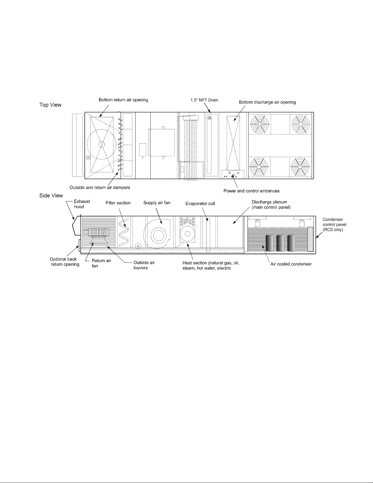
Unit Layout Diagrams
Unit Section
Unit Section Layout
1
1
The Unit Section Layout Diagrams shown above are to be used only for reference. Sections and Component locations
may vary depending on unit size, configuration, and options selected.
Rooftop Units: RPS/RFS/RCS 015- 042 "D" Rev. P 08/12 RPL 0700015000 / Page 13
Page 14
Unit Layout Diagrams
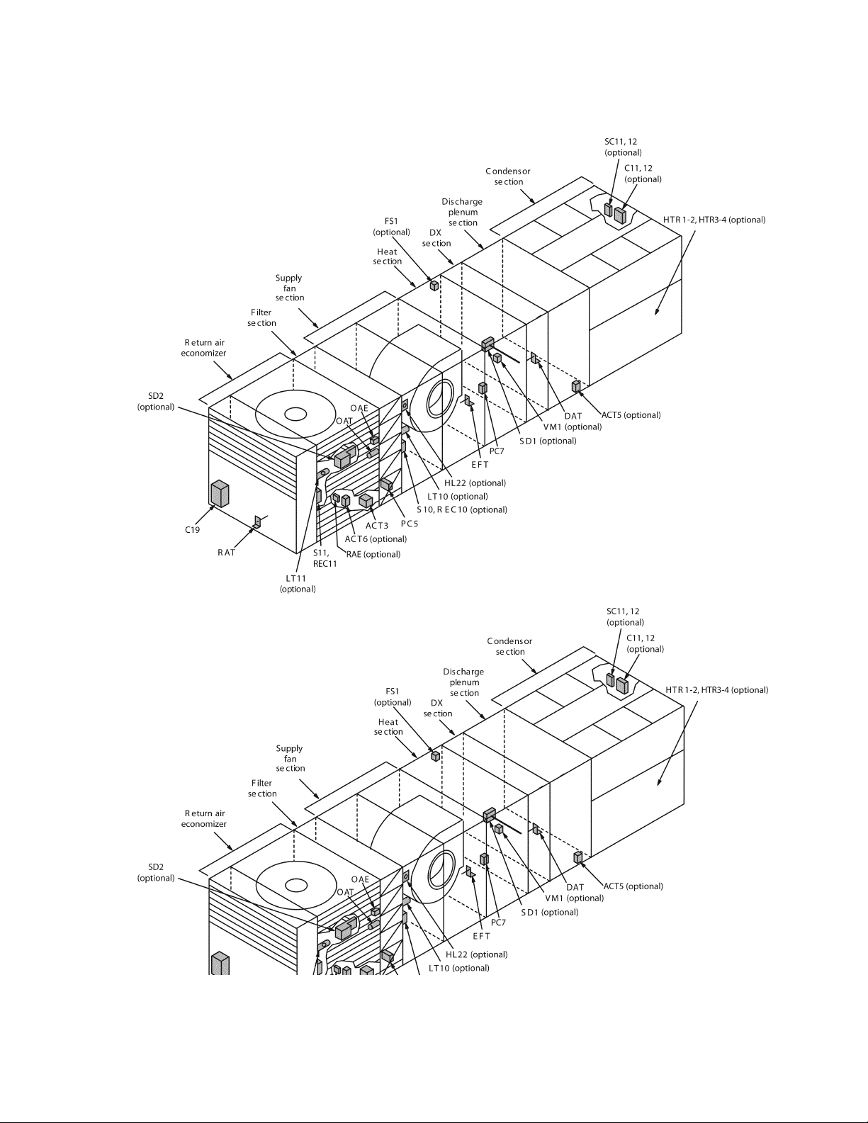
Control Location
1
1
RPS Unit shown for reference. Controls and locations may vary depending
on unit configuration and options selected.
Rooftop Units: RPS/RFS/RCS 015- 042 "D" Rev. P 08/12 RPL 0700015000 / Page 14
Page 15

Electrical Legend
Schematic Sym. Description Location
ACT3, 4 Actuator Motors, Economizer Economizer Section
ACT5 Actuator Motor, Discharge Isolation Damper Discharge Section
ACT6 Actuator Motor, Return Air Isolation Damper Return Air Section
ACT7 Actuator Motor, Heat Face/Bypass Coil Section, Heat
ACT8 Actuator Motor, Cool Face/Bypass Coil Section, Cool
ACT10, 11 Actuator Motors, Exhaust Dampers Return Air Section
ACT12, 13 Actuator Motor, Enthalpy Wheel Bypass Damper Energy Recovery Section
AS Airflow Switch, Burner Blower Gas Heat Box
BM Burner Blower Motor Furnace Section
C1 - C4 Power Factor Capacitors, Compressors Condenser Section
C10 Power Factor Capacitors, Supply Fan Supply Air Section
C20 Power Factor Capacitors, Return Fan Return Air Section
CB10 Circuit Breaker, Supply Fan Main Control Box
CB20 Circuit Breaker, Return/Exhaust Fan Main Control Box
CB60 Circuit Breaker, Energy Recovery Wheel Main Control Box
COMPR.1 - 4 Compressors Condenser Section
DAT Discharge Air Temperature Sensor Discharge section
DFLH Design Flow Sensor, Left Hand Return Section
DFRH Design Flow Sensor, Right Hand Return Section
DHL Duct High Limit Main Control Box
DS1 Disconnect, Total Unit or Condenser/Heat Main Control Box
DS2 Disconnect, SAF/RAF/Controls Main Control Box
DS3 Disconnect, Electric Heat Electric Heat Section
DS4 Disconnect, Condenser (RCS only) RCS Control Box
DS6 Disconnect, Factory Powered Outlet Condenser Section
EAT Exhaust Air Temperature Sensor Energy Recovery Section
EFT Entering Fan Air Temperature Sensor Supply Fan Section
ERM1, 2 Energy Recovery Wheel Motors Energy Recovery Section
EXPA, B, C Expansion Board Main Control Box
F1A, B Fuse, Control Circuit Transformer, (T1) Primary Main Control Box
F1C Fuse, Control Circuit Transformer, (T1) Secondary Main Control Box
F2 Fuse, Control Circuit Transformer, (T2) Primary Main Control Box
F3 Fuse, Burner Blower Motor Main Control Box
F6A, B Fuse, Transformer, (T6) Primary Condenser Section
F6C Fuse, Transformer, (T6) Secondary Condenser Section
FB11, 12 Fuseblocks, Speedtrol Main/Cond. Control Box
FB31 - 40 Fuseblocks, Electric Heat (Top Bank) Electric Heat Box
FB41-50 Fuseblocks, Electric Heat (Bottom Bank) Electric Heat Box
FD Flame Detector Furnace Section
FLC Fan Limit Control Furnace Section
FP1, 2 Frost Protection, Refrigeration Circuits Coil Section, Cool
FS1, 2 Freezestat Control Coil Section, Heat/Cool
FSG Flame Safeguard Gas Heat Box
GFR1, 2 Ground Fault Relay Main Control Box
GFS1, 2 Ground Fault Sensor Main Control Box
GFR4 Ground Fault Relay, Condenser Condenser Control Box
GFS4 Ground Fault Sensor, Condenser Condenser Control Box
GRD Ground All Control Boxes
GV1 Gas Valve, Pilot Furnace Section
GV2 Gas Valve, Main/Safety Furnace Section
GV3 Gas Valve, Redundant/Safety Furnace Section
GV4-8 Gas Valve, Main, Hi-Turn Down Furnace Section
HL 1-10 High Limits, Power, Electric Heaters (Top Bank) Electric Heat Section
Rooftop Units: RPS/RFS/RCS 015- 042 "D" Rev. P 08/12 RPL 0700015000 / Page 15
Page 16

Electrical Legend
Continued
Schematic Sym. Description Location
HL 11-20 High Limits, Power, Electric Heaters (Bottom Bank) Electric Heat Section
HL22 High Limit, Gas Heat (Prefilters) Supply Air Section
HL23 High Limit, Gas Heat (Final Filters) Final Filter Section
HL31-40 High Limits, Control, Electric Heaters (Top Bank) Electric Heat Section
HL41-50 High Limits, Control, Electric Heaters (Bottom Bank) Electric Heat Section
HP1-4 High Pressure Controls, Refrigerant Compr./Press./Cond. Box
HP5 High Pressure Control, Gas Furnace Section
HS1 Heat Switch, Electric Shutdown Main Control Box
HS3 Heat Switch, Electric Heat Deadfront Interlock Electric Heat Box
HTR1-4 Crankcase Heaters On Compressors
HUM1 Humidistat Sensor Energy Recovery Section
IT Ignition Transformer Furnace Section
LAT Temperature Sensor, Leaving Air Energy Recovery Section
LP1 - 4 Low Pressure Controls, Refrigerant On Compr./Cond. Box
LP5 Low Pressure Control, Gas Furnace Section
LR10 Line Reactor, Supply Fan Inverter Bypass Box
LR20 Line Reactor, Return/Exhaust Fan Inverter Bypass Box
LR11, 21 Line Reactor, Condenser Fan Speedtrol Pressure/Cond. Box
LS1, 2 Limit Switch, Low/High Fire Furnace Section
LT10 Light, Supply Fan Supply Air Section
LT11 Light, Return Fan Return Air Section
LT12 Light, Heat Section Heat Section
LT13 Light, Filter Section Filter Section
LT14 Light, Final Filter Section Final Filter Section
LT15 Light, Discharge Section Discharge Section
LT16 Light, Blow-through Coil Section Blow-thru Coil Section
LT17 Light, Evaporator Coil Section Evaporator Coil Section
LT18 Light, Preheat Section Preheat Section
LT19 Light, Blank Section Blank Section
LT20 Light, Blank Compartment Blank Compartment
LT21 Light, Draw Thru Coil Section Draw-thru Coil Section
LT22 Light, Condenser Section Condenser Section
M1-4 Contactors, Compressors Main/Cond. Control Box
M10 Contactor, Supply Fan Main Control Box
M11-18 Contactors, Condenser Fans, Circuit #1 Main/Cond. Control Box
M20 Contactor, Return Fan Main Control Box
M21-28 Contactors, Condenser Fans, Circuit #2 Main/Cond. Control Box
M29 Contactor, Burner Motor Furnace Section
M30 Contactor Reversing, Inverter Bypass, Supply Fan Inverter Bypass Box
M31-39 Contactors, Elec. Heaters (Top Bank) Electric Heat Section
M40 Contactor, Reversing, Inverter Bypass, Return Fan Inverter Bypass Box
M41-50 Contactors, Elec. Heaters (Bottom Bank) Electric Heat Section
M60, 61 Contactors, Energy Recovery Wheel Motor Main Control Box
MCB Microtech III Control Board Main Control Box
MJ Mechanical Jumpers All Control Boxes
MMP1-4 Manual Motor Protectors, Compressors Main/Cond. Control Box
MMP10 Manual Motor Protector, Supply Fan Main Control Box
MMP11 - 18 Manual Motor Protectors, Condenser Fans Ckt. 1 Main/Cond. Control Box
MMP20 Manual Motor Protector, Return fan Main Control Box
MMP21 - 28 Manual Motor Protectors, Condenser Fans Ckt. 2 Main/Cond. Control Box
MMP30 Manual Motor Protector, Inverter Bypass Supply Fan Inverter Bypass Box
Rooftop Units: RPS/RFS/RCS 015- 042 "D" Rev. P 08/12 RPL 0700015000 / Page 16
Page 17

Electrical Legend
Continued
Schematic Sym. Description Location
MMP40 Manual Motor Protector, Inverter Bypass Return Fan Inverter Bypass Box
MMP51 - 53 Manual Motor Protectors, Exhaust Fan(s) Prop Exhaust Box
MMP60 Manual Motor Protector, Energy Recovery Wheel Main Control Box
MP1-4 Motor Protectors, Compressors On Compressors
OAE Enthalpy Control, Outside Air Economizer Section
OAT Temperature Sensor, Outside Air Economizer Section
PB1, 2 Powerblock, Power Distribution Main Control Box
PB3 Powerblock, Power Distribution, Electric Heat Electric Heat Section
PB4 Powerblock, Power Distribution, Condenser Cond. Control Box
PB9, 10 Powerblock, Supply Fan Junction Box, Split Unit
PB11, 12 Powerblock, Power Distribution Main Control Box
PB19, 20 Powerblock, Return/Exhaust Fan Junction Box, Split Unit
PC5 Pressure Control, Clogged Filter Pre Filter Section
PC6 Pressure Control, Clogged Final Filter Final Filter Section
PC7 Pressure Control, Proof of Airflow Supply Air Section
PC13, 23 Pressure Control, FanTrol Pressure/Cond. Box
PT11, 21 Pressure Transducer, SpeedTrol Pressure/Cond. Box
PVM1, 2 Phase Voltage Monitor Main Control Box
PVM 4 Phase Voltage Monitor, Condenser Condenser Control Box
R1-2 Relay, High Pressure Reset (RCS only) RCS Control Box
R5-8 Relay, Safety (RCS only) RCS Control Box
R31-36 Relay, Compressor Staging (RCS only) RCS Control Box
R11 Relay, Cond. Fan 11 SpeedTrol Inverter Enable Pressure/Cond. Box
R12 - 14 Relays, FanTrol Condenser Fan Cycling Main/Cond. Control Box
R17 Relay, Cond. Fan 21 SpeedTrol Inverter Enable Pressure/Cond. Ctrl. Box
R20 Relay, Gas/Steam/Hot Water Furn./Main Ctrl. Box
R21, 22 Relays, Gas Heat, 20:1 High Turndown Furn./Main Ctrl. Box
R23 Relay, Gas Heat Furnace Section
R24 Relay, Gas Heat Alarm Main Control Box
R25 Relay, Gas Heat, Start Supply Fan Inverter Main Control Box
R26 Relay, Isolation/Exhaust Dampers Main Control Box
R28 Relay, Isolation Damper Safety Main Control Box
R45 Relay, UV Lights Main Control Box
RAE Enthalpy Sensor, Return Air Return Air Section
RAT Temperature Sensor, Return Air Return Air Section
REC1 Receptacle, Main Box Main Control Box
REC2 Receptacle, Condenser Box Cond. Control Box
REC3 Receptacle, Field Power, 115VAC Discharge Bulkhead
REC10-23 Receptacles, Cabinet Sections Cabinet Sections
S1 Switch, System On/Off Main Control Box
S2 Switch, System On/Off, RCS Unit Cond. Control Box
S3 Switch, Furnace On/Off Furnace Section
S4 Switch, Inverter Bypass On/Off Main Control Box
S40-45 Switches, Door Interlock, UV Lights Cabinet Sections
SC11 Speed Control, Circuit #1 Cond. Bulkhead
SC21 Speed Control, Circuit #2 Cond. Bulkhead
SD1 Smoke Detector, Supply Air Discharge Section
SD2 Smoke Detector, Return Air Return Air Section
SHS1 Sensor, Space Humidity Return Section (Field inst.)
SPS1, 2 Sensors, Static Pressure, Duct or Building Main Control Box
SV1,2 Solenoid Valves, Liquid/Drop Condenser Section
Rooftop Units: RPS/RFS/RCS 015- 042 "D" Rev. P 08/12 RPL 0700015000 / Page 17
Page 18

Electrical Legend
Continued
Schematic Sym. Description Location
T1 Transformer, Main Control, Line/115VAC Main Control Box
T2 Transformer, Control Input, 115/24VAC Main Control Box
T3 Transformer, Control Output, 115/24VAC Main Control Box
T6 Transformer, Factory Powered outlet, Line/115VAC Condenser Section
T11 Transformer, Speedtrol, Line/240VAC Condenser Section
TB1 Terminal Block, Internal for Transformers Main Control Box
TB2 Terminal Block, Field Main Control Box
TB3 Terminal Block, Factory, 115/24VAC Main Control Box
TB4 Terminal Block, Field, 115VAC Main Control Box
TB5 Terminal Block, RCS Field, 115V Condenser Control Box
TB6 Terminal Block, RCS Field Condenser Control Box
TB7 Terminal Block, 115VAC Convenience Outlet Main Control Box
TB8 Terminal Block, RCS, 115VAC Convenience Outlet Condenser Control Box
TB11 Terminal Block, Heating Furn./Elect. Heat Ctrl. Box
TB25 - 28 Terminal Blocks, Split Unit Junction Box Split Unit Junction Box
TC12 - 14 Temperature Controls, FanTrol Condenser Section
TD20 Time Delay, Return Air Fan Main Control Box
TR1, 2 Transducer, Pressure, SpeedTrol Main Control Box
UV Ultra-Violet Light(s) Coil/Discharge Section
VFD10 Adjustable Frequency Drive, Supply Fan Draw thru/Supply Section
VFD11, 21 Adjustable Frequency Drive, Cond. Fan SpeedTrol Pressure/Cond. Ctrl. Box
VFD20 Adjustable Frequency Drive, Return/Exhaust Fan Dr. Thru/Ret./Exh. Section
VFD60 Adjustable Frequency Drive, Energy Recovery Wheel Energy Recovery Section
VM1 Valve Motor #1, Heating Furnace/Heating Section
VM5 Valve Motor #5, Cooling Coil Section, Cooling
VV1 Vent Valve, Gas Heat Furnace Section
ZNT1 Sensor, Zone Temperature, Setback Field Installed
Rooftop Units: RPS/RFS/RCS 015- 042 "D" Rev. P 08/12 RPL 0700015000 / Page 18
Page 19

Section A1- Outdoor/Return Air Section
➩
Primary Codes that pertain: 19, 20, 21, 22, 23
Additional Codes that pertain: 06, 09, 12, 14, 15, 16, 17, 49
Codes 19 and 20 determine the base section. Code 19 is the Return Air Plenum and determines if the unit has
back (a.k.a. horizontal) return air or bottom return air. The plenum is required for any outdoor air application
with an economizer (Code 20= BE, BY, DE, DY, EE, EY, FE, FY, GE or GY). The only case in which a plenum
is not required is when a 100% outdoor air damper and hood are ordered (C20= AE, AY).
Codes 21, 22, 23 determine the return air fan, motor and drives. These codes only pertain to units with a 0-100%
economizer (C20= DE, DY, EE, EY, FE, FY, GE or GY). The fan section parts, the fans, and the motors are listed
in this section. The drive components (fan sheave, motor sheave, belt, and fan bushing) are not listed as
they are unique to the unit. If a drive component is required you may use the number from the part and
cross reference it with the Drive Components Cross Reference, or contact Daikin McQuay Parts with
model and serial number information for identification.
Code 06 determines the panels used in final cabinet assembly (return air units only).
Code 09, the voltage, is part of the motor part number identification.
Notes
Code 12, the control system, comes into play when an economizer is present. The economizer comes with an
actuator motor on a MicroTech unit, but may not have a motor if the unit has controls by others (C12= YM, YC).
Code 14 determines if the return fan has an inverter, or variable frequency drive (VFD).
Code 15 determines what type of inverter was ordered, or if the inverter was field installed and controlled by
the Microtech III controller.
Code 16 determines the smoke detector which is located in the return air cabinet. C16= 1 or 3 if a smoke detector
(SD2) is present.
Code 17 determines the type of Enthalpy and Miscellaneous Auxiliary Controls included. The second digit of
Code 17 lists the inclusion of Freezstats, Phase Failure, Line Reactors, and Ground Fault protection. See the
Unit Code Index section to determine which options were specified.
Code 49 determines if the return air cabinet has a light (C49= E), fan belt guards (C49= D) or both (C49= F).
Rooftop Units: RPS/RFS/RCS 015- 042 "D" Rev. P 08/12 RPL 0700015000 / Page 19
Page 20
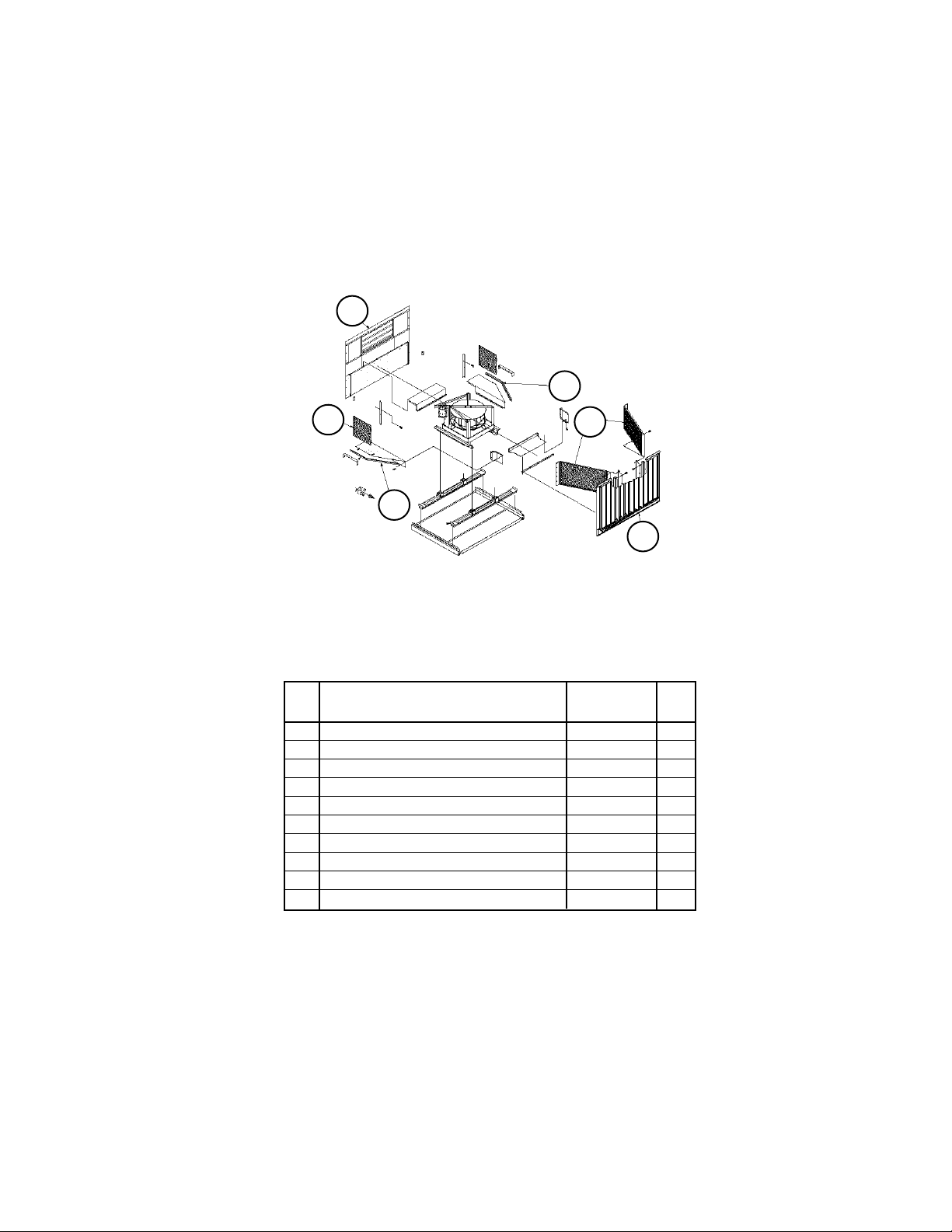
Section A1- Outdoor/Return Air Section
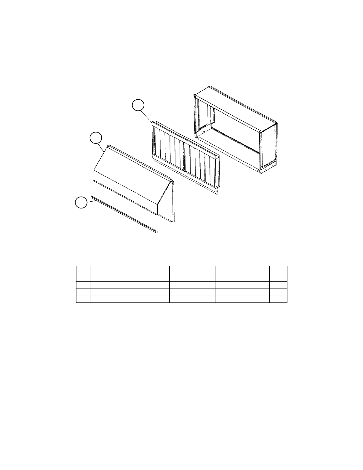
100% Outside Air Damper with Hood
C20= AE or AY and C19= YY
No Return Air Plenum
4
6
14
SectionB
100% Outdoor Air Damper w/ Hood (C20= AE, AY)
Ref Part With Actuator Without Actuator Qty.
No. Description C20= AE C20= AY
4 Damper Assembly 1 098313601 098313601 1
6 Hood 058440303 058440303 1
14 Channel 058436501 058436501 1
1
This damper assembly does not include an actuator or actuator linkage. A list of component parts
follows this page.
Note: The outdoor air damper with actuator (C20= AE) must have MicroTech III controls. Dampers
without actuators (C20= AY) must have controls by others (C12= YM, YC).
Rooftop Units: RPS/RFS/RCS 015- 042 "D" Rev. P 08/12 RPL 0700015000 / Page 20
Page 21
Section A1- Outdoor/Return Air Section
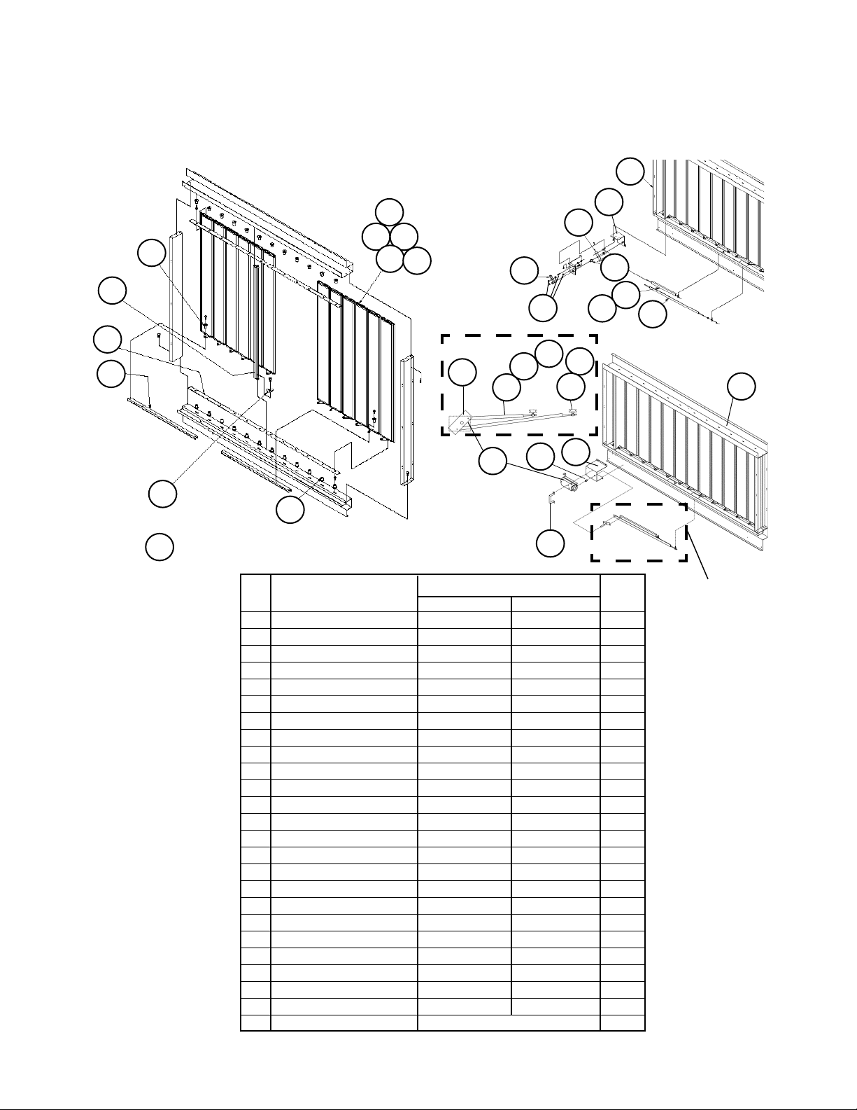
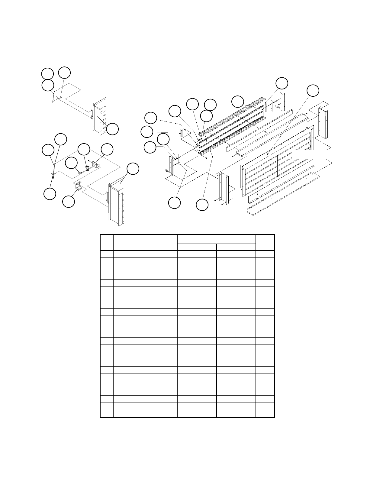
100% Outside Air Damper with Hood
C20= AE or AY and C19= YY
26
14
18
23
16
1
Damper Assy Detail
24
29
13 25
27
28
Manual
Linkage
Detail:
C20= AY
6
7
22
Motorized
Linkage
Detail:
C20= AE
20
21
38
31
38
35
6A
4
11
21
21
1
17
31A
7
4
1
Ref Part Actuator: ACT 3
No. Description C20= AE C20= AY Qty.
1 Damper Assy 098313601 098313601 1
4 Linkage Rod 067012700 067012700 1
6 Crank Arm Operator 066302059 Not used 1
6A Arm Shaft Not used 065371301 1
7 Linkage Rod 067012800 067012800 1
11 Actuator Support 403699401 not used 1
13 Damper Blade 044195101 044195101 12
14 Damper Seal 055616401 055616401 4
16 Damper Stop 065779801 065779801 2
17 Bearing Support Not used 066002401 1
18 Linkage Bar 047149800 047149800 2
20 Crank Arm Not used 025072600 1
21 Ball Joint 000887000 000887000 4
22 Actuator Motor: ACT3 113139501 Not used 1
23 Bushing 046098300 046098300 12
24 Bushing 043730400 043730400 24
25 Gasket 044193114 044193114 12
26 Gasket 045655714 046555714 1
27 Damper End Plug 041003501 041003501 12
28 Damper End Plug 041003502 041003502 6
29 Damper End Plug 041003503 041003503 6
31 Bearing 047138504 Not used 1
31A Lock Collar Not used 049115902 2
35 Retainer Bracket 403633801 Not used 1
38 Nut, Hex 040499904 040499904 4
See Detail above.
Rooftop Units: RPS/RFS/RCS 015- 042 "D" Rev. P 08/12 RPL 0700015000 / Page 21
Page 22
15
34
13A
Section A1- Outdoor/Return Air Section
0- 30% Outside Air Section Damper
C20= BE or BY and C19= BY or HY
14
Linkage
Detail:
Without
Actuator
C20= BY
31
33
42
10
8
30
26
15
36
34
13
48
35
1
14
43
1
Detail:
With
32
11
9
37
Linkage
Actuator
C20= BE
Ref Part Actuator: ACT 3
No. Description C20= BE C20= BY Qty.
Damper Assembly 1 403671301 058440322 1
1 Damper 2 098314101 098314101 1
8 Damper Blade 044193213 044193213 2
9 Gasket 055940213 055940213 1
10 Gasket 044193132 044193132 2
11 End Seal 058456701 058456701 2
13 Motor Support 058456501 Not used 1
13A Rod Support Angle Not used 055608601 1
14 Linkage Bar 058456601 058456601 1
15 Shaft Linkage 055536606 055536606 1
26 Exhaust Louver 096170531 096170531 1
N/S Screen Only 058434301 058434301 2
30 End Plug 041003505 041003505 2
31 End Plug 041003506 041003506 2
32 Bushing 043730400 043730400 4
33 Bushing 046098300 046098300 4
34 Ball Joint 000887000 000887000 2
35 Actuator Motor ACT3 113139501 Not used 1
36 Damper Crank Arm 403666401 Not used 1
37 Mounting Plate 403667001 Not used 1
42 Screw- .19-24 x .75 046093803 046093803 4
43 Screw- .25-20 x 1.00 046296600 046296600 4
48 Retainer 403633801 Not used 1
N/S= Not shown on diagram.
1
Assembly includes damper, damper linkage, and actuator (C20= BE) or damper
and linkage (C20= BY).
2
Damper only, no linkage or actuator components.
Damper Detail
Rooftop Units: RPS/RFS/RCS 015- 042 "D" Rev. P 08/12 RPL 0700015000 / Page 22
Page 23
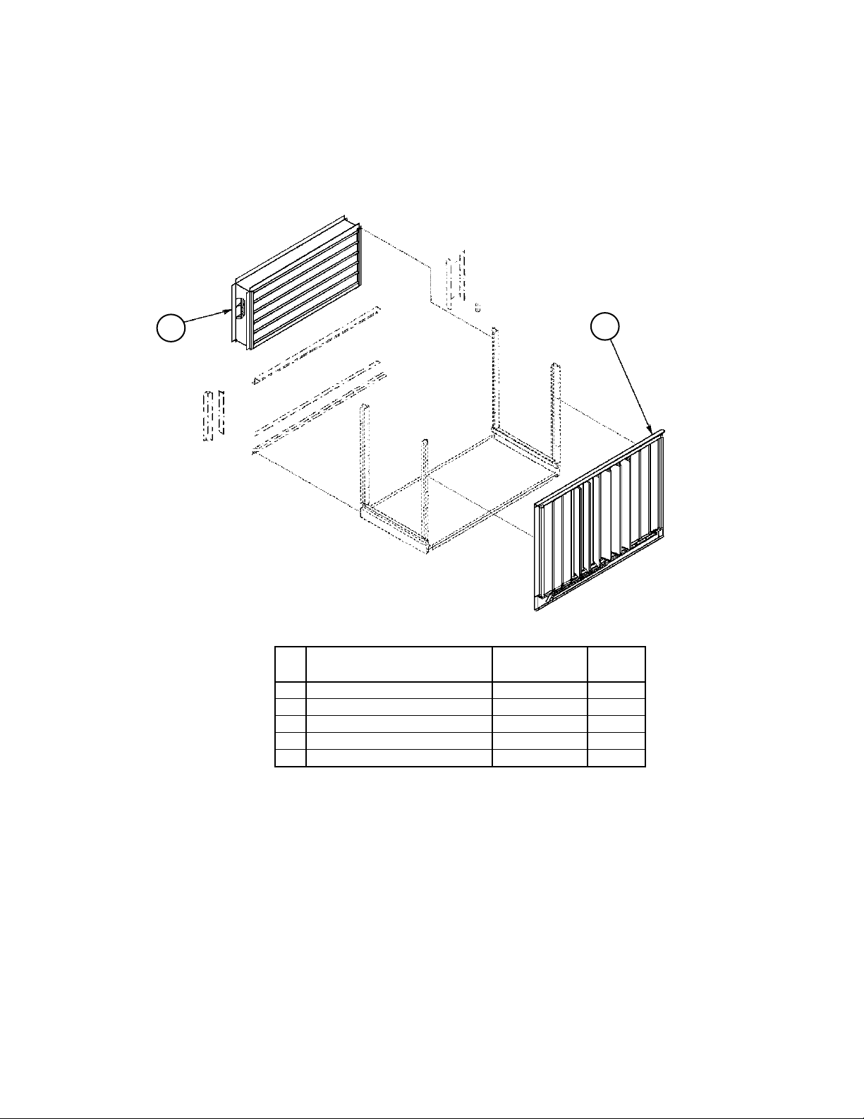
Section A1- Outdoor/Return Air Section
0- 100% Economizer Section with Barometric Exhaust Damper
Units without Return Air Fans
C20= DE, DY, EE, EY, FE, FY, GE, or GY, C21= YYYY
Back Return (C19= HY) shown.
12
11
Ref Part Part Qty.
No. Description Number
11 Economizer Damper 1 098312801 1
12 Exhaust Damper Assy 2 058440341 1
N/S Damper Only 030049300 1
N/S Exhaust Louver 096170531 1
N/S Louver Screen only 058434301 1
N/S= Not Shown on diagram.
1
This damper assembly does not include an actuator or actuator linkage.
A list of component parts is two pages previous to this page.
2
The Exhaust damper assembly includes the damper and side baffles.
Note: Economizer with actuator (C20= *E) requires MicroTech Controls.
Without actuator (C20= *Y), requires controls by others (C12= YM, YC).
Economizer detail follows four pages after next.
Rooftop Units: RPS/RFS/RCS 015- 042 "D" Rev. P 08/12 RPL 0700015000 / Page 23
Page 24
Section A1- Outdoor/Return Air Section
0 - 100% Economizer Section with Exhaust Damper
Units with 15" Forward Curved Return Air Fans
C20= DE, DY, EE, EY, FE, FY, GE, or GY, C21= 15**
Unit Sizes 015D- 030D only
54
125
12
55
150
11
124
Bottom Return (C19= BY or BB) shown.
Ref Part Part Qty.
No. Description Number
11 0- 100% Economizer Damper
1
098313601 1
Actuator/linkage Assy (C20= DE) 403696604 1
Linkage Assy w/o act. (C20= DY) 058400805 1
12 Damper Assy
Barometric (C20= DE,DY,FE,FY) 058440310 1
Power (C20= EE,EY,GE,GY) 058440320 1
Damper Only 112039627 1
54 Gasket 023530463 1
55 Gasket 023530416 2
124 Belt Guard- LH 2 058440381 1
125 Belt Guard- RH 2 058440382 1
150 Deflection Screen 046446600 1
1
This damper assembly does not include an actuator or actuator linkage. A list
of component parts is three pages previous to this page.
Note: Economizer with actuator (C20= DE) requires MicroTech Controls. Without actuator (C20= DY), requires controls by others. Economizer detail after
40" fan section detail.
2
Code 49= D or F.
Rooftop Units: RPS/RFS/RCS 015- 042 "D" Rev. P 08/12 RPL 0700015000 / Page 24
Page 25
Section A1- Outdoor/Return Air Section
0- 100% Economizer Section with Exhaust Damper
Units with 30" Air Foil Return Air Fans
C20= DE, DY, EE, EY, FE, FY, GE, GY and C21= 30**
12
55
50
55
11
Bottom Return (C19= BY or BB) shown.
Ref Part Part
No. Description Number Qty.
11 0- 100% Economizer Damper
1
098313601 1
Actuator/linkage Assy (C20= DE) 403696604 1
Linkage Assy w/o act. (C20= DY) 058400805 1
12 Damper Assy
Barometric (C20= DE,DY,FE,FY) 058440310 1
Power (C20= EE,EY,GE,GY) 058440320 1
Damper Only 112039627 1
50 Belt Guard 2 058400888 2
55 Gasket 055921422 2
1
This damper assembly does not include an actuator or actuator linkage.
A list of component parts is three pages previous to this page.
Note: Economizer with actuator (C20= DE) requires MicroTech Controls.
Without actuator (C20= DY), requires controls by others. Economizer
detail after 40" fan section detail.
2
Code 49= D or F.
Rooftop Units: RPS/RFS/RCS 015- 042 "D" Rev. P 08/12 RPL 0700015000 / Page 25
Page 26
Section A1- Outdoor/Return Air Section
0- 100% Economizer Section with Exhaust Damper
Units with 40" Air Foil Return Air Fans
C20= DE, DY, EE, EY, FE, FY, GE, GY and C21= 40**
Unit Sizes 035D thru 042D only
12
55
124
50
55
11
Bottom Return (C19= BY or BB)
is only option for 40" RAF.
Ref Part Part
No. Description Number Qty.
11 0- 100% Economizer Damper
1
098313601 1
Actuator/linkage Assy (C20= DE) 403696604 1
Linkage Assy w/o act. (C20= DY) 058400805 1
12 Damper Assy
Barometric (C20= DE,DY,FE,FY) 058440314 1
Power (C20= EE,EY,GE,GY) 058440324 1
Damper Only 112039627 1
50 Belt Guard 2 058400888 2
55 Gasket 055921422 2
124 Fan Guard 2 058440384 2
1
This damper assembly does not include an actuator or actuator linkage.
Note: Economizer with actuator (C20= DE) requires MicroTech Controls.
Without actuator (C20= DY), requires controls by others. Economizer
detail on next page.
2
Code 49= D or F.
Rooftop Units: RPS/RFS/RCS 015- 042 "D" Rev. P 08/12 RPL 0700015000 / Page 26
Page 27
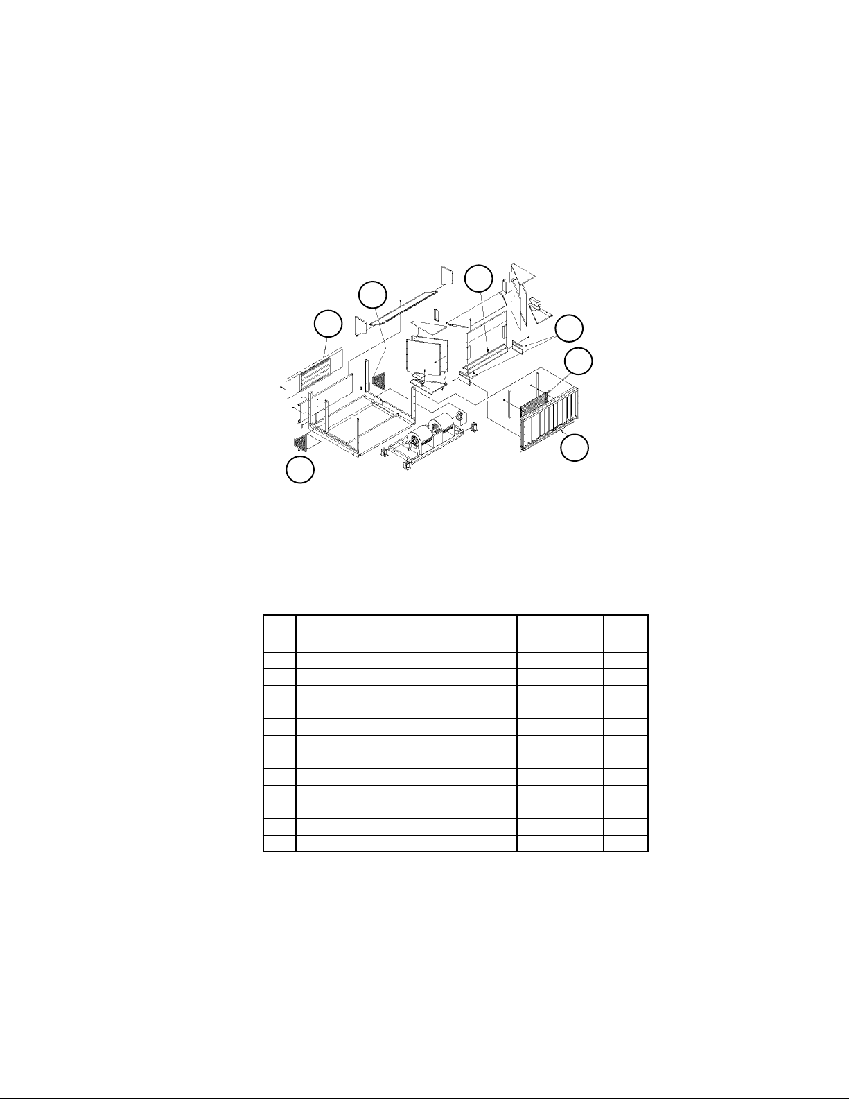
Section A1- Outdoor/Return Air Section
0- 100% Economizer Assembly
C20= D*, E*, F*, G*
10
9
14
12
3
26
23
Diagrams
13 25 27 28
29
11
22
18
With Actuator
C20= DE, EE, FE, GE
C12 must= *E or *F
31
21
6
7
19
35
21
15
16
12
19
24
8
Without Actuator
C20= DY, EY, FY, GY
C12 must= YM or YC
6A
31A
11A
19
4
20
17
421
721
Rooftop Units: RPS/RFS/RCS 015- 042 "D" Rev. P 08/12 RPL 0700015000 / Page 27
Page 28
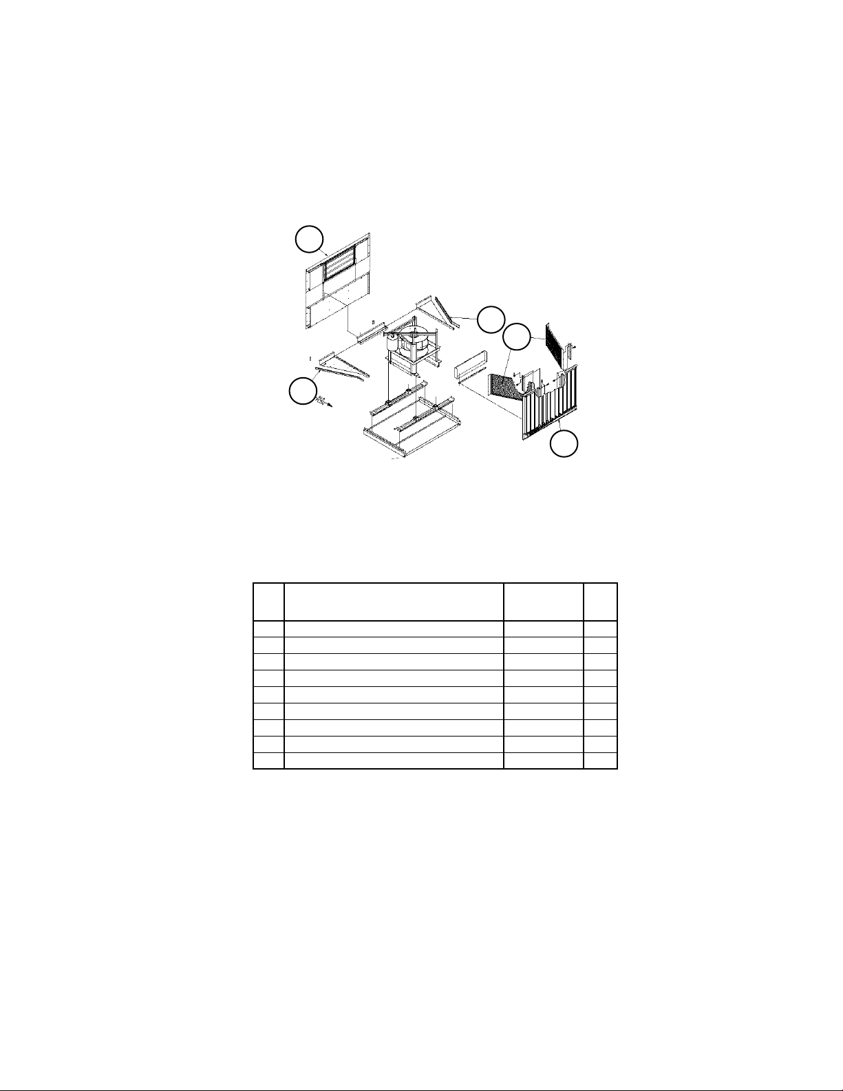
Section A1- Outdoor/Return Air Section
0- 100% Economizer Assembly
C20= DE, DY, EE, EY, FE, FY, GE, GY
Components
0-100% Economizer Detail
Ref Part
No. Description C20= DE C20= DY
Damper Assembly 1 098312801 098312801 1
3 Channel 058440313 058440313 1
4 Linkage Rod 112977101 067012700 1
6 Crank Arm Operator 066302059 Not used 1
6A Arm Shaft Not used 065371301 1
7 Linkage Rod 112977401 067012800 1
8 Bottom Support 058448201 058448201 1
9 Top Support 058448401 058448401 1
10 Block Off 058449601 058449601 1
11 Motor Mount 403633801 Not used 1
11A Rear Bearing Support Not used 066002101 1
12 Side Support 058448301 058448301 2
13 Damper Blade 044195101 044195101 12
14 Outside Seal 043734500 043734500 4
15 Center Seal 043734400 043734400 2
16 Damper Stop 065779801 065779801 4
17 Front Bearing Supp. Not used 066002201 1
18 Linkage Bar 044194800 044194800 2
19 Linkage Bar 044194900 044194900 2
20 Crank Arm Not used 025072600 1
21 Ball Joint 000887000 000887000 4
22 Actuator Motor, ACT4 113139601 Not Used 1
23 Bushing 046098300 046098300 12
24 Bushing 043730400 043730400 24
25 Gasket 044193114 044193114 12
26 Gasket 045655714 045655714 2
27 End Plug 041003501 041003501 12
28 End Plug 041003502 041003502 6
29 End Plug 041003503 041003503 6
31 Bearing 047138504 Not used 1
31A Locking Collar Not used 049115902 2
35 Mount 403634601 Not used 1
1
This damper assembly does not include an actuator or actuator linkage.
Actuator: ACT 4
Qty.
Rooftop Units: RPS/RFS/RCS 015- 042 "D" Rev. P 08/12 RPL 0700015000 / Page 28
Page 29
Section A1- Outdoor/Return Air Section
Return Air Plenum Isolation Damper w/ Actuator ACT6
C19= BE and C21= 15F*
Unit Sizes 015 thru 031
25
3
21
97
24
4
22
Damper Components
Ref Part Part Qty.
No. Description Number
97 Damper Assembly w/ACT6 403721701 1
3 Motor Mount 055913701 1
4 Damper Blade 403721201 5
18 Damper Linkage 055536606 1
20 Actuator Motor ACT6 113144901 1
21 Damper Shaft 403717101 1
22 Damper Ball Joint 000887000 2
24 Damper Blade Gasket 029870900
25 Support 403716801 1
26 Retainer 403717301 1
1
The damper gasket is sold by the foot. Order 6.66 feet per blade.
1
20
18
20
26
21
22
Rooftop Units: RPS/RFS/RCS 015- 042 "D" Rev. P 08/12 RPL 0700015000 / Page 29
Page 30
Section A1- Outdoor/Return Air Section
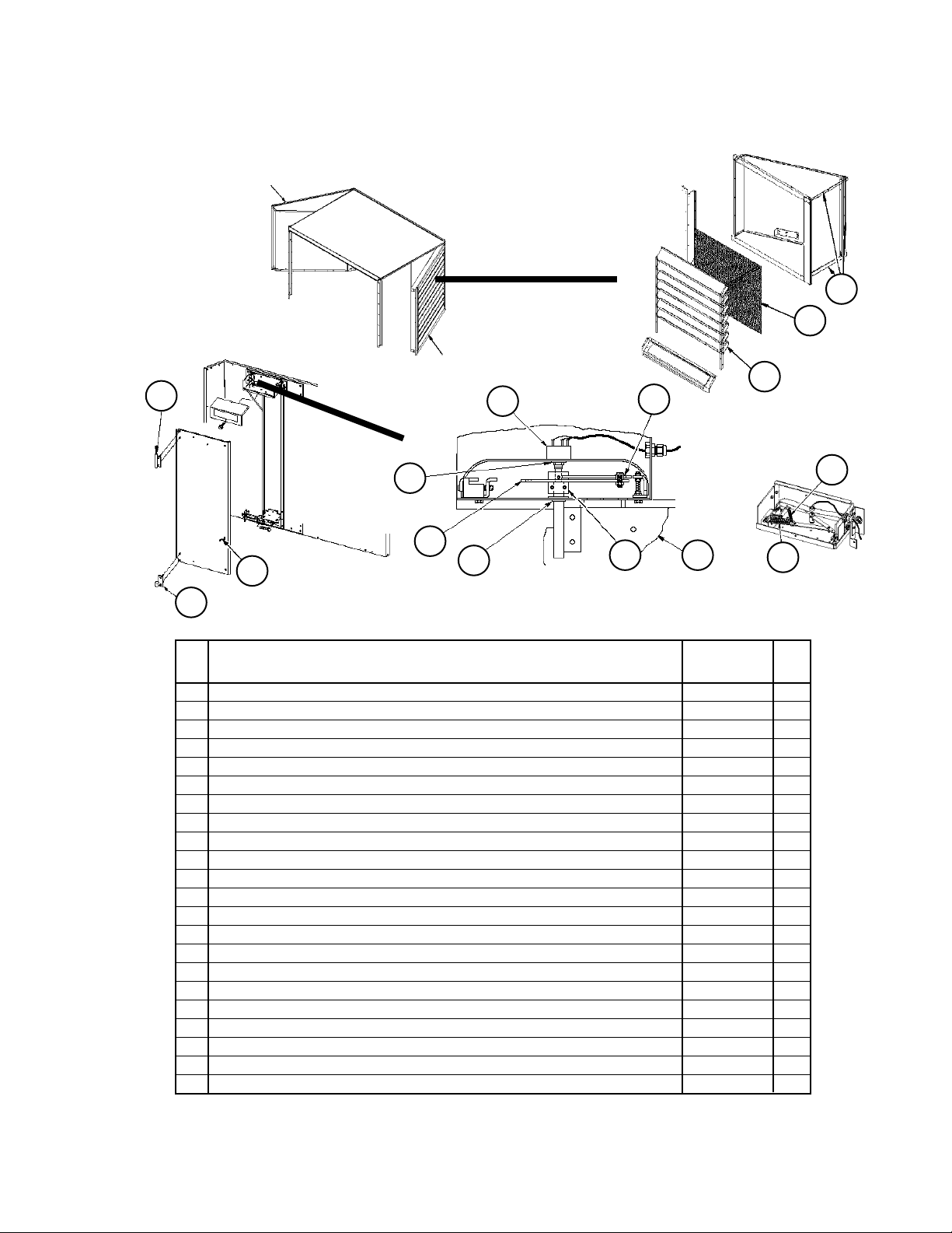
LH Louvered Door Assy
Section Final
Assembly
Design Flow
Code 20= FE, FY, GE, GY
Louvered Door
Assembly Detail
➤
3
2
RH Louvered Door Assy
105
9
127
➤
12
110
104
106
Design Flow Vane and
Vane Bearings Detail
Ref Part Part Qty.
No. Description Number
1 Louver Panel
Units with no Return Fan (40" Door) Left Hand Door 058410204 7
Units with no Return Fan (40" Door) Right Hand Door 058410203 7
Units with 30" or 40" Return Fan (52" Door) Left Hand Door 058410104 7
Units with 30" or 40" Return Fan (52" Door) Right Hand Door 058410103 7
2 Grille
Units with no Return Fan (40" Door) 058410401 1
Units with 30" or 40" Return Fan (52" Door) 058564001 1
3 Gasket 026172804 3
9 Potentiometer 098663701 1
12 O'Ring- Potentiometer 098663801 1
104 Panel- Vane 098661801 1
105 Shaft- Upper 098662601 1
106 Bearing- Lower 091634501 1
109 Crank Arm Assy Left Hand Door 091658802 1
Crank Arm Assy Right Hand Door 091658801 1
110 Link Arm
120 Bearing 060014201 1
127 Bearing 047138535 1
130 Spring- Main 098664801 1
131 Spring- Secondary 098664901 1
N/S Leveling Kit- Design Flow 091659301 1
2
P/N is unit specific. Contact Daikin McQuay Parts with overall length and bolt hole spacing so that the correct part
can be identified.
120
Adjuster Control Assy
Detail
109 104
1
1
1
131
130
Spring
Detail
Rooftop Units: RPS/RFS/RCS 015- 042 "D" Rev. P 08/12 RPL 0700015000 / Page 30
Page 31

89
81
63
64
92
89
88
Pos. 2
Section A1- Outdoor/Return Air Section
Return Air Fan Mounting- 15" Forward Curved Fan
Code 21= 15F1, 15F2, 15F3
91
Rubber-In-Shear (RIS) Mount Code 21= 15F1
Ref Part Part Qty.
No. Description Number
21 Support Mount 055512101 1
61 Isolator R- 3 Black 021639704 1
81 Clinch Nut 059992201 2
89 Screw 112047201 2
91 Nut 032333305 3
92 Screw 040499501 2
1
Drawing is common to all four corners. Quantities listed are for ONE mount.
Ref Part Part Qty.
No. Description Number
21 Spring Mount- Standard 251783201 1
Spring Mount- Seismic 251783301 1
61 Spring Isolator- Position 3 Standard
Motor H.P.= 1 thru 3 251784501 1
Motor H.P.= 5 thru 7.5 251784701 1
Motor H.P.= 10 251784601 1
Spring Isolator- Position 3 Seismic
Motor H.P.= 1 thru 3 251784501 1
Motor H.P.= 5 thru 7.5 251784601 1
Motor H.P.= 10 251784701 1
62 Spring Isolator- Position 4 Standard
Motor H.P.= All 251784501 1
Spring Isolator- Position 4 Seismic
Motor H.P.= All 251784501 1
63 Spring Isolator- Position 2 Standard
Motor H.P.= 1 thru 3 251784601 1
Motor H.P.= 5 thru 7.5 251784801 1
Motor H.P.= 10 251784701 1
Spring Isolator- Position 2 Seismic
➤
Motor H.P.= 1 thru 3 251784601 1
Motor H.P.= 5 thru 7.5 251784701 1
Motor H.P.= 10 251784801 1
64 Spring Isolator- Position 1 Standard
Motor H.P.= All 251784601 1
Spring Isolator- Position 1 Seismic
Motor H.P.= All 251784601 1
81 Clinch Nut- Standard 059992201 3
Clinch Nut- Seismic 111056301 5
88 Nut 040500002 1
89 Screw- Standard 112047201 3
Screw- Seismic 112047201 5
2
Drawing is common to all four corners. Quantities listed are for ONE mount.
3
This part is used only when Code 21= 15F3.
81
Top View
61
21
91
Spring Mount Code 21= 15F2 and Seismic Mount Code 21= 15F3
21
Typical. Seismic strap
used only when Code
21= 15F3.
62
61
64
63
Pos. 3
61
Air Flow
Pos. 4Pos. 1
62
1
2
3
3
3
Rooftop Units: RPS/RFS/RCS 015- 042 "D" Rev. P 08/12 RPL 0700015000 / Page 31
Page 32

93
92
89
Section A1- Outdoor/Return Air Section
Return Air Fan Mounting- 30" and 40" Airfoil Fan
Code 21= 30B1, 40B1, 30B2, 40B2, 30B3, 40B3
91
Rubber-In-Shear (RIS) Mount Code 21= 30B1, 40B1
61
21
91
81
Ref Part Part Qty.
No. Description Number
21 Support Mount 055512101 1
61 Isolator R- 3 Black 021639704 1
81 Clinch Nut 059992201 2
89 Screw 112047201 2
91 Nut 032333305 3
92 Screw 040499501 2
93 Washer 040500310 2
1
Drawing is common to all four corners. Quantities listed are for ONE mount.
1
Spring Mount Code 21= 30B2, 40B2 and Seismic Mount Code 21= 30B3, 40B3
Diagram
88
21
89
Typical. Seismic strap
used only when Code
21= ***3.
62
61
61
63
64
Pos. 3
Air Flow
➤
81
63
Pos. 2
Top View
Pos. 4Pos. 1
64
Rooftop Units: RPS/RFS/RCS 015- 042 "D" Rev. P 08/12 RPL 0700015000 / Page 32
62
Page 33

Section A1- Outdoor/Return Air Section
Return Air Fan Mounting- 30" and 40" Airfoil Fan
Code 21= 30B2, 30B3
Spring Mounting Code 21= 30B2, and Seismic Mount Code 21= 30B3
Components
Ref Part 30" Qty.
No. Description Fan
21 Spring Mount- Standard 251783201 1
Spring Mount- Seismic 251783301 1
2
61 Spring Isolator- Position 3 Standard
Motor H.P.= 1 thru 3 251784601 1
Motor H.P.= 5 thru 10 251784701 1
Spring Isolator- Position 3 Seismic
Motor H.P.= 1 thru 3 251784601 1
Motor H.P.= 5 thru 10 251784701 1
62 Spring Isolator- Position 4 Standard
Motor H.P.= All 251784401 1
Spring Isolator- Position 4 Seismic
Motor H.P.= All 251784401 1
63 Spring Isolator- Position 2 Standard
Motor H.P.= 1 thru 5 251784601 1
Motor H.P.= 7.5 thru 10 251784701 1
Spring Isolator- Position 2 Seismic
Motor H.P.= 1 thru 7.5 251784601 1
Motor H.P.= 10 251784701 1
64 Spring Isolator- Position 1 Standard
Motor H.P.= All 251784401 1
Spring Isolator- Position 1 Seismic
Motor H.P.= All 251784401 1
81 Clinch Nut- Standard 059992201 3
Clinch Nut- Seismic 111056301 5
2
88 Nut 040500002 1
89 Screw- Standard 112047201 3
Screw- Seismic 112047201 5
1
Quantity shown is for ONE mount.
2
This part is used only when Code 21= 30B3.
2
1
Rooftop Units: RPS/RFS/RCS 015- 042 "D" Rev. P 08/12 RPL 0700015000 / Page 33
Page 34

Section A1- Outdoor/Return Air Section
Return Air Fan Mounting- 30" and 40" Airfoil Fan
Code 21= 40B2, 40B3
Spring Mounting Code 21= 40B2, and Seismic Mount Code 21= 40B3
Components
Ref Part 40" Qty.
No. Description Fan
21 Spring Mount- Standard 251783201 1
Spring Mount- Seismic 251783301 1
2
61 Spring Isolator- Position 3 Standard
Motor H.P.= 1 thru 5 251784701 1
Motor H.P.= 7.5 thru 10 251784801 1
Spring Isolator- Position 3 Seismic
Motor H.P.= 1 thru 5 251784701 1
Motor H.P.= 7.5 thru 10 251784801 1
62 Spring Isolator- Position 4 Standard
Motor H.P.= 1 thru 5 251784501 1
Motor H.P.= 7.5 thru 10 251784601 1
Spring Isolator- Position 3 Seismic
Motor H.P.= 1 thru 5 251784501 1
Motor H.P.= 7.5 thru 10 251784601 1
63 Spring Isolator- Position 2 Standard
Motor H.P.= 1 thru 5 251784601 1
Motor H.P.= 7.5 thru 10 251784701 1
Spring Isolator- Position 2 Seismic
Motor H.P.= 1 thru 5 251784601 1
Motor H.P.= 7.5 thru 10 251784701 1
64 Spring Isolator- Position 1 Standard
Motor H.P.= All 251784501 1
Spring Isolator- Position 1 Seismic
Motor H.P.= All 251784501 1
81 Clinch Nut- Standard 059992201 3
Clinch Nut- Seismic 111056301 5
2
88 Nut 040500002 1
89 Screw- Standard 112047201 3
Screw- Seismic 112047201 5
1
Quantity shown is for ONE mount.
2
This part is used only when Code 21= 40B3.
2
1
Rooftop Units: RPS/RFS/RCS 015- 042 "D" Rev. P 08/12 RPL 0700015000 / Page 34
Page 35

Section A1- Outdoor/Return Air Section
Return Air Fan Deck
15" Fans: C21= 15F1, 15F2, 15F3
End View
27
15
Motor
13
1
18
20
21
7
6
8
15
26
15
20
13
Discharge View
1916
Ref Part Part
No. Description Number Qty.
6 Wheel 033135100 2
7 Motor Shelf 033262600 1
8 Filler Piece 033262400 1
13 Shaft 033262001 1
15 Tube Coupling 027674000 3
16 Tube Coupling Reducer 027674100 3
18 Tube Clamp 001324600 4
19 Grease Fitting 000109800 1
20 Ball Bearing 020648651 3
21 Shim
2
3
26 Key 023221409 2
27 Key 023221405 1
1
Motors are listed on a separate page after the fan deck details.
2
Shims are used as needed. Any of the following may be used: 025639900
(.058"); 091531301 (.046"); 091531601 (0.22"); 091531501 (.031").
Rooftop Units: RPS/RFS/RCS 015- 042 "D" Rev. P 08/12 RPL 0700015000 / Page 35
Page 36

Section A1- Outdoor/Return Air Section
Return Air Fan Deck
30" Fans: C21= 30B1, 30B2, 30B3
1
19A
1719
13
2627
6
2
Motor
7
1
17 1
19
Ref Part Part Qty.
No. Description Number
1 Bearing 020648651 2
2 Funnel- Inlet 031940902 1
6 Wheel- Fan 066543221 1
7 Mount- Motor 058400974 1
13 Shaft- Fan 058568201 1
17 Tubing- Plastic 021136745 2
19 Fitting- Grease 000109800 2
19A Fitting- Reducer 027674100 2
26 Key 023221405 1
27 Key 023221411 1
1
Motors are listed on a separate page after the fan deck details.
Rooftop Units: RPS/RFS/RCS 015- 042 "D" Rev. P 08/12 RPL 0700015000 / Page 36
Page 37

Section A1- Outdoor/Return Air Section
Return Air Fan Deck
40" Fans: C21= 40B1, 40B2, 40B3
17
27
6
26
1516
21
20
9
13
20
5
17
19
21
19
10
4
Motor
7
2
1
1516
Ref Part Part Qty.
No. Description Number
2 Inlet Funnel 031940905 1
4 Bearing Support 058400982 1
5 Lower Bearing Support 058400983 1
6 Fan Wheel: SISW 066543242 1
7 Fan Motor Mount 058400974 1
9 Baffle 055963002 1
10 Support 056197201 1
13 Shaft 037788701 1
15 Coupling 021213700 2
16 Coupling 027674100 2
17 Plastic tubing 021136745 2
19 Grease Fitting 000109800 2
20 Bearing 020648653 2
21 Shim 021494400 2
26 Shaft Key 023221508 1
27 Shaft Key 023221507 1
1
Motors are listed on a separate page after the fan deck details.
Rooftop Units: RPS/RFS/RCS 015- 042 "D" Rev. P 08/12 RPL 0700015000 / Page 37
Page 38

Section A1- Outdoor/Return Air Section
Return Air Fan Motors, Motor Mounts
H.P. Unit ODP HiEff ODP PrEff. TEFC HiEff TEFC PrEff Motor
Voltage C22= *EY C22= *JY C22= *HY C22= *KY Mount
C09= 12
1 208/60/3 039447400 205167600 049100100 004735000 073316603
1.5 208/60/3 039442200 205167500 049100200 046513100 073316604
2 208/60/3 039895700 046515500 049100300 073321000 073316604
3 208/60/3 039447500 065817100 047358100 065819400 073316605
5 208/60/3 039447600 065817200 049186800 065819500 073316606
7.5 208/60/3 037530300 065817300 047665900 065819600 073316607
10 208/60/3 038999000 065817400 047666100 065819700 073316608
C09= 29
1 230/60/3 039446200 205162800 040161000 046513000 073316603
1.5 230/60/3 039442300 046511100 040161100 046513100 073316604
2 230/60/3 039446300 205163500 047446000 073321000 073316604
3 230/60/3 039442400 065818100 049262300 065820100 073316605
5 230/60/3 039442500 065818200 040161200 065820200 073316606
7.5 230/60/3 039448700 065818300 049100500 065820300 073316607
10 230/60/3 039446500 065818400 044691100 065820400 073316608
C09= 27
1 460/60/3 039446200 205162800 040161000 046513000 073316603
1.5 460/60/3 039442300 046511100 040161100 046513100 073316604
2 460/60/3 039446300 205163500 047446000 073321000 073316604
3 460/60/3 039442400 065818100 049262300 065820100 073316605
5 460/60/3 039442500 065818200 040161200 065820200 073316606
7.5 460/60/3 039448700 065818300 049100500 065820300 073316607
10 460/60/3 039446500 065818400 044691100 065820400 073316608
C09= 37
1 575/60/3 049180800 206500900 049188000 206505600 073316603
1.5 575/60/3 049180900 206501600 049188100 205167800 073316604
2 575/60/3 049181000 205168300 049188200 046514400 073316604
3 575/60/3 046741600 046511700 049188300 046514500 073316605
5 575/60/3 046741900 205168900 049188400 046514600 073316606
7.5 575/60/3 047443300 205168800 049188500 046514700 073316607
10 575/60/3 047443400 205168600 049188600 065821400 073316608
Rooftop Units: RPS/RFS/RCS 015- 042 "D" Rev. P 08/12 RPL 0700015000 / Page 38
Page 39

Section A1- Outdoor/Return Air Section
Section Mounted Controls
OAE, RAE, LT11, S11, REC11
Bottom Return
Shown
C19= BY or BE
Economizer
Bottom Return
Shown
C19= BY or BE
Economizer
4342
40
40
41
41
OAE- Mechanical Enthalpy (Code 17= Y*)
Ref Part Part
No. Description Number Qty.
40 Mount- OAE Enthalpy 055800101 1
41 Enthalpy Assembly
(knob & Control) 055740691 1
Knob only 026215500 1
Control OAE only 030706702 1
OAE & RAE Differential Enthalpy (Code 17= C*)
Ref Part Part
No. Description Number Qty.
40 Mount- OAE Enthalpy 059328901 1
41 Control- OAE 049262201 1
42 Mount- RAE Enthalpy
Back Air Return 055800501 1
Bottom Air Return 055732301 1
43 Control- RAE 049262202 1
RAT- Return Air Temperature Sensor
30
Back Return
C19= HY
7
Return Air Opening
84 85
88 89
30
Return Air
Opening
Bottom Return
C19= BY or BE
Ref Part Part
No. Description Number Qty.
7 Sensor- RAT 193414602 1
SD2- Return Air Smoke Detector
C16= 1 or 3
Ref Part Part
No. Description Number Qty.
30 Smoke Detector SD2 098873101 1
LT11- Return Fan Light/S11- Return Fan Light
Switch/ REC11- Return Fan Light Receptacle
C49= E or F
Ref Part Part
No. Description Number Qty.
84 Light Fixture 042229500 1
85 Bulb- LT11 065492402 1
88 Light Switch- S11 065492201 1
89 Receptacle- REC11 030187000 1
Rooftop Units: RPS/RFS/RCS 015- 042 "D" Rev. P 08/12 RPL 0700015000 / Page 39
Page 40

Section A2- Outdoor/Return/Heat Recovery Air Section
➩
Primary Codes that pertain: 19, 20, 21, 22, 23, 24
Additional Codes that pertain: 06, 09, 14, 15, 16, 17, 49
Codes 19 and 20 determine the base section. Code 19 is the Return Air Plenum, and is always BY (bottom
return air). Code 20 determines the type of Outdoor Air/Heat Recovery control used. C20= 1E or 2E are 100%
OA Air units, and if C20= 3E the unit has an economizer.
Codes 21, 22, 23 determine the return air fan, motor and drives. The fan section parts, the fans, and the motors
are listed in this section. The drive components (fan sheave, motor sheave, belt, and fan bushing) are not
listed as they are unique to the unit. If a drive component is required you may use the number from the
part and cross reference it with the Drive Components Cross Reference, or contact Daikin McQuay Parts
with model and serial number information for identification.
Code 24 determines if the Heat Wheel has a frost protection inverter.
Code 06 determines the panels used in final cabinet assembly.
Code 09, the voltage, is part of the motor part number identification.
Notes
Codes 14 & 15 determine if the unit has inverter(s) and if so where they are installed. If Code 14= 3, 5, 6, 7,
8 or 9, the inverter(s) are installed in the Supply Air Section. If Code 14= 1, 2 or 4 AND Code 26= S, there is
a separate inverter section. If Code 14= Y, there are no inverters. Code 15 determines the inverter type. For
inverter information, refer to Section F the Supply Air Section.
Code 16 determines the smoke detector which is located in the return air cabinet. C16= 1 or 3 if a smoke detector
(SD2) is present.
Code 17 determines the type of Enthalpy and Miscellaneous Auxiliary Controls included. If Code 17=C*, the
unit is equipped with Differential Enthalpy Control. The second digit of Code 17 lists the inclusion of Freezstats,
Phase Failure, Line Reactors, and Ground Fault protection.
Code 49 determines if the return air cabinet has a belt guard (Code 49=D), or a belt guard and a fan section
light (Code 49=F).
Rooftop Units: RPS/RFS/RCS 015- 042 "D" Rev. P 08/12 RPL 0700015000 / Page 40
Page 41

Section A2- Outdoor/Return/Heat Recovery Air Section
100% Outside Air Low Flow - C20=1E
Intake Hood (see detail to left)
140
148
148
160
142
144
145
146
141
Outdoor Air Intake Hood
Detail
or
419418
LH
RH
422
Exhaust Hood
Detail
Ref Part Part
No. Description Number Qty.
1 Fan Assembly 1
12 Damper Assy- Low Leak 2 110905009 1
140 Panel, Top- Hood 111066001 1
141 Panel, LH Side- Outdoor Air Intake Hood 111066101 1
142 Panel, RH Side- Outdoor Air Intake Hood 111066601 1
144 Panel, Louver- Outdoor Air Intake Hood 111066301 1
145 Panel, Louver- Outdoor Air Intake Hood 111066401 1
146 Panel, Lower Louver- Outdoor Air Intake Hood 111066501 1
148 Screen- Outdoor Air Intake Hood 111076501 2
155 Gasket 024476500 8 ft.
160 Wheel, Enthalpy- Heat Recovery
161 Motor- Enthalpy Wheel
162 Sheave- Fixed
201 Filter Rack 110907301 1
202 Filter Rack 110907302 1
204 Filter Rack 110907304 1
206 Filter Rack 110907306 1
418 Door, Indented- Exhaust LH 111201841 1
419 Door, Indented- Exhaust RH 111201842 1
422 Exhaust Hood 111069501 2
N/S Filter 16 x 20 x 2 031298001 12
N/S Filter 16 x 25 x 2 031298002 12
N/S= Not Shown on Diagram.
1
See Detail two pages after next.
2
See Detail four pages after next.
3
See Detail in this section (A2) titled "Heat Recovery-Enthalpy-Wheel Detail (Ref #160) Wheel Motor,
Drive Components, Seals"
12
1
201
202
206
3
161
162
204
1
3
1
3
1
155
Rooftop Units: RPS/RFS/RCS 015- 042 "D" Rev. P 08/12 RPL 0700015000 / Page 41
Page 42

Section A2- Outdoor/Return/Heat Recovery Air Section
100% Outside Air High Flow - C20=2E
140
Hood (see detail to left)
148
148
142
144
145
146
141
Outdoor Air Intake Hood
Detail
or
419418
LH
RH
422
Exhaust Hood
Detail
Ref Part Part
No. Description Number Qty.
1 Fan Assembly 1
12 Damper Assy- Low Leak 2 110905009 1
140 Panel, Top- Hood 111066001 1
141 Panel, LH Side- Outdoor Air Intake Hood 111066101 1
142 Panel, RH Side- Outdoor Air Intake Hood 111066601 1
144 Panel, Louver- Outdoor Air Intake Hood 111066301 1
145 Panel, Louver- Outdoor Air Intake Hood 111066401 1
146 Panel, Lower Louver- Outdoor Air Intake Hood 111066501 1
148 Screen- Outdoor Air Intake Hood 111076501 2
155 Gasket 024476500 14 ft.
160 Wheel, Enthalpy- Heat Recovery
161 Motor- Enthalpy Wheel
162 Sheave- Fixed
201 Filter Rack 110907301 1
202 Filter Rack 110907302 1
203 Filter Rack 110907303 1
204 Filter Rack 110907304 1
418 Door, Indented- Exhaust LH 111201841 1
419 Door, Indented- Exhaust RH 111201842 1
422 Exhaust Hood 111069501 2
N/S Filter 16 x 20 x 2 031298001 12
N/S Filter 16 x 25 x 2 031298002 12
N/S= Not Shown on Diagram.
1
See Detail one page after next.
2
See Detail four pages after next.
3
See Detail in this section (A2) titled 'Heat Recovery-Enthalpy-Wheel Detail (Ref #160) Wheel Motor,
Drive Components, Seals".
155
160
201
202
1
161
12
162
204
203
3
2
3
2
3
2
Rooftop Units: RPS/RFS/RCS 015- 042 "D" Rev. P 08/12 RPL 0700015000 / Page 42
Page 43

Section A2- Outdoor/Return/Heat Recovery Air Section
Economizer - C20=3E
Outdoor Air
Intake Hood
Detail
142
Exhaust Hood
Detail
or
419418
LH
RH
422
Ref Part Part
No. Description Number Qty.
1 Fan Assembly 1
12 Damper Assy- Low Leak 2 Outdoor Air (w/ACT3) 110905009 1
12A Damper Assy- Low Leak 2 Return Air (w/ACT4) 110905009 1
140 Panel, Top- Hood 111066001 1
141 Panel, LH Side- Outdoor Air Intake Hood 111066101 1
142 Panel, RH Side- Outdoor Air Intake Hood 111066601 1
144 Panel, Louver- Outdoor Air Intake Hood 111066301 1
145 Panel, Louver- Outdoor Air Intake Hood 111066401 1
146 Panel, Lower Louver- Outdoor Air Intake Hood 111066501 1
148 Screen- Outdoor Air Intake Hood 111076501 2
155 Gasket 024476500 8 ft.
160 Wheel, Enthalpy- Heat Recovery
161 Motor- Enthalpy Wheel
162 Sheave- Fixed
201 Filter Rack 110907301 1
202 Filter Rack 110907302 1
204 Filter Rack 110907304 1
205 Filter Rack 110907305 1
230 Damper Assy- Bypass 4 110919907 1
418 Door, Indented- Exhaust LH 111201841 1
419 Door, Indented- Exhaust RH 111201842 1
422 Exhaust Hood 111069501 2
N/S Filter 16 x 20 x 2 031298001 12
N/S Filter 16 x 25 x 2 031298002 12
N/S= Not Shown on Diagram.
1
See Detail on next page.
2
See Detail two pages after next.
3
See Detail in this section (A2) titled "Heat Recovery-Enthalpy-Wheel Detail (Ref #160) Wheel Motor,
Drive Components, Seals".
4
See Detail three pages after next.
140
144
145
146
148
141
Intake Hood
148
1
12
202
201
205
204
230
160
12A
3
1
3
1
3
1
155
161
162
Rooftop Units: RPS/RFS/RCS 015- 042 "D" Rev. P 08/12 RPL 0700015000 / Page 43
Page 44

Section A2- Outdoor/Return/Heat Recovery Air Section
24" Return Fan Detail
10A
Fan Assy, Motor and
Motor Mounting
10
10B
Thrust Restraint Detail
7
10C
40
1
2
Ref Part Part
No. Description Number Qty.
1 Motor- Return Fan
2 Mount- Motor
1
1
7 Gasket 240488213 1
10 Fan Wheel and Housing Assembly 209989901 1
10A Shaft Only 010288108 1
10B Bearing Only 020648652 1
10C Wheel Only 010255211 1
40 Angle- Thrust Restraint 110916701 2
41 Spring Mount, Floor- Thrust Restraint Red 175 lb. 059397901 2
N/S Spring Mount- Screw 046093820 4
N/S= Not shown on diagram.
1
See Return Fan Motor Table for p/ns.
2
Two screws are required per mount.
41
2
Rooftop Units: RPS/RFS/RCS 015- 042 "D" Rev. P 08/12 RPL 0700015000 / Page 44
Page 45

Section A2- Outdoor/Return/Heat Recovery Air Section
24" Return Fan Detail
Fan Mounts
35B35C
Fan Mounting Locations
Top View
35D 35A
81
84
35A 35B 35C 35D
226
504
762
Spring Mount C21= 24B2 and Spring Mount w/Seismic Snubber C21= 24B3
1
86
81
45
84
35A 35B
35C
35D
1
Seismic snubber parts. Used only
when C21= 24B3.
441 227 510
1
87
1
37
Rubber- In- Shear (RIS) Mount C21= 24B1
Ref Part Part Qty.
No. Description Number
35A Vibration Mount Black 073310701 1
35B Vibration Mount Black 073310701 1
35C Vibration Mount
1 thru 2 HP Green 073310501 1
3 thru 20 HP Black 073310701 1
35D Vibration Mount Black 073310701 1
81 Nut- Hex 032333305 4
84 Nut- Hex 032333304 8
226 Screw 046093820 8
227 Screw 040501412 8
441 Nut- Hex 032333304 4
504 Washer 040500310 8
510 Washer 040500307 8
762 Support- Green Vibration Mount 057862501 1/mt
Support- Black Vibration Mount 057862601 1/mt
Ref Part Part Qty.
No. Description Number
35A Vibration Mount Red 059397901 1
35B Vibration Mount Red 059397901 1
35C Vibration Mount
1 HP Black 059397801 1
1.5 - 5 HP Red 059397901 1
7.5 - 20 HP Green 059398001 1
35D Vibration Mount
1.5 - 5 HP Red 059397901 1
7.5 - 20 HP Green 059398001 1
37 Mount- Seismic 059478401 4
45 Channel 251799501 4
81 Nut- Hex 032333305 8
84 Nut- Hex Spring (C21= 24*2) 032333304 8
Nut- Hex Seismic (C21= 24*3) 032333304 16
85 Bolt 047441313 4
86 Screw- Cap 048878118 8
87 Washer 040500308 8
1
1
1
1
Rooftop Units: RPS/RFS/RCS 015- 042 "D" Rev. P 08/12 RPL 0700015000 / Page 45
Page 46

Section A2- Outdoor/Return/Heat Recovery Air Section
Low Leak Damper Detail, Part No. 110905009 (Ref. #12 or 12A)
Damper, Actuator (ACT3 - OA Damper and ACT 4 - RA Damper)
125
127
128
119
116
127
129
120
126
114
128
116
Ref Part Part Qty.
No. Description Number
Complete Assy w/ Actuator 111206409
Complete Assy- Less Actuator 251868501
114 Seal- End 043734314 2
116 Stop- Damper 047110101 2
119 End Plug 057783404 1
120 Blade- Damper 047793308 4
122 Actuator ACT3 1 24V 113139501 1
Actuator ACT4 24V 113139601 1
125 End Plug 041003508 4
126 End Plug 041003509 3
127 Bushing- Linkage 046098300 6
128 Bushing- Damper Blade 043730400 5
129 Shaft- Drive 043734000 2
N/S Gasket- Vinyl 044193135 4
N/S Gasket- Vinyl 055940221 1
N/S= Not Shown on diagram.
NOTE- The drawing is a generic illustration of this damper type, and shows part
location, but does not show the actual part quantities listed in the table.
1
This is a replacement actuator. When replacing an original actuator, minor
field modifications may be required for proper installation.
122
ACT3 or ACT4
Rooftop Units: RPS/RFS/RCS 015- 042 "D" Rev. P 08/12 RPL 0700015000 / Page 46
Page 47

Section A2- Outdoor/Return/Heat Recovery Air Section
Low Leak Bypass Damper Detail, Part No. 110919907 (Ref. #230)
Damper, Actuator (ACT12)
Economizer Units (Code 21= 3E)
ACT12
122
127
128
117
114
124
134
126
114
128
130
129
Ref Part Part Qty.
No. Description Number
Complete Assy w/ Actuator 110919907
Complete Assy- Less Actuator 251868401
114 Seal- End 043734313 4
116 Stop- Damper 047110101 2
117 End Plug 111062001 1
118 End Plug 111062201 1
119 End Plug 057783404 1
120 Blade- Damper 047793307 4
122 Actuator ACT12 24V 113145001 1
124 Coupling- Shaft 111045001 1
125 End Plug 041003508 3
126 End Plug 041003509 2
127 Bushing- Linkage 046098300 8
128 Bushing- Damper Blade 043730400 5
129 Shaft- Drive 043734000 4
130 Lock Collar .50 049115902 1
133 Gasket- Vinyl 17" L 044193134 4
134 Gasket- Vinyl 17" L 055940217 2
116
127
119
120
125
133
120
126 114
133
118
116
Rooftop Units: RPS/RFS/RCS 015- 042 "D" Rev. P 08/12 RPL 0700015000 / Page 47
Page 48

Section A2- Outdoor/Return/Heat Recovery Air Section
Heat Recovery— Enthalpy— Wheel Detail (Ref. #160)
Wheel, Motor, Drive Components, Seals
Outdoor Air Out (Supply)
165
164
Exhaust Air In (Return)
Ref Part Part Qty.
No. Description Number
Wheel Assy- Complete 208/230/460V 1 060019601
Wheel Assy- Complete 575V 1 060019602
Wheel Segmented 2 300043255 1
161 Motor 208/230/460V 111047801 1
Motor 575V 111047901 1
162 Sheave 111048001 1
163 Bearing 300043248 1
164 Shaft 1" x 7.7" 300043254 1
165 Belt 300043249 1
N/S Inner/Outer Seal 300043252 4
N/S= Not Shown on diagram.
1
Includes motor, shaft, belt etc.
2
If a replacement wheel is required, it is suggested that this part number be used. The segmented
wheel ships disassembled which allows for easier shipping and installation.
161
163
162
Section A2- Outdoor/Return/Heat Recovery Air Section
VFD60 Frost Protection Inverter (Code 24= F)
100% OA Low Flow (C20= 1E)
Rear Filter
Rack Up-
right
Rear Support
Cross Member
3
Mid- Section Junc-
Base
Rail
Voltage
Ref Sch Part Part
No Sym Description Number
3 VFD60 Inverter 349956606 1 1
VFD60 Inverter 349956622 1
VFD60 Inverter 205858841 1
Rooftop Units: RPS/RFS/RCS 015- 042 "D" Rev. P 08/12 RPL 0700015000 / Page 48
100% OA Hi Flow (C20= 2E)
3
tion Box
Mid- Section
Upright
Base
Rail
Economizer (C20= 3E)
Rear Filter
Rack
3
208V
230V
460V
RA
Damper
Assy
575V
Page 49

Section A2- Outdoor/Return/Heat Recovery Air Section
Section Mounted Controls
OAE, RAE, RAT, EAT, LAT
OA Opening
341
OA Opening
OAE
347
RA
Open-
ing
410
400
OA Opening
342
Deck Panel
200
348
184
RAE
RA Opening
OAE- Mechanical Enthalpy (Code 17= Y*)
Ref Part Part
No. Description Number Qty.
400 Mount- OAE Enthalpy 055800101 1
410 Enthalpy Assembly
(Knob & Control) 055740691 1
Knob only 026215500 1
Control OAE only 030706702 1
OAE & RAE Differential Enthalpy (Code 17= C*)
Ref Part Part
No. Description Number Qty.
341 Cover- OAE Enthalpy 111075801 1
347 Control- OAE 049262201 1
342 Mount- RAE Enthalpy 055732301 1
348 Control- RAE 049262202 1
RAT- Outdoor Air Temperature Sensor
Ref Part Part
No. Description Number Qty.
184 Support- RATS 111077601 1
200 Sensor- RA 193414602 1
500
422
EAT- Entering Air Temperature Sensor
Ref Part Part
No. Description Number Qty.
422 Support- EATS 111078001 1
500 Sensor- EA 193414602 1
600
582
Return
Fan
LAT- Leaving Air Temperature Sensor
Ref Part Part
No. Description Number Qty.
582 Support- LATS 111075901 1
600 Sensor- LATS 193414602 1
Rooftop Units: RPS/RFS/RCS 015- 042 "D" Rev. P 08/12 RPL 0700015000 / Page 49
Page 50

Section A2- Outdoor/Return/Heat Recovery Air Section
Section Mounted Controls
SD2, HUM1, LT11, S11, REC11
Return Air Opening
Heat Wheel
597
RA Opening
230
227
596
RATS (previously
mounted)
Deck Panel
SD2- Return Air Smoke Detector (C16= 1 or 3)
Ref Part Part
No. Description Number Qty.
227 Support- SD2 111079701 1
230 Smoke Detector- SD2 098873101 1
HUM1- Humidistat (units with frost protection)
Code 24= F
Ref Part Part
No. Description Number Qty.
596 Support- HUM1 111078101 1
597 Humidistat- HUM1 067295001 1 1
1
This is the duct mounted humidistat. If a unit has a wall-mounted
humidistat it is p/n 067294901.
85
84
LT11- Return Fan Light/S11- Return Fan Light
Switch/ REC11- Return Fan Light Receptacle
C49= E or F
Ref Part Part
No. Description Number Qty.
84 Light Fixture 042229500 1
85 Bulb- LT11 065492402 1
88 Light Switch- S11 065492201 1
88 89
Rooftop Units: RPS/RFS/RCS 015- 042 "D" Rev. P 08/12 RPL 0700015000 / Page 50
89 Receptacle- REC11 030187000 1
Page 51

Section B- Draw-Thru Filter/Blank Section
Notes
➩
Primary Codes that pertain: 25
Additional Codes that pertain: 06, 19, 20
Code 25 determines all of the section characteristics. If the first digit of Code 25 = A, D or E the filters are in an
angular rack, and if the first digit = F, G, or H the filters are in a flat rack. If the second digit = B there are 30%
eff. throwaway filters and if C there are 30% eff. throwaway filters with antimicrobial Intersept. If the second digit
= D there are 65% eff. filters, if E there are 95% eff. filters, and if G there are 95% eff. filters with antimicrobial
Intersept. If the second digit = Y there is no filter media specified.
If Code 25 = BY or CY there is a blank section.
Code 06 determines the final assembly panel part numbers.
Codes 19 and 20 determine the Return Air section which has an effect on the final assembly panels.
This section pertains to the RPS and the RFS, but not the RCS.
Section B- Draw-Thru Filter/Blank Section
Air Blender
(C25= DB, DC, GD, GE, HD, HE, EB, EC)
Ref. Part Code Part Qty.
No. Description 25= Number
34 Air Blender
Low CFM GD, GE, DB, DC 205139536 1
High CFM HD, HE, EB, EC 205139542 1
34
Section B- Draw-Thru Filter/Blank Section
Section Mounted Controls
PC5- Clogged Filter Control
Ref. Part Part Qty.
No. Description Number
65 Pressure Ctl- PC5 065493801 1
65
Rooftop Units: RPS/RFS/RCS 015- 042 "D" Rev. P 08/12 RPL 0700015000 / Page 51
Page 52

Section B- Draw-thru Filter Section
Filter Section Diagrams and Components
Angular Filter Section Parts
(C25= A*, D*, or E*)
Pre Filter Rack
Unit Base
Assembly
Filter Rack
Unit Base
Assembly
Filter Rack
17
21
20
Ref. Part Code Part Qty.
No. Description 25= Number
4 Filter
30% Pleated *B 031298002 10
4
5
30% w/intersept *C 111046306 10
5 Filter
30% Pleated *B 111046103 10
8
30% w/intersept *C 111046503 10
8 Media Filler Piece 011484101 5
Flat Filter Section Parts
(C25= F*)
Ref. Part Code Part Qty.
No. Description 25= Number
14 Filter
65% Cartridge FD 056193204 4
15
16
14
95% Cartridge FE 056193202 4
95% Cartridge w/intersept FG 066302252 4
15 Filter
65% Cartridge FD 056193203 4
95% Cartridge FE 056193201 4
95% Cartridge w/intersept FG 066302253 4
16 Pre Filter 111046101 4
17 Pre Filter 111046103 4
20 Gasket 026172804 2
21 Gasket 056001104 4
Rooftop Units: RPS/RFS/RCS 015- 042 "D" Rev. P 08/12 RPL 0700015000 / Page 52
Page 53

Section C- Draw-Thru Blank Access Section
or Separate Inverter Section
Notes
➩
Primary Codes that pertain: 26, 14, 15
Additional Codes that pertain: 06
Code 26 determines if a section is installed and if so, the size of the section. If Code 26= S or T there is a blank
section. If C26= S the section is 40" (this code is also necessary if the inverters are installed in this section),
and if C26= T the section is 52". If Code 26= Y, there is no section.
Codes 14 & 15 determine if the unit has inverter(s) and if so where they are installed. If Code 14= 1, 2 or 4 AND
Code 26= S, there is a separate inverter section. If Code 14= 3, 5, 6, 7, 8 or 9, the inverter(s) are installed in the
Supply Air Section. If Code 14= Y, there are no inverters. Code 15 determines the inverter type. All components
pertaining to the Inverter (VFD) are listed in the Supply Air Section (Section F).
Code 06 determines the liners and insulation, and will affect the final assembly panels. For sheet metal
components that make up the Draw-Thru Blank Access Section, contact Daikin McQuay Parts with model
and serial number information to insure correct liners, insulation and hardware are ordered.
This section pertains to the RPS and the RFS, but not the RCS.
Rooftop Units: RPS/RFS/RCS 015- 042 "D" Rev. P 08/12 RPL 0700015000 / Page 53
Page 54

Section D- Draw-Thru Cooling Section
Notes
➩
Primary Codes that pertain: 27, 28
Additional Codes that pertain: 06
Code 27 determines if there is a Section D. If Code 27= YYYY, then there is no section. If the code is CYYY
or CYYS then there is a unit cooling coil and drain pan. If Code 27= DYYY or DYYS, then the section contains
only a drain pan. The "S" means the drain pan is stainless steel, and a "Y" in the fourth position indicates that
the pan is galvanized steel.
Code 28 will apply only if Code 27= CYYY or CYYS, and determines the coil characteristics.
Code 06 determines the liners and insulation, and will affect the final assembly panels. For sheet metal
components that make up the Draw-Thru Cooling Section, contact Daikin McQuay Parts with model and
serial number information to insure correct liners, insulation and hardware are ordered.
This section pertains to the RPS and the RFS, but not the RCS.
NOTE: Section D applies only to unit sizes 035 thru 042. The Draw-Thru Evaporator Cooling Coil and associated
components for unit sizes 015 thru 031 are located in Section F- the Supply Air Section.
Rooftop Units: RPS/RFS/RCS 015- 042 "D" Rev. P 08/12 RPL 0700015000 / Page 54
Page 55

Section D- Draw-Thru Cooling Section
Evaporator Coil Drain Pans and Gaskets
C27= CYYY, CYYS- 22" Section- Unit Sizes 035 thru 042
3
39
13
Unit
Base
14
Ref. Part Code Part Qty.
No. Description 27= Number
3 Coil- refer to the following page
13 Drain Pan- Auxiliary CYYY/CYYS 058586803 1
14 Drain Pan- Main
Galvanized CYYY 056280472 1
Stainless Steel CYYS 056280422 1
39 Gasket 049263200 5 ft.
Drain Pans
C27= DYYY, DYYS- 40" Section- Unit Sizes 035 thru 042
Diagram and Components
Unit
103
Ref. Part
No. Description DYYY- Galvanized DYYS- Stainless
103 Drain Pan 056280471 056280421 1
Rooftop Units: RPS/RFS/RCS 015- 042 "D" Rev. P 08/12 RPL 0700015000 / Page 55
Drain Pan Material C27=
Base
Qty.
Page 56

Section D- Draw-Thru Cooling Section
Typical Coil
Description
4Z 08 3 D
Rows
3= 3 Row Coil
4= 4 Row Coil
5= 5 Row Coil
6= 6 Row Coil
Fin Stock
D= Aluminum
H= Aluminum
Evaporator Coils
1
Unit Sizes 035 thru 042
1
Evaporator coils are serial number specific. Please contact
Daikin McQuay Parts with complete model and serial number
information in order to order the correct coil.
Fins-per-inch
08= 8 FPI
10= 10 FPI
12= 12 FPI
Coil Model
Rooftop Units: RPS/RFS/RCS 015- 042 "D" Rev. P 08/12 RPL 0700015000 / Page 56
Page 57

Section E- Draw-Thru Blank Access Section
Notes
➩
Primary Codes that pertain: 30
Additional Codes that pertain: 06
If Code 30= BBBBBB there is a blank 40" section. If Code 30= YYYYYY, there is no section.
Code 06 determines the liners and insulation, and will affect the final assembly panels. For sheet metal
components that make up the Draw-Thru Blank Access Section, contact Daikin McQuay Parts with model
and serial number information to insure correct liners, insulation and hardware are ordered.
This section pertains to the RPS and the RFS, but not the RCS.
Cabinet Door Gasketing and Hardware
Ref Part Part Number Qty.
No. Description
N/S Sleeve Bearing 047138507 2
N/S Door Catch 055502602 1
N/S Gasket 048165901
N/S= Not Shown on diagram.
1
This part is ordered by the foot. Order as many feet as needed.
1
Section Mounted Controls
LT17, REC17, S17- Section Mounted Light
LT17- Return Fan Light/S17- Return Fan Light
284 285
288 289
Rooftop Units: RPS/RFS/RCS 015- 042 "D" Rev. P 08/12 RPL 0700015000 / Page 57
Switch/ REC17- Return Fan Light Receptacle
Ref Part Part
No. Description Number Qty.
284 Light Fixture 042229500 1
285 Bulb- LT17 065492402 1
288 Light Switch- S17 065492201 1
289 Receptacle- REC17 030187000 1
Page 58

Section F- Supply Air Section
Notes
➩
Primary Codes that pertain: 31, 32, 33, 49, 14, 15 (all unit sizes); 27, 28 (015- 031 only)
Additional Codes that pertain: 04, 34, 06, 17
NOTE: The Draw-Thru Evaporator Cooling Section for unit sizes 015- 031 is located in Section F. The
components for the Draw-Thru Evaporator Section for unit sizes 035- 042 are listed in Section D.
Code 31 determines the fan size and type, Code 32 determines the motor horsepower and type, and Code 33
determines the drive selection. The drive components (fan sheave, motor sheave, belt, and fan bushing)
are not listed as they are unique to the unit. If a drive component is required you may use the number
from the part and cross reference it with the Drive Components Cross Reference, or contact Daikin
McQuay Parts with model and serial number information for identification.
Code 49 determines if the supply air cabinet has a belt guard (Code 49=A, D), a fan section light (Code 49=B,
E), or both (Code 49=C, F).
Codes 14 and 15 determine if the unit has inverter(s) and if so where they are installed. If Code 14= 3, 5, 6, 7,
8 or 9, the inverter(s) are installed in the Supply Air Section. If Code 14= 1, 2 or 4 AND Code 26= S, there is a
separate inverter section. If Code 14= Y, there are no inverters. Code 15 determines the inverter type.
Codes 27 and 28 determine the draw-thru evaporator section, and pertain to the coil and drain pan installed in
section F (sizes 015- 031 only).
Code 04 and Code 34 determine the heat type, which can affect the final assembly part numbers, as well as
the section installed controls.
Code 06 determines the liners and insulation, and will affect the final assembly panels. For sheet metal
components that make up the Supply Air Section, contact Daikin McQuay Parts with model and serial
number information to insure correct liners, insulation and hardware are ordered.
Code 17 determines the type of Enthalpy and Miscellaneous Auxiliary Controls included. If Code 17=C*, the
unit is equipped with Differential Enthalpy Control. The second digit of Code 17 lists the inclusion of Freezstats,
Line Reactors, Phase Failure, and Ground Fault protection.
This section pertains to the RPS and the RFS, but not the RCS.
Rooftop Units: RPS/RFS/RCS 015- 042 "D" Rev. P 08/12 RPL 0700015000 / Page 58
Page 59

Section F- Supply Air Section
Draw-Thru Evaporator Coil Drain Pans
Unit Sizes 015 thru 031
C27= CYYY or CYYS- 40" Section
3
39
Sizes
015
018
13
Sizes
025
030
020
3
14
Ref. Part Code Part 015- 025-
No. Description 27= Number 020 031
3 Coil- refer to the following page
13 Drain Pan- Auxiliary CYYY/CYYS 058586802 1 1
14 Drain Pan- Main
Galvanized/Painted CYYY 056280472 1 1
Stainless Steel CYYS 056280422 1 1
39 Gasket 049263200 3 ft. 5 ft.
Unit
Base
Unit
Base
39
13
14
Drain Pans
Unit Sizes 015 thru 031
C27= DYYY, DYYS- 40" Section
Unit
103
Ref. Part Drain Pan Material C27= Qty.
No. Description DYYY- Galvanized DYYS- Stainless
103 Drain Pan 056280471 056280421 1
Rooftop Units: RPS/RFS/RCS 015- 042 "D" Rev. P 08/12 RPL 0700015000 / Page 59
Base
Page 60

Section F- Supply Air Section
Typical Coil
Description
4Z 08 3 D
Rows
3= 3 Row Coil
4= 4 Row Coil
5= 5 Row Coil
6= 6 Row Coil
Fin Stock
D= Aluminum
H= Aluminum
Evaporator Coils
1
Unit Sizes 015 thru 031
1
Evaporator coils are serial number specific. Please contact
Daikin McQuay Parts with complete model and serial number
information in order to order the correct coil.
Fins-per-inch
08= 8 FPI
10= 10 FPI
12= 12 FPI
Coil Model
Coil Model
Rooftop Units: RPS/RFS/RCS 015- 042 "D" Rev. P 08/12 RPL 0700015000 / Page 60
Page 61

Section F- Supply Air Section
Fan Assembly
15" X 6" and 15" X 15" Forward Curved Fans
C31= 06F*, or 15F*
Unit Sizes 015 thru 031
2
12
4
Motor
25
18
5
13
11
21
22
15
24
Ref. Part
6
Fan Size: Code 31=
Qty.
No. Description 06F* 15F*
2 Wheel Assembly 040803700 033135100 2
5 Motor Mount Bolt 033453500 033453500 2
6 Blower Frame 058402161 058402162 1
11 Shaft 041001401 033454601 1
12 Filler Piece 041001200 033453400 1
13 Tubing 021136738 021136738 1
14 Tubing 021136774 021136774 1
15 Motor Base 058402191 058402191 1
18 Tube Clamp 001324600 001324600 3
20 Shim
1 2
21 Shaft Key 023221309 023221409 2
22 Shaft Key 023221303 023221410 1
23 Coupling 027674000 027674000 2
24 Coupling- Reducer 027674100 027674100 2
25 Bearing- Pillow Block 020648662 020648651 3
N/S Belt Guard Assy 3 058402096 058402096 1
N/S= Not Shown on diagram.
1
Any of the following shims may be used: 091532101 (.022); 091532001 (.031);
091531901 (.046); 091531801 (.046); 026637400 (.058).
2
Any of the following shims may be used: 025639900 (.058); 091531301 (.046);
091531401 (.046); 091531501 (.031); 091531601 (.022).
3
Code 49= A, C, D or F.
4
Motors are listed after the fan mounting section.
25
23
14
18
Rooftop Units: RPS/RFS/RCS 015- 042 "D" Rev. P 08/12 RPL 0700015000 / Page 61
Page 62

Section F- Supply Air Section
Fan Assembly
20" Airfoil Fans
C31= 20A1, 20A2, 20A3
Unit Sizes 015 thru 031
2
3
25
11
21
1
Motor
22
5
15
Ref. Part Part Qty.
No. Description Number
2 Blower Housing 058402164 1
3 Wheel: DWAF 023392415 1
5 Motor Mount 033453500 2
11 Shaft 058490101 1
15 Motor Shelf 058402194 1
21 Shaft Key 023221507 1
22 Shaft Key 023221505 1
25 Bearing 020648653 2
N/S Grille- Belt Guard 2 058573101 1
N/S= Not Shown on diagram.
1
Motors are listed after the fan mounting section.
2
Code 49= A, C, D or F.
5
Rooftop Units: RPS/RFS/RCS 015- 042 "D" Rev. P 08/12 RPL 0700015000 / Page 62
Page 63

Section F- Supply Air Section
Fan Assembly
24" Forward Curved LP Fans
C31= 24F1, 24F2, 24F3
Unit Sizes 035 thru 042
121
122
111
120
102
Motor
117
1
103
Ref. Part Part Qty.
No. Description No.
102 Housing 030030201 1
103 Base 058402179 1
104 Mount- Bearing 058402166 2
105 Wheel 024061015 1
106 Screw- Adjusting 055528202 2
111 Shaft 030631201 1
112 Cut Off Plate 030030101 1
115 Mount- Motor 058402171 1
116 Angle- Mount 055514201 1
117 Angle- Mount 104400801 2
120 Shim- Lower 021494200 2
121 Shaft Key 023221409 1
122 Shaft Key 023221415 1
125 Bearing- P.B. 020648651 2
N/S Belt Guard Assy 2 058402099 1
N/S= Not Shown on diagram.
1
Motors are listed after the fan mounting section.
2
Code 49= A, C, D or F.
115
106
116
105
112
104
125
120
104
Rooftop Units: RPS/RFS/RCS 015- 042 "D" Rev. P 08/12 RPL 0700015000 / Page 63
Page 64

Section F- Supply Air Section
Fan Assembly
24" Forward Curved MP Fans
C31= 24M1, 24M2, 24M3
Unit Sizes 035 thru 042
121
122
111
120
102
Motor
117
1
103
Ref. Part Part Qty.
No. Description No.
102 Housing 030030201 1
103 Base 058402169 1
104 Mount- Bearing 058402166 2
105 Wheel 024061016 1
106 Screw- Adjusting 055528202 2
111 Shaft 030631301 1
112 Cut Off Plate 030030101 1
115 Mount- Motor 058402171 1
116 Angle- Mount 055514201 1
117 Angle- Mount 104400801 2
120 Shim 021494200 2
121 Shaft Key 023221409 1
122 Shaft Key 023221415 1
125 Bearing- P.B. 020648652 2
N/S Belt Guard Assy 2 058402099 1
N/S= Not Shown on diagram.
1
Motors are listed after the fan mounting section.
2
Code 49= A, C, D or F.
115
106
116
105
112
104
125
104
Rooftop Units: RPS/RFS/RCS 015- 042 "D" Rev. P 08/12 RPL 0700015000 / Page 64
Page 65

Section F- Supply Air Section
Fan Assembly
24" Airfoil Fans
C31= 24A1, 24A2, 24A3
Unit Sizes 035 thru 042
Motor
3
21
4
2
Wheels- View looking
Towards Discharge
25
11
1
21
22
16
17
15
Ref. Part Part Qty.
No. Description Number
2 Blower Housing 058402167 1
3 Wheel: SISW C.W. 110945604 1
4 Wheel: SISW C.C.W. 110945704 1
11 Shaft 034276201 1
15 Mount- Motor 058402171 1
16 Angle- Mount 055514201 1
17 Angle- Motor Mount 104400801 2
21 Key 023221508 1
22 Key 023221513 1
25 Bearing 020648653 2
N/S Belt Guard Assy 2 058402099 1
N/S= Not Shown on diagram.
1
Motors are listed after the fan mounting section.
2
Code 49= A, C, D or F.
Rooftop Units: RPS/RFS/RCS 015- 042 "D" Rev. P 08/12 RPL 0700015000 / Page 65
Page 66

Section F- Supply Air Section
Supply Air Fan Mounting- 15" x 6" Forward Curved Fan
Code 31= 06F1, 06F2, 06F3
91
Rubber-In-Shear (RIS) Mount Code 31= 06F1
89
89
92
81
33
34
81
88
Pos. 2
Top View
Ref Part Part Qty.
61
No. Description Number
21 Support Mount 055512101 1
61 Isolator R- 3 Black 021639704 1
21
81 Clinch Nut 059992201 2
89 Screw 112047201 2
91 Nut 032333305 3
92 Screw 040499501 2
1
91
Drawing is common to all four corners. Quantities listed are for ONE mount.
Spring Mounting Code 31= 06F2 or Seismic Mount Code 31= 06F3
Ref Part Part Qty.
No. Description Number
21 Spring Mount- Standard 251783201 1
Spring Mount- Seismic 251783301 1
21
Seismic strap used only
when Code 31= 06F3.
62
61
64
63
Pos. 3
31
Air Flow
Pos. 4Pos. 1
32
31 Spring Isolator- Position 3
Motor H.P.= 1 thru 5 251784501 1
Motor H.P.= 7.5 thru 15 251784601 1
Motor H.P.= 20 251784701 1
32 Spring Isolator- Position 4
Motor H.P.= 1 thru 15 251784501 1
Motor H.P.= 20 251784601 1
33 Spring Isolator- Position 2
Motor H.P.= 1 thru 5 251784601 1
Motor H.P.= 7.5 thru 10 251784701 1
Motor H.P.= 15 thru 20 251784801 1
Motor H.P.= 10 251784801 1
34 Spring Isolator- Position 1
Motor H.P.= 1 thru 7.5 251784601 1
Motor H.P.= 10 thru 20 251784701 1
81 Clinch Nut- Standard 059992201 3
Clinch Nut- Seismic 111056301 5
88 Nut 040500002 1
➤
89 Screw- Standard 112047201 3
Screw- Seismic 112047201 5
2
Drawing is common to all four corners. Quantities listed are for ONE mount.
3
This part is used only when Code 31= 06F3.
1
2
3
3
3
Rooftop Units: RPS/RFS/RCS 015- 042 "D" Rev. P 08/12 RPL 0700015000 / Page 66
Page 67

Section F- Supply Air Section
Supply Air Fan Mounting- 15" X 15" Forward Curved Fan
Code 31= 15F1, 15F2, 15F3
91
Rubber-In-Shear (RIS) Mount Code 31= 15F1
89
92
89
81
33
88
34
81
Pos. 2
Top View
Ref Part Part Qty.
61
No. Description Number
21 Support Mount 055512101 1
61 Isolator R- 3 Black 021639704 1
21
81 Clinch Nut 059992201 2
89 Screw 112047201 2
91 Nut 032333305 3
92 Screw 040499501 2
1
91
Drawing is common to all four corners. Quantities listed are for ONE mount.
Spring Mounting Code 31= 15F2 or Seismic Mount Code 31= 15F3
Ref Part Part Qty.
No. Description Number
21
Seismic strap used only
when Code 31= 15F3.
62
61
64
63
Pos. 3
31
Pos. 4Pos. 1
32
21 Spring Mount- Standard 251783201 1
Spring Mount- Seismic 251783301 1
31 Spring Isolator- Position 3
Motor H.P.= 1 thru 5 251784601 1
Motor H.P.= 7.5 thru 15 251784701 1
Motor H.P.= 20 251784801 1
32 Spring Isolator- Position 4
Motor H.P.= All 251784601 1
33 Spring Isolator- Position 2
Motor H.P.= 1 thru 3 251784601 1
Motor H.P.= 5 thru 10 251784701 1
Motor H.P.= 15 thru 20 251784801 1
34 Spring Isolator- Position 1
Motor H.P.= 1 thru 7.5 251784601 1
Motor H.P.= 10 thru 20 251784701 1
81 Clinch Nut- Standard 059992201 3
Clinch Nut- Seismic 111056301 5
88 Nut 040500002 1
89 Screw- Standard 112047201 3
➤
Air Flow
Screw- Seismic 112047201 5
2
Drawing is common to all four corners. Quantities listed are for ONE mount.
3
This part is used only when Code 31= 15F3.
1
2
3
3
3
Rooftop Units: RPS/RFS/RCS 015- 042 "D" Rev. P 08/12 RPL 0700015000 / Page 67
Page 68

92
89
81
91
Section F- Supply Air Section
Supply Air Fan Mounting- 20" Airfoil Fan
Code 31= 20A1, 20A2, 20A3
Rubber-In-Shear (RIS) Mount Code 31= 20A1
Ref Part Part Qty.
No. Description Number
21 Support Mount 055512101 1
61 Spring Isolator- Position 3
61
21
91
Spring Mounting Code 31= 20A2 or Seismic Mount Code 31= 20A3
Motor H.P.= All 021639704 1
62 Spring Isolator- Position 4
Motor H.P.= All 021639704 1
63 Spring Isolator- Position 2
Motor H.P.= 1 thru 7.5 021639704 1
Motor H.P.= 10 thru 20 021639701 1
34 Spring Isolator- Position 1
Motor H.P.= All 021639704 1
81 Clinch Nut 059992201 2
89 Screw 112047201 2
91 Nut 032333305 3
92 Screw 040499501 2
1
Drawing is common to all four corners. Quantities listed are for ONE mount.
1
89
81
33
34
88
Pos. 2
Top View
Pos. 1
21
Seismic strap used only
when Code 31= 20A3.
62
61
64
63
Pos. 3
31
➤
Air Flow
Pos. 4
32
Ref Part Part Qty.
No. Description Number
21 Spring Mount- Standard 251783201 1
Spring Mount- Seismic 251783301 1
31 Spring Isolator- Position 3
Motor H.P.= 1 thru 2 251784601 1
Motor H.P.= 3 thru 15 251784701 1
Motor H.P.= 20 251784801 1
32 Spring Isolator- Position 4
Motor H.P.= 1 thru 5 251784601 1
Motor H.P.= 7.5 thru 20 251784701 1
31 Spring Isolator- Position 2
Motor H.P.= 1 thru 2 251784501 1
Motor H.P.= 3 thru 5 251784601 1
Motor H.P.= 7.5 thru 15 251784701 1
Motor H.P.= 20 251784801 1
34 Spring Isolator- Position 1
Motor H.P.= 1 thru 3 251784501 1
Motor H.P.= 5 thru 10 251784601 1
Motor H.P.= 15 thru 20 251784701 1
81 Nut
Spring Mount- Standard 059992201 3
Spring Mount- Seismic 111056301 5
88 Nut 040500002 1
89 Screw
Spring Mount- Standard 112047201 3
Spring Mount- Seismic 112047201 5
2
Drawing is common to all four corners. Quantities listed are for ONE mount.
3
This part is used only when Code 31=20A3.
2
3
3
3
Rooftop Units: RPS/RFS/RCS 015- 042 "D" Rev. P 08/12 RPL 0700015000 / Page 68
Page 69

91
Section F- Supply Air Section
Supply Air Fan Mounting- 24" Airfoil Fan
Code 31= 24A1, 24A2, 24A3
Rubber-In-Shear (RIS) Mount Code 31= 24A1
89
81
33
34
92
89
88
81
Pos. 2
Top View
Pos. 1
Ref Part Part Qty.
61
No. Description Number
21 Support Mount 055512101 1
60 Isolator- RP- 3 Red 021639701 1
21
81 Clinch Nut 059992201 2
89 Screw 112047201 2
91 Nut 032333305 3
92 Screw 040499501 2
1
91
Drawing is common to all four corners. Quantities listed are for ONE mount.
Spring Mounting Code 31= 24A2 or Seismic Mount Code 31= 24A3
Ref Part Part Qty.
No. Description Number
21 Mount- Spring
21
Seismic strap used only
when Code 31= 24A3.
62
61
64
63
Pos. 3
31
Pos. 4
32
Spring Mount- Standard 251783201 1
Spring Mount- Seismic 251783301 1
31 Spring Isolator- Position 3
Motor H.P.= 1 thru 10 251784701 1
Motor H.P.= 15 thru 25 251784801 1
32 Spring Isolator- Position 4
Motor H.P.= All 251784701 1
33 Spring Isolator- Position 2
Motor H.P.= 1 thru 3 251784601 1
Motor H.P.= 5 thru 10 251784701 1
Motor H.P.= 15 thru 20 251784801 1
Motor H.P.= 25 251784901 1
34 Spring Isolator- Position 1
Motor H.P.= 1 thru 15 251784701 1
Motor H.P.= 20 thru 25 251784801 1
81 Nut
Spring Mount- Standard 059992201 3
Spring Mount- Seismic 111056301 5
88 Nut 040500002 1
➤
Air Flow
89 Screw
Spring Mount- Standard 112047201 3
Spring Mount- Seismic 112047201 5
2
Drawing is common to all four corners. Quantities listed are for ONE mount.
3
This part is used only when Code 31= 24A3.
1
2
3
3
3
Rooftop Units: RPS/RFS/RCS 015- 042 "D" Rev. P 08/12 RPL 0700015000 / Page 69
Page 70

Section F- Supply Air Section
Supply Air Fan Mounting- 24" Forward Curved Fan
Code 31= 24F1, 24M1, 24F2, 24M2, 24F3, 24M3
91
Rubber-In-Shear (RIS) Code 31= 24F1, 24M1
92
61
Ref Part Part Qty.
No. Description Number
21 Support Mount 055512101 1
60 Isolator- RP- 3 Red 021639701 1
89
21
81 Clinch Nut 059992201 2
89 Screw 112047201 2
91 Nut 032333305 3
92 Screw 040499501 2
1
91
Drawing is common to all four corners. Quantities listed are for ONE mount._
81
Spring Mounting Code 31= 24F2, 24M2 or Seismic Mount Code 31= 24F3, 24M3
Ref Part Part Qty.
No. Description Number
21 Mount- Spring
Spring Mount- Standard 251783201 1
Seismic Mount- Seismic 251783301 1
31 Spring Isolator- Position 3
Motor H.P.= 1 thru 10 251784701 1
Motor H.P.= 15 thru 25 251784801 1
32 Spring Isolator- Position 4
Motor H.P.= All 251784701 1
33 Spring Isolator- Position 2
Motor H.P.= 1 thru 3 251784601 1
Motor H.P.= 5 thru 10 251784701 1
Motor H.P.= 15 thru 20 251784801 1
Motor H.P.= 25 251784901 1
34 Spring Isolator- Position 1
Motor H.P.= 1 thru 15 251784701 1
Motor H.P.= 20 thru 25 251784801 1
81 Nut
Spring Mount- Standard 059992201 3
Seismic Mount- Seismic 111056301 5
➤
Air Flow
88 Nut 040500002 1
89 Screw
Spring Mount- Standard 112047201 3
Seismic Mount- Seismic 112047201 5
2
Drawing is common to all four corners. Quantities listed are for ONE mount.
3
This part is used only when Code 31= 24F3 or 24M3.
89
81
33
34
88
Pos. 2
Top View
Pos. 1
21
Seismic strap used only
when Code 31= 24*3.
62
61
64
63
Pos. 3
31
Pos. 4
32
1
2
3
3
3
Rooftop Units: RPS/RFS/RCS 015- 042 "D" Rev. P 08/12 RPL 0700015000 / Page 70
Page 71

Section F- Supply Air Section
Supply Air Fan Motors, Motor Mounts
H.P. Unit ODP HiEff ODP PrEff. TEFC HiEff TEFC PrEff Motor
Voltage C22= *EY C22= *JY C22= *HY C22= *KY Mount
C09= 12
1 208/60/3 039447400 205167600 049100100 004735000 073316603
1.5 208/60/3 039442200 205167500 049100200 046513100 073316604
2 208/60/3 039895700 046515500 049100300 073321000 073316604
3 208/60/3 039447500 065817100 047358100 065819400 073316605
5 208/60/3 039447600 065817200 049186800 065819500 073316606
7.5 208/60/3 037530300 065817300 047665900 065819600 073316607
10 208/60/3 038999000 065817400 047666100 065819700 073316608
15 208/60/3 039896200 065817500 049186900 065819800 073316609
20 208/60/3 039895800 065817600 049187000 065819900 073316610
25 208/60/3 039448900 065817700 049187100 065820000 073316611
C09= 29
1 230/60/3 039446200 205162800 040161000 046513000 073316603
1.5 230/60/3 039442300 046511100 040161100 046513100 073316604
2 230/60/3 039446300 205163500 047446000 073321000 073316604
3 230/60/3 039442400 065818100 049262300 065820100 073316605
5 230/60/3 039442500 065818200 040161200 065820200 073316606
7.5 230/60/3 039448700 065818300 049100500 065820300 073316607
10 230/60/3 039446500 065818400 044691100 065820400 073316608
15 230/60/3 039446600 065818500 038689700 065820500 073316609
20 230/60/3 039448800 065818600 040161300 065820600 073316610
25 230/60/3 039896100 065818700 040161400 065820700 073316611
C09= 27
1 460/60/3 039446200 205162800 040161000 046513000 073316603
1.5 460/60/3 039442300 046511100 040161100 046513100 073316604
2 460/60/3 039446300 205163500 047446000 073321000 073316604
3 460/60/3 039442400 065818100 049262300 065820100 073316605
5 460/60/3 039442500 065818200 040161200 065820200 073316606
7.5 460/60/3 039448700 065818300 049100500 065820300 073316607
10 460/60/3 039446500 065818400 044691100 065820400 073316608
15 460/60/3 039446600 065818500 038689700 065820500 073316609
20 460/60/3 039448800 065818600 040161300 065820600 073316610
25 460/60/3 039896100 065818700 040161400 065820700 073316611
C09= 37
1 575/60/3 049180800 206500900 049188000 206505600 073316603
1.5 575/60/3 049180900 206501600 049188100 205167800 073316604
2 575/60/3 049181000 205168300 049188200 046514400 073316604
3 575/60/3 046741600 046511700 049188300 046514500 073316605
5 575/60/3 046741900 205168900 049188400 046514600 073316606
7.5 575/60/3 047443300 205168800 049188500 046514700 073316607
10 575/60/3 047443400 205168600 049188600 065821400 073316608
15 575/60/3 047443500 205166600 049185200 065821500 073316609
20 575/60/3 049181100 205166800 049188700 065821600 073316610
25 575/60/3 049181200 205166900 049188800 065821700 073316611
Rooftop Units: RPS/RFS/RCS 015- 042 "D" Rev. P 08/12 RPL 0700015000 / Page 71
Page 72

Section F- Supply Air Section
Inverters & Inverter Bypass Control Box
Motor HP 1-5 (Code 22 or Code 32= E, F, G, H or J)
Diagrams
Inverters may be located in a separate section (Code 14= 1, 2 or 4- only inverters WITH bypass may be installed
in a separate section), or the Supply Air Section (Code 14= 3, 5, 6, 7, 8 or 9). The inverter and bypass controls
are the same regardless of the installation location, although the sheet metal components differ. The diagrams
shown below apply to either a Return or Supply Air Inverter (both may be installed if code 14= 5). Even if Code
14= 8 or 9— where only a return air fan inverter is called for— the inverter and bypass controls are still installed
in the Supply Air Section.
LR10 (Supply)
71
LR20 (Return)
40
50
Supply Air or Return Air Fan Inverter
with Bypass Control Box.
(Code 14= 5, 8)
Two boxes installed if Code 14= 5
40
MMP30 (Supply)
MMP40 (Return)
70
72
M30B/M30I (Supply)
M40B/M40I (Return)
Bypass Controls Detail
70
Supply Air and Return Air Fan
Inverter without Bypass.
(Code 14= 7)
73
40
Supply Air or Return Air Fan
Inverter without Bypass.
(Code 14= 7, 9)
Rooftop Units: RPS/RFS/RCS 015- 042 "D" Rev. P 08/12 RPL 0700015000 / Page 72
74
72
MMP & Contactor
Link Detail
Page 73

Section F- Supply Air Section
Inverters & Inverter Bypass Control Box
Motor HP 1-5 (Code 22 or Code 32= E, F, G, H or J)
Components
Motor Horsepower
1 1.5 2 3 5
Ref Sch. Part Part
No. Sym. Description Number
208V
230V
460V
575V
208V
230V
460V
575V
208V
230V
460V
575V
208V
230V
460V
575V
208V
230V
460V
40 VFD10,20 Inverter- see 3 pages after next
50 Gasket 055940207 1 1 1 1 1 1 1 1 1 1 1 1 1 1 1 1 1 1 1 1
70 MMP30,40 Motor Control 349934046 1 1
349934047 1 1 1
349934048 1 1 1 1
349934049 1 1 1 1 1
349934050 1 1 1
349934051 1
349934052 1 1
71 LR10,20 Line Reactor 1 073323502 1 1 1
073323503 1
073323517 1 1
073323518 1 1
073323533 1
073323541 1 1 1 1 1 1
349964929 1
349964953 1 1 1 1
575V
72 M30B,I Contactor 349933121 1 1 1 1 1 1 1 1 1 1 1 1 1 1 1 1
M40B,I 349933122 1 1
349933123 1 1
73 Aux. Contact 349933821 1 1 1 1 1 1 1 1 1 1 1 1 1 1 1 1 1 1 1 1
74 Link Module 349932922 1 1 1 1 1 1 1 1 1 1 1 1 1 1 1 1 1 1 1 1
1
Line Reactors used when Code 17= CL, CE, CH, CJ, CK, C4, C6, C7, C8, YL, YE, YH, YJ, YK, Y4, Y6, Y7, Y8.
Rooftop Units: RPS/RFS/RCS 015- 042 "D" Rev. P 08/12 RPL 0700015000 / Page 73
Page 74

Section F- Supply Air Section
Inverters & Inverter Bypass Control Box
Motor HP 7.5 - 25 (Code 22 or Code 32= K**, L**, M**, N** or P**)
Diagrams
40
Supply Air or
Return Air Fan
Inverter without
Bypass.
(Code 14= 7, 9)
40
Supply Air and
Return Air Fan
Inverter without
Bypass.
(Code 14= 7)
40
50
Supply Air or Return Air Fan
Inverter w/Bypass Control
Box.
(Code 14= 5, 8)
Two boxes installed if C14= 5
70
MMP30 (Supply)
MMP40 (Return)
Bypass Controls Detail
71
72
LR10 (Supply)
LR20 (Return)
M30B/M30I (Supply)
M40B/M40I (Return)
70
70
73
73
72
72
MMP & Contactor Link Detail
MMP p/n 3499340xx
Rooftop Units: RPS/RFS/RCS 015- 042 "D" Rev. P 08/12 RPL 0700015000 / Page 74
MMP & Contactor Link Detail
MMP p/n 349934147, 48, 49
73
77
70
76
72
72
MMP & Contactor Link Detail
MMP p/n 349938606
Page 75

Section F- Supply Air Section
Inverters & Inverter Bypass Control Box
Motor HP 7.5- 25 (Code 22= K** or L**; Code 32= K**, L**, M**, N** or P**)
Components
Ref Sch. Part Part
No. Sym. Description Number
7.5 10 15 20 25
208V
230V
460V
575V
Motor Horsepower
230V
460V
208V
575V
208V
230V
460V
575V
208V
230V
460V
575V
208V
230V
460V
40 AFD10,20 Inverter- see page after next
50 Gasket 055940207 1 1 1 1 1 1 1 1 1 1 1 1 1 1 1 1 1 1 1 1
70 MMP30,40 Motor Control 349934050 1
349934051 1 1
349934052 1 1
349934053 1 1 1
349934054 1 1
349934055 1 1
349934147 1 1
349934148 1 1
349934149 1 1 1
349938606 1
71 LR10,20 Line Reactor
1
073323504 1
073323505 1
073323506 1
073323507 1
073323511 1 1
073323512 1 1
073323519 1 1
073323520 1 1
073323521 1 1
073323534 1
349964926 1
349964927 1
349964930 1
349964931 1
349964932 1
1
Line Reactors used when Code 17= CL, CE, CH, CJ, CK, C4, C6, C7, C8, YL, YE, YH, YJ, YK, Y4, Y6, Y7, Y8.
575V
Rooftop Units: RPS/RFS/RCS 015- 042 "D" Rev. P 08/12 RPL 0700015000 / Page 75
Page 76

Section F- Supply Air Section
Inverters & Inverter Bypass Control Box
Motor HP 7.5- 25 (Code 22 or Code 32= K**, L**, M**, N** or P**)
Components, Continued
Motor Horsepower
7.5 10 15 20 25
Ref Sch. Part Part
No. Sym. Description Number
208V
230V
460V
575V
208V
230V
460V
575V
208V
230V
460V
575V
208V
230V
460V
575V
208V
230V
460V
72 M30B,I Contactor 349933121 1
M40B,I 349933122 1 1
349933123 1 1
349933321 1 1 1 1
349933322 1 1 1
349933521 1 1
349933522 1 1
349933523 1 1
349933621 1 1
73 Contact- Auxiliary 349933922 1 1 1 1 1 1 1 1 1 1 1 1 1
Contact- Auxiliary 349933821 1 1 1 1 1 1 1 1 1 1 1 1 1 1 1 1 1 1 1 1
74 Link 349932922 1 1 1 1 1 1 1 1 1 1 1 1 1
76 Interlock- Trip 349938701 1
77 Lug Kit (3 per kit) 349938801 2
575V
Rooftop Units: RPS/RFS/RCS 015- 042 "D" Rev. P 08/12 RPL 0700015000 / Page 76
Page 77

Section F- Supply Air Section
Inverters
Code 15= A Model 550
1
Motor Horsepower
1 1.5 2 3 5 7.5 10 15 20 25
Part
Number
460V
208/230V
575V
460V
208/230V
575V
460V
208/230V
575V
460V
208/230V
575V
460V
208/230V
575V
460V
208/230V
575V
460V
208/230V
575V
460V
208/230V
575V
460V
208/230V
575V
460V
208/230V
575V
112046001 1 1 1 1
112046002 1
112046003 1
112046004 1
112046005 1
112046006 1
112046007 1
112046014 1 1 1 1
112046015 1
112046016 1
112046017 1
112046018 1
112046019 1
112046020 1
112046026 1 1 1 1
112046027 1
112046028 1
112046029 1
112046030 1
112046031 1
112046032 1
1
The Keypad Display for Model 550 Inverters is p/n 300040924.
Code 15= R Model VTAC9
Motor Horsepower
1 1.5 2 3 5 7.5 10 15 20 25
Part
Number
098861454 1
098861455 1
098861456 1
098861457 1
098861458 1
098861459 1
098861467 1 1 1 1
098861468 1
098861469 1
098861470 1
Rooftop Units: RPS/RFS/RCS 015- 042 "D" Rev. P 08/12 RPL 0700015000 / Page 77
460V
208/230V
575V
460V
208/230V
575V
460V
208/230V
575V
460V
208/230V
575V
460V
208/230V
575V
460V
208/230V
575V
460V
208/230V
575V
460V
208/230V
575V
460V
208/230V
575V
460V
208/230V
575V
Page 78

Section F- Supply Air Section
Inverters, Continued
Code 15= G Model 3500
Motor Horsepower
1, 1.5, 2 3 5 7.5 10 15 20 25
Part
Number
208V
230V
460V
575V
208V
230V
460V
575V
208V
230V
460V
575V
208V
230V
460V
575V
208V
230V
460V
575V
208V
230V
460V
575V
208V
230V
460V
575V
208V
230V
460V
098656901 1
098656902 1
098656903 1
098656904 1
098656905 1
098656906 1
098656907 1
098656908 1
098656914 1
098656915 1
098656916 1
098656917 1
098656918 1
098656919 1
098656920 1
098656921 1
098656924 1
098656925 1
098656926 1
098656927 1
098656928 1
098656929 1
098656930 1
098656931 1
098656943 1 1 1
098656944 1
098656945 1
098656946 1
098656947 1
098656948 1
575V
Rooftop Units: RPS/RFS/RCS 015- 042 "D" Rev. P 08/12 RPL 0700015000 / Page 78
Page 79

Section F- Supply Air Section
Inverters, Continued
Code 15= S McQuay MD2, MD3, MD6
Motor Horsepower
1 1.5 2 3 5 7.5 10 15 20 25
Part
Number
460V
208/230V
575V
460V
208/230V
575V
460V
208/230V
575V
460V
208/230V
575V
460V
208/230V
575V
460V
208/230V
575V
460V
208/230V
575V
460V
208/230V
575V
460V
208/230V
575V
460V
208/230V
349956606 1 1 1 1
349956607 1 1
349956609 1 1
349956610 1 1
349956611 1 1
349956612 1 1
349956613 1 1
1
349956614
1
349956622 1 1 1 1
349956623 1 1
349956625 1 1
349956626 1 1
349956627 1 1
349956628 1 1
349956629 1 1
349956630 1 1
193456301
193456302
193456303
193456304
193456305
193456306
193456307
193456308
2,4
1 1
2,4
1
2,4
1
2,4
2,4
2,4
1
2,4
1
2,4
1
1
1
349956647 3 1
1
MD2. Remote Keypad p/n is 349958801.
2
MD3. Remote Keypad p/n is 349958802.
3
MD6. Remote Keypad p/n is 349958805 + Mount p/n 349958803.
4
For 575V units with an MD3 Inverter and motor under 25 HP a line reactor will be installed regardless of whether one is specified in
Code 17.
575V
Rooftop Units: RPS/RFS/RCS 015- 042 "D" Rev. P 08/12 RPL 0700015000 / Page 79
Page 80

Section F- Supply Air Section
Section Mounted Controls
PC7, EFTS, HL22, LT10, S10, REC10, UV Lights
20
15
36
37
67
67A
19
PC7- Proof of Airflow Pressure Control
Ref Part Part
No. Description Number Qty.
15 Bracket 057233101 1
19 Pressure Control- PC7
20 Pneumatic Fitting
1
During May & June of 2012 PC7 was changed to p/n 910115489
using Pneumatic Fitting 910122414. Units built May & June of
2012 and earlier with the old PC7 Switch require Retrofit Kit
910122413 as the old and new parts are NOT interchangeable.
For units built during May & June of 2012, contact Daikin McQuay
parts to ensure that the required part(s) are ordered.
1
1
1
1
EFT- Entering Fan Temperature Sensor
Ref Part Part
No. Description Number Qty.
36 Sensor- EFT 193414602 1
37 Bracket- EFTS 059651301 1
HL22- Gas Heat Hi Limit Switch C04= A
Ref Part Part
No. Description Number Qty
67 T-stat- HL22 Hi Limit 047938801 1
67A Support- HL22 058379401 1
LT10- Supply Fan Light/S10- Supply Fan Light
Switch/ REC10- Supply Fan Light Receptacle
C49= B or E
84 85
86 87
88 89
Ref Part Part
No. Description Number Qty.
84 Light Fixture 042229500 1
85 Bulb- LT10 065492402 1
86 Junction Box 065491901 1
87 Junction Box Cover 065492001 1
88 Light Switch- S10 065492201 1
89 Receptacle- REC10 030187000 1
UV Lights Code 17= C1 thru C8, Y1 thru Y8
98
99
Rooftop Units: RPS/RFS/RCS 015- 042 "D" Rev. P 08/12 RPL 0700015000 / Page 80
Ref Part Part
No. Description Number Qty.
98 Lamp Holder- 18" 205484001 1
Lamp Holder- 24" 205484101 1
Lamp Holder- 36" 205484201 1
99 Lamp- 18" 205484501 1
Lamp- 24" 205484601 1
Lamp- 36" 205484701 1
Page 81

Section G- Blow-Thru Heat Section
Notes
➩
Primary Codes that pertain: 04, 34
Additional Codes that pertain: 06, 07, 09, 12, 31
This section is divided into four subsections: 1. Blank Access; 2. HW/Steam Heat; 3. Electric Heat; and 4. Natural
Gas Heat.
Code 04 determines what type of heat, if any, the unit employs, and Code 34 defines the specific heat section's
characteristics. If Code 04= Y, and Code 34= YYYYYY there is no section. If Code 04= Y and Code 34= BBBBBB,
then there is a 40" Blank Access Section installed. Refer to the nomenclature page for specific heat section
coding and definitions.
Code 06 determines the liners and insulation, and will affect the final assembly panels. For sheet metal
components that make up the Blow-Thru Heating Section, contact Daikin McQuay Parts with model and
serial number information to insure correct liners, insulation and hardware are ordered.
Code 07 is the Gas Heat Burner Approval Code and affects many of the parts in the gas heat section depending
on whether the unit is UL approved (USA) or ETL approved (Canada).
Code 09 determines the Unit Voltage, which will have an effect on the electric heaters and their controls.
Code 12 determines the Control type and will affect the gas heat actuator motor.
Code 31 is the supply fan size, and affects the heat section's diffusers.
This section pertains to the RPS and the RFS, but not the RCS.
Rooftop Units: RPS/RFS/RCS 015- 042 "D" Rev. P 08/12 RPL 0700015000 / Page 81
Page 82

Section G- Blow-Thru Heat Section
Option 1: Blank Compartment
Code 34= BBBBBB and Code 04= Y
Diffusers
Units with 15" X 6" or 15" X 15" Supply Fan
Code 31= 06F* or 15F*
Units with 20" or 24" Supply Fan
Code 31= 20** or 24**
12
12
Ref Part Part
No. Description Number Qty.
12 Diffuser
C31= 06F* or 15F* 035165700 2
C31= 20** or 24** 031744400 1
Rooftop Units: RPS/RFS/RCS 015- 042 "D" Rev. P 08/12 RPL 0700015000 / Page 82
Page 83

Section G- Blow-Thru Heat Section
Option 2: Hot Water or Steam Heating Coil
Code 04= W or S and Code 34= W****E or S****E
Coils and Coil Compartment Components
108
2
120
108
12
12
Diffuser
Units with 15" Supply Fan
Code 31= 06F* or 15F*
Ref Part Part
No. Description Number Qty.
2 Coil
Steam Coil- 6 FPI/1 Row (C34= S11***) 056053041 1
Steam Coil- 12 FPI/1 Row (C34= S12***) 056053042 1
Hot Water- 9 FPI/1 Row (C34= W11***) 056053045 1
Hot Water- 9 FPI/2 Row (C34= W12***) 056053046 1
12 Diffuser
C31= 06F* or 15F* 035165700 2
C31= 20** or 24** 031744400 1
108 Fin Channel (1- Row Coil Only) 066634801 2
120 Bottom Baffle (C36= 5Z**** only)
1 Row Coil (C34= W11*** or S11***) 058458601 1
2 Row Coil (C34= W22***) 058466501 1
711 Freezestat- FS1 072502001 1
Diffuser
Units with 20" or 24" Supply Fan
Code 31= 20** or 24**
711
FS1 Freezestat
Rooftop Units: RPS/RFS/RCS 015- 042 "D" Rev. P 08/12 RPL 0700015000 / Page 83
Page 84

Section G- Blow-Thru Heat Section
Option 2: Hot Water or Steam Heating Coil
Code 04= W or S and Code 34= W****E or S****E
Valves
Steam Coil Units
Code 34= S11*2E or S12*2E*
276
250
249
Steam Valve— C34= S***2E
Hot Water Coil Units
Code 31= W11*3E or W12*3E
251
265276
264
263
Hot Water Valve— C34= W***3E
Ref Part Part
No. Description Number Qty.
249 Valve
1" (C34= S**D2E) 028047802 1
1.25" (C34= S**E2E) 028047803 1
1.5" (C34= S**F2E) 028047804 1
2" (C34= S**G2E) 028047805 1
250 Linkage 073365601 1
251 Transformer/Motor
Assembly 063483401 1
Transf. Only 067112601 1
Motor Only (VM1) 066534809 1
276 Adapter 066534806 1
Ref Part Part
No. Description Number Qty.
263 Valve
1" (C34= W**D3E) 028505202 1
1.25" (C34= W**E3E) 028505203 1
1.5" (C34= W**F3E) 028505204 1
2" (C34= W**G3E) 028505205 1
264 Linkage 073365601 1
265 Motor (VM1) 066534807 1
276 Adapter 066534806 1
Rooftop Units: RPS/RFS/RCS 015- 042 "D" Rev. P 08/12 RPL 0700015000 / Page 84
Page 85

Section G- Blow-Thru Heat Section
Diffusers, High Limit HL4, HL14 & HL 31- 50
Diffusers:
Units with 15" Supply Fan
Code 31= 06F* or 15F*
Not
Used
Option 3: Electric Heat
Code 04= E
Heaters, Hi-Limit Switches
52
12
Units with 20" or 24" Supply Fan
Code 31= 20** or 24**
12
Ref Part Part
No. Description Number Qty.
12 Diffuser
C31= 06F* or 15F* 035165700 2
C31= 20** or 24** 032438600 1
34 Hi Limit- HL4, HL14 028398200 2
31- 52 Heaters- See charts on following page
N/S Hi Limit Switches: HL31 - 50 (part of heater assys) 028396300 var.
Control
Box
(see page
after next)
41
31
42
32
51
HL4
HL14
34
Rooftop Units: RPS/RFS/RCS 015- 042 "D" Rev. P 08/12 RPL 0700015000 / Page 85
Page 86

Section G- Blow-Thru Heat Section
Option 3: Electric Heat
Code 04= E
Electric Heating Assemblies and Elements
This chart defines the letters used in the charts below. The complete assemblies include the heater elements,
all hardware and the control HiLimit switch (HL31- 50). The Heater Assembly contains the elements less the
HiLimit Control and its associated hardware.
Ref. Letter A B C D E F
Complete Assy 028513401 028513402 028513403 028513404 028513501 028513502
Heater Assy 029588701 029588702 029588501 029588502 029588701 029588702
Element Only 024670430 024670433 024670430 024670433 024670430 024670433
(6) (6) (6) (12) (6) (6)
Ref. Letter G H I J K L
Complete Assy 028513503 028513504 035705801 035705802 035705803 035705804
Heater Assy 029588501 029588502 035705901 035705902 035705701 035705702
Element Only 024670430 024670433 024670438 024670437 024670438 024670437
(6) (6) (6) (12) (6) (6)
Heater Cross Reference: 208/230/60/3 Units (C09= 12 or 29)
This chart represents a where-used for each KW. Ref. letter U = blank filler piece, part #031141400 (Qty. = 1)
Heater KW- Code 34=
Ref. E020** E040** E060** E080** E100** E120** E140** E160** E180** E200** E220** E240**
No. Qty. 20kw 40kw 60kw 80kw 100kw 120kw 140kw 160kw 180kw 200kw 220kw 240kw
31 1 A B C D D D D D N/A N/A N/A N/A
32 1 A B C D D D D D N/A N/A N/A N/A
41 1 U U U U A B C D N/A N/A N/A N/A
42 1 N/A N/A N/A N/A A B C D N/A N/A N/A N/A
51 1 U U U U U U U U N/A N/A N/A N/A
52 N/A N/A N/A N/A N/A N/A N/A N/A N/A N/A N/A N/A
Heater Cross Reference: 380/50/3 & 460/60/3 Units (C09= 27 or 28)
This chart represents a where-used for each KW. Ref. letter U = blank filler piece, part #031141400 (Qty. = 1)
Heater KW- Code 34=
Ref. E020** E040** E060** E080** E100** E120** E140** E160** E180** E200** E220** E240**
No. Qty. 20kw 40kw 60kw 80kw 100kw 120kw 140kw 160kw 180kw 200kw 220kw 240kw
31 1 E F G H G G H H G H H H
32 1 E F G H G G H H G H H H
41 1 U U U U F G G H G G H H
42 1 N/A N/A N/A N/A F G G H G G H H
51 1 U U U U U U U U G G G H
52 N/A N/A N/A N/A N/A N/A N/A N/A G G G H
Heater Cross Reference: 575/60/3 Units (C09= 37)
This chart represents a where-used for each KW. Ref. letter U = blank filler piece, part #031141400 (Qty. = 1)
Heater KW- Code 34=
Ref. E020** E040** E060** E080** E100** E120** E140** E160** E180** E200** E220** E240**
No. Qty. 20kw 40kw 60kw 80kw 100kw 120kw 140kw 160kw 180kw 200kw 220kw 240kw
31 1 I J K L K K L L K L L L
32 1 I J K L K K L L K L L L
41 1 U U U U J K K L K K L L
42 1 N/A N/A N/A N/A J K K L K K L L
51 1 U U U U U U U U K K K L
52 N/A N/A N/A N/A N/A N/A N/A N/A K K K L
Rooftop Units: RPS/RFS/RCS 015- 042 "D" Rev. P 08/12 RPL 0700015000 / Page 86
Page 87

Section G- Blow-Thru Heat Section
Option 3: Electric Heat Code 04= E
Electric Heat Control Box
No Controls (Code 12= YM)
Diagrams
FB33
F33
M33
FB43
F43
M43
F33
F33
FB42 FB41
F43
F43
FB32 FB31
F32
F32
F32
F31
M32 M31
F42
F42
F42
F41
M42 M41
F31
F41
F31
F41
SR2
SR3
SR1
T5
R23
TB11
SR2
SR3
SR1
Control Panel
T5
R23
TB11
PB3
Power Panel Detail
Control Panel Detail
Rooftop Units: RPS/RFS/RCS 015- 042 "D" Rev. P 08/12 RPL 0700015000 / Page 87
Page 88

Section G- Blow-Thru Heat Section
Option 3: Electric Heat Code 04= E
Electric Heat Control Box
No Controls (Code 12= YM)
Components
Relays, Power Block, Terminal Block, Contactors
Heater KW=
20/40 60 80 100 120 140 160 180 200 220 240
Sch. Part Part
208V
230V
460V
575V
230V
460V
575V
230V
460V
575V
230V
460V
575V
230V
460V
575V
460V
575V
460V
575V
460V
575V
460V
575V
460V
575V
Sym. Description Number
208V
208V
208V
208V
PB3 Power Block 030372777 1 1 1 1 1 1 1 1 1 1 1 1
030372785 1 1 1 1 1 1 1 1 1 1 1 1 1 1
030372786 1 1 1 1 1 1
460V
575V
TB11 Terminal Block 349930641
1 1 1 1 1 1 1 1 1 1 1 1 1 1 1 1 1 1 1 1 1 1 1 1 1 1 1 1 1 1 1 1
R23 Relay- DPDT 349934724 1 1 1 1 1 1 1 1 1 1 1 1 1 1 1 1 1 1 1 1 1 1 1 1 1 1 1 1 1 1 1 1
Socket- R23 349934822 1 1 1 1 1 1 1 1 1 1 1 1 1 1 1 1 1 1 1 1 1 1 1 1 1 1 1 1 1 1 1 1
M31 Contactor 349932321 1 1
Contactor 349932322 1 1 1 1 1 1 1 1 1 1 1 1 1 1 1 1 1 1 1 1 1 1 1 1 1 1 1 1 1 1
M32 Contactor 349932322 1 1 1 1 1 1 1 1 1 1 1 1 1 1 1 1 1 1 1 1 1 1
Contactor 349932321 1 1
M33 Contactor 349932322 1 1 1 1 1 1 1 1 1 1 1 1
M41 Contactor 349932321 1 1 1 1
Contactor 349932322 1 1 1 1 1 1 1 1 1 1 1 1 1 1 1 1 1 1 1 1 1 1 1 1 1 1 1 1
M42 Contactor 349932322 1 1 1 1 1 1 1 1 1 1 1 1 1 1 1 1 1 1 1 1 1 1
Contactor 349932321 1 1
M43 Contactor 349932322 1 1 1 1 1 1 1 1 1 1 1 1
1
Part number is for one section. The number of sections used is determined by the options installed.
T5 Transformer and Control Sequencer
Heater KW=
20/40 60 80 100 120 140 160 180 200 220 240
Sch. Part Part
208V
230V
460V
575V
230V
460V
575V
230V
460V
575V
230V
460V
575V
230V
460V
575V
460V
575V
460V
575V
460V
575V
460V
575V
460V
575V
Sym. Description Number
208V
208V
208V
208V
T5 Transformer 349937203 1 1 1 1 1 1 1 1 1 1 1 1 1 1 1 1 1 1 1 1 1 1 1 1 1 1 1 1 1 1 1 1
460V
575V
SR1 Ctl- Sequencer 031002304 1 1 1 1 1 1 1 1 1 1 1 1 1 1 1 1 1 1 1 1 1 1 1 1 1 1 1 1 1 1 1 1
SR2 Ctl- Sequencer 031002304 1 1 1 1 1 1 1 1 1 1 1 1 1 1 1 1 1 1 1 1 1 1 1 1 1 1 1 1 1 1 1 1
SR3 Ctl- Sequencer 031002304 1 1 1 1 1 1 1 1 1 1 1 1 1 1 1 1 1 1 1 1 1 1 1 1 1 1 1 1 1 1 1 1
Rooftop Units: RPS/RFS/RCS 015- 042 "D" Rev. P 08/12 RPL 0700015000 / Page 88
Page 89

Section G- Blow-Thru Heat Section
Option 3: Electric Heat Code 04= E
No Controls (Code 12= YM)
Components, Continued
Fuses
Heater KW=
20/40 60 80 100 120 140 160 180 200 220 240
Sch. Part Part
Sym. Description Number
F31 Fuse 025860408 3
025860409 3
025860411 3
025860412 3 3 3
025860413 3 3 3 3 3 3 3
025860414 3 3 3 3 3 3 3 3 3
025860511
025860512
025860514 3 3 3 3 3 3 3 3 3 3
F32 Fuse 025860408 3
025860409 3
025860412 3
025860413 3 3 3 3 3
025860414 3 3 3 3 3 3 3 3
025860511 3
025860512 3
025860514 3 3 3 3 3 3
208V
230V
460V
575V
208V
230V
460V
575V
208V
230V
460V
575V
208V
230V
460V
575V
208V
230V
460V
575V
460V
575V
460V
575V
460V
575V
460V
575V
460V
575V
460V
575V
F33 Fuse 025860413 3 3 3
025860414 3 3 3 3 3
025860514 3 3 3 3
F41 Fuse 025860408 3
025860409 3
025860411 3
025860412 3 3 3
025860413 3 3 3 3 3 3 3
025860414 3 3 3 3 3 3 3 3 3
025860511
025860512
025860514 3 3 3 3 3 3 3 3 3 3
F42 Fuse 025860408 3
025860409 3
025860412 3
025860413 3 3 3 3 3
025860414 3 3 3 3 3 3 3 3
025860511 3
025860512 3
025860514 3 3 3 3 3 3
F43 Fuse 025860413 3 3 3
025860414 3 3 3 3 3
025860514 3 3 3 3
Rooftop Units: RPS/RFS/RCS 015- 042 "D" Rev. P 08/12 RPL 0700015000 / Page 89
Page 90

Fuse Blocks
Section G- Blow-Thru Heat Section
Option 3: Electric Heat Code 04= E
Electric Heat Control Box
No Controls (Code 12= YM)
Components, Continued
Heater KW=
20/40 60 80 100 120 140 160 180 200 220 240
Sch. Part Part
208V
230V
460V
575V
230V
460V
575V
230V
460V
575V
230V
460V
575V
230V
460V
575V
460V
575V
460V
575V
460V
575V
460V
575V
460V
575V
Sym. Description Number
208V
208V
208V
208V
460V
FB31 Fuse Block 023780229 1 1 1 1 1 1 1 1 1 1
023780225 1 1
023780230 1 1 1 1 1 1 1 1 1 1 1 1 1 1 1 1 1 1 1 1
FB32 Fuse Block 023780229 1 1 1 1 1 1 1 1
023780225 1 1
023780230 1 1 1 1 1 1 1 1 1 1 1 1 1 1
FB33 Fuse Block 023780229 1 1 1 1
023780230 1 1 1 1 1 1 1 1
FB41 Fuse Block 023780229 1 1 1 1 1 1 1 1 1 1
023780225 1 1
023780230 1 1 1 1 1 1 1 1 1 1 1 1 1 1 1 1 1 1 1 1
FB42 Fuse Block 023780229 1 1 1 1 1 1 1 1
023780225 1 1
023780230 1 1 1 1 1 1 1 1 1 1 1 1 1 1
FB43 Fuse Block 023780229 1 1 1 1
023780230 1 1 1 1 1 1 1 1
575V
Rooftop Units: RPS/RFS/RCS 015- 042 "D" Rev. P 08/12 RPL 0700015000 / Page 90
Page 91

Section G- Blow-Thru Heat Section
Option 3: Electric Heat Code 04= E
Electric Heat Control Box
MicroTech III (Code 12= *E or *F)
Diagram and Components
TB11
Power Block, Terminal Block, Contactors
Heater KW=
20/40 60 80 100 120 140 160 180 200 220 240
Sch. Part Part
208V
230V
460V
575V
230V
460V
575V
230V
460V
575V
230V
460V
575V
230V
460V
575V
460V
575V
460V
575V
460V
575V
460V
575V
460V
575V
Sym. Description Number
208V
208V
208V
208V
PB3 Power Block 030372777 1 1 1 1 1 1 1 1 1 1 1 1
030372785 1 1 1 1 1 1 1 1 1 1 1 1 1 1 1 1 1 1 1 1
TB11 Terminal Block 349930641
1 1 1 1 1 1 1 1 1 1 1 1 1 1 1 1 1 1 1 1 1 1 1 1 1 1 1 1 1 1 1 1
M31 Contactor 349932321 1 1
Contactor 349932322 1 1 1 1 1 1 1 1 1 1 1 1 1 1 1 1 1 1 1 1 1 1 1 1 1 1 1 1 1 1
M32 Contactor 349932322 1 1 1 1 1 1 1 1 1 1 1 1 1 1 1 1 1 1 1 1 1 1
Contactor 349932321 1 1
M33 Contactor 349932322 1 1 1 1 1 1 1 1 1 1 1 1
M41 Contactor 349932321 1 1 1 1
Contactor 349932322 1 1 1 1 1 1 1 1 1 1 1 1 1 1 1 1 1 1 1 1 1 1 1 1 1 1 1 1
M42 Contactor 349932322 1 1 1 1 1 1 1 1 1 1 1 1 1 1 1 1 1 1 1 1 1 1
Contactor 349932321 1 1
M43 Contactor 349932322 1 1 1 1 1 1 1 1 1 1 1 1
1
Part number is for one section. The number of sections used is determined by the options installed.
460V
575V
Rooftop Units: RPS/RFS/RCS 015- 042 "D" Rev. P 08/12 RPL 0700015000 / Page 91
Page 92

Section G- Blow-Thru Heat Section
Option 3: Electric Heat Code 04= E
Electric Heat Control Box
MicroTech III Units (Code 12= *E or *F)
Components, Continued
Heater KW=
20/40 60 80 100 120 140 160 180 200 220 240
Sch. Part Part
208V
230V
460V
575V
230V
460V
575V
230V
460V
575V
230V
460V
575V
230V
460V
575V
460V
575V
460V
575V
460V
575V
460V
575V
460V
575V
Sym. Description Number
208V
208V
208V
208V
Fuse-F31 025860408 3
025860409 3
025860411 3
025860412 3 3 3
025860413 3 3 3 3 3 3 3
025860414 3 3 3 3 3 3 3 3 3
025860511
025860512
025860514 3 3 3 3 3 3 3 3 3 3
Fuse-F32 025860408 3
025860409 3
025860412 3
025860413 3 3 3 3 3
025860414 3 3 3 3 3 3 3 3
025860511 3
025860512 3
025860514 3 3 3 3 3 3
460V
575V
Fuse-F33 025860413 3 3 3
025860414 3 3 3 3 3
025860514 3 3 3 3
Fuse-F41 025860408 3
025860409 3
025860411 3
025860412 3 3 3
025860413 3 3 3 3 3 3 3
025860414 3 3 3 3 3 3 3 3 3
025860511
025860512
025860514 3 3 3 3 3 3 3 3 3 3
Fuse-F42 025860408 3
025860409 3
025860412 3
025860413 3 3 3 3 3
025860414 3 3 3 3 3 3 3 3
025860511 3
025860512 3
025860514 3 3 3 3 3 3
Fuse-F43 025860413 3 3 3
025860414 3 3 3 3 3
025860514 3 3 3 3
Rooftop Units: RPS/RFS/RCS 015- 042 "D" Rev. P 08/12 RPL 0700015000 / Page 92
Page 93

Section G- Blow-Thru Heat Section
Option 3: Electric Heat Code 04= E
Electric Heat Control Box
MicroTech III Units (Code 12= *E or *F)
Components, Continued
Heater KW=
20/40 60 80 100 120 140 160 180 200 220 240
Sch. Part Part
208V
230V
460V
575V
230V
460V
575V
230V
460V
575V
230V
460V
575V
230V
460V
575V
460V
575V
460V
575V
460V
575V
460V
575V
460V
575V
Sym. Description Number
208V
208V
208V
208V
FB31 Fuse Block 023780229 1 1 1 1 1 1 1 1 1 1
023780225 1 1
023780230 1 1 1 1 1 1 1 1 1 1 1 1 1 1 1 1 1 1 1 1
FB32 Fuse Block 023780229 1 1 1 1 1 1 1 1
023780225 1 1
023780230 1 1 1 1 1 1 1 1 1 1 1 1 1 1
FB33 Fuse Block 023780229 1 1 1 1
023780230 1 1 1 1 1 1 1 1
FB41 Fuse Block 023780229 1 1 1 1 1 1 1 1 1 1
023780225 1 1
023780230 1 1 1 1 1 1 1 1 1 1 1 1 1 1 1 1 1 1 1 1
460V
575V
FB42 Fuse Block 023780229 1 1 1 1 1 1 1 1
023780225 1 1
023780230 1 1 1 1 1 1 1 1 1 1 1 1 1 1
FB43 Fuse Block 023780229 1 1 1 1
023780230 1 1 1 1 1 1 1 1
Rooftop Units: RPS/RFS/RCS 015- 042 "D" Rev. P 08/12 RPL 0700015000 / Page 93
Page 94

Section G- Blow-Thru Heat Section
Option 4- Gas Heat Code 04= A
Heat Exchangers and Vestibules
200, 250 MBH Furnaces
Code 34= 020** or 025**
Burner
Burner
Control
2
Box
Gas Train
Heat
Exchanger
21
22
1
3
1
38
Ref Part 200/250 Qty.
No. Description MBH
1 Heat Exchanger 098320612 1
21 Vestibule 055636358 1
22 Vestibule 055636353 1
38 Capillary Plate 059360301 1
1
Parts detail follows this section.
2
Parts detail follows Burner section.
3
Parts detail follows Burner Control Box section.
Rooftop Units: RPS/RFS/RCS 015- 042 "D" Rev. P 08/12 RPL 0700015000 / Page 94
Page 95

Section G- Blow-Thru Heat Section
Option 4- Gas Heat Code 04= A
Heat Exchangers and Vestibules
320, 400, 500, 640, 650, 790, 800, 1000 MBH Furnaces
Code 34= 032**, 040**, 050**, 064**, 065**, 079**, 080**, 100**
Heat
Exchanger
21
22
1
Burner
1
Burner
Control
2
Box
Gas Train
Ref Part 320/400 500/640 650/790 800/1000 Qty.
No. Description MBH MBH MBH MBH
1 Heat Exchanger 098320614 098320616 098320618 098320620 1
21 Vestibule 055636359 055636359 055636359 055636359 1
22 Vestibule 055636354 055636355 055636356 055636357 1
1
Parts detail follows this section.
2
Parts detail follows Burner section.
3
Parts detail follows Burner Control Box section.
3
Rooftop Units: RPS/RFS/RCS 015- 042 "D" Rev. P 08/12 RPL 0700015000 / Page 95
Page 96

Section G- Blow-Thru Heat Section
Option 4- Gas Heat: Code 04= A
Modulating Burner Box, Pilot Valve & Pressure Regulator
Code 34= ****E*, ****R*, ****S*
Diagram
126
Burner Control
Box
106
142
122
120
143
111
144
125
119
130
105
110
115
123
149102
114
113
109
147
112
124
116
117
145
103
104
127
121
118
200, 250, 320
MBH Burners
400- 1000 MBH
107
Burners
108
Pilot Valve/ Pressure
Regulator Assy Detail
160
161
Rooftop Units: RPS/RFS/RCS 015- 042 "D" Rev. P 08/12 RPL 0700015000 / Page 96
Burner
Control
Box
160
162
Page 97

Section G- Blow-Thru Heat Section
Option 4- Gas Heat: Code 04= A
Modulating Burner
Code 34= ****E*, ****R*, ****S*
Components
Ref Part
No. Description C07= E* C07= CC, CD
ETL- USA CSA
102 Burner Housing 059362302 059362302 1
103 Fan Wheel Housing 035740701 035740701 1
104 Wheel- .5" bore, CCW 034861102 034861102 1
105 Motor- .25 HP, 115/60/1 034249200 034249200 1
106 Gun Assembly:
200 MBH Furnace 034879901 034879901 1
250 MBH Furnace 034879902 034879902 1
320 MBH Furnace 034879903 034879903 1
400 MBH Furnace 034879904 034879904 1
500 MBH Furnace 034880001 034880001 1
640 MBH Furnace 034880002 034880002 1
650 MBH Furnace 034880002 034880002 1
790 MBH Furnace 034880003 034880003 1
800 MBH Furnace 034880003 034880003 1
1000 MBH Furnace 034880004 034880004 1
107 Inlet Funnel 034743101 034743101 1
108 Fan Guard 034742800 034742800 1
109 Blast Tube:
200- 400 MBH Furnace 037378802 037378802 1
500- 650 MBH Furnace 034101703 034101703 1
790- 1000 MBH Furnace 034101707 034101707 1
110 Pilot Mixer 036516401 036516401 1
111 Pilot Assembly 035019600 035019600 1
112 Damper Assembly 035721501 048791401 1
113 Blast Tube Gasket 034102000 034102000 1
114 Right Side Damper:
200- 500 MBH Furnace 058594301 058594301 1
640 MBH Furnace 058595201 058595201 1
650- 1000 MBH Furnace 058594501 058594501 1
115 Left Side Damper:
200- 640 MBH Furnace 058595001 058595001 1
650- 1000 MBH Furnace 058594401 058594401 1
116 Slide Damper:
200 MBH Furnace 058594801 058594811 1
250 MBH Furnace 058594802 058594812 1
320 MBH Furnace 058594803 058594813 1
400 MBH Furnace 058594804 058594814 1
500 MBH Furnace 058594805 058594815 1
640 MBH Furnace 058594806 058594816 1
650 MBH Furnace 058594807 058594817 1
790 MBH Furnace 058594808 058594818 1
800 MBH Furnace 058594809 058594819 1
1000 MBH Furnace 058594810 058594820 1
Burner Approval Code
Qty.
Rooftop Units: RPS/RFS/RCS 015- 042 "D" Rev. P 08/12 RPL 0700015000 / Page 97
Page 98

Section G- Blow-Thru Heat Section
Option 4- Gas Heat: Code 04= A
Modulating Burner
Code 34= ****E*, ****R*, ****S*
Components, Continued
Ref Part
No. Description C07=E* C07= CC, CD
ETL- USA CSA
117 Blower Gasket 035019500 035019500 1
118 Burner Cover 033972101 033972101 1
119 Ignition Cable Assembly 036518500 036518500 1
120 Glass Cover 036557000 036557000 1
121 Glass Cover Support 036009600 036009600 1
122 Orifice:
200 MBH Furnace 058599301 058599301 1
250 MBH Furnace 058599302 058599302 1
320 MBH Furnace 058599303 058599303 1
400 MBH Furnace 059861501 059861501 1
500 MBH Furnace 058599101 058599101 1
640 MBH Furnace 058599102 058599102 1
650 MBH Furnace 058599103 058599103 1
790 MBH Furnace 058599104 058599104 1
800 MBH Furnace 058599104 058599104 1
1000 MBH Furnace 058599201 058599201 1
123 Clip 034919400 034919400 1
124 Flange Bearing 034252000 034252000 2
125 Air Switch Tube 034102801 034102801 1
126 Pilot Burner Tube:
200 - 400 MBH Furnace 036236000 036236000 1
500 - 1000 MBH Furnace 036236100 036236100 1
127 Compression Fitting 034097500 034097500 1
130 Pilot Tube 034102601 034102601 1
142 Manual Cock Valve not used 034077300 1
143 Pressure Regulator Valve not used 034077600 1
144 90º Compression Elbow not used 034097200 1
145 Motor Conduit Box 036558800 036558800 1
147 Torsion Spring Not used 037528600 1
149 Burner Box Baffle:
200 - 400 MBH Furnace 058597901 058597901 1
500 - 1000 MBH Furnace 058597902 058597902 1
160 Valve- Pressure Regulator 034077600 034077600 1
161 Valve- Manual: 200 - 320 MBH 034077300 034077300 1
162 Valve- Solenoid: 400 - 1000 MBH 034488400 034488400 1
N/S Flame Rod 036557700 036557700 1
N/S Ignition Electrode Assy. 300032902 300032902 1
N/S= Not Shown on diagram.
Burner Approval Code
Qty.
Rooftop Units: RPS/RFS/RCS 015- 042 "D" Rev. P 08/12 RPL 0700015000 / Page 98
Page 99

Section G- Blow-Thru Heat Section
Option 4- Gas Heat: Code 04= A
Hi Turn Down Burner
Code 34= ****H*, ****T*, ****U*
Diagram
118
120
121
106
110
105
119
358
328
358
114
102
109
113
116
295
300
310
318
500 - 1000 MBH
322
375
324
297
110
324
200 - 400 MBH
325
145
117
321
323
320
103
144
299
104
Detail: Orifice, Control Rod, Con-
trol Arm, Linkage, Plate Detail
107
108
Rooftop Units: RPS/RFS/RCS 015- 042 "D" Rev. P 08/12 RPL 0700015000 / Page 99
Page 100

Section G- Blow-Thru Heat Section
Option 4- Gas Heat: Code 04= A
Hi Turn Down Burner
Code 34= ****H*, ****T*, ****U*
Components
Ref Part C07=E* C07= CC, CD
No. Description ETL- USA CSA Qty.
102 Burner Housing 059862103 059862103 1
103 Fan Wheel Housing
200 thru 800 MBH Furnace 096434806 096434806 1
1000 MBH Furnace 059862136 059862136 1
104 Wheel
200 thru 800 MBH Furnace 034861102 034861102 1
1000 MBH Furnace 034249005 034249005 1
105 Motor
200 thru 800 MBH Furnace 034249200 034249200 1
1000 MBH Furnace 032248600 032248600 1
106 Gun Assembly
200 MBH Furnace 096414801 N/A 1
250 MBH Furnace 096414802 N/A 1
320 MBH Furnace 096414803 N/A 1
400 MBH Furnace 096414804 096414804 1
500 MBH Furnace 096414805 096414805 1
640 MBH Furnace 096414806 096414806 1
650 MBH Furnace 096414806 096414806 1
790 MBH Furnace 096414808 096414808 1
800 MBH Furnace 096414808 096414808 1
1000 MBH Furnace 096414810 096414810 1
107 Inlet Funnel
200 thru 800 MBH Furnace 034743101 034743101 1
1000 MBH Furnace 034743102 034743102 1
108 Fan Guard 034742800 034742800 1
109 Blast Tube
200 - 400 MBH Furnace 037378802 037378802 1
500 MBH Furnace 034101703 034101703 1
640 - 1000 MBH Furnace 034101707 034101707 1
N/A= Not available.
Burner Approval Code
Rooftop Units: RPS/RFS/RCS 015- 042 "D" Rev. P 08/12 RPL 0700015000 / Page 100
 Loading...