

Page 1

Wireless Temperature Control
For McQuay “Applied” Packaged Terminal Air Conditioners and Heat Pumps and
Console Water Source Heat Pumps
Operation & Maintenance Manual
OM 897-1
Group: PDAC/PDHP
Part Number: 668111002
Date: August
2009
©2009 McQuay International
Page 2

Page 2 of 20 / OM 897
THE MANUFACTURER IS NOT RESPONSIBLE FOR
ANY RADIO OR TV INTERFERENCE CAUSED BY
UNAUTHORIZED MODIFICATIONS TO THIS
EQUIPMENT. SUCH MODIFICATIONS COULD VOID
THE USER’S AUTHORITY TO OPERATE THE
EQUIPMENT.
THIS EQUIPMENT COMPLIES WITH PART 15 OF THE
FCC RULES. OPERATION IS SUBJECT TO THE
FOLLOWING TWO CONDITIONS: (1) THIS DEVICE
MAY NOT CAUSE HARMFUL INTERFERENCE, AND
(2) THIS DEVICE MUST ACCEPT ANY
INTERFERENCE RECEIVED, INCLUDING
INTERFERENCE THAT MAY CAUSE UNDESIRED
OPERATION.
THE ORIGINAL EQUIPMENT MANUFACTURER
(OEM) MUST ENSURE THAT FCC LABELING
REQUIREMENTS ARE MET. THIS INCLUDES A
CLEARLY VISIBLE LABEL ON THE OUTSIDE OF THE
FINAL PRODUCT ENCLOSURE THAT DISPLAYS THE
FOLLOWING:
CONTAINS FCC ID: TGD12400/IC: 6120A-12400
Page 3

OM 897 / Page 3 of 20
Contents
Introduction ..............................................................4
Batteries
Installing/Changing .............................................4
Replacing ............................................................4
Mounting
Wall Mount ..........................................................5
Back Stand ..........................................................6
Buttons .....................................................................6
Back Light ................................................................7
Setting the Clock .....................................................7
Thermostat
Programming ...................................................7-9
Navigating ...........................................................9
Exiting the Program Mode ..................................9
Run Button ...............................................................9
Program/Manual Operation ............................9-10
Changing
Temperature .........................................10
While Running a Program .................................10
Installing and Removing Nodes
Installing Nodes ...........................................10-13
Installing Multiple Nodes ................................... 14
Uninstalling Nodes ............................................ 14
Thermostat Installation Reset .........................14-15
Frequently Asked Questions ...........................15-17
Page 4
Page 4 of 20 / OM 897
AA size, 1.5-volt alkaline batteries. If the batteries become
completely depleted, the heating/cooling system will go to
the “Off” state.
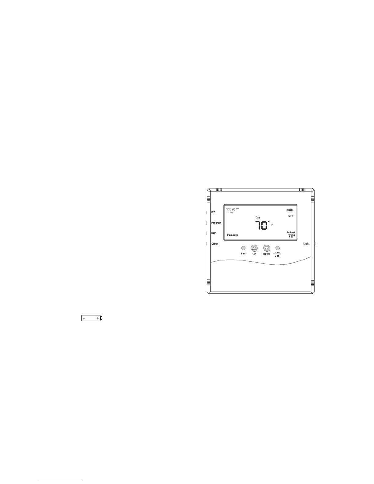
Figure 1. T9000 Front View
Replacing Batteries
To open the thermostat, use both hands and press the two
push-tabs on the bottom of the thermostat housing with your
thumbs while pulling the front of the thermostat away from
the base (Figure 2)
Introduction
The T9000 Wireless Temperature Control is a two-part
wireless thermostat system designed to provide precision
temperature control without the installation labor and expense
of wiring. Powered by AA batteries, the thermostat can operate
continuously for approximately 18 months, and can be mounted
in any suitable location that will provide good temperature
control. A large LCD display (Figure 1) provides the user
with current room temperature, set point temperature, time,
program interval, and other system status information. In hotel
applications, programming, clock set up buttons and associated
display information are typically not displayed. The second part
of the T9000 system is called a Remote Control Node or “RCN”.
An RCN interfaces with specic desired HVAC equipment,
and communicates with its thermostat using unlicensed 900
MHz, radio frequency energy. At the time of installation, the
T9000 thermostat is linked to one or more RCN controls. The
thermostat and RCN that have been linked will not interfere
with, or be affected by, any other thermostat or RCN in adjacent
rooms, apartments, or neighboring homes.
Batteries
Installing/Changing
A low battery icon will light on the thermostat
display when the batteries are within approximately one week
of being exhausted. The T9000 is designed to use standard
Page 5

OM 897 / Page 5 of 20
Figure 2. Opening Thermostat
The T9000 operates with either two or four AA batteries. Four
(4) batteries double the time between battery changes (the
average user can expect 1 to 1.5 years of battery life). Batteries
are paired, one set on top of the other (see Figure 3).
Figure 3. Battery Location
Note: Do not mix old and new batteries. When batteries are
changed, replace them all at the same time
Programmed data for heating, cooling and time of day will be
lost when batteries are completely removed or depleted and will
have to be re-enterend along with resetting the clock. To avoid
this, batteries can be replaced one set at a time before they are
depleted. However, after the rst set is replaced, immediately
replace the second set with new batteries.
Mounting
Find a suitable location for mounting your thermostat, preferably
an interior wall centrally located within the conditioned space
at about 5 feet above the oor. Try not to locate the thermostat
in a place where it could be exposed to heat such as a warm air
vent, or where it could be exposed to direct sunlight.
Wall-Mount
The T9000 back mounting plate provides six (6) mounting
holes. The upper and lower holes on the vertical centerline
will match up with screw positions of a standard electrical
switchbox or dry-wall mounting ring.
Step One
Remove the back plate from the thermostat housing (Figure 2)
and use it to mark locations for mounting holes. While operation
of the thermostat is not affected by orientation, we recommend
Base Plate
Front Cover
Latches
Circuit Board
Set A
Set A
Set B
Set B
Thermostat opened back
Thermostat will operate on
either Set A, Set B or both.
When changing, replace with
all new batteries. Never use a
mix of old and new.
Battery orientation is crtitical.
Thermostat open back
Page 6
Page 6 of 20 / OM 897
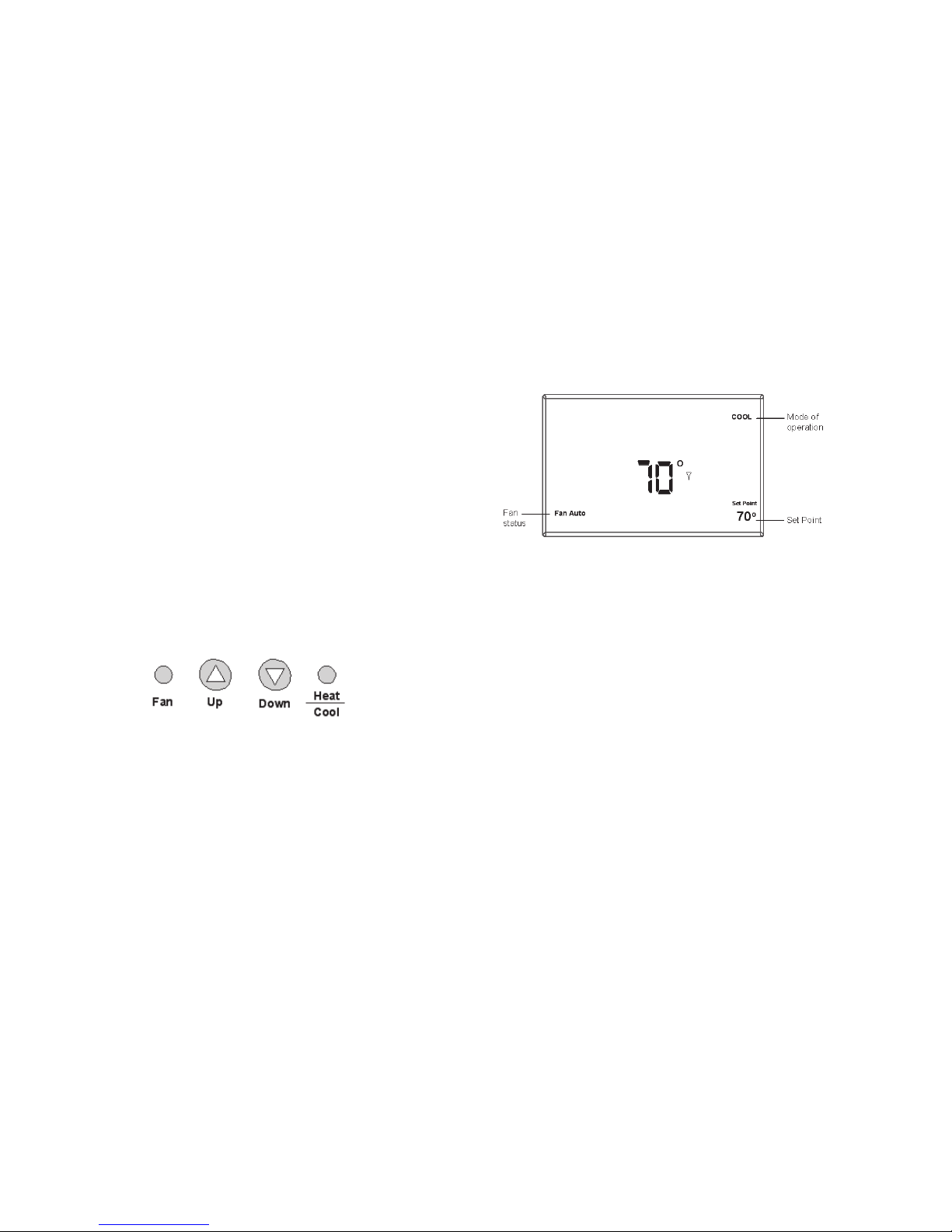
Figure 5. General Operation Display
Note that the UP, DOWN and HEAT/COOL buttons are also
used in setting the clock and programming the thermostat,
and linking to nodes. This will be covered in the following
sections of the manual.
Four buttons located on the left side of the thermostat (refer
to Figure 1 & 12) control display of temperature in either
Fahrenheit or Celsius, programming, clock setup and control of
whether the thermostat is under manual or program control.
• F / C – Toggles Fahrenheit Celsius display
• Program set up button
• Run – Sets program or manual mode of operation
• Clock set up button
using a level across the top or side of the base plate to provide
a professionally installed appearance.
Step Two
Drill 3/8" holes and insert drywall fasteners (#6 screws
recommended) and fasten the back plate to the wall.
Back Stand
Located on the back of the housing is a built-in, hinged stand
support. This feature permits the thermostat to stand on a at
surface, such as a table or shelf, in the event that a permanent
mounting to the wall is not desired.
Buttons
Four buttons are located on the front of the T9000.
Figure 4.
These buttons are used in adjusting fan operation, changing the
set point temperature up or down, and changing the operating
mode of the thermostat. See Figure 1 & 12 for front view
of the thermostat and button locations. Figure 4 shows the
display items that are changed by these four buttons in normal
operation.
Page 7

OM 897 / Page 7 of 20
Backlight
A single button on the right hand side of the thermostat
activates the display backlight. When pressed, the backlight will
illuminate the display briey and turn off. If other buttons are
pressed immediately after the backlight button, the display will
stay illuminated until a few seconds after all button activity has
ended. Backlighting takes signicant energy from the batteries
and should be used sparingly. Frequent use of the backlight
function will noticeably reduce battery life.
Setting The Clock
In all setup modes, the T9000 will ash the display item you are
about to change. The UP and DOWN buttons change settings,
the HEAT/COOL button is used to move to the next item.
To set the clock, you will use the buttons marked CLOCK,
UP, DOWN, and HEAT/COOL.
Step 1
Press the CLOCK button. The hour digits will ash. Press the
UP or DOWN button to change the hour. Note that AM/PM
will change as you roll the hour past twelve. Be sure to set the
hour properly for AM or PM. Press the HEAT/COOL button
to keep the hour you’ve just set and move to minutes.
Step 2
The minute digits will now be blinking. Press the UP or DOWN
button to change to the desired minute. When the correct minute
is ashing press HEAT/COOL.
Step 3
One of the seven day icons (Mo, Tu, We, Th, Fr, Sa, Su) will now
ash. Press UP or DOWN until the correct day icon is ashing.
When the correct day is ashing, press HEAT/COOL.
Step 4
Press the clock button to keep all clock changes you’ve made
and resume normal operation.
Thermostat
Programming
The T9000 provides for program periods: Morning, Day,
Evening, and Night. The time and temperature can be set for
each period. Upon initial power-up the T9000 loads time and
temperature program default parameters for weekday and
weekend days. The default program perimeters conform to
Energy Star guidelines, and are a good point from which to
start.
Page 8

Page 8 of 20 / OM 897
The default program parameters conform to Energy Star
guidelines and are a good point from which to start. Default
settings are:
Weekday Default Program Times
and Temperatures
Period Time Heat Cool
Morning 6:00 AM 70° 75°
Day 8:00 AM 62° 83°
Evening 6:00 PM 70° 75°
Night 11:00 PM 62° 78°
Weekday Default Program Times
and Temperatures
Period Time Heat Cool
Morning 8:00 AM 70° 75°
Day 10:00 AM 62° 83°
Evening 6:00 PM 70° 75°
Night 11:00 PM 62° 78°
Separate heating and cooling programs can be entered. The
mode of the thermostat is displayed in the upper right side
of the LCD screen. Figure 1 on page 4 for instance, shows
a thermostat in COOL mode. The mode the thermostat is in
when the PROGRAM button is pressed is the mode that will
be controlled by the program. If it is in the cool mode, as
shown in Figure 1, the program entered will be stored as the
program for cooling.
To program the thermostat, you will use the PROGRAM,
HEAT/COOL, UP, and DOWN buttons.
Step 1
The press the PROGRAM button to put the thermostat into
the programming mode. The display will blink all of the day
of the week icons. Pressing the UP or DOWN button will
toggle between (weekday) icons and the (weekend) icons.
Ensure the display is blinking the day you want to program.
Press HEAT/COOL.
Step 2
Next the morning period will blink. Use the UP or DOWN button
to toggle through Morning, Day, Evening, or Night, stopping
at the period you want to program. Press HEAT/COOL.
Step 3
Next, the hour of the day will blink. This is the starting hour of
the period you have selected. Use the UP or DOWN button to
change the selected hour start time. Press HEAT/COOL.
Page 9

OM 897 / Page 9 of 20
Step 4
The minute of the day will blink next. This is the starting minute
in the hour. Use the UP or DOWN button to change the minute
digits to the desired setting. (Note that the minutes change in
ve-minute increments.) Press HEAT/COOL.
Step 5
The desired set point will now be blinking. This is the
temperature set point for the time of day you have selected. Press
the UP or DOWN button to change the set point temperature
to what you want. Press HEAT/COOL.
This completes the programming of the rst period of the
day.
Step 6
If you started with the morning time period, the next period,
day, will now be blinking. Follow steps two, three, four, and
ve for each period you wish to program.
Navigating
You can quickly step through to a specic item you want to
change by pressing the HEAT/COOL button until the item you
want to change is ashing. When that item is ashing, use the
UP or DOWN button to adjust.
Exiting Program Mode
Pressing the program button at any time will exit out of the
programming mode, save your changes to memory and return
to normal thermostat operation.
Run Button
Program / Manual Operation
The RUN button toggles the thermostat between manual
operating mode and program operating mode. When in the
program mode your thermostat responds to the times and
temperatures programmed.
Figure 6. Program Mode Display
Figure 6 shows the thermostat running in the program mode.
One of the four periods, in this case “Day”, is displayed,
letting you know which period of the day it is in. When in
the manual mode as shown in Figure 7, the period of the day
is not displayed. Instead the word “Hold” will be displayed
Page 10

Page 10 of 20 / OM 897
above the Set point temperature, indicating the thermostat is
holding that temperature.
In manual mode, you can adjust the desired temperature using
the UP and DOWN buttons, and the thermostat will maintain
the temperature until you change it again.
Figure 7. Manual Mode Display
Changing Temperature While Running A
Program
You can always change the temperature up or down while a
program is running. However, when the program moves to the
next period, the program set point temperature for that period
will take effect. For instance, assume the current program
period is Evening, with a programmed temperature of 70°,
and the next period, Night, is programmed for 65°, scheduled
to start at 11:00 PM. If during the Evening time period you
desired the space to be warmer, you could press the UP button
to raise the temperature set point. The thermostat will hold that
temperature until the next program period, at which point the
temperature will adjust to the programmed temperature set
point for that period. In this case the Night period is set for
11:00 PM and 65°.
Installing and Removing Nodes
A T9000 thermostat and remote control node will not operate as
a system until they are linked together through the installation
process. The linking process binds one or more control nodes
to a thermostat so that they will communicate with each other
as a control system. Up to eight nodes can be linked to a single
thermostat. Until linked, the control node will not operate.
Once linked, a control mode will only respond to its specic
thermostat. The thermostat and RCN that have been linked will
not interfere with, or be affected by, any other thermostat or
RCN in the adjacent rooms, apartments, or neighboring homes.
Linking information is stored in non-volatile memory – it is not
necessary to Re-link the thermostat and RCN if the thermostat
batteries are removed, or after a power outage.
Installing Nodes
If multiple installation teams are installing and linking
thermostats at the same time, coordinate the activity to avoid
the possibility of installers simultaneously attempting to perform
the linking process. Because this is an RF system, installers
in nearby rooms/areas where it is possible RF overlap could
exist, run the risk of interfering with each other.
Page 11

OM 897 / Page 11 of 20
Installation and linking activity going on around a system
already installed will not interfere with it.
Refer to Figure 8 for inside thermostat buttons and jumper
locations and functions.
Step 1
Press the SW4-INSTALL. button inside the thermostat. The
display will change to the Install Session screen shown in
Figure 8, with the “install” icon blanking.
The display always blinks the item that is active and can be
changed.
Figure 8. Internal Buttons
Step 2
The UP button on the front of the thermostat is used to toggle
between the following two choices:
Install - Install a Node
Remove - Uninstall ALL Nodes
(The Remove option will be discussed later.)
SW12-RESET SW4-INSTALL SW9-LINK
PB1-NETWORK
Set A Set A
Set B Set B
SW12-RESET
SW4-INSTALL
SW9-LINK
Internal T9000 buttons
PB1-NETWORK
Used to uninstall the thermostat
from node(s) it has been linked to.
SW12-RESET
Master Reset – Returns
thermostat to all factory defaults.
SW4-INSTALL
Starts an installation session.
SW9-LINK
Used to Link the thermostat to
control nodes.
PB1-NETWORK
JP3 - Program
JP4 – Non Program
Program Jumper
JP3 = Programmable
JP4 = Non-Programmable
Page 12

Page 12 of 20 / OM 897
Figure 9. Install Setup Display
Press the HEAT/COOL to select install.
Step 3
The node number digits will now ash. Use the UP button to
set the node number you wish to install 0-7. If this is the rst
node or only node to be installed to this thermostat, leave the
node number at zero.
Press the HEAT/COOL button to select the node number.
Step 4
The control node can be installed to a thermostat as a HEAT
only, COOL only or HEAT & COOL node. After selecting
the node number, the HEAT and/or COOL icon will ash in
the upper right hand quarter of the display is shown in Figure
9. Press the UP button to scroll through the following three
choices:
Heat - Install node as a heating only control
Cool - Install node as a cooling only control
Heat/Cool - Install node as a heating and cooling control
Press the HEAT/COOL button when the appropriate icon is
displayed.
At this point all selections have been made and nothing on
the display should be blinking. You are now ready to install
a node.
Note: There are several types of remote control nodes that can
be linked to the T9000 thermostat. Refer to a specic node
documentation for details about the nodes you are using. In
every case, a node is linked to a thermostat using the same
procedure as described, and involves either pressing the Link
Service Request button on the node, or powering the node up
from the “Off” state.
Step 5
Press the SW9-LINK button on the back of the thermostat
printed circuit board. Within 5-seconds, activate the link
service request on the control node you are installing by the
following method:
Model 122 - 24VAC Node – Apply power or press PB3, see
Figure 10.
Page 13

OM 897 / Page 13 of 20
When the SW9-LINK button is pressed, the thermostat will
display a “Please Wait” message (see Figure 11) in the bottom
right corner of the LCD while it searches for a node. You have
several seconds to initiate a Link Service Request at the control
node. Often it is easiest to have the thermostat in your hand
while you are near the node. The thermostat will link with the
rst node it hears that indicates a Link Service Request. It is
for this reason that multiple installations must be coordinated.
(see note in Installing Nodes section.) Once the thermostat nds
a node, linking information is exchanged, the “Please Wait”
message is extinguished, and a “Good” message will appear
as shown in Figure 11.
Figure 11. Install – Link Display
If another node is to be installed to this thermostat, press the
HEAT/COOL button again. The “Install” icon will ash. As
was done previously, press the HEAT/COOL button (Step Two).
The node number will begin blinking, select the node number
by one using the UP button and continue with the remaining
steps. When all nodes are installed, press the SW4-INSTALL
button to close the installation session and return to normal
thermostat operation.
If for any reason there was a problem encountered during
the nal installation and linking step, a “Bad” message will
be displayed. If this happens, repeat the “Installing Nodes”
process from the beginning. If the problem persists, perform
a “Thermostat Installation Reset” on page 14 and repeat the
“Installing Nodes” process.
Figure 10. PTAC Wireless Control Node
Page 14

Page 14 of 20 / OM 897
Installing Multiple Nodes to a Thermostat
Multiple nodes are typically installed to a thermostat by
linking each as a different number (0-7). If a node is not
sending a signal to the thermostat for any reason, such as
loss of power, it will turn off the antenna symbol indicating a
break in communication and attempt to nd the missing node,
increasing battery power drain. If, in your application, a node
may be removed or powered down at times, consider linking
all nodes as the same node number, node 00 for instance. As
long as the thermostat hears back from at least one node, it
will consider the communication to be good. (See Frequently
Asked Questions, page 15)
Un-Installing Nodes
Un-installing nodes, the procedure to remove will un-install
all nodes at once.
Step 1
Press the SW4-INSTALL button inside the thermostat. The
Install icon will ash. Press the UP button to select “Remove”
and press HEAT/COOL to select. The HEAT and/or COOL
icons will be displayed and all display items will be on steady;
nothing will be ashing.
Step 2
Press the SW9-LINK button on the back of the thermostat
printed circuit board. Within 5-seconds, activate a Link
Service Request on the control node. When the SW9-LINK
button is pressed, the thermostat will display the “Please
Wait” message (see gure 11) in the bottom right corner of
the LCD while it searches for nodes. Once the thermostat nds
its installed node(s), linking information is removed from
the nodes and the thermostat, “please wait” message will be
extinguished, and a “Good” message will appear as shown in
Figure 11.
Thermostat Installation Reset
In the event there is difculty installing a node, perform the
following:
Step 1
Press the SW4-INSTALL button inside the thermostat. The
install icon will ash. You only need to begin the installation
session to perform this reset.
Step 2
Press and hold the PB1-NETWORK button (see Figure 8, page
11) on the inside of the thermostat board for approximately
two seconds.
No response is displayed. All previous installation records will
be wiped from the thermostat memory. You can continue from
this point with the installation procedure. PB1-NETWORK will
only reset the thermostat installation database if the thermostat
Page 15

OM 897 / Page 15 of 20
is already in an Installation Session (SW4-INSTALL button
has been pressed). Otherwise, the PB1-NETWORK button
will have no affect.
Frequently Asked Questions
“Where should I locate my thermostat?”
For best results, the thermostat should be located approximately
5 feet above the oor on an inside wall in an area with good
air circulation. Avoid drafts from your air ducts and windows,
and heat from the sunlight, lighting xtures, appliances,
replaces, etc.
“What does the antenna symbol on the display mean?”
The T9000 thermostat displays the antenna symbol as indication
that it is communicating with its remote control node(s) (RCN).
If communication is not established, the antenna symbol will
go out.
“What do I do if the antenna symbol is no longer
displayed?”
Ensure the RCN has power. Make sure the thermostat and RCN
are in fact linked. Force the thermostat to talk to its RCN by
pushing the FAN button. If communication is successful, the
antenna icon will turn back on. Coincidental RF interference
could cause a temporary loss of communication. In virtually
all such cases, the interference is temporary.
“Can I run multiple heating or cooling loads such as electric
baseboard heating and a window air conditioner with one
T9000 thermostat?”
Yes. In fact one T9000 thermostat can control up to eight
different RCNs.
“Why would I install multiple nodes as the same
number?”
A residential example might be several space heaters being
controlled by one thermostat. Space heaters are portable and
may be moved. A wall plug control node could on occasion
be unplugged. If it is installed to its thermostat as a different
node number, the thermostat will always look for that node,
increasing the number of times it attempts communication. If
all nodes are installed as the same number and the thermostat
hears from at least one, it will consider the communication
good. In a hotel meeting room with multiple packaged terminal
air conditioner units, seating may be arranged such that one
unit blows air directly on some people. The thermostat in this
case will not continuously look for a missing node if that one
unit is powered off.
Page 16

Page 16 of 20 / OM 897
“When my a/c. turns off, I can’t immediately make it run
again?”
This is normal. What you are experiencing is called in anti shortcycle delay. Because of high pressure in the air conditioning
compressor system, it’s not a good idea to start your air
conditioner immediately after it has just shut down. The T9000
prevents this from happening by imposing a 3-minute delay.
“I just installed the thermostat and the antenna symbol
comes and goes. What should I do?”
A poor RF signal between the thermostat and one or more RCNs
is the cause. The further away the thermostat and RCN are from
each other, the weaker the signal becomes. Distance and also
building materials, particulary metals, will block the RF signal
energy. Sheet metal is very often the problem. Changing the
position of the RCN or thermostat or both may be required. In
rare cases, where the RCN is heavily shielded, a small section of
sheet metal may need to be removed and if necessary replaced
with plastic or other nonmetallic material.
Note: Always seek competent professional electrical and HVAC
contractors when working with your heating and cooling system
and the electrical wiring in your home or other property. For
safety and warranty reasons, always consult with a HVAC
contractor and/or the original equipment manufacturer before
making changes.
“The display on my thermostat is blank. What
happened?”
A blank display indicates your batteries are depleted. When the
low battery icon comes on there is approximately one week of
battery life remaining (see the Batteries - Installing/Changing
section of this manual for information on changing the batteries).
We recommend that when you change batteries, always use
batteries that you know are fresh. Use four (4) new high quality
AA batteries. If you’re using the T9000 to control a heating
system, we recommend as a general practice, putting fresh
batteries in at the start of the heating season.
“If I am away for an extended time such as vacation,
how do I set the thermostat so my system does not run
excessively ?”
You have a couple of choices. The rst is to press the HEAT/
COOL button on the thermostat until the display reads “OFF”
(Particularly during the heating season, we do not recommend
going to the “off” mode.) The second option is to put your
thermostat in manual mode by pressing the RUN button. You
know that you’re in the manual mode because none of the period
icons, Morning, Day, Evening, or Night will be displayed.
The “Hold” icon located above the set point temperature will
be displayed (Refer to Figure 7). Next, adjust the set point
temperature to minimize system operation. For example, you
could adjust to a set point of 85°F in cooling, or 65°F in heating,
Page 17

OM 897 / Page 17 of 20
staying mindful of what your temperature selection could affect
such as plants and animals that stay in your home while you
are away. During the cooling season, consider humidity as well
as room temperature. When your air conditioner runs, it not
only cools the air, it also removes moisture, lowering humidity.
High humidity can encourage mold growth.
“Can I use another T9000 thermostat without
interference?”
Yes. A T9000 thermostat and its RCN will talk between
themselves, but will never respond to or control another
thermostat in adjacent rooms, apartments, or neighboring
homes.
Page 18

Page 18 of 20 / OM 897
Figure 12. T9000 Overview
Page 19

OM 897 / Page 19 of 20
Page 20

McQuay Training and Development
Now that you have made an investment in modern, efcient McQuay equipment, its care should be a high priority.
For training information on all McQuay HVAC products, please visit us at www.mcquay.com and click on training,
or call 540-248-9646 and ask for the Training Department.
Warranty
All McQuay equipment is sold pursuant to its standard terms and conditions of sale, including Limited
Product Warranty. Consult your local McQuay Representative for warranty details. Refer to Form
933-43285Y. To nd your local McQuay Representative, go to www.mcquay.com.
This document contains the most current product information as of this printing. For the most up-to-date
product information, please go to
www.mcquay.com.
© 2009 McQuay International ● www.mcquay.com ● (800) 432-1342 OM 897-1 / 8-09 Page 20 of 20
 Loading...