

Page 1
Operation & Maintenance Data
Digital Control
For Incremental® Top-mounted Hydronic Heat Comfort Conditioners
OM 813
Group: PTAC
Part No: 106878501
Date: August 2005
Page 2
Contents
Product Nomenclature ................................................ 2
Introduction ................................................................. 3
Application.................................................................. 3
Inputs and Outputs ..................................................... 3
User Interface ............................................................. 4
T ouch Pad................................................................... 4
Unit Operation ....................................................... 5-8
Last setting memory back up ............................... 5
On/Off triggering ................................................... 5
Off Mode............................................................... 5
T emperature Range .............................................. 5
Indoor and Outdoor Fan Operation........................ 5
Damper Control .................................................... 5
Wireless Remote (Optional .................................... .5
Mode Buttons ............................................................. 5
Modes of Operation................................................. .6
Cool Mode .................................................................. 6
Cold Start.................................................................... 6
Sleep Function............................................................ 6
Cool/Dry Mode............................................................ 6
Product Nomenclature
Heat Mode .................................................................. 7
1) Hot St art........................................................... 7
2) Hydronic Heat .................................................. 7
3) Sleep Function ................................................. 7
4) Fan Mode ......................................................... 7
Set Up Mode .......................................................... 7-8
Control Selection ........................................................ 7
T emperature Limit Settings......................................... 7
Hydronic V alve Operation ............................................ 7
Indoor Air Sensor Reading .......................................... 7
Indoor Coil Sensor Reading......................................... 7
Outdoor Air Sensor Reading ....................................... 8
Thermistor failure Code/Condition ............................... 8
Compressor random restart ........................................ 8
Unit Protective Logic................................................ 8
Compressor minimum run time ................................... 8
Compressor minimum off time .................................... 8
Antifreeze protection ................................................... 8
Room freeze protection ............................................... 8
T emperature limiting.................................................... 8
Outdoor air low ambient lockout.................................. 8
PDNS1009 E Z 62 Z 12AR14 C I C 1
Product Category
P = PTAC
Product Identifier
DNS = A/C w/Top-Mnt Hyd Heat
(Flat Top)
DNC = A/C w/Top-Mnt Hyd Heat &
Corrosion Protection (Flat Top)
Design Series
1 = A Design 4 = D Design
2 = B Design 5 = E Design
3 = C Design
Nominal Capacity
007 = 7,000 015 = 15,000
009 = 9,000 016 = 16,000
012 = 12,000
Voltage
A = 115-60-1
C = 206-60-1
J = 265-60-1
S = 208-115-60-1
Coil Options
Heating Options
62 = Hydronic, normally open
63 = Hydronic, normally closed
Product Style
1 = 1st Style Change
SKU Type
A = Stock
B = Quick Ship
C = Tailored
Color
I = Antique Ivory
Power Connection
C = Cord
Return Air
14 = Bottom w/Motorized Damper
34 = Bottom w/Manual Damper
Discharge
AR = Flat Top
Electromechanical Controls Solid State Control
12 = Unit Mount MCO 55 = Unit Mount MCO
13 = Wall T stat 56 = Hand Held Remote Wireless
21 = Unit Mtd. MCO w/Heat 57 = Wall Mounted Remote T'stat
Fan Lockout
26 = Unit Mtd. MCO w/ GRC & NSB
24 = Unit Mtd. MCO w/NSB
Hand Orientation
Z = Not Applicable
C
“McQuay” is a registered trademark of McQuay International.
©McQuay International 2005. All rights reserved throughout the
world.
Page 2 of 8 PTAC Digital Controls OM 813
The information in this manual supersedes and replaces previous
catalogues with regards to McQuay Packaged Terminal Air Conditioning products. Illustrations cover the general appearance of McQuay
International products at the time of publication and McQuay International reserves the right to make changes in design and construction
at anytime without notice.
Page 3
Introduction
Certified Drawing
This Operation and Maintenance Manual includes information
on the controller set up and operation and operating parameters.
It also explains the operation of the built-in equipment
protective logic of the controller.
Application
The PDNS Digital Control is used to control units that include
both an integral air conditioner and a source of heat. The
Digital Control is operated with a T ouch Pad.
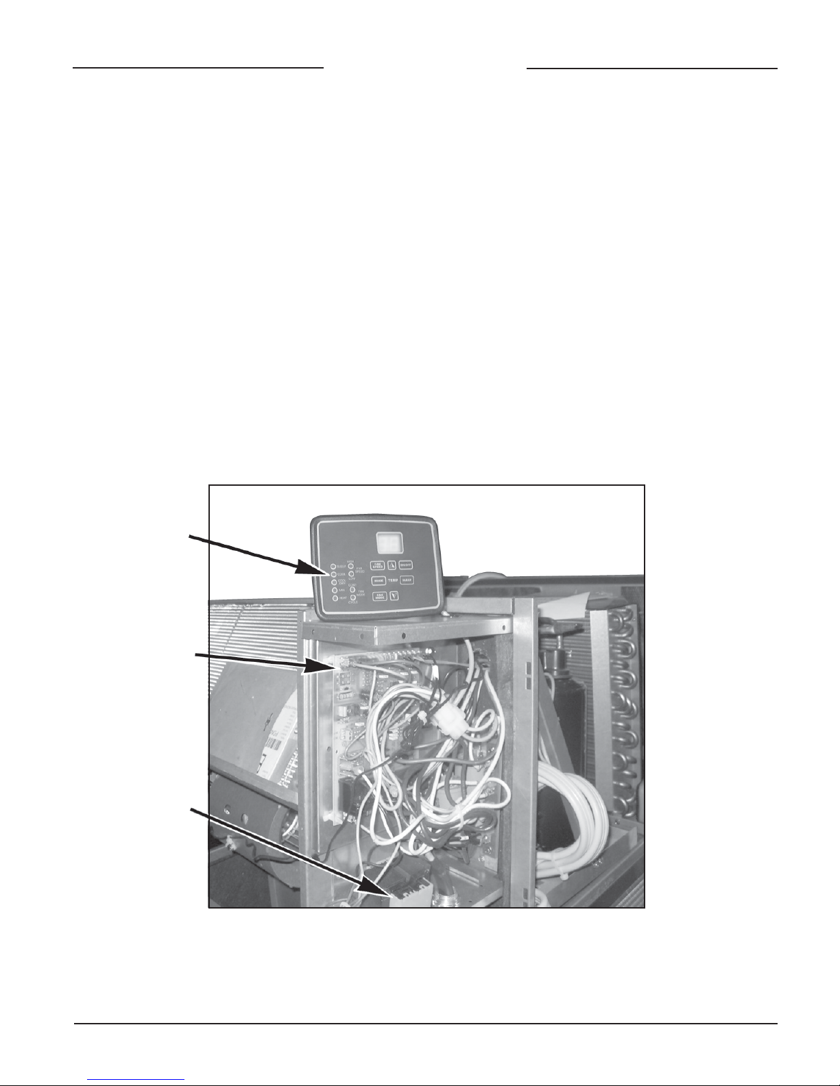
Figure 1. Digital Control Components
Inputs and Outputs
The Digital Control offers the following inputs:
• Indoor Coil Sensor (ICS)
• Indoor Air Sensor (IAS)
• Outdoor Air Sensor (OAS)
• Inputs from Remote Thermostat, RBGYW
• Heat Fan Lock Out Sensor (HFLO)
• Power Supply, 24VAC
The Digital Control offers the following outputs:
• Compressor output (COM)
• Outdoor Fan (FAN)
• Indoor Fan (BLOWER HI, BLOWER LO)
• Damper Control (DAMPER)
• Hydronic V alve (HYV)
Touchpad and Display
(Low Voltage)
Main Control Board
Transformer (24 VAC)
OM 813 PTAC Digital Controls Page 3 of 8
Page 4

Figure 2. Digital Controls on PDNS Unit
Touchpad and Display
(Low Voltage)
Communication
User Interface
Table 1. Touch Pad Descriptions
Keys and Indicators Labels
7 Push Buttons
9 LED Indicators
LED 2 Digit Displays
Figure 3. Digital Control Touch Pad Display
9-LED Indicators
ON/OFF, FAN SPEED, F AN MODE, SLEEP, MODE
T emp buttons: Arrow Labels for Temp UP and DOWN
SLEEP , COOL, COOL/DR Y, FAN, HEA T, HIGH, LOW, CYCLE,
CONT .
LED 2-Digit Display
7- Push Buttons
Display Function Legend
Tr = Room T emperature Ts = Temperature Setpoint t = T i m e
tP = Touch Pad Control rT = Remote Thermostat Control rF = Room Freeze Condition
Page 4 of 8 PTAC Digital Controls OM 813
Page 5

Unit Operation
Last Setting Memory Backup
The digital control will start with the last settings used prior to
power down. These settings are saved in a not-volatile memory
and the default mode is OFF.
On/Off T riggering
The Control can be turned On or Off via the touch pad. The
Control will show the temperature set point when turned on.
In the Fan Mode, the display is blank.
Certified Drawing
Damper Control
Damper control is user selectable via a jumper on the board for
one of two modes:
1) Automatic when the jumper is present. The control is
shipped with the jumper on.
In the Automatic Mode, the damper will open when the indoor
fan is operating and close when it is not.
1. On/Off triggering with the touch pad:
Control will turn ON or OFF when the On/Off button is
pressed on the touch pad control. Once turned on, the
control will start on the last mode used before it was turned
OFF .
2. On/Off triggering with the SLEEP Feature:
The SLEEP Feature works in combination with the Timer
Setting. Sleep Timer setting is adjustable from 1 to 15
hours via the touch pad. The Timer counts down to “0”
and turns the Control OFF if it was previously ON or vice
versa.
NOTE: Sleep Operation is overridden by the room freeze
protection.
OFF Mode
When the control is in the OFF MODE, relay outputs will be
disabled with the exception of the indoor fan (blower). It will
stay on to meet the Hot Keep specification. Indicator LED’s
are all off. The normally open hydronic valve will be powered
closed in the OFF MODE.
Temperature Range
The maximum operating temperature range is selectable via
the T ouch Pad and is 60°F to 85°F.
Indoor and Outdoor Fan Operation
The indoor fan can be set to operate on High or Low speed
with the Fan Speed Button on the touch pad. It can also be set
for Continuous or Cycled operation on the touch pad. When
set for Continuous, the “CONT” LED will be on and the fan
will run continuously. When set for Cycle, the “CYCLE” LED
will be on and the fan will turn on at a call for heat or cooling.
• Fan Cycle Operation:
On a call for Heating or Cooling, the indoor fan and the
heating source or the compressor will be activated. When
the call is satisfied and the heating source or the
compressor is deactivated, the indoor fan will repeatedly
run for 2 minutes on and 30 minutes off, until the next cutin cycle.
• With a single (1) motor PT AC:
The outdoor motor speed is determined by the indoor fan
speed.
• With a (2) two motor PT AC:
The compressor and the outdoor fan are controlled
simultaneously.
2) In the Manual Mode the damper is opened and closed
manually.
Wireless Remote Control (Optional)
T o add to existing Digital Control unit s, codes 55, 56
or 57, Front Panel Part No. 668104501 and Infrared
Control Kit Part No. 107029001 must be ordered.
The Remote Consists of 10 Push-buttons
• Power:
Functions same as ON/OFF button on the touch pad.
• Sleep:
Functions same as SLEEP button on the touch pad.
Mode Buttons
• Heat, Cool, Cool/Dry, Fan:
Performs same function as the MODE button on the touch
pad, and allows user to select specific mode of operation
using only one button.
• T emp Buttons +, – :
Functions same as buttons on touch pad, allowing user
to change the setpoint.
• Fan Speed Buttons (High & Low):
Performs same function as the F AN SPEED button on the
touch pad, allows user to select specific speed using only
one button.
Remote must be aimed in a line of sight of the window in upper
right corner on the front panel, at less than a 45o angle from
center of the window.
The control board will beep when any button is pressed on
the remote control to confirm signal.
OM 813 PTAC Digital Controls Page 5 of 8
Page 6

Modes of Operation
Cool Mode
In Cool Mode, the compressor will start if the temperature at
the space temperature sensor is 1°F or higher than the set
point. It will stop if the space temperature sensor is 2°F or
lower than the set point, subject to timing requirements.
In the Cool Mode, the indoor fan will operate according to the
user settings for Fan Mode – Continuous or Cycle and Speed.
Figure 4. if Tr - T s > 4°F, operation will be in Zone A
Figure 5. if 2°F < T r - T s < 4°F , operation will be in Zone B
Figure 6. if 0°F < T s - Ts < 2°F, operation will be in Zone C
Figure 7. if T s - Tr > 5°F , operation will be in Zone D
The other temperature ranges are dead bands for zone stability .
Figure 4. Zone A
On
Off
Compressor
t
Cold Start
Cold start is initiated when the control hasn’t called for cooling
for more than two (2) hours, or during a power-on-reset.
During cold start, the set point is lowered by 4°F (T set-4°F) if
the differential calls for cooling. The unit will operate in cold
start until the new set point is satisfied (+ or – 1°F), or until the
unit has run in cold start for at least 20 minutes. After one or
both conditions are met, the set point will be reset to the user
setting and the unit will run in the regular cool mode.
The indoor fan will operate according to the user settings for
mode – Continuous or Cycle and Speed.
Cold start is not available with the Sleep feature.
Sleep Function
Sleep time is adjustable by the user from 1 to 15 hours in one
(1) hour increments in a closed loop. The sleep time is adjusted
and set via the touch pad and by pressing the Sleep Button
repeatedly. On the touch pad, the display will show the set
time in numbers for five (5) seconds. Before the sleep time
expires, the setting can be adjusted above the number of hours
passed by pressing the Sleep Button. Pressing the On/Off
Button can terminate the Sleep Mode.
A changeover from Heat to Cool or another Mode will reset
the Sleep Timer .
On
Off
Figure 5. Zone B
On
Compressor
Off
On
Low Fan
Off
Figure 6. Zone C
On
Com pressor
Off
Low Fan
*
12 mins.
= Zone Determination Time
*
8 mins .
30 secs.
6 mins.
4 mins.
30 secs.
6 mins.
t
t
t
t
The Sleep Function will be deactivated by pressing the power-
Off
On
30 secs.
30 secs.
= Zone Determination Time
*
t
*
on-reset or any button (except sleep) on the touch pad or the
Remote Control.
Cool Dry Mode
Select the Cool Dry Mode when the standard Cool Mode does
not provide sufficient dehumidification. In Cool Dry Mode,
the unit must run in Cool Mode for 12 minutes or until the
Low Fan
temperature differential between the room temperature and
the set point is less than 2°F . This will also occur after a Cold
Start or a Mode change from Cool to Cool Dry. During this
time the fan will operate in the Mode and Speed selected.
Until one or both of the above conditions are met, the control
Figure 7. Zone D
On
Off
Fan
t
will determine which Dry Mode (Zone) is initiated based on
the temperature differential between the room temperature (Tr)
and the temperature set point (Ts):
On
Off
Page 6 of 8 PTAC Digital Controls OM 813
Compressor
*
12 mins.
= Zone Determination Time
*
t
Page 7

Heat Mode
The unit will call for heat when Tr - T s < 0°F becomes true.
1) Hot Start:
Hot Start is possible when the control hasn’t called for
heat in more than (2) hours or during power-on-reset.
During Hot Start, the user’s set point is raised 4°F (Ts +
4°F). The unit will only call for heat if room temperature
differential calls for heat. The unit will continue in Hot
Start Mode until the new set point is satisfied (with a 1°F
differential) or unit has run for at least 20 minutes. After
one or both conditions are met, the set point will be reset
to the user's setting and the unit will run in regular heat
mode. Hot start is not available with the Sleep feature.
The fan will operate per the Fan Mode and Speed setting.
Settings within the Set Up Mode are as follows:
Certified Drawing
Control Selection:
To view the Control Selection Screen, press and hold the Up
and Down buttons for 5 seconds. The setting may be changed
by pressing either the Up or Down button. The “tP” setting is
the default setting and indicates the touch pad control.
Temperature Limit Settings
To advance from Control Selection to Temperature Limit
Settings, press the Mode button once. To set the Cool
Minimum set point, press and hold Fan Cycle button and adjust
the setting with the Up or Down buttons. The minimum
setting is 60°F.
2) Hydronic Heat:
Hydronic Heat control is configurable in the Set up Mode
for Normally Open or Normally Closed valve control. The
heat valve opens when the room temperature is 0°F below
set point. The heat valve closes when the room temperature
is 3°F greater than the thermostat setting.
a) Hot Keep:
When the water valve closes, the indoor fan will
operate per the user mode (Constant or Cycle) and
speed setting.
b) Heat Fan Lockout (HFLO):
Heat Fan Lockout will turn off the indoor fan if the
HFLO sensor is open (does not sense hot water or
steam) for two (2) seconds. The fan will restart when
the sensor closes.
3) Sleep Function:
Sleep time is user adjustable from 1 to 15 hours in one
hour increments, in a closed loop via the touch pad, by
pressing the Sleep button repeatedly. The Sleep Mode
can be terminated by pressing the On/Off button.
The Sleep Function will lower the temperature setting with
time. Changing the Mode or a changeover from Heat to
Cool will reset the Sleep Timer .
To set the Heat Maximum set point, press and hold Fan Speed
button and adjust the setting with the Up or Down buttons.
Maximum setting is 85°F .
The Display will show the upper operating limits first. The
default settings are Cool min. = 60°F and Heat max. = 85°F .
Hydronic Valve Operation
To advance from T emperature Limit Settings to Hydronic Valve
operation, press the Mode button once. To toggle the setting,
press either the Up or Down button. Settings are “no” (normally
open) and “nc” (normally closed). Default setting is “no”.
Figure 8. Indoor Air and Indoor Coil Sensor Locations
Indoor
Coil Sensor
(ICS)
Indoor
Air Sensor
(IAS)
The Sleep function will be deactivated by Power-on-reset,
or by pressing any button on the T ouch Pad except Sleep.
4) Fan Mode
In the Fan Mode, the fan will operate continuously at the
user’s speed setting. The compressor and outdoor fan
will not operate. In single motor units, the outdoor fan
will run along with the indoor fan.
Set Up Mode
T o enter the Set Up Mode, simultaneously press the Mode Up
and Down buttons for 5 seconds. To change settings, press
the Up or Down button. To move from one screen to another,
press the Mode button.
To exit Set Up, press the Mode Up and Down buttons
simultaneously for 5 seconds or control will automatically exit
Set Up in 15 seconds.
OM 813 PTAC Digital Controls Page 7 of 8
Indoor Air Sensor Reading
T o advance from Hydronic V alve operation to Indoor Air Sensor
Reading, press the Mode Button once. The control readout
will show room temperature.
Figure 9. Outdoor Air Sensor Location
Outdoor Air Sensor (OAS)
Page 8

Outdoor Air Sensor Reading
To advance from Indoor Coil Sensor reading to Outdoor Air
Sensor reading, press the Mode button once. The control readout will show the outdoor air sensor temperature.
Thermistor Failure Code and Condition
The system treats a sensor open or short as extremely cold or
hot and reacts accordingly . The exception is the room air sensor,
in which case the system will turn off. When the fault is corrected
by replacement or repair, the respective error code will clear
from the display (see T able 1, page 8).
Compressor Random Restart
When power is interrupted, a random compressor restart delay
of 0 to 2 minutes is initiated. In the Cool Mode only, the
compressor will start operating only after the random delay
plus 2 minutes (minimum off time for thermostat, ie. 2 to 4
minutes). Random delay is used only during system startup or
reset.
Anti-freeze Protection
In Anti-Freeze Mode, the compressor and outdoor fan will be
stopped and the display will show “AF”. The compressor and
outdoor fan can be started only if the following conditions are
met:
1 . after the 2 minute delay on break, AND
2 . the indoor coil reaches 54°F or above and remains there for
at least 1 minute, OR
3. another Mode is selected.
The system is in Anti-Freeze Mode when the following
conditions are met:
1 . The control is in either Cool or Cool/Dry Mode.
2. The indoor coil reaches 30°F and stays there for at least
five (5) minutes.
3. The compressor has run for at least 90 seconds.
Fan Modes, Constant or Cycle, and the Delay On/Off Timer are
overridden during this operation. Anti-freeze Protection is active
in all modes of operation and when the control is Off.
Table 1. – Failure Code and Condition
Thermistor Sensor Condition Error Code
< - 58°F or
Room > 140°F or E 1
Open or Close
< - 22°F for > 2s or
Indoor Coil > 176°F for > 2s or E 2
Open or Close
< - 22°F for > 2s or
Outdoor Air > 176°F for > 2s or E4
Open or Close
Unit Protective Logic
Compressor Minimum Run Time
For thermostat-controlled running cycles, the compressor will
have a minimum run time of 90 seconds. The compressor can
be stopped at any time if the system is switched to any Mode,
except the Cool Dry Mode.
Compressor Minimum Off Time (delay on break)
When compressor is under the thermostat control, it has a 2minute delay before restarting when it has cycled off.
Room Freeze Protection
When room temperature falls below 41°F , the hydronic valve is
opened and the indoor fan operates on High Speed. The
compressor and outdoor fan are off and the display will show
“rF”. The hydronic valve will close when the room temperature
rises back to 50°F . During room freeze conditions, the temperature
setting can be adjusted with the touch pad. Fan modes and
Sleep Operation are overridden during Room Freeze Protection.
Room Freeze Protection is active in all modes of operation and
when control is off.
Temperature Limiting
When the room temperature drops 5°F below set point, the
display will indicate “Lo”. When the room temperature rises
5°F above set point, the display will indicate “hI”. Alarm
indications of 5°F above or below set point will be consistent
with the set up mode settings for minimum and maximum
temperatures.
Outdoor Air Low Ambient Lockout
If the outdoor air temperature is lower than 40°F , the compressor
and outdoor fan will stop and the display will indicate “LA”.
When outdoor air temperature is 50°F or more, the unit will
resume normal operation.
This document contains the most current product information as of this printing. For the most up-to-date product information,
please go to www.mcquay.com.
©2005 McQuay International (800) 432-1342 www.mcquay.com OM 813 (8-05) / Page 8 of 8
 Loading...