

Page 1
Operator’s Quick Reference Guide OM 1097
Design Tools™ Software
Group: Applied Systems
Part Number: OM 1097
Date: September 2010
© 2010 McQuay International
Page 2
Quick Start User’s Guide
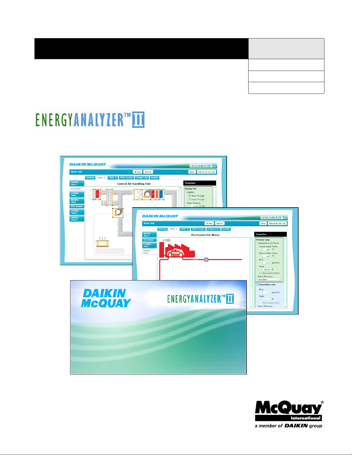
The McQuay EnergyAnalyzer™ II program provides a quick method for estimating energy
consumption in a typical building for a wide variety of HVAC systems. In addition, it can provide
operating cost and life cycle analysis between two or more HVAC systems so that the best financial
decision can be made. EnergyAnalyzer™ II should be used in a preliminary design phase in which
justification of a system or improved equipment efficiency is necessary.
EnergyAnalyzer™ II System Requirements
EnergyAnalyzer™ II is a web-based application; the user must meet certain requirements to access
and use the program:
Internet access- Internet access of any type is required to access EnergyAnalyzerII
Microsoft Silverlight-If Microsoft Silverlight is not installed or the current version is not
installed on the user’s computer, a webpage will appear that sends the user to the Microsoft
website to download the latest version at no charge Microsoft Silverlight is directly
compatible with Microsoft and Mac operating systems.
McQuayTools Suite user ID- To obtain a McQuayTools Suite user ID, refer to user
manual.
Basic Workflow
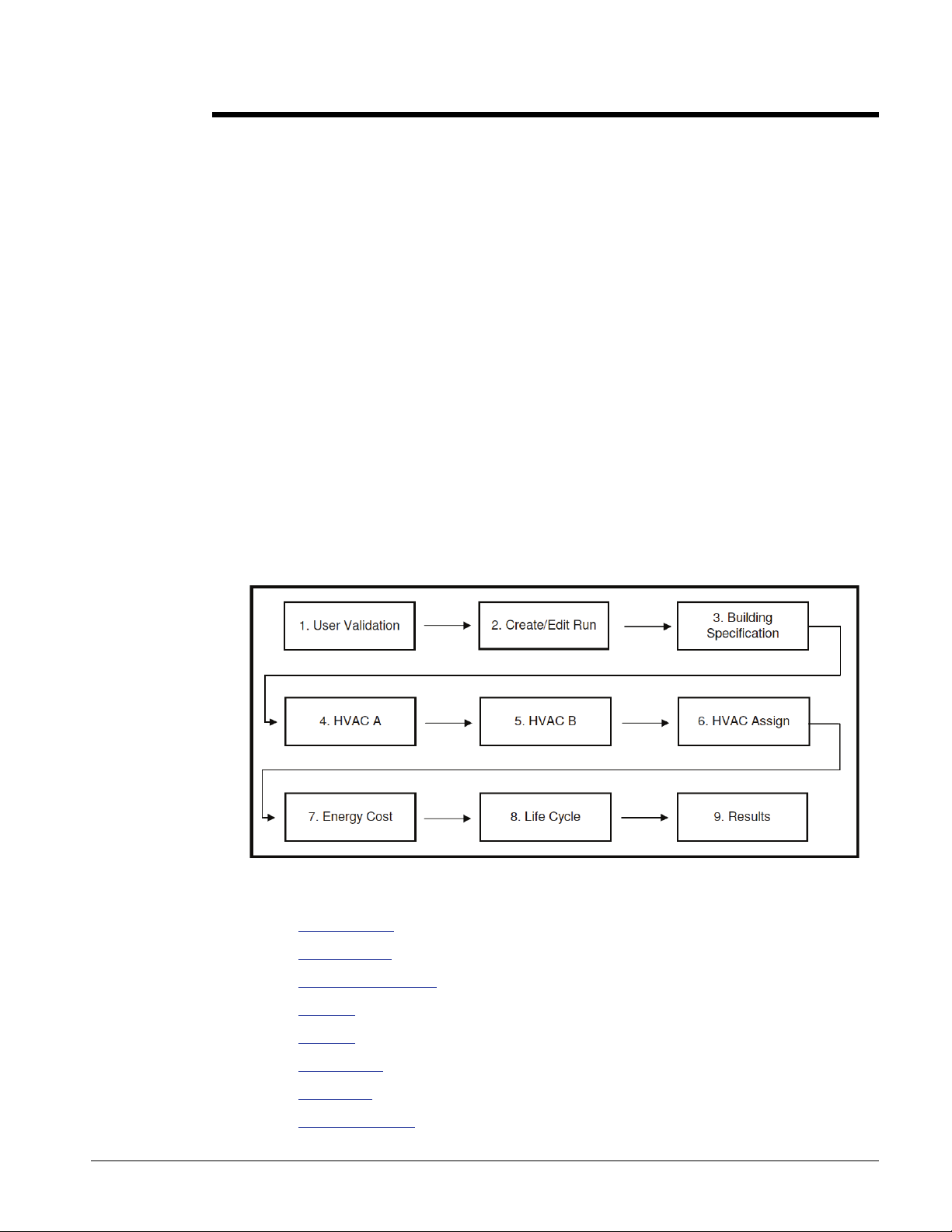
The flowchart shown in Fig. A indicates the steps required to navigate through
EnergyAnalyzer™ II.
EnergyAnalyzer™ II program can be divided into nine easy steps to compare two different
HVAC options. To get detailed information on each step please refer to user manual:
1. User validation
2. Create/edit run
3. Building specification
4. HVAC A
5. HVAC B
6. HVAC assign
7. Energy cost
8. Life cycle analysis
IM 269 3
Page 3
9. Results
EnergyAnalyzer™ II is designed to help you compare energy costs of two different HVAC systems.
Energy analysis runs can be completed with or without detailed information about a particular job.
Below are required steps for preliminary and detailed analyses.
Steps for Preliminary (Four Step) Analysis
For an energy analysis on job with very little information or a job in the earliest part of the
preliminary design phase, a simple analysis with default building specifications and energy cost
approximations is most appropriate. These types of analyses only require four steps:
1. User validation
2. Create/edit job
3. Define one or two HVAC Systems
4. Results
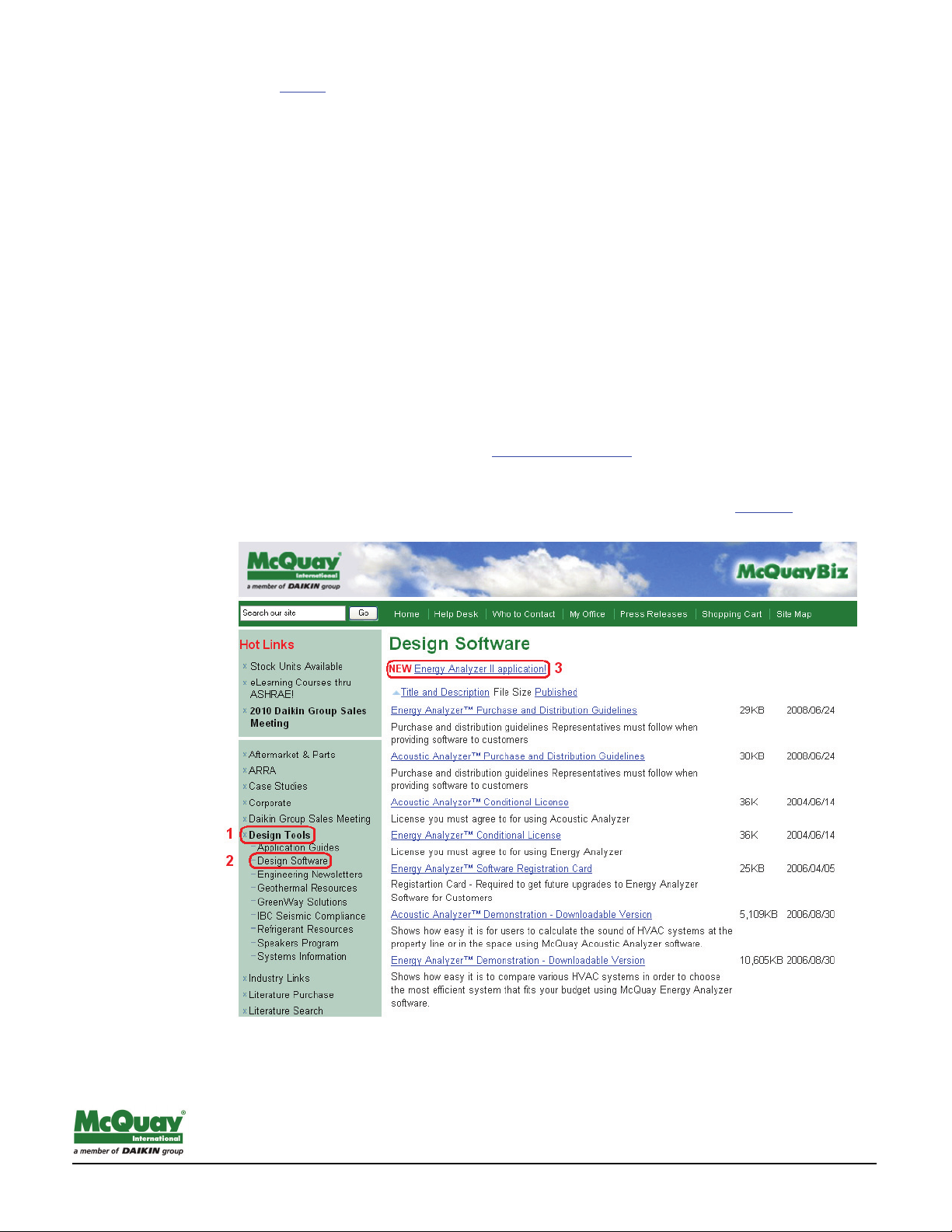
1. User Validation
the user may gain access by logging in at www.mcquaybiz.com/ and navigating to the Design Tools
page from the left navigation column. Additional links will be available from this page. Select the
Design Software link. At the top of the Design Software page will be a link to the EnergyAnalyzer™
II application, which will bring the McQuayBiz logged in user to their custom Jobs List
link to the energy analysis application can be found in the My Office section of McQuayBiz.
. Another
2. Create/Edit Job
©2003 McQuay International (800) 432-1342 www.mcquay.com AG 31-000 (00/03)
Page 4

Creating a new job is the first step in starting the energy analysis. A new job must be created any time
the user would like to compare two new HVAC systems.
To Create a New Job:
1. After user validation, select the New button
2. Provide basic information regarding the Job Name, building type, building construction
and HVAC equipment performance defaults, building area, and location. Any
information provided may be edited at a later time on following screens. Select the OK
button to proceed.
3. Defining the HVAC Systems
EnergyAnalyzer™ II has the capability of analyzing a building with two different HVAC system
designs. The base system is referred to as HVAC A, while the alternative HVAC system is called
HVAC B. Within each HVAC design, two different systems can be specified.
Enter information on the System Type, Central Cooling Plant (if applicable), and Central Heating Plant
(if applicable). Depending on the chosen System Types or the existence of System 2, all relevant
secondary tabs will appear.
4. Results / Analysis
To obtain the two systems, the user must run a simulation by selecting the Results primary tab
and Issue secondary tab. The user must select the Start Design Day or Start Full Year button
located below the progress bar. Design days runs do EnergyPlus simulations for heating and cooling
design days. Full simulation runs both HVAC A and B simulations annually at sub-hourly intervals
to obtain energy and energy cost data for comparison.
Three secondary tabs are available to the user:
Issues- Users can start and stop simulations from here. A summary of simulation run
errors, warnings, and notes will automatically be generated to alert the user of possible
simulation invalidators.
Summary- Quickly scroll through a summary of the building and energy cost and
consumption comparisons.
Reports- Users can customize the output document, supplied in HTML format, for
presentations and simulation validation. Outputs include summaries of input data,
energy comparison graphs, energy cost tables, and much more. See the Report section
for a more thorough review of available outputs. Select the particular outputs of interest
by selecting the checkboxes next to the tables or graphs of interest. To produce the
selected tables and graphs in HTML format, select the Generate Report button at the
bottom of the main screen.
Steps for Detailed Analysis
This section describes steps to perform an energy analysis on a job which is in the design
development phase when more detailed building specifications and energy cost information is
available. These types of analyses require nine steps:
1. User validation
2. Create/edit run
3. Building specification
4. HVAC A
5. HVAC B
6. HVAC assign
IM 269 5
Page 5

7. Energy cost
8. Life cycle analysis
9. Results
1. User Validation
the user may gain access by logging in at www.mcquaybiz.com/ and navigating to the Design Tools
page from the left navigation column. Additional links will be available from this page. Select the
Design Software link. At the top of the Design Software page will be a link to the EnergyAnalyzer™
II application, which will bring the McQuayBiz logged in user to their custom Jobs List
link to the energy analysis application can be found in the My Office section of McQuayBiz.
. Another
2. Create/Edit Job
Creating a new job is the first step in starting the energy analysis. A new job must be created any time
the user would like to compare two new HVAC systems.
To Create a New Job:
3. After user validation, select the New button
Provide basic information regarding the Job Name, building type, building construction and
HVAC equipment performance defaults, building area, and location. Any information provided
may be edited at a later time on following screens. Select the OK button to proceed
3. Building specification
©2003 McQuay International (800) 432-1342 www.mcquay.com AG 31-000 (00/03)
Page 6

The general building information will define the type, size, and location of a building. For new
jobs, the Edit Building Definition pop-up dialog will appear before taking the user to the main
building specification page. For previously created jobs, the general building information may be
edited from the Building primary tab and General secondary tab by selecting the Edit button.
Additionally, the exterior wall, roof, floor, and window types can be modified to meet the design
specifications from the Building primary tab and Construction secondary tab.
Further along in the design process, the areas and use-characteristics of spaces types will be more
well defined and can be edited in the application from the Building primary tab and Activities
secondary tab.
4 and 5. Defining the HVAC Systems
EnergyAnalyzer™ II has the capability of analyzing a building with two different HVAC system
designs. The base system is referred to as HVAC A, while the alternative HVAC system is called
HVAC B. Within each HVAC design, two different systems can be specified. Definition of the HVAC
systems is characterized in the primary HVAC A and HVAC B tabs in the System Specs secondary tab.
On the System Specs main screen are two sections, one describing System 1 and the other describing
System 2 of HVAC A (or B). If a second system exists for HVAC A, check the System 2 check box and
the descriptors will bold.
To describe a system, the user must enter information on the System Type, Central Cooling Plant
(if applicable), and Central Heating Plant (if applicable). The System Type pull-down menu includes
a list of systems that directly condition the spaces from either a local or central location.
Examples of System Types include a central air handling unit and VRV. The Central Cooling Plant
describes the system that supplies a cooling source to the chosen System Type. Central Cooling
Plants include chillers and DX condensing units. The Central Heating Plant describes the system
that supplies heating to components in the chosen System Type. Examples of Central Heating Plants
include boilers and district hot water.
Depending on the existence of chosen System Type and if System 2 exists, all relevant secondary
tabs will appear. The available secondary tabs including Secondary, Cooling Plant, and Heating
Plant will allow the user to add detailed information on the components of the system. The
interactive main screens in the HVAC secondary tab component specification screens allow users to
roll their mouse over the individual components and see the name of the specific component. If
the background of the component is shaded a light blue, it indicates that the properties of the component
can be specified by the user. By clicking on the component, the properties side bar will automatically
scroll to the properties of that component.
6. Assigning Zones to Systems
If both HVAC A and HVAC B have only one system defined each, no user input is required on the
HVAC Assign primary tab.
If either HVAC A or HVAC B has two systems defined for the building, they will need to be assigned
in HVAC Assign under the corresponding secondary tab (HVAC A/B). The assignment is relatively
straightforward. In the HVAC Assign table there will be 5 columns: Name, Area, Square Footage,
System 1, and System 2.
The System 1 and System 2 columns represent which system will serve each particular activity.. A
particular activity can only be served by a single system. To assign a system for an activity (row),
select the system (column) circle which represents the HVAC equipment serving it.
IM 269 7
Page 7

7. Defining Utility Costs
For many users, building energy usage is best expressed in energy cost. Energy cost differences
are generally what can justify one system versus another. Energy costs are the estimated annual cost
of running the analogous building including lights, plug loads, HVAC systems, and anything else
that requires electricity, gas, or water. Energy costs generally take into account source energy
efficiencies (versus site energy efficiencies analyzed in the simulation). EnergyAnalyzer™ II will
provide an estimated difference in building energy costs between HVAC A and HVAC B.
To characterize the utility rates, the user should select the Energy Cost primary tab. Under the
secondary tabs, the user may define costs for electricity (demand and usage), natural gas, and water
or choose to use the default rates based on the location. Only one rate structure may be specified and
it will apply to both HVAC A and HVAC B.
8. Life Cycle Analysis
The purpose of life cycle analysis is to move away from comparing two systems on a first cost basis
and compare them over the life span of the equipment. A life cycle analysis looks at the cost to buy
the equipment, plus the cost to run and maintain that equipment over its useful life. While one type
of equipment may be more expensive to buy at first glance, the utility and maintenance cost to run it
may be less expensive than other equipment over the long run. In addition to the cost of running the
equipment, this approach also factors in the cost or benefit of saving or investing money over the life
of a system.
To complete a life cycle analysis, the user must enable the capability. Navigate to the Life Cycle
Analysis primary tab and check the Enable Life Cycle Analysis checkbox. In order to make a
comparison some general assumptions must be defined as well as specific information pertaining to
the specific systems being compared.
Capital Costs are required for both HVAC A and B in the comparison. The costs can be the
difference between building costs, HVAC system costs or just equipment costs. For the actual
calculations, it is the difference between the values that is important. The program will not accept $0
so if the incremental cost is known, add $1 for the “low cost” Alternative.
9. Results / Analysis
Under the Results primary tab, the user has the ability to run the simulation comparison and view and
print the results. To run a simulation, select the Results primary tab and Issue secondary tab. The
user must select the Start Design Day or Start Full Year button located below the progress bar.
Design days runs do EnergyPlus simulations for heating and cooling design days. Full simulation
runs both HVAC A and B simulations annually at sub-hourly intervals to obtain energy and energy
cost data for comparison.
Three secondary tabs are available to the user:
Issues- Users can start and stop simulations from here. A summary of simulation run
errors, warnings, and notes will automatically be generated to alert the user of possible
simulation invalidators.
Summary- Quickly scroll through a summary of the building and energy cost and
consumption comparisons.
Reports- Users can customize the output document, supplied in HTML format, for
presentations and simulation validation. Outputs include summaries of input data,
energy comparison graphs, energy cost tables, and much more. See the Report section
for a more thorough review of available outputs. Select the particular outputs of interest
by selecting the checkboxes next to the tables or graphs of interest. To produce the
©2003 McQuay International (800) 432-1342 www.mcquay.com AG 31-000 (00/03)
Page 8

selected tables and graphs in HTML format, select the Generate Report button at the
bottom of the main screen.
IM 269 9
 Loading...